
Deploying ACI - Bitly
955
|||||||||||||||||||| ||||||||||||||||||||
-
Upload
khangminh22 -
Category
Documents
-
view
0 -
download
0
Transcript of Deploying ACI - Bitly

About This E-BookEPUB is an open, industry-standard format for e-books. However, support for EPUBand its many features varies across reading devices and applications. Use your deviceor app settings to customize the presentation to your liking. Settings that you cancustomize often include font, font size, single or double column, landscape or portraitmode, and figures that you can click or tap to enlarge. For additional information aboutthe settings and features on your reading device or app, visit the device manufacturer’sWeb site.
Many titles include programming code or configuration examples. To optimize thepresentation of these elements, view the e-book in single-column, landscape mode andadjust the font size to the smallest setting. In addition to presenting code andconfigurations in the reflowable text format, we have included images of the code thatmimic the presentation found in the print book; therefore, where the reflowable formatmay compromise the presentation of the code listing, you will see a “Click here to viewcode image” link. Click the link to view the print-fidelity code image. To return to theprevious page viewed, click the Back button on your device or app.
||||||||||||||||||||
||||||||||||||||||||

Deploying ACIThe complete guide to planning,configuring, and managing ApplicationCentric Infrastructure
Frank Dagenhardt, CCIE No. 42081,Jose Moreno, CCIE No. 16601,
With contributions fromBill Dufresne, CCIE No. 4375
Cisco Press800 East 96th StreetIndianapolis, Indiana 46240 USA
||||||||||||||||||||
||||||||||||||||||||

Printed in the United States of America
1 18
Library of Congress Control Number: 2017962494
ISBN-13: 978-1-58714-474-5
ISBN-10: 1-58714-474-3
Warning and DisclaimerThis book is designed to provide information about Application Centric Infrastructure.Every effort has been made to make this book as complete and as accurate as possible,but no warranty or fitness is implied.
The information is provided on an “as is” basis. The authors, Cisco Press, and CiscoSystems, Inc. shall have neither liability nor responsibility to any person or entity withrespect to any loss or damages arising from the information contained in this book orfrom the use of the discs or programs that may accompany it.
The opinions expressed in this book belong to the author and are not necessarily thoseof Cisco Systems, Inc.
Trademark Acknowledgments
||||||||||||||||||||
||||||||||||||||||||
Deploying ACIThe complete guide to planning, configuring, and managingApplication Centric InfrastructureFrank Dagenhardt, Jose Moreno, Bill Dufresne
Copyright © 2018 Cisco Systems, Inc,
Published by:Cisco Press800 East 96th StreetIndianapolis, IN 46240 USA
All rights reserved. No part of this book may be reproduced or transmitted in any form or by any means, electronic or mechanical, including photocopying, recording, or by any information storage and retrieval system, without written permission from the publisher, except for the inclusion of brief quotations in a review.

All terms mentioned in this book that are known to be trademarks or service marks havebeen appropriately capitalized. Cisco Press or Cisco Systems, Inc., cannot attest to theaccuracy of this information. Use of a term in this book should not be regarded asaffecting the validity of any trademark or service mark.
Special SalesFor information about buying this title in bulk quantities, or for special salesopportunities (which may include electronic versions; custom cover designs; andcontent particular to your business, training goals, marketing focus, or brandinginterests), please contact our corporate sales department at [email protected] (800) 382-3419.
For government sales inquiries, please contact [email protected].
For questions about sales outside the U.S., please contact [email protected].
Feedback InformationAt Cisco Press, our goal is to create in-depth technical books of the highest quality andvalue. Each book is crafted with care and precision, undergoing rigorous developmentthat involves the unique expertise of members from the professional technicalcommunity.
Readers’ feedback is a natural continuation of this process. If you have any commentsregarding how we could improve the quality of this book, or otherwise alter it to bettersuit your needs, you can contact us through email at [email protected]. Pleasemake sure to include the book title and ISBN in your message.
We greatly appreciate your assistance.
Editor-in-Chief: Mark Taub
Alliances Manager, Cisco Press: Arezou Gol
Product Line Manager: Brett Bartow
Executive Editor: Mary Beth Ray
Managing Editor: Sandra Schroeder
Development Editor: Christopher Cleveland
Project Editor: Mandie Frank
||||||||||||||||||||
||||||||||||||||||||

Copy Editor: Bart Reed
Technical Editors: Lauren Malhoit, Sadiq Hussain Memon
Editorial Assistant: Vanessa Evans
Designer: Chuti Prasertsith
Composition: codemantra
Indexer: Erika Millen
Proofreader: Larry Sulky
Americas HeadquartersCisco Systems, Inc.San Jose, CA
Asia Pacific HeadquartersCisco Systems (USA) Pte. Ltd.Singapore
Europe HeadquartersCisco Systems International BV Amsterdam,The Netherlands
Cisco has more than 200 offices worldwide. Addresses, phone numbers, and faxnumbers are listed on the Cisco Website at www.cisco.com/go/offices.
Cisco and the Cisco logo are trademarks or registered trademarks of Cisco and/or itsaffiliates in the U.S. and other countries. To view a list of Cisco trademarks, go to thisURL: www.cisco.com/go/trademarks. Third party trademarks mentioned are theproperty of their respective owners. The use of the word partner does not imply apartnership relationship between Cisco and any other company. (1110R)
||||||||||||||||||||
||||||||||||||||||||

About the AuthorFrank Dagenhardt, CCIE No. 42081, is a technical solutions architect for Ciscofocusing on next-generation data center architectures. Frank has over 22 years inInformation Technology and holds certifications from HP, Microsoft, Citrix, and Cisco.A Cisco veteran of over 11 years, he works with customers daily, designing,implementing, and supporting end-to-end architectures and solutions. In recent months,he has been focusing on policy, automation, and analytics. Frank has worked on andcontinues to be involved in publications about Cisco products. He presents regularly atCisco Live on data center topics. He lives in Michigan with his wife and four wonderfulchildren.
Jose Moreno, CCIE No. 16601 and CCDE No. 20100008, attended the PolytechnicUniversities of Madrid and Milan. After he graduated, he started his career as a networkarchitect in a big data center in Germany, at Amadeus Data Processing. In 2007 hemoved to Cisco, where he started working as data center systems engineer. Since thenhe has worked in many different Cisco data center technologies, including Cisco UnifiedCompute System and the Cisco Nexus switching series. Since 2014 Jose has focused onCisco Application Centric Infrastructure as a technical solutions architect. Jose haspresented multiple times at Cisco Live. He lives with his wife and children in Munich,Germany.
Bill Dufresne is a Distinguished Systems Engineer and member of the DataCenter/Cloud Team at Cisco. He regularly works with customers on complex technicaldesigns while leading global teams in various disciplines. He has been with Cisco since1996 and has more than 31 years of experience in the IT industry. Bill has held severalindustry certifications, including Cisco CCIE for more than 19 years, VMware VCP,CISSP, Microsoft, and even Banyan Vines. He is an expert in Routing & Switching, DataCenter Compute Infrastructure, Software Defined Networking, Virtual Networking,Analytics, and foremost, an expert in Systems, Application, and Cloud Adoption. Bill isa frequent speaker at a multitude of industry conferences including Cisco Live,VMWorld, VMware Partner Exchange, VMware User Groups, EMC World, and variousother events. He has worked with many customers of all sizes, across verticals such asGlobal Financial; Transportation; Retail; Healthcare; State, Local, and NationalGovernment; and Higher Education. Bill lives south of Nashville, TN with hiswonderful wife, enjoying their ‘empty nest’ years.
||||||||||||||||||||
||||||||||||||||||||

About the Technical ReviewersLauren Malhoit has been in the IT industry for over 15 years, starting off as a systemsengineer, moving to pre- and post-sales, and finally working at Cisco as a technicalmarketing engineer for the INSBU for over three years. She’s currently the chieftechnologist and co-host of the Cisco TechWiseTV series.
Sadiq Memon has been with Cisco for 10 years, with 26 years of diversifiedexperience in the IT industry overall. He has been the lead architect from CiscoAdvanced Services for many data center projects covering Cisco’s Auto &Manufacturing customers globally. Sadiq is one of the few solutions architects fromCisco Advanced Services who started working on ACI technology during its incubationperiod. He has presented at Cisco Live and participates actively on various blogs andGitHub. Sadiq graduated with a degree in computer systems engineering and possessesseveral industry certifications, including Cisco’s CCIE and CCNA, VMware VCP-DCV,Citrix CCA, and Microsoft MCSE.
||||||||||||||||||||
||||||||||||||||||||

DedicationFrom Frank:
I would like to dedicate this book to my loving wife Sansi and our four children: Frank,Everett, Cole, and Mia. Sansi, your companionship and encouragement have and alwayswill be the key to any success I enjoy. Thank you for your love and support. Frank,Everett, Cole, and Mia, I thank God for you every day. I can’t wait to see where yourpaths take you. I would also like to further dedicate this book to my parents, Jim andPatty. Your guidance and upbringing made me who I am today and taught me that “youcan do anything you put your mind to”.
From Jose:
This book is dedicated to Yolanda. Thank you for getting the best out of me.
From Bill:
I would like to thank my family, foremost. Without their support of my work in thischallenging space, none of this would have been possible. Especially my lovely andsupportive wife, Jill. She always understands the demands of my work, when it takesme time zones away via plane or even a WebEx or Telepresence call. I would also liketo thank, posthumously, my maternal grandparents for instilling in me humility and awillingness to help solve challenges that others face. There are too many folks withinCisco to thank individually, but know that if you and I have worked together, you haveinspired me in some way. I would also like to thank the myriad of customers over mycareer. Each interaction has taught me something that I can apply in my future endeavors,and I hope that I have provided value to you likewise - Ancora Imparo.
||||||||||||||||||||
||||||||||||||||||||

AcknowledgmentsFrank Dagenhardt: I’d like to say thank you to Mark Stanton, who took a chance on meand hired me into Cisco all those years ago.
Thank you to Jim Pisano and James Christopher, for letting me be a part of the best teamin Cisco. Without our experiences over the last few years, this book wouldn’t have beenpossible.
Thank you to the INSBU and all of the product managers and TMEs. Thank you foraccess to information and documentation, as well as all the consultations you haveprovided over the years—especially Vipul Shah and John Weston.
Mary Beth Ray, thank you for your constant and unwavering support in this endeavorand your infinite patience every time one of my dates slipped.
Chris Cleveland, it was a pleasure to work with you again. Your expertise,professionalism, attention to detail, and follow-up were amazing as always. Thank youfor everything.
To our technical editors, Lauren Malhoit and Sadiq Memon: Having been a technicaleditor in the past, I understand better than most the dedication and effort you put into thisbook. Thank you for your technical expertise and honest and accurate feedback. Wecouldn’t have done this without you.
Thank-you to the entire production team for this book.
I’d like to thank my co-authors, Jose Moreno and Bill Dufresne. Jose, you are a rockstar! I really enjoyed working with you on this project. Even though we were half theworld away, we accomplished a lot. You are one of the best engineers I have ever met,and genuinely a great guy. Thanks for everything! Bill, thank you for your contributionsto this book. I learn something from you every time we work together. People like youand Jose are the reason why I love my job.
Finally, I want to thank God for the gifts He has given me and the opportunity to do whatI love to support my family. I couldn’t ask for more.
Jose: I would like to thank Uwe Müller, who made it possible for me, despite adifficult situation, to join the fascinating world of software-defined networking at Cisco.My gratitude also goes to Luciano Pomelli, James Christopher, and Matt Smorto, whogave me the chance to join an ACI-focused team.
I would like to give special recognition to Juan Lage, who has always been a lighthouse
||||||||||||||||||||
||||||||||||||||||||

for me, providing his expert technical knowledge and nontechnical wisdom—besidessharing a liking for the best soccer team in the world.
A big thank-you goes out to the production team for this book. Mary Beth Ray andChristopher Cleveland have been incredibly professional and a pleasure to work with. Icouldn’t have asked for a finer team. Huge thanks as well to Bart Reed and MandieFrank, who went through the pain of correcting my Spanish-influenced English.
A significant part of the work bringing this book to life was done by the technicaleditors, Lauren Malhoit and Sadiq Memon. It has been great to see how thoroughly youwent through every single line.
Lastly, I would like to thank my co-authors, Bill Dufresne and especially FrankDagenhardt, for their dedication and perseverance in making this book possible, and foroffering me the chance to contribute to this project. It has truly been an honor workingwith you.
||||||||||||||||||||
||||||||||||||||||||

Contents at a GlanceIntroduction
Chapter 1 You’ve Purchased ACI. Now What?Chapter 2 Building a FabricChapter 3 Bringing Up a FabricChapter 4 Integration of Virtualization Technologies with ACIChapter 5 Introduction to Networking with ACIChapter 6 External Routing with ACIChapter 7 How Life Is Different with ACIChapter 8 Moving to Application-Centric NetworkingChapter 9 Multi-TenancyChapter 10 Integrating L4-7 ServicesChapter 11 Multi-Site DesignsChapter 12 Troubleshooting and MonitoringChapter 13 ACI Programmability
Index
||||||||||||||||||||
||||||||||||||||||||

ContentsIntroduction
Chapter 1 You’ve Purchased ACI. Now What?Industry Trends and TransitionsNext-Generation Data Center Concepts
New Application TypesAutomation, Orchestration, and CloudEnd-to-End Security
Spine-Leaf ArchitectureExisting Infrastructure and ACI (Places in the Network)
ACI OverviewACI Functional Components
Nexus 9500Nexus 9300Application Centric Infrastructure Controllers
Protocols Enabling the ACI FabricData Plane ProtocolsControl Plane Protocols
Interacting with ACIGUINX-OS CLIOpen REST API
Introduction to the Policy ModelApplication Network Profiles and Endpoint GroupsVRFs and Bridge Domains
Fabric TopologiesSingle-Site ModelMulti-Pod ModelMulti-Site Model
Summary
Chapter 2 Building a FabricBuilding a Better Network
||||||||||||||||||||
||||||||||||||||||||

Fabric ConsiderationsRoles of a LeafFixed vs. Modular SpineIntegration Planning and ConsiderationsSecurity ConsiderationsPhased ACI MigrationNetwork-Centric Mode: Single TenantNetwork-Centric Mode: Multiple TenantEvolution to Application-Centric ModeMicrosegmentationBare-Metal WorkloadsVirtualized WorkloadsContainers
Virtual Machine Manager (VMM) IntegrationAVSVMwareMicrosoftOpenStack
Layer 4-7 ServicesManaged ModeUnmanaged Mode
Additional Multisite ConfigurationsCisco ACI Stretched FabricCisco ACI Multi-PodCisco ACI Multi-SiteCisco ACI Dual-Fabric DesignPervasive GatewayVMM Considerations
Summary
Chapter 3 Bringing Up a FabricOut of the Box
Suggested ServicesManagement Network
||||||||||||||||||||
||||||||||||||||||||

Out-of-Band NetworkIn-Band NetworkWhat to Expect when You Configure a ControllerFabric Infrastructure IP Range RecommendationsFabric Infrastructure VLAN RecommendationsCluster Size and APIC Controller IDAbout High Availability for APIC Cluster
Logging In to the GUI for the First TimeBasic Mode vs. Advanced ModeSystem TabTenants TabFabric TabVM Networking TabL4-L7 Services TabAdmin TabOperations TabApps TabDiscovering the FabricFabric Extenders
Required ServicesBasic Mode Initial SetupManagement NetworkNTPRoute ReflectorsVLAN DomainsAdvanced Mode Initial SetupAccess PoliciesVLAN Pools and DomainsAttachable Access Entity ProfilesInterface PoliciesInterface Policy GroupsInterface ProfileSwitch Profile
||||||||||||||||||||
||||||||||||||||||||

Management NetworkFabric PoliciesNTPRoute Reflectors
Managing Software VersionsFirmware RepositoryController Firmware and Maintenance PolicyFirmware Groups and PolicyMaintenance Group and Maintenance PolicyUsing the Scheduler
Configuration ManagementConfiguration SnapshotsConfiguration Backup
Summary
Chapter 4 Integration of Virtualization Technologies with ACIWhy Integrate Cisco ACI with Virtualization Technologies?Networking for Virtual Machines and Containers
Benefits of Cisco ACI Integration with Virtual SwitchesComparing ACI Integration to Software Network OverlaysVirtual Machine Manager DomainsEPG Segmentation and Micro-SegmentationIntra-EPG Isolation and Intra-EPG ContractsCisco ACI Integration with Virtual Switches in Blade SystemsOpFlexDeployments over Multiple Data Centers
VMware vSphereCisco ACI Coexistence with the vSphere Standard SwitchCisco ACI Coexistence with the vSphere Distributed SwitchCisco ACI Integration with the vSphere Distributed SwitchvCenter User RequirementsMicro-Segmentation with the VDSBlade Servers and VDS IntegrationCisco ACI Integration with Cisco Application Virtual Switch
||||||||||||||||||||
||||||||||||||||||||

Cisco AVS InstallationBlade Servers and AVS IntegrationDistributed FirewallVirtual Network Designs with VDS and AVSCisco ACI Plug-in for vSphere vCenter Server: Configuring ACI from
vCenterCisco ACI Coexistence with VMware NSX
MicrosoftIntroduction to Microsoft Hyper-V and SCVMMPreparing for the IntegrationMicro-SegmentationBlade Servers and SCVMM Integration
OpenStackML2 and Group-Based PolicyInstalling Cisco ACI Integration with OpenStackCisco ACI ML2 Plug-in for OpenStack Basic OperationsCisco ACI ML2 Plug-in for OpenStack SecurityCisco ACI ML2 Plug-in for OpenStack and Network Address
TranslationCisco ACI GBP Plug-in for OpenStack
Docker: Project ContivDocker Networking
KubernetesKubernetes Networking ModelIsolation ModelsCreating a New EPG for Kubernetes PodsAssigning a Deployment or a Namespace to an EPG with AnnotationsVisibility in ACI for Kubernetes Objects
Public Cloud IntegrationSummary
Chapter 5 Introduction to Networking with ACIExploring Networking in ACI
Groups and Contracts
||||||||||||||||||||
||||||||||||||||||||

Contracts Are ACLs Without IP AddressesFilters and SubjectsConcept of Direction in ContractsUnderstanding the Bidirectional and Reverse Filter OptionsConfiguring a Single Contract Between EPGsUsing vzAnyContract ScopeContracts and Filters in the Common TenantVRFs and Bridge DomainsVRF Design ConsiderationsBridge Domain Design ConsiderationsVRFs and Bridge Domains in the Common TenantVRFs in the Common Tenant and Bridge Domains in User TenantsLayer 3 External Connection in the Common Tenant with VRFs and
Bridge Domains in User TenantsIngress Versus Egress Filtering Design RecommendationsConnecting External Networks to the FabricL2 ConnectionsBasic Mode GUIAdvanced Mode Access Policies
Network-Centric VLAN=BD=EPGApplying Policy to Physical and Virtual WorkloadsMoving Devices to the Fabric, VLAN by VLANUnenforced vs. Enforced VRFL3 Connections to the CoreLayer 3 Out and External Routed NetworksL3 Out Simplified Object ModelBorder LeafsMigrating the Default Gateway to the Fabric
Summary
Chapter 6 External Routing with ACILayer 3 Physical Connectivity Considerations
Routed Ports Versus Switched Virtual Interfaces
||||||||||||||||||||
||||||||||||||||||||

Outside Bridge DomainsBidirectional Forwarding DetectionAccess PortPort ChannelVirtual Port ChannelGateway Resiliency with L3 OutHot Standby Routing Protocol
Routing ProtocolsStatic RoutingEnhanced Interior Gateway Routing ProtocolOpen Shortest Path FirstOSPF SummarizationBorder Gateway ProtocolBGP Route ProfileOutbound BGP PolicyBGP Protocol Statistics
External Endpoint Groups and ContractsExternal Endpoint GroupsContracts Between L3 Out EPGs and Internal EPGs
Multitenant Routing ConsiderationShared Layer 3 Outside ConnectionTransit RoutingSupported Combinations for Transit RoutingLoop Prevention in Transit Routing ScenariosWAN IntegrationDesign Recommendations for Multitenant External Layer 3
ConnectivityQuality of ServiceUser-Defined ClassesReserved ClassesClassification and Marking
MulticastMulticast Best-Practice Recommendations
||||||||||||||||||||
||||||||||||||||||||

Scenario 1: Leaf Switches Not Based on Cisco Nexus EX PlatformScenario 2: Leaf Switches Based on Cisco Nexus EX PlatformScenario 3: Hybrid Fabric with Leaf Switches Both Based on and Not
Based on Cisco Nexus EX PlatformMulticast Configuration OverviewMinimum Multicast Configuration: PIM-ASMMinimum Multicast Configuration: PIM-SSM
Summary
Chapter 7 How Life Is Different with ACIManaging Fabrics versus Managing Devices
Centralized CLISystem DashboardTenant DashboardsHealth ScoresPhysical and Logical ObjectsNetwork PoliciesFabric-wide PoliciesComparing the ACI Controller to Traditional Network Management
SystemsTroubleshooting the Deployment of Global PoliciesConfiguring Multiple Ports at the Same Time
Maintaining the NetworkFault ManagementFaults Across the NetworkFault LifecycleImmediate Fault Reporting for Change ValidationConfiguration ManagementEvaluating Change ImpactConfiguration Zones: Running Changes GraduallyCentralized Change DescriptionAtomicity of Network ChangesConfiguration SnapshotsNetwork Audit Trails
||||||||||||||||||||
||||||||||||||||||||

Upgrading the SoftwareBreaking the Shackles of IP Design
Access Control Lists Without IP AddressesQoS Rules Without IP AddressesQoS Rules Without TCP or UDP Ports
Physical Network TopologyACI as a Clos Fabric and Design ImplicationsConnecting Endpoints to Leaf SwitchesScaling an ACI Fabric Means Adding More Leaf SwitchesFabric Topology and LinksIndividual Device ViewPort View
Changing the Network Consumption ModelSummary
Chapter 8 Moving to Application-Centric Networking“Network-Centric” Deployments
Removing Packet Filtering in Network-Centric DeploymentsIncreasing Per-Leaf VLAN ScalabilityLooking at the Configuration of a Network-Centric Design
“Application-Centric” Deployment: Security Use CaseWhitelist vs. Blacklist ModelsEnforced vs. Unenforced: ACI Without ContractsEndpoint Groups as a Zone-Based FirewallDynamic EPG Relationships: Micro-Segmentation EPGsMultiple EPGs in the Same SubnetContract Security ModelInter-EPG CommunicationContract ScopeContract Subject SettingsFilter SettingsContract Subject LabelsContract InheritanceStateful Firewalling with Cisco Application Virtual Switch
||||||||||||||||||||
||||||||||||||||||||

Intra-EPG CommunicationAny EPGContract Definition Best Practices to Efficiently Use Resources
“Application-Centric” Deployment: Operations Use CaseApplication-Centric MonitoringQuality of ServiceImpact AnalysisAsset Allocation
Migrating to an Application-Centric ModelDisable Bridge Domain Legacy ModeDisable VRF Unenforced ModeCreate New Application Profiles and EPGsMove Endpoints to the New EPGsFine-Tune Security Rules
How to Discover Application DependenciesFocus on New ApplicationsMigrate Existing ApplicationsLegacy Application Dependency MappingCisco Tetration Analytics
Summary
Chapter 9 Multi-TenancyThe Need for Network Multi-Tenancy
Data-Plane Multi-TenancyManagement Multi-Tenancy
Multi-Tenancy in Cisco ACISecurity DomainsRole-Based Access ControlPhysical DomainsLogical Bandwidth Protection Through Quality of ServiceWhat Is a Tenant? What Is an Application?Logical Separation for Lines of BusinessLogical Separation for Security or Compliance
Moving Resources to Tenants
||||||||||||||||||||
||||||||||||||||||||

Creating the Logical Tenant StructureImplementing Management Multi-TenancyMoving EPGs and ContractsExporting and Importing Contracts for Inter-Tenant CommunicationImplementing Data-Plane Multi-TenancyWhen to Use Dedicated or Shared VRFsMulti-Tenant Scalability
External ConnectivityShared External Network for Multiple Tenants
Inter-Tenant ConnectivityInter-VRF External ConnectivityInter-VRF Internal Connectivity (Route Leaking)
L4-7 Services IntegrationExporting L4-7 DevicesMulti-Context L4-7 Devices
Use Cases for Multi-Tenancy ConnectivityACI as Legacy NetworkGranting Network Visibility to Other DepartmentsNetwork Shared Across Organizations with Shared ServicesExternal Firewall Interconnecting Multiple Security ZonesService Provider
Summary
Chapter 10 Integrating L4-7 ServicesInserting Services
How We Do It TodayManaged vs. UnmanagedEcosystem PartnersManagement ModelFunctional Profiles
Security for All HostsBuilding an End-to-End Security SolutionIntegrating FirewallsService Node Failover
||||||||||||||||||||
||||||||||||||||||||

Deploying Clustering for Physical Appliances (Cisco ASA Cluster)Virtual versus PhysicalIntegrating Security MonitoringIntegrating Intrusion Prevention SystemsCopy ServiceIntegrating Server Load Balancing and ADCTwo-node Service Graph Designs
Summary
Chapter 11 Multi-Site DesignsBringing Up a Second Site
Stretched Fabric DesignSite-to-Site Connectivity OptionsStretched ACI Fabric Preserves VM MobilityLoss of a Single APICSplit FabricStandby APICMultiple-Fabric DesignCisco Data Center InterconnectTransit Leaf and L3 Out ConsiderationsDCI or Inter-Pod Network ConsiderationsMultiple Fabric Connectivity Options
Multi-Pod ArchitectureACI Multi-Pod Use Cases and Supported TopologiesACI Multi-Pod Scalability ConsiderationsInter-Pod Connectivity Deployment ConsiderationsIPN Control PlaneIPN Multicast SupportSpines and IPN Connectivity ConsiderationsPod Auto-ProvisioningAPIC Cluster Deployment ConsiderationsReducing the Impact of Configuration Errors with Configuration ZonesMigration Strategies
Multi-Site Architecture
||||||||||||||||||||
||||||||||||||||||||

APIC Versus Multi-Site Controller FunctionalitiesMulti-Site Schema and TemplatesMulti-Site Use CasesStretched Bridge Domain with Layer 2 Broadcast Extension (Option 3)Stretched Bridge Domain with No Layer 2 Broadcast Extension
(Option 2)Stretched EPG Across Sites (Option 1.1)Stretched VRF with Inter-Site Contracts (Option 1.2)Shared Services with Stretched Provider EPGMulti-Site and L3 Out ConsiderationsLayer 3 Multicast Deployment OptionsMigration of Cisco ACI Fabric to Cisco ACI Multi-Site
Summary
Chapter 12 Troubleshooting and MonitoringYou Have a Poor Health Score. Now What?NX-OS CLI
Connecting to the Leaf SwitchesLinux CommandsMapping Local Objects to Global ObjectsVLAN IDsLegacy ModePort ChannelsSome Useful Leaf Commandsping
Troubleshooting Physical IssuesTroubleshooting CablingTroubleshooting Switch OutagesReplacing a Fabric SwitchTroubleshooting Contracts
Troubleshooting Tools in ACIHardware DiagnosticsDropped Packets: Counter SynchronizationAtomic Counters
||||||||||||||||||||
||||||||||||||||||||

Traffic Mirroring: SPAN and Copy ServicesSPAN Destination GroupsERSPAN TypesSPAN Source GroupsCisco ACI Scalability for SPAN SessionsNexus Data BrokerTroubleshooting WizardDefining the Troubleshooting SessionFaults in the Troubleshooting WizardStatistics in the Troubleshooting WizardContract Information in the Troubleshooting WizardEvents and Audits in the Troubleshooting WizardTraceroute in the Troubleshooting WizardAtomic Counters in the Troubleshooting WizardConfiguring SPAN from the Troubleshooting WizardEndpoint TrackerEffectively Using Your Fabric ResourcesUsing Traffic Map to Find Bandwidth BottlenecksUsing Capacity Dashboard to Detect Resource BottlenecksUsing ACI Optimizer to Plan for Changes
Monitoring Policies and StatisticsSNMP PoliciesSyslog PoliciesStatistics
Third-Party Monitoring Tools with ACI SupportIBM Tivoli NetcoolSevOneScienceLogicSplunkZenoss
Summary
Chapter 13 ACI ProgrammabilityWhy Network Programmability? Save Money, Make Money!
||||||||||||||||||||
||||||||||||||||||||

What Is Wrong with Previous Network Automation Concepts?SNMPNetwork Configuration Protocol and YANGProgramming Interfaces and SDKsWhat Is REST?What Is a Software Development Kit?
Cisco ACI Programming InterfacesCisco ACI REST APIREST API AuthenticationAPI InspectorREST API ClientsUsing REST APIs in Programming LanguagesCisco ACI Object ModelDebug Information in the GUIVisoremoqueryCisco ACI Software Development KitsPython SDK: CobraSimplified Python SDK: ACI ToolkitRuby SDKPowerShell SDKWhere to Find Automation and Programmability ExamplesDeveloping and Testing Your Code Without an ACI Fabric at HandCisco DevNetdCloudCisco ACI Simulator
Increasing Operational Efficiency Through Network AutomationOffering Visibility to the NetworkExternalizing Network ConfigurationExternalizing Switch Port ConfigurationExternalizing Security ConfigurationHorizontal Automation IntegrationsHorizontal Integration Examples Embedded in the Product
||||||||||||||||||||
||||||||||||||||||||

Horizontal Integration Example Through External AutomationAutomating the Generation of Network Documentation
Enabling Additional Business Models Through Network AutomationAgile Application Deployment and DevOpsContinuous Deployment and Continuous IntegrationLinux Containers and Microservices ArchitecturesConfiguration Management ToolsPrivate Cloud and IaaSIntegration with Cisco Enterprise Cloud SuiteIntegration with VMware vRealize SuiteIntegration with Microsoft Azure Pack and Azure StackIntegration with OpenStackHybrid CloudPlatform as a ServiceACI Integration with ApprendaMantl and Shipped
Cisco ACI App CenterSummary
Index
||||||||||||||||||||
||||||||||||||||||||

Reader ServicesRegister your copy at www.ciscopress.com/title/ISBN for convenient access todownloads, updates, and corrections as they become available. To start the registrationprocess, go to www.ciscopress.com/register and log in or create an account*. Enter theproduct ISBN 9781587144745 and click Submit. When the process is complete, youwill find any available bonus content under Registered Products.
*Be sure to check the box that you would like to hear from us to receive exclusivediscounts on future editions of this product.
||||||||||||||||||||
||||||||||||||||||||

IntroductionIt’s a whole new world in the data center compared to just a few years ago. Someengineers would question whether we even call it a data center anymore, and whetherwe should call it a cloud (private) edge instead. New data centers are being built orretrofitted with enhanced capabilities around performance, redundancy, security,visibility, L4-7 service insertion, automation, and operational efficiency. With thesegoals in mind, Cisco has launched ACI as its premier data center SDN (software-defined networking) platform in order to meet these changes and provide a platformwith the scalability, reliability, and comprehensive feature set required in the next-generation data center.
The purpose of this book is to provide a guide for IT professionals who might not befamiliar with Application Centric Infrastructure (ACI). It is intended to be used as a“go-to” resource for design considerations and for concise information on the mostcommonly used aspects of ACI.
Technet24||||||||||||||||||||
||||||||||||||||||||

Goals and MethodsThe goal of this book is to provide a field guide for designing and deploying ACI. Thisbook also tries to bridge the gap between traditional network architectures and ACI byexplaining why we do things the way we do. We’ve tried to bring this informationtogether into one place, with in-depth explanations. Having been network administratorsourselves, we the authors are conscious of the pressures and challenges of findingaccurate and relevant information, especially on new technology. We intend this book tobe a resource network administrators reach for first. Although there might be more thanone way to accomplish a networking requirement, this book focuses on the best way thatminimizes operational complexity and maximizes supportability. We realize and respectthat there might be corner-case scenarios that call for configurations not described inthis book, but we sincerely hope we address the vast majority of commonconfigurations.
||||||||||||||||||||
||||||||||||||||||||

Who Should Read This Book?The target audience for this book is networking engineers in organizations that want toincorporate Cisco data center technologies into their businesses—more specifically,professionals who want to learn about Cisco SDN for next-generation data centerfabrics and how Cisco is addressing this trend in the market.
Also, virtualization professionals willing to deepen their networking knowledge willhopefully find this book valuable and easy to follow—especially Chapter 4, whichdeals with the integration of Cisco ACI with virtualization technologies.
Finally, this book can be very valuable for technicians and operators who desire a solidconceptual background before working with Cisco Nexus 9000 products and solutions.
Technet24||||||||||||||||||||
||||||||||||||||||||

How This Book Is OrganizedThis book has been organized in a similar manner to how you might encounter differentdecision points when deploying a data center network fabric. The initial chapters startwith an introduction to ACI and focus on building or designing a fabric. The next stepafter deciding on a design is bringing up a fabric for the first time and integrating withvirtualization platforms. An introduction to networking in ACI and external connectivityare then explored. Next, we examine how to manage an ACI network versus atraditional network. With the drive toward microsegmentation, the need for increasedvisibility and control arises, which is why we next explore the migration to application-centric networking. Multitenancy is detailed before moving to the next topic, integratingL4-7 services, where any service device can be inserted into an application data flowquickly and easily. Most organizations are concerned with redundancy and highavailability, so we examine Multi-Site ACI designs next. This book would beincomplete if we helped you design and implement ACI without exploring how totroubleshoot and monitor an ACI fabric. The last chapter features an overview ofprogrammability and automation. Many organizations are trying to build their ownprivate cloud. We will examine the features and capabilities that ACI has to help youbecome cloud like or operationally efficient.
In particular, Chapters 1 through 13 cover the following topics:
Chapter 1, “You’ve Purchased ACI. Now What?”: This chapter provides thereader with a foundation for understanding what trends are driving the adoption ofACI in today’s data centers. In addition, a high-level overview of ACI and itscapabilities is provided.
Chapter 2, “Building a Fabric”: This chapter focuses on common decision pointswhen designing and building an ACI fabric.
Chapter 3, “Bringing Up a Fabric”: This chapter delves into the basicrequirements and how to interface with the devices to bring up a fabric for the firsttime.
Chapter 4, “Integration of Virtualization Technologies with ACI”: This chapterprovides the information needed to decide how to integrate with ACI and whichvirtualization technologies to use.
Chapter 5, “Introduction to Networking with ACI”: This chapter focuses on hownetworking is performed inside the ACI fabric as well as how it differs from howwe have done it in the past.
Chapter 6, “External Routing with ACI”: This chapter delves into how to connect
||||||||||||||||||||
||||||||||||||||||||

external networks and devices to ACI from a Layer 2 and Layer 3 standpoint. Chapter 7, “How Life Is Different with ACI”: This chapter provides insight intothe differences between managing a traditional network “switch by switch” andmanaging an ACI network as a single fabric with tenants and application policy.
Chapter 8, “Moving to Application-Centric Networking”: This chapter exploresthe advantages of configuring more granular policy based on applications and theirfunctions.
Chapter 9, “Multi-Tenancy”: This chapter covers the ability to create separatetenants on an ACI network. It explores some of the use cases for this feature and theeffect it may have on your network, security, and services resources.
Chapter 10, “Integrating L4-7 Services”: This chapter delves into the details ofintegrating services into the ACI fabric. It explores different device types, designscenarios, and how to implement them in ACI.
Chapter 11, “Multi-Site Designs”: This chapter provides an introduction to andoverview of the different ways ACI can be configured to meet redundancy orbusiness continuity requirements through the use of separate ACI fabrics.
Chapter 12, “Troubleshooting and Monitoring”: This chapter covers thetroubleshooting and monitoring tools built into ACI to help find and resolve issueswith the ACI fabric or the devices connected to it.
Chapter 13, “ACI Programmability”: This chapter provides an introduction to andoverview of automation programmability and how you can use it to become moreoperationally efficient with ACI.
Technet24||||||||||||||||||||
||||||||||||||||||||

You’ve Purchased ACI. Now What?
Well, you’ve decided to walk the Application Centric Infrastructure (ACI) path. Youmay be asking yourself, “Now what?” or “Where do I start?” Although every newproject raises questions like this, ACI takes things to a different level, because, for thefirst time in the history of networking, you have a truly novel way of building andoperating the infrastructure. Let’s talk about some of those basic changes you will learnabout in this book.
Industry Trends and TransitionsWe’ll start with why you even considered ACI in the first place. Industry changes areimpacting almost every aspect of IT. Applications are changing immensely, and we’reseeing their lifecycles being broken into smaller and smaller windows as theapplications themselves are becoming less structured. What the network used to controland secure has changed greatly with virtualization via hypervisors. With containers andmicroservices being deployed more readily, we’re seeing change happen at a muchfaster pace.
Recall what moving application workloads from “physical” to “virtual” meant to trafficflows within the data center. Those long-established north-south flows weresignificantly disrupted to a more east-west direction. Assume, for a moment, that thecollapse ratio of a physical-to-virtual move is 1:30. Now imagine the potential collapseratio using containers at a factor of 1:300. Consider the impact of this new east-westpattern. As we look at these new traffic flow patterns, consider that many data centersstill contain mainframes and other legacy compute elements, as well as physical x86-based bare metal servers, hypervisors, containers, microservices, and whatever may benext. This is where ACI excels: It supports various workload platforms simultaneouslyand consistently.
This faster pace necessitates change in how the networks are built, maintained, andoperated. It also requires a fundamental change to how networks provide security via
Technet24||||||||||||||||||||
||||||||||||||||||||

segmentation. Firewalls alone cannot keep pace, and neither can manual device-by-device configuration. No matter how good you are at copying and pasting, you’reeventually going to commit a mistake—a mistake that will impact the stability of thenetwork. It is time for an evolutionary approach to systems and network availability. Itis time to embrace policy.
Next-Generation Data Center ConceptsThe days of the static data center ended when x86 virtualization took hold in the 2000s.However, that was not the end of the story for workload agility. Just as our personalcommunication devices get more powerful and easier to use, so too have applicationarchitectures. Yes, containers and microservices are becoming a reality because theagility, comparative availability, and scale of virtualized workloads are not enough forbusinesses going forward. With that in mind, what customers had called data centers arenow being retooled as private clouds. In all, this is a useful change because it enablesthe infrastructure to provide what the applications need instead of the applications beingmade to fit a system’s model.
Along with new models for applications, the impact on the network has been a changeto much more of an east-west traffic flow. The use of hypervisors to host applicationworkloads began this new traffic paradigm. If you consider the density of workloads perhost on a hypervisor, containers as a method of virtualization offer a much higherdensity, due to the fact that only the application and not the operating system is includedin each container. This is the impact we now must build networks to support, spreadingthe traffic patterns between various applications’ workload elements. We must alsoconsider the fact that there will continue to be host-, hypervisor-, container-, andmicroservice-based workloads all coexisting on the same network infrastructure.
This means that the network now needs to be as flexible and scalable (for both increaseand decrease) as the applications it supports. This is where a workload-independentnetwork policy really enables IT to provide that private cloud capability for workloads,whether bare metal, virtualized, containers, or microservice based. Without thisconsistent policy, the effect of having to manage different types of workloads,potentially for the same application, becomes a huge administrative burden. If weconsider that between 60% and 70% of the cost of an infrastructure is administrative(that is, the people operating it), it’s the first area of focus for bringing those costsdown. In addition, use of network policy enables the eventual movement of workloadsbetween private clouds (including multiple locations) and public clouds, thus enablingthe realization that is the hybrid cloud.
||||||||||||||||||||
||||||||||||||||||||

New Application TypesWe’ve briefly touched on new application models. We can follow the change inapplication design with the change in how we more effectively communicate via smartdevices of all types. Whereas applications used to reside exclusively inside the walls ofthe data center, now the applications (or elements of them) can also reside in the publiccloud or on the smart device itself. Let’s follow the well-understood model of the smartdevice application. It must be compact in size and able to be versioned with someregularity. You are certainly well aware of how you see daily updates to certain smartdevice applications. This is the new model of application development and maintenancethat traditional data centers must be able to adapt to in order to become private cloudinfrastructures.
So how do we take something like a smart-device application and apply it to somethinglike an Enterprise Resource Planning (ERP) style application? Consider all the movingpieces of an ERP application: There are presentation tier elements, several databaseelements, and application logic of multiple elements such as customer contacts,projects, products, and so on. Let’s take just the most common of these elements: thepresentation tier (in essence, the web front end). This can now evolve into a smart-device element, but some level of access from traditional x86-based laptops anddesktops also needs to be present. In recent applications (many are called traditionalapplications), these web servers provided content to browsers via multiple ports andprotocols, for example including TCP-80, TCP-443, TCP-8080, TCP-8443, and UDP-FTP. Scale was achieved by adding more web servers, all configured identically.
You might think that having 10 or more web servers configured identically would bejust fine. However, consider the recent security vulnerabilities on SSL (eventually onmultiple TCP ports like 443, 8443, and so on). Now having to patch every server forthat vulnerability basically takes the application out of service or leaves criticalvulnerabilities in the application. Instead, modern application design breaks thoseelements down to the very essence of the service they provide—the microservice.Imagine being able to patch the SSL vulnerability by creating new operating elements ofthe presentation tier that include the SSL fix for ports 443 and 8443 and deploy themwithout touching the port 80 and 8080 microservices? Think of this when it comes toscale of the application.
Consider the idea of what in the retail industry is known as “looks to books.” In otherwords, someone browsing for information or a product is a “look”, whereas a userwanting to perform a secured transaction is a “book.” Each of these uses different portsof the application tier. Should you scale the SSL portion of the application tier if you seea spike in look-related traffic? It’s not the most efficient use of infrastructure resources.
Technet24||||||||||||||||||||
||||||||||||||||||||

Therefore, microservices design provides the freedom to scale, patch, update, andquiesce elements of any application more effectively than monolithic, traditionalapplications. However, the infrastructure also needs to be aware of this scale, both upand down, to better support the applications. You’ll see how this is achieved as youread through this book.
Automation, Orchestration, and CloudWe have only briefly mentioned cloud concepts to this point. However, with the changescoming in application models, cloud (in the form of public, private, and hybrid models)is a reality for customers of any size and sophistication. As such, the building blocks ofsuccessful cloud deployments and operations begin with a flexible infrastructure thatprovides some level of policy-based configuration. For private cloud and eventuallyhybrid cloud to be realized, all infrastructure elements must become pools of resources.Think of how effective Cisco Unified Compute System (UCS) Manager has been attaking a bunch of x86 compute resources and, via policy, creating easy-to-scale, -manage, and -maintain pools of compute for application consumption. The same mustnow be applied to the network. The Cisco ACI policy provides similar ease of scale,management, and maintenance to that found in UCS Manager. However, those are justthe building blocks of cloud.
Automation and orchestration are where we find the tools to provide the flexibility andpotential to provide self-service to the business and the applications that operate it.First, let’s better define the terms orchestration and automation because they tend to getused interchangeably. Note that automation, by definition, is the ability to make aprocess work without (or with very little) human interaction. Can you automate thedeployment of a configuration of compute elements, including operating system andpatches, via a tool like Puppet or Chef? Absolutely. One could argue that Cisco UCSManager is automation for compute hardware configuration, and that the ACI policymodel is automation for network and L4-7 services within it. I would agree with both ofthese assertions. However, orchestration means taking those infrastructure elementsbeing automated and tying them together into a more meaningful motion to achieve anend result.
Thus, orchestration tools must address more than one domain of the infrastructure andcan also include items within or supplied by the infrastructure. Good examples oforchestration include tools such as Cisco UCS Director, Cisco CloudCenter, CiscoProcess Orchestrator, VMware vRealize Orchestrator, Heat for OpenStack, and others.These examples all allow, in varying degrees, the ability to string together tasks andprocesses that can provide a self-service capability for application deployment,
||||||||||||||||||||
||||||||||||||||||||

application retirement, user on- and off-boarding, and so on. The key is that automationon its own provides the ability to lower that 60–70% administrative cost to the datacenter infrastructure, and orchestration provides the tools to realize a flexible and real-time infrastructure for private, public, and hybrid cloud environments. You cannotachieve true cloud operations without automation and orchestration.
End-to-End SecurityDo the bad guys ever sleep? That question is best answered when we first understandwho the bad guys are. Because we cannot identify all immediate risks to aninfrastructure or a company—and, yes, even headlines can be severely impacting tobusiness—we must do our utmost to keep the infrastructure from harm and fromharboring harm, both from the outside and within. Even with an unlimited budget,security cannot be considered 100% or ironclad. However, if the infrastructure isflexible enough—perhaps the network even provides scalable and flexible security—your environment can be less hospitable or accommodating to the so-called “bad guys.”
To this end, let’s focus on the network. Until the advent of ACI, the network mantra hadbeen “Free and Open Access” from its inception. I recall hearing this from several ofmy university customers, but even they have been forced to change their viewpoint. Inlegacy networks, we had free and open access, which necessitated the use of firewalls,where we only opened ports and protocols appropriate to allow applications to operatecorrectly and provide protocol inspections. This is something the firewall wasoriginally designed to do. However, something the firewall was never originally designto do was to act as a route point within the network. Due to the need to secure segmentportions of the network and provide bastion or edge security, we have forced firewallsto become routers, and they pose severe limitations on the routing capabilities andoptions for a legacy network.
Now consider the ACI network, where, as you might have heard already, a whitelistsecurity policy is in place. Nothing can communicate unless the network policyexplicitly allows it. Are you thinking firewall now? Well, not so fast. Although theCisco ACI whitelist model does change the paradigm, it is more akin to stateful accesscontrol lists (ACLs) at the TCP/UDP level within a switch or router—effective, butcumbersome in the legacy or blacklist model sense. However, there is still a need tohave deep protocol inspection and monitoring, which is something firewalls andintrusion prevention systems (IPSs) do very well. So let’s get those devices back todoing what they do best and let ACI handle the forwarding and ACL-based security. Asyou will see in the book, IPSs and such network services devices can be automaticallyinserted in the network with ACI services graph (see Chapter 10 “Integrating L4-7
Technet24||||||||||||||||||||
||||||||||||||||||||

Services”).
Have you ever experienced a completely correct configuration on a firewall? No cruftfrom legacy configurations or applications long since retired? Probably not, and this isdirectly due to the fact that most applications and their needed communication protocolsand ports are not truly understood. What’s the usual outcome of this misunderstanding?A very open firewall policy. Ultimately the thought of security behind a firewallconfigured in such a manner is as hollow and gaping as the open pipe the firewallpermits to not impact application communication, thus favoring ease of use oversecurity.
Finally, how do we approach securing different applications from each other or fromimproper access? Effective segmentation is the answer, and ACI provides the industry-leading option for that. From multi-tenancy and endpoint group (EPG) isolation toindividual workload segmentation for remediation or rebuild when an intrusion isfound, Cisco ACI can act on these items for any type of workload—bare metal orvirtualized. Additionally, Cisco ACI can offer enhanced segmentation that starts outsideof the data center via TrustSec. This capability, based on a device or user credentials,only allows packet flows to specific segments within the ACI fabric, which effectivelyallows segmentation of users of, say, a payroll system or sales data from the endpoint tothe application elements hosted on an ACI fabric, inclusive of firewall, IPS, and otherrelevant L4-7 services.
Spine-Leaf ArchitectureSo how does all this occur? Couldn’t we just create new forwarding paradigms forexisting network architectures and carry on? In a word, no. One of the great impacts inIT in the last ten or so years has been virtualization. This has caused a huge shift intraffic flows within the data center, and if we project forward to cloud-nativeapplications built using microservices, this impact will increase. Thus, a change indesign was necessary and, quite honestly, it’s about time for a change. Gone are the daysof data center networks being defined by a “core, distribution, access” model. A newrobust model that scales east-west without impact while maintaining reachability canbring new capacities and the required flow-awareness. Spine-leaf is the name of thisnew model. It simply allows for true accessibility in a deterministic path across theentire data center fabric. This is the basis of Cisco ACI, with a few extras added in.
When we say Cisco ACI has extras, essentially we mean that spine-leaf is the newunderlying architecture of any modern data center network design. No matter which datacenter vendor you talk to (Cisco, Arista, Juniper, or VMware), we are all building our
||||||||||||||||||||
||||||||||||||||||||

next-generation data centers leveraging this spine-leaf architecture. The control-planeprotocols may differ from design to design, but in essence a highly scalable design usingthe two-stage spine-leaf model is the key base to build from. Cisco ACI’s extras includewhitelist segmentation, Virtual Extensible LAN (VXLAN) overlay, centralized policyconfiguration, and more.
Why a VXLAN-based overlay? Overlays are not new in networking; they have existedat least since the days when Multi protocol Label Switching (MPLS) was invented.Let's consider that analogy for a moment. Originally, MPLS was created in order tomake service provider networks cheaper (although its current applicability hastranscended by far that initial objective). The edge network devices that customersconnect to (called in MPLS jargon Provider Edge or PE) would communicate to eachother via tunnels. The core network routers (called Provider or P devices) would justprovide connectivity between the PE devices, and would be oblivious to whatever thePE devices were transporting inside of their tunnels. Thus, they did not need to learnevery single customer route, but just a bunch of internal prefixes. That allowed the useof devices with fewer hardware resources as P routers.
The VXLAN-based overlay in Cisco ACI follows the same primary objective: Leafswitches (think PE devices) establish VXLAN-based tunnels with each other thattraverse the spine layer. Spine switches (comparable to P routers) are there to providemassively scalable IP connectivity, but not much more (with one notable exception, aswe will see at the end of this section). Consequently, all intelligence needs to bedelivered at the tunnel endpoints, the leaf switches. Note that this is a dramaticconceptual difference when comparing VXLAN fabrics with traditional networks:While in traditional networks most of the intelligence resides in (typically) two central,highly critical devices, in VXLAN overlays the intelligence is distributed across theleaf switch layer, making the fabric much more scalable and resilient.
You might ask whether there is an increased price associated with spine-leaf designs:After all, we used to have two intelligent devices in legacy networks at the distributionlayer, but now we have possibly tens, if not hundreds, of intelligent (and potentiallyexpensive) devices at the leaf layer. Wouldn't that increase the overall cost of a spine-leaf architecture? The answer to this question is two-fold: On one hand, you canprogram leaf switch intelligence in relatively cheap application specific integratedcircuits (ASICs), a discipline in which the Cisco Nexus 9000 – the hardware basis ofCisco ACI – excels. On the other hand, since the intelligence is now distributed acrossthe network edge and not centrally located, leaf switches do not need to know everysingle detail of the complete network.
Reflect for a second on the previous sentence. It might sound obvious, but it brings
Technet24||||||||||||||||||||
||||||||||||||||||||

another paradigm shift for networking professionals: The scalability of a network is notdetermined by the scalability of the individual switches, but depends on the networkdesign. For example, if you have a look at the Verified Scalability Guide for CiscoAPIC at cisco.com, you will see that in the main section of the document there are twocolumns: Per Leaf Scale and Per Fabric Scale. Take, for example, the number of bridgedomains, a concept roughly equivalent to that of a VLAN, as we will see later in thischapter. Each Cisco ACI leaf switch supports up to 3500 bridge domains in legacymode (see more about legacy mode in Chapter 8, “Moving to Application-CentricNetworking”), but a single Cisco ACI fabric can support up to 15,000 bridge domains.
In legacy networks you would probably configure every VLAN everywhere, since youcould not possibly know in advance where the workloads for that particular VLANmight attach to the network. Now you need to be conscious with resources since youcannot fit 15,000 bridge domains in every leaf switch. Fortunately. Cisco ACI takescare of the efficient configuration of network resources automatically, and it will onlydeploy configuration wherever it is needed. For example, if a certain ACI leaf switchdoes not have any workload attached that is connected to a specific bridge domain, itdoes not make any sense consuming resources for that bridge domain. Therefore the BDwill not be programmed in the hardware of that leaf switch.
There is an additional implication of this new scalability design model: You should notput too many workloads on individual leaf switches, since their scalability is limited.For example, if you are thinking about building up a Cisco ACI fabric by connecting abunch of Fabric Extenders (FEXs) to your leaf switches, and attaching hypervisor hoststo the Fabric Extender ports, think again. How many virtual machines will you beconnecting to a single leaf switch? Are you still within the scalability limits of a singleleaf switch? Or would it be more economical using multiple leaf switches instead ofFabric Extenders? Obviously, the answers to these questions depend on manyparameters, such as the server virtualization ratio, or the average number of virtualmachines per VLAN. Chapter 2, “Building a Fabric,” will dive deeper into these topics.
The leaf switch is where all the exciting networking happens. Traditional L2 and L3forwarding operations happen on the leaf. Edge routing with dynamic protocols forreachability, such as Border Gateway Protocol (BGP), Open Shortest Path First(OSPF), and Enhanced Interior Gateway Routing Protocol (EIGRP), on leaf ports willturn a leaf with external access into a border leaf. This is not a special designation orswitch hardware model, just the nomenclature to designate that a particular leaf switchplays a border role in the fabric. You will also note that the entire fabric is a routednetwork. So you might ask, “How do I achieve L2 reachability or proximity for myapplications if everything is routed?” Simple: by use of VXLAN encapsulation acrossthat spine-leaf ACI network. VXLAN is a solution to the data center network challenges
||||||||||||||||||||
||||||||||||||||||||

posed by traditional VLAN technology and the Spanning Tree Protocol. The ACI fabricis built on VXLAN, but its configuration is abstracted and simplified through policy.The Virtual Tunnel Endpoint (VTEP) process and traffic forwarding are alreadyprogrammed by the Application Policy Infrastructure Controller (APIC) based on thepolicies configured on it. So, should you understand the basics of VXLAN transport? Iwould say it’s a good idea to do so if you’re going to operate an ACI spine-leaf fabric.
Coming back to the spine switches, essentially their main function is to interconnect theleaf switches with each other providing abundant bandwidth. In Cisco ACI they have anadditional function though: They have an accurate map of what endpoint is attached toeach leaf (both physical and virtual) across the ACI fabric. In this model, outside ofsome BGP route reflectors and multicast rendezvous points, you can think of the spine asthe “master of endpoint reachability.” Let's describe the process with an example: Whena certain leaf switch receives traffic with the destination of, say, IP address 1.2.3.4, itwill look into its own forwarding table. If it does not know to which other leaf switch itshould forward the packets, it will just send the first packet to any of the spines (notethat this does not imply any extra network hop, since the spines are always between anytwo given leaf switches). The spine will intercept the packet, look up the destination inits endpoint connectivity directory, and forward it to the leaf switch where thedestination endpoint 1.2.3.4 is attached. When return traffic comes back to theoriginating leaf switch, it will update its forwarding tables with the information on howto reach 1.2.3.4 directly.
Note: The VXLAN solution that ACI uses is VXLAN Ethernet Virtual PrivateNetwork (EVPN)
Existing Infrastructure and ACI (Places in the Network)You might have thought that an ACI fabric is all you need in the data center. That’s notentirely true. Actually, if you recall the aforementioned border leaf designation, you canbegin to get the idea that ACI is not intended to be the edge of the WAN or Internet inyour data center. You still would need WAN and Internet routers, even with Ethernethandoffs from your carriers. This is not only good security design, but it also allows theACI fabric to have a clearly defined edge and not function as a transit network betweenthe WAN, Internet, campus, and so on.
Consider, for a moment, the need to migrate applications and workloads into the newACI fabric. For this to be accomplished correctly, with minimal impact to existing or
Technet24||||||||||||||||||||
||||||||||||||||||||

the new ACI infrastructures, clearly defined boundaries for L2 and L3 connectivity andforwarding are required. New routers could be used to achieve this, or existingelements such as the Nexus 7000 or 6000 series of switches could provide all of therequirements needed to achieve such a migration. In addition, the Nexus 7000 seriesalso supports wide-area network technologies such as Multi protocol Label Switching(MPLS), Locator-Identifier Separation Protocol (LISP), L2-over-L3 transport fortraditional WAN termination, intelligent forwarding based on workload location, anddata center interconnect technologies. Chapter 6, “External Routing with ACI,” willcover external connectivity in detail.
You also have multiple options for connecting ACI across on-premise data centers.Multi-Pod and Multi-Site are two different options for this type of interconnect. Both ofthese options differ from general L2–L3 connectivity by the leaf switches for actuallyconnecting to the spines in the ACI fabric. This connectivity between pods or sitesrequires only L3 transport to form the proper forwarder to extend the logical VXLANoverlay. The main difference between Multi-Site and Multi-Pod is in the managementplane. Multi-Pod logically extends the APIC cluster across the pod fabric locations.Multi-Site uses separate APIC clusters federated by a Multi-Site controller. If you arefamiliar with the Cisco UCS Central model for multiple UCS domains, you willunderstand this model. Chapter 11, “Multi-Site Designs,” will further explain theseoptions.
ACI OverviewAt its heart, Cisco Application Centric Infrastructure is a software-defined, policy-based network infrastructure. However, it has so many additional capabilities and muchmore extensibility (via north-southbound Application Programming Interfaces) that it notonly exceeds what most customers need today for agility and scale in their networkinfrastructures, but it will be relevant for many years and system evolutions to come.ACI is no longer the “network providing open access to all.” It is now able to providecustom infrastructure, visibility, services, and security constructs to any applicationdesign, model, and workload type.
This new infrastructure requires new ways of operating the network fabric and thedevices that provide L4-7 services within it. In essence Cisco ACI is software-definednetworking (SDN), but with many more capabilities than traditional SDN, as discussedpreviously. As the business demands to IT continue to evolve with ever-increasingefficiency, agility and scale requirements, traditional device-by-device (perhapsscripted) configuration of network elements simply will not keep pace or scale to meet
||||||||||||||||||||
||||||||||||||||||||

business needs.
This cultural change for our traditional network subject matter experts can seemdaunting at first, but the ease with which configuration and immediate state data areavailable make the change more than worthwhile. Immediate knowledge of the state ofthe network for a specific application can be the key to minimizing return-to-servicetimeframes, performing proactive maintenance, and banishing the phantom of the ever-popular help desk call of “Why is my application response time so slow?” With ACIand the Application Policy Infrastructure Controller (APIC) cluster, IT staff withappropriate access can determine if there is a fault in the fabric, where and what it is,and then either remediate the issue quickly or emphatically state that the issue is not inthe ACI fabric.
The benefits for different buying centers are as follows:
Cloud Administrator: The ability to build and consume network infrastructure aspart of an application, via APIs or Platform as a Service (PaaS) options.
Application Owners: The agility to lifecycle the network elements supporting theapplication, in lockstep with the application lifecycle.
Security Operations: Improved control of workload-to-workload or outside-to-application communication via built-in access control lists (contracts). Also, theability to achieve segmentation/isolation in an automated fashion to protect againstthe spread of malware/ransomware.
Operations Team: One console to easily understand the health of the data centernetwork fabric and the components that create it: controllers and spine and leafswitches.
Server/Systems Team: Improved integration of physical and virtual networks forimproved reliability and enhanced agility. Also, if desired, an improved mechanismfor policy enforcement and workload isolation within the native hypervisor.
ACI Functional ComponentsApplication Centric Infrastructure requires only three base components for operation, asdescribed in this section.
Technet24||||||||||||||||||||
||||||||||||||||||||

Nexus 9500The flagship modular Nexus switch for the private-cloud data center. Whether based ona policy model like ACI, a programmability model using other tools, or the standardNX-OS CLI, this switch provides scalability not found with off-the-shelf ASICs. Thechassis models include 4-, 8-, and 16-slot options, each using the same line cards,chassis controllers, supervisor engines, and 80% efficient power supplies. Theindividualized parts, based on the particular chassis, are the fan trays and fabricmodules (each line card must attach to all fabric modules). What you don’t see listed isany sort of mid-plane or backboard. With each line card connecting to each fabricmodule, there is no need for such a limiting design element. What we have scaledoutside of the chassis in a spine-leaf fabric also exists inside the 9500 chassis: You cancompare the architecture inside of a single Nexus 9500 chassis with a spine-leaf fabric,where the line cards have the role of a leaf, and the fabric modules the role of a spine.
Line cards include physical ports based on twisted-pair copper for 1/10Gbps andoptical Small Form-factor Pluggable (SFP) as well as Quad Small Form-factorPluggable (QSFP) for 1/10/25/40/50/100Gbps port speeds. All ports are at line rateand have no feature dependencies by card type other than the software under which theywill operate. Some are NX-OS only (94xx, 95xx, 96xx series), some are ACI spine only(96xx series), and still others (the latest, as of this writing, of the 97xx-EX series) willrun both software operating systems, but not simultaneously. There are also threedifferent models of fabric modules, based on scale: FM, FM-S, and FM-E. Obviously,if your design requires 100Gbps support, the FM-E is the fabric module for yourchassis.
Nexus 9300Remember how all the ACI’s “interesting work” happens in the leaf? That means the9300 series of leaf switches are those devices responsible for the bulk of the networkfunctionality: switching L2/L3 at line rate, supporting VTEP operations for VXLAN,IGP routing protocols such as BGP, OSPF, EIGRP, multicast, anycast gateways, andmuch more.
They also support a wide range of speeds in order to accommodate both modern and notso modern workloads that can be found in data centers: as low as 100Mbps for legacycomponents in your data center, and as high as 100Gbps for the uplink connectivity tothe rest of the network (depending on switch model, uplink module or uplink ports).Sizes vary from 1 to 3 rack units high, with selectable airflow intakes and exhaust to
||||||||||||||||||||
||||||||||||||||||||

match placement, cable terminations, and airflows within any data center.
Additionally, the rich functionality and high performance of the Nexus 9300 seriescomes at an affordable price, since probably the biggest item in the cost structure of aspine-leaf network architecture is due to the leaf switches.
Application Centric Infrastructure ControllersFinally, we get to “the brains” of the solution: the Application Centric InfrastructureControllers. These single rack-unit appliances are based on the UCS C-series x86server and are always installed in odd numbers. Why, you may ask? After all, isn’t highavailability (HA) based on a model of an even number of elements? Wait, it must beN+1, right? Well, it’s a little of both. In the end, all this policy is stored in a database.That database breaks up the elements of a policy into shards and distributes copies of ashard across the odd-numbered elements that are the Application Centric InfrastructureControllers.
The APIC offers a GUI mechanism for access, along with a fully exposed API set,allowing consumers a rich set of tools with which to configure and operate an ACIfabric. Hint: take a look on GitHub (www/github/com/datacenter) and check out theuseful apps being developed that use the APIs of the APIC. You can use and alsocontribute to this community of APIC API consumers.
The APIC is also how the leaf and spine elements are added to and retired from thefabric. It’s also how they get their firmware updates and patches. No more device-by-device operations or scripting. The APIC does all that operations work for you via afew simple mouse clicks or via those exposed APIs.
Have you ever wondered, “How is my network configured right now?” Maybe that onlyhappens when the help desk phone rings. We all know the network is to blame, untilproven otherwise. Well, those fantastic Cisco ASICs in the Nexus 9500 and 9300 thatmake up the fabric also report significant details about the health and configuration ofthe ACI fabric, to the second. You can throw away those expensive and outdated wall-sized network diagrams and instead use the APIC GUI to see exactly how the network isfunctioning—and if there are any impacts, you can realize a faster recovery-to-servicetime than ever before. In essence, the APIC knows all about what the fabric is doing; itis the central “point of truth” for the ACI fabric. This is what a controller-based policynetwork can provide, operationally speaking. Chapter 7, “How Life is Different withACI,” will dwell on many of the benefits of the centralized policy provided by theAPIC.
Technet24||||||||||||||||||||
||||||||||||||||||||

Protocols Enabling the ACI FabricBy now you must be thinking that, with all these advanced capabilities, ACI must bebased on some magic new set of proprietary Cisco protocols. Well, that would beflawed thinking. Actually, ACI is based entirely on a set of existing and evolvingstandards that allows for the unique and powerful capabilities that provide a trulyflexible, automated, scalable, and modern network to support applications.
Data Plane ProtocolsForwarding across the ACI fabric is entirely encapsulated in VXLAN, as describedabove in this chapter. Let’s face it: It’s time to evolve how we segment our network interms of network policy. VLANs and IP subnets have historically allowed us to segmenttraffic on a switching infrastructure, but we have not evolved that segmentation toeffectively deal with the latest application architectures and security threats. With theserequirements in mind, we must begin shrinking those L2 domains, both from a networkpolicy and a security standpoint. Instead of having all the virtual and physical serversinside of a network subnet being able to communicate to each other, the goal isincrementing isolation as much as possible, even up to the point where you can defineover which protocols servers can or cannot talk to their neighbors, even if inside of thesame subnet.
Clearly VLANs won’t scale to meet these needs; plus, 802.1Q between data centerlocations is fraught with issues using standard protocols. Enter VXLAN. Here is aprotocol that allows for minimized fault domains, can stretch across an L3 boundary,and uses a direct-forwarding nonbroadcast control plane (BGP-EVPN). This canprovide L3 separation as well as L2 adjacency of elements attached at the leaf thatmight reside across the fabric on another leaf.
The use of VXLAN is prevalent across the ACI fabric, within the spine and leafswitches, and even within various vSwitch elements attached to the fabric via varioushypervisors. However, 802.1Q VLANs are still exposed in the ACI policy modelbecause the actual vNIC of any “hypervised” workload and those of bare-metal serverstoday do not support VXLAN native encapsulation. Therefore, 802.1Q networks stillappear in ACI policy and are valid forwarding methods at the workload NIC.
||||||||||||||||||||
||||||||||||||||||||

Control Plane ProtocolsSeveral well-understood and -tested protocols form the ACI control plane. Let’s startoverall with bringing up of the fabric elements from day one, after unpacking your newACI switches. Each new leaf or spine attached to the fabric uses a specific type-lengthvalue in a Local Link Discovery Protocol (LLDP) signaling flow to connect with theAPIC and thus register itself as a potential new addition to the fabric. Admission is notallowed until a human or some automation point adds the new leaf or spine element.This guards against the registration of switches for nefarious purposes.
Forwarding across the fabric and reachability are achieved via a single-area link-stateinterior gateway protocol, more specifically Intermediate System to IntermediateSystem (IS-IS). This lends itself to massive scaling, with simplicity at the heart of thedesign.
Various interior gateway protocols are supported for communicating with externalrouting devices at the edge of the fabric: I-BGP, OSPF, and EIGRP, along with staticrouting are options for achieving IP communication to and from the fabric itself. Theseprotocols run only on the border leaf, which physically attaches the adjacent networksto the fabric. Border leaf switches are not a special device configuration, only anotation of the edge of the ACI fabric connecting to adjacent networks.
Because the data plane of the ACI fabric uses VXLAN, the control plane protocol inuse, as of version 3.0, is Multi-Protocol BGP with EVPN. This provides anenhancement over the prior use of multicast to deal with control-plane traffic needsaround broadcast, unknown unicast, and multicast (BUM) traffic across the VXLANfabric.
The Council of Oracle Protocol (COOP) is how reachability information is related fromthe leaf to the spine switches to track elements attached to the fabric via the leaf. COOPuses an MD5-authenticated zero-message queue to achieve this control-planecommunication.
OpFlex is another new control-plane protocol used in ACI. Although it is pre-standard,Cisco and a consortium of ecosystem partners have submitted it for ratification. OpFlexis a protocol designed to communicate policy intent, from APIC, and compliance ornoncompliance from a policy-enforcement element attached to the ACI fabric. Until theInternet Engineering Task Force (IETF) ratification, the OpFlex protocol is used tocommunicate policy between the APIC and the Application Virtual Switch (AVS). Thisnot only demonstrates the use of OpFlex, but also allows for ACI policy to reach intoserver virtualization hypervisor host to enforce policy defined on the APIC, as Chapter
Technet24||||||||||||||||||||
||||||||||||||||||||

4, “Integration of Virtualization Technologies with ACI,” will describe in detail.
Interacting with ACIAt this point you’re probably wondering, “How do I work with this amazing newinfrastructure?” It’s time that we think of products like Cisco ACI as part of a largerpuzzle. This means integration is a key factor in how you work with ACI and APIC,namely. You’ve probably heard phrases like “We’ve got an API for that” when talkingabout integration. Yes, ACI exposes 100% of its native capabilities via API. However,that exposed API enables ACI to be integrated in several different ways. Let’s reviewwhat those mechanisms are.
GUIACI enables an HTML 5 user interface on the APIC itself. This interface is most usefulto those who may not have an immediate need for automation or programmability of thefabric via external means. It also provides a great tool for operations to see andinterpret the health of the overall ACI environment.
The GUI of the APIC is also a great “central source of truth” about how the fabric isconfigured and performing at any point in time. Also, several troubleshooting tools areoffered within the GUI for the fabric itself. However, the entirety of the APIC GUIcapabilities and elements is offered via API for consumption through other methods.
You may have heard the terms network mode and application mode as ways to deployACI. Let’s be clear: They are simply different ways to create the policy that definesparticular ACI constructs across the fabric. Both operate at the same time across theAPIC and the same ACI fabric. Most customers begin defining their ACI policies with anetwork-centric view because it most closely resembles the data center networks theyhave in place today. Chapter 8, “Moving to Application-Centric Networking,” willcover these operation modes in great detail, as well as how to move from a network-centric to an application-centric deployment.
||||||||||||||||||||
||||||||||||||||||||

NX-OS CLIEarlier we discussed how SDN really is the direction in which networks will be built,no matter the controller mechanisms used. This is a major operational change for manynetwork admins and operators. So, how does Cisco address this learning gap? The fullyexposed API allows for developing a CLI option that functions much like NX-OS. Ifyou’re most comfortable with typing conf t, this is a viable interface for you to use withACI. It also allows for more in-depth troubleshooting, akin to Cisco UCS.
Open REST APIAs was mentioned previously, ACI has a very open and exposed set of APIs. This hasalready allowed for development of interesting ways to interface with the APIC anddrive configuration tasks and other functions to be realized within the ACI fabric andpolicy model. The best examples of some of this work are publicly available via theGitHub repository at www.github/datacenter/aci. You’ll find several examples here, butthe most long-lived of these is the ACI Toolkit. This project has evolved continuouslysince ACI was launched, and it has had numerous contributors. The Toolkit isessentially a set of Python scripts used to affect the ACI controller with great success.The Toolkit is an easy way to get used to scripting large configuration elements such asmultiple workload groups, EPGs, or tenants within the ACI policy model. It is just oneexample of the use of the Open API model, which extends the capabilities of ACI.
If you’re new to this whole API game, the Toolkit is certainly one way to get started.Another is with the API Inspector that’s built into the APIC GUI. This enables anyonewith access to it to quickly determine the format of API calls to perform the samefunctions being created in the GUI. This is not only a great tool for getting familiar withAPIs but is also a great tool for troubleshooting API calls into the APIC that may notprovide the desired or expected outcome based on format (or that may fail altogether).Refer to Chapter 13, “ACI Programmability,” for more information about the REST APIor ACI automation in general.
Introduction to the Policy ModelWhat follows here is a brief overview of the elements of the ACI policy model. Theseelements will all be covered in much more detail throughout the book; however,consider this a quick study of the basic concepts that make up the ACI fabricconfiguration.
Technet24||||||||||||||||||||
||||||||||||||||||||

Application Network Profiles and Endpoint GroupsApplication network profiles are the top construct of what defines a policy within ACI.Underneath this construct are all the other items that make up a policy designed tosupport an application across the ACI fabric using L4-7 services, access outside thefabric, and shared resources such as Active Directory (AD), Domain Name Service(DNS) or Dynamic Host Configuration Protocol (DHCP) servers.
Application Network Profiles contain endpoint group (EPGs), which are used to defineelements attached to the fabric with the same characteristic—say, web servers for aparticular application, hypervisor guests that use the same port group, or evenworkloads of any kind attached to the same VLAN/VXLAN. These are all examples ofendpoint groups. Whereas tenants are the top construct in an ACI policy, the EPG is thesmallest construct. As we’ve mentioned, the ACI fabric is like a whitelist firewall, andwhat makes communication possible is another policy construct between each EPG: thecontract.
A contract is defined as a level of understanding between two or more parties. In thecase of ACI, these parties are the EPGs. The contract between EPGs holds theforwarding behaviors, including ACLs and L4-7 service graphs.
VRFs and Bridge DomainsVirtual routing and forwarding tables (VRFs) have been well established for use inswitching platforms. The ACI application policy takes this into account with a VRFconstruct. There can be multiple VRFs in an application policy, and just like VRFs inother switches, they forward traffic between themselves. Therefore, attention must bepaid to the addressing within and across the VRFs of an application profile in CiscoACI.
Where would a Layer 3 construct like VRF be without a Layer 2 construct? Well, thebridge domain (BD) is that L2 foundation. Thus, each VRF (also called a context) canhave multiple BDs associated with it. Once again, IP addressing should be paidattention to here because VRFs will forward between the various BDs connected tothem. The absolute top construct in the ACI policy model is the tenant. It is via theVRF(s) contained within each tenant that isolation is achieved across the shared ACIfabric and that L2 and L3 domains and addressing can be duplicated. Thus, VRFs amongtenants do not forward traffic among themselves by default. Each tenant would need itsown L2 and L3 outside connectivity. Alternatively, if commonly shared border leafports are being used, standard forwarding rules apply on the external network devices
||||||||||||||||||||
||||||||||||||||||||

(namely, respecting IP address overlap, the need for NAT, and other such constructs tomaintain reachability and path forwarding).
Fabric TopologiesAs with flexible network design, even ACI fabrics have options for scale, forwarding,diversity, and management. The three main options are briefly discussed in this section.There are key differences between the options and how you may choose to operate yourACI fabric(s) with respect to location diversity and the fault domains of the data,control, and management planes.
Single-Site ModelThe easiest and most widely deployed ACI fabric is a single-site model, where a singlefabric exists in one physical location only. Thus, all the fabric elements, APICs, anddevices reside within the reach of short-range fiber pairs. Here, we have scalecapacities of up to six spines and 80 leaf switches, still with the same three APICs forcontrol and management. One thing to remember about a single fabric is that every leafattaches to every spine. There are no cross-connects between spines or between leafswitches. It is a true Clos fabric. A single fabric with great scale and the ability to spanextremely large environments with logical separation at the tenant level shows why youhave chosen wisely when you decided to deploy ACI in your data center. If you needmore than 80 leaf switches in a single location, you can currently scale to 200 leafswitches with the same maximum of six spines, but you will need a five-APIC cluster.
Multi-Pod ModelACI fabrics can be deployed in pods, where there can be a common management planeof the single APIC cluster, but individual control planes of MP-BGP and COOP, andindividual forwarding planes between the spine and leaf switches in each pod. Thisallows for segmentation of control planes inside very large fabrics or to meet acompliancy requirement. Multi-Pod uses a separate IP transit network using MP-BGPEVPN between the pods. This transit network is actually connected via each spine ineach pod. Again, this will occur at 40Gbps or 100Gbps, depending on the leaf-spinefabric in each pod.
You may be wondering how many pods you can connect. There can be more pods than
Technet24||||||||||||||||||||
||||||||||||||||||||

three, but considering the recommended number of APIC in a cluster is three, it suggeststhat three is the correct answer. There is still the 50 millisecond round trip time (RTT)requirement as well. Inside a single data center, this is not a problem. By the way, theround trip time is measured spine to spine across the transit network.
Multi-Site ModelBeyond the Multi-Pod method of connecting and operating multiple ACI fabrics is theMulti-Site design. Essentially, Multi-Pod and Multi-Site share many attributes forconnectivity between the fabrics and locations. The use of the MP-BGP with EVPN-based IP network for interconnecting the spines of each fabric is the same between thetwo options. The round-trip delay and port speeds of the network connecting the podsand sites with each other are also shared specifications for both of these options. Whatis strikingly different is that Multi-Site actually uses separate APIC clusters per fabric.In order to achieve consistency among them, we need to employ the use of the ACImultisite controller. This becomes the element that synchronizes the policyconfigurations between the various ACI fabrics in the Multi-Site deployment. The maindifference between Multi-Pod and Multi-Site is the separation of the control andmanagement planes between fabrics: While all pods in a Multi-Pod design share thesame Cisco ACI APIC cluster, each site in a Multi-Site architecture has its own set ofAPICs. If true location and fabric isolation is key to your data center operations, thenMulti-Site is your correct design for more than one fabric or location.
SummarySo much for the glancing blows of an introduction to or quick synopsis of ACI, itstechnology, and elements. Now it’s time to delve deeply, chapter by chapter, into miningthe gold nuggets of learning that are contained within these elements. It may be best toread this engaging book with an available ACI fabric or simulator such as the oneprovided at dcloud.cisco.com to build and refine your skills and command of the CiscoApplication Centric Infrastructure as you go. Enjoy!
||||||||||||||||||||
||||||||||||||||||||

Chapter 2
Technet24||||||||||||||||||||
||||||||||||||||||||

Building a Fabric
You need to consider many dependencies and requirements when building a newnetwork. If you’re like many network engineers, this will be the first time you’veimplemented a Clos architecture or a software-defined network (SDN) solution. Thischapter provides guidance on common decision points you will encounter as you designan Application Centric Infrastructure (ACI) network. The following topics are covered:
Logical and physical fabric considerations Migration strategies for ACI Workload types, tenancy, and secure segmentation Virtual machine manager (VMM) integration Integrating Layer 4-7 (L4-7) services Multisite considerations
||||||||||||||||||||
||||||||||||||||||||

Building a Better NetworkWe are in a new era of IT. The ultimate goal of next-generation data center networks ispolicy-based automation of network management and operations, both virtual andphysical. Using and reusing “known-good” policy allows IT to rapidly deploy, change,secure, and troubleshoot any workload—virtualized, containerized, and/or bare-metal.As we discussed in Chapter 1, “You’ve Purchased ACI. Now What?” this is beingdriven by application requirements and business needs. IT organizations are beingasked to become more “cloud like” or adopt cloud operational models that provide thecapabilities to meet these business needs. Networks have also changed from three-tierarchitectures to two-tier architectures that address application requirements for high-performance, low-latency, and secure east-to-west traffic. In the data center,manufacturers are moving away from designs that rely heavily on big boxes in the centerof your network and instead are distributing the redundancy and performance viaprotocols to many devices across the network. This allows networks to scale out veryeasily, moves the performance and security closer to the servers, and takes advantage ofthe redundancy and efficiency that’s built into modern hardware and protocols. Thenetwork is also being treated as a fabric instead of being managed on an individualswitch-by-switch basis. This allows engineers to move away from managing individualdevices and instead manage the network more efficiently as a whole with policy. In thismodel, the Application Policy Infrastructure Controller (APIC) controllers can correlateinformation from the entire fabric to provide insight and security, and eliminateremedial tasks in a way that has not been available in the past, all on open-standards-based protocols. The network can tell you the health of the individual applications inproduction. The network can detect applications and apply the correct configuration andsecurity to a port or workload. The network can automate the configuration of virtualand physical L4-7 devices. In this chapter, we examine some of the decision points youwill encounter as you design and build a better network.
Technet24||||||||||||||||||||
||||||||||||||||||||

Fabric ConsiderationsProper network design requires the network engineer to consider many factors, some ofwhich include but are not limited to the application requirements, integration points intoexisting networks, physical facilities, multiple sites, types of hosts connecting to thenetwork, security requirements, and the scalability limits of the architecture beingdesigned. Each of these considerations can affect the design of the network as well ashow many and which types of devices you may use in your design. The information inthis chapter is higher-level design information regarding decision points engineers needto consider as they properly design a ACI fabric. We will revisit many of the topics inthis chapter in more depth in the following chapters.
Roles of a LeafIf you’re like many engineers, this is your first time working with a spine-and-leafarchitecture. With new technologies come new concepts and naming conventions. TheACI leaf switches in the ACI spine-and-leaf fabric, from a physical standpoint, aremainly used for connecting to external networks or devices and providing differenttypes of physical or virtual connectivity and capacity. This is somewhat different fromprevious architectures. As shown in Figure 2-1, when considering this architecture forthe first time, many engineers try to connect their existing network directly to the spines.
This method of physically connecting devices seems more natural due to the bestpractices of the past 15 years, but it is incorrect. As a rule, all traffic enters and exits theACI fabric through a leaf. The left side of Figure 2-2 shows physical connectivity in atraditional network. The right side of Figure 2-2 shows how this changes with ACI nowthat everything enters or exits a leaf.
||||||||||||||||||||
||||||||||||||||||||

Figure 2-1 Incorrect ACI Design
Technet24||||||||||||||||||||
||||||||||||||||||||

Figure 2-2 Traditional Two- and Three-Tier Data Center Networks
Here are several additional points to remember as we discuss ACI leaf switches:
ACI leaf switches only connect to spines, and spines only connect to leaf switches. ACI leaf switches do not directly connect to each other, and spines do not directlyconnect to each other.
Modular chassis-based switches (Nexus 9500) cannot be used as ACI leaf switches. All ACI leaf switches should be connected to all spines.
Note: As with any technology, there are one or two exceptions to these rules, whichwill be covered in later chapters. In some designs, all ACI leaf switches will not beconnected to all spines, in which case traffic will not be routed as efficiently aspossible.
Several models of Nexus 9000 series switches can be used as ACI leaf switches. Youshould choose the switch that has the physical media connectivity characteristics, portdensity, supported speeds, or specific feature set you need for the types of devices orarchitecture you are implementing. For instance, if I am using a leaf to connect to thedata center core, I may want a leaf with ports capable of 40G connectivity. On the otherhand, if I am connecting bare-metal servers to a top-of-rack leaf, I would most likely
||||||||||||||||||||
||||||||||||||||||||

want the capability to support 1/10/25G connectivity. These two examples woulddictate two different models of ACI leaf. Consider the following when choosing a leaf:
Port speed and medium type: The latest Cisco ACI leaf nodes allow connectivityup to 25, 40, and 50Gbps to the server and uplinks of 100Gbps to the spine.
Buffering and queue management: All leaf nodes in Cisco ACI provide severaladvanced capabilities for flowlet load balancing to load-balance traffic moreprecisely, including dynamic load balancing to distribute traffic based oncongestion, and dynamic packet prioritization to prioritize short-lived, latency-sensitive flows (sometimes referred to as mouse flows) over long-lived, bandwidth-intensive flows (also called elephant flows). The newest hardware also introducesmore sophisticated ways to keep track and measure elephant and mouse flows andprioritize them, as well as more efficient ways to handle buffers.
Policy CAM size and handling: The policy Content Addressable Memory is thehardware resource that allows filtering of traffic between endpoint groups (EPGs).It is a Ternary Content Addressable Memory resource in which access control lists(ACLs) are expressed in terms of which EPG (security zone) can talk to which EPG(security zone). The policy CAM size varies depending on the hardware. The wayin which the policy CAM handles Layer 4 operations and bidirectional contractsalso varies depending on the hardware.
Multicast routing support in the overlay: A Cisco ACI fabric can performmulticast routing for tenant traffic (multicast routing in the overlay), depending onthe leaf model.
Support for analytics: The newest leaf switches and spine line cards provide flowmeasurement capabilities for the purposes of analytics and application dependencymappings. These capabilities may not be enabled yet in the current software release.
Support for link-level encryption: The newest leaf switches and spine line cardsprovide line-rate MAC Security (MACsec) encryption. This functionality is not yetenabled with Cisco ACI Release 2.3.
Scale for endpoints: One of the major features of Cisco ACI is the mappingdatabase, which maintains the information about which endpoint is mapped to whichVirtual Extensible LAN (VXLAN) tunnel endpoint (VTEP), in which bridge domain,and so on. The newest hardware has bigger TCAM tables. This means that thepotential storage capacity for this mapping database is higher, even if the softwaremay not take advantage of this additional capacity yet.
Fibre Channel over Ethernet (FCoE): Depending on the leaf model, you can attachFCoE-capable endpoints and use the leaf node as an FCoE N-Port Virtualization
Technet24||||||||||||||||||||
||||||||||||||||||||

device.
Support for Layer 4 through Layer 7 (L4-7) service redirect: The L4-7 servicegraph is a feature that has been available since the first release of Cisco ACI, and itworks on all leaf nodes. The L4-7 service graph redirect option allows redirectionof traffic to L4-7 devices based on protocols. It works on all hardware versions, butit has some restrictions depending on the leaf chosen.
Microsegmentation, or EPG classification capabilities: Microsegmentation refersto the capability to isolate traffic within an EPG (a function similar or equivalent tothe private VLAN function) and to segment traffic based on virtual machineproperties, IP address, MAC address, and so on. The capability for the fabric toprovide the second capability depends on both software and hardware. Trafficentering a leaf from a virtualized server running a software switch that supportsCisco OpFlexTM protocol can be classified in different EPGs based on severalparameters: IP address, MAC address, virtual machine properties, and so on.Traffic entering a leaf switch from a physical server can be categorized into an EPGbased on IP address or MAC address; specific hardware is required to provide thiscapability. Traffic entering a leaf from a virtualized server not running a softwareswitch that supports the OpFlex protocol also requires the leaf to provide hardwaresupport for microsegmentation.
First-generation Cisco ACI leaf switches are the Cisco Nexus 9332PQ, 9372PX-E,9372TX-E, 9372PX, 9372TX, 9396PX, 9396TX, 93120TX, and 93128TX switches.Second-generation Cisco ACI leaf switches are Cisco Nexus 9300-EX and 9300-FXplatform switches. Table 2-1 summarizes some of the current models to highlight thedifferences in their characteristics.
Table 2-1 Sample of Cisco ACI Fabric Hardware Options
Port Count HostPortsType
Use(Leaf/Spine)
PolicyTCAM
UplinkModule
IP-BasedEPGs
9396PX 48 × 1/10Gports and 12× 40G ports
10GSFP+
Leaf RegularTCAMwithM12PQ
BiggerTCAMwithM6PQorM6PQ-E
Yes,withM6PQ-E
9396TX 48 × 1/10Gports and 12
10GBase-T
Leaf RegularTCAM
BiggerTCAM
Yes,with
||||||||||||||||||||
||||||||||||||||||||

× 40G ports withM12PQ
withM6PQorM6PQ-E
M6PQ-E
93128TX 96 × 1/10Gports and 6 ×40G ports
10GBase-T
Leaf RegularTCAMwithM12PQ
BiggerTCAMwithM6PQorM6PQ-E
Yes,withM6PQ-E
9372PX 48 × 1/10Gports and 6 ×40G ports
10GSFP+
Leaf Bigger TCAM No
9372TX 48 × 1/10Gports and 6 ×40G ports
10GBase-T
Leaf Bigger TCAM No
93120TX 96 × 1/10Gports and 6 ×40G ports
10GBase-T
Leaf Bigger TCAM No
9332PQ 32 × 40Gports
40GQSFP+
Leaf Bigger TCAM No
9372PX-E
48 × 1/10Gports and 6 ×40G ports
10GSFP+
Leaf Bigger TCAM Yes
9372TX-E
48 × 1/10Gports and 6 ×40G ports
10GBase-T
Leaf Bigger TCAM Yes
9336PQ 36 × 40Gports
40GQSFP+
Spine N/A N/A
9504 With9736PQ: 36× 40G portsper line card
40GQSFP+
Spine N/A N/A
9508 With9736PQ: 36
40GQSFP+
Spine N/A N/A
Technet24||||||||||||||||||||
||||||||||||||||||||

× 40G portsper line card
9516 With9736PQ: 36× 40G portsper line card
40GQSFP+
Spine N/A N/A
Note: For more information about the differences between the Cisco Nexus 9000Series switches, refer to the following resources:
https://www.cisco.com/c/en/us/products/collateral/switches/nexus-9000-series-switches/datasheet-c78-738259.html
https://www.cisco.com/c/en/us/products/switches/nexus-9000-series-switches/models-comparison.html
We previously alluded to the fact that ACI leaf switches will be used for different rolesbased on their physical capabilities or place in the network. This is true both physicallyand logically. Not only is a Clos fabric separated into spine and leaf, but ACI leafswitches are usually characterized based on their specific role. Here are the mostcommon roles you may encounter:
Border leaf: One or more pairs of redundant leaf switches used for externalconnectivity to the external network. These connections can be Layer 2 or Layer 3connections, or both. These leaf switches can be an enforcement point for policyboth entering and exiting the fabric. ACI leaf switches are available that support10G, 40G and 100G connectivity, various routing protocols, and advanced featuresets to gain additional security and visibility into traffic entering and exiting the datacenter.
Services leaf: One or more pairs of redundant leaf switches used for connectivity ofL4-7 services, either virtual or physical. These leaf switches are optional, unlessyou are incorporating a new capability only supported in new hardware. In theprevious situation, the device would have to be located under the hardware that hasthe desired capability to use the functionality. In this scenario, to avoid upgrading allswitches in a fabric, customers purchase a small number of devices with thefunctionality needed and then group the services under those ACI leaf switches. Inlarger networks, some customers find it more operationally efficient to group their
||||||||||||||||||||
||||||||||||||||||||

devices under services leaf switches, in a given rack. Other customers do not useservices leaf switches and allow their virtual L4-7 services to exist on any server(if virtual) in any rack (virtual or physical) at any time.
Transit leaf: One or more pairs of redundant leaf switches that facilitate theconnectivity to spines that exist across multiple geographic locations. These types ofACI designs are called stretched fabric or pseudo-wire designs. The result is that asingle fabric with a single management domain exists across multiplegeographically diverse sites. The distance allowed between these sites depends onthe technologies, bandwidth, and round-trip times available. We will examine thistopic in more depth in later chapters; however, the transit leaf switches perform thecritical role of connecting to spines in other locations. Therefore, it is a bestpractice that they be used for this task alone.
Storage leaf: One or more pairs of redundant leaf switches used for connectivity ofIP or FCoE storage services, either virtual or physical. Similar to the services leafswitches, these leaf switches are optional, unless you are incorporating a newcapability only supported in new hardware. Typically, customers use the IP-basedendpoint group functionality when applying policy to IP-based storage devices. Thisfunctionality allows ACI to focus specifically on the storage traffic for security,priority, and visibility. With the capabilities within ACI, we have the ability tocreate security zones similarly to how we use zoning on the Fibre Channel storagefabric. Engineers can define policies that specify that only certain hosts or initiatorshave access to certain storage devices or targets over iSCSI. An additional benefitof designing this policy is that we can now see health and traffic statistics for any ofthe storage traffic we create policies for. See Figure 2-3 for details.
Fibre Channel over Ethernet (FCoE) is another widely used data center technology. Atthe time of writing this book, first-hop FCoE is supported in N Port Virtualization modein the ACI EX hardware. In today’s ACI implementation, FCoE is supported over theEthernet transport, meaning that the FCoE traffic would come from the host to the ACIleaf and then be proxied to another Fibre Channel switch over Ethernet media onceagain, at which time it could be broken out to native Fibre Channel. This is shown inFigure 2-4.
Technet24||||||||||||||||||||
||||||||||||||||||||

Figure 2-3 ACI Storage Policy
||||||||||||||||||||
||||||||||||||||||||

Figure 2-4 ACI FCoE Topology
If this is a brownfield ACI upgrade, you may only buy a few EX switches and locateyour hosts underneath them, creating physical storage leaf switches. If this is agreenfield ACI implementation, all of your 9300 EX ACI leaf switches will support thisfeature, so you will need to decide if it makes sense to logically create storage leafswitches for management and operational efficiency.
Figure 2-5 shows an example of the different types of ACI leaf switches and their rolesin the fabric.
Technet24||||||||||||||||||||
||||||||||||||||||||

Figure 2-5 Logical Leaf Names
Network engineers might not see every type of leaf in every implementation. The typeand number of ACI leaf switches can vary based on the architecture, the size of theimplementation, or the feature requirements. For example, a stretch fabric is the onlyarchitecture that requires transit leaf switches. An engineer may also choose to logicallygroup ACI leaf switches by their function to reduce operational or configurationcomplexity, even though there is no technical or resource constraint requiring it. Theconstant innovation of the switch hardware over time may bring new capabilities to theplatform that can only be delivered through new hardware. In this case, you may chooseto augment your existing fabric with a few new switches and attach hosts to thosedevices so that they can take advantage of the new capabilities, which effectivelycreates services leaf switches or storage leaf switches. To summarize, in greenfieldinstallations these roles are mainly logical designations due to the fact that you willmost likely be purchasing the newest hardware with all available capabilities at thattime, whereas for existing ACI implementations, these roles can evolve to becomephysical requirements based on new feature sets.
||||||||||||||||||||
||||||||||||||||||||

The one leaf role that is always required is the border leaf. It is always a best practiceto have designated ACI leaf switches to perform this function no matter the size orcomplexity of the network.
ACI leaf switches also perform the role of local routing and switching as well asenforcement of policy; they are the place where policies are applied to traffic on thefabric. Besides forwarding traffic, the leaf discovers the endpoints and can map them todestinations on the VXLAN network. The leaf also informs the spine switch of theendpoint discoveries.
Leaf switches are at the edge of the fabric and provide the Virtual Extensible LAN(VXLAN) tunnel endpoint (VTEP) function. They are also responsible for routing orbridging tenant packets and for applying network policies. Leaf devices can map an IPor MAC address to the destination VTEP.
The following are the last two considerations we are going to discuss that pertain toleaf switches:
Fabric Extenders attached to the fabric Licensing and APIC sizing
Fabric Extender (FEX) Technology is based on the emerging standard IEEE 802.1BR.The Cisco FEX Technology solution is composed of a parent switch, which in this caseis an ACI leaf but traditionally has been a Cisco Nexus 5000 Series switch, Nexus 6000Series switch, Nexus 7000 Series switch, Nexus 9000 Series switch, or a Cisco UnifiedComputing System Fabric Interconnect. In ACI, the parent switch is then extended toconnect to the server as a remote line card with some models of the Nexus 2X00 SeriesFabric Extenders. In a traditional network, this would add additional networkconnectivity at a much lower price point without increasing the management footprint.
ACI changes this dynamic somewhat. In ACI, all of the devices are managed with yourAPIC controllers; therefore, adding additional ACI leaf switches or switches to yournetwork never increases the number of management points. An ACI network is usuallyless expensive than a traditional Nexus 7/5/2K network, reducing the cost differentialbetween a Fabric Extender and a fully featured leaf that can route and apply policylocally while supporting any device, versus sending the traffic to a parent switch andonly supporting end hosts. Attaching a Fabric Extender to an ACI network also requiresa license that adds to the cost of the Fabric Extender. Because of these limitations, it isgenerally recommended to move forward with a leaf instead of a Fabric Extender.Customers may still have a use case for Fabric Extenders, such as lights-out ports forservers, or they may want to migrate existing Fabric Extenders over from a previous
Technet24||||||||||||||||||||
||||||||||||||||||||

network for investment protection, which is also a valid design.
Once you have decided on your ACI leaf design, the last thing you should consider isthe licensing and controller size. A license is required for each of the ACI leaf switchesand Fabric Extenders. Licensing is also required for the APIC controllers. The APICcontrollers are sized based on the number of physical ports in your fabric. At presstime, a large APIC controller configuration is used for more than 1000 ports and amedium-sized APIC controller is used for fewer than 1000 ports. The controllers aresold in groups of (at least) three, up to a maximum of five, and are physical appliancesthat run on the C series UCS server platform. When you purchase a large or mediumcontroller, you are purchasing a server with more or fewer resources to process theinformation the APIC controller is receiving from the fabric. A reason to purchase morethan three controllers is for redundancy or performance reasons in some configurations.
Fixed vs. Modular SpineA second decision point that network engineers will find themselves faced with early onin the design process is whether to use a fixed or modular chassis for the spine. Spinesprovide redundancy, bandwidth, and scalability for the spine-and-leaf network.However, the redundancy and bandwidth benefits usually come from adding additionaldevices to the network, not from augmenting the existing devices. In other words, wescale out horizontally for bandwidth and redundancy instead of scaling up with theexisting device. This is a departure from how we have planned for these concerns in thepast. Previously when we wanted redundancy between devices we added more links toa port channel and diversified the links across multiple line cards. We did this becausethe number of devices and/or active paths our protocols could support was limited, sowe put the redundancy in the hardware hoping it would never fail. With ACI, we canscale far past our previous limitations and take advantage of advancements in theprotocols, so we design our network knowing that parts of it may fail, and when they do,they will fail gracefully with a nominal effect, if any, on production. In ACI, the linksbetween the ACI leaf switches and the spines are active/active links. Because the linksused to connect ACI leaf switches to spines are L3 links, we are able to intelligentlyload-balance or steer traffic for better performance or to avoid issues in the network. Itis possible to add additional line cards to a modular switch to increase your bandwidth,or use additional ports on a fixed configuration switch. However, this gives you extrabandwidth without giving you the higher level of additional hardware redundancy thatadding an entirely new switch would give you. This method would also limit thescalability of your fabric. You could exhaust all of the ports on your spine before youreach the scalability limits for ACI leaf switches in the fabric.
||||||||||||||||||||
||||||||||||||||||||

In the ACI fabric, we track every host on the fabric. The Cisco ACI fabric forwardstraffic mainly based on host lookups, and a mapping database stores the informationabout the leaf switch on which each IP address resides. This information is stored in thefabric cards of the spine switches. As mentioned previously, the spine switches havetwo form factors: fixed configuration and modular chassis. The models also differ in thenumber of endpoints they can hold in the mapping database, which can depend on thetype of switch or number of fabric modules installed. Here are the hardware scalabilitynumbers (at press time):
Fixed form-factor Cisco Nexus 9336PQ: Up to 200,000 endpoints Modular switches equipped with six fabric modules can hold the following numbersof endpoints:
Modular 4-slot switch: Up to 300,000 endpoints
Modular 8-slot switch: Up to 600,000 endpoints
Modular 16-slot switch: Up to 1.2 million endpoints
Note: You can mix spine switches of different types, but the total number ofendpoints that the fabric supports is the minimum common denominator. You shouldstay within the maximum tested limits for the software, which are shown in theCapacity Dashboard in the APIC GUI. At the time of this writing, the maximumnumber of endpoints that can be used in the fabric is 180,000.
At the time of this writing, you can use these fixed-form-factor spine switches:
Cisco Nexus 9336PQ switch Cisco Nexus 9364C switch (which requires Cisco ACI software Release 3.0 ornewer)
Note: At press time, the connectivity to the leaf nodes is provided by these linecards:
N9K-X9736PQ line card N9K-X9732C-EX line card N9K-X9736C-FX line card (which requires Cisco ACI software Release 3.0 or
Technet24||||||||||||||||||||
||||||||||||||||||||

newer)
For more information about the differences between the Cisco Nexus fixed-form-factorspine switches, refer tohttps://www.cisco.com/c/en/us/products/collateral/switches/nexus-9000-series-switches/datasheet-c78-731792.html.
The differences between these spine switches and line cards are as follows:
Port speeds: The Cisco Nexus 9364C switch and 9732C-EX and 9736C-FX linecards make it possible to connect uplinks at both 40 and 100Gbps speeds.
Line-card mode: Newer line cards have hardware that can be used in either CiscoNX-OS mode or Cisco ACI mode.
Support for analytics: Although this capability is primarily a leaf function and itmay not be necessary in the spine, in the future there may be features that use thiscapability in the spine. The Cisco Nexus 9732C-EX and 9376C-FX line cards offerthis hardware feature.
Support for link-level encryption: The Cisco Nexus 9364C switch and the N9K-X9736C-FX line card can support MACsec encryption.
Support for Cisco ACI Multi-Pod and Multi-Site: Cisco ACI Multi-Pod workswith all spines in terms of hardware, but at the time of this writing, software supportfor the Cisco Nexus 9364C switch is not yet available. Cisco ACI Multi-Site (whichrequires Cisco ACI Release 3.0 or newer) at the time of this writing requires theCisco Nexus 9700-EX or 9700-FX spine line cards. Refer to the specificdocumentation on Multi-Pod and Multi-Site as well as the release notes for moredetails.
Integration Planning and ConsiderationsOnce you have decided on your spine-and-leaf hardware design, we can move on tosome of the capabilities that you will need to consider as you plan the different phasesof your ACI implementation. The following sections cover the implications of thedifferent security features you can choose to enable in ACI. We also discuss theinfluence that supporting more than one tenant on the fabric may have on your design.After visiting the topic of security, we examine the easiest way to get started with ACI,as well as the middle and end states many customers are driving toward.
||||||||||||||||||||
||||||||||||||||||||

Security ConsiderationsACI is designed and built from the ground up with security embedded in the fabric. Theentire fabric is a zero-trust architecture. This means, by default, devices that areconnected to ACI are not allowed to communicate on the fabric until you have defined apolicy and applied that policy to a workload or port. If your traffic does not match thepolicy, it will be dropped in hardware, at line rate, on ingress or egress at the physicalport (virtual machine traffic can be dropped at the virtual switch). This is much differentfrom how traditional networks are configured. In a traditional network, if a port isenabled, the device connected to the port can get anywhere in the configured Layer 2domain (such as VLAN 1) or anywhere the network device may have a Layer 3 path to.In ACI, the fabric has the capability to act as a Layer 4 firewall, which allows us to bemuch more thoughtful about which security traffic we let the fabric handle and whichtraffic we send to a more capable L4-7 device. Any port can be a 10G or 40G firewall,and we can get to any of our resources in two hops or less due to the spine-leaf fabric.As you learn more about defining policies in later chapters, you will be able to specifyhow open or granular you want your security policies to be. Another decision point ishow your L4-7 devices will be connected and leveraged in your data center fabric.Three main modes of integration are supported:
Integrating L4-7 devices through the use of a device package or service policymode: This is an integration developed and maintained by the device vendor,through the use of ACI’s open API, to allow the APIC controller to horizontallyorchestrate and manage a given L4-7 device. The device is leveraged through theACI policy model and the reuse of known-good policy. The device is alsoautomatically decommissioned when the policy or application is removed.
Service manager mode: This integration is similar to the previous one in that it usesa device package. However, in this mode, the firewall or load-balanceradministrator defines the L4-7 policy, Cisco ACI configures the fabric and the L4-7device VLANs, and the APIC administrator associates the L4-7 policy with thenetworking policy.
No device package or network policy mode: The L4-7 device is connected to thefabric. We send traffic to and from the devices through the use of policy, but do notorchestrate the configuration or decommissioning of the device. The IT or securitydepartment would manage the L4-7 device in the same manner they always have.This provides less functionality than using a device package but offers a much easierway to get traffic to the device versus using virtual routing and forwarding (VRF)and VLAN stitching, as we have done in the past. This can also help organizationsmaintain administrative boundaries between departments.
Technet24||||||||||||||||||||
||||||||||||||||||||

Another significant security feature that is built into ACI is the concept of multitenancy.A tenant is a construct that is similar to a feature that we have in our traditional NXOSproducts. This feature is called a virtual device context (VDC) and takes a single switchand divides it up into multiple logical switches. ACI does not use VDCs, but with itstenant functionality, it takes this concept to a new level. Instead of virtually dividing upa single device, we can take the same physical network or fabric and divide it up intomultiple logical networks and management domains, as illustrated in Figure 2-6. In thisscenario, you could have two networks running on the same fabric being managedindependently with separate policies that act like ships in the night. A tenant can be useda number of ways. It can be used to logically separate two companies running on thesame physical fabric. It can be used to separate business units, security zones,development environments, or even internal production and external DMZ networks. Atenant is a separate data and management plane within the fabric. The management andvisibility of resources and policy within a tenant can be controlled with role-basedaccess control and limited to individual users or groups. You could build a fabric withone tenant or multiple tenants—it is completely dependent on the needs of yourbusiness. We also have the ability to share known-good policy and resources betweentenants, through the use of what is called the common tenant. Items that we put in thistenant can be leveraged by any tenant.
As you can see, the tenant construct is very powerful, and we will explore this ingreater detail in upcoming chapters. One thing is clear: A network engineer can use ACIas a foundation to architect a more complete security solution in the data center.
Phased ACI MigrationACI can be implemented as a greenfield solution, but more often than not it is integratedwith an existing brownfield network. A large quantity of new capabilities exists in ACI,but most of the time people start with the basics and move to a more complexdeployment over time. One of these basic modes is called network-centric mode, whichessentially involves taking your current network and bringing it into ACI, VLAN byVLAN.
||||||||||||||||||||
||||||||||||||||||||

Figure 2-6 Common Tenant
We will explore the different levels of security with which you can implement network-centric mode. You can implement network-centric mode as a single tenant or you canuse the multitenancy feature. You also have the capability to start with one tenant andexpand to additional tenants at a later date. Later, we will examine some of theconsiderations if you intend to do this.
In the following paragraphs, we examine some of the ACI features that allow you topick and choose which users, resources, and policies can be shared between tenants.Most companies want the capabilities to eventually implement what we callapplication-centric mode or a microsegmented zero-trust fabric. In this configuration,instead of applying security or having visibility on a VLAN-by-VLAN basis, we can bemuch more granular and secure individual devices, applications, or tiers of applicationsas well as see their associated health scores. Application-centric mode can also manageand automate the insertion of Layer 4-7 services on a tier-by-tier or device-by-devicebasis, giving you enhanced ability to apply those services. Finally, we use the termhybrid mode to describe implementations that mainly use network-centric mode but may
Technet24||||||||||||||||||||
||||||||||||||||||||

weave in some features from application-centric mode, such as L4-7 services control.Figure 2-7 shows these modes and the stages of their progression into production. In thefollowing section, we describe these modes and their considerations in more detail.
Figure 2-7 ACI Implementation Types
Network-Centric Mode: Single TenantWhen you implement network-centric mode in a single tenant, you’re taking yournetwork as it exists today (VLAN by VLAN) and replicating it inside of ACI. Thebenefits for doing this can be great, which include but are not limited to the following:
Improved application performance and lower latency Zero-touch provisioning Fabric-wide firmware management Fabric-wide configuration backup and rollback Reduced configuration errors through reuse of known-good configuration Integration into virtualization platforms Health scores
||||||||||||||||||||
||||||||||||||||||||

Advanced troubleshooting tools
By default, ACI controls how devices communicate on the fabric through policy andcontracts. Some customers turn off the security functionality that is inherent in ACI whenthey deploy in network-centric mode. This is what we call an unenforced network. Anunenforced network requires less work but gives you the capability to put devices intogroups, integrate into existing virtualization platforms, and have health visibility on theindependent groups or VLANs. The caveat is that ACI does not enforce any securitybetween devices for the VRF/context the devices are a member of. This is shown inFigure 2-8.
Figure 2-8 Security: VRF Policy Enforcement
Other companies leave the default security in place, add the VLAN groups to ACI, andsimply configure the security contracts between the devices to allow any traffic betweendevices. This requires additional work, but it can make it easier for you to move to azero-trust fabric at a later date. This is due to the fact that you will only be adding morerestrictive filters to already existing contracts if and when you decide to do so at a laterdate. This method also allows for less disruption because you are affecting a smallerportion of the fabric when you make the individual security changes between groups orVLANs (see Figure 2-9).
Technet24||||||||||||||||||||
||||||||||||||||||||

Figure 2-9 Security: Policy Enforcement
When you design the fabric based on a single tenant, you will have what we call Layer3 and/or Layer 2 outbound connections from the fabric to the existing or core network.These connections provide the ability for Layer 2 connectivity to be brought into orshared out of the fabric, or the ability to advertise and route traffic in and out of thefabric over the Layer 3 connection. These connections will normally exist inside thesingle tenant you have created. You also have the ability to create more than one of eachtype of connection and control which connections can be used by which VLANs orgroups. You may consider putting the L2 Out and/or L3 Out in the common tenant if thereis a chance for the creation of additional tenants in the future. This could help avoidadditional redesign and reconfiguration at a later date. Figure 2-10 shows theseconfigurations. Please note WAN Integration will be examined in depth in laterchapters.
||||||||||||||||||||
||||||||||||||||||||

Figure 2-10 External Connectivity/Tenant Design Considerations
Network-Centric Mode: Multiple TenantOften when engineers hear the word multitenancy, they immediately think of hostingmultiple companies on the same network. That is certainly a valid use case. What can beeven more exciting is to think of the multitenancy use cases inside of an individualcompany or business. For instance, you could have separate networks for yourproduction and development environments, or separate networks for production and theDMZ. You could have separate networks for individual business units or separateservices on the network, such as virtualization vendor traffic or IP-based storage.Figure 2-11 shows some different examples of multitenancy scenarios.
Technet24||||||||||||||||||||
||||||||||||||||||||

Figure 2-11 Multitenant Approach
When you are planning multitenancy scenarios, you have the option of keeping tenantscompletely separate or allowing them to communicate and share resources. If the tenantswill be operating as ships in the night, you have fewer constraints. You have theopportunity to do things like reuse IP addressing schemes or replicate networks. Thisprovides flexibility for testing acquisition strategies or research groups, but thenetworks would never be able to communicate on the fabric without the use of sometype of network address translation device.
Note: At press time, ACI does not support network address translation (NAT)natively.
If your design incorporates shared resources such as a shared L3 or L2 connection to thenetwork for all of your tenants, you are required to design your tenants in a way thatthere are no overlapping subnets so ACI can appropriately determine where to send thetraffic (see Figure 2-12).
You can optimize traffic between tenants as you see fit by picking and choosing whichtenants can communicate with devices in other tenants, as shown in Figure 2-12.
Individual Tenant ResourcesTenants provide the separation of management and data-processing functions inside ofACI. A tenant is a collection of configurations that belong to a particular entity, such asthe development environment in Figure 2-13, and keeps the management of thoseconfigurations separate from that of other tenants.
||||||||||||||||||||
||||||||||||||||||||

Figure 2-12 Tenant IP Address Considerations
Technet24||||||||||||||||||||
||||||||||||||||||||

Figure 2-13 Tenant Administration
The tenant also provides a data-plane isolation function using VRF instances (privatenetworks) and bridge domains. Resources such as L3 and L2 connections in and out ofthe fabric can be given to individual tenants, as well as access and control to L4-7services. Health scores, including the health of application policies and groups as wellas event alerts, are reported separately on a per-tenant basis as well as correlatedacross the entire fabric. Access to tenants can be controlled through role-based accesscontrol (RBAC). Users with permissions to one tenant cannot see the policy andresources in another tenant unless they are given access to additional tenants as well.The exception to this is the common tenant, which we discuss next.
||||||||||||||||||||
||||||||||||||||||||

Shared Common ResourcesACI was designed from the ground up with security, multitenancy, and efficiency inmind. This becomes very apparent when you start defining policy in ACI. The policiesin ACI are foundationally built on the idea of reusing known-good configurations,policies, and resources. Figure 2-14 shows two tenants—one named “marketing” andone named “accounting”—and they’re both hosting web servers. The IT departmentneeds to be sure that both business units are following their corporate policies forsecurity and configuration. This can be done by defining a policy in the common tenant,based on the company’s best practices, and then reusing that policy within both tenants.Not only can you create this policy once and use it for any number of tenants, but youeliminate configuration drift and the potential for human error because of the reuse of aknown-good configuration.
Figure 2-14 Policy Re-Use
ACI has three default tenants:
Infra tenant: The infra tenant is the infrastructure tenant and is used for all internalfabric communications, such as tunnels and policy deployment. This includesswitch-to-switch (leaf, spine, Application Virtual Switch [AVS]) and switch-to-APIC communications. The infra tenant is not exposed to the user space (tenants),
Technet24||||||||||||||||||||
||||||||||||||||||||

and it has its own private network space and bridge domains. Fabric discovery,image management, and Dynamic Host Configuration Protocol (DHCP) for fabricfunctions are all handled within this tenant.
MGMT tenant: The management tenant provides convenient means to configureaccess policies for fabric nodes. Although fabric nodes are accessible andconfigurable through the APIC, they can also be accessed directly using in-band andout-of-band connections.
Common tenant: A special tenant with the purpose of providing “common” servicesto other tenants in the ACI fabric. Global reuse is a core principle in the commontenant. Here are some examples of common services: Shared L3 out Shared private networks Shared bridge domains Shared application services such as DNS, DHCP, and Active Directory Shared L4-7 services
Evolution to Application-Centric ModeNow that you are familiar with network-centric mode, we can dig deeper into securesegmentation and application-level visibility. As we explored previously, customersoften start with network-centric mode and then, once they are comfortable withmanaging and supporting the network on a day-to-day basis, move to more granularvisibility and security. As with network-centric mode, there are multiple ways toimplement segmentation in your network. The easiest way to get started is to look atsegmenting the servers by application versus the VLAN or IP address with which theyare currently associated. We start here, because the hardest part about creating a zero-trust network is understanding your application dependencies. If you think about it,creating a zero-trust network is basically inserting a firewall between every server. Ifwe start by segmenting whole applications, it can be much easier to realize the value ofadditional security and visibility without having to know all the dependencies of everyserver.
In the example that follows, the customer traditionally puts all of their servers in VLAN10. This customer does not differentiate between the type or function of servers; allservers are placed in VLAN 10. Customer A recently moved to ACI in network-centricmode, which means they created a bridge domain using the subnet and default gateway
||||||||||||||||||||
||||||||||||||||||||

for VLAN 10 as well as an endpoint group called “VLAN 10.” When the customer isready, they can now create additional groups associated with that same bridge domainbut name these new groups based on the application to which these servers belong.These servers will then be moved from the group called VLAN 10 and placed into thegroup called “Exchange servers” without any IP addressing information being changed.All the Exchange servers are being put into the same group so they can, by default,communicate with each other freely. This removes the burden of the customer having toknow the dependencies of how every Exchange server talks to every other Exchangeserver. However, the customer can still control how other servers and end users talk tothe Exchange servers as a group. The customer can also see the health of the Exchangeservers versus the servers that currently exist in the VLAN 10. This example is depictedin Figure 2-15.
Figure 2-15 Basic App Segmentation
This method allows the customer to slowly migrate some or many applications into amore secure environment, meanwhile leaving other devices in the “VLAN 10” groupuntouched. This practice also paves the way to move into a more granular zero-trustenvironment, or microsegmentation as most customers visualize it. We discuss this next.
Technet24||||||||||||||||||||
||||||||||||||||||||

MicrosegmentationMicrosegmentation is one of the hottest buzzwords in the data center today. Manycompanies are trying to reduce their attack surface and exposure of critical assets tothreats inside and outside of the data center. Although we’ve had the ability to createvery secure networks in the past, as the level of security increased, so did thecomplexity; meanwhile, the ability to respond to changes as well as the user experiencegenerally deteriorated. With ACI, all of that is in the past. The APIC controller has theability to see across the entire fabric, correlate configurations, and integrate withdevices to help manage and maintain the security policy you define. We see everydevice on the fabric, physical or virtual, and can maintain consistency of policy andrecognize when policy needs to be enforced. The fabric itself acts as a Layer 4 firewallthat is zero trust (all traffic is denied by default), unlike a traditional trust-basednetwork (where all traffic is allowed by default). This means devices cannot talk on thenetwork without a policy being defined and applied. We have gone from being veryopen in our network-centric mode to more restrictive as we start to define and gainvisibility into independent applications on the network. Now we will discuss thehighest level of visibility and the most restrictive security capabilities, where we notonly can identify individual applications but also identify functional roles or tiers withinthe individual applications and the unique security requirements of each of those rolesor tiers. We call these application profiles. In Figure 2-16, we have defined a vanillaweb application profile. This application is composed of three functional tiers: web,application, and database. We have been instructed to secure this application based onthe individual tiers or roles within the application.
Figure 2-16 Application Centric Configuration
Note: A contract is the ACI policy that defines the allowed communication betweentwo groups of devices.
||||||||||||||||||||
||||||||||||||||||||

Figure 2-17 Application Centric: Service Insertion
The web tier is the only tier that should be able to communicate with external devicesor users, and only do so on ports 80 and 443. Our company policy also requires that allcommunication between external devices and/or users must go through a firewall tomitigate security concerns as well as a load balancer to address redundancy issues. InFigure 2-17, from right to left you can see that our policy allows outside users ordevices to only talk to the web server group over port 80 or 443 after traversing thefirewall and load balancer. This configuration is defined in the web-to-outside contractor policy. The communication is only allowed between the objects that are using thispolicy; therefore, outside users or devices will not be able to communicate with theapplication and database tiers. Next, we will define the policy or contract between theweb and application tiers. In this contract, we only allow communication between thetwo groups over port 80 for REST calls to the application tier, and we still require thetraffic to be sent to an intrusion prevention system (IPS) and load balancer. Finally, wedefine a policy or contract between the application and database tiers allowing port1433 or SQL communication with no services inserted.
Remember, the web tier will not be able to talk directly to the database tier becausecommunication has not been allowed with a contract. Also, because there are no Layer4-7 services integrated between the app and DB tiers, the fabric itself will act as astateless Layer 4 firewall enforcing security at line rate. As you can see from thisexample, this application is now very secure on a tier-by-tier basis, where we cancontrol security and services integration at every level. Now that we have defined thispolicy, we are now tracking the health of that individual application across the fabric. If
Technet24||||||||||||||||||||
||||||||||||||||||||

the application were to experience an issue, specifically with our database group, wewould see the health score of that individual group go down as well as the health scoreof the top-level application profile. This allows us to quickly determine and remediateissues when they arise, as shown in Figure 2-18.
Figure 2-18 Web Application Health Score
||||||||||||||||||||
||||||||||||||||||||

Bare-Metal WorkloadsACI is designed to simplify your network, which is why it is very important to create apolicy once and enforce it on any workload, virtual or physical. To create or applypolicy, we first need to put devices into groups. We can do this in ACI for bare-metal orphysical workloads based on VLAN ID, VXLAN, NVGRE (Network Virtualizationusing Generic Routing Encapsulation), IP address, MAC address, and/or the physicalswitch or port the device is plugged into. It is important to remember that policy isapplied based on how the device is connected to the network. So, a single physicalserver could have multiple policies applied to different physical or virtual adapters asthey connect to the network. Traffic from multiple IP addresses on the same physicalnetwork connection can have different policies applied as well. This allows us to applypolicy to multiple logical unit numbers (LUNs) represented by multiple IP addresses onthe same storage device, or multiple applications (that is, websites) using multiple IPaddresses to consolidate on the same physical NIC. Depending on the type of bare-metalworkload you are interfacing with, you may have to replicate some of the policy that isdefined in ACI in the individual physical device. The bare-metal workloads need to beconfigured to use the parameters that ACI is expecting in its policies (VLANs, LinkAggregation Control Protocol, and so on). With certain servers, these configurations canbe automated. In the case of Cisco Unified Computing System (UCS), a tool called ACIBetter Together (B2G) tool looks at policy in ACI and replicates needed configurationsin UCS Manager. This policy can then be applied to both B (blade) and C (rackmounted) series servers, because they can both be managed by the fabric interconnectsand UCS Manager. This is a major benefit of open and programmable devices, whereCisco has already done the integration for enterprises.
Note: More information for the B2G tool can be found athttps://communities.cisco.com/docs/DOC-62569.
Virtualized Workloads
The following sections of this chapter will describe at a high level how Cisco ACIintegrates with different server virtualization and Linux container platforms, since this isoften one of the first considerations when designing and building an ACI Fabric.Chapter 4 “Integration of Virtualization Technologies with ACI” will offer morecomprehensive and in-depth details on this aspect.”
Technet24||||||||||||||||||||
||||||||||||||||||||

Virtualization platforms have become a critical component of the data center. Somecompanies have settled on a single virtualization vendor. Other companies supportmultiple virtualization platforms for best-of-breed features, cost, applicationrequirements, or to avoid vendor lock-in. Either way, it is important that you be able toaccommodate whichever virtualization strategy your company decides on today orintegrates with in the future. It is also critical that you be able to enforce your company’spolicies across these platforms in a consistent manner. ACI allows you to do this withits integrations into platforms such as Microsoft, VMware, OpenStack, and KVM. Theseintegrations not only allow you to enforce consistent policy, but they also automate theconfiguration of the network policies inside the virtualization platforms.
ContainersContainers have gained and are continuing to gain momentum in many IT applicationenvironments. The same challenges exist with containers that have existed in the pastwith traditional virtual workloads. If you thought applying policy to ~100 virtualmachines on the same physical machine might be tough, imagine applying policy to anynumber of containers running on a single physical or virtual machine or across multiplephysical or virtual machines. Fortunately, ACI gives you the capability to do this. InACI, with the help of Contiv, we are able to identify individual containers and applyand enforce policy on a container-by-container basis using endpoint groups in ACI, asillustrated in Figure 2-19.
||||||||||||||||||||
||||||||||||||||||||

Figure 2-19 Cisco ACI + Contiv (ACI Mode)
Note: For more information on Contiv, see chapter 4 or visit http://contiv.github.io/
Virtual Machine Manager (VMM) IntegrationIn this section, we explore at a high level how the virtualization concepts we previouslydiscussed in this chapter are implemented in Cisco ACI. Specifically, we examine theintegration options available for ACI and virtualization technologies so that you canmake informed decisions based on your environment as you design and get ready todeploy your new ACI network.
It is also worth noting that if you chose not to integrate ACI with your virtualizationplatform or do not meet the minimum requirements for the integration, ACI can stillsupport virtualization platforms on the network. Without integration, you would continueto interact with these servers much like you do today, trunking VLANs down to the hostsindividually. A virtual server without integration is treated similarly to a bare-metalworkload on the fabric.
Technet24||||||||||||||||||||
||||||||||||||||||||

AVSCisco Application Virtual Switch (AVS) is a hypervisor-resident distributed virtualswitch that is specifically designed for the Cisco Application Centric Infrastructure andmanaged by Cisco APIC. Cisco AVS software is included when you purchase ACI.There are no additional license or support costs to use this capability.
The Cisco AVS is integrated with the Cisco Application Centric Infrastructure. It isbased on the highly successful Cisco Nexus 1000V switch, which is the industry’s firstand leading multihypervisor virtual switch. The Nexus1000V is managed similar to amodular-based switch, and the management is done by a dedicated Virtual SupervisorModule. Cisco AVS uses the same vSphere Installation Bundle as the Nexus 1000VVirtual Ethernet Module but uses APIC as the controller instead of Virtual SupervisorModule. Cisco AVS implements the OpFlex protocol for control-plane communication.OpFlex, the southbound API, is an open and extensible policy protocol used to transferabstract policy in XML or JavaScript Object Notation (JSON) between Cisco APIC andAVS. Once AVS is configured, there are no additional steps to utilize AVS. You simplydefine and apply policy the same way you would to any virtualized device with thebenefit of added functionality. AVS installation and upgrades can be managed with theuse of a free tool available on the Cisco website called Virtual Switch Update Manager(VSUM). VSUM allows you to easily manage the software upkeep of your virtualswitching environment across hundreds or even thousands of servers. You also have theoption to use vSphere Update Manager or the ESXi CLI to perform the installations andupgrades.
AVS provides enhanced capabilities for virtualized devices, including local switchingand policy enforcement at the hypervisor level. Table 2-2 summarizes some of theseenhanced capabilities.
Table 2-2 AVS Enhanced Capabilities
Feature CiscoAVS
VMwareVDS
Comments
Attribute-basedEPGs(microsegmentation)
Supported Supportedwith EXhardwareand later
Granular EPG definition using VMor networking attributes.
TCP connectiontracking (DFW)
Supported NotSupported
Helps prevent TCP-based attacks.
||||||||||||||||||||
||||||||||||||||||||

FTP traffic handling(DFW)
Supported NotSupported
Helps prevent FTP-based attacks.
Centralizedtroubleshootingusing familiar tools
Supported NotSupported
Better troubleshooting right fromAPIC.
VXLANencapsulation modewith no localswitching
Supported NotSupported
Fabric visibility to all VM trafficfor better telemetry.
VXLANencapsulation modewith local switching
Supported NotSupported
Simplified configuration for bladeservers, IPv6 tenants, and large-scale environments.
Multiple Layer 2hops between hostand leaf
Supported NotSupported
Investment protection by extendingACI to existing virtual and physicalnetworks.
Independent ofCDP/LLDP support
Supported NotSupported
Useful when the blade switch doesnot support Cisco DiscoveryProtocol / Link Layer DiscoveryProtocol.
Telemetry reportingof VM trafficstatistics
Supported NotSupported
OpFlex is used for telemetryreporting.
In previous versions of ACI software and hardware, AVS was needed to performattribute-based microsegmentation with VMware virtualized workloads. Although AVSstill provides many additional benefits, we now have the ability to performmicrosegmentation of VMware workloads without AVS. Some of the features anddependencies regarding AVS follow:
APICs is installed. All switches are registered. For VXLAN encapsulation, set the maximum transmission unit (MTU) greater than orequal to 1600 on all intermediate devices on the path between the Cisco ACI fabricand the Cisco AVS, including blade switches. To optimize performance, the MTUshould be set to the maximum supported size that all intermediate devices on thepath between the Cisco ACI fabric and the Cisco AVS support.
Technet24||||||||||||||||||||
||||||||||||||||||||

When adding additional VMware ESXi hosts to the VMM domain with the CiscoAVS, ensure that the version of the ESXi host is compatible with the distributedvirtual switch (DVS) version already deployed in the vCenter.
During the design and planning process, it will be important to review any requirementsfor microsegmentation, performance, and reliability. Based on these requirements,assess the minimum version of ACI and the need for AVS. If an enterprise has EXhardware, it may not need AVS for microsegmentation. However, if an enterprise has arequirement for local switching in the hypervisor or stateful Layer 4 firewalling, AVSwill need to be used.
VMwareThe APIC integrates with VMware vCenter instances to transparently incorporate theCisco ACI policy framework to vSphere workloads. The APIC creates a distributedvirtual switch (DVS) mapped to the Cisco ACI environment, and uplinks (physicalnetwork interface cards [pNICs]) are added to the DVS. The APIC manages allapplication infrastructure components and constructs on the DVS. The networkadministrator creates Application Network Profiles that contain one or more EPGs inthe APIC, and the APIC pushes them to vCenter as port groups on the DVS. Serveradministrators can then provide virtual machine connectivity by assigning the virtualNICs (vNICs) to a specific port group. If you are microsegmenting devices, the systemcan also automatically place the devices in groups based on a number of attributes.
Customers can choose between two options: VMware vSphere Distributed Switch(VDS) and Cisco Application Virtual Switch (AVS). Although Cisco ACI can functionwith the native VMware VDS, Cisco AVS provides additional benefits, includinggreater flexibility to attach to the fabric, greater link redundancy, and enhanced securityfeatures, all at no additional cost to the user.
This integration offers significant operational benefits to the day-to-day administrationof your virtualization infrastructure. The day-to-day work of configuring and trunkingVLANs down to servers from the switch is eliminated and handled with policy. In ACI,you assign a dynamic pool of VLANs which ACI uses to automatically create theseconfigurations and do the work for you. If you choose to use AVS, you also have theoption of extending the VXLAN network down to the host further simplifying theconfiguration burden and reducing VLAN sprawl on third-party devices such as bladeservers and their switches.
The ability to provide full physical and virtual policy enforcement means that ACI can
||||||||||||||||||||
||||||||||||||||||||

truly provide you with a holistic approach to managing your virtual environment traffic.ACI not only focuses on how virtual machines communicate to devices on the network(virtual or physical), but also on the security, performance, and redundancy of thephysical host that the virtual machines reside on. For instance, when using vCenter thesystem can be configured to apply security and performance guarantees on a cluster-by-cluster basis. Using this model, enterprises can define and enforce service levelagreements (SLAs) on management, vMotion traffic, and NFS or storage trafficindividually, while maintaining visibility and performance metrics on a cluster-by-cluster basis. You can then apply microsegmentation policies to your virtual machinesbased on any number of attributes, as shown in Figure 2-20.
Figure 2-20 VMware Example
ACI also has the capability to integrate northbound into your existing orchestrationplatforms, such as VMware vRealize. This integration can be leveraged at any time anduses predefined blueprints to build in to your vRealize Orchestrator workflows thatinteract with ACI to automate and orchestrate network policy.
Here’s a summary of some of the items you will want to plan for as you architect howACI will interact with your VMware environment:
Do you want to integrate with your VMware environment? Do you have the correctVMware licensing to support distributed virtual switching?
Technet24||||||||||||||||||||
||||||||||||||||||||

Will you be using out-of-band management (recommended) or in-band (across-the-fabric) management to interact with vCenter? APIC will need permissions tointeract with vCenter.
Will you be using AVS or default VDS integration? If AVS, what will you use tomanage the install and upgrade of AVS? Will you be using VLAN mode or VXLAN(AVS-only) mode. In VLAN mode, you will need an unused pool of VLANs (werecommend around 200). In VXLAN mode, you will need to consider MTU andVXLAN hardware support on your servers or any intermediary switching.
MicrosoftThe Application Policy Infrastructure Controller integrates with Microsoft VMmanagement systems and enhances the network management capabilities of the platform.The Cisco Application Centric Infrastructure integrates in one of two modes, and youcan choose either one based on your deployments:
Cisco ACI with Microsoft System Center Virtual Machine Manager (SCVMM) Cisco ACI and Microsoft Windows Azure Pack
When integrated with Cisco ACI, SCVMM enables communication between ACI andSCVMM for network management. Endpoint groups (EPGs) are created in APIC andare created as VM networks in SCVMM. Compute is provisioned in SCVMM and canconsume these networks.
Similar to the vCenter integration, we can allow ACI and SCVMM to work together toeliminate day-to-day provisioning tasks for the virtual network. Using a combination ofdynamic VLANs and the OpFlex protocol, the creation of VM networks on the logicalswitch is automated once you enable a policy to flow into your virtualized Microsoftenvironment. ACI gives you total control over your virtual and physical environment,allowing you to define policies around both the physical and virtual machines. You havethe ability to define policies for your supporting control traffic as well as your virtualworkload data traffic.
Cisco ACI integrates with Microsoft Windows Azure Pack to provide a self-serviceexperience for the tenant. The ACI resource provider in Windows Azure Pack drives theAPIC for network management. Networks are created in SCVMM and are available inWindows Azure Pack for the respective tenants. ACI Layer 4-7 capabilities for F5 andCitrix load balancers and stateless firewall are provided for tenants.
Windows Azure Pack for Windows Server is a collection of Microsoft Azure
||||||||||||||||||||
||||||||||||||||||||

technologies, available to Microsoft customers at no additional cost for installation intotheir data centers. It runs on top of Windows Server 2012 R2 and System Center 2012R2 and, through the use of the Windows Azure technologies, enables you to offer a rich,self-service, multitenant cloud, consistent with the public Windows Azure experience.
Windows Azure Pack includes the following capabilities:
Management portal for tenants: A customizable self-service portal forprovisioning, monitoring, and managing services such as networks, bridge domains,VMs, firewalls, load balancers, and shared services.
Management portal for administrators: A portal for administrators to configureand manage resource clouds, user accounts, and tenant offers, quotas, pricing,website clouds, virtual machine clouds, and service bus clouds.
Service management API: A REST API that helps enable a range of integrationscenarios, including custom portal and billing systems.
OpenStackACI is designed to be programmatically managed through an API interface that can bedirectly integrated into multiple orchestration, automation, and management tools,including OpenStack. Integrating ACI with OpenStack allows dynamic creation ofnetworking constructs to be driven directly from OpenStack requirements, whileproviding additional visibility within the ACI Application Policy InfrastructureController down to the level of the individual VM instance.
OpenStack defines a flexible software architecture for creating cloud-computingenvironments. The reference software-based implementation of OpenStack allows formultiple Layer 2 transports, including VLAN, GRE, and VXLAN. The Neutron projectwithin OpenStack can also provide software-based Layer 3 forwarding. When utilizedwith ACI, the ACI fabric provides an integrated Layer 2 and Layer 3 VXLAN-basedoverlay networking capability that can offload network encapsulation processing fromthe compute nodes onto the top-of-rack or ACI leaf switches. This architecture providesthe flexibility of software overlay networking in conjunction with the performance andoperational benefits of hardware-based networking.
Technet24||||||||||||||||||||
||||||||||||||||||||

Layer 4-7 ServicesAs discussed throughout this book, for years network engineers have had to be veryresourceful when integrating Layer 4-7 devices into the network. We used features likeACLs, VLAN ACLs, policy-based routing, and VRF stitching to get traffic where wewanted it to go. Many times, the end result was successful, but the delivery wasinefficient. All of the traffic for a VLAN had to be sent to the firewall when we onlywanted to inspect or block a few servers. When virtualization hit the scene, everythingbecame even more complex. Traffic may flow between two virtual servers on aphysical host but still need to conform to security policies. In ACI, all of that haschanged. We can now apply security on a case-by-case basis to any flow across thefabric. We can leverage the fabric for Layer 4 inspection when it makes sense, or wecan selectively send traffic to a higher-level Layer 4-7 device when needed. Any portcan be a high-speed firewall, load balancer, or IDS/IPS device. These devices can bephysical or virtual on any vendor’s virtualization platform. Another benefit of ACI isthat it gives you operational simplicity by providing horizontal integration in managedmode with ecosystem partner devices. This integration allows ACI to automaticallynegotiate and configure connectivity for a device, program the policy on the device,send traffic to the device, and monitor the policy as long as it is valid inside of ACI.When you remove or delete the policy, the configuration will be removed and theresources will be decommissioned automatically for you. This integration may requireoperational changes inside of a company and is not a fit for every customer, or thedevice you have might not be one of the 60 different horizontal integrations supported.In this case, unmanaged mode can be used, where you can continue to manage the devicethe way you always have, and ACI just sends the traffic there, much more easily. Let’sexplore each of these modes in more detail.
Note: An ecosystem partner is a partner that is collaborating with Cisco and ACIsopen architecture to develop solutions to help customers use, customize and extendtheir existing IT investments into ACI. Some of these ecosystem partners includeCheck Point, Palo Alto, Citrix and F5 to name a few.
||||||||||||||||||||
||||||||||||||||||||

Managed ModeManaged mode for ACI L4-7 devices is a game-changing feature available in ACI thataddresses service integration and operational issues in your data center environment. Byallowing the APIC to integrate with these L4-7 devices, you can create “known-good”policy based on your company’s requirements and reuse the policy over and over againto eliminate human error and configuration drift. Changes can be made to theenvironment quickly through use of predefined templates and resources such as yourAdaptive Security Appliance (ASA), Palo Alto, and Check Point firewalls. This allowsyou to install a firewall once and deploy it multiple times to different logicaltopologies. These virtual or physical devices can exist anywhere on the fabric and beleveraged without penalty due to the fact that any device can reach any other device intwo hops or less. The benefits of managed device integration follow:
A configuration template that can be reused multiple times. A more logical/application-related view of services. You can provision a device that is shared across multiple departments. ACI manages VLAN assignments. ACI collects health scores from the device. ACI collects statistics from the device. ACI can update ACLs and pools automatically with endpoint discovery.
Today, over 65 different ecosystem partners have integrations with ACI. Before you canleverage a device in managed mode, an ecosystem partner has to develop a devicepackage. A device package is a .zip file that contains two items:
An XML file that defines the capabilities of the device. Python scripts telling the APIC how to interact with the device.
These device packages are updated and maintained by the individual vendors. Becausethe individual vendors have full control over the device packages, these packages canbe developed in a way that allows them to leverage the features in the vendor devicesthat make them unique.
As you are designing your fabric, you will have to decide if your IT operational ororganizational model supports managed device integration. An example would be asecurity department that wants to continue using their existing tools and does not wantACI orchestrating the firewalls they are responsible for. Typically, we see customers
Technet24||||||||||||||||||||
||||||||||||||||||||

using managed devices for insertion of services in east-to-west flows inside the datacenter, whereas devices like edge firewalls remain unmanaged. Another item toconsider is that the APIC monitors the configuration of policy on the devices that it ismanaging. The APIC will connect to the device and make sure the correct configurationis in place as long as the policy is in place. If the L4-7 device has virtualizationfeatures, it is recommended that you provide the ACI with its own slice or context of thedevice to administer. This provides a clear demarcation point for control and mitigatesthe possibility of an administrator logging in to the device and making changes, just tohave the APIC overwrite them. Many companies also use virtual devices in this instanceinstead of larger physical devices to avoid resource contention. Engineers may want toconsider the decision flow in Figure 2-21 when deciding which devices should be usedin managed or unmanaged mode.
Unmanaged ModeACI supports in-depth integration with over 60 ecosystem partners. Some of theseintegrations are through device packages and some of these integrations are control-plane integrations with partners such as Infoblox or solutions like Firepower andIdentity Services Engine. Whatever services you are using, ACI is able to integrate withany device in your environment. Some customers have requirements that ACI shouldonly do network automation for service devices. The customer may have an existingorchestrator or tool for configuring L4-7 service appliances, or perhaps the devicepackage is not available for L4-7 devices. In this situation, you would use unmanagedmode or network-only switching. Unmanaged mode provides the following benefits:
The network-only switching feature adds the flexibility for the customer to use onlynetwork automation for service appliances. The configuration of the L4-7 device isdone by the customer, who can keep current L4-7 device configuration andadministration tools.
A device package is not required.
||||||||||||||||||||
||||||||||||||||||||

Figure 2-21 Service Integration Decision Tree
Customers also leverage unmanaged mode as a first step into ACI. As mentionedpreviously, you get the benefit of easy and optimized traffic flow to the device withoutchanges to your organization’s workflow, tools, or responsibilities. If, at a later date,you decide to leverage the full power of device packages or other integrations, you canturn those capabilities on at any time.
Additional Multisite ConfigurationsWe have explored many of the decision points that need to be considered whendesigning an ACI fabric within the walls of a single data center. Many customers mustprovide a data center environment that is continuously available. Customers expectapplications to always be available, even if the entire data center experiences a failure.
Companies also commonly need to be able to place workloads in any data center wherecomputing capacity exists, and they often need to distribute members of the same clusteracross multiple data center locations to provide continuous availability in the event of adata center failure. To achieve such a continuously available and highly flexible data
Technet24||||||||||||||||||||
||||||||||||||||||||

center environment, enterprises and service providers are seeking an active/activearchitecture.
When planning an active/active architecture, you need to consider both active/activedata centers and active/active applications. To have active/active applications, you mustfirst have active/active data centers. When you have both, you have the capability todeliver new service levels by providing a continuously available environment. Acontinuously available, active/active, flexible environment provides several benefits tothe business:
Increased uptime: A fault in a single location does not affect the capability of theapplication to continue to perform in another location.
Disaster avoidance: Shift away from disaster recovery and prevent outages fromaffecting the business in the first place.
Easier maintenance: Taking down a site (or a part of the computing infrastructure ata site) for maintenance should be easier, because virtual or container-basedworkloads can be migrated to other sites while the business continues to deliverundisrupted service during the migration and while the site is down.
Flexible workload placement: All the computing resources on the sites are treatedas a resource pool, allowing automation, orchestration, and cloud managementplatforms to place workloads anywhere, thus more fully utilizing resources. Affinityrules can be set up on the orchestration platforms so that the workloads are co-located on the same site or forced to exist on different sites.
Extremely low recovery time objective (RTO): A zero or nearly zero RTOreduces or eliminates unacceptable impact on the business of any failure that occurs.
When deploying Cisco ACI in two (or more) data centers, you can choose between fourmain deployment model options for interconnecting them (see Figure 2-22):
Stretch a single Cisco ACI fabric between the two locations. Use the Multi-Pod architecture. Use independent fabrics, one per site, and interconnect them. Use the Multi-Site architecture.
ACI has evolved the stretch fabric and independent fabric designs to new architecturescalled Multi-Pod and Multi-Site. We will cover these designs in depth in later chapters.Because they are evolutions of the listed designs, the following design considerationsapply to them as well.
||||||||||||||||||||
||||||||||||||||||||

Cisco ACI Stretched FabricA Cisco ACI stretched fabric is a partially meshed design that connects Cisco ACI leafand spine switches distributed in separate locations (see Figure 2-22, top left). Thestretched fabric is functionally a single Cisco ACI fabric. The interconnected sites areone administrative domain and one availability zone with shared fabric control planes,using the Intermediate System to Intermediate System (IS-IS) protocol, Cooperative KeyServer Protocol (COOP), and Multiprotocol Border Gateway Protocol (MP-BGP).Administrators can manage up to three sites as one entity; configuration changes madeon any APIC node are applied to devices across the sites.
Figure 2-22 Interconnecting ACI Fabrics: Design Options
The stretched fabric is managed by a single APIC cluster, consisting of three APICcontrollers, with two APIC controllers deployed at one site and the third deployed atthe other site. The use of a single APIC cluster stretched across all sites, a sharedendpoint database synchronized between spines at both sites, and a shared control plane(IS-IS, COOP, and MP-BGP) defines and characterizes a Cisco ACI stretched fabricdeployment.
Technet24||||||||||||||||||||
||||||||||||||||||||

Cisco ACI Multi-PodMulti-Pod enables provisioning a more fault-tolerant fabric composed of multiple podswith isolated control-plane protocols. Also, Multi-Pod provides more flexibility withregard to the full mesh cabling between leaf and spine switches. For example, if leafswitches are spread across different floors or different buildings, Multi-Pod enablesprovisioning multiple pods per floor or building and providing connectivity betweenpods through spine switches.
Multi-Pod uses MP-BGP Ethernet Virtual Private Network as the control-planecommunication protocol between the ACI spines in different pods. The communicationsbetween the pods are transported over a network called the inter-pod network.
Multi-Pod gives you full ACI functionality across an entire multipod fabric. Thisconfiguration creates a single availability zone with one APIC cluster for an entiremultipod fabric that provides a central point of management. Live VM migration issupported within and across pods. Scalability limits are similar to that of a singlefabric, and L4-7 services are fully supported across pods.
Cisco ACI Multi-SiteA Multi-Site design is the architecture interconnecting multiple APIC cluster domainswith their associated pods. A Multi-Site design could also be called a “multi-fabric”design, because it interconnects separate availability zones (fabrics), each deployedeither as a single pod or multiple pods (a Multi-Pod design). Tenants, applications,VRFs, Bridge Domains, subnets, EPGs (including μSeg), and policies can be stretchedacross these availability zones. Live VM migration within and across sites is supported(vSphere 6 and above) with support for IP mobility across sites. Multi-Site canselectively push configuration changes to specified sites, enabling staging/validatingwhile preserving tenant isolation. This configuration supports site-local L4-7 stitching.Multi-Site adds full-site active/active or active/standby deployment with end-to-endpolicy definition and enforcement even across continents.
The Cisco ACI Multi-Pod and Multi-Site architectures can be combined to meet twodifferent requirements. You can create a group of flexible Cisco ACI islands that can beseen and operated as a single logical entity (fabric) and function using the classicactive/active model. You then can also reliably interconnect and scale those fabrics.
||||||||||||||||||||
||||||||||||||||||||

Cisco ACI Dual-Fabric DesignIn a Cisco ACI dual-fabric design, each site has its own Cisco ACI fabric, independentfrom each other, with separate control planes, data planes, and management planes(refer to Figure 2-22, top right). The sites consist of two (or more) administrationdomains and two (or more) availability zones with independent control planes (usingIS-IS, COOP, and MP-BGP). As a consequence, administrators need to manage the sitesindividually, and configuration changes made on the APIC at one site are notautomatically propagated to the APIC at the other sites. You can deploy an external toolor orchestration system to synchronize policy between the sites.
A dual-fabric design has an APIC cluster per site, and each cluster includes three (ormore) APIC controllers. The APIC controllers at one site have no direct relationship orcommunication with the others at other sites. The use of an APIC cluster at each site,independent from other APIC clusters, with an independent endpoint database andindependent control plane (using IS-IS, COOP, and MP-BGP) per site, defines a CiscoACI dual-fabric design.
Pervasive GatewayThe dual-fabric design raises a question, however: If endpoints that are part of the sameIP subnet can be deployed across separate Cisco ACI fabrics, where is the defaultgateway used when traffic needs to be routed to endpoints that belong to different IPsubnets?
Cisco ACI uses the concept of an anycast gateway—that is, every Cisco ACI leaf nodecan function as the default gateway for the locally connected devices. When you deploya dual-fabric design, you will want to use the anycast gateway function across the entiresystem (pervasive gateway) independent of the specific fabric to which an endpointconnects.
The goal is to help ensure that a given endpoint always can use the local defaultgateway function on the Cisco ACI leaf node to which it is connected. To support thismodel, each Cisco ACI fabric must offer the same default gateway, with the same IPaddress (common virtual IP address 100.1.1.1 in Figure 2-23) and the same MACaddress (common virtual MAC address). The latter is specifically required to supportlive mobility of endpoints across different Cisco ACI fabrics, because with thisapproach the moving virtual machine preserves in its local cache the MAC and IPaddress information for the default gateway.
Technet24||||||||||||||||||||
||||||||||||||||||||

Figure 2-23 ACI Pervasive Gateway
Note: The capability to have the default gateway active on multiple sites requiresACI software release 1.2(1i) or later.
VMM ConsiderationsTo provide tight integration between physical infrastructure and virtual endpoints, CiscoACI can integrate with hypervisor management servers (VMware vCenter, MicrosoftSCVMM, KVM and OpenStack are available options at press time). These hypervisormanagement stations are usually referred to as virtual machine managers, or VMMs.You can create one or more VMM domains by establishing a relationship between theVMM and the APIC controller.
In a single-fabric or Multi-Pod design, VMM integration becomes a non-issue. In asingle-fabric design, a single APIC cluster is leveraged because the multiple sites areactually a single fabric. The individual VMM integrations can be leveraged via policyequally in any of the data centers where the fabric is stretched. This is due to the fact
||||||||||||||||||||
||||||||||||||||||||

that you are providing a single control and data plane across the stretched fabrics.Therefore, if the same VMM environment exists in multiple data centers, it can beleveraged. You can also leverage technologies such as cross-vCenter migration, whichis available in VMware vSphere Release 6.0 if you choose to create more than onevCenter cluster.
In the dual-fabric or Multi-Site solution, separate APIC clusters are deployed to managedifferent Cisco ACI fabrics; hence, different VMM domains are created in separatesites. Depending on the specific deployment use case, you may want to allow endpointmobility across data center sites, which requires moving workloads across VMMdomains. At the time of this writing, the only possible solution is to integrate the APICwith VMware vSphere Release 6.0, because this release introduces support for livemigration between VMware ESXi hosts managed by different vCenter servers.
Cisco ACI Release 1.2 introduces support for integration with vCenter 6.0, so it is theminimum recommended release needed to support live migration across the dual-fabricdeployment. Note that Cisco ACI Release 11.2 supports live mobility only when thenative VMware vSphere Distributed Virtual Switch (DVS) is used. Starting with thenext Cisco ACI release, support will be extended to deployments using the CiscoApplication Virtual Switch (AVS) on top of vSphere.
SummaryThe many capabilities of ACI provide a scalable, resilient foundation for your datacenter. Once it is decided which features the enterprise would like to use, migrations toACI can be performed in a step-by-step fashion. ACI also has the capability to growwith your businesses’ data center needs, whether that is a single data center or multipledata centers. This chapter covered the following topics:
Leaf and spine networks are purpose-built for today’s applications. ACI leafswitches provide capacity, features, and connectivity. Spines provide redundancyand bandwidth.
A leaf can perform many functions, such as a storage, services, transit, and borderfunctionality. ACI leaf switches are often grouped based on their functionality.
Licensing is based on the controllers and the number of ACI leaf switches andFabric Extenders (FEXs). Controllers are sized based on the number of ACI leafswitches and ports in your fabric.
ACI is built with security in mind, from the ground up. ACI uses features such as
Technet24||||||||||||||||||||
||||||||||||||||||||

RBAC, tenants, zero-trust fabric, and services integration to enforce security.
Many enterprises use a phased approach, starting with network-centric mode, thenhybrid mode, and finally application-centric mode.
Policy and resources created in the common tenant can be created once and reusedmany times across multiple tenants.
ACI can provide application-level visibility and monitoring with health scores. Policy created for applications can be applied to physical, virtual, and containerresources.
L4-7 services can be administered and integrated into ACI with device packages orin network-only mode.
ACI is a flexible architecture that can adjust to any single or multiple data centerneeds.
ACI can also accommodate active/active and active/passive data centerenvironments, while enabling a cloud operational model.
With ACI on the Nexus 9000, Cisco provides a highly available implementation ofstandards-based spine-leaf technology and builds on it with new innovation required tomeet the specific demands within today’s data centers.
||||||||||||||||||||
||||||||||||||||||||

Chapter 3
Technet24||||||||||||||||||||
||||||||||||||||||||

Bringing Up a Fabric
Setting up a network for the first time can be daunting. Although ACI simplifies yournetwork deployment, it is still different from what you have done in the past. Thischapter guides you through the information needed as well as what to expect as you aresetting up ACI for the first time. We will cover the following topics:
Logical and physical fabric considerations Interacting with the GUI Fabric setup Advanced mode Firmware management Configuration management
Out of the BoxBefore you can take advantage of the new network you have designed, you first need totake it out of the box and set it up. In this chapter, we explore the basic requirementsneeded for setup and to enable the most common services. We examine decision pointsyou will have to consider for management communication with ACI. As with traditionalCisco switches, setup scripts are available to help you get things going quickly. Afterconfiguring the controllers with the correct information, we examine the modes used tointeract with the GUI and look at any differences they have. Two of the most importantyet tedious tasks in traditional network management revolve around managing firmwareand backing up device configurations. There is finally a better way—with the APICcontroller. We examine how to enable these features so that your maintenance windowstake less time and your network is always backed up.
||||||||||||||||||||
||||||||||||||||||||

Suggested ServicesACI can run as an autonomous data center fabric. ACI can also integrate into theexisting services that are available in your data center. These services can provide ACIwith information to enforce your security policies in the form of role-based accesscontrol (RBAC). ACI can also use services such as Network Time Protocol (NTP) toprovide accurate timestamps on events that may occur on your network and/or correlateevents across multiple devices in the fabric. Many customers have investments inexisting tools they want to pull information from, or send information to, from withinACI. In this section, we examine some of the suggested services to be used inconjunction with ACI.
Enterprises will need to make a decision on how they want to integrate with theseservices through the use of the in-band or out-of-band management network. An in-bandnetwork creates a management network using the existing ACI fabric to carry themanagement traffic. An out-of-band network relies on a completely separate network tocarry the management traffic. We cover the two types of management network in moredepth later in this chapter, but it is generally a best practice to support a full out-of-bandnetwork. The benefit of an out-of-band (OOB) network is access to the devices in theevent that the fabric is experiencing production issues and is unavailable. To use theOOB network, all of the ACI devices (controllers and switches) will need OOBnetwork connectivity through their management 0 ports. The Application PolicyInfrastructure Controllers (APICs) also have Cisco Integrated Management Controllers(CIMCs) for lights-out management that will need to be cabled, configured, and givenan IP address on the management network. The services we discuss in the following listalso need to be reachable on the OOB network:
DNS: If you plan to use Domain Name System (DNS) names to specify devices inyour ACI configuration, you will need to configure DNS services for ACI to be ableto resolve those names to IP addresses. DNS services can be very helpful, becauseyou are resolving to a name and not an IP address. Changes can then be made to theIP address of a referenced device without affecting your configuration. This serviceis also something to consider if you are experiencing issues. You may think you havean issue with your NTP server, when in reality the DNS name of the NTP serverisn’t being resolved, so ACI will not know how to contact the server even though itis up and running.
NTP: One of the most valuable services we will examine is Network Time Protocol(NTP). NTP is not new to the data center environment. Network devices have usedNTP for years to sync their internal system clocks with a device or “server” that isconsidered a time reference. Using an NTP server helps eliminate time drift across
Technet24||||||||||||||||||||
||||||||||||||||||||

fabric devices, which can occur when they are being manually set. It also allows thedevices to periodically reach out to the server to re-sync, when devices gain or losetime naturally. When the time is in sync across the fabric, the APIC can thencorrelate the information that is collected across the entire fabric to determine thehealth of the fabric. The ACI fabric will also use this information for timestampingof events and audit logs.An offset present on one or more devices can hamper the ability to properlydiagnose and resolve many common operational issues. In addition, clocksynchronization allows for the full utilization of the atomic counter capability builtin to the ACI, upon which the application health scores depend. You shouldconfigure time synchronization before deploying a full fabric or applications so asto enable proper usage of these features. For these reasons, even though it ispossible to configure a fabric without NTP, it is a best practice to treat it as arequired service.
SNMP: Enterprises have used Simple Network Management Protocol (SNMP) foryears to manage their infrastructure environments. ACI provides extensiveSNMPv1, v2, and v3 support, including management information bases (MIBs) andnotifications (traps). The SNMP standard allows any third-party applications thatsupport the different MIBs to manage and monitor the ACI fabric. The managementand monitoring of the fabric includes the spine and ACI leaf switches as well as theAPICs. This functionality exists mainly to integrate into existing monitoring systemsthat engineers may already be using to monitor their environments. Going forward,enterprises and ecosystem partners are looking to leverage the ACI applicationprogramming interface (API) to monitor and interact with an ACI fabric.
RBAC: Role-based access control (RBAC) is a necessity in most of today’s datacenter environments. Enterprises generally create a user ID and password in acentralized directory for an individual user. This allows IT to create, maintain, anddestroy the user IDs in one place. In the context of a network device, it also allowsfor auditing individual user interactions with a device as well as the assigning ofspecific roles to users—the opposite of which is that everyone uses the defaultusernames and or passwords to access the fabric. In this scenario, it is impossible toaudit changes if everyone appears identical to the system. It is also more challengingto restrict access when every user is using the admin ID and password.The APIC uses policies to manage the access, authentication, and accounting (AAA)functions of the Cisco ACI fabric. The combination of user privileges, roles, anddomains with access rights inheritance enables administrators to configure AAAfunctions at the managed object level in a very granular fashion. A core APICinternal data access control system provides multitenant isolation and prevents
||||||||||||||||||||
||||||||||||||||||||

information privacy from being compromised across tenants. Read/write restrictionsprevent any tenant from seeing any other tenant’s configuration, statistics, faults, orevent data. Unless the administrator assigns permissions to do so, tenants arerestricted from reading fabric configuration, policies, statistics, faults, or events.RBAC allows the APIC to use external authentication that may already exist in theenvironment, such as RADIUS, TACACS+, or LDAP/Active Directory servers forauthentication. Once the user is authenticated, we rely on the Cisco AV-Pair that isdefined in the external authentication server to define the scope and roles to whichthe user belongs. The security scope and role will define the privileges the user hasto manage the ACI network. It is also imperative to leave the internal database as abackup authentication method just in case the external authentication server is notreachable.
Email / Call Home: Cisco Call Home is a feature in many Cisco products that willprovide email or web-based notification alerts in several different formats forcritical events. This allows administrators to resolve issues before they turn intooutages. Call Home provides an email-based notification for critical systempolicies. A range of message formats is available for compatibility with pagerservices and XML-based automated parsing applications. You can use this feature topage a network support engineer, email a Network Operations Center (NOC), or useCisco Smart Call Home services to generate a case with the Technical AssistanceCenter (TAC). The Call Home feature can be used in the following way: The Call Home feature can deliver alert messages containing information aboutdiagnostics and environmental faults and events.
The Call Home feature can deliver alerts to multiple recipients, referred to as CallHome destination profiles. Each profile includes configurable message formatsand content categories. A predefined destination profile is provided for sendingalerts to the Cisco TAC, but you also can define your own destination profiles.
To use the Call Home service for email messages, you need to have an email serverthat is reachable via the management network you choose. Outbound mail serversoften require that email destined for external domains originate from a valid emailaddress in the local domain. Ensure the From address you use for Call Home is avalid local email address; otherwise, the mail server may refuse to forward CallHome messages to Cisco. You may also have to allow email relaying on the emailserver from the APICs. If you plan to have Cisco TAC as one of your Call Homedestinations for automatic case generation, you will also need to meet the followingrequirements: A Cisco.com ID associated with an active support contract for your company.
Technet24||||||||||||||||||||
||||||||||||||||||||

An active support contract that includes the device(s) to be registered.
Syslog: Cisco ACI sends system log (syslog) messages to the console. Manyenterprises choose to send syslog messages to an external logging server. Sendingsyslog to an external destination allows you to archive and retain the syslogmessages for greater lengths of time. Retaining copies of the messages on anexternal server allows an engineer to examine important system messages in thecases where they are no longer available on the APIC, either due to technical issuesor aging policies. Not all system messages indicate problems with your system.Some messages are purely informational, while others may help diagnose problemswith communications lines, internal hardware, or the system software. The syslogservers will need to be reachable via the management network. In many cases, thesyslog server itself will need to be configured to accept messages from any of theAPICs in your ACI fabric.
Management NetworkIn any IT environment, the management network is a critical consideration. Enterprisesthat treat the management network with the thoughtfulness it deserves often findthemselves in a better position to face any challenge that presents itself. Challenges cancome in the form of network outages or misconfigurations due to human error. If theenterprise overlooks the management network, they might find that they are not able toremotely access key devices in the face of hardware, software, or human errors. Weexplore both types of management networks in the sections that follow.
||||||||||||||||||||
||||||||||||||||||||

Out-of-Band NetworkUsing an out-of-band network is a best practice recommendation. An OOB networkincreases the odds that you will be able to access the devices in the event that the fabricis experiencing production issues and is unavailable. When you use the initial setupscript on the APICs, you will be configuring an OOB address on each of the controllers.Once the fabric is up and running, you will have the chance to perform additionalmanagement network tasks, such as changing addressing or assigning OOB networkaddresses to the spines and leaf switches. When you decide on a subnet and addressrange, you will also need to decide if you would like to assign the addresses staticallyor dynamically. Static assignment can be quick and easy for a small network; however,it is a best practice to create a pool of addresses and allow the controller toautomatically assign the addresses for devices from the pool. This automates theaddition of future devices so that when they come online, they can take advantage of anypolicies you have already created (such as DNS and NTP) without the need for humanintervention. As you configure external services, Layer 4-7 device integrations, and/orvirtual machine manager (VMM) integrations in ACI, you will pick which managementnetwork the APIC controllers will use to interact with these devices. The fabric policycan also be used to define which management network (in band or out of band) shouldbe treated as the default. It is a best practice to restrict the IP addresses and protocolsthat are able to interact with your ACI devices over the OOB management interfaces toonly the necessary subnets and devices.
In-Band NetworkCircumstances may present themselves when you will want to communicate directlywith services or devices that are directly attached to or communicating through thefabric. Using the fabric for management communication is called “using an in-bandmanagement network.” This management network can be used in parallel to or in placeof an OOB management configuration. In other words, they are not mutually exclusive.The in-band management network can only be configured after the initial setup of theAPICs. A subnet range will need to be determined and IP addresses will need to bedefined for the controllers, spines, and leaf switches. You have three ways tocommunicate with devices attached to the fabric from the in-band network:
Directly attach devices to the in-band network using the subnet and IP addressing youhave defined.
Use an external router outside of the fabric to route between the in-band network andthe devices you want to communicate with.
Technet24||||||||||||||||||||
||||||||||||||||||||

Use ACI policy to allow communication between the in-band network and othernetworks that exist in ACI.
Note: Previous to ACI release 2.0(1), a bug (CSCuz69394) prevented the thirdoption from working. If you want to use the third option, make sure you are on arecent version of the code.
No matter which method you choose for in-band communication, it is still a bestpractice to restrict the IP addresses and protocols that are able to interact with your ACIdevices over the in-band management interfaces to only the necessary subnets anddevices.
What to Expect when You Configure a ControllerWhether this is your first time setting up ACI or your tenth, the first task you willundertake is getting the controllers up and running with a base configuration. The CiscoApplication Policy Infrastructure Controller is an appliance that is built on the CiscoUnified Computing Systems (UCS) C-Series server platform. After you rack, stack, andprovide redundant power to the APIC, you will want to cable the device appropriately.You will need a total of five connections. As shown in Figure 3-1, two 10G portsconnect to the ACI leaf, and three connect to the management network (CIMC and OOBmanagement).
Figure 3-1 APIC Controller Connections
||||||||||||||||||||
||||||||||||||||||||

Note: The unlabeled port is the RJ-45 console port that can be used for consoleconnections to the APIC after initial setup via the setup dialog shown later in thissection in Example 3-1.
Once everything is cabled correctly, connect a VGA monitor and USB keyboard to theappliance and power cycle/reboot the appliance. During the startup or power-on self-test (POST), press F8 to enter the CIMC configuration utility. Enter the information inTable 3-1 and then press F10 to save the configuration. Then press Esc to exit.
Table 3-1 CIMC Configuration Values
Field Value
NIC Mode Dedicated
DHCP Enabled Unchecked
CIMC IP IP address as per assignment
Prefix/Subnet Subnet mask
Gateway IP default gateway
Pref DNS Server (Optional) DNS server
Once this is complete, you can now access the CIMC via web browser with themanagement IP address you assigned. The default username is admin and the passwordis password. It is recommended that you change the default CIMC and BIOS passwords.The CIMC can now be used to remotely troubleshoot or configure the APICs. Thisconfiguration will have to be performed on every APIC appliance. After the CIMC isconfigured, in the CIMC GUI, verify that you have set the parameters outlined in Table3-2.
Parameters Settings
LLDP Disabled on the VIC
TPM Support Enabled on the BIOS
TPM Enabled Status Enabled
TPM Ownership Owned
Technet24||||||||||||||||||||
||||||||||||||||||||

Once the configuration is complete, you can now choose to continue the configurationvia direct connection (monitor and keyboard) or remotely through the CIMC virtualconsole.
When the APIC reboots, you will be brought to a setup script. Example 3-1demonstrates the setup dialog. This configuration will need to be performed on everycontroller. In most ACI designs, the setup of the clustered controllers will be completedin sequence (one after the other) within a few minutes of each other. The exception tothis would be a Multi-Pod or Multi-Site architecture. Controllers that will be physicallylocated at another site or in another pod will be brought up when the additional site orpod is brought up.
Example 3-1 Sample Initial Setup Dialog as Displayed on the ConsoleClick here to view code image
Cluster configuration Enter the fabric name [ACI Fabric1 #1]: Enter the number of controllers in the fabric (1-16) [3]: Enter the controller ID (1-3) [2]: Enter the controller name [apic2]: Enter address pool for TEP addresses [10.0.0.0/16]: Enter the VLAN ID for infra network (1-4094)[] <<< This is for the physical APIC Enter address pool for BD multicast addresses (GIPO)[255.0.0.0/15]:
Out-of-band management configuration… Enter the IP address for out-of-band management: 192.168.10.2/24 Enter the IP address of the default gateway [None]: 192.168.10.254 Enter the interface speed/duplex mode [auto]:
Administrator user configuration… Enable strong passwords? [Y] Enter the password for admin:
Let’s examine some of the aspects of the initial controller setup dialog, as outlined in
||||||||||||||||||||
||||||||||||||||||||

Table 3-2.
Table 3-2 Setup for Active APIC
Name Description Default Value
Fabric Name Fabric domain name. ACI Fabric1
Fabric ID Fabric ID. 1
Number ofactivecontrollers
Cluster size. 3Note: When setting up APIC in anactive-standby mode, you must have atleast three active APICs in a cluster.
POD ID Pod ID. 1
StandbyController
Setup standby controller. NO
ControllerID
Unique ID number for theactive APIC instance.
Valid range: 1–19
Controllername
Active controller name. apic1
IP addresspool fortunnelendpointaddresses
Tunnel endpoint addresspool.
10.0.0.0/16
This value is for the infrastructure virtualrouting and forwarding (VRF) only.
This subnet should not overlap with anyother routed subnets in your network. Ifthis subnet does overlap with anothersubnet, change this subnet to a different/16 subnet. The minimum supportedsubnet for a three-APIC cluster is /23. Ifyou are using Release 2.0(1), theminimum is /22.
VLAN ID for Infrastructure VLAN for the Experience has shown that VLAN 3967
Technet24||||||||||||||||||||
||||||||||||||||||||

infrastructurenetwork
APIC to switchcommunication, includingvirtual switches.
is a good choice.
Note: Reserve this VLANfor APIC use only. Theinfrastructure VLAN IDmust not be used elsewherein your environment andmust not overlap with anyother reserved VLANs onother platforms.
IP addresspool forbridgedomainmulticastaddress(GIPO)
IP addresses used forfabric multicast.
225.0.0.0/15
Valid range: 225.0.0.0/15 to231.254.0.0/15 (prefix length must be a/15 for 128k IP addresses).
IPv4/IPv6addressesfor the out-of-bandmanagement
IP address that you use toaccess the APIC throughthe GUI, CLI, or API.
This is dependent on the individualenvironment.
Note: This address must bea reserved address fromthe VRF of a customer.
IPv4/IPv6addresses ofthe defaultgateway
Gateway address forcommunication to externalnetworks using out-of-bandmanagement.
This is dependent on the individualenvironment.
Managementinterfacespeed/duplex
Interface speed and duplexmode for the out-of-bandmanagement interface.
auto
||||||||||||||||||||
||||||||||||||||||||

mode
Valid values are as follows: auto,10BaseT/Half, 10BaseT/Full,100BaseT/Half, 100BaseTFull,1000BaseT/Full.
Strongpasswordcheck
Check for a strongpassword.
[Y]
Password Password of the systemadministrator.
Note: This password mustbe at least eight characterslong, with at least onespecial character.
Note: To change the VLAN ID after the initial APIC setup, export yourconfigurations, rebuild the fabric with a new infrastructure VLAN ID, and importthe configurations so that the fabric does not revert to the old infrastructure VLANID. See the KB article about using export and import to recover configuration state(https://tinyurl.com/APICtrPRF).
Note: IPv6 management addresses can be provisioned on the APIC at setup time orthrough a policy once the controller is operational.
Fabric Infrastructure IP Range RecommendationsWhen you’re provisioning an APIC, one of the required inputs during the setup stage isan IP range for infrastructure addressing inside the fabric, primarily for the purposes ofallocating tunnel endpoint (TEP) addresses. The default value for this range is10.0.0.0/16. Although technically it is possible to select a range that overlaps with othersubnets in the network, it is highly recommended that you select a unique range for this.
It is often a requirement that the infrastructure IP range needs to be extended beyond theACI fabric; for example, when the Application Virtual Switch (AVS) is used, a Virtual
Technet24||||||||||||||||||||
||||||||||||||||||||

Machine Kernel interface is automatically created using an address from theinfrastructure range, as shown in Figure 3-2. If this range overlaps with other subnetselsewhere in the network, routing problems may occur.
Figure 3-2 Extending the Infrastructure IP Range Beyond the Fabric
The minimum recommended subnet size in a three-APIC scenario is /22. The number ofaddresses required depends on a variety of factors, including the number of APICs, thenumber of leaf/spine nodes, the number of AVS instances, and the number of virtual portchannels (VPCs) required. To avoid issues with address exhaustion in the future, it isrecommended that customers consider allocating a /16 or /17 range, if possible.
When considering the IP range, bear in mind that changing either the infrastructure IPrange or VLAN after initial provisioning is not generally possible without a fabricrebuild.
||||||||||||||||||||
||||||||||||||||||||

Fabric Infrastructure VLAN RecommendationsDuring fabric provisioning, the system will also ask for a VLAN number to be used asthe infrastructure VLAN. This VLAN is used for control communication between fabricnodes (leaf, spine, and APICs). It is important for this VLAN number to be uniquewithin the network, if possible. In a scenario where the infrastructure VLAN is extendedoutside of the ACI fabric (for example, if you’re using Cisco AVS or OpenStackintegration with OpFlex), it may be a requirement for this VLAN to traverse other (non-ACI) devices. In that case, be sure that the infrastructure VLAN does not fall within arange that is prohibited on the non-ACI device (for example, the reserved VLAN rangewithin a Nexus 7000, as shown in Figure 3-3).
Experience has shown VLAN 3967 to be a good choice for the ACI infrastructureVLAN to avoid the issue just outlined.
Cluster Size and APIC Controller IDIt is required that you build ACI controller clusters with a minimum of three controllers.If the needs of your enterprise change over time, you have the ability to add or removeAPICs to or from a cluster. Adding or removing an APIC must be done concurrently,starting with the last controller ID in the group. In this situation, you can add a fourthand fifth controller to a three-controller cluster by changing the cluster size from three tofive and then adding two APICs. You can also remove one or more APICs from acluster by removing controllers starting with the last controller ID and working in ordertoward the lower controller IDs. For example, in a cluster of five APICs, you cannotremove controller ID 4 before first removing controller ID 5. Controllers are usuallyadded in odd numbers to allow a majority or minority state to optimize the clusteringprotocol and guard against split-brain scenarios.
Technet24||||||||||||||||||||
||||||||||||||||||||

Figure 3-3 Extending the Infrastructure VLAN Beyond the Fabric
About High Availability for APIC ClusterThe high availability (HA) functionality for an APIC cluster enables you to operate theAPICs in a cluster in an active/standby mode. In an APIC cluster, the designated activeAPICs share the load, and the designated standby APICs can act as a replacement forany of the APICs in an active cluster.
An admin user can set up the HA functionality when the APIC is launched for the firsttime. It is recommended that you have at least three active APICs in a cluster, and one ormore standby APICs. An admin user will have to initiate the switch over to replace anactive APIC with a standby APIC.
Logging In to the GUI for the First TimeNow that you have completed the initial setup of all the controllers, the rest of theconfiguration will be completed through one of three interfaces:
||||||||||||||||||||
||||||||||||||||||||

Two graphical user interface (GUI) modes (Advanced and Basic) that guide youthrough the tasks of managing fabrics of various sizes
NX-OS-style command-line interface (CLI) REST API
Unless you are already very familiar with ACI, you will most likely be continuing yoursetup and configuration through the GUI. To get to the graphical user interface, you willfirst need one of these supported web browsers:
Chrome version 35 (at minimum) Firefox version 26 (at minimum) Internet Explorer version 11 (at minimum) Safari version 7.0.3 (at minimum)
Once you have opened your selected browser, enter the following URL:https://mgmt_ip-address. The management IP address will be the management addressyou entered during the setup script. A page will appear that is similar to the page inFigure 3-4.
Figure 3-4 ACI Login Screen
At the login screen, you will be asked for the username and password you enteredduring the setup script. Before you click the login button, you will notice at the bottomof the screen that you are given the ability to pick a mode. We explore these modes inthe following section.
Technet24||||||||||||||||||||
||||||||||||||||||||

Basic Mode vs. Advanced ModeThe APIC GUI has two operating modes:
Basic GUI Advanced GUI
The Basic GUI is simplified in comparison to the more powerful Advanced GUI. TheBasic GUI provides for easier and faster configuration of ACI constructs. The BasicGUI has intelligence embedded that enables the APIC to create some of the ACI modelconstructs automatically for you. The Basic GUI provides validations to ensureconsistency in the configuration, which reduces and prevents faults.
The Basic GUI enables network administrators to configure leaf ports, tenants, andapplication profiles without the need to fully understand and configure the ACI policymodel. The Advanced GUI instead has a 1:1 mapping with the complete object model.The main differences between the Advanced GUI and the Basic GUI are in theworkflows that need to be performed to achieve the same configuration. For instance,with the Basic GUI, the user configures one port at a time, as was the case prior toCisco ACI; hence, the GUI creates one object for each port. If you want to configuremany ports simultaneously and identically, the preferred tool is the Advanced GUI.
You should also use the Advanced GUI if you want to create configurations usinginterface profiles, selectors, policy groups, and so on, or if you plan to automate thefabric. Changes made through the Basic GUI can be seen, but cannot be modified, in theAdvanced GUI, and changes made in the Advanced GUI cannot be rendered in the BasicGUI. The GUI also prevents you from changing objects created in one GUI from theother GUI. The Basic GUI is kept synchronized with the NX-OS CLI, so if you make achange from the NX-OS CLI, these changes are rendered in the Basic GUI, and changesmade in the Basic GIU are rendered in the NX-OS CLI. The same is true for theAdvanced GUI.
To further simplify configuration and day-to-day management, the Basic GUI alsostreamlines the dashboard and available menu tabs. The Basic GUI also favorsconfiguration of default policies versus giving you the option to create your own. Youalso have the option to configure the switches visually and to click port configurationsto enable and disable them.
Some enterprises want to take advantage of the majority of features that ACI has tooffer, but not all of them. For example, some customers might not want to automate,orchestrate, and use managed L4-7 services in ACI. Some customers might have smaller
||||||||||||||||||||
||||||||||||||||||||

networks with just a single tenant. In such cases, the Basic GUI is the way to go. Foreveryone else, it is recommended that they learn the policy model and use the AdvancedGUI. Table 3-3 outlines the Basic and Advanced GUI considerations.
Table 3-3 Basic and Advanced GUI Considerations
Feature Basic GUI Advanced GUI
Port configurations from the topology view Yes No
Use of switch and port selectors No Yes
Reuse of the same policy No Yes
L4-7 device package based No Yes
L4-7 network-only stitching Yes Yes
Note: You should use the Advanced GUI to manage any policy you’ve created priorto Release 1.2. It is recommended that you choose a GUI style and stick with it. It isnot recommended that they switch back and forth between Basic and Advanced GUIconfigurations.
Basic mode will be deprecated after Cisco APIC Release 3.0(1). We realize thatcustomers may already be using Basic mode or may not upgrade to 3.0(1)immediately, which is why it is covered in this book. Cisco does not recommendusing Basic mode for configuration with 3.0(1) and later. However, if you want touse Basic mode, use the following URL: APIC URL/indexSimple.html
Whichever GUI you choose to use, you will need to become familiar with the menu andsubmenu bars. The menu bar is displayed across the top of the APIC GUI (see Figure 3-5). It provides access to the main tabs.
Figure 3-5 Menu Bar
You can navigate to the submenu bar (see Figure 3-6) by clicking one of the tabs in themenu bar. When you click a menu bar tab, the submenu bar for that tab is displayed. Thesubmenu bar is different for each menu bar tab and might also differ depending on yourspecific configurations.
Technet24||||||||||||||||||||
||||||||||||||||||||

Figure 3-6 Submenu Bar
Each of the items in the menu bar represents a discrete area of configuration andmonitoring. Some or all of these items may be visible depending on the GUI mode youare logged in to. The menu and submenu items are organized as described in the sectionsthat follow.
System TabUse the System tab to collect and display a summary of the overall system health, itshistory, and a table of system-level faults.
Tenants TabUse the Tenants tab in the menu bar to perform tenant management. In the submenu bar,you see an Add Tenant link as well as a drop-down list that contains all the tenants. Upto five of the most recently used tenants are also displayed on the submenu bar.
A tenant contains policies that enable qualified users domain-based access control.Qualified users can access privileges such as tenant administration and networkingadministration.
A user requires read/write privileges for accessing and configuring policies in adomain. A tenant user can have specific privileges into one or more domains.
In a multitenancy environment, a tenant provides group user access privileges so thatresources are isolated from one another (such as for endpoint groups and networking).These privileges also enable different users to manage different tenants.
Fabric TabThe Fabric tab contains the following sections in the submenu bar:
Inventory: Displays the individual components of the fabric.
Fabric Policies: Displays the monitoring and troubleshooting policies and fabricprotocol settings or fabric maximum transmission unit (MTU) settings.
||||||||||||||||||||
||||||||||||||||||||

Access Policies: Displays the access policies that apply to the edge ports of thesystem. These ports are on the leaf switches that communicate externally.
VM Networking TabUse the VM Networking tab to view and configure the inventory of the various virtualmachine managers (VMMs). You can configure and create various management domainsunder which connections to individual management systems (such as VMware vCenterand VMware vShield) can be configured. Use the Inventory section in the submenu barto view the hypervisors and VMs that are managed by these VM management systems(also referred to as controllers in API).
L4-L7 Services TabUse the L4-L7 Services tab to perform services such as importing packages that definedevices on Layers 4 to 7. You can view existing service nodes in the Inventory submenu.
Admin TabUse the Admin tab to perform administrative functions such as authentication,authorization, and accounting (AAA) functions, scheduling policies, retaining andpurging records, upgrading firmware, and controlling features such as syslog, CallHome, and SNMP.
Operations TabUse the Operations tab to perform day-to-day operational functions. Administrators cantroubleshoot fabric issues with visibility and troubleshooting tool, or plan for capacitywith ACI optimizer. ACI can monitor fabric resources with the capacity dashboard, andtrack an endpoint anywhere in the fabric with endpoint tracker. The visualization toolhelps you see fabric usage to avoid issues like hot spots.
Technet24||||||||||||||||||||
||||||||||||||||||||

Apps TabThe Apps tab allows enterprises to upload and install applications that allow customersto better align their network with their business needs. Applications are available fromecosystem partners to augment current IT department investments. A common exampleof this is the Splunk app that sends log information from the APIC to the Splunkapplication for processing.
Discovering the FabricThe APIC is a central point of automated provisioning and management for all theswitches that are part of the ACI fabric. A single data center might include multiple ACIfabrics; each data center might have its own APIC cluster and Cisco Nexus 9000 Seriesswitches that are part of the fabric. To ensure that a switch is managed only by a singleAPIC cluster, each switch must be registered with that specific APIC cluster thatmanages the fabric.
The APIC discovers new switches that are directly connected to any switch it currentlymanages. Each APIC instance in the cluster first discovers only the leaf switch to whichit is directly connected. After the leaf switch is registered with the APIC, the APICdiscovers all spine switches that are directly connected to the leaf switch. As eachspine switch is registered, that APIC discovers all the leaf switches that are connectedto that spine switch. This cascaded discovery allows the APIC to discover the entirefabric topology in a few simple steps.
After a switch is registered with the APIC, it is part of the APIC-managed fabricinventory. Within the Application Centric Infrastructure fabric (ACI fabric), the APIC isthe single point of provisioning, management, and monitoring for switches in theinfrastructure.
Note: Before you begin registering a switch, make sure that all switches in thefabric are physically connected and booted in the desired configuration.
Step 1. On the menu bar, choose Fabric > Inventory.
Step 2. In the navigation pane, click Fabric Membership. In the work pane, in theFabric Membership table, a single leaf switch is displayed with an ID of 0. Itis the leaf switch that is connected to apic1.
||||||||||||||||||||
||||||||||||||||||||
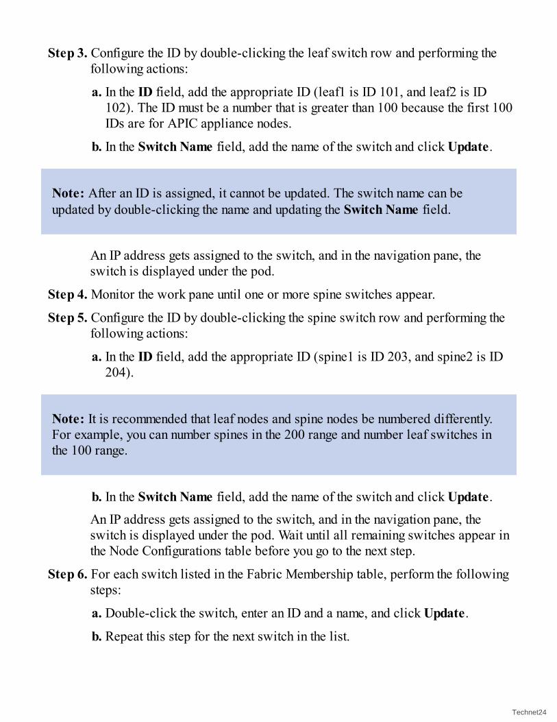
Step 3. Configure the ID by double-clicking the leaf switch row and performing thefollowing actions:
a. In the ID field, add the appropriate ID (leaf1 is ID 101, and leaf2 is ID102). The ID must be a number that is greater than 100 because the first 100IDs are for APIC appliance nodes.
b. In the Switch Name field, add the name of the switch and click Update.
Note: After an ID is assigned, it cannot be updated. The switch name can beupdated by double-clicking the name and updating the Switch Name field.
An IP address gets assigned to the switch, and in the navigation pane, theswitch is displayed under the pod.
Step 4. Monitor the work pane until one or more spine switches appear.
Step 5. Configure the ID by double-clicking the spine switch row and performing thefollowing actions:
a. In the ID field, add the appropriate ID (spine1 is ID 203, and spine2 is ID204).
Note: It is recommended that leaf nodes and spine nodes be numbered differently.For example, you can number spines in the 200 range and number leaf switches inthe 100 range.
b. In the Switch Name field, add the name of the switch and click Update.An IP address gets assigned to the switch, and in the navigation pane, theswitch is displayed under the pod. Wait until all remaining switches appear inthe Node Configurations table before you go to the next step.
Step 6. For each switch listed in the Fabric Membership table, perform the followingsteps:
a. Double-click the switch, enter an ID and a name, and click Update.
b. Repeat this step for the next switch in the list.
Technet24||||||||||||||||||||
||||||||||||||||||||

Fabric ExtendersFabric Extenders (FEXs) may be part of your ACI design. Similar to other Nexusproducts, Fabric Extenders in ACI must be configured after the parent switch isprovisioned and fully functional. Fabric Extenders are not included in the ACI fabriczero-touch provisioning. At press time the following is supported when using a FEXwith the ACI fabric:
Only straight-through attachment of a Fabric Extender to a leaf is supported. A license is required for each FEX device being used in ACI. Current scalability is 18 FEXs per leaf / 200 per fabric. Some FEX models can support both Fibre Channel over Ethernet (FCoE) and dataconnectivity.
The following FEX models are supported: N2K-C2232PP-10GE N2K-C2232TM-E-10GE N2K-C2348UPQ N2K-C2348TQ N2K-C2332TQ N2K-C2248TP-E-1GE N2K-C2248TP-1GE N2K-C2248PQ-10GE N2K-B22IBM-P N2K-B22DELL-P
However, because this list can be frequently updated, refer to the release notes of theNexus 9000 switch for the ACI software you use for an accurate and updated list.
A Fabric Extender in ACI can only be attached to a single leaf with one or more ports.The ports that connect the FEX to a leaf are able to be part of a port channel. Thefollowing is a link to a configuration example displaying the policy required toconfigure a Fabric Extender in ACI: https://tinyurl.com/FEXACI.
||||||||||||||||||||
||||||||||||||||||||

Required ServicesAt the beginning of the chapter, we reviewed suggested services. Within those services,NTP was listed as a required service due to the dependence of time synchronization inthe visibility, management, and troubleshooting functionalities that exist within ACI.Many enterprises have moved to ACI to leverage these features, which require NTP. Inthe following sections, we explore the three minimal tasks required to prepare a fabricto be production-ready, to accept policy, and to accept applications. We examine thesesteps in the Basic GUI and Advanced GUI separately due to differences in theirconfiguration. In each GUI, the tasks are the same:
1. Configure the management network.2. Configure NTP.
3. Configure the route reflectors.
Settings can be verified as tasks are completed. Advanced mode requires policies forcorrect operation. We explore the hierarchy and relationship of access policies in depth.Policies will also be used to configure the aforementioned required services.
Basic Mode Initial SetupThe Basic GUI has been streamlined to allow enterprises to use the most commonfeatures within ACI without learning and using the policy model. Following this sameapproach, the initial setup of the fabric has been streamlined as well. Once thefollowing sections have been completed, your fabric will be ready to accept policy,devices, and applications.
Management NetworkConfiguring the management network in the Basic GUI is quick and easy. The items youneed to configure can be found under the System menu and the In Band and Out of Bandsubmenus. In this section, we assume you are going to use out-of-band (OOB)management. When you highlight Out of Band Management Configuration in the leftnavigation pane, you will see configuration options to the right in the work pane. Usingthe work pane, you have the following options available:
Configure a node (switch/controller) with the OOB management IP address andgateway.
Technet24||||||||||||||||||||
||||||||||||||||||||

Configure an access restriction for which subnets can be used to interact with thepreviously configured management addresses.
Configure an access restriction for which protocols can be used to interact with thepreviously configured management addresses.
The only item that is required is to configure a node. If you do not configure additionalrestrictions, all communications will be allowed. It is a best practice to configureadditional access restrictions. You can find step-by-step configuration information in thedocument “Cisco APIC Basic Configuration Guide, Release 2.x” at Cisco.com.
Note: Be careful when adding nodes and restrictions that you don’t accidentlyprevent yourself from accessing the devices remotely.
If you want to configure in-band management, follow these steps:
Step 1. Log in to the Basic mode in the APIC GUI, and on the menu bar, click System> In Band & Out of Band.
Step 2. In the navigation pane, choose In-Band Management Configuration.
Step 3. (Optional) In the Encap field, enter a new value to change the default VLANthat is used for in-band management.
Step 4. Expand Nodes and perform the following actions:
a. In the Nodes field, choose the appropriate node to associate with the in-band address.
b. In the IP address field, enter the desired IPv4 or IPv6 address.
c. In the Gateway field, enter the desired IPv4 or IPv6 gateway address. ClickSubmit.
Note: The default gateway IP address will be the pervasive gateway of the ACIfabric on the VRF for the in-band management.
Step 5. Click the L2 Connectivity tab, expand Ports, and perform the followingactions:
a. In the Path field, from the drop-down list, choose the port that is connected
||||||||||||||||||||
||||||||||||||||||||

to a server for management or to the outside.
b. In the Encap field, specify a VLAN to use on this port.
Step 6. Expand Gateway IP Address for External Connectivity and in the IPaddress fields, list the desired gateway IPv4 and IPv6 addresses for externalconnectivity.
Step 7. Expand ACLs and add the desired ports you want to connect to the in-bandmanagement network. Click Submit.
NTPWe have covered the value of NTP in detail. To configure NTP, navigate to the Systemmenu and then to the System Settings submenu. Highlight NTP in the left navigationpane. In the work pane on the right you will see NTP configuration options. You havethe ability to modify these four items:
Description
Administrative State: Enable/Disable
Authentication: Enable/Disable
Add an NTP Server or Provider
First enable the administrative state. Next, add an NTP server using the plus sign on themiddle-right. A new window will open where you can add details regarding the NTPserver. You have the ability to modify these items:
Name: IP or hostname (requires DNS configuration)
Description
Preferred: If you have more than one server, which is the primary?
Minimum Polling Intervals and Maximum Polling Intervals
Management Network: Which management network will you use to communicatewith the NTP server?
Enter the IP address for the NTP server. Next, check the Preferred check box. Selectthe default OOB management network. Click Submit and then Submit again to save yoursettings.
Verifying your configuration is easy. Highlight NTP in the left navigation pane. In the
Technet24||||||||||||||||||||
||||||||||||||||||||

work pane on the right, double-click the NTP server you have configured. A newwindow will open up. Click the Operational tab in the upper-right. In the DeployedServers tab, you should now see the management IP addresses listed with their syncstatus.
Note: You may also want to explore the date-time settings to adjust the time offsetfor your time zone.
Route ReflectorsCisco ACI uses MP-BGP (Multiprotocol–Border Gateway Protocol) to distributeexternal routing information across the leaf switches in the fabric. Therefore, theinfrastructure administrator needs to define the spine switches that are used as routereflectors and the autonomous system number (ASN) that is used in the fabric.
The Cisco ACI fabric supports one ASN. The same ASN is used for internal MP-BGPand for the internal BGP (iBGP) session between the border leaf switches and externalrouters. Given that the same ASN is used in both cases when using iBGP, the user needsto find the ASN on the router to which the Cisco ACI border leaf connects and to use itas the BGP ASN for the Cisco ACI fabric.
To summarize, in order to perform Layer 3 routing in the fabric and connect externallyfrom the fabric over Layer 3, you need to configure route reflectors. You shouldconfigure at least two spines per pod as route reflectors for redundancy.
You can make the spine switches the route reflectors by configuring them as such underSystem > Systems Settings, as shown in Figure 3-7. Highlight BGP Route Reflectorin the navigation pane on the left side. In the work pane on the right side, you will beable to configure the following:
||||||||||||||||||||
||||||||||||||||||||

Figure 3-7 Configuring Spine Switches as Route Reflectors
Description
Autonomous System Number: This should be unique in your environment (forexample, 65001).
Route Reflector Nodes: Choose the spine nodes you want to be the route reflectors.
External Route Reflector Nodes: Used for Multi-Pod or WAN integration.
Enter the autonomous system number. Add the route reflector nodes by clicking the plusto the right of the Route Reflector Node window. Enter the device number of the spineyou want to configure as the route reflector. Click Submit. Repeat these actions for thenext spine node. Click Submit at the bottom-right of the page to save your changes.
Technet24||||||||||||||||||||
||||||||||||||||||||

VLAN DomainsIn spanning-tree networks, the user must specify which VLANs belong to which ports byusing the switchport trunk allowed VLAN command. In the Cisco ACI fabric, a VLANpool is used to define a range of VLAN numbers that will ultimately be applied onspecific ports (for hosts or network devices) on one or more leaf nodes. A VLAN poolcan be configured either as a static or a dynamic pool. Static pools are generally usedfor hosts and devices that will be manually configured in the fabric (for example, bare-metal hosts or L4-7 devices attached using traditional services insertion). Dynamicpools are used when the APIC needs to allocate VLANs automatically—for instance,when using VMM integration or automated services insertion (service graphs).
It is a common practice to divide VLAN pools into functional groups, as shown in Table3-4. It is a best practice to assign specific domains and pools to individual tenants.
Table 3-4 VLAN Pool Example
VLAN Range Type Use
1000–1100 Static Bare-metal hosts
1101–1200 Static Firewalls
1201–1300 Static External WAN routers
1301–1400 Dynamic Virtual machines
To configure a VLAN domain and pool in Basic mode, you would first navigate to theFabric menu and the Inventory submenu. In the navigation pane on the left, highlightVLAN Domains. Click the plus in the VLAN Domains work pane on the right. A newwindow will open. In this window, you can define the following:
Name: Name for the group of VLANs or VLAN domain you are configuring (forexample, Tenant1_Vmware_VDS, Tenant1_Physical, Tenant2_CheckpointFW, andso on).
Allocation Mode: Static or dynamic. Dynamic is normally used for automating Layer4-7 services and virtualization. Static is normally used for physical devices orconnectivity.
VLAN Range: The range of VLANs you would like to include in this domain. Youcan specify one or more.
Define the name (use underscores for spaces). Your allocation mode will most likely be
||||||||||||||||||||
||||||||||||||||||||

static to start with. Then click the plus sign to define a VLAN range. In the middle of thewindow, under VLAN Ranges, you will see the To and From field highlighted.Populate that field with the appropriate VLAN range for the devices you will beconnecting. The allocation mode can be left to Inherit from parent. Click Update andthen Submit. Repeat as necessary.
Advanced Mode Initial SetupThe Advanced GUI can sound intimidating at first. In reality, it is not harder to use orlearn than the Basic GUI; it just takes a little more time to learn how all the policyobjects relate to each other. Once you are familiar with the relationships and order ofoperations, it will become like second nature. When using the Advanced GUI, you doeverything with a policy. It is a best practice to leave the default policies in place andcreate new policies with names that make sense for your company and environment. Abyproduct of creating new policies is the ability to look at them and reference defaultconfigurations.
The naming convention you use for policies in the Advanced GUI is very important. Youwant it to be standardized, modular, and meaningful. How you name your policies willmake the difference between a streamlined administrative experience and a clutteredone. Table 3-5 shows best-practice recommendations regarding policy-namingconventions in ACI.
Table 3-5 ACI Policy-Naming Conventions (Best Practices)
Policy Name Examples
VRFs
[Function]_VRF Production_VRF
Bridge Domains
[Function]_BD Main_BD
Endpoint Groups
[Function]_EPG Web_EPG
Subnets
[Function]_SBNT App1_SBNT
Attachable Access Entity Profiles
Technet24||||||||||||||||||||
||||||||||||||||||||

[Function]_AEP VMM_AEPL3Out_AEP
VLAN Pools
[Function]_VLP VMM_VLPL3Out_VLP
Domains
[Functionality]_PHY[Functionality]_VMM[Functionality]_L2O[Functionality]_L3O
BareMetal_PHYvCenter1_VMML2DCI_L2OL3DCI_L3O
Contracts, Subjects, and Filters
[Tenant]_[Prov]_to_[cons]_CON Prod_Web_to_App_CON
[Rulegroup]_SUBJ WebTraffic_SUBJ
[Resource-Name]_FLT HTTP_FLT
Application Profiles
[Function]_ANP Prod_SAP_ANP
Interface Policies
[Type][Enable|Disable]_INTPOL CDP_Enable_INTPOLLLDP_Disable_INTPOL
Interface Policy Groups
[Type]_[Functionality]_IPG vPC_ESXi-Host1_IPGPC_ESXi-Host1_IPGPORT_ESXi-Host1_IPG
Interface Profiles
[Node1]_[Node2]_IPR 101_102_IPR
In Table 3-5, the policies are mainly named based on function. The policies also includea suffix that helps the administrator easily determine what type of policy they areworking with. This becomes vital as you start to leverage other forms of management,such as the API.
||||||||||||||||||||
||||||||||||||||||||

ACI was designed as a stateless architecture. The network devices have no application-specific configuration until a policy is defined stating how that application or trafficshould be treated on the network. Even then, the policy or configuration is notimplemented until you see interesting traffic that matches the policy, meaning that theindividual hardware, capabilities, and configuration are abstracted and what reallymatters is the intent of the policy. The two most frequent types of policy you will beconfiguring in ACI are access policies and tenant policies. These ACI policies can bethought of in two distinct ways: The access policies control the physical configurationof the individual switch ports. The tenant policies control the logical configuration ofthe fabric. An analogy can be made to a house. Think of the access policies like theexterior walls and foundation of the house, and the tenant policies like the interior wallsof a house. The walls and foundation are the support structure for the house, which needto be configured correctly to build a solid structure, and they don’t often change. Theinterior walls can and often do get changed and remodeled over the life of the house.The ACI fabric depends on the access policies to define how physical configurationshould be implemented on a port or group of ports once a tenant policy is applied. Atenant policy defines how that application or traffic should be treated once it hits thenetwork. You need to have both the physical and logical policies for the system to workcorrectly. This also makes it easy to leave physical connectivity, IP addressing, andVLANs in place, but dynamically change the tenant or logical policy at any time, asshown in Figure 3-8.
The policies we are exploring are also very modular. The planning that’s done up-frontwill quickly pay off in the future when, instead of re-creating a configuration over andover again, we are instead adding a port to a known-good policy. It takes time at thebeginning to learn this new way of doing things, but once you do, you will quickly seethe efficiencies (such as when you add a device to the fabric and it inherits the correctconfiguration).
Fabric policies are another type of policy that applies to the fabric (or fabrics) as awhole. These policies are usually configured once and then modified infrequently afterthat. The initial setup for services like NTP and the route reflectors will be configuredthrough these policies. Later, you can use these policies to change the settings acrossthat entire fabric (or fabrics) at a global level.
We explore these policy types further in the following sections.
Technet24||||||||||||||||||||
||||||||||||||||||||

Figure 3-8 Static Physical Configuration Mapping to Dynamic Policy
Access PoliciesGaining mastery over access policies is a crucial part of becoming proficient atconfiguring, managing, and troubleshooting ACI in Advanced mode. Access policies areresponsible for the physical configuration of the ports to which devices are attached.Access policies are configured in a hierarchical manner and built to be modular so thatyou can change isolated details without having to modify or re-create the entire policy.Once access policies are defined, the configuration stays dormant until a tenant policy istriggered. When the tenant policy is applied, the port is configured with the physicalcharacteristics defined in the access policy. Both policies are needed for ACI tofunction correctly.
Access policies are also created to simplify configuration and reduce human errorthrough the reuse of known-good policy. An engineer might create a single policy to useon all of their lights-out management ports, blade server connections, or rack-mountedESX servers. When you need to add a new server, you can just add a port to the existingbest-practice policy, thus eliminating configuration drift. You can also pre-stagepolicies on ports. For example, ports 1–5 on every switch may have access policiesconfigured for server management, just waiting for devices to be attached.
||||||||||||||||||||
||||||||||||||||||||

The hierarchical access policy relationships are defined in Figure 3-9. In theinformation that follows, we will be referencing the figure from left to right.
Figure 3-9 Access Policy Configuration Workflow
VLAN Pools and DomainsIn the Cisco ACI fabric, a VLAN pool is used to define a range of VLAN numbers thatwill ultimately be applied on specific ports on one or more leaf nodes. A VLAN poolcan be configured either as a static or a dynamic pool. Static pools are generally usedfor hosts and devices that will be manually configured in the fabric (for example, bare-metal hosts or L4-7 devices attached using traditional services insertion). Dynamicpools are used when the APIC needs to allocate VLANs automatically—for instance,when using VMM integration or automated services insertion (service graphs).
It is a common practice to divide VLAN pools into functional groups, as shown in Table3-6.
Table 3-6 VLAN Pool Example
VLAN Range Type Use
1000–1100 Static Bare-metal hosts
1101–1200 Static Firewalls
1201–1300 Static External WAN routers
1301–1400 Dynamic Virtual machines
A domain is used to define the scope of VLANs in the Cisco ACI fabric—in otherwords, where and how a VLAN pool will be used. There are a number of domain types:physical, virtual (VMM domains), external Layer 2, and external Layer 3. It is commonpractice to have a 1:1 mapping between a VLAN pool and a domain. It is also commonpractice to have separate VLAN pools and domains per tenant.
Technet24||||||||||||||||||||
||||||||||||||||||||

Attachable Access Entity ProfilesThe Attachable Access Entity Profile (AAEP) is used to map domains (physical orvirtual) to interface policies, with the end goal of mapping VLANs to interfaces.Configuring an AAEP is roughly analogous to configuring switchport access vlan x onan interface in a traditional NX-OS configuration. In addition, AAEPs allow a one-to-many relationship (if desired) to be formed between interface policy groups anddomains, as shown in Figure 3-10.
Figure 3-10 AAEP Relationships
In the example in Figure 3-10, an administrator needs to have both a VMM domain anda physical domain (that is, using static path bindings) on a single port or port channel.To achieve this, the administrator can map both domains (physical and virtual) to asingle AAEP, which can then be associated with a single interface policy grouprepresenting the interface and port channel.
||||||||||||||||||||
||||||||||||||||||||

Interface PoliciesInterface policies are responsible for the configuration of interface-level parameters,such as LLDP, Cisco Discovery Protocol, LACP, port speed, storm control, andMiscabling Protocol (MCP). Interface policies are brought together as part of aninterface policy group (described in the next section).
Each type of interface policy is preconfigured with a default policy. In most cases, thefeature or parameter in question is set to “disabled” as part of the default policy.
It is highly recommended that you create explicit policies for each configuration itemrather than relying on and modifying the default policy. For example, for LLDPconfiguration, it is highly recommended that you configure two policies—LLDP_Enabled and LLDP_Disabled (or similar)—and use these policies when eitherenabling or disabling LLDP. This helps prevent accidental modification of the defaultpolicy, which may have a wide impact.
Note: You should not modify the Interface Policy for “LLDP Interface” named“default” because this policy is used by spines and leaf nodes for bootup and tolook for an image to run. If you need to create a different default configuration forthe servers, you can create a new LLDP policy and give it a name, and then use thisone instead of the policy called “default.”
Interface Policy GroupsIn a Cisco ACI fabric, access ports, port channels, and VPCs are created using interfacepolicy groups. The interface policy group ties together a number of interface policies,such as Cisco Discovery Protocol, LLDP, LACP, MCP, and storm control. When you’recreating interface policy groups for port channels and VPCs, it is important tounderstand how policies can and cannot be reused. Consider the example shown inFigure 3-11.
Technet24||||||||||||||||||||
||||||||||||||||||||

Figure 3-11 vPC Interface Policy Groups
In this example, two servers are attached to the Cisco ACI leaf pair using VPCs. In thiscase, two separate interface policy groups must be configured, associated with theappropriate interface profiles (used to specify which ports will be used) and assignedto a switch profile. A common mistake is to configure a single interface policy group
||||||||||||||||||||
||||||||||||||||||||

and attempt to reuse it for multiple port channels or VPCs on a single leaf node.However, using a single interface policy group and referencing it from multipleinterface profiles will result in additional interfaces being added to the same portchannel or VPC, which may not be the desired outcome.
A general rule is that a port channel or VPC interface policy group should have a 1:1mapping to a port channel or VPC. Administrators should not try to reuse port channeland VPC interface policy groups for more than one port channel or VPC. Note that thisrule applies only to port channels and VPCs. For access port interface policy groups,these policies can be reusable.
It may be tempting for administrators to use a numbering scheme for port channels andVPCs (such as PC1, PC2, vPC1, and so on). However, this is not recommended becauseCisco ACI allocates an arbitrary number to the port channel or VPC when it is created,and it is unlikely that the numbering will match, which could lead to confusion. Instead,it is recommended that you use a descriptive naming scheme (for example,Firewall_Prod_A).
Interface ProfileInterface profiles exist in the ACI fabric to marry a port or a range of ports to a specificinterface policy group. As a best practice for configuration and troubleshooting, youshould name your interface profile the same as the switch with which you will beassociating the interface profile. An interface/leaf profile would then be created forevery leaf and every VPC pair in your ACI fabric, as shown in Figure 3-12.
Figure 3-12 Leaf Selector Profile
It is also a best practice to name your interface selectors the same as the port you areselecting. For instance, if you are selecting port 1/6, you would name the selector 1_6,as shown in Figure 3-13.
Technet24||||||||||||||||||||
||||||||||||||||||||

Figure 3-13 Interface Selectors
Once all of your policies are defined, configuring a port should be as simple as addingan interface selector to the interface profile and selecting which policy group toconsume.
Switch ProfileSwitch profiles specify from which ACI leaf your interface profiles will be selectinginterfaces. As with interface profiles, it is a best practice to define a switch profile foreach individual leaf and VPC pair in your fabric, as demonstrated in Figure 3-14.
Figure 3-14 Leaf Profiles
When a switch profile is defined, you will also choose to associate interface selectorprofiles, which should be very straightforward due to the fact that they share the samenaming convention.
||||||||||||||||||||
||||||||||||||||||||

Management NetworkAn Application Policy Infrastructure Controller has two routes to reach the managementnetwork: One is by using the in-band management interface, and the other is by using theout-of-band management interface.
The in-band management network allows the APIC to communicate with the leafswitches and with the outside using the ACI fabric, and it makes it possible for externalmanagement devices to communicate with the APIC or the leaf switches and spineswitches using the fabric itself.
The out-of-band management network configuration defines the configuration of themanagement port on the controllers, the leaf switches, and the spine switches.
To configure the management networks in the Advanced GUI, you will need to navigateto the Tenants menu item. The mgmt (management) tenant contains all the configurationdetails for both the in-band and out of band networks. To enter the mgmt tenant, double-click it. For this example, we are going to configure an out-of-band network. In theAdvanced GUI, you have the ability to assign static addresses or use a pool ofaddresses that are automatically assigned. It is a best practice to use the pool ofaddresses. When you use a pool, a new switch that is added to the fabric isautomatically assigned an address and can utilize existing policies that are in place,with no user intervention. To configure the out-of-band network, follow these steps:
Step 1. In the navigation pane, expand the tenant mgmt.
Step 2. Right-click Node Management Addresses and click Create NodeManagement Addresses.
Step 3. In the Create Node Management Addresses dialog, perform the followingactions:
a. In the Policy Name field, enter a policy name (switchOob).
b. In the Nodes field, check the boxes next to the appropriate leaf and spineswitches (leaf1, leaf2, and spine1).
c. In the Config field, check the box next to Out-of-Band Addresses.
Note: The Out-of-Band IP Addresses area is displayed.
d. In the Out-of-Band Management EPG field, choose the EPG from the
Technet24||||||||||||||||||||
||||||||||||||||||||

drop-down list (default).
e. In the Out-of-Band IP Addresses and Out-of-Band Gateway fields, enterthe desired IPv4 or IPv6 addresses that will be assigned to the switches.Click OK.
The node management IP addresses are configured. You must configure out-of-bandmanagement access addresses for the leaf and spine switches as well as for APIC.
Step 4. In the navigation pane, expand Node Management Addresses and click thepolicy you created. In the work pane, the out-of-band management addressesare displayed against the switches.
Step 5. In the navigation pane, expand Security Policies > Out-of-Band Contracts.
Step 6. Right-click Out-of-Band Contracts and click Create Out-of-BandContract.
Step 7. In the Create Out-of-Band Contract dialog, perform the following tasks:
a. In the Name field, enter a name for the contract (oob-default).
b. Expand Subjects. In the Create Contract Subject dialog, in the Name field,enter a subject name (oob-default).
c. Expand Filters, and in the Name field, from the drop-down list, choose thename of the filter (default). Click Update and then click OK.
d. In the Create Out-of-Band Contract dialog, click Submit.An out-of-band contract that can be applied to the out-of-band EPG is created.
Step 8. In the navigation pane, expand Node Management EPGs > Out-of-BandEPG-default.
Step 9. In the work pane, expand Provided Out-of-Band Contracts.
Step 10. In the OOB Contract column, from the drop-down list, choose the out-of-bandcontract you created (oob-default). Click Update and then click Submit. Thecontract is associated with the node management EPG.
Step 11. In the navigation pane, right-click External Network Instance Profile andclick Create External Management Entity Instance.
Step 12. In the Create External Management Entity Instance dialog, perform thefollowing actions:
a. In the Name field, enter a name (oob-mgmt-ext).
||||||||||||||||||||
||||||||||||||||||||

b. Expand the Consumed Out-of-Band Contracts field. From the Out-of-Band Contracts drop-down list, choose the contract that you created (oob-default). Click Update. Choose the same contract that was provided by theout-of-band management.
c. In the Subnets field, enter the subnet address. Click Submit. Only the subnetaddresses you choose here will be used to manage the switches. The subnetaddresses that are not included cannot be used to manage the switches.
The node management EPG is attached to the external network instance profile. The out-of-band management connectivity is configured.
Note: You can make out-of-band management access the default managementconnectivity mode for the APIC server by clicking Fabric > Fabric Policies >Global Policies > Connectivity Preferences. Then, on the ConnectivityPreferences page, click ooband.
Note: The APIC out-of-band management connection link must be 1Gbps.
Fabric PoliciesFabric policies are found on the main Fabric tab in the APIC GUI and are concernedwith configuration of the fabric itself (for example, IS-IS, management access, MP-BGP,and fabric MTU). Many of the policies found in this section should not be modifiedunder normal circumstances, and the recommendation is to not change them. However,there are a number of policies that deserve consideration and are therefore covered inthis section.
NTPWithin the Cisco Application Centric Infrastructure (ACI) fabric, time synchronizationis a crucial capability upon which many of the monitoring, operational, andtroubleshooting tasks depend. Clock synchronization is important for proper analysis oftraffic flows as well as for correlating debug and fault timestamps across multiplefabric nodes.
Technet24||||||||||||||||||||
||||||||||||||||||||

An offset present on one or more devices can hamper the ability to properly diagnoseand resolve many common operational issues. In addition, clock synchronization allowsfor the full utilization of the atomic counter capability that is built in to the ACI, uponwhich the application health scores depend.
The procedure for configuring NTP in the Advanced GUI is as follows:
Step 1. On the menu bar, choose Fabric > Fabric Policies.
Step 2. In the navigation pane, choose Pod Policies > Policies.
Step 3. In the work pane, choose Actions > Create Date and Time Policy.
Step 4. In the Create Date and Time Policy dialog, perform the following actions:
a. Enter a name for the policy to distinguish between the different NTPconfigurations in your environment. Click Next.
b. Click the plus sign to specify the NTP server information (provider) to beused.
c. In the Create Providers dialog, enter all relevant information, including thefollowing fields: Name, Description, Minimum Polling Intervals, andMaximum Polling Intervals.
If you are creating multiple providers, check the Preferred check box for themost reliable NTP source.
In the Management EPG drop-down list, if the NTP server is reachable by allnodes on the fabric through out-of-band management, choose Out-of-Band. Ifyou have deployed in-band management, see the details about In-BandManagement NTP. Click OK.Repeat the steps for each provider you want to create.
Step 5. In the navigation pane, choose Pod Policies > Policy Groups.
Step 6. In the work pane, choose Actions > Create Pod Policy Group.
Step 7. In the Create Pod Policy Group dialog, perform the following actions:
a. Enter a name for the policy group.
b. In the Date Time Policy field, from the drop-down list, choose the NTPpolicy that you created earlier. Click Submit. The pod policy group iscreated. Alternatively, you can use the default pod policy group.
Step 8. In the navigation pane, choose Pod Policies > Profiles.
||||||||||||||||||||
||||||||||||||||||||

Step 9. In the work pane, double-click the desired pod selector name.
Step 10. In the Properties area, from the Fabric Policy Group drop-down list, choosethe pod policy group you created. Click Submit.
Route ReflectorsThe BGP route reflector policy controls whether MP-BGP runs within the fabric andwhich spine nodes should operate as BGP reflectors. When a Cisco ACI fabric isinitially provisioned, MP-BGP is not enabled inside the fabric. However, in themajority of cases, MP-BGP must be enabled to allow the distribution of external routinginformation throughout the fabric.
It is important to note that the BGP autonomous system number (ASN) is a fabric-wideconfiguration setting that applies across all Cisco ACI pods that are managed by thesame APIC cluster and should be unique in your environment (Multi-Pod).
To enable and configure MP-BGP within the fabric, modify the BGP Route Reflectordefault policy under Pod Policies on the Fabric Policies tab. The default BGP routereflector policy should then be added to a pod policy group and pod profile to make thepolicy take effect.
Managing Software VersionsMany hours have been spent during maintenance windows upgrading individualswitches one by one. Cisco ACI makes the traditional method of managing devicefirmware a thing of the past. The Cisco APICs are looking at the network as a singleentity or fabric and not as a bunch of individual devices. ACI has consolidated thesoftware image management for the entire fabric, as well as the controllers, andwrapped it in a process that is easy to administer. We examine each of the parts of thefirmware management process separately in the sections that follow. At a high level, thesteps to upgrade or downgrade the ACI fabric are as follows:
Note: The procedure/steps for upgrading and downgrading are the same unlessstated otherwise in the release notes of a specific release.
Step 1. Download the ACI Controller image (APIC image) into the repository.
Technet24||||||||||||||||||||
||||||||||||||||||||

Step 2. Download the ACI switch image into the repository.
Step 3. Upgrade the ACI controller cluster (APICs).
Step 4. Verify the fabric is operational.
Step 5. Divide the switches into multiple groups (for example, divide into two groups:red and blue).
Step 6. Upgrade the red group of switches.
Step 7. Verify the fabric is operational.
Step 8. Upgrade the blue group of switches.
Step 9. Verify the fabric is operational.
Additionally, here are some general guidelines regarding ACI fabricupgrade/downgrade:
Divide switches into two or more groups. Upgrade one group at a time. That way,you will maintain connectivity for your redundant servers and not lose fabricbandwidth entirely during the upgrade window.
Do not upgrade or downgrade nodes that are part of a disabled configuration zone. Unless specified otherwise in release notes of a specific release, you can upgrade(or downgrade) controllers before switches, and vice versa (switches beforecontrollers).
A specific release, or a combination of releases, may have some limitations andrecommendations for the upgrade or downgrade procedure. Double-check therelease notes for the release before upgrading or downgrading your ACI fabric. If nosuch limitations or recommendations are specified in the release notes, theaforementioned steps should be followed to upgrade or downgrade your ACI fabric.
Firmware RepositoryThe ACI firmware repository is a distributed store that houses firmware imagesrequired to upgrade or downgrade the ACI fabric. The firmware repository is synced toevery controller in the cluster. A firmware image is downloaded into the firmwarerepository from an external server (HTTP or SCP) when a download task is configured.Another option is to upload the firmware from a folder on your local machine via anupload task. Three types of firmware images can be stored in the repository:
||||||||||||||||||||
||||||||||||||||||||

Controller/APIC image: This image consists of software that runs on ACIcontrollers (APICs).
Switch image: This image consists of software that runs on ACI switches.
Catalog image: This image consists of Cisco-created internal policies. Theseinternal policies contain information about the capabilities of different models ofhardware, the compatibility across different versions of software, and the hardwareand diagnostic tests. This image is usually bundled and upgraded along with thecontroller image. Unless specifically instructed by the release notes of a specificrelease, an administrator should never have to individually upgrade a catalog image.
The firmware will be added to the repository in two separate tasks. The first task is forthe controller software to be added to the repository and replicated across thecontrollers. Second, the switch image will be uploaded to the repository and replicatedacross the controllers. The catalog image is a part of the controller image and will beadded to the repository when the controller image is added.
To check the status of your tasks, perform the following steps:
Step 1. In the navigation pane, click Download Tasks.
Step 2. In the work pane, click Operational to view the download status of theimages.
Step 3. Once the download reaches 100% in the navigation pane, click FirmwareRepository. In the work pane, the downloaded version numbers and imagesizes are displayed.
Controller Firmware and Maintenance PolicyThe controller firmware policy specifies the desired version of software forcontrollers. Once the controller software is in the firmware repository, the controllersoftware policy can be modified to reflect the target software version to which youwould like to upgrade or downgrade. The controller maintenance policy specifies whenthe upgrade of controllers should start. The controller firmware policy and thecontroller maintenance policy apply to all the controllers in the cluster. The steps toperform a software upgrade are as follows:
Step 1. In the navigation pane, click Controller Firmware. In the work pane, chooseActions > Upgrade Controller Firmware Policy. In the Upgrade ControllerFirmware Policy dialog, perform the actions specified in step 2.
Technet24||||||||||||||||||||
||||||||||||||||||||

Step 2. In the Target Firmware Version field, from the drop-down list, choose theimage version to which you want to upgrade. In the Apply Policy field, clickthe radio button for Apply now. Click Submit. The Status dialog displays the“Changes Saved Successfully” message, and the upgrade process begins. TheAPICs are upgraded serially so that the controller cluster is available duringthe upgrade.
Step 3. Verify the status of the upgrade in the work pane by clicking ControllerFirmware in the navigation pane.
Note: The controllers upgrade in random order. Each APIC takes at least 10minutes to upgrade. Once a controller image is upgraded, it drops from the cluster,and it reboots with the newer version while the other APICs in the cluster are stilloperational. Once the controller reboots, it joins the cluster again. Then the clusterconverges, and the next controller image starts to upgrade. If the cluster does notimmediately converge and is not fully fit, the upgrade will wait until the clusterconverges and is fully fit. During this period, a “Waiting for Cluster Convergence”message is displayed in the Status column for each APIC as it upgrades.
Note: When the APIC that the browser is connected to is upgraded and it reboots,the browser displays an error message.
Step 4. In the browser’s URL field, enter the URL for the APIC that has already beenupgraded and then sign in to the controller as prompted.
Firmware Groups and PolicyA firmware group is how ACI groups the switches in the fabric to which you configure afirmware policy. A firmware policy specifies the desired firmware version for switchesin the group. In other words, we are declaring all of these switches belong at thisfirmware level. Typically, all of the switches in a single fabric will belong to the samefirmware group. However, these policies give you the capability to create multiplegroups of switches that have different firmware policies or target firmware versions.These policies are merely responsible for determining software versions. Makingchanges to these policies will not trigger an upgrade.
||||||||||||||||||||
||||||||||||||||||||

Maintenance Group and Maintenance PolicyA maintenance group is a group of switches on which you would configure amaintenance policy. A maintenance policy specifies a schedule for upgrade. Themaintenance policy acts on the previously defined firmware groups and policies.Maintenance groups allow enterprises to perform upgrades across the fabric inmanageable portions on an ad-hoc or scheduled basis. Furthermore, if the devices thatare connected to your fabric are done so redundantly, maintenance groups give you theability to perform upgrades with little to no disruption to production data. Mostcustomers use the two-group method, as follows:
Step 1. Divide your switches into two groups: a red group and a blue group. Put onehalf of the spines in the red group and the other half in the blue group. Also, putone half of the leaf switches in the red group and the other half in the bluegroup.
Step 2. Upgrade the red group.
Step 3. After the red group upgrade is complete, confirm the fabric is healthy.
Step 4. Upgrade the blue group.
Customers that are very risk adverse might opt for the four-group method:
Step 1. Divide your switches into four groups: a red spines group, a blue spines group,a red leaf switches group, and a blue leaf switches group. Put one half of thespines in the red spines group and the other half of the spines in the blue spinesgroup. Then, place half the leaf switches in the red leaf switches group and theother half in the blue leaf switches group.
Step 2. Upgrade the red leaf switches group.
Step 3. After the red leaf switches group upgrade is complete, confirm the fabric ishealthy.
Step 4. Upgrade the blue leaf switches group.
Step 5. After the blue leaf switches group upgrade is complete, confirm the fabric ishealthy.
Step 6. Upgrade the red spines group.
Step 7. After the red spines group upgrade is complete, confirm the fabric is healthy.
Step 8. Upgrade the blue spines group.
As you can see, the four-group method lengthens the procedure and time to perform the
Technet24||||||||||||||||||||
||||||||||||||||||||

upgrade. Enterprises will have to make their own decisions on which upgrade processbest fits their environment.
Using the SchedulerThe scheduler enables you to specify a window of time for operations such as upgradingAPIC clusters and switches. The windows of time can be “one time only” or recur at aspecified time and day each week. This section explains how the scheduler works forupgrades. For more information about the scheduler, see the “Cisco Application CentricInfrastructure Fundamentals” document.
Note: When you’re performing a cluster upgrade, the APICs must all be the sameversion for them to join the cluster. There is no automatic upgrade when joining thefabric.
Maintenance windows are a common event in most IT organizations. The scheduler canautomatically start both cluster upgrades and switch upgrades. The following discusseseach of these processes in more detail:
APIC cluster upgrade: There is a default scheduler object for APIC upgrades.Although the generic scheduler object has several properties, only the start timeproperty is configurable for the APIC cluster upgrade. If you specify a start time, theAPIC upgrade scheduler is active from the specified start time for the duration of 1day. Any time during this active one-day window, if runningVersion !=desiredVersion for the controllers, the cluster upgrade will begin. None of the otherparameters of the scheduler are configurable for APIC upgrades. Note that you canalso perform an APIC upgrade by using a one-time trigger, which does not use thescheduler. This one-time trigger is also called upgrade-now.
Switch upgrades: A scheduler may be attached to a maintenance group. A schedulerattached to a switch maintenance group has several configurable parameters, such asthe following:
startTime: The start of an active window
concurCap: The number of nodes to upgrade simultaneously
Duration: The length of an active window
Any time during an active window, if runningVersion != desiredVersion for any switch
||||||||||||||||||||
||||||||||||||||||||

in that group, the switch will be eligible for an upgrade. Among nodes eligible for anupgrade, the following constraints are applied to picking upgrade candidates:
No more than the concurCap nodes should currently be upgrading. Only one node in a VPC pair is upgraded at a time. The APIC cluster should be healthy before starting a node upgrade.
Configuration ManagementACI provides significant benefits over traditional architectures in the realm ofconfiguration management. It has never been easier to back up and maintainconfiguration across all of the devices in your data center. A feature in ACI calledConfiguration Snapshots allows snapshots of configurations to be taken on an ad-hoc orscheduled basis in a matter of seconds. These known-good configurations can becompared and rolled back just as fast. Imagine that before a maintenance window, asnapshot is taken. During the maintenance window, it is decided that the changes need tobe rolled back, and this process is executed with just a couple clicks. This can be donein just seconds. If you are using this chapter to configure or deploy your first ACI fabric,now would be a great time to perform a backup, so you have a clean slate to revert backto in case of a configuration issue. In the sections that follow, we examine configurationmanagement in greater detail.
Configuration SnapshotsConfiguration snapshots are configuration backup archives, stored (and replicated) in acontroller managed folder. ACI has the ability to take snapshots of the fabricconfiguration at two levels:
Fabric Individual tenants
These snapshots are grouped independently of each other and can be compared forconfiguration differences or rolled back at any time. Here are some of the actions thesystem will take when a snapshot is rolled back:
Deleted managed objects are re-created. Created managed objects are deleted.
Technet24||||||||||||||||||||
||||||||||||||||||||

Modified managed objects are reverted to their prior state.
Snapshots can be stored either on the APICs or sent to a remote location. Once thesnapshots are sent off box, you can then re-import the configurations at any time. Importand export security settings using AES-256 encryption can be configured via a 16-to-32character passphrase to safeguard your information. ACI also has the capability toschedule reoccurring snapshots on a schedule set by the administrator, as shown inFigure 3-15.
Figure 3-15 Automatically Create Snapshots on a scheduled basis
Configuration snapshots are available in both the Basic and Advanced GUI. Snapshotsdo not back up the entire APIC configuration. To back up the entire configuration, weneed to look at configuration backups.
Configuration BackupAll APIC policies and configuration data can be exported to create backups. This isconfigurable via an export policy that allows either scheduled or immediate backups toa remote server. Scheduled backups can be configured to execute periodic or recurringbackup jobs. By default, all policies and tenants are backed up, but the administratorcan optionally specify only a specific subtree of the management information tree.Backups can be imported into the APIC through an import policy, which allows thesystem to be restored to a previous configuration.
Figure 3-16 shows how the process works for configuring an export policy.
The APIC applies this policy in the following way:
1. A complete system configuration backup is performed once a month.2. The backup is stored in XML format on the BigBackup FTP site.
||||||||||||||||||||
||||||||||||||||||||

3. The policy is triggered (it is active).
Note: To manage your configuration backup, navigate to Admin > Import/Export.In the navigation pane on the left you will find Export Policies. It is here that youwill also find policies to export information for TAC if the need arises.
Figure 3-16 Configuring an Export Policy
Being able to restore your configuration is as important as backing it up. Anadministrator can create an import policy that performs the import in one of thefollowing two modes:
Best-effort: Ignores objects within a database shard (partition of data) that cannotbe imported. If the version of the incoming configuration is incompatible with theexisting system, the database shards that are incompatible are not imported while theimport proceeds with those that can be imported.
Technet24||||||||||||||||||||
||||||||||||||||||||

Atomic: Ignores database shards (partition of data) that contain objects that cannotbe imported while proceeding with shards that can be imported. If the version of theincoming configuration is incompatible with the existing system, the importterminates.
An import policy supports the following combinations of mode and type:
Best-effort merge: The imported configuration is merged with the existingconfiguration, and objects that cannot be imported are ignored.
Atomic merge: The imported configuration is merged with the existingconfiguration, and shards that contain objects that cannot be imported are ignored.
Atomic replace: Overwrites the existing configuration with imported configurationdata. Any objects in the existing configuration that do not exist in the importedconfiguration are deleted. Objects are deleted from the existing configuration thathave children in the existing configuration but do not have children in the incomingimported configuration. For example, if an existing configuration has two tenants(“solar” and “wind”), but the imported backed-up configuration was saved beforethe tenant “wind” was created, tenant “solar” is restored from the backup but tenant“wind” is deleted.
Figure 3-17 shows how the process works for configuring an import policy.
||||||||||||||||||||
||||||||||||||||||||

Figure 3-17 Configuring an Import Policy
The APIC applies this policy in the following way:
1. A policy is created to perform a complete system configuration restore frommonthly backup.
2. The atomic replace mode does the following:
a. Overwrites the existing configuration.
b. Deletes any existing configuration objects that do not exist in the imported file.
c. Deletes children objects that do not exist in the imported file.
3. The policy is untriggered (it is available but has not been activated).
Technet24||||||||||||||||||||
||||||||||||||||||||

SummaryACI is a full-featured and scalable data center fabric that enables security andperformance for applications and services. Delivering the critical features for next-generation data center networks, ACI is designed with the following requirements:resiliency, virtualization, efficiency, and extensibility. When the fabric was built isimportant to understand in order to enable foundational features and requirements.
This chapter covered the following topics:
The services that are suggested and required for a production ACI fabric. Management networks are needed for the support of a production network. ACIsupports both in-band and out-of-band management networks.
Application Policy Infrastructure Controllers (APICs) use a quick-and-easy setupscript. It is important to choose the right input for the infrastructure network andVLAN.
ACI supports multiple interfaces for configuration. When using the GUI, you willhave the option of Basic or Advanced.
How to configure required services in both Basic and Advanced mode. Becoming an expert in ACI requires understanding the policy that drives theconfiguration. Advanced mode access and fabric policies were explained.
Production networks require software and configuration management. This chapterexplored firmware maintenance policies as well as configuration archival androllback.
Controlling and managing access to network resources is critical for a productionnetwork. ACI supports in depth role-based access control (RBAC).
With this information, you’ll find it easy to get started building and exploring an ACIfabric.
||||||||||||||||||||
||||||||||||||||||||

Chapter 4
Technet24||||||||||||||||||||
||||||||||||||||||||

Integration of VirtualizationTechnologies with ACI
In this chapter, you will learn the following:
The benefits for virtualization and network professionals of integrating Cisco ACIand virtualization technologies
Deep dive into the integration with VMware vSphere, Microsoft System CenterVirtual Machine Manager, OpenStack, Docker containers, and Kubernetes
Design recommendations and caveats when integrating Cisco ACI with virtualizationtechnologies
Why Integrate Cisco ACI with VirtualizationTechnologies?Unless you have been living under a rock for the last 15 years, your organization hasmost likely adopted server virtualization in your data center. This means that some ofyour servers have virtualization software installed, and the virtual machines (VMs)running there are not directly connected to a traditional physical switch, but to thevirtual switch inside of the hypervisor.
In the last few years, an additional technology has strongly emerged that also makes useof virtual switches: Linux containers (often called “Docker” containers, after thecompany that created a simplified way of managing Linux containers), favored by otherindustry trends such as micro-services application architectures and the DevOpsparadigm.
Integrating Cisco ACI with virtualization technologies will bring the followingsignificant benefits for the virtualization administrator:
||||||||||||||||||||
||||||||||||||||||||

Network virtualization, or the possibility of programmatically deploying andconfiguring networking policies for virtual machines.
Additional network functionality, such as inter–data center connectivity, multi-tenancy, and micro-segmentation.
No need to learn networking. Cisco ACI makes sure that virtual workloads haveconsistent network policies with the rest of the data center.
Quicker resolution of network issues. Because the management and troubleshootingof the entire network is done centrally, identifying network problems and fixing themis much easier, as opposed to having to deal with different consoles for the virtualand physical networks.
Network management processes (such as adding new virtual switches and backingup virtual switch configurations) are taken care of by the network administrator,using Cisco ACI tools.
Virtualization admins also have the possibility of deploying virtual networks withoutinvolving the network team, directly from their virtualization console (such asvCenter in the case of VMware vSphere or Horizon in the case of OpenStack).
Similarly, the network administrator can also greatly benefit from the integration ofCisco ACI with virtual networking environments:
Cisco ACI is significantly augmented with information about all endpoints in the datacenter, including virtual machines and Docker containers. This dramaticallyimproves available network insights.
This additional information is very relevant, for example, when troubleshootingnetwork issues whose root cause may lie in the virtual or physical parts of thenetwork. Using Cisco ACI’s native tools, such as the Troubleshooting Wizard andthe Endpoint Tracker, for all workloads in a data center can help to shorten the timeit takes to fix networking problems.
It is now much easier to deploy consistent network policies across the whole datacenter, independent of the form factor of the application workloads.
Bandwidth management is more accurate because the network is aware of all trafficflows, including those involving virtual machines and Docker containers.
The following sections go into much more detail about these benefits.
Technet24||||||||||||||||||||
||||||||||||||||||||

Networking for Virtual Machines and ContainersServer virtualization and Linux containers are very important technologies that canincrease efficiencies for the data center, but at the same time they can pose challengesfor the network administrator. The main reason is that both server virtualization andLinux containers are not purely compute technologies, but they have an importantnetworking aspect to them that needs to be operated and managed.
Essentially, the network architecture of virtual machines and containers is similar: Bothare entities that live inside of a physical host (ignoring for a moment the possibility ofnested virtualization), and both have their own MAC and IPv4 or IPv6 addresses. Theunderlying operating system has a fixed set of physical network interfaces that need tobe shared across all the existing virtual machines.
Note that we are somewhat oversimplifying here because there are fundamentaldifferences between container and virtual machine networking. For example, containersdo not have their own TCP stack but use just a namespace in the host networking stack,comparable to virtual routing and forwarding (VRF) in a router, whereas virtualmachines bring their own Transmission Control Protocol (TCP) stack, completelyseparate from the one in the hypervisor. However, these differences do not affect theessence of the discussion in this section.
Most virtualization and container technologies provide networking to logical computeinstances (virtual machines or containers) by means of virtual switches that exist insidethe operating system, as Figure 4-1 shows. Whereas the physical network interfacecards (NICs) of the physical host are connected to traditional switches over real cables(represented by the black lines in the figure), connectivity to the virtual switch(represented by the gray lines) is typically controlled by the virtualization software andcan be dynamically modified.
||||||||||||||||||||
||||||||||||||||||||

Figure 4-1 Overall Network Architecture in a Hypervisor
This setup presents some challenges:
Who should manage the virtual switch inside the physical host? Some virtualizationadministrators might be equally capable of managing networks as well. However, inmany cases, complex network configurations, including concepts such assophisticated network security and quality of service (QoS), are not their core fieldof expertise.
Is the network policy for virtual and physical machines consistent? Virtual switchesembedded in the hypervisor might have different functionality than purpose-builtEthernet switches, whose software and hardware have evolved over the last twodecades. However, from a network and security standpoint, all workloads in thedata center should have consistent policies. How does one achieve this consistencywith different software capabilities and management concepts?
How does one manage and troubleshoot the network holistically? The network isoften the first point where people tend to look for culprits upon any incident in thedata center. However, having two (or more) different sets of tools to manage andtroubleshoot different parts of the network does not necessarily make finding theroot cause of a network problem easier.
Technet24||||||||||||||||||||
||||||||||||||||||||

Additionally, the situation might grow even more complex when additionalvirtualization vendors and technologies are introduced. For example, Figure 4-2 depictsan example with diverse technologies such as network virtualization, Linux containers,and bare-metal servers coexisting in the same network.
Figure 4-2 Coexistence of Different Technologies from a Network Perspective
In this case, you would have at least three different networks to manage andtroubleshoot individually: the physical switches, the virtual switches inside of yourhypervisors, and the virtual switches inside of your Linux container hosts. If on top ofthat you have multiple hypervisor vendors (most companies out there have a dual-hypervisor strategy) and multiple container frameworks (because containers are still anascent technology, chances are that your IT departments will be using more than onecontainer framework as they mature), the situation becomes really challenging.
In the worst case, you would have to individually assess the capabilities of each virtualswitch, have different processes for network management, depending on the workload,and have different network and security policies for applications that are deployed inbare-metal servers, in virtual machines, and in containers.
||||||||||||||||||||
||||||||||||||||||||

Benefits of Cisco ACI Integration with Virtual SwitchesCisco ACI can alleviate the problems described above. As previous chapters haveexplained, the Cisco ACI concept is based on a centralized repository, located in theApplication Policy Infrastructure Controllers (APICs), that distributes network policy toindividual switches.
It is only natural extending this concept so that network policy is not only deployed tophysical switches but to virtual ones located in hypervisors or Linux container hosts aswell. This way, network and security policy for a workload is independent of its formfactor (bare metal, virtual machine, or Linux container), and the network can bemanaged holistically:
If an application workload is migrated to a different form factor (for example, from avirtual machine to a container, or from one hypervisor to another), the systemadministrator does not need to reinvent the proverbial “network wheel” in the newplatform because the previous network policy will consistently apply in the newhypervisor as well.
Network troubleshooting is greatly improved, by providing a single pane of glass forall workloads. Locating the root cause for problems is easier because networkadministrators can look at network flows, end to end, and not only in siloes.
Network management becomes much simpler because all network information for allworkloads in a data center is contained in a single repository, with consistentapplication programming interfaces (APIs) and software development kits (SDKs).
Should the network configuration change for a certain workload—for example,because of new regulatory requirements—the corresponding policy only needs to bechanged once. This single policy repository makes finding policy inconsistencieseasier, in case virtual and physical switches have conflicting configurations, such asthe allowed VLANs and the Etherchannel mode.
Note that one key element of the Cisco ACI architecture that enables configuringdisparate data planes (physical switches and virtual switches for different hypervisors)with the same policy is the declarative character of the OpFlex protocol, the mechanismused to distribute policy to the switches in the ACI fabric. Other networkingframeworks that use imperative models to configure the individual fabric elements aremore difficult to integrate with heterogeneous data planes. Refer to the section“OpFlex,” later in this chapter, for more details on this aspect of the ACI architecture.
To illustrate the power of combining a single network policy across multiple workloadform factors, Figure 4-3 shows an example of an application profile in a Cisco ACI
Technet24||||||||||||||||||||
||||||||||||||||||||

fabric, where the Database instances are bare-metal servers (represented by the letter Bin the lower part of the canvas), and the Web instances can be either VMware orMicrosoft virtual machines (represented by the letters V and M, respectively). Note thatthis is only an example, and many other combinations are possible, includingKubernetes containers (letter K), OpenStack instances (letter O), and Red HatVirtualization virtual machines (letter R).
Figure 4-3 A Sample Application Profile with Multiple Integrations
In this example, the network policy was decided independently of the workload types,at application design time. ACI contracts, application tiers, and external connectivityare specified for an architecture without you having to know in advance details such ason which hypervisor the architecture will be deployed.
Thus, the decision of whether to use physical servers, virtual machines, or even Dockercontainers can be taken up at a later stage, with the assurance that the previously definednetwork policies will be respected.
||||||||||||||||||||
||||||||||||||||||||

Comparing ACI Integration to Software NetworkOverlaysThe same way that the management plane in traditional networks has evolved from adistributed approach into a modern centralized concept like Cisco ACI, hypervisorvendors have developed concepts to centrally manage virtual switches.
For virtual switches that work only at Layer 2 of the ISO/OSI model (that is, withoutany IP functionality), hypervisor vendors came across a fundamental problem: how tocreate network segments across multiple hypervisors, without having to manage thephysical network? And this is where some of those vendors turned to encapsulationtechnologies such as Virtual Extensible LAN (VXLAN).
Encapsulation technologies are not new in the network industry. For example,Multiprotocol Label Switching (MPLS) is an encapsulation protocol that many networkadministrators have been using for years to create network overlays. The maindifference here is that the tunnel endpoints (TEPs) of the overlay tunnels in this case arenot traditional network devices but rather virtual switches inside of hypervisor hosts—hence, the name software network overlay.
Figure 4-4 shows the basic concept: network segments (broadcast domains) are createdin virtual switches and are made available to virtual machines in other hypervisors aswell. Virtual switches are interconnected to each other using VXLAN tunnels,essentially encapsulating the VM traffic in a UDP packet sourced from one hypervisorand addressed to another. Therefore, the physical network only sees the IP addresses ofthe physical hosts (that is, the tunnel endpoints), and not those of the virtual machines (inthe payload of the VXLAN packet inside of the tunnel). When connectivity with otherworkloads outside of the overlay is required, a gateway will bridge or route traffic fromthe VXLAN-based overlay to the physical network connected to the outer world.
Technet24||||||||||||||||||||
||||||||||||||||||||

Figure 4-4 Generic Architecture of Software Network Overlays
As the previous discussion made apparent, software-based overlays solve a specificproblem for a specific platform. If you are using, say, VMware vSphere ESXi as ahypervisor, you can have consistent management for your VMware virtual switchesusing one of VMware’s software network overlays, such as NSX for vSphere.However, you will be using a different management plane for the rest of the network,including your physical hosts, your Linux containers, other hypervisors such asMicrosoft Hyper-V or Red Hat Virtualization, or even with different versions of thevSphere hypervisor that support other incompatible software overlays (such as NSX forMulti-Hypervisor or the recently announced NSX-T).
A centralized network policy that covers all the workloads in a data center has manyadvantages over software network overlays:
The hypervisor admin does not need to learn networking. Most software networkoverlays need to replicate complex network structures such as routing protocols,load balancing, and network security inside of the hypervisor. This, in turn, demandsfrom the hypervisor administrator that they be an expert on these fields too.
Management and troubleshooting consistency, as explained earlier in this chapter. Bandwidth can be consistently managed. If an organization is using two overlays (forexample, due to a dual-hypervisor strategy), it is impossible to make sure thatcritical applications have access to bandwidth in the event of network congestion,
||||||||||||||||||||
||||||||||||||||||||

because each hypervisor is not aware of the other one, and the physical network isoblivious to the traffic inside of the tunnels.
In data centers where most of the workloads run on a specific technology, this approachmight be deemed as adequate, but even in those situations there are some caveats toconsider:
A hypervisor-centric network overlay brings a VXLAN-based network overlay thatis designed to operate completely independent to the rest of the network. In contrast,Cisco ACI can obtain the same benefits by extending VXLAN to both physical andvirtual switches (in the case of AVS for vSphere or OVS for OpenStack, forexample), without breaking the network operations model.
Software-based gateways between the virtual and physical world are typicallyrequired when running hypervisor-centric overlays, which often representchokepoints that need to be carefully sized so that they do not degenerate intobottlenecks. Even though some software-based overlays sometimes supporthardware-based gateways, their functionality tends to be pretty low as compared towhat is offered by the virtual switches. In contrast, the distributed architecture ofCisco ACI makes gateways utterly unnecessary, because the VXLAN overlays areintegrated with physical network hardware.
Typically, the few hosts running on bare metal are the most critical ones, such asmainframes or big databases. Even if these servers represent a small percentage ofthe overall server number, they should be carefully included in the network strategy.
Even if modern CPUs can cope with traffic on the order of 10Gbps or more, certainnetwork operations require deterministic performance that usually can only beachieved with purpose-built ASICs, such as higher bandwidths (50Gbps or100Gbps are common in modern data centers), encryption, or complex quality ofservice (QoS) operations.
Even if the general-purpose CPU of a hypervisor could cope with the networkbandwidth, every CPU cycle spent in a network operation is not available for thevirtual machines. Therefore, you might be paying for expensive hardware andhypervisor licenses just to move packets in your data center. Hyperscale cloudproviders such as Microsoft Azure have recognized this and usually offload networkoperations from the host to field-programmable gate arrays (FPGAs) to have moreCPU cycles available to the VMs.
This book does not aim to offer a detailed comparison between ACI and differentsoftware network overlays, because much literature exists around this topic. Instead, thenext sections explain in detail how the integration with different virtualization
Technet24||||||||||||||||||||
||||||||||||||||||||

technologies works.
Virtual Machine Manager DomainsBefore going into details about integration with different hypervisors and their virtualswitches, it is worth considering some generic aspects about virtual networking inCisco ACI.
The first critical concept to understand is the virtual machine manager domain, or VMMdomain. A virtual machine manager is the entity that controls a virtualization cluster,such as the Microsoft System Center VMM, the VMware vCenter server, the Red HatVirtualization Manager, the OpenStack control nodes, and the Kubernetes or Openshiftmaster nodes. A VMM domain in ACI represents a bidirectional integration between theAPIC cluster and one or more of these VMMs. When you define a VMM domain in ACI,the APIC will in turn create a virtual switch in the virtualization hosts.
Strictly speaking, you could create the virtual switch in advance, and by creating theVMM domain, you allow Cisco ACI to assume control over it. However, it is practicalletting the APIC create the virtual switch, because it will define it with the rightattributes, such as the correct maximum transmit unit (MTU) and Neighbor DiscoveryProtocol, among many other things.
Additionally, in integrations such as Kubernetes, the virtual switch is never created oreven managed by Cisco ACI, but the relationship here is rather unidirectional: In thesecases, the virtual switch sends information that is used by Cisco ACI to properlyconfigure the physical fabric.
On the Cisco ACI side, the VMM domain contains all the relevant information extractedout of the virtual environment. For example, Figure 4-5 shows how a VMware VMMdomain displays details such as the number of hosts in the vSphere cluster and thevirtual machines running inside each host.
Besides, VMM domains contain information relative to the data-plane integration withthe virtualization environment, for VMware and Microsoft integrations. Figure 4-5shows the required configuration to create a VMM domain for Microsoft System CenterVMM.
It is noteworthy that you can configure (in a single place) how the links between thehypervisor physical NICs and Cisco ACI leaf switches are to be configured. In the past,a common source of problems was link misconfiguration, where the virtualization andnetwork admins inadvertently introduced discrepancies such as configuring the
||||||||||||||||||||
||||||||||||||||||||

hypervisor with standalone links, but the physical network with Etherchannel. As youcan imagine, such situations (which required comparing configurations deployed bydifferent administrators on different consoles) were not easy to troubleshoot.
Figure 4-5 VMM Domains Show Information about the Virtual Environments
For example, the Port Channel Mode defines how Cisco ACI will configure thephysical NICs of the hypervisor hosts as well as the ports of the physical switch towhich they are attached. Here are the options available:
Static Channel - Mode On: This option is to be used when the hypervisor hosts arenot directly connected to an ACI leaf switch, but to another Layer 2 device such as ablade switch that does not support Link Aggregation Control Protocol (LACP). Inthe past this option was used as well for virtual switches that did not support LACP,but nowadays most virtual switches include support for dynamically negotiated portchannels.
LACP Active: This is normally the recommended option for most deployments. Ifthe hypervisor is connected to two different physical leaf switches, a virtual portchannel (VPC) must be enabled for them.
Technet24||||||||||||||||||||
||||||||||||||||||||

LACP Passive: LACP in passive mode is only recommended when there is anintermediate switch (such as a blade switch) between the hypervisors and the ACIleaf switches, and this blade switch requires LACP Passive.
MAC Pinning+: This mechanism selects a physical NIC in the host for every virtualNIC (MAC), and it will stick to it unless that physical NIC fails. Consequently, thisis equivalent to not having Etherchannel enabled, because the upstream switcheswill always see individual MAC addresses coming from the same physical port.
MAC Pinning-Physical-NIC-Load: This is similar to MAC Pinning, but the load ofthe physical NICs is taken into consideration before an interface for a new virtualmachine is selected. This Etherchannel mode is not supported with the CiscoApplication Virtual Switch for VMware vSphere.
It is not strictly required that you fill the Port Channel Mode field. If it is left empty,APIC will configure the physical ports of the host matching the Port Channel policydefined for the ACI leaf ports in the ACI access policies.
As you can see, there are other options to specify, such as from which VLAN pool theintegration will pick up the encapsulation identifiers and with which Attachable EntityProfile the VMM domain will be associated (VMM domains are associated withAttachable Entity Profiles the same way as physical domains, which tells Cisco ACI onwhich ports to look for virtualization hosts belonging to this environment).
When a virtualization installation with one or multiple clusters is associated with aVMM domain, the APIC automatically sets the right port channel configuration on all theports connecting to the cluster or clusters, as well as validates that settings forVLAN/VXLAN always come from the right pool. In addition, EPGs that allow end-userVM connectivity and policy will be deployed to the virtual switch and the connectedACI leaf(s) for any host under the vCenter or SCVMM servers associated with theVMM domain, thus accomplishing virtual and physical automation.
After you create the new VMM domain, it will contain information relative to thevirtualization environment. For example, Figure 4-6 shows a VMM domain configuredfor VMware vSphere showing the virtual machines running on a particular virtualizationhost.
In order to be able to configure virtual machines into any given endpoint group (EPG),you need to extend that EPG to the VMM domain. The act of associating an EPG with aVMM domain will trigger the creation of a network object in the virtual switch. Forexample, in the case of VMware, a port group would be created in the virtual switchwith the same name as the EPG.
||||||||||||||||||||
||||||||||||||||||||

After you have created the VMM domain, the next step in the process is associatingEPGs with it, so that port groups are created in the virtual switch in the hypervisor.Figure 4-7 describes this concept.
The same way that EPGs need to be associated with one or more physical domains tobe deployed on a certain set of physical ports, EPGs can be associated with one ormore VMM domains (for example, if virtual machines out of multiple virtualizationclusters are to be placed in the same EPG). And obviously, multiple EPGs can beassociated with a single VMM domain. This simple act of associating an EPG with aVMM domain triggers the creation of a virtual network segment in the virtualizationenvironment that can be used to provide connectivity to virtual machines. Figure 4-8shows an example of the Cisco ACI GUI to add a VMM domain association to an EPG.
Figure 4-6 Sample Screen for VMM Domain Creation in Cisco ACI
Technet24||||||||||||||||||||
||||||||||||||||||||

Figure 4-7 Overall Process for Configuring Virtual Networking in Cisco ACI
Figure 4-8 Associating an EPG with a VMM Domain
||||||||||||||||||||
||||||||||||||||||||

VLANs or VXLANs can be used for date-plane communication between the hypervisorand the Cisco ACI physical leaf switch. These VLANs or VXLANs do not need to beexplicitly configured by the network administrator, but are selected out of a dynamicVLAN or VXLAN pool assigned to the VMM domain. Only one VLAN or VXLAN poolcan be associated with a VMM domain.
If you want to manually assign a specific VLAN or VXLAN ID out of the pool to acertain EPG, you can certainly do so, but the overall recommendation is to let ACI pickup one dynamically, for simplicity and consistency reasons. Note that Cisco ACI willconfigure the assigned VLAN automatically in the virtual switch, and if thevirtualization administrator changes it, the APIC will flag this mismatch and will flag itas an alert.
Note that because VLAN IDs are locally significant in Cisco ACI (to the leaf switch oreven to the port where they are used), you could reuse the same VLAN IDs on twodifferent VMM domains. For example, if you have two vSphere clusters, A and B, youcould reuse the same VLAN IDs in the VLAN pools allocated to both VMM domains.This greatly enhances the VLAN scalability of virtual data centers.
However, using this approach is not recommended if you are not close to the theoreticallimit of 4096 VLANs in a data center (the actual number is slightly lower), becausehaving multiple distinct virtual networks with the same VLAN ID might be confusing forprofessionals not familiar with Cisco ACI.
As Figure 4-8 shows, when associating a VMM domain with an EPG, there are somesettings that control where and when VLAN and VXLAN IDs will be deployed:
Resolution immediacy: This is the “where” setting (in other words, to which portsthe selected VLAN or VXLAN will be deployed). Three options are available:
Pre-provision: The new VLAN will be configured on all ports associated with theAccess Entity Profile (AEP) containing the VMM domain. AEPs are explained inmore detail in other parts of this book, but you can think of them as a set of portsthat have allocated a collection of VLANs. This pre-provisioning setting isrecommended for critical EPGs, such as the EPG hypervisor management, or ifhypervisor hosts are not directly connected to ACI leaf switches. This resolutionimmediacy mode is not supported by the Cisco Application Virtual Switch (AVS).
Immediate: The new VLAN will be configured only on those ports connected tovirtualization hosts that belong to the VMM domain. Cisco ACI typically uses theOpFlex protocol to detect on which physical ports virtual switches are connected.If OpFlex is not available (for example in the case of VMware VDS), CDP or
Technet24||||||||||||||||||||
||||||||||||||||||||

LLDP are used in order to determine this information.
On Demand: The new VLAN will be configured only on those ports connected tovirtualization hosts that belong to the VMM domain that have active virtualmachines attached to the EPG. Again, OpFlex (or in its absence, CDP or LLDP) isused to determine host connectivity. This option results in the most efficient usageof hardware resources in the ACI leaf nodes, and supports live migration ofvirtual machines (in VMware speech called vMotion) across the virtualizationcluster.
Deployment immediacy: This is the “when” setting (or more specifically, when thepolicy will be programmed into the hardware). Here you can choose from twooptions:
Immediate: The new policy (VLAN, VXLAN, contract, and so on) is programmedinto the hardware immediately after the policy has been downloaded by the leafswitch. As you can imagine, there are important resource implications when usingthis option, because the hardware resources in any switch are finite.
On Demand: The new policy is deployed into the hardware only after the firstpacket is received on an ACI leaf port. This option preserves leaf resources,especially when not all virtualization hosts have virtual machines in every singleEPG, thus making it the overall recommendation.
Which option you use highly depends on your environment and whether you are close tothe maximum scalability numbers. The following examples should give you a goodindication of what is the best combination of resolution and deployment immediacy inyour case:
If you have fewer than 1000 EPGs in your environment, you are well below thescalability limits of EPGs per leaf (3500 EPGs + BDs). That means you can safelydeploy every VLAN everywhere. Even if it is not the most efficient option, this willgive you additional stability because your integration will not depend on CDP/LLDPworking correctly.
Even if you have started reaching the EPG+BD scalability limits in yourenvironment, you might stick to pre-provisioning VLANs by carefully assigning onlythose leaf ports where hosts from a specific VMM domain are connected to itscorresponding AAEP.
Pre-provisioning can also be very helpful in bringing up hypervisor infrastructurevirtual interfaces as quickly as possible (for example, management, NFS, storage,Live Migration/vMotion), because Cisco ACI does not need any signaling to takeplace before a VLAN is configured.
||||||||||||||||||||
||||||||||||||||||||

Pre-provisioning might be your only choice if no CDP/LLDP communication with thevirtualization host is possible (for example, if the hosts are not directly attached toan ACI leaf but to another Layer 2 device such as a blade switch).
For environments with high scalability requirements, with only a few virtualmachines per EPG, you will achieve greater VLAN densities by using On DemandResolution because a certain VLAN ID will only be configured on the hosts withvirtual machines attached to the corresponding EPG.
At the time of this writing, there are different scalability limits regarding the number andsize of virtual environments that can be associated with Cisco ACI 3.0(1):
Two hundred vSphere vCenter servers with the VMware vSphere Distributed Switch Fifty vSphere vCenter servers with the Cisco Application Virtual Switch (AVS) Five Microsoft System Center Virtual Machine Manager instances
Please refer to the scalability limits for additional details such as the number of hostsper virtualization environment, the maximum number of EPGs, or other scalabilitymetrics.
EPG Segmentation and Micro-SegmentationOnce you have assigned certain EPGs to your VMM domain, you can configure themwith any other Cisco ACI functionality. A very important example is traffic filtering andisolation, which in Cisco ACI is defined by consuming and providing contracts in theEPGs. Although this functionality is not exclusive to EPGs associated with virtualmachines, there are some details on EPG segmentation specific to virtualizationenvironments.
More specifically, micro-segmentation allows Cisco ACI to dynamically allocatevirtual machines to EPGs based not only on static assignments and networkinginformation (IP and MAC address), but on virtual machine metadata as well (its name,operating system, and associated tags, for example), thus automating the assignment ofsecurity policies to virtual machines.
The way that micro-segmentation works in Cisco ACI is by defining “micro-segmentation” EPGs (also called “micro-segment,” “μSeg,” “uSeg,” or just “micro”EPGs) inside of Application EPGs, with the Allow Micro-Segmentation optionenabled, and then using contracts between those micro-segment EPGs to filter traffic.Additionally, whether or not an endpoint belongs to a micro-segment EPG is not
Technet24||||||||||||||||||||
||||||||||||||||||||

statically defined, but is dynamically configured based on rules that look at certainattributes or metadata of that endpoint.
Micro-segmentation is not a feature exclusive to virtual machines because it can beconfigured for physical endpoints, too. However, whereas the criteria used to allocatephysical machines to micro-segment EPGs depend only on their MAC or IP addresses,virtual machines offer a richer set of attributes that can be used for this configuration,such as the virtual machine's name, its operating system, and even custom attributes ortags.
For example, imagine that inside of your EPG “Web” you find out that you have acombination of Windows and Linux virtual machines, and you would like to applydifferent security policies to each of those, such as allowing SSH TCP port 22 forLinux, and RDP TCP port 3389 for Windows. Although you could define static EPGs,and ask your virtualization admin to manually map the VMs to the correct port group, amore automated approach would be defining two micro-segment EPGs—“Web-Linux”and “Web-Windows”—and allocating VMs to each EPG dynamically, depending ontheir reported operating system.
A similar situation might arise where you want to differentiate across production anddevelopment virtual machines inside of one single EPG based on their names, so that themere act of changing the name of a virtual machine—say, from “DEV-web-server” to“PRD-web-server”—would change the assigned EPG and consequently its networkpolicy.
The first thing you need to do is to create the micro EPG. There is a specific folderinside of your application profile that contains μSeg EPGs. It is important to notice thatthese micro-segmentation EPGs are not associated with individual EPGs in particular,but to all the EPGs in the application profile. Figure 4-9 shows the first step of themicro-segmentation EPG Wizard, where a μSeg EPG is created for developmentmachines.
Here are some important items of note concerning this first step of creating micro-segmentation EPGs:
Although technically μSeg EPGs could be associated with a different bridge domainthan the Application EPGs, this option is not supported by Cisco anymore. Thestrong recommendation is that you have both the μSeg EPG and the Base EPG in thesame bridge domain.
QoS settings can be different than the Application EPGs. For example, in the usecase described previously with micro-segments for development and production
||||||||||||||||||||
||||||||||||||||||||

workloads, you could assign a limited bandwidth to the Development EPG to makesure that development machines do not impact production traffic.
As in Application EPGs, the default setting for Preferred Group Membership isExclude, which means that policies defined in the vzAny EPG would not apply toendpoints included in the micro-segmentation EPG (if the vzAny EPG is marked tobe included in the preferred group membership).
Notice the Match Precedence attribute; this will be used to break micro-segmentation EPG attribute rules, as explained later in the chapter.
When VMM integration is used, the μSeg EPGs will not create additional portgroups or networks in the virtual environment. Instead, the VMs will connect to theBase EPG port group or network, and ACI will reclassify and apply the right policyat the leaf. This fact can be surprising, or even confusing at first, because in vCenterthe VMs appear as assigned to a port group, but in reality μSeg EPG rules in ACIcan change that assignment without any apparent notification in vCenter. The reasonfor this discrepancy is simply that vCenter does not support ACI micro-segmentationlogic natively. There is a solution for this problem though: The VMware admin cancheck μSeg EPGs assignments at any time using the Cisco ACI plug-in for vCenter,explained later in this chapter.
The VMM association with the EPG must be marked as Allow Micro-Segmentationif VMware’s VDS are used so that virtual machines assigned to them are eligible tobe allocated with μSeg EPGs (refer to Figure 4-8 earlier in this chapter for anexample of enabling this option).
Technet24||||||||||||||||||||
||||||||||||||||||||

Figure 4-9 First Step in the Creation of a Micro-Segmentation EPG
||||||||||||||||||||
||||||||||||||||||||

Figure 4-10 Second Step in the Creation of a Micro-Segmentation EPG
The second step to create a micro-segmentation EPG is very simple, but equallyimportant: You need to associate the micro-segmentation EPG with the VMM domain,as Figure 4-10 shows. The VMM domain association here is identical to the process forApplication EPGs, with one difference: Micro-segmentation EPGs require theResolution Immediacy setting to be Immediate, as Figure 4-10 shows.
After creating the EPG, you are now ready to consume and provide contracts, asrequired by the security policy you want to implement, and to define attribute rules thatcontrol which endpoints will be associated with this micro-segmentation EPG. Todefine these rules, you can proceed to the μSeg Attributes screen of the micro-segmentation EPG, as Figure 4-11 illustrates. Coming back to our example, here youwould define a rule such as “VM Name starts with DEV,” so that all VMs whose namesbegin with the string “DEV” are assigned to the Development micro-segmentation EPG.
As a side note, it is recommended that you permit all traffic between the micro-segmentation EPGs until you are sure that the configured rules have the desired effect.Otherwise, if you wrongly allocate a virtual machine to a certain micro-segmentationEPG, that VM will get the wrong network policy.
Technet24||||||||||||||||||||
||||||||||||||||||||

Contract inheritance can very useful with micro EPGs because they can inherit thecontracts from the Application EPG (if the Application EPG does not inherit contractsbecause multi-level inheritance is not supported) and you can just add additional rulesfor the micro-segmentation EPGs.
Figure 4-11 Defining Attributes for Micro-Segmentation EPGs
||||||||||||||||||||
||||||||||||||||||||

Figure 4-12 Micro-Segmentation Example Using a “Quarantine” Micro-SegmentationEPG
For example, if you have an Application EPG called “Web” and two micro EPGs called“Web-Windows” and “Web-Linux,” both micro EPGs could inherit the contracts fromthe Web EPG, and you could just add additional contracts for Remote Desktop Protocolin the Web-Windows EPG and for SSH in the Web-Linux EPG. Note that this approachis only valid if you would like to add new connectivity in the micro-segmentation EPGs.
Another interesting application of micro-segmentation EPGs is the use of external toolsto dynamically change the network and security posture of a virtual machine by“marking” it in a certain way. For example, consider the situation where a malwaredetection tool should be able to place a VM in a quarantine group. You could just havethe malware detection software set a custom attribute or a tag in a virtual machine andhave a “Quarantine” micro-segmentation EPG that matches on it. Figure 4-12 illustratesa sample micro-segmentation EPG matching on a vSphere tag.
You can use different logical schemes when matching μSeg rules. For example, if youare using rules in a match-any block, VMs will be assigned to this μSeg EPG as soon asone of the rules is matched. The match-all operator, on the other hand, demands that all
Technet24||||||||||||||||||||
||||||||||||||||||||

rules be matched before a VM is assigned to a certain μSeg EPG. As Figure 4-13 shows(later in this section), you can combine match-any and match-all blocks, as required byyour logic.
If you’re using a match-any scheme, it might happen that VMs match rules in two distinctmicro-segmentation EPGs. In this case, a predefined precedence order will be used tobreak the tie. Here is the precedence order for the VMware DVS, as documented in the“Cisco ACI Virtualization Guide” (the precedence order for the AVS swaps the first andsecond items):
1. IP address2. MAC address
3. vNIC domain name4. VM identifier5. VM name
6. Hypervisor identifier7. VMM domain8. vCenter data center
9. Custom attribute10. Operating system11. Tag
It is important to understand this, because otherwise you will not be able to predict theresults of your rules. To illustrate this, let’s consolidate the previous two examples withthree micro-segmentation EPGs and match-any rules:
1. Micro-segmentation EPG “Production”: Assign to this EPG all VMs whosenames begin with the string “PRD.”
2. Micro-segmentation EPG “Development”: Assign to this EPG all VMs whosenames begin with the string “DEV.”
3. Micro-segmentation EPG “Quarantine”: Assign to this EPG all VMs with tag“MALWARE.”
When you set the MALWARE tag on a VM, you will observe that it is not placed in theQuarantine micro-segmentation EPG, as might have been expected. The reason is thatthe VM name attribute has a higher priority (5) than the VM tag attribute (11), and
||||||||||||||||||||
||||||||||||||||||||

therefore after matching on the name, the APIC looks no further.
The way to modify this default behavior is through the use of the micro-segmentationEPG Match Precedence setting, shown back in Figure 4-9. If you set MatchPrecedence for the micro-segmentation EPG “Quarantine” to a higher value (say 10,for example, because the default is 0), now you will observe that the VMs with theMALWARE tag are correctly mapped to it.
In order to fulfill more sophisticated requirements, you can configure additional nestedrules, combining match-all and match-any. For example, Figure 4-13 describes how toconfigure a micro-segmentation EPG for development virtual machines (whose namestarts with “DEV”) that have either a Red Hat or a CentOS operating system.
Figure 4-13 Using Complex Attribute Rules in Micro-Segmentation EPGs
On the other hand, you might be wondering how filtering packets between VMs that areassigned to the same port group is possible in the first place: Both Microsoft’s vSwitchand VMware’s vSphere Distributed Switch leverage VLANs as broadcast domainswithout any packet filtering functionality. If two virtual machines are assigned to a portgroup (corresponding to an EPG), wouldn’t the virtual switch just forward the packet,
Technet24||||||||||||||||||||
||||||||||||||||||||

without the Cisco ACI fabric even knowing? How can Cisco ACI filter the trafficbetween micro-segmentation EPGs?
When configuring μSeg EPGs, Cisco ACI deploys this integration in the backgroundusing different VLANs between the physical leaf switch port and the hypervisor. Thisessentially forces the vSphere VDS and Microsoft’s vSwitch to send packets thatnormally would be switched locally upstream to the Cisco ACI leaf switch. WhereasCisco ACI can reconfigure Microsoft’s vSwitch using OpFlex, private VLANtechnology is used with VMware’s VDS to force this behavior, as Figure 4-14illustrates.
The Cisco ACI leaf switch will then evaluate the μSeg EPG policies and, if required,forward the packet to the destination virtualization host. Otherwise, the packet will bedropped.
Figure 4-14 Using Private VLAN Technology for Micro-Segmentation EPGs
You might argue that this architecture seems to be suboptimal for two VMs in the samehost that otherwise would directly send traffic to each other without having to hit thephysical network. However, this situation is usually not that common. For example, if
||||||||||||||||||||
||||||||||||||||||||

you take a 32-host cluster, the probability that the destination VM is in the same host asthe source VM is roughly 1/32 (that is, 3%).
Additionally, if you are using features such as VMware Dynamic Resource Scheduling(DRS), you have no control (and that is a good thing) over which host each virtualmachine runs on because this decision is made by the cluster itself, to use resources asefficiently as possible.
But even if the probability of two VMs being in the same host were higher (for example,because you have smaller clusters, or because you are using affinity rules to make surethat certain VMs absolutely reside on the same host), the additional latency introducedby the extra hop would typically be negligible, and you would have difficulties justmeasuring it. Remember that the latency of the Nexus 9000 portfolio switches is on theorder of magnitude of 1 microsecond; plus, for a typical 7-meter cable in a rack, youwould have around 50 additional nanoseconds of transmission delay each way (veryconservative, taking less than 50% the speed of light). Compared to latencies introducedby software processing in the virtual switch itself (running on CPUs that ideally arealready busy serving applications on virtual machines), you might even find out that incertain cases going up to the top-of-rack switch and doing the heavy lifting there (in thiscase, applying packet-filtering rules) is more performant than software switching insideof the hypervisor.
Intra-EPG Isolation and Intra-EPG ContractsAll endpoints connected to a Cisco ACI EPG can communicate with each other bydefault, but in some situations this is not desired. For example, you might not wantmanagement ports of IT devices in the data center to speak to each other, but insteadonly to the management station. This way, you increase security by preventing lateralmovements by attackers who have compromised some assets in your infrastructure.
This feature is supported for physical servers as well as for the native virtual switchesin VMware vSphere (the vSphere Distributed Switch) and Microsoft SCVMM (theMicrosoft vSwitch), but it is not supported for the integration with Cisco ApplicationVirtual Switch for VMware.
But what about if you don’t want to drop all traffic, but only part of it? For example, youmight want to allow Internet Control Message Protocol (ICMP) traffic fortroubleshooting purposes, but forbid anything else. In that case, you can leverage intra-EPG contracts, a feature introduced in the Cisco ACI Version 3.0(1) supportingVMware vSphere Distributed Switch (VDS), OpenStack’s Open vSwitch (OVS) and
Technet24||||||||||||||||||||
||||||||||||||||||||

bare-metal servers. Intra-EPG contracts are supported on both standard ApplicationEPGs and micro-segment (μSeg) EPGs. Lastly, you need some hardware features forintra-EPG contract support: Cisco ACI leaf switches of the -EX and -FX series (orlater) will support intra-EPG contracts.
Figure 4-15 shows how easy it is to associate an intra-EPG contract with an EPG. Youjust need to right-click the name of an EPG in the left panel of Cisco ACI and selectIntra-EPG Contract. After that, you have to choose which contract to use, clickSubmit, and you are done—no need to specify whether the contract is consumed orprovided.
Figure 4-15 Associating an Intra-EPG Contract with an EPG
At the time of this writing, intra-EPG contracts are only supported for the integrationwith the VMware vSphere Distributed Switch and bare-metal servers, and you will seea warning in the GUI reminding you of this fact, as Figure 4-16 shows.
The implementation of both features (intra-EPG isolation and intra-EPG contracts) isbased on the same creative usage of VLAN technology between the virtual switch andthe Cisco ACI leaf switch described earlier. You do not need to be aware of this fact
||||||||||||||||||||
||||||||||||||||||||

when configuring the fabric, though, because Cisco ACI will take care of all theimplementation details for you.
As you have seen, Cisco ACI offers a rich set of options for traffic filtering betweenEPGs and inside of EPGs, both for bare-metal servers and virtual machines (Figure 4-17 summarizes the different concepts explained in this chapter):
Contracts can be used to filter traffic between EPGs. Endpoints inside of a given EPG can communicate with each other by default, unlessintra-EPG contracts or isolation enforcement are configured.
Intra-EPG isolation enforcement prevents all communication between endpointsinside a given EPG.
Intra-EPG contracts restrict the communication between endpoints inside a givenEPG to specific traffic, as defined in the contract.
Figure 4-16 Warning on Intra-EPG Contract Virtual Switch Support
Technet24||||||||||||||||||||
||||||||||||||||||||

Figure 4-17 Summary of EPG Traffic-Filtering Options
Lastly, to complete the picture, Table 4-1 summarizes which hypervisors support eachone of these traffic-filtering options for ACI Release 3.0(1). Note that support might(and probably will) be enhanced in future Cisco ACI releases, so referring to therelease notes is probably a good idea.
Table 4-1 Summary of Support of Traffic Filtering Options with ACI 3.0(1)
Feature BareMetal
VMwareVDS
VMwareAVS
MicrosoftvSwitch
OpenStackOVS
KubernetesOVS
EPGs Yes Yes Yes Yes Yes Yes
μSeg EPGs(IP/ MAC-based)
Yes Yes Yes Yes N/A N/A
μSeg EPGs(other)
N/A Yes Yes Yes N/A N/A
IsolationEnforcement
Yes Yes No Yes No No
Intra-EPGContract
Yes Yes No No No Yes
The μSeg entries are marked N/A (for “not applicable”) for the Open Virtual Switch inKubernetes and OpenStack environments because micro-segmentation is a concept that’s
||||||||||||||||||||
||||||||||||||||||||

difficult to apply to OVS for the following reasons:
Kubernetes can achieve an effect similar to μSeg by means of tag-based EPGassignments using Kubernetes annotations, as later sections in this chapter willshow.
OpenStack security groups can be enforced directly at the host, programmed byAPIC using host protection profiles if the ML2 plug-in is used.
Cisco ACI Integration with Virtual Switches in BladeSystemsIt is rather usual for IT organizations to install virtualized hosts in blade servers.Because not a lot of storage is required for the hypervisors (oftentimes the virtual disksfor the virtual machines are stored somewhere else, in shared storage), blade serversoffer a very compact and efficient form factor.
One challenge associated with this setup is that, in this case, the virtual switches insideof the virtualization hosts are not directly connected to ACI leaf switches, but to a bladeswitch in the blade chassis.
Remember that in the absence of OpFlex (like in the case of VMware VDS), Cisco ACItries to find out on which physical network ports hypervisors are connected using LocalLink Discovery Protocol (LLDP, enabled per default) or Cisco Discovery Protocol(CDP, disabled per default). If you have an additional switch in between, Cisco ACIwill not be able to determine where each hypervisor is connected, because the onlyvisible LLDP or CDP neighbors seen by the Cisco ACI leaf switches are the bladeswitches, as Figure 4-18 depicts.
With certain blade systems such as Cisco UCS, the Cisco APIC uses a simple trick toovercome the existence of this additional L2 device between the host and the ACI leafswitch: The LLDP/CDP neighbor seen by the leaf switch should be the UCS fabricinterconnect, and the LLDP/CDP neighbor seen by the virtual switch over its physicalinterfaces should be the UCS fabric interconnect, too. By comparing the neighbors foundon both the ACI leaf ports and the virtual switch, Cisco ACI can indirectly determinewhether the ports to which the UCS fabric interconnects are attached lead to a certainvirtualization host, thus enabling “Immediate” and “On-Demand” resolution immediacywhen associating an EPG with a VMM domain. Otherwise, as indicated earlier in thischapter, the only option left is using “Pre-Provision” resolution immediacy so that ACIconfigures the new VLAN on all ports associated with the AAEP containing the VMM
Technet24||||||||||||||||||||
||||||||||||||||||||

domain.
Figure 4-18 Blade Switches and CDP/LLDP Signaling
Note that this construct requires the existence of a single Layer 2 hop between the ESXhost and the Cisco ACI leaf switch (typically the blade switch). If you had two or moredistinct Layer 2 hops, the reported LLDP/CDP neighbors by the virtual switch in thehypervisor and the physical port in the ACI leaf would not match any more.
Another problem when using VLANs is the fact that the VLAN picked up for a certainEPG needs to exist in the blade switch. Otherwise, even if APIC configures the newVLAN in the virtual switch and the ACI leaf switch, the blade switch in the middle doesnot know anything about this new VLAN, and will drop the packets. An alternative hereis creating in the blade switches all VLANs contained in the VLAN pool associatedwith the VMM domain. You might have a limitation here on the number of VLANs thatcertain blade switches support, so make sure you select a blade system that supports thefull VLAN range, such as Cisco UCS.
||||||||||||||||||||
||||||||||||||||||||

As you will see later, Cisco AVS can optionally use VXLAN to communicate with theACI leaf switch, so it is not affected by this problem, and is therefore ideal forintegration with blade switches. However, VXLAN packets do flow over the ACIinfrastructure VLAN, so you need to create this single infrastructure VLAN in the bladeswitches. After that, associating an EPG with a VMM domain configured for the AVS inVXLAN mode will create a new VXLAN network ID (VNID) and will be transportedover the infrastructure VLAN as well.
One additional point to take into consideration when using blade switches is whetheryou can bond (or in Cisco terminology, “channel”) multiple physical interfaces in thehost for redundancy purposes. Some blade architectures such as Cisco Unified ComputeSystem will not support this, so when you specify the load-balancing mode for trafficfrom the virtual switch (configured in the AAEP), make sure you select MAC Pinning asyour channeling protocol (in other words, no channeling). Essentially, MAC Pinningmeans that for any given virtual NIC, traffic will be load-balanced to a physical NICand will stay there (unless it fails, in which case it will be failed over to a workingphysical NIC in the same virtual switch).
Finally, some blade server vendors such as HP make creative usage of VLANs in orderto achieve results such as optimization of hardware resources. Virtual Connect is one ofthe HP offerings for blade switching in its popular c7000 blade chassis, with aswitching mode called “Tunnel Mode,” where the Virtual Connect switch willconsolidate MAC tables for multiple VLANs into a single table, making the assumptionthat the same MAC address cannot appear in two different VLANs. However, whenusing Cisco ACI, you could have multiple EPGs mapped to the same bridge domain.
As shown in Figure 4-19, if you have multiple EPGs (marked in the figure with solidand dotted lines) mapped to the same bridge domain, you will have different VLANs foreach EPG. When a dotted-line virtual machine sends multi-destination traffic (multicastor broadcast, such as ARP traffic), the ACI leaf will replicate the packets from thedotted-line to the solid-line VLAN, as shown in the figure. Now if Virtual Connect has asingle MAC learning table for both VLANs, the MAC address of the dotted-line VMwill be coming from both the virtual switch on the dotted-line VLAN and the physicalACI fabric on the solid-line VLAN, which will cause connectivity issues.
Note that this is a specific behavior of the HP Virtual Connect blade switches operatingin Tunnel Mode. The workaround is either disabling Tunnel Mode in Virtual Connect orhaving one single EPG per bridge domain in the application profiles with EPGs mappedto the VMM domain.
Technet24||||||||||||||||||||
||||||||||||||||||||

OpFlexAs explained in the introduction of this book, OpFlex is the declarative policydistribution protocol that Cisco ACI uses to disseminate network configuration from theApplication Policy Infrastructure Controller to the physical and virtual switchesconnected to the ACI fabric. Declarative means that OpFlex does not distributeconfiguration per se, but rather policy. In other words, it does not instruct the switcheson how to perform a certain operation, but just describes (declares) the operation thatneeds to be performed.
Figure 4-19 Connectivity Issue with HP Virtual Connect Blade Switches in TunnelMode and Multiple EPGs per BD
Imagine a control tower at an airport instructing the pilots in each aircraft which buttonsto press and which levers to pull to land their planes. Obviously, this “imperative”
||||||||||||||||||||
||||||||||||||||||||

approach does not scale, so the airport controllers instead follow a “declarative”strategy: They just tell the pilots where and when they should land, but not how to flytheir machines.
Declarative policy distribution is essential in complex systems at scale, such as thepublic cloud. Examples of declarative policies are Quickstart ARM templates inMicrosoft Azure and CloudFormation templates in Amazon Web Services (AWS), twoof the most popular public cloud vendors.
Cisco ACI OpFlex leverages declarative policy distribution to physical and virtualswitches, which in the context of virtualization integration is critical. One essentialadvantage of this model is that the policy distributed to physical switches and virtualswitches of different types (VMware, Microsoft, Red Hat Virtualization, OpenStack)remains exactly the same and is then interpreted locally at the switch layer.
Therefore, when Cisco ACI integrates with a virtual switch, the desired model isaugmenting the virtual switch so that it understands OpFlex policies, and thus it is ableto receive network policy as any other switch in the Cisco ACI fabric. Most virtualswitch integrations work like this: Virtual switch extensions for the Microsoft vSwitchor OpFlex agents for the Open vSwitch (OVS) in OpenStack and Kubernetes clustersimplement the OpFlex protocol for this purpose.
There is one notable exception to this architecture: the VMware vSphere DistributedSwitch (VDS). Being that the vSphere VDS implementation is closed, it is not possiblefor Cisco or any other organization other than VMware to enhance or modify the nativeVDS with OpFlex in any way. This is very different from other virtual switches that areextensible in nature, such as Microsoft’s Hyper-V vSwitch and, of course, the OpenVirtual Switch (OVS). Consequently, Cisco ACI needs to use traditional imperativeAPIs (as opposed to the declarative character of OpFlex) in order to configure thevSwitch.
The OpFlex protocol works over the Cisco ACI infrastructure VLAN for all virtual andphysical switches in the fabric. When a virtual switch supports the OpFlex protocol, theinfrastructure VLAN needs to be extended out of the physical fabric. You do this byenabling the check box Infrastructure VLAN in the Attachable Entity Profileassociated with the VMM domain. If you fail to do so, the integration between CiscoACI and the OpFlex-enabled virtual switch will not work.
Technet24||||||||||||||||||||
||||||||||||||||||||

Deployments over Multiple Data CentersAs discussed in Chapter 11, “Multi-Site Designs,” Cisco ACI supports deploymentsover multiple data centers through a variety of options. There are some basic conceptswe can consider now in the context of the integration with virtual machine managers:
Site (sometimes called “fabric”): This is a set of Cisco ACI nodes (spines and leafswitches) managed by a single cluster of Cisco APICs.
Pod: Sites can be optionally divided in pods, which can be server rooms or datacenter cells. You still have a single cluster of Cisco APICs managing all the pods ina site. Pods are interconnected to each other using VXLAN.
Multi-Site: Cisco ACI capability, introduced with the 3.0(1) version, that allowsyou to connect multiple sites (each one with its own cluster of APICs) to each otherover VXLAN and to manage them cohesively. These sites can be different rooms inone location, or separate data centers distributed around the world. VRFs, bridgedomains, and endpoint groups can be optionally stretched over all the sites.
It is important to note that these concepts do not necessarily equate to physicallocations, but to ACI logical design units: You could have multiple ACI “sites” (fabrics)inside of the same data center, and you could stretch a pod over multiple physicallocations (as long as the latency between the locations does not exceed 50milliseconds).
Also note that the integration between Cisco ACI and a virtualization platform isconfigured at the site level: between a cluster of APICs and one or more VMware,Microsoft, OpenStack, Red Hat Virtualization, Openshift or Kubernetes clusters.
Ideally, from a business continuity perspective, you should align your networking andcompute HA (high availability) designs: If you have multiple virtualization clusters in asingle location for redundancy reasons, you should probably match that design in thenetwork with multiple Cisco ACI sites, effectively building in your data center what thepublic cloud industry has dubbed “availability zones.”
If, on the contrary, your business continuity requirements allow having singlevirtualization clusters per application in a certain data center, a sensible design wouldbe building ACI with a single cluster of APICs as well. In other words, you might notrequire control-plane redundancy in one region, because you provide disaster recoverywith a data center in a different region.
Live migrations (vMotion in VMware language) can take place across pods, and evenacross sites. The limitation is rather whether the virtualization domain supports cross-
||||||||||||||||||||
||||||||||||||||||||

cluster live migration. At the time of this writing, only VMware vSphere supports cross-vCenter vMotion. However, even in this case, you should consider that live migrationonly makes actual sense in metro environments with low latency and high bandwidth.
Refer to Chapter 11 for more details on Multi-Pod and Multi-Site deployments.
VMware vSphereThe following sections describe some of the particulars of the different virtualizationintegrations that exist in Cisco ACI. Note that this book will not cover the integrationwith Red Hat Virtualization (formerly known Red Hat Enterprise Virtualization)introduced in ACI version 3.1, since it is still rather new.
VMware has been the prevalent hypervisor for server virtualization for the last fewyears. As a matter of fact, VMware was the first company that heavily bet on servervirtualization and pioneered it worldwide, which gave the company a considerablehead start and market advantage. Even now that server virtualization is mostly acommodity feature present in almost every operating system, VMware is still the mostcommon hypervisor found in many organizations.
The network architecture for vSphere corresponds to the patterns explained in theprevious sections, but the nomenclature for the different components varies whencompared to other hypervisors. The following terms are used in VMwaredocumentation:
Virtual machines have virtual network interface cards (vNICs) vNICs are logically attached to port groups configured in a virtual switch (calledvSwitch, VSS, or VDS; see the paragraphs that follow for more information on theseswitch types).
Port groups contain important information such as the VLAN ID encapsulation to use. vSwitches can be logically attached to the physical NICs of the host (called vmnics)to provide external connectivity.
VMware differentiates between the vSphere Standard Switch (VSS) and the vSphereDistributed Switch (VDS). The VDS was introduced some years ago in the EnterprisePlus level of the vSphere licensing model, and it offers the possibility of centrallymanaging the configuration for all virtual switches in a vSphere cluster from thevSphere vCenter server, the management console for the vSphere hypervisor.
Technet24||||||||||||||||||||
||||||||||||||||||||

In other words, if you can manage each host individually, you just need the VSS. But ifyou want centralized administration of your virtualization hosts and the virtual switchesinside, and you have the money to invest in the vSphere Enterprise Plus license, theVirtualized Distributed Switch is your friend.
Cisco ACI Coexistence with the vSphere Standard SwitchNote that this section’s title uses the term coexistence instead of integration. If you arenot using the Distributed Virtual Switch from VMware (probably for cost reasons), thenintroducing Cisco ACI does not force you out of this path. However, there will be nomanagement integration between ACI and the vSphere ESX hosts.
That is to say, you can configure your virtual and physical switches using separatemechanisms the same way you have been doing up until now, as Figure 4-20 illustrates.The main advantage of using Cisco ACI is having a centralized management point forthe physical network instead of having to configure multiple distinct network devices.
In Cisco ACI, you would use static bindings (at the port or leaf level) in thecorresponding EPGs to explicitly allocate packets coming from each ESXi port onspecific VLANs to certain EPGs. Virtual machines would then appear to Cisco ACI asif they were physical hosts.
||||||||||||||||||||
||||||||||||||||||||

Figure 4-20 Coexistence of Cisco ACI and VMware vSphere Standard Switch
Cisco ACI Coexistence with the vSphere DistributedSwitchTypically, if you have the Virtual Distributed Switch, you would want to integrate itwith Cisco ACI. However, if you choose not to do so, they can obviously coexist. Thissection covers this possibility for the sake of completeness.
In a way similar to configuring vSphere Standard Switch coexistence, you wouldconfigure on one side the vSphere Distributed Switch (or Switches) on the vSpherevCenter server, and on the other side you would configure the physical ports on ACI,taking care that the VLAN IDs are the same, as illustrated by Figure 4-21.
However, as the next section articulates, integrating the vSphere Distributed Switchwith Cisco ACI will result in considerable advantages at no additional cost.
Technet24||||||||||||||||||||
||||||||||||||||||||

Figure 4-21 Coexistence of Cisco ACI and VMware vSphere Distributed Switch
Cisco ACI Integration with the vSphere DistributedSwitchIf you already have the required vSphere license to run the vSphere Distributed Switchin your environment, the integration with Cisco ACI offers a great deal of advantage interms of simplification and additional functionality.
The first thing you should verify is that your vSphere VDS version is supported forintegration with your version of Cisco ACI. At the time of this writing, VDS versions5.1 through 6.5 are supported. For additional information, you can visit the latest CiscoACI Virtualization Compatibility List(https://www.cisco.com/c/en/us/solutions/collateral/data-center-virtualization/application-centric-infrastructure/solution-overview-c22-734588.html).
When you integrate ACI with one or more vCenter clusters, a folder will be created ineach vCenter server containing a Distributed Virtual Switch. Both the folder and theDistributed Virtual Switch itself will be named after the VMM domain, so choose the
||||||||||||||||||||
||||||||||||||||||||

name of the VMM domain carefully. Choose a name meaningful for the VMwareadministrator, so that she can tell at first sight that that specific Virtual Switch ismanaged by ACI (such as “ACI_VDS1,” for example). Figure 4-22 shows the differentattributes you can specify when creating a VMM domain for the vSphere DistributedSwitch.
Figure 4-22 Creating a VMM for the vSphere Distributed Switch
In addition to the Attachable Entity Profile, the VLAN pool, and information about thevCenter server, here are some properties shown in Figure 4-22 that are worthmentioning:
End Point Retention Time: The time (in seconds, between 0 and 600) thatendpoints will be retained in memory after a VM is detached from the virtual switch(for example, because it is shut down or has been deleted).
Delimiter: The port groups created in vCenter upon associating an EPG with aVMM domain have by default the naming convention Tenant|Application|EPG. If youwant to use a delimiter other than “|”, you can specify it here.
Port Channel Mode: This is the port channel policy (or “bonding” in server
Technet24||||||||||||||||||||
||||||||||||||||||||

administration parlance) that will be configured on the physical interfaces of eachESX host. This parameter is critical, because some blade switches do not supportchanneling, and therefore MAC Pinning needs to be selected (as Figure 4-22shows).
vSwitch Policy: Indicates which protocol to use so that Cisco ACI can discover towhich physical leaf ports the ESX hosts are connected. With the VDS, you need toconfigure one, because ACI relays on either CDP or LLDP to discover where theESX hosts are attached, because the VDS does not support the OpFlex protocol.Furthermore, VMware’s native VDS supports either CDP or LLDP, which is whyyou cannot choose both in the GUI. When you select one or the other, APIC willconfigure the new VDS in VMware accordingly. You can verify this setting invCenter in the properties of the VDS, after the APIC has created it.
NetFlow Exporter Policy: Indicates whether NetFlow should be configured in thevirtual switch.
One reason you might want to specify a delimiter different from the default one (“|”) isbecause you might have systems such as configuration management databases ormonitoring software that need to contain information regarding the virtual port groupscreated by Cisco ACI. Some of these systems might have limitations regarding thecharacters they can support. In case they do not support the vertical bar character (“|”),you can configure Cisco ACI to create the port groups with another delimiter.
ACI will automatically configure certain parameters of the VDS such as the maximumtransmit unit (MTU) to values matching those in the rest of the fabric (9000 bytes, in thecase of the MTU), so that you do not need to take care of that yourself.
After you have configured the integration (by creating the VMM domain), Cisco ACIcan communicate with the vCenter server and will configure port groups as EPGs areassociated with the VMM domain. Similarly, port groups will be deleted from thevirtual switch when the association between a certain EPG and the VMM domain isdeleted, provided there are no existing VMs configured on that port group.
After the port group is created in the virtual switch by ACI, the virtualization admin canallocate virtual machines to that port group, as with any other port group in theenvironment, using vCenter’s GUI or APIs.
vCenter administrators should refrain from deleting or modifying APIC-created portgroups in vCenter, or changing the configuration of the APIC-managed DVS. If they doso, alerts will be triggered in Cisco ACI, warning of an inconsistent configuration.
||||||||||||||||||||
||||||||||||||||||||

vCenter User RequirementsAs the previous section described, a vCenter username is required so that Cisco ACIcan create some objects in vCenter and can retrieve information to be displayed andleveraged in Cisco ACI. Even though in a lab environment giving Cisco ACI root accessto the vCenter server might be just fine, in production it is recommended that youconfigure a dedicated user who has just enough privileges to perform the requiredactions for the integration.
Here is the minimum set of privileges given to the user assigned to Cisco ACI for theVMM integration:
Alarms Distributed Switch dvPort Group Folder
Host: Host.Configuration.Advanced settings Host.Local operations.Reconfigure virtual machine Host.Configuration.Network configuration
Network Virtual machine
Virtual machine.Configuration.Modify device settings Virtual machine.Configuration.Settings
Micro-Segmentation with the VDSOther than the general concepts of micro-segmentation discussed earlier in this chapter,there are some noteworthy specifics concerning integration with the VMware VDS.
The main highlight is that vSphere custom attributes and tags can be used as micro-segmentation EPG criteria. Custom attributes and tags are metadata that can be attachedto a VM. Custom attributes were used by VMware in early vSphere versions and havebeen mostly deprecated in favor of tags. Custom attributes are key-value pairs such as"MALWARE"="YES" or "DEPARTMENT"="FINANCE". Tags are single strings
Technet24||||||||||||||||||||
||||||||||||||||||||

that are grouped in categories and that can be associated with objects such as virtualmachines. For example, the tag “MALWARE FOUND” could belong to the category“Security.” Cisco ACI can use VM tags as criteria for micro-segmentation EPGassociation if the vSphere hosts are running version 6.0 or later.
Blade Servers and VDS IntegrationBecause the VDS integration relies on VLANs and CDP/LLDP between the VDS andthe Cisco ACI leaf (because OpFlex isn’t supported due to the closed nature of theVDS), you need to observe the following points:
If you are not using Cisco UCS, you want to select Pre-Deploy as your DeploymentImmediacy option when associating an EPG with the VMM domain.
You need to make sure that the VLAN IDs contained in the VLAN pool areconfigured in advance in the blade switches, because Cisco ACI will not managethose components.
If your blade switches do not support bonding the vmnics of the ESX together (suchas Cisco UCS), make sure you select MAC Pinning as the load-balancing algorithmin your Attachable Access Entity Profile.
Cisco ACI Integration with Cisco Application VirtualSwitchAs the previous sections have explained, VMware’s vSphere Distributed Switch hassome limitations:
It is a Layer 2 switch, so it is still based in VLANs. The lack of Layer 3 supportprevents additional functionality such as VXLAN integration with ACI.
Its control protocols are very rudimentary and are essentially reduced to LLDP/CDP(other than the management API of vCenter). These Layer 2 protocols do notinteroperate well when the virtualization hosts are not directly attached to an ACIleaf, but there are additional Layer 2 bridges in between (such as blade switches).
It is lacking functionality such as packet filtering, which must be compensated forusing ACI hardware.
VMware does actually have a more advanced switch that addresses the VDS limitationsjust described, but unfortunately it is only sold as part of the NSX for vSphere product,
||||||||||||||||||||
||||||||||||||||||||

and thus at a significant cost increase.
Additionally, the vSphere Distributed Switch software is not open or extendable in anyshape or form, which consequently has left network vendors such as Cisco with onlyone possibility: develop a new switch for VMware vSphere that addresses thelimitations of the VDS.
Cisco was in the lucky situation of already having the Nexus 1000v, a mature virtualswitch with rich functionality and supported by vSphere, so it did not have to start fromscratch. Building on that basis, the Application Virtual Switch was developed, whichoffers a much richer set of networking functions as compared to the native vSphereVDS:
It is a L2/L3 switch and has VXLAN functionality. It has packet-filtering functionality, so the complete packet-forwarding decision cantake place inside of the hypervisor, without leveraging ACI leaf hardware, as the“Distributed Firewall” section will further explain.
It supports the OpFlex protocol, which allows for a richer integration with CiscoACI.
Note that VMware has publicly announced its intention of not supporting third-partyswitches anymore in vSphere environments starting with version 6.5U2, which wouldput AVS in an unsupported status. To help AVS users navigate the consequences ofVMware’s decision, Cisco has introduced in Cisco ACI version 3.1 a sort of second-generation AVS switch called ACI Virtual Edge (AVE), which will eventually replaceAVS. Note that Cisco will still support AVS, so that organizations can migrate from AVSto AVE at their own convenience.
AVE uses a different switching mechanism than AVS. Instead of interacting with thenative virtual switch of the hypervisor, AVE is a virtual machine that performs allswitching and routing functions. One of the most important benefits of this architecture isthat, being a virtual machine, AVE is hypervisor-independent, although in its firstrelease it is only supported with the VMware vSphere ESXi hypervisor.
Since AVS is still leveraged by many organizations, and AVE has only been recentlyintroduced, this chapter will focus on AVS.
When you create a VMM domain in Cisco ACI for integration with AVS, the parametersto be configured are slightly different from the ones for the VDS. In addition, the optionsto be configured depend on the deployment mode for AVS. For example, Figure 4-23illustrates the required information if you’re configuring AVS without local switching
Technet24||||||||||||||||||||
||||||||||||||||||||

(also known as “FEX mode”). In this switching mode, AVS behaves as a sort of NexusFabric Extender, sending every packet up to the physical ACI leaf, even those betweenvirtual machines in the same EPG.
Figure 4-23 Configuring a VMM Domain for Cisco AVS in “No Local Switching”Mode
As you can see, in No Local Switching mode, there are really few options to configure.For example, there is no VLAN pool to define. However, the recommended deploymentoptions for Cisco Application Virtual Switch is in Local Switching mode, so thatpackets are locally processed in the hypervisor. Figures 4-24 and 4-25 show theconfiguration screens for the AVS in Local Switching mode, with VLAN and VXLANencapsulation, respectively. In Local Switching mode, the AVS will only send up to thephysical ACI nodes any packets that traverse EPG boundaries (that is, traffic betweenvirtual machines that belong to different EPGs).
||||||||||||||||||||
||||||||||||||||||||

Figure 4-24 Configuring a VMM Domain for Cisco AVS in Local Switching Mode withVLAN Encapsulation
Technet24||||||||||||||||||||
||||||||||||||||||||

Figure 4-25 Configuring a VMM Domain for Cisco AVS in Local Switching Mode withVXLAN/Mixed Encapsulation
Let’s consider some of the options in Figures 4-24 and 4-25 that are different from theVMM domain for the VDS:
Switching Preference (Local Switching): As described earlier, this setting controlswhether AVS processes intra-EPG packets locally (Local Switching) or whether itshould also send intra-EPG traffic upstream to the physical ACI leaf switch (NoLocal Switching, also known as FEX mode). FEX mode only supports VXLANencapsulation, and it is typically not recommended.
AVS Fabric-Wide Multicast Address: Valid multicast address are between224.0.0.0 and 239.255.255.255. This address is also referred to in somedocumentation as a “VMM GIPO address” (Group IP Outer address), and it is aninternal multicast IP address that AVS will use to send traffic to the ACI physicalleaf switches over VXLAN. If you have additional switches between the ESX hostand your Cisco ACI nodes, you should make sure that this multicast IP address isunique and routable over the non-ACI network.
||||||||||||||||||||
||||||||||||||||||||

Pool of Multicast Addresses: When VXLAN is used, an additional multicast IPaddress is associated with each EPG to deal with multidestination traffic. Make sureyour multicast pool is big enough to cater to the number of EPGs you plan to deployover this VMM domain (the pool can be enlarged at a later stage, as well, ifrequired).
VLAN Pool: A VLAN pool is obviously required if you deploy AVS in LocalSwitching mode with VLAN encapsulation. However, it is not so obvious why youcan optionally specify a VLAN pool when using VXLAN encapsulation. The reasonis because AVS supports mixed encapsulation—for example, when VXLANencapsulation lacks a certain functionality (most prominently L4-7 Service GraphInsertion). If the optional VLAN pool is specified in VXLAN mode, AVS wouldrevert to VLANs to provide this feature. These VLANs have a local significance forCisco ACI, which essentially means that you can potentially reuse VLAN IDsutilized elsewhere in the ACI fabric, thus not impacting the total amount of availableVLANs in ACI.
Port Channel Mode: The only remark here is that Cisco AVS integration does notsupport MAC Pinning with Physical NIC Load checking. However, MAC Pinningwith the Cisco AVS is only advisable if the ESX hosts are not directly attached toACI. Otherwise, LACP Active is the recommended option.
Firewall Mode: You can configure whether the Distributed Firewall capability forthe Cisco AVS instance will be enabled, disabled, or in Learning mode. You canalso configure a logging destination for firewall logs. Se the section “DistributedFirewall” for more details.
The reason why you cannot specify a VXLAN pool is because Cisco ACI already has areserved range of VXLAN virtual network identifiers (VNIDs) to be used with AVS.
In summary, the recommended deployment mode for Cisco AVS is Local Switching withdefault VXLAN encapsulation; optionally, you can define an additional VLAN pool toenable mixed encapsulation when required.
Technet24||||||||||||||||||||
||||||||||||||||||||

Cisco AVS InstallationThe Cisco AVS has a software component that needs to be installed on everyvirtualization host. Some virtualization admins might have some concerns about theeventual increased complexity of managing this extra agent. To answer those concerns,Cisco has enhanced the mature Cisco Virtual Switch Update Manager (VSUM) tosupport the Application Virtual Switch (AVS). Cisco VSUM is a software productoriginally developed to integrate the software management experience of the CiscoNexus 1000v into vCenter, and now Cisco ACI users can benefit from its functionality atno cost.
This installation process of the Cisco AVS is very easy and smooth and can beperformed using the Cisco Virtual Switch Update Manager. Alternatively, you could useVMware Virtual Update Manager (VUM), the Cisco ACI plug-in for vCenter, or eventhe ESX command-line interface to install it. However, because the VSUM is the mostcomfortable and resilient way to install Cisco AVS, this is what this section will focuson. For further details on these alternative installation procedures, refer to the AVSinstallation guides at Cisco.com.
Cisco VSUM is a tool that you can easily deploy into your vCenter cluster in the form ofa virtual appliance. After you install VSUM and register it with vCenter, the VSUM iconwill appear in the Home screen of the vCenter server, and the virtualization admin canuse it to install and configure AVS. Figure 4-26 shows how the graphical user interface(GUI) of Cisco VSUM integrates into vCenter.
Blade Servers and AVS IntegrationCisco ACI does not rely on CDP or LLDP as a control protocol to communicate withAVS, but rather it relies on OpFlex. This protocol runs over the infrastructure VLAN, soit is imperative that you check the box Enable Infrastructure VLAN in the AAEP andthat the infrastructure VLAN exist in the blade switches.
The additional ease of integration of AVS with VXLAN makes it a very convenientchoice as compared to the VDS in blade server environments, because you do not needto create VLANs in advance in the blade switches.
As discussed in the design sections, it is recommended that you use a combination ofAVS for VM traffic and VDS for management traffic. In this case, the VDS VLANs forinfrastructure (management, vMotion, NFS, and so on) would have to be pre-populatedin the blade switch, but the rest of the port groups will work over VXLAN without
||||||||||||||||||||
||||||||||||||||||||

requiring additional configuration.
Figure 4-26 Home Screen of VSUM for AVS Installation
Distributed FirewallCisco AVS Distributed Firewall is a hardware-assisted functionality of Cisco AVS thatimproves security for virtual machines. AVS is aware of traffic flows and tracks thestate of TCP and FTP connections, so that only packets that belong to legitimate TCPconnections are allowed. Cisco AVS Distributed Firewall functionality works inconjunction with Cisco ACI leaf switch hardware to reduce the possibility ofdistributed denial of service (DDoS) attacks and to improve the overall networksecurity posture.
The “distributed” character of this feature implies that the TCP and FTP stateinformation is maintained even after vMotion events. When a virtual machine ismigrated over vMotion to a different ESXi host, the state of the existing connections toand from that virtual machine is moved as well, so that the firewall functionalityprovided by AVS continues to work in the destination ESXi host.
Technet24||||||||||||||||||||
||||||||||||||||||||

When a consumer establishes a TCP connection to a provider (for example, a Webconnection to TCP port 80), Cisco ACI will open up TCP source port 80 in the oppositedirection so that the provider can send return traffic to the consumer. However,malicious software in the provider server might try to leverage this fact by sending TCPattacks sourced on TCP port 80. Cisco ACI Distributed Firewall will prevent theseattacks, restricting communication to only TCP flows initiated by the consumer.
The state of the TCP flows tracked by the Distributed Firewall supports aging with adefault of 5 minutes, so that idle TCP connections will not consume resources in thehypervisor.
When creating the VMM domain for AVS, you can specify the administrative state forthe Distributed Firewall as follows:
Disabled: Cisco AVS will not inspect packets.
Learning: Cisco AVS will inspect packets and create flow tables, but it will notdrop any packets. This is the default mode.
Enabled: Cisco AVS will inspect packets, create flow tables, and drop any packetsnot allowed by the Cisco ACI security policy specified with EPGs and contracts.
The Distributed Firewall works in both Local Switching and No Local Switchingmodes, as well as with VLAN, VXLAN, or mixed encapsulation.
If after creating the VMM domain you want to change the administrative state of theDistributed Firewall, you can change it in the Firewall policy that Cisco ACI createdwhen you configured the VMM domain. You can find that policy in the Fabric AccessPolicies, as Figure 4-27 shows.
Last but not least, as Figures 4-24 and 4-25 show, note the option at the very bottom ofthe screen where you can enable sending syslog messages to an external syslog server.This would protocol the activity of the AVS Distributed Firewall, logging bothpermitted and denied flows.
||||||||||||||||||||
||||||||||||||||||||

Figure 4-27 Changing Firewall Policy for an Existing AVS VMM Domain
You have the possibility to control for which contracts the Distributed Firewallfunctionality in AVS will be used. Figure 4-28 shows the options that Cisco ACI offersyou when configuring a filter for a contract (notice the Stateful check box). If youenable the Stateful option for a contract used between EPGs associated with an AVS-based VMM domain, the firewall functionality will be used and state information willbe tracked by Cisco AVS.
By having information about which clients have initiated TCP connections to the serversusing which source TCP ports, AVS will allow exactly the reverse flow for the returntraffic from the server to the client, but not to any other destination or TCP port.
Technet24||||||||||||||||||||
||||||||||||||||||||

Figure 4-28 Options when Configuring Filters in Cisco ACI, Including the StatefulCheck Box
Regarding the File Transfer Protocol, you do not need any additional configuration toenable AVS to snoop into the FTP traffic in order to allow traffic on dynamicallynegotiated FTP ports. Note that only active FTP is supported by the DistributedFirewall in AVS because passive FTP does not dynamically negotiate TCP ports.
You can refer to Chapter 8, “Moving to Application-Centric Networking,” for furtherdetails on other filtering options for traffic isolation.
Virtual Network Designs with VDS and AVSThe most obvious networking design for a VMware cluster would be with a singlevirtual switch (AVS or VDS), like Figure 4-29 illustrates. In this case, traffic from VMsand infrastructure traffic flows coming from virtual interfaces of the ESXi host itself(from virtual NICs called “VM Kernel NICs” or just “vmknics”) are combined into thesame physical cables connecting to the ACI leaf switches.
||||||||||||||||||||
||||||||||||||||||||

Figure 4-29 Sample Configuration with a Single VDS
In this design, using quality of service (QoS) is a must, because otherwise you couldhave management traffic draining out VM traffic (vMotion traffic is well known forgrabbing as much bandwidth as it can), or the other way around.
Another important aspect of this design is how the Management vmknic comes up,because in some situations there could exist a race condition: the Management vmknicneeds ACI to configure the relevant VLANs, but ACI needs the Management vmknic tobe up before accessing the hypervisor host. To break this chicken-and-egg situation, youcan configure the VMM domain assignment to the Management EPG with Pre-Provisionas the Resolution Immediacy policy, so that the management VLANs will be deployed inthe ports connected to ESX hypervisors under all circumstances. Note that the CiscoAVS does not support Pre-Provision, so this design is only recommended when you’reusing integration with the native vSphere Distributed Switch.
An alternative design would be to create two ACI-managed vSphere DistributedSwitches—that is, two distinct VMM domains associated with the same vSpherecluster. You would use one VDS for VM traffic and the other one for infrastructuretraffic. Such a setup would look like the scenario represented in Figure 4-30. Note that
Technet24||||||||||||||||||||
||||||||||||||||||||

this is only an option with the VDS integration, as only one AVS is supported per ESXhost.
Figure 4-30 Sample Configuration with Two ACI-managed VDSs
The advantage of such a design is a clear delimitation between VM traffic andinfrastructure traffic (for example, for legacy ESXi hosts that do not have 10GbEconnections). Having QoS would still be recommended to guarantee that no trafficcategory gets drained out by the others. For example, you want to guarantee that storagetraffic always has enough bandwidth.
If you are using VLAN encapsulation, remember to allocate non-overlapping VLANpools to each VMM domain. Even if VLAN IDs are locally relevant to the physicalports in Cisco ACI, VMware ESX hosts do not have the concept of “VLAN localrelevance”: The VLAN IDs for VMs and infrastructure need to be unique.
Another situation where this design is recommended is when you’re using Cisco AVS.The reason is that Cisco AVS does not support Pre-Provision as the ResolutionImmediacy policy, which is required by the management vmknic to come up correctly(besides being recommended for other infrastructure traffic categories such as vMotion,NFS, and iSCSI). Having AVS for VM traffic and VDS for infrastructure traffic is a
||||||||||||||||||||
||||||||||||||||||||

great solution in this case, if you have enough physical NICs in your ESX hosts. Notethat with server solutions such as Cisco UCS, where physical NICs can be created insoftware, this last point should not be an obstacle.
A variant of this design is using VDS not to separate VM traffic from infrastructuretraffic but to separate traffic from two different groups of virtual machines. If, forexample, you have demilitarized zone (DMZ) virtual machines and Intranet virtualmachines running on the same ESX host, some organizations would like to separateDMZ and Intranet traffic into different physical ACI leaf switches. This objective canbe achieved by having two ACI-managed VDS instances in a vCenter cluster, eachconnected to a different set of ACI leaf switches. Note that this is not possible with theAVS because you can only have one AVS instance per ESX host.
Another possibility of separating outgoing traffic on different physical interfaces with asingle VDS is using the Trunk Port Groups functionality to create two sets of port groupsin the VDS, each transporting a different set of VLANs.
The setup with two vSphere Distributed Switches has an important variation: when oneof the VDSs is not managed by Cisco ACI but is controlled by vCenter. This is actuallya fairly typical migration scenario, where in the same EPG you combine static portbindings (for VMs attached to the vCenter-controlled VDS) and VMM integration (forVMs attached to the ACI-controlled VDS), as Figure 4-31 describes.
Technet24||||||||||||||||||||
||||||||||||||||||||

Figure 4-31 Sample Migration Scenario to an ACI-Managed VDS/AVS
The migration to an ACI-managed switch such as VDS or AVS would roughly followthese guidelines:
1. All VMs and vmknics are connected to the vCenter-managed VDS, with static portbindings configured in the Cisco ACI EPGs.
2. Each of those EPGs will be associated with a VMM domain. This will createcorresponding groups in the ACI-managed VDS/AVS.
3. The virtualization admin can migrate the single virtual machines and vmknics attheir own pace, without any outage.
One downside of this approach is that it requires two extra physical NICs in the host(once again, note that this is not a problem with Cisco UCS virtual interface cards,because physical NICs are created on demand). If you have the extra hardware, thisprocess offers the smoothest migration to an ACI-integrated environment.
If you do not have the extra vmnics in your ESX host, the migration looks similar, butinstead you move one of the physical NICs from the vCenter-managed VDS to the ACI-managed VDS/AVS. Consequently, there is no network redundancy during the migrationwindow, which should therefore be kept as short as possible.
Independent of whether you have one or more virtual switches, or even whether youleverage Cisco ACI VMM domains or just use static bindings, it is important that youconfigure separate EPGs for vSphere infrastructure traffic (management, vMotion, NFS,and so on) for the following reasons:
Your vSphere infrastructure EPGs should be in a tenant separated from the tenantwhere you have your VMs. See Chapter 9, “Multi-Tenancy,” for a detailed example.
The vMotion vmknics are typically silent, so you need to configure the vMotion EPGin a bridge domain with either Unknown Unicast Flooding or with a subnet (whichautomatically enables MAC gleaning).
It is critical that you configure the right security policy for the vmknics interfaces, toprotect your virtualization infrastructure. Make sure you follow a whitelist policy inthis regard, and configure only the necessary access (especially for the managementvmknics).
||||||||||||||||||||
||||||||||||||||||||

Cisco ACI Plug-in for vSphere vCenter Server:Configuring ACI from vCenterIn some organizations, the management flow just described—having the network admincreating the port groups (by associating EPGs to VMM domains) and the virtualizationadmin associating the VMs with the corresponding port groups—is not desirable.Instead, the virtualization admin should control the full configuration flow end to end,including the management of the port groups.
One possibility for achieving this workflow would be to have the virtualization adminsusing Cisco ACI to associate EPGs with VMM domains, but there are two maindisadvantages with this approach:
The main administrative tool of a VMware administrator is the vCenter server.Having to access a different management tool would imply an additional learningeffort.
The nomenclature in Cisco ACI has been designed for network administrators, andVMware administrators would have to learn new terms (for example, “EPG”instead of “port group”).
The Cisco ACI plug-in for vCenter addresses both issues: The virtualization admin isable to access, manage, and configure many relevant attributes of Cisco ACI right frominside vCenter, using familiar terminology and thus reducing the required learningcurve. Figure 4-32 depicts the home screen of the Cisco ACI plug-in for vCenter.
Additionally, this plug-in gives the virtualization administrator further information aboutthe network, such as other endpoints that are present in the EPGs (port groups) wherevSphere virtual machines are attached.
Technet24||||||||||||||||||||
||||||||||||||||||||

Figure 4-32 Cisco ACI Plug-in for vSphere vCenter
Besides, tasks such as reconfiguring the network whenever a new port group isconfigured are automatically performed by ACI. For example, creating a new port groupwith this plug-in is a very simple task, as Figure 4-33 shows. The plug-in will performall required network changes at both the virtual and physical levels.
This plug-in enables the virtualization administrator to configure new port groupswithout needing to involve the network team, which eventually results in a betterprocess agility and implementation velocity. Advanced Cisco ACI features such as L4-7service graph insertion is also available in the Cisco ACI plug-in for vCenter, whichgives unprecedented control and agility to the virtualization professional.
||||||||||||||||||||
||||||||||||||||||||

Figure 4-33 Port Group (EPG) Creation with the Cisco ACI Plug-in for vSpherevCenter
For example, here are some of the network operations that VMware administrators canperform right from vCenter:
Create, edit, and modify endpoint groups (EPGs) and VMM associations. This willresult in creating, editing, and modifying the associated port groups in the VDS orAVS.
Create, edit, and modify micro-segmentation EPGs, for dynamic assignment ofvirtual machines to EPGs. This is especially important, because otherwise there areno other vCenter notifications when Cisco ACI changes the EPG assignment forvirtual machines based on micro-segmentation EPG rules.
Read operational information such as which endpoints (not only vSphere virtualmachines, but also bare-metal servers as well as virtual machines from otherhypervisors) are allocated to which EPG.
Create, edit, and modify virtual routing and forwarding (VRF) tables, bridgedomains, ACI tenants, and application profiles (for example, for creating the
Technet24||||||||||||||||||||
||||||||||||||||||||

required networking constructs for new applications right from within vCenter). Create, edit, and modify contracts provided and consumed by EPGs and micro-segmentation EPGs, as well as create, edit, and modify contracts, subjects, andfilters, to be able to change the security posture for any virtual machine withouthaving to involve the networking team.
Insert L4-7 service graphs in contracts that have a single provider, to dynamicallyinsert into (or remove from) the data path physical or virtual appliances such asfirewalls or load balancers.
Conduct endpoint-to-endpoint troubleshooting sessions, including informationrelated to faults, packets dropped, recent policy changes, network events, and CiscoACI Traceroute (see Chapter 12, “Troubleshooting and Monitoring,” for moredetails on troubleshooting sessions). This troubleshooting information is extremelyhelpful because it empowers the virtualization admin with the required tools toidentify (and in many cases, resolve) network issues without requiring an ACIexpert.
However, some ACI tasks require deeper networking expertise. Consequently, they arenot available in the vCenter plug-in but must be performed directly on the APIC. Hereare a couple examples:
Managing external connectivity over L2 or L3 to the ACI fabric over externalnetworks, because this operation typically involves knowledge of routing and Layer2 protocols.
Creating L4-7 service graph templates, because expertise in the network servicedomains (such as from firewall or load balancer specialists) is typically requiredfor this task.
As you can see, the Cisco ACI plug-in augments vCenter with comprehensive networkfunctionality that can be leveraged by the VMware administrator. The plug-in not onlyempowers the VMware administrator with a tool for advanced virtual networktroubleshooting and deployment, but it also provides exhaustive networking informationon the complete fabric, including bare-metal workloads and virtual machines in otherhypervisors as well as integration with L4-7 physical/virtual network services.
||||||||||||||||||||
||||||||||||||||||||

Cisco ACI Coexistence with VMware NSXIn some situations, the virtualization administrator might decide to implement VMwareNSX, a hypervisor-based network overlay using VXLAN tunnels between vSpherehosts. Typically, the reasons for doing so are more political than technical, becauseCisco ACI addresses most of the challenges that NSX seeks to solve at a much lowercost. Here are some examples:
Virtual network configuration (without having to involve the network team) throughthe use of the Cisco ACI plug-in for vCenter
Additional network security with micro-segmentation Dynamic EPG associations for VMs based on attributes such as their names, theoperating system running inside, and even custom attributes or tags
Easy and performant interconnection of data centers over VXLAN, through the ACIMulti-Pod technology.
If even in the light of these facts the virtualization administrator decides to implementNSX, it should be noted that NSX can run on top of ACI as it does on any other physicalnetwork infrastructure, because the independence of the underlying network is one of thepremises behind the design of NSX. However, you need to be aware that no integrationbetween both technologies is possible. Nevertheless, Cisco ACI’s functionality helps toovercome some of the limitations of VMware NSX. Here are some examples:
Pervasive Layer 2 domains across the whole data center allow the virtualizationadministrator to place NSX gateways in any ESX host, instead of dedicatingspecific ESX clusters for gateway functions. ESX hardware utilization andplacement becomes much easier with Cisco ACI.
The usage of port profiles guarantees the correct operation and easier management ofall necessary ports for different vSphere functions, including VXLAN, VMwarevSAN (VMware's storage virtualization solution), and NFS storage andmanagement, allocating the desired amount of bandwidth to each of these functionsthrough the usage of Cisco ACI QoS functionality.
Advanced troubleshooting capabilities such as the Troubleshooting Wizard(discussed in Chapter 12) will help the virtualization administrator to quickly locateand fix communication problems between ESX hosts. Unfortunately, Cisco ACIcannot troubleshoot or manage VM-to-VM communication when using NSX,because this traffic is encapsulated inside of VXLAN packets, and therefore theVMs’ addresses are in effect obfuscated from ACI.
Technet24||||||||||||||||||||
||||||||||||||||||||

Regarding the virtual network design, the most efficient option would be having twoVDS switches in each ESX host: one ACI-managed VDS or AVS for infrastructuretraffic (management, vMotion, NFS, iSCSI, vSAN, and most notably VXLAN), and asecond NSX-managed VDS for VM traffic.
Cisco ACI’s goal is to make every application in the data center to be deployed quicker,to perform better, and to be managed more efficiently. In this case, NSX is like any otherapplication for Cisco ACI, and thus it can equally benefit from Cisco ACI’simprovements over legacy networks.
MicrosoftCisco ACI can integrate with Microsoft virtualization in two deployment modes:
System Center Virtual Machine Manager (SCVMM) Azure Pack
Because Microsoft Azure Pack has recently been superseded by Microsoft Azure Stack,and Azure Stack does not support any network integration other than BGP neighboradjacencies (which could be configured as “external routed connections” in ACI, butthose will be discussed in a separate chapter), this section will focus on SCVMMintegration.
Introduction to Microsoft Hyper-V and SCVMMMicrosoft has a hypervisor embedded in Windows Server called Hyper-V.Organizations can use this hypervisor free of charge because it is included in theWindows Server licensing. In order to operate Hyper-V clusters, no actual centralmanagement plane is required, but when clusters reach a certain size, it is highlyrecommended.
System Center Virtual Machine Manager (or SCVMM for short) is the component of theSystem Center suite that centralizes management of Hyper-V clusters, and it is arequired component for the integration with Cisco ACI. In other words, Hyper-Vclusters without SCVMM are not supported for this integration.
SCVMM can be installed in standalone mode or in a highly available (HA) mode;Cisco ACI supports both modes for integration.
||||||||||||||||||||
||||||||||||||||||||

Naming conventions in SCVMM might not be straightforward for an APICadministrator, so here’s a quick cheat sheet with the most important SCVMMnetworking concepts you should understand:
Cloud: A cloud contains logical networks, and integration with ACI createsresources inside of an existing cloud in SCVMM.
Tenant cloud: SCVMM has the concept of “tenant,” which can leverage certaincentral resources. You can add logical networks to tenant clouds to make themaccessible to specific users of the Hyper-V environment.
Logical network: This is an abstract concept that represents a network partition.Equivalent to a VMM domain, a logical network contains logical switches andHyper-V hosts.
Host group: For ease of management, Hyper-V hosts can be grouped so that whenyou’re adding or removing hosts from a cloud, you can use the host groups ratherthan the individual hosts.
Logical switch: This is the main component of a logical network.
VM Network: This concept roughly corresponds to a subnet, and in ACI it matchesthe idea of EPGs.
Preparing for the IntegrationOverall, two pieces of software enable integration:
APIC SCVMM agent: This is an application that needs to be installed on the serverwith SCVMM, and it runs as a Windows service. On one side, it interacts withSCVMM via PowerShell, on the other it exposes a REST API to communicate withCisco APIC.
APIC Hyper-V agent: This software needs to be installed on every Hyper-V host,and it enhances the capabilities of Microsoft Hyper-V vSwitch and communicateswith Cisco ACI leaf switches over the OpFlex protocol.
These two software pieces can be downloaded in a single .zip file from the Ciscowebsite; they require that SCVMM be at least 2012 R2 or later, with Update Rollup 5or later installed. In addition to installing these two packages, you need to generate andinstall digital certificates. Refer to the “Cisco ACI Virtualization Guide” at Cisco.comfor the latest information about how software versions are supported or how to installthe agents and the digital certificates.
Technet24||||||||||||||||||||
||||||||||||||||||||

After installing the required packages, you can proceed with the creation of the VMMdomain in Cisco ACI. The screen for creating a Microsoft-based VMM domain isdepicted by Figure 4-34. Once the VMM domain is created in the APIC, the followingwill be created inside of the cloud specified in the VMM domain:
A logical network A logical switch A logical port profile for the Hyper-V host uplinks
Figure 4-34 Creating a Microsoft-based VMM Domain in Cisco ACI
The options you see in this screen have the same meaning as for the VMware-basedVMM domains, so they will not be described in this section.
Because the software agent installed in the Hyper-V hosts supports the OpFlex protocol,the APIC can communicate with the agent over the infrastructure VLAN. If you look intothe VM networks in SCVMM, you will recognize the infrastructure subnet configuredthere, which has the name “apicInfra.”
Now, the next configuration task involves adding the Hyper-V hosts to the logical
||||||||||||||||||||
||||||||||||||||||||

switch created by the APIC. You can do this in SCVMM in the Fabric panel. In theproperties of a Hyper-V host, you can add the logical switch and specify which physicaladapters in the host to use for external connectivity.
After this, you only need to add the logical network to any tenant cloud that you want tointegrate with ACI, and the VM networks created by associating the VMM domain withEPGs will be available for those tenants to use. Note that the SCVMM tenant and theACI tenant concepts are not related to each other. The created VM networks will pickone VLAN out of the VLAN pool associated with the VMM domain to encapsulate thetraffic between the Hyper-V host and the Cisco ACI leaf switch.
Micro-SegmentationMicro-segmentation works in a similar way to the VMware integration. You need toensure that your Hyper-V hosts are running at least Windows Server 2012 R2 or laterwith Update Rollup 9 or later installed.
Here are a few remarks regarding how micro-segmentation works concerning the ACIintegration with SCVMM:
As with the VMware integration, the micro-segmentation EPGs will not reflect inSCVMM as a VM network.
The “custom attribute” and “tag” criteria are not available in rules inside ofSCVMM-associated micro-segmentation EPGs, because these concepts do not existin SCVMM.
The default attribute precedence order is the same as in AVS (that is, MAC address,then IP address, and so on).
At press time, Cisco ACI 3.0(1) supports intra-EPG isolation enforcement forMicrosoft’s vSwitch, but not intra-EPG contracts.
Blade Servers and SCVMM IntegrationAt press time, the integration with SCVMM leverages VLAN technology (VXLAN isnot supported) between the Hyper-V hosts and the ACI leaf switches; therefore, youneed to observe the guidelines:
If you are not using Cisco UCS, you want to select Pre-Deploy as your DeploymentImmediacy option when associating an EPG with the VMM domain.
Technet24||||||||||||||||||||
||||||||||||||||||||

You need to make sure that the VLANs contained in the VLAN pool are configured inadvance in the blade switches, because Cisco ACI will not manage thosecomponents.
If your blade switches do not support bonding together the physical NICs of theHyper-V hosts (such as Cisco UCS), make sure you select MAC Pinning as the load-balancing algorithm in your Attachable Access Entity Profile.
OpenStackOpenStack emerged in 2010 as a common project between the company Rackspace andNASA, with the goal of creating an open-source software architecture that enablesorganizations to deploy private cloud environments.
Initially, OpenStack consisted of a small number of open-source components, eachproviding a specific functionality required for private cloud. For example, the Novaproject was the OpenStack component responsible for compute virtualization, Swiftwas responsible for object storage, and Quantum (later renamed Neutron) delivered therequired networking components.
There were other projects in the initial OpenStack installments, and additional oneshave been included with every new release. OpenStack has been managed since 2012by the OpenStack Foundation, and software releases happen twice a year and arecodenamed alphabetically. For example, the 2016 Fall release was named Newton, the2017 Spring release Ocata, and the 2017 Fall release Pike. From the initial two projectsof the Austin release in 2010 (Nova and Swift), the Pike release in 2017 officiallyconsisted of 32 projects. That should give you an idea of the current level offunctionality (and complexity) that OpenStack has reached.
To cope with this complexity, a number of companies have created OpenStackdistributions with the goal of simplifying the deployment, maintenance, and operationsof OpenStack. Although these distributions mostly use the standard upstream open-source components of OpenStack, they might remove elements that are not stable enoughor even add new functionality that enhances it (such as installer software, for example).
Additionally, OpenStack’s inherent modularity has made possible the appearance ofarchitectures that replace this or that component of OpenStack with somethingequivalent, such as storage, the hypervisor, or the network. As a consequence, there isnot one single OpenStack out there, but many different flavors of it. At the time of thiswriting, Cisco ACI integrates with, among others, the following OpenStack options:
||||||||||||||||||||
||||||||||||||||||||

Mirantis OpenStack OpenStack with an external router OpenStack with a VMware hypervisor Red Hat OpenStack with OSP (OpenStack Platform) Director Red Hat with Ubuntu
As mentioned earlier, OpenStack is a highly modular architecture, and most hypervisorsin the market support the Nova APIs so that they can be used in an OpenStackenvironment. However, with the notable exception of VMware ESX, the Cisco ACIintegration with OpenStack supports only KVM (Kernel Virtual Machine) as thehypervisor providing server virtualization in OpenStack compute nodes.
ML2 and Group-Based PolicyRegardless of the OpenStack distribution, the main OpenStack component with whichCisco ACI integrates is, unsurprisingly, OpenStack Networking (also known asNeutron).
Neutron is the component responsible for managing the networking between virtualmachines in OpenStack, plus other functions such as IP addressing, DHCP, and routingtraffic in and out of the OpenStack environment.
The main networking component in Neutron is the ML2 (Modular Layer 2) plug-in. Thisis the framework that allows OpenStack to use a variety of L2 options for virtualmachine connectivity, including the following:
Flat network VLAN VXLAN GRE
Out of these options, Cisco ACI supports VLAN and VXLAN encapsulations in ML2.
OpenStack ML2 models the network using some primitives such as “networks” (Layer2), “subnets,” and “routers” (layer 3). Besides, more recently added functionality suchas QoS and Layer 4-7 network services are configured outside of ML2.
This fragmentation of network policy, added to the fact that developers using OpenStack
Technet24||||||||||||||||||||
||||||||||||||||||||

are not necessarily networking experts, motivated the creation of the Group-BasedPolicy (GBP). GBP aims to abstract network policy into concepts more easilyunderstood by non-networking experts, and to consolidate network attributes in a singlerepository. The OpenStack GBP network policy model matches nicely with Cisco ACIconcepts such as endpoint groups and contracts, so it is a great option for integratingCisco ACI with OpenStack.
It used to be required to pick up either the ML2 or the GBP mode of operation of theCisco ACI plug-in for OpenStack. However, later versions of the plug-in work in theso-called “universal” mode, meaning that the ML2 and GBP operation modes cancoexist in the same OpenStack environment. This makes it much easier for theadministrator, because you can install the plug-in, test both modes of operations, anddecide which one you like best.
Installing Cisco ACI Integration with OpenStackBecause different OpenStack distributions have different ways of installing andupgrading OpenStack components, a single consolidated installation method for theCisco ACI plug-in for OpenStack does not exist. For example, the Mirantis OpenStackdistribution uses an open-source project called Fuel that’s specifically developed tomaintain software versions in OpenStack. The Red Hat distribution utilizes its ownsoftware distribution package for OpenStack called OpenStack Platform Director (orOSP Director for short), and the installation for the Ubuntu distribution leverages acustom repository server that can be accessed with the apt-get command.
However, without going into details of each specific distribution, the installationprocess roughly looks like this:
Configure Cisco ACI to enable basic IP communication for the different OpenStacknodes, including the transport of the infrastructure VLAN that will be used forOpFlex communication.
Basic configuration of the OpenStack nodes, enabling LLDP (this will allow CiscoACI to learn to which leaf switch ports each compute node is physically connected).
Install and configure the software in the Neutron network nodes and configureNeutron appropriately.
Install and configure the OpFlex agent in the Nova compute nodes. Start agent services. Initialize the ACI OpFlex tenant and create the VMM domain for OpenStack in Cisco
||||||||||||||||||||
||||||||||||||||||||

ACI.
As you can see, creating the VMM domain is part of the installation process. This is avery important difference when comparing the OpenStack integration with VMware orMicrosoft. In OpenStack, the VMM domain is not created from the ACI GUI, API orCLI, but from OpenStack itself. You will actually find no option in the GUI to create anOpenStack VMM domain. And, by the way, this is the same approach that the Contivand Kubernetes integrations adhere to.
The following sections describe in more detail how these moving parts interact withone another, clarifying their role in the integration between Cisco ACI and OpenStack.
Cisco ACI ML2 Plug-in for OpenStack Basic OperationsThe following are some of the functions offered by the Cisco ACI ML2 plug-in forOpenStack:
Distributed switching Distributed routing Distributed DHCP External connectivity Source NAT (SNAT) Floating IP addresses
The most prominent characteristic of the Cisco ACI ML2 plug-in is that the originalnetwork constructs of OpenStack Neutron remain constant, so “translating” them intoCisco ACI policies is required:
OpenStack “projects” are equivalent to ACI “tenants.” When a project is created inOpenStack, the ML2 plug-in will create a corresponding tenant in Cisco ACI. Thename of this tenant will be the concatenation of the OpenStack VMM domain’s nameand the OpenStack project’s name.
A VRF in the tenant will be created at the same time. After the project is created, the next step for the OpenStack administrator is creatingOpenStack networks and subnets for the new project. This will createcorresponding bridge domains inside the ACI tenant, with the subnets definitions.Additionally, one EPG per each bridge domain (and hence one per each OpenStacknetwork) will be created. As you can see, the ML2 plug-in implies a 1:1
Technet24||||||||||||||||||||
||||||||||||||||||||

relationship between BDs and EPGs. The application network profile encompassing the EPGs in an ACI tenant will benamed after the VMM domain.
Attaching a subnet to a router in OpenStack has the effect of enabling connectivity tothat subnet from the others. The effect in ACI is the creation of a permit-all contractthat will be applied to the corresponding EPGs.
The Cisco ACI plug-in for OpenStack will replace the functionality of the OpenvSwitch agent (otherwise running in the compute nodes) and the L3 agent (otherwiserunning in the network nodes). If you inspect the Neutron software processes (with thecommand neutron agent-list), you will see that those two process are not started, andin their place the OpFlex Open vSwitch agent will be running in the compute nodes.
Upon a new instance launching (which is typically how virtual machines are referred toin OpenStack), one of the first operations involves providing the instance with an IPaddress. As mentioned at the beginning of this section, the Cisco ACI ML2 plug-in forOpenStack includes a distributed DHCP function that works in two stages:
1. At instance creation time, the Neutron network nodes will decide differentconfiguration details for the new instance, including its IP address. This informationwill be published to the corresponding compute nodes with a file named/var/lib/OpFlex-agent-ovs/endpoints.
2. When the new instance issues its DHCP request, the compute node where theinstance starts already knows the IP address it is going to get (via theaforementioned file). Therefore, it does not need to forward the DHCP request tothe network nodes but instead will answer the request directly.
The distributed nature of DHCP is an important scalability feature of the Cisco ACIintegration with OpenStack, which provides a great deal of performance in cases wheremany instances are started simultaneously.
Cisco ACI ML2 Plug-in for OpenStack SecurityAs you would assume, there is a virtual bridge inside of each OpenStack compute hostwhere instances are connected, typically called br-int (which stands for “bridge-integration,” because it is where instance traffic comes together). However, instancesare not directly connected to this bridge but rather indirectly, as Figure 4-35 shows.
||||||||||||||||||||
||||||||||||||||||||

Figure 4-35 OpenStack Instance Connectivity to the br-int Bridge
As you can see, there is an additional Linux bridge between the instance and the br-intbridge. This additional virtual switch (prefixed with the string “qbr”) is a dedicatedbridge per virtual machine, and it serves multiple purposes, such as the following:
You can inspect traffic to and from the OpenStack instance because you can runtcpdump in the OpenStack compute node on the “tap” interface, which is visible tothe host operating system.
Similarly, you can apply network filters on the “tap” interface, typically using theLinux software-based firewall iptables.
Neutron ML2 does not support sophisticated concepts such as contracts, subjects, andfilters, and network security is provided in the form of “security groups.” As explainedin previous sections, when two subnets are connected to a router, Cisco ACI allows alltraffic between them with permit-all contracts. If the OpenStack administrator restrictstraffic between two subnets using security groups, these network security filters will bedeployed by the OpFlex Agent in the compute nodes using iptables rules applied to thetap interfaces of the corresponding instances.
These rules can be inspected in the compute nodes using the iptables commands, but
Technet24||||||||||||||||||||
||||||||||||||||||||

they are not visible from Cisco ACI.
Cisco ACI ML2 Plug-in for OpenStack and NetworkAddress TranslationNetwork address translation (NAT) is a critical functionality for OpenStack that enableson one hand egress communication from all instances to the outside world (actually, tothe outside of the OpenStack project) and on the other hand ingress connectivityexternally to specific instances.
A critical component in order for both ingress and egress communication to occur is anexternal routed network (also known as “L3out”), which can be either shared bymultiple OpenStack projects (ACI tenants) or dedicated to specific projects. A sharedL3out can be created by the plug-in installation process or manually by the Cisco ACIadministrator in the common tenant, usually using the default VRF.
If a project is using this shared external routed network connection, a “shadow” L3outwill be created inside of the corresponding tenant.
Egress communication is performed with source NAT (SNAT). A specific public IPaddress is assigned to each Nova compute node out of a subnet specified in theconfiguration file for the Cisco ACI plug-in(etc/neutron/plugins/ml2/ml2_config/ml2_conf_cisco_apic.ini) with the optionhost_pool_cidr. An additional bridge domain (with a corresponding associated EPG) iscreated in the common tenant. Figure 4-36 shows this setup distributed across a project-specific tenant and the common tenant.
||||||||||||||||||||
||||||||||||||||||||

Figure 4-36 External Routed Network and SNAT Architecture for the ML2 Plug-In
The SNAT address range is configured in the bridge domain and set to be advertisedexternally over the external routed network. In the EPG, you can see the IP addressassignments out of the SNAT address block to the specific compute nodes.
When traffic leaves an instance for an IP address not known inside of its tenant, adefault route will point it to the shadow L3out. However, the compute node will first“source NAT” the traffic to its allocated IP address, and the traffic will be classified byACI as in the SNAT EPG in the common tenant. Return traffic will follow the inversepath.
The second function of network address translation in OpenStack is allowing ingressconnectivity to specific instances. This is known in OpenStack as a “floating IPaddress.” Essentially, public IP addresses are assigned to instances (and not to computenodes, as in the case of SNAT), and traffic addressed to those public addresses fromoutside the OpenStack cloud is sent to those instances. Additionally, this public IPaddress will be used for egress connectivity, instead of the SNAT IP address allocatedto the compute node that would be used in the absence of a floating IP address.
The IP address range used for floating IP addresses will be configured in the bridgedomain in the common tenant, next to the SNAT IP address range, and also needs to beset to “advertised externally.” You can define a single IP address range to be sharedacross all OpenStack projects, which will be allocated to a single EPG, or you can usedifferent ranges (and therefore EPGs) for different tenants so that you can control traffic
Technet24||||||||||||||||||||
||||||||||||||||||||

between EPGs with contracts.
For example, if you have a “common services” OpenStack project as well as otherindividual OpenStack projects, and you have allocated different floating IP addressranges to each project, you can control which projects can access the common servicestenant through contracts between the EPGs mapped to different floating IP addressranges.
You can inspect the floating IP address ranges from OpenStack with the commandneutron net-list, and in ACI you can look at the bridge domain created in the commontenant for the Cisco ACI ML2 plug-in.
Cisco ACI GBP Plug-in for OpenStackAs the previous section has explained, the Cisco ML2 plug-in offers some performanceoptimizations to OpenStack (such as the distributed nature of forwarding, DHCP, andNAT), and above all, it offers a simplification of the management of OpenStacknetworking constructs. However, it does not add any functionality that is not present inthe native Neutron ML2 plug-in.
That is the main reason why the Group-Based Policy was developed, in order toenhance OpenStack networking functionality with a rich declarative model, whichhappens to closely resemble that of Cisco ACI. The Group-Based Policy (GBP) wasintroduced with the Juno OpenStack release, so it has already gone through aconsiderable maturation process and has reached a good degree of stability.
GBP is not by any means specific to Cisco ACI, and it supports many networkingtechnologies. Given its declarative nature, GBP drivers translate intent-based statementsto any GBP-based network plug-in. Actually, a Neutron plug-in has been developed forGBP that translates GBP policy to Neutron/ML2 primitives.
GBP consists of the following objects:
Policy Target: Typically the NIC of an OpenStack instance.
Policy Group (or Policy Target Group): Comparable to an EPG in Cisco ACI. Itcontains policy targets.
Policy Filter: Comparable to a filter in Cisco ACI. It defines traffic-matching rules.
Policy Action: A set of possible actions to be carried out with traffic (such as allowor redirect).
||||||||||||||||||||
||||||||||||||||||||

Policy Rule: Comparable to a subject in Cisco ACI. It contains sets of filters andactions.
Policy Rule Set: Comparable to a contract in Cisco ACI. It contains policy rules.
GBP also contemplates the option of inserting (and removing) network services in thetraffic flow, which is commonly known as network service chaining or network serviceinsertion, and is equivalent to a Cisco ACI service graph. Objects used for chaininginclude service chain nodes, service chain specs, and service chain instances.
There are other GBP networking primitives that specify forwarding characteristics:
Layer 2 Policy: Comparable to a BD in Cisco ACI. it is a set of policy groupsassociated with a single Layer 3 policy.
Layer 3 Policy: Comparable to a VRF in Cisco ACI.
Network Service Policy: Specific parameters required for service chains.
As you can see, the GBP object model is very close to the ACI model. The Neutrondriver for GBP performs a task that can be considered the opposite to the translationmodel of the Cisco ACI ML2 plug-in: It translates GBP objects to Neutron ML2concepts.
Another interesting aspect of GBP is the concept of “sharing.” This is especially usefulwhen sharing services such as external routed connections, which is simplified bysetting the shared attribute of an object to True at creation time.
GBP can be used, like the rest of the OpenStack components, from the command line(unsurprisingly using the command gbp), from the OpenStack Horizon GUI, or from theOpenStack orchestration tool Heat. You can find in Cisco.com a “GBP User Guide,” butto give you a glimpse of the way it works, here are some of the commands that manageGBP objects in OpenStack (and simultaneously in Cisco ACI as well):
gbp policy-classifier-create: Creates a policy classifier (a filter in ACI)
gbp policy-rule-create: Creates a policy rule (a subject in ACI)
gbp policy-rule-set-create: Creates a policy rule set (a contract in ACI)
gbp group-create: Creates a policy group (an EPG in ACI)
gbp update-group group_name --consumed-policy-rule-sets rule_set_name:Consumes a ruleset (contract) in a group (EPG)
gbp update-group group_name --provided-policy-rule-sets rule_set_name:
Technet24||||||||||||||||||||
||||||||||||||||||||

Provides a ruleset (contract) from a group (EPG)
gbp nat-pool-create: Creates an IP address range for floating IP addresses
The list goes on and on, but you get the point: Managing OpenStack networking with theCisco ACI plug-in is mostly identical to managing Cisco ACI itself.
Docker: Project ContivLinux containers have taken the IT industry by storm during the last 5 years, mostlyfueled by the innovation and simplification brought by a company called Docker.
Essentially, Linux containers enable the possibility of running applications on a Linuxoperating system without having to install any library, module, or dependency. It is sortof like a virtual machine, but much lighter, because it does not include a full operatingsystem. That makes Linux containers easier to distribute, and makes them the perfectplatform for encapsulating applications throughout their full lifecycle, from developmentthrough testing and staging until production.
Docker NetworkingWhen you install Docker on a Linux system, one of the objects that’s created is anetwork bridge called “docker0” and a private network range. In other words, a virtualswitch.
When creating a container, you have a variety of network options, the default beingallocating a private IP address to the Linux container out of the private IP range andconnecting it to a Linux bridge called docker0 (created when Docker is installed). Toachieve communication with the outside network, the bridge will translate thecontainer’s private IP address to the actual IP address of a physical network adapter ofthe host, not too different from how your home router enables Internet connectivity forthe systems in your private network, as Figure 4-37 illustrates.
Each container has its own Ethernet interface isolated in a dedicated networknamespace. The namespace is a fundamental concept for Linux containers, which are asort of walled garden that limit the visibility of certain objects. For example, Container1 can see its own Ethernet interface, but no other.
||||||||||||||||||||
||||||||||||||||||||

Figure 4-37 Default Docker Networking in a Single Host
This setup, although very simple to implement for individual hosts, has some drawbackswhen implemented in clusters that include multiple Docker servers:
When two Docker containers in different hosts communicate (say, for example,Containers 1 and 3), they do not see their real IP addresses, but their translated IPaddresses (the host IP addresses 172.16.0.11 and 172.16.0.12 in the figure). Thishas adverse effects, for example, when implementing security policies.
Docker containers accessible from outside the host need to expose specific ports sothat the docker0 bridge will perform port address translation (PAT) for incomingtraffic. This means that two containers in the same host cannot expose the same port,which imposes additional coordination to make sure that this type of conflict doesnot happen.
A way to avoid this coordination would be dynamic port allocation, but this in turnbrings its own challenges, such as letting all others containers know on which port acertain container is listening.
As a consequence of these challenges, Docker developed in 2015 the ContainerNetworking Model (CNM), a framework that aimed to simplify creating alternative
Technet24||||||||||||||||||||
||||||||||||||||||||

networking stacks for Docker containers. Docker even refactored the docker0implementation and built it on top of CNM, to make it equal to other CNM-basednetwork plug-ins. This is what Docker refers to as “batteries included but swappable.”Docker comes with a default implementation (in this case, networking), but if you don’tlike it, you can easily replace it with a custom one.
A number of network plug-ins have been developed in order to change Docker’snetworking behavior, and on the other hand Docker’s native networking implementationhas evolved and now includes an overlay concept. This proliferation of networksolutions has created confusion in some situations.
Project Contiv has been created in order to bring clarity into the Docker network plug-in ecosystem. The idea is having a single plug-in to support all popular networkingoptions. One of the main ideas behind Contiv is getting rid of the network addresstranslation inherent in Docker’s default networking model, by replicating the networkingconcept that has been successful in the server virtualization arena and supporting pureLayer 3 networks, overlays using VXLAN, and Layer 2 networks using VLANs. You canfind further information about Contiv at http://contiv.github.io.
Contiv centralizes network policy in a highly available cluster of master nodes (runningthe “netmaster” Contiv function). Policy is then distributed to each container host(running the “netplugin” Contiv agent). In order to change the networking policy, youinteract with the netmaster function over its API.
The integration between Contiv and Cisco ACI supports both VLAN and VXLANencapsulation, and it essentially maps a VLAN or a VXLAN segment to an EPG inCisco ACI, as Figure 4-38 shows.
||||||||||||||||||||
||||||||||||||||||||

Figure 4-38 VLAN/VXLAN Encapsulation Using Contiv
The integration with Contiv, however, follows a different pattern than other ACIintegrations such as VMware, Microsoft, OpenStack, and Kubernetes, because it is notbased in the VMM concept. Instead, the Contiv administrator will create objects thatresult in similar constructs in Cisco ACI.
For example, without going into the details of Contiv syntax (you can get the fullcommands from http://contiv.github.io/documents/networking/aci_ug.html), a possiblesequence of commands might be the following:
1. Create external contracts (referring to ACI contracts).2. Create a network (matching the IP address space and gateway of the BD, or a
subset).
3. Create a(n) (empty) policy for internal traffic filtering between the containers.4. Add rules to the policy.5. Create groups, associated with the policy and/or the external contracts.
Technet24||||||||||||||||||||
||||||||||||||||||||

6. Create an application policy containing the groups. In this moment, the applicationpolicy will be deployed to Cisco ACI in the form of an application network profile,and the groups will be translated into EPGs.
Cisco ACI integrates with Contiv so that the policies created in Contiv are actuallydeployed in Cisco ACI, and networking in the Docker hosts is configured so that trafficflows through ACI in order for network policies to be enforced correctly. For example,Figure 4-39 shows what a network policy looks like in the Contiv interface.
Figure 4-39 Network Policy in Contiv GUI
And Figure 4-40 illustrates how Contiv has deployed that policy to Cisco ACI in theform of EPGs and contracts. Notice that all relevant objects match in both GUIs: EPGname, contract name, port numbers, and so on.
||||||||||||||||||||
||||||||||||||||||||

Figure 4-40 Cisco ACI Network Policy Created by Contiv
The integration between ACI and Contiv brings multiple benefits:
Cisco ACI brings its rich networking functionality to Docker networking. The network administrator is aware of network policies deployed by the Dockeradministrator.
Network management and troubleshooting are more efficient. Docker containers can be seamlessly connected to other workloads in the datacenter, such as virtual machines and bare-metal servers.
Technet24||||||||||||||||||||
||||||||||||||||||||

KubernetesAs successful as Docker’s initial container implementation has been, it just focuses ondeploying containers to a single host. Although that is already great for a developertesting an application, deploying containers in production oftentimes involves additionaloperations such as scaling across multiple hosts, restarting containers upon physicalissues, and managing security and performance.
To address these challenges, a number of so-called container orchestration frameworkshave emerged, such as Docker Swarm, Mesosphere DC/OS, and Kubernetes. Eventhough the jury is still out as to whether one of these is on its way to becoming a de factostandard, the industry seems to be rallying around Kubernetes. For example, bothMesosphere and Docker have announced additional support for Kubernetes in theirorchestrators, and a number of enterprise-grade container platforms such as PivotalCloud Foundry and Red Hat OpenShift have chosen Kubernetes as their underlyingtechnology.
The rise of the public cloud has also contributed to the popularity of Linux containers ingeneral, and Kubernetes in particular. Due to their portability, containers are a popularoption for making sure that an application can be deployed to on-premises infrastructureor to the public cloud, without any code changes. All major cloud vendors (AmazonWeb Services, Google Cloud Platform, and Microsoft Azure) support some form ofKubernetes cluster. Consequently, having an application containerized in Kubernetesimmediately grants you the possibility of moving it to the public cloud.
Cisco ACI not only integrates with multiple server virtualization technologies, asprevious sections in this chapter have shown, but with the leading containerorchestration frameworks, including Kubernetes. Additional Cisco ACI has introducedin its version 3.1 integration with Red Hat Openshift Container Platform and CloudFoundry (the latter as beta feature) as additional container platforms. This chapter willfocus on Kubernetes, since Openshift and Cloud Foundry can be considered asderivatives from Kubernetes.
Another interesting functionality included in Cisco ACI 3.1 is the support forKubernetes deployments on VMware vSphere virtual machines. The difficulty of thistype of deployments is that there are two virtual switches (the vSphere virtual switchand the Kubernetes virtual switch) between the Cisco ACI leaf switch and the containeritself.
||||||||||||||||||||
||||||||||||||||||||

Kubernetes Networking ModelKubernetes’ networking model drastically differs from Docker’s. Much like Dockercreated the Container Networking Model (CNM) as a network plug-in framework, theCloud Native Computing Foundation (CNCF, the organization governing thedevelopment of Kubernetes) has developed the Container Networking Interface (CNI) tomake possible network plug-ins for Kubernetes.
Kubernetes’ smallest network unit is the pod, which is a group of containers that arehandled as a single entity. Containers inside of a pod share some of their Linuxnamespaces, which means they can communicate with each other easier. Pods aresometimes defined with a single container, in which case you can think of a pod as just awrapper for a container. Each pod gets an IP address, and network policies are definedat the pod level. Kubernetes is very adamant about one general rule that every CNI-based network plug-in should adhere to: no network address translation (NAT), both forthe communication between pods and between Kubernetes nodes (hosts).
Cisco ACI integrates with Kubernetes using the CNI framework without requiring anyNAT, as mandated by Kubernetes. This integration supports at the time of this writingKubernetes version 1.6, and it requires Cisco ACI 3.0(1) or greater.
The integration model is similar to OpenStack: installing the components required forthe integration with Cisco ACI on the Kubernetes master nodes will create (among otherthings) a Kubernetes VMM domain in Cisco ACI, where ACI admins can keep track ofthe physical nodes in a Kubernetes cluster, or the different nodes that have beendeployed.
When integrating Cisco ACI with Kubernetes, you need four distinct subnets:
Pod subnet: Pods will receive an IP address out of this range, independent of thenode in which they are instantiated.
Node subnet: Kubernetes nodes will have IP addresses out of this subnet.
Node Service subnet: Pods can internally expose services using IP addresses out ofthis subnet. It is a sort of embedded load balancer in Kubernetes, where nodes areaware of exposed services and can further send traffic to the corresponding pods.
External Service subnet: This is the only subnet that is required to be advertised tothe external world. Services that are to be externally available become an IPaddress and TCP port out of the External Service subnet. Cisco ACI will load-balance the traffic to the corresponding Node Service subnet IP addresses, and afterthat Kubernetes internal mechanisms will redirect the traffic to the individual pods.
Technet24||||||||||||||||||||
||||||||||||||||||||

Figure 4-41 describes this setup (except the Node subnet, which is not visible to thepods or the users).
Figure 4-41 Load-Balancing Layers in Kubernetes with Cisco ACI
These two layers of load balancing exist because of the Kubernetes architecture.Kubernetes only defines load balancing at the Service Node tier, which is required sothat groups of pods can internally expose services. Kubernetes does not define how toperform external load-balancing to groups of pods exposed to the external world, andthis is where Cisco ACI can load-balance external traffic using Policy-Based Routing(PBR) to the corresponding service node IP addresses and ports.
Isolation ModelsOne fundamental premise that has determined what the integration between Cisco ACIand Kubernetes looks like is to not impose any burden on Kubernetes users (applicationdevelopers), because that would negatively impact its adoption. Linux containers ingeneral and Kubernetes containers in particular are technologies that have been createdand made popular by developers. If creating applications with Cisco ACI andKubernetes were too complicated for developers, they would just use something else.
Consequently, here are the different isolation models that will be described in thissection and the following ones:
Cluster isolation: All deployments in all namespaces (except for the kube-system
||||||||||||||||||||
||||||||||||||||||||
namespace) are assigned to a single EPG. This is the default isolation mode thatmimics Kubernetes operation without Cisco ACI if no additional option is specifiedwhen deploying an application on a Kubernetes cluster.
Namespace isolation: Kubernetes namespaces are sort of like logical folders whereapplications are deployed (not to be confused with Linux namespaces, an operatingsystem technology that enables Linux containers). You can optionally assign specificKubernetes namespaces and all applications contained in them to separate EPGs.This kind of isolation is similar to a per-department isolation, assuming that eachKubernetes namespace represents something like a department or a division in anorganization.
Deployment isolation: Kubernetes deployments are a group of pods responsible fora single application and can be managed as a single entity. Developers can also mapindividual deployments to separate EPGs, in order to isolate applications from eachother.
Any Kubernetes deployment that does not specify any network policy will work as wellwith Cisco ACI integration in the cluster isolation mode. However, developers willhave the option to configure additional security policies if they want to assign anamespace or a deployment to an EPG different from the default one.
When you install the Cisco ACI integration in a Kubernetes cluster, three EPGs will becreated in ACI (in a configurable tenant and application profile):
kube-nodes: Kubernetes nodes will be assigned to this EPG.
kube-system: Special pods running in the kube-system namespace will be assignedto this EPG.
kube-default: Any pod created in a namespace other than kube-system will beassigned to this EPG.
When you install a Kubernetes cluster, a number of services for the cluster are providedusing Kubernetes pods. Some prominent examples of these services are DNS and etcd(a distributed key-value store that acts as the configuration database for Kubernetes).These special pods are deployed in a special namespace called kube-system, todifferentiate them from the rest. To honor this status, Cisco ACI assigns system pods bydefault to the kube-system EPG and preconfigures some contracts that control whichother EPGs can access services such as ARP, DNS, kube-API, and Healthcheck.
When you deploy pods to Kubernetes without any additional options, they will beplaced in the kube-default EPG, thus mimicking Kubernetes behavior withoutsegmentation. However, you can optionally deploy specific pods to a separate EPG if
Technet24||||||||||||||||||||
||||||||||||||||||||

you desire to have additional security. Here are the steps for doing so:
1. Create a new EPG in the Kubernetes tenant in Cisco ACI.2. Create the new pods/deployments/namespaces in Kubernetes associated with the
new EPG using annotations.
The next sections include additional details about these two steps.
Creating a New EPG for Kubernetes PodsAs described in the previous section, by default all non-system pods are assigned to thekube-default EPG. If you want to override this behavior, you first need to create a newEPG in the Kubernetes tenant (created when the software for ACI integration wasinstalled in Kubernetes).
After creating the new EPG, you need to make sure it will have connectivity to thesystem pods and to the external network by providing or consuming contracts:
If the pods in the new EPG are to have external connectivity, consume the kube-l3out-allow-all contract from the common tenant.
Consume the arp and dns contracts from the Kubernetes tenant. Provide the arp and health-check contracts from the Kubernetes tenant.
Figure 4-42 describes the contracts that need to be consumed and provided by customKubernetes EPGs.
Figure 4-42 Contract Design for Custom Kubernetes EPGs
||||||||||||||||||||
||||||||||||||||||||

Assigning a Deployment or a Namespace to an EPG withAnnotationsTwo concepts still need to be defined before we begin this section. The first one is aKubernetes deployment. Essentially, a deployment is a set of Kubernetes pods whereyou define important attributes such as the containers to be placed inside of each pod,the image of the individual containers, and how many replicas of the pods are requiredfor scalability reasons.
Deployments are an important concept in Kubernetes because they allow theadministrator not to have to work with individual pods. For example, if you want toincrease the number of pods for a certain application tier, you would just modify thereplicas property of the corresponding deployment.
Similarly, you do not want to assign individual pods to an EPG, but to deployments.This would have the effect of assigning all replicas (pods) immediately to the EPG.
You can optionally decide to assign all deployments (not just individual deployments)that are created in a certain Kubernetes namespace. As explained previously,Kubernetes namespaces are typically created for specific development teams orprojects, so it makes sense to have a certain degree of network isolation based onKubernetes namespaces.
Kubernetes uses a sophisticated system of metadata to signal user-defined properties ofindividual objects. This metadata is called an annotation, which is essentially a key-value pair. If you are familiar with VMware vSphere, annotations are very similar tovSphere custom attributes or tags. For example, the way to assign pods to a service isby configuring a tag in a deployment and then matching that tag in the service.
When Kubernetes is integrated with Cisco ACI, deployments and namespaces areallocated to EPGs using this Kubernetes philosophy as well. For example, in order toassign a deployment to a certain EPG, you would add the annotation“OpFlex.cisco.com/endpoint-group” to the deployment with the value you can see in thefollowing kubectl command:
Click here to view code image
kubectl annotate deployment myDeployment OpFlex.cisco.com/endpoint-group='{"tenant":"tenant","app-profile":"app-profile","name":"epg"}'
Kubernetes users and administrators can use the kubectl command to manage theKubernetes clusters and deploy applications. It can run in any host or even from the
Technet24||||||||||||||||||||
||||||||||||||||||||

user’s desktop, and it connects to the Kubernetes API remotely and securely.
There are other possibilities for assigning an annotation, such as using the acikubectlcommand (specific to the integration with Cisco ACI) or specifying the annotationdirectly in the YAML file that is used to create a deployment.
The process for assigning a complete Kubernetes namespace to an EPG (and thereforeall objects that are created in the namespace) is exactly the same: Add a Kubernetesannotation to the namespace using either the kubectl or acikubectl command.
Note the flexibility of this scheme. By using annotations, you can assign any deploymentor any namespace (including all containing deployments) to any given EPG in CiscoACI.
Visibility in ACI for Kubernetes ObjectsOne of the most remarkable added values of Cisco ACI for Kubernetes clusters is theconsolidated visibility that the network administrator has over networking in thecontainer layer, matching the network functionality for other workload types:
Pods will be displayed in the Operational panels of the corresponding EPGs asendpoints. Consequently, other endpoint-based tools such as the Endpoint Trackerand the Troubleshooting Wizard can be used as well.
The VMM domain for a Kubernetes cluster will show the physical Kubernetesnodes, the namespaces configured in a cluster, and the services, deployments,replica sets, and pods defined in each namespace.
The L4-7 configuration in the common tenant will show information about how manyKubernetes nodes have existing pods in which to load-balance external traffic tospecific services that are externally exposed.
Traffic counters and statistics for flows that are allowed or dropped by the contractsgoverning the communication between Kubernetes EPGs are very useful whentroubleshooting connectivity problems.
The integration with Cisco ACI not only provides automated creation of load-balancingand isolation policies for Kubernetes workloads, but it also enables the Cisco ACIadministrator to manage the Kubernetes network exactly the same way as the virtual orphysical fabric in the data center.
||||||||||||||||||||
||||||||||||||||||||

Public Cloud IntegrationThis chapter would not be complete without a reference to public cloud environments.With the advent of public cloud computing, more and more customers are shifting theirapplications to environments such as Amazon Web Services, Google Cloud Platform,and Microsoft Azure.
Cisco has publicly announced a new extension to ACI called the ACI Virtual Edge(AVE) that will make possible new scenarios for hybrid clouds, such as extendingnetwork policy by configuring security objects in the cloud from the APIC, orintegrating Cisco ACI with software-based networking services running in the publiccloud.
Although AVE is not available in the market at press time, its announcement has thepotential to dramatically change the way organizations look at hybrid scenarios with thepublic cloud.
SummaryModern data centers have many workloads deployed as virtual machines in differenthypervisors, and increasingly as Docker containers using orchestration frameworks suchas Kubernetes. Server virtualization and containers have increased data centerefficiency and enabled concepts such as DevOps. However, they have brought alongsome challenges as well, such as an increasing complexity and heterogeneity, especiallyin the connectivity area.
Cisco ACI is the only technology on the market that provides a consistent networkpolicy across bare-metal servers as well as server virtualization technologies such asVMware, Microsoft, Red Hat Virtualization and OpenStack, and Linux containerframeworks including Kubernetes, Red Hat Openshift and Cloud Foundry containers. Itoffers the following benefits:
Consistent security policies and micro-segmentation for all applications, no matterwhere they run. This enables hybrid applications as well, where different tiers aredeployed using different technologies or even different orchestrators. For example,while the web tier could use Linux containers, the application servers might bevirtualized, and the database might stay on a bare-metal server.
Agile network configuration, because network deployments can be programmaticallyrolled out using modern REST APIs and software development kits (SDK).
Technet24||||||||||||||||||||
||||||||||||||||||||

VMware professionals can configure the network right from vCenter.
Integration with a solution such as OpenStack, Kubernetes or Openshift does notimpose any constraint on developers, and allows them to use the constructs theyknow while leveraging enterprise-grade networking with additional security.
Cisco ACI’s embedded data center interconnection technology enables deployingapplications across availability zones, or even across geographically separatedregions.
With the upcoming integration between Cisco ACI and public cloud providers suchas AWS, Google, and Microsoft Azure with the Cisco ACI Virtual Edge, Cisco ACItruly becomes the only data center network that can provide network policy to everyworkload on every cloud.
||||||||||||||||||||
||||||||||||||||||||

Chapter 5
Technet24||||||||||||||||||||
||||||||||||||||||||

Introduction to Networking with ACI
Networking in ACI is different. It’s a good different: a step forward. It’s not different inthe manner in which the protocols work. ACI uses standards-based protocols. It’sdifferent because the networking exists only to support the policy. The networkingconstructs inside of ACI exist because the devices we attach to the network talk in thislanguage. Our goal is to attach devices to the network in a way that they can understandin order to communicate with them and then control them with policy.
The underlying ACI network is the highest-performing, most robust network that can bebuilt using today’s protocols. It is truly a next-generation data center network. Forexample, Cisco has eliminated risk by removing Spanning Tree inside of the ACI fabric.ACI is a zero-trust network. ACI uses Virtual Extensible LAN (VXLAN) over a stableLayer 3 network for Layer 2 connectivity and resilience. ACI has increased availabilityand performance with anycast gateways. The list goes on and on. Setting up andmaintaining this type of network on your own would be very complex—and for most, itwould be unsupportable. In ACI, the controllers do the majority of the work for youwith policy.
The policy in ACI also helps remove barriers that have existed in the past—barriers inthe form of limitations due to IP address, subnet, and virtual local area network(VLAN). In this new way of networking with policy, we separate the workloads fromthose constraints and put them in groups. We then control how one group can talk toanother with a contract. These groups and contracts allow us the flexibility of changinghow one device talks to another without having to change the IP address, subnet, orVLAN. This type of flexibility was not realistic in previous network designs, andcertainly not as a single point of control for all of your devices, both virtual, orphysical. We will examine these and other concepts, as listed here:
Groups and contracts Network constructs in ACI Connecting devices to the fabric
||||||||||||||||||||
||||||||||||||||||||

Network-centric mode Migrating workloads to the fabric
It is important to keep an open mind in this and the following chapters and to revisittopics for additional clarification. As your journey to learn and leverage the concepts ofACI progresses, you will recognize the enhanced capabilities of ACI versus what isavailable with other network designs.
Exploring Networking in ACINetworking in ACI has both similarities with and distinctions from the traditionalnetworks many enterprises have in place today. A Layer 3 gateway in ACI issynonymous with a Layer 3 gateway in a traditional network. Link Layer DiscoveryProtocol in ACI works the same as it would in a traditional network.
The traditional networking functions have also been improved upon in many ways. TheLayer 3 gateway is now an anycast gateway, where every member is active, andinstances can exist on one or many leafs in the fabric. ACI also introduces new featuressuch as groups, contracts, and bridge domains. In this chapter, we will be examininghow to use all of these features together to create a data center network.
Groups and ContractsGroups or endpoint groups (EPGs) and contracts are the heart of ACI. The statement canbe made that groups and contracts are the most important concept you will learn about inACI. When Cisco created ACI, it was looking for a better way to build and manage anetwork. Examining other areas of IT, Cisco found that the easiest way to managedevices was to put them into groups and control how one group is allowed to talk toanother group. The construct we use to control this communication is called a contract.With contracts, we control security, routing, switching, quality of service (QoS), andLayer 4 through Layer 7 device insertion. Nothing happens in ACI without groups andcontracts. Because this is a zero-trust network by default, communication is blocked inhardware until a policy consisting of groups and contracts is defined. Over time wehave given names to the different levels of granularity with which you can apply policywith groups and contracts in ACI. For review, the levels of granularity are as follows:
Network-centric mode: A starting point for many customers, where groups andcontracts are applied in a very open and basic way to replicate their current
Technet24||||||||||||||||||||
||||||||||||||||||||

networking environment. Groups are implemented such that an EPG equals a VLAN.The network can be made to operate in trust-based mode, meaning you will not needto use contracts because security will be disabled. Or, if the network is left in zero-trust mode, the contracts used will be very open, allowing all communicationbetween two groups. This allows customers to become familiar with ACI beforeconsuming more advanced features. Customers also do not usually use serviceinsertion in this mode. When enterprises are ready to move forward with moreadvanced features, they can pick individual devices or applications to applyadvanced levels of security or features such as service insertion.
Hybrid mode: A mode that borrows features from network-centric and application-centric modes. Enterprises running in this mode are using additional features andlevels of security. Your ACI network may be running in network-centric mode withthe addition of integrated services and/or more granular contracts. You may berunning some of your network in network-centric mode, and other parts wheregroups and contracts are defined on an application-by-application basis.
Application-centric mode: Application-centric mode gives ACI users the highestlevel of visibility and security. In this mode, we define groups and contracts basedon the individual applications they service. In this mode, groups may contain anentire application, or we may break the applications up into tiers based on function.We can then secure communications by only allowing the traffic that should beallowed between certain tiers or devices. We also have the ability to insert serviceson a hop-by-hop or tier-by-tier basis. This is the zero-trust model that mostenterprises are trying to take advantage of for some or all of their applications. Thismode also offers us the ability to track application health and performance on anapplication-by-application basis.
The point of the preceding explanations is that each of these modes uses the group andcontract model. Sometimes there is confusion when we say mode X, Y, or Z. It soundslike we are flipping a switch to change ACI into something different. In reality, it’s afriendly name given to the amount of configuration and work effort that is required whenyou choose to implement one configuration type/mode or the other.
Note: One of the wonderful things about ACI is its dynamic nature. If you areconsidering adding additional features, you have the ability to spin up a tenant onthe fly and test proposed changes without affecting production. This is a great waytest configuration elements when moving from network-centric mode to hybrid modeto application-centric mode. It is always prudent to reference the scalability guidefor the software release you are working with when designing or making changes to
||||||||||||||||||||
||||||||||||||||||||

your ACI network. It is recommended that you use ACI Optimizer to examine theresource requirements of your specific design or proposed changes. We willexplore ACI Optimizer in chapter 12. Additional information on ACI Optimizer canalso be found here:https://www.cisco.com/c/en/us/td/docs/switches/datacenter/aci/apic/sw/kb/b_KB_Using_ACI_Optimizer.html
Let’s explore groups in more detail. Cisco ACI can classify three types of endpoints:
Physical endpoints Virtual endpoints External endpoints (endpoints that send traffic to the Cisco ACI fabric from theoutside)
The administrator determines how the hardware and software classifies the traffic.Some versions of hardware and software have different classification capabilities,which we will discuss later. A group can contain one device or many devices. A singledevice can be a member of one or more groups based on its connectivity to the network.A server with two network interface cards may have its production-facing interface in agroup called “web servers” and another interface dedicated to backups in a groupcalled “backup.” You can then control the communication of these groups individuallythrough the use of contracts. By default, all devices inside of the same group can talk toeach other freely. This behavior can be modified with a feature called intra-EPGisolation, which is similar to a private VLAN where communication between themembers of a group is not allowed. Or, intra-EPG contracts can be used to only allowspecific communications between devices in an EPG. In all configurations, members arealways allowed to talk to the Switchted Virtual Interfaces or gateways that exist withintheir associated bridge domains. A group can only be associated with one bridgedomain at a time. Multiple EPGs can exist in the same bridge domain.
Technet24||||||||||||||||||||
||||||||||||||||||||

Figure 5-1 ACI Policy Hierarchy
Notice the groups depicted in Figure 5-1. EPGs A and B will only be able to use theSVIs for subnets A and B. You will also be able to add a device from either subnet toeither group. This highlights the flexibility of having more than one subnet associatedwith a bridge domain. EPG C will only be able to use the SVI for subnet D, andtherefore you can only add devices from subnet D to EPG C. Another, less frequentlyused option is to associate the subnet with the EPG. Only devices from that group wouldbe able to use that SVI versus every group in the bridge domain having access to theSVI. From the group standpoint, this association of bridge domains to groups onlyinfluences which devices can be put into which groups. It does not have any effect onthe capability for groups to communicate with one another. We will cover the networkimplications of the bridge domain with which a group is associated in the next section.
Three different types of groups are available within ACI. The first group is a traditionalend point group (EPG). The second is a microsegmented EPG. The third is an externalEPG that is created when we connect to an external network, outside of the fabric.
When you create an external routed connection (L3 Out) or an external bridgedconnection (L2 Out), you also create a new EPG associated with that connection. Thedevices that are reachable via these external connections become associated with thenewly created EPG. Communication to these devices will be controlled based on the
||||||||||||||||||||
||||||||||||||||||||

configuration of the external EPG and the contracts between it and other devices on thenetwork.
Using traditional and microsegmented EPGs, you can assign a workload to an EPG asfollows:
Map an EPG statically to a port and VLAN. Map an EPG statically to a VLAN switchwide on a leaf. Map an EPG to a virtual machine manager (VMM) domain (followed by theassignment of vNICs to the associated port group).
Map a base EPG to a VMM domain and create microsegments based on virtualmachine attributes (followed by the assignment of vNICs to the base EPG).
Map a base EPG to a bare-metal domain or a VMM domain and createmicrosegments based on the IP address (followed by the assignment of vNICs to thebase EPG).
Note: If you configure EPG mapping to a VLAN switchwide (using a static leafbinding), Cisco ACI configures all leaf ports as Layer 2 ports. If you then need toconfigure an L3 Out connection on this same leaf, these ports cannot then beconfigured as Layer 3 ports. This means that if a leaf is both a computing leaf and aborder leaf, you should use EPG mapping to a port and VLAN, not switchwide to aVLAN.
The administrator may configure classification based on virtual machine attributes, and,depending on the combination of software and hardware, that may translate into aVLAN-based classification or MAC-based classification.
Hardware-based switches (depending on the ASIC model) can classify traffic asfollows:
Based on VLAN or VXLAN encapsulation Based on port and VLAN or port and VXLAN Based on network and mask or IP address for traffic originated outside the fabric(that is, traffic that is considered part of the Layer 3 external traffic)
Based on source IP address or subnet (with Cisco Nexus E platform leaf nodes andEX platform leaf nodes)
Technet24||||||||||||||||||||
||||||||||||||||||||

Based on source MAC address (Cisco Nexus EX platform leaf nodes)
It is possible to configure classification of the incoming traffic to the leaf as follows:
Based on VLAN encapsulation. Based on port and VLAN. Based on network and mask or IP address for traffic originating outside the fabric(that is, traffic that is considered part of the Layer 3 external traffic).
Based on explicit virtual NIC (vNIC) assignment to a port group. At the hardwarelevel, this translates into a classification based on a dynamic VLAN or VXLANnegotiated between Cisco ACI and the VMM.
Based on source IP address or subnet. For virtual machines, this function does notrequire any specific hardware if you are using Application Virtual Switch (AVS).For physical machines, this function requires the hardware to support source IPaddress classification (Cisco Nexus E platform leaf nodes and later platforms).
Based on source MAC address. For virtual machines, this function does not requirespecific hardware if you are using AVS. For physical machines, this requires thehardware to support MAC-based classification and ACI version 2.1 or higher.
Based on virtual machine attributes. This option assigns virtual machines to an EPGbased on attributes associated with the virtual machine. At the hardware level, thistranslates into a classification based on VLAN or VXLAN (if using AVS softwareon the virtualized host or, more generally, if using software that supports the OpFlexprotocol on the virtualized host) or based on MAC addresses (Cisco Nexus 9000EX platform with VMware vDS).
Note: Each tenant can include multiple EPGs. The current number of supportedEPGs per tenant is documented in the Verified Scalability Guide at Cisco.com(https://www.cisco.com/c/en/us/support/cloud-systems-management/application-policy-infrastructure-controller-apic/tsd-products-support-series-home.html).
An EPG provides or consumes a contract (or provides and consumes multiplecontracts). For example, the NFS EPG in Figure 5-2 provides a contract that theExternal EPG consumes. However, this does not prevent the NFS EPG from providingthe same or different contracts to other groups, or consuming contracts from others.
The use of contracts in Cisco ACI has the following goals:
||||||||||||||||||||
||||||||||||||||||||

Define an ACL to allow communications between security zones. Define route leaking between VRFs or tenants.
Figure 5-2 shows how contracts are configured between EPGs (for instance, betweeninternal EPGs and external EPGs).
Figure 5-2 External EPG Contract Example
Contracts Are ACLs Without IP AddressesYou can think of contracts as ACLs between EPGs. As Figure 5-3 illustrates, theforwarding between endpoints is based on routing and switching as defined by theconfiguration of VRF instances and bridge domains. Whether the endpoints in the EPGscan communicate depends on the filtering rules defined by contracts.
Figure 5-3 Contracts Are ACLs
Technet24||||||||||||||||||||
||||||||||||||||||||

Note: Contracts can also control more than just the filtering. If contracts are usedbetween EPGs in different VRF instances, they are also used to define the VRFroute-leaking configuration.
Filters and SubjectsA filter is a rule specifying fields such as the TCP port and protocol type, and it isreferenced within a contract to define the communication allowed between EPGs in thefabric.
A filter contains one or more filter entries that specify the rule. The example in Figure5-4 shows how filters and filter entries are configured in the APIC GUI.
Figure 5-4 Filters and Filter Entries
A subject is a construct contained within a contract and typically references a filter. Forexample, the contract Web might contain a subject named Web-Subj that references afilter named Web-Filter.
||||||||||||||||||||
||||||||||||||||||||

Concept of Direction in ContractsAs you can see from the previous section, filter rules have a direction, similar to ACLsin a traditional router. ACLs are normally applied to router interfaces. In the case ofCisco ACI, the ACLs (contract filters) differ from classic ACLs in the following ways:
The interface to which they are applied is the connection line of two EPGs. The directions in which filters are applied are “consumer-to-provider” and“provider-to-consumer.”
The ACLs do not include IP addresses because traffic is filtered based on EPG (orsource group or class ID, which are synonymous).
Understanding the Bidirectional and Reverse Filter OptionsWhen you create a contract, two options are typically selected by default:
Apply Both Directions Reverse Filter Ports
The Reverse Filter Ports option is available only if the Apply Both Directions optionis selected (see Figure 5-5).
Figure 5-5 Apply Both Directions and Reverse Filter Ports Option Combinations
An example clarifies the meaning of these options. If you require client-EPG (theconsumer) to consume web services from port 80 on server-EPG (the provider), youmust create a contract that allows source Layer 4 port “any” (“unspecified” in CiscoACI terminology) to talk to destination Layer 4 port 80. You must then consume thecontract from the client EPG and provide the same contract from the server EPG (seeFigure 5-6).
Technet24||||||||||||||||||||
||||||||||||||||||||

Figure 5-6 The Filter Chain of a Contract Is Defined in the Consumer-to-ProviderDirection
The effect of enabling the Apply Both Directions option is to program two TernaryContent-Addressable Memory entries: one that allows source port “unspecified” to talkto destination port 80 in the consumer-to-provider direction, and one for the provider-to-consumer direction that allows source port “unspecified” to talk to destination port80 (see Figure 5-7).
Figure 5-7 Apply Both Directions Option and the Filter Chain
As you can see, this configuration is not useful because the provider (server) wouldgenerate traffic from port 80 and not to port 80.
If you enable the option Reverse Filter Ports, Cisco ACI reverses the source anddestination ports on the second TCAM entry, thus installing an entry that allows trafficfrom the provider to the consumer from Layer 4 port 80 to destination port“unspecified” (see Figure 5-8).
||||||||||||||||||||
||||||||||||||||||||

Figure 5-8 Apply Both Directions and Reverse Filter Ports Options
Cisco ACI by default selects both options: Apply Both Directions and Reverse FilterPorts.
Configuring a Single Contract Between EPGsAn alternative method for configuring filtering rules on a contract is to manually createfilters in both directions: consumer-to-provider and provider-to-consumer.
With this configuration approach, you do not use Apply Both Directions or ReverseFilter Ports, as you can see in Figure 5-9.
Technet24||||||||||||||||||||
||||||||||||||||||||

Figure 5-9 Configuring Contract Filters at the Subject Level
The configuration of the contract in this case consists of entering filter rules for eachdirection of the contract. Figure 5-10 provides a graphical representation of the contractand the interface between consumer and provider.
||||||||||||||||||||
||||||||||||||||||||

Figure 5-10 Configuring Filters for Consumer-to-Provider and Provider-to-ConsumerDirections
Note: As you can see from this example, more than one contract between any twoEPGs is not generally required. Instead, edit one contract and enter additional rulesas needed.
Using vzAnyA third option and best practice for reducing the amount of configuration resourcescontracts consume in the fabric is described in the following examples. In Figure 5-11,we are reusing a single contract and EPG to provide shared services to many groups.
Technet24||||||||||||||||||||
||||||||||||||||||||

Figure 5-11 Multiple EPGs Consuming the Same Contract
In this scenario, a single EPG named “Shared” is providing a contract, with multipleEPGs consuming that contract. This works, but it has some drawbacks. First, theadministrative burden is high because each EPG must be configured separately toconsume the contract. Second, the number of hardware resources increases each time anEPG associates with a contract.
To overcome these issues, the “vzAny” object may be used—vzAny is simply amanaged object within ACI that represents all EPGs within a VRF. This object can beused to provide or consume contracts, so in the preceding example, we can consume thecontract from vzAny with the same results, as shown in Figure 5-12.
Figure 5-12 Using vzAny to Consume Shared Services for All EPGs in a VRF
This is not only easier to configure (although automation or orchestration may renderthat point moot), but it also represents the most efficient use of fabric hardware
||||||||||||||||||||
||||||||||||||||||||

resources, so it’s recommended for use in cases where every EPG within a VRF mustconsume or provide a given contract.
You may be wondering what happens if you want to allow shared services to all EPGsin a VRF except for one? This would call for a Taboo contract, which is a special typeof contract that an ACI administrator can use to deny specific traffic that wouldotherwise be allowed by another contract. Taboos can be used to drop traffic matching apattern (any EPG, a specific EPG, matching a filter, and so forth). Taboo rules areapplied in the hardware before the rules of regular contracts are applied. Even with theaddition of a Taboo contract, vzAny saves a considerable amount of time in manualcontract configuration.
Note: For more information on Taboo contracts, seehttps://tinyurl.com/vzanyrestrict.
Whenever use of the vzAny object is being considered, the administrator must plan forits use carefully. Once the vzAny object is configured to provide or consume a contract,any new EPGs associated with the VRF will inherit the policy—that is, a new EPGadded to the VRF will provide or consume the same contract(s) configured undervzAny. If it is likely that new EPGs will need to be added later that might not need toconsume the same contract as every other EPG in the VRF, then vzAny might not be themost suitable choice.
For more details about vzAny restrictions, refer to the document, “Use vzAny toAutomatically Apply Communication Rules to all EPGs in a VRF,” at Cisco.com(http://tinyurl.com/vzany).
Note: When vzAny is used with shared services contracts, vzAny is supported onlyas a shared services consumer, not as a shared services provider.
An additional example of using the vzAny policy to reduce resource consumption is touse it in conjunction with the “established” flag. By doing so, it is possible to configurecontracts as unidirectional in nature, which further reduces hardware resourceconsumption.
In Figure 5-13, two contracts are configured (for SSH and HTTP); both contracts areprovided by EPG2 and consumed by EPG1. The Apply Both Directions and Reverse
Technet24||||||||||||||||||||
||||||||||||||||||||

Filter Ports options are checked, resulting in the four TCAM entries.
Figure 5-13 Bidirectional Contract with a Traditional Configuration
It is possible to reduce the TCAM utilization by half by making the contractunidirectional. However, this scenario presents a problem—return traffic is not allowedin the contracts; therefore, the connections cannot be completed, and traffic fails. Inorder to allow return traffic to pass, we can configure a rule that allows traffic betweenall ports with the “established” flag. We can take advantage of vzAny in this case toconfigure a single contract for the “established” traffic and apply it to the entire VRF, asshown in Figure 5-14.
Figure 5-14 Using vzAny with the “Established” Flag
In an environment with a large number of contracts being consumed and provided, thiscan reduce the number of TCAM entries significantly and is recommended as a bestpractice.
||||||||||||||||||||
||||||||||||||||||||

To apply a contract to the vzAny group, navigate to the VRF in question under the tenantin the APIC GUI. Under the VRF object, you will see “EPG Collection for Context”—this is the vzAny object and contracts can be applied here.
Note: TCAM is a fabric resource that should be monitored. There is a systemwideview of available TCAM resources. To view the TCAM resources, on the menubar, choose Operations > Capacity Dashboard. The work pane displays a tablethat summarizes the capacity for all nodes. We will examine the CapacityDashboard in chapter 12. More information can also be found athttps://tinyurl.com/tcamop.
Contract ScopeThe scope of a contract defines the EPGs to which the contract can be applied:
VRF: EPGs associated with the same VRF instance can use this contract.
Application profile: EPGs in the same application profile can use this contract.
Tenant: EPGs in the same tenant can use this contract even if the EPGs are indifferent VRFs.
Global: EPGs throughout the fabric can use this contract.
This setting ensures the contract will not be applied to any consumer endpoint groupoutside the scope (application profile, VRF, tenant, and so on) of the provider endpointgroup.
Contracts and Filters in the Common TenantIn Cisco ACI, the common tenant provides resources that are visible and can be usedfrom other tenants. This may mean not having to define the same filter multiple times forthe same protocol. Although it is convenient to use filters from the common tenant, thescope of the contract must be taken into account. If multiple tenants provide andconsume the same contract from the common tenant, if the scope is set incorrectly, youare effectively establishing a relationship with other tenants.
For instance, imagine that in the common tenant you have a contract called “web-to-app” and you want to reuse it in Tenant A and in Tenant B. In Tenant A, the contract is
Technet24||||||||||||||||||||
||||||||||||||||||||

used to allow EPG-web to talk to EPG-app of Tenant A. In Tenant B, this configurationis replicated, allowing communication between EPG-web and EPG-app with the samecontract. If the scope is set to global and the contract is used in this way, you are likelyto also enable EPG-web of Tenant A to talk to EPG-app of Tenant B. This is by design,because you are telling Cisco ACI that EPGs in both tenants are providing andconsuming the same contract, and the scope of the contract is set to extend outside of thetenant.
To configure this example as intended, verify that you set the scope of the contractcorrectly at the time of creation. In this example, the contract scope in the commontenant should be set to Tenant. Cisco ACI will then limit the scope or effect of thecontract to each individual tenant where it would be used as if the contract had beendefined in the individual tenant.
This scoping example can apply within a tenant as well. If you want to reuse a contractacross multiple VRFs inside of a tenant, the scope should be set to VRF, not Tenant. Ifthe scope is set to Tenant, you could be enabling cross-VRF communication.
VRFs and Bridge DomainsIn this section, we will be discussing two technologies. The first is virtual routing andforwarding (VRF). Cisco has been using this technology for many years to virtualizerouting domains on its network devices. The Nexus switch product line comes with amanagement VRF and a default VRF enabled out of the box. ACI is no different. Youhave to have at least one VRF, and ACI has the capability to scale out based on yourorganization’s needs. We will discuss design considerations in the subsections thatfollow.
Bridge domains are a new concept to most engineers. In ACI, a bridge domain definesthe unique Layer 2 MAC address space and a Layer 2 flood domain if such flooding isenabled. You can also think of a bridge domain as a container for subnets. It’s where ourdefault gateways live. After examining VRFs, we will turn our attention to bridgedomains and learn how they affect multicast and Layer 2, as well as which devices haveaccess to which gateways.
||||||||||||||||||||
||||||||||||||||||||

VRF Design ConsiderationsA virtual routing and forwarding (VRF) or context is a tenant’s network. A tenant canhave one or multiple VRFs. A VRF is a unique Layer 3 forwarding and applicationpolicy domain. The VRF is the data-plane segmentation element for traffic within orbetween tenants. A VRF defines a Layer 3 address domain. One or more bridge domainsare associated with a VRF. All of the endpoints within the Layer 3 domain must haveunique IP addresses because it is possible to forward packets directly between thesedevices if the policy allows it. Routed traffic uses the VRF as the VXLAN networkidentifier, or VNID. Even if Layer 2 traffic uses the bridge domain identifier, the VRF isalways necessary in the object tree for a bridge domain to be instantiated.
Therefore, you either need to create a VRF in the tenant or refer to a VRF in thecommon tenant.
There is no 1:1 relationship between tenants and VRFs:
A tenant can rely on a VRF from the common tenant. A tenant can contain multiple VRFs.
A popular design approach in multitenant environments where you need to share an L3Out connection is to configure bridge domains and EPGs in individual user tenants,while referring to a VRF residing in the common tenant.
Shared L3 Out connections can be simple or complex configurations, depending on theoptions you choose. This section covers the simple and recommended options of using aVRF from the common tenant. The use of VRF leaking is a more advanced option that iscovered in the section “Shared Layer 3 Outside Connection” in Chapter 6.
When creating a VRF, you must consider the following choices:
Whether you want the traffic for all bridge domains and EPGs related to a VRF to befiltered according to contracts (enforced versus unenforced mode)
The policy control enforcement direction (ingress or egress) for all EPGs to outsidefiltering
Note: Each tenant can include multiple VRFs. The current number of supportedVRFs per tenant is documented in “Verified Scalability Guide for Cisco APIC,Release 2.0(1m) and Cisco Nexus 9000 Series ACI-Mode Switches, Release12.0(1)” at Cisco.com (http://tinyurl.com/scaleapic). Regardless of the publishedlimits, it is good practice to distribute VRFs across different tenants to have better
Technet24||||||||||||||||||||
||||||||||||||||||||

control-plane distribution on different APICs. Please refer to the scalabilitydocument at the following link: https://www.cisco.com/c/en/us/support/cloud-systems-management/application-policy-infrastructure-controller-apic/tsd-products-support-series-home.html.
Bridge Domain Design ConsiderationsA bridge domain must be linked to a VRF (also known as a context or private network).The bridge domain defines the unique Layer 2 MAC address space and a Layer 2 flooddomain if such flooding is enabled. Although a VRF defines a unique IP address space,that address space can consist of multiple subnets. Those subnets are defined in one ormore bridge domains that reference the corresponding VRF.
Bridge domains can span multiple switches. A bridge domain can contain multiplesubnets, but a subnet is contained within a single bridge domain. Subnets can spanmultiple EPGs; one or more EPGs can be associated with one bridge domain or subnet.An example of this is shown in Figure 5-1 at the beginning of this chapter.
The main bridge domain configuration options that should be considered to tune thebridge domain behavior are as follows:
Whether to use hardware proxy or unknown unicast flooding Whether to enable or disable ARP flooding Whether to enable or disable unicast routing Whether to define a subnet Whether to define additional subnets in the same bridge domain Whether to constrain the learning of the endpoints to the subnet address space Whether to configure the endpoint retention policy
You can configure the bridge domain forwarding characteristics as optimized or ascustom, as follows:
If ARP flooding is enabled, ARP traffic will be flooded inside the fabric as perregular ARP handling in traditional networks. If this option is disabled, the fabricwill attempt to use unicast to send the ARP traffic to the destination. Note that thisoption applies only if unicast routing is enabled on the bridge domain. If unicastrouting is disabled, ARP traffic is always flooded.
||||||||||||||||||||
||||||||||||||||||||

Hardware proxy for unknown unicast traffic is the default option. This forwardingbehavior uses the mapping database to forward unknown unicast traffic to thedestination port without relying on flood-and-learn behavior, as long as the MACaddress is known to the spine (which means that the host is not a silent host).
With Layer 2 unknown unicast flooding (that is, if hardware proxy is not selected),the mapping database and spine proxy are still populated with the MAC-to-VTEPinformation. However, the forwarding does not use the spine-proxy database. Layer2 unknown unicast packets are flooded in the bridge domain using one of themulticast trees rooted in the spine that is scoped to the bridge domain. The Layer 3Configurations tab allows the administrator to configure the following parameters:
Unicast Routing: If this setting is enabled and a subnet address is configured, thefabric provides the default gateway function and routes the traffic. Enabling unicastrouting also instructs the mapping database to learn the endpoint IP-to-VTEPmapping for this bridge domain. The IP learning is not dependent upon having asubnet configured under the bridge domain.
Subnet Address: This option configures the SVI IP addresses (default gateway) forthe bridge domain.
Limit IP Learning to Subnet: This option is similar to a unicast reverse-forwarding-path check. If this option is selected, the fabric will not learn IPaddresses from a subnet other than the one configured on the bridge domain. On aLayer 2–only bridge domain, you can still have unicast routing enabled to allow IPlearning and to take advantage of the additional troubleshooting features that CiscoACI offers. It is possible for unicast routing to be enabled under a Layer 2–onlybridge domain because traffic forwarding in Cisco ACI operates as follows: Cisco ACI routes traffic destined for the router MAC address. Cisco ACI bridges traffic that is not destined for the router MAC address.
Operating a Bridge Domain in Flood-and-Learn ModeDeploying a bridge domain in flood-and-learn mode means enabling flooding forunknown unicast traffic and ARP flooding. You should choose this design in thefollowing situations:
If the bridge domain is connecting two endpoints only; for example, when a bridgedomain is used to provide connectivity between two interfaces of a service chain,such as the inside interface of a firewall and the outside interface of a load balancer.(In this case, the optimized bridge domain configuration does not provide any major
Technet24||||||||||||||||||||
||||||||||||||||||||

advantages because the traffic flooded by one port is received by only the otherport.)
If there are silent hosts and ARP gleaning is not sufficient; that is, if a host is silentand will not answer ARP requests to an IP address.
If there is a requirement not to lose a single packet during the initial conversationsbetween two hosts.
Optimizing a Bridge Domain for Flooding Reduction of Layer 2 Unknown UnicastIf you want to reduce flooding in the bridge domain that is caused by Layer 2 unknownunicast frames, you should configure the following options:
Configure a hardware proxy to remove unknown unicast flooding. Configure unicast routing to enable the learning of endpoint IP addresses (regardlessof whether you need to route traffic).
Configure a subnet to enable the bridge domain to use ARP to resolve endpointswhen the endpoint retention policy expires, and also to enable the bridge domain toperform ARP gleaning for silent hosts.
Define an endpoint retention policy. This is important if the ARP cache of hosts islonger than the default timers for MAC entries on the leaf and spine switches. Withan endpoint retention policy defined, you can tune the timers to last longer than theARP cache on the servers, or if you have defined a subnet IP address and IP routingon the bridge domain, Cisco ACI will send ARP requests to the hosts before thetimer has expired, in which case the tuning may not be required.
ARP flooding
If ARP flooding is disabled, a Layer 3 lookup occurs for the target IP address of theARP packet. ARP behaves like a Layer 3 unicast packet until it reaches the destinationleaf switch.
ARP flooding is required when you need Gratuitous ARP (GARP) requests to updatehost ARP caches or router ARP caches. This is the case when an IP address may have adifferent MAC address (for example, with clustering or failover of load balancers andfirewalls).
Endpoint Learning Considerations
||||||||||||||||||||
||||||||||||||||||||

Endpoint learning in the mapping database can be used by Cisco ACI to optimize trafficforwarding (in the case of Layer 2 entries), to implement routing of the traffic (for Layer3 entries), and to perform advanced troubleshooting for applications (for example, usingiTraceroute, the Troubleshooting Wizard, and the Endpoint Tracker).
If routing is disabled under the bridge domain, then the following occurs:
Cisco ACI learns the MAC addresses of the endpoints in the mapping database. Cisco ACI floods ARP requests (regardless of whether ARP flooding is selected).
If routing is enabled under the bridge domain:
Cisco ACI learns MAC addresses for Layer 2 traffic in the mapping database (thishappens with or without IP routing).
Cisco ACI learns MAC and IP addresses for Layer 3 traffic in the mapping database.
Make sure to use the Limit IP Learning to Subnet option to help ensure that onlyendpoints that belong to the bridge domain subnet are learned.
Note: Warning at the time of this writing, enabling Limit IP Learning to Subnet isdisruptive to the traffic in the bridge domain
Given these options, it may not be immediately obvious how a bridge domain should beconfigured. The following sections attempt to explain when and why particular optionsshould be selected.
The recommended bridge domain configuration that works in most scenarios consists ofthe following settings:
Bridge domain configured for hardware-proxy: Not only does this reduce theflooding due to Layer 2 unknown unicast, but it is also more scalable because thefabric leverages more of the spine-proxy table capacity instead of just relying on theGlobal Station Table (GST) on the leafs.
ARP flooding: Because of the variety of teaming implementations and the potentialpresence of floating IP addresses, ARP flooding is required often.
IP routing enabled: It is good to keep IP routing on even for purely bridged traffic,for the reasons previously described related to maintaining an up-to-date mappingdatabase.
Subnet and subnet check configured: It is good to have a subnet defined even if theBD is used for L2 forwarding, for the reasons previously described related to
Technet24||||||||||||||||||||
||||||||||||||||||||

maintaining an up-to-date mapping database.
Endpoint retention policy configured: This ensures that the forwarding tables areup to date even if the ARP cache on the servers may have expired.
You should take caution if you change the BD configuration from unknown unicastflooding to hardware-proxy because of the reasons described previously: The ARPcache on the servers may take a long time to expire and the forwarding tables might notyet be populated in the presence of silent hosts. Table 5-1 summarizes therecommendations for bridge domains with more detailed scenarios.
Table 5-1 Bridge Domain Recommendations
Requirements HardwareProxy
No ARPFlooding
IPRouting
Subnet EndpointRetentionPolicy
DataPlaneLearningofEndpointIPAddress
Routed andbridgedtraffic, nofloating IPaddresses, andvPC NICteaming or noNIC teaming
Yes No ARPflooding
Yes Yes Defaultendpointretentionpolicy
On(default)
Routed andbridged trafficand hosts ordevices withfloating IPaddresses orNIC teamingother than vPC
Yes No ARPflooding
Yes Yes Defaultendpointretentionpolicy
Off
Non-IPswitchedtraffic and
No — No No Tune localendpointretention
—
||||||||||||||||||||
||||||||||||||||||||

silent hosts policy
Non-IPswitchedtraffic and nosilent hosts
Yes — No No Tune localendpointretentionpolicy
—
IP Layer 2switchedtraffic
Yes No ARPflooding
Yes (foradvancedfunctionsandaging)
Yes (foragingand ARPgleaning)
Defaultendpointretentionpolicy
On(default)
IP Layer 2switchedtraffic andfloating IPaddresses (forexample,clusters)
Yes ARPflooding
Yes (foradvancedfunctionsandaging)
Yes (foragingand ARPgleaning)
Defaultendpointretentionpolicy
Off
In addition to the recommendations in Table 5-1, you may need to disable data-plane-based endpoint IP address learning in bridge domains where you host clusteringimplementations with floating IP addresses.
Bridge domain legacy mode allows only one VLAN per bridge domain. When bridgedomain legacy mode is specified, bridge domain encapsulation is used for all EPGs thatreference the bridge domain; EPG encapsulation, if defined, is ignored. Also, unicastrouting does not apply for bridge domain legacy mode.
Technet24||||||||||||||||||||
||||||||||||||||||||

Changing Bridge Domain Settings in a Production NetworkWhen changing bridge domain settings in a production network, use caution becauseendpoints that had been learned in the mapping database may be then flushed after thechange. This is because in the current implementation the VNID used by the same bridgedomain configured for unknown unicast flooding or for hardware-proxy is different.When changing bridge domain settings from unknown unicast flooding to hardware-proxy mode, use caution because hardware-proxy mode relies on the mapping databasefor forwarding unknown unicast MAC addresses. Consider an example where the hostsin the bridge domain are not sending traffic periodically but only when an event requiresit: for example, a VMware kernel (VMkernel) interface for vMotion. Such hosts mayhave a cached ARP entry. If you change the bridge domain settings to hardware proxyand the ARP entry on the hosts doesn’t expire immediately afterward, when the hosttries to send traffic to another host, that host will effectively be generating unknownunicast MAC address traffic. This traffic in hardware-proxy mode is not flooded, butsent to the spine proxy. The spine proxy does not have an updated mapping databaseunless the destination host has spoken after you changed the bridge domain settings. As aresult, this traffic will be dropped.
Because of this, if you change the settings of a bridge domain from unknown unicastflooding to hardware-proxy mode, you should help ensure either that the hosts in thebridge domain are not silent or that their ARP caches are refreshed after the change.
VRFs and Bridge Domains in the Common TenantIn this scenario, you create the VRF instance and bridge domains in the common tenantand create EPGs in the individual user tenants. You then associate the EPGs with thebridge domains of the common tenant. This configuration can use static or dynamicrouting (see Figure 5-15).
The configuration process in the common tenant is as follows:
Step 1. Configure a VRF under the common tenant.
Step 2. Configure an L3 Out connection under the common tenant and associate it withthe VRF.
Step 3. Configure the bridge domains and subnets under the common tenant.
Step 4. Associate the bridge domains with the VRF instance and L3 Out connection.
||||||||||||||||||||
||||||||||||||||||||

Figure 5-15 Shared L3 Out Connection Through the Common Tenant with a VRFInstance and Bridge Domains in the Common Tenant
The configuration process in each tenant is as follows:
Step 1. Under each tenant, configure EPGs and associate the EPGs with the bridgedomain in the common tenant.
Step 2. Configure a contract and application profile under each tenant.
This approach has the following advantages:
The L3 Out connection can be configured as dynamic or static. Each tenant has its own EPGs and contracts.
This approach has the following disadvantages:
Each bridge domain and subnet is visible to all tenants. All tenants use the same VRF instance. Hence, they cannot use overlapping IPaddresses.
Technet24||||||||||||||||||||
||||||||||||||||||||

VRFs in the Common Tenant and Bridge Domains in User TenantsIn this configuration, you create a VRF in the common tenant and create bridge domainsand EPGs in the individual user tenants. Then you associate the bridge domain of eachtenant with the VRF instance in the common tenant (see Figure 5-16). This configurationcan use static or dynamic routing.
Figure 5-16 Shared L3 Out Connection with the VRF Instance in the Common Tenant
Configure the common tenant as follows:
Step 1. Configure a VRF instance under the common tenant.
Step 2. Configure an L3 Out connection under the common tenant and associate it withthe VRF instance.
Configure the individual tenants as follows:
Step 1. Configure a bridge domain and subnet under each customer tenant.
Step 2. Associate the bridge domain with the VRF in the common tenant and the L3Out connection.
Step 3. Under each tenant, configure EPGs and associate the EPGs with the bridgedomain in the tenant itself.
||||||||||||||||||||
||||||||||||||||||||

Step 4. Configure contracts and application profiles under each tenant.
The advantage of this approach is that each tenant can see only its own bridge domainand subnet; however, there is still no support for overlapping IP addresses.
Layer 3 External Connection in the Common Tenant with VRFs and BridgeDomains in User TenantsIn this configuration, you create a VRF and L3 Out in the common tenant and create aVRF, bridge domains, and EPGs in the individual user tenants. Then you associate thebridge domain of each tenant with the VRF instance in each user tenant, but when youchoose the L3 Out connection, you will choose the L3 Out in the common tenant (seeFigure 5-17). This configuration can use static or dynamic routing.
Technet24||||||||||||||||||||
||||||||||||||||||||

Figure 5-17 Sharing L3 Out Connection Across VRFs
Configure the common tenant as follows:
Step 1. Configure a VRF instance under the common tenant.
Step 2. Configure an L3 Out connection under the common tenant and associate it withthe VRF instance.
Configure the individual tenants as follows:
Step 1. Configure a VRF instance under each customer tenant.
Step 2. Configure a bridge domain and subnet under each customer tenant.
Step 3. Associate the bridge domain (public and shared) with the VRF in the customertenant and the L3 Out connection in the common tenant.
Step 4. Under each tenant, configure EPGs and associate the EPGs with the bridgedomain in the tenant itself.
Step 5. Configure contracts and application profiles under each tenant.
Step 6. Export the global contract for connectivity to the L3 Out connection from thecommon tenant to the customer tenants.
Step 7. Import the contract into the customer tenants and assign the contract to thecorrect EPGs.
The advantage of this approach is that each tenant has its own L3 forwarding space andcan see only its own bridge domains and subnets. However, there is still no support foroverlapping IP addresses. The routes need to be unique because they are leaked to thecommon tenant.
Ingress Versus Egress Filtering Design RecommendationsWhether to apply policy enforcement at ingress or egress (in relation to the L3 Outconnection and border leaf) is covered in a later chapter of this book. This sectionprovides a simpler guide to making the choice at the time of VRF deployment.
The ingress policy enforcement feature improves policy CAM utilization on the borderleaf nodes by distributing the filtering function across all regular leaf nodes. At the timeof this writing, there are some caveats about ingress policy enforcement related toVMware vMotion, where individual endpoints are located on the border leaf nodes.
||||||||||||||||||||
||||||||||||||||||||

Therefore, the decision to use ingress policy enforcement depends upon whether or notyou use dedicated border leaf nodes.
If you deploy a topology that connects to the outside through a border leaf, you have thefollowing choices:
Use a pair of leaf nodes as both computing and border leaf nodes. This border leaf isused to connect endpoints and to connect to the outside routing domain.
Use a dedicated pair of border leaf nodes with VRF-lite L3 Out (that is, per tenantand VRF L3 Out connection). In this case, no hosts connect to the border leaf—onlyexternal routing devices.
Use Layer 3 EVPN services through the spine.
If you are using Cisco Nexus 9300 and 9300 E leaf nodes, the followingrecommendations apply:
If you are using a dedicated pair of border leaf nodes, you should enable ingresspolicy enforcement at the VRF level.
If you are using leaf nodes that are both border leaf nodes and computing leaf nodes,you should enable egress policy enforcement at the VRF level.
With Cisco Nexus 9300 EX leaf nodes, you should use ingress policy enforcement,regardless of the location of border and host ports.
Connecting External Networks to the FabricIt is easy to integrate ACI into your current network design or build a new data centernetwork with ACI. In either circumstance, because ACI acts as a combined aggregationand access layer, it is a best practice for enterprises to connect ACI to the core of theirdata center. The most common type of connections between ACI and an externalnetwork are defined as external routed networks (L3 Out) and/or external bridgednetworks (L2 Out). The leafs on which these connections reside are logically calledborder leafs. Due to the critical nature of this connectivity, it is a best practice tomaintain redundant and separate leafs as the border leafs. It is also a best practice tomaintain diversity in the L2 and L3 connectivity when possible, as shown in Figure 5-18. A third type of connection often used for L2 connectivity is called a static binding.In the sections that follow, we examine the configuration options for externalconnections to the fabric and the scenarios to which they apply.
Technet24||||||||||||||||||||
||||||||||||||||||||

Figure 5-18 L3/L2 Out Diversity
L2 ConnectionsMany data center networks in production today use the aggregation layer, or collapsedcore, in the data center for routing or as the Layer 3/Layer 2 boundaries in the datacenter. These traditional designs rely on Layer 2 connectivity to the server access layer,as shown in Figure 5-19.
||||||||||||||||||||
||||||||||||||||||||

Figure 5-19 Traditional Data Center Network
Many enterprises first integrate ACI with their network when the need arises to expandtheir current access layer. The addition of ACI to the current enterprise network mirrorsthe addition of a Nexus switch running in NX-OS mode or a traditional L2 switch. TheACI border leaf is connected to the existing network with a Layer 2 connection, andVLANs are trunked into ACI as shown in Figure 5-20.
This type of connectivity allows enterprises to bring VLANs into ACI in a controlledmanner without changing how their L3 network behaves. Layer 2 communication fromand to hosts that reside inside of ACI would be switched locally. Layer 2communication to hosts outside of ACI or Layer 3 traffic that needs to be routed wouldbe sent out the L2 links to the existing network to be processed as shown in Figure 5-20.
Individual servers and network service devices also use L2 connections to connect tothe fabric on an individual basis.
Two considerations must be made when connecting ACI to an existing network ordevice: the physical configuration of the links, and how policy will be applied todevices and communications external to the ACI network. The physical configuration oraccess policies control some of the following attributes:
VLANs used on the links
Technet24||||||||||||||||||||
||||||||||||||||||||

Type of link (Access, Port Channel, Virtual Port Channel) Protocols (CDP, LLDP, LACP) to be used on the links Speed of the link Ports used in the link Switches used in the link
Figure 5-20 ACI Integration
How physical links are bound in the ACI logical policy controls the level of securitythat is applied on the zero-trust fabric and the communication allowed by default. Youcan choose to insert devices into existing groups on the fabric or create new groups,
||||||||||||||||||||
||||||||||||||||||||

which will then require contracts for communication by default. Both policies (physicaland logical) must be defined before communication can occur.
Note: Access policy or physical configuration of a link does not take effect untillogical policy is applied. If logical policy is applied without an access policyconfiguration, errors will occur.
In the following sections, we examine the logical and physical policies in more depth.
Static BindingOne of the easiest and most commonly used methods for bringing external L2 networksor L2 connected devices into the fabric is a static binding. A static binding involvesmanually inserting a device or traffic from outside devices into a group or policy withinACI. Because this device (or devices) is inserted directly into the group or EPG, ACIwill assume that this device or communication is allowed to interact with any of theother devices in that group or EPG without restriction. By default, security will only beapplied when communication is attempted with devices outside of the group to whichthis device (or devices) is bound. An example of this would be every device inVLAN10 should be allowed to talk to every other device in VLAN10, or a group ofweb servers should be allowed to talk to other web servers. However, security will beapplied if they attempt to talk outside of their group to the application or databaseservers. A static binding effectively extends the endpoint group outside of the fabric, asshown in Figure 5-21.
Technet24||||||||||||||||||||
||||||||||||||||||||

Figure 5-21 EPG Static Binding
Note: The feature intra-EPG isolation allows you to prevent all devices inside of agroup from communicating with each other. If you wish to isolate some devices butnot others, you will need to create additional groups. Intra-EPG contracts can alsobe used to control how devices communicate with each other inside of an EPG.
Connecting EPGs to External SwitchesIf two external switches are connected to two different EPGs within the fabric, you mustensure that those external switches are not directly connected outside the fabric. It isstrongly recommended in this case that you enable Bridge Protocol Data Unit guard onthe access ports of the external switches to help ensure that any accidental directphysical connections are blocked immediately.
Consider Figure 5-22 as an example.
||||||||||||||||||||
||||||||||||||||||||

Figure 5-22 Connecting EPGs to External Switches
In this example, VLANs 10 and 20 from the outside network are stitched together by theCisco ACI fabric. The Cisco ACI fabric provides Layer 2 bridging for traffic betweenthese two VLANs. These VLANs are in the same flooding domain. From the perspectiveof the Spanning Tree Protocol, the Cisco ACI fabric floods the BPDUs within the EPG(within the same VLAN ID). When the Cisco ACI leaf receives the BPDUs on EPG 1, itfloods them to all leaf ports in EPG 1, and it does not send the BPDU frames to ports inother EPGs. As a result, this flooding behavior can break the potential loop within theEPG (VLAN 10 and VLAN 20). You should ensure that VLANs 10 and 20 do not haveany physical connections other than the one provided by the Cisco ACI fabric. Be sureto turn on the BPDU guard feature on the access ports of the outside switches. By doingso, you help ensure that if someone mistakenly connects the outside switches to eachother, BPDU guard can disable the port and break the loop.
Working with Multiple Spanning TreeAdditional configuration is required to help ensure that Multiple Spanning Tree (MST)BPDUs flood properly. BPDU frames for Per-VLAN Spanning Tree (PVST) and RapidPer-VLAN Spanning Tree (RPVST) have a VLAN tag. The Cisco ACI leaf can identifythe EPG on which the BPDUs need to be flooded based on the VLAN tag in the frame.
However, for MST (IEEE 802.1s), BPDU frames don’t carry a VLAN tag, and theBPDUs are sent over the native VLAN. Typically, the native VLAN is not used to carrydata traffic, and the native VLAN may not be configured for data traffic on the CiscoACI fabric. As a result, to help ensure that MST BPDUs are flooded to the desiredports, the user must create an EPG (an “MST” EPG) for VLAN 1 as the native VLAN to
Technet24||||||||||||||||||||
||||||||||||||||||||

carry the BPDUs. This EPG connects to the external switches that run MST.
In addition, the administrator must configure the mapping of MST instances to VLANsto define which MAC address table must be flushed when a topology changenotification occurs. When a topology change notification event occurs on the externalLayer 2 network, this TCN reaches the leafs to which it connects via the “MST” EPG,and it flushes the local endpoint information associated with these VLANs on theseleafs, and as result these entries are removed from the spine-proxy mapping database.
Configuring Trunk and Access PortsIn Cisco ACI, you can configure ports that are used by EPGs in one of these ways:
Tagged (classic IEEE 802.1Q trunk): Traffic for the EPG is sourced by the leafwith the specified VLAN tag. The leaf also expects to receive traffic tagged withthat VLAN to be able to associate it with the EPG. Traffic received untagged isdiscarded.
Untagged: Traffic for the EPG is sourced by the leaf as untagged. Traffic receivedby the leaf as untagged or with the tag specified during the static bindingconfiguration is associated with the EPG.
IEEE 802.1p: If only one EPG is bound to that interface, the behavior is identical tothat in the untagged case. If other EPGs are associated with the same interface, thentraffic for the EPG is sourced with an IEEE 802.1Q tag using VLAN 0 (IEEE 802.1ptag).
You cannot have different interfaces on the same leaf bound to a given EPG in both thetagged and untagged modes at the same time. Therefore, it is a good practice to selectthe IEEE 802.1p option to connect an EPG to a bare-metal host.
If a port on a leaf node is configured with multiple EPGs, where one of those EPGs is inIEEE 802.1p mode and the others are tagged, the behavior is different, depending on theswitch hardware in use:
If Cisco Nexus 93180YC-EX or 93108TC-EX switches are used, traffic from theEPG in IEEE 802.1p mode will exit the port untagged.
If switches other than Cisco Nexus 9000 EX platform switches are used, traffic fromthe EPG in IEEE 802.1p mode will exit the port tagged as VLAN 0. It is possible inrare cases that certain hosts using the preboot execution environment (PXE) will notunderstand traffic with a VLAN tag of 0.
||||||||||||||||||||
||||||||||||||||||||

Note: When an EPG is deployed with the access (untagged) option, you cannotdeploy that EPG as a trunk port (tagged) on other ports of the same switch. You canhave one EPG, with both tagged and access (IEEE 802.1p) interfaces. The taggedinterface allows trunked devices to attach to the EPG, and the access interface(IEEE 802.1p) allows devices that do not support IEEE 802.1Q to be attached tothe fabric.
The preferred option for configuring ports as access ports is the access (IEEE 802.1p)option.
You can also define an EPG binding to a VLAN on a leaf without specifying a port. Thisoption is convenient, but it has the disadvantage that if the same leaf is also a borderleaf, you cannot configure Layer 3 interfaces because this option changes all the leafports into trunks. Therefore, if you have an L3 Out connection, you will then have to useSVI interfaces.
Layer 2 OutCreating a Layer 2 Outside connection or an external bridged connection incorporatesan extra layer of security and control over devices that will be interacting with thefabric. This configuration effectively extends the bridge domain instead of the EPG.Instead of inserting devices into a particular group, a new group in a selected bridgedomain is created and a contract is used to control communication and security. Securitycan then be applied with a single contract as a whole or with individual contracts on agroup-by-group basis, as the administrator sees fit. Figure 5-23 shows an example ofthis.
Technet24||||||||||||||||||||
||||||||||||||||||||

Figure 5-23 Example of a Layer 2 Outside Connection
Basic Mode GUIThe basic mode GUI streamlines the process of attaching devices to the fabric. Thebasic mode GUI was developed in such a way that the user does not have to understandthe full ACI policy model to add devices into groups. Once the user has navigated toFabric > Inventory > Topology > Configure, a device can be attached to the fabric in avery fast and intuitive manner. The Configure tab allows a switch or switches to beselected, with the port(s) that will be configured outlined in blue, as shown in Figure 5-24.
||||||||||||||||||||
||||||||||||||||||||

Figure 5-24 Switch Configuration and Port Type
The manner in which ports are selected will dictate the options available forconfiguration. In this example, Configure VPC is available because I have selectedports on two different switches. Ports can be configured in the following manner:
Clear selected port configuration L2/L3 access port Create or delete port channel Create or delete a virtual port channel Connect or delete a fabric extender
Once the port configuration type has been selected, a new screen with configurationdetails appears. In this screen, you provide input and click the options required for portconfiguration, as shown in Figure 5-25.
Technet24||||||||||||||||||||
||||||||||||||||||||

Figure 5-25 Port Configuration Screen
When the configuration of the physical settings of the port has been completed, you canthen manually map the device into a specific EPG (bare-metal server) or associate it asa virtualization device, as shown in Figure 5-26.
Figure 5-26 Mapping Devices and VLANs to EPGs
In Figure 5-26, ACI has been configured to take any data on this port that belongs toVLAN 1000 and to put it into the “VDI_Clients” EPG, in the “VDI_App” applicationprofile, in the “Prod_Management_Network” tenant. If the device needed to beassociated with a virtualization platform, I would have simply selected the “VMMDomains” tab and then clicked the plus sign on the right to select the correct virtualmachine manager domain.
When Submit is selected, ACI completes the necessary configuration and policychanges. Setting up a connection only takes a few clicks. The drawback is that the stepswill have to be repeated whenever a new device is added to the fabric. There is noreuse of fabric access policy in basic mode.
In the next section, you learn about advanced mode policies that should be built with
||||||||||||||||||||
||||||||||||||||||||

reuse in mind. The visual port configuration GUI is also available in advanced mode,but it relies on policies you create (instead of the controller automatically creating themfor you).
Advanced Mode Access PoliciesIn the advanced GUI, network administrators have access to the full power of the policymodel. One of the fundamental building blocks of ACI is the fabric access policies,which take the individual parts of configuring physical ports and divide theconfiguration up into reusable policy. This allows enterprises to develop standardconfiguration for devices that are attached to the fabric, thus reducing the risk of humanerror in production environments. This also lends itself to the dynamic nature of ACI.
For example, when you build a house, you plan the foundation, roof, and outer and innerwall layout. As time goes on, sometimes you change the decorations or colors within aroom, or even remodel the inside of the house, potentially changing the interior wallsand their layout. Typically, you do all of this without changing the exterior walls or thefoundation. ACI can be thought of the same way. You can physically cable devices anddefine the access policies for the physical configuration. Access policies are similar tothe foundation, roof, and exterior walls of your house. Once they are complete, you canchange the logical or tenant policy as much as you want, without having to change thephysical configuration of the devices. The logical tenant policies are like the insidewalls of the house.
Fabric Access Policy ConfigurationThe following three subsections include some review from Chapter 3, “Bringing Up aFabric.” This review is present due to the importance of fabric access policies. Fabricaccess polices define how resources and configuration relate to devices accessing thefabric. The order in which an access policy is configured is important. If a step ismissed and a relationship is not formed between objects, the configuration might notwork or will result in an error. Remember, both fabric access policies and logicalpolicies are needed for devices to use the fabric. The workflow for creating an accesspolicy generally follows the flow shown in Figure 5-27.
Technet24||||||||||||||||||||
||||||||||||||||||||

Figure 5-27 Access Policy Configuration Workflow
VLAN Pools and DomainsIf you recall from the previous chapter, a VLAN pool is a way to logically group VLANresources so they can be applied to physical and virtual devices. Static pools are usedfor physical workloads or manual configurations. Dynamic pools are generally used forvirtualization integration and horizontal orchestration of L4-7 devices.
It is a common practice to divide VLAN pools into functional groups, as shown in Table5-2.
Table 5-2 VLAN Pool Example
VLAN Range Type Use
1000–1100 Static Bare-metal hosts
1101–1200 Static Firewalls
1201–1300 Static External WAN routers
1301–1400 Dynamic Virtual machines
A domain is used to define the scope of VLANs in the Cisco ACI fabric: in other words,where and how a VLAN pool will be used. There are a number of domain types:physical, virtual (VMM domains), external Layer 2, and external Layer 3. It is commonpractice to have a 1:1 mapping between a VLAN pool and a domain.
Best practices are as follows:
Build one physical domain per tenant for bare-metal servers or servers withouthypervisor integration requiring similar treatment.
Build one physical domain per tenant for external connectivity. If a VMM domain needs to be leveraged across multiple tenants, a single VMMdomain can be created and associated with all leaf ports where VMware ESXiservers are connected.
||||||||||||||||||||
||||||||||||||||||||

Attachable Access Entity ProfilesAn Attachable Access Entity Profile (AAEP) is the lynchpin of fabric access policies. Itis used to map domains (physical or virtual) and VLANS to interface policies. AnAAEP represents a group of external entities with similar infrastructure policyrequirements. Examine Figure 5-28 to refresh your memory regarding AAEPs and theirrelationship to other parts of the fabric access policies.
Figure 5-28 AAEP Relationships
For best practice purposes, multiple domains can be associated with a single AAEP forsimplicity’s sake. There are some cases where multiple AAEPs may need to beconfigured to enable the infrastructure VLAN, such as overlapping VLAN pools, or tolimit the scope of the presence of VLANs across the fabric.
Interface PoliciesInterface policies are responsible for the configuration of interface-level parameters.Interface policies along with the AAEP are brought together as part of an interfacepolicy group. These policies are then linked to interface profiles and finally to switchprofiles.
Technet24||||||||||||||||||||
||||||||||||||||||||

Each type of interface policy is preconfigured with a default policy. In most cases, thefeature or parameter in question is set to “disabled” as part of the default policy.
It is highly recommended that you create explicit policies for each configuration itemrather than relying on and modifying the default policy. This helps prevent accidentalmodification of the default policy, which may have a wide impact.
Best practices are as follows:
Reuse policies whenever possible. For example, there should be policies for LinkAggregation Control Protocol active/passive/off, 1GE port speed, and 10GE portspeed.
When you’re naming policies, use names that clearly describe the setting. Forexample, a policy that enables LACP in active mode could be called “LinkAggregation Control P-Active.” There are many “default” policies out of the box.However, it can be hard to remember what all the defaults are, which is whypolicies should be clearly named to avoid making a mistake when you’re addingnew devices to the fabric.
Port Channels and Virtual Port Channels
Configuration of the member ports in port channels and virtual port channels (vPCs)was covered in depth in Chapter 3. However, to form a vPC pair, the virtual portchannel default policy will have to be modified. This is where you will configure yourvPC protection groups. You have the option to perform this configuration in thefollowing ways:
Explicit: This is the default. In this mode, you manually configure which switcheswill be vPC pairs.
Consecutive: Automatically provisions vPC pairs 101+102, 103+104.
Reciprocal: Automatically provisions vPC pairs 101+103, 102+104.
Note: The most common deployment type is Explicit, which is the default.
A leaf profile including both switches in the vPC pair will have to be created. The leafprofile will reference the vPC pair and be integrated into the workflow like any otherleaf profile, as shown in Figure 5-29.
||||||||||||||||||||
||||||||||||||||||||

Figure 5-29 vPC Interface Policy Groups
Note: Be sure to review access policies in Chapter 3 if you need a more in-depthexplanation before proceeding.
Technet24||||||||||||||||||||
||||||||||||||||||||

Interface OverridesConsider an example where an interface policy group is configured with a certainpolicy, such as a policy to enable Local Link Discovery Protocol (LLDP). Thisinterface policy group is associated with a range of interfaces (for example, 1/1-2),which is then applied to a set of switches (for example, 101 to 104). The administratornow decides that interface 1/2 on a specific switch only (104) must run CiscoDiscovery Protocol (CDP) rather than LLDP. To achieve this, interface overridepolicies can be used.
An interface override policy refers to a port on a specific switch (for example, port 1/2on leaf node 104) and is associated with an interface policy group. In this example, aninterface override policy for interface 1/2 on the leaf node in question can be configuredand then associated with an interface policy group that has Cisco Discovery Protocolconfigured, as shown in Figure 5-30.
||||||||||||||||||||
||||||||||||||||||||

Figure 5-30 Interface Overrides
Interface overrides are configured in the Interface Policies section under Fabric AccessPolicies. An example of creating an interface override is shown in Figure 5-31.
Figure 5-31 Interface Override Configuration
Note: If the interface override refers to a port channel or vPC, a corresponding portchannel or vPC override policy must be configured and then referenced from theinterface override.
Miscabling ProtocolUnlike traditional networks, the Cisco ACI fabric does not participate in the SpanningTree Protocol and does not generate BPDUs. BPDUs are instead transparentlyforwarded through the fabric between ports mapped to the same EPG on the sameVLAN. Therefore, Cisco ACI relies to a certain degree on the loop-preventioncapabilities of external devices.
Some scenarios, such as the accidental cabling of two leaf ports together, are handleddirectly using LLDP in the fabric. However, there are some situations where anadditional level of protection is necessary. In those cases, enabling the MiscablingProtocol (MCP) can help.
Technet24||||||||||||||||||||
||||||||||||||||||||

MCP, if enabled, provides additional protection against misconfigurations that wouldotherwise result in loop situations. MCP is a lightweight protocol designed to protectagainst loops that cannot be discovered by either Spanning Tree Protocol or LLDP. It isrecommended that you enable MCP on all ports facing external switches or similardevices. MCP must first be enabled globally through the Global Policies section of theFabric > Access Policies tab, as shown in Figure 5-32.
Figure 5-32 MCP Configuration
The following parameters can be changed here:
Key: The key to uniquely identify MCP packets within the fabric
Initial Delay: The delay time before MCP begins taking action
Loop Detect Multiplication Factor: The number of continuous packets that a portmust receive before declaring a loop. Note that the action to disable the port uponloop detection can also be enabled here. MCP must also be enabled on individualports and port channels through the interface policy group configuration, as shown inFigure 5-33. Note that prior to Cisco ACI Release 2.0(2f), MCP detects loops in thenative VLAN only. Software Release 2.0(2f) adds support for Per-VLAN MCP andtherefore can be used to detect loops in nonnative VLANs.
||||||||||||||||||||
||||||||||||||||||||

Figure 5-33 Associating MCP with the Policy Group Storm Control
Storm control: A feature used to monitor the levels of broadcast, multicast, andunknown unicast traffic and to suppress this traffic if a user-configured threshold isreached. Storm control on the Cisco ACI fabric is configured by opening the Fabric> Access Policies menu and choosing Interface Policies. Storm control takes twovalues as configuration input:
Rate: Defines a rate level against which traffic will be compared during a 1-second interval. The rate can be defined as a percentage or as the number ofpackets per second.
Max Burst Rate: Specifies the maximum traffic rate before storm control beginsto drop traffic. This rate can be defined as a percentage or the number of packetsper second. Storm control can behave differently depending on the flood settingsconfigured at the bridge domain level. If a bridge domain is set to use hardwareproxy for unknown unicast traffic, the storm control policy will apply to broadcastand multicast traffic. If, however, the bridge domain is set to flood unknown
Technet24||||||||||||||||||||
||||||||||||||||||||

unicast traffic, storm control will apply to broadcast, multicast, and unknownunicast traffic.
Port TrackingThe port-tracking feature, first available in Release 1.2(2g), addresses a scenario wherea leaf node may lose connectivity to all spine nodes in the Cisco ACI fabric and wherehosts connected to the affected leaf node in an active-standby manner might not beaware of the failure for a period of time (see Figure 5-34).
Figure 5-34 Loss of Leaf Connectivity in an Active-Standby NIC Teaming Scenario
The port-tracking feature detects a loss of fabric connectivity on a leaf node and bringsdown the host-facing ports. This allows the host to fail over to the second link, asshown in Figure 5-35.
||||||||||||||||||||
||||||||||||||||||||

Figure 5-35 Active-Standby NIC Teaming with Port Tracking Enabled
Except for very specific server deployments, servers should be dual-homed, and porttracking should always be enabled.
Endpoint Loop ProtectionEndpoint loop protection is a feature that takes action if the Cisco ACI fabric detects anendpoint moving more than a specified number of times during a given time interval.Endpoint loop protection can take one of two actions if the number of endpoint movesexceeds the configured threshold:
Disable endpoint learning within the bridge domain. Disable the port to which the endpoint is connected.
The recommendation is to enable endpoint loop protection using the default parameters:
Loop detection interval: 60
Loop detection multiplication factor: 4
Action: Port Disable
These parameters state that if an endpoint moves more than four times within a 60-second period, the endpoint loop-protection feature will take the specified action(disable the port). The endpoint loop-protection feature is enabled by choosing Fabric >Access Policies > Global Policies, as shown in Figure 5-36.
Technet24||||||||||||||||||||
||||||||||||||||||||

Figure 5-36 Enabling Endpoint Loop Protection
If the action taken during an endpoint loop-protection event is to disable the port, theadministrator may wish to configure automatic error disabled recovery; in other words,the Cisco ACI fabric will bring the disabled port back up after a specified period oftime. This option is configured by choosing Fabric > Access Policies > Global Policiesand choosing the Frequent EP move option, as shown in Figure 5-37.
Figure 5-37 Error Disabled Recovery Configuration
||||||||||||||||||||
||||||||||||||||||||

Spanning-Tree ConsiderationsThe Cisco ACI fabric does not run Spanning Tree Protocol natively. The flooding scopefor BPDUs is different from the flooding scope for data traffic. The unknown unicasttraffic and broadcast traffic are flooded within the bridge domain; spanning-tree BPDUsare flooded within a specific VLAN encapsulation (in many cases, an EPG correspondsto a VLAN, but that’s not necessarily the case). Figure 5-38 shows an example in whichexternal switches connect to the fabric.
Figure 5-38 Fabric BPDU Flooding Behavior
The interactions between the Cisco ACI fabric and the Spanning Tree Protocol arecontrolled by the EPG configuration.
Technet24||||||||||||||||||||
||||||||||||||||||||

STP Topology Change Notification (TCN) Snooping
Although the ACI fabric control plane doesn’t run STP, it does intercept the STP TCNframe so that it can flush out MAC address entries to avoid blackholing traffic whenthere is an STP topology change on the outside Layer 2 network. Upon receiving an STPBPDU TCN frame, the APIC flushes the MAC addresses for the corresponding EPG thatexperienced the STP topology change. This does have an impact on the choice of howthe ACI fabric forwards Layer 2 unknown unicast. By default, the ACI leaf forwards theLayer 2 unknown unicast traffic to a spine proxy for further lookup. The spine node willdrop the packet if the MAC address doesn’t exist in the proxy database. This option iscalled hardware proxy, and it is the default option. Another option is a flood node, likea standard Layer 2 switch. When the hardware proxy option is selected and the fabricdetects an STP topology change, the MAC addresses for the EPG will be flushed in thefabric. The Layer 2 traffic will disappear until the MAC addresses are learned again.To prevent this from happening as much as possible, it is recommended that you use avPC to connect to the ACI leaf and also that you turn on the “peer-switch” feature toavoid a root-bridge change.
Alternatively, you can turn on the unknown unicast flooding to reduce the trafficdisruption during an STP topology change.
Network-Centric VLAN=BD=EPGNetwork-centric deployment is typically used as a starting point for initially migratingfrom a legacy network to the ACI fabric. Typically, the legacy infrastructure issegmented by VLANs, and creating the VLAN=EPG=BD mappings in ACI helps toreduce the learning curve of ACI concepts and creates a 1:1 mapping with the legacyenvironment. Thus, helping to reduce the learning curve, increases comfort levels, andaccelerating the migration of applications into ACI.
Using this approach does not require any changes to the existing infrastructure orprocesses, and the following benefits offered by ACI can still be leveraged:
A next-generation data center network with high-speed 10Gbps and 40Gbps accessand an aggregation network.
East-west data center traffic optimization for supporting virtualized, dynamicenvironments as well as nonvirtualized workloads.
Support for workload mobility and flexibility, with placement of computing andstorage resources anywhere in the data center.
||||||||||||||||||||
||||||||||||||||||||

Capability to manage the fabric as a whole instead of using device-centricoperations.
Capability to monitor the network as a whole using the APIC in addition to theexisting operation monitoring tools; the APIC offers new monitoring andtroubleshooting tools, such as health scores and atomic counters.
Lower total cost of ownership (TCO) and a common network that can be sharedsecurely across multiple tenants in the data center.
Rapid network deployment and agility through programmability and integratedautomation.
Centralized auditing of configuration changes. Direct visibility into the health of the application infrastructure.
Data centers built prior to ACI use VLANs for the purpose of isolation. VLANs arebroadcast domains that allow frames to be sent out all ports of a switch tagged with thatVLAN, if the frame has no awareness of the destination. This is called flooding. VLANsare generally mapped to one subnet. For example, you may have VLAN 10, whichcontains all of your database servers. It is likely that these servers will only be assignedto one subnet (perhaps 192.168.10.0/24). Usually a blacklist model is used, meaningtraffic is allowed by default within subnets. Security rules are typically assigned at theLayer 3 boundary or default gateway using access control lists (ACLs) or firewall rules.
ACI uses Layer 2 and Layer 3 constructs called bridge domains and endpoint groups(EPGs). You can think of bridge domains as being the same as VLANs in network-centric mode. The bridge domain contains a gateway, or SVI. The SVI acts as apervasive gateway for our endpoints. In network-centric mode, you have only one SVI,or subnet, contained within a bridge domain.
Endpoint groups are just that—groups of endpoints. They’re simply containers forvirtual and physical servers. In network-centric mode, you specify endpoints allbelonging to the same VLAN, contained within an EPG. There is a one-to-one-to-one-to-one mapping between the bridge domain, EPG, subnet, and VLAN. You may see thisdescribed as VLAN=BD=EPG. The ACI configuration of this approach will looksimilar to Figure 5-39.
Technet24||||||||||||||||||||
||||||||||||||||||||

Figure 5-39 ACI Policy Model—Network-Centric Configuration
In the network-centric approach, it’s not necessary to know which applications, orapplication tiers, exist on a given VLAN. It is necessary to know which VLANs shouldbe allowed to communicate.
We use contracts to control how VLANs in network-centric mode should communicate.In this mode, because an EPG, subnet, and VLAN are basically all the same, contractscan be set up to behave the same as traditional ACLs. You have an option, whenconfiguring a contract, to allow any traffic to traverse between EPGs. Because atraditional network trusts by default, most enterprises start with these any-anybidirectional contracts, unless extensive ACLs are currently used in their environment.Once these contracts are in place, it is easy to revisit the contracts at a later date andmake them more restrictive, as shown in Figure 5-40.
||||||||||||||||||||
||||||||||||||||||||

Figure 5-40 ACI Policy Model—Network-Centric Configuration with EnhancedSecurity
It is also possible to use what are called Taboo contracts, which are filters withincontracts that allow you to deny particular types of traffic. For example, you couldcreate a Taboo contract, alongside a contract permitting everything, that would denyTelnet traffic from your end-user devices to your management devices. In this case, end-user devices are contained within a VLAN (or even different VLANs) that equates to anEPG, and the same would happen for the management servers. A Taboo filter within acontract is applied between the two EPGs (or VLANs) and would deny users from usingTelnet to connect to the management devices.
One benefit, with either the application-centric or network-centric approach, is that bothcontracts and filters are reusable. For example, you can create a contract once and thencopy it again between two other EPGs. In the case of the filter, you can create a filterthat allows SSH specifically within a contract. Then you can reuse that filter again inanother contract. This means you are saving administrative time in configuration, andyou are eliminating any human error that could occur. Note that contracts can contain anymix or range of ports and protocols defined in filters.
Technet24||||||||||||||||||||
||||||||||||||||||||

Applying Policy to Physical and Virtual WorkloadsOnce an application profile has been created using groups and contracts, devices maybe added to the groups so they may consume the policy. Here are three of the mostcommon ways this is accomplished:
Manually adding the domain and binding in the left navigation pane under each EPG. Highlighting the application profile in the left navigation pane and using the drag-and-drop + submit functionality in the right display pane.
Leveraging the API with POSTMAN or Python.
Note: Prior to adding devices into groups in advanced mode, be sure that youraccess policies and/or virtual integration have been completed.
Applying policy to a virtual device via a virtual domain is straightforward. The virtualdomain should be added in the domains folder under the EPG. At this time, you willneed to select the deploy and resolution immediacy. Resolution immediacy controlswhen policy is pushed from the APIC and programmed into the leaf’s object model. Thefollowing options are available for resolution immediacy:
Pre-Provision: Pushes policy to the leaf immediately, before a hypervisor isconnected to the distributed virtual switch in a VMM domain.
Immediate: Pushes policy to the leaf as soon as a hypervisor is attached to thedistributed virtual switch.
On-Demand: Pushes policy to the leaf when a hypervisor is attached to thedistributed virtual switch and when a virtual machine is placed into a portgroup/EPG.
Note: Resolution immediacy has no impact for physical domains.
Deployment immediacy is used to specify when a policy is programmed into the policyCAM on the leaf node. The following options are available for deployment immediacy:
Immediate: Specifies that hardware is programmed as soon as the policy isdownloaded to the leaf node.
||||||||||||||||||||
||||||||||||||||||||

On-Demand: Specifies that hardware is programmed only when the first packet isreceived on the data plane.
It is generally recommended that you use the Pre-Provision option for resolutionimmediacy and On-Demand for deployment immediacy to ensure that resources aremanaged appropriately. Users can use the Immediate option where necessary to lock inresources for critical services. The Pre-Provision option allows policies to beprogrammed on a leaf switch with no dependency on LLDP or CDP. Use of this optionguarantees that the host will be able to communicate through the fabric without having torely upon an LLDP/CDP adjacency. It is therefore a recommended option where ESXimanagement VMkernel interfaces are connected to the ACI VMM domain. It is alsorecommended for other connected devices that cannot use LLDP or CDP.
For a physical or bare-metal device, you should first specify the domain in which theresource exists in the domains folder under the EPG. The domain that you select willreference the type of physical connection (end host, virtual, storage, L4-7 device, L3Out, L2 Out) as well as the VLAN resources you will be using. Multiple tenants canalso affect how you will assign domains (certain domains could belong to certaintenants). VLAN usage cannot be determined based on the port mapping alone due to theability to assign multiple domains to a single AAEP. Next, you should select the methodin which you will be mapping the EPG to the port(s) and VLAN. An EPG can bemapped to a VLAN on a single port, or to an entire switch or group of switches. Bydefault, a given encapsulation maps to only a single EPG on a leaf switch.
Starting with the v1.1 release, multiple EPGs with the same VLAN encapsulation can bedeployed on a given leaf switch (or Fabric Extender), as long as the EPGs areassociated with different bridge domains and on different ports. This configuration isnot valid when the EPGs belong to the same bridge domain. This does not apply to portsconfigured for Layer 3 external outside connectivity.
EPGs associated with different bridge domains having the same VLAN encapsulationneed to be associated with different physical domains and different NameSpace(VLAN) pools. Two EPGs belonging to a single bridge domain cannot share the sameencapsulation value on a given leaf switch.
Only ports that have the vlanScope set to portlocal allow allocation of separate (port,VLAN) translation entries in both ingress and egress directions. For a given port withthe vlanScope set to portlocal, each VLAN must be unique; given a port P1 and aVLAN V1, a second P1V1 configuration will fail.
Ports that have the vlanScope set to portglobal configure the VLAN encapsulation
Technet24||||||||||||||||||||
||||||||||||||||||||

value to map only to a single EPG per leaf.
Alternatively, you can highlight the application profile in the left navigation pane anduse the drag-and-drop feature to associate bare-metal or virtual workloads (VMware,Microsoft, OpenStack, etc..) with groups. When you do so, a window will open askingfor the domain and port mapping where applicable.
The rules of EPG-to-VLAN mapping with a VLAN scope set to global are as follows:
You can map an EPG to a VLAN that is not yet mapped to another EPG on that leaf. Regardless of whether two EPGs belong to the same or different bridge domains, ona single leaf you cannot reuse the same VLAN used on a port for two differentEPGs.
The same VLAN number can be used by one EPG on one leaf and by another EPG ona different leaf. If the two EPGs are in the same bridge domain, they share the sameflood domain VLAN for BPDUs and they share the broadcast domain.
The rules of EPG-to-VLAN mapping with the VLAN scope set to local are as follows:
You can map two EPGs of different bridge domains to the same VLAN on differentports of the same leaf, if the two ports are configured for different physical domains.
You cannot map two EPGs of the same bridge domain to the same VLAN on differentports of the same leaf.
Figure 5-41 shows the EPG-to-VLAN mapping rules described previously.
||||||||||||||||||||
||||||||||||||||||||

Figure 5-41 EPG-to-VLAN Mapping Rules
Moving Devices to the Fabric, VLAN by VLANOnce an approach to deploying ACI has been finalized, ACI will need connectivity toyour current network in order to migrate resources. For the purpose of this book, we aregoing to assume starting with the network-centric approach and later moving to anapplication-centric approach. Following what we have already discussed in previoussections of this book, the steps that will be taken are as follows:
Step 1. Decide on a deployment mode: network-centric now, application-centriclater.
Step 2. Set up the fabric and discover the switches.
Step 3. Configure the required services: OOB MGMT, NTP, RR.
Step 4. Create fabric access policies for connectivity to the existing network (VPC toCore \ Aggregation), as shown in Figure 5-42.a. Configure Loop Protection, Miscabling Protocol (see Figure 5-43).
Technet24||||||||||||||||||||
||||||||||||||||||||

Figure 5-42 Layer 2 Connectivity Between ACI and the Existing Network
Figure 5-43 Loop Protection with ACI
Step 5. Create a tenant with VLAN=BD=EPG: L2-only bridge domain.
||||||||||||||||||||
||||||||||||||||||||

a. BD settings: Forwarding = Custom, ARP Flooding = Enabled (due toexternal gateway; see Figure 5-44).
Figure 5-44 Temporary Bridge Domain Settings
Step 6. L2 statically map VLANs to EPG from external trunk (see Figure 5-45).
Technet24||||||||||||||||||||
||||||||||||||||||||

Figure 5-45 Mapping EPGs to VLANs
Step 7. Create fabric access policies for new servers.a. On virtual servers, integrate to existing VMware cluster/VDS.b. Migrate virtual hosts to new servers on the fabric.
Step 8. Create APIC integration to existing vCenter cluster (OOB MGMT). CreateAPIC-managed DVS.
Step 9. Connect migrated VMs’ vNICs to new port groups (associated to EPGs; seeFigure 5-46).
||||||||||||||||||||
||||||||||||||||||||

Figure 5-46 Migrating Existing Hosts to APIC-Managed Distributed Virtual Switch
Step 10. Remove non-APIC-managed DVS from servers on the fabric if no longerneeded.
Note: Optionally, you can use L2 external connections to apply more securitythrough contracts in this scenario. Also, you could stand up a new vCenter clusterinside the fabric, leveraging Cross-vCenter vMotion supported with vSphere 6.0and the ACI 11.2 release.
ACI is now up and running in network-centric mode. This configuration allowsenterprises to get used to using and managing ACI with little to no disruption to theirexisting environment. The servers and devices are integrated with the existing fabric atLayer 2. There has been no change to routing. This configuration gives enterprises the
Technet24||||||||||||||||||||
||||||||||||||||||||

ability to explore and become comfortable with managing ACI. As more and moredevices are added to ACI over time, additional steps should be taken to migrate Layer 3into the fabric. We will examine these steps in the following sections.
Unenforced vs. Enforced VRFEnterprises have the ability to turn off the fundamental “zero-trust” nature of ACI on aVRF-by-VRF basis. In other words, they can allow resources that exist under aparticular VRF to communicate without the use of contracts. Some enterprises choose touse this feature in a network-centric deployment. Here are some of the reasonsenterprises may choose this method:
No change in security enforcement or operational model; continue to enforce securitywith traditional methods.
All other benefits listed previously for network-centric mode still apply.
In short, ACI retains all of the operational, visibility, performance, redundancy, andtroubleshooting benefits, without security enforcement. However, the vast majority ofenterprises choose to implement their VRFs in enforced mode with open contracts(versus unenforced mode with no contracts). The reasoning for this is that if and whenyou decide to increase security between groups or VLANs, it is much easier and lessdisruptive to do so if the contracts are already in place. When you enforce from thestart, you have the ability to modify independent contracts one by one through the use ofsubjects and filters, instead of making drastic changes all at once. Most engineers willagree that it’s easier to get a maintenance window for and troubleshoot an issue whenyou’re dealing with a single change, versus making many changes at once and notknowing which one caused the issue.
Finally, there is also inherent security in any-any contracts. Although they allow anycommunication between two or more groups, there is still some control in that only thegroups consuming and providing the contract can communicate. With an unenforcedVRF, it is a free-for-all.
Engineers use VRF unenforcement as a troubleshooting tool. If there is an issue on yourtest ACI fabric, and it is unclear if it is a route/switch- or security-related issue, you canunenforce the VRF. With the VRF unenforced, if traffic passes, you know it’s a contractissue. If traffic still does not pass, it is a configuration issue related to connectivity or aroute/switch.
||||||||||||||||||||
||||||||||||||||||||

L3 Connections to the CoreUntil now we have been using ACI as an L2 switch. Although this gives the enterprise achance to get used to ACI with minimal risk and disruption, the true power of ACIcomes when you distribute the performance closer to the hosts. Enabling anycastgateways inside the fabric and allowing ACI to provide high-speed, low-latencyservices on a policy basis for your servers can provide major benefits. To allow trafficin and out of the fabric at Layer 3, we will need to take advantage of a construct called aLayer 3 Out. In most cases, ACI is providing enhanced aggregation and access layerservices for your data center. It is best practice to connect ACI to the core of your datacenter. The core of your data center acts as a barrier between the rest of your networkand the data center. It’s where services aggregate into, such as your WAN block,campus, and DCI connectivity. ACI also connects to the core and provides L3connectivity between the devices that reside in the fabric and the rest of the enterprisenetwork. This connectivity is called a Layer 3 Outside connection or an external routednetwork.
Figure 5-47 provides a sample diagram of connectivity. In this example, the OSPFneighbor adjacency is between a data center edge firewall and the first leaf node. Theother nodes do not have any neighbor relationship. In order for the OSPF leaf to tell therest of the fabric about any routes it learns, it will have to use route redistribution.Because ACI is multitenant, the protocol of choice is Border Gateway Protocol (BGP)because it carries more information than just routes. We can share information abouttenants/VRFs too.
Figure 5-47 OSPF Neighbor Adjacency Between Leaf Node and Firewall
In a regular configuration, route peering and static routing are performed on a per-VRFbasis, in a manner similar to the use of VRF-lite on traditional routing platforms.
Technet24||||||||||||||||||||
||||||||||||||||||||

External prefixes that are learned on a per-VRF basis are redistributed to the leaf nodeswhere the tenant endpoints reside. Routes are installed in the forwarding tables of theleaf nodes only if the specific VRF is deployed on that leaf.
Alternatively, shared Layer 3 connectivity can be provided in one of two ways: usingshared L3 Out connections or using an MP-BGP and EVPN plus VXLAN connection toan external device (such as a Cisco Nexus 7000 Series switch with appropriatehardware and software). This has the advantage of not requiring separate L3 Outpolicies for each individual tenant and VRF.
Layer 3 Out and External Routed NetworksIn a Cisco ACI fabric, an L3 Out policy is used to configure interfaces, protocols, andprotocol parameters necessary to provide IP connectivity to external routing devices.An L3 Out connection is always associated with a VRF. L3 Out connections areconfigured using the External Routed Networks option on the Networking menu for atenant.
Part of the L3 Out configuration involves defining an external network (also known asan external EPG). The external network is used to define which subnets are potentiallyaccessible through the Layer 3–routed connection. In Figure 5-48, the networks50.1.0.0/16 and 50.2.0.0/16 are accessible outside the fabric through an L3 Outconnection. As part of the L3 Out configuration, these subnets should be defined asexternal networks. Alternatively, an external network could be defined as 0.0.0.0/0 tocover all possible destinations.
||||||||||||||||||||
||||||||||||||||||||

Figure 5-48 L3 Out Connections
After an external network has been defined, contracts are required between internalEPGs and the external networks in order for traffic to flow. When defining an externalnetwork, check the box External Subnets for the External EPG, as shown in Figure5-49. The other check boxes are relevant for transit and shared services scenarios andare described later in this section.
Technet24||||||||||||||||||||
||||||||||||||||||||

Figure 5-49 Defining Traffic Filtering for Outside Traffic
L3 Out Simplified Object ModelFigure 5-50 shows the object model for L3 Out. This helps in understanding the mainbuilding blocks of the L3 Out model.
Figure 5-50 Object Model for L3 Out
The L3 Out policy is associated with a VRF and consists of the following:
||||||||||||||||||||
||||||||||||||||||||

Logical node profile: This is the leafwide VRF routing configuration, whether it isdynamic or static routing. For example, if you have two border leaf nodes, thelogical node profile consists of two leaf nodes.
Logical interface profile: This is the configuration of Layer 3 interfaces or SVIs onthe leaf defined by the logical node profile. The interface selected by the logicalinterface profile must have been configured with a routed domain in the fabricaccess policy. This routed domain may also include VLANs if the logical interfaceprofile defines SVIs.
External network and EPG: This the configuration object that classifies trafficfrom the outside into a security zone.
The L3 Out connection must be referenced by the bridge domain whose subnets need tobe advertised to the outside.
L3 Out policies, or external routed networks, provide IP connectivity between a VRFand an external IP network. Each L3 Out connection is associated with one VRFinstance only. A VRF might not have an L3 Out connection if IP connectivity to theoutside is not required.
For subnets defined in the bridge domain to be announced to the outside router, thefollowing conditions must be met:
The subnets need to be defined as advertised externally. The bridge domain must have a relationship with the L3 Out connection (in additionto its association with the VRF instance).
A contract must exist between the Layer 3 external EPG (external subnets for theexternal EPG) and the EPG associated with the bridge domain. If this contract is notin place, the announcement of the subnets cannot occur.
Figure 5-51 shows the bridge domain and subnet configuration, with the relationship toan L3 Out connection shown.
Technet24||||||||||||||||||||
||||||||||||||||||||

Figure 5-51 Bridge Domain Relationship to L3 Out Connections
When specifying subnets under a bridge domain or an EPG for a given tenant, the usercan specify the scope of the subnet:
Advertised Externally: This subnet is advertised to the external router by theborder leaf.
Private to VRF: This subnet is contained within the Cisco ACI fabric and is notadvertised to external routers by the border leaf.
Shared Between VRF Instances: This option is for shared services. It indicatesthat this subnet needs to be leaked to one or more private networks. The shared-subnet attribute applies to both public and private subnets.
External Network (External EPG) Configuration Options: The externalendpoints are assigned to an external EPG (which the GUI calls an externalnetwork). For the L3 Out connections, the external endpoints can be mapped to anexternal EPG based on IP prefixes or host addresses. Note that EPGs for external oroutside endpoints are sometimes referred to as prefix-based EPGs if defined asnetworks and masks, or IP-based EPGs if defined as /32. IP-based EPG is also theterminology used to define EPG classification based on the IP address for hostsdirectly attached to the leaf nodes.
For each L3 Out connection, the user has the option to create one or multiple externalEPGs based on whether different policy treatments are needed for different groups ofexternal endpoints.
Under the Layer 3 external EPG configurations, the user can map external endpoints tothis EPG by adding IP prefixes and network masks. The network prefix and mask don’t
||||||||||||||||||||
||||||||||||||||||||

need to be the same as the ones in the routing table. When only one external EPG isrequired, simply use 0.0.0.0/0 to assign all external endpoints to this external EPG.
After the external EPG has been created, the proper contract can be applied between theexternal EPG and other EPGs.
The main function of the external network configuration (part of the overall L3 Outconfiguration) is to classify traffic from the outside to an EPG to establish which outsideand inside endpoints can talk. However, it also controls a number of other functionssuch as import and export of routes to and from the fabric.
Here is a summary of the options for the external network configuration and thefunctions they perform:
Subnet: This is the subnet that is primarily used to define the external EPGclassification.
Export Route Control Subnet: This configuration controls which of the transitroutes (routes learned from another L3 Out) should be advertised. This is an exactprefix and length match. This item is covered in more detail in the “Transit Routing”section of Chapter 6.
Import Route Control Subnet: This configuration controls which of the outsideroutes learned through BGP should be imported into the fabric. This is an exactprefix and length match.
External Subnets for the External EPG: This defines which subnets belong to thisexternal EPG for the purpose of defining a contract between EPGs. This is the samesemantics as for an ACL in terms of prefix and mask.
Shared Route Control Subnet: This indicates that this network, if learned from theoutside through this VRF, can be leaked to the other VRFs (if they have a contractwith this external EPG).
Shared Security Import Subnets: This defines which subnets learned from a sharedVRF belong to this external EPG for the purpose of contract filtering whenestablishing a cross-VRF contract. This configuration matches the external subnetand masks out the VRF to which this external EPG and L3 Out belong.
Aggregate Export: This option is used in conjunction with Export Route ControlSubnet and allows the user to export all routes from one L3 Out to another withouthaving to list each individual prefix and length. This item is covered in more detailin the “Transit Routing” section in Chapter 6.
Aggregate Import: This allows the user to import all the BGP routes without having
Technet24||||||||||||||||||||
||||||||||||||||||||

to list each individual prefix and length. You achieve the same result by not selectingRoute Control Enforcement Input in the L3 Out (which is the default). This optionis useful if you have to select Route Control Enforcement Input to then configureaction rule profiles (to set BGP options for instance), in which case you would thenhave to explicitly allow BGP routes by listing each one of them with Import RouteControl Subnet. With Aggregate Import, you can simply allow all BGP routes.The only option that can be configured at the time of this writing is 0.0.0.0/0.
Border LeafsBorder leaf switches are Cisco ACI leaf switches that provide Layer 3 connections tooutside networks. Any Cisco ACI leaf switch can be a border leaf, and there is nolimitation on the number of leaf switches that can be used as border leaf switches. Theborder leaf can also be used to connect to computing, IP storage, and serviceappliances. In large-scale design scenarios, for greater scalability, it may be beneficialto separate border leaf switches from the leaf switches that connect to computing andservice appliances.
Border leaf switches support three types of interfaces to connect to an external router:
Layer 3 (routed) interface. Subinterface with IEEE 802.1Q tagging. With this option, multiple subinterfaces canbe configured on the main physical interface, each with its own VLAN identifier.
Switched virtual interface. With an SVI, the same physical interface that supportsLayer 2 and Layer 3 can be used for Layer 2 connections as well as an L3 Outconnection.
In addition to supporting routing protocols to exchange routes with external routers, theborder leaf applies and enforces policy for traffic between internal and externalendpoints. As of Release 2.0, Cisco ACI supports the following routing mechanisms:
Static routing (supported for IPv4 and IPv6) OSPFv2 for regular, stub, and not-so-stubby-area (NSSA) areas (IPv4) OSPFv3 for regular, stub, and NSSA areas (IPv6) EIGRP (IPv4 only) iBGP (IPv4 and IPv6) eBGP (IPv4 and IPv6)
||||||||||||||||||||
||||||||||||||||||||

Through the use of subinterfaces or SVIs, border leaf switches can provide L3 Outconnectivity for multiple tenants with one physical interface.
We will examine Layer 3 routing in great detail in the following chapter.
Migrating the Default Gateway to the FabricThe Layer 2 network-centric ACI fabric, which we discussed previously, has beengrowing over time. In certain VLANs, we now have more hosts inside of the fabric thanoutside. The enterprise application owners want the added benefit of local routing andswitching at the leaf, because they feel it would improve application response time.Now that you have an understanding of L3 external connectivity and ACI, let’s explorehow to move a gateway into the fabric. Figure 5-52 shows the current environment as itsits today.
Figure 5-52 Default Gateway Considerations
The steps to migrate the L3 gateways into the fabric are as follows:
Step 1. Create fabric access policies for connectivity to the existing network (L3 linkto core), as shown in Figure 5-53.
Technet24||||||||||||||||||||
||||||||||||||||||||

Figure 5-53 L3 Connectivity to Existing Network
Step 2. Create an L3 external routed connection in ACI.
Step 3. Add the L3 Out to the bridge domain.a. Add the L3 Out to the associated L3 Outs under the BD.b. Recommended option: Create Test BD and Groups (to advertise outside of
the fabric).
Step 4. Add the subnet to the bridge domain.a. Check that the bridge domain subnet is advertised externally.b. Optional: Change the MAC address to match the HSRP vMAC previously
used in the brownfield network (see Figure 5-54).
||||||||||||||||||||
||||||||||||||||||||

Figure 5-54 Change MAC to Previous HSRP vMAC (Optional)
c. Simultaneously shut down the brownfield interface and click Submit toenable the anycast gateway on the ACI network.
Step 5. Deploy contracts as needed to secure communication between VLANs forwhich ACI is the gateway, as shown in Figure 5-55.
Figure 5-55 Deploy Contracts to Secure Communication
Step 6. Modify the bridge domain to use the default or optimized setting, now that thegateways exist in the fabric (see Figure 5-56).
Technet24||||||||||||||||||||
||||||||||||||||||||

Figure 5-56 Setting the Bridge Domain to Optimize
Step 7. Traffic for VLANs that exist outside of ACI will have to traverse the L3 links,as shown in Figure 5-57.
Figure 5-57 Layer 3 Traffic Flow Between ACI and Traditional Network
||||||||||||||||||||
||||||||||||||||||||

SummaryThe networking capabilities of ACI are flexible, dynamic, and powerful. Decouplingdevices from the restrictions of traditional networking and managing them with policyopens up a whole new world of possibilities in the world of performance, visibility,and security. When your enterprise is ready, connecting ACI to your existing network issimilar to connecting any other access layer switch. All of this can be done, includingmigrating host to the fabric, with little to no disruption to the existing network. Here arethe key items to remember about this chapter:
Groups and contracts control which devices are allowed to communicate with eachother, not IP addresses and VLANs.
It is important to understand contracts, subjects and filters—specifically their scope,directionality, and ability to control application traffic.
Contracts in the common tenant can be reused by any other tenant, assuming thecorrect scope is set.
It is recommended that you use vzAny whenever possible. VRFs and bridge domains can be used to control routing, Layer 2, and multicasttraffic.
Access policies are used in advanced mode to control physical connectivity to theACI fabric.
Protection mechanisms such as the Miscabling Protocol, port tracking, and STPsnooping can be used to ensure a stable fabric.
Migrating Layer 2 and Layer 3 devices to the fabric can be done with little to nodisruption to the existing network.
ACI can be implemented with less-granular security, which is then increased overtime.
Technet24||||||||||||||||||||
||||||||||||||||||||

External Routing with ACI
Connecting ACI to your existing network is a very important step. The connectivitychoices that are made can affect the scalability, redundancy, and complexity of yourdesign. In previous chapters, we discussed connectivity for Layer 2 communication. Inthis chapter, we discuss how to enable Layer 3 communication and integrate withrouting protocols you may already be using in your environment. Specifically, we coverthe following topics:
Physical connectivity options Routing protocols External EPGs and contracts Multitenant routing considerations Transit routing WAN integration Quality of Service Multicast
Layer 3 Physical Connectivity ConsiderationsGetting the most out of ACI means moving Layer 3 routing into the fabric. To moverouting into the fabric, we have to have a way to advertise these hosted networks to therest of the world as well as allow communication to and from the fabric and networksvia Layer 3. A data center fabric is home to many critical applications, and these L3outside links are their lifelines to the outside world. When you’re considering yourLayer 3 design, it is important to review some of the following items:
North/south bandwidth requirements
Technet24||||||||||||||||||||
||||||||||||||||||||

Expected level of redundancy Media types Neighbor devices such as routers, switches, and firewalls Routing protocol or static routes
These decision points will lead you to select the correct physical device for yourborder leaf, such as a Nexus 9K that supports copper or fiber host-facing ports at 10G,40G, or 100G, or, as we will discuss later in this chapter, the capability to integratewith other technologies such as the Nexus 7K or ASR platform. Once the physicalplatform is decided upon, the next decision points will be how many links, whichtechnologies to use, and whether you will use a routing protocol or static routes. Figure6-1 shows some of these options.
Figure 6-1 L3 Out Routed Interface Options for Border Leafs
We will discuss the major decision points in the following sections.
||||||||||||||||||||
||||||||||||||||||||

Routed Ports Versus Switched Virtual InterfacesACI has the capability to use routed ports, subinterfaces, and switched virtual interfaces(SVIs) for its Layer 3 external connections. The port configuration you choose (Access,Port Channel, VPC) will restrict the features you have the ability to deploy. An exampleis that ACI supports routed access ports, but not routed port channels. In general, it is abest practice to deploy routed ports when possible instead of SVIs for external routedconnections for the following reasons:
SVIs require you to run the port as an L2 port. L2 ports require spanning tree on the neighboring switch. Spanning tree portstraditionally have to transition through listening and learning states.
BPDUs will be sent from the neighboring switch towards ACI. If the VLAN is reused on other ports on the neighboring switch, or even additionalACI leafs or ports, it can expose the network to risk (see the “Outside BridgeDomains” section, next).
Given these factors, routed ports have less risk and converge faster than ports usingSVIs. In traditional networking, recommended practice dictates that you use routed portchannels if possible. ACI does not currently support this configuration. ACI doessupport the configuration of multiple routed access ports for a single L3 Out, creatingequal-cost multipath and redundancy through multiple links, as shown in Figure 6-2. Youwill generally find that routing protocols and static routes support at least four equal-cost multipath links.
Technet24||||||||||||||||||||
||||||||||||||||||||

Figure 6-2 Using Multiple Routed Access Ports for Redundancy
Your architecture may dictate the use of subinterfaces and/or switched virtualinterfaces. This type of configuration is usually found in the scenarios listed below:
Connection to legacy devices. Migration from your existing network. Integration of L4-7 devices. Single interface to host multiple L3 Outs for multiple tenants. Routing relationshipscould be established for different private networks (VRFs) or tenants on the samephysical interface
Figure 6-3 shows supported configurations for L3 Out using SVI.
||||||||||||||||||||
||||||||||||||||||||

Figure 6-3 Supported Configurations for L3 Out when Using SVIs
With an SVI interface, the same physical interface that supports Layer 2 and Layer 3 canbe used for a Layer 2 outside connection as well as a Layer 3 outside connection.
It is best practice to use a port channel or (whenever possible) a virtual port channel forincreased redundancy. If a shared gateway or gateway redundancy is also a requirement,it is possible to use a secondary IP address or Hot Standby Routing Protocol (HSRP),which is supported in ACI software release 2.2.
Technet24||||||||||||||||||||
||||||||||||||||||||

Outside Bridge DomainsL3 Out can be configured with Layer 3 interfaces, subinterfaces, or SVIs. Whenconfiguring an SVI on L3 Out, you can specify a VLAN encapsulation. Specifying thesame VLAN encapsulation on multiple border leaf nodes in the same L3 Out results inthe configuration of an external bridge domain. Compared to a bridge domain inside thefabric, there is no mapping database for the L3 Out, and the forwarding of traffic atLayer 2 is based on “flood and learn” over VXLAN. It is recommended that you limitthe use of the same SVI encapsulation to two leafs configured in vPC mode. At presstime, it is not supported to have an L3 Out made of non-EX (first-generation) leafsconsisting of two or more vPC pairs (four or more leafs, two vPC domains) with SVIs,all with the same VLAN encapsulation. If the destination MAC is the SVI MAC address,the traffic is routed in the fabric as already described.
Bidirectional Forwarding DetectionCisco ACI Software Release 1.2(2g) added support for bidirectional forwardingdetection (BFD), which is a software feature used to provide fast failure detection andnotification to decrease the convergence times experienced in a failure scenario. BFD isparticularly useful in environments where Layer 3 routing protocols are running overshared Layer 2 connections, or where the physical media does not provide reliablefailure detection mechanisms. Some of the benefits of using BFD are as follows:
It provides subsecond Layer 3 failure detection. It supports multiple client protocols (for example, OSFP, BGP, EIGRP). It is less CPU-intensive than routing protocol hello messages (the BFD echo functionuses the data plane).
The client protocol is notified when BFD detects a failure. The client protocol doesnot need to run low hello timers.
In Cisco ACI, BFD is supported on L3 Out interfaces only, where BGP, OSPF, EIGRP,or static routes are in use. BFD is not supported for fabric interfaces (that is, interfacesused to connect leaf and spine nodes together). BFD in Cisco ACI has the followingcharacteristics:
BFD Version 1 is used. Cisco ACI BFD uses asynchronous mode (that is, both endpoints send hello packetsto each other).
||||||||||||||||||||
||||||||||||||||||||

BFD is not supported for multihop BGP. By default, a BGP global policy exists forboth IPv4 and IPv6 sessions. The default timers specified in this policy have a 50-millisecond interval with a multiplier of 3, as shown in Figure 6-4.
Figure 6-4 BFD Configuration
This global default policy can be overridden if required by creating a new nondefaultpolicy and assigning it to a switch policy group and then a switch profile. BFD is alsoconfigurable on a per-tenant basis (under Networking > Protocol Policies) and willoverride the global BFD policy.
It is recommended that you enable BFD on L3 Out SVIs wherever possible to helpensure fast failure detection (assuming that the connected device supports it). For routedinterfaces and subinterfaces, BFD may still be enabled, although physical interfacemechanisms should ensure fast failure detection in most circumstances. In summary, hereare some common uses for BFD or instances where BFD is needed:
L3 hop over an intermediate L2 connection Protocol software failures Unidirectional link When physical media does not provide reliable failure detection When the routing protocol is running over an interface type that does not provide linkfailure notification, such as SVI
BFD may not be needed with directly connected point-to-point L3 links. A link-downevent is typically detected faster than BFD.
Technet24||||||||||||||||||||
||||||||||||||||||||

Access PortAn access port is a single port used for connectivity in an ACI network. You have thecapability to use an access port for Layer 3 external network connectivity as well. It is abest practice to use multiple access ports running as routed ports for an external Layer 3network connection. Figure 6-5 shows an example of this configuration.
Port ChannelA port channel bundles individual interfaces into a group to provide increasedbandwidth and redundancy. Port channeling also load-balances traffic across thesephysical interfaces. For this reason, the recommended practice is to deploy portchannels in even numbers. The port channel stays operational as long as at least onephysical interface within the port channel is operational. In ACI, you will be creatingthe port channel using multiple leaf ports on a fixed configuration switch. It is a bestpractice to diversify port channels across different physical line cards and/or ASIC portgroups on the neighboring switch for physical diversity, if possible, as shown in Figure6-6.
||||||||||||||||||||
||||||||||||||||||||

Figure 6-5 Using Multiple Routed Access Ports for Redundancy
Technet24||||||||||||||||||||
||||||||||||||||||||

Figure 6-6 Port Channel Diversity
You create a port channel by bundling compatible interfaces. You can configure and runeither static port channels or port channels running the Link Aggregation ControlProtocol (LACP). These settings are implemented in ACI based on the configuration ofyour fabric access policy. It is important that the settings on both sides of your portchannel match, as shown in Figure 6-7.
||||||||||||||||||||
||||||||||||||||||||

Figure 6-7 Configuration Parity
Once the port channel is up and running at Layer 2, ACI will create an outside bridgedomain and bring up the SVIs or subinterfaces as configured in your external routednetwork configuration.
Virtual Port ChannelVirtual Port Channel (vPC) is a virtualization technology that presents paired devices asa unique Layer 2 logical node to access layer devices or endpoints. In the past, you mayhave heard this technology referred to as Multichassis EtherChannel. A virtual portchannel allows links that are physically connected to two different devices to appear asa single port channel to a third device. The third device can be a switch, server, or anyother networking device that supports link aggregation technology. vPC provides thefollowing technical benefits:
Eliminates Spanning Tree Protocol (STP) blocked ports Uses all available uplink bandwidth Allows dual-homed servers to operate in active/active mode Provides fast convergence upon link or device failure Offers dual active/active default gateways for servers
vPC also leverages native split-horizon/loop management provided by port-channelingtechnology: a packet entering a port channel cannot immediately exit that same portchannel.
By using vPC, users get the following immediate operational and architecturaladvantages:
Simplified network design Building a highly resilient and robust Layer 2 network Scaling available Layer 2 bandwidth, increasing bisectional bandwidth
vPC leverages both hardware and software redundancy aspects:
vPC uses all port channel member links available so that in case an individual linkfails, a hashing algorithm will redirect all flows to the remaining links.
Technet24||||||||||||||||||||
||||||||||||||||||||

A vPC domain is composed of two peer devices. Each peer device processes half ofthe traffic coming from the access layer. In case a peer device fails, the other peerdevice will absorb all the traffic with minimal convergence time impact.
Each peer device in the vPC domain runs its own control plane, and both deviceswork independently. Any potential control plane issues stay local to the peer deviceand do not propagate or impact the other peer devices.
You can configure dynamic routing protocol peering over a vPC for an L3 Outconnection by specifying the same SVI encapsulation on both vPC peers, as illustratedin Figure 6-8. The SVI configuration instantiates an outside bridge domain. The externalrouter peers with the SVI on each leaf device. In addition, the SVIs on the two leafdevices peer with each other. Failure of a vPC port channel to one leaf will not bringdown the neighbor adjacency.
If static routing is required toward the fabric, you must specify the same secondary IPaddress on both vPC peer devices’ SVIs. This configuration is not supported when usinga dynamic routing protocol.
Figure 6-8 Dynamic Routing: Peering over vPC
||||||||||||||||||||
||||||||||||||||||||

Note: When vPC is used with an ACI fabric, a peer link is not required between theleaf switches that make up a vPC pair.
Gateway Resiliency with L3 OutSome design scenarios may require gateway resiliency: for example, where externalservices devices (such as firewalls) require static routing to subnets inside the CiscoACI fabric, as shown in Figure 6-9.
Figure 6-9 L3 Out Secondary Address Configuration
In the example in Figure 6-9, a pair of Cisco ASA firewalls (running in active-standbymode) are attached to the Cisco ACI fabric. On the fabric side, L3 Out is configured toconnect to the firewalls. On the firewalls, a static route exists pointing to internal CiscoACI subnets through the 192.168.1.254 address. This .254 address is configured on thefabric as a shared secondary address under the L3 Out configuration. When configuringthe interface profile under L3 Out, you have configuration options for Side A, Side B,and secondary addresses, as shown in Figure 6-10.
In this example, 192.168.1.254 is configured as the shared secondary address, which is
Technet24||||||||||||||||||||
||||||||||||||||||||

then used as the next hop for the static route configured on the firewall.
Hot Standby Routing ProtocolHot Standby Routing Protocol (HSRP) provides network redundancy for IP networks,ensuring that user traffic immediately and transparently recovers from first-hop failuresin network edge devices.
Figure 6-10 SVI Configuration
By sharing an IP address and a MAC (Layer 2) address, two or more routers can act asa single virtual router. The members of the virtual router group continually exchangestatus (hello) messages. This way, one router can assume the routing responsibility ofanother, should it go out of commission for either planned or unplanned reasons. Hostscontinue to forward IP packets to a consistent IP and MAC address, and the changeoverof devices doing the routing is transparent.
Using HSRP, a set of routers works in concert to present the illusion of a single virtualrouter to the hosts on the LAN. This set is known as an HSRP group or a standby group.A single router elected from the group is responsible for forwarding the packets that
||||||||||||||||||||
||||||||||||||||||||

hosts send to the virtual router. This router is known as the active router. Another routeris elected as the standby router. In the event that the active router fails, the standbyassumes the packet-forwarding duties of the active router. Although an arbitrary numberof routers may run HSRP, only the active router forwards the packets sent to the virtualrouter.
ACI supports HSRP on L3 Out routed interfaces and routed subinterfaces, specificallywhere customers may connect an external L2 network to ACI, but do not want to extendthe L2 network in question into ACI using traditional means. In this configuration, theHSRP hello messages are exchanged via the external L2 network, and do not go over thefabric links within the fabric. Currently, HSRP is not supported on SVIs. Figure 6-11demonstrates an example of this.
Figure 6-11 HSRP Example in ACI
Here are the current HSRP features supported in ACI:
Version 1 and 2 Support for IPv4 and IPv6 Supports BFD Authentication (MD5 and simple authentication)
Technet24||||||||||||||||||||
||||||||||||||||||||

Configurable timers (min 250 msec hello timer) Configurable vMAC or option to use burnt-in-MAC address Priority/preemption
With that in mind, the current guidelines and limitations are as follows:
The HSRP state must be the same for both HSRP IPv4 and IPv6. The priority andpreemption must be configured to result in the same state after failovers.
Currently, only one IPv4 and one IPv6 group are supported on the same subinterfacein Cisco ACI.
Users must configure the same MAC address for IPv4 and IPv6 HSRP groups fordual-stack configurations.
HSRP VIP must be in the same subnet as the interface IP. It is recommended that you configure interface delay for HSRP configurations. Object tracking on HSRP is not supported. HSRP is not supported on SVI; therefore, no VPC support for HSRP is available. Multiple group optimization (MGO) is not supported with HSRP. ICMP IPv4 and IPv6 redirects are not supported. High availability and Non-Stop Forwarding (NSF) are not supported because HSRPis not restartable in the Cisco ACI environment.
There is no extended hold-down timer support because HSRP is supported only onleaf switches. HSRP is not supported on spine switches.
HSRP version change is not supported in APIC. You must remove the configurationand reconfigure.
HSRP Version 2 does not interoperate with HSRP Version 1. An interface cannotoperate both Version 1 and Version 2 because both versions are mutually exclusive.However, the different versions can be run on different physical interfaces of thesame router.
Routing ProtocolsAs of Release 2.0, Cisco ACI supports the following routing mechanisms:
||||||||||||||||||||
||||||||||||||||||||

Static routing (supported for IPv4 and IPv6) OSPFv2 for regular, stub, and not-so-stubby-area (NSSA) areas (IPv4) OSPFv3 for regular, stub, and NSSA areas (IPv6) EIGRP (IPv4 only) iBGP (IPv4 and IPv6) eBGP (IPv4 and IPv6)
Through the use of subinterfaces or SVIs, border leaf switches can provide L3 Outconnectivity for multiple tenants with one physical interface.
Static RoutingRouters forward packets using either route information from route table entries that youmanually configure or the route information that is calculated using dynamic routingalgorithms.
Static routes, which define explicit paths between two routers, cannot be automaticallyupdated; you must manually reconfigure static routes when network changes occur.Static routes use less bandwidth than dynamic routes. No CPU cycles are used tocalculate and analyze routing updates.
Static routes should be used in environments where network traffic is predictable andwhere the network design is simple. Static routes should not be used in large, constantlychanging networks because static routes cannot react to network changes.
Static routes are very easy to configure in ACI. When you configure your L3 Out, arouting protocol will not be selected. Later in the process when a node is defined, youwill also define the static routes. When you define the static route, you will be able tomodify the following parameters:
Prefix Priority for the static route Next hop and next hop priority (the absence of a next hop adds a null route) Enable BFD
As you would expect, the configuration is very straightforward. This configuration doesnot exchange routes with neighboring devices. Static routes will need to be added on the
Technet24||||||||||||||||||||
||||||||||||||||||||

neighboring devices as well, so that traffic has a return path.
Enhanced Interior Gateway Routing ProtocolEnhanced Interior Gateway Routing Protocol (EIGRP) was Cisco’s proprietary routingprotocol, based on IGRP, but it’s now an open standard. EIGRP is a distance vectorrouting protocol, with optimizations to minimize routing instability incurred aftertopology changes and the use of bandwidth and processing power in the router. Most ofthe routing optimizations are based on the Diffusing Update Algorithm (DUAL), whichguarantees loop-free operation and provides fast router convergence.
The EIGRP routing protocol is very easy to configure and manage. For this reason,EIGRP is widely deployed across Cisco customers and is supported in ACI. To becomean EIGRP neighbor, three essential configuration values must be matched: active hellopackets, autonomous system number (ASN), and K values. EIGRP may use five Kvalues or metric components to select the best route for the routing table. These areBandwidth, Load, Delay, Reliability, and MTU. By default, EIGRP uses only twocomponents: Bandwidth and Delay. When you configure a routing protocol on the L3Out connection, you will select EIGRP. It is at this point that the AS number is able tobe configured, as shown in Figure 6-12.
Figure 6-12 Configuring EIGRP on a Routed Outside Connection or L3 Out
During the configuration, you will add a node and interface profile. When the node androuter ID are configured, avoid using the loopback. Loopbacks should be used only inBGP routing protocol configuration.
When the EIGRP interface profile is added, and the protocol profile is configured, ACIwill ask for an EIGRP interface policy. It is here where the final K values (Bandwidth
||||||||||||||||||||
||||||||||||||||||||

and Delay) will be configured. The EIGRP interface policy will then be applied to theinterface that you choose in the next screens.
Note: If the K value related to MTU size is used as an enabled metric, the defaultMTU size of an ACI leaf is 9000. Change the MTU size on one neighbor or the otherso that the MTU sizes match.
Open Shortest Path FirstOpen Shortest Path First (OSPF) is a routing protocol developed for IP networks by theInterior Gateway Protocol working group of the Internet Engineering Task Force (IETF).It was derived from several research efforts, including a version of OSI’s IS-IS routingprotocol.
OSPF has two primary characteristics:
It is an open protocol. Its specification is in the public domain (RFC 1247). It is based on the Shortest Path First (SPF) algorithm, sometimes known as theDijkstra algorithm.
OSPF is a link-state routing protocol that calls for the sending of link-stateadvertisements (LSAs) to all other routers within the same hierarchical area.Information on attached interfaces, metrics used, and other variables are included inOSPF LSAs. As OSPF routers accumulate link-state information, they use the SPFalgorithm to calculate the shortest path to each node.
OSPF is widely deployed in enterprises and is a go-to standard for open routingprotocols. ACI supports external connectivity to external OSPF routers on OSPF normalareas, NSSA areas, and stub areas, including Area 0 (backbone area). Keep thefollowing points in mind as you are configuring and using OSPF with ACI:
ACI border leafs running OSPF are always autonomous system boundary routers(ASBRs).
All external routes learned in OSPF are redistributed into MP-BGP. MP-BGP routes are redistributed into OSPF as external Type-2 routes. OSPF areas on different border leafs (border leaf pairs) are different OSPF areas,even if area IDs match, as shown in Figure 6-13.
Technet24||||||||||||||||||||
||||||||||||||||||||

Supports IPv4 (OSPFv2) and IPv6 (OSPFv3). ACI border leaf switches follow OSPF protocol rules, as shown in Figure 6-14.
Figure 6-13 OSPF Areas on Different Border Leaf Switches Are Different OSPF Areas
||||||||||||||||||||
||||||||||||||||||||

Figure 6-14 ACI Border Routers Follow Traditional OSPF Rules
When you configure a routing protocol on the L3 Out connection, you will select OSPF.It is at this point that the particulars of your OSPF area and the area number areconfigured, as shown in Figure 6-15.
Figure 6-15 Configuring the OSPF Area and Area ID for a Routed Outside or L3 Out
Technet24||||||||||||||||||||
||||||||||||||||||||

During the configuration, you will add a node and interface profile. When the node androuter ID are configured, avoid using the loopback. Loopbacks should only be used in aBGP routing protocol configuration. When the OSPF interface profile is added, and theprotocol profile is configured, ACI will ask for authentication information as well as anOSPF policy. The OSPF policy (see Figure 6-16) is where you can manage parameterssuch as the type of link (broadcast or point-to-point), passive participation, BFD, andMTU ignore. The OSPF interface policy will then be applied to the interface(s) youchoose in the next screens.
Figure 6-16 OSPF Interface Policy
Note: The default MTU size of an ACI leaf is 9000. If the MTU ignore option isnot selected, the MTU size on one neighbor or the other will have to be changed tomatch in order for a neighbor relationship to form.
||||||||||||||||||||
||||||||||||||||||||

OSPF SummarizationFor OSPF route summarization, two options are available: external route summarization(equivalent to the summary-address configuration in Cisco IOS Software and CiscoNX-OS Software) and inter-area summarization (equivalent to the area rangeconfiguration in Cisco IOS Software and NX-OS).
When tenant routes or transit routes are injected into OSPF, the Cisco ACI leaf nodewhere the L3 Out connection resides is acting as an OSPF autonomous system boundaryrouter (ASBR). In this case, the summary-address configuration (that is, external routesummarization) should be used. Figure 6-17 illustrates this concept.
Figure 6-17 OSPF Summary-Address Operation
For scenarios where there are two L3 Out connections, each using a different area andattached to the same border leaf switch, the area range configuration will be used tosummarize, as shown in Figure 6-18.
The OSPF route summarization policy is used to determine whether the summarizationwill use the area range or summary-address configuration, as shown in Figure 6-19.
In this example, checking the Inter-Area Enabled box means that area range will beused for the summary configuration. If this box is unchecked, summary address will beused.
Technet24||||||||||||||||||||
||||||||||||||||||||

Figure 6-18 OSPF Area Range Operation
Figure 6-19 OSPF Route Summarization
||||||||||||||||||||
||||||||||||||||||||

Border Gateway ProtocolThe Border Gateway Protocol (BGP) is an inter-autonomous system routing protocol.An autonomous system (AS) is a network or group of networks under commonadministration using common routing policies. BGP is used to exchange routinginformation for the Internet and is the protocol used between ISPs. Customer networks,such as universities and corporations, usually employ an interior gateway protocol(IGP) such as Routing Information Protocol (RIP), Enhanced Interior Gateway RoutingProtocol (EIGRP), or Open Shortest Path First (OSPF) for the exchange of routinginformation within their networks. Customers connect to ISPs, and ISPs use BGP toexchange customer and ISP routes. When BGP is used between autonomous systems, theprotocol is referred to as external BGP (eBGP). If a service provider is using BGP toexchange routes within an autonomous system, the protocol is referred to as interiorBGP (iBGP).
Application Centric Infrastructure (ACI) has the capability to peer with external BGPnetworks and redistribute the routing information throughout the fabric. To use thisfunctionality, you will have to select BGP as the routing protocol when you create theL3 routed outside connection. By default, ACI will use the ASN that was defined whenthe route reflectors were configured during fabric setup.
iBGP design best practices need to be followed for the iBGP deployment between theACI border leaf switches and external routers. The ACI border leaf needs to have iBGPsessions with all BGP speakers within the AS. In cases where the route reflectortechnology is deployed, ACI border leaf switches need to have iBGP sessions with allroute reflectors in the BGP Route Reflector cluster.
Notice that border leafs don’t have iBGP sessions among themselves. This is notrequired because border leaf switches can learn routes from each other through MP-BGP.
Unless you are using WAN integration, be sure to follow the VRF-lite best practices forthe multitenant deployment scenarios. When the Layer 3 outside connection is requiredfor each tenant, configure separate iBGP sessions for each tenant.
When you are configuring the routed outside connection, the BGP-specific configurationrequires you to create a node profile with the following information:
Router IDs (for iBGP peering with external device) with static routes to the next-hopaddress. Note that a loopback should be created.
BGP peering details, such as the Neighbor IP.
Technet24||||||||||||||||||||
||||||||||||||||||||

The interface and interface profile you will use with port, IP, and VLANencapsulation details.
A BGP peer connectivity profile, including the following: Peer address Authentication
Next you will create an external endpoint group. This group will represent all thedevices (or a subset of devices) that are reachable through this L3 Out and BGPconnection. Many enterprises use the subnet 0.0.0.0/0 to assign all external endpointsreachable via this link to the EPG that is being crafted.
Finally, in order to advertise prefixes from the fabric (leaf) to its neighbor, you need toassociate the Layer 3 outside network with the bridge domain (which will create a routemap) that contains the subnets you want to advertise. The subnets must be marked asadvertised externally, and an application profile with an EPG linked to this bridgedomain must be created. The public routes will then be advertised to all peers of theassociated Layer 3 outside network.
BGP Route ProfileA route profile provides a control mechanism for routes with BGP peers. This can beviewed as a standard route map in the classic BGP configuration.
A route profile can be associated with any of the following:
Prefix Bridge domain Layer 3 outside network
When a route profile is associated with a bridge domain, all of the subnets under thebridge domain will be advertised with the same BGP community value. The softwarealso allows the user to associate a route profile with a subnet of a bridge domain; thiscapability provides the flexibility to mark different BGP community values for differentsubnets. When a route profile is specified under both the bridge domain and the subnetsof a bridge domain, the route profile under the subnet takes precedence.
A route profile with the name “default-export” can be configured and will be appliedautomatically to the Layer 3 outside network.
||||||||||||||||||||
||||||||||||||||||||

Outbound BGP PolicyThe ACI border leaf switches support outbound BGP policy to set community orextended community values for tenant routes. The BGP community attributes (standardand extended) are commonly used by network architects to group together certain BGProutes and apply route policy by matching community values.
The following two types of communities are supported:
Standard community: regular:as2-nn2:<community_value> regular:as2-nn2 is a keyword for the standard community. Add a standard community value (for example 666:1001).
Extended community: extended:as4-nn2:<community_value> extended:as4-nn2 is a keyword for the extended community. Add a extended community value.
BGP Protocol StatisticsBGP protocol statistics can be viewed under Fabric > Inventory (see Figure 6-20).Investigate them by following these steps:
1. In the navigation pane, expand Pod ID > Leaf Switch ID > Protocols > BGP andclick the corresponding tenant and private network.
2. Click various options, such as Neighbors, Interfaces, Routes, and Traffic tocheck different statistics related to BGP.
Figure 6-20 Validating Statistics
Technet24||||||||||||||||||||
||||||||||||||||||||

External Endpoint Groups and ContractsIt should be no surprise by now that communication with devices and networks outsidethe fabric is enabled through the use of groups and contracts. In the followingsubsection, we explore the flexibility of using these groups to provide externalconnectivity to devices inside the fabric.
External Endpoint GroupsAn external endpoint group (EPG) carries the external network/prefix information. TheACI fabric maps external Layer 3 endpoints to the external EPG by using the IP prefixand mask. One or more external EPGs can be supported for each Layer 3 outsideconnection, depending on whether the user wants to apply a different policy for differentgroups of external endpoints. Figure 6-21 shows an example of this.
Figure 6-21 Multiple EPGs Associated with a Single L3 Out Connection
Most enterprises treat all outside endpoints equally for a given L3 outside link andcreate only one external EPG per L3 Out. This EPG will then be used when definingcontracts between internal endpoint groups and the external L3 connection. Thisconfiguration still allows for a significant amount of control due to the contracts that arerequired between the traditional EPGs and the L3 Out EPGs. These contracts can be
||||||||||||||||||||
||||||||||||||||||||

individually tailored per group or in a one-size-fits-all fashion.
Contracts Between L3 Out EPGs and Internal EPGsAn L3 Out connection is configured, and ACI interfaces are up. Neighbor relationshipsto external routers are formed and routes are being advertised. However, the cardinalrule of ACI is “zero trust,” and without a contract between the external EPG and thegroups you would like to use it, no data shall pass. To enable end-to-end dataconnectivity, you need to create a contract between the internal EPG(s) and the externalEPG. After you apply a contract between the L3 Out EPG and at least one internal EPG,data will be able to pass between the groups in the manner you specified in the contract.
Multitenant Routing ConsiderationA common requirement of multitenant cloud infrastructures is the capability to provideshared services to hosted tenants. Such services include Active Directory, DNS, andstorage. Figure 6-22 illustrates this requirement.
In Figure 6-22, Tenants 1, 2, and 3 have locally connected servers, respectively part ofEPGs A, B, and C. Each tenant has an L3 Out connection linking remote branch officesto this data center partition. Remote clients for Tenant 1 need to establishcommunication with servers connected to EPG A. Servers hosted in EPG A need accessto shared services hosted in EPG D in a different tenant. EPG D provides sharedservices to the servers hosted in EPGs A and B and to the remote users of Tenant 3.
In this design, each tenant has a dedicated L3 Out connection to the remote offices. Thesubnets of EPG A are announced to the remote offices for Tenant 1, the subnets in EPGB are announced to the remote offices of Tenant 2, and so on. In addition, some of theshared services may be used from the remote offices, as in the case of Tenant 3. In thiscase, the subnets of EPG D are announced to the remote offices of Tenant 3.
Another common requirement is shared access to the Internet, as shown in Figure 6-23.In the figure, the L3 Out connection of the Shared Services tenant (shown in the figure as“L3Out4”) is shared across Tenants 1, 2, and 3. Remote users may also need to use thisL3 Out connection, as in the case of Tenant 3. In this case, remote users can accessL3Out4 through Tenant 3.
Technet24||||||||||||||||||||
||||||||||||||||||||

Figure 6-22 Shared Services Tenant
These requirements can be implemented in several ways:
Use the VRF instance from the common tenant and the bridge domains from eachspecific tenant.
Use the equivalent of VRF leaking (which in Cisco ACI means configuring the subnetas shared).
Provide shared services with outside routers connected to all tenants.
||||||||||||||||||||
||||||||||||||||||||

Provide shared services from the Shared Services tenant by connecting it withexternal cables to other tenants in the fabric.
The first two options don’t require any additional hardware beyond the Cisco ACIfabric itself. The third option requires external routing devices such as additional CiscoNexus 9000 Series switches that are not part of the Cisco ACI fabric. If you need to putshared services in a physically separate device, you are likely to use the third option.The fourth option, which is logically equivalent to the third one, uses a tenant as if itwere an external router and connects it to the other tenants through loopback cables.
Technet24||||||||||||||||||||
||||||||||||||||||||

Figure 6-23 Shared L3 Out Connection for Internet Access
Shared Layer 3 Outside ConnectionIt is a common approach for each tenant and VRF residing in the Cisco ACI fabric tohave its own dedicated L3 Out connection; however, an administrator may want to use asingle L3 Out connection that can be shared by multiple tenants within the Cisco ACIfabric. This allows a single L3 Out connection to be configured in a single, sharedtenant (such as the common tenant), along with other tenants on the system sharing thissingle connection, as shown in Figure 6-24.
Figure 6-24 Shared L3 Out Connections
A shared L3 Out configuration is similar to the inter-tenant communication discussed inthe previous section. The difference is that in this case, the routes are being leaked fromthe L3 Out connection to the individual tenants, and vice versa. Contracts are providedand consumed between the L3 Out connection in the shared tenant and the EPGs in the
||||||||||||||||||||
||||||||||||||||||||

individual tenants.
To set up a shared L3 Out connection, you can define the connection as usual in theshared tenant (this tenant can be any tenant, not necessarily the common tenant). Theexternal network should be defined as usual. However, it should be marked withShared Route Control Subnet and Shared Security Import Subnet. This means thatthe routing information from this L3 Out connection can be leaked to other tenants, andsubnets accessible through this L3 Out connection will be treated as external EPGs forthe other tenants sharing the connection (see Figure 6-25).
Further information about these options follows:
Shared Route Control Subnet: This option indicates that this network, if learnedfrom the outside through this VRF, can be leaked to other VRFs (assuming that theyhave a contract with the external EPG).
Shared Security Import Subnets: This option defines which subnets learned from ashared VRF belong to this external EPG for the purpose of contract filtering whenestablishing a cross-VRF contract. This configuration matches the external subnetand masks out the VRF to which this external EPG and L3 Out connection belong.This configuration requires that the contract filtering be applied at the border leaf.
Figure 6-25 Shared Route Control and Shared Security Import Subnet Configuration
In the example in Figure 6-25, the Aggregate Shared Routes option is checked. Thismeans that all routes will be marked as shared route control (in other words, all routeswill be eligible for advertisement through this shared L3 Out connection).
Technet24||||||||||||||||||||
||||||||||||||||||||
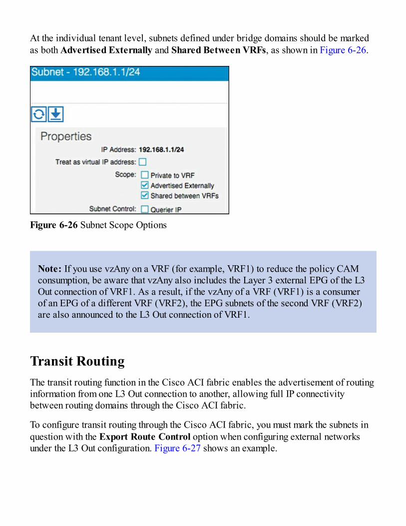
At the individual tenant level, subnets defined under bridge domains should be markedas both Advertised Externally and Shared Between VRFs, as shown in Figure 6-26.
Figure 6-26 Subnet Scope Options
Note: If you use vzAny on a VRF (for example, VRF1) to reduce the policy CAMconsumption, be aware that vzAny also includes the Layer 3 external EPG of the L3Out connection of VRF1. As a result, if the vzAny of a VRF (VRF1) is a consumerof an EPG of a different VRF (VRF2), the EPG subnets of the second VRF (VRF2)are also announced to the L3 Out connection of VRF1.
Transit RoutingThe transit routing function in the Cisco ACI fabric enables the advertisement of routinginformation from one L3 Out connection to another, allowing full IP connectivitybetween routing domains through the Cisco ACI fabric.
To configure transit routing through the Cisco ACI fabric, you must mark the subnets inquestion with the Export Route Control option when configuring external networksunder the L3 Out configuration. Figure 6-27 shows an example.
||||||||||||||||||||
||||||||||||||||||||

Figure 6-27 Export Route Control Operation
In the example in Figure 6-27, the desired outcome is for subnet 60.1.1.0/24 (which hasbeen received from Router 1) to be advertised through the Cisco ACI fabric to Router 2.To achieve this, the 60.1.1.0/24 subnet must be defined on the second L3 Out andmarked as an export route control subnet. This will cause the subnet to be redistributedfrom MP-BGP to the routing protocol in use between the fabric and Router 2.
It may not be feasible or scalable to define all possible subnets individually as exportroute control subnets. It is therefore possible to define an aggregate option that willmark all subnets with export route control. Figure 6-28 shows an example.
Technet24||||||||||||||||||||
||||||||||||||||||||

Figure 6-28 Aggregate Export Option
In the example in Figure 6-28, there are a number of subnets received from Router 1 thatshould be advertised to Router 2. Rather than defining each subnet individually, theadministrator can define the 0.0.0.0/0 subnet and mark it with both export route controland the Aggregate export option. This option instructs the fabric that all transit routesshould be advertised from this L3 Out. Note that the Aggregate export option does notactually configure route aggregation or summarization; it is simply a method to specifyall possible subnets as exported routes. Note also that this option works only when thesubnet is 0.0.0.0/0; the option will not be available when you’re configuring any subnetsother than 0.0.0.0/0.
In some scenarios, you may need to export static routes between L3 Out connections, asshown in Figure 6-29.
||||||||||||||||||||
||||||||||||||||||||

Figure 6-29 Exporting Static Routes
In the example in Figure 6-29, a static route to 60.1.1.0 is configured on the left L3 Out.If you need to advertise the static route through the right L3 Out, the exact subnet must beconfigured and marked with export route control. A 0.0.0.0/0 aggregate export subnetwill not match the static route.
Finally, note that route export control affects only routes that have been advertised to theCisco ACI fabric from outside. It has no effect on subnets that exist on internal bridgedomains.
Route maps are used on the leaf nodes to control the redistribution from BGP to the L3Out routing protocol. For example, in the output in Example 6-1, a route map is used forcontrolling the redistribution between BGP and OSPF.
Example 6-1 Controlling Redistribution with a Route MapClick here to view code image
Leaf-101# show ip ospf vrf tenant-1:vrf-1Routing Process default with ID 6.6.6.6 VRF tenant-1:vrf-1Stateful High Availability enabledSupports only single TOS(TOS0) routesSupports opaque LSATable-map using route-map exp-ctx-2818049-deny-external-tagRedistributing External Routes from
Technet24||||||||||||||||||||
||||||||||||||||||||

static route-map exp-ctx-st-2818049
direct route-map exp-ctx-st-2818049
bgp route-map exp-ctx-proto-2818049
eigrp route-map exp-ctx-proto-2818049
Further analysis of the route map shows that prefix lists are used to specify the routes tobe exported from the fabric, as demonstrated in Example 6-2.
Example 6-2 Using Prefix Lists to Specify Which Routes to ExportClick here to view code image
Leaf-101# show route-map exp-ctx-proto-2818049route-map exp-ctx-proto-2818049, permit, sequence 7801Match clauses:ip address prefix-lists: IPv6-deny-all IPv4-proto16389-2818049-exc-ext-inferred- exportDST Set clauses: tag 4294967295route-map exp-ctx-proto-2818049, permit, sequence 9801Match clauses:ip address prefix-lists: IPv6-deny-all IPv4-proto49160-2818049-agg-ext-inferred- exportDST Set clauses: tag 4294967295
Finally, analysis of the prefix list shows the exact routes that were marked as exportroute control in the L3 Out connection, as demonstrated in Example 6-3.
Example 6-3 Routes Marked as Export RouteClick here to view code image
Leaf-101# show ip prefix-list IPv4-proto16389-2818049-exc-ext-inferred-exportDST ip prefix-list IPv4-proto16389-2818049-exc-ext-inferred-exportDST:
||||||||||||||||||||
||||||||||||||||||||

1 entriesseq 1 permit 70.1.1.0/24
Supported Combinations for Transit RoutingSome limitations exist on the supported transit routing combinations through the fabric.In other words, transit routing is not possible between all the available routingprotocols. For example, at the time of this writing, transit routing is not supportedbetween two connections if one is running EIGRP and the other is running BGP.
The latest matrix showing supported transit routing combinations is available at thefollowing link:
http://www.cisco.com/c/en/us/td/docs/switches/datacenter/aci/apic/sw/kb/b_KB_Transit_Routing.html
Loop Prevention in Transit Routing ScenariosWhen the Cisco ACI fabric advertises routes to an external routing device using OSPFor EIGRP, all advertised routes are tagged with the number 4294967295 by default. Forloop-prevention purposes, the fabric will not accept routes inbound with the4294967295 tag. This may cause issues in some scenarios where tenants and VRFs areconnected together through external routing devices, or in some transit routing scenariossuch as the example shown in Figure 6-30.
Technet24||||||||||||||||||||
||||||||||||||||||||

Figure 6-30 Loop Prevention with Transit Routing
In the example in Figure 6-30, an external route (30.1.0.0/16) is advertised in CiscoACI Tenant 2, which is acting as a transit route. This route is advertised to the firewallthrough the second L3 Out, but with a route tag of 4294967295. When this routeadvertisement reaches Cisco ACI Tenant 1, it is dropped due to the tag.
To avoid this situation, the default route tag value should be changed under the tenantVRF, as shown in Figure 6-31.
Figure 6-31 Changing Route Tags
||||||||||||||||||||
||||||||||||||||||||

WAN IntegrationIn Release 2.0 of the Cisco ACI software, a new option for external Layer 3connectivity is available, known as Layer 3 Ethernet Virtual Private Network overFabric WAN (for more information, see the document “Cisco ACI Fabric and WANIntegration with Cisco Nexus 7000 Series Switches and Cisco ASR Routers WhitePaper” at Cisco.com [http://tinyurl.com/ACIFabNex]).
This option uses a single BGP session from the Cisco ACI spine switches to theexternal WAN device. All tenants are able to share this single connection, whichdramatically reduces the number of tenant L3 Out connections required.
Additional benefits of this configuration are that the controller handles all of the fabric-facing WAN configuration per tenant. Also, when this configuration is used withmultiple fabrics or multiple pods, host routes will be shared with the external networkto facilitate optimal routing of inbound traffic to the correct fabric and resources. Therecommended approach is that all WAN integration routers have neighbor relationshipswith ACI fabrics (spines) at each site.
Figure 6-32 shows Layer 3 EVPN over fabric WAN.
Note that Layer 3 EVPN connectivity differs from regular tenant L3 Out connectivity inthat the physical connections are formed from the spine switches rather than leaf nodes.Layer 3 EVPN requires an L3 Out connection to be configured in the Infra tenant. ThisL3 Out connection will be configured to use BGP and to peer with the external WANdevice. The BGP peer will be configured for WAN connectivity under the BGP peerprofile, as shown in Figure 6-33.
Technet24||||||||||||||||||||
||||||||||||||||||||

Figure 6-32 Layer 3 EVPN over Fabric WAN
Figure 6-33 BGP WAN Connectivity Configuration
||||||||||||||||||||
||||||||||||||||||||

The L3 Out connection must also be configured with a provider label. Each individualtenant will then be configured with a local L3 Out connection configured with aconsumer label, which will match the provider label configured on the Infra L3 Outconnection.
Note: At press time, this capability is only available on three platforms: the CiscoNexus 7000 Series switch with F3 line card, and the ASR 9K and 1K routers.
Design Recommendations for Multitenant External Layer3 ConnectivityIn a small-to-medium-size environment (up to a few hundred tenants) and inenvironments where the external routing devices do not support EVPN connectivity, it isacceptable and recommended to use individual L3 Out connections per tenant. This isanalogous to the use of VRF-lite in traditional environments, where each routedconnection is trunked as a separate VLAN and subinterface on the physical links fromthe leaf nodes to the external device.
In a larger environment, the L3 Out per-tenant approach may not scale to the requiredlevel. For example, the total number of L3 Out connections for a given Cisco ACI fabricis 400 at press time. In that case, the recommended approach is to use Layer 3 EVPNover fabric WAN to achieve multitenant Layer 3 connectivity from the fabric. Thisapproach will provide a greater scale and is also preferred over the shared L3 Outapproach described earlier in this document. Finally, if your organization will beleveraging ACI in multiple fabric or multiple pod topologies for disaster recovery oractive/active scenarios, where path optimization is a concern, Layer 3 EVPN overfabric WAN should be a consideration.
Technet24||||||||||||||||||||
||||||||||||||||||||

Quality of ServiceThe ACI fabric will transport a multitude of applications and data. The applicationsyour data center supports will no doubt have different levels of service assigned tothese applications based on their criticality to the business. Data center fabrics mustprovide secure, predictable, measurable, and sometimes guaranteed services. Achievingthe required Quality of Service (QoS) by effectively managing the priority of yourorganization’s applications on the fabric is important when deploying a successful end-to-end business solution. Thus, QoS is the set of techniques to manage data center fabricresources.
As with normal QoS, QoS within ACI deals with classes and markings to place trafficinto these classes. Each QoS class represents a Class of Service, and is equivalent to“qos-group” in traditional NXOS. Each Class of Service maps to a Queue or set ofQueues in Hardware. Each Class of Service can be configured with various options,including a scheduling policy (Weighted Round Robin or Strict Priority, WRR beingdefault), min buffer (guaranteed buffer), and/or a max buffer (static or dynamic, dynamicbeing default).
These classes are configured at a system level, and are therefore called system classes.At the system level, there are six supported classes, including three user-defined classesand three reserved classes which are not configurable by the user.
User-Defined ClassesAs mentioned above, there is a maximum of three user-defined classes within ACI. Thethree classes are:
Level1 Level2 Level3 (always enabled & equivalent to best-effort class in traditional NXOS)
All of the QoS classes are configured for all ports in the fabric. This includes both thehost-facing ports and the fabric or uplink ports. There is no per-port configuration ofQoS classes in ACI as with some of the other Cisco technologies. Only one of theseuser-defined classes can be set as a strict priority class at any time.
||||||||||||||||||||
||||||||||||||||||||

Reserved ClassesAs mentioned above, there are three reserved classes that are not configurable by theuser:
Insieme Fabric Controller (IFC) Class — All APIC-originated or -destined traffic isclassified into this class. This class has the following characteristics. It is a strictpriority class. When Flowlet prioritization mode is enabled, prioritized packets usethis class.
Control Class (Supervisor Class) — This class has the following characteristics. Itis a strict priority class. All supervisor-generated traffic is classified into this class.All control traffic, such as protocol packets, uses this class.
SPAN Class — All SPAN and ERSPAN traffic is classified into this class. Thisclass has the following characteristics. It is a best effort class. This class uses acongestion algorithm of Deficit Weighted Round Robin (DWRR) and least possibleweight parameters. This class can be starved.
Classification and MarkingWhen Quality of Service is being used in ACI to classify packets, packets are classifiedusing layer 2 Dot1p Policy, layer 3 Differentiated Services Code Point (DSCP) policy,or Contracts. The policies used to configure and apply DSCP and Dot1p are configuredat the EPG level using a “Custom QoS Policy”. In the “Custom QoS Policy” a range ofDSCP or Dot1p values will be used to create a rule and map these values to a DSCPtarget. If both Dot1p and DSCP policy are configured within an EPG, the DSCP policytakes precedence. The order in which one QoS policy takes precedence over another isbased on the following list starting with the highest priority and ending with the lowest:
1. Zone rule2. EPG-based DSCP policy3. EPG-based Dot1p Policy4. EPG-based default qos-grp
A second example of this hierarchy would be if a packet matches both a zone rule with aQoS action and an EPG-based policy. The zone rule action will take presidence. If thereis no QoS policy configured for an EPG, all traffic will fall into the default QoS group(qos-grp).
Technet24||||||||||||||||||||
||||||||||||||||||||

QoS Configuration in ACIOnce you understand classification and marking, configuration of QoS in ACI isstraightforward. Within the APIC GUI, there are three main steps to configure your EPGto use QoS:
1. Configure Global QoS Class parameters — The configuration performed hereallows administrators to set the properties for the individual class.
2. Configure Custom QoS Policy within the EPG (if necessary) — This configurationlets administrators specify what traffic to look for and what to do with that traffic.
3. Assign QoS Class and/or Custom QoS Class (if applicable) to your EPG.
Contracts can also be used to classify and mark traffic between EPGs. For instance,your organization may have the requirement to have traffic marked specifically withDSCP values within the ACI fabric so these markings are seen at egress of the ACIfabric, allowing appropriate treatment on data center edge devices. The high-level stepsto configure QoS marking using contracts are as follows:
1. ACI Global QoS policies should be enabled.2. Create filters — Any TCP/UDP port can be used in the filter for later classification
in the contract subject. The filters that are defined will allow for separate markingand classification of traffic based on traffic type. For example, SSH traffic can beassigned higher priority than other traffic. Two filters would have to be defined, onematching SSH, and one matching all IP traffic.
3. Define a Contract to be provided and consumed.4. Add subjects to the contract.
1. Specify the directionality (bidirectional or one-way) of the subject and filters2. Add filters to the subject3. Assign a QoS class4. Assign a target DSCP
5. Repeat as necessary for additional subjects and filters.
Traffic matching on the filter will now be marked with the specified DSCP value persubject.
||||||||||||||||||||
||||||||||||||||||||

MulticastMany enterprise data center applications require IP multicast support and rely onmulticast packet delivery across Layer 3 boundaries to provide necessary services andfunctions.
Previous versions of the ACI fabric were limited to constraining IPv4 multicast at Layer2 within each bridge domain based on the Internet Group Management Protocol (IGMP)snooping state. Any inter–bridge domain multicast routing, as well as multicast routingin to or out of the Cisco ACI fabric, requires a Protocol-Independent Multicast (PIM)router external to the fabric to perform those functions.
With the introduction of APIC 2.0(1), along with the Cisco Nexus 9300 EX leaf-switchplatforms based on the leaf-and-spine engine (LSE) application-specific integratedcircuit (ASIC), the Cisco ACI fabric itself provides distributed Layer 3 IP multicastrouting between bridge domains, reducing or eliminating the need for external multicastrouters.
The following multicast protocols are now supported with the 2.0(1) release:
PIM any-source multicast (PIM-ASM) PIM source-specific multicast (PIM-SSM) Static rendezvous point (RP), Auto-RP, and bootstrap router (BSR) for RP-to-groupmapping
Note: Bidirectional PIM (PIM-bidir), IPv6 multicast (PIM6 and multicast listenerdiscovery [MLD]), and PIM rendezvous point functions are not supported in theCisco ACI fabric in APIC 2.0(1). In addition, Layer 3 multicast routing is notsupported with fabric extenders or in conjunction with the Multi-Pod function, alsointroduced in APIC 2.0(1).
Native Layer 3 IP multicast forwarding between bridge domains in the Cisco ACI fabricrequires Cisco Nexus 9300 EX platform leaf switches, built with the LSE ASIC. Earlierleaf-switch platforms do not have the hardware capability to perform inter–bridgedomain multicast routing and require an external multicast router to perform thisfunction.
Technet24||||||||||||||||||||
||||||||||||||||||||

Multicast Best-Practice RecommendationsThis section describes recommended best practices for three possible Cisco ACI fabricdeployment scenarios. The scenarios differ in the capabilities of the leaf-switchplatforms (see Figure 6-34):
All leaf switches are first-generation switches that do not use the Cisco Nexus EXplatform. They are based on the application leaf engine (ALE) ASICs and requireexternal multicast routers to perform inter–bridge domain and entry and exitmulticast routing.
All leaf switches are second-generation Cisco Nexus EX platform switches. Theyare based on the LSE ASIC and support native inter–bridge domain Layer 3multicast routing as well as entry and exit multicast routing at the border leaf.
The leaf switches are a hybrid of some Cisco Nexus EX platform leaf switches andsome leaf switches that do not use the EX platform.
Figure 6-34 Three Possible Multicast Deployment Scenarios
Scenario 1: Leaf Switches Not Based on Cisco Nexus EX PlatformThe best-practice recommendation is integration of external multicast routers with theCisco ACI fabric to support inter–bridge domain and entry and exit IP multicast routing,as shown in Figure 6-35.
||||||||||||||||||||
||||||||||||||||||||

Figure 6-35 Scenario 1: External PIM Router
Scenario 2: Leaf Switches Based on Cisco Nexus EX PlatformFor Cisco ACI fabrics in which all leaf switches are based on the EX platform (seeFigure 6-36), the best-practice recommendation is to enable native IP multicast routingin the Cisco ACI fabric. This configuration uses the latest technology generation,simplifies the network design, and simplifies IP multicast routing configuration andmanagement. Documentation outlining how to enable multicast in the ACI fabric can befound in “Cisco ACI and Layer 3 Multicast” at Cisco.com(http://tinyurl.com/ACIL3Multi).
Technet24||||||||||||||||||||
||||||||||||||||||||

Figure 6-36 Scenario 2: Native Layer 3 Multicast
Scenario 3: Hybrid Fabric with Leaf Switches Both Based on and NotBased on Cisco Nexus EX PlatformIn a hybrid environment (see Figure 6-37), in which some of the leaf switches are notbased on the EX platform and others are based on the EX platform, the best-practicerecommendation is to continue to use an external router to perform multicast routing.Although it is technically possible to combine native multicast routing on EX platformleaf switches for some bridge domains with external multicast routing, for other bridgedomains, design, configuration, and management become increasingly complex anderror-prone.
||||||||||||||||||||
||||||||||||||||||||

Figure 6-37 Scenario 3: Hybrid Leaf Capability
Furthermore, when you enable multicast routing in the APIC, you enable it at the tenantVRF level and then, optionally, at the bridge domain level. For example, if you have atenant VRF instance with multiple bridge domains, you can enable Layer 3 multicast onall those bridge domains or only on a subset. In either case, you must first enablemulticast at the VRF level in order to enable multicast routing on one or more bridgedomains within that VRF instance (see Figure 6-38).
Figure 6-38 Layer 2 Versus Layer 3 Multicast for Tenant VRF Instances and BridgeDomains
Technet24||||||||||||||||||||
||||||||||||||||||||

As shown in Figure 6-38, Tenant VRF1 has Layer 3 multicast enabled for the VRFinstance and for all the bridge domains in that VRF instance. Leaf switches can routemulticast traffic between any of those bridge domains, and border leaf switches canroute traffic in to and out of the Cisco ACI fabric for those bridge domains.
Tenant VRF2 has Layer 3 multicast enabled for the VRF instance, but not all the bridgedomains have Layer 3 multicast enabled. Leaf switches can route multicast trafficbetween BD1 and BD2, but not into BD3. BD3 may or may not have Layer 2 multicastenabled (Layer 2 multicast with IGMP snooping in the bridge domain is enabled bydefault but can be disabled). If it does, IP multicast traffic can be constrained within thebridge domain, but it cannot be routed to other bridge domains or in to and out of thefabric.
Tenant VRF3 does not have Layer 3 multicast enabled, but may have Layer 2 multicastenabled for some or all the bridge domains. The leaf switches perform no inter–bridgedomain routing in this case. An external PIM router must provide any inter–bridgedomain multicast routing.
Multicast Configuration OverviewIn this section we examine the minimum configuration needed to support both PIM-ASMand PIM-SSM.
Minimum Multicast Configuration: PIM-ASMThe minimum configuration for basic Layer 3 PIM-ASM requires you to enablemulticast for the VRF instance, add one or more bridge domains on the Interfacesconfiguration subtab, and define a static rendezvous point address in the RendezvousPoints subtab. The PIM rendezvous point must be located outside the Cisco ACI fabric.Verify that the rendezvous point IP address is reachable from inside the fabric.
The industry best practice for rendezvous point configuration is AnycastRP usingMulticast Source Discovery Protocol (MSDP), with static rendezvous point addressconfiguration. The Layer 3 multicast configuration in the Cisco ACI fabric providessupport for specifying a static rendezvous point address for PIM-ASM, as well asdynamic options for disseminating rendezvous point information such as BSR and Auto-RP.
||||||||||||||||||||
||||||||||||||||||||

Minimum Multicast Configuration: PIM-SSMThe minimum configuration for basic Layer 3 PIM-SSM requires you to enablemulticast for the VRF instance, add one or more bridge domains on the Interfacesconfiguration subtab, and enable IGMPv3 processing on those bridge domains (PIM-SSM does not require a rendezvous point).
SummaryThe Cisco ACI solution allows you to use standard Layer 3 technologies to connect toexternal networks. These external networks can be Layer 3 connections to an existingnetwork, WAN routers, firewalls, mainframes, or any other Layer 3 device.
This chapter covered the following topics:
L3 physical connectivity considerations Static and supported routing protocols Access control in and out of the fabric through the use of contracts Multitenant routing considerations WAN integration Quality of Service Multicast best-practice recommendations
No matter what you are connecting to, ACI has the ability to provide reliable and high-performance connectivity to meet simple or complex application and data center needs.
Technet24||||||||||||||||||||
||||||||||||||||||||

How Life Is Different with ACI
In this chapter, you will learn the following:
How Cisco ACI makes network administrators’ lives easier How dashboards simplify network operations How to snapshot and restore configurations How to use the software management functionality in Cisco ACI for firmwareupgrades and downgrades
How to use the topology tools in Cisco ACI in order to obtain valuable information How to leverage the centralized CLI in Cisco ACI How to do some typical verifications such as routing table and MAC table checks
As you probably have figured out already, Cisco Application Centric Infrastructure(ACI) can be used as any other network, if you choose to do so. You could configure itusing the command-line interface, without introducing any automation or integration intoother system hypervisors or Layer 4–Layer 7 network services such as firewalls andapplication delivery controllers.
Actually, many organizations that introduce Cisco ACI start like this, using just a bunchof ACI’s features and extending ACI’s functionality, step by step. Introducing a newtechnology should not force you into a new path, just for the sake of it and deployingCisco ACI certainly does not force you into using features that you do not need.
However, Cisco ACI’s different approach to networking introduces new possibilitiesthat can make the life of network professionals much easier. This chapter describes howCisco ACI can make many of the daily tasks of IT administrators easier.
Technet24||||||||||||||||||||
||||||||||||||||||||

Managing Fabrics versus Managing DevicesThe first noticeable difference between Cisco ACI and a traditional network is thecentralized management approach. A Cisco ACI fabric is still a distributed system fromthe data-plane and control-plane perspectives: Each switch knows what it needs to do,and if something unexpected happens, it does not need to ask the Application PolicyInfrastructure Controller (APIC), as previous chapters have explained.
That is actually one main difference as compared to the first approaches to software-defined networking (SDN) that tried to centralize the control plane. As experience hasproven over and over again, distributed systems scale better and are far more resilientthan centralized ones. Why break something that works really well?
However, the management concept of a network does not need to be distributed, too,and that is one of the weaknesses of network architectures that Cisco ACI does solve.This section describes multiple advantages that network professionals get out of CiscoACI’s centralized management architecture.
Centralized CLICisco ACI does have a NX-OS-like command-line interface (CLI) to offer. Cisco ACI'sCLI is implemented on top of Cisco ACI’s REST API. The graphical user interface(GUI) is also based on the same REST API, as well as ACI’s automation and integrationframeworks, as later chapters in the book will show. As a consequence, the functionalitythat Cisco ACI’s CLI offers is consistent with the rest of the ways of interacting withACI, such as the GUI or other automation tools that leverage its API.
Obviously, some new concepts are introduced in Cisco ACI that do not have an NX-OScounterpart (tenants and external networks, for example). However, for the rest of thecommands, Cisco ACI’s CLI is very similar to what network engineers know from otherCisco Nexus products. Showing the MAC address table at the switches, a list of thevirtual routing and forwarding (VRF) tables, and the state of the interfaces are someactivities that network operators often do on a daily basis.
However, if the network contains a lot of switches, sometimes it can be tricky to knowon which switch to run the command. Where should you start looking for a MACaddress? Where exactly is the routing adjacency being established? With Cisco ACI’scentralized CLI, you can run a certain CLI command on one switch, on a subset ofswitches, or on all of them to be able to quickly find the information you’re searchingfor.
||||||||||||||||||||
||||||||||||||||||||

Have you ever executed a network change that requires having four Secure Shell (SSH)windows open at the same time, and you need to switch from one to the next? WithCisco ACI, this operational burden is greatly reduced, as you have seen throughout thisbook. Not only are show commands centralized, but network administrators can go intoconfig t mode to configure simple or complex ACI policies through the APIC CLI.
Just to mention one example, think of how you would find where a certain IP address isattached to the network. In a traditional network, you would first try to figure out itsMAC address at the default gateway. Then you would try to find that MAC in thedistribution switches, and finally you would track it down to the (hopefully) right accessswitch. By the time you are done, that information might already be stale, because thoseIP and MAC addresses might belong to a virtual machine (VM) that has been moved to adifferent hypervisor.
As opposed to that complex process, you could just issue a single command at the CiscoACI controller, and that would tell you exactly on which port (or ports) a certain IPaddress is connected, as demonstrated in Example 7-1.
Example 7-1 Using Cisco ACI’s Centralized CLI to Find MAC and IP Addresses ofEndpoints Connected to Any Switch in the FabricClick here to view code image
apic# show endpoints ip 192.168.20.11
Dynamic Endpoints:Tenant : Pod2Application : Pod2AEPg : EPG1 End Point MAC IP Address Node Interface Encap----------------- ------------------------ ------ --------------- --------00:50:56:AC:D1:71 192.168.20.11 202 eth102/1/1 vlan-12 Total Dynamic Endpoints: 1Total Static Endpoints: 0apic#
Technet24||||||||||||||||||||
||||||||||||||||||||

Example 7-1 demonstrates the power of a centralized CLI; more examples of usefulcommands are provided throughout this book.
Nevertheless, the overall recommendation is to use the GUI for complex changes,because the GUI offers multiple support tools when configuring policies: immediatefeedback in case the network configuration provokes faults in the system, wizards thatfacilitate common tasks, and contextual help that offers additional information aboutwhat is being configured.
System DashboardDashboards are another manifestation of the centralized management character of CiscoACI. Dashboards are useful not only for non-networking people in order to understandthe overall state of the fabric, but they can be extremely useful for network professionalsas well. Imagine you are a network operator, you come in for your work shift, and youwant to get a sense of how your switches are performing today. Where do you start?Most likely your organization has built some kind of fault-overview system that willshow network devices in green, yellow, or red (“traffic light” monitoring tools) so that aglimpse into that tool will suffice to see whether anything unusual is going on.
This is the main concept of a dashboard—to deliver a quick summary of the state of acomplex system, with the possibility of drilling down if additional details are required.
You could argue that the network itself should actually give this functionality out of thebox. If you think about it, why should you buy yet another tool just to know what yournetwork is doing? Shouldn’t the network be able to tell? Or are networks todayincomplete systems that leave it up to the user to define how they should be managed?
Another problem of the traditional approach is the lack of application centricity. One ofthe main limitations of traditional networking is that application and customerknowledge gets lost. What does it mean that a certain device shows as yellow or evenred in the monitoring system? Is there any impact for any customer? If so, to which one?To which of the applications of that customer? Putting the application and customerknowledge back into the network is not an easy task to do, and Chapter 8, “Moving toApplication-Centric Networking,” will lay out different strategies for doing that.
Furthermore, imagine the situation where not one but two devices go red. On whichproblem should the network operator focus next? Knowing the application and customerimpact of each of the problems would help the person troubleshooting the networkdetermine which one of the two problems is more urgent, and where to focus first.
||||||||||||||||||||
||||||||||||||||||||

This information and much more is what can be rendered available in ACI in an easy-to-consume fashion, without having to acquire additional tools to do so. When you login to ACI, the first page you see is actually the overall system dashboard, and from thereyou can decide what to do next.
For example, Figure 7-1 depicts something similar to the usual traffic-light-basedmonitoring system that network operators are used to working with today, but enrichedwith the concept of tenants, which is discussed in the next section.
Tenant DashboardsThe concept of tenants has already appeared multiple times in this book, and Chapter 9,“Multi-Tenancy,” explains it in depth. For this section, you only need to know that CiscoACI can optionally divide the physical network into different sections, which aremanaged independently from each other. This is what is generally referred to as multi-tenancy. If you are not using multi-tenancy in your system, though, you probably haveconfigured your network objects under the default tenant that comes preconfigured inACI, called “common.”
In any case, if you see in the network dashboard that the health of a tenant is not 100%,you will probably want to gather additional information in order to identify and fix theproblem. Intuitively, most people will double-click the tenant name, and that will takeyou from the overall system dashboard to the tenant page showing the tenant dashboard.Here, you can run multiple verifications and find out more detailed information aboutthe objects that are grouped below this specific tenant.
Technet24||||||||||||||||||||
||||||||||||||||||||

Figure 7-1 Cisco ACI System Dashboard
||||||||||||||||||||
||||||||||||||||||||

Figure 7-2 Tenant Dashboard
As you can see in Figure 7-2, the tenant dashboard gives detailed information about theapplications and the endpoint groups (EPGs) inside of those applications that areimpacted by the problem—or maybe, as in Figure 7-2, the absence of problems for allapplications and EPGs. This is a very intuitive way of locating network problems fromthe top down, starting with the most critical applications in the network and workingdown to the problems impacting them, instead of trying to figure out the impact ofspecific network issues.
Technet24||||||||||||||||||||
||||||||||||||||||||

Health ScoresHealth scores are offered in ACI as a visual summary of the operational state of anyobject. Instead of just three possible states (green, yellow, and red), Cisco ACIcalculates what is called a health score: a number between 0 and 100 that not onlyshows whether a certain object is healthy but also provides an accurate evaluation ofhow close or how far that object is to the state of perfect health. A health score of 100%means that the specific object is operating as it should in every way. On the other side ofthe scale, as you can imagine, a health score of 0% means that that object is completelyinoperative.
Health scores are calculated depending on whether there are active alerts in the systemassociated with a certain object, taking into account the number and severity of thosealerts. How this is calculated is documented in the APIC in the Fabric tab, and someparameters of that calculation can be modified, as Figure 7-3 shows.
Figure 7-3 Modifying Health Score Calculation Parameters
Cisco ACI will take all alerts that refer to a certain object and use them to evaluate itshealth score. As you can imagine, not every alert is treated the same, because more
||||||||||||||||||||
||||||||||||||||||||

severe ones should more greatly impact the health score. You can see the weight withwhich different alert types (critical, major, minor, and warning) are considered in orderto calculate the health score.
Because most people are visual, Cisco ACI associates the health score scale withcolors: the range 0 to 100 is divided in three parts, each associated with a color. Hereare the default settings:
0% to 32%: red
33% to 65%: yellow
66% to 100%: green
These thresholds affect only the color in which health scores are shown in the GUI; theydo not have any other effect in the system. Cisco ACI will not do anything special justbecause a certain object has changed from green to yellow, for example.
Physical and Logical ObjectsThe previous section discussed how Cisco ACI calculates health scores for mostobjects in the system. But what is an object? An object can be anything in Cisco ACI,such as a network segment, a broadcast domain, a switch, an Ethernet port—the listgoes on and on.
As you may have realized, some of the objects in ACI are physical (for example, aswitch and Ethernet port) and others are logical (for example, a network segment andbroadcast domain).
Logical objects are typically groupings of physical objects. For example, an EPG isassociated to a list of ports. Assume that one EPG is configured on four differentphysical ports; if one of those goes down, the health score of the EPG will go downfrom 100% to 75%.
Logical objects are abstractions that greatly simplify network management. If you thinkabout it, the network industry has always used logical object groupings in order tomanage IT systems, but ACI now incorporates new sophisticated ways of groupingobjects. The ultimate object groupings in ACI are tenants and applications, and this iswhat gives Cisco ACI its name. Logical groups and the Cisco ACI object model are thetrue secret behind Cisco ACI’s success.
Health scores are calculated from the bottom up: Failures in the physical objects are
Technet24||||||||||||||||||||
||||||||||||||||||||

weighted and reflected in the logical groups. In the preceding example, a port failurewill reduce the health score of one or more EPGs. This will result in bringing down thehealth score of the application network profile that contains those EPGs, and as aconsequence, the health score of the tenant containing that application network profile.This will be reflected in the overall system dashboard so that the network operator canquickly view in the tenant (the top logical object grouping) any faults that can happen inindividual physical objects.
By default, Cisco ACI dashboards show only objects that do not have a health score of100%. In other words, objects that have an anomaly, even a small one. Most dashboardwidgets contain a sliding bar with which you can specify the objects to be shown. If youmove it to the far right end, all objects will be shown, even those with 100% health. If,on the other hand, you move it to the left, you can set a threshold so that only objectswith a lower health score will be shown.
More importantly, health scores are calculated globally, regardless of whether theservers for a certain application are localized in a single rack or spread all across thedata center. This is the power of application centricity, as opposed to the devicecentricity of legacy networks.
Network PoliciesThe concept of policies is central to Cisco Application Centric Infrastructure. But whatis a policy? This section defines a policy as a sort of configuration template that can beapplied to one or multiple objects of a certain type. For example, if you are familiarwith the way in which ports are configured in many Cisco devices, you might befamiliar with the concept of a port profile, which is a configuration template (or policy)that can be applied to one or multiple ports. If you modify the original port profile, allports that refer to it will inherit that modification: You make one single change and itaffects multiple objects.
Fabric-wide PoliciesCisco ACI takes this concept of a policy or configuration template to a whole newdimension. In fact, virtually all configuration parameters of the network are managed viapolicies, which makes ACI very flexible and easier to operate.
For example, think of Network Time Protocol (NTP) configuration. In traditionalnetworks, you need to log in to every single switch and configure the appropriate NTPservers. If you want to add a new NTP server, you need to log back in again to every
||||||||||||||||||||
||||||||||||||||||||

single switch to make the change. Other than the obvious overhead and inefficient usageof the network administrators’ time, this process is error prone and difficult to audit.How can you be sure that all your switches are compliant with your standards and havethe right NTP servers configured? Again, through logging in to every single switch andverifying.
In ACI, you would configure NTP differently. You would configure an NTP policy once,with the NTP servers that you want every switch to have, as Figure 7-4 shows. Thecontroller will take care of configuring every single switch. If you want to add a newNTP server, you add it once to your fabric-wide policy, regardless of whether you havefour switches in the fabric or 100. If you want to check what the NTP configuration ofyour fabric is, you just need to verify this single fabric-wide NTP policy, period. This isa much more efficient and effective way of configuring this particular feature, but thesame applies to many other global configuration settings—SNMP, Call Home, QoS, oranything else.
Figure 7-4 NTP as an Example of a Single Policy That Applies to Multiple Switches
You will find most fabric-wide network policies in the Fabric Policies section of theFabric tab of the GUI, although some policies might appear in other, more intuitive
Technet24||||||||||||||||||||
||||||||||||||||||||

places. For example, you can find QoS policies in the Access Policies section of theFabric tab.
Comparing the ACI Controller to Traditional Network ManagementSystemsIf you’ve had some experience with network management software, you might have thefollowing question: How can I be sure that the controller deployed the policiescorrectly to the switches? The answer to that question is two-fold: First, the APIC ismuch more tightly coupled to the switches than traditional network management systems.Second, ACI’s declarative model is a much more robust architecture. In the next fewparagraphs we look at these two characteristics of ACI more in detail.
ACI’s controller-based architecture is not to be mistaken with legacy networkmanagement software, which is normally loosely coupled to network devices. That is tosay, there are many factors that can break the integration between the controller (say, atraditional network management tool) and the controlled devices. For example, themanagement software might not support the hardware of the software of a specificdevice, network connectivity might be broken, or you could simply have stored thewrong Simple Network Management Protocol (SNMP) credentials in the managementstation.
In ACI, the controller and the switches are very tightly coupled. Here are some aspectsthat illustrate this integration, but bear in mind this list is by no means exhaustive:
There is a very specific network topology that has been thoroughly tested andvalidated (the APICs attached to leaf switches, and the leaf switches attached tospine switches), where the network connectivity parameters are self-maintained, asyou saw in previous sections (the communication between controller and switcheshappens over the infrastructure IP range). In other words, most likely you could notbreak the connectivity even if you wanted to. Therefore, there is little chance that acontroller cannot reach a leaf or a spine, unless, of course, there are cablingproblems.
ACI hardware and software are specifically designed to be controlled by an APIC.That is, all features without any exception are configurable via the controller. Forgetabout interoperability matrixes or hardware compatibility lists that you might knowfrom legacy network management systems.
Communication between the controller and switches is secured over Transport LayerSecurity (TLS), and no credential database in the controller needs to be maintained.
||||||||||||||||||||
||||||||||||||||||||

Coupling between the devices and controller happens without user interaction atfabric discovery time. Thus, it is virtually impossible for this coupling to be brokendue to misconfiguration.
So, an event in which a policy is not properly deployed to the switches is highlyunlikely. If you are a CLI person and have ever evaluated network managementsoftware, you’ve probably found yourself investigating in the CLI what the heck thatstrange software did when you clicked something, or whether the intended changes wereactually deployed to the switches. I can assure you that with ACI, you will find soonenough that in most cases this is a futile task, because every single policy you define inthe controller GUI (or over the controller REST API, or over the CLI) is reliably andconsistently deployed across the network on all switches that belong to the fabric.
A second big difference when comparing legacy network management systems (NMSs)with Cisco ACI is that ACI uses a declarative model, as opposed to an imperativemodel. What does this mean? The ACI controller will not send configuration commandsto the switches, but just a “description” (a declaration) of what those switches shouldbe doing. The switches will then answer with a positive or a negative answer,depending on whether or not they can fulfill that desire (if they have hardwareresources, if they support that functionality, and so on).
If you compare that to legacy NMSs, you’ll find they typically function following animperative model: They need to understand all the capabilities of the underlying devicesas well as send the exact commands the managed switches understand. Any softwareupgrade that brings a syntax change to those commands will break that integration.
In order to better understand the importance of this concept, you can think of anothertype of controlling system that manages complex devices: an airport control tower. If thetower tried to tell every pilot exactly what they needed to do in order to land their planein an “imperative” fashion (press this button, pull that lever, turn that switch, and so on),there would be two consequences: The system would not scale, and it would be veryfragile (what if the pilot cannot find the button they need to press?). However, if thetower limits itself to giving “declarative” instructions to the pilot (such as “you are thenext one to land on Runway 2”), trusting that the pilot knows how to fly their plane, thenthat system will be much more scalable and robust.
This discussion might appear to be too philosophical, but it is one of the core reasonswhy Cisco ACI is so stable, even when dealing with huge networks and differentdevices, where classical network management approaches tend to collapse.
Technet24||||||||||||||||||||
||||||||||||||||||||

Troubleshooting the Deployment of Global PoliciesNote that earlier we said “in most cases,” because in our universe there are very fewrules without exceptions. Theoretically, there might be some extremely unlikelysituations in which policies are not correctly applied to the switches. Therefore, weneed a way of verifying whether policies have been applied to the switches, no matterhow unlikely this situation might be.
This is one of the use cases for the ACI device-centric CLI. As previously stated, thereare two ways to access it: connecting directly to either the in-band or out-of-bandmanagement IP address of the switch, and connecting via the APIC controller. Comingback to the NTP example, the only task you need to do is to connect to a device over itsCLI and issue the command show ntp peer-status, for example. It’s as easy as that.Alternatively, you can even run that command from the controller on all switches in thenetwork, so that you don't need to check switch after switch. Chapter 12,“Troubleshooting and Monitoring,” includes additional details about multiple ways touse Cisco ACI’s CLI.
Configuring Multiple Ports at the Same TimeMany network administrators are familiar with port profiles, a concept of NX-OS andIOS that allows you to configure multiple ports in a switch at the same time. Youprobably noticed the critical phrase in the previous sentence: “in a switch.” BecauseCisco ACI is a fabric-centric system, rather than a device-centric system, is it possibleto define port ranges that apply to multiple switches?
If you read the previous chapters in this book, you already know the answer—yes,absolutely. This section will not dwell on the details of access policies because theyhave been explained elsewhere in this book. Suffice it to say that through the proper useof ACI access policies, you can solve very elegantly the following tasks:
If you have standards in your data center such as “the first 20 ports of every switchin every rack are used for server management purposes,” you could configure those20 ports in every single switch with a single interface policy covering ports 1through 20 that is applied to all your ACI leaf switches.
If you configure both switches in a rack symmetrically (if a server connects to port15 in switch A, it will connect to port 15 in switch B as well), you can use a singleinterface profile that applies to both leaf switches A and B.
If you want to manage each switch individually to have maximum flexibility, you canstill do so by having interface profiles that apply to single switches.
||||||||||||||||||||
||||||||||||||||||||

And of course, you can use a combination of these three possibilities: configuring someport ranges over all the switches in the fabric, other ports over a subset of the switches(such as the two switches inside of a certain rack), and the rest of the ports individuallyin each switch.
Maintaining the NetworkYou can look at ACI as a network that brings all the required maintenance tools alongwith it. If you think about it, a network is much more than a bunch of switches androuters connected to each other. You need network management tools that help you tomake sure those routers and switches are working as they should. And guess what?Those tools are not included with traditional networks—you need to buy themseparately, and the integration between the tool and the devices is on you.
Cisco ACI is changing the game rules: It brings everything you need in order to operatethe network. The next sections introduce some of the tools, other than packetforwarding, that are a part of Cisco ACI.
Fault ManagementHow are faults managed in a traditional switch? Simple answer: They’re not. Syslogmessages are generated, SNMP traps are sent out, but no fault management conceptexists where the operator can acknowledge faults or where faulty states are tracked andcleared when they disappear. At best, the fault management is very rudimentary, whichis what forces organization(s) to buy expensive monitoring tools that include faultmanagement as part of their network operations.
Faults Across the NetworkCisco has built many fault management functions natively into Cisco ACI. For example,a system-wide fault view in the System tab, as displayed in Figure 7-5, can quicklyshow a summary of all the issues happening at a current state in the network.
Having this centralized fault view is extremely useful, and it is something that legacynetworks cannot offer without the help of external tools. Ideally, you should have zerofaults in your ACI fabric, so any time you see a fault popping up in this panel, it is anindication that some action needs to be taken.
Technet24||||||||||||||||||||
||||||||||||||||||||

As a good practice, it is recommended that you verify in this section of the GUI whetheradditional faults have been generated after executing network configuration changes.
Faults are grouped into categories so that the operator can easily browse over theproblems that are being seen. For example, the last fault in Figure 7-5 indicates thatthresholds have been exceeded. There are exactly two occurrences. Instead of showingtwo different faults, this view aggregates identical faults into a single line. If youdouble-click this line, you would see the two individual faults that make up that tablerow, as Figure 7-6 shows.
Figure 7-5 Centralized View for Fabric-wide Fault Management
||||||||||||||||||||
||||||||||||||||||||

Figure 7-6 Showing Individual Faults
Aggregating two faults into a single line might not sound like a great achievement, butthis hierarchy offers a consolidated view of the state of the network without too muchnoise. Coming back to Figure 7-5, a single screen of information has aggregated morethan 50 faults (if you add up the individual faults that make up each line).
When the details of a single fault are shown, rich information can be displayed to theuser, such as recommended actions to clear the fault or more descriptive text thatexplains further details about the problem. For example, Figure 7-7 shows one exampleof a window with detailed information about the packet drop problems mentionedpreviously.
Technet24||||||||||||||||||||
||||||||||||||||||||

Figure 7-7 Fault Detail Example
One of the fields displayed is Severity. Faults in Cisco ACI can have one of thefollowing severity levels:
Critical Major Minor Warning Info
Critical faults indicate severe network problems that should be investigatedimmediately. Major faults are problems that impact the correct function of the networkand therefore should be looked into as soon as possible. Minor faults representproblems that typically do not impair the network, but represent a certain risk for thesystem integrity. Warnings have no negative impact to the network service, but theyshould be diagnosed before they degenerate in higher-severity issues. Finally,informational messages do not represent any risk to network operation.
||||||||||||||||||||
||||||||||||||||||||

Fault LifecycleFaults follow a predetermined lifecycle during which they can optionally beacknowledged by operators. Faults go through the following phases:
Soaking: The fault has been identified, but in order to avoid sharing faults fortransient conditions, the system waits an interval of time before raising it.
Soaking-Clearing: This state happens if the fault gets cleared while it is in thesoaking state.
Raised: If the fault persists after soaking, it enters the raised state.
Raised-Clearing: This state happens if the fault gets cleared while it is in the raisedstate.
Retaining: After either Soaking-Clearing or Raised-Clearing, a clearing intervalstarts. If after that interval the fault is still inactive, it goes into the Retaining state.After a retaining interval, the fault would be deleted.
If a fault is acknowledged by a user, it gets deleted.
Here are the default values for the intervals associated with fault lifecycle management:
Soaking interval: From 0 to 3600 seconds. The default is 120 seconds.
Clearing interval: From 0 to 3600 seconds. The default is 120 seconds.
Retaining interval: From 0 to 31,536,000 seconds (one year). The default is 3600(one hour).
These timers can be verified and adjusted under the Fabric tab in APIC, as Figure 7-8shows.
Immediate Fault Reporting for Change ValidationAn interesting use of faults is the immediate feedback of whether or not configurationchanges trigger any faulty conditions in the system. This is one reason to use the GUI fornetwork changes, because you can see right away whether your change has successfullygone through the system or if it has triggered any faults.
To that purpose, in most configuration sections of the APIC, you can see a summary ofthe faults related to the objects you are configuring. Figure 7-9, for example, indicatesthat a minor fault has occurred. The four icons represent the four possible faultseverities (critical, major, minor, and warning), and the number is the object’s health
Technet24||||||||||||||||||||
||||||||||||||||||||

score.
Note that this fault summary reflects just the state of the object being configured.Therefore, if somebody else is wreaking havoc on a different object in ACI, you willnot see it reflected in the object you are working on (unless some dependencies existbetween both objects, of course).
Figure 7-8 Fault Lifecycle Management Configurable Parameters
If a network engineer is in the middle of some configuration and this kind of notificationpops up, it is a hint that the deployed configuration is either incorrect or incomplete.Figure 7-9 shows this immediate fault indication, displaying the existence of majorfaults for the currently selected object in the GUI (notice the four icons at the left of thehealth score, denoting the existence of one major fault).
This is a great help in order to identify problems in the middle of a complex action.Compare this with the approach in traditional networks—after pasting a big chunk ofCLI commands into an SSH session, you find that several alerts are thrown back at you,without any possibility of seeing which one of the commands actually triggered theproblem.
||||||||||||||||||||
||||||||||||||||||||

Configuration ManagementConfiguration management is one of the major disciplines of operating a network. In astatic network, you would not need configuration management, because the configurationof every device would always look exactly the same. Real life, however, looksdifferent. For example, think about network changes—sooner or later you will need tomodify the network configuration to accommodate new applications or scale existingones. You need to evaluate the potential impact of those changes, just in case they gowrong. Although most will not, some of those changes will inevitably cause an outage.You need to minimize application impact and be able to roll back to a validconfiguration as soon as possible. These are all examples of configuration managementtasks.
Figure 7-9 Immediate Fault Reporting in the EPG Dashboard
The next few sections discuss how ACI alleviates the burden traditionally associatedwith configuration management of legacy networks.
Technet24||||||||||||||||||||
||||||||||||||||||||

Evaluating Change ImpactHave you ever found yourself, before you press Enter after typing a command into aCLI-driven network, mentally going over all the dependencies and implications youraction might have? Have you ever overlooked one of them, and pressing that Enter keyresults in undesired implications? Most network administrators have been in thatsituation, and that is because evaluating the impact of network changes is not an easything to do.
Cisco ACI introduces certain tools for making that evaluation easier. One of these toolsis the Policy Usage tool, which can inform you about dependencies that might not beapparent, before a change is pushed to the system.
Figure 7-10 shows an example of the Policy Usage information—in this case describingthe potential impact of a change to a Link Layer Discovery Protocol (LLDP) interfacepolicy. Imagine that you feel the urge to modify this specific default policy for LLDP,and you are wondering whether that change could have any impact. By clicking thePolicy Usage button on the LLDP policy, you can see, for example, how many virtualmachines could be impacted if you deploy the wrong default LLDP policy. Having thiskind of visibility might be very useful in order to prevent accidental changes within abig network impact.
||||||||||||||||||||
||||||||||||||||||||

Figure 7-10 Evaluating Change Impact with the Policy Usage Tool
Configuration Zones: Running Changes GraduallySo we have a single system. Does that mean any network administrator can bring itdown with a single wrong policy that is deployed to all switches? Actually, yes, butthat’s the case as well with traditional networks, where, for example, the wrongSpanning Tree or VTP Pruning setting one switch can bring down the whole network.
However, Cisco ACI has a mechanism to partition the network so that system-widechanges can be deployed gradually throughout the system. This offers networkadministrators much more granular control when they are introducing critical changesinto the system.
Cisco ACI is based on policies, as other chapters in this book have already discussed.You can potentially have a certain policy to which many objects refer. Traditionalnetworks also have a concept of policies (for example, port profiles in NX-OS), butthey are limited to individual switches. In ACI, you have network-wide policies.
Is this a bad thing? Absolutely not. It means you can change network behavior veryeasily, which is an important attribute of ACI. But this also means you can introducesevere problems if you are not careful. To control the impact of modifying network-wide policies, Cisco ACI introduces the concept of configuration zones. You can thinkof these zones as a way to execute network changes in a gradual fashion. Even if thepolicy you are modifying is network-wide, it will be changed only in one part of thenetwork—that is, in one configuration zone. When you are satisfied with the change, andit works as expected, you can proceed with the rest of the configuration zones.
You can define configuration zones in the System panel, and you assign leaf switches toeach configuration zone (remember that in Cisco ACI, most policies are deployed inleaf switches). Once you have done that, you can enable or disable the deployment ofconfiguration changes for any given configuration zone. If deployment mode is disabled,policy modifications will not be propagated for that given zone, so no changes will beperformed on the corresponding switches.
If any change has been scheduled but not yet deployed, you will be able to see it, alongwith all pending changes, as Figure 7-11 shows. A network administrator can deploythese changes manually, once there is certainty that they entail no risk.
Technet24||||||||||||||||||||
||||||||||||||||||||

Figure 7-11 Config Zone with Deployment Mode Disabled and Pending Changes
An interesting use case is the combination of configuration zones and stretched fabricdesigns (with or without Multi-Pod technology), where each configuration zone mightbe mapped to one location. As you might remember from previous chapters, a stretchedfabric design is one where your ACI switches are deployed across multiple physicallocations. Multi-Pod is a design variant where you connect the spines in differentlocations to each other over an IP network, instead of direct spine-to-leaf connections,as is the case with stretched designs.
However, chances are that these physical locations exist in the first place in order toachieve higher resiliency and availability levels. So you might argue that creating asingle big management domain, where human error can bring down everything at thesame time, is not something necessarily desirable. An option would be deploying oneindividual ACI fabric in each location, but that would increase the cost and themanagement overhead. Alternatively, you could have the best of both worlds by havingone single ACI fabric and shaping configuration zones to match the physical locationsthat Cisco ACI is stretched upon, to reduce the impact of human error. Or you couldhave a small section of your network configured as a test area with deployment modeenabled, and the production area would have deployment mode disabled. This way,
||||||||||||||||||||
||||||||||||||||||||

network changes would always be run immediately in the test part of your network, butshould be manually deployed in production.
This simple feature of configuration zones allows for having at the same time bothcentralized configuration management and multiple deployment areas, thus greatlyreducing the risk of change deployment
Centralized Change DescriptionHave you ever had a network change that involves multiple devices at the same time—for example, deploying a virtual extensible LAN (VXLAN) over many leaf switches atthe same time, or modifying dynamic routing protocol redistribution over multiple edgedevices? Typically, you would document in the appropriate change request all stepsrequired to run the change in each individual device, as well as all the actions to rollback the change, again for each individual device.
As a consequence, anybody who wants to deploy the change needs to copy yourdocumented actions and paste them, one at a time, in every involved device. Thismanual process dramatically increases the chance for misconfigurations (for example,the operator copies the right configuration chunk but pastes it into the wrong device).
Cisco ACI’s centralized architecture fixes this problem naturally: only oneconfiguration for any change, and only one configuration for any rollback. Also, youhave one single point of management that is based on a modern REST API, whichreduces dramatically the chances for any configuration errors.
You could even document your changes in group-based REST clients so that anyoperator who wants to run your change only needs to send that single request forexecuting the change, thus eliminating the possibility of copy-and-paste errors.
Atomicity of Network ChangesEven though we now have a single point of management, a single configuration to send,and have eliminated the chance for manual mistakes when copying and pasting in a CLI,you could still introduce a mistake in the change definition. This brings into play a veryimportant concept of Cisco ACI—its atomicity.
Imagine you have a very complex change, possibly involving creating multiple VRFs,subnets, and packet filters across many switches. But you made a mistake when writingthe required configuration, and as a consequence, part of the change is syntactically orsemantically wrong (for example, you could be trying to configure the IP address
Technet24||||||||||||||||||||
||||||||||||||||||||

10.20.30.357 on an interface, which will obviously generate an error).
In a traditional CLI-based network, parts of your change would be successfullyimplemented, and those parts that aren’t correct would not be implemented. This resultsin a partially incorrect configuration, which has neither the new state nor the old one.What’s more, rolling back this partial change can be particularly complex because youneed to check which configuration items have been deployed and which ones have not.
If you have ever pasted a big chunk of configuration into an SSH session, you know thefeeling: praying for all the lines to be correct as they are taken by the CLI. Otherwise,rolling back individual lines might be challenging.
In ACI, when you execute a configuration change—either through the GUI, with the CLI,or from an external orchestrator—it will be validated before being implemented, andeither it will be completely deployed or it will not be deployed at all. In other words,Cisco ACI’s API REST calls are atomically executed. And remember that every changein ACI goes through the API, including the CLI and the GUI. For example, if you sendhundreds of lines of JSON code, but a minuscule error is buried somewhere in thoselines, you do not need to worry—your change will be completely rejected, so there’s noneed to roll back anything.
This atomicity has very important consequences and greatly simplifies deployment ofcomplex changes, on top of the architectural benefits of the single point of managementthat Cisco ACI offers.
Configuration SnapshotsNow suppose our configuration change has gone through, and it has been deployed onmultiple zones; however, some hours later, customers report problems. Unfortunately, norollback action was documented, and after troubleshooting, we decide that the bestpossible action is to roll back that change.
Cisco ACI offers the possibility of centralized configuration snapshots and rollbackoperations. You can export the complete network configuration in a single file to anexternal server, and you can import a configuration file to restore the network to aprevious state. Compare that to the manual process of rolling back each switchindividually. Even if you’re using network management tools that support configurationsaving and rollback, you would need to schedule as many rollback operations asswitches you have in the network.
Cisco ACI goes one step further and does not even require that you export these
||||||||||||||||||||
||||||||||||||||||||

configuration snapshots to an external server. You can store them locally in thecontroller nodes, which greatly simplifies the operation of taking the snapshot, thuseliminating interference of network problems or temporary outages of the externalconfiguration server. All that’s required is one single click or REST API call in order tosnapshot the configuration, and one single click or REST API call in order to revert theactive configuration to a snapshot—and that’s network-wide.
The configuration management engine offers you the possibility to compare multiplesnapshots with each other, as Figure 7-12 illustrates. In this case, the XML code beingshown indicates that a new tenant has been created. Note the button Undo thesechanges, which allows you to roll back the change immediately.
Figure 7-12 Comparing Fabric-Wide Configuration Snapshots
What if you don’t want to snapshot all of the configuration but only a part of it? You canrun configuration snapshots of specific objects, or of specific tenants, and restore themas easily. Considering the previous example, you might want to restore the snapshottaken for the specific tenant a few hours ago, without affecting other changes that havebeen introduced for other tenants in the meantime.
Technet24||||||||||||||||||||
||||||||||||||||||||

This is the scenario illustrated by Figure 7-13, where only snapshots for one specifictenant have been taken (note the "for:" text box at the top of the figure).
Is this important? It’s critical, because some organizations purposely reduce the speedat which they deploy network changes so that changes can be rolled back one at a time.For example, a certain change for a specific customer could be rejected, becauseanother change is being run in the same maintenance window. This organization isreducing its agility when coping with changes, because of its inability to properlyperform configuration management when changes are parallelized.
And moreover, that organization is increasing the space between changes, and thereforechanges are bigger, more complex, and entail more risk. Cisco ACI’s embeddedconfiguration management can help an organization to increase its agility, and at thesame time decrease configuration change risks.
Network Audit TrailsHave you ever faced a problem where the cause was an undocumented configurationmistake? In this case, being able to inspect the network for changes is of paramountimportance. Configuration change accounting tools that leverage protocols such asTACACS+ are an integral part of most critical networks.
||||||||||||||||||||
||||||||||||||||||||

Figure 7-13 Tenant-Specific Snapshots
Although Cisco ACI supports TACACS+ integration for authentication andauthorization, it does not need external network auditing tools because it incorporatesthis functionality natively in the APIC controller. You can certainly export networkchanges to centralized accounting tools if you wish, but if you’re wanting to find outabout changes in ACI, the GUI or the API offer all you need.
You have multiple ways you can access these audit trail logs. First of all, in the Fabricsection of the GUI you can find all changes performed to the system across all tenantsand objects. If you don’t know what you are looking for, this is the place to start. Figure7-14 shows a screenshot of the audit log for the whole fabric.
However, you might have some context information that filters the logs you want tosearch. For example, if you are troubleshooting a problem related to a certain tenant,you might want to start looking for changes that have been made for that tenant. To thatpurpose, you can access these tenant-specific audit trail logs from each tenant. AsChapter 9 explains in detail, you can even make this audit trail information available toapplication owners by granting them access to the tenant so that they can see networkactions that could potentially impact their applications, thus greatly enhancing their
Technet24||||||||||||||||||||
||||||||||||||||||||

visibility, as Figure 7-15 describes.
But this audit trail is not just network-wide or tenant-wide. Besides tenants, many otherobjects have a history tab where you can search for changes performed for a specificobject. Or you can even let Cisco ACI show you the relevant audit logs for a specificissue in the Troubleshooting Wizard, which makes configuration accounting extremelyeasy to use. For more details about the Troubleshooting Wizard, refer to Chapter 12,where it is discussed at depth.
Figure 7-14 Network-wide Audit Trail
||||||||||||||||||||
||||||||||||||||||||

Figure 7-15 Tenant-Specific Audit Log
Again, embedded change accounting and audit logs comprise an extremely powerfulnetwork management function of Cisco ACI that can greatly help you pinpoint whatchanges have taken place in any environment. This is useful when troubleshootingproblems, because experience shows that most problems originate from incorrectnetwork changes.
Upgrading the SoftwareSoftware runs in every switch in every network. Every piece of software has features,and along with those features comes software caveats and security vulnerabilities. It isnot a matter of whether the software versions you are using have bugs or security holes.They have them—you can be sure about it. Instead, it is a matter of when you hit one ofthem, how easy and efficient is it to upgrade the software to a new level that fixes theproblem.
There are other not-so-dramatic reasons why you would want to upgrade the software,such as to get new functionality or support for new hardware. In any case, it is a healthy
Technet24||||||||||||||||||||
||||||||||||||||||||

practice to upgrade the software running on your switches on a regular basis. Whetherthe time interval between upgrades should be one month or two years is open to debate,but most organizations upgrade at least once a year, if not more often.
However, not everybody is doing so. The reason is that network software upgradeshave traditionally been a pain in the neck. This process can involve selecting the rightimage on the right switch or router, copying over the image to the device, configuring thedevice so that it takes the image in the next reload, rebooting the device, and checkingthat the new software has loaded accordingly—and that’s for each individual switch orrouter in your network. Most importantly, you want to avoid any service disruptionduring software upgrades. If you have a couple dozen switches in your data center, nowonder your organization might be reluctant to embark on software upgrade tasks.
Cisco ACI has embedded software management tools in the controller that alleviatemost of the challenges just described. First and foremost, the controller can assume thefunctionality of a software repository, from which you can effortlessly orchestratesoftware upgrades and downgrades.
You only need to load two images to the software repository for a software upgrade:one for the controller and one for the switches. The controller images are the same forall controller generations and sizes (at the time of this writing, four controller modelsexist—M1, M2, L1, and L2—and all of them share the same image). Similarly, there isa single switch image for all Nexus 9000 ACI switches, regardless of whether they areleaf or spine switches and on which hardware generation they are based. Two imagesare needed—no more, no less.
The software upgrade (or downgrade) is a three-step process:
Step 1. Upload both software images (for the controller and for the switches).
Step 2. Upgrade the controller cluster.
Step 3. Upgrade the switches.
The first thing you want to do is to upload the images for the new version to ACI’sfirmware repository. After you have the images in the firmware repository, the next stepis upgrading the APIC controller so that it recognizes the switches with the newsoftware when they come up. Remember that in Cisco ACI, the controller is not in thedata plane, so this upgrade is does not have any impact on production traffic. Allcontroller nodes will be upgraded when you initiate the controller upgrade, as Figure 7-16 illustrates, one APIC node after the other. After some minutes of unattendedactivities, your controller cluster will be running on the new software.
||||||||||||||||||||
||||||||||||||||||||

Figure 7-16 Controller Firmware Upgrade
After you verify that all APIC nodes have been correctly upgraded, you can proceedwith the second phase—upgrading the switches. You could certainly do it the same wayas with the controller, and upgrade all in one go (in parallel or sequentially). However,chances are that you want to do this upgrade in stages: First upgrade one switch, seewhether it works, then a couple of more, and then eventually all the rest.
Most customers divide the upgrade into multiple stages, depending on the criticality ofthe network, but you could take the following approach as a good compromise:
1. Upgrade the even spine switches.2. Upgrade the odd spine switches.
3. Upgrade the even leaf switches.4. Upgrade the odd leaf switches.
For example, Figure 7-17 shows a use case where switches have been divided in fourgroups: leaf and spine switches, even and odd. The network admin has chosen toupgrade each group manually and independently of the others. Other possibilities might
Technet24||||||||||||||||||||
||||||||||||||||||||

be automated upgrades in maintenance windows defined in schedulers.
Figure 7-17 Manual Firmware Upgrade of a Subset of Switches
Upgrading the spines does not have any impact for applications, as long as there is atleast one spine up. Leaf switches will redirect traffic to the remaining spine or spines,and applications will not notice any downtime. Similarly, upgrading the leaf switchesdoes not have any application impact, as long as the servers are dual-homed to twoindividual switches, as is normally the case in most environments. That is whyseparating leaf and spine switches in odd and even groups might make sense in manydesigns.
Obviously, in big environments, you’ll probably want to segment this process evenmore. At press time, Cisco ACI supports up to 200 leaf switches, and you probably donot want to upgrade half of them simultaneously, so you would reduce the size of thegroups of switches that are upgraded at a time. These are called maintenance groups inACI, and you can handle them separately. For example, you could manually upgradesome of them, and when you are sure about the software upgrade, let the system upgradethe other maintenance groups in scheduled maintenance windows.
In case you decide to postpone the software upgrade to a later time, you can use either
||||||||||||||||||||
||||||||||||||||||||

one-time triggers or recurring triggers. You would use recurring triggers if you havepredefined maintenance windows (say, once a month) when you can reboot yournetwork. In either case, you have the following options that allow you to further tunehow the upgrade process will be performed, as Figure 7-18 shows:
When the upgrade process should be started How many nodes are allowed to be upgraded concurrently
Figure 7-18 Always Configure a Maximum Running Time When Using Triggers
A very important remark here: Be sure you always configure a maximum running time.Otherwise, you could find yourself with unexpected behaviors, such as a trigger thatinitiates a firmware upgrade days or even weeks after it has been defined. If the triggeris active, and its maximum running time is unlimited, every change in the targetfirmware policy of a maintenance group using that trigger will immediately unleash thefirmware upgrade.
Note that when you’re upgrading the network in phases, a question arises concerninghow long you should have a network running with mixed firmware versions in theswitches and/or the controllers. You need to consider that having different firmware
Technet24||||||||||||||||||||
||||||||||||||||||||

versions poses a risk, because you might run into a combination of different versionsand features that have not been thoroughly tested by Cisco.
The core of the issue involves reducing two risks at the same time:
On one hand, you want to reduce the risk of software problems and device downtimeby rolling out new software to switches and controllers in chunks of devices, not allat the same time.
On the other hand, you want to reduce the risk of running a combination of multiplesoftware versions in the same ACI fabric for a long time.
Cisco’s recommendation is therefore to run software upgrades in phases to minimizeoutages and to verify that the new software does not bring any major bugs that impactyour operation, but to complete the software upgrade in the whole fabric sooner ratherthan later, ideally within a few hours.
Breaking the Shackles of IP DesignTraditional networks are slaves of the underlying IP design. This means that networkadministrators for years have designed their security and network policies based on theborder between IP segments on networks.
Access Control Lists Without IP AddressesAs other chapters in this book have already described, security in Cisco ACI is basedon the concept of contracts, which can be considered a way to define communicationrules between multiple zones or EPGs. Therefore, contract definitions do not includeany IP addresses but rather the UDP or TCP ports over which two or more zones cancommunicate with each other (or the IP protocol or the Ethertype).
As a consequence, network administrators defining a security policy do not need to beconcerned with IP addresses. When contracts are consumed or provided by a certainEPG, the IP addresses of the endpoints in that EPG will be used to configure the securitypolicy.
This fact has very important implications: for example, the network administrator coulddefine the contracts for a certain application, and the same contracts (or multiple copiesfrom the same contract) could be used for different application instances, such asdevelopment, staging, and production environments. Even if the endpoints for each
||||||||||||||||||||
||||||||||||||||||||

application instance have different IP addresses, the contracts can stay the same.
QoS Rules Without IP AddressesAs you have already seen, contracts are a way of define which security zones can speakto each other, without having to type a single IP address. Security is not the onlyattribute defined by contracts, however—the quality of service (QoS) level can bespecified too, in order to indicate how the traffic controlled by the contract should beprioritized by Cisco ACI.
As with the security policies, the network administrator can now define policies(contracts) that can be reused across many applications or application instances,regardless of whether or not the endpoints providing those applications have the sameIP addresses.
QoS Rules Without TCP or UDP PortsBut there is more to it: What if no policy is required to prioritize certain traffic? Youmight think this is not possible, because somebody needs to tell the network whichtraffic is sensitive to latency and which one is sensitive to bandwidth. But what if thenetwork could discern the two traffic categories from each other?
This is where dynamic packet prioritization comes into play, a technology that at presstime was only available in Cisco ACI. For example, for a long time, networkadministrators needed to know on which ports certain latency-sensitive traffic runs,such as VoIP control packets. With this information, QoS rules were configured toprioritize traffic on this port over other packets. However, with dynamic packetprioritization, this is not required anymore: The network admin can leave to the networkitself the job of deciding which packets should be prioritized over which other packets,in order to maximize application throughput for both bandwidth-intensive and latency-sensitive traffic types.
And the best thing about advanced QoS in Cisco ACI is the considerable ease withwhich it can be configured. For example, dynamic packet prioritization can be enabledwith a single click across the fabric, as Figure 7-19 illustrates.
Technet24||||||||||||||||||||
||||||||||||||||||||

Figure 7-19 Enabling Dynamic Packet Prioritization
Physical Network TopologyMany chapters of this book describe policies and other logical objects that are anintegral part of Cisco ACI. However, network operators will most likely want to have alook now and then at the physical objects in Cisco ACI, such as network switches andports. As in any other network, switches are interconnected within a certain topology,servers are connected to switches, and Cisco Fabric Extenders might be used in order toextend the reach of ACI leaf switches.
ACI as a Clos Fabric and Design ImplicationsAs you know by now, Cisco ACI is a Clos fabric—in other words, a spine-and-leafarchitecture. This architecture is by no means something specific to ACI, and it isimplemented by many other network technologies from both Cisco and the networkindustry overall, such as FabricPath or VXLAN, to name just two.
However, some issues specific to Cisco ACI might influence the way in which
||||||||||||||||||||
||||||||||||||||||||

administrators deal with network problems that differs from how they did so in the past,as the following sections discuss.
Connecting Endpoints to Leaf SwitchesNothing can be connected to ACI spines other than ACI leaf switches (multipod designsand WAN router integration in ACI being two notable exceptions). This is not arecommendation, but a strict requirement. However, for network administrators used tolegacy distribution/access designs, this might come as a surprise, because many of thesedesigns used to have critical devices such as firewalls, load balancers, and uplinks tothe network core connected directly to distribution switches.
In Cisco ACI, you cannot do this, so you would probably want to deploy dedicated leafswitches with higher-bandwidth ports in order to connect these devices. At press time,the Nexus 9332PQ is an example of this kind of leaf switch, offering 40Gbps portswhere external devices can be attached. The Cisco Nexus 9000 EX switches introducedsupport for 25Gbps server-facing ports at scale with 100Gbps uplinks.
Scaling an ACI Fabric Means Adding More Leaf SwitchesBut why does ACI have the aforementioned restriction? In other technologies such asFabricPath and VXLAN, you can certainly attach external systems to the spines.However, you need to bear in mind that the moment you do so, you are running twofunctions simultaneously on the same device: the spine function and the leaf function.
On one hand, this gives you more flexibility, but it breaks many of the design principlesof spine/leaf designs. One of these principles is scalability, because in legacy networks,scalability is essentially a scale-up problem at the distribution layer, whereas Closfabrics transform scalability into a scale-out issue at the leaf layer. In other words, inorder to increase network scalability, you just need to add more leaf switches to yourfabric. However, if you are using your spines to connect to your network core (which ispossible in FabricPath and VXLAN), for example, you are back into the scale-up issueof legacy networks.
Because Cisco ACI strictly enforces the orthodox Clos design rules, scaling an ACIfabric is extremely easy:
If you need more bandwidth or redundancy inside of the fabric, you just need to addmore spines.
If you need more scalability in any other dimension (such as the supported number of
Technet24||||||||||||||||||||
||||||||||||||||||||

VLANs, VRFs, or endpoints, for example), you just need to add more leaf switches. If you have a combination of leaf switches of different hardware generations (andtherefore most likely with different scalability limits), each of them can scale upindependently without having to go down to the minimum common denominator.
In order for this concept to work (especially the last two items), it is of paramountimportance that leaf switches only consume those resources that are required. Forexample, if a certain leaf does not have any endpoint attached to a given EPG, nohardware resources should be consumed by that EPG. In the case that a locally attachedendpoint pops up that does belong to that EPG, only then will that EPG configurationconsume hardware resources. In other words, spreading your endpoints over multipleleaf switches equally distributes the consumption of hardware resources.
Obviously, this depends on the endpoint distribution. For example, in the case of EPGs,if you have many endpoints per EPG, chances are that all EPGs exist in all leafswitches. In this case, all leaf switches need to consume hardware resources for eachEPG. However, in this situation, you would probably not have that many EPGs. In theopposite case, if you have just a few endpoints per EPG on average, chances are thatmany leaf switches do not have any endpoint for many of those EPGs. In this scenario,the per-leaf scalability concept of Clos fabrics applies best.
Note how different this is from legacy networks, where if you need to scale up anydimension, it usually involves replacing the whole network (or at least the distributionswitches, where most functionality is condensed).
Fabric Topology and LinksIn traditional networks, additional tools are required in order to show the networktopology to the network admin. Cisco ACI includes a graphical tool for this purpose,again making the usage of external network management software unnecessary, as Figure7-20 shows. Once more, if external tools need access to the topology, all information isaccessible over Cisco ACI’s REST API.
||||||||||||||||||||
||||||||||||||||||||

Individual Device ViewAs you have noticed before, the physical topology does not display the full networktopology, but only the controllers, and the spine and leaf switches. More detailedinformation such as attached Fabric Extenders or connected servers is left out of theoverall topology for simplicity reasons, but you can see this when moving to theindividual device view by double-clicking a device from the global topology. Figure 7-21 shows an example of this device topology.
The device topology will show a graphical representation of the switch and the state ofits physical ports, as well as external systems connected to it. For simplicity reasons,external systems connected to server-facing ports are not displayed initially (as inFigure 7-21), but you can display them by clicking the particular port they are attachedto. This way, the screen is not unnecessarily crowded.
Figure 7-20 Embedded Topology Visualization in Cisco ACI
Technet24||||||||||||||||||||
||||||||||||||||||||

Figure 7-21 Embedded Device Visualization in Cisco ACI
The topology view also offers access to more detailed information, such as port-specific tasks (accessed by right-clicking any port).
Additionally, the Configure tab in the device visualization displays a port configurationwizard that makes port configuration a walk in the park. For example, Figure 7-22shows how to configure a virtual port channel (VPC) just by clicking two ports on twodifferent switches.
||||||||||||||||||||
||||||||||||||||||||

Figure 7-22 Configuring a VPC with the Port Configuration Wizard
Port ViewAs with any other network, you can look at the individual ports, check their state, shutthem down, enable them again, check their statistics, browse the history of relatedconfiguration changes (as previous sections in this chapter have explained), and otheractions.
Note that you can access not only physical ports in Cisco ACI switches but logical portsas well, like port channels or virtual port channels.
Technet24||||||||||||||||||||
||||||||||||||||||||

Changing the Network Consumption ModelChanging the network consumption model is a fancy way of saying “giving your work toothers and getting away with it.” Has anybody in your organization complained that thenetwork team is too slow when asked to deploy a change, or to provide a piece ofinformation? The best possible answer to such complaints is to enable those individualsoutside the network organization to achieve their objectives on their own, withouthaving to even pick up the phone to call their favorite network administrator.
This is an extremely important aspect of Cisco ACI. Not only does the network adminreduce some load, through externalizing routine operations such as checking the state ofthe network or a switch port, but the network becomes more agile and more relevantthan ever, because it gets into the hands of the people who are actually using it.
Let’s look at an example: You go a restaurant and want to order some food, but nowaiter is available. You wait, and wait, and wait, but no waiter comes; they seem to beextremely busy with other tables. Maybe a waiter will eventually take your order, ormaybe you will leave that restaurant frustrated. No matter how good the food is, chancesare you will never come back to that restaurant again. But now imagine you can orderusing your mobile phone, and your food gets to your table a few minutes later. Bychanging the consumption model, the customer experience has been dramaticallyimproved.
But wait a second; in this example the waiters are replaced by an ordering mobile app.Are we saying that network admins are doomed to disappear? By no means—the pointis that routine activities that deliver no added value to an organization will beautomated, so that network administrators will have more time to concentrate in otherhigh-touch activities such as architecture design and troubleshooting.
Depending on the network activity you want to externalize (that is, give to others to runon their own), you might use different techniques:
For virtualization administrators, you might want to leverage ACI’s VMMintegration. For example, through the integration with OpenStack, Horizon users cancreate applications and EPGs in ACI directly from the tool they are used to workingwith, without having to reach out to the network admin. Similar effects can beachieved with the VMware vCenter plug-in or integration with Microsoft SystemCenter VMM, for other hypervisors. Refer to Chapter 4, “Integration ofVirtualization Technologies with ACI,” for more information.
Another possibility for giving more direct network consumption to other groups inyour organization is through the management multi-tenancy and role-based access
||||||||||||||||||||
||||||||||||||||||||

control (RBAC), as Chapter 9 describes in detail. You can grant access to the CiscoACI GUI to people interested in certain applications so that they can quickly checkthe state of the network (for example, by looking at the dashboards, as described inthis chapter). Through RBAC, you can make sure those individuals are not able toexecute operations that they shouldn’t, such as modifying the network configuration.For example, think about storage administrators being able to verify on their ownwhether the network or something else is the reason for a storage performance issue,without having to talk to the networking team.
Finally, for more complex tasks, you might want to leverage Cisco ACI’sprogrammability, in order to integrate other people’s tools within the network, sothat network configuration is integrated into their existing processes. Chapter 13,“ACI Programmability,” goes into this area in greater detail and includes practicalexamples.
All in all, Cisco ACI enables for the first time in networking history an easy way toenable your internal and external customers to directly consume some aspects of thenetwork, thus improving their experience and satisfaction, which is crucial for thesuccess of any organization.
SummaryThis chapter described multiple additional tools that Cisco ACI introduces to make thelife of a network administrator easier. Cisco ACI embeds in the APIC controllerfunctions for change, fault, and performance management, to name a few, thus makingCisco ACI a self-sufficient system. In this aspect, Cisco ACI is very different fromlegacy networks, which always require additional network management tools to beoperated properly.
Security is an integral component of Cisco ACI, and many organizations decide toleverage ACI’s security functionality in order to increase the level of protection in theirdata centers. Cisco ACI contracts offer a very easy-to-maintain way of managingsecurity, with a concept similar to that of zone-based firewalls, where the ruleset (ACIcontracts) does not need to be updated every time new servers connect to the fabric orleave it.
Additionally, the centralized aspect of Cisco ACI enables efficiencies that are notpossible with a device-centric management model, such as system-wide health scores,simplified configuration snapshots, and automated software upgrades. This centralmanagement point can be leveraged over a command-line interface, a graphical user
Technet24||||||||||||||||||||
||||||||||||||||||||

interface, or an application programming interface in order to perform a networkadministrator’s daily tasks.
The centralized management in Cisco ACI offers additional advantages, such as havinga single view for all logs, audit trails, faults, and events in the system. This centralizedrepository for network and state information not only makes the job of network adminseasier, but integration with other applications is greatly simplified.
Finally, Cisco ACI offers multiple ways to improve your customers’ experience (bothinternal and external). You can grant them the ability to get what they need from thenetwork when they need it. Other chapters in this book describe how to achieve thisobjective in detail, either through multi-tenancy or automation. Thus, you can change theway in which network services are consumed in your organization.
||||||||||||||||||||
||||||||||||||||||||

Chapter 8
Technet24||||||||||||||||||||
||||||||||||||||||||

Moving to Application-CentricNetworking
In this chapter, you will learn:
Why application-centricity is required by many organizations Operational benefits of application-centric models How to move from a network-centric model to an application-centric model How to increase the level of security in an application-centric model How to find out application dependencies
The previous chapters have explained the multiple operative benefits Cisco ACI canbring to an organization, even without pouring application knowledge into the networkconfiguration. Traditionally, network administrators have separated servers into VLANsand subnets, and therefore most application knowledge is lost. When an applicationperson says “Our Microsoft Exchange has a problem,” they need to translate that phraseto “VLAN 13 has a problem.”
Is a certain VLAN or subnet used for the email application? Or for enterprise resourceplanning? Which databases do the web servers in the ecommerce platforms need to haveaccess to? Can a staging server speak to production workloads? These are importantquestions that often need to be answered—for example, when troubleshooting anapplication problem, when evaluating the application impact of a network change, orwhen going through a security audit. In traditional networks, however, the only way toanswer them is by looking at external documentation, such as a network diagramdepicting the network implementation for a certain application. The network itself doesnot store application-level information (other than VLAN descriptions, which tend notto be too reliable and do not contain an awful lot of metadata).
Other than the lack of application knowledge in the network, another problem is the factthat security and network designs are tightly coupled together. We’ll illustrate this with
||||||||||||||||||||
||||||||||||||||||||

an example: Imagine a certain two-tier application composed of web servers anddatabases. When it is deployed for the first time, the network admin might place theservers into two different subnets: one for the web servers and another for thedatabases. Doing so allows for separating web servers from databases with accesscontrol lists (ACLs) or even firewalls, if required.
Now suppose that after some time the application needs to be partitioned into twozones, to separate one group of web servers serving critical customers from anotherweb server group serving noncritical customers. Both web server groups (critical andnoncritical) should be isolated from each other, so that if a security incident affects thenoncritical customers, it will not propagate to the critical ones.
This is an example of a typical application security requirement that the network adminmight use different options to achieve, each with its own limitations: Implementingprivate VLANs (PVLANs) would isolate server groups inside of one subnet, but theapplication owner needs to be sure that no communication whatsoever will be requiredbetween critical and noncritical servers because PVLANs are essentially an all-or-nothing isolation technology. Alternatively, the noncritical web servers might be movedto a different subnet, thus making the use of ACLs or firewalls possible. However, theapplication owner would have to reconfigure the IP addresses on those servers, thusincurring downtime for the application.
You are probably visualizing the application admin frowning and wondering whynetwork folks need to complicate things so much. At the end of the day, it is a simplerequest, separating servers from each other, right? However, what the application admindoes not realize is that the security design and the network design are very tightlycoupled to each other, so every additional security requirement potentially forces thenetwork admin to redesign the network.
With Cisco ACI, that tight coupling is removed. In the preceding example, the networkadmin could configure a security policy in ACI without having to force the applicationadmin to change a single IP address. The next sections explain how.
Technet24||||||||||||||||||||
||||||||||||||||||||

“Network-Centric” DeploymentsYou might have heard the terms network-centric and application-centric as two differentways of deploying Cisco ACI. They refer to different configuration styles, and theydiffer basically in the amount of application-related information you inject into thenetwork policy. Note that these two forms of configuring Cisco ACI do not requiredifferent licenses, different GUIs, or even different hardware. They are just differentways of defining the policy model that defines the way an ACI network will work.
At this point, you should make sure you understand the concepts of virtual routing andforwarding (VRF) tables, bridge domains (BDs), and endpoint groups (EPGs),explained previously in this book, before proceeding further, because a basicunderstanding of these constructs is assumed in the following example.
Imagine you’re an administer of a non-ACI network, and you do not have the slightestidea of the applications that run on top of it. However, you would still like to deployCisco ACI in order to improve network agility and to simplify network operations. Youcan certainly “translate” your traditional network configuration into an ACI policy,without having to increase your application knowledge. This is what some people referto as the network-centric deployment mode.
Essentially, you have a one-to-one mapping between VLANs, subnets, and broadcastdomains. In Cisco ACI jargon, you would define a one-to-one correspondence betweenBDs and EPGs, and each of those BD-EPG combinations would correspond to what youwould call a virtual local area network (VLAN). That is why this deployment model issometimes called the “VLAN=EPG=BD” model or “VLAN-centric.”
Figure 8-1 shows a configuration example where three EPGs and three BDs have beendefined in a dedicated tenant, representing a configuration for three VLANs.Alternatively, you could define these objects under the common tenant (the next chapterexplores some of the advantages of Cisco ACI’s multi-tenancy model). For now, let’sconcentrate on the BD and EPG definitions.
||||||||||||||||||||
||||||||||||||||||||

Figure 8-1 Network-Centric Configuration Style
As you can see, EPGs have been named with VLAN numbers, and their descriptionsmatch the VLAN descriptions configured in the non-ACI configuration. This is theconfiguration style usually referred to as network-centric or network mode.
At this early stage, you should be aware of the two important aspects of this design:
How to design traffic isolation between VLANs Whether to implement your BDs and EPGs in legacy mode
Technet24||||||||||||||||||||
||||||||||||||||||||

Removing Packet Filtering in Network-CentricDeploymentsOftentimes, traditional networks do not impose any traffic isolation between VLANs,and the Cisco ACI administrator might want to design an ACI network mimicking thisbehavior. Remember that ACI is a whitelist system, as explained in previous chapters,so if you want to override this concept into a blacklist system (all communications areallowed per default), you have some configuration changes to make. You have thefollowing options for doing so:
Enabling the Unenforced check box of the VRF containing the BDs. This optioneliminates all filters between EPGs. That is, Cisco ACI behaves as a traditionalnetwork where administrators have defined no security in the form of access controllists (ACLs). This is the easiest way to eliminate traffic isolation, but it is quitecoarse in which the feature operates at the VRF level for all EPGs contained in it.
In order to have more granularity over which EPGs can freely speak to each otherand which ones cannot, you could use contracts to overcome the coarse granularityof the Unenforced option. You would define a contract that allows all traffic, andboth consume it and produce it in all EPGs. Although you gain flexibility with thismethod (you could define individual EPGs that do underlie security policies, whichyou cannot achieve with the Unenforced VRF setting), a drawback is theadministrative overhead: You would have to remember to add the consume andproduce relationships to all new EPGs as they are created, which might beconsidered as an unnecessary burden and possible cause of error. For example, if aninexperienced ACI admin creates an EPG but forgets to consume/produce thecontract, that EPG would be isolated from the rest.
Alternatively, you could use vzAny contracts to achieve a similar effect. vzAnycontracts will be explained later in this chapter, but for now you can think of them asgeneric contracts that are applied to all EPGs in a VRF. They eliminate theadministrative burden mentioned in the previous section, plus consume fewerresources than associating a contract manually to all EPGs. This is therecommended option for most designs because it means a very low administrativeoverhead, puts a lower burden on the hardware resources, and at the same timeallows for finer control than the Unenforced setting in the VRF.
||||||||||||||||||||
||||||||||||||||||||

Increasing Per-Leaf VLAN ScalabilityTraditional networks do not put that much focus on per-leaf scalability because mostlegacy concepts can scale only as much as the individual switches. As Chapter 7, “HowLife Is Different with ACI,” discussed, spine/leaf fabrics like Cisco ACI can scale wellbeyond the 4000 VLANs of traditional fabrics (15,000 EPGs at this time). However,there is a limit in the number of EPGs and BDs that can be supported in a singleindividual leaf switch. In order to address this per-leaf limit, it is necessary tounderstand the technical reasons behind it.
Cisco ACI uses in each leaf switch internally unique VLAN IDs to represent both EPGsand BDs. The standard 12-bit VLAN namespace supports theoretically 4094 VLANs(VLANs 0 and 4095 have a special meaning and cannot be used), out of which CiscoACI reserves some additional VLAN IDs (594 to be accurate) for internal purposes.That leaves 3500 VLAN IDs that a given leaf switch can use to identify either EPGs orBDs.
If you have a single EPG in every BD (remember that in these network-centric designs,each VLAN equates to an EPG and its corresponding BD), you could have a maximumof 1750 EPGs and 1750 BDs (which would consume the total 3500 VLAN IDsavailable at a certain leaf switch). As a side note, remember that this allocation ofVLAN IDs to BDs and EPGs is local to each leaf, so the overall fabric would scalewell over this limit, as long as EPGs and BDs do not need to be present in every leafswitch.
If you are wondering why there’s this apparently wasteful consumption of VLAN IDs, itis to uniquely identify EPGs that belong to the same BD. What if you do not have thatrequirement? After all, in network-centric approaches, you only have one EPG per eachBD.
In those cases, you might consider enabling the so-called legacy mode in your bridgedomains. The legacy-mode setting for bridge domains will limit the supported numberof EPGs to just one; the advantage to this is that it will double the scalability of ACI perleaf switch to 3500 EPGs and BDs.
Essentially, this setting is telling Cisco ACI to use a single identifier for the EPG andthe BD that contains it. As a logical consequence, no more than one EPG can beaddressed per BD.
Before you jump to reconfigure all your BDs to legacy mode in order to increasescalability, consider that legacy mode imposes heavy constraints on the EPG design (theone EPG-per-BD rule), so it is not recommended unless you really need to increase
Technet24||||||||||||||||||||
||||||||||||||||||||

EPG scalability per leaf switch over the standard 1750. With legacy mode, you arebasically negating some of the logical grouping flexibility of Cisco ACI.
For example, imagine you have configured your bridge domains in legacy mode, butnow you would like to add a second EPG to one of your BDs. In this case, you wouldget an error message, as Figure 8-2 shows.
This example illustrates the flexibility that is lost with bridge domains in legacy mode.Although it is a very interesting setting that doubles the per-leaf scalability of CiscoACI in terms of EPGs, you should use it with care because it reduces the flexibility ofACI when it comes to workload policies such as micro-segmentation. If you need morethan 1750 VLANs in a single leaf switch, you would typically try to localize yourVLANs in leaf switches as much as possible so that you do not run into this issue—although that might not be possible in all situations. This is where legacy mode comesinto play.
Looking at the Configuration of a Network-Centric DesignYou could check the configuration of your network-centric BDs and EPGs with the CLI,and it should look very familiar to you (other than the concept of bridge domains, whichdoes not exist in VLAN-centric configurations), as shown in Example 8-1.
||||||||||||||||||||
||||||||||||||||||||

Figure 8-2 Error Message when Associating a Second EPG with a Legacy BD
Example 8-1 CLI Configuration of a Basic ACI Design in Network Mode(VLAN=EPG=BD)Click here to view code image
apic1# show running-config tenant MyTenant tenant MyTenant vrf context myVRF no contract enforce exit application VLANs epg VLAN-1 bridge-domain member VLAN-2 exit epg VLAN-2 bridge-domain member VLAN-3 exit epg VLAN-3 bridge-domain member VLAN-4
Technet24||||||||||||||||||||
||||||||||||||||||||

exit exit bridge-domain VLAN-1 vrf member myVRF exit bridge-domain VLAN-2 vrf member myVRF exit bridge-domain VLAN-3 vrf member myVRF exit interface bridge-domain VLAN-2 ip address 10.0.1.1/24 scope public exit interface bridge-domain VLAN-3 ip address 10.0.2.1/24 scope public exit interface bridge-domain VLAN-4 ip address 10.0.3.1/24 scope public exit exitapic1#
You might have observed that in this particular example, the Unenforced option hasbeen configured at the VRF level, so no contracts will be used between EPGs—and as aconsequence, every EPG can speak to every other EPG in this VRF.
This configuration is very similar to standard NX-OS-based configurations, and it isextremely simple, as compared to the configuration of legacy networks. Remember thatthis is the configuration for the whole network, not for a single switch. For example,defining a subnet in a bridge domain would deploy that IP address to every singleswitch that requires it. Compare this to the configuration effort required to deploy asimilar functionality on a VXLAN fabric, for example.
Alternatively, you could look at this design from a REST API perspective. Although wedelve into the REST API and programmability concepts in Chapter 13, “ACIProgrammability,” having a look at it now makes sense from a migration perspective.Should you want to deploy a network-centric configuration over the REST API of CiscoACI, Example 8-2 shows the JSON payload you would be using (the other option woulduse XML; refer to Chapter 13 for more information on this topic).
||||||||||||||||||||
||||||||||||||||||||

This piece of configuration is a bit harder to understand for humans, but it has a veryinteresting advantage—it is easy to generate for machines. For example, imagine thatyou want to connect a legacy network to Cisco ACI, and you want to create in ACI allVLANs present in the other non-ACI network. You could write some code in Python (orany other programming language for that matter) that looks at the text-basedconfiguration of one of the non-ACI switches, extracts the VLANs to be created, andgenerates JSON code to import into ACI so that the same VLANs are created in theCisco ACI fabric.
Example 8-2 JSON Configuration of a Basic ACI Design in “Network Mode” (VLAN =EPG/BD)Click here to view code image
{“fvTenant”: {“attributes”: {“dn”: “uni/tn-MyTenant”}, “children”: [ {“fvBD”: {“attributes”: {“descr”: “This is my VLAN 2 BD”, “name”: “VLAN-2”}, “children”: [{“fvRsCtx”: {“attributes”: {“tnFvCtxName”: “myVRF”}}}, {“fvAccP”: {“attributes”: {“encap”: “vlan-2”}}}, {“fvSubnet”: {“attributes”: {“ip”: “10.0.2.1/24”, “preferred”: “yes”, “scope”: “public”}}}]}}, {“fvBD”: {“attributes”: {“descr”: “This is my VLAN 3 BD”, “name”: “VLAN-3”}, “children”: [{“fvRsCtx”: {“attributes”: {“tnFvCtxName”: “myVRF”}}}, {“fvAccP”: {“attributes”: {“encap”: “vlan-3”}}}, {“fvSubnet”: {“attributes”: {“ip”: “10.0.3.1/24”, “preferred”: “yes”, “scope”: “public”}}}]}}, {“fvBD”: {“attributes”: {“descr”: “This is my VLAN 4 BD”, “name”: “VLAN-4”}, “children”: [{“fvRsCtx”: {“attributes”: {“tnFvCtxName”: “myVRF”}}}, {“fvAccP”: {“attributes”: {“encap”: “vlan-4”}}}, {“fvSubnet”: {“attributes”: {“ip”: “10.0.4.1/24”, “preferred”: “yes”, “scope”: “public”}}}]}}, {“fvAp”: {“attributes”: {“name”: “VLANs”}, “children”: [
Technet24||||||||||||||||||||
||||||||||||||||||||

{“fvAEPg”: {“attributes”: {“descr”: “vlan-2 EPG”, “name”: “VLAN-2”}, “children”: [{“fvRsBd”: {“attributes”: {“tnFvBDName”: “VLAN-2”}}}]}}, {“fvAEPg”: {“attributes”: {“descr”: “vlan-3 EPG”, “name”: “VLAN-3”}, “children”: [{“fvRsBd”: {“attributes”: {“tnFvBDName”: “VLAN-3”}}}]}}, {“fvAEPg”: {“attributes”: {“descr”: “vlan-4 EPG”, “name”: “VLAN-4”}, “children”: [{“fvRsBd”: {“attributes”: {“tnFvBDName”: “VLAN-4”}}}]}}]}}]}}
“Application-Centric” Deployment: Security UseCaseEven if you decide to start your ACI fabric with a configuration similar to the onedescribed in the previous section (sometimes called network-centric), sooner or lateryou’ll likely want to make use of the additional network policies that Cisco ACIprovides and refine your network configuration to include additional application-relateddetails. The rest of this section describes the main two use cases for doing so: securityand operations.
As the example at the beginning of the chapter highlighted, changes in the applicationoften translate into new network security requirements, such as establishing securitycontrols independently of the network boundaries.
Implementing a richer security model than what legacy networks support is what somepeople refer to a Cisco ACI “application-centric” design. Being able to deviate fromthe VLAN=EPG=BD design described in the previous section allows for additionalflexibility when you’re defining network and security policies for the endpointsconnecting to the network.
This is where concepts like micro-segmentation come into play. Micro-segmentationusually refers to the possibility of implementing network filters between any two givenserver groups in the data center, independently of the underlying IP design—even ifthose servers are inside of the same subnet. Taking this concept to the limit, these servergroups might contain a single server, so micro-segmentation includes the use case of
||||||||||||||||||||
||||||||||||||||||||

isolating a single server from the rest (for example, because it has been compromised asa result of a hacking attack).
Whitelist vs. Blacklist ModelsCisco ACI implements what the security industry has dubbed a “whitelist model,”which means that IT administrators must explicitly allow traffic so that it is permitted totransit through the network. If a certain traffic category has not been allowed, it will bedropped.
Compare this to the “blacklist model” in legacy networks: The network allowseverything to flow per default, unless an administrator configures security rules to blockcertain traffic types. This model is more lenient, because if no application knowledgeexists, the default network configuration will let everything through. From a securityperspective, it is very dangerous though—every time you allow a protocol that theapplication does not need, you are unnecessarily increasing your attack surface, andtherefore compromising the overall application security.
Whitelist models tend to be more accurate, and the reason is quite clear: If a certainrequired protocol is not allowed between two servers, rest assured that somebody willpick up the phone and initiate the action so that the security policy gets modifiedaccordingly. However, when was the last time somebody called you to ask to remove asecurity rule that wasn’t required anymore?
However, understandably not every IT administrator has information at hand about allprotocols the application components need in order to operate correctly. Trying todeploy a whitelist security model comprehensively will probably lead to networkproblems, because chances are that administrators forget to allow some importantprotocol required for an application to function correctly. Therefore, a transition phaseis required so that organizations that do not have knowledge about their applicationdependencies have time to acquire it, and thus move toward the goal of a whitelistpolicy.
Enforced vs. Unenforced: ACI Without ContractsOrganizations typically implement whitelist models gradually. This is where animportant security setting in ACI comes into play: If you want to allow all traffic insideof a certain VRF to be forwarded, regardless of filters that may have been configured inthe network, you can set the VRF to Unenforced.
Technet24||||||||||||||||||||
||||||||||||||||||||

The first use case is the gradual implementation of security policies between subnets oreven inside of subnets (micro-segmentation). You can start with all VRFs set toUnenforced and implement additional security policies one VRF after the other, as yougather more detailed information about the application component dependencies.
The second use case is troubleshooting. In the case of a network problem, you will findyourself wondering whether you set the correct filters for the application. Setting theVRF to Unenforced temporarily and trying to reproduce the problem will quickly tellyou whether this is the case. Once you are satisfied with the test result, you can modifythe filters and reset the VRF to Enforced, making the ACI switches reprogram thesecurity filters. Realize that for the time you have your VRF “unenforced,” you will bevulnerable to attacks.
Endpoint Groups as a Zone-Based FirewallNormally you don’t implement packet filters using individual IP addresses but ratherconfigure groups of servers in your access control lists—be it in firewalls or routers.Otherwise, the ruleset would quickly grow to unacceptable levels if you used individualIP addresses without any summarization.
However, as previous sections in this chapter have described, this is not sufficient tosupport the dynamic character of today’s applications. Micro-segmentation requirementsforce the security administrator to cope with ever-changing security filters and servergroupings, without having to change the servers’ IP addresses.
That brings us to the concept of endpoint groups (EPGs). Remember that an EPG is aflexible grouping of servers inside of one bridge domain (BD), which in turn isassociated with one or more subnets. It is therefore a more granular concept than thesubnet level, and a more flexible one, because you can move servers across EPGswithout changing the servers’ IP addresses (as long as those EPGs are associated withthe same BD, which is where the subnet definition is configured, including the defaultgateway).
As other sections in this chapter have explained, you could look at EPGs as zones in azone-based security concept. First, you define endpoint zone membership, and then youdefine the communication rules between zones, bearing in mind that a zone cancorrespond with one complete subnet, but not necessarily.
||||||||||||||||||||
||||||||||||||||||||

Dynamic EPG Relationships: Micro-Segmentation EPGsIn the first Cisco ACI versions, assigning a server to an EPG was a strictly manualprocess. In the case of bare-metal servers, the network admin would configure aphysical network port in a certain EPG. For virtual machines, the virtualizationadministrator would associate the virtual NIC of the VM to a given EPG—which isexactly how legacy networks work today: configuring a certain VLAN on a switch portor assigning a virtual machine’s virtual network interface card (vNIC) to a certain portgroup.
However, it might be desirable that bare-metal and virtual machines be automaticallyassociated with EPGs, depending on some attributes. For example, you might want toautomatically assign all Windows web servers to an EPG called “Web-Windows,” andall Linux web servers to another one called “Web-Linux.” The Web-Windows EPGwould let through ports that are required for Windows management, and the Web-LinuxEPG would let through the ports needed in Linux. Thus, no unnecessary TCP or UDPports would be open for any server.
Another use case is the automatic segregation of servers by external tools. Take, forexample, a DNS-based security application such as Cisco OpenDNS. If OpenDNSdetects suspicious Domain Name Service (DNS) requests coming from a certain server,it might ask the network to put that IP address in quarantine. Instead of having to locateto which physical or virtual port that server is attached, it might be easier just insertinga rule that tells ACI to move the server with that IP to a “Quarantine” EPG.
Let’s examine a last use case: automatic EPG selection for preboot executionenvironments (PXEs). With modern server systems like Cisco Unified ComputingSystem (UCS), you can predefine the MAC address of the server network interfacecards (NICs), so you know in advance (even before ordering the physical hardware)which MAC address you need to configure in your PXE server. You would need toconfigure the network accordingly, however, so that the DHCP request generated by thenewly connected server is sent over to the right PXE server. This way, the server getsits operative system and configuration parameters and therefore can boot. This meansyou need to know on which ports the servers with PXE requirements are connected, sothat somebody maps the physical network ports to the EPG with connectivity to the PXEserver.
Alternatively, with Cisco ACI, you could configure MAC-based EPG assignments sothat whenever a new server with PXE requirements is connected, its MAC address isrecognized independent of the physical port to which the new server is attached. As aconsequence, the server interface will be placed into the correct EPG. This effectivelyallows for a better process in order to streamline server installations in PXE boot
Technet24||||||||||||||||||||
||||||||||||||||||||

environments, where server MAC addresses can be configured via software like inCisco UCS.
Multiple EPGs in the Same SubnetAs previous sections have explained, EPGs are sets of endpoints that belong to onebridge domain, where subnet definitions exist. For the sake of simplicity, let’s assume asingle subnet is configured in a bridge domain (you could have more, the same way thatyou can configure secondary IP addresses in VLANs in legacy networks today).
In this case, each EPG in a BD contains a subset of the endpoints associated with asubnet. That is, EPGs allow for a more granular segregation technique than filtering atthe subnet demarcation point (router or firewall), as has been already mentioned in thischapter.
You could compare this technology to a private VLAN (PVLAN), in that it providesintra-subnet segmentation. However, EPGs are much more flexible because they enablethe possibility of filtering at Layer 4 (TCP or UDP) instead of at Layer 2 (like PVLANsdo). You could call EPGs “PVLANs on steroids.”
This is the main concept behind micro-segmentation: The smaller your endpoint groupsare, the more granular your security policy is. You can start with big endpoint groups(one EPG per BD, as in the VLAN=EPG=BD designs described earlier in this chapter)and then make your policy more and more granular, as new security requirements comeinto the picture.
As explained before, this design is not compatible with the legacy mode of bridgedomains, so before creating a second EPG associated with a bridge domain, you wouldhave to disable legacy mode on that bridge domain.
Contract Security ModelEPGs are only one half of the solution, however. Were the security concept of ACIimplemented just as source-destination rules that allow traffic between two specificEPGs, the problem of the ruleset complexity would not have been addressed. Actually,most firewall systems support the logical grouping of endpoints into object groups (thenaming varies depending on the firewall vendor), but this has not helped to reducecomplexity significantly.
Here is where the innovation of the Cisco ACI object model comes into play. The key
||||||||||||||||||||
||||||||||||||||||||

concept here is the “contract” that you can view as a “service.” You can define multiplecontracts in your system that correspond to IT services supplied by servers in your datacenter: database services, web services, SSH services, and so on.
Let’s take, for example, a database service. If you have databases inside of one EPG(called “DB,” for example), that EPG will be a “provider”—that is, you will configurethat EPG to provide the database contract. If nobody is accessing those databases, noaccess control list needs to be configured. But as soon as there is another EPG (say,“Web”) that needs to access those databases, that EPG will become a “consumer.” Inother words, the web servers are clients of the database servers, because they consumethe services that the database servers provide.
When you configure the Web EPG to consume the contract that the DB EPG provides,you will have established the full contract relationship. Now ACI knows which serversmust access which other servers on which ports, and will program access control listsaccordingly, on all the virtual and physical ports where “Web” and “DB” servers areconnected.
Does this really help to solve the ruleset complexity problem? Absolutely. Imagine youare troubleshooting the connection between your web and database servers, and youwant to have a look at the security settings. Instead of browsing throughout the entireruleset, which may include hundreds of other entries, you only need to look at thecontracts that those EPGs provide and consume. That is, the complexity does not gethigher as your system grows bigger or your application dependencies become morecomplex.
Inter-EPG CommunicationSo you have two EPGs—Web and DB—and you want to define what communicationshould happen between them. First, you probably want to check whether you have VRF-wide policies:
If the VRF is working in unenforced mode, communication between EPGs is notrestricted, even if no contract is configured.
If contracts are provided or consumed by the “Any” EPG at the VRF level, thosecontracts apply automatically to the individual EPGs inside of that VRF. See thesection “Any EPG,” later in this chapter, for an explanation of the Any EPG, alsocalled “vzAny” (that is the internal name in Cisco ACI’s data model).
Let’s assume for the sake of simplicity that both EPGs are mapped (over their bridgedomain) to a single VRF, that VRF is working in enforced mode, and that no contracts
Technet24||||||||||||||||||||
||||||||||||||||||||

are provided or consumed by the Any EPG in the VRF. Because Cisco ACI follows awhitelist security model, if no contract has been created, the default setting does notallow any traffic between EPGs A and B.
If, for example, you want to allow for the Web endpoints to access the databases overMySQL TCP port 3306, you would define a contract called something like “DBServices,” where you configure a subject called “MySQL,” and inside that subject youdefine a filter containing TCP port 3306. Subjects are comparable to folders inside ofcontracts grouping multiple filter rules together. One contract can have multiplesubjects, but many customers decide to implement a single subject in each contract forsimplicity reasons.
You have defined the contract, and now you need to apply it. This means that the DBEPG will provide the contract (the databases provide the “database service”) and theWeb EPG will consume it. After you apply the contract, all web servers will be able toopen TCP connections on port 3306 on databases.
If you add new web servers or databases to these EPGs, Cisco ACI will automaticallyadjust its policy to incorporate the new endpoints. Notice how this is radically differentfrom traditional ACL management, where the security admin needs to manually updatethe ACLs or the object-groups on which those ACLs are based.
Contract ScopeA very important characteristic of contracts is their scope, and that’s for two reasons:resource consumption and security. Figure 8-3 shows the existing options available inCisco ACI to define the scope of a newly created contract.
Think of two instances of an application—TST and PRD (for test and production). Youcould have two application profiles in the same tenant, each with two EPGs for Weband DB. You would therefore have two Web EPGs (Web-TST and Web-PRD) and twoDB EPGs (DB-TST and DB-PRD). Web-PRD should be able to access DB-PRD butnot Web-TST or DB-TST.
||||||||||||||||||||
||||||||||||||||||||

Figure 8-3 Possible Options for the Scope of a Contract
Now you have your “Database” contract. Both DB-TST and DB-PRD provide thecontract, and both Web-TST and Web-PRD consume it. The question is, with this setup,would Web-PRD be able to access DB-TST?
The answer is, “it depends,” as is often the case in the IT world. It depends on thecontract scope: If the scope was defined as “Application Profile,” Web-PRD will notbe able to talk to DB-TST. If the scope was defined as VRF, Tenant, or Global(assuming all EPGs are in the same VRF), Web-PRD will be able to talk to DB-TST,because the production web servers are consuming the same contract that the testdatabases are providing.
Another way to look at this is to think of contracts as an abstraction that generates ACLsand access control entries (ACEs). The scope of a contract will determine when anACL is modified, and ACEs will be added or deleted. For example, if the scope is“Application Profile,” new ACEs will be added with each endpoint that attaches to theEPGs in the same application profile, but not for endpoints that attach to EPGs in adifferent application profile.
This way, it becomes obvious why if the contract scope is “Application Profile”—
Technet24||||||||||||||||||||
||||||||||||||||||||

Web-PRD servers would not be able to speak to DB-TST servers. Their ACL would notcontain the ACEs related to the DB-TST endpoints, being those in a differentapplication profile.
This comparison illustrates another very important aspect of contracts. Imagine you arealready using that contract in a high number of EPGs. For every additional EPG thatalso uses the contract, all ACLs for the endpoints in the previous EPGs will have to beupdated—even if those endpoints are in different VRFs, without any routing in place tocommunicate to each other. In this case, you would be wasting quite a bit of the policycontent-addressable memory (CAM) of your switches. Reducing the scope of thecontracts to something like VRF, Tenant, or Application Profile would greatly reducethe amount of consumed policy CAM.
You should realize that the contract implementation in Cisco ACI is more complex thanthe preceding simplified example suggests, and contracts do not explode in accesscontrol entries as the previous paragraph might seem to suggest. However, thatcomparison is usually helpful in understanding the way in which contract scope works.
Contract Subject SettingsSettings in contract subjects control how filters are deployed in the network. Rememberthat contracts contain one or more subjects, and subjects contain one or more filters.This section explains the most important subject variables.
Let’s focus first on the second check box shown in Figure 8-4 when creating a subject:the option “Reverse Filter Ports” (we will come back to “Apply Both Directions”further down).
||||||||||||||||||||
||||||||||||||||||||

Figure 8-4 Creating a Contract Subject with Apply Both Directions and ReverseFilter Ports
As Figure 8-4 shows, the default setting is to reverse the filter ports. This essentiallymeans that return traffic should be allowed. In order for a TCP connection to work, theclient (consumer) would send a SYN request with a destination port of, say, TCP 80,and the server (provider) would return a SYN ACK with that source port, TCP 80.“Reverse filter ports” means that if you allow destination TCP port 80 from consumer toprovider, the source TCP port (port 80) will also be allowed from provider toconsumer.
So you might be wondering why you wouldn’t want to set this option in a contract. Acommon situation is when you have unidirectional flows where you do not expect theprovider to answer to the consumer (for example, in many UDP traffic flows).
Now, let’s move back to the first one of the options shown in Figure 8-4: whether asubject should be applied in both directions. If you deselect this check box, the GUI willchange in certain ways. The previously discussed option Reverse Filter Ports is nowgrayed out, and two filter sections are shown. The first one specifies the filters fortraffic going from the consumer to the provider (client to server), and the second one
Technet24||||||||||||||||||||
||||||||||||||||||||

specifies the filters for traffic going the opposite direction (server to client).
This allows you to define asymmetric filters for both directions in the communication,as Figure 8-5 illustrates.
Figure 8-5 Creating a Contract Subject Without Apply Both Directions
Note that none of the previously discussed options allows for specifying that both sidesof the contract are at the same time consumers and providers. If you want to havebidirectional communication in the sense that both EPGs can be servers and clients for acertain service (a frequent use case would be so you can connect from any server to anyother server over SSH), you would need to apply the contract as both a provider andconsumer to both EPGs.
If you have this kind of situation, consider using the Any EPG, as described later in thischapter.
||||||||||||||||||||
||||||||||||||||||||

Filter SettingsContract subjects can contain one or more filters that can contain one or more rules.There are some important options when creating filters, as Figure 8-6 shows.
Figure 8-6 Filter Options
You would only specify fields where you want your filter to act. Every text box youleave “unspecified” means that ACI will not verify that part of the packet. For example,if you did not fill any field at all (except the compulsory Name box for the rule), therule would match every single packet.
Experienced network administrators will recognize most of the options in this dialog:
You can assign a name to the filter, and to each one of the rules in the filter. You can filter down to the EtherType level (for example, to discard FCoE frames oronly allow ARP and IP packets).
The IP Protocol field allows you to specify which IP protocols will be dropped orforwarded, such as TCP, UDP, ICMP, and OSPF, to name a few.
You can match on fragments.
Technet24||||||||||||||||||||
||||||||||||||||||||

The Stateful flag is specific to the Application Virtual Switch, and it will beexplained in the next section.
Last but not least you can see the source and destination TCP/UDP port ranges, asyou would expect in the definition of an Access Control List. If you want to define arule for a single port, you would configure the same number in the From and Tofields.
Additionally, you can configure the packet filter to match traffic only if specific TCPflags are present in the packet, as Figure 8-7 illustrates (note that unless you haveconfigured the filter to match on TCP packets, the TCP options will not beconfigurable).
Figure 8-7 TCP Flag-based Filtering
||||||||||||||||||||
||||||||||||||||||||

Contract Subject LabelsWhat if the databases are not just running MySQL, but PostgreSQL too? (Whether this isa good or bad idea is not debated in this chapter.) PostgreSQL uses a different TCP port(5432), so a possibility would be adding a second filter to our contract subjectincluding this port. Automatically, all web servers would be able to access thedatabases over TCP port 5432 as well.
But what if only some servers should be able to access the databases over MySQL(TCP port 3306) and others over PostgreSQL (TCP port 5432)? Normally you wouldsolve this by providing two different contracts out of the DB EPG and consuming onlyone of them at each individual Web EPG. However, in some environments, havingmultiple contracts is not desirable—for example, in order to keep the overall amount ofcontracts low (the maximum limit to the number of contracts is 1000 at press time).Cisco ACI offers the concept of subject labels to achieve this function over one singlecontract and multiple subjects.
Instead of adding a filter to the contract subject, you would define a second subject tothe DB Services contract. Similar to the “MySQL” subject, you would add a“PostgreSQL” subject, where you would configure a filter including TCP port 5432.
Now you have two EPGs: Web-MySQL and Web-PostgreSQL. As you have probablyguessed, the task is that the servers in Web-MySQL can only open TCP connections tothe databases on the MySQL port, and not on the PostgreSQL TCP port. Similarly, theWeb-PostgreSQL servers should only be able to use the PostgreSQL port.
Both Web EPGs will consume the DB Services contract, but with labels you canconfigure whether all subjects are part of the relationship or only some of them.Essentially, when using labels, you are restricting the subjects that an EPG is providingor consuming (if you’re not using labels, all subjects in a contract are provided orconsumed).
For example, you would define in the contract subject MySQL a consume label “mysql”(with match type AtLeastOne). That means if the subject needs to be consumed, theconsumer needs to match at least one of the labels defined in the subject. You would dothe same in the subject PostgreSQL, defining the consume label “postgresql” with thesame match type.
At this point, the contracts would be broken, because no web server is consuming thesubjects (because none of them specifies any label). What obviously comes next isdefining the appropriate consumption label in each one of the EPGs: If you look in theGUI at the Contracts section of each EPG’s policy, you will be able to add the
Technet24||||||||||||||||||||
||||||||||||||||||||

corresponding label to the contract.
The use of multiple contracts instead of subject labels is typically preferred because ofits simplicity, but subject labels can help in reducing the overall number of contractsused (for example, if a certain organization is getting close to the maximum number ofcontracts supported in ACI). Figure 8-8 shows the section of the GUI where you wouldconfigure contract subject labels.
Figure 8-8 Label Definition in a Contract Subject
As a last remark, bear in mind that labels are checked before filters. If there is no labelmatch, no filter will be even considered. Therefore, you need to take special care whendesigning a label policy. Refer to the “Cisco ACI Best Practices Guide” whitepaper atCisco.com for further information about recommendations when defining contracts.
||||||||||||||||||||
||||||||||||||||||||

Contract InheritanceIntroduced in Cisco ACI 2.3, contract inheritance alleviates the administrative burdenwhen configuring multiple EPGs with similar contract configurations. When creating anew EPG, one or more “EPG Contract Masters” can be defined. When doing so, thenewly created EPG will be configured with the same consumed and provided contractsas its contract masters, hence the term “inheritance”.
In order to get the most out of this powerful and flexible feature, you should be aware ofits main characteristics:
The inheritance is dynamic: If after creating an EPG you change the contract policyof its contract masters, the changes will be propagated to the inheriting EPG.
Contract inheritance is supported by application EPGs, micro-segmentation EPGsand EPGs applied to external Layer-2 and Layer-3 connections.
An EPG and its contract masters must be in the same tenant. If an EPG has multiple contract masters, it will inherit provided and consumedcontracts from all of them.
You can configure contracts in an EPG with contract masters. The locally definedcontracts will not replace the inherited contracts, but they will be added to theinherited contracts.
vzAny, taboo and intra-EPG contracts are not supported by contract inheritance. Only one level of contract inheritance is supported. In other words, contract mastersof a certain EPG cannot have contract masters themselves.
After configuring contract inheritance, make sure to check in the Topology view of yourEPG that the contract policy is correct. The Topology view will reflect both locallyconfigured and inherited contracts with different colors. Additionally, you can see theeffective contract rules in the EPG Operational view, under the tab “Contracts”.
Stateful Firewalling with Cisco Application Virtual SwitchThe previous sections have shown how packet filtering at Layers 3 and 4 in Cisco ACIhardware is semi-stateful: that is, return traffic is allowed only for existing TCPconnections, but other aspects of the TCP sessions (sequence numbers, for example) arenot tracked.
Technet24||||||||||||||||||||
||||||||||||||||||||

The reason for this is the incredible amount of hardware resources required in aplatform that needs to support that many TCP connections. If Cisco ACI hardware isextended to the hypervisor with the Cisco Application Virtual Switch (AVS), however,it can leverage server resources to maintain the state of existing TCP sessions.
This is sometimes referred to as the connection-tracking capability of Cisco AVS. Notonly does AVS keep track of TCP sequence numbers and TCP handshake state, but it isable to inspect the workload in order to open dynamically negotiated TCP ports, as inthe case of FTP, for example.
You might have noticed the Stateful check box in Figure 8-6, which enables moregranular filtering for virtual machines connected to the Cisco ACI AVS. As a previoussection has explained, Cisco ACI gives you the option of statically configuring filtersfor the return traffic from the server back to the client. If the server is listening on TCPport 80, the network will allow all packets with the source TCP port 80 going from theserver back to the client.
This might not be desirable, however, because all destination ports are allowed and notjust the TCP port from which the client initiated the connection to port 80. In otherwords, somebody who gains access to the server could freely communicate with othersystems, as long as the source TCP port of the packets were 80.
For that reason, Cisco ACI implements the option of configuring the filters for returntraffic only after having seen traffic from client to server (from the consumer to theprovider). This is what has been traditionally called “reflexive ACLs” in other Cisconetwork products.
When you set the Stateful flag in the filter, traffic initiated from the server side(provider) will be allowed only if a previous client-to-server flow was already seen ona certain source/destination TCP port combination.
Even if the server initiated a SYN attack on a valid port combination, the fabric willidentify that the connection has already been established, so no SYN packets should becoming from that server. As a consequence, the SYN attack will be dropped.
For more information on the distributed firewall functionalities of the ApplicationVirtual Switch, you can refer to the corresponding chapter in the “Cisco ApplicationCentric Infrastructure Best Practices Guide” at Cisco.com(http://www.cisco.com/c/en/us/td/docs/switches/datacenter/aci/apic/sw/1-x/ACI_Best_Practices/b_ACI_Best_Practices/b_ACI_Best_Practices_chapter_01010.html
This TCP state information is not static to a single VMware vSphere ESXi hypervisor
||||||||||||||||||||
||||||||||||||||||||

host, but it would move along a virtual machine if it were to be migrated to a differenthost.
As with any other stateful packet filter, you need to consider some limits in this area ifyou use this functionality in Cisco AVS. Here are the limits at press time:
250,000 flows per ESX host 10,000 flows per endpoint
This firewalling functionality in Cisco AVS is enabled once you configure the AVS-based virtual machine manager (VMM) integration in APIC. After that, all ESX hoststhat are added to the VMM integration will have the firewall configured consistently.
As Figure 8-9 shows (at the very bottom of the screen), you have three possibilities forconfiguring the firewall, as defined in the list that follows:
Figure 8-9 Available Firewall Modes when Adding AVS-based VMM Integration
Disabled: AVS will not track TCP state.
Enabled: AVS will track TCP state and will drop deviations from the expected
Technet24||||||||||||||||||||
||||||||||||||||||||

behavior.
Learning: AVS will track TCP state and create dynamic connections, but will notdrop packets. If you plan on enabling the AVS Distributed Firewall, it isrecommended that you start in Learning Mode at least some hours before moving itto Enabled Mode, so that AVS has some time to create the connection database.
Note: Please note that as explained in Chapter 4 “Integration of VirtualizationTechnologies with ACI”, VMware has publicly announced its intention of notsupporting third-party switches any more in vSphere environments starting withversion 6.5U2. As a consequence, Cisco has created a second-generation AVSswitch that will be called ACI Virtual Edge (AVE), which would eventually replaceAVS and is not affected by VMware’s strategy change.
Intra-EPG CommunicationIn initial versions of Cisco ACI, all endpoints inside an EPG could communicate witheach other without any restriction. Essentially, this meant that all endpoints inside anEPG were at the same security level. Still, were any endpoint in an EPG to becomecompromised (that is, its security level changed), it could be dynamically moved toanother quarantined EPG with a different security policy that restricted its access to therest of the IT infrastructure.
However, in some situations, you might want to restrict communications inside of oneEPG. For example, think of lights-out management server ports like Cisco IntegratedManagement Controller (CIMC) or HP’s Integrated Lights-Out (ILO) Management.Those management ports are to be accessed from management stations, but under nocircumstances should they communicate with each other.
Another example would be using dedicated ports over which backup clientscommunicate to their servers. Each client port talks to a server port, but no two clientports should speak to each other. Essentially, it is the same example as the previous onewith CIMC interfaces.
Cisco ACI offers an extremely easy way to accomplish this function via the Intra EPGIsolation option in each EPG, as you can see in Figure 8-10. Per default, it is set toUnenforced, which means that all endpoints in that EPG can freely talk to each other.With this setting, you can make sure that all endpoints in that EPG can only speak to
||||||||||||||||||||
||||||||||||||||||||

other endpoints belonging to other EPGs, but not to each other.
Figure 8-10 EPG Policy with Intra EPG Isolation Option Set to Unenforced
Before we dig further into the topic of intra-EPG isolation enforcement, take intoaccount that this is not the only mechanism of intra-subnet traffic filtering in ACI, as thesection “Dynamic EPG Relationships: Micro-Segmentation EPGs” previously in thischapter highlighted. Additionally, since version 3.0 Cisco ACI supports Intra-EPGContracts for physical and virtual workloads. Chapter 4 “Integration of VirtualizationTechnologies with ACI” described how to configure Intra-EPG Contracts in the section“Intra-EPG Isolation and Intra-EPG Contracts”. Think of intra-EPG isolation as anadditional tool in your toolbox for traffic segmentation design. Use intra-EPG isolationfor simple, all-or-nothing type traffic filtering, and contracts (either contracts betweenmicro-segmentation EPGs or intra-EPG contracts) for contracts for more dynamic andsophisticated workload segregation.
As you might be thinking, intra-EPG isolation is a very similar feature to what in legacynetworks is offered with the private VLAN (PVLAN) functionality. Actually, this isPVLAN functionality, only it’s much easier to implement because you do not have tobother about primary, community, or isolated VLAN IDs (the API will configure that foryou).
Technet24||||||||||||||||||||
||||||||||||||||||||

One use case for intra-EPG communication policies is preventing server-to-servercommunication in purpose-specific NICs, such as NICs dedicated for backup,management, or storage connectivity. In these situations, you typically want to connectthose NICs with something else (a backup server, a management station, or a storagesubsystem), but you want to prevent those servers from speaking to each other.
This strict, all-or-nothing segmentation allows you to increase security in client-servercommunication patterns, where the clients, often with dedicated interfaces, do not needto see each other. Examples of this pattern include backup designs (there is no need forservers to speak to each other over their backup NICs, only to the backup server),remote storage (using a protocol such as NAS or iSCSI), or even managementconnections. For example, imagine that you have an out-of-band (OOB) managementnetwork. You typically only need to access your servers and switches from your jumpserver or management stations; servers should not reach out to each other on those ports.By activating intra-EPG segmentation enforcement, you are drastically reducing thepossibility that compromised endpoints execute lateral moves over the OOBmanagement networks to attack other servers.
Any EPGWhat if you would like to use the same contract everywhere in a certain VRF? Forexample, you want to provide Internet Control Message Protocol (ICMP) services fromall EPGs (remember you would still need to consume those services so that the contractrelationship is formed). This is what the “Any” EPG is for. Essentially, this is a logicalconstruct that represents all EPGs contained inside of a VRF. In the VRF configuration,you can see the menu item EPG Collection for This Context. And that is exactly whatthe Any EPG represents: a collection of all EPGs inside of this VRF (you mightremember that in previous Cisco ACI software versions, VRFs were called “contexts”).Sometimes you will see documentation refer to the Any EPG as “vzAny,” because this isthe internal name of this EPG when you look directly into Cisco ACI’s object model.
Coming back to the previous example, you could define a contract that permits onlyICMP traffic and then provide it in the VRF, as Figure 8-11 shows. This willautomatically provide the contract for all EPGs inside of that VRF. You can then go toanother EPG (say, the Management EPG) and consume the “ICMP” contract. Endpointsin the Management EPG will be able to ping every single endpoint in the VRF.
The overall configuration steps would look something like this:
Step 1. Configure your filter, subject, and contract in the Security Policies section
||||||||||||||||||||
||||||||||||||||||||

(PermitICMP in this example). This step is optional; you could use apredefined contract such as the “default” contract in the common tenant toallow all traffic.
Step 2. Go to EPG Collection for This Context in your VRF.
Step 3. Add the provided and/or consumed contracts.
Figure 8-11 vzAny Used to Provide ICMP Services in all EPGs in a VRF
Note that other endpoints in other EPGs other than Management will not be able toreach other EPGs via ICMP, unless they consume the ICMP contract, too. If you nowwanted all endpoints inside of the VRF to be able to ping each other, you could bothprovide and consume the ICMP contract in the Any EPG.
But what if you would like to add some exceptions to this rule, and maybe have somespecific EPG that does not provide the ICMP service? Since ACI version 2.1(1h),vzAny contracts support the option of not being applied to every single EPG in a certainVRF, but just to a subset of them. This function is called “Preferred Group Member,”and it can be very useful in order to migrate from a network-centric to an application-centric policy model, as later sections in this chapter describe. This is yet another
Technet24||||||||||||||||||||
||||||||||||||||||||

example on how flexible Cisco ACI’s object model is, because you do not need tochange the security policy when adding new endpoints or new EPGs into the VRF, asthey will automatically inherit the defined policy.
Furthermore, this way of applying contracts to the whole VRF is very efficient.Therefore, if you have protocols that are provided or consumed by all EPGs in a VRF,you would probably want to use the Any EPG in order to use the hardware resources inyour ACI leaf switches as efficiently as possible.
Let’s look at some use cases for contracts applied to the Any EPG:
You might want to disable traffic filtering in a VRF. As described in the “Network-Centric Designs” section earlier in this chapter, you could provide and consume a“permit any” contract from the vzAny EPG, and that would be equivalent todisabling contract enforcement in the VRF (although with the additional flexibilityof optionally defining exceptions over the Preferred Group Member feature). Thiswould come in handy for configuring Cisco ACI to work as a legacy network withno traffic filtering functionality whatsoever.
Consolidating common rules that are applied to all EPGs is another example of afairly typical use of vzAny. Chances are that most of your endpoints require a coupleof management protocols: ICMP, Network Time Protocol (NTP), maybe SecureShell (SSH) or Remote Desktop Protocol (RDP). Instead of configuring the same setof protocols in every contract, you could centralize their configuration on a singlecontract consumed by vzAny.
Note that one restriction of vzAny prevents this kind of “common services” contractfrom being provided, so that if you have central services that are provided by EPGsin VRF1 and consumed by other EPGs in VRF2, you cannot provide the contract forthose services in the vzAny EPG for VRF1.
If your VRF has external routed networks or external bridged networks, you need tobe careful with the vzAny EPG because it includes not only regular EPGs, but EPGsassociated with these connections too.
For more details about the usage and constraints of contracts consumed and provided bythe vzAny EPG, refer to the document “Use vzAny to Automatically ApplyCommunication Rules to all EPGs in a VRF” at Cisco.com(http://www.cisco.com/c/en/us/td/docs/switches/datacenter/aci/apic/sw/kb/b_KB_Use_vzAny_to_AutomaticallyApplyCommunicationRules_toEPGs.html
||||||||||||||||||||
||||||||||||||||||||

Contract Definition Best Practices to Efficiently UseResourcesPolicy content-addressable memory (CAM) is a scarce resource in any network switch.As you probably know, CAM is required in order to be able to make the extremely highamount of lookup operations per second in switches.
For an idea of why CAM is required, consider that new switch models offer 48 ×25Gbps server-facing ports and 6 × 100Gbps uplinks. That makes a total of 1.8Tbpsfull-duplex, which means 3.6Tbps (terabits per second) is flowing in any givendirection through the switch, which translates to 450GBps (gigabytes per second).Assuming a conservative packet size of 450 bytes (to make numbers easy), you wouldhave one billion packets traversing the switch at peak condition. That is one billionmemory lookups per second, which explains the high performance (and high cost)delivered by CAM.
Due to that fact, CAM resources are not unlimited in switches, if they are to beaffordable. Therefore, putting some thought into how to preserve those resources isprobably something valuable to do.
First, Cisco ACI already incorporates technologies to optimize CAM consumption. Forexample, by default, a certain EPG (and associated contracts) will be programmed in aleaf switch only if endpoints associated with that EPG are locally attached; otherwise,no CAM resources will be consumed.
Even with those embedded optimizations, however, there are some best practicesrelated to contract configuration that should be observed, especially in organizationsdeploying ACI with an elevated number of EPGs, contracts, and filters per switch:
Define contract scope as small as possible. Use “Application Profile” scopes bydefault, and increase to VRF, Tenant, or Global only when needed.
Use the Any EPG (also known as vzAny) whenever you have some services (ICMPor SSH, for example) that are commonly consumed by all EPGs in a VRF.
The really important factor for scalability is not necessarily the amount of contracts,but the amount of filters. Unidirectional subjects with “reflexive” filters (matchingon the TCP flag “established”) are more secure and efficient than bidirectionalsubjects (which automatically create two filters, one for each direction—provider-to-consumer and consumer-to-provider), if used along with vzAny designs.
If you’re coming close to the 1000-contract limit, use subject labels instead ofhaving multiple contracts in one single EPG.
Technet24||||||||||||||||||||
||||||||||||||||||||

If you are interested in these topics, you should refer to the latest version of the “CiscoACI Best Practices Guide” at Cisco.com.
“Application-Centric” Deployment: OperationsUse CaseIf security is one of the main drivers of application-centric deployments with ACI,operations is the other big reason to refine a VLAN-based network policy. As explainedat the beginning of this chapter, one of the goals of having an application-centricnetwork is to bridge the language gap between application and network administrators.That is to say, even if an organization does not have the knowledge to deploy a whitelistpolicy model as described in the previous section, it might still introduce applicationinformation in the network.
The following sections describe different ways of doing so, along with the associatedbenefits.
Application-Centric MonitoringAs Chapter 12, “Troubleshooting and Monitoring,” explains in detail, health scores inACI give a very good indication of whether or not certain objects are working as theyshould. The more granular EPGs are defined in Cisco ACI, the more information theirassociated health scores will deliver to an operator.
If a network operator sees that the EPG “Web-PROD” is having an unexpectedly lowhealth score, they would immediately know whom to call. If, on the other hand, the EPGhad been called something like “VLAN-17,” that process might be more complicated.
There is another equally important aspect to this: The health scores are now meaningfulnot only for network operators, but for application operations team members as well.Application experts can now have a look at Cisco ACI and extract meaningfulinformation out of it. Network folks not only speak about VLANs and subnets now butalso about the applications running on the network.
||||||||||||||||||||
||||||||||||||||||||

Quality of ServiceThe previous sections dealing with the security use case explained in depth the contractmodel and how contracts can be used in order to control which EPGs can speak towhich other ones, as well as which protocols are used.
However, packet filters are not the only functionality that can be controlled usingcontracts. Quality of service (QoS) is another important feature of contracts. Intraditional networks, it is very difficult to determine which applications fall into whichQoS class; however, in ACI, this is straightforward. As you might have realized, QoScan be configured directly in the contract (or more accurately, in its subject) controllingthe communication between any given pair of EPGs, by allocating traffic matched by thecontract to one of three QoS classes, called Level1, Level2 and Level3, as Figure 8-12depicts. As you can see in this figure, you could leave the class assignment“unspecified,” which actually assigns the traffic to Level3. What these three classesactually do can be customized in the Fabric tab of the GUI, under Global Policies, asChapter 9, “Multi-Tenancy,” describes in more detail.
Figure 8-12 Configuring QoS Class for a Contract
Technet24||||||||||||||||||||
||||||||||||||||||||

Obviously, one prerequisite so that contracts define a QoS policy meaningful to thenetwork administrator is that the EPGs being connected through contracts have ameaningful correspondence with applications, from a naming convention perspective.
We’ll explain this with two examples. Imagine a network-centric ACI configuration.You have EPGs called VLAN-2, VLAN-3, VLAN-4, and so on. You might havecontracts between those EPGs, called VLAN2-to-VLAN3 and VLAN3-to-VLAN4, forexample. One of those contracts is associated with QoS class Level1, the other contractto QoS class Level2. Now picture an operator that needs to find out whether thatconfiguration is correct. They will probably have a hard time trying to figure outwhether VLAN3 should be a higher or a lower priority than VLAN4, for example.
Life could look much simpler if the EPGs and contracts had meaningful names such asWeb, App, and DB for the EPGs, and App-Services and DB-Services for the contracts.Now this is a scenario much easier to troubleshoot for an operator from a QoSperspective. You would only need to talk to an app specialist and ask whether databasetraffic is more critical than web traffic, for example.
If you think about it, the previous example is yet another situation where Cisco ACI isbridging the language gap that exists between network and application administrationteams, which has been one of the biggest IT barriers in recent years.
Impact AnalysisOne of the most feared tasks of every network administrator is to evaluate theapplication impact of network failures. The reason is again the lack of applicationknowledge in the network. Confronted with this question, the network admin will haveto go and recollect that knowledge again. For example, imagine that you need toevaluate the application impact of an access switch upgrade. For the sake of simplicity,let’s assume the switch has no routing functionality (it does only Layer 2), so you willneed to figure out which systems are directly connected and to which applications thosesystems belong. In order to do that, you would typically go through these steps:
Step 1. Gather all MAC addresses connected to the switch.
Step 2. From ARP tables in other Layer 3 devices, correlate those MAC addresses toIP addresses.
Step 3. Get virtual IP addresses configured in application delivery controllers thatrefer to those IP addresses.
Step 4. Get DNS names for the physical and virtual IP addresses out of DNS servers
||||||||||||||||||||
||||||||||||||||||||

that support reverse lookups.
Step 5. Contact application teams or dig out application documentation from diagrams,documents, or (in the best case) a configuration management database(CMDB), and find out which applications those servers are part of.
And that was only a Layer 2 switch; you can probably think of a more critical networkcomponent in your system where evaluating its impact would be nothing short of anightmare, where you would have to similarly evaluate routing, access control lists,firewall rules, and other more complex constructs.
If you think about it, Steps 1 to 4 are required in order to bridge the language gapbetween application and network people. Network administrators think in IP and MACaddresses, VLANs and subnets. Application people typically think in application layersand, eventually, maybe in server names. In many organizations, that’s the only commonterm between network and application departments.
However, Steps 1 through 4 are the easy ones. There are off-the-shelf tools that canretrieve that information dynamically, but step 5 is the trickiest one, because it isextremely difficult discovering those application dependencies dynamically in the ITinfrastructure.
Chapter 7 described the “Policy Usage” function in ACI. This offers a very quick wayfor network administrators to find out what applications can potentially be impactedwhen a certain policy is changed, provided the EPGs are defined in an application-centric fashion.
Asset AllocationHere’s a similar use case to the impact analysis that goes in the opposite direction:Instead of evaluating which tenants and applications use a certain infrastructure, youmight be interested in knowing which infrastructure a certain tenant or application isusing.
Most service providers, and an increasing number of enterprises, need this informationfor a variety of reasons. It could be charging money for the usage of that infrastructure,or as simple as justifying IT spending by showing which applications leverage whichportion of the data center.
For other IT elements, such as servers, this allocation has been uncomplicated in thepast. When a certain server is purchased, it used to be dedicated to a single application.Server virtualization changed that demography, and for that purpose most hypervisors
Technet24||||||||||||||||||||
||||||||||||||||||||

incorporate resource monitoring measures that allow you to elucidate which part of theserver a specific virtual machine is using. This is insufficient, though. The reason is thatthe mapping between application and IT infrastructure is still external. As has alreadybeen discussed, this is a very hard problem to solve.
With Cisco ACI, you can follow the application dependency relationships from the topdown: If you are interested in how much infrastructure a certain tenant is using, youcould first find out which application network profiles are configured on that tenant.And then you could find out which EPGs are in every application, and which ports inwhich EPG.
For example, Figure 8-13 shows the Health panel for an application using two EPGsconnected to six ports across two physical leaf switches, as well as the health of allobjects involved (application, EPG, ACI leaf switch and physical ports).
Figure 8-13 Correlating Applications to Physical Devices
Correlating this information with the cost of each port, distributing the cost of a portacross multiple tenants, making use of it at the same time, and incorporating finance
||||||||||||||||||||
||||||||||||||||||||

elements such as amortization are all outside the scope of this chapter.
Migrating to an Application-Centric ModelMigrating from a network-centric to an application-centric policy depends on what yourtarget policy looks like: Do you want to incorporate contracts between your EPGs forsecurity reasons? Or do you just want to cluster your EPGs in application profiles withmeaningful names? This section assumes you want to achieve all of these and provides apossible path to migrate from the VLAN=EPG=BD model to a more sophisticatednetwork policy that reaps the benefits of Cisco ACI.
Disable Bridge Domain Legacy ModeThe first thing you will probably want to do is break the one-to-one relationshipbetween bridge domains and endpoint groups, in case you had configured your bridgedomains in legacy mode. Remember that disabling legacy mode will have an impact onthe maximum number of EPGs and bridge domains per ACI leaf switch (3500 in legacymode and 1750 otherwise, assuming one EPG per each BD).
Figure 8-14 shows how to disable legacy mode for a single BD in the GUI.
Technet24||||||||||||||||||||
||||||||||||||||||||

Figure 8-14 Disabling BD Legacy Mode
Disable VRF Unenforced ModeYou might want to have the possibility of adding security rules to the networkconfiguration in case you need them. If you configured your VRF in unenforced mode,you will have to change that setting. However, if you just did that, you would startdropping lots of packets, unless you had previously defined contracts for your EPGs.
The vzAny feature comes to the rescue here, because you can define a contract thatallows all protocols (for example, using the default filter) that is consumed andprovided by all EPGs in your VRF.
But remember we want to have the option to selectively configure more restrictivesecurity policies for certain EPGs, so using the option Preferred Group Member, as theprevious section “Any EPG” described, would be a good idea.
The configuration steps might be similar to the following:
Step 1. Configure all your EPGs as preferred group members.
||||||||||||||||||||
||||||||||||||||||||

Step 2. Configure a contract and a subject that use the default filter (which permits alltraffic).
Step 3. Apply the contract to the VRF both as provided and consumed, in the “EPGCollection for Context” section, marked as “Preferred Group Member.”
Step 4. At this point, you can switch your VRF from unenforced to enforced mode.
Step 4 is rather critical, because if you have forgotten to configure an EPG as apreferred group member, that EPG will not be able to communicate with others (unlessyou have defined explicit contracts for that EPG). Therefore, you probably want to dothis in a maintenance window and then monitor for dropped packets in the Operationspanel of your tenant. Refer to Chapter 12 for more details on this process.
Create New Application Profiles and EPGsAt this stage, your EPGs are still called VLAN-2, VLAN-3, and so on. However, nowyou can define additional EPGs, possibly in new application profiles, that are mappedto the same bridge domains as the existing EPGs. You can decide whether to define newcontracts between those EPGs, or configure the new EPGs as preferred group membersso that the vzAny contracts in the EPG apply to them as well as to the old, “network-centric” EPGs.
Additionally, make sure you add the same physical and virtual domains to the newEPGs; otherwise, the endpoint migration will not work. You’ll probably want to createa table similar to Table 8-1.
Table 8-1 Example of Network-Centric to App-centric EPG Correspondence Table
Network- CentricEPG
BD App-Centric ApplicationProfile
App- CentricEPGs
VLAN-2 VLAN-2
App1-PROD Web
VLAN-3 VLAN-3
App1-PROD App
VLAN-4 VLAN-4
App1-PROD Test
VLAN-5 VLAN-5
App1-TEST Web, App, Test
Technet24||||||||||||||||||||
||||||||||||||||||||

In this example, you can see that most EPGs have a one-to-one equivalence toapplication components, but for VLAN-5 it was found out that three distinct EPGs needto be defined as migration destinations for the endpoints in EPG called VLAN-5.
Move Endpoints to the New EPGsNow you can start moving endpoints from the old to the new EPGs. Depending onwhether those endpoints are physical or virtual, the migration will look slightlydifferent. Remember the EPGs are the same for both virtual and physical workloads; theonly difference is whether they are attached to a physical domain, a VMM domain, orboth:
For physical endpoints, you will change the EPG bindings and move them from theold to the new EPG. In order to keep disruption to a minimum, the recommendationhere is to run this process through a script or a sequence of REST calls.
For virtual endpoints, you would define the same VMM domain in the new EPG,which would generate a new port group in your hypervisor. You would thenreconfigure all vNICs of virtual machines from the old port group to the new one.This migration will typically just have sub-second downtime for any given VMbeing migrated.
After no endpoints exist anymore in the old EPGs in the common tenant, you can deletethe old EPGs safely.
Fine-Tune Security RulesAssuming all EPGs are still defined as “Preferred Group Member,” they still use thevzAny contracts defined at the VRF level, which probably contains a default filterallowing all traffic.
Especially if the driver to go to an application-centric model is security, you willprobably want to define contracts between EPGs more restrictive than that. You canapply new security policies to your EPGs with a simple two-step process:
Step 1. Define your new contracts and then apply them as consumed or provided onthe EPGs you want to modify.
Step 2. Remove the Preferred Group Member definition from the EPG so that it stopsusing the vzAny contracts from the VRF level.
||||||||||||||||||||
||||||||||||||||||||

Remember that modifying the security policy can have a big impact on production trafficif the security policy defined in the contracts is not correct. Therefore, after removingEPGs from the preferred group member, it is strongly recommended that you verify thelogs for dropped packets, as described in other chapters in this book (at the tenant levelin the Operations panel).
How to Discover Application DependenciesIn spite of the multiple benefits that an application-centric model brings, a typicalobjection to these granular network configurations is that no information is readilyavailable that allows one to easily move a network-centric network deployment in thisdirection.
Network administrators who currently run a legacy network where configuration isstrictly mapped to VLANs probably do not even know the applications running on it.Many network administrators haven’t configured QoS or ACLs in their networksprecisely because of this lack of knowledge. And suddenly they get with Cisco ACI aninstrument in which they could very easily implement application-based networkpolicies.
In many organizations, this application knowledge resides with the application team;however, chances are that the application team hasn’t bothered in the past with “thenetwork stuff,” and as such they don’t even know the TCP or UDP ports theirapplications require, or even which groups of servers need to speak to each other.
Without application knowledge, no application-based policies are possible. Therefore,this type of organization will probably start using Cisco ACI in the network-centricmode described at the beginning of this chapter, while at the same time looking to gainknowledge about the applications running on the network. With this knowledge they willbe able to move to an application-centric model, and thus extract all the value of amodern, application-centric network.
Focus on New ApplicationsThe immediate answer to the problem of how to move to an application-centric networkis to do it only for newly deployed applications. When a new application is to bedeployed, a group of subject matter experts from different areas (application, security,networking) will make sure that all requirements of that application are correctlyreflected in IT policies, including ACI policies.
Technet24||||||||||||||||||||
||||||||||||||||||||

This exercise is not only applicable when rolling out new applications, but whenexisting applications are to be refreshed and new infrastructure should be deployed.New application releases will normally introduce minor modifications into theapplication architecture, so it could be a good time to sit down together and discusswhether the new release should be deployed using an application-centric model.
Therefore, some organizations decide to leave the old applications alone (that is, leavethe network configured with a network-centric style) because it would be rather difficultto find out reliable data on them. They instead focus on new deployments because itwould be easier putting application, security, and network experts together to define thenetwork policy for these new projects.
As you’ve probably realized, the network-centric and application-centric configurationstyles are not mutually exclusive: You could have in the same Cisco ACI fabric oneEPG called something like VLAN37, because no application information exists about it,and another EPG called Sharepoint16, where you know exactly what is inside.
Most applications have documentation that explain how they have been architected.This is probably your first information source if you want to learn about the internalcomponents of a certain application, and on which TCP ports each of these componentscommunicate. Application owners should know how to get to that information, bychecking with the relevant application vendor if required.
The disadvantage of this approach is that for every application, you need to check on itssupport pages, making it a rather time-consuming activity. There is an alternative,though: Certain companies (mostly vendors of application-related software such asapplication delivery controllers and next-generation firewalls) have already made theeffort of gathering information related to multiple apps, so optionally you could tap intothat knowledge pool and just connect the missing dots, instead of re-creating all thatwork that has already been done.
This is the goal of an open source tool called ACI Profiler, which you can find in theGitHub repository for Cisco Data Center products(https://github.com/datacenter/profiler). This application is external to the APIC andwill create objects such as filters that can be used in contracts between EPGs in yourCisco ACI network policies.
The assumption is that over a period of time, old applications will be replaced by newones, or at least by new releases, so that within a number of years most of theapplications in the data center will have been migrated to an application-centric model.
||||||||||||||||||||
||||||||||||||||||||

Migrate Existing ApplicationsThe benefits of application-centric network models can be so appealing thatorganizations decide to migrate existing applications. Depending on the complexity ofthe architecture of those applications, the efforts to find out the necessary informationmight be very significant.
Essentially, the following is the required information you are looking for:
Different tiers in which an application can be decomposed Which server belongs to which application tier TCP and UDP port numbers used for inter-tier communication Whether the servers inside of each tier should be allowed to speak to each other TCP and UDP port numbers that are required to externally access each tier TCP and UDP port numbers required to manage and monitor the servers at each tier Additional Layer 4-7 services required for the correct operation of the application
As you can see, if your application architecture is fairly complex (for example, someapplications are made out of more than 20 components or tiers), this task will beherculean, so you need to compare the efforts of finding out that information to the goalof the task.
You might not need all of the information, though. For example, you could start withoutthe TCP/UDP port information and leave the implementation of security for a later stageby defining contracts that permit all IP-based communication between EPGs, but stillreap some of the benefits of the application-centric model, such as better security andapplication visibility. As you gain more knowledge about your applications, you couldrefine your contracts as required by your security policies.
The following sections focus on how to tackle the step previous to the migration itself—gathering the information required, sometimes described as the application dependencymapping (ADM) process.
Technet24||||||||||||||||||||
||||||||||||||||||||

Legacy Application Dependency MappingSome tools already exist that can inspect traffic and generate some applicationdependency mappings. Most of these tools do a limited point-in-time analysis and try togenerate those mappings with very limited information. And that is because theincreasing network bandwidths and new technologies in modern data centers convertapplication dependency mapping into a “big data” problem.
Let’s look at the different approaches that most legacy application dependency mappingtools use in order to collect the information they require. The most common one is usinga flow accounting technology such as Cisco NetFlow or sFlow. Switches are configuredin order to periodically export the flows that have been seen in the last time interval.However, the numbers of flows in data centers are dramatically increasing due tomultiple reasons:
Server virtualization and scale-out architectures: These typically bring along theproliferation of virtual machines. Where in the past a couple of big HTTP serverswould handle traffic for an application (or multiple applications), today this ishandled by farms consisting of tens of virtual web servers. These farms can beelastically scaled up and down, and have significant operational benefits, but theydramatically increase the number of flows existing in data centers.
Microservices architectures: Two-tier applications based on databases and anapplication frontend mostly belong to the past. Modern applications are much moremodular, and the trend is to reduce these modules to a minimum so that each modulecan be individually modified, tested, and deployed, thus increasing applicationagility. For example, companies embracing microservices architectures such asNetflix and Flickr have applications consisting of more than 500 microservices thatspeak to each other over complex communication matrices.
Linux containers: These are a nascent technology that promises a similar revolutionto what server virtualization did in the past. Linux containers are typicallyassociated with microservices architectures, because they can be compared tolightweight virtual machines that are spun up whenever additional resources for acertain microservice are required, and then torn down when that requirementdisappears. Obviously, the individual performance of a single Linux container is animplementation decision, but these containers tend to be smaller than the standardvirtual machine. In other words, if an application is migrated to a container-basedinfrastructure, chances are that the number of endpoints required as compared to aVM-based infrastructure is a lot higher.
Increasing network bandwidth: Modern switches and network adapters cancommunicate over higher-bandwidth links than in the past; speeds of 10Gbps are
||||||||||||||||||||
||||||||||||||||||||

today common, and 25Gbps seems to be the next frontier. Additionally, modernservers can support higher workloads and are therefore able to fill up those 10Gbpsor 25Gbps pipes. This fact does not necessarily increase the number of flows in adata center, but it does have an impact on the number of flows in a single switch,because more workloads are directly attached to it.
As these points illustrate, the increase of flows in the data center has been increasingfor the last few years already, and switches (or more accurately, the switches’ CPUs incharge of exporting flow information) have not evolved accordingly. As a consequence,flow sampling was born. The s in “sFlow” actually means “sampled.” Many high-bandwidth data center switches only support exporting sampled flow information, withsampling rates that can vary a great deal, reaching in some cases sampling rates higherthan 1000. That means only one packet every 1000 is processed, in the hope that,statistically, the overall flow statistics will be accurate.
However, hope is not something that we can rely on for application dependencymapping. Sampled NetFlow is a great tool in order to run reports such as Top Talkers(the flows that escape sampling are typically negligible from a bandwidth perspective),but it is not that useful when you need a higher accuracy. For example, for securityreasons, flows that escape sampling might be the flows that you are actually mostinterested in.
If you’re relying on sampled NetFlow to run application dependency mapping, chancesare that a lot of important communication is left out of the model, leading to applicationoutages when the dependency model is applied to the network in the form of a securitypolicy.
In order to overcome sFlow and NetFlow limitations, some application dependencymapping tools use a completely different technology. Instead of relying on the networkdevices to extract and send flow information, why not have the whole of the trafficmirrored to an application dependency mapping (ADM) appliance that will then extractthe required information?
This approach has multiple deficiencies. The first one is scalability—in other words,the period of time over which ADM appliances can store data. Let’s run some numbersto explain this. Think of a standard modern leaf switch such as the Nexus 93180YC-EX,with 48 server-facing 25Gbps ports. Imagine that all ports are utilized at 100% (wecould apply a load-correction factor at a later stage). That makes 1.2Tbps full-duplex,or in other words, 2.4Tbps or 300GBps of traffic traversing the switch (consider thetraffic to be local to the switch without having to use the uplinks). Now, let’s take anaverage packet size of 600 bytes, to be conservative. That makes 50Mbps traversing the
Technet24||||||||||||||||||||
||||||||||||||||||||

switch: 50 million packets every second. Let’s imagine that our ADM appliance onlystores the packet headers (say, 40 bytes per packet). We are now at 2GBps. In otherwords, 2GB are filled every second, which is 172.8TB every day. And that’s just asingle switch! Suppose that the switch is not 100% utilized, but is only used at 10%.Now we are back down to 17.28TB per day. And now suppose you have 20 switches inyour network: That’s 345.6TB per day for the whole network.
Obviously, this type of appliance could only store a very short snapshot of the networktraffic, and flows happening out of this window (such as for applications that are onlyrun at the end of the quarter or even once every year) would be left out of theapplication dependency model. Unfortunately, you would only find out after a fewweeks, when the finance department cannot close the fiscal year reports because thenetwork security policy is forbidding it.
Cisco Tetration AnalyticsWho will try to solve this problem? Cisco has developed from the ground up a solutionthat utilizes a range of modern technologies in different areas such as distributedcomputing, analytics, machine learning, and big data, and it is called TetrationAnalytics.
The mission of Tetration Analytics is being able to see every single packet thattraverses the network and offering actionable application insights in order to answerquestions such as the following:
Which servers have similar communication patterns and can therefore be groupedinto EPGs?
Which of these EPGs need to speak to which other EPGs, and on which TCP or UDPports?
Is there any traffic coming from an unusual and maybe suspect source? Or is unusualtraffic leaving the data center, which might indicate some sort of data leakage?
Is the network under attack right now? Which operating system process on which server actually generated a specific trafficflow? Was this traffic generated by a legitimate application, or has it been generatedby some malware?
If I change the network security posture, would I be able to repel a specific attack? If I migrate an application to the cloud, should I be migrating other components aswell, upon which that application depends?
||||||||||||||||||||
||||||||||||||||||||

Note that these are only some of the questions that Tetration Analytics can answer. It’snothing short of the “all-knowing data center oracle.” In order to achieve this objective,Tetration Analytics can collect information from two sources:
Modern Cisco ACI Nexus 9300 EX series switches are able to analyze bandwidth inreal time and send flow information to the Tetration Analytics appliance. Only flowinformation is sent, as opposed to the full packets. Different from NetFlow andsFlow, this flow information is enriched with additional details such as packetlatency and context information (what was going on in the switch at the time thatspecific flow went through).
Software agents in virtual and physical servers, both Windows and Linux, can sendtraffic as it is generated by the operative system. This telemetry data is alsoenriched with information such as the process that sent the network packet into theTCP/IP stack of the operating system. The Tetration Analytics software agent is verylightweight and consumes a minimum amount of resources of the machine where it isinstalled. At the time of this writing, multiple Windows versions are supported,starting with Windows Server 2008, as well as many Linux distributions, such asRHEL, SLES, CentOS, Ubuntu, and Oracle Linux. For more details, refer to theTetration Analytics data sheet.
Other than the information sources, the analytics appliance absorbing this traffic needsto have enough storage capacity, but still have an affordable cost. Here is where bigdata technology can help, enabling the use of common off-the-shelf servers, hard disks,and solid state disks, combined into a single, high-capacity, high-performance storagesystem.
After collecting information and storing it, the next challenge consists of analyzing allthat data to extract meaningful and actionable insights out of it. Cisco has developedanalytics algorithms, specifically conceived for the analysis of network flowinformation, that are supported by unassisted learning systems to reduce to a minimumthe need for human intervention to eliminate false positives and false negatives from theequation.
The result of the innovations around these three areas (information collection, storage,and analysis) is Cisco Tetration Analytics, a solution that dramatically simplifies zero-trust implementations. It provides visibility into everything that lives in a data center inreal time. It uses behavior-based application insight and machine learning to builddynamic policy models and automate enforcement.
For more information on Cisco Tetration Analytics, refer tohttps://www.cisco.com/go/tetration.
Technet24||||||||||||||||||||
||||||||||||||||||||

SummaryMost organizations start using ACI in the same way as legacy networks use ports andVLANs, which sometimes is referred to as a “network-centric” ACI deployment. Thereis nothing wrong with that approach, and those organizations will reap multiple benefitsfrom Cisco ACI that will help to improve the way their networks operate, as Chapter 7explained. However, moving to an application-centric model can bring yet another setof benefits, and this chapter has focused on those benefits. There are mainly two usecases why organizations move to application-centric ACI deployments:
Security: Cisco ACI can help to dramatically improve data center security, makingsecurity pervasive all through the network, and not just centralized in chokepointssuch as firewalls.
Operations: Through injecting application-related knowledge into the networkconfiguration, operators will have data that can help them bridge the gap withdevelopers. This use case is very important in organizations that strive forimplementing DevOps models.
And last but not least, these different deployment options can coexist with each other:Some applications for which no application knowledge exists might be configured usingthe network-centric approach, security-critical applications might have a more stringentsecurity policy, and applications where DevOps methodologies are being used might beconfigured using the application-centric approach.
||||||||||||||||||||
||||||||||||||||||||

Chapter 9
Technet24||||||||||||||||||||
||||||||||||||||||||

Multi-Tenancy
In this chapter, you will learn the following:
What multi-tenancy means in a network context, both from a data perspective andfrom a management perspective
How to migrate to a multi-tenant model in ACI How to connect tenants to external resources How to provide connectivity between tenants, and how to share resources such asrouted external connections
How to integrate L4-7 network services with multi-tenancy
If this chapter is going to deal with multi-tenancy, it begs for an opening question: Whatis a tenant? Is it an external customer? Maybe an internal customer? Or is it a divisioninside of a big organization?
In their 2012 paper “Architectural Concerns in Multi-Tenant SaaS Applications,”Krebs, Momm, and Kounev define tenant as “a group of users sharing the same view onan application they use.” And that’s pretty close to the way many enterprises are usingCisco ACI’s multi-tenancy today: as a way to define what part of the network a certaingroup of users have visibility and access to.
That group of users is exactly that—a group. It could be a customer (external orinternal), a division, an IT (or non-IT) department other than the network department,and so on. You can decide what a tenant means for the network organization, and therecan be multiple answers to this question.
This chapter explores the benefits of network multi-tenancy as implemented in CiscoACI, as well as offers some examples of how others are using this function so that youcan better assess what would be the best multi-tenancy concept for your organization.
||||||||||||||||||||
||||||||||||||||||||

The Need for Network Multi-TenancyThe two aspects of network multi-tenancy are data-plane multi-tenancy and managementmulti-tenancy, and this chapter consistently refers to both meanings when dealing withthe multiple facets of the topic.
Data-Plane Multi-TenancyThe first aspect of network multi-tenancy is traffic separation, or data-plane multi-tenancy. This is a concept that already exists in traditional networks and is typicallyachieved through the following two familiar technologies:
Virtual local area network (VLAN): This is network virtualization at Layer 2 (L2).It allows for the use of an L2 switch for multiple user groups (tenants), isolating thetraffic belonging to one of those groups from the rest. Essentially, this equates tovirtualizing a single switch into multiple logical switches.
Virtual routing and forwarding (VRF): As an evolution of the VLAN concept, VRFrepresents Layer 3 (L3) network virtualization. In this case, the idea is virtualizing arouter so that multiple tenants can share it. These different router partitions shouldbe independent of each other at L3, including different IP address namespaces(which could even overlap with each other), different routing protocol instances,different route tables, and so on.
Multiple designs combine multiple VLANs and VRFs to achieve an L2 and L3 fabricsegmentation. There are multiple reasons for this kind of segmentation, such as thefollowing:
Two companies merging that have overlapping IP address ranges Security requirements that demand some environments be completely separated fromeach other
Traffic engineering (in other words, making sure traffic between two endpointsflows through specific network points)
Network technologies other than Cisco ACI have been combining data-plane multi-tenancy and management multi-tenancy for decades, and they have proven to be veryeffective. Since there’s no need to reinvent the wheel, Cisco ACI leverages the sameconcepts in order to achieve network multi-tenancy at the data-plane level (or in otherwords, traffic segmentation at Layer 2 and 3), but augmented by its centralizedmanagement concept: In ACI, creating a new bridge domain (BD) or a new VRF
Technet24||||||||||||||||||||
||||||||||||||||||||

automatically applies to all switches in a fabric, making data-plane multi-tenancyextremely easy to accomplish.
Management Multi-TenancyThe second aspect of multi-tenancy is multi-tenancy at the management level, and thenetwork industry has struggled with this aspect in the past. To illustrate this, assume thatcompanies A and B merge, and two sets of VLANs and VRFs are created in a datacenter so that traffic belonging to those two companies does not meld together. Now thequestion is, how do you give network administrators of company A access to theirresources (such as their VLANs and VRFs) but not to the resources of company B? Thiskind of multi-tenancy has never been present in most network platforms, and it was onlyachievable through the usage of additional network software.
Multiple applications exist for management multi-tenancy. As described in Chapter 7,“How Life Is Different with ACI,” maybe you want to offer dedicated network views tospecific groups of people, such as your virtualization admins, or to a certain part of yourcompany. As this chapter will show, you can use security domains for that purpose.
Even if nobody other than the network management team has access to Cisco ACI,multi-tenancy can make the administration of the system easier in some ways. You canplace your network and applications into groups (your ACI tenants) so that you can seethe overall health scores when faults happen, which helps you quickly identify theaffected area of your network (for example, you could have tenants such as Production,Staging, and Test).
If you decide to implement security in your network, as Chapter 8, “Moving toApplication Centric-Networking,” describes, you will find out that having multipletenants can make your life a lot easier. For example, when troubleshooting a problemthat is related to the security policy implemented by contracts, you can have a look at thelogs that relate to a specific tenant, instead of having to browse all contract logs for theentire network. Having a granular separation of your applications and networks indifferent tenants makes finding information in the GUI easier.
Both data-plane and management multi-tenancy are orthogonal concepts: You couldimplement both, just one of them, or neither one. Here some examples to clarify themeaning of both concepts:
If you do not have VRFs in your network today, chances are you will not need themwith ACI either. In other words, you do not need data-plane multi-tenancy.
||||||||||||||||||||
||||||||||||||||||||

If you have multiple sets of administrators, and each one cares about different partsof the data center, you will probably want to include tenants in your ACI design.That is to say, you will benefit from management multi-tenancy.
Even if there is single team of network administrators managing the full data centernetwork, you might want to be able to segment your network into more manageablepieces. Again, management multi-tenancy can provide you a way of achieving this.
Multi-Tenancy in Cisco ACIAs described in the previous section, data-plane multi-tenancy is achieved in CiscoACI through the use of VLANs and VRFs—exactly the same as in legacy networks.VLANs and VRFs have been associated with network multi-tenancy for decades: WithVLANs, you can have multiple groups sharing a Layer 2 infrastructure withoutinterfering with each other, and VRFs achieve the same thing for IP networks.
Again, this is what we have called data-plane multi-tenancy. In ACI, you have VRFs toslice Layer 3 networks into multiple domains, and you also have a concept very similarto VLANs: bridge domains. As previous chapters have shown, the concept of a VLANis slightly different in ACI and can be roughly translated to bridge domains: If twoendpoints are in different bridge domains, they will not be able to talk to each otherdirectly over Layer 2, which is exactly the same goal as in VLAN technology. The onlyway to achieve communication is on Layer 3, where you need to define default gatewaysin the bridge domains—again, exactly the same as in traditional networks wheredifferent VLANs can only be connected to each other through a Layer 3 device.
Those bridge domains need to be associated with the same VRF, though. If youconfigure different bridge domains and associate them with different VRFs, evenconfiguring default gateways in the bridge domains will not enable Layer 3configuration between those endpoints (unless inter-VRF communication is explicitlyallowed, as later sections in this chapter show).
Now try to step out of the data-plane multi-tenancy concept and into management multi-tenancy. Here the goal isn’t to keep packets and routing protocols independent from eachother, but rather to have different sets of administrators who have access to differentparts of the network. In a way, this is not dissimilar to the application-centricity conceptdescribed in Chapter 8.
The concept of a tenant is reflected in Cisco ACI in the object class “tenant” (nosurprise there). Tenant objects in ACI are mere containers: folders that can contain other
Technet24||||||||||||||||||||
||||||||||||||||||||

Cisco ACI objects such as application profiles, bridge domains, or EPGs.
Here are two important attributes of these tenant objects we can explore right now:
Tenants cannot be nested. In other words, you cannot configure a tenant inside ofanother tenant.
You always need a tenant to configure most logical constructs in Cisco ACI, such asapplication profiles, EPGs, VRFs, BDs, and contracts. Organizations that do notneed multi-tenancy can just use the default tenant “common,” but you need to defineACI constructs inside of one tenant.
Security DomainsOnce you define tenants, you can control which network administrators have access towhich tenants. You may want some administrators to be able to control all properties onall tenants while other types of administrators can only see and modify certain tenants.
You could have Application Policy Infrastructure Controller (APIC) users associateddirectly with tenants, but that would create some management challenges. Imagine if youhave certain admins who need to access all tenants. Every time you create a new tenant,you should make sure every one of those special admin users is updated so that they canmodify the newly created tenant.
This challenge is resolved in Cisco ACI through the use of security domains. A securitydomain is an intermediate entity between tenants and users. Tenants are assigned tosecurity domains, and security domains are assigned to users. In other words, securitydomains are subsets of all the tenants in the system, and users have access to all tenantscontained in the security domains that have been assigned to them.
In our previous example of the special admins who need to see all the tenants, you havea special security domain called “all,” and just by assigning that security domain to auser, you can be sure that user will be able to access all tenants in the system.
Tenants can be assigned to multiple security domains, so you can have multipleoverlapping tenant subsets to control user access in a very granular way. One use casewhere you would want to have overlapping security domains is if you have somehierarchy in your tenants. For example, imagine that companies A and B are merging,and for each company you define a Virtualization tenant and a Storage tenant. In total,you would have four tenants: Virtualization-A, Virtualization-B, Storage-A, andStorage-B. You can use multiple security domains to achieve the following:
||||||||||||||||||||
||||||||||||||||||||

Users with access to all Storage tenants (both A and B) Users with access to all infrastructure belonging to company A (both Virtualizationand Storage)
Users with access exclusively to Storage-A
As you can see, the security domain is a very useful logical construct for gettingmaximum flexibility when describing which APIC user can access the configurationcontained in which ACI tenant.
Role-Based Access ControlAfter you determine that some administrators can access only the tenants under certainsecurity domains, you need to figure out what those users should be able to do in thosetenants. Should they be able to see and modify every single attribute there? Or maybejust a subset? This is exactly what role-based access control (RBAC) can achieve.Through roles, you can assign certain users read-only or read-write access to someattributes in a tenant.
RBAC is a critical part of the security posture of a network. Most security policiesdictate that IT administrators should only have access to the functions they need in orderto do their job. Here’s an example from another industry: If you work in the HRdepartment at a bank, you probably do not need to have clearance to enter the moneyvault. RBAC does the same in IT—its mission is to provide to each administrator onlythe infrastructure access they need in order to prevent accidental or malicious usage ofthat infrastructure.
RBAC is not new in network infrastructure, although legacy implementations aretypically either too crude or too complicated to implement and maintain. Legacy CiscoIOS devices had 16 privilege levels, and users were allowed to execute commands forwhich their privilege level had clearance. The main problem was that the assignment ofcommands to privilege levels was a manual and very error-prone process.
NX-OS introduced the concepts of roles and feature groups, which were aimed atsimplifying the old process. Predefined roles such as “network-admin” and “network-operator” were defined, and commands could be assigned to these roles, notindividually, but clustered in feature groups.
ACI follows the same architecture that is present in NX-OS. There are some predefinedroles in Cisco ACI, such as “fabric-admin,” “ops,” and “read-all.” However, you cancertainly create new roles that better match your requirements. Here’s a list of the
Technet24||||||||||||||||||||
||||||||||||||||||||

predefined roles you can find in Cisco ACI, in alphabetical order:
aaa: Used for configuring authentication, authorization, accounting, andimport/export policies.
admin: Provides full access to all the features of the fabric. The admin privilege canbe considered a union of all other privileges. This is the role you want to have ifyou are the main admin of an ACI system.
access-admin: For configuring access port attributes.
fabric-admin: Allows for configuring fabric-wide attributes and externalconnectivity.
nw-svc-admin: Users with this role are allowed to configure L4-7 network serviceinsertion and orchestration.
nw-svc-params: This role grants access to the parameters governing theconfiguration of external L4-7 devices.
ops: Designed to cater to the needs of network operators, this role provides accessto monitoring and troubleshooting functionality in ACI.
read-all: For giving full visibility to the system, but no permission to modify anysetting.
tenant-admin: Tenant-admins can configure most attributes inside of a tenant, butthey cannot change fabric-wide settings that can potentially impact other tenants.
tenant-ext-admin: A subset of the tenant-admin role, this role allows forconfiguring external connectivity for ACI tenants.
vmm-admin: Grants access to the integration with virtualization environments suchas Microsoft Hyper-V, OpenStack, and VMware vSphere.
You can go to the Cisco ACI GUI and verify which privileges are assigned to each ofthe previous roles. For example, Figure 9-1 shows the privileges assigned to the aaarole (only one privilege, incidentally also called “aaa”). There are 62 privileges, andfor each role you can decide whether or not it should be able to see those categories.You can enlarge or diminish the administrative scope of any given role by addingprivileges to or removing privileges from the role, respectively.
||||||||||||||||||||
||||||||||||||||||||

Figure 9-1 Role aaa and Its Associated Privilege, Also Called “aaa”
The next question probably is, what does a certain privilege allow and not allow one todo? Privilege names are often self-explanatory, but if you want to know exactly whichprivileges are allowed to read to or write from a certain object, you can browse CiscoACI’s object model. Chapter 13, “ACI Programmability,” describes in more depth howto use the tool Visore, which is embedded in every APIC in order to access a detaileddescription for each object class in ACI.
For example, assume you are trying to figure out which privilege is allowed to create ormodify locally defined users. When having a look at the class (aaa:User) to whichlocally defined users belong (Chapter 13 will describe how you can find out classnames using Visore and the Debug option in the APIC GUI), you can see that both theprivileges “aaa” and “admin” can have read and write access to objects belonging tothis class, and no other, as Figure 9-2 shows. That is, only users including roles wherethe privileges “aaa” or “admin” are included are allowed to see or modify locallydefined users.
Figure 9-2 shows how Visore displays the attributes of the class aaa:User. Note the“Write Access” and “Read Access” properties at the beginning of the class description
Technet24||||||||||||||||||||
||||||||||||||||||||

refer to the allowed privileges.
When creating a user, you first configure which security domains (that is, which tenants)that user is going to be allowed to access. Then, in a second step, you define whichroles the user will get assigned for each security domain, and whether the objectscontained in those roles will be visible with read-only or with read-write permission.
For example, Figure 9-3 shows the creation of a user that will be able to access twosecurity domains: “Pod3” and “common.”
Figure 9-2 Visore Showing Access Attributes for Object Class aaa:User
||||||||||||||||||||
||||||||||||||||||||

Figure 9-3 Defining the Security Domains That a New User Will Be Allowed to Access
You also decide which objects the user will be able to access by assigning roles to thatuser either in read-only or in read-write mode, as Figure 9-4 illustrates.
Technet24||||||||||||||||||||
||||||||||||||||||||

Figure 9-4 Defining Which Roles the New User Will Have for Each Security Domain
But what about if none of the predefined roles in Cisco ACI satisfies yourrequirements? For example, have a look at the role aaa (for authentication,authorization, and accounting). As you saw in Figure 9-1, it has only one privilegeassociated, which happens to be called “aaa” as well.
But say you want to have a role that includes not only AAA configurations, butsomething else, such as “tenant-security,” for example. You could either modify theexisting aaa role or create a new one, so that both privileges are included in the role.Figure 9-5 shows the configuration of a newly created role called “aaa-new.”
Physical DomainsYou might additionally restrict where a certain tenant can deploy workloads. That is,besides management-plane multi-tenancy (a group of users gets a personalized GUI withjust the objects they are allowed to see) and data-plane multi-tenancy (the objectscreated by two groups of users cannot communicate with each other), the possibility ofsome physical multi-tenancy exists.
||||||||||||||||||||
||||||||||||||||||||

Why would you want to do this? One example might be because you want to partitionyour network. You may want to have both production and test workloads in yourapplication, and you would like to deploy them in dedicated leaf switches. In this case,you would have specific racks where only production servers are installed, and rackscontaining only test and development infrastructure.
Figure 9-5 New “aaa-new” Role, Which Includes an Additional Privilege
Such an approach brings a certain rigidity to the infrastructure (you cannot seamlesslypromote a workload from test to production, because it needs to be moved to a differentrack), but on the other hand it offers very clean hardware separation. Sticking to thepreceding example of production and test separation, here are some advantages ofdedicating networking hardware to specific purposes:
From a bandwidth perspective, by statically allocating leaf switches to either test orproduction, you can be completely sure that production workloads are not going tobe impacted by test activity.
From a scalability perspective, you don’t consume hardware resources in yourproduction ACI leaf switches that are used by test workloads. As previous chaptershave covered, spine/leaf architectures depend heavily on individual leaf scalability,
Technet24||||||||||||||||||||
||||||||||||||||||||

so making sure that test workloads do not burn resources that production workloadsmight need in the future can be very interesting.
From a security perspective, having dedicated ACI leaf switches for each workloadcategory may be desirable. Note here that having VLAN and VRF separation is avery secure way to isolate workloads, but there might be situations where physicalseparation is advantageous (having an “air gap” in between, as some people in theindustry like to describe it).
As explained in Chapter 1, “You’ve Purchased ACI. Now What?” Cisco ACI offers aninnovative concept to achieve this physical separation of tenants: physical domains. Aphysical domain is a collection of physical resources, where a certain EPG can bedeployed. Part of the EPG configuration consists of specifying on which virtual orphysical domains the endpoints that belong to that EPG are allowed to exist.
Physical domains also contain the VLAN pools with the IDs that objects attached to thatslice of the infrastructure are allowed to use. If you do not want to restrict the VLANIDs that a certain tenant can use, you can have big pools containing all possible VLANIDs.
Otherwise, you might want to allocate, say, VLAN IDs 1 through 2000 to use byproduction workloads, and IDs 2000 through 4000 to use by test workloads. Rememberthat you can have many more segments than VLAN IDs, because these IDs are reusablefrom port to port. For example, you could have, say, VLAN ID 37 on port 11 of a certainswitch allocating workloads to the Web EPG, and the same VLAN ID 37 on port 12 ofthe same switch allocating workloads to the DB EPG. As a consequence, the VLANpools associated with different physical domains can overlap.
The allocation of EPGs to physical domains is therefore straightforward: You configurethe physical domains in the EPG. But how are the individual infrastructure componentsallocated to physical domains? In Cisco ACI, this is achieved through the use ofAttachable Access Entity Profiles (AAEPs). This term might sound very complicated,but the concept behind it is actually quite simple. The next paragraphs describe otherpossible theoretical options of having implemented the networking model in ACI, andwhy using AAEPs is the most flexible way of accomplishing the association betweeninfrastructure elements and physical domains.
First of all, Cisco ACI architects needed to define how granular these infrastructureassignments should be. The smallest physical entity in a network is a switch port, so thisis how granular physical domains should go. Now the first choice might have beenassociating each port with a physical domain, but this would complicate portconfiguration. Every time you configure a port, you need to remember to which physical
||||||||||||||||||||
||||||||||||||||||||

domain or domains it needs to belong, which would have been clearly inefficient.
The next option would have been having the interface policy groups (roughly equivalentto port profiles in the NX-OS world) directly associated with the physical domains.Port configuration is simplified because you would only need to attach the port to thecorresponding interface policy group, and that would already contain the association tothe physical domain. However, this model would have had a problem: Modifying theassociation of the infrastructure to physical domains would be extremely painfulbecause it would involve going through each individual interface policy group andchanging the association to physical domains.
Thus, the concept of AAEP was created. It is a sort of “connector” that acts as the gluebetween interface policy groups and physical or virtual domains. From this perspective,you could look at AAEPs as a way of allocating VLAN pools to Ethernet ports. Figure9-6 illustrates this concept.
As a consequence of this flexible data model, modifying existing physical domainassociations is very easy, because you only need to change the associations at the AAEPlevel, most of the time without modifying the interface policy groups.
Figure 9-6 AAEP Used to Associate Ports to Physical Domains
Coming back to the preceding example, you could define a production physical domainassociated with production VLANs 2 through 1999, and a test physical domainassociated with VLANs 2000 through 3999 (in Figure 9-7 “PRD” stands for“production” and “TST” stands for “test”). Say Ethernet port 1/1 (where, for example, aVMware hypervisor for production workloads is attached) is associated with aproduction policy group (in Figure 9-7, “ESX-PRD”). Similarly, Ethernet port 1/2 isbound to the interface policy group “ESX-TST,” where only test VLANs are allowed. Ifan admin tried to use a production VLAN on the test ESX host connected to port 1/2, it
Technet24||||||||||||||||||||
||||||||||||||||||||

would not work because the physical port would not accept that encapsulation asdefined by the physical domain relationship.
Figure 9-7 Port Assignment Example for Separating Physical Domains
After this excursion into what physical domains are, and how you can restrict whichVLAN IDs and which infrastructure elements (switch ports) can be associated with anendpoint group (EPG), hopefully you have a better view of how these concepts can beused in order to slice the network (for example, to achieve the goal stated at thebeginning of this section: dedicating ports or even whole switches to a specific tenant,where the EPGs in that tenant are associated with physical domains that only containcertain ports or switches).
Logical Bandwidth Protection Through Quality of ServiceAs the previous section has shown, slicing the network in different physical domainshas advantages in the areas of bandwidth allocation, leaf resource scalability, andsecurity. But what if you are only interested in the bandwidth component? Sticking to theexample in the previous section, let’s assume that test and production workloads sharethe same Cisco ACI fabric. One of your primary objectives is probably that regardlessof what activity occurs in the test environment, it should not interfere in any case withthe performance of production workloads.
To that purpose, you can use different classes of service for each tenant. For example,you could define that your production EPGs (and the contracts between them) aremapped to the QoS policy “Level 1” and test EPGs to “Level 2.” You could increase thebandwidth allocation for production traffic (Level 1) to some value higher than thedefault 20%. Figure 9-8 shows a bandwidth allocation for Level 1 traffic of 40%, whilethe other two classes get 20%. This means that production traffic will under allcircumstances get at least twice as much bandwidth as any of the two other trafficclasses.
||||||||||||||||||||
||||||||||||||||||||

Figure 9-8 QoS Classes in Cisco ACI
Note that this approach obviously does not scale for more than three tenants, so it isonly valid for a scenario such as test and production separation, Internet and extranetseparation, or a company merge where two or three organizations share the samenetwork.
What Is a Tenant? What Is an Application?As previous sections have shown, tenants are fundamentally folders that can be used torestrict administrative access. Inside of those tenants you can define applicationprofiles, which are again a sort of folder containing EPGs. One frequently askedquestion is whether to configure the networking policy for two applications using twodifferent application profiles inside of one tenant, or to use two different tenantsaltogether.
As is oftentimes the case in engineering, the answer is, “it depends.” Recall thedefinition of the word tenant at the beginning of this chapter: A tenant is described by agroup of users. So what groups of users need to have access to the network for these
Technet24||||||||||||||||||||
||||||||||||||||||||

two applications, and are they interested in the whole of it or just in a subset?
The following sections explore some common use cases that organizations across theglobe have followed when implementing Cisco ACI.
Logical Separation for Lines of BusinessThis is one of the most typical use cases for multi-tenancy. In ACI, you can configureyour network using an application-centric model. Suppose you have structured thenetwork configuration for your applications using ACI application profiles (as detailedin the previous chapter). Chances are some of those applications belong to the sameorganization inside of your company, such as finance, human resources, and engineering.Therefore, why not group, say, all of the finance applications in a Finance tenant to offera consolidated view?
The term line of business might not be the one used in your organization; perhaps theterm division, department, business unit, product line, venture, or just business mightapply better to your situation. The concept is still the same: an entity that owns distinctapplications.
What you get with this tenant separation model is the possibility of giving access toeach line of business for the network state around the applications it owns. Using theprevious example, administrators interested only in the Finance application could seeand modify network information specific to them, without being distracted by events orconfigurations not relevant to them.
Even for administrators who are not specific to one line of business, it is beneficialbeing able to segment the network into more manageable pieces. For example, ifsomebody complains about a problem in a Finance application, you don’t want to belooking at configuration that is not relevant to the issue at hand.
Note that in this case we are describing management multi-tenancy, and you might nothave requirements for creating multiple VRFs. A popular option when deployingmanagement multi-tenancy is to leave network objects (bridge domains and VRFs) inthe common tenant (in other words, having management multi-tenancy but notnecessarily data-plane multi-tenancy).
After all, “Networking” could be just considered as yet another line of business;therefore, a frequent ACI design consists of putting all network objects in a singletenant, where only network admins have access. Other administrators who design EPGrelationships, contracts, and application profiles will have access to those objects
||||||||||||||||||||
||||||||||||||||||||

placed in specific tenants, as Figure 9-9 shows.
Figure 9-9 ACI Tenant Design with Network Constructs in the Common Tenant
Note that this is just an example (albeit a relatively common one) from a tenant design,so you might want to change it based on your own specific needs (for example, movingup the bridge domains to the more specific tenants). Here are some of the benefits ofsuch a design:
You can have “Finance admins” or “HR admins” who would get access (even writeaccess if needed) to their own specific network policies.
These administrators would not have privilege to change fabric-wide settings thatmight impact other tenants.
Networking-specific information such as subnets, multicast parameters, and VRFsare located in one single tenant (the common tenant) and are accessible only byglobal network administrators.
Network admins can concentrate on a specific part of the network whentroubleshooting issues, either in the individual tenants (if the problem is specific to
Technet24||||||||||||||||||||
||||||||||||||||||||

a certain tenant) or in the common tenant (for fabric-wide issues).
Logical Separation for Security or ComplianceAnother reason for separating configuration into multiple tenants might be not becausethe related applications belong to different entities but because they have differentsecurity requirements. So you might want to divide your applications in security zonesthat correspond to tenants.
For example, you might want to have a specific tenant where all applications that needto be Payment Card Industry (PCI) compliant are defined. And maybe another onewhere your Health Insurance Portability and Accountability Act (HIPAA) applicationsare located.
Note that in this kind of multi-tenancy use case, the focus lies decisively on the dataplane. Applications in different security zones (tenants) need to be isolated from eachother, so you probably want to configure dedicated bridge domains and VRFs on eachone of them.
At press time, Cisco ACI is going through the required process in order to get the mostrelevant security certifications. One example is the whitepaper with the audit,assessment, and attestation that Verizon carried out for Cisco ACI in the context of PCIcompliance, with very positive results. You can find this whitepaper at Cisco.com. As aquick one-line summary, you will find these words in that document: “ACI simplifiesPayment Card Industry (PCI) compliance and reduces the risk of security breaches withdynamic workloads while maintaining policy and compliance.”
Another fairly typical interpretation of the word tenant is for IT admins in ourorganization who need limited access to network constructs. In this case, Cisco ACImulti- tenancy provides the ability to give access to other IT groups to the part of thenetwork that supports their processes.
For example, you could define a “VMware” tenant, where you give access to yourVMware admins. Here, they can see the state of the network for their “applications.”What are the applications relevant to a VMware administrator? Examples includevMotion, VSAN, and Management. In this case, if the VMware admin suspects thatsomething is wrong with the network that impacts vMotion, for example, the APIC willshow them whether that is indeed the case. And when the VMware admin logs on toAPIC, they will only be allowed to see whatever information is relevant for their“applications.”
||||||||||||||||||||
||||||||||||||||||||

The case of the virtualization administrator is fairly significant, because it illustrates thenext philosophical question that might arise: What is an EPG? Let’s focus on vMotionand assume that multiple virtualization clusters exist. Should you define an applicationprofile per cluster, and inside each application profile define an EPG for vMotion? Orshould you define a “vMotion” application profile, and inside of it one EPG percluster?
The overall recommendation is to stick to the meaning of the word application. In thiscase, “vMotion” is closer to the application concept than is “cluster,” so the secondapproach (“vMotion” app profile) would be the preferred one. The implication is thatwhen there is something wrong with vMotion in the Test cluster, the operator will seethe following process:
1. Health score of the VMware tenant goes down.2. Health score of the vMotion application profile goes down.
3. Health score of the Test EPG inside of the vMotion application profile goes down.
This is the model shown in Figure 9-10, where the vSphere admin gets access to theapplications and EPGs configured under the tenant “vSphere,” so that network issuesimpacting the vSphere infrastructure can be identified quickly. In the example depictedin Figure 9-10, a fault is slightly impacting the health of vMotion for vSphere cluster 1(note that these application profiles and EPGs have been statically defined by thenetwork administrator).
Technet24||||||||||||||||||||
||||||||||||||||||||

Figure 9-10 Example of Tenant Defined for vSphere Infrastructure
Following the other approach, where application profiles actually map to VMwareclusters, would be perfectly fine, too. In the case of a problem similar to the precedingexample (something goes wrong with vMotion in the Test cluster), here is the order inwhich operators would be alerted:
1. Health score of the VMware tenant goes down.2. Health score of the cluster Test application profile goes down.
3. Health score of the vMotion EPG inside of the Test application profile goes down.
As you can see, there is a slight difference in the way that alerts will be reported up theobject tree, and depending on how the VMware administrator would like to groupinfrastructure objects (vMotion vmknics, vSphere clusters, and so on), some otherchoices might be more adequate.
This example illustrates the abstract character of the concepts tenant and application.Although you can map ACI tenants to groups of people in your organization, and ACIapplications to business applications running in your data center, you could use thoseACI terms in other ways. For example, you can consider these ACI constructs as a 2-
||||||||||||||||||||
||||||||||||||||||||

level hierarchy folder system for Cisco ACI EPGs (tenants contain applications,applications contain EPGs), offering a summarization layer for all information regardingend points in ACI.
Moving Resources to TenantsThis section assumes that the network has been implemented without any multi-tenancy.You could have an application-centric model or a network-centric one (theBD=EPG=VLAN model discussed in Chapter 8 “Moving to Application-CentricNetworking”), but all your objects exist in the common tenant.
Whether a network-centric or an application-centric configuration style is followed isentirely up to the network administrator, as Chapter 8 described. It does not haveanything to do with the way in which Cisco ACI operates, and there is no settinganywhere to switch from one mode to the other. At the end of the day, it is only that, aconfiguration style.
Regarding data-plane multi-tenancy, you could have a single VRF for all bridgedomains (that is no data-plane multi-tenancy whatsoever), or you might have alreadydefined multiple routing domains in your data center.
The following sections show the different steps involved in moving to a multi-tenantmodel, including data- and management-plane separations. Realize that not all steps arerequired because you might be only interested in implementing one of those two options.
Creating the Logical Tenant StructureIf you want to move resources out of the common tenant, the first thing you need is thetarget tenant, including the application profiles and EPGs inside, and optionally VRFsand bridge domains. Why you would want to leave VRFs and bridge domains in thecommon tenant was explained earlier in the section “Logical Separation for Lines ofBusiness.”
If you have already decided that the new tenant will belong to a certain security domain,make sure to configure the new tenant accordingly.
Technet24||||||||||||||||||||
||||||||||||||||||||

Implementing Management Multi-TenancyMulti-tenancy at the management plane is relatively easy to achieve (from a migrationstandpoint) because it only involves creating application profiles and EPGs in anothertenant, while leaving the objects responsible for packet forwarding (such as bridgedomains, VRFs, and external networks) in the common tenant. As a consequence, it canbe achieved essentially without downtime.
A migration to a multi-tenant environment from a data-plane perspective is trickier, asyou will see later in this chapter in the “Implementing Data-Plane Multi-Tenancy”section.
Moving EPGs and ContractsIn order to get to a multi-tenant network on the management level, the EPGs will have toshift from the common tenant to a dedicated one. Well, to be completely honest, EPGsand contracts will not actually be moved; instead, new EPGs and contracts will becreated in the new tenant. It’s the endpoints that will be migrated to the new EPGs.
The first step is obviously creating the new tenant and the new application profile, ifthey do not already exist. You should map the new EPGs to the same bridge domain asthe original EPGs. That bridge domain is still in the common tenant, so any EPG in anyother tenant can be associated with it. Do not forget to create contracts governing thecommunication between the newly created EPGs; otherwise, communication will break.Configure temporary contracts that will allow all communication between the old andthe new EPGs (typically endpoints inside of one EPG need to talk to each other, but notnecessarily).
As described in the previous chapter, physical and virtual endpoints can be graduallymigrated to the new EPGs, with very little impact for the application.
Figure 9-11 shows an example of such a migration, where new EPGs “Web” and “DB”are configured in a new tenant and mapped to the same bridge domains as the old EPGs(under the common tenant). When the endpoint migration is completed, the old Web andDB EPGs can be deleted from the common tenant.
||||||||||||||||||||
||||||||||||||||||||

Figure 9-11 Migration to Management-Plane Multi-Tenancy
Exporting and Importing Contracts for Inter-Tenant CommunicationAt this stage, you might have EPGs spread out across multiple tenants, all in the sameVRF, and you have implemented contracts inside of those tenants that control how theEPGs communicate to each other. Alternatively, you could have left the contracts in thecommon tenant, but it is recommended that you move the contracts to the tenant wherethey are used—mostly for manageability reasons.
However, this implies that EPGs in one tenant do not need to speak to EPGs in adifferent tenant. If you encounter this situation, you have two options: The first option is“promoting” the contract to the common tenant. Do not forget to define its scope asGlobal or VRF so that it is interpreted correctly by two EPGs in different tenants, aswas explained in Chapter 7.
As mentioned before, you might not want to do this in order to keep your common tenantclean and tidy and to have an application-specific configuration in the tenants. Yoursecond choice is exporting the contract from the tenant containing the provider EPG andimporting it into the tenant with the consumer EPG.
Technet24||||||||||||||||||||
||||||||||||||||||||

For example, imagine you have two tenants, Test and Production, each with Web andDatabase EPGs. Normally the Test-Web EPG only talks to the Test-DB EPG, and theProduction-Web EPG only talks to the Production-DB EPG. Now imagine that you havethe requirement to provide services from the Production-DB to the Test-Web EPG.
You have the Test-DB-Services contract in the Test tenant (provided by Test-DB andconsumed by Test-Web), and you have the Production-DB-Services contract in theProduction tenant. The objective is to consume the Production-DB-Services contractfrom the Test-Web EPG, which in principle should not be possible (because the Testtenant has no visibility to the contracts located in the Production tenant).
As a first step, you need to make sure the contract Production-DB-Services in theProduction tenant has a scope of VRF or Global (in this example, it’s VRF, because allEPGs are mapped to the same VRF). After that, you can export the contract by right-clicking on the Contracts folder, as Figure 9-12 illustrates.
In the next window, you can specify the target tenant as well as the name used to makethe contract known to the target tenant. It is recommended that you choose the same namefor simplicity reasons, unless you have naming conflicts (for example, if you’reexporting two contracts with identical names from two different tenants to a third one).
Now you can go to the consumer EPG (Test-Web in the Test tenant, in our example) andconsume the contract. Notice that imported contracts are called “contract interfaces” inACI, as Figure 9-13 shows.
You might have noticed that there is no option to “add a provided contract interface.”That’s the reason why you need to export the contract from the provider side, so that youcan consume it afterward.
||||||||||||||||||||
||||||||||||||||||||

Figure 9-12 Exporting a Contract
Technet24||||||||||||||||||||
||||||||||||||||||||

Figure 9-13 Consuming an Imported Contract
After consuming the contract interface, the Test-Web EPG can speak both to the Test-DBand to the Production-DB EPGs. If you check the visualization pane for the applicationprofile, you will notice that the imported contract is shown with a different format (adented circle instead of a standard circle), and that the provider EPG is not shown (andit shouldn’t because it’s in a different tenant), as Figure 9-14 depicts.
||||||||||||||||||||
||||||||||||||||||||

Figure 9-14 Application Profile with Both a Standard and an Imported Contract
Implementing Data-Plane Multi-TenancyYou have your application profiles distributed across multiple tenants, and all EPGsrelate to bridge domains are still in the common tenant. The VRFs to which those bridgedomains are associated are in the common tenant as well. At this point, chances are youhave already achieved your objective: Through the usage of security domains you cangrant access to the new tenants to different groups of users, who can even configurecertain communication parameters such as contracts and traffic filters.
However, network-centric details such as VRF attributes and subnet definitions inbridge domains must still be done at the common tenant. This might be desirable if youwant to keep all network configuration in a single tenant, but the rest distributed acrossthe different tenants in your fabric.
Be aware that a migration to a multi-tenant network from a data-plane perspective isconsiderably more complex than the management multi-tenancy covered in the previoussections, because it involves moving the endpoint groups to different bridge domains
Technet24||||||||||||||||||||
||||||||||||||||||||

and VRFs, and it will typically be associated with some application downtime.
This section covers a process that can be followed if you want to implement multi-tenancy in the data plane, and additionally in the management plane (which the previoussection described). Essentially, we describe how to migrate bridge domains and VRFsfrom the common tenant to a newly created tenant. You have two main alternativeapproaches to accomplish this migration:
Create new bridge domains, VRFs, and external L3 connections in the new tenant,and migrate EPGs from the BDs in the common tenant to the BDs in the new tenant.
Migrate only bridge domains to the new tenant, while still associated with the VRFsin common, and subsequently migrate the VRFs and external L3 connections.
Both options involve downtime, so make sure to execute them in a maintenancewindow.
The first approach is the recommended one because it allows for quick and partialfallback of migrations, should something not go according to plan. This is not specific toACI but instead is a common network design best practice: When performing networkmigrations, it is usually advisable to have both the old and new environments availableso that you can migrate workloads at your own pace.
As just described, the recommended approach for migrating BDs and VRFs from thecommon tenant into a new tenant is creating a brand-new structure of bridge domains,VRFs, and external Layer 3 networks in the new tenant. You should configure allattributes of the new VRFs and BDs the same way as in the original objects in thecommon tenant, with one exception: Do not configure the subnets in the new bridgedomains to be “advertised externally” just yet, because you would be advertising toexternal routers the same subnet simultaneously over two different routing adjacencies.
Remember that there’s no problem configuring the same IP address in two differentbridge domains, if they belong to different VRFs. You would have the structure in Figure9-15, where endpoints still are in the common tenant.
||||||||||||||||||||
||||||||||||||||||||

Figure 9-15 Old and New VRFs and BDs
You can now move endpoints from the old EPGs to the new ones. Note that until youconfigure the new subnets to be advertised, the new EPGs will not have connectivity.When you have a critical mass of endpoints in the new EPGs, you could make therouting switch:
1. Configure the subnets in the old BD to not be “advertised externally.”2. Configure the subnets in the new BD to be “advertised externally.”
At this point, external routers should learn the subnets over the new external routednetwork in the tenant. Note that any endpoints mapped to BDs and VRFs in the oldtenant will lose connectivity. You can now migrate the rest of the endpoints to the newEPGs.
When to Use Dedicated or Shared VRFsThe previous sections have covered how to migrate from a single-tenant concept to amulti-tenant network, divided into two main blocks: data-plane and management-planemulti-tenancy. We described what each one of the approaches involves, but what are theadvantages and disadvantages of each one? When should you use each one?
Although control-plane and data-plane multi-tenancy often go hand in hand, it couldhappen that you will only need one of them. Most likely, you want to have management
Technet24||||||||||||||||||||
||||||||||||||||||||

multi-tenancy in every single case, even if it is only for ease of management. You couldargue that in your organization only the network team needs to have access to thenetwork, so no multi-tenancy is required. Even in this case, a single networkadministration team can benefit from multi-tenancy due to the operational reasonsdescribed in this chapter. You are essentially breaking the network down into smallerslices or chunks so that they can be managed in an easier manner. You get tenant-specificfault reporting and dashboards (as you saw in Figure 9-10), you can back up and restorethe configuration related to a single tenant without affecting others (as shown by Figure9-16 and described in Chapter 7), you get tenant-specific statistics, and much, muchmore.
The question here is not really whether multiple tenants are desirable, but what is thebest distribution in tenants for a certain network? Here, the best approach, as usual, is tomove slowly. Most networks today are not multi-tenant, so you probably do not want tostart with too many tenants in one go. Instead, a better way of moving into a multi-tenantconcept would be to gradually introduce new tenants. Maybe start with moving someapplications that belong to a well-defined group to a different tenant (like the vSphere-related applications such as vMotion) and begin exploring the operational advantages ofmulti-tenancy. You will find that the migration into the best multi-tenancy concept willfollow a natural evolution.
The next question actually boils down to when data-plane multi-tenancy is required. Asthis chapter has shown, this data-plane segregation essentially equates to multiple VRFsthat allow the use of overlapping IP addresses (hence the title of this section). That isthe main question you need to ask yourself.
||||||||||||||||||||
||||||||||||||||||||

Figure 9-16 Configuration Rollback Specific to a Single Tenant
If you need to support overlapping IP addresses today or in the future, you will need tohave multiple VRFs. Note that 100 VRFs do not necessarily equate to 100 tenants. Youmight have tenants for which no IP address range overlapping is required, and theycould share a single VRF (which would be in the common tenant). Only those tenantsthat require overlapping IP addresses would need dedicated VRFs.
But why wouldn’t you want to deploy dedicated VRFs for every tenant? You mightargue that even if you do not need overlapping IP addresses now, you might need them inthe future. The answer is two-fold: complexity and scalability. These concepts arerelated to each other. By having multiple VRFs in a Cisco ACI fabric, the level ofcomplexity of the network will rise:
Two EPGs in different VRFs cannot speak to each other, even when addingcontracts. Additional configuration is required, as the later section “Inter-TenantConnectivity” will show.
You would typically configure dedicated external L3 network connectivity per eachVRF (even if that is not strictly required), which would increase the number ofrouting protocol adjacencies you need to maintain.
Technet24||||||||||||||||||||
||||||||||||||||||||

The previous two facts lead to further scalability limits that you need to take intoaccount, such as number of VRFs and number of external L3 connections, which will bediscussed in the next section.
Multi-Tenant ScalabilityThe Cisco ACI scalability guide provides some dimensions that are important whendesigning a multi-tenant fabric. At the time of this writing, with Cisco ACI 3.1, thefollowing are the most relevant variables to watch:
Maximum number of tenants per fabric: 3,000
Maximum number of VRFs per fabric: 3,000
Maximum number of VRFs per leaf: 400
Maximum number of VRFs in one single tenant: 128 (if using LSE-based leafswitches)
Maximum number of external Layer 3 network connections (L3 outs): 4400 perleaf, 2,400 per fabric if using a single IP stack (either IPv4 or IPv6)
Maximum number of external Layer 3 network connections (L3 outs) per VRF:400
External ConnectivityMost likely the endpoints in each tenant will have to be able to speak to the outsideworld. In environments where no data-plane multi-tenancy is required, this goal isstraightforward, because all tenants use the same VRFs and external networkconnections located in the common tenant.
In configurations with data-plane multi-tenancy (each tenant has its own VRF), havingLayer 2 or Layer 3 connectivity to external devices is mostly no different than in single-tenant deployments. However, two options exist to achieve this goal, and you shouldknow when to use which one.
This chapter uses the terms external routed network and L3 out interchangeably. In theAPIC GUI, you find the former term, but most people just use the latter, probablybecause it is shorter.
||||||||||||||||||||
||||||||||||||||||||

The most immediate design is replicating the configuration of a single tenant. If youneeded only one external network connection in your common tenant, now you wouldneed one external connection per each tenant having its own VRF. This is the design thatFigure 9-17 describes.
This design is very easy to understand and troubleshoot because each tenant is a self-contained entity with its own networking constructs. Because it is identical to what hasbeen discussed in other chapters for single-tenant designs, this section will not cover thedetails of this implementation.
Another benefit of this design is the high level of traffic separation between tenants, andeven the possibility of having dedicated external routers for each tenant. This might bedesirable, for example, in the case of two companies merging together within one datacenter, where each company brings its own routing infrastructure.
Figure 9-17 Dedicated External Routed Networks per Tenant
The main disadvantage of this design is the high number of network adjacenciesrequired, which can put some scalability pressure in the system; plus the administrativeburden of configuring and maintaining them.
Therefore, this design is recommended essentially for automated environments (such asservice providers). Otherwise, it is probably better for low tenant numbers, and forsituations where tenant traffic must be absolutely kept separate from the other tenants.
What if not only Cisco ACI is multi-tenant, but the external network as well? Many
Technet24||||||||||||||||||||
||||||||||||||||||||

organizations have deployed MPLS-based virtual private networks (VPNs) so that awide area network (WAN) can be used by multiple entities, even allowing the usage ofoverlapping IP addresses.
Does this sound familiar? It should, because it is exactly the same concept as in CiscoACI. Consequently, it would make sense coupling the multi-tenancy concept of CiscoACI with that of the external physical network. As Figure 9-18 shows, the connectionbetween the Multiprotocol Label Switching (MPLS) network and the external world isperformed at “provider edge” (PE) routers. These routers on one side connect with thebackbone routers (called “provider” or P routers) and on the other side with customerrouters (called “customer edge” or CE routers).
PE routers separate different tenants with VRF technology. VPNs are transported overan overlay network between the PE routers, so that P routers do not need to see thecustomer IP address namespaces.
Using this nomenclature, Cisco ACI would be the CE for the MPLS network (actually, amulti-VRF CE). Assuming that every tenant in Cisco ACI has its own VRF, acorresponding VPN should exist for each tenant in the WAN.
The WAN PE router also has a VRF for every configured tenant, and VRF-specificrouting adjacencies can be established with ACI (that is, one or more routingadjacencies per tenant).
||||||||||||||||||||
||||||||||||||||||||

Figure 9-18 MPLS Router Roles
These routing adjacencies can use separate physical interfaces, but for cost andscalability reasons, most deployments use one single physical interface and dedicatedlogical subinterfaces identified by a VLAN tag (that is, a 802.1Q trunk), as Figure 9-19depicts.
Figure 9-19 Multiple VRFs from ACI to a PE Router over an 802.1Q Trunk
As a consequence, for every tenant, you will also need to define a VLAN ID that’s usedin the subinterfaces on ACI and the external PE routers, so that the routes are handedover from one VRF to the next.
Starting with Cisco ACI 2.0, certain PE routers can be integrated with ACI in a way thatno manual configuration of the WAN router with one VRF and one 802.1Q subinterfacefor each tenant is required. As described in Chapter 6, “External Routing with ACI,”with Cisco Nexus 7000 and ASR 9000 and 1000 routers, the configuration of theseobjects can be done automatically, as new tenants are added to Cisco ACI. Thisintegration greatly simplifies the provisioning of external connectivity for DC tenants.
Shared External Network for Multiple TenantsWhy would you want to share a routed external connection across multiple tenants in thefirst place? By doing so, you do not need to define dedicated routing adjacencies pertenant. Remember that configuring a routing adjacency involves configuring both theACI and the external routers (typically ACI is connected to at least two external routersfor redundancy purposes). By not having to define additional adjacencies for newtenants, you simplify the deployment process, because no additional interaction with theexternal routers is required.
Technet24||||||||||||||||||||
||||||||||||||||||||

Note that through the integration of the external router configuration in ACI, you canalleviate this provisioning overhead, but not every router model is supported.Additionally, by sharing one single routed external connection, you can make moreefficient use of the hardware resources of the ACI border leaf switches.
The main disadvantages of this method are the additional complexity involved and thefact that tenant traffic is not completely separated from each other, because multipletenants come together in the shared external network connection. The most importantadvantages are the simplified routing design of the data center and the reducedscalability requirements.
In this design, you would have dedicated VRFs in each tenant (tenants B and C in Figure9-20), plus another VRF in a central tenant (tenant A in Figure 9-20, which wouldprobably be the common tenant in most scenarios). Furthermore, it is in the centraltenant where you would configure the external network connection that will be sharedacross all other tenants.
Figure 9-20 Tenant Design with a Shared L3 Out
The first thing to consider is how you will be creating the contracts between the externalrouted network and the EPGs in tenants A, B, and C. You have two choices:
The external routed network is the provider. This option requires the smallestconfiguration effort. You will not need to have the subnets in tenants B and C at theEPG level (as opposed to the bridge domain level), and if the external routednetwork is in the common tenant, you will not need to export any contract.
||||||||||||||||||||
||||||||||||||||||||

The EPGs are the providers. In this case, the contracts need to be configured insideof tenants B and C (because imported contracts can only be consumed, notprovided). You need to export the contracts so that they can be consumed by theexternal routed network in tenant A. Additionally, subnets in tenants B and C willhave to be defined under the EPG, instead of under the bridge domain.
The recommendation is to have the contracts provided by the external routed network,in order to minimize the operations required. In any case, the scope of the contractshould be Global, because the contract will be spanning multiple VRFs.
Next, all subnets to be advertised to the outside world in the individual tenants are to bemarked as External (so they can be announced over an external connection) and Shared(because they will have to be leaked to the VRF in common where the shared externalconnection is associated), as illustrated in Figure 9-21. At this point, you will beadvertising the tenants' networks to the outside world.
Figure 9-21 Tenant Configuration to Leak Subnets
Now you need to get the routes received from the outer world to the tenant. For thisexample, we will assume that a default route (0.0.0.0/0) is being received over theexternal routed connection. In the external EPG belonging to the external network
Technet24||||||||||||||||||||
||||||||||||||||||||
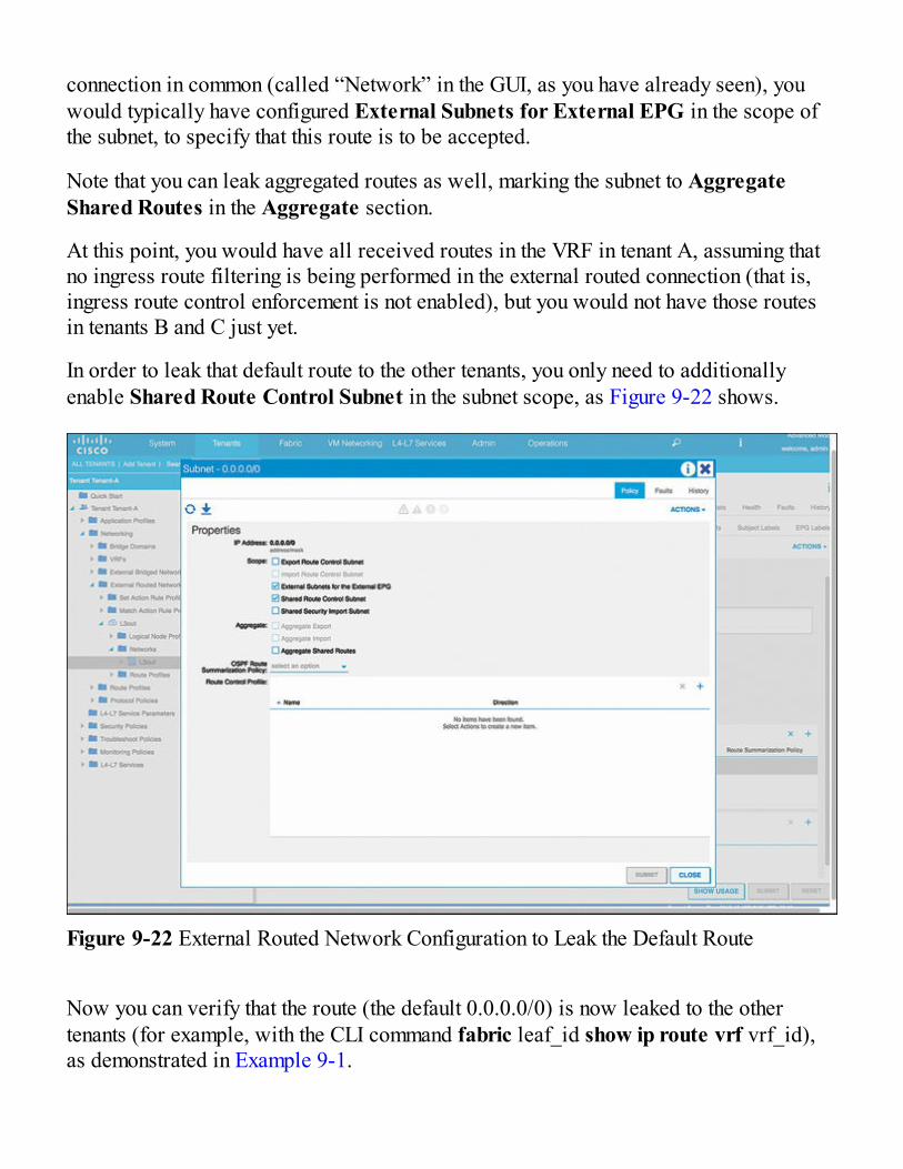
connection in common (called “Network” in the GUI, as you have already seen), youwould typically have configured External Subnets for External EPG in the scope ofthe subnet, to specify that this route is to be accepted.
Note that you can leak aggregated routes as well, marking the subnet to AggregateShared Routes in the Aggregate section.
At this point, you would have all received routes in the VRF in tenant A, assuming thatno ingress route filtering is being performed in the external routed connection (that is,ingress route control enforcement is not enabled), but you would not have those routesin tenants B and C just yet.
In order to leak that default route to the other tenants, you only need to additionallyenable Shared Route Control Subnet in the subnet scope, as Figure 9-22 shows.
Figure 9-22 External Routed Network Configuration to Leak the Default Route
Now you can verify that the route (the default 0.0.0.0/0) is now leaked to the othertenants (for example, with the CLI command fabric leaf_id show ip route vrf vrf_id),as demonstrated in Example 9-1.
||||||||||||||||||||
||||||||||||||||||||

As the output in Example 9-1 shows, 201 is the ID of a leaf that has endpoints in anEPG in the VRF in tenant B (otherwise the VRF is not deployed), and “Tenant-B:Tenant-B” is the VRF ID (the string before the colon is the tenant name, and the string after thecolon is the VRF name). The default route for the VRF in tenant B is reachable over anext hop that is in a different VRF, in tenant A.
Example 9-1 Verifying That a Route Is Leaked to Other TenantsClick here to view code image
apic# fabric 201 show ip route vrf Tenant-B:Tenant-B---------------------------------------------------------------- Node 201 (Leaf201)----------------------------------------------------------------IP Route Table for VRF “Tenant-B:Tenant-B”'*' denotes best ucast next-hop'**' denotes best mcast next-hop'[x/y]' denotes [preference/metric]'%<string>' in via output denotes VRF <string>0.0.0.0/0, ubest/mbest: 1/0 *via 192.168.61.11%Tenant-A:Tenant-A, vlan111, [20/1], 00:00:10, bgp-65100, external, tag 65100192.168.70.0/24, ubest/mbest: 1/0, attached, direct, pervasive *via 10.0.0.65%overlay-1, [1/0], 00:19:49, static192.168.70.1/32, ubest/mbest: 1/0, attached, pervasive *via 192.168.70.1, vlan106, [1/0], 01:13:26, local, localapic#
Note that with a normal EPG-to-L3-out relationship, you would typically associate theBD (to which the EPG is tied) to the L3 out, thus telling ACI over which external routednetwork the public subnets defined in the BD are to be advertised. In the case of ashared L3 out, there is no need for (and no possibility of) creating this relationshipbetween the BD and the external routed network.
Technet24||||||||||||||||||||
||||||||||||||||||||

Inter-Tenant ConnectivityThe fact that two tenants have been configured on a Cisco ACI fabric does notnecessarily mean that those tenants are completely isolated from each other. Obviously,if no data-plane multi-tenancy has been implemented, the question is not relevant: In amulti-tenant environment, purely from a management perspective, inter-tenantconnectivity is exactly the same as intra-tenant connectivity because you will have asingle VRF where all bridge domains belong, possibly under the common tenant.
The following sections cover the case where multiple VRFs have been configured. Youhave two possibilities to connect two VRFs to each other: inside the Cisco ACI fabricitself, and over an external network device.
Inter-VRF External ConnectivityThe first obvious choice when interconnecting two VRFs to each other is through anexternal IP device such as a router or a firewall, as Figure 9-23 depicts. This design issometimes known as a “Fusion router” and is quite common in multi-VRF data centers.
Figure 9-23 External Router or Firewall Interconnecting VRFs
The device connecting two or more VRFs to each other typically needs at least the
||||||||||||||||||||
||||||||||||||||||||

following network functionality:
Traffic filtering: Chances are that tenant traffic separation is motivated by securityrequirements, so you should only interconnect tenants through a device that providesa high level of security, such as a next-generation firewall.
Network address translation: Because tenants have their own VRF, they canpotentially have overlapping IP addresses. In this case, the device interconnectingthe tenants should be able to translate addresses in order to work around thisoverlap.
Each tenant would have its own external L3 network connection and would probablyhave a default route pointing to the outside (either statically or dynamically over arouting protocol). The external device can connect to the fabric over an 802.1Q trunkand would use IP subinterfaces to peer with the individual VRFs in the Cisco ACIfabric.
EPGs in one tenant that need to speak to other tenants only need to have a valid contractfor the external network connection in that tenant. From a tenant perspective, everythingthat does not belong to the VRF (such as IP addresses from other VRFs) will beclassified in the external EPG. Therefore, no contract is required between two EPGs indifferent tenants that need to communicate to each other, and all filtering required shouldbe done in the external device (or in the contracts between EPGs and external L3networks).
Inter-VRF Internal Connectivity (Route Leaking)In case there is a high amount of inter-tenant bandwidth, the requirements for theexternal router might be too expensive to satisfy in terms of bandwidth. This is oneexample of a situation in which it would be preferable to achieve the interconnection oftwo tenants directly inside the Cisco ACI fabric.
Getting Cisco ACI to interconnect two VRFs with each other is also possible withoutthe need of an external routing device, but additional configuration needs to be done(because otherwise VRFs are completely isolated from each other). In essence, it is thesame type of configuration that the earlier section “Shared External Network forMultiple Tenants” described, only that routes will not be leaked between an externalrouted network and an EPG, but between two EPGs, as Figure 9-24 illustrates.
Technet24||||||||||||||||||||
||||||||||||||||||||

Figure 9-24 Data Model for Internal Inter-VRF Connectivity
Essentially, what Cisco ACI needs to do is what the networking industry has dubbed“route leaking.” VRFs are considered to be hermetic routing containers, where no singleIP information is exposed to other VRFs. However, you can selectively open up fissuresto leak specific network prefixes between two VRFs.
In a traditional network, you would do that using the concept of export and import routetargets. In Cisco ACI, the object model greatly simplifies this operation, which boilsdown to two steps: signaling the subnets involved for leaking, and configuring a contractbetween the EPGs that need to communicate.
In the first place, the subnets of both EPGs need to be marked as Shared betweenVRFs so that Cisco ACI knows that they can be “leaked” to other VRFs. Whether theyare marked as Advertised Externally or as Private to VRF is not relevant for leakingthe subnets across tenants (that setting only has an impact for advertising subnets overexternal routed networks).
As you can see in Figure 9-24, the main construct signaling that routes need to beexchanged between VRFs is a contract, with the usual provider and consumer side. Forexample, if you have multiple tenants with their own VRFs accessing an area of thenetwork providing common services (such as Active Directory, Domain NameServices, and so on), you would typically configure the provider side in the commonservices area.
Remember that the contract needs to be created at the provider side (in this example,tenant A) because imported contracts can only be consumed, not provided.
||||||||||||||||||||
||||||||||||||||||||

You need to take care of two things: First, at the side providing the contract, the subnetneeds to be configured under the EPG instead of the standard configuration under thebridge domain, as Figure 9-25 illustrates. The reason is because when configuring thecontract between both EPGs, Cisco ACI will export the subnet configured under theEPG to the consumer VRF in order to have better control over which subnets are leakedto other VRFs and which subnets are not (in case there are multiple subnets configuredunder the BD). If you already had the subnet defined in the BD, you can just define thesame IP address at the EPG level.
On the consumer side, you can have the subnet configured either under the EPG or underthe bridge domain—it does not really matter. Therefore, in most situations, you willhave it under the bridge domain, which is how it is normally done.
Figure 9-25 Subnet Marked as Shared Between VRFs Defined Under the EPG(Provider Side)
After that, the only thing left to do is to create a contract between both EPGs. However,here we have a small difficulty: If we create the contract, say, in tenant A, how do wemake it visible to tenant B? The answer, as you probably have guessed, is throughexporting the contract. This way, contracts can be consumed and provided between
Technet24||||||||||||||||||||
||||||||||||||||||||

EPGs, without the need to use the common tenant.
As mentioned before, you need to create the contract in the tenant with the EPGproviding that contract. Note that at the consuming side, you need to consume thecontract by using the command Add Consumed Contract Interfaces in the Contractssection of the EPG. Do not forget to define the contract scope as Global.
And you obviously need to make sure there is no IP address overlap across both VRFs.For example, in the use case involving accessing common services from multipletenants, you might want to configure your common services with public IP addresses sothat they do not collide with the private IP address in use inside the tenants.
Route leaking is a powerful feature that has been used for decades (for example, inmany MPLS networks), and it can enable certain use cases that would not be possiblewithout it, such as the “shared services” VRF described later in this chapter. However,you should evaluate your design carefully if you decide to leverage route leakingbecause it might introduce some potential drawbacks:
Route leaking is a relatively complex and manual process; make sure your designdoes not require modifying leaked routes too often.
If you configure a complex route-leaking configuration, it might make theenvironment difficult to troubleshoot.
You can potentially disrupt a network when leaking the wrong routes to a VRF. Thatis another reason to keep changes to leaked routes to a minimum.
With leaked routes, you are essentially poking a hole into the wall that separates twoVRFs, so this might be considered a security risk.
L4-7 Services IntegrationChapter 10, “Integrating L4-7 Services,” deals with the insertion of Layer 4 to Layer 7network services, such as firewalls and load balancers. There are some specific detailsabout how to insert this type of network appliance in a multi-tenant environment, andthis section focuses on these details.
Inserting L4-7 network services in a multi-tenant ACI environment is not very differentfrom inserting services in a single-tenant design. Obviously, if you define all objects(L4-7 device, service graph templates, function profiles, and so on) inside of thecorresponding tenant, you will essentially be in the very same situation as the single-tenant design.
||||||||||||||||||||
||||||||||||||||||||

Note that the L4-7 device you define in the tenant might be a context you createdmanually (for an L4-7 device that supports a multicontext configuration such as CiscoASA), which means you are essentially doing a manual mapping between multi-tenancyat your L4-7 network service appliance and multi-tenancy at ACI.
Exporting L4-7 DevicesAlternatively, instead of configuring the L4-L7 services in the same tenant that is goingto consume them, you could centrally define a pool of L4-L7 services that can beconsumed by any tenant. For example, you might have some contexts pre-created in yourL4-7 device, but you have not decided yet to which tenant you will allocate it. Maybeyou just have a pool of firewalling or load-balancing contexts, and they are assigned tothe first tenant that asks for them.
As already mentioned, you could wait until a tenant needs L4-7 network services, andonly then define the L4-7 device. But you would need to keep separate documentationwith the L4-7 devices that you have already provisioned. An alternative would bedefining those L4-7 devices in a specific tenant (such as “common”), and only whenexporting those L4-7 devices to the tenant that requires the L4-7 functionality.
Note that even if an L4-7 device is defined in “common,” you will need to export to thetenant where you want to use it (where the service graph template is created). This isdifferent from other objects such as contracts, where tenants have immediate access toall instances created in “common” without having to explicitly export them.
Multi-Context L4-7 DevicesSome L4-7 devices support multi-context configuration, meaning that they can bevirtualized. For example, inside of a physical Cisco ASA firewall, you could havemultiple virtual firewalls, also called firewall contexts. Each context acts as anindependent device, with its own IP addresses, interfaces, routing table, and L4-7configuration. Sometimes these contexts will have their own management IP address, butnot necessarily.
The interfaces assigned to a context are typically virtual interfaces based on a VLAN sothat creating new contexts does not mean having to lay additional cabling to the L4-7devices.
Cisco ACI supports multi-context service integration, as described in Chapter 10. You
Technet24||||||||||||||||||||
||||||||||||||||||||

can therefore have ACI create the new context for the specific tenant you are insertingthe service for. For more information about working with multi-context L4-7 networkservice devices, refer to Chapter 10.
Use Cases for Multi-Tenancy ConnectivityThis chapter has described multiple options for configuring multiple tenants in CiscoACI, and you might be overwhelmed by all the different choices that ACI provides. Thissection covers multiple use cases and the recommended multi-tenancy option in eachcase. The list of use cases is not meant to be comprehensive: Chances are you will beconfronted with a slightly different design challenge. However, this section’s goal isexplaining the motivation behind each multi-tenancy design option in Cisco ACI.
ACI as Legacy NetworkIn other words, you use Cisco ACI as a traditional network that does not support amulti-tenancy concept. You might want to configure your new Cisco ACI fabric in thisway if your main goal is reducing complexity and you have no multi-tenancyrequirements whatsoever.
Essentially, you would deploy all ACI objects in the common tenant, using the defaultVRF in that tenant. Otherwise, there is not much to describe here from a multi-tenancyperspective. This design is not particularly recommended, but it is interestingconsidering that it’s the baseline from which most networks are evolving today, and it’sthe starting point when migrating a legacy network to Cisco ACI.
Granting Network Visibility to Other DepartmentsIf you often need to inform other departments about how the network is performing forthem, but you do not need any traffic separation, management-plane multi-tenancy is theway to go. In other words, you can configure multiple tenants as well as use securitydomains and role-based access control (RBAC) in order to grant read-only visibility tothose tenants for specific users. You would not need to have multiple VRFs, so all EPGswould relate to a single VRF (probably in the “common” tenant). This is very close tothe design discussed in the section “Logical Separation for Lines of Business,” earlierin this chapter.
Figure 9-26 shows an example of such a configuration, where network constructs
||||||||||||||||||||
||||||||||||||||||||

(bridge domains and VRFs) are defined in the common tenant, and EPGs are defined inseparate tenants. Note that this example would allow for separating web servers fromdatabases via contracts, even if they are sharing the same subnet.
Figure 9-26 Example with Management-Plane Multi-Tenancy and No Data-PlaneSeparation
As mentioned in previous sections, additional network segregation could beimplemented by adding separated physical domains for the production and test areas,and configuring different QoS policies for production and test, to make sure that onetraffic category will not be able to starve the other one.
Network Shared Across Organizations with SharedServicesThere can be multiple reasons why you may end up having multiple organizationssharing the same physical network, such as mergers and acquisitions as well as multiplelines of business with different IT requirements. In this case, you will have a fewtenants (not many) that will need a data-plane separation.
You could use different tenants, each with its own VRF, in order to support overlapping
Technet24||||||||||||||||||||
||||||||||||||||||||

IP addresses, and for the sake of simplicity share the external connections to the Internetacross all of them. For this purpose, you would configure a shared routed externalconnection, as described in this chapter. Figure 9-27 shows this design with twoorganizations, A and B.
Figure 9-27 Example Use Case with Two Organizations Sharing an External RoutedNetwork
Additionally, you could have a “shared services” area in your network (in the commontenant or in another one) from where you would provide, well, shared services to all theother tenants. This is where the configuration of EPG-to-EPG leaking comes into play:The provider EPG would be the one offering the “shared service” (DNS, ActiveDirectory, NTP, and so on), and the consumer offering each of the tenant EPGs thatrequire that service. Figure 9-28 shows this additional use case.
||||||||||||||||||||
||||||||||||||||||||

Figure 9-28 Use Case with Two Organizations Sharing an External Routed Network andAccessing a Common Services Area
External Firewall Interconnecting Multiple Security ZonesIn this use case, you need to have different security zones sharing the same networkinfrastructure, which under no circumstances are allowed to talk directly to each other.An example could be the implementation of a DMZ area and Intranet area using thesame physical network devices. For this use case, using dedicated VRFs for eachsecurity area might be the best solution.
Note that in theory you would not require multiple tenants, and you could configure allVRFs inside of the same tenant. For manageability purposes, you would probably wantto deploy each VRF in a dedicated tenant, though.
As Figure 9-29 shows, each tenant would then have its own routed external connectionor L3 out that would connect to a subinterface or a physical interface in an externalfirewall. Every packet between tenants would be routed (or dropped) externally by thefirewall, so no route leaking or inter-VRF communication is to be provided by thenetwork.
Technet24||||||||||||||||||||
||||||||||||||||||||

Figure 9-29 External Firewall Interconnecting Security Zones Represented bySeparated VRFs and Tenants
Service ProviderVery similar to the previous use case from a functional perspective, this use case needsto provide a network for multiple tenants with support for overlapping IP addressspaces. However, the number of tenants is probably much higher, and you will likelyneed to connect those tenants to an MPLS network. Intercommunication between tenantsis very unlikely.
In this case, having multiple tenants (each with its own VRF) leveraging the OpFlex-based integration with external routers such as the Nexus 7000 or ASR 9000 (refer toChapter 6 “External Routing with ACI” for more information) is a very attractive designoption that allows for quick, automated onboarding and decommissioning of customers.Figure 9-30 describes this setup.
||||||||||||||||||||
||||||||||||||||||||

Figure 9-30 Service Provider Design Including OpFlex-based Integration with theMPLS PE Router
If the service provider is offering L4-7 services to your customers, integration withmulticontext network service devices such as firewalls and load balancers wouldprovide automation for this part of the service, too.
SummaryAdministrator multi-tenancy is one of the functions that has been sorely missing inlegacy networks. VLANs and VRFs can provide multi-tenancy in the data plane, butCisco ACI is the first data center network that fully embraces multi-tenancy at all levels,including the management plane.
Cisco ACI has been conceived from the ground up to leverage multi-tenancy
Technet24||||||||||||||||||||
||||||||||||||||||||

technologies, and the APIC supports exposing these technologies accordingly.Combining multi-tenancy with role-based access control, you can define very granularlywhat admins are allowed (and not allowed) to do: Multi-tenancy defines which CiscoACI elements administrators can access, and role-based access control which actionsthey are allowed to perform on those elements.
In short, you can use two types of multi-tenancy in Cisco ACI. On one side, you can usemanagement multi-tenancy, where you separate the network configuration into differenttenants (or folders) and later assign administrators who can (or cannot) see thosetenants. And on the other side, you can use data-plane multi-tenancy, where workloadsbelonging to multiple tenants can have overlapping IP addresses, and packets from onetenant will never be sent to the other tenants. And of course, a combination of bothmanagement and data-plane multi-tenancy is possible.
Ideally, you would know when you start configuring Cisco ACI whether you want to layout your configuration in a multi-tenant structure. But even if you don’t, there are waysto migrate from a single-tenant configuration to multi-tenant configuration in ACI.
Lastly, you have ways to partially override the data-plane separation between tenants—for example, in order to share external connections across multiple tenants, or to defineexceptions where two tenants will be able to speak to each other over Cisco ACI.
||||||||||||||||||||
||||||||||||||||||||

Chapter 10
Technet24||||||||||||||||||||
||||||||||||||||||||

Integrating L4-7 Services
Inserting services in application flows that traverse the data center has been a challengefor many years. A combination of physical and virtual hosts, coupled with unpredictableflows, leaves many enterprises with inefficient or complex use of L4-7 resources. Hereare some of the challenges enterprises face:
How to give hosts equal access to services How to optimize the traffic flows to the service devices How to dynamically add and remove services as applications change How to avoid configuration drift across service devices How to remove stale configurations from service devices
In this chapter, we examine how ACI can help enterprises solve these concerns throughthe use of horizontal integration and open APIs, and with the help of ecosystem partners.We cover the following topics:
Services and ACI Ecosystem partners Managed versus unmanaged services Integrating various types of L4-7 services
||||||||||||||||||||
||||||||||||||||||||

Inserting ServicesA favorite quote from Joe Onisick in Cisco’s ACI business unit is, “For years, networkengineers have been like the MacGyvers of networking, using whatever tools they have,like bubble gum and duct tape, to get their application flows to service devices.”Although we engineers certainly do not use bubble gum and duct tape, we have all usedtools like virtual routing and forwarding (VRF) stitching and/or virtual LAN (VLAN)stitching to try and deliver the application flows where we want them to go. Theseconfigurations are very complex, hard to manage, and prone to human error. Many times,enterprises have to invest in larger-than-needed L4-7 service devices, because in orderto get some of their traffic inspected, they have to send the majority or all of their trafficto these devices. ACI has features and capabilities to allow enterprises a choice inexactly which traffic they would like to send to an L4-7 device, and it allows alldevices equal access to resources.
How We Do It TodayThe traditional security policy model for the data center is based on a static networktopology (bound to network connections, VLANs, network interfaces, IP addressing, andso on) and manual service chaining. This model requires policy configuration acrossmultiple security devices (firewalls, IPSs, and IDSs), slows application deployment,and is hard to scale because applications are dynamically created, moved, anddecommissioned in the data center. Other proposals attempt to take a virtualization-centric approach but fail to address applications not running as virtual machines.
Traditional models require days or weeks to deploy new services for an application.The services are less flexible, operating errors are more likely, and troubleshooting ismore difficult. When an application is retired, removing a service device configuration,such as firewall rules, is difficult. The scaling out/down of services based on the load isalso not feasible. Because all devices do not have equal access to resources, manytimes inserting services leads to inefficient traffic patterns through the data center. All ofthese things, coupled with human error, many times has enterprise engineers askingthemselves the following questions:
Have the VLANs been correctly allocated? Did we configure all the VLANs, or is one missing? Is the trunk configured properly? Could there be a VLAN mismatch between the hypervisor and switch?
Technet24||||||||||||||||||||
||||||||||||||||||||

Is there a firewall/load balancer/SSL misconfiguration?
The majority of enterprise firewall deployments for secure inspection can be broken upinto three scenarios:
Edge services: The firewall acts as a secure barrier or point of inspection betweenone network and another.
Security zones: The firewall acts as a secure barrier or point of inspection betweendifferent security zones such as production and the DMZ.
Application insertion: The firewall acts as a secure barrier or point of inspectionbetween a single tier or multiple tiers of an application.
Although VLAN and VRF stitching are supported by traditional service insertionmodels, the Application Policy Infrastructure Controller (APIC) can automate serviceinsertion while acting as a central point of policy control. The APIC policies manageboth the network fabric and services appliances. The APIC can configure the networkautomatically so that traffic flows through the services. The APIC can alsoautomatically configure the services according to the application’s requirements, whichallows organizations to automate service insertion and eliminate the challenge ofmanaging the complex techniques of traditional service insertion.
Let’s examine the ways in which services integrate with an ACI fabric. Following thepolicy model that we have discussed in previous chapters, the preferred way is to useACI policies to manage both the network fabric and services appliances such asfirewalls, load balancers, and so on. ACI then has the ability to configure the networkautomatically to redirect or allow traffic to flow through the service devices. Inaddition, ACI can also automatically configure the service devices according to theapplication service requirements. This policy, called a service graph, is an extension ofa contract and can be configured once and implemented many times, as shown in Figure10-1.
||||||||||||||||||||
||||||||||||||||||||

Figure 10-1 One Graph Template, Many Contracts, and the Same L4-7 Device
When a service graph is defined, the concept of functions is used to specify how trafficshould flow between the consumer EPG and the provider EPG, as well as what types ofdevices are involved in this communication. These functions can be defined as firewall,load balancer, SSL offload, and so on, and APIC will translate these function definitionsinto selectable elements of a service graph through a technique called rendering.Rendering involves the allocation of the fabric resources, such as bridge domains,service device IP addresses, and so on, to ensure the consumer and provider EPGs willhave all the necessary resources and configuration to be functional. Figure 10-2 showsan example of this.
Technet24||||||||||||||||||||
||||||||||||||||||||

Note: A provider (for example, a server) is a device (or set of devices) thatprovides services to other devices. A consumer (for example, a client) is a device(or set of devices) that consumes services from a provider. In relation to services,the provider is often thought of as the inside interface or the side facing the services,whereas the outside interface would be the consumer side or the side facing theclients.
Figure 10-2 Example of a Service Graph
After the graph is configured in the APIC, the APIC automatically configures theservices according to the service function requirements specified in the service graph.The APIC also automatically configures the network according to the needs of theservice function specified in the service graph, which does not require any change in theservice device.
A service graph is represented as two or more tiers of an application with the
||||||||||||||||||||
||||||||||||||||||||

appropriate service function inserted between, as shown in Figure 10-3.
Figure 10-3 Service Graph, Nodes, and Connectors
A service appliance (device) performs a service function within the graph. One or moreservice appliances might be required to render the services required by a graph. One ormore service functions can be performed by a single-service device, as shownpreviously in Figure 10-2 (the ADC device performs SSL offload and load balancing).
This allows the enterprise to create the intent-based policy that incorporates thebusiness needs for a network or application; then ACI can determine which devicesfrom its resource pools can meet the needs of the policy and implement them. This way,devices can be added to the pool when needed or if demand increases, as well asremoved from the pool for maintenance or when demand decreases. The definition ofyour services is not directly tied to a specific device. If you are leveraging non-vendor-specific configurations, you have the potential to move from one vendor’s hardwaresolution to another with ease. For example, if the policy specifies the need for afirewall that inspects or allows traffic on port 443, that firewall could be Checkpoint orCisco. Either way, ACI knows how to interact with the devices it has available throughits service graph and ecosystem partner integrations.
A service graph also provides the following additional operational benefits:
Automatic configuration of VLANs: Allocates VLANs to be used and configuresthem on both the L4-7 device and the network
Technet24||||||||||||||||||||
||||||||||||||||||||

Health score reporting: Provides information to ACI about the health of the deviceand of the function
Dynamic endpoint attach: Provides the ability to add endpoints discovered in theEPG to ACLs or load balancing rules (depends on the vendor)
Traffic redirect: Redirects specific ports to an L4-7 device
Similar to when we define an application profile, when we define a service graph, ACIcollects health information relating to the service graph. This is implemented indifferent ways by different vendors, but the service graph provides information to ACIabout the health of the device and of the function. In Figures 10-4 and 10-5, you see twoexamples of this functionality. Figure 10-4 depicts the outside interface of a firewallfailing. Figure 10-5 depicts two members of a real server load-balancing group losingconnectivity.
Figure 10-4 Example of Device Health Reporting
Figure 10-5 Example of Service Health Reporting
The ACI fabric tracks every device that is attached to it. A benefit of this function is that
||||||||||||||||||||
||||||||||||||||||||

ecosystem partners can choose to leverage this information to automatically update theconfiguration of their service device and reduce operational overhead. Figure 10-6shows an example pertaining to a load balancer, but this is available for securitydevices as well.
The Cisco ACI fabric can perform nonstateful load distribution across manydestinations. This capability allows organizations to group physical and virtual servicedevices into service resource pools, which can be further grouped by function orlocation. These pools can offer high availability by using standard high-availabilitymechanisms, or they can be used as simple stateful service engines with the loadredistributed to the other members if a failure occurs. Either option provides horizontalscale out that far exceeds the current limitations of the equal-cost multipath (ECMP),port channel features, and service appliance clustering, which requires a shared state.When enterprises couple this service resource pooling feature with ACI’s service-redirect capabilities, high availability and scale out of resources are taken to a newlevel.
Figure 10-6 Example of Endpoint Discovery and Automatic Configuration
Service graph redirect is a recent feature (as of 2.0) that offers many advantages forcustomers:
Technet24||||||||||||||||||||
||||||||||||||||||||

It eliminates the need to make the firewall or load balancer the default gateway. It avoids the need for more complex designs using virtual routing and forwarding(VRF) instances to implement L4-7 services.
It avoids the need to split Layer 2 domains (bridge domains) to insert, for instance, afirewall in the path.
It allows you to redirect only a subset of the traffic based on the protocol and port. It allows you to filter traffic between security zones in the same Layer 2 domain(bridge domain).
It allows you to scale the performance of the L4-7 device by distributing traffic tomultiple devices.
The following design considerations should be taken into account when deployingservice redirect:
Can be enabled for only one node in multinode service graphs. Support for both managed node and unmanaged node. Works only with GoTo devices. Transparent devices (such as IDS and IPS) are notsupported.
For non-EX leafs, service node cannot be under either the source or destination topof rack leaf switch.
Service node has to be connected to the ACI fabric via L2; both connectors shouldbe “L3 Adj.”
Endpoint data-plane learning should be disabled on BDs for service node interfaces. Both and active and standby service nodes should have the same vMAC.
One difference between the traditional service graph and the redirect option is that inthe first case, the contract in the graph allows traffic to go through the L4-7 device, butyou have to set up separate bridge domains to have routing or bridging in the fabricforward the traffic to the L4-7 device. With redirect, the contract rule forwards traffic tothe firewall regardless of the routing and bridging lookup results.
As mentioned previously, not only is this option easier from a configuration standpoint,but it allows you to scale across multiple devices and redirect only the traffic youwould like to send to the L4-7 device based on the protocol and port. Typical use casesinclude provisioning service appliances that can be pooled, tailored to applicationprofiles, scaled easily, and have reduced exposure to service outages. Policy-based
||||||||||||||||||||
||||||||||||||||||||

redirect simplifies the deployment of service appliances by enabling the provisioningconsumer and provider endpoint groups to be all in the same virtual redirect andforwarding (VRF) instance. Policy-based redirect deployment consists of configuring aroute-redirect policy and a cluster-redirect policy, as well as creating a service graphtemplate that uses the route- and cluster-redirect policies. After the service graphtemplate is deployed, use the service appliance by enabling endpoint groups to consumethe service graph provider endpoint group. This can be further simplified and automatedby using vzAny. While performance requirements may dictate provisioning dedicatedservice appliances, virtual service appliances can also be deployed easily using PBR.Figure 10-7 shows an example of this.
Figure 10-7 Service Graph Redirect to the Firewall Based on Protocol and Port
In this use case, you must create two subjects in the contract between EPGs. The firstsubject permits HTTP traffic, which then gets redirected to the firewall. After the trafficpasses through the firewall, it goes to the server endpoint. The second subject permitsSSH traffic, which captures traffic that is not redirected by the first subject. This trafficgoes directly to the server endpoint.
The order of the subjects in the contracts does not matter because the more specificfilter will take precedence. In the second example below, the traffic with port 443 isredirected as follows:
Contract:
Subject1: Permit 443 with service graph (PBR)
Technet24||||||||||||||||||||
||||||||||||||||||||

Subject2: Permit all without service graph (no PBR)
Symmetric policy-based redirect is also supported in EX hardware. Symmetric policy-based redirect configurations enable scaling out L4-7 device services, as shown inFigure 10-8. This feature allows enterprises to provision a pool of service appliancesso that the consumer and provider endpoint groups traffic is policy-based. The traffic isredirected to one of the service nodes in the pool, depending on the source anddestination IP equal-cost multipath (ECMP) routing prefix hashing.
Figure 10-8 Using Symmetric PBR to Scale Out ASA Virtual Firewalls
Managed vs. UnmanagedOnce you have decided to integrate services through the use of a service graph, youhave three main options available:
Network policy mode (or unmanaged mode): In this mode, Cisco ACI configuresonly the network portion of the service graph on the Cisco ACI fabric, which meansthat Cisco ACI doesn’t push configurations to the L4-7 devices. This mode does notrequire a device package (which we will explore shortly), but instead allows anetwork engineer to get application traffic to the devices more easily. This modealso takes care of all of the ACI fabric side of the configuration. All L4-7 deviceconfigurations will be completed by the device administrator.
||||||||||||||||||||
||||||||||||||||||||

Service policy mode (or managed mode): In this mode, Cisco ACI configures thefabric and the L4-7 device (VLANs and device configuration), and the APICadministrator enters the L4-7 device configurations through APIC.
Service manager mode: In this mode, the firewall or load-balancer administratordefines the L4-7 policy, Cisco ACI configures the fabric and the L4-7 deviceVLANs, and the APIC administrator associates the L4-7 policy with the networkingpolicy.
ACI L4-7 service integration is available to help streamline service integration in thedata center, not add complexity. That being said, if all your enterprise needs is atopology with a perimeter firewall that controls access to the data center, and if thisfirewall is not decommissioned and provisioned again periodically, you should use thenetwork policy mode deployment.
With the service graph in service policy mode, the configuration of the L4-7 device ispart of the configuration of the entire network infrastructure, so you need to consider thesecurity and load-balancing rules at the time that you configure network connectivity forthe L4-7 device. This approach is different from that of traditional service insertionwhere you can configure the security and load-balancing rules at different times beforeor after you configure network connectivity. In this mode, you will deploy all of theseconfigurations simultaneously. If you need to make changes to the firewall or loadbalancer, you most likely will have to delete and redeploy the service graph.
Note: Although deleting and redeploying a service graph sounds like a lot of work,remember this system was designed around open APIs and this task can becompleted in seconds with programmability.
With the service manager mode (see Figure 10-9), the interactions with the L4-7 devicedepend on the vendor management tool. Cisco ACI references a policy defined on theL4-7 management tool. This tool may let you make changes to the firewall or load-balancer configurations without the need to redeploy the service graph. Most enterprisesare gravitating toward this option. It offers the best of both worlds. Serviceadministrators configure the policies using the tools they are comfortable with, whileACI orchestrates the known-good policy while protecting against human error andconfiguration drift.
Another option, which is the least-preferred option, is to perform manual serviceinsertion. In Cisco ACI, you also can configure service insertion without a service
Technet24||||||||||||||||||||
||||||||||||||||||||

graph.
To do so, you need to create multiple bridge domains that operate just like VLANs, andyou can configure EPGs to connect virtual or physical appliances.
Figure 10-10 shows a simple multinode service insertion design. The configurationconsists of multiple bridge domains and EPGs. Bridge Domain 1 has an EPG to whichthe router and the firewall outside interface connect. Bridge Domain 2 has one EPG toconnect the inside interface of the firewalls and the client-side interface of theApplication Delivery Controller (ADC) device. Bridge Domain 3 has an EPG for theserver-side interface of the ADC device and multiple EPGs for the servers, and theEPGs are connected through contracts.
Figure 10-9 Service Manager Mode
||||||||||||||||||||
||||||||||||||||||||

Figure 10-10 Multinode Service Insertion Design
ACI can integrate with any vendor’s device in manual and or network policy mode.Manual mode, as shown in Figure 10-10, involves stitching things together the sameway we have for years and should only be used as a last resort. Network policy modeautomates the configuration of the network and allows traffic to flow through deviceseasily. Service policy mode and service manager mode are where things start to getreally interesting. The automation, insertion, and cleanup of devices/policy with healthmonitoring requires an advanced level of API interaction and integration called adevice package.
A device package leverages our open API and defines which L4-7 parameters can beconfigured from the APIC. The vendor of the security or service appliance defines thesyntax of these L4-7 parameters, and this syntax reflects the syntax used by the firewallor ADC administrator when the device is configured directly.
The APIC communicates with the firewalls or load balancers to render the graphdefined by the user. For Cisco ACI to be able to talk to firewalls and load balancers, itneeds to speak to their APIs. The administrator needs to install plug-ins called devicepackages on the APIC to enable this communication. Installation of device packages canbe performed by the infrastructure administrator role using the L4–L7 Services menuand the Packages sub-menu, as shown in Figure 10-11.
Technet24||||||||||||||||||||
||||||||||||||||||||

Figure 10-11 Device Package
The device package (see Figure 10-12) is a .zip file that includes a description of thedevice and lists the parameters it is exposing for the APIC configuration.
Figure 10-12 Device Package and Southbound API
Specifically, a device package includes the scripts that allow Cisco ACI to talk to thisdevice, as shown in Table 10-1.
||||||||||||||||||||
||||||||||||||||||||

Table 10-1 Device Package ContentsDevicespecification
An XML file that defines the following: Device properties:
Model: Model of the device
Vendor: Vendor of the device
Version: Software version of the device Functions provided by a device, such as load balancing, contentswitching, and SSL termination
Interfaces and network connectivity information for each function Device configuration parameters Configuration parameters for each function
Device script A Python script that interacts with the device from the APIC. APICevents are mapped to function calls that are defined in the devicescript. A device package can contain multiple device scripts. A devicescript can interface with the device by using REST, SSH, or anysimilar mechanism.
Functionprofile
Function parameters with default values that are specified by thevendor. You can configure a function to use these default values.
Device-levelconfigurationparameters
A configuration file that specifies parameters that are required by adevice. This configuration can be shared by one or more graphs using adevice.
Over time, device packages will need to be maintained and upgraded. It is important toknow the following:
A device cluster can be managed by only one package at any time. The node in the graph and associated device cluster should point to the samepackage.
A minor version upgrade is considered as the replacement for the existing packagefor the device.
A minor version upgrade is nondisruptive and there should be no impact for existinggraphs or device clusters.
A new major version is considered a new device package.
Technet24||||||||||||||||||||
||||||||||||||||||||

The existing package is not impacted. The existing graph instances continue to use the previous major version (parallelupgrades and testing are possible).
Switching from an old graph/cluster to a new major version package is disruptiveand should be scheduled during a maintenance window.
An ecosystem partner’s device package is maintained by that third-party vendor (forexample, Citrix, F5, Checkpoint, or Palo Alto). Cisco maintains the device packagesrelated to its devices. Likewise, the release of new features and functionality is up to thevendor that owns the package. Certain device packages may have dependencies orfunctionality tied to particular versions of ACI as well.
Role-based access control (RBAC) is also available to allow enterprises to controlaccess to which users can import or view device packages, as well as who has accessto create or export devices and/or policy. Table 10-2 outlines the predefined roles andpermissions.
Table 10-2 RBAC Attribute Privileges
RBACAttribute
Privilege
NW-SVC-DEVPKG
Allows an admin to import a package. Only the infra admin can import apackage. Tenant admins can only see the packages imported under infra.This gives read-only access to the tenant admin.
NW-SVC-POLICY
Allows a tenant admin to create graph and other related configurationmanaged objects.
NW-SVC-DEVICE
Allows a tenant admin to create device cluster and other relatedconfiguration managed objects.
NW-SVC-DEVSHARE
Allows a tenant to export the device cluster to another tenant.
Note: The credentials are in both the logical device (that is, the clusterconfiguration) and the concrete device (that is, the physical device configuration),so if you are changing credentials, be sure to change them in both places.
||||||||||||||||||||
||||||||||||||||||||

Ecosystem PartnersCisco ACI has a very mature ecosystem of over 65 partners and growing. ACI isdesigned as an open architecture using APIs to horizontally integrate with these partnersfor not only configuration and management use cases but potentially automated responseto data center events as well. The ACI ecosystem is designed to help customers use,customize, and extend their existing IT investments with Cisco ACI offerings in thefollowing areas:
Orchestration, automation, and management Configuration and compliance Monitoring and diagnostics Storage and virtualization Traffic flow and analysis Security Network services
This book will not be able to address all of the possible use cases that may be found inenterprise environments. However, it will focus on some of the more prevalent usecases and configurations to help build a foundational knowledge to move forward with.
Table 10-3 and Table 10-4 provide a few of the ecosystem partner enterprises thatcommonly integrate with ACI. These ecosystem partners include but are not limited tothe vendors listed in Table 10-3.
Table 10-3 ACI Security Enforcement L4-7 Integration
EcosystemPartner
NetworkPolicy
ServicePolicy
Service Manager
Cisco Security ✓ ✓ Cisco ASA ✓ FMC (NGIPS andNGFW)
Palo Alto ✓ X ✓
Check Point ✓ X ✓vSec
Fortinet ✓ ✓ RoadmapFortiManager
Technet24||||||||||||||||||||
||||||||||||||||||||

Table 10-4 ACI ADC L4-7 Integration
Ecosystem Partner Network Policy Service Policy Service Manager
F5 ✓ XNo longer supported
✓iWorkflow
Citrix ✓ ✓ ✓MAS
Radware ✓ ✓ ✓vDirect
A10 ✓ ✓ ✓aGalaxy
Avi ✓ X RoadmapAvi Controller
Note: Additional ecosystem partner information can be found athttps://www.cisco.com/c/en/us/solutions/data-center/data-center-partners/ecosystem-partner-collateral.html.
Before choosing an integration option, enterprises also need to consider how the rolesand responsibilities as well as the operational management model for their services maychange.
Management ModelThe service graph introduces multiple operational models for deploying L4-7 services.
The service graph in network policy mode follows a traditional operational model inwhich the configuration of L4-7 devices consists of the following steps:
1. The network administrator configures the ports and VLANs to connect the firewallor the load balancer.
2. The firewall administrator configures the ports and VLANs.3. The firewall administrator configures the ACLs and other components. As shown in
Figure 10-13, with the Cisco ACI service graph in network policy mode, the
||||||||||||||||||||
||||||||||||||||||||

network administrator configures the fabric but not necessarily the firewall.
Figure 10-13 Cisco ACI Service Graph with the Network Policy Mode DeploymentType: The Network Administrator Manages the Fabric but Not the Firewall or LoadBalancer
In addition, with the Cisco ACI service graph in network policy mode, the securityadministrator administers the firewall through a management tool designed for the L4-7device (see Figure 10-14).
Technet24||||||||||||||||||||
||||||||||||||||||||

Figure 10-14 With the Network Policy Mode, the Security Administrator Manages theFirewall Directly or Through a Management Tool
With the Cisco ACI service graph in service policy mode, the management modelchanges, as illustrated in Figure 10-15. The network administrator needs to apply theconfiguration for the network as well as for the firewall through the APIC, and the L4-7administrator needs to provide the L4-7 configuration to the network administrator. Thisconfiguration is then assembled as a function profile.
The APIC then programs both the fabric and the L4-7 device. The L4-7 administratorcan read the configuration from the L4-7 management tool but cannot make changes tothe configuration directly.
With the Cisco ACI service graph in service manager mode, the L4-7 administratordefines the L4-7 configurations through the L4-7 management tool instead of configuringfunction profiles with L4-7 parameters. The APIC administrator configures the servicegraph and references the L4-7 policy defined by the L4-7 administrator. Figure 10-16illustrates this concept.
Based on the information in this section, you should now understand at a high level theways in which you can use services with ACI. You should be familiar with these designscenarios:
Manual service insertion
||||||||||||||||||||
||||||||||||||||||||

Network policy mode (unmanaged, no device package) Service policy mode (managed mode, device package) Service manager mode (managed mode, device package + third-party OEM devicemanagement tool)
Figure 10-15 Cisco ACI Operational Model with Service Policy Mode: Network andL4-7 Configuration Are Managed Through APIC
Technet24||||||||||||||||||||
||||||||||||||||||||

Figure 10-16 Cisco ACI Operational Model with Service Manager Mode
We have examined the impact of these modes. We have also examined the managementmodel for each of these scenarios. Figure 10-17 provides a decision tree thatsummarizes some of the decision points we have discussed earlier in this section. Manyenterprises use it as a starting point when they are considering service integration withACI.
||||||||||||||||||||
||||||||||||||||||||

Figure 10-17 ACI Service Mode Decision Tree
In the following section, we continue to explore some of the components in managedservice integration.
Functional ProfilesWith any device, performing manual configuration over and over again can be tedious,so Cisco ACI provides the function profile feature, which allows you to define acollection of L4-7 parameters that you can use when you apply a service graph template.You can create one or many functional profiles. Function profiles can also beprepopulated and provided by the L4-7 device vendor.
When you use the service graph function of Cisco ACI in service policy mode, you enterall the configurations for the fabric and for the service device as part of the same L4-7configuration process. As a result, you must enter L4-7 parameters that configure thefirewall and/or the load balancer. These parameters can be items including but notlimited to the following:
Technet24||||||||||||||||||||
||||||||||||||||||||

Host Name Network Time Protocol Server Primary DNS Port Channel Configuration
This process can be time consuming, particularly if you want to decommission a deviceand redeploy it in a different way. As shown in Figure 10-18, the function profile solvesthis problem.
Figure 10-18 Choosing a Functional Profile for Device Configuration
With a function profile, you can create a collection of L4-7 configuration parametersthat you can use when you apply a service graph template. Functional profiles can beused to define standard policy for L4-7 devices in your environment. You also have theflexibility of being able to keep L4-7 parameters inside certain objects, which allowsyou to configure a single service graph and then reuse the graph for different tenants orEPGs with a different configuration. L4-7 parameters can be stored under the providerEPG, bridge domain, application profile, or tenant. When a graph is instantiated, theAPIC resolves the needed configuration for a service graph by looking up theparameters in various places. Service graph rendering looks for parameters in thisorder: function profile > AbsNode > EPG > application profile > tenant. By default, L4-7 parameters are placed under the provider EPG if you use the Apply Service GraphTemplate Wizard.
Note: The bridge domain configuration location is being phased out. Tenant andapplication profile are the preferred options.
||||||||||||||||||||
||||||||||||||||||||

If the tenant contains multiple service graph instances with different provider EPGs, theL4-7 parameters are stored in different places by default. You can place them in oneeasy-to-find place (under the application profile or tenant). For example, if you use thesame ASA service graph on the same ASA appliance for multiple contracts, the L4-7parameters are placed under the Web1 EPG and the Web2 EPG (see Figure 10-19),which are different APIC GUI locations.
Figure 10-19 Parameters Under the Provider EPG
If you want, for management and troubleshooting simplicity, you can place theparameters under the application profile or tenant (see Figure 10-20).
Technet24||||||||||||||||||||
||||||||||||||||||||

Figure 10-20 Parameters Under the Provider Application Profile or Tenant
To further manage parameters and enforce standard policy, each parameter youconfigure with a functional profile has the ability to be set as Mandatory, Locked, orShared, as shown in Figure 10-21.
Figure 10-21 Functional Profile Configuration Parameters
The setting of these three parameters has the following effect on the final configuration
||||||||||||||||||||
||||||||||||||||||||

parameters of the device:
Mandatory: When a parameter is set to “true,” the configuration item is mandatory.This option is used when the administrator wants to force the user to specify a valueor parameter.
Locked: When this is set to “true,” the parameter specified in the functional profilewill be used instead of the parameter defined at the EPG, BD, application profile,or tenant level.
Shared: If this option is set to “true,” the parameter value in the function profile willbe used if no parameter value is set under the EPG, bridge domain, applicationprofile, or tenant. If a parameter is defined under the EPG, bridge domain,application profile, or tenant, the value in the function profile will not be used.
Using the Locked and Shared parameters together is very useful for managing andmaintaining device parameters. When these two fields are both set to “true” forparameters in the functional profile, a change in the functional profile will flow to theindividual device, even when the service graph has already been deployed. Here’s anexample:
Step 1. Create a function profile that has the parameter “shared=true” (for example, IPaddress 192.168.1.100).
Step 2. Create a service graph using the function profile.
Step 3. Apply the service graph to a subject in the contract.IP address 192.168.1.100 is configured on ASA.
Step 4. Change the function profile parameter 192.168.1.100 to 192.168.1.101.IP address 192.168.1.101 is configured on ASA.
Note: Without “shared=true”, if a parameter in the function profile is updated, it’snot pushed to the concrete device configuration. This feature can be a very powerfultool, but it should be used with care to avoid unintentionally updating productiondevices by changing a parameter in the functional profile.
Now that we have explored the pieces and parts that allow us to orchestrate services inACI, let’s take a moment to understand the five steps required to implement services inACI (see Figure 10-22):
Technet24||||||||||||||||||||
||||||||||||||||||||

Step 1. Define the L4-L7 device or pool.
Step 2. Create a service graph template.
Step 3. Attach the service graph to a contract.
Step 4. Create the device selection policy used to select a service device.
Step 5. Configure the service node with predefined parameters.
Figure 10-22 Steps to Insert Services
The functional profile of a device is also the base configuration of the device, meaningthat if you plan to apply a template configuration later on that uses a specific feature,that feature must first be enabled in the functional profile.
||||||||||||||||||||
||||||||||||||||||||

Security for All HostsThe Cisco ACI Security Solution uses a holistic, systems-based approach foraddressing security needs for next-generation data center and cloud environments.Unlike alternative overlay-based virtualized network security solutions, which offerlimited visibility and scale and require separate management of underlay and overlaynetwork devices and security policies, the Cisco ACI Security Solution uniquelyaddresses the security needs of the next-generation data center by using an application-centric approach and a common policy-based operations model while helping ensurecompliance and reducing the risk of security breaches.
The Cisco ACI Security Solution enables unified security policy lifecycle managementwith the capability to enforce policies anywhere in the data center across physical andvirtual workloads, including containers. It offers complete automation of Layer 4through 7 security policies and supports a defense-in-depth strategy with broadecosystem support while enabling deep visibility, automated policy compliance, andaccelerated threat detection and mitigation. Cisco ACI is the only approach that focuseson the application by delivering segmentation that is dynamic and application centered.
Here are the main features and benefits of Cisco ACI security covered in this section:
Application-centric policy model: Cisco ACI provides a higher-level abstractionusing endpoint groups (EPGs) and contracts to more easily define policies using thelanguage of applications rather than network topology. The Cisco ACI whitelist-based policy approach supports a zero-trust model by denying traffic between EPGsunless a policy explicitly allows traffic between the EPGs.
Unified Layer 4 through 7 security policy management: Cisco ACI automates andcentrally manages Layer 4 through 7 security policies in the context of anapplication using a unified application–centric policy model that works acrossphysical and virtual boundaries as well as third-party devices. This approachreduces operational complexity and increases IT agility without compromisingsecurity.
Policy-based segmentation: Cisco ACI enables detailed and flexible segmentationof both physical and virtual endpoints based on group policies, thereby reducing thescope of compliance and mitigating security risks.
Automated compliance: Cisco ACI helps ensure that the configuration in the fabricalways matches the security policy. Cisco APIs can be used to pull the policy andaudit logs from the Cisco Application Policy Infrastructure Controller (APIC) andcreate compliance reports (for example, a PCI compliance report). This feature
Technet24||||||||||||||||||||
||||||||||||||||||||

enables real-time IT risk assessment and reduces the risk of noncompliance fororganizations.
Integrated Layer 4 security for east-west traffic: The Cisco ACI fabric includesa built-in distributed Layer 4 stateless firewall to secure east-west traffic betweenapplication components and across tenants in the data center (DC).
Open security framework: Cisco ACI offers an open security framework(including APIs and OpFlex protocol) to support advanced service insertion forcritical Layer 4 through 7 security services such as intrusion detection systems(IDS) and intrusion prevention systems (IPS), and next-generation firewall services,such as the Cisco Adaptive Security Virtual Appliance (ASAv), the Cisco ASA5585-X Adaptive Security Appliance, and third-party security devices, in theapplication flow regardless of their location in the DC. This feature enables adefense-in-depth security strategy and investment protection.
Deep visibility and accelerated attack detection: Cisco ACI gathers time-stampednetwork traffic data and supports atomic counters to offer real-time networkintelligence and deep visibility across physical and virtual network boundaries.This feature enables accelerated attack detection early in the attack cycle.
Automated incident response: Cisco ACI supports automated response to threatsidentified in the network by enabling integration with security platforms usingnorthbound APIs.
We will continue to examine these benefits in the following sections.
||||||||||||||||||||
||||||||||||||||||||

Building an End-to-End Security SolutionIn a perfect world, your enterprise’s security policies would be enforced from the enduser, across the WAN or campus, and into your cloud/DC (private or public), down tothe individual server. Cisco has made that world into a reality. The architecture andsolution have already been developed and integrated to allow these security dreams tobecome a reality. We have the capability to define and enforce security policy in thecampus and wide area network with Identity Services Engine and APIC-EM (software-defined WAN). Cisco has recently launched further capabilities for intent-basedenforcement in its DNA products or software-defined access solution. Cisco ACI hasthe capability to define and enforce security policy on both physical and virtualworkloads (VMware, Microsoft, Red Hat, OpenStack, Kubernetes) in the DC, or in thecloud with its new ACI anywhere announcement. Furthermore, ISE, APIC-EM, and ACIintegrations have already been developed so customers can leverage existingintellectual property and share policy between solutions so we can truly have onepolicy that flows across multiple enforcement platforms.
Through this integration, the security group tags (SGTs) in a TrustSec-enabled networkcan be converted to endpoint groups (EPGs) in the ACI data center network, and theEPGs from ACI can be converted to SGTs in the enterprise network. Thus, CiscoIdentity Service Engine (ISE) enables the sharing of consistent security policy groupsbetween TrustSec and ACI domains. This is shown in Figure 10-23.
Figure 10-23 TrustSec Groups Shared Between ISE and ACI
Technet24||||||||||||||||||||
||||||||||||||||||||

To enable groups from the ACI domain to be used in the TrustSec domain, ISE willsynchronize internal EPGs from the APIC-DC controller and create correspondingsecurity groups in the TrustSec environment. ISE will also synchronize security groupsand associated IP-to-security-group mappings with the APIC-DC external endpoints (L3Out) and subnets configuration. This integration creates an environment where a user(shown as “Auditor” in the figure) logs in to the network, is authenticated based onusername and device type, and assigned custom access that is enforced on a hop-by-hopbasis from end to end across the architecture. Figure 10-24 shows the resultingarchitecture.
Figure 10-24 End-to-end Policy Enforcement Campus (ISE) to DC (ACI)
The final hurdle to getting to this end-to-end security environment is understanding theapplications that exist in the data center and how they are used. This knowledge iscrucial so that the correct security policies can be can be created, maintained, andenforced with confidence, knowing that there will be no negative effects to yourproduction environment. Tetration Analytics can do all this and more (see Figure 10-25).
||||||||||||||||||||
||||||||||||||||||||

Figure 10-25 Cisco Tetration Ingests Information from Your Servers and Network andAutomatically Creates Whitelist Policy
Tetration will automatically map your application dependencies through pervasivevisibility and machine learning. Tetration consumes information and metadatasimultaneously from your servers and network. It uses contextual information from yourenvironment, such as your pre-existing ISE security groups, to build and define intent-based security policies, which you can then take and import into ACI. ISE and ACI willthen enforce these policies in each of their domains. All of this is shown in Figure 10-26.
Tetration then becomes a centralized platform to manage, monitor, and update policy.The policies themselves become much easier to manage, because we have the ability todo so with groups or tags instead of port numbers and IP addresses. An enterprise onlyneeds to tag their devices and then create policy based on those tags or groups. In theexample in Figure 10-27, we imported the tags from ISE and created policy based ontags named “Contractors and Auditors” and “Production”. With one simple rule,“Contractors are denied access to Production,” we are able to create a very powerfulpolicy. When this policy is exported from Tetration, the appliance figures out all of theIP addresses and port numbers that need to be included in the rule set so that a securityplatform such as ACI understands how to enforce the policy. Tetration then tracks thepolicies to make sure that they have been successfully implemented and are beingcomplied with as intended. If, for some reason, traffic is escaping a policy, Tetrationand ACI can help you pinpoint where the misconfiguration is.
Technet24||||||||||||||||||||
||||||||||||||||||||

Figure 10-26 Single Policy Created by Tetration and Shared with ACI and ISE
Figure 10-27 Using Tags or Groups to Create Intent-based Policy, Which Can BeImported into Security Platforms
||||||||||||||||||||
||||||||||||||||||||

Note: If you would like more in-depth information on ISE+ACI, refer to “CiscoConfiguration Guide: TrustSec – ACI Policy Plane Integration” athttps://tinyurl.com/ISEplusACI.
Note: If you would like additional information on Tetration, visitwww.cisco.com/go/tetration.
No matter how you have designed your security policies, you have the ultimate choiceregarding where, when, and at what level you want your policies enforced. You maychoose to enforce L4 security policy in the switching hardware or the hypervisor. Youmay want application-specific inspections between one tier of an application but notanother. You can bring in any service (virtual or physical) from any vendor at any time.In the following sections, we examine specific integration examples of the followingdevice types:
Firewall Load balancer IDS/IPS
Each of these device types can be configured in multiple deployment modes. Cisco ACIsupports these deployment modes for L4-7 devices with the service graph:
Go-to mode (also known as routed mode): In this mode, the default gateway for theservers is the L4-7 device.
Go-to mode with service graph redirect: In this mode, the default gateway for theservers is the Cisco ACI bridge domain, and traffic is sent to the L4-7 device basedon the contract configuration between EPGs. Service graph redirect is the preferreddeployment mode for the service graph when Cisco Nexus 9300 EX and FXplatform switches are used.
Go-through mode (also known as transparent mode or bridged mode): In thismode, the default gateway for the servers is the client-side bridge domain, and theL4-7 device bridges the client-side bridge domain and the server-side bridgedomain.
One-arm mode: In this mode, the default gateway for the servers is the server-sidebridge domain, and the L4-7 device is configured for source NAT (SNAT).
Technet24||||||||||||||||||||
||||||||||||||||||||

Routed mode (go-to mode): The simplest way to deploy a service graph in routedmode is to use NAT on the L4-7 device. Cisco ACI also supports service devicesdeployed in routed mode with either static or dynamic routing by connecting the L4-7 device to an L3 Out.
Service devices that support routed mode designs integrate with ACI based on theseconfigurations:
Routed mode with outside Layer 2 bridge domain: In this design, the outside of theservice graph connects to a Layer 2 bridge domain. The routing to the servicedevice is implemented with an external routing device.
Routed mode with L3 Out and NAT: In this design, the service graph connects tothe outside network through routing provided by the Cisco ACI fabric. This designcan be implemented if the service device implements NAT, as in the case of a loadbalancer or in the case of a firewall that is translating the internal IP addresses.
Routed mode in which the L3 Out interface performs Layer 3 peering with theL4-7 device: In this design, the L4-7 device doesn’t use NAT to translate theaddresses of the servers. Therefore, you need to configure static or dynamic routingon the L3 Out interface with the L4-7 device.
Routed mode with policy-based redirect (PBR) to the L4-7 device: In this design,you don’t need L3 Out or NAT on the L4-7 device. The Cisco ACI fabric redirectstraffic to the L4-7 device based on contracts.
Routed mode with outside Layer 2 bridge domain: In this design, the L4-7 servicemay or may not be configured to translate the IP addresses of the servers, as may bethe case with a firewall configuration. In addition, in this design you use an externalrouter to provide the default gateway to the service device.
Regardless of which vendor or which type of integration you are going to use, somepreparation work needs to be completed before you can integrate an L4-7 device. Thesepreparation steps are as follows:
Step 1. Create the necessary physical and virtual domains. These are the VLANdomains that will be used when integrating with the device. Make sure you usephysical domains (for physical appliances) or the necessary virtual domain(VMM for virtual appliances), or both. Theses domains will be used in theconfigurations and should be mapped to the ports where the service devicesare going to attach.
Step 2. Create the necessary fabric access policies. These policies include the best-
||||||||||||||||||||
||||||||||||||||||||

practice configurations for how the service appliances will physically connectto the ACI leaf.
Step 3. Use the following basic configuration of device mode for the firewall device: Configure contexts if supported. Transparent/routed. Management IP address and connectivity. Management protocol (Enable: SSH, HTTP, HTTPS). Configure credentials.
Step 4. Import the device package.
Step 5. Create the tenant where you will be deploying the service.
Step 6. Create the VRF where you will be deploying the service.
Step 7. Create the necessary bridge domains/VRFs.Here are the most common bridge domain settings for L4-7 devices (see Figure10-28): Do not use IP learning when using PBR. Do not use unicast routing in transparent mode.
Step 8. Create EPGs and contracts.
Technet24||||||||||||||||||||
||||||||||||||||||||

Figure 10-28 Bridge Domain Configuration Recommendations
Note: ACI does have multicontext vendor support. Every vendor’s implementationis different. For the ASA, you will need to set up multiple contexts beforeconfiguration.
Note: If you are using Cisco ASA, then ASAv must be deployed on an ESXi that isparticipating in a VMware VDS VMM domain.
We will also explore integration examples from multiple vendors such as Cisco, Citrix,and F5.
||||||||||||||||||||
||||||||||||||||||||

Integrating FirewallsThe first device integration we will examine in depth is firewall integration. The mostcommon insertion points for a firewall in the fabric are at the perimeter of the fabric,between security zones, or between application tiers where a more granular level ofprotocol inspection may be needed. Many customers use larger hardware-basedfirewalls for perimeter applications, and virtual firewalls for inside the fabric. In anycase, you will need to decide in which mode the device will be implemented.
For the firewall function, service graph deployment can be configured with one of thefollowing modes:
GoTo: The L4-7 device is a Layer 3 device that routes traffic; the device can beused as the default gateway for servers or the next hop.
GoThrough: The L4-7 device is a transparent Layer 2 device; the next hop or theoutside bridge domain provides the default gateway.
One of the easiest and most straightforward configurations of a firewall in the ACIfabric is to use the firewall as the Layer 3 gateway for all of the devices, and to use theACI fabric for L2 functionality. In this design, as shown in Figure 10-29, the client EPGis associated with BD1, which is configured in L2 mode only. The Web EPG isassociated with BD2, which is also configured as L2 only. Both bridge domain 1 and 2are associated with VRF1, but this association is only in place to satisfy the objectmodel. It does not have any operational significance. The clients and the web serverswill have the firewall external and internal interfaces, respectively, configured as theirdefault gateway. A contract will be used between the Client EPG and Web EPG toallow communication and invoke services.
Technet24||||||||||||||||||||
||||||||||||||||||||

Figure 10-29 L3 Firewall as the Gateway for All Devices
In the upper-right part of Figure 10-29, you will notice that Unicast Routing is set to Noon the adjacency settings between the firewall and the fabric. They are set to Nobecause the fabric is operating at L2 only and the service device is not peering with thefabric. The graphic on the right of Figure 10-29 shows the logical traffic flow fromclient to web server.
The second common design option for an L3 firewall that we will examine is toleverage both the firewall and ACI fabric in an L3 capacity. This design requires thedevices internal to the firewall to leverage the firewall as the gateway, but allows amuch more scalable and operationally efficient design to be leveraged for the devicesthat are external to the firewall. As shown in Figure 10-30, the firewall can peer withthe fabric internally or directly with a specific L3 Out and operate with or withoutnetwork address translation (NAT). By creating this peering relationship and usingrouting (the preferred method) or static routes, the fabric is able to determine whichdevices and subnets exist behind the firewall and route traffic in a bidirectional manner.
||||||||||||||||||||
||||||||||||||||||||

Figure 10-30 GoTo Firewall with L3 Peering
In Figure 10-30, multiple bridge domains have been created. In both the top and bottomexample, two bridge domains have been created for the inside and outside interface ofthe firewall. Bridge domain 2 is operating in L2-only mode and is associated with theweb clients and the inside interface of the firewall. The devices in the Web EPG areconfigured to use the firewall as their gateway. The external firewall interface isassociated with BD1, which is configured in L3 mode. The ACI fabric will beconfigured in an L3 Out configuration in relation to the firewall’s external interface. Theconfiguration of this L3 Out between the fabric and the firewall will include a routingprotocol or static routes so the ACI fabric becomes aware of the subnets that existbehind the firewall. The client devices can then reside outside or inside the fabric in aClient EPG. If the clients are external to the fabric, a contract will be used between theL3 Out and the Web EPG to invoke the firewall and allow traffic to flow between thegroups. If the clients are internal to the fabric in a Client EPG, a contract will be usedbetween the Client EPG and the Web EPG to invoke the firewall and allow traffic toflow between the groups. These designs use a single VRF. To reiterate, the associationof VRF1 with BD2 only completes the object model and doesn’t have operational
Technet24||||||||||||||||||||
||||||||||||||||||||

significance. A contract will be applied between the L3 Out or Client EPG and the WebEPG to invoke the firewall and allow traffic to flow between the EPGs. In the upper-right part of the figure, you will also notice that the consumer adjacency is true or L3due to the routing adjacency requirement with the fabric.
Part of the L3 Out configuration involves defining an external network (also known asan external EPG) for the purpose of access list filtering. The external network is used todefine the subnets that are potentially accessible through the Layer 3 routed connection.
When using L3 Out to route to the L4-7 device, you normally define an L3 Outconnection based on the switch virtual interfaces (SVIs) to which the L4-7 deviceconnects. For this you need to define multiple logical interface profiles with the sameencapsulation. The logical interface profiles are the path to the L4-7 device interface.The path can also consist of a virtual port channel (vPC). Using the same encapsulation,you are creating an external bridge domain that switches traffic between the L3 Outconnection and the L4-7 device. You are also helping ensure Layer 2 adjacency betweenactive-standby L4-7 devices connected to the same L3 Out connection with the sameencapsulation.
Static and dynamic routing both work on the L3 Out SVI with vPC. If you are usingstatic routing, you would also define a secondary IP address as part of the SVI and vPCconfiguration. The secondary IP address would be used in the L4-7 static routingconfiguration as the next hop (see Figure 10-31).
The Layer 3 external or external network defined in the L3 Out connection is equivalentto an EPG, so you use this to connect the service graph.
Depending on the hardware used for the leaf nodes and on the software release, usingmore than two leaf nodes as part of the same L3 Out connection in Cisco ACI may haverestrictions. Restrictions apply under the following conditions:
If the L3 Out connection consists of more than two leaf nodes with the SVI in thesame encapsulation (VLAN)
If the border leaf nodes are configured with static routing to the external device If the connectivity from the outside device to the fabric is vPC based
||||||||||||||||||||
||||||||||||||||||||

Figure 10-31 Defining SVIs on an L3 Routed Connection for Service Device
These restrictions arise because traffic may be routed to an L3 Out connection and thenbridged on the external bridge domain to another L3 Out connection. The left side ofFigure 10-32 shows a topology that works with both first- and second-generation leafswitches. The right side shows a topology that works with only Cisco Nexus 9300 EXand FX platform switches. In the topology, Cisco ACI is configured for static routing toan external active-standby firewall pair. The L3 Out connection uses the sameencapsulation on all the border leaf nodes to allow static routing from any border leaf tothe active firewall. The dotted line highlights the border leaf nodes.
Note: First-generation Cisco ACI leaf switches are the Cisco Nexus 9332PQ,9372PX-E, 9372TX-E, 9372PX, 9372TX, 9396PX, 9396TX, 93120TX, and93128TX switches.
With topologies consisting of more than two first-generation border leaf switches, the
Technet24||||||||||||||||||||
||||||||||||||||||||

preferred approach is to use dynamic routing and a different VLAN encapsulation pervPC pair on the L3 Out SVI. This approach is preferred because the fabric can route thetraffic to the L3 Out connection that has reachability to the external prefix without theneed to perform bridging on an outside bridge domain.
Regardless of which hardware is used on the leaf configured for L3 Out, if you areusing first-generation leaf switches in the fabric, you also need to consider whetherservers are connected to the same leaf configured for L3 Out to an L4-7 device (seeFigure 10-33).
Figure 10-32 First- and Second-Generation Leaf Switch L3 Connectivity to ServiceDevices
The recommendations related to this design take into account the policy for content-addressable memory (CAM) filtering optimization called ingress filtering, which iscontrolled by the configurable option Policy Control Enforcement Direction in theVRF configuration. For more information, see the document titled “Cisco ApplicationCentric Infrastructure Release 2.3 Design Guide White Paper”(https://www.cisco.com/c/en/us/solutions/collateral/data-center-virtualization/application-centric-infrastructure/white-paper-c11-737909.html#_Toc478773999).
||||||||||||||||||||
||||||||||||||||||||

Figure 10-33 Servers and Service Devices Connected to the Same Leaf Switches
The following considerations apply to this design:
Attaching endpoints to border leaf switches is fully supported when the leaf switchesare all Cisco Nexus 9300 EX and FX platform switches. You should use Cisco ACIRelease 2.2(2e) and you should configure Fabric > Access Policies > GlobalPolicies > Fabric Wide Setting Policy by selecting Disable Remote EP Learn.
If the computing leaf switches (that is, the leaf switches to which the servers areconnected) are first-generation leaf switches, you need to consider the followingoptions: If VRF ingress policy is enabled (the default and recommended setting), you needto verify that the software is Cisco ACI Release 2.2(2e) or later. You also shouldconfigure the option to disable endpoint learning on the border leaf switches. Youcan disable remote IP address endpoint learning on the border leaf switch fromFabric > Access Policies > Global Policies > Fabric Wide Setting Policy byselecting Disable Remote EP Learn.
You can also configure the VRF instance for egress policy by selecting the PolicyControl Enforcement Direction option Egress under Tenants > Networking >VRFs.
Another deployment model you can use is policy-based redirect (PBR). Unlike previousdesign options, PBR doesn’t require L3 Out for the service node, two VRF instances, orNAT. Using PBR, Cisco ACI fabric can route traffic to the service node based on the
Technet24||||||||||||||||||||
||||||||||||||||||||

source EPG, the destination EPG, and contract filter matching. The bridge domain needsto be configured for routing. The server default gateway and service node (PBR node)gateway must be a Cisco ACI fabric bridge domain subnet (see Figure 10-34).
Figure 10-34 L3 Firewall Design with Policy-based Redirect
The PBR node has two interfaces: one configured for the consumer side and oneconfigured for the provider side. Both PBR node connectors must be in a bridge domainand must not be in the consumer or provider bridge domain. You therefore need aservice bridge domain, and the connectors must be configured for unicast routing. Thisservice bridge domain requirement will be removed in Cisco ACI Release 3.1.
PBR requires a service graph, and the PBR node must be in go-to mode. PBR can beused in a one-arm mode deployment as well.
||||||||||||||||||||
||||||||||||||||||||

Note For one-arm deployments, make sure your firewall allows traffic to berouted in and out the same security zone interface. Here’s a non-exhaustive list offirewalls that have this capability at the time of this writing:
ASA Palo Alto Checkpoint
Transparent firewall design requires two bridge domains. In transparent mode, the L4-7device is deployed in pass-through (go-through) mode. The service device doesn’tprovide the default gateway for the servers. The servers’ default gateway is either thesubnet on the outside bridge domain or an external router. The routing from the outside(clients) to the inside (servers) interfaces can be provided by the fabric itself (through aVRF instance) or by an external router.
With go-through mode, Cisco ACI doesn’t let you configure IP routing on both bridgedomains, and even if you configure a hardware proxy, Cisco ACI will set the bridgedomain for unknown unicast flooding and ARP flooding.
This chapter divides the transparent mode designs into two categories:
Transparent mode with outside Layer 2 bridge domain: In this design, the outsideof the service graph connects to a Layer 2 bridge domain. The routing to the servicedevice is implemented with an external routing device.
Transparent mode with L3 Out: In this design, the service graph connects to theoutside network through routing provided by the Cisco ACI fabric.
The top example in Figure 10-35 shows a transparent mode deployment with routingprovided by an external router. The design requires two bridge domains. The defaultgateway for the servers is the IP address of the external router. Tuning the bridgedomains for flooding reduction is not possible because the service graph ensures thatLayer 2 unknown unicast flooding is enabled.
The bottom example in Figure 10-35 shows a transparent mode deployment with routingprovided by the Cisco ACI fabric. This design requires two bridge domains. Thedefault gateway for the servers is the IP address of the subnet of the outside bridgedomain. Because IP routing is enabled on BD1, the IP addresses of the endpoints in BD2are learned as if they were in BD1, and they are associated with the MAC address ofthe L4-7 device.
Technet24||||||||||||||||||||
||||||||||||||||||||

Because BD1 has routing enabled, you need to make sure that BD1 learns only theaddresses of the subnet that you defined. Thus, you should configure Limit IP Learningto Subnet (which was previously called Subnet Check). You also need to make surethat a maximum of 1024 IP addresses are learned on this interface (based on the verifiedscalability limits for Cisco ACI Release 2.3) and that the IP addresses are agedindependently by configuring IP Aging.
Figure 10-35 ACI Layer 2 Firewall Design
Figure 10-36 shows an example of manual insertion of a Layer 3 firewall design. In thisdesign, the service graph has been omitted. Two separate VRFs and BDs with twoseparate L3 Out connections will be used for this configuration. The L3 Out connectionswill be used to form neighbor relationships with the firewall and the ACI fabric. Thefirewall acts as a router between VRFs. ACI will simply send traffic to the FW basedon the static or dynamic routing. Traffic will be allowed between the Client EPG andASA-Ext L3 Out and/or the ASA-Int L3 Out and the Web EPG based on contracts.Traffic will be allowed through the firewall based on its own device-specificconfiguration.
||||||||||||||||||||
||||||||||||||||||||

Figure 10-36 L3 Firewall Manual Stitching
In all the designs in which IP routing is enabled on the bridge domain connected to theL4-7 device as with BD1, Cisco ACI learns the IP address of the endpoints of BD2associated with the L4-7 device MAC address on BD1. Two important considerationsapply:
Maximum number of IP addresses per MAC address that are supported: At thetime of this writing, Cisco ACI supports a maximum of 1024 IP addressesassociated with the same MAC address, so you need to make sure that, with orwithout NAT, the maximum number of IP addresses learned on BD1 from the L4-7device interface stays within this limit.
Capability for Cisco ACI to age the individual IP addresses: If Cisco ACI learnsmultiple IP addresses for the same MAC address, as in the case of BD1, they areconsidered to refer to the same endpoint. To help ensure that Cisco ACI ages outeach NAT IP address individually, you need to enable an option called IP Agingunder Fabric > Access Policies > Global Policies > IP Aging Policy.
In summary, when using designs that require interconnection of multiple bridge domainswith IP routing enabled, you should follow these guidelines:
Technet24||||||||||||||||||||
||||||||||||||||||||

Enable Limit IP Learning to Subnet to avoid learning the endpoint IP addresses ofother bridge domains.
When using an L4-7 go-through design, do not enable routing on both the bridgedomains to which the transparent L4-7 device connects.
When deploying an L4-7 device in go-to mode, you can enable routing on bothbridge domains if you perform NAT on the L4-7 device. With this type ofdeployment, you should also configure IP Aging Policy to age the NAT IP addressesindividually.
Service Node FailoverHaving a redundancy of service devices improves availability. Each service devicevendor has different failover link options and mechanisms. Typical options are asfollows:
Dedicated physical interface for failover traffic, such as F5 devices: The servicedevice has a dedicated physical interface for failover traffic only.
Created failover VLAN and interface, such as Cisco ASA devices: The servicedevice does not have a dedicated physical interface. Create a failover VLAN orchoose interfaces for failover traffic, which typically are created on differentphysical interfaces, with one for data traffic.
Shared (not dedicated) VLAN and logical interface, such as Citrix devices:Failover traffic is exchanged over the same VLAN as data traffic.
Typically, use of a dedicated physical interface and a directly cabled pair of failoverdevices is recommended. If failover interfaces are connected to each service devicedirectly, Cisco Application Centric Infrastructure (ACI) fabric does not need to managethe failover network. If you prefer to have in-band failover traffic within the ACI fabric,create an endpoint group for failover traffic. Figure 10-37 shows this setup.
||||||||||||||||||||
||||||||||||||||||||

Figure 10-37 Service Device Failover Network
If you use a physical appliance and you prefer in-band failover traffic, create anendpoint group for failover using static bindings. This case is similar to the bare-metalendpoint case.
If you use a virtual appliance and you prefer to use out-of-band failover traffic, create aport group manually and use it. If you prefer in-band failover traffic, create an endpointgroup for failover using a VMM domain, which is similar to the virtual machineendpoint case.
Deploying Clustering for Physical Appliances (Cisco ASA Cluster)Cisco ASA clustering allows you to group multiple ASA nodes together as a singlelogical device to provide high availability and scalability. ASA clustering also can beintegrated with Cisco ACI. ASA clustering has two modes: spanned EtherChannel mode(recommended) and individual interface mode. This chapter focuses on the spannedEtherChannel mode because it is the recommended choice.
One member of the cluster is elected as the master switch. The master switch handles
Technet24||||||||||||||||||||
||||||||||||||||||||

the configuration, which is replicated on the slave switches. In spanned EtherChannelmode, all ASA devices in the cluster use the same port channel, and traffic is load-balanced as part of the port channel operation. From the perspective of the Cisco ACIfabric, the cluster is a single logical device connected to the Cisco ACI fabric throughone port channel (see Figure 10-38).
Figure 10-38 Cisco ASA Clustering
Note: As of this writing, for spanned EtherChannel mode, ASA devices in the sameASA cluster must be connected to the Cisco ACI fabric through the same vPC orport channel. The reason for this requirement is that Cisco ACI fabric will learn thesame endpoint from different port channel interfaces, which may cause endpointflapping if you use different port channels. Thus, ASA clustering across pods is notsupported. The Cisco ACI fabric capabilities will be enhanced to handle thissituation in Q2CY18.
For L4-7 device configuration, note that Cisco ASA clustering is supported on physicalASA devices only, not virtual ASA devices. As in the physical appliance example in theprevious section, you need to create a virtual context and add it as an L4-7 device on theAPIC. However, you need to use the single-node mode, because from the perspective of
||||||||||||||||||||
||||||||||||||||||||

Cisco ACI, the cluster is one big logical device. The APIC needs to communicate withthe master switch to push the configuration to the ASA devices in the cluster.
In an L4-7 device configuration, the device management address is the mastermanagement IP address in the virtual context. The cluster management IP address is themaster management IP address in the administration context.
Note that ASA clustering must be configured beforehand. Clustering configuration is notsupported during L4-7 device creation on the APIC using a device package. To set upASA clustering, you need separate port channels for the cluster control plane in additionto the spanned EtherChannel for cluster data plane (see Figure 10-39).
Figure 10-39 Cluster Control Plane Traffic
Virtual versus PhysicalYou have a few differences to take into account when deploying redundant devices ineither a physical or virtual format. These differences are noted in the followingsubsections.
Technet24||||||||||||||||||||
||||||||||||||||||||

Deploying Redundant Physical AppliancesFor a physical ASA device, you typically use multicontext mode. In this case, thefailover configuration is in the admin context, which you don’t need to configuremultiple times for each virtual context, so you can set up failover configurationmanually, without using APIC. To set up failover configuration using APIC, you need toregister the admin context as an L4-7 device, but it won’t be used as the firewall foractual service graph deployment.
Note: You don’t have to configure a cluster interface for the failover link andstateful failover link in the L4-7 device. If failover traffic is not within the CiscoACI fabric (if it is out of band ), Cisco ACI fabric doesn’t have to manage failovertraffic. Even though failover traffic is within the Cisco ACI fabric (in band ), theL4-7 device configuration on the APIC doesn’t manage EPG creation for failovertraffic. You need to create an EPG for failover traffic.
In this scenario, for each service graph deployment, you need to create a virtual contextand add it as an L4-7 device on the APIC. You would then use the APIC to configurefailover on the ASA via the Device Configuration tab and parameters. While you areconfiguring the device, you also must configure a secondary management IP address.Otherwise, the APIC can’t access the secondary ASA. This is shown in Figure 10-40. Itis recommended that you configure this link as a port channel, although thisconfiguration is optional. When you successfully complete the configuration, you cansee failover configuration on both ASA devices.
||||||||||||||||||||
||||||||||||||||||||

Figure 10-40 Failover Link Configuration
Deploying Redundant Virtual AppliancesRegardless of whether you are using in-band or out-of-band failover traffic, you need tocreate a port group for failover traffic and attach the vNIC to the port group. The deviceinterface and cluster interface for failover traffic should be configured in the L4-7device.
If your enterprise is using VMM integration, an EPG for the VMM domain for failovertraffic (see Figure 10-41) will need to be created, which will create port groups for theEPG. Then you need to configure vNICs for the virtual appliance. An EPG with staticbindings can be used if you don’t want to use the VMM domain. In this case, youmanually create a port group for failover traffic and configure static bindings for theEPG.
Technet24||||||||||||||||||||
||||||||||||||||||||

Figure 10-41 Virtual Appliance Connectivity
Integrating Security MonitoringSecurity threats are escalating every year in terms of sophistication and complexity. ACIhas the capability to work hand in hand with your security products to provide a holisticapproach to a defense-in-depth strategy. While each device is very powerful on its own,to quote Aristotle, “the whole is greater than the sum of its parts.” Using open APIs forintegration, enterprises now have the capability to achieve a more proactive approachto security.
ACI integration with Firepower NGIPS (including Advanced Malware Protection)
||||||||||||||||||||
||||||||||||||||||||

provides security before, during, and after an attack, enabling organizations todynamically detect and block advanced threats with continuous visibility and controlacross the full attack continuum. These new security capabilities deliver unprecedentedcontrol, visibility, and centralized security automation in the data center.
Figure 10-42 shows an example of this integration, summarized in the steps that follow:
1. Infected endpoint launches an attack that Firepower blocks inline.2. An intrusion event is generated and sent to Firepower Management Center
revealing information about the infected host.
3. The attack event is configured to trigger the remediation module for APIC that usesthe northbound API to contain the infected host in the ACI fabric.
4. APIC quickly contains/quarantines the infected workload by placing it into anattribute-based (IP address based) EPG until the device can be remediated.
Figure 10-42 FMC-to-APIC Rapid Threat Detection and Containment
This out-of-the-box functionality is very powerful. However, it is just the tip of theiceberg regarding what is possible through the use of the API and programmability.
Technet24||||||||||||||||||||
||||||||||||||||||||

Integrating Intrusion Prevention SystemsAs we explored in the previous section, an intrusion prevention system (IPS) is animportant part of a defense-in-depth or end-to-end security solution. The followingdesign choices are available when integrating an IPS/IDS (intrusion detection system)with ACI today:
Service graph with managed mode: Cisco has just released a device package forsome models and configurations of Firepower Threat Defense. However, for otherconfigurations, as of now there is no device package capable of Layer 1configuration. Hardware-based Firepower appliances support Layer 1 bypassnetwork modules.
Service graph with unmanaged mode: The IPS/IDS appliance needs to have legsinto two different leafs. This is due to the fact that per-port VLAN is not supportedwith a service graph.
Non-integrated mode: In this mode, a regular EPG is used for the service nodelegs. The service node legs can be connected to separate leafs or to the same leafswith per-port VLAN functionality enabled. Static binding will be used at the EPGlevel using the same VLAN encapsulation ID for the service node legs.
The overall design for IPS in L2 and L3 modes is similar to firewall designs referencedearlier in this chapter.
In a Layer 1 configuration mode, the service device doesn’t change the VLAN ID.Traffic from both legs of the service node use the same VLAN encapsulation. In order toput devices inline accordingly, the use of two different bridge domains is needed, asshown in Figure 10-43.
||||||||||||||||||||
||||||||||||||||||||

Figure 10-43 Layer 1 IPS Device Integration
IPS designs also have special considerations for settings in fabric access policies,specifically in regard to Layer 1 mode. The loop protection features that are availableto help you in most cases can work against you in this design. ACI fabric detects loopsby default; this configuration will put L1 service device ports in out-of-service status.To avoid this, loop detection on those ports must be disabled. The settings to disablethese mechanisms are found here:
Fabric\Access Policies\Interface Policies\Policies MCP, CDP, and LLDP
Also, if the service node legs are connected to the same leaf, then per-port VLANconfiguration must be enabled. This configuration can be enabled by creating thefollowing:
An L2 interface per-port VLAN scope policy that’s applied on the interfaces Different physical domains with a different VLAN pool (a VLAN encapsulationblock contains the same set of VLANs) that’s assigned to the IPS provider andconsumer EPGs
Cisco has recently released a managed-mode service manager integration for FirepowerThreat Defense (FTD). The FTD Fabric Insertion (FI) device package is based on ahybrid model (service manager, in ACI terminology) where the responsibility of thefull-device configuration is shared between security and network administrators:
Security administrator: Uses the FMC to predefine a security policy for the newservice graph, leaving security zone criteria unset. The new policy rule(s) definesthe appropriate access (allowed protocols) and an advanced set of protections suchas NGIPS and malware policy, URL filtering, Threat Grid, and more.
Network administrator: Uses the APIC to orchestrate a service graph, insert anFTD device into the ACI fabric, and attach directed traffic to this predefinedsecurity policy. Inside the APIC’s L4-7 device parameters or function profile, thenetwork administrator sets parameters defined in this guide, including matching apredefined FMC access control policy and rule(s).
When the APIC matches the name of the access control policy rule in the FMC, it simplyinserts newly created security zones into the rule(s). If a rule is not found, the APICcreates a new rule by that name, attaches security zones to it, and sets the Action toDeny. This forces the security administrator to update the new rule(s) criteria and the
Technet24||||||||||||||||||||
||||||||||||||||||||

appropriate set of protections before traffic can be allowed for a given service graph.This is shown in Figure 10-44.
Figure 10-44 FTD Device Package for ACI
Table 10-5 outlines the current supported versions of Cisco Firepower Threat Defense.
Table 10-5 Supported Versions of the Cisco FTD Software
FTD Device PackageVersion
Platform FTD/FMCVersion
ACI/APICVersion
1.0.2 Firepower-93xx
6.2.2 2.3(1f) 3.0(1k)
1.0.2 Firepower-41xx
6.2.2 2.3(1f) 3.0(1k)
1.0.2 Firepower-21xx
6.2.2 2.3(1f) 3.0(1k)
||||||||||||||||||||
||||||||||||||||||||

1.0.2 vFTD 6.2.2 2.3(1f) 3.0(1k)
Note: Cisco Firepower Threat Defense can have multiple applications, includingNGFW and IPS.
Copy ServiceAnother feature that can be used with IDS and protocol analyzers is ACI Copy Service.Unlike SPAN, which duplicates all of the traffic, the Cisco Application CentricInfrastructure (ACI) Copy Service feature enables selectively copying portions of thetraffic between endpoint groups, according to the specifications of the contract.Broadcast, unknown unicast, and multicast (BUM) traffic and control plan traffic notcovered by the contract are not copied. In contrast, SPAN copies everything out ofendpoint groups, access ports, or uplink ports. Unlike SPAN, Copy Service does notadd headers to the copied traffic. Copy Service traffic is managed internally in theswitch to minimize the impact on normal traffic forwarding.
Copy Service is configured as part of an L4-7 service graph template that specifies acopy cluster as the destination for the copied traffic, as shown in Figure 10-45.
Technet24||||||||||||||||||||
||||||||||||||||||||

Figure 10-45 Copy Service
Copy Service can tap into different hops within a service graph. For example, CopyService could select traffic between a consumer endpoint group and a firewall providerendpoint group, or between a server load balancer and a firewall. Copy clusters can beshared across tenants.
Copy Service requires you to do the following tasks:
Identify the source and destination endpoint groups. Configure the contract that specifies what to copy according to the subject and whatis allowed in the contract filter.
Configure L4-7 copy devices that identify the target devices and specify the portswhere they attach.
Use Copy Service as part of an L4-7 service graph template. Configure a device selection policy that specifies which device will receive thetraffic from the service graph. When you configure the device selection policy, youspecify the contract, service graph, copy cluster, and cluster logical interface that is
||||||||||||||||||||
||||||||||||||||||||

in the copy device.
The following limitations apply when using the Copy Service feature:
Copy Service is only supported on the N9K-9300-EX leaf switches. For data path traffic that is copied to the local and remote analyzer port, the class ofservice (CoS) and differentiated services code point (DSCP) values are notpreserved in the copied traffic. This is because the contract with the copy action canbe hit on either the ingress or egress TOR before or after the actual CoS or DSCPvalue gets modified.When you’re policing the data path traffic at a given endpoint ingress direction, thetraffic that is copied is the actual incoming traffic before the traffic is policed. Thisis due to an ASIC limitation in the N9K-93108TC-EX and N9K-93180YC-EXswitches.
Copy Service supports only one device per copy cluster. A copy cluster supports only one logical interface. You can configure copy analyzers in the consumer endpoint or provider endpointonly in N9K-93108TC-EX and N9K-93180YC-EX switches. Faults are raised ifyou configure copy analyzers in N9K-93128TX, N9K-9396PX, or N9K-9396TXswitches.
Integrating Server Load Balancing and ADCLeveraging a load balancer in one-arm mode with source network address translation(SNAT) is straightforward. Nothing special needs to be done. A BD/subnet is createdfor the service device. The load balancer is a go-to device and owns the virtual IP ofthe servers, so all the inbound traffic is directed to the load-balancing device. When theoriginal source is replaced with the load balancer (SNAT), it ensures the return trafficwill come back to the ADC device, as shown in Figure 10-46.
A second option would be to deploy the ADC in one-arm mode using policy redirect.This is useful for design scenarios where the server needs to see the real client IP. Inthis configuration, the ADC is deployed in its own BD/subnet in go-to mode and ownsthe VIP. Thus, the incoming traffic is routed directly to the service device. The returntraffic is where the policy redirect happens in order to get the traffic back to the ADCdevice, where it needs to go, as illustrated in Figure 10-47.
Technet24||||||||||||||||||||
||||||||||||||||||||

Figure 10-46 ADC Design: One-Arm Mode with SNAT
||||||||||||||||||||
||||||||||||||||||||

Figure 10-47 One-Arm ADC with PBR
Two-arm ADC deployments are similar to the first firewall design we covered, asillustrated in Figure 10-48. The clients and servers use the ADC as the default gateway.Therefore, the two BDs you will need to create for this design can be L2 BDs. This canpresent a problem when it comes to dynamic endpoint attachment or automaticallyadding or removing devices from load-balancing groups. If you plan to use this featurewith the ADC device, ACI will need to be able to track IP addresses as they are addedand removed from the server BD. Layer 3 capabilities will need to be turned on for theBD. Subnet Configuration and Unicast Routing are required to be enabled on theserver BD.
Note If you will be doing any routing with the L3 ADC device in managed mode,
Technet24||||||||||||||||||||
||||||||||||||||||||

L3 Out peering support is required in the device package for a routing exchangewith the fabric.
Figure 10-48 ADC Two-arm Mode
Manual configuration of the ADC device can be accomplished as well. In theseconfigurations, you will have to configure the network connectivity that ACI does foryou in unmanaged or managed mode. Let’s take a look at the two configurations wediscussed previously:
One-arm Mode with SNAT: A BD with the external VIP subnet(s) will be created and a regular EPG will beassociated with the new bridge domain.
The ADC interface’s self IP can be in a different subnet than the VIP subnets. An L3 Out can be used when routing configuration is preferred over BD subnetconfiguration.
Contracts in the BD configuration will be made between Client/Server and ADCEPGs. Contracts in routing configuration will be configured between the Clientand Server EPGs and L3 Outs.
Two-arm Mode: Same rules apply as in one-arm mode for the ADC external interface. If servers are pointing to the fabric as their gateway and SNAT is not allowed, anL3 Out EPG in a separate VRF is required for the ADC internal interface.Otherwise, use a regular EPG in the same VRF as the ADC external interface.
||||||||||||||||||||
||||||||||||||||||||

Two of the top ADC vendors in the industry are F5 and Citrix. It’s no surprise that thesevendors are also ecosystem partners with great integrations with ACI. Both of theintegrations from these vendors leverage service manager mode, as shown in Figure 10-49.
Figure 10-49 Service Manager Mode
The Citrix NetScaler hybrid mode solution is supported by a hybrid mode devicepackage (shown in Figure 10-50) and NetScaler Management and Analytics Systemusing a StyleBook. A StyleBook is a configuration template that you can use to createand manage NetScaler configurations for any application. You can create a StyleBookfor configuring a specific NetScaler feature, such as load balancing, SSL offload, orcontent switching. You can design a StyleBook to create configurations for an enterpriseapplication deployment such as Microsoft Exchange or Lync.
You need to upload the hybrid mode device package in the APIC. This packageprovides all network L2-3 configurable entities from NetScaler. Application parity ismapped by the StyleBook from the NetScaler MAS to the APIC. In other words, the
Technet24||||||||||||||||||||
||||||||||||||||||||

StyleBook acts as a reference between L2-3 and L4-7 configurations for a givenapplication. You must provide a StyleBook name while configuring the network entitiesfrom the APIC for NetScaler.
Figure 10-50 Citrix ADC with NMAS
Integration between ACI and F5 is similar to the Citrix integration using DeviceManager or hybrid mode. The main point of integration for F5 with Cisco ACI is thedynamic F5 Device Package for Cisco APIC. Generated by F5 iWorkflow and based onF5’s smart templating technology called iApps, the F5 Device Package is software thatprovides a single workflow for policy configuration and provisioning. This approachallows multiple variations of the Device Package to be generated based on the L4-7policy requirements of the application being deployed. The steps are outlined in Figure10-51.
If a dynamic attachment endpoint is required, unicast routing should be enabled and thesubnet should be configured under BD2.
||||||||||||||||||||
||||||||||||||||||||

Figure 10-51 ACI and F5 ADC Using Service Manager
Two-node Service Graph DesignsA service graph has the capability to include more than one function or node. In thissection, we will examine common examples of two-node firewall and ADC designs.You will notice that the configuration options stay the same and how the fabric anddevices handle traffic does not change. We are just combining the devices into a singleservice graph.
The first example we will explore is fairly straightforward (see Figure 10-52). If wecombine the firewall in NAT mode with a two-armed ADC using SNAT or the ADC asthe gateway, the ACI fabric has everything it needs to deliver the traffic where it needsto go. As we discussed previously, network address translation by the firewallalleviates the need for ACI to know about the subnets behind it. The SNAT-or-ADC-as-gateway configuration allows the traffic to return to the ADC device from the server.This design works very well, assuming the service graph, device adjacencies, BDs, andsubnets are configured as we have discussed previously.
Technet24||||||||||||||||||||
||||||||||||||||||||

If your enterprise would like to avoid NAT on the firewall, route peering can beconfigured on the external side of the ASA to announce the internal subnets to the fabric,as shown in Figure 10-53. The remainder of the configuration stays the same for thenetwork and ADC device.
Figure 10-52 Firewall NAT + Two-arm ADC
When you combine the popular one-arm ADC mode with a firewall in the same servicegraph, additional considerations need to be taken into account. These are two designsthat work as great as a single graph but don’t act as you might think when they are puttogether. Previously, we used a single VRF or context for all our devices. In thisconfiguration, we need to use two. If we maintained a single VRF, as traffic wasreturning from the ADC to the firewall, the ACI fabric would bypass the firewall androute the traffic directly to the endpoint. This is because the fabric knows where theendpoint exists and has a direct route to get there. If we split the VRFs, that information(routing domain) is separated. However, if we only do that and leave it, then VRF2 hasno route to get to the devices in VRF1, and that configuration would fail as well. Thisconfiguration requires an L3 Out with route peering between the ADC and the firewall,so the route to the client network is known in VRF2 as existing through the firewall’s
||||||||||||||||||||
||||||||||||||||||||

internal interface (see Figure 10-54).
Figure 10-53 Firewall + Two-arm ADC
Technet24||||||||||||||||||||
||||||||||||||||||||

Figure 10-54 Firewall NAT + ADC One-arm Mode
If your enterprise prefers not to use NAT on the firewall, an L3 Out with the externalinterface of the firewall and VRF1 is an option. This configuration is preferred andprovides a high level of flexibility for a service graph, including a firewall and a loadbalancer in one-arm mode. Figure 10-55 shows an example of this design.
||||||||||||||||||||
||||||||||||||||||||

Figure 10-55 Firewall + ADC One-arm Mode
SummaryCisco ACI enables you to automate the provisioning of L4-7 network connectivity andL4-7 configurations in the data center. It also enables you to insert L4-7 devices in thetraffic path while keeping the Cisco ACI fabric as the default gateway for the servers.
Cisco ACI can also be used to configure the L4-7 device for the entirety of theconfiguration or for only the networking portion.
Three operational models are available:
Network policy mode, for cases where the L4-7 device is managed by a differentadministrator and Cisco ACI should configure only network connectivity
Service policy mode, for full automation through the APIC Service manager mode, for cases where the APIC administrator defines thenetworking configuration of the L4-7 device through the APIC while the L4-7administrator defines the L4-7 policy through a different management tool
These functions can be implemented using the GUI or programmatically in Python and
Technet24||||||||||||||||||||
||||||||||||||||||||

can be automated using the REST API.
||||||||||||||||||||
||||||||||||||||||||

Chapter 11
Technet24||||||||||||||||||||
||||||||||||||||||||

Multi-Site Designs
Terms such as active-active and active-passive are often discussed when data centerdesigns are considered. Enterprises are generally looking for data center solutions thatprovide or have the capability to provide geographical redundancy for theirapplications. These statements mean different things to different enterprises. However,more and more IT organizations must provide a data center environment that iscontinuously available. Customers expect applications to always be available, even ifthe entire data center experiences a failure. Enterprises also need to be able to placeworkloads in any data center where computing capacity exists—and they often need todistribute members of the same cluster across multiple data center locations to providecontinuous availability in the event of a data center failure. In this chapter, we examinethe design scenarios and capabilities that ACI offers to address these needs. Inparticular, we discuss the following items:
Multiple fabrics Supported designs Multiple fabrics L2 connectivity Multi-Pod Multi-Site
||||||||||||||||||||
||||||||||||||||||||

Bringing Up a Second SiteMany enterprises start with a single data center and grow into a second, or beyond, overtime. Some enterprises start with multiple sites from the beginning. If your ITorganization is fortunate enough to have visibility into this intended outcome, a phasedmigration can be planned with as much reuse of resources as possible. ACI is a veryflexible architecture. With the technologies and protocols that are used in ACI, we areable to support several design scenarios, such as the following:
Stretched fabric (dark fiber, dense wavelength division multiplexing, pseudowire) Multiple fabrics with pervasive gateway Multi-Pod Multi-Site
A huge benefit of ACI is that the tenant and application policy are decoupled from theunderlying architecture. Changes can be made to the physical configuration of theunderlying fabric with minimal policy reconfiguration. Enterprises have moved from asingle fabric to a Multi-Pod fabric, by the addition of or modification of a few of accesspolicies. When this is coupled with the ability to push changes immediately through theuse of the API, entire data center configurations have been changed in hours and minutesinstead of days, weeks, or months. Application functionality testing is also exponentiallyreduced because the same policies and contracts were used both before and after thechanges, as shown in Figure 11-1.
Technet24||||||||||||||||||||
||||||||||||||||||||

Figure 11-1 Physical Versus Logical Changes when Bringing up a Second Site with ACI
ACI understands the policy as defined and implements it across the stateless hardwarearchitecture that is available.
When planning an active-active architecture, you need to consider both active-activedata centers and active-active applications. To have active-active applications, youmust first have active-active data centers. When you have both, you have the capabilityto deliver new service levels by providing a continuously available environment.
A continuously available, active-active, flexible environment provides several benefitsto the business:
Increased uptime: A fault in a single location does not affect the capability of theapplication to continue to perform in another location.
Disaster avoidance: Shifting away from disaster recovery and preventing outagesfrom affecting the business in the first place.
Easier maintenance: Taking down a site (or a part of the computing infrastructure ata site) for maintenance should be easier, because virtual or container-basedworkloads can be migrated to other sites while the business continues to deliverundisrupted service during the migration and while the site is down.
Flexible workload placement: All the computing resources on the sites are treated
||||||||||||||||||||
||||||||||||||||||||

as a resource pool, allowing automation, orchestration, and cloud managementplatforms to place workloads anywhere, thus more fully utilizing resources. Affinityrules can be set up on the orchestration platforms so that the workloads are co-located on the same site or forced to exist on different sites.
Extremely low recovery time objective (RTO): A zero or nearly zero RTOreduces or eliminates unacceptable impact on the business of any failure that occurs.
This chapter provides guidance on designing and deploying Application CentricInfrastructure in two or more data centers in an active-active architecture that deliversthe benefits in the preceding list.
At its release, ACI supported two architectures, stretched fabric and multiple fabrics, asshown in Figure 11-2.
Technet24||||||||||||||||||||
||||||||||||||||||||

Figure 11-2 Architectures Supported by ACI
||||||||||||||||||||
||||||||||||||||||||

Stretched Fabric DesignA Cisco ACI stretched fabric is a partially meshed or fully meshed design that connectsCisco ACI leaf and spine switches distributed in separate geographic locations. Thestretched fabric is functionally a single Cisco ACI fabric. The interconnected sites areone administrative domain and one availability zone with shared fabric control planes(using Intermediate System to Intermediate System [IS-IS] protocol, Cooperative KeyServer Protocol [COOP], and Multiprotocol Border Gateway Protocol [MP-BGP]).Administrators can manage the sites as one entity; configuration changes made on anyAPIC node are applied to devices across the sites.
The stretched fabric is managed by a single APIC cluster, consisting of threeApplication Policy Infrastructure Controllers (APICs), with two APICs deployed at onesite and the third deployed at the other site. The use of a single APIC cluster stretchedacross both sites, a shared endpoint database synchronized between spines at both sites,and a shared control plane (IS-IS, COOP, and MP-BGP) defines and characterizes aCisco ACI stretched fabric deployment.
Currently ACI supports a stretched fabric across up to three locations, as shown inFigure 11-3.
Figure 11-3 ACI Fabric Support
At least two leafs at each location will be designated as transit leafs, the purpose of
Technet24||||||||||||||||||||
||||||||||||||||||||

which is to provide connectivity between the locations. The transit leafs allow the sitesto be connected to each other without requiring a full mesh.
Site-to-Site Connectivity OptionsACI stretched fabric site-to-site connectivity options include dark fiber, densewavelength division multiplexing (DWDM), and Ethernet over MPLS (EoMPLS)pseudowire. The following media types, speeds, and distances are supported:
Dark fiber 40G/40km DWDM 40G/800km EoMPLS 10G/40G/100G/800km
All configurations require 10ms round trip time (RTT). You can reference Cisco.comfor supported optics.
Psuedowire can be used with the Nexus 9K and the ASR9K. The benefit of thepseudowire configuration is the capability to support a stretched fabric when bandwidthis a constraining issue. This design also allows the use of the link for other types oftraffic. However, when there is a low-speed link (for example, a 10G link) or the link isshared among multiple use cases, an appropriate quality of service (QoS) policy mustbe enabled to ensure the protection of critical control traffic. In an ACI stretched fabricdesign, the most critical traffic is the traffic among the APIC cluster controllers. Also,the control protocol traffic (such as IS-IS or MP-BGP) also needs to be protected. Inthis design, enterprises will need to assign this type of traffic to a priority queue so thatit is not impacted when congestion occurs on the long-distance Data Center Interconnect(DCI) link. Other types of traffic (such as SPAN) should be assigned to a lower priorityto prevent crowding out bandwidth from production data traffic.
The sample configuration in Example 11-1 shows how to apply QoS policy on anASR9K to protect APIC cluster traffic and control protocol traffic originating from thesupervisor of leaf and spine switches. This sample QoS policy identifies the incomingtraffic by matching the 802.1p priority value. It then places the APIC cluster traffic,along with traceroute traffic and control protocol traffic, in two priority queues. TheQoS policy assigns SPAN traffic to a separate queue and assigns very low guaranteedbandwidth. SPAN traffic can take more bandwidth if it is available. The three classesfor user data are optional, and they are mapped to three levels of classes of serviceoffered by the ACI fabric.
Example 11-1 Example ASR QOS Policy for Psuedowire Architecture
||||||||||||||||||||
||||||||||||||||||||

Click here to view code image
class-map match-any SUP_Traffic match mpls experimental topmost 5 match cos 5 end-class-map!class-map match-any SPAN_Traffic match mpls experimental topmost 7 4 <== Span Class + Undefined merged match cos 4 7 end-class-map!class-map match-any User_Data_Level_3 match mpls experimental topmost 1 match cos 0 end-class-map!class-map match-any User_Data_Level_2 match mpls experimental topmost 0 match cos 1 end-class-map!class-map match-any User_Data_Level_1 match mpls experimental topmost 0 match cos 2 end-class-map!
class-map match-any APIC+Traceroute_Traffic match mpls experimental topmost 3 6 match cos 3 6 end-class-map!policy-map QoS_Out_to_10G_DCI_Network class SUP_Traffic priority level 1 police rate percent 15 class APIC+Traceroute_Traffic priority level 2 police rate percent 15
Technet24||||||||||||||||||||
||||||||||||||||||||

class User_Data_Traffic_3 bandwidth 500 mbps queue-limit 40 kbytes class User_Data_Traffic_1 bandwidth 3200 mbps queue-limit 40 kbytes class User_Data_Traffic_2 bandwidth 3200 mbps queue-limit 40 kbytes class SPAN_Traffic bandwidth 100 mbps queue-limit 40 kbytes class class-default interface TenGigE0/2/1/0 description To-ASR9k-4 cdp mtu 9216 service-policy output QoS_Out_to_10G_DCI_Network ipv4 address 5.5.2.1 255.255.255.252 load-interval 30
Stretched ACI Fabric Preserves VM MobilityThe stretched ACI fabric behaves the same way as a singular ACI fabric, supporting fullVMM integration. An APIC cluster can interact with a virtual machine manager (VMM)for a given distributed virtual switch (DVS). For example, one VMware vCenteroperates across the stretched ACI fabric sites. The ESXi hosts from both sites aremanaged by the same vCenter, and the DVS is stretched to the two sites. The APICcluster can register and interact with multiple vCenters when multiple DVSs areinvolved.
Each leaf provides distributed anycast gateway functions with the same gateway IP andgateway MAC addresses, so workloads (physical or virtual) can be deployed betweensites. Live migration is supported in case of virtual workloads. Each leaf switchprovides the optimal forwarding path for intra-subnet bridging and inter-subnet routing.
Note Anycast gateway is a distributed and pervasive gateway functionality thatallows the leaf closest to an endpoint to perform routing functionality. The subnet
||||||||||||||||||||
||||||||||||||||||||

default gateway addresses are programmed into all the leafs with endpoints presentfor that specific subnet and tenant. This also provides redundancy for gateways.
Loss of a Single APICThe loss of one APIC in either site has no impact on the ACI fabric. With two APICnodes alive, the cluster still has a quorum (two out of three), and administrators cancontinue to make configuration changes. There is no configuration data loss due to theAPIC node being unavailable. The two APIC nodes retain redundant copies of the APICdatabase, and the leadership role for the shards of the lost APIC is distributed amongthe remaining APICs. As is the case with the non-stretched ACI fabric, best practice isto promptly bring the APIC cluster back to full health with all APIC nodes being fullyhealthy and synchronized.
Split FabricWhen all the connections between the sites are lost, the fabric splits into two fabrics.This scenario is referred to as split brain in some documents. In Figure 11-4, the APICin Site 2 is no longer able to communicate with the rest of cluster.
Figure 11-4 Lost Connectivity Between Sites (Split Brain)
In this situation, the split fabrics continue to operate independently. Traffic forwarding
Technet24||||||||||||||||||||
||||||||||||||||||||

is not affected. The two fabrics can learn the new endpoints through the data plane. Atthe site containing the VMM controller (Site 1 in Figure 11-4), endpoints are learned bythe control plane as well. Upon learning new endpoints, leaf switches update the spineproxy. Independently of leaf switches, spine switches in each site learn of newendpoints via the Cooperative Key Server Protocol (COOP). After the connectionsbetween sites are restored, the spine proxy databases from the two sites merge and allspine switches have complete and identical proxy mapping databases.
The split-fabric site with two APIC nodes (Site 1 in Figure 11-4) has quorum (twoworking nodes out of a cluster of three). The APIC in Site 1 can execute policy read andwrite operations to and from the fabric. An administrator can log in to either APIC nodein Site 1 and make policy changes. After the link between the two sites recovers, theAPIC cluster synchronizes configuration changes across the stretched fabric, pushingconfiguration changes into the concrete model in all the switches throughout the fabric.
When the connection between two sites is lost, the site with one APIC will be in theminority (Site 2 in Figure 11-4). When a controller is in the minority, it cannot be theleader for any shards. This limits the controller in Site 2 to read-only operations;administrators cannot make any configuration changes through the controller in Site 2.However, the Site 2 fabric still responds to network events such as workload migration,link failure, node failure, and switch reload. When a leaf switch learns a new endpoint,it not only updates the spine proxy via COOP but also sends notifications to thecontroller so that an administrator can view the up-to-date endpoint information fromthe single controller in Site 2. Updating endpoint information on the controller is a writeoperation. While the links between the two sites are lost, leaf switches in Site 2 will tryto report the newly learned endpoints to the shard leader (which resides in Site 1 and isnot reachable). When the links between the two sites are restored, the learned endpointswill be reported to controller successfully.
In short, the split brain has no impact on the function of the fabric other than thecontroller in Site 2 is in read-only mode.
Standby APICStandby controller is a feature that enables making configuration changes in the casewhere the site with two APIC nodes become unavailable and need to be restored.Provisioning a standby controller for Site 2 allows the administrator to restore thequorum and provides the ability to make stretched-fabric-wide policy changes while thetwo APIC nodes at Site 1 are restored. Figure 11-5 shows an example of this design andconfiguration.
||||||||||||||||||||
||||||||||||||||||||

Figure 11-5 Using a Standby Controller to Enhance Controller Availability
The benefits of a stretched fabric are as follows:
Reduced complexity (it’s all just one big fabric). Anycast gateway across sites. Redundant L3 outside connections can be distributed across locations. VMM integration shared across locations.
Define policy once for multiple sites.
Here are the potential negatives of a stretched fabric:
Policy is defined once for multiple sites, so misconfiguration of a policy can affectmultiple DCs.
Limited supported connectivity options and hardware platforms. Strict RTT requirements.
Technet24||||||||||||||||||||
||||||||||||||||||||

Multiple-Fabric DesignIn a Cisco ACI multiple-fabric design, each site has its own Cisco ACI fabric,independent from each other, with separate control planes, data planes, and managementplanes. The sites consist of two (or more) administration domains and two (or more)availability zones with independent control planes (using IS-IS, COOP, and MP-BGP).As a consequence, administrators need to manage the sites individually, andconfiguration changes made on the APIC at one site are not automatically propagated tothe APIC at the other sites. You can deploy an external tool or orchestration system(Cisco Cloud Center or UCS Director) to define policy once and apply it to multiplesites.
A multiple-fabric design has an APIC cluster per site, and each cluster includes three(or more) APICs. The APICs at one site have no direct relationship or communicationwith the others at other sites. The use of an APIC cluster at each site, independent fromother APIC clusters, with an independent endpoint database and independent controlplane (using IS-IS, COOP, and MP-BGP) per site, defines a Cisco ACI multiple-fabricdesign.
In an ACI multiple-fabric design, the fabrics can be interconnected through one of thefollowing DCI options: back-to-back vPC over dark fiber, back-to-back vPC overDWDM, VXLAN or OTV (refer to Figure 11-6).
||||||||||||||||||||
||||||||||||||||||||

Figure 11-6 Multiple-Fabric Design
Each fabric is composed of Cisco Nexus 9000 Series spine and leaf switches, and eachsite has an APIC cluster consisting of three or more APICs. Between the sites, over theDCI links, Layer 2 is extended by configuring a static endpoint group (EPG) binding thatextends an EPG to the other site using the DCI technology. At the remote site, a staticbinding using the same VLAN ID maps the incoming traffic to the correct EPG.
Note Successful Layer 2 extension between multiple fabrics is dependent on aVLAN = Bridge Domain = EPG design for the extended EPGs. If multiple EPGs ofthe same bridge domain are extended, this will result in loops between the fabrics.
For Layer 3 connectivity between the sites, exterior BGP (eBGP) peering is establishedbetween the border leaf switches. Each Cisco ACI fabric is configured with a uniqueautonomous system number (ASN). Over this eBGP peering system, IP prefixes relativeto subnets that are locally defined at each site are advertised.
For the perimeter firewall, to handle north-south communication (that is, WAN to datacenter and data center to WAN), a recommended topology is to deploy an active-activeASA cluster, with two Adaptive Security Appliance (ASA) devices at each site. Thistopology also has been validated using an active-standby firewall design with, forexample, the active ASA at Site 1 and the standby ASA at Site 2. On both cases, thefirewalls are inserted without a service graph, instead using IP routing with an L3 Outconnection between the ACI fabric and the firewalls using Open Shortest Path First(OSPF) as the routing protocol.
The ASA cluster solution is better suited for an active-active architecture, becausenorth-south communication is through the local ASA nodes for IP subnets that arepresent at only one of the sites. When an ASA cluster is used, the cluster-control-link(CCL) VLAN is extended through the DCI links. For traffic to subnets that exist at bothsites, if the traffic entering through Site 1 needs to be sent to a host in Data Center 2,intra-cluster forwarding keeps the flows symmetrical for the IP subnets present at bothsites.
The ASA uses the OSPF peering shown in Figure 11-6 between the ASA firewalls andthe WAN edge routers to learn about the external networks and to advertise to the WANedge devices the subnets that exist in the Cisco ACI fabric.
Between the WAN edge routers and the WAN, the reference design uses eBGP because
Technet24||||||||||||||||||||
||||||||||||||||||||

it provides demarcation of the administrative domain and provides the option tomanipulate routing policy.
The Cisco ACI dual-fabric design supports multitenancy. In the WAN edge routers,virtual routing and forwarding (VRF) provides logical isolation between the tenants,and within each VRF instance an OSPF neighbor relationship is established with theASA firewall. In the ASA firewall, multiple contexts (virtual firewalls) are created, oneper tenant, so that the tenant separation is preserved. Tenant separation is maintained bycreating multiple tenants in the Cisco ACI fabric and extending Layer 3 connectivity tothe firewall layer by using per-tenant (VRF) logical connections (L3 Out connections).Per-tenant eBGP sessions are also established between the Cisco ACI fabrics,effectively creating between the fabrics multiple parallel eBGP sessions in a VRF-litemodel over the DCI extension.
Note The ASA firewall design outlined in this section was included because it isa Cisco-validated design. The main concern is around symmetrical versusasymmetrical flows, and how they are handled by firewalls. Firewalls track stateand will drop flows when they do not see the entire communication. Symmetricflows are a requirement, unless your firewall vendor has a feature to mitigate thisdesign issue.
Cisco Data Center InterconnectTo meet disaster-avoidance and workload-mobility needs requirements, Layer 2domains (VLANs) need to be extended across different Cisco ACI fabrics. The simplerequirement of routing between sites must also be met.
Unlike with other networking approaches, Cisco ACI allows for the establishment ofLayer 3 connectivity over vPC, using a Layer 3 dynamic routing protocol. The solutionproposed in this document has been unified to use direct eBGP peering between theCisco ACI fabrics over a VLAN offered by the DCI. The DCI network between the sitesis then a Layer 2–enabled transport, used both to extend Layer 2 connectivity and enablethe establishment of route peering.
The following three DCI options are proposed (see Figure 11-7):
One very simple option, limited to dual-site deployments, uses vPC. In this case, theborder leaf switches of both fabrics are simply connected back to back using eitherdark fiber or dense wavelength division multiplexing (DWDM) connections.
||||||||||||||||||||
||||||||||||||||||||

The second option uses the most popular DCI technology: Overlay TransportVirtualization (OTV). It is still uses vPC to connect to the fabric, but it uses a Layer3 routed connection over the core network.
The third option uses VXLAN technology to offer Layer 2 extension services acrosssites.
Figure 11-7 Dual-Fabric Scenarios with vPC and OTV
Whatever technology is chosen for the interconnection, the DCI function must meet a setof requirements. Remember that the purpose of DCI is to allow transparency betweensites with high availability: that is, to allow open Layer 2 and Layer 3 extension while
Technet24||||||||||||||||||||
||||||||||||||||||||

helping ensure that a failure in one data center is not propagated to another data center.To meet this goal, the main technical requirement is the capability to control Layer 2broadcast, unknown unicast, and multicast flooding at the data-plane level while helpingensure control-plane independence.
Layer 2 extension must be dual-homed for redundancy, but without allowing the creationof end-to-end Layer 2 loops that can lead to traffic storms, which can overflow linksand saturate the CPUs of switches and virtual machines. Layer 2 connectivity betweensites will be examined in depth in the following sections.
Transit Leaf and L3 Out ConsiderationsIn a stretched fabric, transit leaf refers to the leaf switches that provide connectivitybetween two sites. Transit leaf switches connect to spine switches on both sites. Nospecial requirements or additional configurations are required for transit leaf switches.Any leaf switch can be used as a transit leaf. At least one transit leaf switch must beprovisioned for each site for redundancy reasons. Because of the criticality of theseresources in this design, they are more often deployed in dedicated pairs at each site, asillustrated in Figure 11-8.
Figure 11-8 Example of ACI Transit Leaf
||||||||||||||||||||
||||||||||||||||||||

When bandwidth between sites is limited, it is preferable to have WAN connectivity ateach site. Although any leaf can be a transit leaf, and a transit leaf can also be a borderleaf (as well as provide connectivity for compute or service appliance resources), it isbest to separate transit and border leaf functions on separate switches. By doing so, youcause hosts to go through a local border leaf to reach the WAN, which avoids burdeninglong-distance inter-site links with WAN traffic. Likewise, when a transit leaf switchneeds to use a spine switch for proxy purposes, it will distribute traffic between localand remote spine switches.
DCI or Inter-Pod Network ConsiderationsThe Layer 3 network used to connect an ACI fabric or fabrics across multiple locationsis a critical resource. Depending on the architecture being used this network can bereferred to as a DCI network and or inter-pod network. An inter-pod network is anetwork used to connect multiple “pods” of ACI. A DCI network is a more genericname given to the underlay network your Data Center Interconnect protocols use fortransport. These networks should be architected in a redundant and highly availablemanner using best practices where applicable as shown in Figure 11-9.
Technet24||||||||||||||||||||
||||||||||||||||||||

Figure 11-9 Example of a Redundant Inter-Pod Network Used to Connect Three ACIPods
DCI services will be deployed over and leverage these networks as an underlaynetwork. The DCI services or overlay networks such as VXLAN or OTV will havetheir own requirements for the support of these protocols. Here are three of the mainrequirements for VXLAN and OTV:
Large MTU size required to support the encapsulation protocol. Multicast support requirements.
OTV and VXLAN support options both with and without multicast. Required for inter-pod network (IPN).
||||||||||||||||||||
||||||||||||||||||||

Hardware requirements, depending on the protocol/architecture (for example, OTVis only supported on certain hardware platforms).
Specifically, the inter-pod network, which is responsible for connecting an ACI Multi-Pod network, has the following main requirements:
Multicast BiDir PIM (needed to handle Layer 2 broadcast, unknown unicast, andmulticast traffic)
The OSPF protocol must be used to peer with the spine nodes and learn VTEPreachability
Jumbo MTU support (9150B) to handle VXLAN encapsulated traffic DHCP-Relay 50ms RTT
We will examine specific design considerations for each of these networks in thefollowing sections.
Multiple Fabric Connectivity OptionsAs we have already discussed, enterprises have multiple connectivity options extendingLayer 2 capabilities between sites. Which architecture you choose will depend on anumber of factors, such as hardware requirements, physical connectivity, and comfortlevel with available technologies. vPC and OTV are currently the most widelydeployed connectivity options, with VXLAN on the rise. As enterprises become morecomfortable with supporting VXLAN and it is more widely deployed, it will becomethe DCI protocol of choice due to being an open standards–based protocol.
Layer 2 Connectivity Between SitesCisco recommends isolating and reducing Layer 2 networks to their smallest scope,usually limiting them to the server access layer. However, in some situations, Layer 2must be extended beyond the single data center. Layer 2 connectivity is required forserver-to-server communication, high availability clusters, networking, and security.
In a very simple approach, two Cisco ACI fabrics can be directly connected back toback. As shown in Figure 11-7, on each side, one pair of border leaf nodes can use aback-to-back vPC connection to extend Layer 2 and Layer 3 connectivity across sites.Unlike traditional vPC deployments on Cisco Nexus platforms, with Cisco ACI youdon’t need to create a vPC peer link or a peer-keepalive link between the border leaf
Technet24||||||||||||||||||||
||||||||||||||||||||

nodes. Instead, those peerings are established through the fabric.
You can use any number of links to form the back-to-back vPC, but for redundancyreasons, two is the minimum.
This dual-link vPC can use dark fiber. It can also use DWDM, but only if the DWDMtransport offers high quality of service. Because the transport in this case is ensured bythe Link Aggregation Control Protocol (LACP), you should not rely on a link that offersonly three 9s (99.9 percent) or less of resiliency. In general, private DWDM with highavailability is good enough.
When using DWDM, you need to keep in mind that loss of signal is not reported. WithDWDM, one side may stay up while the other side is down. Cisco ACI allows you toconfigure Fast LACP to detect such a condition, and the design outlined previously hasvalidated this capability to achieve fast convergence.
Layer 3 Connectivity with DCIThe IP transport option applies when the enterprise-edge device is peering at Layer 3with the first service provider device. In this case, an overlay needs to be created tologically interconnect the enterprise devices in the different data centers. In currentnetwork designs, this is the preferred method of connectivity. With modern-day DCIprotocols, you get the stability of a Layer 3 protocol, the connectivity of a Layer 2protocol, with protections and optimizations built in. We will cover two of the preferredLayer 3 DCI options in the next sections.
OTV as DCI Transport OTV is a MAC-in-IP technique for supporting Layer 2 VPNsto extend LANs over any transport. The transport can be Layer 2 based, Layer 3 based,IP switched, label switched, or anything else, as long as it can carry IP packets. Byusing the principles of MAC address routing, OTV provides an overlay that enablesLayer 2 connectivity between separate Layer 2 domains while keeping these domainsindependent and preserving the fault-isolation, resiliency, and load-balancing benefitsof an IP-based interconnection.
The core principles on which OTV operates are the use of a control protocol toadvertise MAC address reachability information (instead of using data-plane learning)and packet switching of IP encapsulated Layer 2 traffic for data forwarding. OTV can beused to provide connectivity based on MAC address destinations while preserving mostof the characteristics of a Layer 3 interconnection.
Before MAC address reachability information can be exchanged, all OTV edge devices
||||||||||||||||||||
||||||||||||||||||||

must become adjacent to each other from an OTV perspective. This adjacency can beachieved in two ways, depending on the nature of the transport network thatinterconnects the various sites. If the transport is multicast enabled, a specific multicastgroup can be used to exchange control protocol messages between the OTV edgedevices. If the transport is not multicast enabled, an alternative deployment model isavailable, starting with Cisco NX-OS Software Release 5.2(1). In this model, one OTVedge device (or more) can be configured as an adjacency server to which all other edgedevices register. In this way, the adjacency server can build a full list of the devices thatbelong to a given overlay.
An edge device forwards Layer 2 frames into and out of a site over the overlayinterface. There is only one authoritative edge device (AED) for all MAC unicast andmulticast addresses for each given VLAN. The AED role is negotiated, on a per-VLANbasis, among all the OTV edge devices that belong to the same site (that is, that arecharacterized by the same site ID).
The internal interface facing the Cisco ACI fabric can be a vPC on the OTV edgedevice side. However, the recommended attachment model uses independent portchannels between each AED and the Cisco ACI fabric, as shown in Figure 11-10.
Figure 11-10 Connectivity Between OTV Devices and the ACI Fabric
Technet24||||||||||||||||||||
||||||||||||||||||||

Each OTV device defines a logical interface, called a join interface, that is used toencapsulate and decapsulate Layer 2 Ethernet frames that need to be transported toremote sites.
OTV requires a site VLAN, which is assigned on each edge device that connects to thesame overlay network. OTV sends local hello messages on the site VLAN to detectother OTV edge devices in the site, and it uses the site VLAN to determine the AED forthe OTV-extended VLANs. Because OTV uses IS-IS protocol for this hello, the CiscoACI fabric must run software release 11.1 or later. This requirement is necessarybecause previous releases prevented the OTV devices from exchanging IS-IS hellomessage through the fabric.
Note An important benefit of the OTV site VLAN is the capability to detect aLayer 2 backdoor that may be created between the two Cisco ACI fabrics. Tosupport this capability, you should use the same site VLAN on both Cisco ACI sites.
One of the main requirements of every LAN extension solution is Layer 2 connectivitybetween remote sites without compromising the advantages of resiliency, stability,scalability, and so on, obtained by interconnecting sites through a routed transportinfrastructure. OTV achieves this goal through four main functions:
Spanning-tree isolation Unknown unicast traffic suppression ARP optimization Layer 2 broadcast policy control
OTV also offers a simple command-line interface (CLI), or it can easily be set up usinga programming language such as Python. Because Ethernet frames are carried across thetransport infrastructure after OTV encapsulation, you need to consider the size of themaximum transmission unit (MTU).
Enterprises should increase the MTU size of all the physical interfaces along the pathbetween the source and destination endpoints to account for those additional 50 bytes.An exception can be made when you are using the Cisco ASR 1000 Series AggregationServices Routers as the OTV platform, because these routers do support packetfragmentation.
In summary, OTV is designed for DCI, and it is still considered the most mature and
||||||||||||||||||||
||||||||||||||||||||

functionally robust solution for extending multipoint Layer 2 connectivity over a genericIP network. In addition, it offers native functions that allow a stronger DCI connectionand increased independence of the fabrics.
VXLAN as DCI Transport VXLAN, one of many available network virtualizationoverlay technologies, is an industry-standard protocol and uses underlay IP networks. Itextends Layer 2 segments over a Layer 3 infrastructure to build Layer 2 overlay logicalnetworks. It encapsulates Ethernet frames in IP User Data Protocol (UDP) headers andtransports the encapsulated packets through the underlay network to the remote VXLANtunnel endpoints (VTEPs) using the normal IP routing and forwarding mechanism.VXLAN has a 24-bit virtual network identifier (VNI) field that theoretically allows upto 16 million unique Layer 2 segments in the same network. Although the currentnetwork software and hardware limitations reduce the usable VNI scale in actualdeployments, the VXLAN protocol by design has at least lifted the 4096-VLANlimitation in the traditional IEEE 802.1Q VLAN namespace. VXLAN can solve thisdilemma by decoupling Layer 2 domains from the network infrastructure. Theinfrastructure is built as a Layer 3 fabric that doesn’t rely on Spanning Tree Protocol forloop prevention or topology convergence. The Layer 2 domains reside on the overlay,with isolated broadcast and failure domains.
The VTEP is a switch (physical or virtual) that originates and terminates VXLANtunnels. The VTEP encapsulates the end-host Layer 2 frames within an IP header tosend them across the IP transport network, and it decapsulates VXLAN packetsreceived from the underlay IP network to forward them to local end hosts. Thecommunicating workloads are unaware of the VXLAN function.
VXLAN is a multipoint technology and can allow the interconnection of multiplesites. In the solution proposed in this document, a VXLAN standalone networksimply offers Layer 2 extension services to the Cisco ACI fabrics. This Layer 2 DCIfunction is used both to stretch Layer 2 broadcast domains (IP subnets) across sitesand to establish Layer 3 peering between Cisco ACI fabrics to support routedcommunication.
As shown in Figure 11-11, logical back-to-back vPC connections are used betweenthe Cisco ACI border leaf nodes and the local pair of VXLAN DCI devices. BothDCI devices use a peer link between each other and connect to the fabric borderleaf nodes using either two or four links. Any edge VLAN is then connected to aVXLAN segment that is transported using one only VNI (also called the VXLANsegment ID).
Technet24||||||||||||||||||||
||||||||||||||||||||

Figure 11-11 VXLAN as DCI Transport
The transport network between VTEPs can be a generic IP network. Unicast Layer 2frames are encapsulated in unicast Layer 3 VXLAN frames sent to the remote VTEP(both remote VXLAN devices advertise themselves in the VXLAN network as a singleanycast VTEP logical entity), and the packet is delivered to one of the remote DCInodes, with load balancing and backup. This backup is managed by the underlay routingprotocol at the convergence speed of this protocol. BGP in conjunction withBidirectional Forwarding Detection (BFD) can be used for fast convergence, but anyother routing protocol, such as OSPF or IS-IS, can also be used.
Layer 2 broadcast, unknown unicast, and multicast frames must be delivered across theVXLAN network. Two options are available to transport this multidestination traffic:
Use multicast in the underlay Layer 3 core network. This is the optimal choice whena high level of Layer 2 multicast traffic is expected across sites.
Use head-end replication on the source VTEP to avoid any multicast requirement to
||||||||||||||||||||
||||||||||||||||||||

the core transport network.
VXLAN can also rate-limit broadcast, unknown unicast, and multicast traffic, and asshown previously in Figure 11-11, and should be used in conjunction with ACI storm-control capabilities. VXLAN uses BGP with an Ethernet VPN (EVPN) address familyto advertise learned hosts. The BGP design can use edge-to-edge BGP peering, which isthe best choice for a dual site, or it can use a route reflector if the network is morecomplex, in which case internal BGP (iBGP) can be used. VXLAN can provide Layer 2and Layer 3 DCI functions, both using BGP to advertise the MAC address, IP hostaddress, or subnet connected. As previously mentioned, in this chapter VXLAN is usedas a pure Layer 2 DCI, and no Layer 3 option is used. The Layer 3 peering is fabric tofabric in an overlay of VXLAN Layer 2 in a dedicated VLAN. VXLAN is by nature amultipoint technology, so it can offer multisite connection.
One interesting VXLAN option is the capability to perform ARP suppression. BecauseVXLAN advertises both Layer 2 MAC addresses and Layer 3 IP addresses and masks atthe same time, the remote node can reply to ARP locally without the need to flood theARP request through the system.
Note ARP suppression in VXLAN fabrics to extend only Layer 2 (and not Layer3) connectivity is not supported at the time of this writing, so it was not configuredin validating this design.
Multi-Pod ArchitectureACI Multi-Pod represents the natural evolution of the original ACI stretched fabricdesign and allows one to interconnect and centrally manage separate ACI fabrics (seeFigure 11-12).
Technet24||||||||||||||||||||
||||||||||||||||||||

Figure 11-12 ACI Multi-Pod Solution
ACI Multi-Pod is part of the “Single APIC Cluster/Single Domain” family of solutions,as a single APIC cluster is deployed to manage all the different ACI fabrics that areinterconnected. Those separate ACI fabrics are named “pods,” and each of them lookslike a regular two-tier spine-leaf fabric. The same APIC cluster can manage severalpods, and to increase the resiliency of the solution the various controller nodes thatmake up the cluster can be deployed across different pods.
The deployment of a single APIC cluster simplifies the management and operationalaspects of the solution, as all the interconnected pods essentially function as a singleACI fabric: Created tenants configuration (VRFs, bridge domains, EPGs, and so on) andpolicies are made available across all the pods, providing a high degree of freedom forconnecting endpoints to the fabric. For example, different workloads that are part of thesame functional group (EPG), such as web servers, can be connected to (or moveacross) different pods without you having to worry about provisioning configuration orpolicy in the new location. At the same time, seamless Layer 2 and Layer 3 connectivityservices can be provided between endpoints independently from the physical locationwhere they are connected and without requiring any specific functionality from thenetwork interconnecting the various pods.
||||||||||||||||||||
||||||||||||||||||||

Note: The previous paragraph refers to the fact that a Multi-Pod design providesthe same policy and network resources across pods. The pods look like a singleavailability zone or fabric to the workload. Any workload mobility would beprovided by manually moving a physical device, or by a virtualization vendor suchas VMware vMotion or DRS.
Even though the various pods are managed and operated as a single distributed fabric,Multi-Pod offers the capability of increasing failure domain isolation across podsthrough separation of the fabric control plane protocols. As highlighted in Figure 11-12,different instances of IS-IS, COOP, and MP-BGP protocols run inside each pod, sofaults and issues with any of those protocols would be contained in the single pod andnot spread across the entire Multi-Pod fabric. This is a property that clearlydifferentiates Multi-Pod from the stretched fabric approach and makes it therecommended design option going forward.
From a physical perspective, the different pods are interconnected by leveraging an“inter-pod network” (IPN). Each pod connects to the IPN through the spine nodes; theIPN can be as simple as a single Layer 3 device, or as a best practice can be built witha larger Layer 3 network infrastructure.
The IPN must simply provide basic Layer 3 connectivity services, allowing for theestablishment across pods of spine-to-spine and leaf-to-leaf VXLAN tunnels. It is theuse of the VXLAN overlay technology in the data plane that provides seamless Layer 2and Layer 3 connectivity services between endpoints, independently from the physicallocation (pod) where they are connected.
Finally, running a separate instance of the COOP protocol inside each pod implies thatinformation about local endpoints (MAC, IPv4/IPv6 addresses, and their location) isonly stored in the COOP database of the local spine nodes. Because ACI Multi-Podfunctions as a single fabric, it is key to ensure that the databases implemented in thespine nodes across pods have a consistent view of the endpoints connected to the fabric;this requires the deployment of an overlay control plane running between the spines andused to exchange endpoint reachability information. As shown in Figure 11-12, Multi-Protocol BGP has been chosen for this function. This is due to the flexibility andscalability properties of this protocol and its support of different address families (suchas EVPN and VPNv4), thus allowing for the exchange of Layer 2 and Layer 3information in a true multitenant fashion.
Technet24||||||||||||||||||||
||||||||||||||||||||

ACI Multi-Pod Use Cases and Supported TopologiesThere are two main use cases for the deployment of ACI Multi-Pod, and the substantialdifference between the two is the physical location where the different pods aredeployed:
Multiple pods deployed in the same physical data center location Multiple pods deployed for geographically dispersed data centers
Figure 11-13 illustrates the scenario where multiple pods are deployed in the samephysical data center location.
Figure 11-13 Multiple Pods Deployed in the Same Physical Data Center Location
The creation of multiple pods could be driven, for example, by the existence of aspecific cabling layout already in place inside the data center. In this example, top-of-rack switches are connected to middle-of-row devices (red rack), and the variousmiddle-of-row switches are aggregated by core devices (purple rack). Such cablinglayout does not allow for the creation of a typical two-tier leaf-spine topology; theintroduction of ACI Multi-Pod permits one to interconnect all the devices in a three-tiertopology and centrally manage them as a single fabric.
Another scenario where multiple pods could be deployed in the same physical datacenter location is when the requirement is for the creation of a very large fabric. In thatcase, it may be desirable to divide the large fabric into smaller pods to benefit from thefailure domain isolation provided by the Multi-Pod approach.
Figure 11-14 shows the most common use case for the deployment of ACI Multi-Pod,where the different pods represent geographically dispersed data centers.
||||||||||||||||||||
||||||||||||||||||||

Figure 11-14 Multiple Pods Across Different Data Center Locations
Technet24||||||||||||||||||||
||||||||||||||||||||

Figure 11-15 Multi-Pod Supported Topologies
The deployment of Multi-Pod in this case ensures that one meets the requirement ofbuilding active-active data centers, where different application components can befreely deployed across pods. The different data center networks are usually deployed inrelative proximity (metro area) and are interconnected leveraging point-to-point links(dark fiber connections or DWDM circuits).
Based on the use cases described, Figure 11-15 shows the supported Multi-Podtopologies.
In the top-left corner is shown the topology matching the first use case. Because thepods are locally deployed (in the same data center location), a pair of centralized IPNdevices can be used to interconnect the different pods. Those IPN devices mustpotentially support a large number of 40G/100G interfaces, so a couple of modularswitches are likely to be deployed in that role.
The other three topologies apply instead to scenarios where the pods are represented byseparate physical data centers. It is important to notice how at the time of writing, the
||||||||||||||||||||
||||||||||||||||||||

maximum latency supported between pods is 50 msec RTT. Also, the IPN network isoften represented by point-to-point links (dark fiber or DWDM circuits); in specificcases, a generic Layer 3 infrastructure (for example, an MPLS network) can also beleveraged as an IPN, as long as it satisfies the requirements listed earlier in this chapter.
ACI Multi-Pod Scalability ConsiderationsBefore we discuss in more detail the various functional components of the ACI Multi-Pod solution, it is important to reiterate how this model functionally represents a singlefabric. As discussed, this is a very appealing aspect of the solution, as it facilitatesoperating such an infrastructure. At the same time, this enforces some scalability limitsbecause all the deployed nodes must be managed by a single APIC cluster.
The following are some scalability figures for ACI Multi-Pod based on what’ssupported in the initial 2.0 release:
Maximum number of pods: 4
Maximum number of leaf nodes across all pods: 300 (when deploying a five-nodeAPIC cluster)
Maximum number of leaf nodes across all pods: 80 (when deploying a three-nodeAPIC cluster)
Maximum number of leaf nodes per pod: 200 (when deploying a five-node APICcluster)
Maximum number of spine nodes per pod: 6
Note It is recommended that you consult the ACI release notes for updatedscalability figures and also for information on other scalability parameters not listedhere.
Inter-Pod Connectivity Deployment ConsiderationsThe inter-pod network (IPN) connects the different ACI pods, allowing for theestablishment of pod-to-pod communication (also known as east-west traffic). In thiscase, the IPN basically represents an extension of the ACI fabric underlay infrastructure.
Technet24||||||||||||||||||||
||||||||||||||||||||

In order to perform those connectivity functions, the IPN must support a few specificfunctionalities, as described in the following list:
Multicast support: In addition to unicast communication, east-west traffic alsocomprises Layer 2 multidestination flows belonging to bridge domains that areextended across pods. This type of traffic is usually referred to as broadcast,unknown unicast, and multicast (BUM), and it is exchanged by leveraging VXLANdata-plane encapsulation between leaf nodes.Inside a pod (or ACI fabric), BUM traffic is encapsulated into a VXLAN multicastframe, and it is always transmitted to all the local leaf nodes. A unique multicastgroup is associated with each defined bridge domain (BD) and takes the name ofbridge domain group IP–outer (BD GIPo). Once received by the leafs, it is thenforwarded to the connected devices that are part of that bridge domain or dropped,depending on the specific bridge domain configuration.The same behavior must be achieved for endpoints that are part of the same bridgedomain connected to the different pods. In order to flood the BUM traffic acrosspods, the same multicast used inside the pod is also extended through the IPNnetwork. Those multicast groups should work in BiDir mode and must be dedicatedto this function (that is, not used for other purposes, applications, and so on).Here are the main reasons for using PIM BiDir mode in the IPN network:
Scalability: Because BUM traffic can be originated by all the leaf nodes deployedacross pods, it would result in the creation of multiple individual (S, G) entrieson the IPN devices that may exceed the specific platform capabilities. With PIMBiDir, a single (*, G) entry must be created for a given BD, independent from theoverall number of leaf nodes.
No requirement for data-driven multicast state creation: The (*, G) entries arecreated in the IPN devices as soon as a BD is activated in the ACI Multi-Podfabric, independent from the fact there is an actual need to forward BUM trafficfor that given BD. This implies that when the need to do so arises, the networkwill be ready to perform those duties, avoiding longer convergence time for theapplication caused, for example, in PIM ASM by the data-driven state creation.
Cisco recommended: It represents Cisco’s prescriptive, well-tested, and hencerecommended design option.
DHCP relay support: One of the nice functionalities offered by the ACI Multi-Podsolution is the capability of allowing auto-provisioning of configuration for all theACI devices deployed in remote pods. This allows those devices to join the Multi-Pod fabric with zero-touch configuration, as it normally happens to ACI nodes that
||||||||||||||||||||
||||||||||||||||||||

are part of the same fabric (pod). This functionality relies on the capability of thefirst IPN device connected to the spines of the remote pod to relay DHCP requestsgenerated from a new starting ACI spines toward the APIC node(s) active in thefirst pod.
OSPF support: In the initial release of ACI Multi-Pod fabric, OSPFv2 is the onlyrouting protocol (in addition to static routing) supported on the spine interfacesconnecting to the IPN devices.
Increased MTU support: Because VXLAN data-plane traffic is exchanged betweenpods, the IPN must able to support an increased MTU on its physical connections, inorder to avoid the need for fragmentation and reassembly. At the time of writing, therequirement is to increase the supported MTU to 9150B on all the Layer 3 interfacesof the IPN devices.
QoS considerations: Different nodes of the APIC cluster will normally be deployedacross separate pods, and intra-cluster communication can only happen in-band (thatis, across the IPN network). As a consequence, it is important to ensure that intra-cluster communication between the APIC nodes is prioritized across the IPNinfrastructure. Although this recommendation should always be followed inproduction deployments, it is worth noting that the APIC offers a built-in resiliencyfunction: If for whatever reason (because of link failure or excessive packet loss)the connection between APIC nodes is lost, the site with quorum will functionwithout problem. The site with the minority of APICs will be read-only. Once theconnection is resumed, the database will be synchronized and all functions will beregained.
IPN Control PlaneAs previously mentioned, the inter-pod network represents an extension of the ACIinfrastructure network, ensuring VXLAN tunnels can be established across pods forallowing endpoints communication.
Inside each ACI pod, IS-IS is the infrastructure routing protocol used by the leaf andspine nodes to peer with each other and exchange IP information for locally definedloopback interfaces (usually referred to as VTEP addresses). During the auto-provisioning process for the nodes belonging to a pod, the APIC assigns one (or more)IP addresses to the loopback interfaces of the leaf and spine nodes that are part of thepod. All those IP addresses are part of an IP pool that is specified during the boot-upprocess of the first APIC node and takes the name “TEP pool.”
Technet24||||||||||||||||||||
||||||||||||||||||||

In a Multi-Pod deployment, each pod is assigned a separate, non-overlapping TEP pool,as shown in Figure 11-16.
The spines in each pod establish OSPF peering with the directly connected IPN devicesto be able to send out the TEP pool prefix for the local pod. As a consequence, the IPNdevices install in their routing tables equal-cost routes for the TEP pools valid in thedifferent pods. At the same time, the TEP-Pool prefixes relative to remote podsreceived by the spines via OSPF are redistributed into the IS-IS process of each pod sothat the leaf nodes can install them in their routing table (those routes are part of the“overlay-1” VRF representing the infrastructure VRF).
Note The spines also send a few host route addresses to the IPN, associated withspecific loopback addresses defined on the spines. This is required to ensure thattraffic destined to those IP addresses can be delivered from the IPN directly to theright spine where they are defined (that is, not following equal-cost paths that maylead to a different spine). No host routes for leaf nodes loopback interfaces shouldever be sent into the IPN, which ensures that the routing table of the IPN devices iskept very lean, independent from the total number of deployed leaf nodes.
||||||||||||||||||||
||||||||||||||||||||

Figure 11-16 IPN Control Plane
The fact that OSPF peering is required between the spines and the IPN devices (at thetime of writing, OSPF is the only supported protocol for this function) does not meanthat OSPF must be used across the entire IPN infrastructure.
Figure 11-17 highlights this design point; this could be the case when the IPN is ageneric Layer 3 infrastructure interconnecting the pods (like an MPLS network, forexample) and a separate routing protocol could be used inside that Layer 3 network.Mutual redistribution would then be needed with the process used toward the spines.
Technet24||||||||||||||||||||
||||||||||||||||||||

Figure 11-17 Support of Any Protocol in the IPN
IPN Multicast SupportThe use of VXLAN as overlay technology provides Layer 2 connectivity servicesbetween endpoints that may be deployed across Layer 3 network domains. Thoseendpoints must be capable of sending and receiving Layer 2 multidestination frames(BUM traffic), as they are logically part of the same Layer 2 domain. BUM traffic canbe exchanged across Layer 3 network boundaries by being encapsulated into VXLANpackets addressed to a multicast group, in order to leverage the network for trafficreplication services.
Figure 11-18 shows the use of multicast inside the ACI infrastructure to delivermultidestination frames to endpoints that are part of the same bridge domain (BD).
Each bridge domain is associated with a separate multicast group (named “GIPo”) toensure granular delivery of multidestination frames only to the endpoints that are part ofa given bridge domain.
||||||||||||||||||||
||||||||||||||||||||

Note: As shown in Figure 11-18, in order to fully leverage different equal-costpaths for the delivery of multidestination traffic, separate multicast trees are builtand used for all the defined BDs.
A similar behavior must be achieved when extending the BD connectivity across pods.This implies the need to extend multicast connectivity through the IPN network, which isthe reason why those devices must support PIM BiDir.
Figure 11-18 Use of Multicast in the ACI Infrastructure
Multidestination frames generated by an endpoint that’s part of a BD are encapsulatedby the leaf node where the endpoint is connected and then need to transit across the IPNnetwork to reach remote endpoints that are part of the same BD. For this to happen, thespines must perform two basic functions:
Forward received multicast frames toward the IPN devices to ensure they can be
Technet24||||||||||||||||||||
||||||||||||||||||||

delivered to the remote pods. Send Internet Group Management Protocol (IGMP) Joins toward the IPN networkevery time a new BD is activated in the local pod, to be able to receive BUM trafficfor that BD originated by an endpoint connected to a remote pod.
For each BD, one spine node is elected as the authoritative device to perform bothfunctions described in the preceding list (the IS-IS control plane between the spines isused to perform this election). As shown in Figure 11-19, the elected spine will select aspecific physical link connecting to the IPN devices to be used to send out the IGMPJoin (hence to receive multicast traffic originated by a remote leaf) and for forwardingmulticast traffic originated inside the local pod.
Note If case of failure of the designated spine, a new one will be elected to takeover that role.
Figure 11-19 IGMP Join and BUM Forwarding on the Designated Spine
||||||||||||||||||||
||||||||||||||||||||

As a result, the end-to-end BUM forwarding between endpoints that are part of the sameBD and connected in separate pods happens as follows (see Figure 11-20):
1. EP1 (belonging to BD1) originates a BUM frame.2. The frame is encapsulated by the local leaf node and destined to the multicast group
GIPo1 associated with BD1. As a consequence, it is sent along one of themultidestination trees assigned to BD1 and reaches all the local spine and leafnodes where BD1 has been instantiated.
3. Spine 1 is responsible for forwarding BUM traffic for BD1 toward the IPNdevices, leveraging the specific link connected to IPN1.
4. The IPN device receives the traffic and performs multicast replication toward allthe pods from which it received an IGMP Join for GIPo1. This ensures that BUMtraffic is sent only to pods where BD1 is active (that is, there is at least an endpointactively connected in the BD).
5. The spine that sent the IGMP Join toward the IPN devices receives the multicasttraffic and forwards it inside the local pod along one of the multidestination treesassociated with BD1. All the leafs where BD1 has been instantiated receive theframe.
6. The leaf where EP2 is connected also receives the stream, decapsulates the packet,and forwards it to EP2.
Technet24||||||||||||||||||||
||||||||||||||||||||

Figure 11-20 Delivery of BUM Traffic Between Pods
An important design consideration should be made for the deployment of the rendezvouspoint (RP) in the IPN network. The role of the RP is important in a PIM BiDirdeployment, as all multicast traffic in BiDir groups vectors toward the BiDir RPs,branching off as necessary as it flows upstream and/or downstream. This implies thatall the BUM traffic exchanged across pods would be sent through the same IPN deviceacting as the RP for the 225.0.0.0/15 default range used to assign multicast groups toeach defined BD. A possible design choice to balance the workload across differentRPs consists in splitting the range and configuring the active RP for each sub-range onseparate IPN devices, as shown in the simple example in Figure 11-21.
It is also important to note that when PIM BiDir is deployed, at any given time it is onlypossible to have an active RP for a given multicast group range (for example, IPN1 isthe only active RP handling the 225.0.0.0/17 multicast range). RP redundancy is henceachieved by leveraging the “Phantom RP” configuration, as described athttps://supportforums.cisco.com/document/55696/rp-redundancy-pim-bidir-phantom-rp.
||||||||||||||||||||
||||||||||||||||||||

Figure 11-21 Multiple Active RPs Deployment
Spines and IPN Connectivity ConsiderationsSeveral considerations arise when discussing how to interconnect the spines deployedin a pod to the IPN devices, or how the IPN devices deployed in separate pods shouldbe connected together.
The first point to clarify is that it is not mandatory to connect every spine deployed in apod to the IPN devices. Figure 11-22 shows a scenario where only two of the fourspines are connected to the IPN devices. There are no functional implications forunicast communication across sites, as the local leaf nodes encapsulating traffic to aremote pod would always prefer the paths via the spines that are actively connected tothe IPN devices (based on IS-IS routing metric). At the same time, there are noimplications either for the BUM traffic that needs to be sent to remote pods, as only thespine nodes that are connected to the IPN devices are considered for being designatedas responsible to send/receive traffic for a GIPo (via IS-IS control plane exchange).
Another consideration concerns the option of connecting the spines belonging toseparate pods with direct back-to-back links, as shown in Figure 11-23.
Technet24||||||||||||||||||||
||||||||||||||||||||

Figure 11-22 Partial Mesh Connectivity Between Spines and IPN
||||||||||||||||||||
||||||||||||||||||||

Figure 11-23 Direct Back-to-Back Links Between Spines in Separate Pods (NotSupported)
As Figure 11-23 shows, direct connectivity between spines may lead to theimpossibility of forwarding BUM traffic across pods, in scenarios where the directlyconnected spines in separate pods are not both elected as designated for a given BD. Asa consequence, the recommendation is to always deploy at least a Layer 3 IPN device (apair for redundancy) between pods.
It is important to point out that a similar behavior could be achieved when connectingthe spines to the IPN devices. Consider, for example, the topologies in Figure 11-24.
Technet24||||||||||||||||||||
||||||||||||||||||||

Figure 11-24 Issues in Sending BUM Traffic across Pods (NOT Supported)
Both scenarios highlight a case where the designated spines in Pod1 and Pod2 (for
||||||||||||||||||||
||||||||||||||||||||

GIPo1) send the BUM traffic and the IGMP Join to IPN nodes that do not have a validphysical path between them to the destination. As a consequence, the IPN devices won’thave proper (*, G) state, and the BUM communication would fail. To avoid this fromhappening, the recommendation is to always ensure that there is a physical pathinterconnecting all the IPN devices, as shown in Figure 11-25.
Technet24||||||||||||||||||||
||||||||||||||||||||

Figure 11-25 Establishing a Physical Path Between IPN Devices
||||||||||||||||||||
||||||||||||||||||||

Note: The full mesh connections in the bottom scenario could be replaced by aLayer 3 port channel connecting the local IPN devices. This would be useful toreduce the number of required geographical links, as shown in Figure 11-26.
Figure 11-26 L3 Port Channels Connecting Local IPN Devices
Establishing the physical connections between IPN devices, as shown in the previousfigures, guarantees that each IPN router has a physical path toward the PIM BiDir activeRP. It is critical to ensure that the preferred path between two IPN nodes does not gothrough the spine devices, because that would break multicast connectivity (because thespines are not running the PIM protocol). For example, referring back to Figure 11-26,if the Layer 3 port channel connecting the two IPN devices is created by bundling 10Ginterfaces, the preferred OSPF metric for the path between IPN1 and IPN2 could indeedsteer the traffic through one of the spines in Pod1. In order to solve the issue, it isrecommended that you use 40G links to locally connect the IPN devices. Alternatively,it is possible to increase the OSPF cost of the IPN interfaces facing the spines to renderthat path less preferred from an OSPF metric point of view.
The final consideration is about the speed of the connections between the spines and theIPN devices. At the time of writing, only 40G and 100G interfaces are supported on the
Technet24||||||||||||||||||||
||||||||||||||||||||

spines, which implies the need to support the same speed on the links to the IPN (seeFigure 11-27).
Figure 11-27 Supported Interface Speed Between Spines and IPN Devices
The support of Cisco QSFP to SFP or SFP+ Adapter (QSA) Modules on the spinenodes would allow you to start using 10G links for this purpose. Refer to the ACIsoftware release notes to verify support for this connectivity option.
It is also worth note that the links connecting the IPN devices to other remote IPNdevices (or to a generic Layer 3 network infrastructure) do not need to be 40G/100G. Itis, however, not recommended that you use connection speeds less than 10G in order toavoid traffic congestion across pods that may affect the communication of APIC nodesdeployed in separate pods.
Pod Auto-ProvisioningOne of the important properties of Cisco ACI is the capability of bringing up a physicalfabric in an automatic and dynamic fashion, requiring only minimal interactions from thenetwork administrator. This is a huge leap when compared to the “box-by-box”approach characterizing traditional network deployments.
||||||||||||||||||||
||||||||||||||||||||

The use of a common APIC cluster allows ACI to offer similar capabilities to an ACIMulti-Pod deployment. The end goal is adding remote pods to the Multi-Pod fabric withminimal user intervention, as shown in Figure 11-28.
Before we describe the step-by-step procedure, a few initial assumptions are requiredfor having a second pod join the Multi-Pod fabric:
The first pod (also known as the “seed” pod) has already been set up following thetraditional ACI fabric bring-up procedure.
Figure 11-28 Pod Auto-Provisioning Process
Note For more information on how to bring up an ACI fabric from scratch, referto chapter 3 or this book.
The “seed” pod and the second pod are physically connected to the IPN devices. The IPN devices are properly configured with IP addresses on the interfaces facing
Technet24||||||||||||||||||||
||||||||||||||||||||

the spines, and the OSPF routing protocol is enabled (in addition to the requiredMTU, DHCP-Relay, and PIM BiDir configuration). This is a Day 0 manualconfiguration required outside the ACI-specific configuration performed on APIC.
As a result of these assumptions, the IPN devices are peering OSPF with the spines inPod1 and exchange TEP pool information. The following sequence of steps allowsPod2 to join the Multi-Pod fabric:
1. The first spine in Pod2 boots up and starts sending DHCP requests out of everyconnected interface. This implies that the DHCP request is also sent toward the IPNdevices.
2. The IPN device receiving the DHCP request has been configured to relay thatmessage to the APIC node(s) deployed in Pod1. Note that the spine’s serial numberis added as a Type Length Value of the DHCP request sent at the previous step, sothe receiving APIC can add this information to its Fabric Membership table.
3. Once a user explicitly imports the discovered spine into the APIC FabricMembership table, the APIC replies back with an IP address to be assigned to thespine’s interfaces facing the IPN. Also, the APIC provides information about abootstrap file (and the TFTP server where to retrieve it, which is the APIC itself)that contains the required spine configuration to set up its VTEP interfaces andOSPF/MP-BGP adjacencies.
Note In this case, the APIC also functions as the TFTP server.
4. The spine connects to the TFTP server to pull the full configuration.5. The APIC (TFTP server) replies with the full configuration. At this point, the spine
has joined the Multi-Pod fabric and all the policies configured on the APIC arepushed to that device.
Important Note The spine’s joining process described above gets to completiononly if at least a leaf node running ACI code is actively connected to that spine. Thisis usually not a concern, as in real life deployments there is no use for having aremote spine joining the Multi-Pod fabric if there are no active leaf nodesconnected to it.
||||||||||||||||||||
||||||||||||||||||||

6. The other spine and leaf nodes in Pod2 would now go through the usual processused to join an ACI fabric. At the end of this process, all the devices that are part ofPod2 are up and running, and the pod is fully joined the Multi-Pod fabric.
7. It is now possible to connect an APIC node to the pod. After running its initial bootsetup, the APIC node will be able to join the cluster with the node(s) alreadyconnected in Pod1. This step is optional because a pod could join and be part of theMulti-Pod fabric even without having an APIC node locally connected. It is alsoworth noting that all the APIC nodes get an IP address from the TEP pool associatedwith the “seed” pod (for example, the 10.1.0.0/16 IP subnet). This means thatspecific host routing information for those IP addresses must be exchanged throughthe IPN network to allow reachability between APIC nodes deployed acrossdifferent pods.
APIC Cluster Deployment ConsiderationsThe ACI Multi-Pod fabric brings some interesting considerations concerning thedeployment of the APIC cluster managing the solutions. In order to understand better theimplications of such model, it is useful to quickly review how the APIC cluster worksin the regular single-pod scenario.
As shown in Figure 11-29, a concept known as data sharding is supported for datastored in the APIC in order to increase the scalability and resiliency of the deployment.
Figure 11-29 Data Sharding Across APIC Nodes
Technet24||||||||||||||||||||
||||||||||||||||||||

The basic idea behind sharding is that the data repository is split into several databaseunits, known as shards. Data is placed in a shard, and that shard is then replicated threetimes, with each copy assigned to a specific APIC appliance. The distribution of shardsacross clusters of three and five nodes is shown in Figure 11-30.
Note To simplify the discussion, we can consider the example where all theconfiguration associated with a given tenant is contained in a “shard.”
Figure 11-30 Replicas Distribution Across APIC Nodes
In the three-node APIC cluster deployment scenario, one replica for each shard isalways available on every APIC node, but this is not the case when a five-node clusteris being deployed. This behavior implies that increasing the number of APIC nodesfrom three to five does not improve the overall resiliency of the cluster, but only allowssupport for a higher number of leaf nodes. In order to better understand this, let’sconsider what happens if two APIC nodes fail at the same time.
As shown on the left of Figure 11-31, the third APIC node still has a copy of all theshards. However, because it does not have the quorum anymore (it is the only survivingnode of a cluster of three), all the shards are in read-only mode. This means that whenan administrator connects to the remaining APIC node, no configuration changes can beapplied, although the node can continue to serve read requests.
||||||||||||||||||||
||||||||||||||||||||

Figure 11-31 APIC Nodes Failure Scenario
On the right, the same dual-node failure scenario is displayed when deploying a five-node cluster. In this case, some shards on the remaining APIC nodes will be in read-only mode (that is, the green and orange shards in this example), whereas others will bein full read-write mode (the blue shards). This implies that connecting to one of thethree remaining APIC nodes would lead to a nondeterministic behavior across shards,as configuration can be changed for the blue shard but not for the green-orange ones.
Let’s now apply the aforementioned considerations to the specific Multi-Pod scenariowhere the APIC nodes are usually deployed in separate pods. The scenario that requiresspecific considerations is the one where two pods are part of the Multi-Pod fabric andrepresent geographically separated DC sites. In this case, two main failure scenariosshould be considered:
A “split-brain” case where the connectivity between the pods is interrupted (seeFigure 11-32).
Technet24||||||||||||||||||||
||||||||||||||||||||

Figure 11-32 Split-Brain Failure Scenario
In a three-node cluster scenario, this implies that the shards on the APIC nodes inPod1 would remain in full read-write mode, allowing a user connected there tomake configuration changes. The shards in Pod2 are instead in read-only mode. Forthe five-node cluster, the same inconsistent behavior previously described (someshards are in read-write mode, some in read-only mode) would be experienced by auser connecting to the APIC nodes in Pod1 or Pod2.However, once the connectivity issues are solved and the two Pods regain fullconnectivity, the APIC cluster would come back together, and any change made tothe shards in majority mode would be applied to the rejoining APIC nodes as well.
The second failure scenario (see Figure 11-33) is one where an entire site goesdown because of a disaster (flood, fire, earthquake, and so on). In this case, there isa significant behavioral difference between a three-node and five-node APIC clusterstretched across pods.In a three-node APIC cluster deployment, the hard failure of Pod1 causes all theshards on the APIC node in Pod2 to go in read-only mode, similar to the leftscenario in Figure 11-31. In this case, it is possible (and recommended) that youdeploy a standby APIC node in Pod2 in order to promote it to active once Pod1fails. This ensures the reestablishment of the quorum for the APIC (two nodes out ofthree would be clustered again).
The specific procedure required to bring up the standby node and have it join the clusteris identical to what is described for the ACI stretched fabric design option in the
||||||||||||||||||||
||||||||||||||||||||

“Restrictions and Limitations” section of “Cisco ACI Stretched Fabric Design”(http://www.cisco.com/c/en/us/td/docs/switches/datacenter/aci/apic/sw/kb/b_kb-aci-stretched-fabric.html#concept_524263C54D8749F2AD248FAEBA7DAD78). Note thatthe same applies to the procedure for eventually recovering Pod1.
Figure 11-33 Standby APIC Node Joining the Cluster
It is important to reiterate the point that the standby node should be activated only whenPod1 is affected by a major downtime event. For temporary loss of connectivitybetween pods (for example, due to long-distance link failures when deploying podsover geographical distance), it is better to rely on the quorum behavior of the APICcluster. The site with APIC nodes quorum would continue to function without problem,whereas the site with the APIC node in the minority would go into read-only mode.Once the inter-pod connection is resumed, the APIC database gets synchronized and allfunctions fully restart in both pods.
In a five-node APIC cluster deployment, the hard failure of the pod with three
Technet24||||||||||||||||||||
||||||||||||||||||||
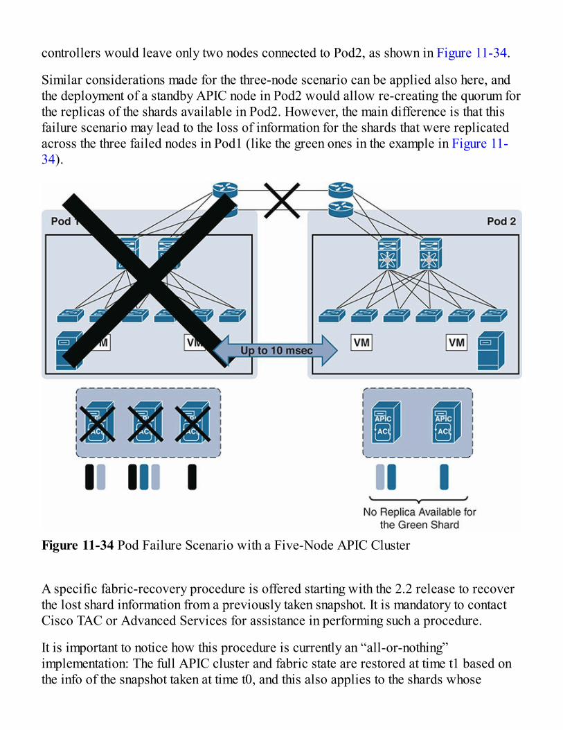
controllers would leave only two nodes connected to Pod2, as shown in Figure 11-34.
Similar considerations made for the three-node scenario can be applied also here, andthe deployment of a standby APIC node in Pod2 would allow re-creating the quorum forthe replicas of the shards available in Pod2. However, the main difference is that thisfailure scenario may lead to the loss of information for the shards that were replicatedacross the three failed nodes in Pod1 (like the green ones in the example in Figure 11-34).
Figure 11-34 Pod Failure Scenario with a Five-Node APIC Cluster
A specific fabric-recovery procedure is offered starting with the 2.2 release to recoverthe lost shard information from a previously taken snapshot. It is mandatory to contactCisco TAC or Advanced Services for assistance in performing such a procedure.
It is important to notice how this procedure is currently an “all-or-nothing”implementation: The full APIC cluster and fabric state are restored at time t1 based onthe info of the snapshot taken at time t0, and this also applies to the shards whose
||||||||||||||||||||
||||||||||||||||||||

information was still available in Pod2 (that is, the orange and blue shards in Figure 11-34). As a consequence, configuration changes (add/delete) for all the shards are lost forthe [t0, t1] window, together with statistics, historical fault records, and audit records.Active faults are instead evaluated again once the APIC cluster is reactivated after thecompletion of the fabric-recovery procedure.
Note An alternative approach could be deploying four APIC nodes in Pod1 andone in Pod2. This would not protect against the loss of info of some shards after thehard failure of Pod1 (and the consequent need to execute the fabric-recoveryprocedure); however, it would allow keeping all the shards in full read-write modein Pod1 when the two pods get isolated or after a hard failure of Pod2.
Based on the preceding considerations, the following recommendations can be made fordeploying a two-site Multi-Pod fabric:
When possible, deploy a three-node APIC cluster with two nodes in Pod1 and onenode in Pod2. Add a backup APIC node in Pod2 to handle the “full site failure”scenario.
If the scalability requirements force the deployment of a five-node cluster, wheneverpossible follow the guidelines depicted in Figure 11-35.
Figure 11-35 Deployment Guidance for a 5 Nodes APIC Cluster
Two things can be immediately noticed when looking at the table in this figure: First, thebasic rule of thumb is to avoid deploying three APIC nodes in the same pod, to preventthe potential loss of shard information previously discussed. This recommendation can
Technet24||||||||||||||||||||
||||||||||||||||||||

be followed when deploying three or more pods.
Second, a pod can be part of the Multi-Pod fabric even without having a locallyconnected APIC cluster. This would be the case when deploying six (or more) podsleveraging a five-node APIC cluster or when deploying four (or more) pods with athree-node APIC cluster.
Reducing the Impact of Configuration Errors withConfiguration ZonesThe deployment of a single APIC cluster managing all the pods connected to the sameACI Multi-Pod fabric greatly simplifies the operational aspects of the fabric (providinga single point of management and policy definition). As a consequence, and similar to asingle-pod ACI deployment, it is possible to make changes that apply to a very largenumber of leafs and ports, even belonging to separate pods. Although this is one of thegreat benefit of using ACI—because it makes it possible to manage a very largeinfrastructure with minimum configuration burden—it may also raises concerns that aspecific configuration mistake that involves many ports may have an impact across allthe deployed pods.
The first solution built in to the system to help reduce the chances of making suchmistakes is a button labeled Show Usage that’s provided next to each policyconfiguration. This provides system and infrastructure administrators with informationabout which elements are affected by the specific configuration change they are going tomake.
In addition to this, a new functionality has been introduced in the APIC to limit thespreading of configuration changes only to a subset of the leaf nodes deployed in thefabric. This functionality calls for the creation of “configuration zones,” where eachzone includes a specific subset of leaf nodes connected to the ACI fabric.
Using configuration zones lets you test the configuration changes on that subset of leafsand servers before applying them to the entire fabric. Configuration zoning is onlyapplied to changes made at the infrastructure level (that is, applied to policies in the“Infra” tenant). This is because a mistake in such a configuration would likely affect allthe other tenants deployed on the fabric.
The concept of configuration zones applies very nicely to an ACI Multi-Poddeployment, where each pod could be deployed as a separate zone (the APIC GUIallows you to directly perform this mapping between an entire pod and a zone).
||||||||||||||||||||
||||||||||||||||||||

Each zone can be in one of these “deployment” modes:
Disabled: Any update to a node that’s part of a disabled zone will be postponed untilthe zone deployment mode is changed or the node is removed from the zone.
Enabled: Any update to a node that’s part of an enabled zone will be immediatelysent. This is the default behavior. A node not part of any zone is equivalent to a nodethat’s part of a zone set to Enabled.
Changes to the infrastructure policies are immediately applied to nodes that aremembers of a deployment mode–enabled zone. These same changes are queued for thenodes that are members of a zone with the deployment mode disabled.
You could then verify that the configurations are working well on the nodes of the zonewith deployment mode enabled, and then change the deployment mode to “triggered” forthe zones with deployment mode disabled in order for these changes to be applied onthe leafs in this other zone.
Figure 11-36 Migration Scenarios: Adding Pods to an Existing ACI
Technet24||||||||||||||||||||
||||||||||||||||||||

Migration StrategiesMulti-Pod and the capabilities it provides comprise a very exciting proposition formost customers. As such, many customers have questions about supported architectureand migrations strategies. At press time, the architectures we discuss in this chapter arenot mutually exclusive, meaning that enterprises can take advantage of multiplearchitectures across the environment given that they are running supportedconfigurations and meet the hardware and software requirements. For instance, a sitemay start as a single fabric. Later the enterprise may choose to expand this fabric into aMulti-Pod architecture by using the original fabric as a seed pod, as shown in Figure11-36. In another scenario, an enterprise may have a stretch fabric implemented. Thestretch fabric is also viewed as a single fabric, and can be used as a seed fabric to builda Multi-Pod solution, as shown in Figure 11-36.
At a very high level, the following steps are required to migrate from a single or stretchfabric to a Multi-Pod design:
Step 1. Bring up and configure IPN according to requirements.
Step 2. Add connections and configure the original pod to IPN.
Step 3. Connect and auto-provision additional pods.
Step 4. Distribute APIC nodes across pods.
Finally, additional capabilities such as ACI WAN integration (shown in Figure 11-37)and Multi-Site (shown in Figure 11-38) can be used, optionally, to provide scalabilityand path optimization or policy extensibility/consistency, respectively.
||||||||||||||||||||
||||||||||||||||||||

Figure 11-37 Multi-Pod Integration with WAN
Technet24||||||||||||||||||||
||||||||||||||||||||

Figure 11-38 Multi-Pod + Multi-Site
||||||||||||||||||||
||||||||||||||||||||

Multi-Site ArchitectureACI Multi-Site is the easiest DCI solution in the industry. Communication betweenendpoints in separate sites (Layer 2 and/or Layer 3) is enabled simply by creating andpushing a contract between the endpoints’ EPGs. The evolution of the dual-fabricoption, ACI Multi-Site, has been developed to overcome some of the challenges of thedual-fabric design (see Figure 11-39); for example, the need for policy extensibility andconsistency across sites and the lack of a centralized tool for operating andtroubleshooting the multiple interconnected fabrics.
Figure 11-39 Traditional Dual-Fabric Design
With ACI Multi-Site, enterprises have the ability to manage multiple fabrics as regionsor availability zones. With the addition of licensing and an ACI Multi-Site controller,enterprises have complete control over the following:
Defining and provisioning policies across sites (scope of changes) Provisioning of Day 0 configuration to establish inter-site EVPN control plane
Technet24||||||||||||||||||||
||||||||||||||||||||

Data-plane VXLAN encapsulation across sites End-to-end policy enforcement Multi-Site controllers distributing cross-fabric configuration to multiple APICclusters
Monitoring the health-state of the different ACI sites Inter-site troubleshooting (post–3.0 release)
Note: All ACI leaf switches (NS, -E, -EX, -FX) support Multi-Site functionality.However, the spine line cards must be an EX line card (second generation ornewer) with a new FC-E fabric card. First-generation spines (including 9336PQ)are not supported.
The key component to the Multi-Site architecture is the Cisco ACI Multi-Site policymanager. It provides single- pane management, enabling you to monitor the health scorestate for all the interconnected sites. It also allows you to define, in a centralized place,all the inter-site policies that can then be pushed to the different APIC domains forrendering. It thus provides a high degree of control over when and where to push thosepolicies, hence allowing the tenant change separation that uniquely characterizes theCisco ACI Multi-Site architecture. Figure 11-40 shows the Multi-Site architecture withthe Multi-Site policy manager.
||||||||||||||||||||
||||||||||||||||||||

Figure 11-40 Multi-Site Overview
The Cisco ACI Multi-Site design uses the out-of-band (OOB) management network toconnect to the APIC clusters deployed in different sites. Multi-Site has the capability tosupport network connections between sites with support for a round trip time of 500msec to 1 second. It also provides northbound access through Representational StateTransfer (REST) APIs or the GUI (HTTPS), which allows you to manage the fulllifecycle of networking and tenant policies that need to be stretched across sites.
The Cisco ACI Multi-Site policy manager is not responsible for configuring Cisco ACIsite-local polices. This task still remains the responsibility of the APIC cluster at eachsite. The policy manager can import the relevant APIC cluster site-local policies andassociate them with stretched objects. For example, it can import site-locally definedVMM domains and associate them with stretched EPGs.
The Cisco ACI Multi-Site design is based on a microservices architecture in whichthree virtual machines are clustered together in an active-active fashion. At the Muti-Site feature release, Multi-Site clusters are packaged in a VMware vSphere virtualappliance, as shown in Figure 11-41.
Technet24||||||||||||||||||||
||||||||||||||||||||

Figure 11-41 Cisco ACI Multi-Site Cluster for the VMware vSphere Appliance
Internally, each virtual machine has a Docker daemon installed with Multi-Siteapplication services. Those services are managed and orchestrated by a Docker swarmthat load-balances all job transactions across all Multi-Site containers in concurrentactive-active fashion for high availability.
A stable data-plane connection must exist between the Cisco ACI Multi-Site clustervirtual machines when they are deployed over a WAN. The virtual machines in a CiscoACI Multi-Site cluster communicate with each other over a TCP connection, so if anydrops occur in the WAN, dropped packets will be retransmitted. Also, be sure toappropriately mark the Differentiated Services Code Point (DSCP) value of virtualmachine traffic in a VMware port group. The recommended approach is to mark theDSCP as Expedited Forwarding (EF).
The recommended connection bandwidth between virtual machines in a Cisco ACIMulti-Site cluster is from 300Mbps to 1Gbps. These numbers are based on internalstress testing while adding very large configurations (over maximum scale numbers) anddeleting them at high frequency.
||||||||||||||||||||
||||||||||||||||||||

APIC Versus Multi-Site Controller FunctionalitiesIt is important to note the different roles that the APICs will play in the infrastructureversus the Multi-Site controller. In short, the Multi-Site controller does not replace theAPIC. The APIC maintains its role as controller for a fabric. The Multi-Site controlleris responsible for provisioning and managing inter-site tenant and networking policies.The Multi-Site controller then granularly propagates those policies to the multiple APICclusters across the enterprise based on enterprise policy. Table 11-1 outlines the rolesof the APIC and Multi-Site controller.
Table 11-1 APIC Versus Multi-Site Controller Functionalities
APIC Multi-Site Controller
Role/Function Central point ofmanagement andconfiguration for the fabric.Responsible for all fabric-local functions such as thefollowing:
Fabric discovery andbring up
Fabric access policies Service graphs Domain creation (VMM,physical, and so on)
Provisioning and managingof “inter-site tenant andnetworking policies.”Does not replace butcomplements APIC.
Integrations with OtherDevices
Integration with third-partyservices.
Can import and mergeconfiguration from differentAPIC clusters.
Runtime Data Maintain runtime data(VTEP address, VNID,Class_ID, GIPo, and soon).
No runtime data, only aconfiguration repository.
Data Plane/ControlPlane
No participation in thefabric data plane andcontrol plane.
No participation in dataplane and control plane.
Troubleshooting/Visibility Single-fabric or Multi-Pod End-to-end visibility and
Technet24||||||||||||||||||||
||||||||||||||||||||

visibility andtroubleshooting.
troubleshooting.
Scope of Changes Within a Multi-Pod orsingle fabric.
Granularity to propagatepolicies to multiple APICclusters.
Now that we are familiar with the Multi-Site cluster and what its role is, the followingis a list of best practices for deploying a Multi-Site cluster:
Connect the Multi-Site cluster to the APICs using the OOB management network. The Multi-Site cluster should never be deployed within a Cisco ACI fabric that it ismanaging as a site. It should always be deployed outside the Cisco ACI fabric (forexample, connected to the OOB network). Otherwise, double failures can occur ifthe Multi-Site cluster fails or the Cisco ACI fabric fails.
Each Multi-Site virtual machine should have a routable IP address, and all threevirtual machines must be able to ping each other. This setup is required to form aDocker swarm cluster.
Note For more information on Docker, see the following link:https://www.docker.com/.
Deploy one Multi-Site virtual machine per ESXi host for high availability. Thevirtual machines will form a cluster among themselves through a Docker swarm.
The maximum RTT between the virtual machines in a cluster should be less than 150ms.
The maximum distance from a Multi-Site cluster to a Cisco ACI fabric site can be upto 1 second RTT.
A Multi-Site cluster uses the following ports for the internal control plane and dataplane, so the underlay network should always ensure that these ports are open (in thecase of an ACL configuration of a firewall deployment in the network): TCP port 2377 for cluster management communication TCP and UDP port 7946 for communication among nodes UDP port 4789 for overlay network traffic TCP port 443 for Multi-Site policy manager user interface (UI)
||||||||||||||||||||
||||||||||||||||||||

IP 50 Encapsulating Security Protocol (ESP) for encryption IPSec is used to encrypt all intra-Multi-Site cluster control-plane and data-planetraffic to provide security because the virtual machines can be placed up to 150 msRTT apart.
The minimum specifications for Multi-Site virtual machines are ESXi 5.5 or later,four vCPUs, 8GB of RAM, and a 5GB disk.
Note At press time, Multi-Site scalability numbers are eight sites, 100 leaf nodesper site, 2000 BDs, 2000 EPGs, and 2000 contracts. These numbers will increasewith future software versions.
Multi-Site Schema and TemplatesThe Multi-Site controller essentially becomes the controller of controllers in regard tomanaging policy across your Multi-Site environment. To manage these policies in ahierarchical manner, a new policy type called a schema was added to the object model.Schemas are the containers for single or multiple templates that are used for definingpolicies. Templates are the framework for defining and deploying the policies to thesites in a Multi-Site configuration. Figure 11-42 depicts this new policy model.
Technet24||||||||||||||||||||
||||||||||||||||||||

Figure 11-42 Framework for Cisco ACI Multi-Site Schema and Templates
Assuming the Multi-Site design is already up and running, an enterprise need only startcreating policies and associating them with sites. In-depth step-by-step information onhow to do this can be found in the white paper titled “Modeling an Application withCisco ACI Multi-Site Policy Manager” on the Cisco site(https://www.cisco.com/c/dam/en/us/solutions/collateral/data-center-virtualization/application-centric-infrastructure/white-paper-c11-739481.pdf).
A high-level overview of the steps for configuring a Multi-Site policy using the Multi-Site controller is provided here to give you an idea of the workflow. The steps are asfollows:
Step 1. Create a tenant.
Step 2. Associate the tenant with one or more sites and specify the security domain(this controls the objects a user can access or interact with).
||||||||||||||||||||
||||||||||||||||||||

Figure 11-43 shows the first two steps.
Figure 11-43 Adding a Tenant, Associated Sites, and Security Domains
Step 3. Add a schema.
Step 4. Create or rename the default template.
Step 5. Associate the template with a tenant.Figure 11-44 shows steps 4 and 5.
Figure 11-44 Associating a Template with a Tenant
Technet24||||||||||||||||||||
||||||||||||||||||||

Step 6. Associate the template to sites where it should be deployed (as shown inFigure 11-45).
Figure 11-45 Associating the Template with Sites
Step 7. Create an application profile.
Step 8. Create EPGs.
Step 9. Associate the EPGs with a domain.
Step 10. Define bridge domains and the following options (as shown in Figure 11-46):
L2 STRETCH: This flag indicates that the bridge domain should bestretched across both sites, which implies that the associated IP subnet10.10.1.0/24 will also be available in the two sites.
INTERSITE BUM TRAFFIC ALLOW: This flag indicates that flooding isenabled across the sites for Layer 2 broadcast, unknown unicast, andmulticast frames. This capability is required, for example, to allow livemigration of endpoints and to deploy inter-site application clusters. If thisflag was not set, the same bridge domain and associated IP subnet would stillbe deployed at the two sites (because the bridge domain is stretched), but thedeployment could handle only inter-site “cold” IP mobility scenarios (forexample, for disaster-recovery use cases).
||||||||||||||||||||
||||||||||||||||||||

OPTIMIZE WAN BANDWIDTH: This flag helps ensure association of aunique multicast group with this bridge domain. This feature optimizes theutilization of WAN bandwidth because it prevents flooding across a site’sbroadcast, unknown unicast, and multicast frames that define a subnet forBDs that are stretched across sites. If a BD is not stretched, configure it as“site local” by clicking the site and then configuring the BD.
Figure 11-46 Multi-Site Bridge Domain Configuration
Step 11. Define a VRF.
Step 12. Create a contract with the appropriate filters and with EPGs selected asconsumers and providers, as shown in Figure 11-47.
Technet24||||||||||||||||||||
||||||||||||||||||||

Figure 11-47 Multisite Contract Configuration
Step 13. Deploy the template to sites, as shown in Figure 11-48.
Now that we have examined Multi-Site schemas and templates, we will discussindividual use cases in the following section.
Figure 11-48 Deploy the Template to Sites
||||||||||||||||||||
||||||||||||||||||||

Multi-Site Use CasesMulti-Site will have the capabilities to address the following three main use cases, asillustrated in Figure 11-49:
1. L3 connectivity between sites and centralized management of policy2. IP mobility for disaster recovery (for example, “cold” VM migration)
3. Highly scalable active-active DCs (for example, “hot” VM migration)
In the sections that follow, we will explore each Multi-Site option and the use cases itsupports.
Stretched Bridge Domain with Layer 2 Broadcast Extension (Option 3)This is the most sought-after data center and Cisco ACI Multi-Site use case (active-active data centers), in which a tenant and VRF are stretched between sites. The EPGsin the VRF (with their bridge domains and subnets), as well as their provider andconsumer contracts, are also stretched between sites.
In this use case, Layer 2 broadcast flooding is enabled across fabrics. Unknown unicasttraffic is forwarded across sites leveraging the Head-End Replication (HER)capabilities of the spine nodes that replicate and send the frames to each remote fabricwhere the Layer 2 BD has been stretched, as illustrated in Figure 11-50.
Technet24||||||||||||||||||||
||||||||||||||||||||

Figure 11-49 Multi-Site Use Cases
Figure 11-50 Stretched Bridge Domain with Layer 2 Broadcast Extension
The specific use cases this design addresses are as follows:
The same application hierarchy is deployed on all sites with common policies. Thisallows for seamlessly deploying workloads belonging to the various EPGs acrossdifferent fabrics and governing their communication with common and consistentpolicies.
Layer 2 clustering. Live VM migration. Active-active high availability between the sites. Using service graphs to push shared applications between sites is not supported.
Technet24||||||||||||||||||||
||||||||||||||||||||

Stretched Bridge Domain with No Layer 2 Broadcast Extension (Option 2)This Cisco ACI Multi-Site use case (active-passive/disaster recovery) is similar to thefirst use case where a tenant, VRF, and their EPGs (with their bridge domains andsubnets) are stretched between sites, as shown in Figure 11-51.
However, in this case, Layer 2 broadcast flooding is localized at each site. Layer 2broadcast, unknown unicast, and multicast (BUM) traffic is not forwarded across sitesover replicated VXLAN tunnels.
Figure 11-51 Stretched Bridge Domain with No Layer 2 Broadcast Extension
Here are the specific use cases this design addresses:
Control plane overhead is reduced by keeping Layer 2 flooding local. Inter-site IP mobility for disaster recovery. “Cold” VM migration. Using service graphs to push shared applications between sites is not supported.
||||||||||||||||||||
||||||||||||||||||||

Stretched EPG Across Sites (Option 1.1)This Cisco ACI Multi-Site use case provides endpoint groups (EPGs) stretched acrossmultiple sites. Stretched EPG is defined as an endpoint group that expands acrossmultiple sites where the underlying networking, site local, and bridge domain can bedistinct, as shown in Figure 11-52.
This use case allows Layer 3 forwarding to be used among all sites.
Stretched VRF with Inter-Site Contracts (Option 1.2)This Multi-Site use case provides inter-site communication between endpointsconnected to different bridge domains (BDs) that are part of the same stretched VRF, asillustrated in Figure 11-53. VRF stretching is a convenient way to manage EPGs acrosssites (and the contracts between them).
Technet24||||||||||||||||||||
||||||||||||||||||||

Figure 11-52 Stretched EPG Across Sites
Figure 11-53 Stretched VRF with Inter-Site Contracts
In this figure, the App-EPGs provide the C1 and C2 contracts across the sites, and theWeb-EPGs consume them across the sites.
This use case has the following benefits:
The tenant and VRF are stretched across sites, but EPGs and their policies(including subnets) are locally defined.
Because the VRF is stretched between sites, contracts govern cross-sitecommunication between the EPGs. Contracts can be consistently provided andconsumed within a site or across sites.
Traffic is routed within and between sites (with local subnets) and static routingbetween sites is supported.
||||||||||||||||||||
||||||||||||||||||||

Separate profiles are used to define and push local and stretched objects. No Layer 2 stretching and local Layer 2 broadcast domains. “Cold” VM migration, without the capability of preserving the IP address of themigrated endpoints.
Using service graphs to push shared applications between sites is not supported.
Shared Services with Stretched Provider EPGIn this use case, the Provider EPGs in one group of sites offer shared services, and theEPGs in another group of sites consume the services. All sites have local EPGs andbridge domains, as illustrated in Figure 11-54.
As Figure 11-54 shows, Site 4 and Site 5 (with BigData-EPG, in Tenant BigData/VRFBigData) provide shared data services, and the EPGs in Site 1 to Site 3 (in Tenant1/VRF 1) consume the services.
In the shared services use case of Multi-Site, at the VRF boundary routes are leakedbetween VRFs for routing connectivity and by importing contracts across sites.
This use case has the following benefits:
Shared services enable communications across VRFs and tenants while preservingthe isolation and security policies of the tenants.
A shared service is supported only with non-overlapping and non-duplicate subnets. Each group of sites has a different tenant, VRF, and one or more EPGs stretchedacross it.
Site groups can be configured to use Layer 2 broadcast extensions or to localizeLayer 2 flooding.
Stretched EPGs share the same bridge domain, but the EPGs have subnets that areconfigured under the EPG, not under the bridge domain.
The provider contract must be set to global scope. VRF route leaking enables communication across the VRFs. Using service graphs to push shared applications between sites is not supported.
Technet24||||||||||||||||||||
||||||||||||||||||||

Figure 11-54 Shared Services with Stretched Provider EPG
Multi-Site and L3 Out ConsiderationsSimilar to a single-fabric deployment, ACI Multi-Site can connect to an external Layer3 domain with both traditional L3 Out connections defined on the border leaf nodes andEVPN WAN integration. At press time, the only supported configuration for endpointswishing to communicate with external networks over a Layer 3 outbound domain is viaa L3 Out that is local to the fabric the endpoint is connected to, as shown in Figure 11-55.
||||||||||||||||||||
||||||||||||||||||||

Technet24||||||||||||||||||||
||||||||||||||||||||

Figure 11-55 Supported and Non-supported Uses of L3 Out in a Multi-Site Deployment
Note: This requirement applies to both traditional L3 Out configurations and WANintegration.
In this design, traffic has the opportunity to enter the fabric at Site 1 and be sent to aresource at Site 2, where it is required to exit locally. If this traffic will pass through afirewall, it will normally be dropped due to its stateful nature. Enterprises need to payattention to the creation of asymmetric traffic paths when stateful devices are being usedin their deployment. Finally, as you’ll remember from earlier chapters, some devicesconnect and share information with the fabric over a L3 Out connection. Enterprisesneed to consider if network devices (mainframe, voice gateways, and so on) areconnected to the ACI fabric via L3 Out instances that must be accessible across sites.These devices may have to be deployed in a more distributed manner for the traffic tobe able to use a local L3 Out to communicate with them.
Layer 3 Multicast Deployment OptionsEarlier chapters examined the multicast support options for non-Multi-Site designs. Atpress time, there is currently no support for native Layer 3 multicast with ACI Multi-Site. The currently supported options, depicted in Figure 11-56, are as follows:
Source(s) and receiver(s) part of non-stretched BDs and connected to the same site(top left)
Source(s) part of a non-stretched BD and receiver(s) outside the fabric (bottom left) Source(s) outside the fabric and receiver(s) connected to a non-stretched BD (rightside)
Note Layer 3 multicast configuration is performed at the local APIC level and noton the ACI Multi-Site policy manager.
It is also worth noting, as shown in Figure 11-57, that the source(s) in Site 1 cannot sendan L3 multicast stream to receiver(s) in a remote site. This is planned to be supported in
||||||||||||||||||||
||||||||||||||||||||

a later release.
Technet24||||||||||||||||||||
||||||||||||||||||||

Figure 11-56 Supported Multicast Designs with Multi-Site
Figure 11-57 Unsupported Multi-Site Design with Multicast
Migration of Cisco ACI Fabric to Cisco ACI Multi-SiteIn this section, we will explore a common Cisco ACI Multi-Site use case in which atenant is migrated to or imported from Cisco ACI fabric to Cisco ACI Multi-Site.
This use case is targeted for brownfield-to-greenfield and greenfield-to-greenfieldtypes of deployments. The brownfield-to-brownfield use case is only supported in thisrelease if both Cisco APIC sites are deployed with the same configuration. Otherbrownfield-to-brownfield use cases will be deployed in a future Cisco ACI Multi-Siterelease.
The top two examples shown in Figure 11-58 for brownfield configurations reflect twoscenarios that are considered for deployments:
A single pod ACI fabric is in place already. You can add another site in a Multi-Siteconfiguration.
Two ACI fabrics are in place already (each fabric is configured as a single pod), theobjects (tenants, VRFs, and EPGs) across sites are initially defined with identicalnames and policies, and they are connected by leveraging a traditional L2/L3 DCI
Technet24||||||||||||||||||||
||||||||||||||||||||

solution. You can convert this configuration to Multi-Site as explained in thefollowing configuration diagram.
Note Cisco ACI Multi-Pod migration to Cisco ACI Multi-Site shown as the thirdoption in Figure 11-58 will be supported in a future Cisco ACI Multi-Site release.
Figure 11-58 illustrates the enterprise migration path from existing architectures toMulti-Site architectures.
Figure 11-58 Migration Paths
||||||||||||||||||||
||||||||||||||||||||

SummaryEnterprises can be confident that ACI has an architecture that meets their businessrequirements and data center needs. ACI started with a single fabric with version 1.0.With version 1.1, ACI had the ability to create geographically stretched single fabrics.To address the concerns about extending a single network fault domain across the entirestretched-fabric topology, Cisco ACI Release 2.0 introduced the Cisco ACI Multi-Podarchitecture. The need for complete isolation (at both the network and tenant changedomain levels) across separate Cisco ACI networks led to the Cisco ACI Multi-Sitearchitecture, introduced in Cisco ACI Release 3.0.
No matter which design you choose, you will find that ACI is the easiest-to-deploy, themost secure, and the most operationally efficient data center fabric there is, regardlessof what type of workloads you support—virtual or physical.
Technet24||||||||||||||||||||
||||||||||||||||||||

Troubleshooting and Monitoring
In this chapter, you will learn the following:
Use of the Cisco ACI graphical user interface (GUI) and command-line interface(CLI) in order to troubleshoot frequent issues, such as connectivity problems andaccess control lists (ACLs)
New troubleshooting tools available in Cisco ACI that did not exist previously, suchas atomic counters, the Endpoint Tracker, and the Traffic Map
Improved ways of leveraging existing technologies such as Switched Port Analyzer(SPAN) and traffic counters
How to use the Troubleshooting Wizard in Cisco ACI Integration between Cisco ACI and network monitoring tools using both the SimpleNetwork Management Protocol (SNMP) and the REST API
Designing and implementing a solid network are a big part of the job of a networkadministrator; however, after you build the network, it needs to be monitored, andeventual problems need to be fixed as quickly as possible. The more robust a networkis, the fewer problems that appear later. Cisco ACI takes care of part of that job byincorporating state-of-the-art designs and technologies that reduce and minimizeproblems. Here are some examples:
An IP-based fabric is much more robust and flexible than networks that rely onSpanning Tree.
ACI by default preserves network resources, deploying network constructs onlywhere required.
The spine-leaf architecture can be easily scaled in case bottlenecks are identified.
Nevertheless, problems will appear sooner or later, no matter how robust the networkdesign may be. Previous chapters have described how those problems can be easilyidentified in the GUI, along with their tenant and application impact, using ACI’s
Technet24||||||||||||||||||||
||||||||||||||||||||

integrated health scores and other methods. This chapter focuses on how to monitor thenetwork and how to troubleshoot existing problems once they have been identified.
You Have a Poor Health Score. Now What?Chapter 7, “How Life Is Different with ACI,” described how the different options inCisco ACI provide a quick view of the state of the network—either of the logicalobjects (viewed via dashboards) or of the physical ones (shown in the Fabric tab of theGUI). Hopefully everything is at 100% health, but eventually problems will arise andsome health score will go down.
The standard way in which you observe that the network is not behaving properly is byrealizing (or getting alerted) that a certain health score has dropped below 100%. Asprevious chapters have shown, this approach is more effective than traditional networkmonitoring, because it immediately provides information about the criticality of thenetwork issue, in terms of which tenant and application are impacted.
Obviously, as described in Chapter 9, “Multi-Tenancy,” the more granular your tenantand application structure is, the more accurately the health scores will describe theimpact of a certain fault. For example, if you have all your network objects and endpointgroups (EPGs) under the common tenant, the fact that this tenant’s health goes down willnot tell you a lot about the impacted objects. However, if you have structured yournetwork objects in multiple tenants and applications (as Chapter 9 describes with theexample of a tenant for a vSphere infrastructure), Cisco ACI dashboards will show youexactly which tenant is impacted in case of a network outage. This is extremely usefulwhen you’re prioritizing troubleshooting activities because the network operators willhave the required information needed to focus on the issue impacting the most criticalapplications.
Another area of the GUI you want to be checking on regularly is the overall Faultspanel. As described in Chapter 7, you can see the whole list of issues present in yournetwork in the Faults panel, so it is a very good place to start when troubleshooting aproblem. If you consult this view, as shown as example in Figure 12-1, you can quicklyverify the overall status of the network, and whether there are any critical faults thatmight be impacting the proper functioning of the fabric. Actually, it is good practice tocheck the Faults panel every now and then, especially after performing configurations.
||||||||||||||||||||
||||||||||||||||||||

Figure 12-1 Cisco ACI Faults Panel Showing the Existing Faults in a Fabric
NX-OS CLINetwork administrators have traditionally relied heavily on the command-line interface(CLI) of network devices for troubleshooting. Although most information is available inthe GUI, Cisco ACI offers a CLI for those specialists who prefer it. Whetheradministrators use the text-based command line or the GUI depends on personalpreference, as most information is available both ways.
Cisco ACI’s command line shares similarities with other Cisco networking products,including the overall look and feel and most commands. However, at the same time, it isin some aspects different. The main difference is that Cisco ACI’s CLI is centralized—network professionals no longer need to connect to every single device in order toextract information out of the network.
The CLI is accessed on the Application Policy Infrastructure Controller (APIC)—anSSH session needs to be established to the APIC’s IP address, and the familiar CiscoCLI prompt will be available. Once you connect to the APIC, you can gather interestinginformation from a central CLI, without having to open multiple SSH windows (as was
Technet24||||||||||||||||||||
||||||||||||||||||||

the case in legacy, device-centric networks).
For example, you might want to find out information about a certain endpoint. This iswhere the show endpoints command comes into play, where you can see details such asits IP address, its MAC address, the switch and port where it is connected, and to whichtenant, application, and EPG it belongs, as demonstrated in Example 12-1 (note thatyour output might be different because the following examples have been modified sothat they fit the page’s width).
Gone are the days when network administrators need to open multiple windows just tofind out where a certain server is connected or to troubleshoot network issues.
You can verify the object model or the health scores for different objects asdemonstrated in Example 12-2, which shows how to get the health of a tenant, even ifthat tenant is physically deployed across multiple switches.
Example 12-1 Finding Out Where a Specific Host Is Attached to the FabricClick here to view code image
apic# show endpoints ip 192.168.20.11Dynamic Endpoints:Tenant : Pod2Application : Pod2AEPg : EPG1 End Point MAC IP Address Node Interface Encap----------------- ------------------------- ------ --------------- --------00:50:56:AC:D1:71 192.168.20.11 202 eth102/1/1 vlan-12Total Dynamic Endpoints: 1Total Static Endpoints: 0apic#
Example 12-2 Verifying Tenants’ Health ScoresClick here to view code image
apic# show health tenant Score Change(%) UpdateTS Dn
||||||||||||||||||||
||||||||||||||||||||

----- ----- ------------------- ------------------------------ 100 0 2016-09-19T15:09:29 uni/tn-common/health .324+02:00 100 0 2016-09-19T15:09:29 uni/tn-SiriusCyber/health .328+02:00 100 0 2016-09-19T15:09:29 uni/tn-VMware/health .319+02:00 100 0 2016-09-19T15:01:39 uni/tn-CONTIV-default/health .210+02:00 99 0 2016-09-19T15:09:29 uni/tn-infra/health .324+02:00 100 0 2016-09-19T15:10:05 uni/tn-Docker/health .365+02:00 100 0 2016-09-19T15:09:29 uni/tn-LeisureMech3/health .327+02:00 100 0 2016-09-19T15:09:29 uni/tn-Pod1/health .326+02:00 100 0 2016-09-19T15:10:05 uni/tn-ASA_admin/health .366+02:00
Chapter 13, “ACI Programmability,” explains in more detail the structure and namingconventions of the internal objects in Cisco ACI. For the sake of understanding thisexample, you need to know that ACI objects get an internal name that is prefixed with astring denoting the class to which those objects belong. For example, the tenant“common” is actually called “tn-common” internally, because the prefix “tn-” meansthat this object is a tenant. Chapter 13 explains how to find out the string prefix thatidentifies each object class. For the rest of this chapter, though, you can safely ignorethose prefixes.
You can even have a look at the complete configuration, as you would do with any NX-OS switch, using the show running-configuration command. As in NX-OS, you canhave a look at the full running configuration, or just at a part of it, such as theconfiguration corresponding to a specific tenant, as demonstrated in Example 12-3.
Example 12-3 Displaying a Tenant’s ConfigurationClick here to view code image
apic# show running-config tenant Pod1
Technet24||||||||||||||||||||
||||||||||||||||||||

# Command: show running-config tenant Pod1# Time: Mon Sep 19 15:13:12 2016 tenant Pod1 access-list Telnet match raw telnet dFromPort 23 dToPort 23 etherT ip prot 6 stateful yes exit contract EPG1-services scope exportable export to tenant Pod2 as Pod1-EPG1 subject EPG1-services access-group default both exit exit contract EPG2-services subject EPG2-services access-group Telnet both access-group icmp both log exit exit vrf context Pod1-PN exit l3out ACI-ISR vrf member Pod1-PN exit bridge-domain Pod1-BD vrf member Pod1-PN exit application Pod1 epg EPG1 bridge-domain member Pod1-BD contract consumer EPG2-services contract provider EPG1-services vmware-domain member ACI-vCenter-VDS deploy immediate exit
exit epg EPG2 bridge-domain member Pod1-BD contract provider EPG2-services exit exit
||||||||||||||||||||
||||||||||||||||||||

external-l3 epg Pod1-L3-NW l3out ACI-ISR vrf member Pod1-PN match ip 0.0.0.0/0 contract consumer EPG1-services
The Cisco ACI CLI offers some interesting ACI-specific tools. One of these tools is theacidiag command, which is demonstrated in Example 12-4. This tool can be used forvery specific troubleshooting purposes but is outside the scope of this book. One of itsmost interesting aspects is that it can generate a token with which Cisco TechnicalAssistance Center (TAC) produces a root password used for logging in to an APIC asthe root user. Needless to say, this is not an operation you would perform every day, butprobably something that Cisco specialists would help you with in case your ACIenvironment has some kind of trouble.
Example 12-4 acidiag Command OutputClick here to view code image
apic# acidiagusage: acidiag [-h] [-v]{preservelogs,bootother,rvreadle,avread,touch,installer,start,crashsuspecttracker,
reboot,dmestack,platform,version,verifyapic,run,stop,dmecore,fnvread,restart,
bootcurr,bond0test,rvread,fnvreadex,validateimage,validatenginxconf,linkflap,
dbgtoken} ...apic# acidiag dbgtoken0WDHFZPPDSQZ
There are many other examples of useful CLI commands in Cisco ACI, but we will stopwith acidiag because the main purpose of this section isn’t to list Cisco ACI commandsbut to describe its main architectural difference as compared to legacy networks.
Technet24||||||||||||||||||||
||||||||||||||||||||

Connecting to the Leaf SwitchesIf you want to run certain commands in one or more leaf switches, you can do so fromthe ACI CLI, instead of connecting to each individual leaf. You do this by prefixing thecommand with the word fabric and then the leaf or leaf switches where you want to runit.
For example, if you want to have a look at the traffic counters on the port where theserver mentioned in the preceding examples is connected, you could use the commandshow interface prefixed by fabric 202 (because, as you saw, the server is connected toleaf 202), as demonstrated in Example 12-5.
Example 12-5 Displaying Traffic Counters on a Specific Port from the ACI CentralizedCLIClick here to view code image
apic# fabric 202 show interface ethernet 102/1/1---------------------------------------------------------------- Node 202 (Leaf202)----------------------------------------------------------------Ethernet102/1/1 is upadmin state is up, Dedicated Interface Port description is ESX-01 Hardware: 100/1000/auto Ethernet, address: f029.296a.5682 (bia f029.296a.5682) MTU 9000 bytes, BW 1000000 Kbit, DLY 1 usec reliability 255/255, txload 1/255, rxload 1/255 Encapsulation ARPA, medium is broadcast Port mode is trunk full-duplex, 1000 Mb/s FEC (forward-error-correction) : disable-fec Beacon is turned off Auto-Negotiation is turned off Input flow-control is off, output flow-control is off Auto-mdix is turned off Switchport monitor is off EtherType is 0x8100 EEE (efficient-ethernet) : n/a Last link flapped 10w75d Last clearing of “show interface” counters 10w75d
||||||||||||||||||||
||||||||||||||||||||

1 interface resets 30 seconds input rate 3792 bits/sec, 6 packets/sec 30 seconds output rate 6800 bits/sec, 11 packets/sec Load-Interval #2: 5 minute (300 seconds) input rate 3792 bps, 5 pps; output rate 7160 bps, 12 pps RX 4360376993 unicast packets 108340 multicast packets 13000840 broadcast packets 4373486173 input packets 10439463704 bytes 2084 jumbo packets 0 storm suppression bytes 0 runts 2084 giants 0 CRC 0 no buffer 0 input error 0 short frame 0 overrun 0 underrun 0 ignored 0 watchdog 0 bad etype drop 0 bad proto drop 0 if down drop 0 input with dribble 0 input discard 0 Rx pause TX 4328569988 unicast packets 4505014 multicast packets 75985490 broadcast packets 4409060492 output packets 13099256068 bytes 507 jumbo packets 0 output error 0 collision 0 deferred 0 late collision 0 lost carrier 0 no carrier 0 babble 0 output discard 0 Tx pause
Alternatively, you could verify which interfaces exist in the leaf altogether with thecommand show ip interface brief, as demonstrated in Example 12-6. Just rememberthat ACI is a multi-VRF network, so you need to specify which VRF you are interestedin (or just ask for all of them).
Example 12-6 Verifying IP Addresses Configured in a Leaf from the ACI CentralizedCLIClick here to view code image
apic# fabric 203 show ip int brief vrf all---------------------------------------------------------------- Node 203 (Leaf203)----------------------------------------------------------------IP Interface Status for VRF “overlay-1”(12)Interface Address Interface Status
Technet24||||||||||||||||||||
||||||||||||||||||||

eth1/49 unassigned protocol-up/link-up/admin-upeth1/49.1 unnumbered protocol-up/link-up/admin-up (lo0)eth1/50 unassigned protocol-down/link-down/admin-upeth1/51 unassigned protocol-down/link-down/admin-upeth1/52 unassigned protocol-down/link-down/admin-upeth1/53 unassigned protocol-down/link-down/admin-upeth1/54 unassigned protocol-down/link-down/admin-upvlan11 10.0.0.30/27 protocol-up/link-up/admin-uplo0 10.0.96.64/32 protocol-up/link-up/admin-uplo1023 10.0.0.32/32 protocol-up/link-up/admin-upIP Interface Status for VRF “black-hole”(3)Interface Address Interface StatusIP Interface Status for VRF “management”(2)Interface Address Interface Statusmgmt0 192.168.0.53/24 protocol-up/link-up/admin-upIP Interface Status for VRF “SiriusCyber:Sirius-external”(4)Interface Address Interface Statusvlan6 192.168.7.25/29 protocol-up/link-up/admin-uplo3 192.168.7.204/32 protocol-up/link-up/admin-up
The CLI local to every leaf is very similar to standard NX-OS. As the previousexample demonstrates, you can run local leaf commands directly from the APIC with thefabric prefix, or you can connect to an individual leaf using the ssh command in theAPIC CLI, followed by the name or the number of the leaf to which you want to connect.The password is the same as for the APIC. If you don’t remember the name of a certainleaf, you can easily have a look at the switch names with show version, as demonstratedin Example 12-7.
||||||||||||||||||||
||||||||||||||||||||

Example 12-7 Displaying Versioning Information for All ACI ComponentsClick here to view code image
apic# show version Role Id Name Version ---------- ---------- ------------------------ -------------------- controller 1 apic 2.0(1m) leaf 201 Leaf201 n9000-12.0(1m) leaf 202 Leaf202 n9000-12.0(1m) leaf 203 Leaf203 n9000-12.0(1m) spine 301 Spine301 n9000-12.0(1m)apic# ssh Leaf201Password:Last login: Tue Sep 13 14:50:24 2016 from 192.168.0.50Cisco Nexus Operating System (NX-OS) SoftwareTAC support: http://www.cisco.com/tacCopyright (c) 2002-2016, Cisco Systems, Inc. All rights reserved.The copyrights to certain works contained in this software areowned by other third parties and used and distributed underlicense. Certain components of this software are licensed underthe GNU General Public License (GPL) version 2.0 or the GNULesser General Public License (LGPL) Version 2.1. A copy of eachsuch license is available athttp://www.opensource.org/licenses/gpl-2.0.php andhttp://www.opensource.org/licenses/lgpl-2.1.phpLeaf201#
Again, the point of this section is not to create a command reference for Cisco ACI’sCLI, but to help you understand how to use different commands relevant to differenttroubleshooting activities, and to demonstrate how the Cisco ACI CLI gives youinformation about the whole network from a single spot.
Technet24||||||||||||||||||||
||||||||||||||||||||

Linux CommandsAs you probably know, most network operative systems have Linux as the underlyingOS, and Cisco ACI is no exception. Both images on the controller and the switches arebased on Linux, and Cisco has made this Linux OS available for the network admin. Youonly need to type those commands from the standard ACI CLI, when you are connectedto either an APIC or a switch, as demonstrated in Example 12-8.
Example 12-8 Linux commands in the ACI CLIClick here to view code image
apic# uname -aLinux apic 3.4.49.0.1insieme-20 #1 SMP Thu Jun 2 21:39:24 PDT 2016 x86_64 x86_64 x86_64 GNU/Linux
You can use SSH to connect to other components of ACI, such as leaf and spineswitches, in case you need information that cannot be retrieved over the centralizedCisco ACI CLI, as Example 12-9 shows.
Example 12-9 Connecting to a Leaf in Order to Run a Command on the Switch ItselfClick here to view code image
apic# ssh Leaf201[...]Leaf201# uname -aLinux Leaf201 3.4.10.0.0insieme-0 #1 SMP Mon Aug 1 16:18:10 PDT 2016 x86_64 GNU/ Linux
Coming back to the APIC, let’s look at some interesting operations you can performusing Linux commands, if you know your way. For example, let’s have a look at storageutilization in the controller, as demonstrated in Example 12-10.
Example 12-10 Displaying Controller Storage UtilizationClick here to view code image
||||||||||||||||||||
||||||||||||||||||||

apic# df -hFilesystem Size Used Avail Use% Mounted on/dev/dm-1 36G 14G 21G 40% /tmpfs 4.0G 203M 3.9G 5% /dev/shmtmpfs 32G 4.0K 32G 1% /tmp/dev/mapper/vg_ifc0_ssd-data 36G 14G 21G 40% /data/dev/mapper/vg_ifc0-firmware 36G 13G 21G 38% /firmware/dev/mapper/vg_ifc0-data2 180G 2.3G 168G 2% /data2apic#
Alternatively, you can look at the different IP addresses in the controller (out-of-band,in-band, infrastructure, and so on) with well-known Linux commands such as ifconfigand ip addr. Example 12-11 shows the filtered output of ifconfig.
Example 12-11 Displaying Controller IP AddressesClick here to view code image
apic# ifconfig -a | grep addrbond0 Link encap:Ethernet HWaddr F4:4E:05:C0:15:4B inet6 addr: fe80::f64e:5ff:fec0:154b/64 Scope:Linkbond0.1019 Link encap:Ethernet HWaddr F4:4E:05:C0:15:4B inet addr:10.13.76.12 Bcast:10.13.76.255 Mask:255.255.255.0 inet6 addr: fe80::f64e:5ff:fec0:154b/64 Scope:Linkbond0.4093 Link encap:Ethernet HWaddr F4:4E:05:C0:15:4B inet addr:10.0.0.1 Bcast:10.0.0.1 Mask:255.255.255.255 inet6 addr: fe80::f64e:5ff:fec0:154b/64 Scope:Link
[...]oobmgmt Link encap:Ethernet HWaddr F0:7F:06:45:5A:94 inet addr:192.168.0.50 Bcast:192.168.0.255 Mask:255.255.255.0 inet6 addr: fe80::f27f:6ff:fe45:5a94/64 Scope:Link[...]
As you’ve probably noticed, you are logged in as admin, not as root (root privilege is
Technet24||||||||||||||||||||
||||||||||||||||||||

protected in Cisco ACI and is normally not needed). However, in certain exceptionalsituations, root access might be required. In this unlikely situation, Cisco TechnicalAssistance Center can generate root passwords for your APICs.
Mapping Local Objects to Global ObjectsCisco ACI is a policy-based system: The APIC tells the switches that they shouldperform a certain operation, but it does not tell them how to do it. You could comparethis to an airport control tower, which informs airplane pilots about the next action theyneed to take (approach the runway, maintain a holding pattern until a slot becomesavailable, fly at a certain altitude, and so on). However, the control tower will nevertell a pilot how to perform these tasks because that is the pilot’s job. The pilot knowshow to operate the plane, and they are not expecting the tower to tell them how to dotheir job.
Similarly, the APIC will instruct the switches to perform certain tasks, such as creatinga bridge domain (BD) or an EPG, but it will not tell them how to do so. As aconsequence, there might be some discrepancies in the way each individual switchdecides to implement a task. Therefore, one of the first steps you should take whentroubleshooting a certain object is to determine which IDs were locally assigned in eachindividual switch to the objects that the APIC instructed them to create.
The switches in an ACI fabric not only decide how to create objects but also whetherthey should be created at all. As Chapter 7 explained in depth, the overall scalability ofa spine-leaf fabric design depends on the resources of the leaf switches as well as howefficiently they are used, because most functionality is implemented there. As describedin that chapter, in Cisco ACI each leaf switch can decide whether or not to dedicatehardware resources for a certain configuration. For example, if there is no endpointbelonging to a certain tenant connected to a particular switch, programming that switchhardware with the tenant information would be a waste of resources.
In this dynamic environment, where network constructs are dynamically created andtorn down depending on what is needed, using a level of indirection for those objects’namespaces can be extremely useful. Indirection is a common resource used in computersystems whereby you refer to something, not by its real name, but by an alias to increasethe overall flexibility.
Do not worry if the previous paragraphs do not make a lot of sense just yet; thefollowing sections illustrate this indirection concept with two examples: VLAN IDs andport channels.
||||||||||||||||||||
||||||||||||||||||||

VLAN IDsIn order to create a bridge domain or an EPG, switches need to define a VLAN ID toimplement it in hardware, since switching Application Specific Integrated Circuits(ASICs) still deal in VLANs, not in bridge domains or EPGs. Leaf switches decidewhich VLAN ID to assign to each bridge domain and each EPG individually. Therefore,the VLAN IDs allocated to bridge domains and EPGs will most likely be differentacross the various leaf switches.
But now we come across an interesting problem: Say that APIC has instructed the leafswitches to create a certain bridge domain called “Web,” and the switch has picked upVLAN 5 to internally represent that EPG, for example. And right after that, the networkadministrator creates a static binding in another EPG in a BD called “Database” thatexpects packets tagged with VLAN 5 coming from a certain interface.
This would result in erroneous behavior because the switch would immediately put allthose packets into the BD “Web” instead of in “Database.” Cisco ACI resolves thisproblem very elegantly, by using two different VLAN namespaces: an internal namespace and an external namespace.
An approximate comparison would be your phone’s address book. When you want tocall somebody, you look for their name and press dial. Obviously, the phone willinternally translate the name to the number and then will place the call. The interestingthing here is the existence of two namespaces: the one you interact with, containing yourcontacts’ names, and the one used internally by the telephone to actually establish theconnection with the actual phone numbers.
In Cisco ACI, there is an external VLAN namespace for the VLANs you haveconfigured (similar to the contacts’ names in your phone), but there is also an internalVLAN namespace for the VLAN numbers that the switch uses internally (your contacts’phone numbers).
Now let’s come back to our example. As you saw, the Web BD was mapped to theinternal VLAN 5, and a static binding was configured on another EPG (Database) usingVLAN 5. The latter is an external VLAN. Both are VLAN 5, but in differentnamespaces. The obvious conclusion is that to prevent conflicts, in this case, the ACIleaf switch will associate the external VLAN 5 with an internal VLAN different fromVLAN 5 (otherwise, there would be a collision in the internal VLAN namespace).
One of the corollaries of the existence of two VLAN namespaces is that the internalVLAN IDs are locally significant to each leaf switch. Therefore, commands that refer tothe internal VLAN namespace will only work in single leaf switches.
Technet24||||||||||||||||||||
||||||||||||||||||||

That’s enough theory. Let’s look at some output examples. The first thing to look at iswhich VLAN IDs have been allocated to EPGs and bridge domains. Note that normallyyou don’t have a one-to-one relationship between EPGs and BDs, so each one of theseobjects will receive a dedicated and unique VLAN ID. This is the reason why thedefault scalability of the ACI leaf switch is the sum of EPGs and BDs (3500 at presstime).
Let’s have a look at what a bridge domain and an EPG look like from an APIC’sperspective, as demonstrated in Example 12-12. Notice how no VLAN ID is shown,because the VLAN ID assigned to each BD and to each EPG is locally significant toeach leaf switch (in other words, it belongs to the internal VLAN namespace).
Example 12-12 Showing Information Related to a Bridge Domain (No VLANInformation Is Displayed)Click here to view code image
apic# show bridge-domain Web Tenant Interface MAC Address MTU VRF Options---------- ---------- ------------------ -------- ----------- ---------------------- MyTenant Web 00:22:BD:F8:19:FF inherit default Multi Destination: bd-flood L2 Unknown Unicast: proxy L3 Unknown Multicast: flood Unicast Routing: yes ARP Flooding: no PIM Enabled: no
||||||||||||||||||||
||||||||||||||||||||

BD Type: regularapic# show epg Web Tenant Application AEPg Consumed Contracts Provided Contracts ---------- ---------- ------- ------------------ -------------------- MyTenant MyApp Web DB-Services Web-Services
However, by running a command localized to a specific leaf switch, you can actuallycheck whether the bridge domain or EPG has been deployed, and which internal VLANshave been chosen, as Example 12-13 shows. Remember that EPGs and bridge domainswill be deployed in a switch only when there are existing endpoints in that switch, notbefore.
Example 12-13 Displaying Internal VLANs in Specific Leaf SwitchesClick here to view code image
apic# fabric 201 show vlan extended---------------------------------------------------------------- Node 201 (Leaf201)---------------------------------------------------------------- VLAN Name Status Ports ---- -------------------------------- --------- -------------------------------[...] 5 MyTenant:Web-BD active Eth1/3, Eth1/4, Eth1/5, Eth101/1/1, Eth101/1/4, Po2[...] 74 MyTenant:MyApp:Web active Eth101/1/1, Eth101/1/4
If you issue the fabric 201 show vlan extended command in a different leaf switch, theVLANs would typically be different, because those VLANs belong to the VLANnamespace internal to each individual leaf switch.
Technet24||||||||||||||||||||
||||||||||||||||||||

Legacy ModeYou can define EPGs to operate in “legacy mode” if your main objective is preservingVLAN resources at the leaf, as Chapter 8 “Moving to Application-Centric Networking”explained. In this case, you force ACI to use the same VLAN ID for both the EPG andBD (obviously, only one EPG is supported in each BD in this mode), thus increasing theleaf scalability regarding BDs and EPGs.
Figure 12-2 shows how to configure a bridge domain in legacy mode, and Figure 12-3shows the dialog where you need to tell ACI which VLAN encapsulation you want toassociate with the bridge domain and its associated EPG. This can be useful to simplifytroubleshooting, because the same VLAN ID will be used for the bridge domain and itsEPG throughout the entire fabric.
Figure 12-2 Configuring a Bridge Domain in Legacy Mode
||||||||||||||||||||
||||||||||||||||||||

Port ChannelsIn the Cisco ACI object model, port channels and virtual port channels (VPCs) areidentified by port channel interface policy groups. All throughout the GUI, you refer toport channels using the name of the interface policy group. For example, when youdefine static port bindings in EPGs to a certain VLAN, you will use that name to createthe binding. This means you can use descriptive names like “UCS FI A” and “N7KProduction” instead of meaningless numbers such as “Portchannel 5,” for example.
Figure 12-3 Introducing the VLAN ID for Legacy Mode Configuration
Nevertheless, when a switch implements those interface policy groups (port channel orvirtual port channel), it actually creates numbered port channels interfaces. If you needto retrieve information from the leaf CLI relative to a specific port channel, the firstthing you need to know is the number of the port channel you are looking for.
Similar to VLANs, two namespaces exist for port channels as well. In this case, though,it is easier to understand. If you look at Example 12-14, you’ll see that UCS-FI-A andiSCSI-b are names used in the GUI to configure a port channel. If we use the addressbook comparison again, those would be similar to your contacts’ names. Each switchwill map those names to internal port channel numbers (2 and 7, in these examples),
Technet24||||||||||||||||||||
||||||||||||||||||||

comparable to the actual telephone numbers of your phone contacts.
In the CLI, you need to use the word extended in order to see the mapping between bothnamespaces. The command show port-channel extended will display the names of theinterface policy groups and the related port channel interfaces that have been created outof them.
Example 12-14 Displaying Port Channel MappingsClick here to view code image
apic# fabric 201 show port-channel extended---------------------------------------------------------------- Node 201 (Leaf201)----------------------------------------------------------------Flags: D - Down P - Up in port-channel (members) I - Individual H - Hot-standby (LACP only) s - Suspended r - Module-removed S - Switched R - Routed U - Up (port-channel) M - Not in use. Min-links not met F - Configuration failed-----------------------------------------------------------------------------Group Port- BundleGrp Protocol Member Ports Channel-----------------------------------------------------------------------------1 Po1(SU) FEX101 NONE Eth1/47(P) Eth1/48(P)2 Po2(SU) UCS-FI-B LACP Eth1/4(P)3 Po3(SU) UCS-FI-A LACP Eth1/3(P)4 Po4(SU) L2-Cat3560 LACP Eth1/46(P)5 Po5(SU) iSCSI-mgmt LACP Eth101/1/9(P)6 Po6(SU) iSCSI-a LACP Eth101/1/7(P)7 Po7(SU) iSCSI-b LACP Eth101/1/8(P)
||||||||||||||||||||
||||||||||||||||||||

Some Useful Leaf CommandsEvery network administrator has a list of favorite commands, and you will be able touse most of them in the leaf CLI. Here is a list of some NX-OS commands that can helpyou find useful information. If you are familiar with Cisco IOS or NX-OS, you willcertainly recognize all of them. Note that this section is by no means an exhaustive listof useful troubleshooting commands, because that would be outside the scope of thisbook. Instead, the goal here is to provide some examples to illustrate how similar thecommands in NX-OS and the ACI command-line interfaces are.
show interface interface-name: This command gives you generic information abouta certain interface, as demonstrated in Example 12-15. As in NX-OS, you can usethis command for both physical and logical interfaces.
Example 12-15 Displaying Interface Information on a Specific Leaf SwitchClick here to view code image
apic# fabric 201 show interface port-channel 2---------------------------------------------------------------- Node 201 (Leaf201)----------------------------------------------------------------port-channel2 is upadmin state is up Hardware: Port-Channel, address: f40f.1bc2.3e8a (bia f40f.1bc2.3e8a) MTU 9000 bytes, BW 10000000 Kbit, DLY 1 usec reliability 255/255, txload 1/255, rxload 1/255 Encapsulation ARPA, medium is broadcast Port mode is trunk full-duplex, 10 Gb/s Input flow-control is off, output flow-control is off Auto-mdix is turned on EtherType is 0x8100 Members in this channel: eth1/4 Last clearing of "show interface" counters never 1 interface resets 30 seconds input rate 992 bits/sec, 0 packets/sec 30 seconds output rate 3032 bits/sec, 3 packets/sec Load-Interval #2: 5 minute (300 seconds) input rate 1840 bps, 0 pps; output rate 4672 bps, 4 pps
Technet24||||||||||||||||||||
||||||||||||||||||||

RX 27275512 unicast packets 508574 multicast packets 5094 broadcast packets 27789180 input packets 10291351853 bytes 0 jumbo packets 0 storm suppression bytes 0 runts 0 giants 0 CRC 0 no buffer 0 input error 0 short frame 0 overrun 0 underrun 0 ignored 0 watchdog 0 bad etype drop 0 bad proto drop 0 if down drop 0 input with dribble 0 input discard 0 Rx pause TX 7010317 unicast packets 9625817 multicast packets 2330117 broadcast packets 18966251 output packets 3109169535 bytes 0 jumbo packets 0 output error 0 collision 0 deferred 0 late collision 0 lost carrier 0 no carrier 0 babble 0 output discard 0 Tx pause
show interface interface-name trunk: This command shows the VLANs configuredon an interface, as demonstrated in Example 12-16. Do not forget to map the internalVLAN IDs that this command shows with the command show vlan extended.
Example 12-16 Displaying VLANs Configured on an Interface on a Specific LeafSwitchClick here to view code image
apic# fabric 201 show interface port-channel 2 trunk---------------------------------------------------------------- Node 201 (Leaf201)------------------------------------------------------------------------------------------------------------------------------------------------Port Native Status Port Vlan Channel--------------------------------------------------------------------------------Po2 vlan-50 trunking --
||||||||||||||||||||
||||||||||||||||||||

----------------------------------------------------------------------------------- Port Vlans Allowed on Trunk----------------------------------------------------------------------------------- Po2 2,5-6,8,10,13-17,19-21,23-24,27,30-32,38,41-42,47-50,56-57,60,63-6 5,107[...]
show vrf: Displays the VRFs configured on a switch, as demonstrated in Example12-17.
Example 12-17 Displaying VRFs Deployed on a Specific Leaf SwitchClick here to view code image
apic# fabric 201 show vrf---------------------------------------------------------------- Node 201 (Leaf201)---------------------------------------------------------------- VRF-Name VRF-ID State Reason black-hole 3 Up -- common:default 8 Up -- management 2 Up -- mgmt:inb 10 Up -- MyTenant:MyVRF 7 Up -- overlay-1 4 Up --
show ip interface brief vrf vrf-name: With this command, you can quickly verify theexisting L3 interfaces, as demonstrated in Example 12-18. Note that you shouldalways use the vrf option in Cisco ACI (or specify the option vrf all). Thiscommand can be used to show infrastructure IP addresses in VRF overlay-1, out-of-band management IP address in VRF management, and in-band management IPaddresses in VRF mgmt:inb.
show ip route vrf vrf-name: This is another command you will probably findyourself checking when dealing with routing adjacencies in ACI, as demonstrated inExample 12-19. Again, it works the same as in any other NX-OS-based switch andcan be used not only for tenant VRFs, but for any VRF in the switches.
Technet24||||||||||||||||||||
||||||||||||||||||||

Example 12-18 Showing IP Interfaces Deployed on a Specific Leaf SwitchClick here to view code image
apic# fabric 201 show ip interface brief vrf common:default---------------------------------------------------------------- Node 201 (Leaf201)----------------------------------------------------------------IP Interface Status for VRF “common:default”(8)Interface Address Interface Statusvlan6 172.16.1.1/24 protocol-up/link-up/admin-upvlan7 172.16.101.254/24 protocol-up/link-up/admin-upvlan9 172.16.102.254/24 protocol-up/link-up/admin-upvlan13 192.168.3.65/27 protocol-up/link-up/admin-upvlan26 10.13.76.254/24 protocol-up/link-up/admin-upvlan29 192.168.3.9/29 protocol-up/link-up/admin-upvlan30 192.168.3.129/28 protocol-up/link-up/admin-upvlan39 172.16.103.1/24 protocol-up/link-up/admin-upvlan40 192.168.100.1/24 protocol-up/link-up/admin-upvlan43 172.18.40.1/24 protocol-up/link-up/admin-uplo4 192.168.3.3/32 protocol-up/link-up/admin-uplo10 192.168.3.1/32 protocol-up/link-up/admin-up
Example 12-19 Showing the Routing Table for a VRF on a Specific Leaf SwitchClick here to view code image
apic# fabric 201 show ip route vrf mgmt:inb----------------------------------------------------------------
||||||||||||||||||||
||||||||||||||||||||

Node 201 (Leaf201)----------------------------------------------------------------IP Route Table for VRF “mgmt:inb”'*' denotes best ucast next-hop'**' denotes best mcast next-hop'[x/y]' denotes [preference/metric]'%<string>' in via output denotes VRF <string>192.168.0.0/16, ubest/mbest: 1/0 *via 192.168.4.11, vlan18, [1/0], 03w27d, static192.168.4.1/32, ubest/mbest: 2/0, attached, direct *via 192.168.4.1, lo6, [1/0], 03w27d, local, local *via 192.168.4.1, lo6, [1/0], 03w27d, direct192.168.4.2/32, ubest/mbest: 1/0 *via 10.0.96.93%overlay-1, [1/0], 03w27d, bgp-65100, internal, tag 65100192.168.4.8/29, ubest/mbest: 1/0, attached, direct *via 192.168.4.9, vlan18, [1/0], 03w27d, direct192.168.4.9/32, ubest/mbest: 1/0, attached *via 192.168.4.9, vlan18, [1/0], 03w27d, local, localapic#
As a final remark, if you want to check the routing table on an APIC, you can use theLinux command for it. Note that you will see two default routes, in case you haveconfigured both out-of-band and in-band management IP addresses (with a bettermetric for the in-band one), as demonstrated in Example 12-20.
Example 12-20 Showing the Routing Table on an APICClick here to view code image
apic# netstat -rnveKernel IP routing tableDestination Gateway Genmask Flags Metric Ref Use Iface0.0.0.0 10.13.76.254 0.0.0.0 UG 0 0 0 bond0.10190.0.0.0 192.168.0.1 0.0.0.0 UG 16 0 0 oobmgmt10.0.0.0 10.0.0.30 255.255.0.0 UG 0 0 0
Technet24||||||||||||||||||||
||||||||||||||||||||

bond0.409310.0.0.30 0.0.0.0 255.255.255.255 UH 0 0 0bond0.409310.0.0.65 10.0.0.30 255.255.255.255 UGH 0 0 0bond0.409310.0.0.66 10.0.0.30 255.255.255.255 UGH 0 0 0bond0.409310.13.76.0 0.0.0.0 255.255.255.0 U 0 0 0bond0.101910.13.76.254 0.0.0.0 255.255.255.255 UH 0 0 0bond0.1019169.254.1.0 0.0.0.0 255.255.255.0 U 0 0 0 teplo-1169.254.254.0 0.0.0.0 255.255.255.0 U 0 0 0 lxcbr0192.168.0.0 0.0.0.0 255.255.255.0 U 0 0 0 oobmgmtapic#
pingThe ping command is one of the most frequently used commands, and you can certainlyuse it in Cisco ACI’s CLI. In the APIC, no VRFs are used, so there is no need to specifyone. You can just use the ping command as in any standard Linux host.
However, in the leaf switches you will certainly have VRFs. This VRF-awareness isone of the enhancements that the iping tool provides, which is accessible at any CiscoACI leaf switch, as demonstrated in Example 12-21.
Example 12-21 Using iping from a Leaf SwitchClick here to view code image
apic# ssh Leaf201Password:
||||||||||||||||||||
||||||||||||||||||||

[...]Leaf201# ipingVrf context to use [management] : managementTarget IP address or Hostname : 192.168.0.1Repeat count [5] :Datagram size [56] :
Timeout in seconds [2] :Sending interval in seconds [2] :Extended commands [no] :Sweep range of sizes [no] :Sending 5, 56-bytes ICMP Echos to 192.168.0.1 from 192.168.0.51Timeout is 2 seconds, data pattern is 0xABCD64 bytes from 192.168.0.1: icmp_seq=0 ttl=255 time=1.044 ms64 bytes from 192.168.0.1: icmp_seq=1 ttl=255 time=1.149 ms64 bytes from 192.168.0.1: icmp_seq=2 ttl=255 time=0.955 ms64 bytes from 192.168.0.1: icmp_seq=3 ttl=255 time=1.029 ms64 bytes from 192.168.0.1: icmp_seq=4 ttl=255 time=1.029 ms--- 192.168.0.1 ping statistics ---5 packets transmitted, 5 packets received, 0.00% packet lossround-trip min/avg/max = 0.955/1.041/1.149 msLeaf201#
If you prefer to give the complete ping command in one line, that’s also possible. Youcan check how to enter the different attributes with the -h flag, as demonstrated inExample 12-22.
Example 12-22 Using iping with Inline Options from a Leaf SwitchClick here to view code image
Leaf201# iping -husage: iping [-dDFLnqRrv] [-V vrf] [-c count] [-i wait] [-p pattern] [-s packetsize] [-t timeout] [-S source ip/interface] hostLeaf201# iping -V management 192.168.0.1PING 192.168.0.1 (192.168.0.1) from 192.168.0.51: 56 data bytes64 bytes from 192.168.0.1: icmp_seq=0 ttl=255 time=1.083 ms64 bytes from 192.168.0.1: icmp_seq=1 ttl=255 time=0.975 ms64 bytes from 192.168.0.1: icmp_seq=2 ttl=255 time=1.026 ms64 bytes from 192.168.0.1: icmp_seq=3 ttl=255 time=0.985 ms
Technet24||||||||||||||||||||
||||||||||||||||||||

64 bytes from 192.168.0.1: icmp_seq=4 ttl=255 time=1.015 ms--- 192.168.0.1 ping statistics ---5 packets transmitted, 5 packets received, 0.00% packet lossround-trip min/avg/max = 0.975/1.016/1.083 msLeaf201#
Finally, a special version of the iping utility for IPv6 is called iping6, and it’s usedsimilarly to the previously described iping, as demonstrated in Example 12-23.
Example 12-23 Using iping6 for IPv6 Connectivity from a Leaf SwitchClick here to view code image
Leaf201# iping6 -hiping6_initialize: Entryiping6_initialize: tsp process lock acquirediping6_fu_add_icmp_q: Entryiping6_get_my_tep_ip: tep_ip a00605fUDP Socket is 41993iping6_initialize: Done (SUCCESS)iping6: option requires an argument -- 'h'usage: iping6 [-dDnqRrv] [-V vrf] [-c count] [-i wait] [-p pattern] [-s packetsize] [-t timeout] [-S source interface/IPv6 address] hostLeaf201#
Troubleshooting Physical IssuesIn any fabric you can have physical problems, ranging from cable issues to power gridoutages. Cisco ACI offers multiple possibilities to troubleshoot and fix physicalnetwork problems, including traditional and new ways of getting your network topologyback to normal.
Troubleshooting CablingThe first step when troubleshooting physical problems is verifying the fabric topologyin the Fabric tab of the APIC, as Figure 12-4 illustrates.
||||||||||||||||||||
||||||||||||||||||||

Figure 12-4 Topology View in APIC
Note that the topology view will only show the active topology. This means that if, forexample, this network should have two spines but one of them has been shut down, onlythe active one will be displayed, as the next section explains more in detail.
For any cabling problem, faults will be raised with details about the ports involved inthe issue, as Figure 12-5 demonstrates.
Technet24||||||||||||||||||||
||||||||||||||||||||

Figure 12-5 APIC Port Connectivity Fault
If you prefer to use the CLI to troubleshoot cabling, you can use Layer 2 adjacencyprotocols such as Link Layer Discovery Protocol (LLDP) and Cisco DiscoveryProtocol (CDP), the same way that you would do in a non-ACI network. Note that thefabric elements (controller, spines, and leaf switches) speak LLDP by default, but youneed to configure the rest of elements, such as Cisco Unified Computing System (UCS)servers and hypervisor hosts, to actively use LLDP, CDP, or both, as demonstrated inExample 12-24.
Finally, there is an improved traceroute tool in the ACI switch software that allows youto check for all paths over which two leaf switches are connected; it is calleditraceroute. Example 12-25 shows the output from the itraceroute command from oneleaf to another, where four different paths exist. Note that the IP address that needs to besupplied to the itraceroute command is the infrastructure address of the destination leaf(in VRF overlay-1).
Example 12-24 Showing Neighbor Information for all Leaf Switches Using theCentralized CLIClick here to view code image
||||||||||||||||||||
||||||||||||||||||||

apic# fabric 201-203 show lldp neighbors---------------------------------------------------------------- Node 201 (Leaf201)----------------------------------------------------------------Capability codes: (R) Router, (B) Bridge, (T) Telephone, (C) DOCSIS Cable Device (W) WLAN Access Point, (P) Repeater, (S) Station, (O) OtherDevice ID Local Intf Hold-time Capability Port IDapic Eth1/1 120 eth2-1UCS-FI-A Eth1/3 120 B Eth1/20UCS-FI-B Eth1/4 120 B Eth1/20Spine301 Eth1/49 120 BR Eth1/2ESX-01 Eth101/1/1 180 B 0050.5653.e331ESX-02 Eth101/1/4 180 B 0050.565a.480aTotal entries displayed: 6...
Example 12-25 Using the itraceroute Command from a Leaf SwitchClick here to view code image
Leaf201# itraceroute 10.0.71.61Node traceroute to 10.0.71.61, infra VRF overlay-1, from [10.0.71.63], payload 56 bytesPath 1 1: TEP 10.0.71.62 intf eth1/35 0.016 ms 2: TEP 10.0.71.61 intf eth1/98 0.018 msPath 2 1: TEP 10.0.71.62 intf eth1/33 0.012 ms 2: TEP 10.0.71.61 intf eth1/97 0.019 msPath 3 1: TEP 10.0.71.62 intf eth1/35 0.013 ms
Technet24||||||||||||||||||||
||||||||||||||||||||

2: TEP 10.0.71.61 intf eth1/97 0.014 msPath 4 1: TEP 10.0.71.62 intf eth1/33 0.014 ms 2: TEP 10.0.71.61 intf eth1/98 0.014 ms
This command is extremely valuable because it allows you to detect fabric connectivityissues between any two given leaf switches with great ease.
This traceroute capability is called the “Leaf Nodes Traceroute Policy,” and it can beleveraged from the ACI GUI under Troubleshoot Policies in the Fabric tab. Anothertype of traceroute that’s not between switches, but between endpoints, will be describedlater in this chapter in the “Troubleshooting Wizard” section.
Troubleshooting Switch OutagesThe starting point for troubleshooting switch outages is again the network topology inthe Fabric tab of the GUI. This topology is dynamic and will show the deviceconnectivity that exists at any given time. This means that if a certain switch is notreachable because of a cabling problem or a software upgrade, for example, thefollowing will happen:
The switch will disappear from the topology. You might expect the switch to appearhighlighted somehow, but remember that this topology only shows the currentconnectivity and has no history of previous states.
If a switch is not reachable, it will disappear not only from the topology but alsofrom the list of existing nodes. As a consequence, it will not show up in the GUI atall, not even with a zero health score.
So you may be wondering where you find switches that were previously in the topologybut are not reachable any more. In the Fabric tab there is a section for unreachablenodes that shows you the list of switches that have been acknowledged as part of thefabric but are not reachable at any given point in time. Figure 12-6 shows an example ofthe Unreachable Nodes panel, where one leaf is currently down.
||||||||||||||||||||
||||||||||||||||||||

Figure 12-6 Unreachable Nodes View in APIC
Additionally, a critical fault is generated about the problem that can be used to notifynetwork operators that a certain network node is currently not reachable in the fabric, asFigure 12-7 shows.
Technet24||||||||||||||||||||
||||||||||||||||||||

Figure 12-7 Critical Fault Generated When a Node Is Not Reachable
Replacing a Fabric SwitchOne of the most convenient advantages of how Cisco ACI deploys configuration andpolicy to the network switches is demonstrated when you have to replace a spine or aleaf. As described previously in this book, the policy (that is, the configuration) isstored in the APIC. But more importantly, it contains references only to the switch IDs.
The immediate consequence is that when replacing hardware, you only need to assignthe same ID to the new switch, and all policies will then automatically be applied to it,as if nothing had changed.
Previous to doing that, you must decommission the failed switch (that is, remove it fromthe fabric). Because the switch is not reachable, you will need to decommission it fromthe Unreachable Nodes section of the GUI, as Figure 12-8 shows.
You need to choose the second option, Remove from controller. The first option,Regular, only removes the switch temporarily from the fabric, which can be very usefulif the switch is not completely out of service, but only temporarily in maintenance.
||||||||||||||||||||
||||||||||||||||||||

Figure 12-8 Decommissioning a Failed Switch
Troubleshooting ContractsA wrong access list is one of the main reasons why traffic is dropped when it shouldn’tbe, regardless of whether the object being considered is an access control list in arouter, a traffic rule in a firewall, or a contract in Cisco ACI.
The advantage of Cisco ACI is that the contract abstraction makes traffic filtering mucheasier to troubleshoot. If one server cannot speak to another, you only need to figure outin which EPGs those servers are located, and check the contracts on those EPGs.
Why is this easier than traditional ACL or ruleset troubleshooting? Because this processdoes not get more complex at scale. Extremely long access control lists maketroubleshooting difficult. However, with the contract abstraction, you just need to lookat the EPGs and the contracts between them. If there are hundreds of other EPGs andcontracts, you will not even see them.
Therefore, the process could look something like this:
1. Find the involved EPGs, eventually using a tool like the Endpoint Tracker
Technet24||||||||||||||||||||
||||||||||||||||||||

(discussed later in this section).2. Go to the EPGs and compare the provided and consumed contracts. If the EPGs are
in the same tenant, the graphical representation in the application network profilecan help to quickly determine the contracts involved, as well as the graphicalrepresentation of the contract, as Figure 12-9 illustrates.
3. Go to the contract and have a look at the contract options, subjects, and filters.
As you might remember, Cisco ACI offers security functionality for network trafficwithout any performance penalty, and that’s at very high traffic rates. As you canimagine, this can only be possible if these security functions are performed in theforwarding ASICs. As a consequence, security functionality will depend on thehardware you have. Current switching ACI infrastructure (switches with “EX” or “FX”in their name, or newer) support contract logging for both deny and permit rules incontracts. However, previous generations supported only deny logs. Consider this factwhen reading the coming paragraphs, because if you have first-generation ACIhardware, you will only be able to generate log messages for deny entry hits.
Figure 12-9 Contract Topology Representation
||||||||||||||||||||
||||||||||||||||||||

Contract logs are a very important component of troubleshooting to determine whetherthe security policy is doing its job. Suppose, for example, your security policy lookscorrect, but for some reason the application is still not working. Maybe the applicationguys have forgotten to tell you about some protocol that the application componentsneed for their correct operation? Looking at the contract logs can give you thisinformation, because you can see exactly which packets have been dropped by youraccess lists.
Chapter 7 described some of the ways of verifying ACL counters and ACL logs.Typically, the troubleshooting process consists of the following steps:
1. Are packets being dropped at all? You can verify contract hit counters from theTroubleshooting Wizard, for example.
2. If that is the case, then which packets are being dropped? You can refer to the tenantlogs for detailed information about allowed and denied traffic. This is especiallyuseful because you will only see logs for the EPGs in this specific tenant, whichmakes the troubleshooting process much easier, instead of trying to find a “needle inthe haystack” if you were to search the global logs (which incidentally you coulddo, too, if you really wanted to, as Chapter 7 explained).
Figure 12-10 shows an example of the information contained in these logs that allowsyou to modify the contract policy so that these packets are allowed.
Technet24||||||||||||||||||||
||||||||||||||||||||

Figure 12-10 Flow Drop Logs Example
In addition, you could have a look at the dropped packets, which will provideinformation like timestamps and the packet length, as Figure 12-11 shows.
||||||||||||||||||||
||||||||||||||||||||

Figure 12-11 Packet Drop Logs Example
Troubleshooting Tools in ACINetwork administration is a hard job, partially because legacy networks offer verylimited troubleshooting tools. There are various reason for this, such as the following:
Network management tools often do not support specific hardware functionality innetwork devices, because integration between controlled devices and the controlleris generally loosely coupled. Cisco ACI’s controller (APIC) fully supports allfunctionality in ACI switches through tightly coupled integration.
Device-centric networks have a device-centric approach, which oftentimescomplicates the implementation of troubleshooting tools that need to work over thewhole fabric. Opposed to this, Cisco ACI has a system-centric approach, and ACIengineers make intelligent usage of individual device functionality (controller, leaf,spine) in order to deliver overall troubleshooting functions.
The following sections describe some troubleshooting tools, specific to ACI, that canmake the troubleshooting process much easier as compared to on legacy networks.
Technet24||||||||||||||||||||
||||||||||||||||||||

Hardware DiagnosticsCisco switches have a rich set of instrumentation and telemetry for diagnosing hardwareproblems. Cisco ACI is no exception, and you can verify at any time the result of thosechecks, or trigger more exhaustive tests, which will help to perform additionalverifications.
Figure 12-12 shows the part of the GUI where the verification check results are visible(in this case, for a top-of-rack switch).
Figure 12-12 Diagnostics Results
Note that the on-demand results are only visible after you have configured additionaldiagnostics to be performed. You can do that using troubleshooting policies, as Figure12-13 shows (in this case, with full tests for an ACI node).
||||||||||||||||||||
||||||||||||||||||||

Figure 12-13 Configuring On-demand Troubleshooting Diagnostics
Dropped Packets: Counter SynchronizationHave you ever tried to figure out whether the connection between two switches isdropping packets? When you look at one side of the connection, it shows that theinterface sent X packets into the cable. At the other side, a different counter in adifferent switch will show that it received Y packets out of the cable.
Would you expect that X = Y? In legacy networks, you normally don’t, because countersacross different switches are not synchronized. You can clear the counters in one switchwhile the other keeps on counting as if nothing happened. Therefore, it is virtuallyimpossible knowing whether or not packets have been dropped.
In Cisco ACI, leaf counters are synchronized. This means that if switch A sends Xpackets to switch B, you should expect to see the number X on both sides of theconnection. In other words, if switch A counters show that it sent 100 packets to switchB, but switch B shows that it received 99 packets, you can safely assume that one packetwas dropped along the way.
Not only that, but this synchronization will reset every 30 seconds, and the values will
Technet24||||||||||||||||||||
||||||||||||||||||||

be stored in the controller. This way, you get a history of dropped packets and candetermine whether that difference of one packet just happened or occurred a few hoursago.
However, this might not be enough in fabric environments with multiple spines. If bothswitches A and B are leaf switches, they have multiple ways to reach each other (atleast as many as spines in the fabric). To help in the troubleshooting process, ACI leafswitches keep counters of traffic sent to every other switch over every single spine, sothat you can quickly see the path along which packets were dropped.
The quickest way to verify these counters is probably via the Traffic Map in theOperations tab of Cisco ACI’s GUI, which is described later in this chapter.
Atomic CountersAn atomic counter is one of the most useful features for troubleshooting in ACI becauseit allows you to examine in real time whether or not the communication between anytwo given endpoints in a Cisco ACI network is being established through the network.
The idea is to have a bank of counters in the Cisco ACI leaf switches that can beconfigured to count only specific packets. Instead of generic counters, which countevery packet coming in or out of an interface, atomic counters will first look at thepacket and will count it only if it matches certain attributes—for example, if the sourceand destination IP addresses match the flow in which a user is interested.
Atomic counters can be configured in the Troubleshoot Policies area inside each tenant.You can define multiple options to define which traffic you want to be counted: betweenendpoints (EP), between endpoint groups (EPG), between external addresses (Ext), or acombination of the previous three elements.
For example, Figure 12-14 shows how to configure one atomic counter policy tomeasure all traffic going between two endpoints. Note that many other policy types arepossible, such as between EPGs, between an endpoint and an EPG, or with externaladdresses, to name a few.
Figure 12-15 shows an example of the statistics that can be retrieved out of the atomiccounter policy. In this case, a 1-second ping has been initiated, which explains why inevery 30-second period there are 30 packets in each direction.
Note that atomic counters can be extremely helpful for proving that the network is notresponsible for application performance issues.
||||||||||||||||||||
||||||||||||||||||||

Traffic Mirroring: SPAN and Copy ServicesSPAN (or Switch Port Analyzer) has been around for the last 20 years and isimplemented in most every Cisco Catalyst and Nexus switch. Essentially, it consists ofdefining criteria in a switch so that the packets matching those criteria are copied, andthe mirrored packets are forwarded to another destination.
Figure 12-14 EP-to-EP Atomic Counter Policy Definition
Technet24||||||||||||||||||||
||||||||||||||||||||

Figure 12-15 Atomic Counter Operational Statistics
Depending on what the destination is, multiple SPAN types exist. Standard SPAN sendsthe copied packets to a local port in the same switch, where typically an analysisappliance (for example, Cisco Network Analysis Module, or NAM) is connected.Remote SPAN (or RSPAN) puts the copied packets in a VLAN so that they can betransported to another switch. This is helpful so that a central analysis appliance cancollect packets from every switch. The most flexible option is Encapsulated RemoteSPAN (ERSPAN), where the packets are sent to a remote destination over IP.
There are multiple criteria with which you might want to define the traffic to bemirrored. Cisco ACI has a highly sophisticated traffic-mirroring engine and allows forseveral options in order to send traffic to an analysis appliance. Depending on whichoption you use in order to mirror traffic, the configuration might look slightly different,and the available options will vary:
Access SPAN: This is the classic port-mirroring functionality available in manyswitches, but enhanced with additional features such as being able to filter thepackets being mirrored.
Virtual SPAN: When investigating network issues involving virtual machines,
||||||||||||||||||||
||||||||||||||||||||

typically you want to be able to mirror only traffic going to and from thoseendpoints. Cisco ACI can do that if the Cisco Application Virtual Switch (AVS) ispresent in the hypervisor.
Fabric SPAN: Some network problems might not be that easy to pinpoint toindividual endpoints, so you might want to mirror all traffic. Or maybe you want tosend all traffic traversing the network to an appliance for analytics purposes. In thiscase, you could define fabric ports (that is, the ports connecting leaf switches tospines) as the source for your traffic-mirroring session.
Tenant SPAN: What if the network admin does not care about physical or virtualports but does care about a certain application? With Cisco ACI, you can define anEPG as the source of a traffic-mirroring session so that all traffic entering or exitingthat specific endpoint group will be mirrored.
Copy Services: As part of the ACI 2.0 software version and the EX hardware’s newfeatures, Copy Services are available as another option to mirror traffic. UnlikeSPAN sessions, Copy Services leverage contracts between EPGs and only mirrortraffic that those contracts allow. Again, note that Copy Services are only availableon EX-based leaf switches (or newer). Because Copy Services are mainlyconsidered an extension of Cisco ACI Service Insertion, they will not be covered indepth in this section.
Table 12-1 summarizes the different options just described (support for ERSPAN typesI and II will be described later in this section).
Whatever traffic-mirroring configuration you do (with the notable exception of CopyServices), the SPAN configuration consists of essentially two parts:
SPAN source groups: Which traffic should be captured
SPAN destination groups: Where the captured traffic should be sent to
Table 12-1 Traffic Mirroring Options in ACI
Source Destination Filter GUI
Access SPAN Accessport
ERSPANlocal
Tenant, app,EPG
Fabric/access
Virtual SPAN VM vNIC ERSPANVM vNIC
— Fabric/access
Fabric SPAN Fabric port ERSPAN BD, VRF Fabric/fabric
Technet24||||||||||||||||||||
||||||||||||||||||||

Tenant SPAN EPG ERSPAN — Tenant
CopyServices
EPG L4-7 copydevice
Contract filter Contracts, L4-7
SPAN Destination GroupsYou start by configuring a destination group, because you will need it when defining thesource group (even if the source group window allows you to create a destination groupfrom there).
A destination group can be made out of one or more destinations. If more than onedestination is defined, captured traffic will be sent to all of them. Destinations aretypically systems that can receive packets and analyze them, such as Cisco NetworkAccess Module (NAM) appliances, or just simple laptops with a traffic analysisapplication such as Wireshark installed. These appliances can be directly connected tothe ACI fabric or accessed via IP.
Depending on the SPAN session type you are configuring, you will be able to definedifferent types of destinations. For example, for Tenant SPAN remote destinations, youneed to define the following attributes, as Figure 12-16 shows:
Destination EPG (Tenant, ANP, and EPG): This is where the analysis appliance isconnected.
Destination IP: This is the IP address of your analysis appliance, where capturedpackets will be sent.
Source IP: IP packets need to have a source IP. This IP is typically not relevant(unless you have network filters between the ACI network and your analysisappliance), so you can put a bogus IP here if you want. Note that even if you arecapturing on multiple-leaf switches, all packets will come with the same source IPaddress to the analysis appliance.
You can optionally define other parameters of the IP packets that will transport thecaptured traffic, such as their TTL (time-to-live), DSCP (Differentiated Services CodePoint), MTU (maximum transmit unit), and Flow ID (this is an ERSPAN field that canbe used in order to separate captures from each other in the analysis appliance).
||||||||||||||||||||
||||||||||||||||||||

Figure 12-16 Destination Policy for Tenant SPAN
ERSPAN TypesYou might have noticed in Figure 12-16 the option to specify either EncapsulatedRemote Switch Port Analyzer (ERSPAN) version 1 or version 2. The distinctionbetween these two versions of the ERSPAN protocol is very important; otherwise, youmight find out that your traffic analyzer is not able to decode the packets received out ofa Cisco ACI mirroring session if you send packets encapsulated with the wrongERSPAN version.
ERSPAN essentially encapsulates packets to be mirrored in IP so that they can betransported to a remote destination. The header used for this encapsulation is GenericRouting Encapsulation (GRE, IETF RFC 1701).
Starting with ERSPAN version 1, an additional header is introduced before applying theGRE encapsulation: the ERSPAN header. This header contains some metadata such asthe session ID or the VLAN being mirrored. Figures 12-17 and 12-18 show the differentheaders of packets encapsulated with ERSPAN versions 1 and 2. Note that ERSPANversions 1 and 2 are sometimes referred to as types I and II.
Technet24||||||||||||||||||||
||||||||||||||||||||

As you can see, the ERSPAN header of version 2 (added to the original packet beforeencapsulating in GRE) carries information such as the Class of Service (CoS).
As an aside, ERSPAN version 3 (or type III) already exists, and it caters to a moreflexible header in order to convey other types of metadata that might be relevant formonitoring and troubleshooting. At press time, Cisco ACI does not support ERSPANversion 3.
Figure 12-17 Packet Encapsulation with ERSPAN Version 1, Without ERSPAN Header
Figure 12-18 Packet Encapsulation with ERSPAN Version 2, with ERSPAN Header
Why is this important? Because the application you use to decode the mirrored trafficshould be able to understand the format you are using. If your analysis tool expects anERSPAN header but you are not using one (that is, it expects ERSPAN version 2 but youare sending version 1), it will declare the captured packets invalid.
For example, this is the case with the popular packet capture tool Wireshark. By default,
||||||||||||||||||||
||||||||||||||||||||

Wireshark will not analyze ERSPAN version 1 packets. However, you can configure itto try to decode ERSPAN packets, even if they appear not to be valid (as would be thecase with version 1), as shown by Figure 12-19 (the screenshot shows the Mac OS Xversion of Wireshark).
You should refer to the analysis tool you are using in order to know the supportedERSPAN types.
So why is it that certain traffic mirroring sessions will only support version 1 orversion 2? The reason for this is the need to perform traffic mirroring in hardware dueto the high volume of bandwidth potentially being involved and the limited capabilitiesof some ASICs. In the first generation of Cisco ACI hardware, a combination of ASICsfrom Broadcom and Cisco was used. Those ASICs had different capabilities in terms ofERSPAN version; the Cisco ASIC already supported the newer type II, but theBroadcom ASICs still only supported version 1. Depending on where traffic needs to bemirrored, a different ASIC might do the traffic encapsulation; for example, BroadcomASICs control the server-facing leaf ports, and Cisco ASICs control the network-facingleaf uplink ports as well as the spine ports.
Figure 12-19 Wireshark Configuration to Force Decoding of ERSPAN Type I Packets
Technet24||||||||||||||||||||
||||||||||||||||||||

As a consequence, depending on where you are capturing traffic, the older hardwaregeneration will support either type I or type II, as Table 12-2 describes. Note that thislimitation does not exist anymore with hardware of the second generation (“-EX”switches) or later.
Table 12-2 ERSPAN Destination Types for the First Generation of Cisco ACI LeafSwitch Hardware
SPAN Type Destinations Supported in First-Generation Hardware
Access SPAN ERSPAN version 1 Local
Virtual SPAN ERSPAN version 1 VM vNIC
Fabric SPAN ERSPAN version 2
Tenant SPAN ERSPAN version 1
SPAN Source GroupsYou have defined where to send captured traffic, as explained in the previous sections,but which traffic do you want to capture? This is what you need to specify in thissection. After entering a name for the source group, you need to tell the APIC whetheryou will be capturing ingress or egress traffic, or both.
Similar to the destination groups, what sources you can configure depends on what typeof SPAN sessions you are using, as described in Table 12-2.
For example, when configuring tenant SPAN, you would define from which EPG youwant to mirror traffic, either coming in, going out, or in both directions, as Figure 12-20illustrates.
||||||||||||||||||||
||||||||||||||||||||

Figure 12-20 Configuring a Source Group for Tenant SPAN
Cisco ACI Scalability for SPAN SessionsExperienced network administrators know that traffic mirroring can potentially consumemany hardware resources in a switch; therefore, the number of SPAN sessionssupported is limited.
Cisco ACI is no exception, and in the “Verified Scalability Guide for Cisco APIC” atCisco.com you can verify the maximum number of SPAN sessions that are supportedwith each ACI software version. For example, in the latest scalability guide at the timeof this writing (for Cisco ACI software 3.0), the limits shown in Table 12-3 have beenverified.
Table 12-3 Scalability Limits for SPAN Configuration
Maximum per Leaf Maximum perFabric
SPAN Sessions 8 unidirectional or 4 bidirectional (for -EX and-FX switches)
N/A
Technet24||||||||||||||||||||
||||||||||||||||||||

Ports per SPANSession
No limit N/A
EPGs per SPANSession
230 unidirectional or 460 bidirectional (for -EXand -FX switches)
N/A
Nexus Data BrokerWhat if you want to constantly send traffic to an analysis appliance? You might havemultiple reasons to do that:
The analysis appliance inspects the received traffic and generates NetFlow data(like in the case of the Cisco NetFlow Generation Appliance).
The analysis appliance needs a continuous data flow in order to inspect packets andgenerate some data. This generated data might range from statistics about who isusing the network to complex anomaly-based security incident detections.
More likely, you will have multiple analysis appliances, each of which is interested inpart of the traffic. Maybe your intrusion detection system (IDS) is only interested intraffic going to the web servers, your Cisco NetFlow Generation Appliance is onlyinterested in traffic specific to a tenant, and your laptop with Wireshark is onlyinterested in a specific problem that you happen to be troubleshooting. You couldpossibly define multiple SPAN sessions in ACI, but there is a limit to doing so, asprevious sections have described.
Another way of achieving this goal is by sending the entire traffic to a “SPANaggregation system” that then distributes the packets to all traffic analysis appliances.However, any specific analysis appliance should only receive traffic in which it isinterested.
This “system” must be really scalable, because we are speaking about potentiallyseveral terabits per second (Tbps) of traffic. Certain purpose-built switches (sometimescalled “matrix switches”) have been conceived to solve this challenge. These switchesreceive traffic and, instead of looking at the destination MAC address in the packets inorder to send them forward (as any Ethernet switch would do), they look at other dataand compare it with user-defined filters. These filters tell the switch to which analysisappliance (or appliances) every packet needs to be sent.
Normally you would not be able to use commodity Ethernet switches for this task, butCisco Nexus Data Broker uses OpenFlow technologies to turn a standard Ethernetswitch like the Nexus 3000 or the Nexus 9300 into a sort of SPAN aggregation device
||||||||||||||||||||
||||||||||||||||||||

that achieves the goal described in this section.
You can find more details about this technology athttps://www.cisco.com/go/nexusdatabroker.
Troubleshooting WizardCisco ACI offers the previously described mechanisms as well as other mechanisms sothat network admins troubleshooting connectivity problems have easy access to all theinformation relevant to a certain problem from a single screen.
In a non-ACI network, the network administrator would start gathering informationabout the servers involved in the problem, such as the servers’ IP addresses, their MACaddresses, on what switch ports they are connected, what the network design looks like,and whether a firewall or any other Layer 4-7 device is involved.
After the network administrator has gathered the initial information, that’s when the realtroubleshooting begins: looking at the interface counters, at access control lists in thenetwork or firewalls, etc. Depending on the results of those activities, thetroubleshooting might continue in multiple directions.
The following sections offer but a glimpse into the art of network troubleshooting, andthey show just how complex it can be. Cisco ACI can help you alleviate the difficultiesassociated to network troubleshooting by leveraging the concept of centralizedmanagement. That is the goal of the Troubleshooting Wizard. This function is calledVisibility & Troubleshooting and you can find it under the Operations tab.
Defining the Troubleshooting SessionAfter accessing the Visibility & Troubleshooting section in the GUI, the first thing youcan do is retrieve previously saved troubleshooting sessions or define a new one. Inorder to create a new troubleshooting session, you need to be familiar with thefollowing parameters (see Figure 12-21):
You need a name for the session so that you can retrieve it at a later stage. You need to know the session type, meaning whether you are troubleshooting aconnectivity problem between endpoints that exist in ACI or if one of the endpointsis an external source or destination.
You need the source and destination MAC or IP addresses. After introducing these
Technet24||||||||||||||||||||
||||||||||||||||||||

addresses, you need to select to which EPG those addresses belong. Bear in mindthat because Cisco ACI supports overlapping IP addresses in multiple VRFs, therecould be multiple EPGs matching your IP address.
Alternatively, if an IP address is external to the fabric (for example, the IP address ofa client that cannot access a certain application), you are not required to specify theexternal EPG to which that IP address is assigned. The Troubleshooting Wizard willfigure this out using the EPG you select for the other one.
You need to know how long you want the troubleshooting to look back in time forstatistics and logs related to the endpoints involved. The default is 240 minutes; themaximum is 1440 minutes (1 day).
Figure 12-21 Troubleshooting Wizard Session Definition
Once those parameters have been defined (or you have loaded them from a previouslysaved session), you can click the Start button. That will take you to the maintroubleshooting window, where you will be able to choose from different panels toexplore multiple aspects of the communication, along with the topology with which theendpoints are connected to each other. This topology can include Cisco ACI leaf andspine switches, Fabric Extenders, hypervisor information, and even any L4-7 device
||||||||||||||||||||
||||||||||||||||||||

that has been inserted by ACI into the communication.
Faults in the Troubleshooting WizardThe top panel, and the one you will see right after starting the session, shows youwhether there are any faults in the leaf and spine switches involved in thecommunication, as Figure 12-22 depicts. You can quickly identify whether there arefaults in those devices (you will see an icon indicating the fault severity next to aswitch). If there are, have a look at them to verify whether they can be related to theproblem you are troubleshooting.
You can click the objects in the diagram (switches, ports, or even virtual machines) inorder to see a history of previous faults. This is a great help in order to see the state ofthe network related to the problem you are looking into.
Notice the information sign inside of both endpoints. You can click it to see a history ofwhen these endpoints have been visible in the network, and on which ports. This can beextremely useful when troubleshooting certain network problems, and it can give youvery valuable information, especially about how virtual machines move throughout thedata center.
Technet24||||||||||||||||||||
||||||||||||||||||||

Figure 12-22 Troubleshooting Wizard’s Faults Section
Statistics in the Troubleshooting WizardAfter you have verified the system faults, the next step is typically checking the interfacestatistics such as transmitted, received, or dropped packets. You normally want to checkfor things like unusual traffic spikes in some direction or unusually high amounts ofdropped packets.
You can look at the statistics in a table format, which you can configure to show eitherall values or only nonzero values. You can see all 30-second intervals of the perioddefined in the troubleshooting session. This is extremely useful because, unlike inlegacy switches, it is as if you can go back in time and have a look at interface counterswhen the problem was actually happening.
Additionally, you get to see exactly how many packets have been transmitted, received,and so on in one 30-second interval. Compare this to a traditional switch, where youneed to issue your show command every now and then and check for counter increments.
In the network diagram, you can see the switch ports involved in the communication.You can click one of those ports, which will take you to its graphical statistics, asFigure 12-23 shows. Here, you can monitor the counter evolution in real time. You candefine which counters you want to have represented in the diagram as well as theinterval with which you want to monitor those counters.
||||||||||||||||||||
||||||||||||||||||||

Figure 12-23 Graphical Representation of Port Statistics
As you can see in Figure 12-23, you can have two dimensions represented in thediagram, such as bytes per second and packets per second. Those two dimensions willbe represented in the vertical axis at the right and left sides of the graph, respectively.Once you have selected to display counters that are measured with two distinctdimensions, only other counters that are measured by one of those two dimensions canbe added to the graph.
Contract Information in the Troubleshooting WizardOne of the most frequent reasons for connectivity problems is that the security policymight be configured to drop certain packets. Therefore, it is very important to be able toquickly verify whether or not that is the case.
The Contracts panel of the Troubleshooting Wizard shows the access control lists thatCisco ACI has configured in the fabric. Note that the administrator only definescontracts between EPGs, and ACI will automatically find the right switch ports wherethe Access Control Lists have been deployed, as shown by Figure 12-24. For moredetailed troubleshooting, both directions of the communication (source-to-destination
Technet24||||||||||||||||||||
||||||||||||||||||||

and destination-to-source) are shown, and you can see in real time how many packetshave been permitted or dropped by each entry in those access control lists. The permitand drop counters are refreshed every 30 seconds so that you can verify whetherpackets are still being dropped.
Note the implicit BD Allow filter in both directions; this is a special implicit rule in thebridge domain that allows some broadcast, unknown unicast, and multicast packets to gothrough the network. However, for normal application traffic, you should not see its hitcounters increasing.
Figure 12-24 Troubleshooting Wizard Contract View
As you’ll recall from earlier in this chapter, you can see dropped packet logs (andpermit logs, if configured on the right hardware) in the tenant view of the APIC.
||||||||||||||||||||
||||||||||||||||||||

Events and Audits in the Troubleshooting WizardIn the troubleshooting session, you can also see changes that have been performedduring the time window being investigated. Experience shows that the root cause ofmany network issues involves changes that have been introduced either manually orautomatically in the system. Typically, you would record those changes and events inexternal applications such as syslog servers and command accounting applications.
However, with Cisco ACI, you do not need to leave your APIC console because thatinformation is just one click away in the Events and Audits section of theTroubleshooting Wizard, as shown in Figure 12-25.
You can click a network switch, or even on a port, in order to see which events andchanges have taken place during the time window defined as the scope for thetroubleshooting session. Figure 12-25 shows an example of clicking the destination portwhere the destination endpoint is attached. As you can see, it looks like some activitywas going on during the minutes preceding the problem.
Figure 12-25 Events and Audits View in the Troubleshooting Wizard
Technet24||||||||||||||||||||
||||||||||||||||||||

Traceroute in the Troubleshooting WizardTraceroute is a tool that has traditionally been used by network operators to follow thepath that packets take over an IP network, leveraging ICMP packets and the TTL (Time-To-Live) field of IP packets. However, the usability of standard IP traceroute is limitedin a data center fabric. Consider the following:
First of all, there is no TTL field in Ethernet for L2 communication. In a routed IP flow in ACI, most endpoints are exactly one hop away from each other,because ACI routes the traffic.
In spine/leaf fabrics, you have multiple paths between any given two endpoints (atleast as many as spines), and you need to make sure that you explore all of them.
Lastly, ICMP packets do not test possible UDP/TCP packet filters that are configuredbetween the endpoints.
To fix these limitations, ACI incorporates a new-and-improved version of the traceroutetool specifically conceived for troubleshooting leaf/spine fabrics. Synthetic traffic isgenerated in order to verify the fabric operation. The traffic is generated in the leafswitches: The source leaf (that is, the leaf switch where the source endpoint is attached)generates traffic addressed to the destination endpoint, and the destination leaf generatestraffic addressed to the source leaf.
This synthetic traffic can be TCP or UDP, on specific destination port numbers (arandom source TCP/UDP port number will be picked). This way, you can verifywhether ports are opened in the source or destination endpoints, or whether traffic isbeing dropped by any switch in between because of an access control list. Bear in mindthat synthetic traffic might potentially disrupt existing communication, if the source portnumber matches that of an established TCP/UDP flow. However, given the high amountof possible source port numbers (around 64,000), the probability is rather low.
Furthermore, all paths between the source of the synthetic traffic (the source/destinationleaf) and the destination of the traceroute (the destination/source endpoint) are checked,which can be extremely valuable when the connectivity between two endpoints is onlypartially impaired. Compare this with the traditional traceroute tool, which willtypically yield results of a single path on a Layer 2 network, offering little visibility fortroubleshooting complex problem scenarios.
After some seconds, the diagram will graphically represent the result of the syntheticprobes, either with green (successful) or red (failed) arrows. A green arrow is used torepresent each node in the path that responded to the traceroute probes. The beginning ofa red arrow represents where the path ends, as that’s the last node that responded to the
||||||||||||||||||||
||||||||||||||||||||

traceroute probes.
A failed traceroute might indicate that traffic is dropped by an access control list (youcan verify that in the Contracts panel of the Troubleshooting Wizard), or maybe that theTCP/UDP port at the endpoint itself is not open.
Remember that endpoint traceroute tests can be configured from the tenant view in ACIas well, not just from the Troubleshooting Wizard.
Atomic Counters in the Troubleshooting WizardAtomic counters can be leveraged using troubleshooting policies, as previous sectionsin this chapter have explained, as well as directly from within the TroubleshootingWizard. When the Atomic Counter panel is displayed, the wizard will dynamicallyconfigure atomic counters that capture the communication between the endpoints definedin the troubleshooting session. Do not panic if the counters do not work immediately;APIC needs around 60 seconds to program the counters, plus an additional 30 secondsto show the first counting interval. Every subsequent 30 seconds, the counters will berefreshed.
Notice in Figure 12-26 how the network is counting every single packet that the sourcehas sent to the destination, as well as in the opposite direction from the destination tothe source. This is a very quick way to prove that the network is not dropping trafficbetween any given pair of servers.
Note that atomic counters are only usable when the source and destination endpoints arelocated in different leaf switches. The reason is that in the first generation of the CiscoNexus 9000 hardware, if two endpoints are in the same leaf, the switch will connectthem using a fast path in the hardware without going through the Cisco ASIC, where theatomic counter functionality is available.
Technet24||||||||||||||||||||
||||||||||||||||||||

Figure 12-26 Atomic Counters in the Troubleshooting Wizard
Configuring SPAN from the Troubleshooting WizardIf you have not located the cause of the problem yet, the next step is usually capturingtraffic and looking at it with some kind of packet analysis tool, watching for anythingunusual. You can trigger traffic captures directly from the Troubleshooting Wizard. Inthis case, it is not required to define any further parameters because all requiredinformation has already been entered in the session information (source and destinationaddresses). The only missing data is where captured packets should be sent. TheTroubleshooting Wizard offers four options:
EPG: Use this option if you have a traffic analyzer connected to the ACI fabric.
APIC: Use this option if you are not connected to the network. The traffic capturewill be stored in an APIC, and you will be able to download the capture afterstopping it. In order to do this, in-band management needs to be configured.
Host via APIC: Use this option if you have a traffic analyzer not directly connectedto the ACI fabric, but reachable over the APIC.
Predefined Destination Group: Use this option if you have already defined SPAN
||||||||||||||||||||
||||||||||||||||||||

destinations in your troubleshooting policies.
Endpoint TrackerHave you ever wondered where a certain device is connected? Even if you find whereit is connected now, where was it connected in the past? These are the questions that theEndpoint Tracker application answers.
This functionality in the ACI GUI has an interesting story that can serve as an exampleof the way Cisco ACI has evolved. In the first Cisco ACI software versions, there wasno tracking functionality for end devices. However, upon customer demand, a verytalented Cisco engineer named Michael Smith developed such a function using the ACIToolkit. As Chapter 13 describes, the ACI Toolkit is a Python software development kit(SDK) that allows you to easily create automation solutions based on the REST API thatCisco ACI provides.
Customer feedback was so overwhelming that Cisco decided to incorporate this toolinto the native functionality of the APIC, for a better support experience. Now you canaccess the Endpoint Tracker under the Operations panel.
You need to enter the MAC, IPv4, or IPv6 address of a specific endpoint. In casemultiple endpoints match your query (remember, you could have the same IP addressacross several VRFs, for example), you can choose the EPG where the address you areinterested in is located. After doing that, you will see a history of all transitions for thatIP address: when it was attached to the network or detached from it, and to which port itwas connected.
For example, in Figure 12-27, you can see that the IP address is now being seen in porteth1/4 of FEX 102, but some days ago it was on port 1/4 of FEX 102. Is this correct?
Technet24||||||||||||||||||||
||||||||||||||||||||

Figure 12-27 Endpoint Tracking of an IP Address in ACI
In Figure 12-27, we are looking at the IP address of a bare-metal server, but it couldalso be that of a virtual machine. Imagine if you have dedicated leaf switches for DMZand Intranet, and you want to check that a certain critical virtual machine has never beenconnected to one of the DMZ leaf switches. This is very difficult to do with a traditionalnetwork, but it’s a walk in the park with the Endpoint Tracker in Cisco ACI.
Alternatively, if you are troubleshooting duplicate IP addresses, this is a quick way oflooking at all the endpoints that have been located by the network sharing the same IPaddress. Otherwise, you need to inspect the ARP tables of your routers, wait for the“bad” IP address to come up, catch its MAC address before the “good” IP takes over,and track the MAC over the fabric to locate the port you need to shut down. TheEndpoint Tracker has probably just saved you a good deal of troubleshooting time.
Effectively Using Your Fabric ResourcesSpine/leaf networks are extremely scalable. You can scale bandwidth by adding spineswitches, and you can scale ports by adding more leaf switches.
||||||||||||||||||||
||||||||||||||||||||

Furthermore, in some spine/leaf networks such as Cisco ACI, most functionality isexecuted at the leaf. In order for the leaf switches not to become a scalabilitybottleneck, these networks need to be designed so that each leaf only uses the resourcesit needs. For example, if any given leaf switch does not have an endpoint directlyattached that belongs to a certain EPG or bridge domain, there is no need to implementthe associated policies. This means that spreading endpoints across multiple leafswitches will increase the overall scalability of the network, because it will decreasethe scalability pressure to which each one of the leaf switches is subject.
When should you start to care about resource bottlenecks? How do you identify themwith enough time so that you can take the required actions to eliminate them? Thefollowing sections describe how to find and solve bandwidth and resource problems inan ACI fabric.
Using Traffic Map to Find Bandwidth BottlenecksTraditionally, bandwidth has usually been a scarce resource in data center networks.Oversubscription rates of 50:1 were not that uncommon because of the predominantnorth-south traffic patterns in legacy applications. However, this pattern has yielded toan overwhelming east-west factor, where those oversubscription rates are no longeracceptable. That is one of the reasons why Cisco Nexus 9000 switches, the foundationfor Cisco ACI, work at wire rate. Even if the first 24 server ports were speaking fullsteam with the last 24 ports, the switch would not drop traffic.
Even though the Nexus 9000 switches work at wire rate, there is an implicitoversubscription in the way the networks are built. For example, if you take a switchwith 48 10GbE server ports and six 40GbE uplink ports, that produces a potentialoversubscription of 480 to 240 (in other words, 2:1). This is typically more thanacceptable, because a good amount of the traffic will be locally switched, and mostlikely not all servers are going to fill up their pipes at the same time.
Therefore, more aggressive subscription rates of 3:1 and even 6:1 are not unusual. A6:1 oversubscription with 48 10GbE server ports means that only two 40GbE uplinksare used. Actually, this is a very common starting configuration for Cisco ACIcustomers.
But once the network goes into production, how do you make sure that your chosenoversubscription rate is still good enough? You can certainly monitor link utilizationover SNMP or the REST API to make sure that it does not go over certain thresholds.Once you have identified that there is a bandwidth issue with one of your links, in atraditional network the next action would probably be upgrading the bandwidth.
Technet24||||||||||||||||||||
||||||||||||||||||||

In ACI, there are a couple of easy steps you can take before doing that, and this is whereACI’s Traffic Map comes into play. This graphical tool enables you to see whether thetraffic patterns in your network are creating bottlenecks. You can customize theinformation shown in the Traffic Map; here are some examples:
Whether to show packets going through all spines, or only packets that traverse aspecific spine.
Whether to show a count of packets sent, received, dropped, or in excess. (In-excesspackets usually denote some network inconsistency.)
Whether to show a cumulative packet count (all packets seen to date) or just the onesseen in the last 30-second period.
The Traffic Map can be extremely useful in better balancing the decision of where to putnew hosts in the network. For example, it is obvious from the simple example in Figure12-28 that the leaf switches with highest traffic amongst them are leaf switches 201 and202. Therefore, it seems obvious that if new hosts were attached to the fabric, youwould ideally want to put them in leaf 203.
Figure 12-28 Traffic Map of a Fabric with Three Leaf Switches
||||||||||||||||||||
||||||||||||||||||||

Although you could have arrived at the same conclusion by individually monitoring theleaf uplinks, in the case of a big network with potentially up to 200 leaf switches (themaximum leaf count supported at the time of this writing), this kind of graphicalvisualization greatly simplifies the process of locating bandwidth bottlenecks.
Using Capacity Dashboard to Detect Resource BottlenecksBandwidth is one of the finite resources that should be closely monitored in a network,but by far it’s not the only one. Every system has a limited amount of resources that canbe leveraged for its functionality, and Cisco ACI is no different.
Cisco has thoroughly tested multiple scenarios that have been documented in Cisco ACIscalability guides, where the maximum supported configuration limits are specified. Asyou can see in those documents, there is a maximum supported limit for the number ofendpoints, EPGs, VRFs, and other objects. The network administrator should maintain aclose eye on these parameters, to verify they do not exceed Cisco’s supported maximumvalues.
In order to make this task easier, Cisco ACI includes this capacity verification nativelyin the APIC controller. Network administrators no longer need to write down thenumber of configured objects in their network and compare them to a static document inCisco’s website; instead, the system gives out this information—always accurate and upto date—in Cisco ACI Capacity Dashboard.
The Capacity Dashboard reports two kinds of limits in ACI:
Fabric limits: There are some system-wide limits that determine the overall numberof network objects supported by the network.
Leaf limits: Each individual leaf has specific limits that are compared to theresources actually provisioned.
Modern systems spread scalability across multiple devices, in what is known as thescale-out model, so that each individual component does not determine the scalability ofthe overall system. Cisco ACI is no different, and the fabric scale is much higher thanthe individual scale of each leaf.
Legacy networks are mostly scale-up models, where the system scalability (such as themaximum number of MAC addresses) is dictated by each individual switch, and theonly way of increasing those numbers is changing all switches in the network with morepowerful models.
Technet24||||||||||||||||||||
||||||||||||||||||||

With Cisco ACI’s scale-out concept, if any individual leaf is close to exceeding itsscalability limits, you can just install additional leaf switches (or replace that specificleaf with a more powerful one, which would be a combination of the scale-out andscale-up models).
As Figure 12-29 shows, Cisco ACI Capacity Dashboard provides information relatedto both fabric and leaf limits.
Figure 12-29 Cisco ACI Capacity Dashboard Showing System-wide and Leaf-wideLimits
Using ACI Optimizer to Plan for ChangesLooking at the current utilization of hardware resources in Cisco ACI CapacityDashboard is very useful, but you might want to go one step further. The network shouldbe able to answer the question of whether hardware resources are enough, not only fortoday’s requirements, but for future ones as well.
This is the purpose of ACI Optimizer. You can use this design tool to design what-ifscenarios. You can simulate configurations with certain sizes and characteristics, suchas the number of tenants, VRFs, bridge domains, or EPGs, and estimate whether a
||||||||||||||||||||
||||||||||||||||||||

certain hardware would have enough resources to support that configuration.
The creation of a simulation involves four steps:
Step 1. Create the configuration template.
Step 2. Create the configuration objects that will exist in the simulation (tenants,bridge domains, EPGs, contracts, and so on).
Step 3. Create the physical network topology (spines, leaf switches, and FEXdevices).
Step 4. Examine the simulation output.
Step 1 is straightforward; there is no option to provide other than the name you want toassign to your template. Now you can create configuration objects in the Config tab, asFigure 12-30 and Figure 12-31 demonstrate.
For example, after you create a new config template in the Operations menu of the GUI,you get to add objects to the canvas to simulate a future state of the fabric. Figure 12-30demonstrates how to add 500 bridge domains, each with 200 endpoints with dual-stackIPv4 and IPv6 deployed across 20 leaf switches.
Technet24||||||||||||||||||||
||||||||||||||||||||

Figure 12-30 Cisco ACI Optimizer: Creating EPGs
Figure 12-31 Cisco ACI Optimizer: Creating Bridge Domains
As you can see from the previous figures, you can simulate in a single step the creationof hundreds of identical objects (in this example, 1000 EPGs). Continue creating therequired objects to make your simulation accurate, and when you are satisfied, proceedto the next step of defining the topology.
In the Topology tab, you can specify how many spines, leaf switches, and optionallyFEX devices your simulated ACI network will consist of. As before, you can create allthe devices of any given type in one single go, as Figure 12-32 depicts.
||||||||||||||||||||
||||||||||||||||||||

Figure 12-32 Cisco ACI Optimizer: Creating the Physical Topology
Lastly, you can proceed to the Deployment tab to simulate the results. This informationmight be extremely valuable, either when designing your fabric for the first time orwhen deciding how to best evolve a fabric upon new scalability requirements. Forexample, Figure 12-33 shows the simulation of a setup on 10 leaf switches with acertain number of VRFs, bridge domains, and EPGs. You can see in the foreground theIssues window with the two scalability challenges that this setup would encounter, andin the background you can see the detailed analysis with the simulated scenariocompared to the maximum scalability limits per leaf and per fabric.
Technet24||||||||||||||||||||
||||||||||||||||||||

Figure 12-33 Cisco ACI Optimizer: Examining the Simulation Output
Monitoring Policies and StatisticsIn a traditional network, you would configure the monitoring properties of its elements,switch after switch. As you have already seen, this type of configuration is completelycentralized in Cisco ACI, and it is defined using the monitoring policies located in theFabric Policies tab. This section describes some of the most useful policies that can beconfigured in order to be able to better monitor a Cisco ACI fabric.
SNMP PoliciesData networks have been traditionally monitored using the Simple NetworkManagement Protocol (SNMP). Essentially, this protocol allows a two-waycommunication:
A monitoring station can poll the state of certain variables (called object IDs, orOIDs) on the monitored object.
||||||||||||||||||||
||||||||||||||||||||

The monitored object can asynchronously inform the monitoring station about anyanomaly by sending messages called traps or informs.
Both Cisco ACI switches and controllers can be monitored using SNMP, although asexplained in Chapter 13, this might not be the best way to do so. The reason is that theREST API in Cisco ACI offers much more information over a consolidated interface,instead of having to poll individual switches one after the other to get the requiredinformation.
At press time, the SNMP Management Information Bases (MIBs) supported by ACIcomponents are detailed in this document:http://www.cisco.com/c/dam/en/us/td/docs/switches/datacenter/aci/apic/sw/1-x/mib/list/mib-support.html.
You can configure SNMP in ACI through the corresponding SNMP policy, which youcan find in the Fabric tab of the GUI, as Figure 12-34 shows. As you can see, there are afew elements pertinent to this policy:
Generic SNMP settings: SNMP administrative state, contact, and locationinformation.
Client Group Policies: Which IP addresses are allowed to access the system viaSNMP (optional).
SNMP V3 Users: It is strongly recommended that you use SNMPv3 because it offersmuch stronger authentication and encryption than SNMPv2. Here, you can defineSNMPv3 users and their authentication.
Community Policies: In case you use version 1 or 2 of SNMP (which, again, is notrecommended but could be desirable in some situations such as lab environments),you can configure here the SNMP community strings that will be used as the meansof authentication.
Technet24||||||||||||||||||||
||||||||||||||||||||

Figure 12-34 ACI SNMP Policy Example
The second part of the SNMP configuration is where to send SNMP traps. Figure 12-35illustrates the configuration of a remote SNMP destination in the Admin tab of the GUI.
||||||||||||||||||||
||||||||||||||||||||

Figure 12-35 SNMP Destination
Next, you need to configure ACI to send SNMP traps to that destination in themonitoring policies.
Syslog PoliciesSyslog is configured similar to SNMP, but syslog offers better control over whichmessages to send out, with which severity, and on which facility. Here are theconfiguration steps:
Step 1. Define a syslog destination in the Admin tab. Here, you can define whether youwant to send the syslog messages to a file in the APIC(/var/log/external/messages), to the console, and/or to an external destination.In the latter case, you can optionally define which facility to use, the minimumseverity, and a port number.
Step 2. Define a syslog source under Monitoring Policies in the Fabric tab, as Figure12-36 shows. You can specify which event category and the minimum severityyou want to forward to the destination.
Technet24||||||||||||||||||||
||||||||||||||||||||

StatisticsStatistics monitoring is how traditional networking has been done. Note that Cisco ACIcomes out of the box with a default configuration for statistics and threshold alarming.Just to mention one example, a fault will be generated in ACI when there are too manydrops in an interface, without having the admin explicitly configuring anything.However, advanced users might want to override the default behavior, and this sectionexplains where to find the main controls that can determine the way in which Cisco ACIhandles statistics.
Figure 12-36 Syslog Source Configuration
Statistics are controlled by monitoring policies. You can define monitoring policiesassociated with multiple objects in ACI. For example, you could have differentmonitoring policies for certain bridge domains, logical objects like EPGs, or physicalobjects like ports. There is, however, one common monitoring policy that will be usedif no specific monitoring policy has been defined for any given object, and it can befound in the Fabric tab of the GUI, as Figure 12-37 shows for collection statistics. Othermonitoring policies include for which events syslog messages are generated, SNMP andsyslog destinations (as the previous sections on SNMP and syslog have discussed), and
||||||||||||||||||||
||||||||||||||||||||

the fault lifecycle policy.
Monitoring policies define the following:
How long and how often statistics are collected and retained Upon which threshold crossing faults are triggered Which statistics are exported
For example, if in the default monitoring policy you select L1 Physical InterfaceConfiguration as the monitored object and Egress Drop Packets as the statistics type,you will be able to see the default thresholds for packet drops and even modify them, asFigure 12-38 shows.
Figure 12-37 Common Monitoring Policy for the Collection of Statistics
Technet24||||||||||||||||||||
||||||||||||||||||||

Figure 12-38 Modifying Statistics Thresholds for Fault Generation
Third-Party Monitoring Tools with ACI SupportMultiple monitoring tools are available that support the Cisco ACI infrastructure. Thissection describes a few of these tools. Note that this list is not supposed to becomprehensive; instead, it contains the off-the-shelf monitoring integrations at presstime.
IBM Tivoli NetcoolNetcool is the network monitoring component of the IBM Tivoli software family. Itcommunicates with managed objects over so-called “probes” that implement themechanism with which those managed objects are accessed.
Cisco APIC provides northbound REST APIs through which the IBM TivoliNetcool/OMNIbus probe for ACI can communicate with the systems it monitors. Theprobe can acquire JavaScript Object Notification (JSON) events from the REST APIsusing the WebSocket protocol. It then converts these events into Netcool/OMNIbus
||||||||||||||||||||
||||||||||||||||||||

events and sends them to the ObjectServer.
SevOneSevOne has several monitoring products and solutions for monitoring traditional andmodern IP networks, as well as 4G LTE networks and hybrid cloud deployments.SevOne’s monitoring solution supports Cisco products and technologies such as IP SLA,NetFlow, StarOS for 4G LTE networks, Cisco Unified Compute System (UCS), andCisco ACI.
ScienceLogicScienceLogic specializes in removing complexity out of IT services management andmonitoring, through consolidating multiple tasks into a single monitoring platform.
ScienceLogic’s ACI support helps customers in multiple ACI-related tasks: monitoringthrough easy-to-understand visuals, troubleshooting with root-cause-detectionalgorithms, and combining non-ACI and ACI network operations into a single pane ofglass.
SplunkSplunk also has a very good understanding of how ACI works, and this is reflected inSplunk Enterprise. Splunk gathers data out of ACI over the REST API, providing real-time visibility of ACI information and events, and correlating them to each other as wellas to other IT domains, such as VMware vSphere.
Technet24||||||||||||||||||||
||||||||||||||||||||

ZenossZenoss for Cisco ACI software delivers application-centric IT operations monitoringfor the software-defined data center. Cisco ACI defines tenant and application needs,and Zenoss software delivers service impact and root-cause analysis unified across thenetwork, computing, virtualization, and storage resources in the infrastructure. Zenossfor Cisco ACI uses the business definitions of tenants, applications, endpoint groups,and contracts to build an end-to-end live model of your data center. The Zenoss livemodel identifies the specific infrastructure components used by each application andcorrelates the network health, key performance indicators (KPIs), faults, and events foreach ACI tenant and application to identify the root cause of performance andavailability problems.
SummaryOne of the main advantages of Cisco ACI as network architecture is its centralizedmanagement plane. Having a single GUI and a single API from which to monitor andtroubleshoot the network is a decisive improvement over legacy network concepts. Nolonger do network administrators need to log in to individual devices in order toretrieve network status or information.
This single point of management is very useful, for example, when monitoring CiscoACI from an external tool such as Splunk, Zenoss, or SevOne, to name a few, becausethis tool can get the state of the full network with just a single API call.
Additionally, Cisco ACI builds on this centralized management plane with tools thatmake monitoring and troubleshooting easier than ever before. Examples of these toolsare improved ping and traceroute versions, the Traffic Map for easy hot spotidentification, the Troubleshooting Wizard for easy access to all information related to aproblem, and the Capacity Dashboard for a quick verification of the resourceconsumption in the fabric as a whole, as well as in the individual leaf switches.
All in all, Cisco ACI offers, out of the box, all the monitoring capabilities that mostorganizations demand from their networks, without them having to incur extra costs foradditional tools.
||||||||||||||||||||
||||||||||||||||||||

Chapter 13
Technet24||||||||||||||||||||
||||||||||||||||||||

ACI Programmability
In this chapter, you will learn the following:
Why network programmability is important How to program Cisco ACI over its REST application programming interface (API) Multiple tools that help in developing network automation solutions for Cisco ACI,such as Visore, the API Inspector, and Arya
Software development kits (SDKs) for programming Cisco ACI Integration between Cisco ACI and automation tools such as IaaS (Cisco EnterpriseCloud Suite, Microsoft Azure Pack, VMware vRealize) and PaaS (Apprenda)
Why Network Programmability? Save Money,Make Money!No matter where you go, any IT event you visit nowadays will be full of sessionstalking about automating and programming. Why is that? The reasons for this automationfrenzy are the very same objectives of any IT organization. To put it bluntly: savemoney, make money.
In the “save money” camp, automation has become a major target of most organizationsdue to a very simple reason: IT budgets must be kept to a minimum, while IT complexityand scale are expected to grow. How does one handle more devices, more complexconfigurations, and more dependencies with the same IT staff? Either they start workingovertime, or you give them automation tools with which they can do their job in ashorter amount of time.
But saving time is not the only reason why organizations seek to automate theirprocesses. In particular, when you are dealing with complex IT technologies, manualactions are error-prone. Slight mistakes when typing a command can take whole systems
||||||||||||||||||||
||||||||||||||||||||

down. Have you ever forgotten to paste the second page of that access control list thatyou put in a Word document? Or maybe you’ve pasted the wrong configuration text filein the wrong router. If you have, you know what I am talking about.
But there is a second perspective to automation and programmability: the “make money”part. If an IT organization limits itself to streamlining existing processes, its addedvalue to the organization as a whole will not increase. More CIOs are willing to use ITas an enablement for business generation, and in order to do that, automation is a must.
The first reason is that by streamlining existing processes, IT administrators will havemore time to invest in innovating, instead of just focusing on “keeping the lights on.”Secondly, only through automation and programmability can you start delivering addedvalue to the organization, whether it is through DevOps initiatives, continuousintegration and continuous development, or public/private/hybrid cloud projects.
In this chapter, you see how to approach automation from these two perspectives (“savemoney, make money”), and we look at multiple examples of how ACI helps to achievethese objectives.
What Is Wrong with Previous Network AutomationConcepts?Is automation something completely new to the network domain? Absolutely not.Networks have been automated since the dawn of Internet; otherwise, operating largenetwork environments would have been impossible. However, the lack of general-purpose application programming interfaces (APIs) has plagued the network industrysince its very inception.
Most traditional network automation tools out there focus on the command-line interface(CLI) as a means to automate the network. This means that the automation tool (orscript) will connect to a series of devices, and on each one it will run certaincommands. Those commands generate a text-based output, and the script will analyzethat output either to extract information out of it or to conclude that the previouslyexecuted CLI commands ran successfully.
The problem with this approach is that network CLIs have been created to be read byhumans. As such, normally no specific care has been taken that they be machinereadable. For example, imagine that a certain command gives the output ok and anotherone gives the output OK. A human being would without any doubt recognize those twooutputs as the same, indicating that whatever ran before was executed successfully.
Technet24||||||||||||||||||||
||||||||||||||||||||

However, those two strings are completely different for a machine (such as a networkautomation tool or script), so you now need to enter code so that upper- and lowercaseexpressions are correctly processed. Add different table formatting across softwareversions as well as different outputs for the same command across network platforms,and you’ll soon realize that with time, these automation tools or scripts are just notmaintainable and end up imploding due to the complexity of handling every smallvariation in strings that are only intended to be read by humans.
This is why network APIs were created, but as you’ll see, these are typically limited inone way or the other.
SNMPThe Simple Network Management Protocol, or SNMP, was the first sort of API createdspecifically in order to more efficiently manage networks. Information is structured inone or many management information bases (MIBs) in variables or object identifiers(OIDs). These variables can be either read (through a “get” operation) or written (yes,you guessed right, through a “set” operation). Additionally, SNMP implements thepossibility of devices informing asynchronously when certain events took place, throughso-called “traps” or “informs.”
The main weakness of SNMP is the fact that it is completely decoupled from thedevice’s operating system (OS), but it runs as an additional application on top. As aconsequence, not all device information is available over SNMP. However, MIBs needto be implemented after the fact, which often leads to questions like, “What is the OIDto monitor this or that information?” Vendors can decide how shallow or how deep theirSNMP implementation will be.
Cisco ACI does support SNMP, although due to inherent inefficiencies in the protocol,Cisco’s recommendation is to use the REST API to query any information in the fabric,as was already discussed in Chapter 12, “Troubleshooting and Monitoring.”
Network Configuration Protocol and YANGThe Network Configuration Protocol (NETCONF), developed by the InternetEngineering Task Force (IETF), is a more modern attempt at providing APIs in order tomanage network devices. As with other IETF projects, NETCONF is openlydocumented in an RFC. In this case, it was originally described by RFC 4741, whichhas been replaced by RFC 6241 (https://tools.ietf.org/html/rfc6241).
The core of NETCONF is its Remote Procedure Call (RPC) layer, which uses
||||||||||||||||||||
||||||||||||||||||||

Extensible Markup Language (XML) to encode both network configuration and theprotocol messages.
YANG (Yet Another Next Generation) is a data model that can be used by NETCONF inorder to describe network state and operations. YANG is also documented by IETF inRFC 6020 (https://tools.ietf.org/html/rfc6020).
YANG relies on XML constructs, such as XML Path Language (XPath), as a notation forspecifying dependencies. However, YANG documents are more “human readable” thanXML (YANG documents are actually closer to JSON syntax), and that is one of thereasons for its popularity.
YANG organizes network data hierarchically so that it is easier to process, and it offersa network model mostly consistent across multiple network vendors. Hence, the comboof NETCONF with YANG has attracted much interest as a vendor-neutral way ofautomating and managing multivendor network environments.
As its very name indicates, NETCONF is network-centric. As such, even if it issuccessfully utilized by organizations such as network service providers to achievenetwork automation, it is not that well known in development communities outside of thenetwork industry. Therefore, its ecosystem is not as broad as other non-network APIs,such as REST.
Programming Interfaces and SDKsAs you have already seen in this book, Cisco ACI offers multiple interfaces formanagement and configuration: not one but two graphical user interfaces (basic andadvanced), a command-line interface, and a RESTful API (which is the main object ofthis chapter).
What Is REST?REST (Representation State Transfer) APIs (sometimes called RESTful) have becomethe de-facto standard for programming interfaces. Sometimes considered asimplification of SOAP (Simple Object Access Protocol, conceived for theinteroperation of web services), RESTful APIs essentially use HTTP (HypertextTransfer Protocol) verbs like GET, POST, and DELETE to transmit, receive, and deleteinformation, respectively. This information is normally coded using some structureddescription language like JSON (JavaScript Object Notation) or XML.
Technet24||||||||||||||||||||
||||||||||||||||||||

Purists will argue that the previous description is inaccurate at best, and they wouldprobably be right, although it does give a good glimpse of what REST is all about. Let’sgo for the official description for the record, though (and you can keep whicheverexplanation you understand better).
REST is an architectural style consisting of a coordinated set of architecturalconstraints applied to components, connectors, and data elements, within a distributedhypermedia system. REST ignores the details of component implementation andprotocol syntax in order to focus on the roles of components, the constraints upon theirinteraction with other components, and their interpretation of significant data elements.
REST imposes architectural constraints to whatever architecture follows it:
Client/server, stateless, cacheable. layered, code on demand (optional), or uniforminterface
Identification of resources, manipulation of resources, self-descriptive, orhypermedia as the engine of application state
Here are the HTTP verbs that RESTful implementations reuse:
GET, POST, PUT, and DELETE The PUT and DELETE methods are idempotent methods. The GET method is a safemethod (or nullipotent), meaning that calling it produces no side-effects. POST is acreate method.
What Is a Software Development Kit?Software Development Kits (SDKs) are “modules” that allow you to use certain objectsnatively in a programming language. Depending on the programming language, thesemodules might be called libraries, plug-ins, or something else—but the concept staysthe same.
Note that most languages support sending and receiving REST API calls. When doingso, the code is not really aware of what is being sent or received. If, on the contrary, youuse an SDK, you will be able to use native constructs inside of your code.
For example, when using the ACI Python SDK (called Cobra), you can use nativelycreated concepts like “Tenant,” “EPG” and “Application Profile” inside of your Pythoncode, whereas when sending REST API calls, you are just sending and receiving text,without your code knowing what that text means.
||||||||||||||||||||
||||||||||||||||||||

Cisco ACI Programming InterfacesIn this section, we explore how the concepts discussed so far in this chapter areimplemented in Cisco ACI.
Cisco ACI REST APICisco ACI implements a very rich REST API that allows you to access every singlepiece of information available in the GUI—actually, even more, because some ACIobjects are not completely exposed by the GUI but can be accessed over the REST API.
Compare this with SNMP in the old days, where you always had to ask your networkvendor to tell you whether this or that counter was supported in SNMP (and what OIDyou needed to poll).
Like most RESTful APIs, ACI uses HTTP or HTTPS for transport. It offers the optionof using JSON or XML in the payload. ACI uses the HTTP actions GET (to retrieveinformation) and POST (to run actions). Whenever you send a POST, you need tospecify a JSON or XML body in the HTTP request, and this body will describe theaction to be executed.
REST API AuthenticationACI’s REST API does not use HTTP authentication mechanisms, but it implementsauthentication as any other POST call. You need to specify a username and password inthe body (either in XML or JSON), and the call will return an authentication token ifsuccessful.
This authentication token is to be used in subsequent REST API calls as a cookie orHTTP header, without requiring you to send the authentication credentials until thatparticular token expires.
API InspectorA critical part of every API is documentation, and you can find plenty of that both online(at Cisco.com) and directly in the APIC GUI itself. However, something that’s evenbetter than documentation is when you don’t even need to look at it. Let me explain.
If you want to find out if a REST API call does something specific, you would normally
Technet24||||||||||||||||||||
||||||||||||||||||||

look it up in the API reference guide. You can certainly do so with ACI, too, but there isa much better way: using the API Inspector. You can launch this tool from the APIC GUI,and it will open in a new window. If you have ever worked with the macro-recordingfunction of Microsoft Office applications, then you’ll know exactly what this tool does.After opening the API Inspector window, you can now do anything you want in the GUI,and the Inspector will reflect whatever API calls are required to accomplish the sametask over REST.
The API Inspector offers some controls in its window to define at which level ofgranularity you want to be logged, to start and stop logging, and to clear the log, amongother operations, as illustrated in Figure 13-1.
Figure 13-1 API Inspector
REST API Clients
A multitude of clients allow you to put your REST API calls to practice. Here are a fewpopular ones:
Postman: Probably the most widely used REST client, Postman was created as aplug-in for the popular web browser Chrome, and it has evolved into a standalone
||||||||||||||||||||
||||||||||||||||||||

application. It includes support for variable environments and other usefulfunctionality, which is even greater in its paid version.
Paw: A popular standalone client for the Mac. One of its nicest features is thetranslation of REST calls into other formats, such as JavaScript and Python (see thefollowing section on more about why this is useful).
Poster: A Firefox extension, Poster hasn’t kept up with the functionality of its peer,Postman.
Using REST APIs in Programming LanguagesAs you have seen in the previous sections, finding out which API calls need to becarried out in order to perform a specific operation is easy. With the API Inspector, it isjust a matter of running that task in the GUI and then looking at the Inspector window.But what if you want to create a script or program with that REST call? Mostprogramming languages support using REST calls, from Perl to PHP to Python, to namejust a few.
You need to be careful with the cookie, though. As you saw in the section about RESTAPI authentication, you first need to authenticate to API to obtain the authenticationtoken, and then you pass that authentication token in every single subsequent RESTrequest.
Some languages will handle the cookies for you (for example, JavaScript uses the“httpClient” module): If you make an HTTP request and the server returns a cookie (theauthentication token in case of Cisco ACI), that cookie is automatically inserted intosubsequent requests to the same server. This is also the way most REST clients likePostman, Paw, and Poster behave.
However, other languages like Python (which uses the “requests” module) will not dothis for you. You need to extract the authentication token out of the response for asuccessful authentication attempt and then insert it as an HTTP header in every singleREST request.
Cisco ACI Object ModelThe secret sauce for ACI’s success is undoubtedly its object model. By modeling thecomplete network configuration in a structured, hierarchical, and object-oriented datamodel, you’ll find it relatively easy to implement additional functions such as the RESTAPI.
Technet24||||||||||||||||||||
||||||||||||||||||||

Objects are structured in the so-called management information tree (MIT), whereobjects are hierarchically structured in classes. Objects contain both attributes and childobjects. This hierarchy makes it easier for applications using the API to explore thestate of the network without having to deal with all the network information at once, andto dynamically extract from the network only the information required at any given time.
Classes describe the attributes that their objects will have. Chapter 9, “Multi-Tenancy,”provided an example of useful information contained in classes, such as the roles thatare allowed to read from and write to the objects belonging to a class.
For example, Figure 13-2 shows a very small subtree of an ACI fabric, where a coupleof objects are depicted. This hierarchy can be considered a directory structure—forexample, the object containing the configuration for the tenant “common” is actuallycalled “tn-common,” and its full name (its Distinguished Name, or DN, in ACI parlor)is “uni/tn-common.” Here, “uni” is the big object that contains the whole fabric policy.As you will find out, most configurable objects are placed under the “uni” hierarchy.
Figure 13-2 Status Bar in Cisco APIC after Enabling Debug Information
The next sections describe how you can find out the Distinguished Names of differentACI objects, as well as information regarding the classes they belong to.
||||||||||||||||||||
||||||||||||||||||||

Debug Information in the GUIYou might be wondering how you would interact with a specific object in ACIprogrammatically. The first step is finding out its Distinguished Name, so that you canreference it. In the GUI, you can activate the Debug option, so that you can see whichobject in ACI’s MIT you are accessing at any given time. You can do so in the menu atthe top-right corner of the GUI, with the command Show Debug Info.
A status bar at the very bottom of the GUI will appear (blue in 1.x or 2.x ACI versions,gray in 3.x ACI versions), where you can see some detailed information about the objectonscreen, such as its Distinguished Name, as shown in Figure 13-2.
Figure 13-3 Status Bar in Cisco APIC after Debug Information Is Enabled
As you can see in the Figure 13-3, the Debug Status Bar shows different informationfields:
Current Screen: GUI information about which screen the GUI is currently showing.In the example in Figure 13-3, the screen is named “insieme.stromboli.layoutTab[fv:infoTenant:center:a]”. You can safely ignore this part of the status bar, it is mostlyused by the Cisco ACI GUI developers.
Current Mo: “Mo” stands for “Managed Object”. This is the most interesting pieceof information for our purpose, and it is divided in two parts: First, the class name of the Managed Object that is selected in the GUI. In theexample of Figure 13-3, it is “insieme.stromboli.model.def.fvTenant”. The classname is the part of the string after the last dot: “fvTenant”.
Secondly, the Distinguished Name of the Managed Object that is selected in theGUI, in the example of Figure 13-3 it is “uni/tn-MyNewTenant”.
The next step is to use this Distinguished Name in ACI’s object model browser (alsoknown as Visore) to find out more details about it.
Technet24||||||||||||||||||||
||||||||||||||||||||

VisoreWhen interacting with Cisco ACI REST API, oftentimes you’ll wonder which valuesare possible for a specific variable, or which variables exist for each object, or whatthe relationship is between objects belonging to different classes. Again, to find theanswers, you could check the online documentation, but you can also get these detailsfrom the object model in your APIC.
Each APIC comes with an object model browser called “Visore,” which means“viewer” in Italian (probably due to the influence of the many Italian developers whohave contributed to the creation of ACI). You can access Visore athttps://your_apic_ip_address/visore.html (replace the string “your_apic_ip_address”with the host name or IP address of your APIC), and it offers you some search fields tostart browsing. Note that this URL is case-sensitive.
After you have found out the Distinguished Name for a certain object with the DebugStatus Bar (see the previous section), you can search for it in the filter query thatappears in Visore’s home page. For example, if you want to know information about acertain QoS policy in ACI, you would first find out its Distinguished Name using thedebug taskbar (for example, uni/infra/qosinst-default/class-level1 for the Level1 QoSpolicy), and then you would look it up in Visore, as Figure 13-4 shows.
After you have located an object (for example, by entering the Distinguished Name thatyou got using the Debug functionality of the GUI), you have several options you canexplore (note that not all options will be available for every object):
Show the parent object: Click the green < sign next to the object’s DistinguishedName.
Show the children object: Click the green > sign next to the object's DistinguishedName.
Show object-related statistics: Click the black bars next to the object'sDistinguished Name.
Show object-related faults: Click the red exclamation mark next to the object'sDistinguished Name.
Show information of the class to which the object belongs: Click the questionmark next to the object's class name (in the example, above qosClass).
||||||||||||||||||||
||||||||||||||||||||

Figure 13-4 Finding a Specific ACI Object in Cisco ACI Visore
This last link is very useful because it will show valuable information for interactingwith the object model, such as class-related information (see Figure 13-5).
Technet24||||||||||||||||||||
||||||||||||||||||||

Figure 13-5 Attributes for the Class qos, Extracted from Visore
Here are some of the class attributes you can see in Figure 13-5 that are especiallyinteresting:
The class prefix (“class-” in this example): In ACI, all objects are prefixed by astring, so that when you look at the name, you can know to which class they belong.For example, the QoS class level1 is actually called class-level1. This is the reasonwhy the common tenant is called “tn-common,” because the prefix for tenant objectsis “tn-.”
Distinguished Name format (“uni/infra/qosinst-{name}/class-{prio}” in thisexample): This field tells you about the hierarchy of the object in the managementinformation tree.
Write and read access: As you learned in Chapter 9, these attributes show whichACI roles have read or write access to objects that belong to this class.
Another use of Visore is to find out which values can be entered for a specific propertyof an object. For example, if you want to know the maximum length of the description of
||||||||||||||||||||
||||||||||||||||||||

a static binding (by the way, this is an example of an object that exists in the data model,and it cannot be set from the GUI), you can go to any object belonging to fvRsPathAttand click the question mark next to the class name.
This will show you exhaustive documentation about that particular class, including allits attributes. Clicking the Description property will take you to the place in that pagewhere the syntax and maximum length of that specific property are described (which, asyou can see, can go up to 32 characters), as illustrated later in this section in Figure 13-8. Now you know why the GUI will throw an error if you try to define a descriptionfield over 32 characters.
If you scroll further down the web page with information related to the class, you willfind valuable information such as a diagram showing the relationships between objectsbelonging to that class and other classes (depicted in Figure 13-6).
Finally, after the description diagram, you get to see the different properties of theobject, with links that will take you to detailed sections with information such as thesyntax rules for those properties. In the example shown in Figure 13-7, you can seethe rules for the description field such as the maximum and minimum length and theallowed characters.
Now let’s have a look at a practical example. Imagine that you would like to find out theswitch ports where a certain VLAN encapsulation is configured using EPG staticbindings. To achieve that, you could follow these steps:
First, you need to find the class name for EPG static bindings (or EPG static ports,as they are called in newer ACI versions). You can go to any static binding of anyEPG in the APIC GUI, and find the class name in the Debug Status Bar. Forexample, if the Status Bar reads something like “Current Mo:insieme.stromboli.model.def.fvRsPathAtt[uni/tn-myTenant/ap-myApp/epg-myEPG/temporaryRn1]”, the class name is “fvRsPathAtt” (see the previous sectionfor more details about how to interpret the Debug Status Bar output).
Technet24||||||||||||||||||||
||||||||||||||||||||

Figure 13-6 Relationship Diagram for the Class qos, Extracted from Visore
||||||||||||||||||||
||||||||||||||||||||

Figure 13-7 Detailed Description of an Object Property
Now that you know the class name, you need to find out how the VLAN is encodedinside of objects that belong to that class. You can search for objects that belong tothe class “fvRsPathAtt” in Visore, just by entering “fvRsPathAtt” in the “Class orDN” text box and clicking on the button “Run Query”. If the GUI asks you whetheryou wish to find all objects that belong to that class, click on “OK”. Now click onthe name of any one of the objects on the screen to see its properties. You will seethat they have an attribute called “encap” where the VLAN ID is specified.
At this point, you have all you need: You know that you want to look for objects ofthe class fvRsPathhAtt with a certain value in their property encap. You can nowrun that search, as Figure 13-8 shows.
Technet24||||||||||||||||||||
||||||||||||||||||||

Figure 13-8 Searching for Objects Belonging to a Certain Class with SpecificProperties in Visore (in This Case, VLAN Encapsulation)
A more detailed description of ACI’s object model and the viewer Visore are outsidethe scope of this book, but the previous example illustrates one of the most frequent usecases of Visore.
moqueryThere is a command-line version of Visore called moquery, which is short for ManagedObject Query. moquery accepts multiple parameters in order to search the object modelwith different criteria. Example 13-1 shows the options this command takes.
Example 13-1 Command Output for moqueryClick here to view code image
apic# moquery -husage: Command line cousin to visore [-h] [-i HOST] [-p PORT] [-d DN]
||||||||||||||||||||
||||||||||||||||||||

[-c KLASS] [-f FILTER] [-a ATTRS] [-o OUTPUT] [-u USER] [-x [OPTIONS [OPTIONS ...]]]optional arguments: -h, --help show this help message and exit -i HOST, --host HOST Hostname or ip of apic -p PORT, --port PORT REST server port -d DN, --dn DN dn of the mo -c KLASS, --klass KLASS comma separated class names to query -f FILTER, --filter FILTER property filter to accept/reject mos -a ATTRS, --attrs ATTRS type of attributes to display (config, all) -o OUTPUT, --output OUTPUT Display format (block, table, xml, json) -u USER, --user USER User name -x [OPTIONS [OPTIONS ...]], --options [OPTIONS [OPTIONS ...]] Extra options to the queryapic#
For example, you could run a query similar to the one from the Visore example, to findout which ports have a certain VLAN encapsulation. One of the moquery searches thatis run most often is the search for VLANs. If you want to find out where in the wholenetwork a certain VLAN is configured, the single command shown in Example 13-2will give you the answer.
Example 13-2 Determining VLAN Configuration LocationClick here to view code image
apic# moquery -c fvRsPathAtt -f 'fv.RsPathAtt.encap == “vlan-1001”' | grep tDndn : topology/pod-1/paths-203/pathep-[eth1/33]apic#
Essentially, here we are instructing moquery to find all objects of the classfvRsPathAtt, but to display only the objects where the encap property equals “vlan-
Technet24||||||||||||||||||||
||||||||||||||||||||

1001”. Finally, we are only interested in the lines containing “Distinguished Name.”With a single command we can see that this VLAN has been configured on port 1/33 inleaf 203.
As you are probably thinking, this is not the easiest command to use, but with somepractice you can do some really flexible queries of Cisco ACI's object model. As is thecase with Visore, a more advanced description of moquery is outside this book’sscope.
Cisco ACI Software Development KitsAs you know by now, software development kits (SDKs) offer a way of interactingnatively with ACI’s object model from inside your favorite programming language.SDKs, as well as many other tools related to Cisco ACI and other Cisco Data Centerproducts, can be found on the Internet. More specifically, Cisco uses GitHub as an opendevelopment and versioning platform, where everybody can see the source code andeven contribute to it. You will find most of the open-source elements quoted in thischapter in the GitHub repository https://github.com/datacenter.
Let’s have a look at the different options ACI has to offer in this area.
Python SDK: CobraPython is a language that has gained massive popularity in the last few years due tofactors such as its ease of use and its modularity. It is object-oriented and provides veryflexible and easy-to-use data structures like dictionaries.
The Python SDK for ACI is called “Cobra.” This is the first SDK described in thisbook for a particular reason: It is the only one officially maintained by Cisco. In otherwords, for every new ACI version, a new revision of this SDK will be releasedsupporting the new functionality, which you can download directly from your ACIcontroller without the need for Internet connectivity. The URL to download the two filesrequired for the Python SDK installation is http[s]://<APICaddress>/cobra/_downloads/ (with <APIC address> being the IP address or DNS nameof your APIC).
One of the most interesting aspects of this SDK is the existence of a tool to dynamicallygenerate code. This tool is called Arya (APIC REST Python Adapter), and it can bedownloaded from the GitHub repository at https://github.com/datacenter. This toolprovides Python code that leverages the ACI Python SDK to implement a certain
||||||||||||||||||||
||||||||||||||||||||

configuration, taking as input the desired configuration in JSON format.
You can obtain a JSON-formatted configuration for most objects in Cisco ACI directlyfrom the GUI, using the Save As function that displays when you click the object’sname, as Figure 13-9 shows.
When you select Save As, there are a couple of options you should understand in orderto make sure your saved configuration contains all the items you want. Figure 13-10summarizes the recommendations to originate JSON files that can be fed to Arya:
Content: Selecting All Properties will include in the JSON any file transientinformation that is not configuration related, such as counters or operational state.Only Configuration is the recommended option because it will only includeconfiguration-related properties.
Scope: Here you can select whether you want to save configuration relatedexclusively to the object you clicked (Self) or you want to include configurationrelated to all its children (Subtree). The recommendation is Subtree; otherwise,you will have an incomplete configuration.
Export format: No additional explanation is required here. Just know that Arya onlyaccepts JSON format and not XML. So if you are planning to feed the configurationto Arya, you should select JSON.
Figure 13-9 Right-click the Save As function in the ACI GUI to Save the JSON
Technet24||||||||||||||||||||
||||||||||||||||||||

Configuration for a Tenant
Figure 13-10 Select the Right Options to Save the Complete Configuration Tree
When you feed this JSON-formatted configuration information to Arya, it will generatePython code that you can start using immediately so that you can build networkautomation solutions extremely quickly.
Simplified Python SDK: ACI ToolkitAs you might have realized from reading the previous chapters, some networkingconfigurations require a very rich data structure, and that is reflected by ACI’s objectmodel. However, for many daily tasks, we could do with a simpler model, and that isexactly the mission that the ACI toolkit tries to fulfill. The ACI toolkit consists of threeelements:
A simplified version of ACI’s object model A Python SDK to interact with that simplified model Multiple sample applications that leverage the simplified Python SDK
With the simplified Python SDK toolkit, you can quickly develop automation scripts that
||||||||||||||||||||
||||||||||||||||||||

leverage the most frequently used networking configurations in ACI. Be aware that formore sophisticated designs, you will have to fall back to the standard Python SDK.
Ruby SDKRuby is a dynamic, reflective, object-oriented, general-purpose programming language.It was designed and developed in the mid-1990s by Yukihiro “Matz” Matsumoto inJapan.
According to its creator, Ruby was influenced by Perl, Smalltalk, Eiffel, Ada, and Lisp.It supports multiple programming paradigms, including functional, object-oriented, andimperative. It also has a dynamic type system and automatic memory management.
The Ruby SDK comes with a sample application in the form of an ACI dashboard thatleverages it. You can find it in GitHub under https://github.com/datacenter/acirb.
PowerShell SDKPowerShell is becoming very popular in Microsoft environments because it isembedded in modern Windows OSs for desktops and servers, and therefore it’sprevalent in many data centers.
Although there is an ACI snap-in for PowerShell, at the time of this writing, it waspretty old and did not work well with recent ACI versions, so it is not recommendedthat you use it. If you wish to use Powershell to interact with ACI, your best bet isleveraging native REST API calls with commands (or “cmdlets” in Powershell speech)such as “Invoke-WebRequest”.
Where to Find Automation and ProgrammabilityExamplesThe first rule when coding is not to create anything that somebody else has alreadycreated. It’s better to “steal with pride,” as I call it, than to reinvent the wheel. To thatpurpose, you can find lots of code examples using multiple programming languages atthese sites:
Cisco Developer Network for ACI: https://acidev.cisco.com
GitHub repository: https://github.com/datacenter
Technet24||||||||||||||||||||
||||||||||||||||||||

Developing and Testing Your Code Without an ACIFabric at HandIdeally, you want to test your automation solutions against a real ACI fabric. This way,you can make sure your tests are as close as it gets to production deployments. Fordevelopers who might not have an ACI fabric at hand, there are some alternatives.
Cisco DevNetCisco DevNet (Cisco Developer Network) is a great resource for programmabilitytasks, not only for Cisco ACI but for any other Cisco technologies. You can access theDevNet portal from any browser with Internet connectivity via the URLhttps://developer.cisco.com. From here, you can navigate to pages dedicated to differentproducts, including Cisco ACI, that will offer multiple resources. Alternatively, youmight want to bookmark this other URL that takes you directly to the ACI DevNet page:https://developer.cisco.com/site/aci. Figure 13-11 shows this DevNet page.
Figure 13-11 DevNet Portal for Cisco ACI (the Current Appearance of the Web SiteMight Deviate from This Screenshot)
||||||||||||||||||||
||||||||||||||||||||

Figure 13-11 shows just the first section, “Learn how to code with ACI.” If you browsefurther down this page, you will find these other ones:
Find sample code and scripts See what others have built with ACI See what others are saying Test your code in an ACI sandbox
This last option is extremely interesting because it provides an always-on Cisco APICsimulator that you can connect to in order to verify your code.
dClouddCloud is a virtual lab environment where Cisco partners and customers can get trainingon multiple Cisco solutions. The dCloud is publicly available athttps://dcloud.cisco.com.
As shown in Figure 13-12, dCloud is a modern, simplified web portal. In the catalogsection, you can easily browse for different categories of labs and demos, or you cansearch for anything you might be interested in (for example, searching the string “aci”will give you all ACI-related labs and demos). When you find the lab you are lookingfor, you can schedule it either immediately or for a later use.
Technet24||||||||||||||||||||
||||||||||||||||||||

Figure 13-12 Cisco dCloud Web portal
Once you have reserved a certain lab for your particular use, you have two ways youcan access the lab environment:
Through a Remote Desktop client embedded in your web browser Through an SSL tunnel with the Cisco AnyConnect VPN client
The second option with the SSL tunnel has the advantage of putting your laptop in thelab environment network, so you will be able to test your scripts or automationsolutions against the APIC in dCloud.
Cisco ACI SimulatorIn some situations, you will find that dCloud is not enough. For example, if you want totest integration with a device that does not support the installation of Cisco AnyConnectclient.
In this case, testing against an ACI emulator might be a good replacement for having anACI fabric. The ACI emulator is a physical appliance where a complete ACI fabric
||||||||||||||||||||
||||||||||||||||||||

(including APICs and ACI leaf and spine switches) is simulated.
Note that this simulation does not include packet forwarding, so you will not be able totest data-plane-related events.
Increasing Operational Efficiency ThroughNetwork AutomationNow that you have the theoretical foundation, we are ready to start. As usual, whenentering into new territory, it is better to do so in small steps. In regard to networkautomation, the first step is probably the automation of recurring operative tasks, whichcan help network administrators to free up their time (in other words, “save money”).
Offering Visibility to the NetworkOne of the most important objectives of ACI is to democratize the network (that is, offerways for non-networking personnel to interact with it). In other words, the objective isto change the way in which data center networks are used and consumed.
For example, if you step into the shoes of a storage administrator, the systems they areresponsible for heavily rely on the network, but traditionally they have had very limitedvisibility to it. As Chapter 9 described, ACI can expose the state of the network relevantfor storage applications in an easy-to-understand manner, as Figure 13-13 shows.
Technet24||||||||||||||||||||
||||||||||||||||||||

Figure 13-13 A Sample Out-of-the-Box ACI Dashboard for a Storage Admin Showingthe Network Health of the NFS and iSCSI Protocols
In additional to the dashboards included in the APIC, nothing prevents you fromdeveloping new dashboards that leverage Cisco ACI’s API. At the end of the day, that isexactly what the ACI GUI is doing!
It is also exactly what the Ruby-based dashboard in GitHub(https://github.com/datacenter/acirb) does. Including a Ruby SDK, this dashboardleverages the dashing.io framework (https://dashing.io) to poll ACI for certaininformation and show the results in a mosaic-like layout, where adding or removingindividual widgets is very easy, as shown in Figure 13-14.
||||||||||||||||||||
||||||||||||||||||||

Figure 13-14 Ruby-based ACI Dashboard
Another example that testifies to the flexibility of ACI is the Mac OS X desktop, whichyou can find in GitHub at https://github.com/erjosito/ACIHealth.wdgt. Mac OS Xdesktop widgets are essentially HTML pages that include Cascading Style Sheet (CSS)formatting and JavaScript code. This code has some specific widget-relatedfunctionality available (for example, executing some system script). The ACI Mac OS Xwidget leverages this functionality and calls Python scripts in the background that getinformation such as tenant health, switch health, and the most critical alerts in thesystem, as illustrated in Figure 13-15.
Externalizing Network ConfigurationYou have just seen the benefits of granting visibility to the fabric to non-networkadministrators, so why not take this a step further?
If you think about it, when it comes to routine changes, the network admin does notprovide any added value. If the only thing the network admin does is to translate humanlanguage to network configuration, there is probably a better solution available.
Technet24||||||||||||||||||||
||||||||||||||||||||

Figure 13-15 ACI Mac OS X Desktop Widget
Let me tell you a situation I was involved with. In this certain company, network adminJane was responsible for user connectivity to the campus network, and the Windowsadmin Dave was responsible for the OS installed on the users’ computers. Whenever auser had a connectivity problem, Dave would try to figure out whether there was anissue with the OS configuration: wrong proxy settings, wrong IP address, or wrongdefault gateway. If everything was okay, he would call Jane to verify the switch portsettings.
And that’s where the problems started. User connectivity was not Jane’s only job, andshe had better things to do, such as designing the new Multiprotocol Label Switching(MPLS) company network. However, whenever Dave called, she had to dropeverything in order to troubleshoot the issue. They needed to work out together whetherthe configuration in the network switch matched the configuration in Windows (VLANand speed/duplex settings). It was even worse when Jane was not at her desk, becausethen Dave could not carry on with troubleshooting, and the unhappy user withoutconnectivity would complain to both Jane and Dave’s bosses.
What was the solution? Jane implemented a database (at the time using Microsoft
||||||||||||||||||||
||||||||||||||||||||

Access, but that’s not important) that not only showed Dave how specific ports wereconfigured, but correlated that information to cable labels and room numbers so thatDave could easily find which port he should be checking out. Additionally, the databaseallowed Dave to do some basic switch port configuration (enable, disable, changeVLAN, change speed/duplex settings, and so on) so that he could fix problems quickerwithout having to call Jane every time.
As a result, everybody was happier. Jane had more time for her MPLS project. Davewas able to fix problems more quickly, so he also had more time for other stuff. Andmore importantly, user satisfaction increased because their issues were resolved faster.
Whenever you see any process inefficiency, chances are that automation (and a bit ofgood will) can help you fix it.
Externalizing Switch Port ConfigurationOne area where network administrators add little to no value is in the physicalconfiguration of ports. Typically, servers will be cabled by persons in the hardware orserver teams. They normally know which server is connected to which port, and howthat connection has been configured at the server side, including port speed, port duplex,whether it is a dual connection, whether it is active/active or active/standby, andwhether it uses channeling protocols like Link Aggregation Control Protocol (LACP) orneighbor detection protocols like Cisco Discovery Protocol (CDP) or Link LayerDiscovery Protocol (LLDP).
The person responsible for the server configuration will likely put all that informationinto their documentation and then open a change request so that the networkadministrator configures the switch ports accordingly. This manual process, as you canimagine, is quite prone to errors as well as generates unneeded delay in the process tobring servers into production.
So why not give the server admins the ability to configure the switch port themselves?This way, they do not need to send their parameters to the network folks. And moreimportantly, in order to make the process as seamless as possible, what about enablingthis port configuration directly from the documentation tool that the server administratoruses? What’s more, we could even add the network automation functionality to that tool.
This is the concept behind the module for Visual Basic for Applications (VBA) and thesample spreadsheet at https://github.com/erjosito/VBA-ACI. If the server administratordocuments server connectivity in Excel, why not add a button in that very samespreadsheet?
Technet24||||||||||||||||||||
||||||||||||||||||||

This module has been developed and tested with Microsoft Excel for Mac 2011 and2015, and it requires importing two additional libraries:
VBA-Web: To send HTTP requests (and therefore REST calls)
VBA-JSON: To interpret programmatically the data returned by APIC (for example,to extract the authentication cookie from the login response)
Other than that, the ACI functionality has been entirely developed using REST calls andthe API Inspector (described earlier in this chapter).
Externalizing Security ConfigurationAnother area where many organizations suffer headaches is the management of firewallrulesets. These have grown too complex, and part of the reason is due to the suboptimalprocesses we have been discussing in previous sections. For example, the applicationowners need to tell the security admins which ports or which application protocols needto be allowed by the firewall.
With ACI, you can configure L2-4 packet filters in the fabric in the form of contracts, asyou have seen in previous chapters. You can obviously modify these contracts over theAPI, so it would be conceivable to give the application owner a self-service portalfrom which to configure these contracts (possibly with baseline rules, dictated by thesecurity administrator, that cannot be overruled).
Furthermore, if you insert a firewall in ACI using L4-7 service graphs, you canconfigure that firewall over ACI’s API, as you will see in the following section. Doingso makes it possible to use ACI’s API and tools like the API Inspector to configure thefirewall.
However, in this particular case, using native REST calls captured with the APIInspector and ported over to Python, for example, with the Paw client, is not the mostefficient solution to the problem. You can certainly do it, but you need to build a verybig string dynamically as the payload to the REST request.
This is a perfect example of a situation where an SDK is better suited for the problem,and here we have the perfect use case for using Cobra:
1. You can download the JSON configuration for the provider EPG where the servicegraph has been inserted, because this is where the L4-7 attributes are stored. Usethe Save As function in the GUI by right-clicking the EPG.
2. You can edit the JSON file to remove everything you are not interested in, such as
||||||||||||||||||||
||||||||||||||||||||

other EPG configuration aspects (physical/virtual domains, static bindings, and soon), and leave the L4-7 parameters.
3. Supply the modified JSON file to Arya, which will generate the required Pythoncode to create all attributes.
4. Modify the dynamically generated code to fit your purpose.
Horizontal Automation IntegrationsIn modern data centers you typically have some kind of orchestrator that, as the nameimplies, automates operations across multiple devices in order to achieve a particularcommon goal. It can speak to the network, the physical compute, the virtual compute, thestorage, L4-7 device, or any other device required to provide that service, as Figure 13-16 shows.
As you can see in this diagram, the orchestrated elements do not need to know eachother because the orchestrator will make sure the discrete configurations deployed tothese devices are consistent with each other.
However, sometimes horizontal integration can alleviate the functionality pressure in acentral orchestrator. In other words, if the orchestrated devices are aware of each other,the job of the orchestrator turns out to be easier, as Figure 13-17 illustrates.
Figure 13-16 General Automation Implementation Centralized in the Orchestrator
This is exactly the case described in the previous section, where ACI took care of thefirewall configuration, so the orchestrator (our Python script) didn’t even bother tospeak to the firewall. ACI did all the heavy lifting, thus simplifying the number of APIs(or Python modules, in this case) we had to load.
Technet24||||||||||||||||||||
||||||||||||||||||||

Figure 13-17 ACI Integrations Greatly Simplify the Job of the Orchestrator
Horizontal Integration Examples Embedded in the ProductEmbedded in ACI are multiple examples of horizontal integrations, where you need todecide whether the additional functionality of ACI can reduce the complexity in the ITautomation layer.
Here are some examples of this type of integration:
VMM integration: By configuring the virtual switch in vSphere, Hyper-V, orOpenStack, ACI eliminates the need for an orchestrator to do so.
L4-7 integration: Similarly, in managed service graphs, ACI will configure the L4-7 device—be it a firewall, a load balancer, or anything else.
Horizontal Integration Example Through External AutomationIt is possible to implement some external integration of this kind using networkautomation, and in the following sections we look at some examples. By no means isthis list exhaustive; if you have any other idea, feel free to pursue it with the toolsdescribed in this chapter.
||||||||||||||||||||
||||||||||||||||||||

UCS-ACI Integration (Also Known as B2G)This integration, also known as Better Together (B2G) scripts, has the objective ofsimplifying deployments that include both Cisco ACI and Unified Compute Systems(UCS), Cisco’s physical compute platform.
It supports both B-Series (blade form factor) and C-Series (rack mount form factor)servers, and it covers multiple use cases or “stories,” as they are called in the product,including the following:
Auto-formation of a virtual port channel (vPC) between the UCS domain and thepeer ACI leaf nodes.
VMM (VMware vSphere) domain encompassing ESX hosts within a UCS Manager(UCSM) domain (VLAN or VXLAN backed with vShield). In the VLAN case,VLANs are created in the Fabric Interconnects and added to vNIC templates.
UCSM blade server bare-metal installation. Auto-matching of the UCS SPAN destination to the ACI leaf SPAN source instance. Auto-formation of linkages from standalone Cisco Integrated ManagementController–managed UCS rack servers (connected to ACI leaf switches).
This script is sitting on a Linux virtual machine (VM) with connectivity to both APIsfrom Cisco ACI and Cisco UCS. It listens for events on one side, and when somethinghappens, it performs some actions on the other side. This is a great example ofautomation using the rich APIs of these products.
The advantage for the user is that both ACI and UCS move synchronously in the samedirection, without the need for an orchestrator. You could certainly implement thesefunctions in an orchestrator, but it would generally be more difficult than justdownloading the ACI-UCS integration scripts.
Other IdeasThe previous section explained the concept of ACI-UCS integration: code livingsomewhere outside the APIC that reads and writes configuration information to ACIupon certain events. The idea is to disseminate information as it happens, taking itdirectly from the source to whomever might be interested in it. Here are some otherexamples using the endpoint intelligence:
Firewall object groups automatic configuration: If your teams have spent sometime defining applications and endpoint groups (EPGs), and ACI has the information
Technet24||||||||||||||||||||
||||||||||||||||||||

about which MAC addresses and IP addresses belong to each EPG, you might aswell leverage this information somewhere else (for example, at firewalls). Somefirewall vendors are thinking about extracting the EPG and related endpoints out ofACI and creating object groups that can be then leveraged to build the firewallruleset. Note that a similar functionality is available in certain device packages formanaged service graphs, but in some cases this simpler integration might bedesirable (for example, where the device package does not support it, or where thefirewall topology is not supported by a service graph).
Application Delivery Controller (ADC) server pool automatic configuration:Here’s a similar use case, but with your favorite load balancer (“ApplicationDelivery Controller” is a fancy word for “Load Balancer” commonly used in theindustry). If the network already knows when servers come and go, why not use thisinformation in order to automatically adapt the server pool that your ADC uses toload-balance traffic? Again, notice that device packages like the ones for F5BigIP/BigIQ and Citrix NetScaler support the Dynamic Endpoint Attachfunctionality, but in some other cases this integration might be advantageous.
Verification of IP/MAC address: In recent ACI versions, IP-based and MAC-basedEPGs are possible, but additional security checks might be carried out whenendpoints attach to the network. For example, you might need to check that the IPaddress is registered with a corporate Active Directory server or that the logged-inuser belongs to a certain group.
If you wonder how to implement this kind of functionality, you can have a look at theACI Toolkit application Endpoint Tracker. This Python script subscribes to an ACIfabric for endpoint events, and upon the attachment or detachment of an endpoint to/fromthe fabric, it will perform a certain action.
The action that Endpoint Tracker runs is updating a MySQL database, but you can easilyreplace that with something different (update an object group in a firewall, update theserver pool in a load balancer, or perform some verifications against an externalinformation source).
You can find an application that follows this principle to implement a sort of MACauthentication (where authorized MACs and their EPGs are specified in an externalJSON file) at https://github.com/erjosito/aci_mac_auth. This application obviously doesnot scale well (for that the MAC addresses should be stored at a minimum in adatabase, not in a text file), but it illustrates the concept.
About this topic, note that Cisco ACI later introduced native support for MAC-basedEPGs. This is yet another example of functions introduced by the Cisco ACI user
||||||||||||||||||||
||||||||||||||||||||

community and later incorporated to the product itself.
This is yet another example of taking advantage of coding examples in GitHub andhttps://acidev.cisco.com. However, instead of starting from scratch to achieve our goal,we have taken something roughly similar and customized it for our own purposes.
Automating the Generation of Network DocumentationWho likes documenting network designs and implementations? However, this is acritical task for the correct operation of network environments, as we all know. Still,most network administrators are not precisely thrilled at the idea of creating detailedVisio diagrams and lengthy design documents that need to be updated with everynetwork change.
The idea of dynamically generating documentation out of a network configuration iscertainly not new; however, until the advent of Cisco ACI, it has been very difficult toachieve, mainly for two reasons:
Multiple configuration files had to be analyzed simultaneously, becauseconfiguration was local to each device.
The configuration was in a human-readable, unstructured text format, which isdifficult for machines to parse.
As we already know, Cisco ACI has solved both problems, so now it is certainlyfeasible to look at the network configuration of the entire fabric or a certain tenant andto extract the information relevant for a certain audience and put it in a specific format.
Such tasks could include, for example, updating wiki pages for network operators withnetwork connectivity details, creating Word documents for the security department thatfocus on the contracts and security details of a certain tenant, or extracting informationfor the organization configuration management database (CMDB) or configurationmanagement system (CMS).
There are multiple ways to do this. Using an example from GitHub(https://github.com/erjosito/stuff/blob/master/json2doc.py), you can see how to use twoPython libraries (pydot for image generation, and pydoc for Word document generation)in order to create a human-readable document with text and pictures out of theconfiguration of a tenant.
The focus here is not on the Python modules but rather on how the code can easily loadthe whole configuration into a Python dictionary and then parse that dictionary, looking
Technet24||||||||||||||||||||
||||||||||||||||||||

for certain structures: provided and consumed contracts, VRF belongings, and so on.
Enabling Additional Business Models ThroughNetwork AutomationAs we discussed at the beginning of the chapter, automation often has the dual goal ofsaving costs and enabling new business models—what we summarized with the phrase“save money, make money.” In that part of the chapter, we focused on the operationalcost saving; in this one, we will move to the second part: making money.
Essentially, the automation concepts are the same as in the “save money” discussion, butyou can use them to provide additional business benefits to your organization besidesenabling IT and business initiatives that might provide the required competitive edge.
You may be wondering whether this is possible at all. Can IT evolve from a cost centerto a value-creating organization? It is certainly no small feat, but one that many CIOsacross many verticals pursue today. Henk Kolk, Chief Architect at ING, put it this wayin his speech at the Docker conference in December 2014:
Speed is market share. The bank is IT, and IT is the bank.
These two statements deserve an explanation because they are not intuitive. The firstone implies that in order to gain market share, a good product or service is not enough:You need to be the first to the market. Otherwise, you will be overtaken, and by the timeyou have made your product available, the market is gone.
The second statement is very interesting too. Although financial institutions havetraditionally heavily relied on IT, few would make such a dramatic statement identifyingIT as their core business (“the bank is IT, IT is the bank”). That is, if IT runs well thebusiness will run well, but if a company has a poor IT its business will suffer. Theimplications of this statement are far reaching—from the eternal decision as to whetheror not to outsource, to the resources that are granted to the IT organization.
Is Mr. Kolk too far off here? He is not alone in the industry. Many leaders think that ITwill have a decisive role when saying which enterprises survive and which ones don’t.Some even have the idea of creating investment funds that include enterprises withhealthy IT practices, with the conviction that these are the ones that will outperformtheir competitors.
||||||||||||||||||||
||||||||||||||||||||

One way or the other, expectations for the IT organization are increasing exponentially,and new tools are required to satisfy them.
Agile Application Deployment and DevOpsThis increased pressure on IT to move swiftly is not exclusive to the infrastructure.Actually, we might say that the infrastructure teams have been the last ones to feel it,because in Development departments, this movement already started some years ago.
There are many names to describe it—agile, lean IT, fast IT, and probably many more—but all of them essentially state that applications must be developed quicker, taking intoaccount customer feedback from the beginning, and the Operations team must supportthis faster application churn.
It is this last phrase that has motivated the surge of the DevOps movement. Makingapplication development faster does not bring much, if the Quality Assurance (QA)folks and the Operations people take ages to test and deploy the new shiny piece ofcode.
Therefore, the objective is improving the processes going back and forth betweenDevelopment and QA, and between QA and Operations. Smaller teams take ownershipof reduced application components, but they control the whole process, from codeinception to installation in production. This way, frictions are avoided because peoplewriting the code will make it easy to test (or even write the automated tests) and easy todeploy.
Continuous Deployment and Continuous IntegrationAt this point, the terms continuous development (CD) and continuous integration (CI)come into the picture. These are processes and technologies that are rooted in theprocess optimization techniques Toyota introduced in the last century for carmanufacturing, but adapted to IT.
The idea is simple: The whole process after code development should be automated.After a developer commits a new version of their code to the software repository (forexample, GitHub), automated tests will be carried out against the new version (forexample, with Jenkins). These tests verify, among other things, that the new code issyntactically correct, that it does what it should do, and that it does not break previousfunctionality. If these tests are successful, this new version might be automatically putinto production without any human intervention.
Technet24||||||||||||||||||||
||||||||||||||||||||

While most organizations are hesitant to implement this kind of velocity, others havetaken it to heart and are able to deploy multiple code versions per day. Compare this toorganizations that update their product version only every 3 to 6 months. And reflect onwhat it means in terms of competitiveness—recall the statement “speed is market share”from a previous section.
It is this last step that concerns us from an infrastructure operations perspective.Although the developer might have tested the application on their own laptop, or maybein the public cloud, we might want to deploy it in our own premises. If the applicationrequires modifying the network configuration (creating a new segment or opening a newTCP port), the network must be automated the same way as everything else in thedevelopment chain. And here’s where Cisco ACI shines when compared to legacynetwork architectures.
Linux Containers and Microservices ArchitecturesYou saw in a previous chapter that not only does Cisco ACI integrate with hypervisorssuch as those from VMware, Microsoft, and OpenStack, but with Linux containerframeworks such as Docker, Kubernetes, and Red Hat Openshift too. In the light of thissection, it is easy to understand why customers demand that integration.
The application development evolution toward ever-increasing speed is dictating atransformation in the internal architecture of applications. The need to deploy new codevery rapidly demands that applications be extremely modular so that each individualmodule can be safely “upgraded” without affecting the rest.
Additionally, a new way of packaging the application is required so that the developercan program the application using their MacBook, perform tests in the public cloud, anddeploy on the premises.
In the midst of this perfect storm, container technologies have risen, and with them hascome the advent of microservices architectures. Applications are decomposed into tens,if not hundreds, of components, and all of them can be scaled independently from eachother.
The network assumes the role of the message bus between these components, and beingable to secure and monitor communications across microservices will be paramount inthe future.
||||||||||||||||||||
||||||||||||||||||||

Configuration Management ToolsCD/CI and DevOps have brought a brave new generation of IT tools and concepts thathelp to make app development more agile. A very interesting concept is “Infrastructureas Code.” The idea is that infrastructure can be described with a text file (like sourcecode) that can be versioned and stored along with the application programs. This way,whenever the application is tested, its infrastructure requirements are equally validated,and production deployments happen in exactly the same manner as the tests that havebeen carried out.
These Infrastructure as Code tools are generically called by the industry configurationmanagement tools. Essentially, they allow you to define in a text file how an ITcomponent should be configured, and some central component will make sure that the ITcomponent is actually configured as it should be.
These configuration management tools have been focused on the Linux OS during thelast few years, but this focus is slowly enlarging to encompass other elements of theinfrastructure such as the network. Therefore, many customers would like to managetheir networks with the same tools they use to control the configuration of their Linuxservers. Here are two examples of configuration management tools that offer support forCisco ACI fabrics:
Ansible: Agentless configuration tools such Ansible map nicely to devices whereinstalling third-party software agents is not possible. This is the case with CiscoACI, where its REST API and Python SDK offer the ideal basis on which todevelop Ansible modules, such as this one: https://github.com/jedelman8/aci-ansible.
Puppet: Although a prominent example of agent-based configuration managementtools, Puppet offers additionally a way to interact with entities where agents cannotbe installed, such as Cisco ACI. You can find an example of a Puppet module thatuses the Ruby SDK to interact with Cisco ACI:https://acidev.cisco.com/public/codeshop/puppet-for-aci/.
Technet24||||||||||||||||||||
||||||||||||||||||||

Private Cloud and IaaSMost organizations have traditionally deployed their applications in their own datacenters. Public cloud is becoming more and more popular, and many IT departments aresuccessfully implementing a hybrid cloud strategy where some applications are run on-premises (private cloud), but others are run in the public cloud. As a consequence,private and public clouds are constantly compared to each other in order to choose thebest platform for applications.
When considering whether a certain application should be deployed on premises or inthe public cloud, a question is often overlooked by IT operations: the developmentdepartment needs. Application developers are not primarily interested in economics orsecurity (factors which would often speak for a deployment on premises), but in speedand ease of use (characteristics where public clouds excel). If the private cloud is tooslow, or too difficult to use, developers will quickly turn to a public cloud provider likeAmazon Web Services, Google Cloud Platform, or Microsoft Azure.
There are many definitions of what private cloud is and isn’t, and what Infrastructure-as-a-Service (IaaS) is and isn’t, but no matter what your definition is, certain aspectsare common to every project:
Infrastructure that needs to be automated An orchestrator in charge of performing that automation A self-service portal that makes processes consumable
Different vendors have different suites that typically include the orchestration and self-service portal capabilities. Cisco ACI does not intend to lock customers into a specificorchestration stack but rather, thanks to its API flexibility, aims to integrate withwhichever cloud stack the customer has in place (obviously including Cisco’ssoftware).
Integration with Cisco Enterprise Cloud SuiteCisco’s offering for private cloud and Infrastructure as a Service (IaaS) is the CiscoEnterprise Cloud Suite. This is essentially a bundle of multiple products, of which thefollowing stand out for this functionality:
Cisco UCS Director: An IT orchestration tool that supports virtual and physicalcompute, storage, and network elements, including Cisco and other infrastructurevendors such as HP, IBM, and Brocade. It includes a basic self-service portal that is
||||||||||||||||||||
||||||||||||||||||||

often used internally for very IT-centric processes. Cisco Cloud Center: A multicloud orchestration tool that enables applicationdeployment across a variety of multiple private and public clouds. More details canbe found later in this chapter in the section “Hybrid Cloud.”
Cisco Prime Services Catalog: A more comprehensive self-service portal andprocess orchestrator that can be leveraged to offer a process that may contain ITelements (provided by UCS Director) or other non-IT elements delivered by othersystems in an organization.
Obviously, the main integration point in this architecture is between Cisco ACI andCisco UCS Director. Cisco UCS Director needs to know how to configure ACI in orderto deploy the required workflows. To that purpose, Cisco UCS Director contains acomprehensive list of predefined tasks that the administrator can combine on a graphicalcanvas with drag-and-drop to compose workflows, as illustrated in Figure 13-18. At thetime of this writing, Cisco UCS Director comes with 203 predefined tasks that canautomate many network operations on Cisco ACI without the need for any coding.
Figure 13-18 Cisco UCS Director Dashboard for a Cisco ACI-based Pod
Technet24||||||||||||||||||||
||||||||||||||||||||

Although unlikely, it could happen that the administrator wants UCS Director toconfigure a feature in ACI that is not included in those predefined tasks. To that purpose,defining additional tasks is extremely easy in UCS Director to cover that functionalitygap. The way those tasks are defined is with JavaScript code that would send twoREST API calls to ACI: the first one with the authentication, and the second one withthe actual action the task should perform.
As you can imagine, ACI tools like the API Inspector are extremely valuable whencreating additional tasks so that you can identify the REST API parameters for the actionyou are trying to automate. Once you have the JSON code you want to provision, it ispossible to automatically generate files that contain UCS Director custom tasks(including their associated rollback tasks) and can be directly included in the tool. Forexample, you can find a script that generates UCS Director custom tasks out of ACIJSON or XML configuration here: https://github.com/erjosito/request.
Cisco UCS Director workflows can either be accessed through its user self-serviceportal or can be exported to Cisco Prime Services Catalog so that they can be integratedinto higher-level service orchestration processes. This two-phase implementation ofprivate clouds makes it very easy for organizations to achieve quick, tangible resultsand benefits out of private cloud projects.
Integration with VMware vRealize SuiteVMware’s proposal for automation in the data center is the vRealize suite. There aremultiple products in this suite, but the most important ones for private cloud and IaaSare vRealize Automation and vRealize Orchestrator.
Cisco ACI integrates seamlessly with the vRealize suite. Through this integration,vRealize Automation (vRA) blueprints leverage vRealize Orchestrator (vRO)workflows that provide the required integration with Cisco ACI. Here are some of thefunctionalities that these blueprints and workflows provide:
The creation of endpoint groups (EPGs) The creation of VMs and port groups in vSphere vCenter Placing VMs in the previously created EPGs Creating security policy in the form of Cisco ACI contracts Inserting L4-7 services such as firewalls or load balancers in the data flow,including the configuration of those devices
Providing external connectivity to the deployed workflows through the use of Cisco
||||||||||||||||||||
||||||||||||||||||||

ACI external L3 network connections
Figure 13-19 depicts the architecture of how different components of the VMwarevRealize and vSphere suites integrate with Cisco ACI.
In order to achieve this goal, the integration between Cisco ACI and VMware vRealizesupports two main modes of network connectivity, as illustrated by Figure 13-20:
Virtual private cloud (VPC): In this mode, data-plane multi-tenancy is implementedthrough the allocation of dedicated VRFs in each tenant, thus providing overlappingIP address ranges across tenants. A shared external L3 network connection is used toprovide communication with the outside world.
Shared infrastructure: When no data-plane multi-tenancy is required (see Chapter9 for more details), all workloads are deployed on a single ACI VRF, and securityis provided over the contract-based separation of EPGs. Management-plane multi-tenancy is still offered because the EPGs are placed in dedicated tenants. The mainadvantage of this mode is its simplicity and scalability.
Technet24||||||||||||||||||||
||||||||||||||||||||

Figure 13-19 Architecture of the Integration Between Cisco ACI and VMware vRealize
Figure 13-20 Two Modes of Operation: VPC and Shared Infrastructure
As multiple sections of this book have shown, Cisco ACI integrates with the VMwaresoftware stack at multiple levels, which makes Cisco ACI the ideal physical networkand overlay for customers who use VMware software in their organizations:
Cisco ACI vSphere VMM integration automates the creation of network constructs invCenter, either using the native vSphere Distributed Virtual Switch (DVS) or theCisco-provided Application Virtual Switch (AVS) for additional functionality, thusreleasing the VMware administrators of the burden of managing the networkcomponent of server virtualization.
These virtual network capabilities include modern security functionality such asmicro-segmentation or integration with external L4-7 network services devices likefirewalls and load balancers.
For VMware specialists who feel comfortable with network administration tasks, theCisco ACI plug-in for vSphere vCenter offers the VMware administrator thepossibility of managing all physical and virtual network attributes straight from
||||||||||||||||||||
||||||||||||||||||||

vCenter, without needing to learn how to use a new user interface (UI). The Cisco ACI plug-in for vRealize grants a seamless integration into VMware’sautomation stack for customers who implement it, as this section has shown.
Integration with Microsoft Azure Pack and Azure StackAs covered in Chapter 4, “Integration of Virtualization Technologies with ACI”, one ofthe hypervisors with which Cisco ACI integrates is Microsoft Hyper-V. Thiscooperation between Microsoft and Cisco is far-reaching, and not only covers thecreation of logical networks, but encompasses the integration with Microsoft WindowsAzure Pack as well. Realize that Microsoft has introduced an architecture known asAzure Stack as the successor to Azure Pack.
Integration with OpenStackThe overall integration with OpenStack has already been discussed in this book. Thisintegration encompasses not only Neutron plug-ins and the group-based policy (GBP),but also how OpenStack Heat, its orchestration module, can automate Cisco ACI. Foradditional information about this integration, refer to Chapter 4, “Integration ofVirtualization Technologies with ACI”.
Hybrid CloudAs mentioned earlier, public cloud offerings are increasing and becoming more andmore popular. Although most organizations decide to deploy the bulk of their productionapplications on premises, the economics of the public cloud is certainly appealing forcertain scenarios, such as development and test environments for existing applications,or new applications for which customer demand is still uncertain.
Probably the most decisive advantage of Cisco ACI is its object model and policy-based character. This makes it relatively simple to describe generically the security andnetwork requirements for a specific workload, and if that workload is to be deployed onACI, to translate those requirements into ACI policy.
Cisco CloudCenter (formerly known as CliQr CloudCenter) is a part of the CiscoEnterprise Cloud Suite, and it allows for the modeling of applications so that they canbe deployed in multiple infrastructure environments and integrate with Cisco UCSDirector for private cloud deployments. Once it has been defined what tiers an
Technet24||||||||||||||||||||
||||||||||||||||||||

application is made out of, what software components must exist in each tier, and howthese tiers relate to each other, CloudCenter is able to translate those models to CiscoACI logical objects for a deployment in a private cloud, or to AWS, Google, Azure, orany other cloud model for public cloud environments.
Note that Cisco CloudCenter will not move virtual machines between private andpublic clouds, but will deploy the new workloads directly onto the target cloud, makingthe deployment process extremely efficient.
With this integration, the deployment of both existing and new applications can bestreamlined, because new application instances can be provisioned, decommissioned,or scaled up and down with the push of a button.
Cisco CloudCenter abstracts the complexity of the underlying infrastructure from theapplication owner so that application architects just need to define the networking andsecurity requirements of their applications, and Cisco CloudCenter will translate thoseto Cisco ACI policies.
Therefore, the concept of “model once, deploy many times” is extended to theapplication, including the network, because both Cisco ACI and CloudCenter heavilyrely on policies in order to describe network infrastructure and application stacks,respectively. These policies can be easily accessed and represented in CiscoCloudCenter via its GUI, where both the infrastructure operator and the applicationowner will be able to easily visualize the dependencies between applicationcomponents and the infrastructure.
Although Cisco CloudCenter supports deploying an application to multiple clouds, onlythrough Cisco ACI’s rich security policies can an organization offer the safestenvironment so that applications run in a scalable, flexible, and secure way.
Platform as a ServiceThe ultimate goal of a DC is providing applications. As a consequence, in addition tojust providing infrastructure upon the click of a button, some organizations have addedto their infrastructure offerings some elements that make it easier for applicationdevelopers to build applications.
There are multiple definitions of Infrastructure as a Service (IaaS) and Platform as aService (PaaS), but most of them agree on the following critical aspects:
IaaS is similar to virtualization, in the sense that IaaS users are not relieved of
||||||||||||||||||||
||||||||||||||||||||

infrastructure-related tasks, such as compute and memory sizing, operative systemmaintenance, application installation, hardware lifecycle, and so on.
PaaS, on the other hand, offers a level of abstraction by trying to relieve the PaaSuser from infrastructure-related tasks.
A technology used by many PaaS platforms in the industry to achieve this objectiveis the Linux/Windows container (such as Docker), which abstracts the infrastructurefrom the applications running on top of it. Container orchestrator frameworks (suchas Docker Swarm, Mesosphere DC/OS, and Kubernetes) offer additionalabstraction levels that take care of high availability and application scaling.
ACI Integration with ApprendaApprenda is a Platform as a Service product mainly oriented for enterprises, one ofwhose most important attributes is the possibility of migrating existing applications to acloud-oriented architecture, even if those applications have not been designed to beoperated in a cloud-like fashion.
Apprenda offers multiple benefits for both the developer and the operator, includingseparate portals for those two user groups. Developers can use all the benefits of amodern Platform as a Service so that they do not need to bother with infrastructure andcan deploy their application in containers that can be instanced in a wide variety ofenvironments.
At the same time, operators can define attributes that will control how thoseapplications are deployed—for example, policies that dictate that test environments bedeployed in a public cloud and that security-critical applications be deployed in owneddata centers with strict security rules.
This is where Apprenda’s integration with Cisco ACI comes into play, with whichApprenda can deploy containers in a private cloud with the richness of the securitymeasures offered by Cisco ACI. Application components can be secured with a highlevel of granularity, and Cisco ACI will offer to the IT operations team all kinds ofmonitoring and telemetry data that allows for the efficient management of the applicationlifecycle.
Technet24||||||||||||||||||||
||||||||||||||||||||

Mantl and ShippedOne of the main objectives of PaaS is liberating the developers from the burden ofinfrastructure management, and at the same time offering an environment whereapplication microservices can be deployed in the form of containers. One of the mostpopular forms of application containers is Linux containers, because they can beinstantiated in any Linux-based operating system. Although far from being the only Linuxcontainer engine nowadays, the company Docker is considered by many to be the leaderwhen it comes to this technology.
However, in order to have a flexible infrastructure in which to provision Linuxcontainers, developers need much more than a container engine:
First of all, a way to group multiple OS instances (physical servers or virtualmachines) into a single resource cluster is of paramount importance.
Second, some logic needs to manage those resources and decide where to deploynew Linux containers.
Third, once those containers are deployed, they need to be discovered and possiblyadded to load-balancing schemes.
All of the containers need to be monitored to ensure the correct functioning of theapplication, and maybe scaled up or down depending on the application load at anygiven point in time.
As the previous paragraphs make obvious, any developer who actually wants to getaway from managing infrastructure would be reluctant to embark on such a project, onlyto create an environment in which to deploy an application yet to be developed. This iswhere Mantl (an open-source project that anybody can download fromhttps://github.com/ciscocloud/mantl) comes to the game: It’s a “bundle” of all thoseelements required for a container-based IaaS environment. At the time of this writing,Mantl consists of the following elements (for an updated component list, refer tohttps://docs.mantl.io):
Calico Chronos Collectd Consul Distributive dnsmasq
||||||||||||||||||||
||||||||||||||||||||

Docker ELK etcd GlusterFS Haproxy Kubernetes Logstash Marathon Mesos Traefik ZooKeeper logrotate Nginx Vault
It is outside the scope of this chapter to describe each of these elements, but one of themis more important for the network admin than the rest: Calico. Project Calico(https://www.projectcalico.org/) is one of the existing ways to interconnect containerswith each other, using the Border Gateway Protocol (BGP) in order to advertise thereachability of network containers in one host to the rest of the network, and thus avoidutilizing overlay technologies like VXLAN.
In the future, Mantl will support additional networking stacks for containers such asContiv, with which the integration of Mantl stacks in an ACI infrastructure will beseamless.
Once a developer team has implemented Mantl as an IaaS layer, they can start toactually work on the application. In order to support them in this task, Cisco has createda continuous integration / continuous development (CI/CD) framework called Shipped(https://ciscoshipped.io), which enables application development on a container-basedinfrastructure such as Mantl (it should be noted that other IaaS platforms are supportedby Shipped, too).
Technet24||||||||||||||||||||
||||||||||||||||||||

Cisco ACI App CenterThis, the last section in this chapter, shortly describes one of the latest additions to theprogrammability features of Cisco ACI: the Cisco ACI App Center. It essentiallyprovides a sort of “App Store” to the ACI administrator for downloading prepackagedautomation solutions that leverage the rich Cisco ACI API and integration ecosystem.These apps are installed in the APICs so that you do not need an additionalinfrastructure to host them.
The Cisco ACI App Center is integrated into the ACI GUI and can be accessed throughthe Apps panel, as Figure 13-21 demonstrates.
If you want to download one of the prepackaged apps, just click the Download an ACIApp section, and a new browser tab will open, taking you to the Cisco ACI App Center,as shown in Figure 13-22.
Figure 13-21 Accessing Cisco ACI App Center
||||||||||||||||||||
||||||||||||||||||||

Figure 13-22 Cisco ACI App Center Repository
Here, you can browse multiple automation solutions that greatly enhance thefunctionality and manageability of your Cisco ACI fabric. Here are just a few examples:
Contract Viewer: Tool used to graphically represent contracts between EPGs aswell as to visualize the traffic flowing between them
Fault Analytics: Tool used to analyze and correlate fault events with configurationchanges
Splunk Connector: Tool used to send log information from ACI to Splunk Indexer
Tetration Analytics: Tool used for seamless integration between Cisco ACI andCisco Tetration
Technet24||||||||||||||||||||
||||||||||||||||||||

SummaryThis chapter has described different approaches that show how to introduce networkautomation with Cisco Application Centric Infrastructure, which is much easier thanwith legacy network architectures. Which network automation approach is the right onefor an organization will depend on multiple factors, such as the following:
The goal to be achieved, such as DevOps, IaaS, PaaS, or hybrid cloud How the network is to be consumed (in other words, what level of access thenetwork users should have)
The level of programming language expertise What automation tools are already deployed
This chapter has demonstrated multiple automation approaches with Cisco ACI—fromvery network-centric use cases like configuring switch ports from an externalapplication such as Microsoft Excel, to more development-centric models such as PaaSdeployments.
Whichever automation strategy is chosen by an organization, Cisco ACI provides theplatform on which incorporating network automation into the overall concept is mostefficient, thanks to the architecture of Cisco ACI:
Centralized network automation (one single API for the whole network) A modern, RESTful API Software development kits for languages such as Python and Ruby Development tools that include automatic code generation and API call discovery Out-of-the-box integration with many orchestration platforms
||||||||||||||||||||
||||||||||||||||||||

Index
Numbers802.1p, 213802.1Q, 2131000v (Nexus), 1439000 Series switches (Nexus), 10, 24–25
AAAA (access, authentication, and accounting), 63aaa role, 370AAEPs (Attachable Access Entity Profiles), 88–89, 218–219, 375access control, 86. See also access policies; contracts
ACLs (access control lists), 317RBAC (role-based access control), 39–40, 62–63, 369–374, 420
access policies, 87–88, 216–217, 299–300AAEP (Attachable Access Entity Profiles), 88–89, 218–219configuration workflow, 217definition of, 86endpoint loop protection, 225–226initial setup, 84–87interface policies, 89–90
interface override policy, 220–222policy groups, 90–91
interface profiles, 91–92management network, 92–94MCP (Miscabling Protocol), 222–224NTP (Network Time Protocol), 95–96
Technet24||||||||||||||||||||
||||||||||||||||||||

port channels, 219–220port tracking, 224–225route reflectors, 96STP (Spanning Tree Protocol), 226switch profiles, 92TCN (topology change notification) snooping, 227VLAN pools and domains, 87–88, 217–218vPCs (virtual port channels), 219–220
access ports, 213, 252–253Access SPAN (Switch Port Analyzer), 574access-admin role, 370ACI B2G (Better Together), 44–45ACI Multi-Site
APIC versus Multi-Site controller functionalities, 521–522explanation of, 517–520L3 Out considerations, 533–535Layer 3 multicast deployment, 535–537migrating Cisco ACI fabric to, 537–538schema and templates, 522–526use cases for, 527
shared services with stretched provider EPG, 532–533stretched bridge domain with Layer 2 broadcast extension, 527–529stretched bridge domain with no Layer 2 broadcast extension, 529–530stretched EPG across sites, 530stretched VRF with inter-site contracts, 530–532
ACI Optimizer, 185, 593–596ACI plug-in for vSphere vCenter Server, 154–157ACI Profiler, 359ACI simulator, 621–622ACI Toolkit, 619ACI Virtual Edge (AVE), 180acidiag command, 546acikubectl command, 179ACLs (access control lists), 317active-active architecture, 468–470Adaptive Security Appliance (ASA) clusters, 448–449, 478
||||||||||||||||||||
||||||||||||||||||||

ADC (Application Delivery Controller)one-arm ADC deployments, 457–458server pool configuration, 629
Add Consumed Contract Interfaces command, 399ADM (application dependency mapping)
Cisco Tetration Analytics, 362–364legacy ADM, 360–362two-arm ADC deployments, 459
admin role, 370Admin tab, 77administration
centralized CLI (command-line interface), 290–291configuration management, 304–305
atomicity of network change, 308–309centralized change description, 308change impact, evaluating, 305–306configuration snapshots, 309–310configuration zones, 306–308network audit trails, 310–312
dashboardssystem dashboard, 291–293tenant dashboards, 292–293
fabric management, 290fault management, 300
fault lifecycle, 303–304fault reporting, 303–304faults across network, 300–302
health scores, 294–295IP design, 317
ACLs without IP addresses, 317QoS rules without IP addresses, 317QoS rules without TCP or UDP ports, 317–318
logical objects, 295–296network policies, 296
access policies, 299–300deployment of, 297–299fabric-wide, 296–297
Technet24||||||||||||||||||||
||||||||||||||||||||

troubleshooting, 299physical network topology, 318
fabric topology and links, 320–321individual device view, 320–322leaf switches, 319–320network consumption model, 322–324port view, 321–322scaling, 319–320
physical objects, 295–296software upgrades, 313–316
Advanced GUI (graphical user interface), 216–217AAEP (Attachable Access Entity Profiles), 88–89, 218–219access policy configuration, 87–88compared to Basic GUI, 74–75configuration workflow, 217endpoint loop protection, 225–226initial setup, 84–87interface policies, 89–91, 220–222interface profiles, 91–92management network configuration, 92–94MCP (Miscabling Protocol), 222–224menu bar, 76–77NTP (Network Time Protocol) configuration, 95–96port channels, 219–220port tracking, 224–225route reflector configuration, 96STP (Spanning Tree Protocol), 226switch profiles, 92TCN (topology change notification) snooping, 227VLAN pools and domains, 87–88, 217–218vPCs (virtual port channels), 219–220
Advertised Externally option, 240, 398Aggregate Export option, 241, 273–276Aggregate Import option, 241Aggregate Shared Routes option, 395aggregated route leaking, 395–396, 397–400agile applications, automation of, 631–633
||||||||||||||||||||
||||||||||||||||||||

ALE (application leaf engine), 283algorithms
DUAL (Diffusing Update Algorithm), 260SPF (Shortest Path First) algorithm, 261
allocation of assets, 354–355Allow Micro-Segmentation option, 121–122annotations (Kubernetes), 179Ansible, 633Any EPG (endpoint group), 348–350any source multicast (ASM), 286–287anycast gateways, 57AnycastRP, 287API Inspector, 608APIC (Application Policy Infrastructure Controller), 11, 19–20, 29. See also
virtualization technologiesArya (APIC REST Python Adapter), 617CIMCs (Cisco Integrated Management Controllers), 62compared to traditional network management systems, 297–299configuration
CIMCs (Cisco Integrated Management Controllers), 67cluster size, 71–72connections, 66HA (high availability) for, 72initial setup dialog, 67–70IP ranges, 70–71VLAN numbers, 71–72
controller firmware and maintenance policy, 98–101firmware groups, 99firmware policy, 99maintenance groups, 99–100maintenance policy, 99–100scheduler, 100–101software version management, 98–101
dual-fabric designs, 57fabric discovery, 77–78GUI (graphical user interface), 13
Technet24||||||||||||||||||||
||||||||||||||||||||

Hyper-V agent, 160IP addresses, displaying, 550–551and microsegmentation, 42–43Multi-Pod designs, 56–57, 507–513Multi-Site controller compared to, 521–522routing tables, displaying, 560SCVMM agent, 159service insertion, 409sizing, 30software version management
controller firmware and maintenance policy, 98–101firmware repository, 97–98
storage utilization, displaying, 550stretched fabric designs, 56, 471
loss of single APIC, 474standby APIC, 475–476
APIs (application programming interfaces), 111. See also REST APIApp Center, 642–644application dependencies
ADM (application dependency mapping)Cisco Tetration Analytics, 362–364legacy ADM, 360–362
discovering, 358–359existing applications, 360–364newly deployed applications, 359–360
application leaf engine (ALE), 283application network profiles, 14–15application owners, ACI benefits for, 9Application Policy Infrastructure Controller. See APIC (Application Policy
Infrastructure Controller)application profiles, 14–15, 42–43, 357Application Virtual Switch. See AVS (Application Virtual Switch)application-centric monitoring, 351–352application-centric networking, 13, 41–42, 185, 325–326
bare-metal workloads, 44–45containers, 45–46
||||||||||||||||||||
||||||||||||||||||||

definition of, 34microsegmentation, 42–44migration to, 355
application dependencies, 358–364application profiles, 357bridge domain legacy mode, disabling, 355–356endpoints, moving, 357–358EPGs (endpoint groups), 357security roles, 358VRF Unenforced mode, disabling, 356–357
operations use case, 351application-centric monitoring, 351–352QoS (quality of service), 352–355
security use case, 332–333Any EPG, 348–350blacklist models, 333contract definition best practices, 350–351contract security model, 336–344endpoint groups as zone-based firewalls, 334–336enforced VRFs, 333–334inter-EPG communication, 337intra-EPG communication, 346–348stateful firewalls, 344unenforced VRFs, 333–334whitelist models, 333
virtualized workloads, 45Apply Both Directions option, 190–192, 339–340Apprenda, 640Apps tab, 77, 642apt-get command, 164architecture, multi-site. See multi-site designsArya (APIC REST Python Adapter), 617ASA (Adaptive Security Appliance) clusters, 448–449, 478ASBR (autonomous system boundary router), 264ASM (any source multicast), 286–287ASNs (autonomous system numbers), 96, 260
Technet24||||||||||||||||||||
||||||||||||||||||||

asset allocation, 354–355atomic counters, 572Atomic import policies, 103–104atomicity of network change, 308–309Attachable Access Entity Profiles (AAEPs), 88–89, 218–219, 375audits, 310–312, 585–586authentication (REST API), 607automation
ACI object model, 609–616debug information, 610–611MIT (management information tree), 609moquery, 615–616Visore, 611–615
advantages of, 603–604development and testing, 620
Cisco ACI simulator, 621–622Cisco DevNet, 620dCloud, 621
examples of, 619industry trends for, 3–4operational efficiency through
agile applications and DevOps, 631–633business models, enabling, 630–631Cisco ACI App Center, 642–644externalized network configuration, 623–626horizontal automation integrations, 626–630hybrid cloud, 631–639network documentation automation, 630PaaS (Platform as a Service), 639–642private cloud and IaaS, 634–638visibility to network, 622–624
REST API, 607API clients, 608–609API Inspector, 608authentication, 607definition of, 606
||||||||||||||||||||
||||||||||||||||||||

SDKs (software development kits), 606, 609–616ACI Toolkit, 619Cobra, 617–618PowerShell SDK, 619Ruby SDK, 619
traditional network automation, 604–605NETCONF, 605–606SNMP (Simple Network Management Protocol), 605
autonomous system boundary router (ASBR), 264autonomous system numbers (ASNs), 96, 260auto-provisioning (pod), 505–507AVE (ACI Virtual Edge), 180AVS (Application Virtual Switch), 13, 46–48, 49
ACI integration with, 143–147AVS Fabric-Wide Multicast Address setting, 146blade servers and, 147connection-tracking capability, 345Distributed Firewall, 148–150installing, 147–148stateful firewalls with, 344–346virtual network designs with, 150–154
Azure Pack/Azure Stack, 50–51, 638
BB2G (Better Together), 44–45, 628backup configuration, 102–104bandwidth
bottlenecks, 590–592protecting through QoS (quality of service), 376–377
bare-metal workloads, 44–45Basic GUI (graphical user interface), 214–216
compared to Advanced GUI, 74–75management network configuration, 80–81menu bar, 76–77NTP (Network Time Protocol) configuration, 81–82
Technet24||||||||||||||||||||
||||||||||||||||||||

route reflector configuration, 82–83VLAN domain configuration, 83–84
BDs (bridge domains), 15, 197. See also EPGs (endpoint groups)changing settings in production networks, 203in common tenant, 203–204design considerations, 198–203flood reduction in, 200–203flood-and-learn mode, 200legacy mode, 329, 355–356, 554–555outside bridge domains, 250–251in user tenants, 204–207VLAN IDs, 551–554
Best-effort import policies, 103–104Better Together (B2G), 44–45, 628BFD (bidirectional forwarding detection), 251–252BGP (Border Gateway Protocol), 7, 82, 265–266, 642. See also route reflectors
ASN (autonomous system number), 96outbound BGP policy, 267route profiles, 267statistics, 267–268
bidirectional contracts, 190–192bidirectional forwarding detection (BFD), 251–252bidirectional PIM, 283, 499binding, 210–211blacklist models, 333blade systems, 161–162
and AVS (Application Virtual Switch), 147VDS (vSphere Distributed Switch) integration, 142–143virtual switches in, 132–134
Border Gateway Protocol. See BGP (Border Gateway Protocol)border leafs, 25, 242bottlenecks, troubleshooting, 590
ACI Optimizer, 593–596bandwidth bottlenecks, 590–592resource bottlenecks, 592–593
bridge domains. See BDs (bridge domains)
||||||||||||||||||||
||||||||||||||||||||

bridged mode, 435BUM (broadcast, unknown unicast, and multicast) traffic, 493, 498, 502business models, enabling through automation, 630–631business units, tenant separation model for, 378–379
Ccabling, 562–564Call Home, 64CAM (Content Addressable Memory), 22, 338–339, 350, 442Capacity Dashboard, 592–593catalog images, 97CCL (cluster-control-link) VLANs, 478CD (continuous development), 632CDP (Cisco Discovery Protocol), 563, 625centralized CLI (command-line interface), 290–291change
centralized, 308evaluating impact of, 305–308planning for, 593–596
CI (continuous integration), 632CIMCs (Cisco Integrated Management Controllers), 62, 67, 347Cisco ASA. See ASA (Adaptive Security Appliance) clustersCisco AVS (Application Virtual Switch), 46–48
connection-tracking capability, 345Distributed Firewall, 148–150stateful firewalls, 344–346
Cisco Call Home, 64Cisco CloudCenter, 4, 639Cisco DCI (data center interconnect), 478–479Cisco Developer Network for ACI, 619Cisco DevNet, 620Cisco Discovery Protocol (CDP), 563, 625Cisco Enterprise Cloud Suite, 634–636Cisco Integrated Management Controllers (CIMCs), 62, 347Cisco NetFlow, 361
Technet24||||||||||||||||||||
||||||||||||||||||||

Cisco Network Access Module, 575Cisco Nexus 9000 Series switches, 24–25Cisco Nexus Data Broker, 580Cisco OpenDNS, 335Cisco Process Orchestrator, 4Cisco Technical Assistance Center (TAC), 546Cisco Tetration Analytics, 362–364, 433–435Cisco UCS (Unified Computing System), 4, 44–45, 335Cisco Virtual Switch Update Manager (VSUM), 147Citrix NetScaler, 460–461classes
Control, 281DWRR (Deficit Weighted Round Robin), 281IFC (Insiemne Fabric Controller), 281reserved, 281SPAN, 281user-defined, 280–281
Clearing interval, 303CLI (command-line interface), 14, 290–291. See also individual command namesclients (REST API), 608–609cloud
administrators, ACI benefits for, 9CloudCenter, 4, 639CNCF (Cloud Native Computing Foundation), 175hybrid cloud, 631–639industry trends for, 3–4private cloud, 634–638public cloud integration, 180tenant clouds, 159
Cloud Native Computing Foundation (CNCF), 175CloudCenter, 4, 639cluster-control-link (CCL) VLANs, 478clusters
APIC (Application Policy Infrastructure Controller)HA (high availability) for, 72Multi-Pod designs, 507–513
||||||||||||||||||||
||||||||||||||||||||

sizing, 71–72ASA (Adaptive Security Appliance) devices, 448–449, 478isolation, 177
CNCF (Cloud Native Computing Foundation), 175CNI (Container Networking Interface), 175–176CNM (Container Networking Model), 171Cobra, 617–618command-line interface. See CLI (command-line interface)common tenants, 41
BDs (bridge domains) in, 203–204contracts in, 196–197VRFs (virtual routing and forwarding) in, 203–205
compliance, logical separation for, 379–382Config tab (ACI Optimizer), 593configuration. See network configurationconnection-tracking capability, 345consumers, 410consumption model, 322–324contact information (Troubleshooting Wizard), 584–585Container Networking Interface (CNI), 175–176Container Networking Model (CNM), 171containers, 45–46, 108–111, 632–633Content Addressable Memory (CAM), 22, 338–339, 350, 442continuous development (CD), 632continuous integration (CI), 632Contiv, 170–174Contract Viewer, 644contracts, 184–189, 336
Apply Both Directions option, 190–192best practices, 350–351in common tenants, 196–197configuration, 192–193direction of, 190example of, 188–189explanation of, 189filters
Technet24||||||||||||||||||||
||||||||||||||||||||

configuration, 192–193definition of, 189–190settings, 341–342
goals of, 188importing/exporting, 384–386ingress versus egress files, 207inheritance, 344inter-EPG, 337intra-EPG, 129–132between L3 Out EPGs and internal EPGs, 269moving, 383Reverse Filter Ports option, 190–192scope of, 196, 337–339subjects, 189–190
labels, 342–344settings, 339–340
Taboo, 194, 229troubleshooting, 567–569vzAny object, 193–196
Control class, 281control plane, 12–13, 494–496controller firmware and maintenance policy, 98–101
firmware groups, 99firmware policy, 99maintenance groups, 99–100maintenance policy, 99–100scheduler, 100–101software version management, 98–101
controllers. See APIC (Application Policy Infrastructure Controller)COOP (Cooperative Key Server Protocol), 13, 55, 475Cooperative Key Server Protocol (COOP), 55, 475Copy Services, 453–455, 574Council of Oracle Protocol (COOP), 13counters
atomic, 572, 587synchronization, 571–572
||||||||||||||||||||
||||||||||||||||||||

traffic, 547Create Date and Time Policy option, 95Create Node Management Addresses option, 93critical faults, 302
Ddark fiber, 471, 477, 483, 492dashboards
Capacity Dashboard, 592–593system dashboard, 291–293tenant dashboards, 292–293
data centers, next-generation concepts for, 2data plane protocols, 11–12data-plane multitenancy, 368
definition of, 366implementing, 386–388
date and time policy. See NTP (Network Time Protocol)DCI (data center interconnect), 478–479dCloud, 621Debug Status Bar, 610–611declarative policy distribution. See OpFlexdedicated VRFs, 388–389default gateways, migrating, 242–245Deficit Weighted Round Robin (DWRR), 281Delimiter property, 140dense wavelength division multiplexing (DWDM), 471, 477, 479, 483, 492departments, tenant separation model for, 378–379dependencies, application
ADM (application dependency mapping), 360–364discovering, 358–359existing applications, 360–364newly deployed applications, 359–360
Deployment Immediacy option, 142, 161, 230Deployment menu (ACI Optimizer), 595design. See network design
Technet24||||||||||||||||||||
||||||||||||||||||||

destination groups (SPAN), 575device management, 290device migration, 232–235
default gateways, 242–245external routed networks, 236–237
border leafs, 242configuration, 237–238object model, 238–241
unenforced vs. enforced VRF, 236device packages, 417–420, 461–462DevNet, 620DevOps automation, 631–633df -h command, 550diagnostics, hardware, 570–571Differentiated Services Code Point (DSCP), 281, 457, 520, 575Diffusing Update Algorithm (DUAL), 260Dijkstra algorithm, 261direction of contracts, 190distributed switch (vSphere)
ACI coexistance with, 139ACI integration with, 139–141blade servers and, 142–143microsegmentation with, 142virtual network designs with, 150–154
distributed virtual switch (DVS), 48divisions, tenant separation model for, 378–379DNS (Domain Name System), 62Docker, 170–174, 522documentation, automation, 630Domain Name System (DNS), 62domains
BDs (bridge domains), 197. See also EPGs (endpoint groups)changing settings in production networks, 203in common tenant, 203–204design considerations, 198–203flood reduction in, 200–203
||||||||||||||||||||
||||||||||||||||||||

flood-and-learn mode, 200legacy mode, 329outside bridge domains, 250–251in user tenants, 204–207
bridge domains, 15physical domains, 373–376security domains, 368–369VLAN domains, 217–218
configuring with Advanced GUI, 87–88configuring with Basic GUI, 83–84
VMM domains, 115–121dropped packets, 571–572DRS (Dynamic Resource Scheduling), 129DSCP (Differentiated Services Code Point), 281, 457, 520, 575DUAL (Diffusing Update Algorithm), 260dual-fabric design, 57–58
pervasive gateways, 57–58VMMs (Virtual Machine Managers), 58–59
DVS (distributed virtual switch), 48DWDM (dense wavelength division multiplexing), 471, 477, 479, 483, 492DWRR (Deficit Weighted Round Robin), 281dynamic EPG relationships, 334–335dynamic packet prioritization, 318Dynamic Resource Scheduling (DRS), 129
EeBGP (external BGP), 265–266ECMP (equal-cost multipath), 412–415ecosystem partners, 420–422edge services, 408EF (Expedited Forwarding), 520EIGRP (Enhanced Interior Gateway Routing Protocol), 7, 259–260elephant flows, 22Enable Infrastructure VLAN setting, 147Encapsulated Remote SPAN (ERSPAN), 573–574, 576–578
Technet24||||||||||||||||||||
||||||||||||||||||||

End Point Retention Time property, 140endpoint groups. See EPGs (endpoint groups)endpoint loop protection, 225–226Endpoint Tracker, 588–590, 629end-to-end security, 4–5, 431–437enforced VRF (virtual routing and forwarding), 236, 333–334Enhanced Interior Gateway Routing Protocol (EIGRP), 7, 259–260Enterprise Cloud Suite, 634–636EoMPLS (Ethernet over MPLS), 471EPG Collection for This Context option, 348EPGs (endpoint groups), 14–15, 22, 184–189. See also contracts
Any EPG, 348–350connecting to eternal switches, 211–212creating, 357displaying information about, 291, 543–544external, 268–269inter-EPG communication, 337intra-EPG communication, 346–348
intra-EPG contracts, 129–132intra-EPG isolation, 129–132, 185–186, 211
for Kubernetes, 179creating, 178namespaces, 179
legacy mode, 554–555mapping, 231–235microsegmented, 121–129, 187, 334–335moving, 357–358, 383moving endpoints to, 357–358multiple EPGs in same subnet, 335–336Multi-Site designs
shared services with stretched provider EPG, 532–533stretched EPG across sites, 530
prefix-based, 240TEPs (tunnel endpoints), 112–113traffic classification, 187–188VLAN IDs, 551–554
||||||||||||||||||||
||||||||||||||||||||

as zone-based firewalls, 334–336equal-cost multipath (ECMP), 412–415ERSPAN (Encapsulated Remote SPAN), 573–574, 576–578Ethernet over MPLS (EoMPLS), 471Ethernet VPN (EVPN), 487events, troubleshooting, 585–586EVPN (VXLAN Ethernet Virtual Private Network), 8, 487existing applications, migrating, 360–364Expedited Forwarding (EF), 520export policies, 102–104export route control, 241, 273–276extended keyword, 555external BGP (eBGP), 265–266External Network (External EPG) Configuration Options, 240external routed networks, 167–168, 236–237, 256
border leafs, 242configuration, 237–238contracts, 269external connectivity, 390–392external endpoint groups, 268–269multicast, 282–283
best practices, 283–286configuration, 286–287
multitenant routing, 269–273, 277network visibility, granting to other departments, 401–402object model, 238–241physical connectivity
access ports, 252–253BFD (bidirectional forwarding detection), 251–252gateway resiliency, 256HSRP (Hot Standby Routing Protocol), 256–259outside bridge domains, 250–251port channels, 252–254routed ports, 249–250SVIs (switched virtual interfaces), 249–250vPCs (virtual port channels), 254–256
Technet24||||||||||||||||||||
||||||||||||||||||||

QoS (quality of service), 280classification and marking, 281configuration, 282reserved classes, 281user-defined classes, 280–281
routing protocols, 259BGP (Border Gateway Protocol), 7, 265–268EIGRP (Enhanced Interior Gateway Routing Protocol), 7, 259–260HSRP (Hot Standby Routing Protocol), 256–259OSPF (Open Shortest Path First), 7, 261–264static routes, 259–260
shared L3 Out connections, 271–273shared networks for multiple tenants, 393–396transit routing
export route control, 273–276loop prevention in, 277–278supported combinations for, 277
WAN (wide area network) integration, 277External Routed Networks option, 237external routing, 247–248External Subnets for External EPG option, 238, 241, 394–395external switches, connecting EPGs to, 211–212externalized network configuration, 623–625
agile applications and DevOps, 631–633business models, enabling, 630–631Cisco ACI App Center, 642–644horizontal automation integrations, 626–627
embedded in product, 627external automation, 628–630
hybrid cloud, 631–639network documentation automation, 630PaaS (Platform as a Service), 639–640
Apprenda, 640Mantl, 640–642Shipped, 642
private cloud and IaaS, 634Cisco Enterprise Cloud Suite, 634–636
||||||||||||||||||||
||||||||||||||||||||

Microsoft Azure Pack/Azure Stack, 50–51, 638OpenStack, 51, 162–170, 638VMware vRealize suite, 4, 49–50, 636–638
security configuration, 625–626switch port configuration, 625
FF5 Device Package, 461–462fabric 201 show port-channel extended command, 555–556fabric 201 show vlan extended command, 553fabric 201-203 show lldp neighbors command, 564fabric 202 show interface ethernet 102/1/1 command, 546–547fabric 203 show ip int brief vrf all command, 548fabric design
ACI Multi-Site, 16, 57APIC versus Multi-Site controller functionalities, 521–522explanation of, 517–520L3 Out considerations, 533–535Layer 3 multicast deployment, 535–537migrating Cisco ACI fabric to, 537–538schema and templates, 522–526use cases for, 527–533
application-centric mode, 41–42bare-metal workloads, 44–45containers, 45–46microsegmentation, 42–44virtualized workloads, 45
dual-fabric design, 57–59pervasive gateways, 57–58VMMs (Virtual Machine Managers), 58–59
fabric topology and links, 16, 320–321leaf switches, connecting endpoints to, 319multiple-fabric
Cisco DCI (data center interconnect), 478–479explanation of, 476–478
Technet24||||||||||||||||||||
||||||||||||||||||||

inter-pod networks, 481–482Layer 2 connectivity between sites, 482–483Layer 3 connectivity with DCI, 483–487transit leaf and L3 out, 480–481
Multi-Pod architecture, 16APIC cluster deployment, 507–513configuration zones, 513–514explanation of, 488–489IPNs (inter-pod networks), 493–505migration strategies, 516–517pod auto-provisioning, 505–507scalability, 492supported topologies, 489–492use cases for, 489–492
network-centric mode, 33–41multitenancy scenarios, 38–41single tenant scenarios, 36–37
scaling, 319–320single-site model, 15–16spine-and-leaf architecture, 20
fixed spine, 30–32integration planning, 32leaf switches, 20–30modular spine, 30–32phased ACI migration, 33–41security, 32–33
stretched fabric, 55–56explanation of, 470–471loss of single APIC in, 474site-to-site connectivity, 470–473split fabric, 474–475standby APIC, 475–476VMM (Virtual Machine Manager) integration, 473–474
VMM integration, 46Cisco AVS (Application Virtual Switch), 46–48dual-fabric design, 58–59Layer 4-7 services, 51–54
||||||||||||||||||||
||||||||||||||||||||

Microsoft, 50–51OpenStack, 51VMware, 48–50
fabric discovery, 77–78Fabric Extender (FEX) Technology, 7, 29, 79fabric leaf_id show ip route vrf command, 395–396fabric management, 290fabric policy. See policyFabric SPAN (Switch Port Analyzer), 574Fabric tab, 76
Fabric Policies, 94, 297, 303BGP Route Reflector, 95–96NTP, 95–96SNMP, 596–598statistics, 598–600Syslog, 598–599
Global Policies, 222–224, 225, 352health scores, 542Inventory, 78, 214, 267–268topology view, 562, 565Troubleshoot Policies, 564Unreachable Nodes, 565
fabric-admin role, 370fabric-wide policies, 296–297failover
failover link configuration, 450service node failover, 447–448
Fault Analytics, 644fault management, 300
fault lifecycle, 303–304fault reporting, 303–304faults across network, 300–302faults in switches, 582
FCoE (Fibre Channel over Ethernet), 23, 26FEX (Fabric Extender) Technology, 7, 29, 79Fibre Channel over Ethernet (FCoE), 23, 26
Technet24||||||||||||||||||||
||||||||||||||||||||

filteringpacket, 128, 328traffic, 130–132, 397
filtersin common tenants, 196–197configuration, 192–193creating, 341–342definition of, 189–190ingress/egress, 207, 442
Firewall Mode setting, 146firewalls, 438–447
Distributed Firewall, 148–150edge services, 408external firewall interconnecting security zones, 404Firewall Mode setting, 146L3 peering, 439–443as Layer 3 gateways, 438–439object groups, 629PBR (policy-based redirect), 443–444stateful firewalls, 344–346transparent mode, 444–445zone-based firewalls, 334–336
firmwaregroups, 99policy, 98–101
firmware groups, 99firmware policy, 99maintenance groups, 99–100maintenance policy, 99–100scheduler, 100–101
repository, 97–98fixed spine, 30–32floating IP addresses, 168flood-and-learn mode (bridge domains), 200flooding
definition of, 228
||||||||||||||||||||
||||||||||||||||||||

flood-and-learn mode, 200reducing, 200–203
flowselephant, 22Flow IDs, 575mouse, 22
forwarding detection, 251–252four-group method, 99–100
Ggateways
default gateways, migrating, 242–245firewalls as, 438–439pervasive, 57–58resiliency, 256
GBP (Group-Based Policy) plug-in, 168–170gbp command, 169–170GitHub, 619global objects, mapping local objects to, 551
legacy mode, 554–555port channels, 554–556VLAN IDs, 552–554
global policies, 299GoThrough mode, 435, 438GoTo mode, 435, 438granularity, levels of, 184–185groups. See also EPGs (endpoint groups)
firmware, 99firmware policy, 99four-group method, 99–100host, 159HSRP (Hot Standby Routing Protocol), 257interface policy, 90–91maintenance, 99–100port, 137
Technet24||||||||||||||||||||
||||||||||||||||||||

SPAN (Switch Port Analyzer)destination groups, 575source groups, 578–579
two-group method, 99GUI (graphical user interface), 13, 290
Advanced GUI, 216–217AAEP (Attachable Access Entity Profiles), 88–89, 218–219access policy configuration, 87–88compared to Basic GUI, 74–75configuration workflow, 217endpoint loop protection, 225–226initial setup, 84–87interface policies, 89–91, 220–222interface profiles, 91–92management network configuration, 92–94MCP (Miscabling Protocol), 222–224NTP (Network Time Protocol) configuration, 95–96port channels, 219–220port tracking, 224–225route reflector configuration, 96STP (Spanning Tree Protocol), 226switch profiles, 92TCN (topology change notification) snooping, 227VLAN pools and domains, 87–88, 217–218vPCs (virtual port channels), 219–220
Basic GUI, 214–216compared to Advanced GUI, 74–75management network configuration, 80–81NTP (Network Time Protocol) configuration, 81–82route reflector configuration, 82–83VLAN domain configuration, 83–84
logging in to, 73menu bar, 76–77
HHA (high availability), 11. See also clusters
||||||||||||||||||||
||||||||||||||||||||

hardware diagnostics, 570–571hardware proxy, 227Head-End Replication (HER), 527health scores, 294–295. See also monitoring
displaying, 544–545troubleshooting, 542–543verifying, 544
Heat for OpenStack, 4HER (Head-End Replication), 527high availability. See HA (high availability)horizontal automation integrations, 626–627
embedded in product, 627external automation, 628–630
host groups, 159HP Integrated Lights-Out (ILO), 347HSRP (Hot Standby Routing Protocol), 256–259hybrid cloud, 631–639hybrid mode, 34, 185Hyper-V. See also virtualization technologies
explanation of, 159SCVMM (System Center Virtual Machine Manager)
blade servers and, 161–162microsegmentation, 161preparing for integration, 159–161terminology, 159
IIaaS (Infrastructure-as-a-Service), 634
Cisco Enterprise Cloud Suite, 634–636Microsoft Azure Pack/Azure Stack, 50–51, 638OpenStack, 162–163, 638
floating IP addresses, 168GBP (Group-Based Policy) plug-in, 168–170installing ACI integration with, 164ML2 (Modular Layer 2) plug-in, 163, 164–168
Technet24||||||||||||||||||||
||||||||||||||||||||

network policy, 163VMM (Virtual Machine Manager) integration, 51
VMware vRealize suite, 4, 49–50, 636–638iBGP (interior BGP), 265–266IBM Tivoli Netcool, 601IDs
Flow IDs, 575VLAN IDs, 71–72, 552–554VNIDs, 146
IEEE 802.1p, 213IEEE 802.1Q, 213IETF (Internet Engineering Task Force), 13, 261IFC (Insiemne Fabric Controller), 281ifconfig command, 550–551IGMP (Internet Group Management Protocol), 282–283ILO (Integrated Lights-Out), 347Immediate option (deployment), 120, 230impact analysis, 353–354import policies, 103–104Import Route Control Subnet option, 241InBand Management Configuration option, 81in-band networks, 62, 65–66, 81individual device view, 320–322individual tenant resources, 38–40industry trends, 1–2. See also spine-and-leaf architecture
application types, 2–3automation, 3–4cloud, 3–4end-to-end security, 4–5next-generation data centers, 2orchestration, 3–4
informational messages, 302infra tenants, 40–41Infrastructure-as-a-Service. See IaaS (Infrastructure-as-a-Service)ingress filtering, 442ingress policy enforcement, 207
||||||||||||||||||||
||||||||||||||||||||

inheritance of contracts, 344Initial Delay setting, 222Insiemne Fabric Controller (IFC), 281installation. See network configurationIntegrated Lights-Out (ILO), 347integration of virtualization technologies. See virtualization technologiesinter-EPG communication, 337interface policies
configuring, 89–90interface override policy, 220–222policy groups, 90–91
interface profiles, 91–92interior BGP (iBGP), 265–266Intermediate option (resolution), 230Intermediate System to Intermediate System (IS-IS), 12, 55internal VLANs, 553Internet Engineering Task Force (IETF), 13, 261Internet Group Management Protocol (IGMP), 282–283Internet Protocol. See IP (Internet Protocol)inter-pod networks. See IPNs (inter-pod networks)inter-tenant connectivity, 396–400inter-VRF connectivity
external, 396–397internal, 397–400
intra-EPG communication, 346–348intra-EPG contracts, 129–132intra-EPG isolation, 129–132, 185–186, 211
intrusion prevention systems (IPSs), 43–44, 453–455Inventory (Fabric tab), 78, 267–268IP (Internet Protocol), 317
addressesdisplaying, 550–551floating IP addresses, 168verifying, 548, 629
designACLs without IP addresses, 317
Technet24||||||||||||||||||||
||||||||||||||||||||

QoS rules without IP addresses, 317QoS rules without TCP or UDP ports, 317–318
interfaces, displaying, 559range recommendations, 70–71
ip addr command, 550–551iping command, 560–562IPNs (inter-pod networks), 56
control planes, 494–496deployment considerations, 493–494multicast support, 496–499multiple-fabric design, 481–482spines and IPN connectivity, 500–505
IPSs (intrusion prevention systems), 43–44, 453–455IS-IS (Intermediate System to Intermediate System), 12, 55isolation
intra-EPG, 129–132, 185–186, 211isolation models, 176–178
itraceroute command, 564
JJSON, 331
KK values, 260“known-good” policy, 19–20, 52Kolk, Henk, 631kubectl command, 179kube-default EPG (endpoint group), 177kube-nodes EPG (endpoint group), 177Kubernetes, 174–175
annotations, 179EPGs (endpoint groups)
assigning deployments to, 179assigning namespaces to, 179
||||||||||||||||||||
||||||||||||||||||||

creating, 178–179isolation models, 176–178networking model, 175–176visibility in ACI for Kubernetes objects, 180
kube-system EPG (endpoint group), 177
Technet24||||||||||||||||||||
||||||||||||||||||||

LL2. See Layer 2 connectivityL3. See Layer 3 connectivityL3 Out. See external routed networksL4-7. See Layer 4-7 service integrationlabels, contract subject, 342–344LACP (Link Aggregation Control Protocol), 116, 219, 253–254, 483, 625Layer 2 connectivity, 208–210. See also fabric design; network configuration;
virtualization technologiesEPG connections to external switches, 211–212Layer 2 Out, 214Layer 2 policy, 169MST (Multiple Spanning Tree), 212multiple-fabric design, 482–483static binding, 210–211trunk and access ports, 213
Layer 3 connectivity. See also external routed networkscontracts, 269external endpoint groups, 268–269Layer 3 policy, 169multicast, 282–283
best practices, 283–286configuration, 286–287
multiple-fabric design, 483–487Multi-Site architecture, 535–537multitenant routing, 269–273, 277physical connectivity, 247–248
access ports, 252–253BFD (bidirectional forwarding detection), 251–252gateway resiliency, 256HSRP (Hot Standby Routing Protocol), 256–259outside bridge domains, 250–251port channels, 252–254routed ports, 249–250
||||||||||||||||||||
||||||||||||||||||||

SVIs (switched virtual interfaces), 249–250vPCs (virtual port channels), 254–256
QoS (quality of service), 280classification and marking, 281configuration, 282reserved classes, 281user-defined classes, 280–281
routing protocols, 259BGP (Border Gateway Protocol), 7, 265–268EIGRP (Enhanced Interior Gateway Routing Protocol), 7, 259–260OSPF (Open Shortest Path First), 7, 261–264static routes, 259–260
shared L3 Out connections, 271–273transit routing
export route control, 273–276loop prevention in, 277–278supported combinations for, 277
WAN (wide area network) integration, 277Layer 3 Outside connections. See external routed networksLayer 4-7 service integration, 51–52, 76, 400, 407
exporting, 400–401managed mode, 52–54manual service insertion, 416–417multi-context configuration, 401RBAC (role-based access control), 420security, 430–431
Cisco ASA clustering, 448–449Copy Service, 453–455end-to-end, 431–437firewalls, 408, 438–447IPSs (intrusion prevention systems), 453–455monitoring, 452–453redundant physical appliances, 449–450redundant virtual appliances, 451service node failover, 447–448SGTs (security group tags), 431
server load balancing, 457–462
Technet24||||||||||||||||||||
||||||||||||||||||||

service graphs, 409–415, 462–465device packages, 417–420ecosystem partners, 420–422functional profiles, 425–430managed versus unmanaged, 415–420management model, 422–425
traditional security policy model, 408–409unmanaged mode, 53–54
leaf switches, 20–30. See also VRFs (virtual routing and forwarding)border leafs, 25, 242Cisco ACI fabric hardware options, 24–25connecting to, 319, 546–549, 550criteria for selecting, 22–23displaying information about, 556–557faults in, 582FEX (Fabric Extender) Technology, 7, 29leaf commands, 556–560
netstat, 560show interface show interface, 556–558show ip interface brief vrf, 558–559show ip route vrf, 558–559show vrf, 558
licensing, 30per-leaf VLAN scalability, 328–329physical connectivity, 20–22profiles, 92replacing, 566services leaf, 26storage leaf, 26–28transit leaf, 26, 480–481VLAN IDs, 551–554
leaking routes, 395–396, 397–400legacy ADM (application dependency mapping), 360–362legacy mode, 329, 554–555legacy networks
ACI as, 401NMSs (legacy network management systems), 297–299
||||||||||||||||||||
||||||||||||||||||||

licensing leaf switches, 30Limit IP Learning to Subnet option, 199Link Aggregation Control Protocol (LACP), 219, 253–254, 483, 625Linux commands, troubleshooting with, 549–551LISP (Locator-Identifier Separation Protocol), 8LLDP (Link Layer Discovery Protocol), 12, 89, 220, 563, 625load balancing, 457–462local objects, mapping to global objects, 551
legacy mode, 554–555port channels, 554–556VLAN IDs, 552–554
Locator-Identifier Separation Protocol (LISP), 8logging in to GUI (graphical user interface), 73logical interface profiles, 239logical network, 159logical node profiles, 239logical objects, 295–296logical separation
for lines of business, 378–379for security/compliance, 379–382
logical switches, 159logical tenant structure, 382logical unit numbers (LUNs), 44–45logs
audit, 310–312packet drop, 568–569
Loop Detect Multiplication Factor setting, 223loop protection, 225–226, 277–278LUNs (logical unit numbers), 44–45
MMAC addresses, verifying, 629MAC Pinning+ option, 116MAC Pinning-Physical-NIC-Load option, 117MACsec (MAC Security), 23
Technet24||||||||||||||||||||
||||||||||||||||||||

maintenance groups, 99–100maintenance policy, 99–100major faults, 302managed mode, 52–54, 416management. See administrationmanagement information bases (MIBs), 63, 605management information tree (MIT), 609management model (L4-7 services), 422–430management multitenancy
definition of, 366–367implementing, 382–386
management networks, 64–65configuring with Advanced GUI, 92–94configuring with Basic GUI, 80–81in-band networks, 62, 65–66OOB (out-of-band) networks, 62, 65
Mantl, 640–642manual service insertion, 416–417mapping
ADM (application dependency mapping)Cisco Tetration Analytics, 362–364legacy ADM, 360–362
EPGs (endpoint groups), 215–216, 231–235local objects to global objects, 551
legacy mode, 554–555port channels, 554–556VLAN IDs, 552–554
Traffic Map, 590–592marking (QoS), 281Match Precedence setting, 123, 127Max Burst Rate setting, 223–224maximum transmit unit (MTU), 115, 141, 264, 575MCP (Miscabling Protocol), 89, 222–224memory, content addressable (CAM), 22, 338–339, 350MGMT tenants, 41MIBs (management information bases), 63, 605
||||||||||||||||||||
||||||||||||||||||||

microsegmentation, 23, 42–44. See also application-centric networkingEPGs (endpoint groups), 121–129, 187, 334–335SCVMM (System Center Virtual Machine Manager), 161
microservices, 632–633Microsoft. See also VMM (Virtual Machine Manager) integration
Azure Pack/Azure Stack, 50–51, 638Hyper-V, 159–162
explanation of, 159SCVMM (System Center Virtual Machine Manager), 159–162
OpenStack, 162–163, 638floating IP addresses, 168GBP (Group-Based Policy) plug-in, 168–170installing ACI integration with, 164ML2 (Modular Layer 2) plug-in, 163, 164–168network policy, 163VMM (Virtual Machine Manager) integration, 51
migrationto application-centric model, 355
application dependencies, 358–364application profiles, 357bridge domain legacy mode, disabling, 355–356endpoints, moving, 357–358EPGs (endpoint groups), 357security roles, 358VRF unenforced mode, disabling, 356–357
Cisco ACI fabric to ACI Multi-Site, 537–538devices, 232–235
default gateways, 242–245external routed networks, 236–242unenforced vs. enforced VRF, 236
Multi-Pod architecture, 516–517phased ACI migration, 33–41
multitenancy scenarios, 38–41single tenant scenarios, 36–37
minor faults, 302Mirantis OpenStack. See OpenStackMiscabling Protocol (MCP), 89, 222–224
Technet24||||||||||||||||||||
||||||||||||||||||||

MIT (management information tree), 609ML2 (Modular Layer 2) plug-in
NAT (network address translation), 167–168OpenStack basic operations, 164OpenStack connectivity, 166–167policy, 163
modular spine, 30–32monitoring, 452–453, 541–542. See also troubleshooting
application-centric, 351–352commands, 543–549, 556–560
acidiag, 546df -h, 550ifconfig, 550–551ip addr, 550–551netstat, 560ping, 560–562show endpoints, 543–544show health tenant, 544–545show interface show interface, 556–558show ip interface brief vrf, 558–559show ip route vrf, 558–559show running-config tenant, 545–546show vrf, 558ssh, 550uname, 549
endpoints, 291, 543–544global policies, 299health scores, 542–543leaf switches, 546–549local objects, mapping to global objects, 551
legacy mode, 554–555port channels, 554–556VLAN IDs, 552–554
policiesSNMP (Simple Network Management Protocol), 596–598Syslog, 598–599
statistics, 598–600
||||||||||||||||||||
||||||||||||||||||||

tenantsconfiguration, displaying, 545–546health scores, displaying, 544–545
third-party tools, 601–602moquery, 615–616mouse flows, 22MP-BGP (Multiprotocol Border Gateway Protocol), 55, 82MPLS (Multiprotocol Label Switching), 6, 8, 624MSDP (Multicast Source Discovery Protocol), 287MST (Multiple Spanning Tree), 212MTU (maximum transmit unit), 115, 141, 264, 575multicast, 282–283
best practices, 283–286configuration, 286–287support for, 496–499
Multicast Source Discovery Protocol (MSDP), 287multiple data centers, deployments over, 136–137Multiple Spanning Tree (MST), 212multiple-fabric design
Cisco DCI (data center interconnect), 478–479explanation of, 476–478inter-pod networks, 481–482Layer 2 connectivity between sites, 482–483Layer 3 connectivity with DCI, 483–487transit leaf and L3 out, 480–481
Multi-Pod architecture, 56–57APIC cluster deployment, 507–513configuration zones, 513–514explanation of, 8–9, 16, 488–489IPNs (inter-pod networks)
control planes, 494–496deployment considerations, 493–494multicast support, 496–499spines and IPN connectivity, 500–505
migration strategies, 516–517pod auto-provisioning, 505–507
Technet24||||||||||||||||||||
||||||||||||||||||||

scalability, 492supported topologies, 489–492use cases for, 489–492
Multiprotocol Border Gateway Protocol (MP-BGP), 55, 82Multiprotocol Label Switching (MPLS). See MPLS (Multiprotocol Label
Switching)Multi-Site architecture (ACI), 57
APIC versus Multi-Site controller functionalities, 521–522explanation of, 517–520L3 Out considerations, 533–535Layer 3 multicast deployment, 535–537migrating Cisco ACI fabric to, 537–538schema and templates, 522–526use cases for, 527
shared services with stretched provider EPG, 532–533stretched bridge domain with Layer 2 broadcast extension, 527–529stretched bridge domain with no Layer 2 broadcast extension, 529–530stretched EPG across sites, 530stretched VRF with inter-site contracts, 530–532
multi-site designs, 8–9, 16, 54–56, 467ACI Multi-Site, 57
APIC versus Multi-Site controller functionalities, 521–522explanation of, 517–520L3 Out considerations, 533–535Layer 3 multicast deployment, 535–537migrating Cisco ACI fabric to, 537–538schema and templates, 522–526use cases for, 527–533
active-active architecture, 468–470dual-fabric design, 57–58
pervasive gateways, 57–58VMMs (Virtual Machine Managers), 58–59
multiple-fabric designCisco DCI (data center interconnect), 478–479explanation of, 476–478inter-pod networks, 481–482Layer 2 connectivity between sites, 482–483
||||||||||||||||||||
||||||||||||||||||||

Layer 3 connectivity with DCI, 483–487transit leaf and L3 out, 480–481
Multi-Pod architecture, 56–57APIC cluster deployment, 507–513configuration zones, 513–514explanation of, 488–489IPNs (inter-pod networks), 493–505migration strategies, 516–517pod auto-provisioning, 505–507scalability, 492supported topologies, 489–492use cases for, 489–492
stretched fabric, 55–56explanation of, 470–471loss of single APIC in, 474site-to-site connectivity, 471–473split fabric, 474–475standby APIC, 475–476VMM (Virtual Machine Manager) integration, 473–474
multitenancy, 38, 365data-plane multitenancy, 368
definition of, 366implementing, 386–388
dedicated VRFs, 388–389external connectivity, 390–392external routed networks, 269–273, 277individual tenant resources, 38–40inter-tenant connectivity
inter-VRF external connectivity, 396–397inter-VRF internal connectivity, 397–400
L4-7 services integration, 400–401logical tenant structure, 382management multitenancy
definition of, 366–367implementing, 382–386
physical domains, 373–376QoS (quality of service), 376–377
Technet24||||||||||||||||||||
||||||||||||||||||||

RBAC (role-based access control), 369–374scalability, 390security domains, 368–369shared common resources, 40–41shared external networks, 393–396shared L3 Out connections, 271–273shared VRFs, 388–389tenant dashboards, 292–293tenant objects, 368use cases for, 401–405
ACI as legacy network, 401external firewall interconnecting security zones, 404logical separation for lines of business, 378–379logical separation for security/ compliance, 379–382network visibility, granting to other departments, 401–402service providers, 404–405shared network across organizations, 402–403
NNAM (Network Access Module), 575namespaces
assigning to EPGs (endpoint groups), 179isolation of, 177
naming conventions, 84–86NAT (network address translation), 167–168NETCONF, 605–606NetFlow, 141, 361NetScaler, 460–461netstat command, 560Network Access Module (NAM), 575network address translation (NAT), 167–168network administration. See administrationnetwork audit trails, 310–312network configuration, 61, 180. See also external routed networks; network
programmability; tenancy; virtualization technologies
||||||||||||||||||||
||||||||||||||||||||

AAEP (Attachable Access Entity Profiles), 88–89access policies, 87–88
AAEP (Attachable Access Entity Profiles), 88–89, 218–219access policies, 87–88applying, 232–235configuration workflow, 217endpoint loop protection, 225–226initial setup, 84–87interface policies, 89–91, 220–222interface profiles, 91–92management network, 92–94MCP (Miscabling Protocol), 222–224NTP (Network Time Protocol), 95–96port channels, 219–220port tracking, 224–225route reflectors, 96STP (Spanning Tree Protocol), 226switch profiles, 92TCN (topology change notification) snooping, 227VLAN pools and domains, 87–88, 217–218vPCs (virtual port channels), 219–220
APIC (Application Policy Infrastructure Controller)CIMCs (Cisco Integrated Management Controllers), 67cluster size, 71–72connections, 66HA (high availability) for, 72initial setup dialog, 67–70IP ranges, 70–71VLAN numbers, 71–72
application-centric networkingapplication dependencies, 358–364application profiles, 357bridge domain legacy mode, disabling, 355–356endpoints, moving, 357–358EPGs (endpoint groups), 357security roles, 358VRF unenforced mode, disabling, 356–357
Technet24||||||||||||||||||||
||||||||||||||||||||

AVS (Application Virtual Switch), 147–148BDs (bridge domains), 198–203
changing settings in production networks, 203in common tenant, 203–204flood reduction in, 200–203flood-and-learn mode, 200in user tenants, 204–207
configuration backup, 102–104configuration management, 304–305
atomicity of network change, 308–309centralized change description, 308change impact, evaluating, 305–308configuration backup, 102–104configuration snapshots, 101–102, 309–310network audit trails, 310–312tools, 633
configuration zones, 513–514contracts
Apply Both Directions option, 190–192in common tenant, 196–197filters, 192–193Reverse Filter Ports option, 190–192vzAny object, 193–196
device migration, 232–235external routed networks, 236–242unenforced vs. enforced VRF, 236
externalized network configuration, 623–625security configuration, 625–626switch port configuration, 625
externalizing, 623–625security configuration, 625–626switch port configuration, 625
fabric discovery, 77–78FEX (Fabric Extender) Technology, 79GUI (graphical user interface)
Admin tab, 77Apps tab, 77
||||||||||||||||||||
||||||||||||||||||||

Fabric tab, 76L4-L7 Services tab, 76logging in to, 73Operations tab, 77System tab, 76Tenants tab, 76VM Networking tab, 76
in-band networks, 81interface policies, 89–91interface profiles, 91–92L2 connections, 208–210
EPG connections to external switches, 211–212Layer 2 Out, 214MST (Multiple Spanning Tree), 212static binding, 210–211trunk and access ports, 213
management network, 64–65, 80–81with Advanced GUI, 92–94with Basic GUI, 80–81in-band networks, 62, 65–66OOB (out-of-band) networks, 62, 65
multicast, 286–287network visibility, granting to other departments, 401–402network-centric deployments, 227–229
CLI configuration, 329–331JSON configuration, 331per-leaf VLAN scalability, 328–329removing packet filtering in, 328
NTP (Network Time Protocol)with Advanced GUI, 95–96with Basic GUI, 81–82
OOB (out-of-band) networks, 80ports, 299–300required services, 79–80route reflectors, 82–83snapshots, 101–102, 309–310
L4-7 services, 400–401
Technet24||||||||||||||||||||
||||||||||||||||||||

NTP (Network Time Protocol), 296software version management, 96–97
controller firmware and maintenance policy, 98–101firmware repository, 97–98
SPAN (Switch Port Analyzer), 588suggested services, 62–64switch profiles, 92tenant configuration, 545–546VLAN domains
with Advanced GUI, 87–88with Basic GUI, 83–84
VRFs (virtual routing and forwarding)in common tenant, 203–205in user tenants, 205–207
Network Configuration Protocol (NETCONF), 605–606network consumption model, 322–324network design. See also multi-site designs
administrationfabric topology and links, 320–321individual device view, 320–322leaf switches, 319–320network consumption model, 322–324port view, 321–322
with AVS (Application Virtual Switch), 150–154BDs (bridge domains), 198–203
flood reduction in, 200–203flood-and-learn mode, 200
fabric considerations, 20, 319–320fixed spine, 30–32integration planning, 32leaf switches, 20–30modular spine, 30–32security, 32–33
network-centric mode, 33–35, 36–37with VDS (vSphere Distributed Switch), 150–154VRFs (virtual routing and forwarding), 197–198
network interface cards (NICs), 109
||||||||||||||||||||
||||||||||||||||||||

network management systems (NMSs), 297–299network overlays. See overlaysnetwork policy. See policynetwork programmability
ACI object model, 609–616debug information, 610–611MIT (management information tree), 609moquery, 615–616Visore, 611–615
advantages of, 603–604development and testing, 620
Cisco ACI simulator, 621–622Cisco DevNet, 620dCloud, 621
examples of, 619operational efficiency through
agile applications and DevOps, 631–633business models, enabling, 630–631Cisco ACI App Center, 642–644externalized network configuration, 623–626horizontal automation integrations, 626–630hybrid cloud, 631–639network documentation automation, 630PaaS (Platform as a Service), 639–642private cloud and IaaS, 634–638visibility to network, 622–624
REST API, 607API clients, 608–609API Inspector, 608authentication, 607definition of, 606
SDKs (software development kits), 606, 609–616ACI Toolkit, 619Cobra, 617–618PowerShell SDK, 619Ruby SDK, 619
traditional network automation, 604–605
Technet24||||||||||||||||||||
||||||||||||||||||||

NETCONF, 605–606SNMP (Simple Network Management Protocol), 605
network service chaining, 169network service insertion, 169network service policy, 169Network Time Protocol. See NTP (Network Time Protocol)network-centric deployments, 33–41, 227–229
CLI configuration, 329–331definition of, 326–327JSON configuration, 331multitenancy scenarios, 38
individual tenant resources, 38–40shared common resources, 40–41
per-leaf VLAN scalability, 328–329removing packet filtering in, 328single tenant scenarios, 36–37
network-centric mode, 13, 184Neutron. See OpenStackneutron agent-list command, 165next-generation data centers, 2Nexus 1000v, 143Nexus 9000 Series switches, 10, 24–25Nexus Data Broker, 580NICs (network interface cards), 109NMSs (legacy network management systems), 297–299node management addresses, 93notifications (SNMP), 63NSX, ACI coexistance with, 157–158NTP (Network Time Protocol), 62–63, 296
configuring with Advanced GUI, 95–96configuring with Basic GUI, 81–82
NW-SVC-DEVICE attribute, 420NW-SVC-DEVPKG attribute, 420NW-SVC-DEVSHARE attribute, 420NW-SVC-POLICY attribute, 420nw-swv-admin role, 370
||||||||||||||||||||
||||||||||||||||||||

nw-swv-params role, 370NX-OS CLI. See CLI (command-line interface)
Oobject identifiers (OIDs), 605object model, 609–616
debug information, 610–611external routed networks, 238–241MIT (management information tree), 609moquery, 615–616Visore, 611–615
OIDs (object identifiers), 605On-Demand option, 120
deployment immediacy, 230resolution immediacy, 230
Onisick, Joe, 407–408OOB (out-of-band) networks, 62, 65, 80, 348Open Shortest Path First (OSPF), 7, 261–264, 478Open Virtual Switch (OVS), 136OpenDNS, 335OpenStack, 162–163, 638
floating IP addresses, 168GBP (Group-Based Policy) plug-in, 168–170installing ACI integration with, 164ML2 (Modular Layer 2) plug-in
NAT (network address translation), 167–168OpenStack basic operations, 164OpenStack connectivity, 166–167policy, 163
network policy, 163VMM (Virtual Machine Manager) integration, 51
operational efficiency, increasing through automationagile applications and DevOps, 631–633business models, enabling, 630–631Cisco ACI App Center, 642–644
Technet24||||||||||||||||||||
||||||||||||||||||||

externalized network configuration, 623–625security configuration, 625–626switch port configuration, 625
horizontal automation integrations, 626–627embedded in product, 627external automation, 628–630
hybrid cloud, 631–639network documentation automation, 630PaaS (Platform as a Service), 639–640
Apprenda, 640Mantl, 640–642Shipped, 642
private cloud and IaaS, 634Cisco Enterprise Cloud Suite, 634–636Microsoft Azure Pack/Azure Stack, 50–51, 638OpenStack, 51, 162–170, 638VMware vRealize suite, 4, 49–50, 636–638
visibility to network, 622–624Operations menu (ACI Optimizer), 594Operations tab, 77
Traffic Map, 572, 590–592Troubleshooting Wizard, 581
atomic counters in, 587contact information in, 584–585events and audits in, 585–586faults in, 582session definition, 581–582statistics in, 583–584traceroute in, 586–587
operations team, benefits of ACI for, 9operations use case, 351
application-centric monitoring, 351–352QoS (quality of service), 352–353
asset allocation, 354–355impact analysis, 353–354
OpFlex, 134–136ops role, 370
||||||||||||||||||||
||||||||||||||||||||

Optimizer, 593–596orchestration, industry trends for, 3–4OSPF (Open Shortest Path First), 7, 261–264, 478OTV (Overlay Transport Virtualization), 479, 483–485Out of Band Management Configuration option, 80outbound BGP (Border Gateway Protocol)policy, 267out-of-band networks. See OOB (out-of-band) networksoutside bridge domains, 250–251overlays
OTV (Overlay Transport Virtualization), 479, 483–485software network overlays, 112–115VXLAN-based, 6–8
OVS (Open Virtual Switch), 136
PPaaS (Platform as a Service), 639–640
Apprenda, 640Mantl, 640–642Shipped, 642
packages. See device packagespacket filtering, 128, 328packets, dropped, 571–572Paw, 609PBR (Policy-Based Routing), 176, 443–444PE (provider edge) routers, 391pervasive gateways, 57–58Per-VLAN Spanning Tree (PVST), 212phased ACI migration, 33–41
multitenancy scenarios, 38individual tenant resources, 38–40shared common resources, 40–41
single tenant scenarios, 36–37physical domains, 373–376physical objects, 295–296PIM (Protocol-Independent Multicast)
Technet24||||||||||||||||||||
||||||||||||||||||||

ASM (any source multicast), 286–287bidirectional, 283, 499SSM (source-specific multicast), 286–287
ping command, 560–562Platform as a Service. See PaaS (Platform as a Service)plug-ins
Cisco ACI plug-in for vSphere vCenter Server, 154–157GBP (Group-Based Policy), 168–170ML2 (Modular Layer 2), 163
NAT (network address translation), 167–168OpenStack basic operations, 164OpenStack connectivity, 166–167
pod architecture. See Multi-Pod architecturepolicy, 296. See also service graphs
access policies, 87–88, 216–217, 299–300AAEP (Attachable Access Entity Profiles), 88–89, 218–219access policies, 87–88applying, 232–235configuration workflow, 217definition of, 86endpoint loop protection, 225–226initial setup, 84–87interface policies, 89–91, 220–222interface profiles, 91–92management network, 92–94MCP (Miscabling Protocol), 222–224NTP (Network Time Protocol), 95–96port channels, 219–220port tracking, 224–225route reflectors, 96STP (Spanning Tree Protocol), 226switch profiles, 92TCN (topology change notification) snooping, 227VLAN pools and domains, 87–88, 217–218vPCs (virtual port channels), 219–220
BGP (Border Gateway Protocol), 267controller firmware and maintenance policy, 98–101
||||||||||||||||||||
||||||||||||||||||||

firmware groups, 99firmware policy, 99maintenance groups, 99–100maintenance policy, 99–100scheduler, 100–101
deployment of, 297–299DSCP (Differentiated Services Code Point), 281export policies, 102–104fabric-wide, 296–297GBP (Group-Based Policy) plug-in, 168–170import policies, 103–104ingress policy enforcement, 207interface policies, 89–90interface policy groups, 90–91ML2 (Modular Layer 2) plug-in, 163monitoring, 596–598naming conventions, 84–86network policy mode, 415NTP (Network Time Protocol)
configuring with Advanced GUI. See policyconfiguring with Basic GUI, 81–82
OpenStack, 168–170policy model, 14
application network profiles, 14–15bridge domains, 15EPGs (endpoint groups), 14–15VRFs (virtual routing and forwarding), 15
route reflectorsconfiguring with Advanced GUI, 96configuring with Basic GUI, 96
SNMP (Simple Network Management Protocol) policies, 596–598switch profiles, 92Syslog, 598–599tenant policies, 86troubleshooting, 299
Policy Action objects, 169Policy Filter objects, 169
Technet24||||||||||||||||||||
||||||||||||||||||||

Policy Group objects, 169Policy Rule objects, 169Policy Rule Set objects, 169Policy Target objects, 169Policy Usage tool, 305–306Policy-Based Routing (PBR), 176, 443–444Pool of Multicast Addresses setting, 146pools (VLAN), 87–88Port Channel Mode, 116–117, 140, 146ports
access ports, 252–253configuring multiple, 299–300externalizing configuration of, 625groups, 137Layer 2 Out, 214port channels, 219–220
creating, 252–254mapping to global objects, 554–556Port Channel Mode, 116–117, 140, 146vPCs (virtual port channels), 90–92, 116, 219–220, 254–256, 554–556
port groups, 137port view, 321–322profiles, 296routed ports, 249–250SPAN (Switch Port Analyzer)
Cisco ACI scalability for, 579–580destination groups, 575ERSPAN (Encapsulated Remote SPAN), 573–574, 576–578Nexus Data Broker, 580source groups, 578–579traffic mirroring options, 572–574
tracking, 224–225traffic counters, 547trunk and access ports, 213
Poster, 609Postman, 608
||||||||||||||||||||
||||||||||||||||||||

PowerShell SDK (software development kit), 619preboot execution environments (PXEs), 335Pre-Deploy option, 142, 161Preferred Group Membership option, 122–123prefix lists, 276prefix-based EPGs (endpoint groups), 240Pre-Provision setting, 120, 230private cloud, 634
Cisco Enterprise Cloud Suite, 634–636Microsoft Azure Pack/Azure Stack, 50–51, 638OpenStack, 162–163, 638
floating IP addresses, 168GBP (Group-Based Policy) plug-in, 168–170installing ACI integration with, 164ML2 (Modular Layer 2) plug-in, 163, 164–168network policy, 163VMM (Virtual Machine Manager) integration, 51
VMware vRealize suite, 4, 49–50, 636–638Private to VRF option, 240, 398private VLANs (PVLANs), 335, 348Process Orchestrator, 4profiles
AAEP (Attachable Access Entity Profiles), 88–89application profiles, 14–15, 42–43, 357BGP route profiles, 267functional profiles, 425–430interface profiles, 91–92logical interface profiles, 239logical node profiles, 239port profiles, 296
programmability. See network programmabilityProject Calico, 642Project Contiv, 170–174Protocol-Independent Multicast. See PIM (Protocol-Independent Multicast)provider edge (PE) routers, 391providers, 410
Technet24||||||||||||||||||||
||||||||||||||||||||

pseudowire architecture, QoS (quality of service) for, 472–473public cloud integration, 180Puppet, 633PVLANs (private VLANs), 335, 348PVST (Per-VLAN Spanning Tree), 212PXEs (preboot execution environments), 335Python SDKs (software development kits)
ACI Toolkit, 619Cobra, 617–618
QQoS (quality of service)
application-centric networking, 352–355external routed networks, 280
classification and marking, 281configuration, 282reserved classes, 281user-defined classes, 280–281
IP (Internet Protocol) designQoS rules without IP addresses, 317QoS rules without TCP or UDP ports, 317–318
Layer 3 connectivity, 280classification and marking, 281configuration, 282reserved classes, 281user-defined classes, 280–281
marking, 281multitenancy, 376–377operations use case, 352–353
asset allocation, 354–355impact analysis, 353–354
protecting bandwidth through, 376–377pseudowire architecture, 472–473
QSFP (Quad Small Form Factor), 10quality of service. See QoS (quality of service)
||||||||||||||||||||
||||||||||||||||||||

RRaised phase (faults), 303Raised-Clearing phase (faults), 303ranges (IP), 70–71Rapid Per-VLAN Spanning Tree (RPVST), 212RBAC (role-based access control), 39–40, 62, 63, 369–374, 420read-all role, 370recovery time objective (RTO), 55, 469Red Hat OpenStack. See OpenStackredundancy
Cisco ASA clustering, 448–449physical appliances, 449–450service node failover, 447–448virtual appliances, 451
Remote SPAN (RSPAN), 573–574rendering, 410reporting faults, 303–304repositories, firmware, 97–98Representation State Transfer. See REST APIrequired services, 79–80reserved classes, 281resiliency of gateways, 256resolution immediacy, 120, 124, 230resource bottlenecks, 592–593REST API, 14, 519, 607
ACI object model, 609–616debug information, 610–611MIT (management information tree), 609moquery, 615–616Visore, 611–615
API clients, 608–609API Inspector, 608authentication, 607definition of, 606network-centric ACI configuration, 331
Technet24||||||||||||||||||||
||||||||||||||||||||

Retaining interval, 303Reverse Filter Ports option, 190–192, 339–340role-based access control (RBAC), 39–40, 62, 63, 369–374, 420round trip time (RTT), 16route leaking, 395–396, 397–400route maps, 276route profiles, 267route reflectors
configuring with Advanced GUI, 96configuring with Basic GUI, 82–83
routed mode, 435routing protocols, 259
BGP (Border Gateway Protocol), 7, 82, 265–266, 642. See also route reflectorsASN (autonomous system number), 96outbound BGP policy, 267route profiles, 267statistics, 267–268
EIGRP (Enhanced Interior Gateway Routing Protocol), 7, 259–260HSRP (Hot Standby Routing Protocol), 256–259OSPF (Open Shortest Path First), 7, 261–264static routes, 259–260
routing tables, displaying, 559–560RPs (rendezvous points), 499RPVST (Rapid Per-VLAN Spanning Tree), 212RSPAN (Remote SPAN), 573–574RTO (recovery time objective), 55, 469RTT (round trip time), 16Ruby SDK (software development kit), 619
Sscalability
fabric, 319–320limits on, 121Multi-Pod architecture, 492multitenant, 390
||||||||||||||||||||
||||||||||||||||||||

per-leaf VLAN scalability, 328–329for SPAN sessions, 579–580Verified Scalability Guide, 6–7
scheduler, 100–101schemas (Multi-Site), 522–526ScienceLogic, 601scope, contract, 196, 337–339SCVMM (System Center Virtual Machine Manager), 50
blade servers and, 161–162microsegmentation, 161preparing for integration, 159–161terminology, 159
SDKs (software development kits), 111, 609–616ACI Toolkit, 619Cobra, 617–618definition of, 607PowerShell SDK, 619Ruby SDK, 619
SDN (software-defined networking), 9Seaking-Clearing phase (faults), 303security, 430–431
application-centric networking, 332–333blacklist models, 333contract definition best practices, 350–351contract security model, 336–344endpoint groups as zone-based firewalls, 334–336enforced VRFs, 333–334stateful firewalls, 344–346unenforced VRFs, 333–334whitelist models, 333
benefits of ACI for, 9Cisco ASA clustering, 448–449contract security model, 336
contract inheritance, 344contract scope, 337–339contract subject labels, 342–344
Technet24||||||||||||||||||||
||||||||||||||||||||

contract subject settings, 339–340filter settings, 341–342inter-EPG communication, 337
Copy Service, 453–455end-to-end, 4–5, 431–437externalizing configuration of, 625–626firewalls, 438–447
Distributed Firewall, 148–150edge services, 408L3 peering, 439–443as Layer 3 gateways, 438–439PBR (policy-based redirect), 443–444stateful firewalls, 344–346transparent mode, 444–445
IPSs (intrusion prevention systems), 453–455logical separation for, 379–382monitoring, 452–453network design, 32–33redundant physical appliances, 449–450redundant virtual appliances, 451security domains, 368–369security roles, 358service node failover, 447–448SGTs (security group tags), 431
segmentation of EPGs (endpoint groups), 121–129separation models
for lines of business, 378–379for security/compliance, 379–382
server load balancing, 457–462server/systems team, benefits of ACI for, 9service graphs, 409–415, 420–422
benefits of, 411device packages, 417–420ecosystem partners, 420–422functional profiles, 425–430managed versus unmanaged, 415–420management model, 422–425
||||||||||||||||||||
||||||||||||||||||||

two-node designs, 462–465service manager mode, 416service node failover, 447–448service policy mode, 416services, required, 79–80services leaf switches, 26sessions (Troubleshooting Wizard), 581–582severity levels (fault), 302SevOne, 601sFlow, 361SFP (Small Form Factor), 10SGTs (security group tags), 431shards, 508–513Shared Between VRF Instances option, 240Shared Between VRFs option, 398shared common resources, 40–41shared L3 Out connections, 271–273shared network across organizations, 402–403Shared Route Control Subnet option, 241, 272, 395Shared Security Import Subnet option, 272Shared Security Import Subnets option, 241shared VRFs, 388–389Shipped, 642Shortest Path First (SPF) algorithm, 261show bridge-domain web command, 553Show Debug Info command, 610–611show endpoints ip 192.168.20.11 command, 291, 543–544show health tenant command, 544–545show interface show interface command, 556–558show ip interface brief vrf command, 558–559show ip ospf command, 276show ip route vrf command, 558–559show ntp peer-status command, 299show port-channel extended command, 555–556show route-map command, 276
Technet24||||||||||||||||||||
||||||||||||||||||||

show running-config tenant command, 329–331, 545–546show version command, 548–549show vrf command, 558Simple Network Management Protocol. See SNMP (Simple Network Management
Protocol)single tenant scenarios, 36–37single-site model, 15–16Small Form Factor (SFP), 10snapshots, configuration, 101–102, 309–310SNAT (source network address translation), 457SNMP (Simple Network Management Protocol), 63, 596–598, 605Soaking interval, 303software development kits. See SDKs (software development kits)software network overlays, 112–115software upgrades, 96–97, 313–316
scheduler, 100–101software version management, 96–97
controller firmware and maintenance policy, 98–101firmware repository, 97–98
software-defined networking (SDN), 9source groups (SPAN), 578–579source network address translation (SNAT), 457source-specific multicast (SSM), 286–287SPAN (Switch Port Analyzer), 281
Cisco ACI scalability for, 579–580configuring from Troubleshooting Wizard, 588destination groups, 575ERSPAN (Encapsulated Remote SPAN), 573–574, 576–578Nexus Data Broker, 580source groups, 578–579traffic mirroring options, 572–574
spanned EtherChannel mode, 448Spanning Tree Protocol (STP), 226SPF (Shortest Path First) algorithm, 261spine-and-leaf architecture, 5–8
fixed spine, 30–32
||||||||||||||||||||
||||||||||||||||||||

integration planning, 32IPN (inter-pod network) connectivity, 500–505leaf commands, 556–560
netstat, 560show interface show interface, 556–558show ip interface brief vrf, 558–559show ip route vrf, 558–559show vrf, 558
leaf switches, 20–30border leafs, 25, 242Cisco ACI fabric hardware options, 24–25connecting to, 319, 546–549, 550criteria for selecting, 22–23displaying information about, 556–557faults in, 582FEX (Fabric Extender) Technology, 7, 29licensing, 30physical connectivity, 20–22profiles, 92replacing, 566services leaf, 26storage leaf, 26–28transit leaf, 26, 480–481VLAN IDs, 551–554
modular spine, 30–32per-leaf VLAN scalability, 328–329scaling, 319–320security, 32–33
split fabric, 474–475Splunk, 601, 644ssh command, 548–549, 550SSM (source-specific multicast), 286–287standard switch (vSphere), 138standby groups, 257standby routers, 257stateful firewalls, 344–346
Technet24||||||||||||||||||||
||||||||||||||||||||

static binding, 210–211Static Channel - Mode On option, 116storage leaf switches, 26–28storage utilization, displaying, 550storm control, 223STP (Spanning Tree Protocol), 226stretched fabric designs, 55–56
explanation of, 470–471loss of single APIC in, 474site-to-site connectivity, 471–473split fabric, 474–475standby APIC, 475–476VMM (Virtual Machine Manager) integration, 473–474
subjects (contracts), 189–190labels, 342–344settings, 339–340
Subnet Address option, 199subnets, 176, 241SVIs (switched virtual interfaces), 249–250switch images, 97Switch Name field, 78Switch Port Analyzer. See SPAN (Switch Port Analyzer)switched virtual interfaces (SVIs), 249–250switches
discovering, 77–78external switches, connecting EPGs to, 211–212leaf switches, 20–30
border leafs, 25, 242Cisco ACI fabric hardware options, 24–25connecting to, 546–549, 550criteria for selecting, 22–23displaying information about, 556–557faults in, 582FEX (Fabric Extender) Technology, 7, 29licensing, 30physical connectivity, 20–22
||||||||||||||||||||
||||||||||||||||||||

replacing, 566services leaf, 26storage leaf, 26–28transit leaf, 26, 480–481VLAN IDs, 551–554
logical switches, 159Nexus 9000 Series, 10, 24–25outages, 565–566SPAN (Switch Port Analyzer)
Cisco ACI scalability for, 579–580destination groups, 575ERSPAN (Encapsulated Remote SPAN), 576–578Nexus Data Broker, 580source groups, 578–579traffic mirroring options, 572–574
SVIs (switched virtual interfaces), 249–250switch images, 97switch ports, 625switch profiles, 92virtual switches, 137–141
AVS (Application Virtual Switch), 13, 46–48, 49, 143–154benefits of, 111–112in blade systems, 132–134DVS (distributed virtual switch), 48OpFlex, 134–136OVS (Open Virtual Switch), 136VDS (vSphere Distributed Switch), 139–141, 150–154VSS (vSphere Standard Switch), 142–143
Switching Preference (Local Switching) setting, 146switchport access vlan command, 88switchport trunk allowed VLAN command, 83SYN ACK requests, 339SYN requests, 339synchronization of counters, 571–572Syslog, 64, 598–599System Center Virtual Machine Manager. See SCVMM (System Center Virtual
Machine Manager)
Technet24||||||||||||||||||||
||||||||||||||||||||

system dashboard, 291–293System tab, 76
In Band & Out Of Band, 81System Settings
BGP Route Reflector, 82NTP, 81
system-wide fault view, 300
TTaboo contracts, 194, 229TAC (Technical Assistance Center), 546TACACS+, 310tagged traffic, 213Target Firmware Version field, 98TCAM, 191–192, 195–196TCN (topology change notification) snooping, 227TCO (total cost of ownership), 227TCP (Transmission Control Protocol), 109Technical Assistance Center (TAC), 546templates (Multi-Site), 522–526tenancy
configuration, 545–546health scores
displaying, 544–545verifying, 544
multitenancy, 38, 365data-plane multitenancy, 366, 368, 386–388dedicated VRFs, 388–389external connectivity, 390–392individual tenant resources, 38–40inter-tenant connectivity, 396–400L4-7 services integration, 400–401logical tenant structure, 382management multitenancy, 366–367, 382–386physical domains, 373–376
||||||||||||||||||||
||||||||||||||||||||

QoS (quality of service), 376–377RBAC (role-based access control), 369–374routing considerations, 269–273scalability, 390security domains, 368–369shared common resources, 40–41shared external networks, 393–396shared VRFs, 388–389tenant objects, 368use cases for, 377–382, 401–405
single tenant scenarios, 36–37tenant clouds, 159tenant dashboards, 292–293tenant objects, 368
definition of, 365logical tenant structure, 382
tenant policies, 86Tenant SPAN (Switch Port Analyzer), 574tenant-admin role, 370tenant-ext-admin role, 370Tenants tab, 76, 93TEP-Pool prefixes, 494–495TEPs (tunnel endpoints), 112–113Tetration Analytics, 362–364, 433–435, 644time-to-live (TTL), 575Tivoli Netcool, 601topology change notification (TCN) snooping, 227Topology menu (ACI Optimizer), 595total cost of ownership (TCO), 227traceroute command, 564, 586–587traffic classification, 187–188traffic counters, 547traffic filtering, 130–132, 397Traffic Map, 590–592traffic mirroring, 572–574transit leaf, 26, 480–481
Technet24||||||||||||||||||||
||||||||||||||||||||

transit routingexport route control, 273–276loop prevention in, 277–278supported combinations for, 277
Transmission Control Protocol (TCP), 109transparent mode, 435, 444–445troubleshooting, 541–542. See also monitoring
bottlenecks, 590ACI Optimizer, 593–596bandwidth bottlenecks, 590–592resource bottlenecks, 592–593
cabling, 562–564commands, 543–549, 556–560
acidiag, 546df -h, 550ifconfig, 550–551ip addr, 550–551itraceroute, 564netstat, 560ping, 560–562show endpoints, 543–544show health tenant, 544–545show interface show interface, 556–558show ip interface brief vrf, 558–559show ip route vrf, 558–559show running-config tenant, 545–546show vrf, 558ssh, 550uname, 549
contracts, 567–569dropped packets, 571–572endpoints, 291, 543–544global policies, 299health scores, 542–543leaf switches
connecting to, 546–549replacing, 566
||||||||||||||||||||
||||||||||||||||||||

local objects, mapping to global objects, 551legacy mode, 554–555port channels, 554–556VLAN IDs, 552–554
switch outages, 565–566tenants
configuration, displaying, 545–546health scores, displaying, 544–545
tools, 570atomic counters, 572, 587Copy Services, 574counter synchronization, 571–572Endpoint Tracker, 588–590hardware diagnostics, 570–571SPAN (Switch Port Analyzer), 572–580, 588Troubleshooting Wizard, 581–588
Troubleshooting Wizard, 581atomic counters in, 587configuring SPAN from, 588contact information in, 584–585events and audits in, 585–586faults in, 582session definition, 581–582statistics in, 583–584traceroute in, 586–587
trunk ports, 213TTL (time-to-live), 575tunnel endpoints (TEPs), 112–113
UUCS (Unified Computing System), 4, 44–45, 335UCS-ACI integration, 628uname command, 549unenforced networks, 36unenforced VRF (virtual routing and forwarding), 236, 333–334, 356–357
Technet24||||||||||||||||||||
||||||||||||||||||||

Unicast Routing setting, 199Unified Computing System (UCS), 44–45, 335unmanaged mode, 53–54, 415Unreachable Nodes panel, 565–566untagged traffic, 213upgrades, 96–97, 313–316
scheduler, 100–101software version management, 96–97
controller firmware and maintenance policy, 98–101firmware repository, 97–98
use caseslogical separation for lines of business, 378–379logical separation for security/compliance, 379–382Multi-Pod architecture, 489–492Multi-Site, 527
shared services with stretched provider EPG, 532–533stretched bridge domain with Layer 2 broadcast extension, 527–529stretched bridge domain with no Layer 2 broadcast extension, 529–530stretched EPG across sites, 530stretched VRF with inter-site contracts, 530–532
multitenancy, 401–405ACI as legacy network, 401external firewall interconnecting security zones, 404network visibility, granting to other departments, 401–402service providers, 404–405shared network across organizations, 402–403
user tenantsBDs (bridge domains) in, 204–207VRFs (virtual routing and forwarding) in, 205–207
user-defined classes, 280–281
VVBA (Visual Basic for Applications), 625VBA-JSON library, 625VBA-Web library, 625
||||||||||||||||||||
||||||||||||||||||||

vCenter, 141–142VDS (vSphere Distributed Switch)
ACI coexistance with, 139ACI integration with, 139–141blade servers and, 142–143microsegmentation with, 142virtual network designs with, 150–154
Verified Scalability Guide, 6–7, 188version management, 96–97
controller firmware and maintenance policy, 98–101firmware repository, 97–98
versioning information, displaying, 549virtual local area networks. See VLANs (virtual local area networks)Virtual Machine Managers. See VMM (Virtual Machine Manager) integrationvirtual NICs (vNICs), 48, 137, 334virtual port channels (VPCs), 116, 219–220, 254–256, 554–556virtual routing and forwarding. See VRFs (virtual routing and forwarding)Virtual SPAN (Switch Port Analyzer), 574Virtual Switch Update Manager (VSUM), 147virtual switches
AVS (Application Virtual Switch), 143–147, 150–154blade servers and, 147Distributed Firewall, 148–150installing, 147–148virtual network designs with, 150–154
benefits of, 111–112in blade systems, 132–134OpFlex, 134–136OVS (Open Virtual Switch), 136VDS (vSphere Distributed Switch), 139–141, 142–143, 150–154
ACI coexistance with, 139ACI integration with, 139–141blade servers and, 142–143microsegmentation with, 142virtual network designs with, 150–154
VSS (vSphere Standard Switch), 138
Technet24||||||||||||||||||||
||||||||||||||||||||

Virtual Tunnel Endpoints (VTEPs), 7Virtual Update Manager (VUM), 147–148virtualization technologies. See also virtual switches
AVE (ACI Virtual Edge), 180benefits of, 107–108
containers, 108–111virtual machines, 108–111virtual switches, 111–112
blade systems, virtual switches in, 132–134AVS (Application Virtual Switch), 147VDS (vSphere Distributed Switch), 142–143, 150–154
CI (continuous integration), 632Cisco ACI plug-in for vSphere vCenter Server, 154–157deployments over multiple data centers, 136–137Distributed Firewall, 148–150Docker, 170–174EPGs (endpoint groups)
intra-EPG contracts, 129–132intra-EPG isolation, 129–132micro-segmentation of, 121–129
integration planning, 32Kubernetes, 174–175
annotations, 179deployments, 178–179isolation models, 176–178namespace assignment, 178–179networking model, 175–176visibility in ACI for Kubernetes objects, 180
OpFlex, 134–136OVS (Open Virtual Switch), 136private cloud and IaaS, 634
Cisco Enterprise Cloud Suite, 634–636Microsoft Azure Pack/Azure Stack, 50–51, 638OpenStack, 162–170, 638VMware vRealize suite, 4, 49–50, 636–638
public cloud integration, 180redundant virtual appliances, 451
||||||||||||||||||||
||||||||||||||||||||

SCVMM (System Center Virtual Machine Manager)blade servers and, 161–162microsegmentation, 161preparing for integration, 159–161terminology, 159
UCS-ACI, 628VMMs (Virtual Machine Managers), 46
Cisco AVS (Application Virtual Switch), 46–48domains, 115–121Layer 4-7 services, 51–54Microsoft, 50–51OpenStack, 51privileges for, 141–142VMware, 48–50
VMware NSX, 157–158VMware vSphere, 137–138
AVS (Application Virtual Switch), 143–154vCenter user requirements, 141–142VDS (vSphere Distributed Switch), 139–141, 142–143VSS (vSphere Standard Switch), 138
vPCs (virtual port channels), 219–220, 254–256virtualized workloads, 45visibility to network, 622–624Visore, 611–615Visual Basic for Applications (VBA), 625VLAN Pool setting, 146VLANs (virtual local area networks), 366. See also virtual switches
CCL (cluster-control-link) VLANs, 478displaying, 558domains, 217–218
configuring with Advanced GUI, 87–88configuring with Basic GUI, 83–84
internal VLANs, 553per-leaf VLAN scalability, 328–329pools, 217–218PVLANs (private VLANs), 335, 348and virtualization technologies, 119–120
Technet24||||||||||||||||||||
||||||||||||||||||||

VLAN IDs, 71–72, 552–554vlanScope, 231VM Networking tab, 76VMM (Virtual Machine Manager) integration, 46
Cisco AVS (Application Virtual Switch), 46–48domains, 115–121dual-fabric design, 58–59EPGs (endpoint groups)
intra-EPG contracts, 129–132intra-EPG isolation, 129–132micro-segmentation of, 121–129
Layer 4-7 services, 51–52managed mode, 52–54unmanaged mode, 53–54
Microsoft, 50–51networking for, 108–111OpenStack, 51privileges for, 141–142SCVMM (System Center Virtual Machine Manager)
blade servers and, 161–162microsegmentation, 161preparing for integration, 159–161terminology, 159
stretched fabric designs, 473–474VM mobility in stretched fabric designs, 473–474VMware, 48–50
vmn-admin role, 370vmnics, 137VMware Dynamic Resource Scheduling (DRS), 129VMware NSX, 157–158VMware Virtual Update Manager (VUM), 147–148VMware vRealize suite, 4, 49–50, 636–638VMware vSphere, 48–50, 137–138
AVS (Application Virtual Switch)ACI integration with, 143–147blade servers and, 147
||||||||||||||||||||
||||||||||||||||||||

Distributed Firewall, 148–150installing, 147–148virtual network designs with, 150–154
vCenter user requirements, 141–142VDS (vSphere Distributed Switch)
ACI coexistance with, 139ACI integration with, 139–141blade servers and, 142–143microsegmentation with, 142virtual network designs with, 150–154
VSS (vSphere Standard Switch), 138vNICs (virtual NICs), 48, 137, 334VNIDs (VXLAN virtual network identifiers), 146vPCs (virtual port channels), 116, 219–220, 254–256
interface policy groups, 90–91interface profiles, 91–92mapping to global objects, 554–556
vRealize suite, 4, 49–50, 636–638VRFs (virtual routing and forwarding), 15, 197, 290
in common tenant, 203–205definition of, 366design considerations, 197–198displaying, 388–389, 558, 559–560enforced, 236, 333–334external routed networks
external connectivity, 390–392shared networks for multiple tenants, 393–396
ingress policy enforcement, 207inter-VRF connectivity
external, 396–397internal, 397–400
shared, 388–389stretched VRF with inter-site contracts, 530–532supported VRFs, 198unenforced, 236, 333–334, 356–357in user tenants, 205–207
vSphere, 137–138
Technet24||||||||||||||||||||
||||||||||||||||||||

AVS (Application Virtual Switch)ACI integration with, 143–147blade servers and, 147Distributed Firewall, 148–150installing, 147–148virtual network designs with, 150–154
vCenter user requirements, 141–142VDS (vSphere Distributed Switch)
ACI coexistance with, 139ACI integration with, 139–141blade servers and, 142–143microsegmentation with, 142virtual network designs with, 150–154
VSS (vSphere Standard Switch), 138VSS (vSphere Standard Switch), 138VSUM (Virtual Switch Update Manager), 147vSwitch Policy property, 141VTEPs (VXLAN tunnel endpoints), 7, 29VUM (Virtual Update Manager), 147–148VXLANs (virtual extensible LANs)
as DCI transport, 485–487EVPN (VXLAN Ethernet Virtual Private Network), 8, 119VNIDs (VXLAN virtual network identifiers), 146VTEPs (VXLAN tunnelendpoints), 29VXLAN-based overlay, 6–8
vzAny, 193–196, 348–350
WWANs (wide area networks), 277warmings, 302whitelist models, 333Windows Azure Pack, 50–51wizards, Troubleshooting Wizard, 581
atomic counters in, 587
||||||||||||||||||||
||||||||||||||||||||

configuring SPAN from, 588contact information in, 584–585events and audits in, 585–586faults in, 582session definition, 581–582statistics in, 583–584traceroute in, 586–587
workload typesbare-metal, 44–45virtualized, 45
YYANG (Yet Another Next Generation), 605–606
ZZenoss, 601–602zero trust, 184, 236, 267zone-based firewalls, EPGs (endpoint groups) as, 334–336
Technet24||||||||||||||||||||
||||||||||||||||||||

Technet24||||||||||||||||||||
||||||||||||||||||||

Technet24||||||||||||||||||||
||||||||||||||||||||

Technet24||||||||||||||||||||
||||||||||||||||||||

Technet24||||||||||||||||||||
||||||||||||||||||||

Technet24||||||||||||||||||||
||||||||||||||||||||

Technet24||||||||||||||||||||
||||||||||||||||||||

Technet24||||||||||||||||||||
||||||||||||||||||||

Technet24||||||||||||||||||||
||||||||||||||||||||

Technet24||||||||||||||||||||
||||||||||||||||||||

Technet24||||||||||||||||||||
||||||||||||||||||||

Technet24||||||||||||||||||||
||||||||||||||||||||

Technet24||||||||||||||||||||
||||||||||||||||||||

Technet24||||||||||||||||||||
||||||||||||||||||||