\376\377\000P\000A\000R\000T\000E\000 ... - [email protected]
Upload
khangminh22Category
view
2download
0
ACI 376 Committee Concrete Structures for RLG Containment
ACI 376 – San Juan October 14, 2007 Minutes 1
ACI Committee 376 Concrete Structures for
Refrigerated Liquefied Gas (RLG) Containment
Minutes
Main Committee Meeting
Sunday, October 14, 2007
8:00 AM – 3:00 PM EL Conquistador Resort
Room: Salon 1
ATTENDANCE Voting Members: Neven Krstulovic, Chairman - Secretary
Charles Hanskat (TAC Contact)
Dale Berner Michael Brannan Per Fidjestol George Hoff
Tom Howe Joe Hoptay Keith Mash Rolf Pawski John Powell Yalindra Rajapaksa Sheng Chi Wu
Associate Members: Visitors: Tom Ballard
1. CALL TO ORDER
The meeting was called to order by Chairman Krstulovic at 8:25 a.m. 2. AGENDA
Agenda approval was requested by the Chair. Motion/second by J.Hoptay/K.Mash to approve the agenda. The Agenda was voted on and approved unanimously (8/8).
ACI 376 Committee Concrete Structures for RLG Containment
ACI 376 – San Juan October 14, 2007 Minutes 2
3. PREVIOUS MINUTES
The Chair provided copies of the Minutes from the Atlanta, Georgia March 22, 2007 Committee meeting. Motion/second by T.Howe/G.Hoff to approve the agenda. Atlanta meeting Minutes were voted on and approved unanimously (8/8). 4. OLD BUSINESS None. 5. ANNOUNCEMENTS The committee would also be meeting Monday through Wednesday to continue resolving outstanding comments on balloted chapters. The schedule is as follows: Monday 2:00 p.m. – 5:00 p.m in Vieques A Tuesday 8:00 a.m – 12:30 p.m. on Salon 1 Wednesday 8:30 a.m. – 5:00 p.m. in Vieques B 6. APPROVAL OF COMMITTEE DOCUMENTS Chapter 4 – Minimum performance Criteria (Krstulovic) Item A - Code paragraph 4.2.16 – secondary tank vapor and moisture barrier
This has been previously balloted with 22 approved, 4 approved with comments (Hjorteset, Hoptay, Thompson, Legatos) , 1 negative (Hatfield), 0 abstain. After discussion a motion/second by Hoptay/Brannan to replace existing wording with revised wording shown below – 9 voting members present voted to approve the proposed change (Brannan, Hoff, Mash, Hoptay, NKO, Pawski, Howe, Wu, Berner), 0 negative, 0 abstain.
existing 4.2.16 – In the case of full containment tanks, the secondary tank shall have a vapor and moisture barrier. . revised 4.2.16 – In the case of full containment tanks, vapor and moisture transmission through the secondary container shall be prevented by means of an impervious barrier. The barrier material shall be capable of resisting service conditions without adverse long-term effect. Metallic liners, as specified in 2.10, are considered impervious when meeting the test and inspection requirements defined in Chapter 9. Selected methods shall be approved by the engineer of the record. A non-metallic barrier is considered impervious when the barrier system, including barrier joints, satisfies the following minimum conditions:
a) the maximum water vapor permeability shall be 0.5 g/m2 per 24 h. b) the barrier shall not degrade after long-term contact with the product (vapor). c) the barrier shall not deteriorate under the influence of concrete. The coating shall be alkali resistant. d) the bond strength of the barrier to concrete shall exceed 1.0 MPa. e) escape of vapor shall be limited. This shall be considered acceptable when the permeability of product vapor is restricted to 0.1 g/m2 per 24 h; f) the barrier shall have sufficient flexibility to be capable of bridging crack widths. A bridging capability value of 120 % of the calculated design crack width at normal operating temperatures shall be used.
The following notes are part of the proposal:
• In Chapter 1 define term “owner/engineer,” “engineer,” “engineer of record,” “owner”… Perhaps introduce a term “specifier” or “owner/engineer.
• Metallic liner requirements might be moved to Ch IV – update accordingly”
ACI 376 Committee Concrete Structures for RLG Containment
ACI 376 – San Juan October 14, 2007 Minutes 3
Item B - Commentary paragraph R4.2.16 – secondary tank vapor and moisture barrier. This has been previously balloted with 24 approved, 2 approved with comments (Thompson, Wu) , 1 negative (Hatfield), 0 abstain. After discussion a motion/second by Hoptay/Brannan to replace existing wording with revised wording shown below – 9 voting members present voted to approve the proposed change (Brannan, Hoff, Mash, Hoptay, NKO, Pawski, Howe, Wu, Berner), 0 negative, 0 abstain.
existing R4.2.16 – Vapor and moisture barrier may be provided using coatings, metallic liners or non-metallic liners. . revised R4.2.16 – The vapor/moisture barrier provides protection under normal service conditions to insulation that is commonly placed in the annular space between primary and secondary containment. Vapor and moisture barrier may be provided using metallic liners or polymeric coatings. Listed limits for polymeric coatings were adopted from EN 14620 – 3. The following test methods may be used:
a) The recommended test method is ASTM E96 under temperature/humidity conditions equal to the climatic conditions of the location of the project.. b) The recommended test method is immersion in product vapor for at least three months.. c) The recommended test method is ASTM D1647 or equivalent. d) The recommended test method is EN ISO 4624 or equivalent. e) ASTM-F 1249, ASTM E 398, DIN 53380, or f) The test method should be proposed by the contractor. Where the coating also acts as a liquid barrier, additional tests shall be performed. The contractor shall demonstrate that the coating does not degrade after short time (splashing) and long time (three months) liquid exposure.
Note: Brannan to confirm (e) standards.

ACI 376 Committee Concrete Structures for RLG Containment
ACI 376 – San Juan October 14, 2007 Minutes 4
Chapter 6 – Minimum performance Criteria (Hoptay) Item C - Code paragraph 6.1.1 – Required analysis
This has been previously balloted with 1 editorial comment (Douglas) and 1 negative (Mash). After discussion a motion to replace existing wording with revised wording as shown below was made - 8 voting members present voted to approve the proposed change (Brannan, Hoff, Mash, Hoptay, NKO, Pawski, Howe, Wu), 0 negative, 0 abstain.
existing 6.1.1 – Required analysis – The containment structure shall be analyzed as an integrated structure that includes the foundation, wall, roof, contained liquid, liner or portion of the liner that is …. revised 6.1.1 – Required analysis – The containment structure shall be analyzed as an integrated structure that includes the foundation, wall, roof, contained liquid, liner or portion of the liner that is assumed to act compositely with the concrete structure. The effects of discontinuities shall be considered. The effect of soil stiffness shall be included in the analysis as defined in 6.1.2. For load conditions 3.1.15 and 3.1.16, which include severe thermal loading conditions, the structure shall be analyzed for the entire transient history up to and including steady state. Both maximum and minimum design ambient temperatures shall be used as the initial temperature profiles for the analysis of all loading conditions. The structural model for load conditions 3.15 and 3.16 shall consider the entire temperature time history and be analyzed on the basis of transient inelastic response. Serviceability requirements shall be checked both during the transient and steady state temperature profiles. The analysis for these thermal load conditions shall take into account the effect of cracking and tension stiffening. Cracking and tension stiffening shall be included by appropriate modification of the material stress strain relationship or by the use of finite elements that have the capability of cracking under tension, and crushing under compression as well as the ability to include reinforcing steel. Constitutive models, assumed values and details used in the analysis shall be approved by the owner/engineer.
The following notes are part of the proposal: • Check temperature specs in Ch III are consistent with this paragraph. 3.1.12 – mentions temperatures but does
not define them. Define 95th and 5th percentile temperatures in Chapter III. • Reconcile tension stiffening/crack sizes mentioned here and what is in Chapter IV (e.g., 4.1.1); provide Appendix
that covers relevant details of EC2.

ACI 376 Committee Concrete Structures for RLG Containment
ACI 376 – San Juan October 14, 2007 Minutes 5
Item D - Commentary paragraph R6.1.1 – Required analysis. There is no existing commentary for this section. The prop part of reconciling the has been previously balloted with 24 approved, 2 approved with comments (Thompson, Wu) , 1 negative (Hatfield), 0 abstain. After discussion a motion to incorporate Douglas and Mash comments considered to be commentary as new commentary shown below was made - 8 voting members present voted to approve the proposed change (Brannan, Hoff, Mash, Hoptay, NKO, Pawski, Howe, Wu), 0 negative, 0 abstain.
new R6.1.1 – Required analysis – The analysis of imposed mechanical loads, thermal loads and support configurations that do not vary significantly in the circumferential direction can be analyzed using an axi-symmetric dimensional model. For imposed mechanical loads, thermal loads and support configurations that do vary in the circumferential direction a 3-dimensional or 2-dimensional axi-symmetric harmonic analysis shall be performed. Consideration shall also be given to the presence of structural discontinuities raising local stresses that are in addition to the global stress fields determined from a 2-D Axi-symetric analysis. In particular in the circumferential direction local to the buttresses and in the vertical direction at the buttress to slab connection. 3-D analysis shall be used to determine the effects of post tensioning sequence on the outer tank local to and within the access opening. Emphasis shall be placed on the stress state within the access opening due to the absence of self weight in this area and potential failure to attain the performance levels of this standard. Where assumptions are made to simplify the level of analysis; for instance where pile groups are simplified from 3-D orthogonal/radial behavior to axisymmetric behavior; then verification shall be carried out to ensure that the analysis assumptions adequately capture and bound the actual behavior. All temperature variations shall be based on 95th and 5th percentile temperatures, additionally the corresponding effects of solar radiation shall be incorporated within all thermal related analyses including those for normal and spillage load cases. Stress free temperatures shall be taken as upper and lower bound within the analysis adequately reflecting the construction period and historical data. In this respect a heat transfer analysis shall be undertaken and the film coefficients determined based on the object size and flow conditions. Film coefficients shall be correlated to the surface temperatures of the tank. Unless otherwise specified, the vertical tank shall be considered as a cylinder in cross flow subjected to a wind speed of 4 m/s. The roof shall be considered as a flat plate with due allowance for the effects of the dome shape again in a flow of 4 m/s. A minimum wind speed of 4 m/s is a value historically used in the design. For solar radiation and temperature loading a 2-dimensional axisymetric model is sufficient for determination of global loads. The cracking analysis shall be based on a Finite Element Method that (1) uses recognized or codified constitutive models for the stress strain behavior of concrete, and (2) incorporates tension stiffening effects. When calculating crack widths the tension stiffening term shall not be deducted from the calculation where tension stiffening is explicitly included in the analysis. Additionally the crack widths shall be calculated as characteristic and not mean crack widths. Unless otherwise specified, the concrete constitutive mode from European Code EC2, shall be used. In this case, the crack widths shall be calculated as characteristic and not mean crack widths.
Note – some of this is in mandatory language, and will require editing by the Editorial TG.

ACI 376 Committee Concrete Structures for RLG Containment
ACI 376 – San Juan October 14, 2007 Minutes 6
Item E- Code paragraph 6.1.2 – Soil and Pile Stiffness Per Wu comment in the second and third lines "static soil stiffness" is changed to "static soil/ pile stiffness, and "dynamic soil stiffness" is changed to "dynamic soil/pile stiffness. This is only an editorial change. 8 voting members present voted to approve the proposed change (Brannan, Hoff, Mash, Hoptay, NKO, Pawski, Howe, Wu), 0 negative, 0 abstain. Non-voting: Powell, Rajapaksa. Visitor: Ballard.
Revised as shown in part 6.1.1 – Soil and Pile Stiffness - For any analysis of the structure that includes either the static soil / pile stiffness (short-term or long-term settlement) or dynamic soil / pile stiffness, the analysis shall include ….
Item F - Commentary paragraph R6.1.2.1 – R-factor for seismic forces.
Negative comment by Mash: Include additional acceptance criteria for push over, use of target deformations, strain limitations etc. Section leaves too much to the "Contractor". After discussion the wording shown below was proposed to be to BE BALLOTED. No vote was taken.
existing R6.1.2.1 – In general, design of LNG tank should be based on R=1. However, a force reduction factor of R > 1 may be used if it can be shown, by means of dynamic or static nonlinear (pushover) analyses, that the structure meets or exceeds the performance criteria prescribed in this Code. revised R6.1.2.1 – When seismic forces used in the design of LNG tanks are determined using a linear elastic approach, the response modification factor should be taken as R=1. However, Anything beyond R=1 should be using non-liner analysis Both liner and non-linear analysis can be used in determining seismic forces. In general, linear analysis is used in the case of low seismic regions, while non-linear analysis is used in regions with higher seismicity. When seismic forces are determined using a linear elastic approach, the response modification factor should be taken as R=1. A force reduction factor of R > 1 may be used if it can be shown, by means of dynamic or static nonlinear (pushover) analyses, that the structure meets or exceeds the performance criteria prescribed in this Code. Selected methods shall be approved by the engineer of the record. When in an access opening area vertical prestressing is omitted, specific consideration shall be made to achieve the minimum compressive stress requirements, as specified in paragraph 6.4.7.
Note – Mash to give more guidance on the upper and the lower bound values (e.g., see ASCE 498), i.e., don’t use one value for soil but use a range. Reference an existing Code.

ACI 376 Committee Concrete Structures for RLG Containment
ACI 376 – San Juan October 14, 2007 Minutes 7
Item G - Commentary paragraph R6.4.5 – vertical prestressing. This has been previously balloted and comments suggesting additional wording from Mash, Pawski, Wu were received. This is considered and editorial change, and after discussion the revised wording shown below was balloted– 9 voting members present voted to approve the proposed change (Brannan, Hoff, Mash, Hoptay, NKO, Pawski, Howe, Wu, Berner), 0 negative, 0 abstain. Non-Voting: Powell, Rajapaksa. Visitors: Ballard.
existing R6.4.5 – Vertical wall prestressing should be provided when required by analysis. revised R6.4.5 – Vertical wall prestressing is provided when required by analysis. Vertical prestressing will usually be needed for LNG containments to satisfy performance requirements. For warmer RLG products such as propane and butane it may not be necessary.
Item H - Commentary paragraph R6.4.1.1 – perforation thickness.
This has been previously balloted and editorial comments by Allen, Hoptay, Pawski were received. This is considered and editorial change, and after discussion only the last sentence was revised as shown below. The notes that are part of the proposal are the significant change. This was balloted – 9 voting members present voted to approve the proposed change (Brannan, Hoff, Mash, Hoptay, NKO, Pawski, Howe, Wu, Berner), 0 negative, 0 abstain. Non-Voting: Powell, Rajapaksa. Visitors: Ballard.
existing R6.4.1.1 – A perforation thickness is the thickness corresponding to a specific penetration resistance. The minimum percentage of reinforcement requirement of 0.2% is as per ACI 349 C.7.2.4. It should be noted that this minimum percentage is applied at each member face, the requirement is more conservative than that of paragraphs 6.3.2 for slabs and 6.5.3 for roofs. Finally, if the member thickness is greater than twice the perforation thickness, the minimum requirement does not apply. revised R6.4.1.1 – A perforation thickness is the thickness corresponding to a specific penetration resistance. The minimum percentage of reinforcement requirement of 0.2% is as per ACI 349 C.7.2.4. It should be noted that this minimum percentage is applied at each member face; the requirement is more conservative than that of paragraphs 6.3.2 for slabs and 6.5.3 for roofs. Finally If the member thickness is greater than twice the perforation thickness, the minimum requirement does not apply.
The following notes are part of the proposal: • "6.4.11 Wall thickness shall not be less than 1.2 time the the perforation thickness determined in Section 3.1.14.1 for
impact loading." • Move the following to Chapter 1: A perforation thickness is the thickness corresponding to a specific penetration
resistance. Item I - Commentary paragraph R6.5.1 – non-concrete roofs.
Pawski editorial comment concerning suggested changes to existing wording. Comment was withdrawn – no changes were made. Notes shown below are part of the basis for withdrawing the comment.
existing R6.5.1 – This standard does not address the design of a non-concrete roof..
The following notes are part of the proposal: Address in the next round of reviews: As written paragraph 6.5.1 requires the roof to be made of concrete. To clarify the intent, I suggest changing this paragraph to reas as follows.
"6.5.1 – Concrete roofs shall be constructed of concrete with a minimum 28-day cylinder compressive strength of 4000 psi (30 Mpa)."

ACI 376 Committee Concrete Structures for RLG Containment
ACI 376 – San Juan October 14, 2007 Minutes 8
Chapter 8 – Foundations (Allen) Item J - Code paragraph 8.2.2 – Number, Location and Depth of Boreholes and Cone Penetration Tests.
Brannan editorial comments concerning CPT testing were addressed. After discussion the editorial changes shown in yellow highlight were made. This was balloted – 8 voting members present voted to approve the proposed change (Brannan, Hoff, Mash, Hoptay, NKO, Pawski, Howe, Wu,), 0 negative, 0 abstain. Non-Voting: Powell, Rajapaksa. Visitors: Ballard.
existing first paragraph 8.2.2 – Required analysis – Number, Location and Depth of Boreholes and Cone Penetration Tests: Unless otherwise specified in the project documents, where foundations are not supported directly on rock, perform the following minimum number of boreholes or Cone Penetration Tests (CPTs):
• For all tanks, one borehole or CPT at the tank center and three equally spaced at the tank perimeter. • For tanks larger than 30 m (100 ft) in diameter, perform one additional borehole or CPT inside the tank footprint for each additional 500 square meters (5000 square feet) of tank area.
revised as shown in yellow highlight 8.2.2 – Number, Location and Depth of Boreholes and Cone Penetration Tests: Unless otherwise specified in the project documents, where foundations are not supported directly on rock, perform the following minimum number of boreholes or Cone Penetration Tests (CPTs):
• For all tanks, one borehole at the tank center and three boreholes or CPT soundings equally spaced at the tank perimeter. • For tanks larger than 30 m (100 ft) in diameter, perform one additional borehole or CPT inside the tank footprint for each additional 1,000 square meters (10,000 square feet) of tank area.
Item K - Commentary paragraph R8.2.2 – number, location and depth of boreholes and cone penetration testing.
Brannan editorial comments concerning CPT testing and Hatfield comment concerning use of “shall” were addressed. Brannan comment was withdrawn. Use of word “shall” was not found in reviewing the commentary. After discussion the editorial changes shown in yellow highlight were made. This was balloted – 9 voting members present voted to approve the proposed change (Brannan, Mash, Hoptay, NKO, Pawski, Howe, Wu, Berner, Hoff), 0 negative, 0 abstain. Non-Voting: Powell, Rajapaksa. Visitors: Ballard. Notes shown below are part of the basis for withdrawing the comment.
existing revised as shown in yellow highlight R8.2.2 – Borings are generally small diameter holes drilled into the ground to allow soil classification, determination of groundwater, access for in-situ tests and collection of soil samples for additional tests. Cone Penetrometer Tests (CPTs) are recordings of soil physical properties made when a sensing probe is pushed into the ground. The basic probe has a cone shaped tip with a pressure transducer recording the soil response to the pushing force. The side of the probe has a transducer that measures the side friction force against the probe. Other sensors may be mounted on a probe to measure pore water pressure, electrical conductivity, and shear wave velocities. Commonly, the boring/CPT locations are laid out in a grid around the center location with the objective of each location covering approximately the same area. The following factors will influence the selected depth of borings:
• Depth at which consolidation of the soil under the tank load becomes negligible whether the foundation is a slab on grade or pile-supported • Depth of intact rock • Depth needed to classify the site according to the chapter on Earthquake Loads of ANSI/ASCE 7 Selected depths of boring may be influenced by the fact that at depths beyond the local influence of the tank walls the increment.
Selected depths of boring may be influenced by the fact that at depths beyond the local influence of the tank walls the increment of vertical stresses at any constant elevation below the tank foundation will be greater under the center of the tank than under the perimeter. The stress distribution in the ground under a tank can be defined using a Boussinesq pressure distribution. As an example consider a

ACI 376 Committee Concrete Structures for RLG Containment
ACI 376 – San Juan October 14, 2007 Minutes 9
site with the water table at the ground surface and a submerged unit weight of soil of 65 pcf. Assume that a tank of 250 feet diameter causes a uniform ground pressure of 5000 psf. Under the center of the tank at a depth of about .95D the construction of the tank causes an increase of vertical stress of 10%. Under the edge of the tank the increase of vertical stress is 10% at a depth of about .85D. Many textbooks on geotechnical engineering provide guidance on calculation of stress increases due to tank construction. The guidance provided by calculating stress increases will generally give acceptable results for tanks of large diameters such as 60 meters (197 feet) and greater. For tanks of smaller diameters the investigators should be careful to go deeper than deposits of soft clay or loose sand. Potential compression of soil strata beneath the pile tips should be considered in selecting depths of borings for tanks to be supported on piles in normally consolidated or slightly over consolidated soils. Negative skin friction should be considered if soil conditions such as under-consolidated layers are encountered or if the tank site is to be filled with a soil embankment. Whenever reliance will be placed on the strengths or compression indices measured on cohesive samples the samples should be taken by a pushed thin-wall sampler to reduce disturbance. Consideration should be given to performing X-ray or computer tomography (CT) scan examination to detect disturbance and identify inclusions, voids, or fractures that might affect test results. The CPT is an efficient tool for insitu characterization of wide areas when used in combination with boring and sampling. It is usually faster than standard borings and the results are more repeatable than Standard Penetration Tests or laboratory strength testing. The most modern and reliable methods of pile design for sands rely directly on CPT results. CPT results are also useful for evaluating the potential for soil liquefaction. CPTs are preferred for the additional locations above the minimum number of borings required by the geotechnical engineer. It is normally cost effective to perform some CPTs first in order to develop the sampling plan for the borings. The depth to which CPTs can be pushed can be extended by using push-rod stiffening casing pushed over the drive rods to protect the rods against bending in soft soils. This technique is useful in upper sediments. Consideration should be given to using a CPT with a piezometric recording feature (PCPT) as it provides more information on the strata. It is suggested that one CPT be performed within a few meters of the center borehole to provide improved correlation data. A seismic CPT cone is available that can provide measurements of dynamic soil properties more cost effectively than other methods, if collecting such data is justified. Twenty-five tons is a recommended minimum weight for a truck-mounted CPT rig used to gather data by semi-continuous pushing without intermittently cleaning out the hole. A heavy reaction for the CPT rig is necessary to achieve the depths of measurement required for pile design or predicting the behavior of a shallow foundation under a large tank. In marshy areas it may not be possible to mobilize a rig weighing 25 tons; the measurements will still have value even though a lower reaction weight is used. Intermittent hole cleaning between short tests can be used to extend the depth of testing.
The following notes are part of the proposal: Commentary: Add a description of SPT requirements, wash borings, pressure meters, etc. Brannan to furnish.
7. ADJOURNMENT The meeting was adjourned at 3:00 P.M.
Respectfully submitted, Rolf Pawski March 19, 2008

ACI 376 Committee Concrete Structures for RLG Containment
ACI 376 – San Juan October 14, 2007 Minutes 10
ACI Committee 376 Concrete Structures for
Refrigerated Liquefied Gas (RLG) Containment
Minutes
Document Approval Meeting
Monday, October 15, 2007
2:00 PM – 5:00 PM EL Conquistador Resort
Room: Vieques A
ATTENDANCE Voting Members: Neven Krstulovic, Chairman - Secretary
Mike Tholen (ACI Staff )
Dale Berner Michael Brannan George Hoff
Tom Howe Joe Hoptay Keith Mash Rolf Pawski John Powell Yalindra Rajapaksa Sheng Chi Wu
Associate Members: Visitors: Tom Ballard Reza Ahrabli
1. CALL TO ORDER
The meeting was called to order by Chairman Krstulovic at 2:15 a.m. 2. AGENDA
This meeting is a continuation of the Sunday October 14, 2007 meeting to work on document approval.

ACI 376 Committee Concrete Structures for RLG Containment
ACI 376 – San Juan October 14, 2007 Minutes 11
3. APPROVAL OF COMMITTEE DOCUMENTS (continued from Sunday October 14, 2007) Chapter 8 – Foundations (Allen) Item L - Code paragraph 8.2.3 – Earthquake Geotechnics.
Pawski editorial comments that existing last paragraph needs more commentary, and the reference to NFPA 59A does not appear to be adding anything were addressed. After discussion the last sentence of the last paragraph was deleted as shown below. This is an editorial and was balloted – 5 voting members present voted to approve the proposed change (Brannan, Mash, Hoptay, NKO, Hoff), 0 negative, 0 abstain. Notes shown below are part of the discussion and ballot.
Existingwith changes shown 8.2.3 – Earthquake Geotechnics - A site specific Seismic Hazard Assessment shall be performed to determine the seismic ground accelerations, velocities and displacements that would likely occur at the site. The information from the hazard assessment shall be used to calculate the seismic response of the structures. For foundations not supported on rock (Site class A & B per ASCE 7) a soil-structure interaction analysis shall be performed for the final design of the tank and its foundation. The seismic analysis shall be performed in accordance with the seismic criteria in Sections 3.1.13 and 6.1.3. The geotechnical investigation shall specifically evaluate the potential for soil liquefaction and lateral spreading under the Operating Basis Earthquake (OBE) and Safe Shutdown Earthquake (SSE), and the geotechnical report shall address measures to mitigate soil liquefaction and lateral spreading where the potential exists. Mitigating measures, tank design, and foundation design must work together to ensure that the performance criteria of Paragraph 7.2.2.5 of NFPA 59A are satisfied.
The following notes are part of the discussion: • Change to new format. Original is at variance with other codes, where liquefaction must be mitigated, not forbidden
(Sullivan). • Comment: Keith Mash will supply information on liquefaction for this section.
Item M - Commentary paragraph R8.2.3 – earthquake geotechnics. As part of discussion of codes section 8.2.3 it was decided to add and ballot new commentary as shown below.
ADD and BALLOT NEW COMMENTARY R8.2.3 – Mitigating measures, tank design, and foundation design must work together to ensure that the performance criteria of Paragraph 7.2.2.5 of NFPA 59A are satisfied.
Comment: Keith Mash will supply information for the commentary R8.2.3 on liquefaction for this section.

ACI 376 Committee Concrete Structures for RLG Containment
ACI 376 – San Juan October 14, 2007 Minutes 12
Item N - Code paragraph 8.3.3 - Overturning Effects and Anchorage. Comments from Allen, Brannan, Hoptay from previous ballot were discussed with following resolution:
• Junius Allen’s comments are for elaboration. • The committee agrees with Allen & Brannan the safety factors will be moved to Tables 8-1 and 8-2. • Add to the section. “For that rare case where a small rigid tank is sitting on a rigid surface we can leave the choice
of safety factor to the owner.” The proposal to delete the last paragraph as shown below was balloted - 9 voting members present voted to approve the proposed change (Brannan Brannan, Mash, Hoptay, NKO, Pawski, Howe, Wu, Berner, Hoff), 0 negative, 0 abstain. TO BE BALLOTED.
existing revised as shown in yellow highlight(deleted last paragraph) 8.3.3 – Overturning Effects and Anchorage: Calculations shall be performed to determine the effects of overturning moments on the tank both when full and empty and resistance to the effects shall be provided. The combined effect of overturning moment and the tendency for gas pressure against the roof to lift the walls shall be considered in determining the need for uplift resistance. Shallow foundations shall be sized to resist uplift forces where needed. Anchorage details shall be capable of accommodating movement of the tank wall caused by thermal changes. Where overturning is a possible failure mode the factor of safety against overturning shall be not less than 1.50 for wind and OBE loading cases and 1.2 for SSE loading cases.
The following notes are part of the proposal: • For the case of low-seimsicity areas it is possible that using the 1.2 factor of safety on SSE compared to 1.5 on
OBE will govern the design (Powell). Will be addressed in Table 8 discussion. • The committee agrees with Allen & Brannan the safety factors will be moved to Tables 8-1 and 8-2. • Add to the section. “For that rare case where a small rigid tank is sitting on a rigid surface we can leave the choice
of safety factor to the owner.”

ACI 376 Committee Concrete Structures for RLG Containment
ACI 376 – San Juan October 14, 2007 Minutes 13
Item O - Commentary paragraph R8.3.3 – overturning effects and anchorage. The following comments from previous ballot were discussed:
• Berner editorial - A distinction should be made between uplift requirements and overturning requirements; and whether tie-downs can be used to control uplift.
• Hoptay editorial - Define sketch plate into glossary. Add overstress to the load bearing insulation to last paragraph. • Hoff negative - The description of what size tanks are most likely to be affected by this, that was contained in the
original paragraph, should be retained. After discussion the revised wording shown below was drafted by those members present. No vote was taken. TO BE BALLOTED.
existingwording previously balloted R8.3.3 – During the OBE and SSE events overturning resistance is provided by the self weight of the outer and inner tank. The excess of the roof’s weight over the pressure of the gas supporting it, if any, will also resist uplift, but the gas pressure can also contribute to wall uplift if the gas pressure exceeds the weight of the roof. That portion of the product weight that falls inside a ring over the sketch plate can resist uplift if the sketch plate has adequate bending stiffness to carry this product load to the sidewall and its connection to the sidewall is strong enough. Sloshing may decrease the product height on the uplifting side of the tank and increase it on the opposite side. The weight of the foundation can be included in overturning resistance if the tank is adequately anchored to the foundation. Overturning resistance will generally exceed overturning moments in the tanks treated by this code because of the tanks’ weights, large diameters, and proportions. Excessive overturning moment will generally cause a bearing capacity failure of the soil, overstress in the foundation slab, or severe wall deformation first before overturning of the tank could occur. revised wording to be balloted – current proposed text R8.3.3 – A calculation of overturning resistance has meaning where the footing can tilt as a rigid body and the tank could actually be forced by overloading to tip over without first collapsing. A tank or process vessel that is small enough to be lifted in one piece by a crane and transported on a truck or rail car is a likely case where the calculation of overturning resistance has meaning. Large properly designed tanks subjected to lateral loads from earthquakes or winds beyond their capacity to resist will generally fail due to structural collapse before overturning as a rigid body. Even a small thick-walled tank on a shallow foundation loaded to the point of tipping will generally cause a bearing capacity failure in the soil in the course of tipping over. So ensuring that a bearing capacity failure does not occur under the design loads will also ensure that the tank does not tip over. The designers of any large tank should perform a structural analysis of the tank taking into account the actual stiffness of the walls and foundations, the distribution of weight, and a reasonable representation of the stiffness of the supporting soil. During the OBE and SSE events overturning resistance is provided by the self weight of the outer and inner tank and product weight. The weight of the foundation can be included provided it is anchored to the tank to provide tension force. Tanks on deep foundations can use the tension in the deep foundations provided the tank is anchored to provide the tension force. Depending on the rigidity of the foundation the designer should give consideration to the stability of the tank-foundation system analyzed with the ring beam but without the interior slab. Anchor piles or earth anchors may be used to mobilize soil weight in resisting overturning.
Note – If referring to sketch plates make it clear that this is for a steel inner tank (Powell).

ACI 376 Committee Concrete Structures for RLG Containment
ACI 376 – San Juan October 14, 2007 Minutes 14
Item P - Code paragraph 8.4.3 – Allowable Pile Capacity The following comments from previous ballot were discussed:
• Hatfield editorial - Where are the permissable total and settlement limits specified? Committee response is that this addressed in section 8.3.5.
• Wu editorial - The proposed Table 8.2 for factors of safety (FS) will yield very consrvative pile design, and should not be adopted. Use the FS listed in the original Table 8.2. Note this comment should be also applied to the proposed Table 8.1. COMMENT WAS WITHDRAWN.
After discussion the revised wording shown below was drafted by those members present. The changes are editorial and were balloted - 9 voting members present voted to approve the proposed change (Brannan, Mash, Hoptay, NKO, Pawski, Howe, Wu, Berner, Hoff), 0 negative, 0 abstain. Non-voting: Powell, Rajapaksa. Visitor: Ballard.
existing 8.4.3 – Allowable Pile Capacity - Allowable pile service load Qa is the smaller value determined from: • Structural capacity of the pile; • Ultimate capacity of single piles Qr divided by minimum factors of safety from Table 8-2; • Permissible total and differential settlement limits.
Allowable pile service load Qa shall be reduced for group effects, down-drag, and other effects that may reduce the load carrying capacity of piling. Minimum safety factors in Table 8-2 may be reduced provided the geotechnical investigation and subsequent analysis have rigorously established that expected deformations and probabilities of failure are acceptable. proposed revision – revise last paragraph as show 8.4.3 – Allowable Pile Capacity - Allowable pile service load Qa is the smaller value determined from:
• Structural capacity of the pile; • Ultimate capacity of single piles Qr divided by minimum factors of safety from Table 8-2; • Permissible total and differential settlement limits.
Allowable pile service load Qa shall be reduced for group effects, down-drag, and other effects that may reduce the load carrying capacity of piling. Minimum safety factors in Table 8-2 may be reduced provided the geotechnical investigation and subsequent analysis have rigorously established that expected deformations and probabilities of failure are acceptable. Minimum safety factors in Table 8-2 may be reduced when (1) justified by the geotechnical investigation and subsequent rigorous analysis and (2) approved by the owner / engineer.
The following notes are part of the proposal: • If refering to acceptable probabilities of failure give guidance on these (Powell). • Address the following comment in Table 8-2: The proposed Table 8.2 for factors of safety (FS) will yield very
consrvative pile design, and should not be adopted. Use the FS listed in the original Table 8.2. Note this comment should be also applied to the proposed Table 8.1.

ACI 376 Committee Concrete Structures for RLG Containment
ACI 376 – San Juan October 14, 2007 Minutes 15
Item Q - Commentary paragraph R8.4.3 – allowable pile capacity. The following comments from previous ballot were discussed:
• Hatfield editorial - The first paragraph should be reviewed again when Table 3-2 and Chapter 5 are complete. • Hatfield editorial - Is the US Federal Hwy Adm pile driving course recognized internationally? is there an
alternative? No changes were proposed to existing wording shown below, except the following were noted:
• Committee response to Hatfield comment concerning Table 3-2 and Chapter 5 is that the first paragraph should be reviewed again when Table 3-2 and Chapter 5 are complete.
• Committee response to Hatfield comment regarding FHWA course is that it is provided only as an example.
existing R8.4.3 – The safety factors in Table 8-2 are intended to be used with nominal (unfactored) loads and are intended to account for both the uncertainties in load and resistance in one factor. However, in order to avoid the overly conservative practice of simultaneously applying the maximum values of all dead loads, live loads, and environmental loads the engineer should refer to Table 3-2 and Chapter 5. A static analysis should be performed using an acceptable and proven method for the area where the piles are being driven. Effects such as additional fill, water table level, pile group efficiency, corrosion protection, and pile splicing should be taken into consideration when the pile type and length are chosen. Driven piles can include open or closed steel pipe piles, H piles, single or spliced solid pre-stressed concrete piles and concrete cylinder piles. Concrete piles with cast-in-place splicing devices may reduce transportation and handling requirements significantly enough to justify the general use of splices for long piles. Economics and the requirement for safety in RLG tank design will typically justify a comprehensive test pile program to validate the static analysis. The program should include a pile driving simulation to develop the driving criteria, dynamic monitoring to adjust the driving criteria, and an ASTM or similar Static Load Test to validate or finalize the pile design. Depending on the number of piles required it may be economically justified to perform a pile driving simulation and dynamically monitor installation of selected piles to verify hammer performance and adjust driving criteria. Safety factors and the number of piles tested and monitored may be adjusted based on a reliability analysis that considers the uncertainty in loads and the variability of soil conditions. Pile blow counts for driven piles should be recorded electronically. A pile inspector, qualified as per project specifications, should be present during fabrication and driving of all piles. Examples of adequate qualifications can include but are not limited to completion of a US Federal Highway Administration’s pile inspector course together with experience in inspecting piles acquired by working under previously qualified pile inspectors. For large pile groups of closed pipe piles or solid pre-stressed concrete piles pre-drilling may be considered to reduce the driving effort and to reduce heave. The use of open-ended pipe piles will also reduce the heave and lateral movement of an installed pile due to installation of an adjacent one. Consider using a driving pattern that moves outward from the center of the pile group to limit the effect on other piles. Cast-in-place piles include drilled caissons, drilled piers, auger-cast-in-place piles, and auger-displacement-pressure-grouted piles (ADPGP). Proprietary methods of construction are often used. Quality control and construction inspection procedures for such piles shall be developed prior to construction and agreed by the structural engineer, geotechnical engineer, constructor, and piling sub-contractor. Cast-in-Place pile safety factors are usually higher than those for driven piles due to higher uncertainty in the constructed

ACI 376 Committee Concrete Structures for RLG Containment
ACI 376 – San Juan October 14, 2007 Minutes 16
Item R - Code paragraph 8.5 – Ground Improvement. The following comment from previous ballot was discussed:
• Hatfield editorial - Is this description detailed enough for the reader to know other alternatives include soil replacment, insitu stabilization and dewatering by wick drains?
Committee response to Hatfield comment is that the subject of soil stabilization was addressed in the section R8.5. No changes were proposed to existing wording shown below.
existing 8.5 – Ground Improvement: Where required, ground improvement methods, materials and procedures shall be developed by the geotechnical engineer in close cooperation with the design structural engineer to increase bearing capacity to support the tank, reduce settlement to within the criteria of this standard, or improve seismic performance of the soils.
4. ADJOURNMENT The meeting was adjourned at 5:00 P.M.
Respectfully submitted, Rolf Pawski March 19, 2008

ACI 376 Committee Concrete Structures for RLG Containment
ACI 376 – San Juan October 14, 2007 Minutes 17
ACI Committee 376 Concrete Structures for
Refrigerated Liquefied Gas (RLG) Containment
Minutes
Document Approval Meeting
Tuesday, October 16, 2007
8:00 AM – 12:30 PM EL Conquistador Resort
Room: Salon 1
ATTENDANCE Voting Members: Neven Krstulovic, Chairman - Secretary
Mike Tholen (ACI Staff )
Michael Brannan George Hoff
Tom Howe Joe Hoptay Keith Mash Sheng Chi Wu
Associate Members: Visitors: Tom Ballard
1. CALL TO ORDER
The meeting was called to order by Chairman Krstulovic at 8:00 a.m. 2. AGENDA
This meeting is a continuation of the Sunday and Monday meetings to work on document approval. 3. NEW BUSINESS
Guest Speaker - Michael L. Tholen Concrete International Email: [email protected] Mike Tholen requested papers on ACI 376 type tanks for concrete international magazine.

ACI 376 Committee Concrete Structures for RLG Containment
ACI 376 – San Juan October 14, 2007 Minutes 18
4. APPROVAL OF COMMITTEE DOCUMENTS (continued from Sunday and Monday) Chapter 8 (continued from Monday October 15th) 8.6.2 - Addressed comments from Hatfield and Pawski. The change was considered to be editorial. Negative vote by Pawski was withdrawn. Agreed: Mash, Brannan, Hoptay, Krstulovic-Opara, Howe, Wu Visitor: Ballard No negatives or abstentions. R 8.6.2 - Addressed Hoptay comment. Change is considered editorial. Agreed: Mash, Brannan, Hoptay, Krstulovic-Opara, Howe, Wu Visitor: Ballard No negatives or abstentions. 8.7 - Revised section and moved paragraphs to commentary and seismic section. Addressed Hoptay’s Comment and addressed Hatfield’s negative comment. Section to be re-ballotted. Motion: Howe Second: Hoptay Approved: Mash, Brannan, Hoptay, Krstulovic-Opara, Howe, Wu, Hoff No negatives or abstentions. 7 passed R 8.8 - Found Hatfield’s comment to be non-persuasive Motion: Hoff Second: Mash Approved: Mash, Brannan, Hoptay, Krstulovic-Opara, Howe, Wu, Hoff No negatives or abstentions. 7 passed

ACI 376 Committee Concrete Structures for RLG Containment
ACI 376 – San Juan October 14, 2007 Minutes 19
8.9 and R 8.9 - Brannan’s comment withdrawn. Thompson negative comment addressed. Move to chapter 9 Section to be re-ballotted. Motion: Mash Second: Wu Approved: Mash, Brannan, Hoptay, Krstulovic-Opara, Howe, Wu No negatives or abstentions. 6 passed Chapter 9 9.2 - Comment from Hoff considered editorial change. Agreed: Mash, Brannan, Hoptay, Krstulovic-Opara, Howe, Wu Visitor: Ballard No negatives or abstentions. R 9.2.2 - Comments from Hoff and Allen considered editorial change. Agreed: Mash, Brannan, Hoptay, Krstulovic-Opara, Howe, Wu Visitor: Ballard No negatives or abstentions. 9.2.6 - Comment considered editorial. Commentary section to be added. Agreed: Mash, Brannan, Hoptay, Krstulovic-Opara, Howe, Wu Visitor: Ballard No negatives or abstentions. R 9.2.6 - New Commentary Section Motion: Howe Second: Brannan Approved: Mash, Brannan, Hoptay, Krstulovic-Opara, Howe, Wu No negatives or abstentions. 6 passed
ACI 376 Committee Concrete Structures for RLG Containment
ACI 376 – San Juan October 14, 2007 Minutes 20
9.3.1 - Hoff comment found to be persuasive. Section to be re-ballotted. Motion: Hoptay Second: Brannan Approved: Mash, Brannan, Hoptay, Krstulovic-Opara, Howe, Wu No negatives or abstentions. 6 passed R 9.3.3.2 - Comment not relavent to the section. Agreed: Mash, Brannan, Hoptay, Krstulovic-Opara, Howe, Wu Visitor: Ballard No negatives or abstentions. 9.3.4.1 - Comment considered persuasive. To be added to commentary. Agreed: Mash, Brannan, Hoptay, Krstulovic-Opara, Howe, Wu Visitor: Ballard No negatives or abstentions. R 9.3.4.1 - Added Hoff comment Motion: Howe Second: Wu Approved: Mash, Brannan, Hoptay, Krstulovic-Opara, Howe, Wu No negatives or abstentions. 6 passed 9.4.1 - Comment found to be persuasive. New text proposed for R 9.4.1 Agreed: Mash, Brannan, Hoptay, Krstulovic-Opara, Howe, Wu Visitor: Ballard No negatives or abstentions.

ACI 376 Committee Concrete Structures for RLG Containment
ACI 376 – San Juan October 14, 2007 Minutes 21
R 9.4.1 - Added new text. Motion: Hoptay Second: Brannan Approved: Mash, Brannan, Hoptay, Krstulovic-Opara, Howe, Hoff No negatives or abstentions. 6 passed R 9.4.8 - Comment considered to be editorial change. Agreed: Mash, Brannan, Hoptay, Krstulovic-Opara, Howe, Hoff No negatives or abstentions. R 9.4.6 - Hoff’s comment withdrawn. R 9.6.2 - Thompson comment considered non-persuasive. Hoff comment considered editorial change. Section to be renumbered. Agreed: Mash, Brannan, Hoptay, Krstulovic-Opara, Howe, Hoff No negatives or abstentions. R 9.7 - Comment considered editorial change. Agreed: Mash, Brannan, Hoptay, Krstulovic-Opara, Howe, Hoff No negatives or abstentions. R 9.1 - Rajan comment considered non-persuasive. Thompson comment considered an editorial change. Agreed: Mash, Brannan, Hoptay, Krstulovic-Opara, Howe, Hoff No negatives or abstentions. 9.2.1 - Note: check tolerances in ACI 350 R 9.2.7 - Allen comment considered non-persuasive. Text revised. Agreed: Mash, Brannan, Hoptay, Krstulovic-Opara, Howe, Hoff No negatives or abstentions.

ACI 376 Committee Concrete Structures for RLG Containment
ACI 376 – San Juan October 14, 2007 Minutes 22
R 9.3.3.3 - Section to be re-ballotted. Motion: Howe Second: Hoff Approved: Mash, Brannan, Hoptay, Krstulovic-Opara, Howe, Hoff No negatives or abstentions. 6 passed 9.3.3.5 - Comment considered to be an editorial change. Agreed: Mash, Brannan, Hoptay, Krstulovic-Opara, Howe, Hoff No negatives or abstentions. 9.4.8 - Comment considered to be an editorial change. Agreed: Mash, Brannan, Hoptay, Krstulovic-Opara, Howe, Hoff No negatives or abstentions. R 9.4.9.1 - Note: Section to be revisited. 9.4.13.2 - Comment considered persuasive and text was amended. Agreed: Mash, Brannan, Hoptay, Krstulovic-Opara, Howe, Hoff No negatives or abstentions. R 9.4.13.2 - Section to be re-ballotted. Motion: Howe Second: Hoptay Approved: Mash, Brannan, Hoptay, Krstulovic-Opara, Howe, Wu No negatives or abstentions. 6 passed 9.6.1 - Comment considered an editorial change. Agreed: Mash, Brannan, Hoptay, Krstulovic-Opara, Howe, Hoff No negatives or abstentions.

ACI 376 Committee Concrete Structures for RLG Containment
ACI 376 – San Juan October 14, 2007 Minutes 23
9.7.2 - Comment considered non-persuasive due to constructability issues. Change is considered editorial. Agreed: Mash, Brannan, Hoptay, Krstulovic-Opara, Howe, Hoff No negatives or abstentions. R 9.7.2 - Comment considered an editorial change. Agreed: Mash, Brannan, Hoptay, Krstulovic-Opara, Howe, Hoff No negatives or abstentions. Chapter 8 8.2.3 - Comment considered an editorial change. Agreed: Mash, Brannan, Hoptay, Krstulovic-Opara, Howe, Hoff No negatives or abstentions. R 8.2.3 - Note: Text to be added and section re-ballotted. R 8.3.3 - Note: Text to be reworked. 5. ADJOURNMENT The meeting was adjourned at 12:300 P.M.
Respectfully submitted, Tom Howe October 23, 2007

ACI 376 / 376 R Last Update: 10/17/2006 VOTING STATUS for 4.2.16 and R4.2.16 as of 10/3/2007
with Response as of Puerto Rico Meeting 10/14-15/2007 Page 1 of 2
CHAPTER 4 – MINIMUM PERFORMANCE CRITERIA
Approved Sections Section Approved with Comments to be resolved Negative Vote
Latest Text Reviewed Vote Committee Members’ COMMENTS Author RESPONSE Notes I was not at the Atlanta meeting and the following comment might already have been discussed. I would propose to that the committee consider adding the following text at the end of 4.2.16 – ………… “to protect the internal insulation during normal service operations”. This will at least set a loose requirement for the materials used to provide vapor and moisture barrier.
Hjorteset
Since this is Chapter 4 - "Minimum Performance Criteria" should an acceptance criteria be defined for coatings and non-metallic liners as well as requiring metal liners to be completely welded and vacuum box tested?
Hoptay
Reword - "All secondary containment tanks shall be installed with a vapor and moisture barrier by using either coatings or liners. The barrier material used shall be proven under or capable of resisting service temperatures without adverse affect." This is the requirement.
Thompson
"In the case of full containment tanks, the secondary container shall be made impervious to vapor and moisture transmission by means of an impervious barrier. "
Legatos
4.2.16 – In the case of full containment tanks, the secondary tank shall have a vapor and moisture barrier.
Approved = 22 App. W. Com.= 4 Abst.= 0 Neg.= 1
Chapter 4 Performance Criteria- 4.2.16 - Chapter 4 is about performance, not a design condition which belongs in chapter Chapter 2 and Chapter 6. Coatings, metal and non-metal linings are suggested here to compensate for potential performance deficits of the concrete under specified conditions. Where does chapter 4 discuss performance of the Coatings, metal and non-metal linings? ACI 376 standard scope does not include metal lined primary tanks and should reference API 620 which does include this design condition.
Hatfield
4.2.16 – In the case of full containment tanks, vapor and moisture transmission through the secondary container shall be prevented by means of an impervious barrier. The barrier material shall be capable of resisting service conditions without adverse long-term effect. Metallic liners, as specified in 2.10, are considered impervious when meeting the test and inspection requirements defined in Chapter 9. Selected methods shall be approved by the engineer of the record. A non-metallic barrier is considered impervious when the barrier system, including barrier joints, satisfies the following minimum conditions:
a) the maximum water vapor permeability shall be 0.5 g/m2 per 24 h.
b) the barrier shall not degrade after long-term contact with the product (vapor).
c) the barrier shall not deteriorate under the influence of concrete. The coating shall be alkali resistant.
d) the bond strength of the barrier to concrete shall exceed 1.0 MPa.
e) escape of vapor shall be limited. This shall be considered acceptable when the permeability of product vapor is restricted to 0.1 g/m2 per 24 h;
f) the barrier shall have sufficient flexibility to be capable of bridging crack widths. A bridging capability value of 120 % of the calculated design crack width at normal operating temperatures shall be used.
In Chapter 1 define term “owner/engineer,” “engineer,” “engineer of record,” “owner”… Perhaps introduce a term “specifier” or “owner/engineer. Metallic liner requirements might be moved to Ch IV – update accordingly”
suggest to delete "non-metallic liners"; The sentence should be, " ------ may be provided using polymeric coatings or metallic liners.
Wu
Reword - "The vapor/moisture barrier will provide protection for the insulation that is commonly placed in the interstitial space between primary and seconday containment." This the reason for 4.2.16
Thompson
R4.2.16 - Vapor and moisture barrier may be provided using coatings, metallic liners or non-metallic liners.
Approved = 24 App. W. Com.= 2 Abst.= 0 Neg.= 1
Coatings applied directly to concrete are especially vulnerable to the same performance concerns as the concrete due to continuous surface adhesion where metal linings are mechanically joined at specified intervals that should consider
Hatfield
R4.2.16 - The vapor/moisture barrier provides protection under normal service conditions to insulation that is commonly placed in the annular space between primary and secondary containment. Vapor and moisture barrier may be provided using metallic liners or polymeric coatings. Listed limits for polymeric coatings were adopted from EN 14620 – 3. The following test methods may be used:
a) The recommended test method is ASTM E96 under temperature/humidity conditions equal to the climatic conditions of the location of the project..
b) The recommended test method is immersion in product vapor for at least three months.
Brannan to confirm (e) standards

ACI 376 / 376 R Last Update: 10/17/2006 VOTING STATUS for 4.2.16 and R4.2.16 as of 10/3/2007
with Response as of Puerto Rico Meeting 10/14-15/2007 Page 2 of 2
The revised version being voted in the post Puerto Rico ballot was developed during the Puerto Rico meeting (10/14 to 10/17/07). 9 voting members were present during the Puerto Rico meeting (Brannan, Hoff, Mash, Hoptay, NKO, Pawski, Howe, Wu, Berner). All of the Voting members voted affirmative on this ballot item (see Puerto Rico meeting minutes for confirmation).
thermal expansion & contraction and other dynamic loads. c) The recommended test method is ASTM D1647 or equivalent. d) The recommended test method is EN ISO 4624 or equivalent. e) ASTM-F 1249, ASTM E 398, DIN 53380, or f) The test method should be proposed by the contractor. Where
the coating also acts as a liquid barrier, additional tests shall be performed. The contractor shall demonstrate that the coating does not degrade after short time (splashing) and long time (three months) liquid exposure.

ACI 376 / 376 R Last Update: 9/16/2007 Chapter VI – Analysis and Design – Final Status as of 9/13/2007 With Comments / Ballots from the PR Meeting 10/14 to 19/2007
Page 1 of 26
CHAPTER 6 – ANALYSIS AND DESIGN
Approved Sections Section Approved with Comments Negative Vote Text being voted on
FINAL VOTES AS OF 10/13/07
(Ballot Closed on 10/12/07)
Latest Text Reviewed Vote Committee Members’ COMMENTS Author RESPONSE Notes

ACI 376 / 376 R Last Update: 9/16/2007 Chapter VI – Analysis and Design – Final Status as of 9/13/2007 With Comments / Ballots from the PR Meeting 10/14 to 19/2007
Page 2 of 26
Latest Text Reviewed Vote Committee Members’ COMMENTS Author RESPONSE Notes
6.1.1 – Required analysis The containment structure shall be analyzed as an integrated structure that includes the foundation, wall, roof, contained liquid, liner or portion of the liner that is assumed to act compositely with the concrete structure. The analysis of imposed mechanical loads, thermal loads and support configurations that do not vary significantly in the circumferential direction can be analyzed using an axi-symmetric 2-dimensional model. For imposed mechanical loads, thermal loads and support configurations that do vary in the circumferential direction a 3-dimensional or 2-dimensional axi-symmetric harmonic analysis shall be performed. The effect of soil stiffness shall be included in the analysis as defined in 6.1.2. For load conditions 3.1.15 and 3.1.16, which include severe thermal loading conditions, the structure shall be analyzed for the entire transient history up to and including steady state. Both maximum and minimum average ambient temperature steady state conditions shall be used as the initial temperature profiles for the analysis of all loading conditions. The structural model for load conditions 3.15 and 3.16 shall consider the entire temperature time history and be analyzed on the basis of transient inelastic response. Serviceability requirements shall be checked both during the transient and steady state temperature profiles. The analysis for these thermal load conditions shall take into account the effect of cracking and tension stiffening. Cracking and tension stiffening shall be included by appropriate modification of the material stress strain relationship or by the use of finite elements that have the capability of cracking under tension, and crushing under compression as well as the ability to include reinforcing steel.
For sun radiation and temperature loading a 2-dimensional rotationally symmetrical model is sufficient.
Douglas 6.1.1 – Required analysis - The containment structure shall be analyzed as an integrated structure that includes the foundation, wall, roof, contained liquid, liner or portion of the liner that is assumed to act compositely with the concrete structure. The effects of discontinuities shall be considered. The effect of soil stiffness shall be included in the analysis as defined in 6.1.2. For load conditions 3.1.15 and 3.1.16, which include severe thermal loading conditions, the structure shall be analyzed for the entire transient history up to and including steady state. Both maximum and minimum design ambient temperatures shall be used as the initial temperature profiles for the analysis of all loading conditions. The structural model for load conditions 3.15 and 3.16 shall consider the entire temperature time history and be analyzed on the basis of transient inelastic response. Serviceability requirements shall be checked both during the transient and steady state temperature profiles. The analysis for these thermal load conditions shall take into account the effect of cracking and tension stiffening. Cracking and tension stiffening shall be included by appropriate modification of the material stress strain relationship or by the use of finite elements that have the capability of cracking under tension, and crushing under compression as well as the ability to include reinforcing steel. Constitutive models, assumed values and details used in the analysis shall be approved by the owner/engineer.
NOTE: check temperature specs in Ch III are consistent with this paragraph. 3.1.12 – mentions temperatures but does not define them. Define 95th and 5th percentile temperatures in Chapter III NOTE: reconcile tension stiffening/crack sizes mentioned here and what is in Chapter IV (e.g., 4.1.1); provide Appendix that covers relevant details of EC2.

ACI 376 / 376 R Last Update: 9/16/2007 Chapter VI – Analysis and Design – Final Status as of 9/13/2007 With Comments / Ballots from the PR Meeting 10/14 to 19/2007
Page 3 of 26
Latest Text Reviewed Vote Committee Members’ COMMENTS Author RESPONSE Notes
Text "as is" in unnacceptable unless the following is added, for clarity revised section is included; 6.1.1 – Required analysis - The containment structure shall be analyzed as an integrated structure that includes the foundation, wall, roof, contained liquid, liner or portion of the liner that is assumed to act compositely with the concrete structure. The analysis of imposed mechanical loads, thermal loads and support configurations that do not vary significantly in the circumferential direction can be analyzed using an axi-symmetric dimensional model. For imposed mechanical loads, thermal loads and support configurations that do vary in the circumferential direction a 3-dimensional or 2-dimensional axi-symmetric harmonic analysis shall be performed. Consideration shall also be given to the presence of structural discontinuities raising local “parasitic” stresses that are in addition to the global stress fields determined from a 2d Axi-symetric analysis. In particular in the circumferential direction local to the buttresses and in the vertical direction at the buttress to slab connection. 3-d analysis shall be used to determine the effects of post tensioning sequence on the outer tank local to and within the access opening. Emphasis shall be placed on the stress state within the access opening due to the absence of self weight in this area and potential failure to attain the target performance levels of this standard. Where assumptions are made to simplify the level of analysis; for instance where pile groups are simplified from 3d- orthogonal/radial behaviour to axisymmetric behaviour; then verification shall be carried out to ensure that the analysis assumptions adequately capture and bound the actual behaviour. The effect of soil stiffness shall be included in the analysis as defined in 6.1.2. For load conditions 3.1.15 and 3.1.16, which include severe thermal loading conditions, the structure shall be analyzed for the entire transient history up to and including steady state. Both maximum and minimum average
Mash

ACI 376 / 376 R Last Update: 9/16/2007 Chapter VI – Analysis and Design – Final Status as of 9/13/2007 With Comments / Ballots from the PR Meeting 10/14 to 19/2007
Page 4 of 26
Latest Text Reviewed Vote Committee Members’ COMMENTS Author RESPONSE Notes
ambient temperature steady state conditions shall be used as the initial temperature profiles for the analysis of all loading conditions. All temperature variations shall be based on 95th and 5th percentile temperatures, additionally the corresponding effects of solar radiation shall be incorporated within all thermal related analyses including those for normal and spillage loadcases. Stress free temperatures shall be taken as upper and lower bound within the analysis adequately reflecting the construction period and historical data. In this respect a heat transfer analysis shall be undertaken and the film coefficients determined based on the object size and flow conditions. Film coefficients shall be correlated to the surface temperatures of the tank. The vertical tank shall be considered as a cylinder in cross flow subjected to a wind speed of 4ms-1. The roof shall be considered as a flat plate with due allowance for the effects of the dome shape again in a flow of 4ms-1. The structural model for load conditions 3.15 and 3.16 shall consider the entire temperature time history and be analyzed on the basis of transient inelastic response. Serviceability requirements shall be checked both during the transient and steady state temperature profiles. The analysis for these thermal load conditions shall take into account the effect of cracking and tension stiffening. Cracking and tension stiffening shall be included by appropriate modification of the material stress strain relationship or by the use of finite elements that have the capability of cracking under tension, and crushing under compression as well as the ability to include reinforcing steel. The Cracking analysis shall be carried out using the Finite Element Method using recognised or codified constitutive models for the stress strain behaviour of concrete and incorporation of tension stiffening. When calculating crack widths the tension stiffening term shall not be deducted from the calculation where tension stiffening is explicitly included in the analysis. Additionally the crack widths shall be calcualed as characteristic and not mean crack widths. In this respect of the constitutive mode for concrete reference is made to EC2.

ACI 376 / 376 R Last Update: 9/16/2007 Chapter VI – Analysis and Design – Final Status as of 9/13/2007 With Comments / Ballots from the PR Meeting 10/14 to 19/2007
Page 5 of 26
Latest Text Reviewed Vote Committee Members’ COMMENTS Author RESPONSE Notes
R6.1.1 – Required analysis - The analysis of imposed mechanical loads, thermal loads and support configurations that do not vary significantly in the circumferential direction can be analyzed using an axi-symmetric dimensional model. For imposed mechanical loads, thermal loads and support configurations that do vary in the circumferential direction a 3-dimensional or 2-dimensional axi-symmetric harmonic analysis shall be performed. Consideration shall also be given to the presence of structural discontinuities raising local stresses that are in addition to the global stress fields determined from a 2-D Axi-symetric analysis. In particular in the circumferential direction local to the buttresses and in the vertical direction at the buttress to slab connection. 3-D analysis shall be used to determine the effects of post tensioning sequence on the outer tank local to and within the access opening. Emphasis shall be placed on the stress state within the access opening due to the absence of self weight in this area and potential failure to attain the performance levels of this standard. Where assumptions are made to simplify the level of analysis; for instance where pile groups are simplified from 3-D orthogonal/radial behavior to axisymmetric behavior; then verification shall be carried out to ensure that the analysis assumptions adequately capture and bound the actual behavior. All temperature variations shall be based on 95th and 5th percentile temperatures, additionally the corresponding effects of solar radiation shall be incorporated within all thermal related analyses including those for normal and spillage load cases. Stress free temperatures shall be taken as upper and lower bound within the analysis adequately reflecting the construction period and historical data. In this respect a heat transfer analysis shall be undertaken and the film coefficients determined based on the object size and flow conditions. Film coefficients shall be correlated to the surface temperatures of the tank. Unless otherwise specified, the vertical tank shall be considered as a cylinder in cross flow subjected to a wind speed of 4 m/s. The roof shall be considered as a flat plate with due allowance for the effects of the dome shape again in a flow of 4 m/s. A minimum wind speed of 4 m/s is a value historically used in the design. For solar radiation and temperature loading a 2-dimensional axisymetric model is sufficient for determination of global loads. The cracking analysis shall be based on a Finite Element Method that (1) uses recognized or codified constitutive models for the stress strain behavior of concrete, and (2) incorporates tension stiffening effects. When calculating crack widths the tension stiffening term shall not be deducted from the calculation where tension stiffening is explicitly

ACI 376 / 376 R Last Update: 9/16/2007 Chapter VI – Analysis and Design – Final Status as of 9/13/2007 With Comments / Ballots from the PR Meeting 10/14 to 19/2007
Page 6 of 26
Latest Text Reviewed Vote Committee Members’ COMMENTS Author RESPONSE Notes
included in the analysis. Additionally the crack widths shall be calculated as characteristic and not mean crack widths. Unless otherwise specified, the concrete constitutive mode from European Code EC2, shall be used. In this case, the crack widths shall be calculated as characteristic and not mean crack widths.

ACI 376 / 376 R Last Update: 9/16/2007 Chapter VI – Analysis and Design – Final Status as of 9/13/2007 With Comments / Ballots from the PR Meeting 10/14 to 19/2007
Page 7 of 26
Latest Text Reviewed Vote Committee Members’ COMMENTS Author RESPONSE Notes
6.1.2 – Soil and Pile Stiffness - For any analysis of the structure that includes either the static soil stiffness (short-term or long-term settlement) or dynamic soil stiffness, the analysis shall include a practical lower and upper bound range of soil properties. The range of soil stiffness shall be included as part of the Geotechnical Investigation and determined by the Geotechnical Engineer. When established by the Geotechnical Investigation non-linear soil properties and/or non-linear pile stiffness shall be included in the static and dynamic analysis of the structure. The range of values is to be defined by the Geotechnical Engineer based in the soils investigation therefore further guidance in the provisions is not included. Some guidance is included in the commentary.
In the second and third line, change "static soil stiffness" to "static soil/ pile stiffness, and "dynamic soil stiffness" to "dynamic soil/pile stiffness.
Wu 6.1.2 – Soil and Pile Stiffness - For any analysis of the structure that includes either the static soil / pile stiffness (short-term or long-term settlement) or dynamic soil / pile stiffness, the analysis shall include a practical lower and upper bound range of soil properties. The range of soil stiffness shall be included as part of the Geotechnical Investigation and determined by the Geotechnical Engineer. When established by the Geotechnical Investigation non-linear soil properties and/or non-linear pile stiffness shall be included in the static and dynamic analysis of the structure. The range of values is to be defined by the Geotechnical Engineer based in the soils investigation therefore further guidance in the provisions is not included. Some guidance is included in the commentary
This is only an editorial change. Voting: Brannan, Hoff, Mash, Hoptay, NKO, Pawski, Howe, Wu Non-voting: Powell, Rajapaksa Visitor: Ballard
Include additional acceptance criteria for push over, use of target deformations, strain limitations etc. Section leaves too much to the "Contractor".
R6.1.2.1 - In general, design of LNG tank should be based on R=1. However, a force reduction factor of R > 1 may be used if it can be shown, by means of dynamic or static nonlinear (pushover) analyses, that the structure meets or exceeds the performance criteria prescribed in this Code.
Mash R6.1.2.1 – When seismic forces used in the design of LNG tanks are determined using a linear elastic approach, the response modification factor should be taken as R=1. However, Anything beyond R=1 should be using non-liner analysis Both liner and non-linear analysis can be used in determining seismic forces. In general, linear analysis is used in the case of low seismic regions, while non-linear analysis is used in regions with higher seismicity. When seismic forces are determined using a linear elastic approach, the response modification factor should be taken as R=1. a force reduction factor of R > 1 may be used if it can be shown, by means of dynamic or static nonlinear (pushover) analyses, that the structure meets or exceeds the performance criteria prescribed in this Code. Selected methods shall be approved by the engineer of the record. When in an access opening area vertical prestressing is omitted, specific consideration shall be made to achieve the minimum compressive stress requirements, as specified in paragraph 6.4.7.
Mash – give more guidance on the upper and the lower bound values (e.g., see ASCE 498), i.e., don’t use one value for soil but use a range. Reference an existing Code
R6.4.5 - Vertical wall prestressing should be provided when required by analysis.
R.Pawski 2007.09.30 vote: Affirmative with comment Comment: this provides little guidance. I suggest replacing with something like the
Pawski R6.4.5 - Vertical wall prestressing is provided when required by analysis. Vertical prestressing will usually be needed for LNG containments to satisfy performance requirements. For warmer RLG products such as propane and butane it may not be necessary

ACI 376 / 376 R Last Update: 9/16/2007 Chapter VI – Analysis and Design – Final Status as of 9/13/2007 With Comments / Ballots from the PR Meeting 10/14 to 19/2007
Page 8 of 26
Latest Text Reviewed Vote Committee Members’ COMMENTS Author RESPONSE Notes
following. "Vertical prestressing will usually be needed for LNG containments to satisfy performance requirements. For warmer RLG products such as propane and butane it may not be necessary." add "It is commonly applied for design of concrete LNG tanks
Wu
Additional text Specific consideration shall be made to the stress field in the access opening area when vertical prestressing is omitted as there is an absence of self weight in this area.
Mash
Editoriak Change: Voting: Brannan, Hoff, Mash, Hoptay, NKO, Pawski, Howe, Wu, Berner Non-Voting: Powell, Rajapaksa Visitors: Ballard
The third sentence is a run-on sentence. I recommend replacing the comma with a semi-colon.
Allen
Replace "Finally" with "However" in the last senctence.
Hoptay
R6.4.11 – A perforation thickness is the thickness corresponding to a specific penetration resistance. The minimum percentage of reinforcement requirement of 0.2% is as per ACI 349 C.7.2.4. It should be noted that this minimum percentage is applied at each member face, the requirement is more conservative than that of paragraphs 6.3.2 for slabs and 6.5.3 for roofs. Finally, if the member thickness is greater than twice the perforation thickness, the minimum requirement does not apply.
R.Pawski 2007.09.30 vote: Affirmative with comment Comment: this commentary would read better if the first paragraph of the PROVISIONS were edited to read as follows. "6.4.11 Wall thickness shall not be less than 1.2 time the the perforation thickness determined in Section 3.1.14.1 for impact loading."
Pawski
R6.4.11 – A perforation thickness is the thickness corresponding to a specific penetration resistance. The minimum percentage of reinforcement requirement of 0.2% is as per ACI 349 C.7.2.4. It should be noted that this minimum percentage is applied at each member face; the requirement is more conservative than that of paragraphs 6.3.2 for slabs and 6.5.3 for roofs. Finally If the member thickness is greater than twice the perforation thickness, the minimum requirement does not apply. Editorial Change: Voting: Brannan, Hoff, Mash, Hoptay, NKO, Pawski, Howe, Wu, Berner Non-Voting: Powell, Rajapaksa Visitors: Ballard
"6.4.11 Wall thickness shall not be less than 1.2 time the the perforation thickness determined in Section 3.1.14.1 for impact loading." Move the following to Chapter 1: A perforation thickness is the thickness corresponding to a specific penetration resistance.
R6.5.1 - This standard does not address the design of a non-concrete roof.
R.Pawski 2007.09.30 vote: Affirmative with comment. Comment: this is somewhat incomplete. I suggest changing the commentary to read: "This standard does not address the design of non-concrete roofs or the design on non-concrete components of a concrete roof such as metal vapor barriers." ALSO, I THINK THERE IS A PROBLEM WITH THE PROVISIONS SIDE.
Pawski R6.5.1 - This standard does not address the design of a non-concrete roof.
Address in the next round of reviews: As written paragraph 6.5.1 requires the roof to be made of concrete. To clarify the intent, I suggest changing this paragraph to reas as follows. "6.5.1 – Concrete roofs shall be constructed of concrete with a minimum 28-day cylinder compressive strength of 4000 psi (30 Mpa).

ACI 376 / 376 R Last Update: 9/16/2007 Chapter VI – Analysis and Design – Final Status as of 9/13/2007 With Comments / Ballots from the PR Meeting 10/14 to 19/2007
Page 9 of 26
Latest Text Reviewed Vote Committee Members’ COMMENTS Author RESPONSE Notes
As written paragraph 6.5.1 requires the roof to be made of concrete. To clarify the intent, I suggest changing this paragraph to reas as follows. "6.5.1 – Concrete roofs shall be constructed of concrete with a minimum 28-day cylinder compressive strength of 4000 psi (30 Mpa). " Comment withdrawn during the PR Meeting.

ACI 376 / 376 R Last Update: 9/16/2007 Chapter VI – Analysis and Design – Final Status as of 9/13/2007 With Comments / Ballots from the PR Meeting 10/14 to 19/2007
Page 10 of 26
STATUS BEFORE 9/13/2007
Latest Text Reviewed Vote Committee Members’ COMMENTS Author RESPONSE Notes
6.1 – Methods of analysis negative 6.1.1 & 6.1.2. For loading cases where elastic analysis is not appropriate, some description of the type of material properties model to be used in analysis is required. For concrete a cracked-section model with tension-stiffening is appropriate. Simply using a cracked-section analysis under estimates the actual stiffness, and results in unconservative results. I believe these material models are readily available in ANSYS, ADINA, and others. The issue is ensuring that they are used. Preferably this is on the provisions side but commentary is acceptable if it can't be done in mandatory language.
Rolf Pawski
6.1.1 – Required Analysis The containment shall be analyzed as an integrated structure that includes the foundation, wall, roof and liner or portion of the liner that is assumed to act compositely with the concrete structure. The effect of soil stiffness shall be included in the analysis as defined in 6.1.2. For load conditions 3.1.1 through 3.1.14, the maximum effects of factored loads shall be determined by the theory of linear elastic analysis. For loadings that do not vary significantly in the circumferential direction an axi-symmetric 2-dimensional model can be used for the analysis. For loadings that do vary in the circumferential direction a 3-dimensional model is required unless it can be shown that a 2-dimensional analysis yields conservative results. For load conditions 3.1.15 and 3.1.16, which include severe thermal loading conditions, the structure shall be analyzed for the entire transient history up to and including steady state. For thermal loadings that do not vary significantly in the circumferential direction an axi-symmetric 2-dimensional model can be used for the analysis. For thermal loadings that do vary in the circumferential direction a 3-dimensional model is required unless it can be shown that a 2-dimensional analysis yields a thermal profile that when input in the structural analysis yields conservative results. Both maximum and minimum ambient temperature steady state conditions shall be used as the initial temperature profiles for the analysis of all loading conditions. The structural model for load conditions 3.15 and 3.16 shall consider the entire temperature time history and be analyzed on the basis of transient inelastic response. Serviceability requirements shall be checked both during the transient and steady state temperature profiles. The analysis for these thermal load conditions shall take into account the deformation of the structure into the inelastic range.
Aff. = 16 A.+C. = 2 Negative = 1 Abs. = 8 N.R. = 5
6.1.1 Static Analysis, States that linear elastic analysis shall be used for load cases 3.1.1 through 3.1.14. This covers normal thermal loading. In the authors experience it has been necessary to allow cracking under thermal loading in order to ameliorate large tensions developed within the base. Without such an approach the designer will most likely be unable to comply with most serviceability requirements. 6.1.1 states that factored loads should be used for listed load cases including shrinkage, creep and temperature. It is customary to consider these at the serviceability limit state since these are analogous to imposed deformations and will be released on cracking. If these are considered at the strength level then a cracked analysis will be necessary. 6.1.1 Paragraph 2 , Suggest that the statement “For loadings that do not vary significantly” is substituted with “For loadings or support conditions that do not vary significantly or cannot be represented …”
Mash, Keith
6.1.1 – Required analysis The containment structure shall be analyzed as an integrated structure that includes the foundation, wall, roof, contained liquid, liner or portion of the liner that is assumed to act compositely with the concrete structure. The analysis of imposed mechanical loads, thermal loads and support configurations that do not vary significantly in the circumferential direction can be analyzed using an axi-symmetric 2-dimensional model. For imposed mechanical loads, thermal loads and support configurations that do vary in the circumferential direction a 3-dimensional or 2-dimensional axi-symmetric harmonic analysis shall be performed. The effect of soil stiffness shall be included in the analysis as defined in 6.1.2. For load conditions 3.1.15 and 3.1.16, which include severe thermal loading conditions, the structure shall be analyzed for the entire transient history up to and including steady state. Both maximum and minimum average ambient temperature steady state conditions shall be used as the initial temperature profiles for the analysis of all loading conditions. The structural model for load conditions 3.15 and 3.16 shall consider the entire temperature time history and be analyzed on the basis of transient inelastic response. Serviceability requirements shall be checked both during the transient and steady state temperature profiles. The analysis for these thermal load conditions shall take into account the effect of cracking and tension stiffening. Cracking and tension stiffening shall be included by appropriate modification of the material stress strain relationship or by the use of finite elements that have the capability of cracking under tension, and crushing under compression as well as the ability to include reinforcing steel.
Pawski agreed with the change.

ACI 376 / 376 R Last Update: 9/16/2007 Chapter VI – Analysis and Design – Final Status as of 9/13/2007 With Comments / Ballots from the PR Meeting 10/14 to 19/2007
Page 11 of 26
Latest Text Reviewed Vote Committee Members’ COMMENTS Author RESPONSE Notes
6.1.1 Paragraph 3 refers to max and minimum temperature conditions whilst 3.1.12 refers to maximum seasonal average ambient temperatures. Clarification is required in respect of temperature definitions for incorporation within analysis.
editorial 6.1.1. Suggest numbering paragraphs as follows: Paragraphs 1: 6.1.1.1 General. The containment shall ... Paragraph 2: 6.1.1.2 Normal Loading. For loading conditions 3.1.1 ... Paragraphs 3 & 4: 6.1.1.3 Abnormal Loading. For loading conditions 3.1.15 .... editorial 6.1.1. The second and third sentences of paragraphs 2 & 3 (highlighted) say essentially the same thing, and are general requirements for analysis. I suggest deleting from these paragraphs, and placing in the first paragraph as a general requirement.
Rolf Pawski
Change foundation, wall, roof, to the following: “ foundation, wall, roof, contained liquid, soil backfill, surrounding groundwater, or seawater if relevant. Axi-symetric analyses require axi-symmetric geometry. Loads may be non-axisymmetric (harmonic analysis)
Jiang, Dajiu
R6.1 – Methods of analysis R6.1.1 - Elastic analysis methods are warranted for load conditions 3.1.1 through 3.1.14 as serviceability of the container under these conditions is of paramount importance. For load conditions 3.1.15 and 3.1.16, where the thermal gradients are significant and the structure is allowed to crack, the effect of reduced stiffness shall be included in the analysis. Non-linear temperature dependent material
Aff. = 18 A.+C. = 1 Neg. = 0 Abs. = 8 N.R. = 5
Change foundation, wall, roof, to the following: “ foundation, wall, roof, contained liquid, soil backfill, surrounding groundwater, or seawater if relevant.
Jiang, Dajiu
R6.1.1 - Elastic analysis methods are warranted for load conditions 3.1.1 through 3.1.14 as serviceability of the container under these conditions is of paramount importance. For load conditions 3.1.15 and 3.1.16, where the thermal gradients are significant and the structure is allowed to crack, the effect of cracking and tension stiffening on section reduced stiffness should shall be included in the analysis. Non-linear temperature dependent material
Confirm that referenced paragraph numbers have not changed in the final version of the document. Revisit the numbering sequence of loads listed in Chapter 3 and perhaps group together all loads that do not involve significant transient thermal loads. Consider also combining the

ACI 376 / 376 R Last Update: 9/16/2007 Chapter VI – Analysis and Design – Final Status as of 9/13/2007 With Comments / Ballots from the PR Meeting 10/14 to 19/2007
Page 12 of 26
Latest Text Reviewed Vote Committee Members’ COMMENTS Author RESPONSE Notes
properties shall be included in the analysis. For these conditions, the ability and/or need to maintain serviceability vary depending on the particular load being investigated.
properties should shall be included in the analysis. For these conditions, the ability and/or need to maintain serviceability vary depending on the particular load being investigated. When relevant to the design of the containment, the analysis should also include: soil backfill, groundwater and seawater.
decommissioning loads with test and commissioning section of the chapter. Also consider placing thermal and product loads due to a spill in its own section.
negative 6.1.1 & 6.1.2. For loading cases where elastic analysis is not appropriate, some description of the type of material properties model to be used in analysis is required. For concrete a cracked-section model with tension-stiffening is appropriate. Simply using a cracked-section analysis under estimates the actual stiffness, and results in unconservative results. I believe these material models are readily available in ANSYS, ADINA, and others. The issue is ensuring that they are used. Similar comment with regard to appropriate material modeling of soil stiffness. Linear –elastic analysis leaves something to be desired. Preferably this is on the provisions side but commentary is acceptable if it can’t be done in mandatory language. Preferably this is on the provisions side but commentary is acceptable if it can't be done in mandatory language.
Pawski, Rolf
The pile supported condition should be included in the Standard. The title of the Section should be “Soil and Pile Stiffness”. Also, need to provide guidelines on static and dynamic pile stiffness and pile group effect.
Wu, Sheng-Chi
6.1.2 – Soil Stiffness - For any analysis of the structure that includes either the static soil stiffness (short-term or long-term settlement) or dynamic soil stiffness, the analysis shall include a practical lower and upper bound range of soil properties. The range of soil stiffness shall be included as part of the Geotechnical Investigation and determined by the Geotechnical Engineer.
Aff. = 16 A.+C. = 2 Negative = 1 Abs. = 8 N.R. = 5
“practical lower and upper bound range of soil stiffness” Open to interpretation. Better guidance advised.
Jiang, Dajiu
6.1.2 – Soil and Pile Stiffness - For any analysis of the structure that includes either the static soil stiffness (short-term or long-term settlement) or dynamic soil stiffness, the analysis shall include a practical lower and upper bound range of soil properties. The range of soil stiffness shall be included as part of the Geotechnical Investigation and determined by the Geotechnical Engineer. When established by the Geotechnical Investigation non-linear soil properties and/or non-linear pile stiffness shall be included in the static and dynamic analysis of the structure. The range of values is to be defined by the Geotechnical Engineer based in the soils investigation therefore further guidance in the provisions is not included. Some guidance is included in the commentary.
Pawski agreed with the change.
R6.1.2 The range of soil properties to be used in the analysis is not intended to be an absolute maximum range but a range that as a result of the subsurface investigation reasonably brackets the properties of the soil strata. The more extensive the subsurface investigation and/or uniformity of the subgrade may reduce the range of values to be used in the analysis. The short-term or long-term settlement should be included in the analysis as deformations consistent with the loadings used
Aff. = 19 A.+C. = 0 Neg. = 0 Abs. = 8 N.R. = 5

ACI 376 / 376 R Last Update: 9/16/2007 Chapter VI – Analysis and Design – Final Status as of 9/13/2007 With Comments / Ballots from the PR Meeting 10/14 to 19/2007
Page 13 of 26
Latest Text Reviewed Vote Committee Members’ COMMENTS Author RESPONSE Notes
to develop the settlement profile. For slab on grade foundations, the range of dynamic soil stiffness need not exceed twice the mean value for the upper bound or one-half the mean value as a lower bound. For pile foundations, to account for the variable soil properties and mechanism for developing resistance, an equivalent range of 100% greater than the unfactored stiffness and a lower bound of 50% of the unfactored stiffness is accepted practice. [Refer: “Recommended LRFD Guidelines for the Seismic design of Highway Bridges, Part I: Specifications”, Prepared under the MCEER Highway Project, Project 94, Task F3-1, November 2001] 6.1.3 6.1.2 - Seismic Analysis 6.1.2.1 – General The seismic analyses of the RLG tank foundation system shall be performed for the OBE, SSE and SSEaft events. The effect of tank wall flexibility must be considered in these analyses. The reduction of responses due to soil - structure interaction (SSI) effects is permitted, but limited to a maximum reduction of 50% for SSE analysis and 40% for SSEaft and OBE analyses. Reduction of the elastic responses due to ductility or overstrength is not permitted.
I think the term SSEaft should be defined in the chapter. This is an excellent document; my only reservation is in connection with the application and implications of the load case SSEaft . BS 7777 foresees an optional application of an OBE event following an SSE event. Whilst recent seismic events have shown that aftershocks can indeed reach the magnitude of the initial event, the specification of the SSEaft must be accompanied by a consideration of the state of the structure to which this load will be applied. I am not aware of a definition of what exactly the criteria are for an LNG tank to fulfil “Safe Shutdown”. The NFPA Code mentions only the integrity of bunds. As an SSE event is by definition an extreme event it may be more logical to define the aftershock as an OBE event rather than say a percentage of the SSE event. Application of SSE aft The nature and magnitude of the load case SSEaft must be defined. By this I mean that OBE is clearly a service load case, SSE clearly an emergency load case. For the emergency load case, reduced factors of safety are applicable; an SSEaft i.e. an SSE event following an SSE event must also be considered to be an emergency load case.
Allen Douglas Jiang
6.1.3.1 6.1.2.1 – General The seismic analyses of the RLG tank foundation system shall be performed for the OBE, SSE and SSEaft events. The effect of tank wall flexibility must shall be considered in these analyses. The reduction of responses due to soil - structure interaction (SSI) effects is shall be permitted, but limited to a maximum reduction of 50% for SSE analysis and 40% for SSEaft and OBE analyses. Reduction of the elastic responses due to ductility or overstrength is not permitted.
Based on a statistical analysis of mainshocks and aftershocks, Bath (1965) proposed that the magnitude of the largest aftershock is about 1.2 magnitude units smaller than the mainshock (i.e., the largest aftershock of a magnitude 7 earthquake is magnitude 5.8). More recently, Shcherbakov and Turcotte (2004) proposed that the largest aftershock is about 1.11 magnitude units smaller than the mainshock. In our analysis, we assumed the largest aftershock to be 1 magnitude unit smaller than the mainshock and estimated the ground motions to be half of that due to the mainshock. The ratio between OBE and SSE varies from location to location, but the ratio between the mainshock and aftershock should remain fixed. Therefore, the SSE aftershock (SSEaft ) is defined in Section 3.1.13, and is considered as ½ of the SSE.

ACI 376 / 376 R Last Update: 9/16/2007 Chapter VI – Analysis and Design – Final Status as of 9/13/2007 With Comments / Ballots from the PR Meeting 10/14 to 19/2007
Page 14 of 26
Latest Text Reviewed Vote Committee Members’ COMMENTS Author RESPONSE Notes
This is not only a matter of defining the applicable safety factors, but a question of the implied residual integrity of a containment which may in fact have been partially damaged by the preceding SSE although the criterion for SSE have been met. I believe further clarification is required. Appendix B (offshore) also allows for SLE and DLE design approach
R6.1.2.1 - In general, design of LNG tank should be based on R=1. However, a force reduction factor of R > 1 may be used if it can be shown, by means of dynamic or static nonlinear (pushover) analyses, that the structure meets or exceeds the performance criteria prescribed in this Code.
6.1.3.2 6.1.2.2 – Seismic Analysis Methods The response spectra or time history analysis method shall be used for calculating the seismic responses of the tank-fluid-foundation system. Both horizontal and vertical ground motions, defined either as response spectra or time histories, shall be considered in the seismic analysis.
This section should be separated into response spectra and time history analysis methods. For time histories, upper limits of damping may be determined by geotechnical seismic analyses. Is a cap of 25% on foundation damping absolute or necessary??
Douglas
Due to uncertainties in the soil-structure interaction analysis, it is prudent to limit the foundation damping.
R6.1.3.2 R6.1.2.2 The modal superposition method is used for response spectra analysis. For time history analysis, the modal superposition or direct integration method can be used for calculating the seismic responses (Ref. 8). The time histories should meet the amplitude, frequency and duration requirements for the site for OBE, SSE and SSEaft events. When the tank is located in high seismic area, and is susceptible to partial uplifting at the base, the seismic analysis may include the nonlinear effect due to base uplifting (Ref. 15).
6.1.2.3 – Finite Element Model of Tank-Fluid-Foundation System The finite element model of tank-fluid foundation system shall include the liquid content, inner tank, outer tank, roof, and soil/pile foundation (for SSI
SSI analyses may also result in increased responses. Ductility or behavior factors not to be taken larger than 1.0 whatsoever??
Jiang 6.1.3.3 6.1.2.3 – Finite Element Model of Tank-Fluid-Foundation System The finite element model of tank-fluid foundation system shall include the liquid content, inner tank, outer tank, roof, and soil/pile foundation (for SSI effects). When the tank is
For very stiff systems, SSI can increase the seismic loads. A proper SSI analysis will reveal that. Reason: Modeling per ACI 350.3-06 is not

ACI 376 / 376 R Last Update: 9/16/2007 Chapter VI – Analysis and Design – Final Status as of 9/13/2007 With Comments / Ballots from the PR Meeting 10/14 to 19/2007
Page 15 of 26
Latest Text Reviewed Vote Committee Members’ COMMENTS Author RESPONSE Notes
effects). When the tank is considered to be fixed-base (without SSI effect), the tank-fluid model can be constructed per ACI 350.3 (Ref. 4). The dynamic foundation impedance functions for soil/pile-supported tank shall be calculated to represent the site-specific soil/pile stiffness and damping. The outer and inner tank models (including the fluid) are coupled with the foundation impedances to form a complete finite element tank-foundation-model for SSI analysis.
considered to be analysis is performed without the SSI effect, fixed-base (without SSI effect), the tank-fluid model can shall be permitted to be constructed per in accordance with ACI 350.3 (Ref. 4).
limited to fixed-base tanks only but to flexible (sliding)-base and hinge-base tanks as well.
R6.1.3.3 R6.1.2.3 The member axial, bending and shear stiffnesses are used to construct the detailed finite element or stick models of the tank-fluid-foundation system. The steel roof and suspended deck, where applicable, should be modeled with the outer tank to account for the dynamic amplification of the vertical accelerations. Detailed procedures for developing the stick model are discussed in Ref. 2 to 7. The impulsive and convective masses with the associated spring constants are lumped at appropriate heights on the inner tank stick model. The hydrodynamic forces due to seismic excitation are the combination of the impulsive and convective forces. For determining the dynamic foundation impedances for the SSI analysis, strain-compatible dynamic soil properties shall be used (Ref. 8 and 19). Service from the Geotechnical Consultant is required.
6.1.2.4 – Damping Consideration and Seismic Analysis - Damping, expressed as a percentage of critical damping, is required for seismic analysis of tank-fluid-foundation system. Different types of damping are considered in seismic analysis:
a) Structural Damping: This damping is related to the type of tank material. Since the impulsive liquid moves with the structure, impulsive damping is a type of structural damping.
Appendix B (offshore) specifies the 40% rule, should it be consistent? Damping values from ASCE 4-98 depend on the stress level 1 or 2 I have a couple of comments on section 6.1.2.4 as follows:
Jiang Khalifa
6.1.3.4 6.1.2.4 – Damping Consideration and Seismic Analysis - The seismic analysis of the tank-fluid-foundation system shall take into account Ddamping expressed as a percentage of critical damping. is required for seismic analysis of tank-fluid-foundation system. Different The types of damping are considered in seismic analysis shall include structural damping, convective damping, foundation damping (in conjunction with an SSI analysis) and system (or composite modal) damping:
a) Structural Damping: This damping is related to the type of
The impulsive and convective periods are well separated, therefore, they can be combined by the SRSS method. Two directions load combination rules are currently in use: (1) 1-0.3-0.3 rule in building industry and 1-0.4-0.4 rule in nuclear industry. A recent study based on 3000 ground motion records (to be published in ASCE Structures Journal) concludes that the 1-0.3-0.3 rule can be used for combining horizontal and vertical loads.

ACI 376 / 376 R Last Update: 9/16/2007 Chapter VI – Analysis and Design – Final Status as of 9/13/2007 With Comments / Ballots from the PR Meeting 10/14 to 19/2007
Page 16 of 26
Latest Text Reviewed Vote Committee Members’ COMMENTS Author RESPONSE Notes
Structural dampings provided in the following table shall be used unless higher values can be justified through tests or reference.
Tank Type OBE SSE Reinforced Concrete
4% 7%
Prestressed Concrete
2% 5%
Steel 2% 4%
b) Convective (fluid) damping: This damping is associated with sloshing response of the liquid. The damping for convective (sloshing) action shall be 0.5% of critical.
c) Foundation Damping: The radiation and viscous damping for soil/pile foundation must be considered in SSI analysis. The foundation damping for any vibration mode shall not exceed 25% of critical.
d) System Damping: In the SSI model, with different damping values in tank-fluid-foundation system, the system damping (or composite modal damping) needs to be calculated for each vibration mode for determining the dynamic modal responses. The system damping for any vibration modes shall not exceed 15% for OBE and SSEaft, and 20% for SSE
The horizontal and vertical acceleration response spectra defined in Section 3.1.6.1 shall be constructed covering the entire range of anticipated damping ratios and natural periods of vibration, including the sloshing (convective) mode of vibration. The maximum modal responses shall be combined based on SRSS or CQC method (Ref. 20). For combining the horizontal and vertical directional excitations, the SRSS method or the component factor method (1, 0.3, 0.3 rule) is used. The OBE, SSE and SSEaft seismic responses such as accelerations, member forces and moments are combined with other applicable static loads, for design of inner and outer concrete tank and foundation. Also, for design of suspended deck, steel roof and other equipment supported at the roof, the maximum seismic
It is preferable to use only the CQC for combining the modal responses since for some cases the SRSS may be unconservative (when dominant frequencies are close to each other). When using the component factor method the factors 1, 0.4, 0.4 (Newmark's rule) should be used instead of 1, 0.3, 0.3 (AASHTO). The AASHTO rule may be unconservative for some case
tank material. Since the impulsive liquid moves with the structure, impulsive damping is a type of structural damping. Structural dampings provided in the following table shall be used unless higher values can be justified through tests or reference.
Tank Type OBE SSE Reinforced Concrete
4% 7%
Prestressed Concrete
2% 5%
Steel 2% 4%
b) Convective (fluid) damping: This damping is associated with sloshing response of the liquid. The damping for convective (sloshing) action shall be 0.5% of critical.
c) Foundation Damping: The radiation and viscous damping for soil/pile foundation must be considered in SSI analysis. The foundation damping for any vibration mode shall not exceed 25% of critical.
d) System Damping: In the SSI model, with different damping values in tank-fluid-foundation system, the system damping (or composite modal damping) needs to be calculated for each vibration mode for determining the dynamic modal responses. The system damping for any vibration modes shall not exceed 15% for OBE and SSEaft, and 20% for SSE
The horizontal and vertical acceleration response spectra defined in Section 3.1.6.1 shall be constructed covering the entire range of anticipated damping ratios and natural periods of vibration, including the sloshing (convective) mode of vibration. The maximum modal responses shall be combined based on SRSS or CQC method (Ref. 20). For combining the horizontal and vertical directional excitations, the SRSS method or the component factor method (1, 0.3, 0.3 rule) is used. The impulsive and convective modal responses shall be combined by the SRSS (square-root-of-sum-of -squares) method. The horizontal and vertical loads shall be combined by the (1-0.3-0.3) rule.

ACI 376 / 376 R Last Update: 9/16/2007 Chapter VI – Analysis and Design – Final Status as of 9/13/2007 With Comments / Ballots from the PR Meeting 10/14 to 19/2007
Page 17 of 26
Latest Text Reviewed Vote Committee Members’ COMMENTS Author RESPONSE Notes
acceleration responses at the top of the wall are required
The OBE, SSE and SSEaft seismic responses such as accelerations, member forces and moments are shall be combined with other applicable static loads, for design of inner and outer concrete tank and foundation. Also, for design of suspended deck, steel roof and other equipment supported at the roof, the maximum seismic acceleration responses at the top of the wall are shall be required
R6.1.3.4 R6.1.2.4 - The structural damping values are extracted from Reference 22. When the tank foundation can be considered as fixed-base (shear wave velocity ≥ 2500 fps), only the structural damping values are used in the seismic analysis. The foundation radiation damping is a function of the excitation frequency. When the foundation soil medium is relatively uniform (similar to the elastic half-space), the foundation damping can be assumed to be frequency-independent, and can be evaluated based on Ref. 8 and 21. Only the impulsive mode is included in the evaluation of the system damping for a tank-fluid-foundation system. The convective (sloshing) mode that exhibits a very long period of vibration is considered as decoupled mode from the finite element tank-foundation model. For calculating the system damping, various weighting techniques are presented in Ref. 8. The stiffness weighting technique is commonly used. Consideration of the SSI effect will increase the effective vibration period of the tank-fluid-foundation system, and generally the overall system damping. Thus, the seismic response will be reduced. A simple and practical approach for calculating the effective vibration period and system damping for SSI consideration is presented in Ref. 11. For a complex dynamic soil-pile-tank foundation interaction problem, the seismic response may be determined based on the finite element seismic analysis method (Ref. 18).
6.2 – Design basis
6.2.1 – General 6.2.1.1 Concrete and prestressed concrete containers, associated concrete structures and components of the structures, shall be proportioned to have design strengths at all sections equal to or exceeding the minimum required strengths calculated for the factored
Aff. = 18 A.+C. = 1 Neg. = 0 Abs. = 8 N.R. = 5
There is a mixture of factored loads (which are for strength checks?), strength and behavior at all load stages? Strength design method (should be defined , is it LRFD?), allowable stress design method. Allowing LRFD methods, the acceptance
Jiang, Dajiu
Agreed. This chapter is to be worked with the chapters covering acceptance criteria and load factors. Revisit this comment once the entire document has been completed and is being reviewed in its entirety.

ACI 376 / 376 R Last Update: 9/16/2007 Chapter VI – Analysis and Design – Final Status as of 9/13/2007 With Comments / Ballots from the PR Meeting 10/14 to 19/2007
Page 18 of 26
Latest Text Reviewed Vote Committee Members’ COMMENTS Author RESPONSE Notes
loads and forces in such combinations as specified in Chapter 3.
criteria/performance criteria need to be defined for each limit state, and load combinations and factors given for each limit state: else it will be a confusing mixture as T ex serviceability criteria for abnormal loads.
R6.2.1.1 The objective of the container design is to ensure that the container meets all the performance criteria prescribed in Chapter 4, both during service conditions and abnormal load conditions. While the design is primarily based on the Strength Design method, a number of loading conditions and serviceability performance criteria (particularly those associated with abnormal loads) lend themselves to the Allowable Stress Design method.
Aff. = 19 A.+C. = 0 Neg. = 0 Abs. = 8 N.R. = 5
6.2.1.2 – Design of prestressed concrete containers shall be based on strength and on behavior at service conditions at all load stages that will be critical during the life of the structure from the time prestress is first applied.
Aff. = 19 A.+C. = 0 Neg. = 0 Abs. = 8 N.R. = 5
6.2.1.3 - The design of the concrete and prestressed concrete containment shall be in accordance with the provisions of ACI 350 except as otherwise modified or supplemented in this Standard.
Aff. = 18 A.+C. = 1 Neg. = 0 Abs. = 8 N.R. = 5
editorial with regard to referencing ACI 350 and ACI 318. ACI 350 is the environmental structures version of ACI 318, both are codes. We should be referencing one or the other, but probably not both. This also applies to other instances where ACI 318 and ACI 350 are circled below.
Rolf Pawski
6.2.2 – Required strength The required strength to resist the loads specified in 3.1 shall be at least equal to the factored load combinations prescribed in 3.2.
Aff. = 18 A.+C. = 1 Neg. = 0 Abs. = 8 N.R. = 5
Chapter 3.2 is not available. Table 3.2 does not contain any factored loads or load factors
Jiang, Dajiu
The required strength to resist the loads specified in 3.1 shall be at least equal to the resultant factored load for the load combinations prescribed in 3.2 combined with the load factors defined in Table 5.2.
6.2.3 – Design strength The design strength provided by a member or cross section shall be taken as the product of the nominal strength, calculated in accordance with the provisions of this Standard, multiplied by the applicable strength reduction factor specified in Section 5.
Aff. = 19 A.+C. = 0 Neg. = 0 Abs. = 8 N.R. = 5
6.2.4 – Serviceability requirements The container shall be designed to meet or exceed the serviceability requirements prescribed in Chapter 4.
Aff. = 19 A.+C. = 0 Neg. = 0

ACI 376 / 376 R Last Update: 9/16/2007 Chapter VI – Analysis and Design – Final Status as of 9/13/2007 With Comments / Ballots from the PR Meeting 10/14 to 19/2007
Page 19 of 26
Latest Text Reviewed Vote Committee Members’ COMMENTS Author RESPONSE Notes
Abs. = 8 N.R. = 5
6.3 – Foundation design
NEGATIVE = 1
6.3 does not address prestessed foundations. It seems this section should provide direction on the analysis and minimum levels of prestressing.
Sward, Robert
To be considered during the main committee meeting. Needs to provide content of a draft provision,
6.3.1 – The foundation shall be constructed of concrete with a minimum 28-day cylinder compressive strength of 4000 psi (30 MPa).
Aff. = 18 A.+C. = 1 Neg. = 0 Abs. = 8 N.R. = 5
Since Chapter 8 also provides design criteria for “Foundation Design”, this section should be referred to Section 8.
Wu, Sheng-Chi
It was the intent to only provide structural requirements not geotechnical requirements in this section.
Revisit this comment once Foundation chapter has been completed.
Editorial with regard to referencing ACI 350 and ACI318. ACI 350 is the environmental structures version of ACI318, both are codes. We should be referencing one or the other, but not both. This also applies to other instances where ACI 318 and ACI 350 are circled below. Is this ACI 350 and not 360?
Pawski Rolf
6.3.2 – For slab foundations not in contact with RLG and the associated temperatures the slab shall have a minimum thickness of 12 inches (300 mm). The minimum reinforcing, cover and bar spacing shall be in accordance ACI 318 and ACI 360. For slab foundations in contact with RLG shall have a minimum thickness of 12 inches (300 mm). The slab shall have a minimum reinforcing ratio of 0.006 in each direction. The upper mat of reinforcing should be located in the top 3.5 inches (90 mm) and shall have a minimum ratio of reinforcing area to total concrete area of 0.004 in each orthogonal direction. The lower mat of reinforcing shall be located in the bottom 5 inches (130 mm) of the slab and shall have a minimum ratio of reinforcing area to total concrete area of 0.002 in each orthogonal direction. The maximum bar spacing shall not exceed 12 inches (300 mm) and the minimum bar size shall be #4. No less than 1/3 of the required area of shrinkage and temperature steel shall be distributed at any one surface.
Aff. = 17 A.+C. = 2 Neg. = 0 Abs. = 8 N.R. = 5
When slab foundation in direct contact with LNG, the cryogenic bars are required, and should be stated in the Standard. Also, the minimum bar size shall be # 5, and not # 4.
Wu, Sheng-Chi
6.3.2 – For slab foundations not in contact with RLG and the associated temperatures the slab shall have a minimum thickness of 12 inches (300 mm). The minimum reinforcing, cover and bar spacing shall be in accordance with ACI 350. For slab foundations in contact with RLG shall have a minimum thickness of 12 inches (300 mm). The slab shall have a minimum reinforcing ratio of 0.006 in each direction. The upper mat of reinforcing should be located in the top 3.5 inches (90 mm) and shall have a minimum ratio of reinforcing area to total concrete area of 0.004 in each orthogonal direction. The lower mat of reinforcing shall be located in the bottom 5 inches (130 mm) of the slab and shall have a minimum ratio of reinforcing area to total concrete area of 0.002 in each orthogonal direction. The maximum bar spacing shall not exceed 12 inches (300 mm) and the minimum bar size shall be #4. No less than 1/3 of the required area of shrinkage and temperature steel shall be distributed at any one surface.
Sheng-Chi: why #5 and not #4?
Section refers to a cryogenic liner which presumably relates to the secondary bottom and TCP connection.
Mash, Keith
R6.3.2 The requirements for a structural slab foundation are different from those for a leak tight slab since the cryogenic liner provides the leak tight boundary and the slab is protected from cryogenic temperatures.
Aff. = 17 A.+C. = 2 Neg. = 0 Abs. = 8 N.R. = 5
Suggest revising “cryogenic liner “ to “ secondary barrier
Jiang, Dajiu
R6.3.2 – The r Requirements for a the structural foundation slab are different from those for a leak tight liquid-tight slab since the secondary bottom provides a leak tight boundary barrier that protects and the slab is protected from the effects of the spilled product from cryogenic temperatures.
6.3.3 – Structural slabs and pile caps shall be designed and detailed in accordance with ACI 318. Minimum reinforcing requirements of 6.3.2 shall be also be included in the design.
Aff. = 19 A.+C. = 0 Neg. = 0 Abs. = 8 N.R. = 5
6.3.3 – Structural slabs and pile caps shall be designed and detailed in accordance with ACI 350. Minimum reinforcing requirements of 6.3.2 shall be also be included in the design.
6.3.4 – When seismic loads dictate that anchors are Aff. = 19

ACI 376 / 376 R Last Update: 9/16/2007 Chapter VI – Analysis and Design – Final Status as of 9/13/2007 With Comments / Ballots from the PR Meeting 10/14 to 19/2007
Page 20 of 26
Latest Text Reviewed Vote Committee Members’ COMMENTS Author RESPONSE Notes
required to resist the inner tank seismic overturning loads the slab or pile cap shall be designed to resist the anchor loads. The OBE and SSE anchor loads shall not include any inelastic behavior of the inner tank, inner tank anchors or other components that reduce the anchor loads.
A.+C. = 0 Neg. = 0 Abs. = 8 N.R. = 5
R6.3.4 The pullout capacity of the anchor, the flexural resistance of the slab and pile cap punching shear must be sufficient to insure that the inner tank can, if required, develop an inelastic response. Since pullout and punching shear are brittle failure in nature no credit for ductility is permitted in the design.
Aff. = 18 A.+C. = 1 Neg. = 0 Abs. = 8 N.R. = 5
R 6.3.4 - To date all expert opinion was unanimous in opposition to anchoring the inner tank to the bottom slab because of stress concentrations in the tank wall and the potential for cold bridging. This Clause, in mentioning anchors, implies acceptance of anchors. Is this the intention and if so is this acceptance based on new research or method of anchoring? If so, then a tighter specification of acceptable anchoring methods may be required. The alternative to anchors is of course the use of seismic isolators. I found no reference to the method of accommodating large seismic forces.
Douglas, Hamish
The use of inner tank anchors is not the preferred for double and full containment storage, however anchors have been used in the past and are an economical alternative to seismic isolation. Therefore it is felt that this standard should address their use.
6.3.5 – If the slab or pile cap is thickened at the outside circumference additional reinforcing shall be added to maintain the minimum reinforcing ratio.
Aff. = 19 A.+C. = 0 Neg. = 0 Abs. = 8 N.R. = 5
6.3.6 – If a monolithic wall to foundation joint is incorporated in the design the effect of wall stiffness and forces shall be included in the analysis of the slab for the predicted differential settlements.
Aff. = 19 A.+C. = 0 Neg. = 0 Abs. = 8 N.R. = 5
6.3.7 - Reinforcing shall be continuous through construction joints in the slab. All reinforcing shall be fully developed. Development lengths and lap lengths shall be in accordance with ACI 318.
Aff. = 19 A.+C. = 0 Neg. = 0 Abs. = 8 N.R. = 5
6.3.7 - Reinforcing shall be continuous through construction joints in the slab. All reinforcing shall be fully developed. Development lengths and lap lengths shall be in accordance with ACI 350.
6.4 – Wall design
6.4.1 - The wall shall be constructed of concrete with a minimum 28-day cylinder compressive strength of 5000 psi (35 MPa).
Aff. = 19 A.+C. = 0 Neg. = 0 Abs. = 8 N.R. = 5
6.4.2 – Non-prestressed reinforcing shall comply with the requirements of ACI 301 and Chapter 2.7 of this report.
Aff. = 18 A.+C. = 1 Neg. = 0 Abs. = 8 N.R. = 5
editorial 6.4.2 & 6.4.3. Is it the intent to reference ACI 301, a construction specification? I think these clauses are redundant with the materials section, and should be deleted.
Rolf Pawski
6.4.2 – Non-prestressed reinforcing shall comply with the requirements of ACI 301 and Chapter 2.7 of this report Code.
Move to Chapter II on Materials and Tests
6.4.3 – The prestressed reinforcement shall comply with Aff. = 18 editorial 6.4.2 & 6.4.3. Is it the intent to Rolf 6.4.3 – The p Prestressed reinforcingement shall comply with the Move to Chapter II on Materials and Tests

ACI 376 / 376 R Last Update: 9/16/2007 Chapter VI – Analysis and Design – Final Status as of 9/13/2007 With Comments / Ballots from the PR Meeting 10/14 to 19/2007
Page 21 of 26
Latest Text Reviewed Vote Committee Members’ COMMENTS Author RESPONSE Notes
the requirements of ACI 301 and additional requirements specified in this report.
A.+C. = 1 Neg. = 0 Abs. = 8 N.R. = 5
reference ACI 301, a construction specification? I think these clauses are redundant with the materials section, and should be deleted.
Pawski requirements of ACI 301 and additional requirements specified in Chapter 2 of this report Code.
6.4.4 – The prestressed concrete wall shall be analyzed for three basic load groups: (1) Tensioning, or prestress at transfer; and (2) Service loads alone; and (3) Service loads with all other applicable loads prescribed in Chapter 3. The wall design shall comply with both the service and the strength requirements of the Minimum Performance Criteria defined in Chapter 4 and as defined below.
Aff. = 19 A.+C. = 0 Neg. = 0 Abs. = 8 N.R. = 5
6.4.5 – The wall shall be provided with horizontal prestress.
Aff. = 18 A.+C. = 1 Neg. = 0 Abs. = 8 N.R. = 5
Provide a statement that vertical prestress is also commonly used.
Wu, Sheng-Chi
See R6.4.5.
R6.4.5 - Vertical wall prestressing should be provided when required by analysis.
6.4.6 – Loss of prestress due to friction loss, elastic shortening, and anchorage seating loss shall be calculated in accordance with ACI 318. Calculations for long-term losses due to creep, shrinkage, and steel relaxation shall consider the specific material properties, service environment, steel percentage, and liner presence.
Aff. = 18 A.+C. = 1 Neg. = 0 Abs. = 8 N.R. = 5
ACI 318 or ACI 350? Rolf Pawski 6.4.6 – Loss of prestress due to friction loss, elastic shortening, and anchorage seating loss shall be calculated in accordance with ACI 350. Calculations for long-term losses due to creep, shrinkage, and steel relaxation shall consider the specific material properties, service environment, steel percentage, and liner presence.
R6.4.6 Long–term losses may be calculated in accordance with ACI 209 or equivalent standard.
Aff. = 19 A.+C. = 0 Neg. = 0 Abs. = 8 N.R. = 5
6.4.7 - A residual level of compressive stress shall be provided in the circumferential direction and vertical direction if vertical tendons are required for any loading condition and load combination. Included in the loadings to be considered are thermal loads resulting from the entire temperature history of the loading condition. The minimum residual average prestress in the wall shall be 150 psi (1MPa) in each direction of prestress after the inclusion of all losses. All loading combinations shall be evaluated to verify that the minimum level of prestress and the resulting compressive zone is sufficient to maintain liquid tightness of the wall.
Aff. = 18 A.+C. = 1 Neg. = 0 Abs. = 8 N.R. = 5
Suggest revising “ maintain liquid tightness of the wall” to “ “ maintain liquid tightness of the wall if required”
Jiang, Dajiu
6.4.7 - All loading combinations shall be evaluated to verify that the minimum level of prestress and the resulting compressive zone size are as required in Chapter IV.
The performance requirements, including the magnitude of the compressive force and the size of the compression zone have already been defined in Chapter IV.
R6.4.7 The complete temperature time history shall be Aff. = 19

ACI 376 / 376 R Last Update: 9/16/2007 Chapter VI – Analysis and Design – Final Status as of 9/13/2007 With Comments / Ballots from the PR Meeting 10/14 to 19/2007
Page 22 of 26
Latest Text Reviewed Vote Committee Members’ COMMENTS Author RESPONSE Notes
included since the governing design loading may occur at different points within the time history for individual component design. For example the circumferential embedments may exert the largest loads on the wall at the beginning of the spill loading condition time history when the embedment is essentially cooled to product temperature but there has not been sufficient time to lower the average wall temperature significantly. The embed loads at the steady state conditions would be less since the wall has cooled to a lower mean temperature and the restrained differential shrinkage is less.
A.+C. = 0 Neg. = 0 Abs. = 8 N.R. = 5
6.4.8 When vertical prestress is provided resist any normal or abnormal design loads the average vertical residual stress shall be 150 psi (1 Mpa). Vertical bending moments shall be included in the design of the wall. Prestressed and non-prestressed reinforcement shall be proportioned to resist the flexural tensile stress from bending loading conditions in combination with normal operating loads. Calculation of vertical bending moments that include severe thermal gradients shall include the non-linear behavior of the concrete as a result of cracking.
Aff. = 18 A.+C. = 1 Neg. = 0 Abs. = 8 N.R. = 5
Revise “average vertical residual stress” to “minimum vertical residual membrane stress”
Jiang, Dajiu 6.4.8 - When vertical prestress is provided resist any normal or
abnormal design loads the average vertical residual stress shall be 150 psi (1 Mpa). Vertical bending moments shall be included in the design of the wall. Prestressed and non-prestressed reinforcement shall be proportioned to resist the flexural tensile stress from bending loading conditions in combination with normal operating loads. Calculation of vertical bending moments that include severe thermal gradients shall include the non-linear behavior of the concrete as a result of cracking.
The performance requirements, including the magnitude of the compressive force and the size of the compression zone have already been defined in Chapter IV.
R6.4.8Vertical bending moments may be a result of the following factors:
(a) Internal and external loads in combination with base and top of wall restraints that exist during the combination of various loadings.
(b) Non-linear distribution of circumferential prestressing.
(c) Temperature differences and gradients due to normal operation.
(d) Transient and steady state thermal gradients due to spill and fire loading conditions.
(e) Banding of prestressing at wall penetrations below the corner protection.
(f) Attached structures.
Aff. = 18 A.+C. = 1 Neg. = 0 Abs. = 8 N.R. = 5
R 6.4.8 Vertical bending moments may also result from differential settlements and this should be added to the list. In Para (e), it is unclear what is meant by “Banding of prestressing”.
Douglas, Hamish
R6.4.8Vertical bending moments may be a result of the following factors:
(a) Internal and external loads in combination with base and top of wall restraints that exist during the combination of various loadings,
(b) Non-linear distribution of circumferential prestressing, (c) Temperature differences and gradients due to normal
operation, (d) Transient and steady state thermal gradients due to spill and
fire loading conditions, (e) Banding of prestressing resulting from reduced tendon spacing
above and below the at wall penetrations below the corner protection,
(f) Attached structures, (g) Differential settlements, etc.
6.4.9 - The average vertical prestress in the area of the buttress shall be adjusted to be approximately equal to the level of prestress in the wall.
Aff. = 19 A.+C. = 0 Neg. = 0 Abs. = 8 N.R. = 5
6.4.10 -The anchorage zone shall be designed in accordance with ACI 318 , Chapter 18, to resist the
Aff. = 18 A.+C. = 1
ACI 318 or ACI 350? Rolf Pawski
6.4.10 -The anchorage zone shall be designed in accordance with ACI 350, Chapter 18, to resist the very high local stress due to the

ACI 376 / 376 R Last Update: 9/16/2007 Chapter VI – Analysis and Design – Final Status as of 9/13/2007 With Comments / Ballots from the PR Meeting 10/14 to 19/2007
Page 23 of 26
Latest Text Reviewed Vote Committee Members’ COMMENTS Author RESPONSE Notes
very high local stress due to the post-tensioning anchor.
Neg. = 0 Abs. = 8 N.R. = 5
post-tensioning anchor.
6.4.11 As a result of the impact load defined in Section 3.1.14.1 the thickness of the wall shall be 20% greater than the perforation thickness. For components whose thickness is less than twice the perforation thickness the minimum percentage of reinforcement shall be 0.2% in each principle direction in each face.
Aff. = 18 A.+C. = 1 Neg. = 0 Abs. = 8 N.R. = 5
The referenced formulae do not make sense with respect to penetration depth. Perforation is used in the text while penetration resistance is used in R (commentary). Assume the perforation also should be linked to a specific formulae 0.2% is prescribed while section 6.3.2 and 6.5.3 use ratios (0.002). And if the thickness is larger than twice the perforation thickness what is the ratio then?
Jiang, Dajiu
6.4.11 As a result of the impact load defined in Section 3.1.14.1, the wall thickness of the wall shall be 20% greater than the perforation thickness. For walls components whose with thickness is less smaller than twice the perforation thickness the minimum percentage of reinforcement shall be 0.2% in each principle direction and on in each member face.
Confirm that the referenced paragraph number has not changed in the final version of the document. Provide definitions in Chapter 1.
R6.4.11 - R6.4.11 – A perforation thickness is the thickness corresponding to a specific penetration resistance. The minimum percentage of reinforcement requirement of 0.2% is as per ACI 349 C.7.2.4. It should be noted that this minimum percentage is applied at each member face, the requirement is more conservative than that of paragraphs 6.3.2 for slabs and 6.5.3 for roofs. Finally, if the member thickness is greater than twice the perforation thickness, the minimum requirement does not apply.
Provide definitions in Chapter 1.
R6.4.11 - The 20% increase in thickness is to account for uncertainty and is not considered an additional factor of safety. [Refer: ACI 349 C.7] The following empirical equation may be used to evaluate the penetration resistance of concrete to a hard projectile.
3/421/3'
c2
Mh d wf 1.89 v ⎟⎟
⎠
⎞⎜⎜⎝
⎛=
where: v = projectile speed, m/s d = projectile diameter, m M = projectile mass, kg w = concrete density, kg/m3 f'c = characteristic compressive strength of concrete, (N/m2) h = concrete thickness, m
This empirical equation for evaluating the penetration resistance of concrete to a hard projectile is from reference 1. It was developed by the French organizations Electricitie de France (FEF) and Commissariat a l'Energie Atomic (CEA), and is described in references 2 and 3. The formula is applicable to reinforced and prestressed concrete.
1. Prestressed Concrete for the Storage of Liquefied Gases, Dr. Ir. A.S.G. Bruggeling, 1981, English edition, Viewpoint Publications
Aff. = 18 A.+C. = 1 Neg. = 0 Abs. = 8 N.R. = 5
R 6.4.11 This Clause refers to Clause 3.1.14.1 and deals with the penetration resistance of concrete. Would this Clause not be more appropriately included in Chapter 3?
Douglas, Hamish
Chapter 3 defines specific load types. Chapter 6 provides analysis methods and equations to be used in the tank design. Therefore, R6.4.11 seesm to fit better in this section.

ACI 376 / 376 R Last Update: 9/16/2007 Chapter VI – Analysis and Design – Final Status as of 9/13/2007 With Comments / Ballots from the PR Meeting 10/14 to 19/2007
Page 24 of 26
Latest Text Reviewed Vote Committee Members’ COMMENTS Author RESPONSE Notes
2. Design and Behavior of French Containments, B. Barbe and J.L. Costaz, Nuclear Engineering and Design, January 1991.
3. A Review of Procedures for the Analysis and Design of Concrete Structures to Resist Missile Impact Effects, R.P. Kennedy, Nuclear Engineering and Design 37, 1976.
4. Impact and Explosion Analysis and Design, M.Y.H. Bangash, CRC Press.
5. Modeling of Local Impact Effects on Plain and Reinforced Concrete, M.S. Williams, ACI Structural Journal / March-April 1994.
6. Structures to Resist the Effects of Accidental Explosions, Departments of the Army (TM 5-1300), Navy (NAVFAC P-397) and Air Force AFM 88-22), 1969
6.4.12 – The wall shall be designed to be liquid tight above the corner protection liner. The corner protection liner and bottom, if provided, form the liquid boundary for the lower portion of the wall and foundation. Pressure loads applied to the wall below the liner shall be included in the design of the wall for both the maximum spill depth and for any intermediate spill depths. Embedment loads due to pressure and temperature effects shall be included in the wall design.
Aff. = 19 A.+C. = 0 Neg. = 0 Abs. = 8 N.R. = 5
6.4.13 – When required by Chapter 3 the wall shall be designed for heat flux loadings to the surface of the wall and/or roof. The reduced strength and non-linear behavior of the material at elevated temperature shall be included in the evaluation of the capacity of any cross-section.
Aff. = 19 A.+C. = 0 Neg. = 0 Abs. = 8 N.R. = 5
R6.4.13 Radiant heat flux may result from one of the following fire load cases:
(a) In-tank fire (b) Adjacent tank fire (c) Impoundment fire (d) Process area fire (e) Relief vent pipe fire
The heat flux values to be used in the evaluation shall include the wind speed producing the maximum incident flux, except for wind speeds that occur less than 5% of time for the given site. Strength reduction curves vs. increased temperature are contained in BS 8110 Part 2 for concrete, reinforcing and
Aff. = 19 A.+C. = 0 Neg. = 0 Abs. = 8 N.R. = 5

ACI 376 / 376 R Last Update: 9/16/2007 Chapter VI – Analysis and Design – Final Status as of 9/13/2007 With Comments / Ballots from the PR Meeting 10/14 to 19/2007
Page 25 of 26
Latest Text Reviewed Vote Committee Members’ COMMENTS Author RESPONSE Notes
prestressing steel. 6.5 – Roof design
6.5.1 – The roof shall be constructed of concrete with a minimum 28-day cylinder compressive strength of 4000 psi (30 Mpa).
Aff. = 18 A.+C. = 1 Neg. = 0 Abs. = 8 N.R. = 5
Is steel roof not accepted? Jiang, Dajiu
R6.5.1 - R6.5.1 - This standard does not address the design of a non-concrete roof.
6.5.2 – The minimum thickness of the dome roof shall be that required to provide:
(a) Adequate buckling resistance for applied dead, live and construction loads. If the roof is poured in layers, the loading due to the placed concrete shall be defined as a live load when considering buckling resistance.
(b) Adequate perforation thickness due to missile impact.
(c) Sufficient thickness to provide thermal resistance to incident heat flux due to fire load combinations.
Aff. = 19 A.+C. = 0 Neg. = 0 Abs. = 8 N.R. = 5
R6.5.2 A method for determining the minimum thickness of a monolithic concrete spherical dome shell, to provide adequate buckling resistance, is given in Reference __. This method is based on elastic theory of dome shell stability with the consideration of the effects of creep, imperfections and experience with existing tank dome roofs having large radius to thickness ratios. The recommended minimum thickness to resist buckling is:
min cci
udd E
Prh
∗∗∗∗
∗=ββφ
5.1
Pu is obtained using the minimum load factors defined in ACI 318 for dead and live load. (1) 7.0=φ
(2) 2
⎟⎟⎠
⎞⎜⎜⎝
⎛=
i
di r
rβ
Aff. = 18 A.+C. = 1 Neg. = 0 Abs. = 8 N.R. = 5
R6.5.2 A method for determining the minimum thickness of a monolithic concrete spherical dome shell, to provide adequate buckling resistance, is given in Reference **. This method is based on elastic theory of dome shell stability with the consideration of the effects of creep, imperfections and experience with existing tank dome roofs having large radius to thickness ratios. The recommended minimum thickness to resist buckling is:
min cci
udd E
Prh
∗∗∗∗
∗=ββφ
5.1
where Pu is obtained using the minimum load factors defined in ACI 350 for dead and live load. Furthermore, as defined in ACI 350 section F.2.3: (5) 7.0=φ
(6) 2
⎟⎟⎠
⎞⎜⎜⎝
⎛=
i
di r
rβ
In the absence of other criteria, ri may be taken as 1.4 rd and in this case:

ACI 376 / 376 R Last Update: 9/16/2007 Chapter VI – Analysis and Design – Final Status as of 9/13/2007 With Comments / Ballots from the PR Meeting 10/14 to 19/2007
Page 26 of 26
Latest Text Reviewed Vote Committee Members’ COMMENTS Author RESPONSE Notes
In the absence of other criteria, ri may be taken as 1.4 rd and in this case: 5.0=iβ (3) Lc 003.044.0 +=β For live loads between 12 and 30 psf 53.0=cβ For live loads of 30 psf or greater
(4) '57000 cc fE = [Reference__: Zarghamee, M. S. and Heger, F. J. “Buckling of Thin Concrete Domes” ACI Journal, Proceedings, V.80, No. 6 Nov.-Dec. 1983 pp. 487-500.]
Fill in reference Referenced parameters are not explained
Jiang, Dajiu
5.0=iβ (7) Lc 003.044.0 +=β For live loads between 12 and 30 psf 53.0=cβ For live loads of 30 psf or greater
(8) '57000 cc fE = [Reference **: Zarghamee, M. S. and Heger, F. J. “Buckling of Thin Concrete Domes” ACI Journal, Proceedings, V.80, No. 6 Nov.-Dec. 1983 pp. 487-500.]
6.5.3 – The roof design may include the roof liner as an integral part of the strength of the roof. If the liner is included in the design as a composite component the strength contribution of the liner shall include a reduction to include the weld efficiency. As a composite member full transfer of horizontal shear shall be provided using properly anchored ties or headed studs. The maximum spacing of the ties or studs shall not exceed four times the roof thickness nor exceed 24 inches.
Aff. = 19 A.+C. = 0 Neg. = 0 Abs. = 8 N.R. = 5
6.5.4 – The minimum ratio of reinforcing area to concrete area shall be 0.0025 in both the circumferential and radial directions.
Aff. = 19 A.+C. = 0 Neg. = 0 Abs. = 8 N.R. = 5
6.5.5 – Horizontal prestress shall be provided at the top of the dome or in the dome ring to eliminate the circumferential tension in this region due to the outward thrust of the roof due to the dead and live loads. The minimum residual compression stress shall be equal to the minimum residual stress required in the remainder of the wall.
Aff. = 18 A.+C. = 1 Neg. = 0 Abs. = 8 N.R. = 5
Horizontal prestress shall be provided at the top of the wall?
Jiang, Dajiu
6.5.5 – Horizontal prestress shall be provided at the top of the wall and/or in the dome ring to eliminate the circumferential tension in this region caused by due to the outward thrust of the roof due to the dead and live loads. The minimum residual compression stress shall be equal to the minimum residual stress existing required in the remainder of the wall.

ACI 376 / 376 R Last Update: 10/21/2007 CHAPTER 8
Summary of the Second Ballot on 9/12 – 10/12/2007 and P.R. Meeting Page 1 of 16
CHAPTER 8 – FOUNDATIONS Approved Sections Section Approved with Comments Negative Vote Paragraphs currently balloted Paragraphs to be revised & balloted
FINAL VOTES AS OF 10/13/07 (Ballot Closed on 10/12/07)
& Puerto Rico Meeting Results
CODE Vote Comments Author RESPONSE Notes 8.2.1 – Investigation and Engineering Analysis. A foundation investigation and engineering analysis shall be conducted under the supervision of a qualified geotechnical engineer experienced in the design of the foundations being considered for the site. The investigation shall determine the stratigraphy and physical properties of the soils underlying the site. Section 8.2.2 specifies the minimum extent of soil investigation. Further guidance on investigation and testing shall be specified by the geotechnical engineer. The design structural engineer shall provide the following information to the geotechnical engineer:
• Tank and foundation configuration. • Gravity loads, wind and seismic forces acting on
foundations. • Whether deep foundation elements are required to
resist tension uplift forces. • Permissible settlement limits if more restrictive than
this code. Where deep foundations are to be used, the geotechnical engineer and structural engineer shall agree on the types and sizes of piles to be examined during the investigation.
Original para was more appropriate, in that it specified more clearly the requirements of the other applicable codes. Most Geotechnical Engineers wiil not have the necessary knowledge to appreciate the very special needs of LNG tank design (Sullivan).
8.2.2 – Number, Location and Depth of Boreholes and Cone Penetration Tests: Unless otherwise specified in the project documents, where foundations are not supported directly on rock, perform the following minimum number of boreholes or Cone Penetration Tests (CPTs): • For all tanks, one borehole or CPT at the tank center
and three equally spaced at the tank perimeter. • For tanks larger than 30 m (100 ft) in diameter, perform
Title: ADD "and CPT Soundings" First dot: REVISE TO: For all tanks, one borehole at the tank center and three boreholes or CPT soundings equally spaced at the tank perimeter
Brannan 8.2.2 – Number, Location and Depth of Boreholes and Cone Penetration Tests: Unless otherwise specified in the project documents, where foundations are not supported directly on rock, perform the following minimum number of boreholes or Cone Penetration Tests (CPTs): • For all tanks, one borehole at the tank center and three
boreholes or CPT soundings equally spaced at the tank perimeter.
This is only an editorial change. Voting: Brannan, Hoff, Mash, Hoptay, NKO, Pawski, Howe, Wu Non-voting: Powell, Rajapaksa Visitor: Ballard

ACI 376 / 376 R Last Update: 10/21/2007 CHAPTER 8
Summary of the Second Ballot on 9/12 – 10/12/2007 and P.R. Meeting Page 2 of 16
CODE Vote Comments Author RESPONSE Notes one additional borehole or CPT inside the tank footprint for each additional 500 square meters (5000 square feet) of tank area.
Additional boreholes or CPTs shall be performed if the site topography or stratigraphy is uneven, if fill areas are anticipated or encountered by the geotechnical investigation, or if the soil strata vary horizontally. Boreholes shall be taken to below the depth of significant foundation influence or to a competent stratum. The subsurface investigation shall be made to the depth and extent to which the tank foundation will increase the vertical stress no more than 10% of the effective overburden stress in the supporting soil or rock wherever compressibility of the entire stratum is a consideration. The target and completion depths of boreholes shall be specified or approved by the geotechnical engineer. CPTs shall be pushed to refusal. If boreholes encounter bedrock then rock corings shall be taken to provide information on the rock’s soundness and physical properties.
• For tanks larger than 30 m (100 ft) in diameter, perform one additional borehole or CPT inside the tank footprint for each additional 1,000 square meters (10,000 square feet) of tank area.
Additional boreholes or CPTs shall be performed if the site topography or stratigraphy is uneven, if fill areas are anticipated or encountered by the geotechnical investigation, or if the soil strata vary horizontally. Boreholes shall be taken to below the depth of significant foundation influence or to a competent stratum. The subsurface investigation shall be made to the depth and extent to which the tank foundation will increase the vertical stress no more than 10% of the effective overburden stress in the supporting soil or rock wherever compressibility of the entire stratum is a consideration. The target and completion depths of boreholes shall be specified or approved by the geotechnical engineer. CPTs shall be pushed to refusal. If boreholes encounter bedrock then rock corings shall be taken to provide information on the rock’s soundness and physical properties.
ADD after the first paragraph: "Cone Penetrometer Test (CPT) soundings are recordings of soil physical properties made when a sensing probe is pushed into the ground. The basic probe has a cone shaped tip with a pressure transducer recording the soil response to the pushing force. The side of the probe has a transducer that measures the side friction force against the probe. Other sensors may be mounted on a probe to meaasure; soil pore water pressure. soil electrical conductivity, and shear wave velocities." REVISE the last sentence in the Sixth paragraph with: "or if the tank site is to be filled with a soil embankment." COMMENT WITHDRAWN IN PR
Brannan R 8.2.2 - Borings are generally small diameter holes drilled into the ground to allow soil classification, determination of groundwater, access for in-situ tests and collection of soil samples for additional tests. Cone Penetrometer Tests (CPTs) are recordings of soil physical properties made when a sensing probe is pushed into the ground. The basic probe has a cone shaped tip with a pressure transducer recording the soil response to the pushing force. The side of the probe has a transducer that measures the side friction force against the probe. Other sensors may be mounted on a probe to measure pore water pressure, electrical conductivity, and shear wave velocities. Commonly, the boring/CPT locations are laid out in a grid around the center location with the objective of each location covering approximately the same area. The following factors will influence the selected depth of borings: • Depth at which consolidation of the soil under the tank load
becomes negligible whether the foundation is a slab on grade or pile-supported
• Depth of intact rock • Depth needed to classify the site according to the chapter on
Earthquake Loads of ANSI/ASCE 7 Selected depths of boring may be influenced by the fact that at
The revisions includes many good suggestions and commentary and discussion points but is highly dependent on the location and conditions of the installation. However, some recommendations would require significant additional testing at higher costs. It is recommended that conditions that suggest additional tests not be "shall", but "consider" so the user is reminded that this is a good idea for these special circumstances.
Hatfield
R 8.2.2 - Borings are generally small diameter holes drilled into the ground to allow soil classification, determination of groundwater, access for in-situ tests and collection of soil samples for additional tests. Cone Penetrometer Tests (CPTs) are recordings of soil physical properties made when a sensing probe is pushed into the ground. The basic probe has a cone shaped tip with a pressure transducer recording the soil response to the pushing force. The side of the probe has a transducer that measures the side friction force against the probe. Other sensors may be mounted on a probe to measure pore water pressure, electrical conductivity, and shear wave velocities. Commonly, the boring/CPT locations are laid out in a grid around the center location with the objective of each location covering approximately the same area. The following factors will influence the selected depth of borings: • Depth at which consolidation of the soil under the tank load
becomes negligible whether the foundation is a slab on grade or pile-supported
• Depth of intact rock • Depth needed to classify the site according to the chapter on
Earthquake Loads of ANSI/ASCE 7 Selected depths of boring may be influenced by the fact that at depths beyond the local influence of the tank walls the increment
Word shall was not used in this paragraph This is only an editorial change. Voting: Brannan, Mash, Hoptay, NKO, Pawski, Howe, Wu, Berner, Hoff Non-voting: Powell, Rajapaksa Visitor: Ballard Commentary: Add a description of SPT requirements, wash borings, pressure meters, etc. Brannan to furnish.

ACI 376 / 376 R Last Update: 10/21/2007 CHAPTER 8
Summary of the Second Ballot on 9/12 – 10/12/2007 and P.R. Meeting Page 3 of 16
CODE Vote Comments Author RESPONSE Notes depths beyond the local influence of the tank walls the increment of vertical stresses at any constant elevation below the tank foundation will be greater under the center of the tank than under the perimeter. The stress distribution in the ground under a tank can be defined using a Boussinesq pressure distribution. As an example consider a site with the water table at the ground surface and a submerged unit weight of soil of 65 pcf. Assume that a tank of 250 feet diameter causes a uniform ground pressure of 5000 psf. Under the center of the tank at a depth of about .95D the construction of the tank causes an increase of vertical stress of 10%. Under the edge of the tank the increase of vertical stress is 10% at a depth of about .85D. Many textbooks on geotechnical engineering provide guidance on calculation of stress increases due to tank construction. The guidance provided by calculating stress increases will generally give acceptable results for tanks of large diameters such as 60 meters (197 feet) and greater. For tanks of smaller diameters the investigators should be careful to go deeper than deposits of soft clay or loose sand. Potential compression of soil strata beneath the pile tips should be considered in selecting depths of borings for tanks to be supported on piles in normally consolidated or slightly over consolidated soils. Negative skin friction should be considered if soil conditions such as under-consolidated layers are encountered or if the tank site is to be filled. Whenever reliance will be placed on the strengths or compression indices measured on cohesive samples the samples should be taken by a pushed thin-wall sampler to reduce disturbance. Consideration should be given to performing X-ray or computer tomography (CT) scan examination to detect disturbance and identify inclusions, voids, or fractures that might affect test results. The CPT is an efficient tool for insitu characterization of wide areas when used in combination with boring and sampling. It is usually faster than standard borings and the results are more repeatable than Standard Penetration Tests or laboratory strength testing. The most modern and reliable methods of pile design for sands rely directly on CPT results. CPT results are also useful for evaluating the potential for soil liquefaction. CPTs are preferred for the additional locations above the minimum number of borings required by the geotechnical engineer. It is normally cost effective to perform some CPTs first in order to develop the sampling plan for the borings. The depth to which CPTs can be pushed can be extended by using push-rod stiffening casing pushed over the drive rods to protect the rods against bending in soft soils. This technique is
of vertical stresses at any constant elevation below the tank foundation will be greater under the center of the tank than under the perimeter. The stress distribution in the ground under a tank can be defined using a Boussinesq pressure distribution. As an example consider a site with the water table at the ground surface and a submerged unit weight of soil of 65 pcf. Assume that a tank of 250 feet diameter causes a uniform ground pressure of 5000 psf. Under the center of the tank at a depth of about .95D the construction of the tank causes an increase of vertical stress of 10%. Under the edge of the tank the increase of vertical stress is 10% at a depth of about .85D. Many textbooks on geotechnical engineering provide guidance on calculation of stress increases due to tank construction. The guidance provided by calculating stress increases will generally give acceptable results for tanks of large diameters such as 60 meters (197 feet) and greater. For tanks of smaller diameters the investigators should be careful to go deeper than deposits of soft clay or loose sand. Potential compression of soil strata beneath the pile tips should be considered in selecting depths of borings for tanks to be supported on piles in normally consolidated or slightly over consolidated soils. Negative skin friction should be considered if soil conditions such as under-consolidated layers are encountered or if the tank site is to be filled with a soil embankment Whenever reliance will be placed on the strengths or compression indices measured on cohesive samples the samples should be taken by a pushed thin-wall sampler to reduce disturbance. Consideration should be given to performing X-ray or computer tomography (CT) scan examination to detect disturbance and identify inclusions, voids, or fractures that might affect test results. The CPT is an efficient tool for insitu characterization of wide areas when used in combination with boring and sampling. It is usually faster than standard borings and the results are more repeatable than Standard Penetration Tests or laboratory strength testing. The most modern and reliable methods of pile design for sands rely directly on CPT results. CPT results are also useful for evaluating the potential for soil liquefaction. CPTs are preferred for the additional locations above the minimum number of borings required by the geotechnical engineer. It is normally cost effective to perform some CPTs first in order to develop the sampling plan for the borings. The depth to which CPTs can be pushed can be extended by using push-rod stiffening casing pushed over the drive rods to protect the rods against bending in soft soils. This technique is useful in upper sediments. Consideration should be given to using

ACI 376 / 376 R Last Update: 10/21/2007 CHAPTER 8
Summary of the Second Ballot on 9/12 – 10/12/2007 and P.R. Meeting Page 4 of 16
CODE Vote Comments Author RESPONSE Notes useful in upper sediments. Consideration should be given to using a CPT with a piezometric recording feature (PCPT) as it provides more information on the strata. It is suggested that one CPT be performed within a few meters of the center borehole to provide improved correlation data. A seismic CPT cone is available that can provide measurements of dynamic soil properties more cost effectively than other methods, if collecting such data is justified. Twenty-five tons is a recommended minimum weight for a truck-mounted CPT rig used to gather data by semi-continuous pushing without intermittently cleaning out the hole. A heavy reaction for the CPT rig is necessary to achieve the depths of measurement required for pile design or predicting the behavior of a shallow foundation under a large tank. In marshy areas it may not be possible to mobilize a rig weighing 25 tons; the measurements will still have value even though a lower reaction weight is used. Intermittent hole cleaning between short tests can be used to extend the depth of testing.
a CPT with a piezometric recording feature (PCPT) as it provides more information on the strata. It is suggested that one CPT be performed within a few meters of the center borehole to provide improved correlation data. A seismic CPT cone is available that can provide measurements of dynamic soil properties more cost effectively than other methods, if collecting such data is justified. Twenty-five tons is a recommended minimum weight for a truck-mounted CPT rig used to gather data by semi-continuous pushing without intermittently cleaning out the hole. A heavy reaction for the CPT rig is necessary to achieve the depths of measurement required for pile design or predicting the behavior of a shallow foundation under a large tank. In marshy areas it may not be possible to mobilize a rig weighing 25 tons; the measurements will still have value even though a lower reaction weight is used. Intermittent hole cleaning between short tests can be used to extend the depth of testing.
8.2.3 Earthquake Geotechnics. A site specific Seismic Hazard Assessment shall be performed to determine the seismic ground accelerations, velocities and displacements that would likely occur at the site. The information from the hazard assessment shall be used to calculate the seismic response of the structures. For foundations not supported on rock (Site class A & B per ASCE 7) a soil-structure interaction analysis shall be performed for the final design of the tank and its foundation. The seismic analysis shall be performed in accordance with the seismic criteria in Sections 3.1.13 and 6.1.3. The geotechnical investigation shall specifically evaluate the potential for soil liquefaction and lateral spreading under the Operating Basis Earthquake (OBE) and Safe Shutdown Earthquake (SSE), and the geotechnical report shall address measures to mitigate soil liquefaction and lateral spreading where the potential exists. Mitigating measures, tank design, and foundation design must work together to ensure that the performance criteria of Paragraph 7.2.2.5 of NFPA 59A are satisfied.
the last proposed sentence reads more like commentary, and should be revised. Further, my quick look in paragraph 7.2.2.5 NFPA 59A is not adding anything that has not been said here. Please verify that there really is something being referred to in NFPA 59A.
Pawski 8.2.3 Earthquake Geotechnics - A site specific Seismic Hazard Assessment shall be performed to determine the seismic ground accelerations, velocities and displacements that would likely occur at the site. The information from the hazard assessment shall be used to calculate the seismic response of the structures. For foundations not supported on rock (Site class A & B per ASCE 7) a soil-structure interaction analysis shall be performed for the final design of the tank and its foundation. The seismic analysis shall be performed in accordance with the seismic criteria in Sections 3.1.13 and 6.1.3. The geotechnical investigation shall specifically evaluate the potential for soil liquefaction and lateral spreading under the Operating Basis Earthquake (OBE) and Safe Shutdown Earthquake (SSE), and the geotechnical report shall address measures to mitigate soil liquefaction and lateral spreading where the potential exists. Mitigating measures, tank design, and foundation design must work together to ensure that the performance criteria of Paragraph 7.2.2.5 of NFPA 59A are satisfied. This is only an editorial change. Voting: Brannan, Mash, Hoptay, NKO, Howe, Hoff Non-voting: Visitor:
Change to new format. Original is at variance with other codes, where liquefaction must be mitigated, not forbidden (Sullivan). Comment: Keith Mash will supply information on liquefaction for this section.
R8.2.3 – ADD AND BALLOT Mitigating measures, tank design, and foundation design must work together to ensure that the performance criteria of Paragraph 7.2.2.5 of NFPA 59A are satisfied.
Comment: Keith Mash will supply information for the commentary R8.2.3 on liquefaction for this section.

ACI 376 / 376 R Last Update: 10/21/2007 CHAPTER 8
Summary of the Second Ballot on 9/12 – 10/12/2007 and P.R. Meeting Page 5 of 16
There seemed to be a consensus at the last meeting to include numerical safety factors against overturning. Consequently I included some for the committee's consideration. But if you try to apply these safety factors to a mode of failure involving anything other than a rigid body tipping over on a rigid surface you run into one of several problems: either a problem reconciling the safety factors with those discussed elsewhere, for example in paragraph 8.3.2, or the need to develop your own definition of ultimate overturning resistance. There is no unique rigorous definition of ultimate overturning resistance for a case other than the rigid body tipping over on a rigid surface. Undoubtedly different engineers will interpret the safety factors differently. Because safety factors or load and resistance factors are given in other places to deal with all the effects of overturning I recommend we just delete the numerical safety factors in section 8.3.3 while letting the rest of the section stand. For that rare case where a small rigid tank is sitting on a rigid surface we can leave the choice of safety factor to the owner. Alternatively we can try to agree on one definition of ultimate overturning resistance. If the committee members want to try to agree on one definition of ultimate overturning resistance then I invite them to submit definitions with an explanatory sketch.
Junius
Delete the safety factors in the last sentence and replace with "shall not be less than those shown in Tables 8-1 and 8-2."
Brannan
8.3.3 Overturning Effects and Anchorage: Calculations shall be performed to determine the effects of overturning moments on the tank both when full and empty and resistance to the effects shall be provided. The combined effect of overturning moment and the tendency for gas pressure against the roof to lift the walls shall be considered in determining the need for uplift resistance. Shallow foundations shall be sized to resist uplift forces where needed. Anchorage details shall be capable of accommodating movement of the tank wall caused by thermal changes. Where overturning is a possible failure mode the factor of safety against overturning shall be not less than 1.50 for wind and OBE loading cases and 1.2 for SSE loading cases.
1.)What factor of safety is required with the API 620 App. Q requirement that the uplift be calculated for a pressure of 1.25 times the design pressure combined with full wind. 2.) Since partial unloading of the foundation was removed from this paragraph is unloading of the foundation prohibitted?
Hoptay
Junius Allen’s comments are for elaboration. The committee agrees with Allen & Brannan the safety factors will be moved to Tables 8-1 and 8-2. Add to the section. “For that rare case where a small rigid tank is sitting on a rigid surface we can leave the choice of safety factor to the owner.” 8.3.3 - Overturning Effects and Anchorage: Calculations shall be performed to determine the effects of overturning moments on the tank both when full and empty and resistance to the effects shall be provided. The combined effect of overturning moment and the tendency for gas pressure against the roof to lift the walls shall be considered in determining the need for uplift resistance. Shallow foundations shall be sized to resist uplift forces where needed. Anchorage details shall be capable of accommodating movement of the tank wall caused by thermal changes. Where overturning is a possible failure mode the factor of safety against overturning shall be not less than 1.50 for wind and OBE loading cases and 1.2 for SSE loading cases. To be balloted. Voting accepted: Brannan, Mash, Hoptay, NKO, Pawski, Howe, Wu, Berner, Hoff Negative: 0 Abstained: 0
For the case of low-seimsicity areas it is possible that using the 1.2 factor of safety on SSE compared to 1.5 on OBE will govern the design (Powell). Will be addressed in Table 8 discussion. The committee agrees with Allen & Brannan the safety factors will be moved to Tables 8-1 and 8-2. Add to the section. “For that rare case where a small rigid tank is sitting on a rigid surface we can leave the choice of safety factor to the owner.”
A distinction should be made between uplift requirements and overturning requirements; and whether tie-downs can be used to control uplift.
Berner
Define sketch plate into glossary. Add overstress to the load bearing insulation to last paragraph.
Hoptay
R. 8.3.3 During the OBE and SSE events overturning resistance is provided by the self weight of the outer and inner tank. The excess of the roof’s weight over the pressure of the gas supporting it, if any, will also resist uplift, but the gas pressure can also contribute to wall uplift if the gas pressure exceeds the weight of the roof. That portion of the product weight that falls inside a ring over the sketch plate can resist uplift if the sketch plate has adequate bending stiffness to carry this product load to the sidewall and its connection to the sidewall is strong enough. Sloshing may decrease the product height on the uplifting side of the tank and increase it on the opposite side. The weight of the foundation can be included in overturning resistance if the tank is adequately anchored to the foundation. Overturning resistance will generally exceed overturning moments in the tanks treated by this code because of the tanks’ weights, large diameters, and proportions. Excessive overturning moment will generally cause a bearing capacity failure of the soil, overstress in the foundation slab, or severe wall deformation first before overturning of the tank could occur.
1.) Define sketch plate in to glossary. 2.) Add overstress to the load bearing insulation to the last paragraph.
Hoptay
R 8.3.3 - A calculation of overturning resistance has meaning where the footing can tilt as a rigid body and the tank could actually be forced by overloading to tip over without first collapsing. A tank or process vessel that is small enough to be lifted in one piece by a crane and transported on a truck or rail car is a likely case where the calculation of overturning resistance has meaning. Properly designed tanks subjected to lateral loads from earthquakes or winds beyond their capacity to resist will generally fail due to structural collapse before overturning as a rigid body. Even a small thick-walled tank on a shallow foundation loaded to the point of tipping will generally cause a bearing capacity failure in the soil in the course of tipping over. So ensuring that a bearing capacity failure does not occur under the design loads will also ensure that the tank does not tip over.
CURRENT TEXT: R 8.3.3 - A calculation of overturning resistance has meaning where the footing can tilt as a rigid body and the tank could actually be forced by overloading to tip over without first collapsing. A tank or process vessel that is small enough to be lifted in one piece by a crane and transported on a truck or rail car is a likely case where the calculation of overturning resistance has meaning. Large properly designed tanks subjected to lateral loads from earthquakes or winds beyond their capacity to resist will generally fail due to structural collapse before overturning as a rigid body. Even a small thick-walled tank on a shallow foundation loaded to the point of tipping will generally cause a bearing capacity failure in the soil in the course of tipping over. So ensuring that a bearing capacity failure does not occur under the design loads will also ensure

ACI 376 / 376 R Last Update: 10/21/2007 CHAPTER 8
Summary of the Second Ballot on 9/12 – 10/12/2007 and P.R. Meeting Page 6 of 16
that the tank does not tip over. The designers of any large tank should perform a structural analysis of the tank taking into account the actual stiffness of the walls and foundations, the distribution of weight, and a reasonable representation of the stiffness of the supporting soil. During the OBE and SSE events overturning resistance is provided by the self weight of the outer and inner tank and product weight. The weight of the foundation can be included provided it is anchored to the tank to provide tension force. Tanks on deep foundations can use the tension in the deep foundations provided the tank is anchored to provide the tension force. Depending on the rigidity of the foundation the designer should give consideration to the stability of the tank-foundation system analyzed with the ring beam but without the interior slab. Anchor piles or earth anchors may be used to mobilize soil weight in resisting overturning.
NEGATIVE: The description of what size tanks are most likely to be affected by this, that was contained in the original paragraph, should be retained.
Hoff
During the OBE and SSE events overturning resistance is provided by the self weight of the outer and inner tank. The excess of the roof’s weight over the pressure of the gas supporting it, if any, will also resist uplift, but the gas pressure can also contribute to wall uplift if the gas pressure exceeds the weight of the roof. That portion of the product weight that falls inside a ring over the sketch plate can resist uplift if the sketch plate has adequate bending stiffness to carry this product load to the sidewall and its connection to the sidewall is strong enough. Non-uniform hydrodynamic base pressures should be considered in determining the moment-couple on the foundation. Sloshing may decrease the product height on the uplifting side of the tank and increase it on the opposite side. The weight of the foundation can be included in overturning resistance if the tank is adequately anchored to the foundation. Overturning resistance will generally exceed overturning moments in the tanks treated by this code because of the tanks’ weights, large diameters, and proportions. Excessive overturning moment will generally cause a bearing capacity failure of the soil, overstress in the foundation slab, or severe wall deformation first before overturning of the tank could occur. Where overturning is a possible failure mode the factor of safety against overturning should be not less than shown in Tables 8-1 and 8-2.
If referring to sketch plates make it clear that this is for a steel inner tank (Powell).
R 8.3.4 - The sliding resistance may be provided by the self weight of the combined tank system. The calculated resistance to sliding of a tank on a shallow foundation may be taken as a coefficient of friction times the weight of tank and contents including the reduction in normal force due to vertical earthquake. The coefficient of friction between the tank and the ground should not exceed 40% unless testing supports a higher value. Alternatively shear keys may be constructed within the foundation to mobilize passive pressure effects and increase the sliding capacity of the foundation.
Change to new format, as earlier wording is unclear (Sullivan). Specify that the 40% applies to OBE. Normally there is a requirement for fos=1.5 in this check and the measured ultimate friction coefficient is 0.6 resulting in 0.4. This is more conservative than current practice for SSE (Powell).
8.4.1 – General Requirements The selection and design of the deep foundation system shall be conducted by the project’s geotechnical engineer

ACI 376 / 376 R Last Update: 10/21/2007 CHAPTER 8
Summary of the Second Ballot on 9/12 – 10/12/2007 and P.R. Meeting Page 7 of 16 in close cooperation with the design structural engineer. It shall be based on a comprehensive geotechnical investigation of the in-situ foundation conditions and shall take into account the engineering properties of those foundations. R.8.4.2 - In regions having seismic risk the need to perform a lateral pile load test in accordance with ASTM D 3966 should be evaluated by the geotechnical engineer.
Where are the permissable total and settlement limits specified?
Hatfield 8.4.3 – Allowable Pile Capacity: Allowable pile service load Qa is the smaller value determined from:
• Structural capacity of the pile; • Ultimate capacity of single piles Qr divided by
minimum factors of safety from Table 8-2; • Permissible total and differential settlement limits.
Allowable pile service load Qa shall be reduced for group effects, down-drag, and other effects that may reduce the load carrying capacity of piling.
Minimum safety factors in Table 8-2 may be reduced provided the geotechnical investigation and subsequent analysis have rigorously established that expected deformations and probabilities of failure are acceptable.
The proposed Table 8.2 for factors of safety (FS) will yield very consrvative pile design, and should not be adopted. Use the FS listed in the original Table 8.2. Note this comment should be also applied to the proposed Table 8.1.
Wu
Hatfield’s comments are address in section 8.3.5. Wu’s comments apply to the proposed Table 8-2 and the safety factors are discussed there. 8.4.3 – Allowable Pile Capacity: Allowable pile service load Qa is the smaller value determined from:
• Structural capacity of the pile; • Ultimate capacity of single piles Qr divided by
minimum factors of safety from Table 8-2; • Permissible total and differential settlement limits.
Allowable pile service load Qa shall be reduced for group effects, down-drag, and other effects that may reduce the load carrying capacity of piling.
Minimum safety factors in Table 8-2 may be reduced provided the geotechnical investigation and subsequent analysis have rigorously established that expected deformations and probabilities of failure are acceptable. Minimum safety factors in Table 8-2 may be reduced when (1) justified by the geotechnical investigation and subsequent rigorous analysis and (2) approved by the owner / engineer. This is only an editorial change. Voting: Brannan, Mash, Hoptay, NKO, Pawski, Howe, Wu, Berner, Hoff Non-voting: Powell, Rajapaksa Visitor: Ballard
If refering to acceptable probabilities of failure give guidance on these (Powell). Address the following comment in Table 8-2: The proposed Table 8.2 for factors of safety (FS) will yield very consrvative pile design, and should not be adopted. Use the FS listed in the original Table 8.2. Note this comment should be also applied to the proposed Table 8.1.
The first paragraph should be reviewed again when Table 3-2 and Chapter 5 are complete.
Junius R 8.4.3 - The safety factors in Table 8-2 are intended to be used with nominal (unfactored) loads and are intended to account for both the uncertainties in load and resistance in one factor. However, in order to avoid the overly conservative practice of simultaneously applying the maximum values of all dead loads, live loads, and environmental loads the engineer should refer to Table 3-2 and Chapter 5. A static analysis should be performed using an acceptable and proven method for the area where the piles are being driven. Effects such as additional fill, water table level, pile group
is the US Federal Hwy Adm pile driving course recognized internationally? is there an alternative?
Hatfield
Allen’s comment left for next editorial review. Hatfield’s comment – FHWA course is provided only as an example.
The first paragraph should be reviewed again when Table 3-2 and Chapter 5 are complete.

ACI 376 / 376 R Last Update: 10/21/2007 CHAPTER 8
Summary of the Second Ballot on 9/12 – 10/12/2007 and P.R. Meeting Page 8 of 16 efficiency, corrosion protection, and pile splicing should be taken into consideration when the pile type and length are chosen. Driven piles can include open or closed steel pipe piles, H piles, single or spliced solid pre-stressed concrete piles and concrete cylinder piles. Concrete piles with cast-in-place splicing devices may reduce transportation and handling requirements significantly enough to justify the general use of splices for long piles. Economics and the requirement for safety in RLG tank design will typically justify a comprehensive test pile program to validate the static analysis. The program should include a pile driving simulation to develop the driving criteria, dynamic monitoring to adjust the driving criteria, and an ASTM or similar Static Load Test to validate or finalize the pile design. Depending on the number of piles required it may be economically justified to perform a pile driving simulation and dynamically monitor installation of selected piles to verify hammer performance and adjust driving criteria. Safety factors and the number of piles tested and monitored may be adjusted based on a reliability analysis that considers the uncertainty in loads and the variability of soil conditions. Pile blow counts for driven piles should be recorded electronically. A pile inspector, qualified as per project specifications, should be present during fabrication and driving of all piles. Examples of adequate qualifications can include but are not limited to completion of a US Federal Highway Administration’s pile inspector course together with experience in inspecting piles acquired by working under previously qualified pile inspectors. For large pile groups of closed pipe piles or solid pre-stressed concrete piles pre-drilling may be considered to reduce the driving effort and to reduce heave. The use of open-ended pipe piles will also reduce the heave and lateral movement of an installed pile due to installation of an adjacent one. Consider using a driving pattern that moves outward from the center of the pile group to limit the effect on other piles. Cast-in-place piles include drilled caissons, drilled piers, auger-cast-in-place piles, and auger-displacement-pressure-grouted piles (ADPGP). Proprietary methods of construction are often used. Quality control and construction inspection procedures for such piles shall be developed prior to construction and agreed by the structural engineer, geotechnical engineer, constructor, and piling sub-contractor. Cast-in-Place pile safety factors are usually higher than those for driven piles due to higher uncertainty in the constructed

ACI 376 / 376 R Last Update: 10/21/2007 CHAPTER 8
Summary of the Second Ballot on 9/12 – 10/12/2007 and P.R. Meeting Page 9 of 16 condition. Additional guidance may be found in ASCE Standard 20-96, Standard Guidelines for the Design and Installation of Pile Foundations; ACI 336.1, Specification for Construction of Drilled Piers; PIP STS02380, Application of ACI 336.1; PIP STE02465, Auger-Cast-In-Place Piles Design Guidelines; and STS02465, Auger-Cast-In-Place Pile Installation Specification. The design and construction procedures for cast-in-place piles should be developed in advance with the piling sub-contractor’s advice and consent. Addressing and solving several construction issues such as reinforcing placement density too tight for grout flow, sufficient grout performance to allow adequate time for placement of grout and reinforcing cage, use of bars that do not allow field bending, connections to the structure, inspection methods, inspection tube placement and general constructability issues will allow the sub-contractor to provide a less expensive product that meets specifications. R 8.4.6 - Deep foundations often cause the tank loads to have influence to a greater depth in the soil than would occur under a shallow foundation. Thus, the compressibility of soil units at greater depth in the soil section will influence total long term settlement and must be addressed. Also the effect of fill on soils where deep foundations are used will cause the potential for additional load on the piles due to negative skin friction. In some instances, the load due to negative skin friction may necessitate lengthening of the piles and/or an increase in the number of piles. Downdrag effects should be considered in predicting pile settlement. Dragload should be included in determining the required structural capacity of the pile. Simple addition of the dragload to the dead load to get total axial load on the pile will often result in overly conservative designs and is not recommended. For further guidance refer to Fellenius (2006) and Briaud and Tucker (1997).
8.5 – Ground Improvement: Where required, ground improvement methods, materials and procedures shall be developed by the geotechnical engineer in close cooperation with the design structural engineer to increase bearing capacity to support the tank, reduce settlement to within the criteria of this standard, or improve seismic performance of the soils.
Is this description detailed enough for the reader to know other alternatives include soil replacment, insitu stabilization and dewatering by wick drains?
Hatfield Hatfield’s comment-The subject of soil stabilization was addressed in the section R8.5.
8.6.1 – Groundwater: The bottom of the tank shall be above the groundwater table or otherwise protected from contact with groundwater at all times. Metallic parts of the outer tank bottom material in contact with soil shall be:
• Selected to minimize corrosion, • Coated, galvanized, or otherwise protected to
The requirements for metallic parts read as if all requirements must be met whereas it should be selected from the bullet list. (Powell)

ACI 376 / 376 R Last Update: 10/21/2007 CHAPTER 8
Summary of the Second Ballot on 9/12 – 10/12/2007 and P.R. Meeting Page 10 of 16
minimize corrosion • Provided with a minimum of 3 inches (75 mm) of
concrete cover • Where necessary protected via cathodic protection
system. Concrete parts of the outer tank bottom in contact with the soil shall be:
• Constructed of a concrete mix with a rapid chloride permeability rating of less than 1000 coulombs charge passed per test methods mentioned in ACI 222 R-01 paragraph 4.4.3
• Constructed of a durable concrete mix using appropriate methods mentioned in ACI 201.2R-01
The area surrounding the tank shall be graded to drain away from the tank. Water or spilled refrigerated liquid shall not be allowed to pond adjacent to the tank. The foundation shall bear at a depth below the shrink/swell zone or freeze/thaw zone or such soil shall be replaced by compacted select fill. In freeze/thaw zones, the select fill shall be a non-frost susceptible crushed granular fill. R 8.6.1 - Metallic parts include reinforcing, post-tensioning conduits, electrical heating conduits and other embedded or exposed metal components. Cathodic protection does not have to be isolated but the design should account for all metals and be electrically bonded to the system. Drainage away from the tank is important so that surface water and liquefied gasses flow to a drainage sump. This drainage will also aid in preventing a “pool fire” adjacent to the tank. Though the tank may be in a “containment (bund) berm area” it is common practice to have the tank pad at an elevation above the bottom of the “containment area.” Consider that the design rainfall events may fill the “containment berm (bund) area” to an elevation above the level of the bottom of the tank until the water is drained. The heat in the water is likely to prevent damaging icing. The design of the tank foundation and tank appurtenances should consider exposure to water from flooding when appropriate.
how many tanks are located in areas with permafrost and is guaranteed to always have permafrost? I recommend qualifying this statement as listed in next section on considering impacts to permafrost if encountered to avoid negative impacts. ok with the rest of 8.6.2
Hatfield 8.6.2– Foundation Heating: In temperate climates, i.e., areas where there is no permafrost, foundations in contact with the soil require a heating system or other method to prevent the 32°F (0°C) isotherm from penetrating the soil and causing frost heave. The system shall be designed so as to allow functional and performance monitoring, which shall be done as a minimum on a weekly basis. Heating systems are not required with elevated foundations having an air gap that prevents ground freezing due to stored
An air space smaller than 6 ft has been used without problem. Suggest defining only a minimum space air gap. Smaller air gaps may be desired in high siesmic regions.
Hoptay
8.6.2– Foundation Heating: In temperate climates, i.e., areas where there is no permafrost, foundations in contact with the soil require a heating system or other method to prevent the 32°F (0°C) 40°F (4°C) isotherm from penetrating the soil and causing frost heave. The system shall be designed so as to allow functional and performance monitoring, which shall be done as a minimum on a weekly basis. Heating systems are not required with elevated foundations having an air gap that prevents
CURRENT TEXT: 8.6.2– Foundation Heating: Foundations in contact with the soil require a heating system or other method shall be provided to prevent the 32°F (0°C) isotherm from penetrating the soil and causing frost heave. The system shall be designed so as to allow functional and performance monitoring, which shall be done as a minimum on a

ACI 376 / 376 R Last Update: 10/21/2007 CHAPTER 8
Summary of the Second Ballot on 9/12 – 10/12/2007 and P.R. Meeting Page 11 of 16 RLG. Heating systems shall be installed so that any heating element or temperature sensor used for control can be replaced. Provisions shall be incorporated to protect against the detrimental effects of moisture accumulation in the conduit, which could result in galvanic corrosion or other forms of deterioration within the conduit containing a sensor or heating element. Performance of heating systems shall be monitored in accordance with Section 8.8.
R.Pawski 2007.09.30 vote: negative Reasons: 1) The weekly performance monitoring requirement in the proposed second sentence of the first paragraph does not belong here because it is an operational requirement. At most it is commentary in describing the kind of access to the system that is needed. 2) I suggest changing the proposed first paragraph to read: "8.6.2– Foundation Heating: A thermal analysis of the tank, foundation, and subgrade shall be performed to evaluate the requirements for foundation heating. Unless otherwise specified, a heating system for foundations in contact with the soil or an elevated pile cap with an adequate air gap shall be provided to prevent the 32°F (0°C) isotherm from penetrating the soil." 3) I suggest moving second sentence from first paragraph to the second and rewording the second paragraph as follows: "Heating systems shall be designed to allow functional and performance monitoring. Details of the system shall include provision for: - Individual replacement of any heating element or temperature sensor. - Protection against ingress of water and mositure that can cause galvanic corrosion or other forms of deterioration." 4) The last sentence on monitoring per Sec. 8.8 does not belong here. NEGATIVE WITHDRAWN AFTER THE EDITORIAL CHANGE
Pawski ground freezing due to stored RLG. Heating systems shall be designed to allow functional and performance monitoring. Details of the system shall include provision for: - Individual replacement of any heating element or temperature sensor. - Protection against ingress of water and moisture that can cause galvanic corrosion or other forms of deterioration. Heating systems shall be installed so that any heating element or temperature sensor used for control can be replaced. Provisions shall be incorporated to protect against the detrimental effects of moisture accumulation in the conduit, which could result in galvanic corrosion or other forms of deterioration within the conduit containing a sensor or heating element. Performance of heating systems shall be monitored in accordance with Section 8.8. Hatfield’s comment: The committee’s intent is to not include design requirements for permafrost regions. Hoptay’s comment: Dimensions of air gap are addressed in the commentary section R 8.6.2. Pawski’s comments: Are persuasive and have been adopted. Pawski withdrew the Negative vote. This is only an editorial change. Voting: Brannan, Mash, Hoptay, NKO, Howe, Wu, Hoff Visitor: Ballard No negatives or abstensions. NEGATIVE WITHDRAWN AFTER THE EDITORIAL CHANGE
weekly basis. Heating systems are not required with elevated foundations having an air gap that prevents ground freezing due to stored RLG.
Heating systems shall be installed so that any heating element of temperature sensor used for control can be replaced. Provisions shall be incorporated to protect against the detrimental effects of moisture accumulation in the conduit, which could result in galvanic corrosion or other forms of deterioration within the conduit or heating element.
In design of a heating system and selecting the bearing depth of the foundation consideration shall be given to the potential for frost heave due to natural freezing of the soil before the heating system is activated. The foundation shall bear at a depth that is below the shrink/swell or freeze/thaw zone or the bearing material should be selected to be unaffected by temperature or moisture changes.
R 8.6.2 – The soil beneath a tank bearing on the ground is prone to losing heat to the tank and this may lead to freezing of the ground and cause frost heave in temperate climates. Controlling the position of the 32°F (0°C) isotherm is to prevent freezing the soil below the tank which causes frost heave forces on the base of the tank. Frost heave may be avoided by trace heating the base slab or elevating the base slab allowing heat input to the foundation through natural air convection. In designing a heating system and selecting the bearing depth of the foundation, consideration should be given to the potential for frost heave due to natural freezing of the soil before the heating
R 8.6.2 – The soil beneath a tank bearing on the ground is prone to losing heat to the tank and this may lead to freezing of the ground and cause frost heave in temperate climates. Controlling the position of the 32°F (0°C) 40°F (4°C) isotherm is to prevent freezing the soil below the tank which causes frost heave forces on the base of the tank. Frost heave may be avoided by trace heating the base slab or elevating the base slab allowing heat input to the foundation through natural air convection. In designing a heating system and selecting the bearing depth of the foundation, consideration should be given to the potential for frost heave due to natural freezing of the soil before the heating
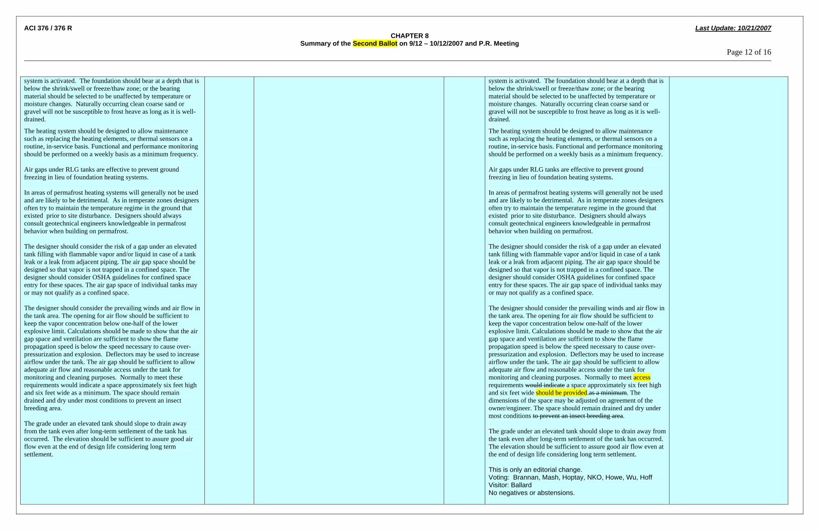
ACI 376 / 376 R Last Update: 10/21/2007 CHAPTER 8
Summary of the Second Ballot on 9/12 – 10/12/2007 and P.R. Meeting Page 12 of 16 system is activated. The foundation should bear at a depth that is below the shrink/swell or freeze/thaw zone; or the bearing material should be selected to be unaffected by temperature or moisture changes. Naturally occurring clean coarse sand or gravel will not be susceptible to frost heave as long as it is well-drained.
The heating system should be designed to allow maintenance such as replacing the heating elements, or thermal sensors on a routine, in-service basis. Functional and performance monitoring should be performed on a weekly basis as a minimum frequency. Air gaps under RLG tanks are effective to prevent ground freezing in lieu of foundation heating systems. In areas of permafrost heating systems will generally not be used and are likely to be detrimental. As in temperate zones designers often try to maintain the temperature regime in the ground that existed prior to site disturbance. Designers should always consult geotechnical engineers knowledgeable in permafrost behavior when building on permafrost. The designer should consider the risk of a gap under an elevated tank filling with flammable vapor and/or liquid in case of a tank leak or a leak from adjacent piping. The air gap space should be designed so that vapor is not trapped in a confined space. The designer should consider OSHA guidelines for confined space entry for these spaces. The air gap space of individual tanks may or may not qualify as a confined space. The designer should consider the prevailing winds and air flow in the tank area. The opening for air flow should be sufficient to keep the vapor concentration below one-half of the lower explosive limit. Calculations should be made to show that the air gap space and ventilation are sufficient to show the flame propagation speed is below the speed necessary to cause over-pressurization and explosion. Deflectors may be used to increase airflow under the tank. The air gap should be sufficient to allow adequate air flow and reasonable access under the tank for monitoring and cleaning purposes. Normally to meet these requirements would indicate a space approximately six feet high and six feet wide as a minimum. The space should remain drained and dry under most conditions to prevent an insect breeding area. The grade under an elevated tank should slope to drain away from the tank even after long-term settlement of the tank has occurred. The elevation should be sufficient to assure good air flow even at the end of design life considering long term settlement.
system is activated. The foundation should bear at a depth that is below the shrink/swell or freeze/thaw zone; or the bearing material should be selected to be unaffected by temperature or moisture changes. Naturally occurring clean coarse sand or gravel will not be susceptible to frost heave as long as it is well-drained.
The heating system should be designed to allow maintenance such as replacing the heating elements, or thermal sensors on a routine, in-service basis. Functional and performance monitoring should be performed on a weekly basis as a minimum frequency. Air gaps under RLG tanks are effective to prevent ground freezing in lieu of foundation heating systems. In areas of permafrost heating systems will generally not be used and are likely to be detrimental. As in temperate zones designers often try to maintain the temperature regime in the ground that existed prior to site disturbance. Designers should always consult geotechnical engineers knowledgeable in permafrost behavior when building on permafrost. The designer should consider the risk of a gap under an elevated tank filling with flammable vapor and/or liquid in case of a tank leak or a leak from adjacent piping. The air gap space should be designed so that vapor is not trapped in a confined space. The designer should consider OSHA guidelines for confined space entry for these spaces. The air gap space of individual tanks may or may not qualify as a confined space. The designer should consider the prevailing winds and air flow in the tank area. The opening for air flow should be sufficient to keep the vapor concentration below one-half of the lower explosive limit. Calculations should be made to show that the air gap space and ventilation are sufficient to show the flame propagation speed is below the speed necessary to cause over-pressurization and explosion. Deflectors may be used to increase airflow under the tank. The air gap should be sufficient to allow adequate air flow and reasonable access under the tank for monitoring and cleaning purposes. Normally to meet access requirements would indicate a space approximately six feet high and six feet wide should be provided.as a minimum. The dimensions of the space may be adjusted on agreement of the owner/engineer. The space should remain drained and dry under most conditions to prevent an insect breeding area. The grade under an elevated tank should slope to drain away from the tank even after long-term settlement of the tank has occurred. The elevation should be sufficient to assure good air flow even at the end of design life considering long term settlement. This is only an editorial change. Voting: Brannan, Mash, Hoptay, NKO, Howe, Wu, Hoff Visitor: Ballard No negatives or abstensions.

ACI 376 / 376 R Last Update: 10/21/2007 CHAPTER 8
Summary of the Second Ballot on 9/12 – 10/12/2007 and P.R. Meeting Page 13 of 16
1. The activities of this section regarding the measurement of movement of the inner tank in relation to the outer tank for radial-expansion & contraction, translational and rotational movement are typically associated with initial cooldown and may be better suited for the chapter 10 on Startup and Commissioning. This is to confirm allowable movement within the tank design basis. For routine operations after cooldown inner tank movement is very negligible and usually affected only by liquid level fluctuations or seismic events. 2. For concrete tanks, it is typically stated that no penetrations are allowed of the exterior wall but only through the roof. It would be interesting to see how the author plans to mount these probes, and replace them if they fail as they are buried inside never to be seen again. 3. For all the different sensors and detectors listed, it would be interesting to know the intent if these are wired into the plant control system historical recording or to a remote non-powered panel for periodic readings. 4. The term "Motion Sensors" implies dynamic sensing, not static like tank movement detectors that are non-powered devices where readings are taken at intervals like one time per month or one time per year at a remote non-powered panel. 5. The requirement for inclinometers has not been required in the past, and will be discovered from level surveys, and therefore unnecessary. 6. What is a corrosion monitoring system, there is no such thing? For buried structures with cathodic protection this would imply voltage readings. For above ground LNG tank structures, such as the roof and outer tank, visual inspections are performed to look for signs of active corrosion. Spot UT readings can be made to monitor for internal corrosion. What else is there?
Hatfield 8.7 – Foundation Performance Monitoring Details: The foundation performance shall be monitored for settlement, thermal conditions, seismic motions, and rotation of the inner tank. Devices such as permanent external benchmarks, permanent foundation benchmarks, inclinometers, thermal sensors, seismic motion detectors, and internal tank movement detectors shall be installed. A minimum of eight permanent benchmark points for measuring elevation shall be installed at equal intervals around the periphery of the tank foundation. Spacing between adjacent benchmarks shall not exceed 33 feet (10m). The points shall be referenced to at least one external permanent benchmark. Upon foundation completion and before wall construction the settlement monitoring benchmark points shall be installed and documented. Inclinometers shall be installed in the foundation if the expected settlement is greater than one-tenth the limiting values specified in Section 8.3.5. If the foundation is elevated such as by a pile cap or other means that allows the measurement of settlement under the tank, then inclinometers are not required. A thermal monitoring system shall be installed in the foundation to monitor the temperature of the foundation to assess the performance of bottom insulation and the air gap or heating system. The thermal monitoring system shall also be monitored to prevent adverse cryogenic effects on the ground below the foundation. The system sensors shall be on a pre-determined pattern that covers the bottom surface area. The conduits holding the sensors shall allow for ready servicing, removal and replacement of the thermal sensors. Motion detectors capable of recording horizontal, vertical and rotational motions of both the inner and outer tank shall be provided. A corrosion monitoring system shall be designed and installed on the outer tank, roof, and foundation.
Suggest removing the requirement for inner tank movement indicators since it is not required by the DOT and adding it to the commentary.
Hoptay
Committee proposed edited section 8.7 – Foundation Performance Monitoring Details: The foundation performance shall be monitored for settlement as listed in section 8.3.5, and thermal conditions, and seismic accelerations motions, and rotation of the inner tank. Devices such as permanent external benchmarks, permanent foundation benchmarks, inclinometers, thermal sensors, seismic accelerometers motion detectors, and internal tank movement detectors shall be installed. A minimum of eight permanent benchmark points for measuring elevation shall be installed at equal intervals around the periphery of the tank foundation. Spacing between adjacent benchmarks shall not exceed 33 feet (10m). The points shall be referenced to at least one external permanent benchmark. Upon foundation completion and before wall construction the settlement monitoring permanent benchmark points shall be installed and documented. Inclinometers shall be installed in the foundation for site classes other than Sa or Sb as defined in ASCE 7-05. if the expected settlement is greater than one-tenth the limiting values specified in Section 8.3.5. If the foundation is elevated such as by a pile cap or other means that allows the measurement of settlement under the tank, then inclinometers are not required. A thermal monitoring system shall be installed in the foundation to monitor the temperature of the foundation to assess the performance of bottom insulation and the air gap or heating system. The thermal monitoring system shall also be monitored to prevent adverse cryogenic effects on the ground below the foundation. The system sensors shall be on a pre-determined pattern that covers the bottom surface area. The conduits holding the sensors shall allow for ready servicing, removal and replacement of the thermal sensors. Motion detectors capable of recording horizontal, vertical and rotational motions of both the inner and outer tank shall be provided. A corrosion monitoring system shall be designed and installed on the outer tank, roof, and foundation. Hatfield comments:
1. Committee found persuasive. 2. Committee found persuasive and removed movement indicator requirement. 3. Committee found non-persuasive as this would not
CURRENT TEXT: 8.7 – Settlement Monitoring: Settlement shall be monitored periodically during the life of the facility, including during construction, at a minimum of quarter points during hydrotesting, commissioning and operation. A minimum of four permanent points for measuring elevation shall be installed on the tank foundation at equal intervals around the periphery. The points shall be referenced to at least one external permanent benchmark. Upon foundation completion and before wall construction the settlement monitoring points shall be surveyed and documented. Inclinometers shall be installed in the foundation if the expected settlement is greater than one-tenth the limiting values specified in Section 8.3.5. If the foundation is elevated such as by a pile cap or other means that allows measurement of settlement under the tank then inclinometers are not required. Why is a corrosion monitoring system necessary? (Powell) Move the following sentences to commentary. Devices such as permanent external benchmarks, permanent foundation benchmarks, inclinometers, thermal sensors, seismic accelerometers motion detectors, and internal tank movement detectors shall be installed. If the foundation is elevated such as by a pile cap or other means that allows the measurement of settlement under the tank, then inclinometers are not required. Committee recommends moving seismic monitoring requirements to seismic section. The structure will be provided with two accelerometers, one placed at
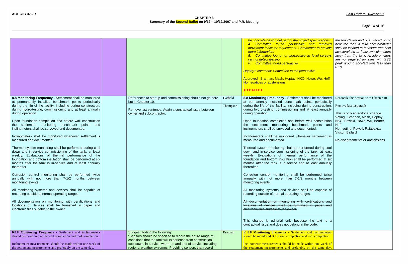
ACI 376 / 376 R Last Update: 10/21/2007 CHAPTER 8
Summary of the Second Ballot on 9/12 – 10/12/2007 and P.R. Meeting Page 14 of 16
be concrete design but part of the project specifications. 4. Committee found persuasive and removed movement indicator requirement. Commenter to provide more information. 5. Committee found non-persuasive as level surveys cannot detect dishing. 6. Committee found persuasive.
Hoptay’s comment: Committee found persuasive Approved: Brannan, Mash, Hoptay, NKO, Howe, Wu, Hoff No negatives or abstensions TO BALLOT
the foundation and one placed on or near the roof. A third accelerometer shall be located to measure free-field accelerations at least two diameters away from the tank. Accelerometers are not required for sites with SSE peak ground accelerations less than 0.1g.
References to startup and commissioning should not go here but in Chapter 10.
Hatfield 8.8 Monitoring Frequency - Settlement shall be monitored at permanently installed benchmark points periodically during the life of the facility, including during construction, during hydro-testing, commissioning and at least annually during operation. Upon foundation completion and before wall construction the settlement monitoring benchmark points and inclinometers shall be surveyed and documented. Inclinometers shall be monitored whenever settlement is measured and documented. Thermal system monitoring shall be performed during cool down and in-service commissioning of the tank, at least weekly. Evaluations of thermal performance of the foundation and bottom insulation shall be performed at six months after the tank is in-service and at least annually thereafter. Corrosion control monitoring shall be performed twice annually with not more than 7-1/2 months between monitoring events. All monitoring systems and devices shall be capable of recording outside of normal operating ranges. All documentation on monitoring with certifications and locations of devices shall be furnished in paper and electronic files suitable to the owner.
Remove last sentence. Again a contractual issue between owner and subcontractor.
Thompson
8.8 Monitoring Frequency - Settlement shall be monitored at permanently installed benchmark points periodically during the life of the facility, including during construction, during hydro-testing, commissioning and at least annually during operation. Upon foundation completion and before wall construction the settlement monitoring benchmark points and inclinometers shall be surveyed and documented. Inclinometers shall be monitored whenever settlement is measured and documented. Thermal system monitoring shall be performed during cool down and in-service commissioning of the tank, at least weekly. Evaluations of thermal performance of the foundation and bottom insulation shall be performed at six months after the tank is in-service and at least annually thereafter. Corrosion control monitoring shall be performed twice annually with not more than 7-1/2 months between monitoring events. All monitoring systems and devices shall be capable of recording outside of normal operating ranges. All documentation on monitoring with certifications and locations of devices shall be furnished in paper and electronic files suitable to the owner. This change is editorial only because the text is a contractual issue and does not belong in the code.
Reconcile this section with Chapter 10. Remove last paragraph This is only an editorial change. Voting: Brannan, Mash, Hoptay, NKO, Pawski, Howe, Wu, Berner, Hoff Non-voting: Powell, Rajapaksa Visitor: Ballard No disagreements or abstensions.
R8.8 Monitoring Frequency - Settlement and inclinometers should be monitored at the wall completion and roof completion. Inclinometer measurements should be made within one week of the settlement measurements and preferably on the same day.
Suggest adding the following: "Sensors should be specified to record the entire range of conditions that the tank will experience from construction, cool down, in-service, warm-up and end of service including regional weather extremes. Providing sensors that record
Brannan R 8.8 Monitoring Frequency - Settlement and inclinometers should be monitored at the wall completion and roof completion. Inclinometer measurements should be made within one week of the settlement measurements and preferably on the same day.

ACI 376 / 376 R Last Update: 10/21/2007 CHAPTER 8
Summary of the Second Ballot on 9/12 – 10/12/2007 and P.R. Meeting Page 15 of 16
particular segments of the potential range for better resolution is permissible and should be considered."
Thermal system monitoring is recommended to be continuous to detect changes in the insulation, and effects on the soil. Sensors should be specified to record the entire range of conditions that the tank will experience from construction, cool down, in-service, warm up, and end of service including regional weather extremes. Providing sensors that record particular segments of the potential range for better resolution is permissible and should be considered. Movement indicators should be monitored continuously.
NEGATIVE: References to startup and commissioning should not go here but in Chapter 10. A requirement for constant monitoring of inner tank movement is burdensome and not-warranted by industry historical experience. Nothing would be observed except during commissioning and a seismic event.
Hatfield
During the hydrotest, the settlement and inclinometer measurements should be on the same day. Thermal system monitoring is recommended to be continuous to detect changes in the insulation, and effects on the soil. Sensors should be specified to record the entire range of conditions that the tank will experience from construction, cool down, in-service, warm up, and end of service including regional weather extremes. Providing sensors that record particular segments of the potential range for better resolution is permissible and should be considered. Movement indicators should be monitored continuously. Hatfield’s comment: Committee found non-persuasive. Section 8.8 deals with foundation monitoring therefore frequency of monitoring should be addressed. Brannan’s comment: Withdrawn Approved: Brannan, Mash, Hoptay, NKO, Howe, Wu, Hoff No negatives or abstensions TO BALLOT
Revise the sentence: "Each lot of straight reinforcing and shape of bent bars and their location in ths structure shall be documented and the records kept readily available for review."
Brannan 8.9 – Inspection and Testing: During construction all materials testing and performance measurements on the deep foundation components shall be performed as required by the design engineer and geotechnical engineer. Documentation of all such results shall be available at all times to the engineers and owners and shall be provided in a quality assurance/quality control (QA/QC) system delivered in a form(s) acceptable to the engineers, owners and regulatory agencies. Such system shall be adequately detailed in order to identify precisely which component or material in the structure was tested. The precise location in the foundation of each pile, every load of concrete or component must be traceable. Each lot of straight reinforcing and shape of bent bars and their location in the structure shall be documented and the records shall be readily available. All mill certificates for lots of reinforcing must be documented and traceable. Records of all test results shall be preserved and disposition of failed materials documented. For concrete placed at the site the required results include truck batch tickets, the results of field tests on fresh concrete, and the results of compression or any other laboratory tests on sample cylinders, beams, cubes or test specimens. All documentation on QA/QC tests or certifications and locations shall be furnished in paper and electronic files suitable to the owner.
This reads like a contract from an owner. Delivery times for QC documentation and independent inspection requirements should not be mandated in this document. These are job specific contractual issues. I recommend using the first paragraph only.
Thompson
Move this section to section 9 Approved: Brannan, Mash, Hoptay, NKO, Howe, Wu, Hoff No negatives or abstentions
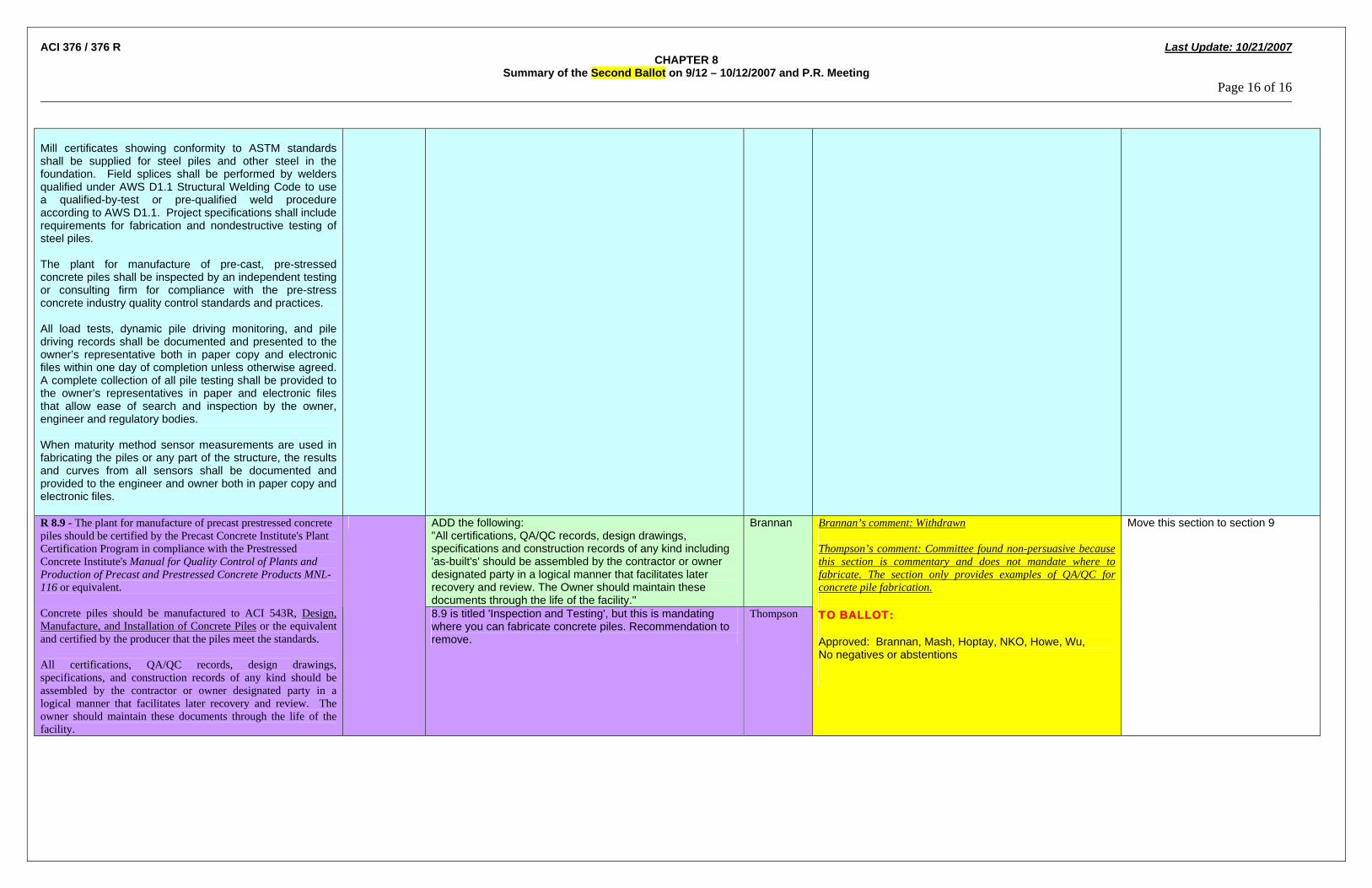
ACI 376 / 376 R Last Update: 10/21/2007 CHAPTER 8
Summary of the Second Ballot on 9/12 – 10/12/2007 and P.R. Meeting Page 16 of 16 Mill certificates showing conformity to ASTM standards shall be supplied for steel piles and other steel in the foundation. Field splices shall be performed by welders qualified under AWS D1.1 Structural Welding Code to use a qualified-by-test or pre-qualified weld procedure according to AWS D1.1. Project specifications shall include requirements for fabrication and nondestructive testing of steel piles. The plant for manufacture of pre-cast, pre-stressed concrete piles shall be inspected by an independent testing or consulting firm for compliance with the pre-stress concrete industry quality control standards and practices. All load tests, dynamic pile driving monitoring, and pile driving records shall be documented and presented to the owner’s representative both in paper copy and electronic files within one day of completion unless otherwise agreed. A complete collection of all pile testing shall be provided to the owner’s representatives in paper and electronic files that allow ease of search and inspection by the owner, engineer and regulatory bodies. When maturity method sensor measurements are used in fabricating the piles or any part of the structure, the results and curves from all sensors shall be documented and provided to the engineer and owner both in paper copy and electronic files.
ADD the following: "All certifications, QA/QC records, design drawings, specifications and construction records of any kind including 'as-built's' should be assembled by the contractor or owner designated party in a logical manner that facilitates later recovery and review. The Owner should maintain these documents through the life of the facility."
Brannan R 8.9 - The plant for manufacture of precast prestressed concrete piles should be certified by the Precast Concrete Institute's Plant Certification Program in compliance with the Prestressed Concrete Institute's Manual for Quality Control of Plants and Production of Precast and Prestressed Concrete Products MNL-116 or equivalent. Concrete piles should be manufactured to ACI 543R, Design, Manufacture, and Installation of Concrete Piles or the equivalent and certified by the producer that the piles meet the standards. All certifications, QA/QC records, design drawings, specifications, and construction records of any kind should be assembled by the contractor or owner designated party in a logical manner that facilitates later recovery and review. The owner should maintain these documents through the life of the facility.
8.9 is titled 'Inspection and Testing', but this is mandating where you can fabricate concrete piles. Recommendation to remove.
Thompson
Brannan’s comment: Withdrawn Thompson’s comment: Committee found non-persuasive because this section is commentary and does not mandate where to fabricate. The section only provides examples of QA/QC for concrete pile fabrication. TO BALLOT: Approved: Brannan, Mash, Hoptay, NKO, Howe, Wu, No negatives or abstentions
Move this section to section 9
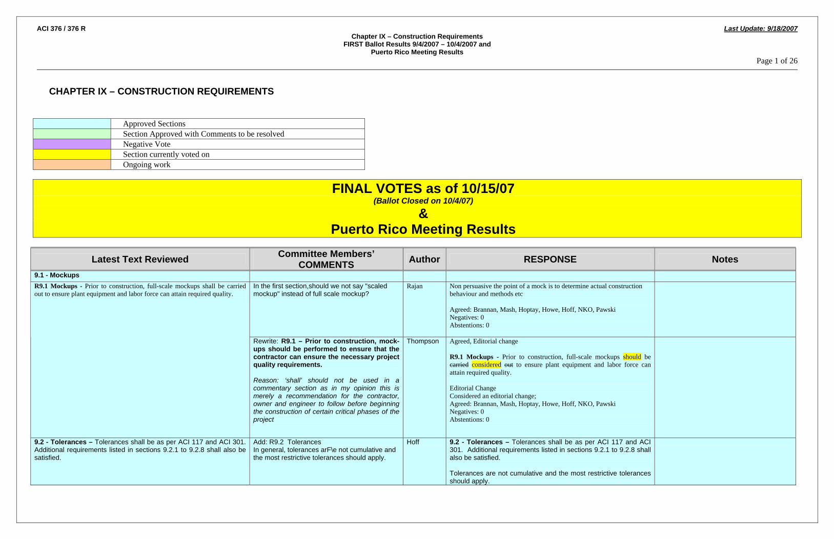
ACI 376 / 376 R Last Update: 9/18/2007 Chapter IX – Construction Requirements
FIRST Ballot Results 9/4/2007 – 10/4/2007 and Puerto Rico Meeting Results
Page 1 of 26
CHAPTER IX – CONSTRUCTION REQUIREMENTS
Approved Sections Section Approved with Comments to be resolved Negative Vote Section currently voted on Ongoing work
FINAL VOTES as of 10/15/07 (Ballot Closed on 10/4/07)
& Puerto Rico Meeting Results
Latest Text Reviewed Committee Members’ COMMENTS Author RESPONSE Notes
9.1 - Mockups In the first section,should we not say "scaled mockup" instead of full scale mockup?
Rajan Non persuasive the point of a mock is to determine actual construction behaviour and methods etc Agreed: Brannan, Mash, Hoptay, Howe, Hoff, NKO, Pawski Negatives: 0 Abstentions: 0
R9.1 Mockups - Prior to construction, full-scale mockups shall be carried out to ensure plant equipment and labor force can attain required quality.
Rewrite: R9.1 – Prior to construction, mock-ups should be performed to ensure that the contractor can ensure the necessary project quality requirements. Reason: ‘shall’ should not be used in a commentary section as in my opinion this is merely a recommendation for the contractor, owner and engineer to follow before beginning the construction of certain critical phases of the project
Thompson Agreed, Editorial change R9.1 Mockups - Prior to construction, full-scale mockups should be carried considered out to ensure plant equipment and labor force can attain required quality. Editorial Change Considered an editorial change; Agreed: Brannan, Mash, Hoptay, Howe, Hoff, NKO, Pawski Negatives: 0 Abstentions: 0
9.2 - Tolerances – Tolerances shall be as per ACI 117 and ACI 301. Additional requirements listed in sections 9.2.1 to 9.2.8 shall also be satisfied.
Add: R9.2 Tolerances In general, tolerances arF\e not cumulative and the most restrictive tolerances should apply.
Hoff 9.2 - Tolerances – Tolerances shall be as per ACI 117 and ACI 301. Additional requirements listed in sections 9.2.1 to 9.2.8 shall also be satisfied. Tolerances are not cumulative and the most restrictive tolerances should apply.

ACI 376 / 376 R Last Update: 9/18/2007 Chapter IX – Construction Requirements
FIRST Ballot Results 9/4/2007 – 10/4/2007 and Puerto Rico Meeting Results
Page 2 of 26
Latest Text Reviewed Committee Members’ COMMENTS Author RESPONSE Notes
Considered an editorial change; Agreed: Brannan, Mash, Hoptay, Howe, Wu, NKO Visitor; Ballard Negatives: 0 Abstentions: 0
9.2.1 - Tolerances for Cross Sectional Dimensions - The variation in cross sectional dimensions of slabs shall be as follows;
a) ±3/8” where the section thickness is less than or equal to 8 in. b) ±½” where the section thickness exceeds 8 in.
The cross sectional dimensions of walls shall not vary by more than ±¼” from the specified thickness. The cross sectional dimensions of dome roof shall not vary by more than ±½” from the specified thickness.
In Section 9.2.1 I suggest that for walls with Shotcrete the tolerance on thickness should be changed from 1/4" to +/- 1/2".
Berner Verify Tolerances (Editorial). Otherwise text stays the same 9.2.1 - Tolerances for Cross Sectional Dimensions - The variation in cross sectional dimensions of slabs shall be as follows;
c) ±3/8” where the section thickness is less than or equal to 8 in.
d) ±½” where the section thickness exceeds 8 in.
The cross sectional dimensions of walls shall not vary by more than ±¼” from the specified thickness. The cross sectional dimensions of dome roof shall not vary by more than ±½” from the specified thickness.
Check tolerances in accordance with ACI 350
R9.2.1 - Tolerances for Cross Sectional Dimensions – These tolerances are typically in line with established LNG/LPG practice.
9.2 - Tolerances – Tolerances shall be as per ACI 117 and ACI 301. Additional requirements listed in sections 9.2.1 to 9.2.8 shall also be satisfied.
9.2.2 – Variation in Roundness - The maximum permissible deviation from the base slab radius measured to the outside face of the base slab shall be the lesser of
a) 0.10% of the base slab radius b) 1.5”
Additionally under no circumstances shall the tolerance be less than ±¾”. The maximum permissible deviation from the specified tank wall radius measured to the inside face of the tank wall at the bottom of the wall shall be the lesser of
a) 0.06% of the tank radius b) 1”
Under no circumstances shall target deviation be less than ±½”. The maximum permissible deviation from the specified tank wall radius measured to the inside face of the tank wall at the top of the wall shall be the lesser of
a) 0.10% of the tank radius b) 1.5”
Under no circumstances shall the target deviation be less than ±¾”.

ACI 376 / 376 R Last Update: 9/18/2007 Chapter IX – Construction Requirements
FIRST Ballot Results 9/4/2007 – 10/4/2007 and Puerto Rico Meeting Results
Page 3 of 26
Latest Text Reviewed Committee Members’ COMMENTS Author RESPONSE Notes
Intermediate tolerances between the bottom and top of the wall may be interpolated.
In the second paragraph under R9.2.2 what are the "significant tolerance issues?"
Allen R9.2.2 - Variation in roundness - Tolerances for wall roundness at the bottom of the tank are normally documented as ±1” at base of the wall for large diameter LNG tanks. In order to cover the full spectrum of potential tank diameters and to introduce sensible upper bound values clauses a) and b) have been introduced. ACI 372/373/350 states “maximum permissible deviation from the specified tank radius should be 0.1% of the radius” which could result is significant tolerance issues out with normal construction practice. i.e for a 40m radius tank the deviation would be 40mm. (Normally this would be 1”). For alignment the tolerance has been set at .06% of the tank radius which conforms to existing practice (40m radius tank =25mm deviation). Due to the incorporation of 0.06%xR the tolerance will float between lower and upper bound limits for tanks in the radius range of 69.5’ and 138’. Tanks smaller than 69.5’ will have a permitted deviation of ±½”. Similarly tanks larger than 138’ will have a permitted deviation of ±1” Deviations at the top of the tank reflect existing construction practice and facilitate a range of tank diameters.
The second and third paragraph are mixing metric units in the text where everything else is in English units. Needs to be corrected.
Hoff
Action; Remove significant from 2nd sentence Action; Amend for units to be consistent in US units. R9.2.2 - Variation in roundness - Tolerances for wall roundness at the bottom of the tank are normally documented as ±1” at base of the wall for large diameter LNG tanks. In order to cover the full spectrum of potential tank diameters and to introduce sensible upper bound values clauses a) and b) have been introduced. ACI 372/373/350 states “maximum permissible deviation from the specified tank radius should be 0.1% of the radius” which could result is significant tolerance issues out with normal construction practice. i.e for a 130ft radius tank the deviation would be 1.5”. (Normally this would be 1”). For alignment the tolerance has been set at .06% of the tank radius which conforms to existing practice (40m radius tank =25mm deviation). Due to the incorporation of 0.06%xR the tolerance will float between lower and upper bound limits for tanks in the radius range of 69.5’ and 138’. Tanks smaller than 69.5’ will have a permitted deviation of ±½”. Similarly tanks larger than 138’ will have a permitted deviation of ±1” Deviations at the top of the tank reflect existing construction practice and facilitate a range of tank diameters. Considered an editorial change; Agreed: Brannan, Mash, Hoptay, Howe, Wu, NKO Visitor; Ballard Negatives: 0 Abstentions: 0
Notes Editorial committee may wish to review and edit sections containing examples
9.2.3 - Localized Tank Radius - The maximum permissible deviation of the tank wall radius measured along any 10 ft. of circumference shall be 10% of the wall radius. The maximum permissible deviation of the base slab radius measured along any 10 ft. of circumference shall be 20% of the base slab radius.
ACI 350 adopts the following “The maximum permissible deviation of the tank wall radius measured along any 10 ft. of circumference shall be 5% of the core wall thickness.” In practice this infers extremely“tight” construction criteria that in the field are practically unmeasurable. i.e For a 10 ft. circumference length on a 138’ radius tank the rise (distance measured normal from the chord to the

ACI 376 / 376 R Last Update: 9/18/2007 Chapter IX – Construction Requirements
FIRST Ballot Results 9/4/2007 – 10/4/2007 and Puerto Rico Meeting Results
Page 4 of 26
Latest Text Reviewed Committee Members’ COMMENTS Author RESPONSE Notes
perimeter) is 1.087”. Assuming a 2 ft wall thickness (generous) the maximum radius is 138+2*5/100=138.1ft and the rise 1.086’. If interpreted correctly this infers a level of detection on site of 1.087-1.086=0.001” (.02mm) which is unrealistic/unachieveable. Ed proposes amending the localization of tank radius to be 10% for the wall and 20% for the base slab. In practice this infers measurable field deviations. For the 138ftexample stated this infers a rise of 1.087”. Based on 10% the upperbound radius is 1.1*138=151.8ft and corresponding rise 0.988”. The difference detectable on site should therefore be .099” (2.5mm). One disadvantage with this approach is that the allowable deviation increases with decreasing diameter which is non-sensical. In light of this it is prudent to use a constant detectable/measurable value similar to those adopted by API. Alternately we may elect to avoid stipulation of localized radius this is however a clause referenced in ACI 350 Appendix F. Late vote Hjorteset Negative – The 10% value and the 20% value must be a typo.
9.2.4 - Vertical Walls a) Walls shall be plumb within 1/4” per 10 ft of vertical dimension. b) The variation is verticality measured from the bottom of the wall
to the point of consideration shall not be more than 1”.
ACI 350 paragraph F.4.6.3 adopts 3/8” however normal industry practice for LNG/LPG adopts ¼”. For consistency ¼” proposed.
9.2.5 - Level Alignment a) The variation in level from specified elevations for any
completed surface excluding the support underneath the inner tank wall shall be limited to ±½”.
b) Along any 10 ft straight line the difference in elevation of any two points shall not exceed ±3/16”.
c) In the instance of the edge of the base slab, and walls along
In accordance with API 620 §6.5.6.2 and industry practice Clause introduced to tighten tolerances at the at the edge of the base slab and wall/base junctions where interfacing with vapor barrier inserts and wall forms etc will
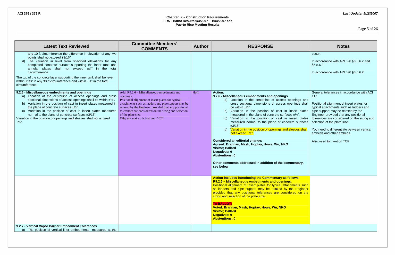
ACI 376 / 376 R Last Update: 9/18/2007 Chapter IX – Construction Requirements
FIRST Ballot Results 9/4/2007 – 10/4/2007 and Puerto Rico Meeting Results
Page 5 of 26
Latest Text Reviewed Committee Members’ COMMENTS Author RESPONSE Notes
any 10 ft circumference the difference in elevation of any two points shall not exceed ±3/16”.
d) The variation in level from specified elevations for any completed concrete surface supporting the inner tank and annular plates shall not exceed ±¼” in the total circumference.
The top of the concrete layer supporting the inner tank shall be level within ±1/8” in any 30 ft circumference and within ±¼” in the total circumference.
occur. In accordance with API 620 §6.5.6.2 and §6.5.6.3 In accordance with API 620 §6.5.6.2
9.2.6 - Miscellaneous embedments and openings a) Location of the centerline of access openings and cross
sectional dimensions of access openings shall be within ±½”. b) Variation in the position of cast in insert plates measured in
the plane of concrete surfaces ±½”. c) Variation in the position of cast in insert plates measured
normal to the plane of concrete surfaces ±3/16”. Variation in the position of openings and sleeves shall not exceed ±¼”.
Add: R9.2.6 – Miscellaneous embedments and openings. Positional alignment of insert plates for typical attachments such as ladders and pipe support may be relaxed by the Engineer provided that any positional tolerances are considered on the sizing and selection of the plate size. Why not make this last item “C”?
Hoff Action: 9.2.6 - Miscellaneous embedments and openings
a) Location of the centerline of access openings and cross sectional dimensions of access openings shall be within ±½”.
b) Variation in the position of cast in insert plates measured in the plane of concrete surfaces ±½”.
c) Variation in the position of cast in insert plates measured normal to the plane of concrete surfaces ±3/16”.
d) Variation in the position of openings and sleeves shall not exceed ±¼”.
Considered an editorial change; Agreed: Brannan, Mash, Hoptay, Howe, Wu, NKO Visitor; Ballard Negatives: 0 Abstentions: 0 Other comments addressed in addition of the commentary, see below
General tolerances in accordance with ACI 117 Positional alignment of insert plates for typical attachments such as ladders and pipe support may be relaxed by the Engineer provided that any positional tolerances are considered on the sizing and selection of the plate size. You need to differentiate between vertical embeds and other embeds
Also need to mention TCP
Action includes introducing the Commentary as follows R9.2.6 – Miscellaneous embedments and openings. Positional alignment of insert plates for typical attachments such as ladders and pipe support may be relaxed by the Engineer provided that any positional tolerances are considered on the sizing and selection of the plate size. To BALLOT; Voted: Brannan, Mash, Hoptay, Howe, Wu, NKO Visitor; Ballard Negatives: 0 Abstentions: 0
9.2.7 - Vertical Vapor Barrier Embedment Tolerances a) The position of vertical liner embedments measured at the

ACI 376 / 376 R Last Update: 9/18/2007 Chapter IX – Construction Requirements
FIRST Ballot Results 9/4/2007 – 10/4/2007 and Puerto Rico Meeting Results
Page 6 of 26
Latest Text Reviewed Committee Members’ COMMENTS Author RESPONSE Notes
bottom of the wall in the plane of the concrete surface shall be shall ±¼”.
b) Vertical liner embedments shall be plumb within ±½” when measured from the bottom to the top of the wall.
The variation in position of vertical liner embedments measured normal to the concrete surface shall be +0”, -1/8”. R9.2.7 - Vertical Vapor Barrier Embedment Tolerances - Negative tolerance infers recessed embedments under such conditions that the concrete adjacent to the embedment should be feathered to avoid step changes and facilitate vapour barrier connection.
he same sentence appears under R9.2.7 and R9.2.8. I suggest rewording this sentence into two as follows: "Negative tolerance infers recessed embedments. Under such conditions the concrete adjacent to the embedment should be feathered to avoid step changes and facilitate vapor barrier connection."
Allen Non persuasive, feathered has different meaning in US workplace. Change feathered to sloped. Innappropriate to link together 9.2.7 and 9.2.8. Leave to editorial review R9.2.7 - Vertical Vapor Barrier Embedment Tolerances - Negative tolerance infers recessed embedments under such conditions that the concrete adjacent to the embedment should be feathered sloped to avoid step changes and facilitate vapour barrier connection. Editorial Change Considered an editorial change; Agreed: Brannan, Mash, Hoptay, Howe, Hoff, NKO, Pawski Negatives: 0 Abstentions: 0
Editorial committee to review 9.2.7 and 9.2.8 and overlap
9.2.8 - Horizontal Thermal Corner Protection Embedments a) The elevation of horizontal thermal corner embedments shall
be within ±¼”. b) The variation in position of horizontal embedments measured
normal to the concrete surface shall be +0”, -1/8”.
R9.2.8 - Horizontal Thermal Corner Protection Embedments - Negative tolerance infers recessed embedments under such conditions that the concrete adjacent to the embedment should be feathered to avoid step changes and facilitate vapour barrier connection.
he same sentence appears under R9.2.7 and R9.2.8. I suggest rewording this sentence into two as follows: "Negative tolerance infers recessed embedments. Under such conditions the concrete adjacent to the embedment should be feathered to avoid step changes and facilitate vapor barrier connection."
Allen Non persuasive, feathered has different meaning in US workplace. Change feathered to sloped. Innappropriate to link together 9.2.7 and 9.2.8. Leave to editorial review R9.2.8 - Horizontal Thermal Corner Protection Embedments - Negative tolerance infers recessed embedments under such conditions that the concrete adjacent to the embedment should be feathered sloped to avoid step changes and facilitate vapour barrier connection. Editorial Change Considered an editorial change; Agreed: Brannan, Mash, Hoptay, Howe, Hoff, NKO, Pawski Negatives: 0 Abstentions: 0
Editorial committee to review 9.2.7 and 9.2.8 and overlap

ACI 376 / 376 R Last Update: 9/18/2007 Chapter IX – Construction Requirements
FIRST Ballot Results 9/4/2007 – 10/4/2007 and Puerto Rico Meeting Results
Page 7 of 26
Latest Text Reviewed Committee Members’ COMMENTS Author RESPONSE Notes
9.3 - Shotcrete - Unless otherwise indicated here, shotcrete shall meet the requirements of ACI 506.2.
9.3.1 - Proportioning Shotcrete - Shotcrete shall be proportioned in accordance with the following requirements :
a) Wire coat shall consist of one part Portland cement and not more than three parts fine aggregate by weight.
b) Body coat shall consist of one part Portland cement and not more than four parts fine aggregate by weight.
Add: c) Proportioning shall provide a 28-day minimum compressive strength of shotcrete not less than 4500 psi.
Hoff Action include section from ACI 350, see Hoff. 9.3.1 - Proportioning Shotcrete - Shotcrete shall be proportioned in accordance with the following requirements :
a) Wire coat shall consist of one part Portland cement and not more than three parts fine aggregate by weight.
b) Body coat shall consist of one part Portland cement and not more than four parts fine aggregate by weight.
c) Proportioning shall provide a 28-day minimum compressive strength of shotcrete not less than 4500 psi. To Ballot Voted: Brannan, Mash, Hoptay, Howe, Wu, NKO Negatives: 0 Abstentions: 0 Comment found persuasive and text amended accordingly
9.3.2 - Shotcrete Construction Procedures - Procedures for shotcrete construction of primary and secondary containers comprising circular wire and strand shall be as specified in ACI 506.2 except as modified herein.
9.3.3 - Shotcrete Overcoat
9.3.3.1 - Externally applied circumferential prestressed reinforcement shall be protected against corrosion and other damage by a shotcrete overcoat.
R9.3.3.1 - The shotcrete covercoat generally consists of two or more coats: a wire coat placed on the pre-stressed reinforcement, and a bodycoat placed on the wire coat. If the covercoat is placed in one coat, the mixture should be the same as the wire coat.
9.3.3.2 - Each layer of circumferential prestressed wire or strand shall be covered first with a wirecoat of cement mortar applied by the pneumatic process as soon as practical after prestressing. The shotcrete shall be wet, but not dripping, and provide a minimum cover over the wire of ¼ in. The nozzle shall be held at a small upward angle not exceeding 5 degrees and shall be constantly moving, without shaking, and always pointing in a radial direction toward the center of the tank. The nozzle distance from the prestressed reinforcement shall be such that shotcrete does not build up over or
Editorial Comment: Delete: “without shaking” After the third sentence add: “The nozzle shall deliver a steady, uninterrupted flow of shotcrete.”
Brannan Persuasive 9.3.3.2 - Each layer of circumferential prestressed wire or strand shall be covered first with a wirecoat of cement mortar applied by the pneumatic process as soon as practical after prestressing. The shotcrete shall be wet, but not dripping, and provide a minimum cover over the wire of ¼ in. The nozzle shall be held at a small upward angle not exceeding 5 degrees and shall be constantly moving, without shaking, and always pointing in a radial direction

ACI 376 / 376 R Last Update: 9/18/2007 Chapter IX – Construction Requirements
FIRST Ballot Results 9/4/2007 – 10/4/2007 and Puerto Rico Meeting Results
Page 8 of 26
Latest Text Reviewed Committee Members’ COMMENTS Author RESPONSE Notes
cover the front faces of the wires or strands until the spaces between them are filled.
toward the center of the tank. The nozzle shall deliver a steady, uninterrupted flow of shotcrete. The nozzle distance from the prestressed reinforcement shall be such that shotcrete does not build up over or cover the front faces of the wires or strands until the spaces between them are filled. Editorial Change Considered an editorial change; Agreed: Brannan, Mash, Hoptay, Howe, Hoff, NKO Negatives: 0 Abstentions: 0
R9.3.3.2 - Nozzle distance and wetness of mixture are equally critical to satisfactory encasement of pre-stressed reinforcement. If the nozzle is held too far back, the shotcrete will deposit on the face of the wire or strand at the same time that it is building up on the core wall, thereby not filling the space behind them. This condition is readily apparent and should be corrected immediately by adjusting the nozzle distance and, if necessary, the water content.
Change “ is prohibited” to “should be prohibited>”
Hoff Not relevant to section Agreed: Brannan, Mash, Hoptay, Howe, Wu, NKO Visitor; Ballard Negatives: 0 Abstentions: 0
9.3.3.3 - The wire coat shall be damp-cured by a constant spray or trickling of water down the wall, except that curing shall be permitted to be interrupted during continuous prestressing operations. Curing compounds shall not be used on surfaces that will receive additional shotcrete.
R9.3.3.3 - Curing compounds applied to intermediate layers of shotcrete may interfere with the bonding of subsequent layers and thus their use is prohibited
Editorial Comment: Add: “Maintaining the relative humidity, naturally or artificially, near or above 95% over the shotcrete surface is an acceptable method of curing.”
Brannan Persuasive, proposed text as follows R9.3.3.3 - Curing compounds applied to intermediate layers of shotcrete may interfere with the bonding of subsequent layers and thus their use is prohibited. Maintaining the relative humidity, naturally or artificially, near or above 95% over the shotcrete surface is an acceptable method of curing in accordance with ACI 506R. To Ballot Voted: Brannan, Mash, Hoptay, Howe, Hoff, NKO Negatives: 0 Abstentions: 0
ACI 350 original source of text Brannan to provide text source “ACI XXX “shotcrete manual for inclusion

ACI 376 / 376 R Last Update: 9/18/2007 Chapter IX – Construction Requirements
FIRST Ballot Results 9/4/2007 – 10/4/2007 and Puerto Rico Meeting Results
Page 9 of 26
Latest Text Reviewed Committee Members’ COMMENTS Author RESPONSE Notes
9.3.3.4 - Shotcrete material placed incorrectly shall be removed and replaced.
R9.3.3.4 - After the wire coat is in place, visual inspection can immediately determine whether or not proper encasement has been achieved. Where the reinforcement patterns show on the surface as distinct continuous horizontal ridges, the shotcrete has not been driven behind the reinforcement and voids can be expected. If, however, the surface is substantially flat and shows virtually no pattern, a minimum of voids is likely.
9.3.3.5 - A body coat providing a minimum of 1 in. cover over the outside layer of prestressed reinforcement shall be applied over the last layer of wire coat.
• If the body coat is not applied as a part of the wire coat, laitence and loose particles shall be removed from the surface of the wire coat prior to the application of the body coat.
• Thickness control shall be as required by ACI 506.2. • The completed shotcrete coating shall be cured for at least 7
days using methods specified by ACI 506.2.
R9.3.3.5 - Curing should be started as soon as possible without damaging the shotcrete.
Editorial Comment: Revise to read: “Curing should be started immediately after shotcrete placement without damaging the shotcrete.”
Brannan Persuasive, considered editorial R9.3.3.5- Curing should be started immediately after shotcrete placement without damaging the shotcrete. Editorial Change Considered an editorial change; Agreed: Brannan, Mash, Hoptay, Howe, Hoff, NKO Negatives: 0 Abstentions: 0
9.3.3.1 - After the bodycoat has cured, the surface shall be checked for “hollow sounding” or “drummy” spots by tapping with a light hammer or similar tool. Such spots indicate a lack of bond between coats and shall be repaired. These areas shall be repaired by removal and replacement with properly bonded shotcrete, or by epoxy injection.
9.3.4 - Thickness control of shotcrete core walls and covercoats
R9.1.1 R9.3.4 - Thickness control of shotcrete core walls and covercoats
9.3.4.1 - Positive methods shall be used to establish uniform and Add: Hoff Action,

ACI 376 / 376 R Last Update: 9/18/2007 Chapter IX – Construction Requirements
FIRST Ballot Results 9/4/2007 – 10/4/2007 and Puerto Rico Meeting Results
Page 10 of 26
Latest Text Reviewed Committee Members’ COMMENTS Author RESPONSE Notes
correct thickness of shotcrete core.
9.3.4.2 When screed wires are used for thickness control, they shall be spaced a maximum of 36 in. apart circumferentially.
R9.3.4.1 - Vertical screed wires are the normal method used to establish uniform and correct thickness of shotcrete. Wires should be installed under tension, defining the outside surface of the shotcrete from top to bottom. Wires generally are 18- to 20-gauge high-tensile-strength steel wire. Other methods may be used that will provide positive control of the thickness
Considered persuasive add to existing R9.3.4.1 commentary. R9.3.4.1 - Vertical screed wires are the normal method used to establish uniform and correct thickness of shotcrete and should be spaced not more than 36in apart circumferentially. Wires should be installed under tension, defining the outside surface of the shotcrete from top to bottom. Wires generally are 18- to 20-gauge high-tensile-strength steel wire. Other methods may be used that will provide positive control of the thickness To Ballot Voted: Brannan, Mash, Hoptay, Howe, Wu, NKO Negatives: 0 Abstentions: 0
9.4 - Post Tensioning
9.4.1 - Ducts for grouted tendons shall be mortar-tight and non reactive with concrete, tendons, or filler material.
Add: R9.4.1 Consideration should be given to including additional ducts at appropriate locations in case a duct is damaged prior to threading of tendons and cannot be used. All unused ducts should be grouted.
Hoff Intent persuasive addressed as follows; R9.4.1 - Consideration should be given to including additional strand capacity within the anchorage selection to enable introduction of prestressing force should an adjacent duct become blocked. Equilibrium and distribution steel should be sized for the larger anchorage. To Ballot Voted: Brannan, Mash, Hoptay, Howe, NKO, Hoff Negatives: 0 Abstentions: 0
9.4.2 - Ducts for grouted single wire, strand, or bar tendons shall have an inside diameter at least +¼ in. larger than tendon diameter.
9.4.3 - Ducts for grouted multiple wire, strand, or bar tendons shall have an inside cross-sectional area at least two times area of tendons.
Lte vote – Hjorteset Comment – two times the area of tendons seems to be small. I believe I have seen requirements for two and half times area of tendons. The committee may want to say something about how to deal with the relative small radiuses occurring in the

ACI 376 / 376 R Last Update: 9/18/2007 Chapter IX – Construction Requirements
FIRST Ballot Results 9/4/2007 – 10/4/2007 and Puerto Rico Meeting Results
Page 11 of 26
Latest Text Reviewed Committee Members’ COMMENTS Author RESPONSE Notes
vertical tendons. I.e. no duct allowed, pipe steel should be used.
9.4.4 - Ducts shall be maintained free of water if members to be grouted are exposed to temperatures below freezing prior to grouting.
9.4.5 - Vent holes shall be provided adjacent to the anchorages and at high points of the ducts to assist with air removal.
R9.4.5 - Vent holes shall be provided at anchorage locations at high points and at positions recommended by the Post tensioning supplier to ensure proper grouting quality.
9.4.6 – Vertical Tendons - Vertical tendon shall be filled from the bottom.
9.4.6 – Grout for Bonded Prestressing Tendons - Grout trials shall be used to ensure the following;
• The grout has not shrunk away from the duct wall or strands whereby creating voids within the system
• The grout has the correct flow characteristics to reach each of the vent points (where provided) and to completely fill the duct.
• The theoretical grout consumption
R9.4.6 – Grout for Bonded Prestressing Tendons - Full scale grout tests are performed on the horizontal tendons to specifically demonstrate the selection of tendon and distribution of vent tubes and selection of pumping equipment. After the grout trials the tendon is cut transversely and inspected prior to commencement of grouting operations proper. Grout provides bond between the post-tensioning tendons and the concrete and by which corrosion protection of the tendons is assured. Proper grout and grouting procedures, therefore, play an important part in post-tensioned construction. Reference PT manual.. Past success with grout for bonded prestressing tendons has been with Portland cement as the cementing material. A blanket endorsement of all cementitious materials (defined in Chapter II) for use with this grout is deemed inappropriate because of a lack of experience or tests with cementitious materials other than Portland cement and a concern that some cementitious materials might introduce chemicals listed as harmful to tendons in R18.16.2. Thus, “Portland cement” in 18.16.1 and “water-cement ratio” in 18.16.3.3 are retained in this edition of the code.
ASTM C494?? Hoff Comment not relevant to this section, confirmed by Messr Hoff and withdrawn.
Include reference to PT Manual
9.4.7 - Grout shall consist of Portland cement and water; or Portland cement, sand, and water; or a 100 % solids, two-component epoxy

ACI 376 / 376 R Last Update: 9/18/2007 Chapter IX – Construction Requirements
FIRST Ballot Results 9/4/2007 – 10/4/2007 and Puerto Rico Meeting Results
Page 12 of 26
Latest Text Reviewed Committee Members’ COMMENTS Author RESPONSE Notes
resin system. R9.4.7 - Epoxy grout has been used in limited applications. Caution is recommended in its selection and use. Properties of the material should be reviewed including differences in the coefficient of thermal expansion and heat generation.
9.4.8 - Grout material shall conform to the following requirements: a) Cement for grouting operations shall be Type I or Type II in
accordance with ASTM C150. b) The minimum compressive strength of grout shall be 6000psi
at 28 days tested in accordance with ASTM C109. c) Water cement ratio shall not exceed 0.45 by weight of
cement. d) Sand, if used, shall conform to “Standard Specification for
Aggregate for Masonry Mortar” (ASTM C 144) except that gradation shall be permitted to be modified as necessary to obtain satisfactory workability.
e) Admixtures conforming to (insert reference) and known to have no injurious effects on grout, steel, or concrete shall be permitted. Calcium chloride shall not be used.
f) Bleeding of the grout shall not exceed 2% of the volume for the first 3 hours after mixing, nor 4% total at any time. All separated water shall be reabsorbed within 24 hours.
g) Epoxy grout shall be moisture insensitive with a minimum compressive strength of 125 percent of the design concrete compressive strength.
ASTM C 494??? Hoff Editoral Change include reference to ASTM C494 9.4.8 - Grout material shall conform to the following requirements:
h) Cement for grouting operations shall be Type I or Type II in accordance with ASTM C150.
i) The minimum compressive strength of grout shall be 6000psi at 28 days tested in accordance with ASTM C109.
j) Water cement ratio shall not exceed 0.45 by weight of cement.
k) Sand, if used, shall conform to “Standard Specification for Aggregate for Masonry Mortar” (ASTM C 144) except that gradation shall be permitted to be modified as necessary to obtain satisfactory workability.
l) Admixtures conforming to (ASTM C494) and known to have no injurious effects on grout, steel, or concrete shall be permitted. Calcium chloride shall not be used.
m) Bleeding of the grout shall not exceed 2% of the volume for the first 3 hours after mixing, nor 4% total at any time. All separated water shall be reabsorbed within 24 hours.
n) Epoxy grout shall be moisture insensitive with a minimum compressive strength of 125 percent of the design concrete compressive strength.
Considered an editorial change; Agreed: Brannan, Mash, Hoptay, Howe, NKO Negatives: 0 Abstentions: 0
R9.4.8 - The limitations on admixtures in (insert reference) apply to grout. Substances known to be harmful to prestressing tendons, grout, or concrete are chlorides, fluorides, sulfites, and nitrates. Aluminum powder or other expansive admixtures, when approved, should produce an unconfined expansion of 5 to 10 percent. Neat cement grout is used in almost all building construction. Only with large ducts having large void areas should the advantages of using finely graded sand in the grout
ASTM C 494??? Hoff Persuasive R9.4.8 - The limitations on admixtures in ASTM C494 apply to grout. Substances known to be harmful to prestressing tendons, grout, or concrete are chlorides, fluorides, sulfites, and nitrates. Aluminum powder or other expansive admixtures, when approved, should produce an unconfined expansion of 5 to 10 percent. Neat cement grout is used in almost all building construction. Only with large ducts

ACI 376 / 376 R Last Update: 9/18/2007 Chapter IX – Construction Requirements
FIRST Ballot Results 9/4/2007 – 10/4/2007 and Puerto Rico Meeting Results
Page 13 of 26
Latest Text Reviewed Committee Members’ COMMENTS Author RESPONSE Notes
be considered. Admixtures are generally used to increase workability, reduce bleeding and shrinkage, or provide expansion. This is especially desirable for grouting of vertical tendons.
having large void areas should the advantages of using finely graded sand in the grout be considered. Admixtures are generally used to increase workability, reduce bleeding and shrinkage, or provide expansion. This is especially desirable for grouting of vertical tendons. Considered an editorial change; Agreed: Brannan, Mash, Hoptay, Howe, NKO, Hoff Negatives: 0 Abstentions: 0
9.4.9 – Grout Proportions
9.4.9.1 - Proportions of materials for grout shall be based on either of the following:
a) Results of tests on fresh and hardened grout prior to beginning grouting operations, or
b) Prior documented experience with similar materials and equipment and under comparable field conditions.
R9.4.9.1 - Grout proportioned in accordance with these provisions will generally lead to 7-day compressive strength on standard 2-in. cubes in excess of 2500 psi and 28-day strengths of about 4000 psi. The handling and placing properties of grout are usually given more consideration than strength when designing grout mixtures
R9.4.9.1 indicates that grout proportioned in accordance with these provisions will produce 28 day compressive strengths of about 4000 psi. This is inconsistent with 9.4.8 which requires a minimum strength of 6000 psi.
Hoptay R9.4.9.1 - Grout proportioned in accordance with these provisions will generally lead to 7-day compressive strength on standard 2-in. cubes in excess of 2500 psi and 28-day strengths of about 4000 psi. The handling and placing properties of grout are usually given more consideration than strength when designing grout mixtures Hoptay to review comment and revert
Author to review comment and revert
9.4.9.2 - Cement used in the work shall correspond to that on which selection of grout proportions was based.
9.4.9.3 - Water content shall be minimum necessary for proper pumping of grout; however, water cement ratio shall not exceed 0.45 by weight.
Late vote – Hjorteset Comment – Is the 0.45 value high if the tendons are used for the primary tank? Could there be freeze damage at cryogenic temperatures.
9.4.9.4 - Water shall not be added to increase grout flowability that has been decreased by delayed use of grout.
9.4.9.5 - Epoxy grout shall have demonstrated by tests or experience to exhibit acceptable pumpability and low exothermic
9.4.10 – Grout Mixing and Pumping
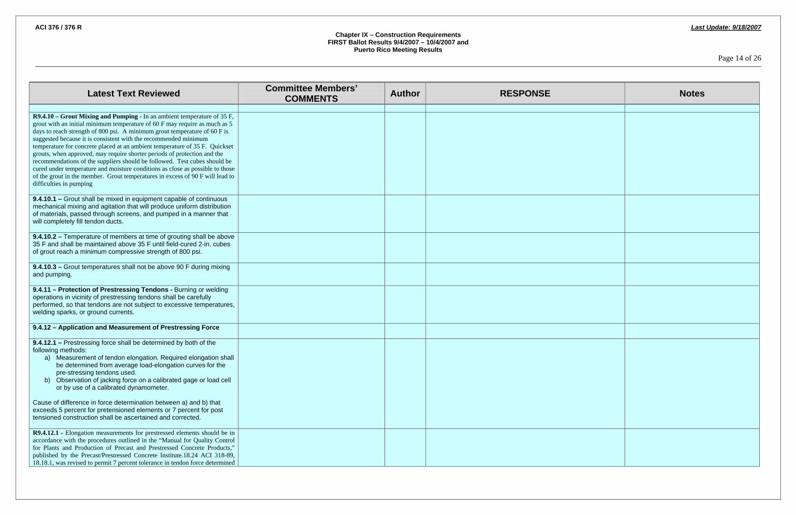
ACI 376 / 376 R Last Update: 9/18/2007 Chapter IX – Construction Requirements
FIRST Ballot Results 9/4/2007 – 10/4/2007 and Puerto Rico Meeting Results
Page 14 of 26
Latest Text Reviewed Committee Members’ COMMENTS Author RESPONSE Notes
R9.4.10 – Grout Mixing and Pumping - In an ambient temperature of 35 F, grout with an initial minimum temperature of 60 F may require as much as 5 days to reach strength of 800 psi. A minimum grout temperature of 60 F is suggested because it is consistent with the recommended minimum temperature for concrete placed at an ambient temperature of 35 F. Quickset grouts, when approved, may require shorter periods of protection and the recommendations of the suppliers should be followed. Test cubes should be cured under temperature and moisture conditions as close as possible to those of the grout in the member. Grout temperatures in excess of 90 F will lead to difficulties in pumping
9.4.10.1 – Grout shall be mixed in equipment capable of continuous mechanical mixing and agitation that will produce uniform distribution of materials, passed through screens, and pumped in a manner that will completely fill tendon ducts.
9.4.10.2 – Temperature of members at time of grouting shall be above 35 F and shall be maintained above 35 F until field-cured 2-in. cubes of grout reach a minimum compressive strength of 800 psi.
9.4.10.3 – Grout temperatures shall not be above 90 F during mixing and pumping.
9.4.11 – Protection of Prestressing Tendons - Burning or welding operations in vicinity of prestressing tendons shall be carefully performed, so that tendons are not subject to excessive temperatures, welding sparks, or ground currents.
9.4.12 – Application and Measurement of Prestressing Force
9.4.12.1 – Prestressing force shall be determined by both of the following methods:
a) Measurement of tendon elongation. Required elongation shall be determined from average load-elongation curves for the pre-stressing tendons used.
b) Observation of jacking force on a calibrated gage or load cell or by use of a calibrated dynamometer.
Cause of difference in force determination between a) and b) that exceeds 5 percent for pretensioned elements or 7 percent for post tensioned construction shall be ascertained and corrected.
R9.4.12.1 - Elongation measurements for prestressed elements should be in accordance with the procedures outlined in the “Manual for Quality Control for Plants and Production of Precast and Prestressed Concrete Products,” published by the Precast/Prestressed Concrete Institute.18.24 ACI 318-89, 18.18.1, was revised to permit 7 percent tolerance in tendon force determined

ACI 376 / 376 R Last Update: 9/18/2007 Chapter IX – Construction Requirements
FIRST Ballot Results 9/4/2007 – 10/4/2007 and Puerto Rico Meeting Results
Page 15 of 26
Latest Text Reviewed Committee Members’ COMMENTS Author RESPONSE Notes
by gage pressure and elongation measurements for post-tensioned construction. Elongation measurements for post-tensioned construction are affected by several factors that are less significant, or that do not exist, for pretensioned elements. The friction along post-tensioning tendons may be affected to varying degrees by placing tolerances and small irregularities in profile due to concrete placement. The friction coefficients between the tendons and the duct are also subject to variation. The 5 percent tolerance that has appeared in the code since ACI 318-63 was proposed by ACI-ASCE Committee 423 in 1958,18.3 and primarily reflected experience with production of pretensioned concrete elements. Since the tendons for pretensioned elements are usually stressed in air with minimal friction effects, the 5 percent tolerance for such elements was retained. 9.4.12.2 – Where transfer of force from bulkheads of pretensioning bed to concrete is accomplished by flame cutting prestressing tendons, cutting points and cutting sequence shall be predetermined to avoid undesired temporary stresses.
9.4.12.3 – Long lengths of exposed pretensioned strand shall be cut near the member to minimize shock to concrete.
9.4.12.4 – Total loss of prestress due to unreplaced broken tendons shall not exceed 2 percent of total prestress.
Late vote - Hjorteset Negative – To allow 2 percent unreplaced broken tendons is unacceptable. The committee should require that the contractor provides duct area and anchor wedges to replace at least 5% of required post-tensioning force. This is in line with segmental bridge construction.
R9.4.12.4 – This provision applies to all prestressed concrete members. For cast-in-place post-tensioned slab systems, a “member” should be that portion considered as an element in the design, such as the joist and effective slab width in one-way joist systems, or the column strip or middle strip in two-way flat plate systems.
9.4.13 – Prestressing Sequence
9.4.13.1 – The stressing sequence shall developed so as to minimize the amount of bending and shear stresses within the tank wall.
R9.4.13.1 – The stressing sequence is of significant importance for vertical cylindrical tanks due to the presence of openings and potential for large shear and bending. Therefore it is recommended that the vertical tendons are stressed prior to the hoop tendons to provide a level of pre compression to mitigate any vertical bending and shear. Secondly the hoop tendons should be stressed in such a manner that a prestressed distribution close to the

ACI 376 / 376 R Last Update: 9/18/2007 Chapter IX – Construction Requirements
FIRST Ballot Results 9/4/2007 – 10/4/2007 and Puerto Rico Meeting Results
Page 16 of 26
Latest Text Reviewed Committee Members’ COMMENTS Author RESPONSE Notes
design distribution is achieved. This is normally achieved through stressing the “even” tendons followed by the “odd” tendons (or vice versa). Additionally the design should specifically address the stressing sequence in the vicinity of the access opening.
9.4.13.2 requires the vertical tendons to be stressed prior to the horizontal tendons. This is not possible if a sliding joint or closing pour is employed in the wall design. Suggest moving this to the commentary as a recommended sequence.
Hoptay 9.4.13.2 – Vertical Tendons shall be stressed from prior to the horizontal tendons.
Change to read “…stressed prior to stressing the horizontal tendons.”
Hoff
R9.4.13.2 – The vertical tendons with the exception of those passing through the access opening should be stressed prior to the horizontals tendons.
Persuasive, amend text to Action add commentary to elude to stressing verts and horizontals 9.4.13.2 – Tendon sequencing shall be considered in the design of the wall and foundation. R.9.4.13.2 – Typically the vertical tendons with the exception of those passing through the access opening should be stressed prior to the horizontals tendons in order to attain maximum shear capacity and bending resistance. To Ballot Voted: Brannan, Mash, Hoptay, Howe, NKO, Hoff Negatives: 0 Abstentions: 0
Late vote – Hjorteset Comment – Remove the word “from”.
9.4.14 – Anchorages - Horizontal anchorages shall be qualified for the product service temperatures.
Should this go to Chapter 2?
R9.4.14 – Test results for specific anchorages should be obtained from post tensioning suppliers. Where records of tests cannot be furnished then scale testing of the proposed anchorages should be undertaken. Refer to FIP SR88/2 for additional information.
Should this go to Chapter 2?
9.5 – Winding of Prestressed Reinforcement-Wire or Strand
9.5.1 – Qualifications - The stressing system used shall be capable of consistently producing the specified stress at every point around the wall within a tolerance of + 7 % of the specified initial stress in each wire or strand, as specified in ACI 506.2.
R9.5.1 – Qualifications - Winding should be under the direction of a supervisor having technical knowledge of prestressing principles and experience with the winding system being used.
9.5.2 – Anchorage of Wire or Strand - Each coil of prestressed wire or strand shall be anchored to adjacent wire or strand, or to the wall surface, at sufficiently close intervals to minimize the loss of prestress in case of a break during wrapping. Anchoring clamps shall be removed wherever cover over the clamp in the completed structure would be less than 1 in.

ACI 376 / 376 R Last Update: 9/18/2007 Chapter IX – Construction Requirements
FIRST Ballot Results 9/4/2007 – 10/4/2007 and Puerto Rico Meeting Results
Page 17 of 26
Latest Text Reviewed Committee Members’ COMMENTS Author RESPONSE Notes
9.5.3 – Splicing of Wire or Strand - Ends of individual coils shall be joined by mechanical splicing devices qualified for service temperatures and shall develop the specified tensile strength of the reinforcement.
9.5.4 – Concrete or Shotcrete Strength - Concrete or shotcrete strength at time of stressing shall be at least 1.8 times the maximum initial stress due to prestressing in any wall section.
9.5.5 – Stress Measurement and Wire or Strand Winding Records
9.5.5.1 – A calibrated stress-recording device that can be readily recalibrated shall be used to determine stress levels in prestressed reinforcement throughout the wrapping process. At least one stress reading for every coil of wire or strand, or for each 1000 lb thereof, or for every foot of wall per layer, shall be taken after the prestressed reinforcement has been applied on the wall.
R9.5.5.1 – Readings of the force in the prestressed reinforcement inplace on the wall should be made when the wire or strand has reached ambient temperature. All such readings should be made on straight lengths of prestressed reinforcement. A written record of stress readings, including location and layer, should be maintained. This submission should be reviewed prior to acceptance of the work. Continuous electronic recordings taken on the wire or strand in a straight line between the stressing head and the wall may be used in place of the above when the system allows no loss of tension between the reading and final placement on the wall.
9.5.5.2 – The total initial prestress force measured on the wall per vertical foot of height shall be not less than the specified initial force in the locations indicated on the deign force diagram and not more than 5 percent greater than the specified force.
9.6 – Forming
9.6.1 – Slipforming – Slipforming is permitted. Unless otherwise indicated here, slipforming shall meet the requirements of ACI 347.
Rewrite: 9.6.1 Slipforming – Unless otherwise indicated, slip forming shall meet the requirements of ACI 347. Reason: ‘Slipforming is permitted’ is implied and I recommend removing this first statement.
Thompson Persuasive 9.6.1 – Slipforming – Slipforming is permitted. unless otherwise indicated here, slipforming shall meet the requirements of ACI 347. Considered an editorial change; Agreed: Brannan, Mash, Hoptay, Howe, NKO, Hoff

ACI 376 / 376 R Last Update: 9/18/2007 Chapter IX – Construction Requirements
FIRST Ballot Results 9/4/2007 – 10/4/2007 and Puerto Rico Meeting Results
Page 18 of 26
Latest Text Reviewed Committee Members’ COMMENTS Author RESPONSE Notes
Negatives: 0 Abstentions: 0
R9.6.1 – Slipforming is a desirable form of construction where a metallic vapor barrier is not used achieve liquid tightness due to the minimization of horizontal construction joints.
9.6.2 – Planning of Slipforming Operations – Since the slipform is a continuous procedure, planning shall be made for the supply of concrete, reinforcement and embedments so that the slipform can continue 24 hours per day without interference. Back up systems shall be incorporated including craneage, equipment for the slipform including additional pumps, hoses, jacks.
Should be 9.6.3 Hoff 9.6.2* – Planning of Slipforming Operations – Since the slipform is a continuous procedure, planning shall be made for the supply of concrete, reinforcement and embedments so that the slipform can continue 24 hours per day without interference. Back up systems shall be incorporated including craneage, equipment for the slipform including additional pumps, hoses, jacks.
Agreed numbering to be updated on next round
REMOVE the last four sentences in R9.62 - ‘Planning shall also include workmen requirements . . . . . Prior to pouring concrete in the forms detailed checklist for start-up slipform operations shall be completed’ Reason: When to use checklists is Means and Methods for contractors and should not be part of this document. The first paragraph is sufficient in my opinion.
Thompson R9.6.2 – Planning of Slipforming Operations – Slipforming operations involves a large number of people on a limited amount of space, working at different levels simultaneously. This requires significant attention to detail at the planning stage. Therefore, mock-ups and trails of heavy reinforced structural elements should be considered prior to construction. Planning shall also include workmen requirements, working tasks and responsibilities for the workmen and guiding of the slipform. Consideration should be made for the checking that enough equipment, spare parts and consumable goods are available. Along with this planning, back up solutions should be worked for all possible errors or faults that may occur. Prior to pouring concrete in the forms detailed checklist for start-up slipform operations shall be completed.
Should by R9.6.3 Add: For vertical slipforming, if the concrete slip is excessively delayed so that the hardened front of the concrete is approaching the top surface of the concrete, consideration should be given to using chemical retarders on the surface to delay the hardening of the surface. The unhardened binder on the surface can then be washed away, leaving a rough surface for the bonding when the slip is resumed.
Hoff
Action Hoff - Editorial comment and amend text Action Thompson non persuasive as the 4 sentences refer to more than just check lists alone. Include Thompsons text within commentary side R9.6.2* – Planning of Slipforming Operations – Slipforming operations involves a large number of people on a limited amount of space, working at different levels simultaneously. This requires significant attention to detail at the planning stage. Therefore, mock-ups and trails of heavy reinforced structural elements should be considered prior to construction. Prior to pouring concrete in the forms detailed checklist for start-up slipform operations should be completed. Planning should also include workmen requirements, working tasks and responsibilities for the workmen and guiding of the slipform. Consideration should be made for the checking that enough equipment, spare parts and consumable goods are available. Along with this planning, back up solutions should be worked for all possible errors or faults that may occur. Prior to pouring concrete in the forms detailed checklist for start-up slipform operations shall be completed. For vertical slipforming, if the concrete slip is excessively delayed so that the hardened front of the concrete is approaching the top surface of the concrete, consideration should be given to using chemical retarders on the surface to delay the hardening of the surface. The unhardened binder on the surface can then be washed away, leaving a rough surface for the
Agreed numbering to be updated on next round

ACI 376 / 376 R Last Update: 9/18/2007 Chapter IX – Construction Requirements
FIRST Ballot Results 9/4/2007 – 10/4/2007 and Puerto Rico Meeting Results
Page 19 of 26
Latest Text Reviewed Committee Members’ COMMENTS Author RESPONSE Notes
bonding when the slip is resumed Considered an editorial change; Agreed: Brannan, Mash, Hoptay, Howe, NKO, Hoff Negatives: 0 Abstentions: 0
9.6.2 – Casting and Consolidation – Casting and consolidation shall be in accordance with ACI 309R.
R9.6.2 – Vibrating too deeply will interfere with the setting in the layers below that might cause loose pieces of concrete to occur in the exposed surface underneath the form.
9.7 – Construction Joints
R9.7 – Construction Joints - Concrete surfaces upon or against which concrete is to be placed and to which new concrete is to adhere, that have become so rigid that the new concrete cannot be incorporated integrally by vibration with that previously placed are defined as construction joints. For precast construction the vertical joints should be pumped from bottom to top.
Awkward paragraph. Should begin as “Construction joints are defined as concrete surfaces upon…” and leave those words off of the end.
Hoff Persuasive editorial R9.7 – Construction Joints - Construction joints are defined as concrete surfaces upon or against which concrete is to be placed and to which new concrete is to adhere, that have become so rigid that the new concrete cannot be incorporated integrally by vibration with that previously placed are defined as construction joints. For precast construction the vertical joints should be pumped from bottom to top. Considered an editorial change; Agreed: Brannan, Mash, Hoptay, Howe, NKO, Hoff Negatives: 0 Abstentions: 0
9.7.1 – Location and type of construction joints shall be defined during the design stage.
R9.7.1 –For the integrity of the structure, it is important that all construction joints be carefully defined in construction documents and constructed as required. Any deviations should be approved by the design engineer. Type and details of unplanned joints should also be considered in the design stage.
9.7.2 – Surface of concrete construction joints shall be cleaned and laitance removed.
Rewrite: 9.7.2 – The surface of construction joints shall be cleaned with all laitance removed and a bonding agent applied prior to placement of new concrete. Reason: A bonding agent at all construction joints should be used for RLG tanks in my opinion.
Thompson Non persuasive due to potential constructability issues. Maintain original text Agreed: Brannan, Mash, Hoptay, Howe, NKO, Hoff Negatives: 0 Abstentions: 0

ACI 376 / 376 R Last Update: 9/18/2007 Chapter IX – Construction Requirements
FIRST Ballot Results 9/4/2007 – 10/4/2007 and Puerto Rico Meeting Results
Page 20 of 26
Latest Text Reviewed Committee Members’ COMMENTS Author RESPONSE Notes
R9.7.2 – The surfaces of concrete at all construction joints should be prepared as called for in ACI 301. Where reliance is placed on concrete alone for leak tightness then the surface of construction joints should be roughened to an amplitude 1/4 in. The final roughened surface shall be clean and all laitance and loose material removed prior to inspection. Prior to placement of new concrete, the final cleaning should be carried out using high-pressure water.
Change “1/4 in.” to “of a minimum of at least ¼ in.” Hoff Persuasive, amend text to R9.7.2 – The surfaces of concrete at all construction joints should be prepared as called for in ACI 301. Where reliance is placed on concrete alone for leak tightness then the surface of construction joints should be roughened to an a minimum amplitude 1/4 in. The final roughened surface shall be clean and all laitance and loose material removed prior to inspection. Prior to placement of new concrete, the final cleaning should be carried out using high-pressure water. Agreed: Brannan, Mash, Hoptay, Howe, NKO, Hoff Negatives: 0 Abstentions: 0
9.7.3 – Immediately before new concrete is placed, all construction joints shall be wetted to be in a saturated surface dry condition.
R9.7.3 – Cleaning with water prior to pouring of concrete avoids the drawing of moisture from the concrete mix and weakening/honeycombing of the joint. Freestanding water should be removed prior to commencement of concreting operations. The requirements of the 1977 ACI 318 code for the use of neat cement on vertical joints have been removed, since it is rarely practical and can be detrimental where deep forms and steel congestion prevent proper access. Often wet blasting and other procedures are more appropriate. Since the code sets only minimum standards the engineer may have to specify special procedures if conditions warrant. The degree to which mortar batches are needed at the start of concrete placement depend on concrete proportions, congestion of steel, vibrator access, and other factors.
9.7.4 – Construction joints shall be so made and located as not to impair the strength of the structure. Provision shall be made for transfer of shear and other forces through construction joints. See ACI 350 paragraph 11.7.9.
R9.7.4 –Construction joints should be located where they will cause the least weakness in the structure. When shear due to gravity load is not significant, as is usually the case in the middle of the span of flexural members, a simple vertical joint may be adequate. Lateral force design may require special design treatment of construction joints. Shear keys, intermittent shear keys, diagonal dowels, or the shear transfer method of ACI 350 paragraph 11.7 may be used whenever a force transfer is required.
ACI 376 / 376 R Last Update: 9/18/2007 Chapter IX – Construction Requirements
FIRST Ballot Results 9/4/2007 – 10/4/2007 and Puerto Rico Meeting Results
Page 21 of 26
Latest Text Reviewed Committee Members’ COMMENTS Author RESPONSE Notes
9.8 – Design of Formwork – Formwork shall be designed and made as per ACI 350 Chapter VI.
9.10 – Concrete Emdedments – Concrete embedments should be considered and detailed during the design stage. Requirements of ACI 350 shall be satisfied.

ACI 376 / 376 R Last Update: 9/19/2007 CHAPTER 10
Results of Ballot 9/14/07 to 10/14/07 & Results of P.R. Meeting Page 1 of 7
CHAPTER 10 – COMMISSIONING AND DECOMISSIONING CRITERIA
Approved Sections Section Approved with Comments to be resolved Negative Vote Section currently voted on Ongoing work
FINAL VOTES AS OF 10/15/07 (Ballot Closed on 10/14/07)
& Puerto Rico Meeting Results
CODE Vote Comments Author RESPONSE Notes A general comment for this chapter: Is the committee concerned that ACI may not to take on the responsibility for process or metal tank issues?
Hoptay Comment withdrawn by Hoptay. See P.R. meeting minutes for verification
Please verify that final tightening of anchorage is always befor filling with water. I believe steel tank anchor straps are tightened after filling with water and before pneumatic testing.
Pawski
Anchorage is tightened after filling with water but before pneumatic pressure is applied.
Howe
Unsure how pneumatic testing will induce load into the anchors of the inner tank? Suggest deletion of the same?
Mash
10.2.x - Anchorage - Final tightening of anchorage that requires tightening of individual anchors, shall be performed prior to start of both (a) the pneumatic testing and (b) filling of tank with water, if hydrostatic testing is performed. Anchorage capacity shall be tested by pressurizing the empty tank to the design pressure.
Testing the anchor by pressurizing the tank seems to be redundant. The load tested will be much less than the requirement of the anchor in a seismic event.
Holleyoak
TO BE COMPLETED 10.2.x - Anchorage – Where anchorage is provided that requires tightening of individual anchors, tightening shall be performed: (a) prior to the pneumatic testing, and (b) during the hydrotest, with the tank filled at the
maximum water level. Anchorage capacity shall be tested by pressurizing the empty tank to the design pressure. NOTE: Recognize difference between: primary and secondary container, anchors and straps, anchor bolts and other anchor types.
There are a fair number of ASTM's with pitting. The one you most likely want is ASTM G46 Standard Guide for Evaluating Pitting Corrosion
Brannan 10.2.2 – Quality of Test Water - The test water shall be clean and may include suitable corrosion inhibitors. Use of clean seawater for hydro testing of primary lined or unlined concrete or metal containers is permitted, but at a minimum the following criteria shall be met whether using potable, brackish or seawater for the hydrotest:
a. Seawater shall be filtered to remove solids and prohibit the introduction of significant quantities of marine life and debris into the tank.
b. No hydrogen sulfide is allowed in water.. c. Water pH shall be between 6 and 8.3. d. Water temperature shall be below 120°F (49°C).
NEGATIVE Will E-mail comments for10.2.2 and R10.2.2 directly to Nevin As of 10/20/2007 - NO COMMENTS received by the Voting Deadline & Puerto Rico Meeting.
Thompson
No comments were received from Thompson by the Voting Deadline & Puerto Rico Meeting. Brannan’s comment has been found convincing. The comment is addressed by introducing R10.2.2 below. R10.2.2 - ASTM G46 “Standard Guide for Evaluating Pitting Corrosion.” Should be used for evaluating the effects or potential for pitting corrosion.
Consider moving parts or all into the commentary. Some provisions seem to be written like recommendations. Revisit compatibility with API 620 Appendix Q or S – consider the case of metal plates, liners or other metal components. Possibly divide the section into one for concrete and the other for metal components.

ACI 376 / 376 R Last Update: 9/19/2007 CHAPTER 10
Results of Ballot 9/14/07 to 10/14/07 & Results of P.R. Meeting Page 2 of 7
CODE Vote Comments Author RESPONSE Notes e. For austenitic stainless steel tanks, the chloride
content of the water shall be below 50 parts per million.
f. For aluminum tanks, the mercury content of the water shall be less than 0.005 parts per million, and the copper content shall be less than 0.02 parts per million.
g. All 9% nickel, stainless steel or aluminum surfaces that will come in contact with the seawater shall be adequately protected against corrosion. All weld seams and associated heat-affected zones (HAZ’s) shall be cleaned/prepared and coated with an approved primer after completion of all required NDT inspections. Previously-primed abraded areas shall also be repaired and re-primed.
h. All weld seams and associated heat-affected zones (HAZ’s) shall be cleaned/prepared and coated with an approved primer after completion of all required NDT inspections. Previously-primed abraded areas shall also be repaired and re-primed.
i. All internal pump columns, stilling wells, standpipes, internal piping, fittings, attachments, guides, etc. shall be 9% nickel or an approved high nickel alloy, except that in case when 9% nickel or high nickel alloys are not available, stainless steel shall be permitted to be used subject to the following limitation: The stainless steel components shall be completely coated on all exposed surfaces with an approved coating, and all inside surfaces shall be sealed during the entire hydrotest cycle. Alternatively, stainless steel components shall be permitted to be installed after the hydrotest.
j. The 9% nickel, stainless, or aluminum metal primer shall have proven adhesive performance characteristics suitable for cyclic exposures to cryogenic conditions. Any primer that cannot be demonstrated to have the required adhesion performance shall be stripped after the hydrotest.
k. Seawater sampling, corrosion, and pitting tests shall be conducted using the actual seawater from the site prior to hydrotest.
l. For metal tanks, or metal components of concrete tanks, the entire surface of the inner tank or component, and all internals exposed to seawater shall be high-pressure spray washed with potable water immediately after the hydrotest, to remove any sodium chloride residue from the metal surfaces before these surfaces dry. All surfaces of the inner tank walls and floor shall be brush scrubbed after the initial high pressure spray wash. A second high pressure rinse with potable water shall be applied after the brushing operation.
m. All surfaces of the primary concrete tank exposed to seawater shall be spray-saturated to a

ACI 376 / 376 R Last Update: 9/19/2007 CHAPTER 10
Results of Ballot 9/14/07 to 10/14/07 & Results of P.R. Meeting Page 3 of 7
CODE Vote Comments Author RESPONSE Notes saturated-surface-dry condition using with fresh water immediately prior to the hydrotest.
n. For concrete tanks all surfaces of the inner tank walls and floor shall be high-pressure spray washed with potable water immediately after the hydrotest.
o. Cleaning and drying of the tank shall be in accordance with prescribed approved procedures. All surfaces of the inner tank walls and floor shall be washed with clean, suitable water with less than 250 parts per million of chlorides. Washing shall be performed with a high-pressure (>2500 psi) spray. The tank shall be dried immediately after washing.
p. The seawater hydrotest period shall not exceed 30 days. The hydrotest period is defined as fill, test, empty, wash, and clean/dry time inclusive.
q. The surface shall be visually inspected for signs of corrosion, pitting, or degradation.
R10.2.2 - ASTM G46 “Standard Guide for Evaluating Pitting
Corrosion.” Should be used for evaluating the effects or potential for pitting corrosion.
R10.2.2 – Quality of Test Water - The USEPA Drinking Water Standard has the following limits:
• Chloride limit is less than 250 ppm or mg/l • Copper limit is less than 1 ppm or mg/l • Mercury limit is less than 0.002 ppm or mg/l
Corrosion inhibitors may impact disposal options of test water and should consider local environmental regulations for discharge. The use of seawater as the liquid for the hydrotest in RLG tanks poses a unique set of challenges. Brackish or seawater contains substances that can cause corrosion during the hydrotest if proper precautions are not taken. Furthermore:
(e) It should be noted that 50ppm is very difficult to achieve.
(g) The following techniques may be used to provide adequate corrosion protection: prime coating with an approved primer, impressed current cathodic protection, etc. The primer used for coating shall have proven adhesive performance characteristics suitable for cyclic exposures to cryogenic conditions or must be stripped off after the hydrotest. If hydro test water is left in the tank for less than three weeks, 9% Nickel surfaces may be left bare, provided they are thoroughly washed and dried after the hydro test.
(p) In some instances the hydro test water will be maintained in the tank for an extended period to consolidate the soil. It may also be left in the tank to
NEGATIVE Will E-mail comments for10.2.2 and R10.2.2 directly to Nevin As of 10/20/2007 - NO COMMENTS received by the Voting Deadline & Puerto Rico Meeting.
Thompson No comments were received from Thompson by the Voting Deadline & Puerto Rico Meeting.

ACI 376 / 376 R Last Update: 9/19/2007 CHAPTER 10
Results of Ballot 9/14/07 to 10/14/07 & Results of P.R. Meeting Page 4 of 7
CODE Vote Comments Author RESPONSE Notes wait for the hydro test of another tank. In these instances, the engineer shall make special provisions.
If settlement monitoring shows a deviation of pre-calculation values of more than 15% the design engineer shall be informed immediately.
Douglas 10.2.xx – The tank foundations shall be monitored and recorded for settlement before, during, and after the hydrotest per Chapter 8 (Foundations) of this document.
Include Additional tet as follows As a minimum settlement data including benchmarking or the inclinometers should be carried out at the following construction milestones; • On completion of the base slab and prior to commencement of the wall construction. • On completion of the walls, prior to the commencement of the roof. • On completion of the roof construction • Prior to, during and after hydrotest. • Prior to cool down
Mash
Change is more than editorial 10.2.xx – The tank foundations shall be monitored and recorded for settlement before, during, and after the hydrotest and during commissioning, as per Chapter 8 (Foundations) of this document. When settlement monitoring exceeds predefined values the design engineer shall be notified immediately. To be balloted. Approvedd: Brannan, Hoptay, NKO, Pawski, Hoff, Wu Negative: 0 Abstained: 0
Similar Addressed in Chapter 8. Coordinate.
R10.2.xx - Baseline settlement data must be collected during benchmarking. Additionally, at a minimum, settlement data must be collected at the following construction milestones:
1) Completion of the base slab, prior to commencement of the wall construction,
2) Completion of the walls, prior to the commencement of the roof construction,
3) Completion of the roof construction, 4) Prior to, during, and after the hydrotest, 5) At the start of cool down.
Inclinometers, if installed, should be surveyed at the same time as defined above. To be balloted. Approved: Brannan, Hoptay, NKO, Pawski, Hoff, Wu Negative: 0 Abstained: 0
Editorial: Add a commentary section R 10.2.*** During pressure and vacuum relief valve testing the pressure and vacuum should be closely monitored for overpressure and excess vacuum. During hydrotest, the potential for overpressure and excess vacuum is high. If vacuum is possible, the vacuum system should be capable of providing dry gas (nitrogen) instead of humid air. Humid air has the potential of ‘ice plugging’. Air could potentially create a flammable atmosphere within the tank.”
Brannan Brannan’s comment was addressed by adding the commentary. The text for 10.2.xxx remains unchanged
10.3.x 10.2.xxx – Pressure and Vacuum Relief Testing – Proper functioning of all pressure and vacuum relief valves and devices shall be confirmed by:
• Check pressure relief by increasing pressure in the vapor space.
• Check vacuum relief by creating a vacuum with a vacuum pump, or alternatively, by partially withdrawing water from the tank.
What is wrong with conventional testing of relief & vacuum breaker valves with test gas applied to the pressure sensing line and set point of controls calibrated with a dead weight tester. This sounds over the top. What are we checking for, a plugged line?
Hatfield 10.3.x 10.2.xxx Hatfield’s comment has not been found convincing. The assumed bench testing proposed by Hatefield as the only required testing is insufficient. The purpose of this requirement is to assure in-place testing of the entire system.

ACI 376 / 376 R Last Update: 9/19/2007 CHAPTER 10
Results of Ballot 9/14/07 to 10/14/07 & Results of P.R. Meeting Page 5 of 7
CODE Vote Comments Author RESPONSE Notes To be balloted. Approved: Brannan, Hoptay, NKO, Pawski, Wu Negative: 0 Abstained: 0
R10.3.X – Pressure and Vacuum Relief Testing - During pressure and vacuum relief valve testing, pressure / vacuum levels should be closely monitored for overpressure and excess vacuum. A fail-safe system (e.g., U-tube) should be provided to prevent excessive development of pressure or vacuum. To be balloted. Approved: Brannan, Hoptay, NKO, Pawski, Wu Negative: 0 Abstained: 0
Editorial: spelling of “tank” Brannan Change "tan" to "tank" Berner Change "tan" to "tank". Hoff Typo tan=tank Holleyoak This comment needs some "word smithing" to better explain. Top and bottom nozzles are the only way to fill the tank, there is nothing else. Therefore, the choice of top or bottom fill is based on the density of the liquid currently in the tank as compared to the liquid being added. If low density liquid exists in the tank, and heavier density liquid is being added, the top fill nozzle should be used. If higher density liquid exists in the tank as compared to the liquid being added, the bottom fill nozzle should be used to promote mixing.
Hatfield
“mixing in tank” Rajan
Pawski’s comment is introduced as an editorial change. The paragraph is changed to the following to address Hatfield’s comment. Other comments have also been addressed R10.7.1 - The choice of top or bottom fill is based on the density of the liquid currently in the tank as compared to the liquid being added. This is only an editorial change. Agreed – Voting: Brannan, Hoptay, NKO, Pawski, Wu Agreed – non-voting Ballard Disagreements: 0 Abstentions: 0
R10.7.1 - To avoid tank stratification and to promote mixing in the tan, top and bottom fill nozzles should be used when filling the tank with the product.
This is repeat of the provisions. Pawski The negative vote has been withdrawn – see PR minutes for confirmation. It was dealt as an editorial comment.
Editorial: Change “shall” to “should”. Add: “Splash plates and distribution piping should be checked to ensure product cannot impinge on the walls or roof platform. Check to ensure distribution piping should discharge product in each quadrant of the tank to reduce the risk of spot cooling.”
Brannan Brannan’s comment is withdrawn as it has been answered in the Code section. See PR minutes for confirmation.
Change "shall" to "should". Hoff Item removed. The comment is no longer relevant. Add "and removal of entrained vapor." Hoptay Item removed. The comment is no longer relevant for this
section. The comment introduced to 10.7.2. Splash plate shall be designed so that the LNG is directed into the primary tank and does not allow LNG to impact the suspended deck or overtop the tank.
Mash Item removed. The comment is no longer relevant to this section. The comment introduced to 10.7.2.
A splash plate is a design feature for permanent installation and should be in the design chapter, not commissioning. A splash plate is used both during commissioning and routine operations.
Hatfield Item removed. The comment is no longer relevant.
R10.7.2 – A splash plate on the nozzle outlet shall be used for the top fill in order to provide a distributed discharge of the product.
This is mostly a repeat of the provisions. Pawski Pawski’s negative vote has been withdrawn – see PR minutes for confirmation. It was dealt as an editorial comment.
Revisit Hatfield’s comment regarding moving the comment to a different section. Consider moving it to detailing section – chapter 7 “A splash plate is a design feature for permanent installation and should be in the design chapter, not commissioning. A splash plate is used both during commissioning and routine operations.”

ACI 376 / 376 R Last Update: 9/19/2007 CHAPTER 10
Results of Ballot 9/14/07 to 10/14/07 & Results of P.R. Meeting Page 6 of 7
CODE Vote Comments Author RESPONSE Notes SECTION REMOVED Pawski’s editorial comment was found convincing and has been introduced as an editorial change. The commentary is redundant and therefore is removed. This is only an editorial change Agreed – Voting: Brannan, Hoptay, NKO, Pawski, Wu Agreed – non-voting Ballard Disagreements: 0 Abstentions: 0
10.7.2 - Top fill requires a splash plate on the nozzle outlet to provide a distributed discharge of liquid and removal of entrained vapor. Liquid shall not impinge on walls, splash upward to impact the suspended deck, nor enter the insulated space above or around the inner tank roof. The change is editorial.
Editorial: Add; “Temperatures and pressures near nozzles should be monitored to avoid too rapid cooling and possible overpressure.”
Brannan Brannan’s comment has been withdrawn after committee’s discussion. See PR Minutes for confirmation
"Liquid gas" does not seem to sound right. How about just "liquid" or "LNG"
Rajan Rajan’s comment is convincing but applies to the Code side since this item R10.7.3 has been removed. See 10.7.3. This is only an editorial change. Agreed – Voting: Brannan, Hoptay, NKO, Pawski, Wu Agreed – non-voting Ballard Disagreements: 0 Abstentions: 0
R10.7.3 - Liquid gas that enters the tank should be flashed to obtain the same pressure as the tank.
This is repeat of the provisions. Pawski SECTION REMOVED The negative vote has been withdrawn – see PR minutes for confirmation. It was dealt as an editorial comment. Pawski’s comment is introduced as an editorial change. The commentary is redundant and therefore is removed. This is only an editorial change Agreed – Voting: Brannan, Hoptay, NKO, Pawski, Wu Agreed – non-voting Ballard Disagreements: 0 Abstentions: 0
10.7.3 - Liquiefied gas that enters the tank should be flashed to obtain the same pressure as the tank. Rajan’s comment on R10.7.3 applies to 10.7.3 and has been introduced accordingly. This is only an editorial change. Agreed – Voting: Brannan, Hoptay, NKO, Pawski, Wu Agreed – non-voting Ballard Disagreements: 0 Abstentions: 0

ACI 376 / 376 R Last Update: 9/19/2007 CHAPTER 10
Results of Ballot 9/14/07 to 10/14/07 & Results of P.R. Meeting Page 7 of 7
CODE Vote Comments Author RESPONSE Notes How would the operator know if stratification is occurring? Allen SECTION REMOVED
Item removed. The comment is no longer relevant Agreed – Voting: Brannan, Hoptay, NKO, Pawski, Wu Agreed – non-voting Ballard Disagreements: 0 Abstentions: 0
Recirculation is used both during commissioning and routine operations to prevent stratification.
Hatfield Item removed. The comment is no longer relevant Agreed – Voting: Brannan, Hoptay, NKO, Pawski, Wu Agreed – non-voting Ballard Disagreements: 0 Abstentions: 0
R10.7.4 - Tank pumps should be used for recirculation if stratification or an unsafe density mixture occurs.
This is repeat of the provisions. Pawski The negative vote has been withdrawn – see PR minutes for confirmation. It was dealt as an editorial comment. Pawski’s comment is introduced as an editorial change. The commentary is redundant and therefore is removed. This is only an editorial change Agreed – Voting: Brannan, Hoptay, NKO, Pawski, Wu Agreed – non-voting Ballard Disagreements: 0 Abstentions: 0
Check with Nick if to be moved to commentary
Change "shall" to "should" Hoff R10.7.5 - Top and bottom fill lines shall have in-line flow meters for monitoring of tank fill rates to avoid excess flow and high vibration of fill lines and nozzles during fill operations.
This is repeat of the provisions. Pawski
SECTION REMOVED The negative vote has been withdrawn – see PR minutes for confirmation. It was dealt as an editorial comment. Pawski’s comment is introduced as an editorial change. The commentary is redundant and therefore is removed. This is only an editorial change Agreed – Voting: Brannan, Hoptay, NKO, Pawski, Wu Agreed – non-voting Ballard Disagreements: 0 Abstentions: 0
Copyright © 2022 FDOKUMEN