Acceptance Testing Converted CR to DR Systems ... - AAPM
24
3/22/2019 1 The following report is proprietary information and constitutes trade secrets of The MetroHealth System and may not be disclosed in whole or part to any external parties without the express consent of The MetroHealth System. This document is intended to be used internally for The MetroHealth System discussion. Acceptance Testing Converted CR to DR Systems Ryan Fisher, PhD CR Photostimulable phosphor (PSP) screen absorbs x-rays and traps energy Plate run through processor where laser light releases stored energy to form digital image Computed Radiography (CR) vs Digital Radiography (DR) DR (Indirect) Scintillator absorbs x-rays, producing light that is immediately read by flat panel Thin-Film-Transistor (TFT) array, forming the digital image
-
Upload
khangminh22 -
Category
Documents
-
view
1 -
download
0
Transcript of Acceptance Testing Converted CR to DR Systems ... - AAPM
3/22/2019
1
The following report is proprietary information and constitutes trade secrets of The MetroHealth System and may not be disclosed in whole or part to any
external parties without the express consent of The MetroHealth System. This document is intended to be used internally for The MetroHealth System
discussion.
Acceptance Testing Converted CR to DR Systems
Ryan Fisher, PhD
CR
Photostimulable phosphor (PSP) screen absorbs x-rays and traps energy
Plate run through processor where laser light releases stored energy to form digital image
Computed Radiography (CR) vs Digital Radiography (DR)
DR (Indirect)
Scintillator absorbs x-rays, producing light that is immediately read by flat panel Thin-Film-Transistor (TFT) array, forming the digital image
3/22/2019
2
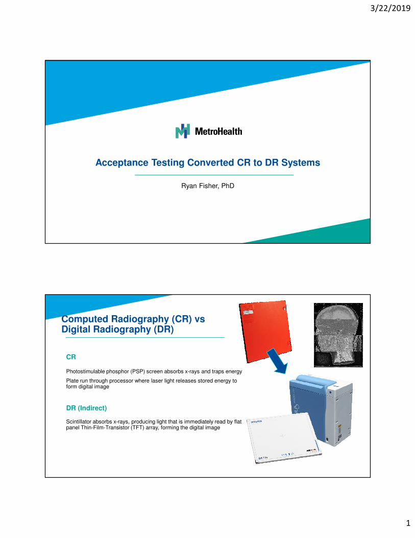
DR Pros DR Cons
Faster image acquisition & improved throughput
Potential for dose reduction
Remove large bulky CR readers
Replace multiple cassettes with a single digital panel
Expensive
Single point of failure
Need panel for every room
Battery life issues
Wireless connectivity issues
Potential practice limitations
Why Transition from CR to DR?
CMS Payment Reduction
p. 777

3/22/2019
3
CMS Payment Reduction
• As of Jan 1, 2018: 7% reduction in payments for imaging services taken using computed radiography.
• As of Jan 1, 2023: 10% reduction in payments
• As of 2017: 20% reduction for film
agfa.com
DR Panel Retrofit of Existing Room
• Pros
• Cheaper than a full DR suite
• Quick installation with minimal down time
• Cons
• Another monitor on the counter
• Likely no generator integration
• Other quirks – bucky tray reset etc.
DR Transition Options
3/22/2019
4
Experiences with Large Scale DR Panel Installation Project
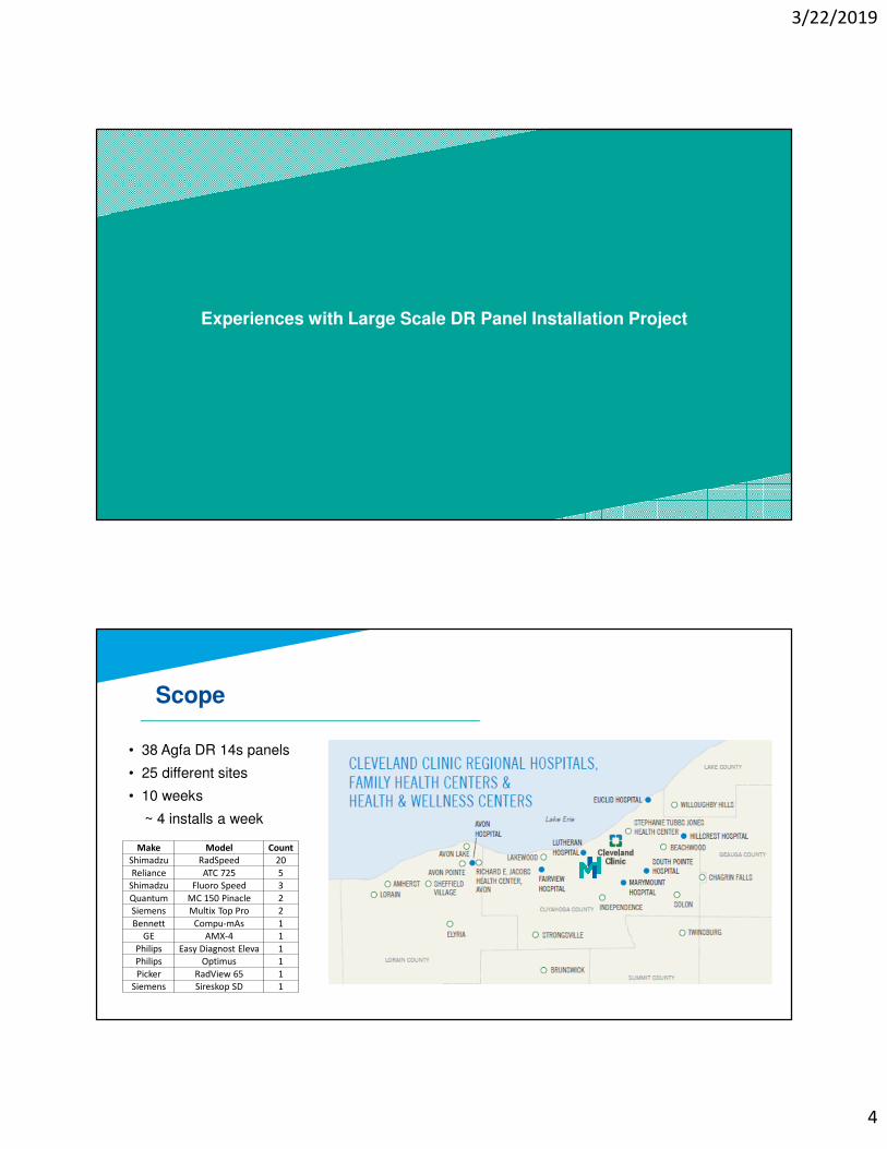
Scope
• 38 Agfa DR 14s panels
• 25 different sites
• 10 weeks
~ 4 installs a week
Make Model Count
Shimadzu RadSpeed 20
Reliance ATC 725 5
Shimadzu Fluoro Speed 3
Quantum MC 150 Pinacle 2
Siemens Multix Top Pro 2
Bennett Compu-mAs 1
GE AMX-4 1
Philips Easy Diagnost Eleva 1
Philips Optimus 1
Picker RadView 65 1
Siemens Sireskop SD 1
3/22/2019
5
Set yourself up for success
• Make Sure all appropriate people are in the loop
• Medical Physics
• Radiology admin
• Site managers & technologists
• Appropriate Radiologists
• IT / Informatics
• Panel vendor installation team
• Panel vendor applications specialists
• Field service engineers for the x-ray equipment
Notes on DR Installation Planning
Set yourself up for success
Site selection
• First rooms will likely go the slowest as you work the kinks out of your process
• Busy standalone ED room with no other imaging options is not a good test site
• Helps to have overflow available if things go south
• Type of x-ray room – will determine who else needs to be on-site and how difficult some steps will be
• Patient volume
• Types of exams in the room/site
• Radiologists on site?
Notes on DR Installation Planning
3/22/2019
6
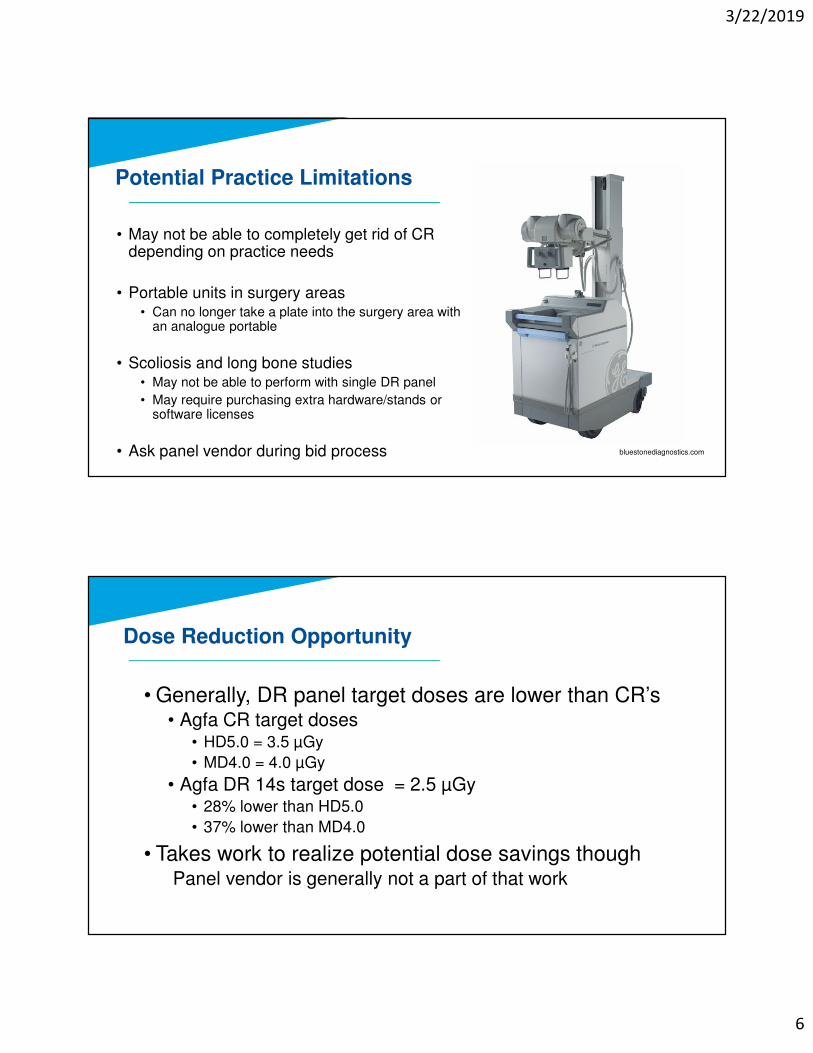
Potential Practice Limitations
• May not be able to completely get rid of CR depending on practice needs
• Portable units in surgery areas• Can no longer take a plate into the surgery area with
an analogue portable
• Scoliosis and long bone studies• May not be able to perform with single DR panel
• May require purchasing extra hardware/stands or software licenses
• Ask panel vendor during bid process bluestonediagnostics.com
Dose Reduction Opportunity
• Generally, DR panel target doses are lower than CR’s • Agfa CR target doses
• HD5.0 = 3.5 µGy
• MD4.0 = 4.0 µGy
• Agfa DR 14s target dose = 2.5 µGy• 28% lower than HD5.0
• 37% lower than MD4.0
• Takes work to realize potential dose savings thoughPanel vendor is generally not a part of that work
3/22/2019
7
Technique Standardization Opportunity
• Health system had expanded rapidly in recent years~ 200 fixed general radiography rooms
~ 50 physical locations
Large portion was Agfa CR based but not as much effort into standardizing techniques and would have liked
• Retrofit process gave chance to focus on techniques and to standardize practice
• Standardize Target Exposure Indexes (TEI) as well
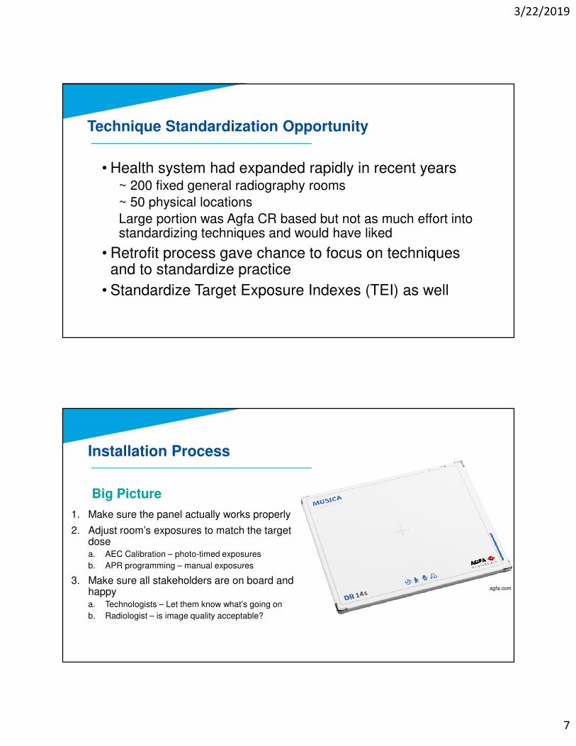
Installation Process
1. Make sure the panel actually works properly
2. Adjust room’s exposures to match the target dosea. AEC Calibration – photo-timed exposures
b. APR programming – manual exposures
3. Make sure all stakeholders are on board and happya. Technologists – Let them know what’s going on
b. Radiologist – is image quality acceptable?
agfa.com
Big Picture
3/22/2019
8
VENDOR INSTALLATION
Parties Involved
Panel Vendor
Hospital IT/Informatics
Site Managers & Technologists
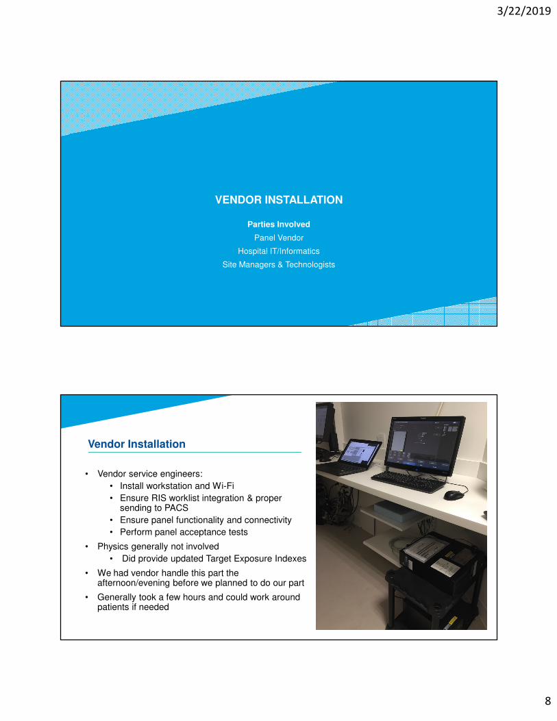
• Vendor service engineers:
• Install workstation and Wi-Fi
• Ensure RIS worklist integration & proper sending to PACS
• Ensure panel functionality and connectivity
• Perform panel acceptance tests
• Physics generally not involved
• Did provide updated Target Exposure Indexes
• We had vendor handle this part the afternoon/evening before we planned to do our part
• Generally took a few hours and could work around patients if needed
Vendor Installation
3/22/2019
9
Physics Panel Acceptance Testing
Parties Involved
Medical Physics
Site Managers & Technologists
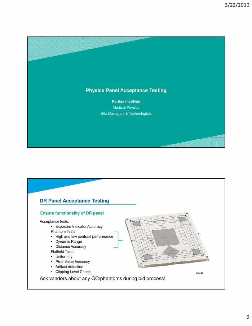
Ensure functionality of DR panel
Acceptance tests:
• Exposure Indicator Accuracy
Phantom Tests
• High and low contrast performance
• Dynamic Range
• Distance Accuracy
Flatfield Tests
• Uniformity
• Pixel Value Accuracy
• Artifact detection
• Clipping Level Check
Ask vendors about any QC/phantoms during bid process!
DR Panel Acceptance Testing
ptw.de
3/22/2019
10
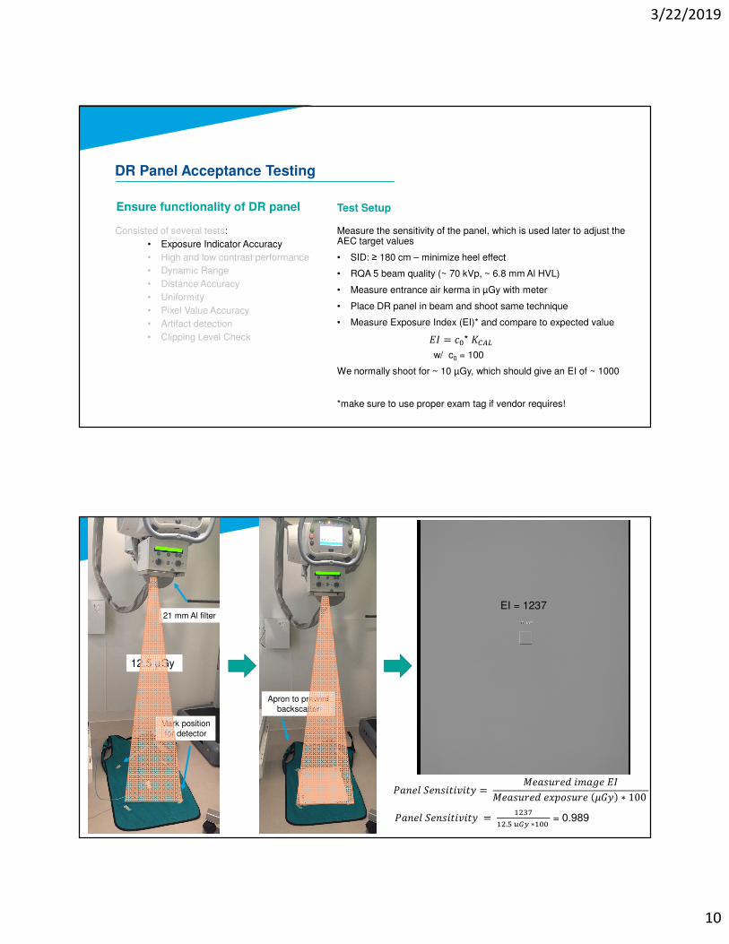
Ensure functionality of DR panel
Measure the sensitivity of the panel, which is used later to adjust the AEC target values
• SID: ≥ 180 cm – minimize heel effect
• RQA 5 beam quality (~ 70 kVp, ~ 6.8 mm Al HVL)
• Measure entrance air kerma in µGy with meter
• Place DR panel in beam and shoot same technique
• Measure Exposure Index (EI)* and compare to expected value
w/ c0 = 100
We normally shoot for ~ 10 µGy, which should give an EI of ~ 1000
*make sure to use proper exam tag if vendor requires!
DR Panel Acceptance Testing
Consisted of several tests:
• Exposure Indicator Accuracy
• High and low contrast performance
• Dynamic Range
• Distance Accuracy
• Uniformity
• Pixel Value Accuracy
• Artifact detection
• Clipping Level Check �� = ��* ���
Test Setup
�� �� ��������� = � ���� ����� ��
� ���� � ������ � � ∗ 100
�� �� ��������� = $%&'
$%.)*+,∗$��= 0.989
21 mm Al filter
Mark position
for detector
Apron to prevent
backscatter
12.5 µGy
EI = 1237
3/22/2019
11
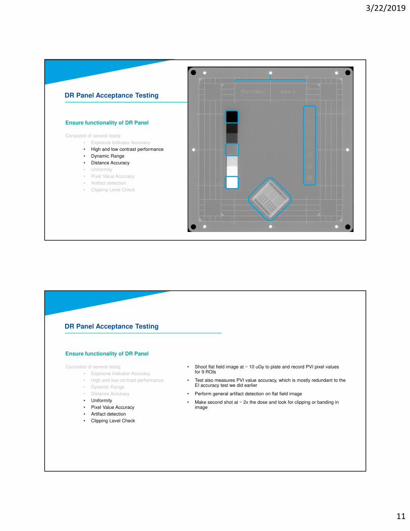
Ensure functionality of DR Panel
DR Panel Acceptance Testing
Consisted of several tests:
• Exposure Indicator Accuracy
• High and low contrast performance
• Dynamic Range
• Distance Accuracy
• Uniformity
• Pixel Value Accuracy
• Artifact detection
• Clipping Level Check
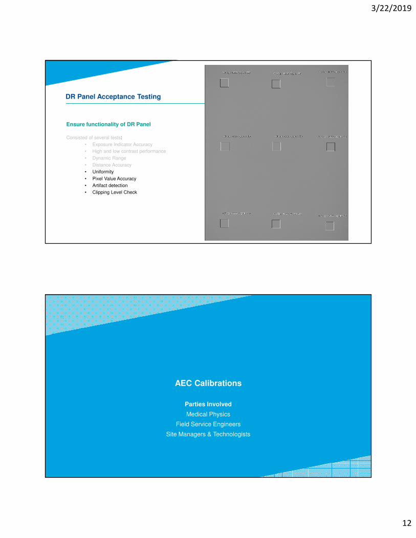
Ensure functionality of DR Panel
DR Panel Acceptance Testing
Consisted of several tests:
• Exposure Indicator Accuracy
• High and low contrast performance
• Dynamic Range
• Distance Accuracy
• Uniformity
• Pixel Value Accuracy
• Artifact detection
• Clipping Level Check
• Shoot flat field image at ~ 10 uGy to plate and record PVI pixel values for 9 ROIs
• Test also measures PVI value accuracy, which is mostly redundant to the EI accuracy test we did earlier
• Perform general artifact detection on flat field image
• Make second shot at ~ 2x the dose and look for clipping or banding in image
3/22/2019
12
Ensure functionality of DR Panel
DR Panel Acceptance Testing
Consisted of several tests:
• Exposure Indicator Accuracy
• High and low contrast performance
• Dynamic Range
• Distance Accuracy
• Uniformity
• Pixel Value Accuracy
• Artifact detection
• Clipping Level Check
AEC Calibrations
Parties Involved
Medical Physics
Field Service Engineers
Site Managers & Technologists
3/22/2019
13
Adjust photo-timed doses to new panel
• Big picture: Adjust the AEC cutoff level to the entrance dose requirements of DR panel
(obviously need to know what the target dose for the detector is)
• This likely means lowering the cutoff value from whatever was in place for CR
• Vendor may have their own procedure
• Shimadzu had a calibration process w/ increasing acrylic thickness at 60, 80, 100, & 120 kVp
• Otherwise, several options for calibration set up:
• Phantom - Acrylic @ bucky vs Al or Cu @ the collimator
• Wall board - kVp and SID options
AEC Calibrations
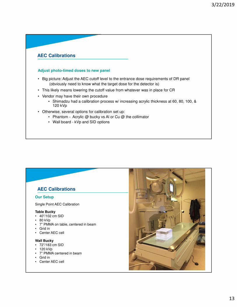
Our Setup
Single Point AEC Calibration
Table Bucky• 40”/102 cm SID• 80 kVp• 7” PMMA on table, centered in beam• Grid in• Center AEC cell
Wall Bucky• 72”/183 cm SID• 120 kVp• 7” PMMA centered in beam• Grid in• Center AEC cell
AEC Calibrations
3/22/2019
14
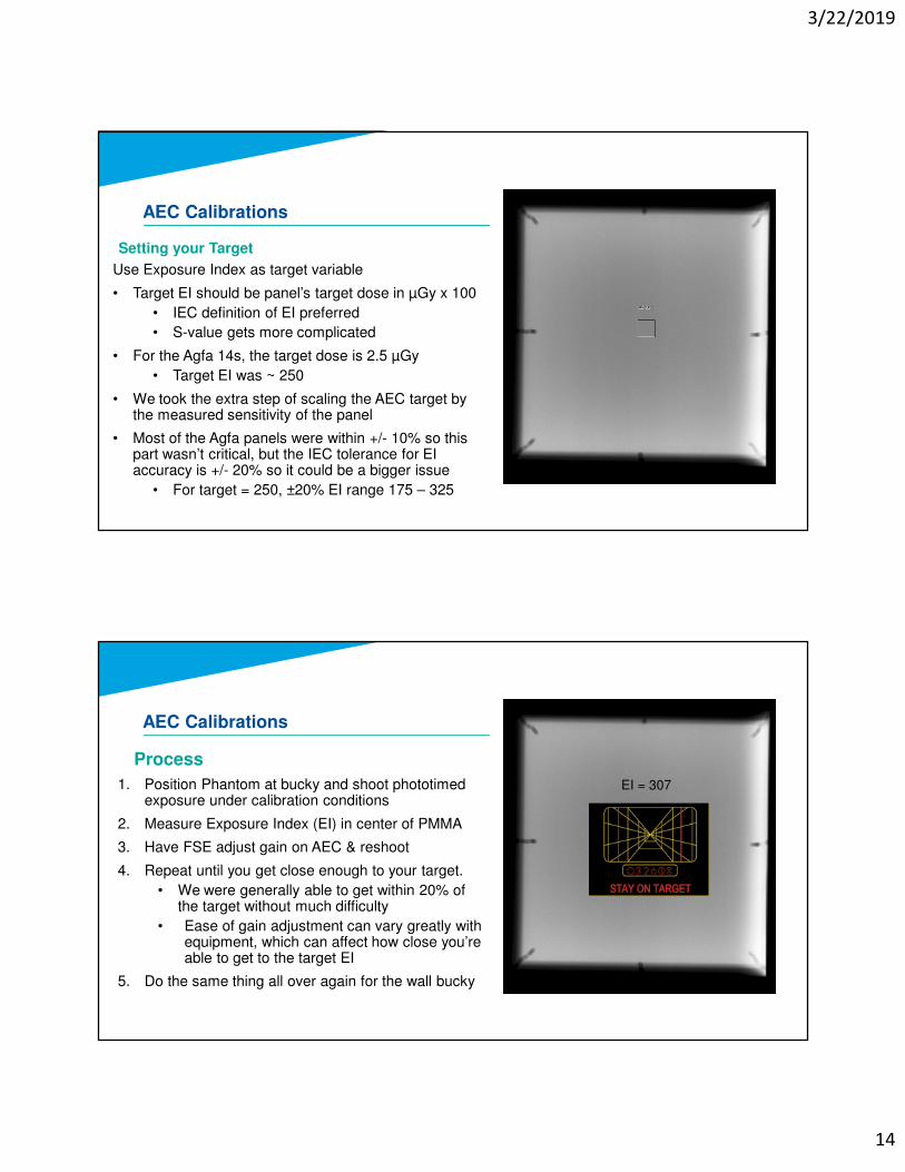
Use Exposure Index as target variable
• Target EI should be panel’s target dose in µGy x 100
• IEC definition of EI preferred
• S-value gets more complicated
• For the Agfa 14s, the target dose is 2.5 µGy
• Target EI was ~ 250
• We took the extra step of scaling the AEC target by the measured sensitivity of the panel
• Most of the Agfa panels were within +/- 10% so this part wasn’t critical, but the IEC tolerance for EI accuracy is +/- 20% so it could be a bigger issue
• For target = 250, ±20% EI range 175 – 325
AEC Calibrations
Setting your Target
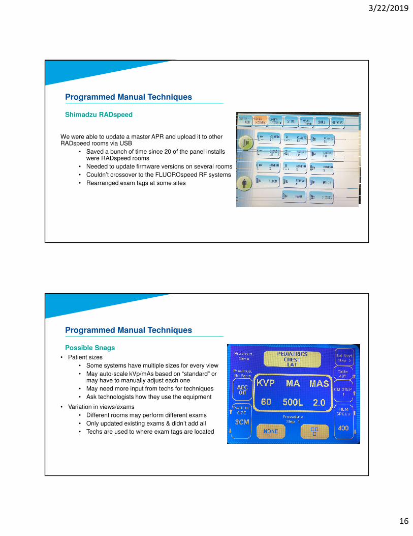
1. Position Phantom at bucky and shoot phototimedexposure under calibration conditions
2. Measure Exposure Index (EI) in center of PMMA
3. Have FSE adjust gain on AEC & reshoot
4. Repeat until you get close enough to your target.
• We were generally able to get within 20% of the target without much difficulty
• Ease of gain adjustment can vary greatly with equipment, which can affect how close you’re able to get to the target EI
5. Do the same thing all over again for the wall bucky
AEC Calibrations
Process
EI = 307

3/22/2019
15
APR Reprograming
Parties Involved
Medical Physics
Field Service Engineers
Site Managers & Technologists
Overview
1. Settle on a standard technique chart
• Work with technologists and radiologists
• Exams may vary at different sites based on practice
• Account for patient size variations
2. Scale existing CR techniques to new DR target dose
• We just scaled mAs down w/ no kVp adjustments
3. Program new techniques into the control panel
• Some systems much more straight forward than others
• May or may not need service engineers
• Manual or upload-able
4. Print and post technique chart as needed
Programmed Manual TechniquesExam Group View SID (in) Grid kVp mAs
Ankle AP 40 N 60 2.5
OBL 40 N 60 2.5
LAT 40 N 60 2.5
Elbow AP 40 N 60 2.0
OBL 40 N 60 2.0
LAT 40 N 60 2.0
Finger AP 40 N 55 1.2
Foot AP 40 N 56 2.0
LAT 40 N 58 2.0
Forearm AP 40 N 58 2.0
Hand AP / OBL 40 N 60 1.5
LAT 40 N 63 1.5
Heel LAT 40 N 60 2.5
Axial 40 N 66 4.9
Hip Hip 40 N 68 6.8
cross-table 40 N 85 37.1
Humerus Humerus 40 N 65 3.1
Knee AP 40 N 65 2.0
LAT 40 N 65 2.0
Tunnel 40 N 70 2.5
Merchant 40 N 70 2.5
Shoulder Axilary 40 N 70 4.9
Tib/Fib Leg 40 N 65 2.5
Manual Technique
TABLETOP
3/22/2019
16
Shimadzu RADspeed
We were able to update a master APR and upload it to other RADspeed rooms via USB
• Saved a bunch of time since 20 of the panel installs were RADspeed rooms
• Needed to update firmware versions on several rooms
• Couldn’t crossover to the FLUOROspeed RF systems
• Rearranged exam tags at some sites
Programmed Manual Techniques
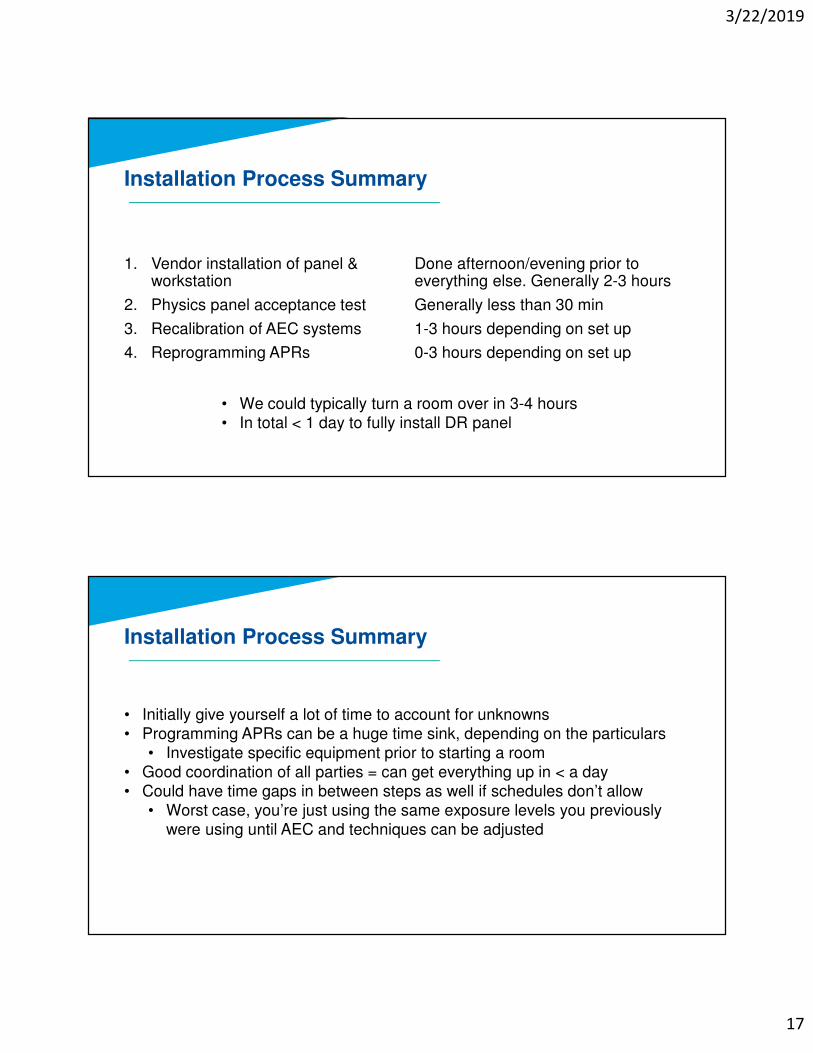
Possible Snags
• Patient sizes
• Some systems have multiple sizes for every view
• May auto-scale kVp/mAs based on “standard” or may have to manually adjust each one
• May need more input from techs for techniques
• Ask technologists how they use the equipment
• Variation in views/exams
• Different rooms may perform different exams
• Only updated existing exams & didn’t add all
• Techs are used to where exam tags are located
Programmed Manual Techniques
3/22/2019
17
Installation Process Summary
1. Vendor installation of panel & workstation
2. Physics panel acceptance test
3. Recalibration of AEC systems
4. Reprogramming APRs
Done afternoon/evening prior to everything else. Generally 2-3 hours
Generally less than 30 min
1-3 hours depending on set up
0-3 hours depending on set up
• We could typically turn a room over in 3-4 hours• In total < 1 day to fully install DR panel
Installation Process Summary
• Initially give yourself a lot of time to account for unknowns • Programming APRs can be a huge time sink, depending on the particulars
• Investigate specific equipment prior to starting a room• Good coordination of all parties = can get everything up in < a day• Could have time gaps in between steps as well if schedules don’t allow
• Worst case, you’re just using the same exposure levels you previously were using until AEC and techniques can be adjusted
3/22/2019
18
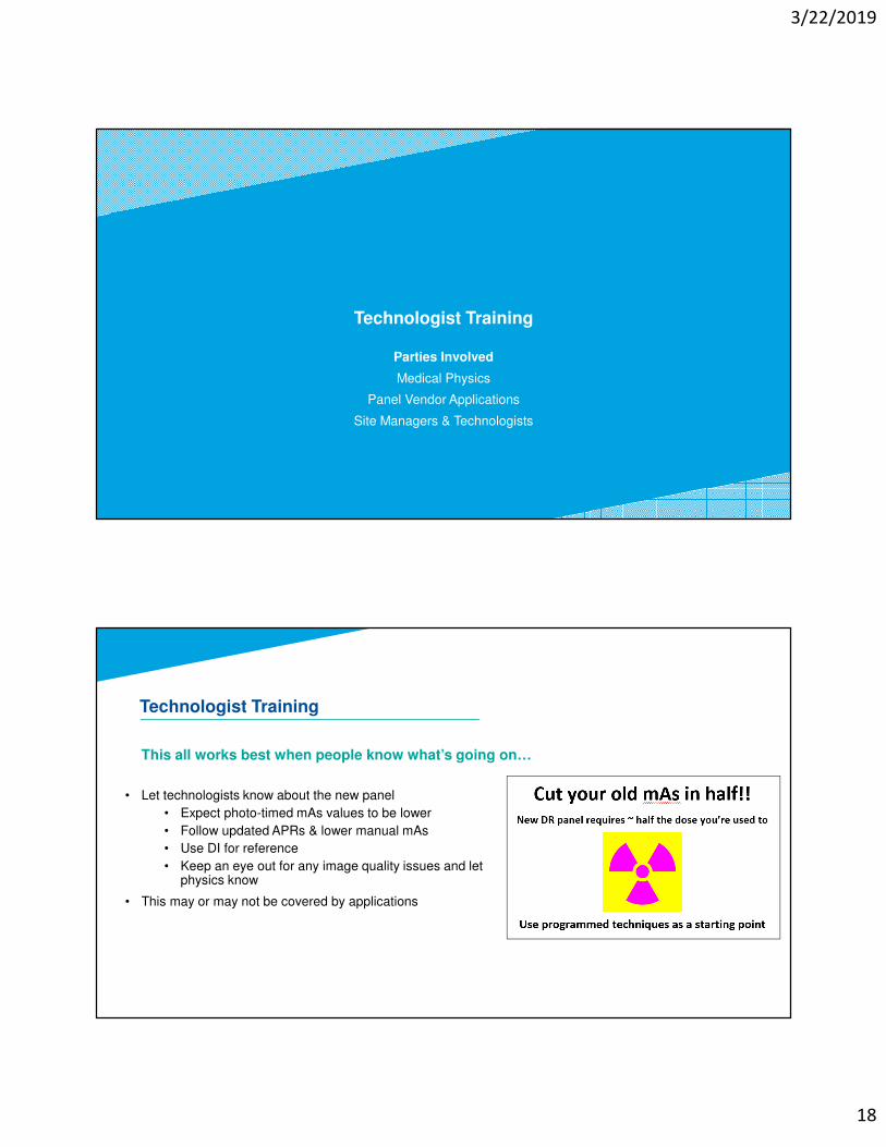
Technologist Training
Parties Involved
Medical Physics
Panel Vendor Applications
Site Managers & Technologists
This all works best when people know what’s going on…
• Let technologists know about the new panel
• Expect photo-timed mAs values to be lower
• Follow updated APRs & lower manual mAs
• Use DI for reference
• Keep an eye out for any image quality issues and let physics know
• This may or may not be covered by applications
Technologist Training
3/22/2019
19
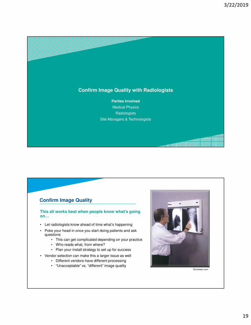
Confirm Image Quality with Radiologists
Parties Involved
Medical Physics
Radiologists
Site Managers & Technologists
• Let radiologists know ahead of time what’s happening
• Poke your head in once you start doing patients and ask questions
• This can get complicated depending on your practice
• Who reads what, from where?
• Plan your install strategy to set up for success
• Vendor selection can make this a larger issue as well
• Different vendors have different processing
• “Unacceptable” vs. “different” image quality
Confirm Image Quality
filmviewer.com
This all works best when people know what’s going on…
3/22/2019
20
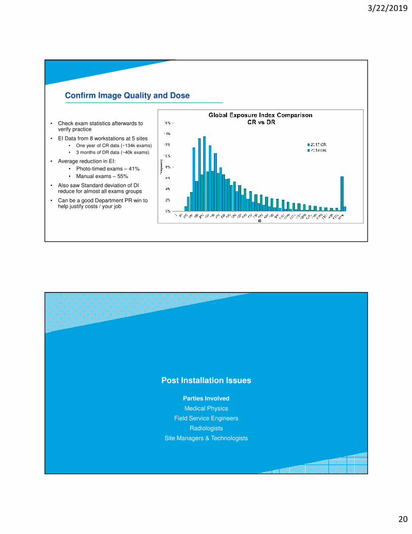
• Check exam statistics afterwards to verify practice
• EI Data from 8 workstations at 5 sites
• One year of CR data (~134k exams)
• 3 months of DR data (~40k exams)
• Average reduction in EI:
• Photo-timed exams – 41%
• Manual exams – 55%
• Also saw Standard deviation of DI reduce for almost all exams groups
• Can be a good Department PR win to help justify costs / your job
Confirm Image Quality and Dose
Post Installation Issues
Parties Involved
Medical Physics
Field Service Engineers
Radiologists
Site Managers & Technologists
3/22/2019
21
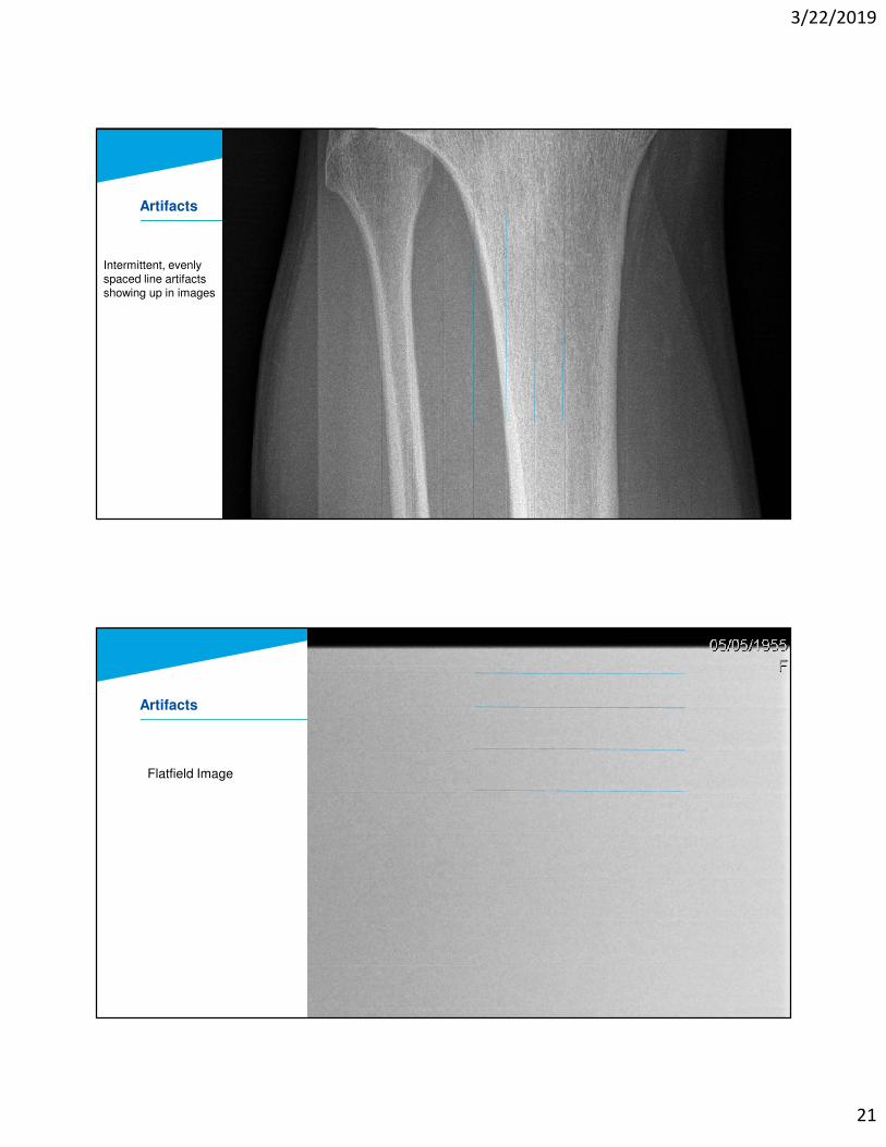
Artifacts
Intermittent, evenly spaced line artifacts showing up in images
Artifacts
Flatfield Image
3/22/2019
22
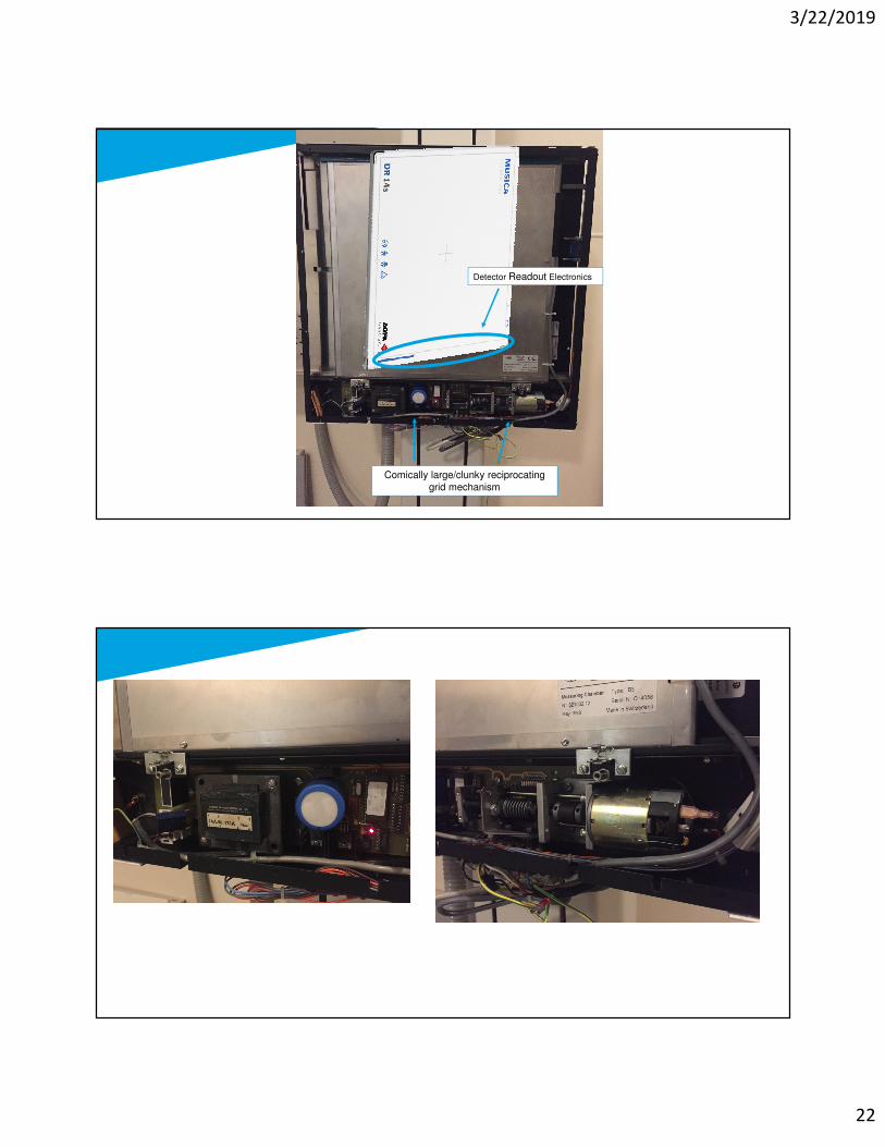
Detector Readout Electronics
Comically large/clunky reciprocating
grid mechanism
3/22/2019
23
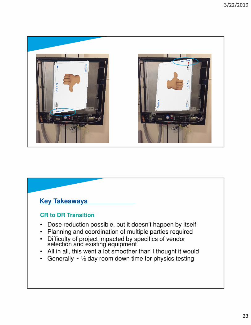
CR to DR Transition
• Dose reduction possible, but it doesn’t happen by itself• Planning and coordination of multiple parties required• Difficulty of project impacted by specifics of vendor
selection and existing equipment• All in all, this went a lot smoother than I thought it would• Generally ~ ½ day room down time for physics testing
Key Takeaways
3/22/2019
24
Thanks!