ac70-manual-v1-3.pdf - Veichi
147
-
Upload
khangminh22 -
Category
Documents
-
view
0 -
download
0
Transcript of ac70-manual-v1-3.pdf - Veichi

Contents Chapter1 Overview .............................................................................................................................................. 1
1.1 Safety Requirement and Cautions ............................................................................................................ 1
1.2 Technical Criterion ..................................................................................................................................... 4
Chapter 2 Before Use .......................................................................................................................................... 7
2.1 Purchase Inspection .................................................................................................................................. 7
2.2 Nameplate ................................................................................................................................................. 7
2.3 Rated Output Current ................................................................................................................................ 8
Chapter 3 Installation and Wiring ...................................................................................................................... 9
3.1 Safety Precautions .................................................................................................................................... 9
3.2 Treatment for Inverter after Longtime Store .............................................................................................. 9
3.3 Inverter Stable Running Environment ..................................................................................................... 10
3.4 EMI Protection ......................................................................................................................................... 11
3.5 Machinery Installation .............................................................................................................................. 13
3.6 Electric Installation ................................................................................................................................... 22
Chapter 4 Basic Operation and Trial Run ....................................................................................................... 37
4.1 Safety Precautions .................................................................................................................................. 37
4.2 Keyboard Layout and Function Specification .......................................................................................... 38
4.3 Basic Operation ....................................................................................................................................... 40
4.4 Trial Run .................................................................................................................................................. 45
Chapter 5 Fault Diagnoses and Processing ................................................................................................... 50
5.1 Fault Types .............................................................................................................................................. 50
5.2 Fault Information and Details .................................................................................................................. 50
5.3 Fault Diagnoses Process ........................................................................................................................ 54
Chapter 6 Periodic Overhaul and Maintenance ............................................................................................. 60
6.1 Safety Precautions .................................................................................................................................. 60
6.2 Overhaul .................................................................................................................................................. 60
6.3 Maintenance ............................................................................................................................................ 61
Chapter 7 Peripheral Equipments and Options ............................................................................................. 64
7.1 Safety Precautions .................................................................................................................................. 64
7.2 Peripheral Equipments ............................................................................................................................ 64
7.3 The Use of Peripheral Equipments ......................................................................................................... 66
Chapter 8 Function Parameter Specification ................................................................................................. 69
8.1 Basic Parameters Specification .............................................................................................................. 69
8.2 External Terminal Parameters................................................................................................................. 93
8.3 .Special Function Parameters ............................................................................................................... 108
Chapter 9 Appendix ......................................................................................................................................... 119
9.1 Appendix 1: Function Code Simple List ................................................................................................ 119
9.2 Appendix 2: RS485 Communication Protocol ....................................................................................... 135
9.3 Appendix 3: LCD Keyboard Manual ...................................................................................................... 141
AC70 VC CONTROL FREQUENCY INVERTER MANUAL OVERVIEW
1
Chapter 1 Overview Thanks for using AC70 series sensorless vector control frequency inverter produced by Veichi Electric co.,ltd. This
manual introduces you how to use it perfectly. Please read this manual carefully and fully understand the safety
requirement and cautions before use (installation, wiring, operation, maintain, checking, and etc...).
1.1 Safety Requirement and Cautions Pls do totally understand this part before using the inverter.
Warning signs and meanings This manual has used below signs that mean there is an important part of security. While observing against the rules,
there is danger of injury even death or machine system damage.
Danger: Wrong operation may cause death or large accident.
Warning: Wrong operation may cause death or large accident.
Caution: Wrong operation may cause minor wound.
Important: Wrong operation may cause the inverter and other machine system damage
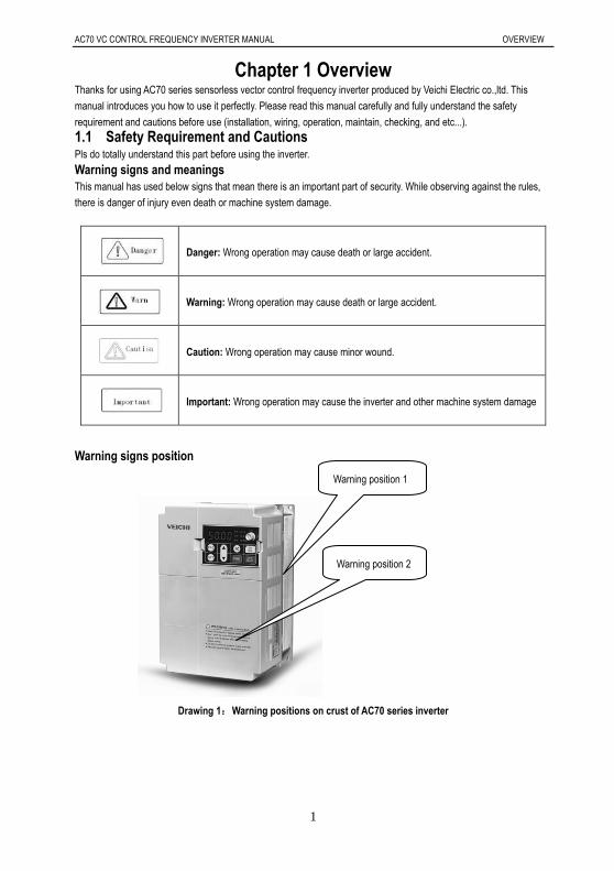
Warning signs position
Drawing 1:Warning positions on crust of AC70 series inverter
Warning position 2
Warning position 1

AC70 VC CONTROL FREQUENCY INVERTER MANUAL OVERVIEW
2
Operation requirement Only Professional trained person are allowed to operate the equipment such as installation, wiring, running, maintain
and etc. “Professional trained person”in this manual means the workers on this product must experience professional
skill train, must be familiar with installation, wiring, running and maintain and can rightly deal with emergency cases in
use.
Safety guidance Safety regulations and warning signs come for your security. They are measures to prevent the operator and machine
system from damage. Please carefully read this manual before using and strictly observe the warning signs while
operating. Safety regulations and warning signs are classified into: routine regulation, transport and store regulation,
installation and wiring regulation, running regulation, maintenance regulation, dismantlement and disposal regulation.
Routine regulation
This product carries dangerous voltage and controls driver machine with potential danger. If
you don’t abide by the regulations or requirements in this manual, there is danger of body
injury even death and machine system damage.
Only qualified personnel are allowed to operate the equipment.this product. Before using, the
operator must be familiar with all safety specifications and operation regulations in this
manual. Safe and stable work of the product is based on right operation and maintenance.
Do not wire while the power is connected. Otherwise, there is danger of death for electric
shock. Before wiring, inspection, maintenance, please cut power supply of all related
equipments and ensure mains DC voltage in safe range. And please operate it after 5 mins.
Away from children and public.
Only used in application fields as maker stated. No use in equipments related to special fields
such as emergency, succor, ship, medical treatment, aviation, nuclear and etc.
Unauthorized alteration or use of accessories which are not sold or recommended by the
maker may cause faults.
Please make sure this manual is in the final user’ hand before using.
Before installation and debugging please carefully read and totally understand these safety
regulation and warning signs.
Transport and store regulation
Correct transport, store, installation and careful operation an maintenance are important for
inverter safe operation.
In transport and store process, make sure the inverter is free from impact and vibration. It
must be stored where is dry without corrosive air and conductive dust, and the temperature
must be lower than 60.
Installation and wiring regulation
Only professional trained person can operate it.
Power wire, motor wire and control wire should be all connected firmly. Earth must be reliable
and earth resistance must be lower than 10Ω.
Before opening the inverter, please disconnect all related equipment power supply and make
sure the mains DC voltage is in safe range and operate after 5mins.
Human body electrostatic will damage inner sensitive components seriously. Before
operation, please follow ESD measures. Otherwise, there is danger of inverter damage.
Inverter output voltage is pulse wave. If components such as capacitor which improves power
factor and pressure-sensitive resistance for anti-thunder and so on are installed at the output
side, please dismantle them or change to input side.

AC70 VC CONTROL FREQUENCY INVERTER MANUAL OVERVIEW
3
No switch components such as breaker and contactor at the output side. (If there must be
one, please make sure the output current is 0 while the switch acting).
The power supply cable and motor cable specifications must satisfy all conditions in table 3-7
3-8 .
Run regulation
Inverter runs at high voltage. So dangerous voltage is in some components inevitably.
No matter where the fault is, there is danger of serious accident, even human body injury
what means dangerous malfunction possibility. So there must be additional external prevent
measures or other safety devices, such as independent current limiting switch, machinery
and so on.
Maintenance regulation
Only Shenzhen Veichi Electric co., ltd service department or its authorized service center or
professional person trained and authorized by Veichi can maintain the products. They should
be very familiar with the safety warning and operation gist in this manual.
Any defective components must be changed in time.
Before opening the inverter to repair please cut power supply of all related equipments and
ensure mains DC voltage in safe range. And please do operation after 5 mins.
Dismantlement and disposal regulation
Packing case can be reused. Please keep them and reuse or send back to maker.
Dismantled metal components are retractable and can be reused.
Some components such as electrolytic capacitor are harmful to environment. Please dispose
according to environmental protection departments.

AC70 VC CONTROL FREQUENCY INVERTER MANUAL OVERVIEW
4
1.2 Technical Specification
Tech.
Specification Items Description
Power Input
Voltage, frequency single phase 220V, 3 phase, 220V,380V, 660V and 1140V
Allowable fluctuations Voltage:<±15%; frequency±5%
Distortion of voltage to confirm to IEC61800-2
Closing striking current less than rated current
Power Factor ≥0.94( integrated DC reactor)
Efficiency ≥96%
Power
Output
Output Voltage 3 Phase, 0~Input voltage, tolerance less than 5% in standard
rating condition
Frequency Control Range
G type: 0 to 400Hz, P type: 0-400Hz, Z type: 0-400Hz, L type:
0-400Hz,
H type: 0-3000Hz.
Output frequency accuracy ±5% of maximum frequency
Overload Tolerance
Z type: 150% rated current for 60 sec, 180% rated current for 30
sec, 250% rated current for instantaneous
G, H, L type model: 150% of rated output current for 60 sec,180% of
rated current for 10s, 2 00% of rated current for instantaneous
P type: 120% rated current 60 sec, 150% rated current for
instantaneous
Key Control
performance
Motor Control Mode Open loop sensorless vector control without PG, V/F control
Control system Optimized Space Vector PWM Modulation
Carrier frequency 0.6~15kHz, Randomly-modulated carrier
Speed control range OLV without PG with rated load: 1:100,
Stable speed control accuracy OLV without PG: less than 1% rated synchronous speed
Torque response OLV without PG control mode: ≤20ms
Frequency Accuracy
(Temperature Fluctuation)
Digital inputs: maximum × ±0.01%
Analog inputs: maximum × ± 0.2%
Frequency Setting Resolution Digital inputs: 0.01 Hz
Analog inputs: 0.5% of maximum output frequency
Standard
Function
DC Braking
Starting Frequency: 0.00 to 50.00Hz,
Braking Time: 0.0 to 60.0s
Braking current: 0.0 to 150% rated current
Torque boost Auto torque boost:0.0% to 100%
Manual torque boost: 0.0% to 25%

AC70 VC CONTROL FREQUENCY INVERTER MANUAL OVERVIEW
5
V/F curve
5 kinds curve programmable setting:1 user setting, 1 of linear
characteristic torque curve setting. 3 kinds derating torque
setting( 1.5 power, 1.7 power, 2.0 Power curve )
Accel / Decel. curve Two kinds curve: line Accel/Decel, S curve Accel/Decel.
4 Aceel/Decel time unit is 0.1s, maximum time 6500.0s
Rated output voltage Power voltage compensation is available, setting range from 50 to
100%( rated voltage), the output voltage can't over than input
AVR( Auto Voltage Regulation automatic voltage regulation for keeping output voltage stable when
fluctuation of grid
Auto energy saving running Optimized the output voltage according the load to achieve energy
saving
Auto current limit Auto current limit during running mode to avoid trip occurs
frequently
Momentary Power Loss with
no stop running function
To achieve continuous running with regenerative enery and DC bus
voltage regulation when momentary power loss
Standard Function
PID control, Carrier frequency adjustable, current limiter, Speed
Search, Momentary Power Loss restart,8 Step Speed (max), 3-wire
Sequence, Slip Compensation, Frequency Jump, Upper/lower
Limits for Frequency Reference, DC Injection Braking at Start and
Stop, Energy Saving Control, Modbus Comm RS485, Fault Restart,
job function, Cooling Fan on/off Switch, timing stop, high pulse
output, programmable auto running, swing frequency, counter,
frequency arriving detect and frequency lever detect.
Frequency Setting Methods
Keypad digital setting, potentiometer of keypad, analog voltage
terminal VS1, analog voltage terminal VS2, analog current terminal
AS, RS485 communication and multiple terminal, main and auxiliary
composition setting.
Feedback Input Channel voltage terminal VS1, VS2, current terminal AS, communication ,
and pulse input PUL
Running command channel keypad given, external terminal given, communication given
Input command signal Start, Stop, FEW/Reverse, Job, Multiple speed, free stop, Reset,
Accel/Decel time, Frequency set point channel, External fault
Output signal
2 Photo coupler relays: 2 (24 V, up to 50 mA)
1 Contact relays: 1 (250 Vac/up to 1 A, 30 Vdc/up to 1 A)
0-10V output, 4 to 20mA output
Frequency pulse output
Protection function Overvoltage, under voltage, current limit, over current, overload,
electric thermal relay, overheat, Stall prevention, parameter lock

AC70 VC CONTROL FREQUENCY INVERTER MANUAL OVERVIEW
6
keypad
Display
LED Display One line digit-segments LED display to monitor 1 running status
Double line digit-segment display to monitor 1 running status
Parameters copy upload and download parameter code to achieve easy copy
Monitor Function
Output frequency, Frequency set point, Out current, Output voltage,
motor speed, PID feedback value, PID given setting, IGBT module
temperature, I/O terminal status.
Alarms
Overvoltage, under voltage, over current, short circuit, phase loss,
over load, over heat, stall prevention, current limit, parameter lock
damage, running status at present alarm, past trip alarm
Environment
Installation Site Indoor, Altitude should less than 1000m, Free corrosive gases and
direct sunlight
Running Temperature,
humidity
-10~+40°C ( wall mounting),
20% to 95% RH (No condensation)
Vibration Less than 0.5g when frequency less than 20Hz
Storage Temperature -25—+65°C
Installation mode Wall-mounted mode, floor stand cabinet install
Protection Degree IP20
Cooling Method Forced air-cooling
Table 1: Technical Specification

AC70 VC CONTROL FREQUENCY INVERTER MANUAL BEFORE USE
7
Chapter 2 Before Use 2.1 Purchase Inspection Pls check whether any package is damaged while receiving the product you ordered. If the package is ok, pls open it
and check the inverter. If damage caused in transport, it is not duty of Veichi company. But please contact Veichi or the
transport company immediately.
After checking the product, please also check if the model is the one you ordered.The model of the product is on the
nameplate “MODEL”column. If the model is not in accordance with your need, please contact the agent or the sales
departments in our company.
2.2 Nameplate Nameplate position and content
MODEL: AC70-T3-011G/015P
SOURCE: 3 380V 50/60Hz
OUTPUT1: 11KW 25A 0.00-400.0Hz
SER NO:
OUTPUT2: 15KW 32A 0.00-400.0Hz
G models output
Model
P models output
Input power
Production series no******************
Chart 2-1: AC70 series inverter nameplate
Model explanation
AC70 - T 3 - 011 G /015 P
2 220V3 380V6 660V
GPZ
7R5011015
7.51115
018022030
18.52230
L
11 1140V
H
AC70
GDPD
Cabinet with baseCabinet with base
code voltage class
T three phase
S single phase
code voltage class
code inverter typegeneral format
blower and water pump
plastic machine
draw benchmid inverter governor
code fit power of motor(kW)
General use
inverter series
Chart 2-2: AC70series inverter nameplate meaning and naming rules

AC70 VC CONTROL FREQUENCY INVERTER MANUAL BEFORE USE
8
2.3 Rated Output Current
Input voltage 220V 380V 660V 1140V
Rated power (kw) Rated output current (A)
0.4 2.5
0.75 4 2.3
1.5 7 3.7
2.2 10 5.0
4 16 10
5.5 20 13
7.5 30 17 10
11 42 25 15
15 55 32 18
18.5 70 38 22
22 80 45 28
30 110 60 35
37 130 75 45 25
45 160 90 52 31
55 200 110 63 38
75 260 150 86 52
90 320 180 98 58
110 380 210 121 75
132 420 250 150 86
160 550 310 175 105
185 600 340 198 115
200 660 380 218 132
220 720 415 235 144
250 470 270 162
280 510 330 175
315 600 345 208
355 670 380 220
400 750 430 260
450 810 466 270
500 860 540 325
560 990 600 365
630 1100 680 400
AC70 VC CONTROL FREQUENCY INVERTER MANUAL INSTALLATION AND WIRING
9
Chapter 3: Installation and Wiring
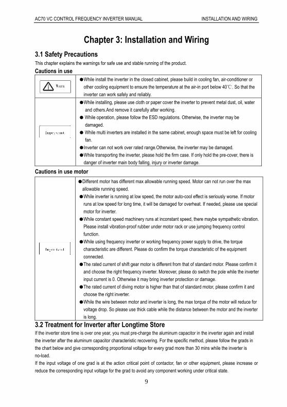
3.1 Safety Precautions This chapter explains the warnings for safe use and stable running of the product.
Cautions in use
While install the inverter in the closed cabinet, please build in cooling fan, air-conditioner or
other cooling equipment to ensure the temperature at the air-in port below 40. So that the
inverter can work safely and reliably.
While installing, please use cloth or paper cover the inverter to prevent metal dust, oil, water
and others.And remove it carefully after working.
While operation, please follow the ESD regulations. Otherwise, the inverter may be
damaged.
While multi inverters are installed in the same cabinet, enough space must be left for cooling
fan.
Inverter can not work over rated range.Otherwise, the inverter may be damaged.
While transporting the inverter, please hold the firm case. If only hold the pre-cover, there is
danger of inverter main body falling, injury or inverter damage.
Cautions in use motor
Different motor has different max allowable running speed. Motor can not run over the max
allowable running speed.
While inverter is running at low speed, the motor auto-cool effect is seriously worse. If motor
runs at low speed for long time, it will be damaged for overheat. If needed, please use special
motor for inverter.
While constant speed machinery runs at inconstant speed, there maybe sympathetic vibration.
Please install vibration-proof rubber under motor rack or use jumping frequency control
function.
While using frequency inverter or working frequency power supply to drive, the torque
characteristic are different. Please do confirm the torque characteristic of the equipment
connected.
The rated current of shift gear motor is different from that of standard motor. Please confirm it
and choose the right frequency inverter. Moreover, please do switch the pole while the inverter
input current is 0. Otherwise it may bring inverter protection or damage.
The rated current of diving motor is higher than that of standard motor, please confirm it and
choose the right inverter.
While the wire between motor and inverter is long, the max torque of the motor will reduce for
voltage drop. So please use thick cable while the distance between the motor and the inverter
is long.
3.2 Treatment for Inverter after Longtime Store If the inverter store time is over one year, you must pre-charge the aluminum capacitor in the inverter again and install
the inverter after the aluminum capacitor characteristic recovering. For the specific method, please follow the grads in
the chart below and give corresponding proportional voltage for every grad more than 30 mins while the inverter is
no-load.
If the input voltage of one grad is at the action critical point of contactor, fan or other equipment, please increase or
reduce the corresponding input voltage for the grad to avoid any component working under critical state.

AC70 VC CONTROL FREQUENCY INVERTER MANUAL INSTALLATION AND WIRING
10
Chart 3-1: treatment for inverter after longtime store
3.3 Inverter Stable Running Environment Installation environment is very important to the best use of this product for long time. Pls install this product in the
environment as the following table requirement.
Environment Requirement
Install place Indoor without direct sunshine
Install temperature -10 ~ +40
Store temperature -20 ~ +60
Humidity <95%RH, no condensation
Surrounding
Please install the inverter in place as follows:
Place without oil mist, corrosive gases, flammable gas, dust or etc.
Place without metal dust, oil, water or etc into inverter (please do not install inverter on
flammable material such as food and etc).
Place without radioactive material or flammable material.
Place without poisonous gases or liquid.
Place with very little salification erosion.
Place whihout direct sunshine.
Altitude <1000m
Vibration <10~20Hz:9.8m/s2
<20~55Hz:5.9m/s2
Installation and
cooling
Inverter can not be installed horizontally must be installed vertically.
Please independently install high heating equipments such as braking resistor and etc which
can not be installed in the same cabinet with inverter, installed at the air-in port of the inverter
is strictly prohibited.
Table 3-1:AC70 series inverter running environment condition
In order to improve the product stability, pls do not use the inverter where temperature changes sharply. While
using in closed space such as control cabinet, please use cooling fan or air-condition to cool inverter to avoid
temperature over limit range. Please also prevent inverter from freeze, too low temperature may cause components
freeze fault.
AC70 VC CONTROL FREQUENCY INVERTER MANUAL INSTALLATION AND WIRING
11
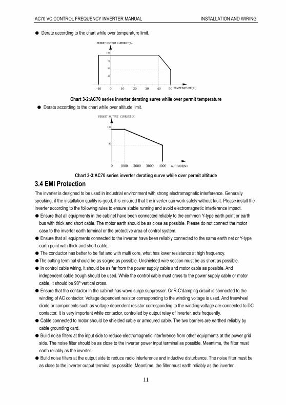
Derate according to the chart while over temperature limit.
30
25
100
75
50
4020100-10 50 TEMPERATURE()
PERMIT OUTPUT CURRENT(%)
Chart 3-2:AC70 series inverter derating surve while over permit temperature
Derate according to the chart while over altitude limit.
0 1000 2000 4000
80
100
3000 ALTITUDE(M)
PERMIT OUTPUT CURRENT(%)
Chart 3-3:AC70 series inverter derating surve while over permit altitude
3.4 EMI Protection The inverter is designed to be used in industrial environment with strong electromagnetic interference. Generally
speaking, if the installation quality is good, it is ensured that the inverter can work safely without fault. Please install the
inverter according to the following rules to ensure stable running and avoid electromagnetic interference impact.
Ensure that all equipments in the cabinet have been connected reliably to the common Y-type earth point or earth
bus with thick and short cable. The motor earth should be as close as possible. Please do not connect the motor
case to the inverter earth terminal or the protective area of control system.
Ensure that all equipments connected to the inverter have been reliably connected to the same earth net or Y-type
earth point with thick and short cable.
The conductor has better to be flat and with multi core, what has lower resistance at high frequency.
The cutting terminal should be as soigne as possible. Unshielded wire section must be as short as possible.
In control cable wiring, it should be as far from the power supply cable and motor cable as possible. And
independent cable trough should be used. While the control cable must cross to the power supply cable or motor
cable, it should be 90º vertical cross.
Ensure that the contactor in the cabinet has wave surge suppresser. Or‘R-C’damping circuit is connected to the
winding of AC contactor. Voltage dependent resistor corresponding to the winding voltage is used. And freewheel
diode or components such as voltage dependent resistor corresponding to the winding voltage are connected to DC
contactor. It is very important while contactor, controlled by output relay of inverter, acts frequently.
Cable connected to motor should be shielded cable or armoured cable. The two barriers are earthed reliably by
cable grounding card.
Build noise filters at the input side to reduce electromagnetic interference from other equipments at the power grid
side. The noise filter should be as close to the inverter power input terminal as possible. Meantime, the filter must
earth reliably as the inverter.
Build noise filters at the output side to reduce radio interference and inductive disturbance. The noise filter must be
as close to the inverter output terminal as possible. Meantime, the filter must earth reliably as the inverter.

AC70 VC CONTROL FREQUENCY INVERTER MANUAL INSTALLATION AND WIRING
12
Anytime, control circuit wire should be shielded cable.
Add zero phase reactor in power supply wire near inverter input terminal and add zero phase reactor in the motor
wire near inverter output terminal to reduce electromagnetic interference to the inverter efficiently.
Earthing Right and reliable earthing is the basic condition of safe and reliable running of the product. For right
earthing, please read the following notice carefully.
In order to avoid electric shock, earthing cable should be the size as electric
equipment technique standard required and cable length should be as short as
possible. Otherwise, inverter leakage current will cause unstable potential of the
earthing terminal which is far from the earthing point, and electric shock accident will
happen frequently.
Earth terminal must be earthing. Earth resistance must be below 10Ω. Otherwise,
there is danger of death.
Please do not share earth cable with welder or other big current/pulse power
equipment. Otherwise, inverter will act abnormally.
While multi inverters are used at the same time, please do not wind the earth wire to
loop-type. Otherwise, inverter will act abnormally.
Chart 3-4: multi AC70 series inverters united earthing
Chart 3-5:AC70 series inverter system earthing
Remark: motor must earth as close as possible. Motor case can not be connected to the inner earth terminal of the
inverter. It also can not share the earth net with the control system.
Shield of inverter power cable, motor cable, control cable Cable
Shielding layer (reticulate/armoured) should be winded reliably by cable earth card and fix to inverter earth piece by bolt.
Please refer to the following chart.

AC70 VC CONTROL FREQUENCY INVERTER MANUAL INSTALLATION AND WIRING
13
Chart 3-6:Cable earth card for cables earthing
Corresponding relationship between inverter/motor cable length and carrier frequency.
While cable distance between inverter and motor is long (especially low frequency output), cable voltage drop will make
motor torque reduce. Further more, cable HF leakage current will increase. Then inverter output current will increase,
that will cause inverter over-current trip. The current detection accuracy and running stability will be impacted. Please
follow as below table to adjust carrier frequency according to the cable length. While the cable distance is over 100m,
please adopt distributed capacity reduce measure (Such as “no metal conductor covers cable”, “wire each phase cable
apart” and so on).
Cable length <20m 20~50m 50~100m >100m
Carrier frequency 0.7~15kHz 0.7~8kHz 0.7~4kHz 0.7~2kHz
Table 3-2: Corresponding relationship between inverter/motor cable length and carrier frequency
3.5 Machinery Installation
Installation notice and related requirement
AC70 inverter components
Chart 3-7:AC70 series inverter components

AC70 VC CONTROL FREQUENCY INVERTER MANUAL INSTALLATION AND WIRING
14
Installation direction
To prevent inverter cooling effect reducing, please do install the inverter vertically.
Chart 3-8:AC70 series inverter installation direction
Installation space
Single machine installation: to ensure enough ventilation and wiring space for inverter cooling, please follow installation
conditions as follows. The back of the inverter should stick to the wall. So that the surrounding air of radiator can flow
freely to ensure the cooling effect.
Chart 3-9:Single AC70 series inverter installation space
Multi inverters paratactic installation: while installing multi inverters in cabinet, please ensure installation space as
follows.
Chart 3-10: Multi AC70 series inverters paratactic installation space requirement

AC70 VC CONTROL FREQUENCY INVERTER MANUAL INSTALLATION AND WIRING
15
Dimension of Inverter and Keyboard
WW1
DD1
HH1
Inverter model Inverter size Install size Install
aperture W H D D1 W1 H1
AC70-S2-R40G
122 182 154.5 145 112 171 ф5 AC70-S2-R75G
AC70-S2-1R5G
AC70-S2-2R2G 159 246 157.5 148 147.2 236 ф5.5
AC70-S2-004G
AC70-S2-5R5G 195 291 167.5 158 179 275 ф7
AC70-T3-R75G/1R5P
122 182 154.5 145 112 171 ф5 AC70-T3-1R5G/2R2P
AC70-T3-2R2G/004P
AC70-T3-004G/5R5P 159 246 157.5 148 147.2 236 ф5.5
AC70-T3-5R5G/7R5P
AC70-T3-7R5G/011P 195 291 167.5 158 179 275 ф7
AC70-T3-011G/015P
AC70-T3-015G/018P(plastic cover machine)
230 330 200 190 208 315 Ф7 AC70-T3-018G/022P
(plastic cover machine) AC70-T3-022G/030P
(plastic cover machine)

AC70 VC CONTROL FREQUENCY INVERTER MANUAL INSTALLATION AND WIRING
16
WW1 D
H H1
H2
Install aperture
Inverter model Inverter size Install size Install
aperture W H D H2 W1 H1
AC70-T3-015G/018P (steel cover machine)
235 345 200 311 160 331.5 ф7 AC70-T3-018G/022P
(steel cover machine)
AC70-T3-022G/030P (steel cover machine) 255 410 225 370 180 395 Ф7
AC70-T3-030G/037P
AC70-T3-037G/045P
305 570 260 522 180 550 Ф9 AC70-T3-045G/055P
AC70-T3-055G/075P
AC70-T3-075G/093P
380 620 290 564 240 595 ф11 AC70-T3-093G/110P
AC70-T3-110G/132P
AC70 VC CONTROL FREQUENCY INVERTER MANUAL INSTALLATION AND WIRING
17
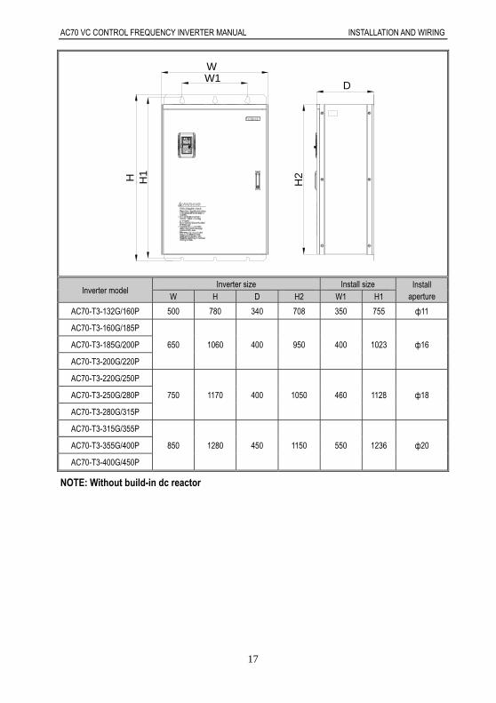
H1H H2
DW1W
Inverter model Inverter size Install size Install
aperture W H D H2 W1 H1
AC70-T3-132G/160P 500 780 340 708 350 755 ф11
AC70-T3-160G/185P
650 1060 400 950 400 1023 ф16 AC70-T3-185G/200P
AC70-T3-200G/220P
AC70-T3-220G/250P
750 1170 400 1050 460 1128 ф18 AC70-T3-250G/280P
AC70-T3-280G/315P
AC70-T3-315G/355P
850 1280 450 1150 550 1236 ф20 AC70-T3-355G/400P
AC70-T3-400G/450P NOTE: Without build-in dc reactor

AC70 VC CONTROL FREQUENCY INVERTER MANUAL INSTALLATION AND WIRING
18
D1
W1
DW
H H1
Inverter model Inverter size Install size Install
aperture W H D H1 W1 D1
AC70-T3-160GD/185PD
650 1600 400 1500 492 332 ф14 AC70-T3-185GD/200PD
AC70-T3-200GD/220PD
AC70-T3-220GD/250PD
750 1700 400 1600 582 332 ф14 AC70-T3-250GD/280PD
AC70-T3-280GD/315PD
AC70-T3-315GD/355PD
850 1800 450 1700 622 382 ф14 AC70-T3-355GD/400PD
AC70-T3-400GD/450PD NOTE: With build-in dc reactor

AC70 VC CONTROL FREQUENCY INVERTER MANUAL INSTALLATION AND WIRING
19
H H1
D1
W1
DW
Inverter model Inverter size Install size Install
aperture W H D H1 W1 D1
AC70-T3-450G/500P
1200 1850 550 1750 960 466 ф14 AC70-T3-500G/560P
AC70-T3-560G/630P
Table 3-3:AC70 series inverter dimension

AC70 VC CONTROL FREQUENCY INVERTER MANUAL INSTALLATION AND WIRING
20
Keyboard dimension
Chart 3-11:AC70 series inverter 1 line LED keyboard dimension
Chart 3-12:AC70 series inverter mouth for 1 line LED keyboard dimension
114.5
65.5 19.5
16.5
17.1
110.5
63.5
35.6
53.75
Chart 3-13:AC70 series inverter 2 line LED keyboard dimension

AC70 VC CONTROL FREQUENCY INVERTER MANUAL INSTALLATION AND WIRING
21
119
70
111
64
142
75
Mouth for keyboard with boxAC70-T3-160G/630P
Mouth for keyboard with box
AC70-T3-015G/132P
Mouth for keyboard with box
Chart 3-14:AC70 series inverter mouth for 2 line LED keyboard dimension
Note: LCD keyboard total same size as LED keyboard.
Dismantle and install tail-hood
Installation: First the tail-hood upwardly inclines around 15
degrees and inserts the top fixed flat into the fixed hole in the
front cover. Then slightly press the tail-hood downward. While
your hear "Ka", it means that the tail-hood is into the place.
Chart 3-15:AC70 series inverter tail-hood installation
Dismantlement: At the tail of the frequency inverter, there is a
special dismantlement hole design. Put your finger into the
hole, upwardly pull the cover with a little force until the buckle
between the tail-hood and the crust tear off, and then remove
the tail-hood down.
Chart 3-16:AC70 series inverter tail-hood dismantlement

AC70 VC CONTROL FREQUENCY INVERTER MANUAL INSTALLATION AND WIRING
22
Dismantlement and installation of keyboard
Chart 3-17:AC70 series inverter keyboard installation and dismantlement
3.6 Electric Installation This chapter explains the regulations that users have to obey to ensure safe use, best performance and reliable
running.
Safety precaution
Must earth reliably while inverter is running. Otherwise there is danger of casualty and unstable inverter performance.
To ensure safe running, only trained professional person can do installation and wiring job.
No operation under power connected state. Otherwise there is danger of electric shock even death.
Before operation, please cut all related equipments power, ensure that the main circuit DC current has dropped to safe range. And please operate after 5 mins.
Control cable, power cable and motor cable must be separated. They can not be in the same cable trough or cable rack.
This equipment can only be used as the maker states. Please consult Veichi while using in special case.
No insulation test for the inverter or the related cable by HV insulation test equipment.
If the inverter or the peripheral equipment (filer, reactor and etc) needs insulation test,
firstly 500V megohmmeter should be used to test the insulation resistance which should
not be lower than 4MΩ.
AC70 VC CONTROL FREQUENCY INVERTER MANUAL INSTALLATION AND WIRING
23
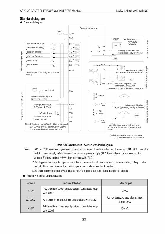
Standard diagram Standard diagram
Note1
Note:multiple function digtal input defaultsetting
TA
TB
TC
+24V
Y1
_mA 20
10
0
-+
0
5
10V_
+ -
GNDA01
VRVR mini 2Kohm
Analog current Input +10V
Fre
quen
cy r
efer
ence
set
ting
inpu
t
VS2
GND
AS
VS1
twisted-pair shielding line(grounding nearby)
pulse input PUL
Mul
ti-fu
nctio
n d
igita
l inp
ut
COM
X3
X4
X6
X5
X1
X2
PLC
+24V
Frequency Inverter
GNDA02
coil
Y2
COM
pass
ive
sour
ce o
utpu
tAC220V
AC0V
J1J2J3
switch
Maximum output:
3A/240VAC5A/30VDC
2. VS1/VS2 terminal resistor valuve 89ohm1 Maximum output 50mA +10V input terminalNote:
2 Maximum output of Y1/Y2 DC24V/50mA
Note:
Mark:1. stand for main loop terminal
(Forward Run/Stop)
(0~5V)/(0~10V)
(0~20mA)/(4~20mA)
3 AS terminal resistor valuve 250ohm
J4
J5
(Reverse Run/Stop)
(Jog run forward)
(Jog run Reverse)
(Free stop)
(Fault reset)
Note3
Analog voltage Input
twisted-pair shielding line(grounding nearby by inverter)
twisted-pair shieldingline (grounding nearby by inverter)
Note: 1 Maximum output of +24V terminal-DC 24v/100mA
Pinswitch
coil
coil
twisted-pair shielding line (grounding nearby by inverter)
Note2
Note: Maximum output is 2mA whenA01/A02 as for frequency voltage signaloutput
2. stand for control loop terminal
colle
ctor
type
sta
tus
outp
utan
alog
mon
itor
sign
al o
utpu
tChart 3-18:AC70 series inverter standard diagram
Note: 1.NPN or PNP transistor signal can be selected as input of multi-function input terminal(X1~X6). Inverter
built-in power supply (+24V terminal) or external power supply (PLC terminal) can be chosen as bias
voltage. Factory setting ‘+24V’ short connect with ‘PLC’.
2. Analog monitor output is special output of meters such as frequency meter, current meter, voltage meter
and etc. It can not be used for control operations such as feedback control.
3. As there are multi pulse styles, please refer to the line connect mode description details.
Auxiliary terminal output capacity
Terminal Function definition Max output
+10V 10V auxiliary power supply output, constitutes loop
with GND. 50mA
A01/A02 Analog monitor output, constitutes loop with GND. As frequency,voltage signal, max
output 2mA
+24V 24V auxiliary power supply output, constitutes loop
with COM. 100mA
AC70 VC CONTROL FREQUENCY INVERTER MANUAL INSTALLATION AND WIRING
24
Y1/Y2 Collector open circuit output, can set the
action-object by program. DC24V/50mA
TA/TB/TC Passive connector output,can set the action-object
by program.
3A/240VAC
5A/30VDC
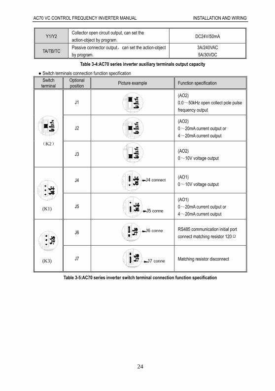
Table 3-4:AC70 series inverter auxiliary terminals output capacity
Switch terminals connection function specification Switch
terminal Optional position
Picture example Function specification
(K2)
J1 (AO2)
0.0~50kHz open collect pole pulse
frequency output
J2 (AO2)
0~20mA current output or
4~20mA current output
J3 (AO2)
0~10V voltage output
(K1)
J4 J4 connect(AO1)
0~10V voltage output
J5 J5 conne
(AO1)
0~20mA current output or
4~20mA current output
(K3)
J6 J6 conne RS485 communication initial port
connect matching resistor 120Ω
J7 J7 conne Matching resistor disconnect
Table 3-5:AC70 series inverter switch terminal connection function specification

AC70 VC CONTROL FREQUENCY INVERTER MANUAL INSTALLATION AND WIRING
25
Main circuit wiring Main circuit wiring
Chart 3-19:AC70 frequency inverter main circuit wiring Note: 1, Fuse, dc reactor, braking unit, braking resistor, input actor, input filter,output reactor, output filter are optional parts, please refer to “peripheral equipment”. 2, P1 terminal and (+) short connect. If need add dc reactor, please take away the short connect part between P1 and (+). Main circuit terminals Main circuit terminals array and definition Arrangement sequence of main circuit terminal with 18.5kW or less power(15 ~ 18.5KW for steel cover machine)
(-) TSRPB U WV(+) E
Arrangement sequence of main circuit terminal with 15-22KW(15~22KW for plastic cover machine)

AC70 VC CONTROL FREQUENCY INVERTER MANUAL INSTALLATION AND WIRING
26
Arrangement sequence of main circuit terminal with 22~30KW (standard machine without PB terminal)(22KW for steel
cover machine)
Arrangement sequence of main circuit terminal with 37~110kW
Arrangement sequence of main circuit terminal with 132kW: Arrangement sequence of main circuit terminal with 160~560kW
Terminal Name
(-) DC power terminal
DC power output, (-) means DC bus cathode, (+) means DC bus anode, used for external braking unit. (+)
(+) Braking resistance terminal Used for external braking resistance to realize quick stop.
PB
P1 DC reactor terminal Used for external DC reactor.
(+)
R
Inverter input terminal Used to connect 3-phase AC power supply. S
T
U
Inverter output terminal Used to connect the motor. V
W
Earth Earth terminal, earth resistance<10 OHM
E
Table 3-6:AC70 series inverter main circuit terminals array and definition

AC70 VC CONTROL FREQUENCY INVERTER MANUAL INSTALLATION AND WIRING
27
3-phase 380V machine main circuit wiring
Model Main circuit terminals screw specifications
Suggested fixed moment (N·m)
Suggested Copper-core cable specification mm2 (AWG)
AC70-T3-R75G/1R5P M4 1.2~1.5 1.5mm2(14)
AC70-T3-1R5G/2R2P M4 1.2~1.5 2.5mm2(12)
AC70-T3-2R2G/004P M4 1.2~1.5 2.5mm2(12)
AC70-T3-004G/5R5P M4 1.2~1.5 4mm2(10)
AC70-T3-5R5G/7R5P M4 1.2~1.5 6mm2(9)
AC70-T3-7R5G/011P M5 2~2.5 6mm2(9)
AC70-T3-011G/015P M5 2~2.5 10mm2(7)
AC70-T3-015G/018P M6 4~6 10mm2(7)
AC70-T3-018G/022P M6 4~6 16mm2(5)
AC70-T3-022G/030P M8 8~10 16mm2(5)
AC70-T3-030G/037P M8 8~10 25mm2(3)
AC70-T3-037G/045P M8 8~10 25mm2(3)
AC70-T3-045G/055P M8 8~10 35mm2(2)
AC70-T3-055G/075P M10 11~13 35mm2(2)
AC70-T3-075G/093P M10 11~13 50mm2(1)
AC70-T3-093G/110P M10 11~13 50mm2(1/0)
AC70-T3-110G/132P M10 11~13 70mm2(2/0)
AC70-T3-132G/160P M10 11~13 95mm2(3/0)
AC70-T3-160G/185P M12 14~16 95mm2(4/0)
AC70-T3-185G/200P M12 14~16 120mm2
AC70-T3-200G/220P M12 14~16 150mm2
AC70-T3-220G/250P M12 14~16 150mm2
AC70-T3-250G/280P M12 14~16 185mm2
AC70-T3-280G/315P M12 14~16 185mm2
AC70-T3-315G/355P M16 20~23 240mm2
AC70-T3-355G/400P M16 20~23 240mm2
AC70-T3-400G/450P M16 20~23 300mm2
AC70-T3-450G/500P M16 20~23 400mm2
AC70-T3-500G/560P M16 20~23 400mm2
AC70-T3-560G/630P M16 20~23 500mm2
Note: Here we suggest to use copper joins as mains electric connectors of machine over 185KW. Pls refer the cut section area above.
Table 3-7: Suggested cable diameter and fixed moment 3-phase 380V machine main circuit

AC70 VC CONTROL FREQUENCY INVERTER MANUAL INSTALLATION AND WIRING
28
Single-phase 220V machine main circuit wiring
Model Main circuit terminals screw specifications
Suggested fixed moment (N·m)
Suggested Copper-core cable specification mm2 (AWG)
AC70-S2-R40G M4 1.2~1.5 1.5mm2(14)
AC70-S2-R75G M4 1.2~1.5 2.5mm2(12)
AC70-S2-1R5G M4 1.2~1.5 2.5mm2(12)
AC70-S2-2R2G M4 1.2~1.5 4mm2(10)
Table 3-8: Suggested cable diameter and fixed moment single-phase 220V machine main circuit Suggested main circuit components specification
Model Contactor
specification Breaker
specification DC reactor Input filter Output filter
AC70-T3-R75G/1R5P 10A 10A ------ NFI-005 NFO-010
AC70-T3-1R5G/2R2P 10A 10A ------ NFI-005 NFO-010
AC70-T3-2R2G/004P 16A 15A ------ NFI-010 NFO-010
AC70-T3-004G/5R5P 16A 20A ------ NFI-010 NFO-010
AC70-T3-5R5G/7R5P 25A 20A ------ NFI-020 NFO-020
AC70-T3-7R5G/011P 25A 30A ------ NFI-020 NFO-020
AC70-T3-011G/015P 32A 40A ------ NFI-036 NFO-036
AC70-T3-015G/018P 40A 50A ------ NFI-036 NFO-036
AC70-T3-018G/022P 50A 60A ------ NFI-050 NFO-050
AC70-T3-022G/030P 50A 75A DCL-50 NFI-050 NFO-050
AC70-T3-030G/037P 63A 100A DCL-80 NFI-080 NFO-080
AC70-T3-037G/045P 80A 125A DCL-100 NFI-100 NFO-100
AC70-T3-045G/055P 100A 150A DCL-110 NFI-100 NFO-100
AC70-T3-055G/075P 125A 175A DCL-125 NFI-150 NFO-150
AC70-T3-075G/093P 160A 200A DCL-150 NFI-150 NFO-150
AC70-T3-093G/110P 220A 250A DCL-200 NFI-200 NFO-300
AC70-T3-110G/132P 220A 300A DCL-200 NFI-200 NFO-300
AC70-T3-132G/160P 250A 400A DCL-300 NFI-300 NFO-300
AC70-T3-160G/185P 300A 500A DCL-300 NFI-300 NFO-300
AC70-T3-185G/200P 400A 600A DCL-400 NFI-400 NFO-400
AC70-T3-200G/220P 400A 700A DCL-400 NFI-400 NFO-400
AC70-T3-220G/250P 630A 800A DCL-500 NFI-600 NFO-600
AC70-T3-250G/280P 630A 1000A DCL-600 NFI-600 NFO-600
AC70-T3-280G/315P 630A 1200A DCL-600 NFI-600 NFO-600
AC70-T3-315G/355P 630A 1200A DCL-800 ------ ------
AC70-T3-355G/400P 800A 1400A DCL-800 ------ ------
AC70-T3-400G/450P 1000A 1600A DCL-1000 ------ ------
AC70-T3-450G/500P 1000A 2000A DCL-1000 ------ ------
AC70 VC CONTROL FREQUENCY INVERTER MANUAL INSTALLATION AND WIRING
29
AC70-T3-500G/560P 1000A 2000A DCL-1200 ------ ------
AC70-T3-560G/630P ------ 2000A DCL-1200 ------ ------
Note: For DC reactor, input filter, output filter and other components specification details and circuit mode, please refer
chapter 7 “peripheral equipments and options” Table 3-9: Suggested mains fittings for 3-phase 380V machine
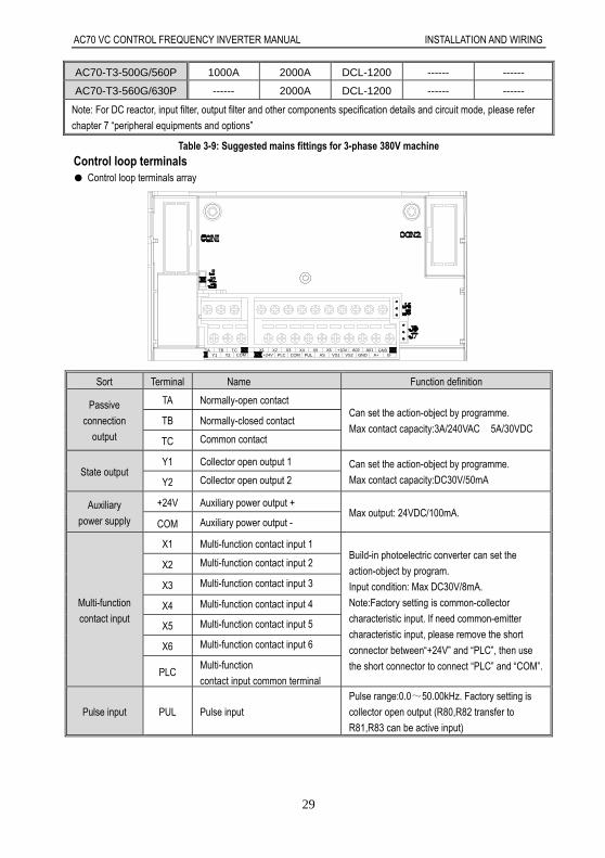
Control loop terminals Control loop terminals array
+10V GNDX6TB TCTA A02X1 X2 X5VS1COMY2Y1 +24V PLCCOM PUL A+AS GND
X3 X4 A01VS2 B-
Sort Terminal Name Function definition
Passive
connection
output
TA Normally-open contact Can set the action-object by programme.
Max contact capacity:3A/240VAC 5A/30VDC TB Normally-closed contact
TC Common contact
State output Y1 Collector open output 1 Can set the action-object by programme.
Max contact capacity:DC30V/50mA Y2 Collector open output 2
Auxiliary
power supply
+24V Auxiliary power output + Max output: 24VDC/100mA.
COM Auxiliary power output -
Multi-function
contact input
X1 Multi-function contact input 1 Build-in photoelectric converter can set the
action-object by program.
Input condition: Max DC30V/8mA.
Note:Factory setting is common-collector
characteristic input. If need common-emitter
characteristic input, please remove the short
connector between“+24V” and “PLC”, then use
the short connector to connect “PLC” and “COM”.
X2 Multi-function contact input 2
X3 Multi-function contact input 3
X4 Multi-function contact input 4
X5 Multi-function contact input 5
X6 Multi-function contact input 6
PLC Multi-function
contact input common terminal
Pulse input PUL Pulse input
Pulse range:0.0~50.00kHz. Factory setting is
collector open output (R80,R82 transfer to
R81,R83 can be active input)
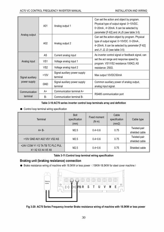
AC70 VC CONTROL FREQUENCY INVERTER MANUAL INSTALLATION AND WIRING
30
Analog output
A01 Analog output 1
Can set the action and object by program.
Physical type of output signal: 0~10VDC.
0~20mA , 4~20mA. It can be selected by
parameter [F-62] and J4,J5 (see table 3-5)
A02 Analog output 2
Can set the action-object by program. Physical
type of output signal: 0~10VDC. 0~20mA ,
4~20mA, It can be selected by parameter [F-62]
and J1 J2 J3 (see table 3-5)
Analog input
AS Current analog input As inverter control signal or feedback signal, can
set the act range and response speed by
program. VS1/VS2 resistance:100KΩ; AS
resistance: 250Ω.
VS1 Voltage analog input 1
VS2 Voltage analog input 2
Signal auxiliary
power supply
+10V Signal auxiliary power supply
terminal Max output 10VDC/50mA
GND Signal auxiliary power supply
terminal
Common auxiliary power of analog output,
analog input signal.
Communication
terminal
A+ Communication terminal A+ RS485 communication port
B- Communication terminal B-
Table 3-10:AC70 series inverter control loop terminals array and definition
Control loop terminal wiring specification
Terminal
Bolt
specification
(mm)
Fixed moment
(N·m)
Cable
specification
(mm2)
Cable type
A+ B- M2.5 0.4~0.6 0.75 Twisted-pair
shielded cable
+10V GND A01 A02 VS1 VS2 AS M2.5 0.4~0.6 0.75 Twisted-pair
shielded cable
+24V COM Y1 Y2 TA TB TC PLC PUL
X1 X2 X3 X4 X5 X6 M2.5 0.4~0.6 0.75 Shielded cable
Table 3-11:Control loop terminal wiring specification
Braking unit (braking resistance) connection Brake resistance wiring of machine with 18.5KW or less power(15KW-18.5KW for steel cover machine)
(-) (+) PB R S T U V W E
Brakeingresistor
Fig 3-20: AC70 Series Frequency Inverter Brake resistance wiring of machine with 18.5KW or less power

AC70 VC CONTROL FREQUENCY INVERTER MANUAL INSTALLATION AND WIRING
31
Brake resistance wiring of machine with 15-22KW(for plastic cover machine)
Brakeingresistor
Fig 3-21: AC70 Series Frequency Inverter Brake resistance wiring of machine with 15-22KW(for plastic cover machine)
Brake resistance wiring of machine with 22KW and 30KW(built-in brake is optional)(22KW for steel cover machine)
TSR PB U WV
POWER INPUT MOTOR OUTPUT
Brakeingresistor
(-)(+)
Fig 3-22: AC70 Series Frequency Inverter Brake resistance wiring of machine with 22KW and 30KW(built-in
brake is optional)(22KW for steel cover machine)
Brake resistance wiring of machine with 37KW or above
TSR PB U WV
POWER INPUT MOTOR OUTPUT
Dynamic Brake Unit
POWER ACTIVE
- + + PB
Brakeingresistor
(-)(+)
Fig 3-23: AC70 Series Frequency Inverter Brake resistance wiring of machine with 37KW or above
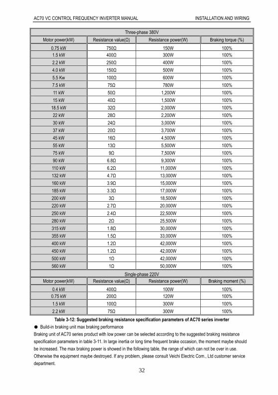
Suggested braking resistance specification parameters
Braking resistance value and power in the chart are decided according to common inertia load and intermittent braking
mode. While used in large inertia occasion or long time frequent brake occasion, please adjust resistance value and
power according to the inverter specification and the rated parameter of braking unit. If any problem, please consult
customer service department of Veichi Electric Com., Ltd.
AC70 VC CONTROL FREQUENCY INVERTER MANUAL INSTALLATION AND WIRING
32
Three-phase 380V
Motor power(kW) Resistance value(Ω) Resistance power(W) Braking torque (%)
0.75 kW 750Ω 150W 100% 1.5 kW 400Ω 300W 100%
2.2 kW 250Ω 400W 100%
4.0 kW 150Ω 500W 100%
5.5 Kw 100Ω 600W 100%
7.5 kW 75Ω 780W 100%
11 kW 50Ω 1,200W 100%
15 kW 40Ω 1,500W 100%
18.5 kW 32Ω 2,000W 100%
22 kW 28Ω 2,200W 100%
30 kW 24Ω 3,000W 100%
37 kW 20Ω 3,700W 100%
45 kW 16Ω 4,500W 100%
55 kW 13Ω 5,500W 100%
75 kW 9Ω 7,500W 100%
90 kW 6.8Ω 9,300W 100%
110 kW 6.2Ω 11,000W 100%
132 kW 4.7Ω 13,000W 100%
160 kW 3.9Ω 15,000W 100%
185 kW 3.3Ω 17,000W 100%
200 kW 3Ω 18,500W 100%
220 kW 2.7Ω 20,000W 100%
250 kW 2.4Ω 22,500W 100%
280 kW 2Ω 25,500W 100%
315 kW 1.8Ω 30,000W 100%
355 kW 1.5Ω 33,000W 100%
400 kW 1.2Ω 42,000W 100%
450 kW 1.2Ω 42,000W 100%
500 kW 1Ω 42,000W 100%
560 kW 1Ω 50,000W 100%
Single-phase 220V Motor power(kW) Resistance value(Ω) Resistance power(W) Braking moment (%)
0.4 kW 400Ω 100W 100% 0.75 kW 200Ω 120W 100%
1.5 kW 100Ω 300W 100%
2.2 kW 75Ω 300W 100%
Table 3-12: Suggested braking resistance specification parameters of AC70 series inverter
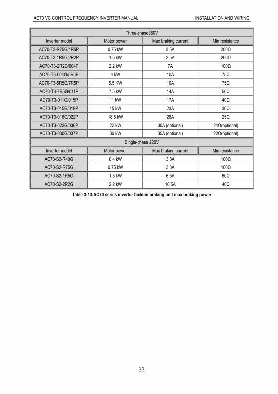
Build-in braking unit max braking performance
Braking unit of AC70 series product with low power can be selected according to the suggested braking resistance
specification parameters in table 3-11. In large inertia or long time frequent brake occasion, the moment maybe should
be increased. The max braking power is showed in the following table, the range of which can not be over in use.
Otherwise the equipment maybe destroyed. If any problem, please consult Veichi Electric Com., Ltd customer service
department.
AC70 VC CONTROL FREQUENCY INVERTER MANUAL INSTALLATION AND WIRING
33
Three-phase380V
Inverter model Motor power Max braking current Min resistance
AC70-T3-R75G/1R5P 0.75 kW 3.5A 200Ω
AC70-T3-1R5G/2R2P 1.5 kW 3.5A 200Ω
AC70-T3-2R2G/004P 2.2 kW 7A 100Ω
AC70-T3-004G/5R5P 4 kW 10A 75Ω
AC70-T3-5R5G/7R5P 5.5 KW 10A 75Ω
AC70-T3-7R5G/011P 7.5 kW 14A 50Ω
AC70-T3-011G/015P 11 kW 17A 40Ω
AC70-T3-015G/018P 15 kW 23A 30Ω
AC70-T3-018G/022P 18.5 kW 28A 25Ω
AC70-T3-022G/030P 22 kW 30A (optional) 24Ω(optional)
AC70-T3-030G/037P 30 kW 35A (optional) 22Ω(optional)
Single-phase 220V
Inverter model Motor power Max braking current Min resistance
AC70-S2-R40G 0.4 kW 3.8A 100Ω
AC70-S2-R75G 0.75 kW 3.8A 100Ω
AC70-S2-1R5G 1.5 kW 6.5A 60Ω
AC70-S2-2R2G 2.2 kW 10.5A 40Ω
Table 3-13:AC70 series inverter build-in braking unit max braking power

AC70 VC CONTROL FREQUENCY INVERTER MANUAL INSTALLATION AND WIRING
34
Multi-function contact input connection NPN transistor connection mode
use inner 24v power AC70+24V
PLC
X1
X2
X4
X3
X6
X5
COM
shielded cale E
factory short connect
E
COM
X5
X6
X3
X4
X2
X1
PLC
+24V
dismantle 24v and PLC connector
+-
exterior 24v power AC70
exterior control signal
exterior control signal
shielded cale
use exterior 24v power
Chart 3-24: NPN transistor digital input signal connection mode
PNP transistor connection mode
-+
E
X5
X6
X3
X4
X2
X1
PLC
+24V AC70use exterior 24v power
COMCOM
use inner 24v power AC70
+24V
PLC
X1
X2
X4
X3
X6
X5
shielded cale
exterior control signal
exterior 24v power
shielded cale
exterior control signal
E
Chart 3-25 PNP transistor digital input signal connection mode
Digital output signal connection
double shielded cable
COM
control exterior relay by inner 24V power of inverter
wind
E
Y1
+24V
COM
exterior 24v power
-+
COM
+24V
Y1
E
COM
double shielded cable
control exterior relay by inner 24V power of inverter
AC70 AC70
wind
Chart 3-26:AC70 series inverter digital output signal connection mode
AC70 VC CONTROL FREQUENCY INVERTER MANUAL INSTALLATION AND WIRING
35
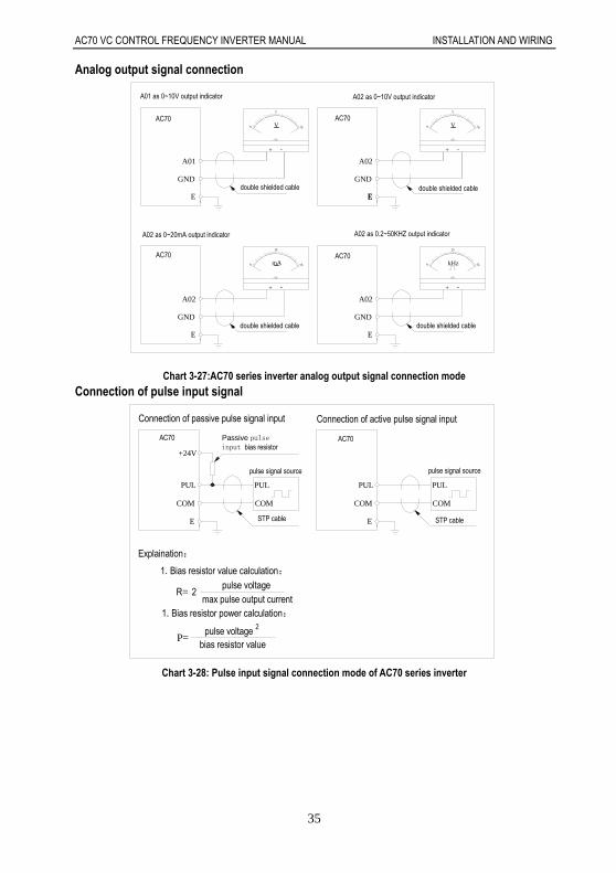
Analog output signal connection
E
A02
GND
GND
E
A02
E
GND
E
A01
double shielded cable
-+
_V 10
5
0
A01 as 0~10V output indicator
0
5
10V_
+ -
A02
E
GND
010
20mA_ kHz 50
25
0
-+ + -
A02 as 0~10V output indicator
double shielded cable
double shielded cable double shielded cable
A02 as 0~20mA output indicator A02 as 0.2~50KHZ output indicator
AC70 AC70
AC70 AC70
Chart 3-27:AC70 series inverter analog output signal connection mode
Connection of pulse input signal
COM
E
PUL
AC70
Connection of passive pulse signal input
+24V
Passive pulseinput bias resistor
STP cable
pulse signal source
COM
PUL PUL
E
COM
1.Bias resistor value calculation:
R=max pulse output current
pulse voltage2
Explaination:
2
P=pulse voltage
bias resistor value
PUL
COM
AC70
Connection of active pulse signal input
pulse signal source
STP cable
1.Bias resistor power calculation:
Chart 3-28: Pulse input signal connection mode of AC70 series inverter

AC70 VC CONTROL FREQUENCY INVERTER MANUAL INSTALLATION AND WIRING
36
Standby control system Frequency inverter is composed of semiconductor, passive electronic component and driving part. All of them have
useful time, which means these parts may happen characteristic change or out of use in normal working environment.
And it will cause product fault. To avoid production stop led by the fault, we suggest preparing standby control system
when using the inverter.
Chart 3-29 is a standby control system for manual switch to power supply driving motor at inverter fault. Standby control
systems such as power supply Y/Δ step-down start way driving motor, power supply self-coupling reduction voltage
start mode driving motor, power supply soft start mode driving motor or standby inverter system can be chose to use
according the actual requirement and environment.
Chart 3-29: Standby control system of power supply directly driving mode

AC70 VC CONTROL FREQUENCY INVERTER MANUAL BASIC OPERATION AND TRIAL RUN
37
Chapter 4: Basic Operation and Trial Run4.1 Safety Precautions
No wiring while power supply is connected.Otherwise there is danger of electric shock.
No operation while the cover is open.Otherwise, there is danger of electric shock.
Please ensure reliable earth. Otherwise,there is danger of electric shock and fire.
Before wiring please cut power supply of all related equipments and ensure main DC
voltage in safe range. And please do operation after 5 mins.
Only professional trained person is allowed to operate this product.
Please do not dismantle the inverter cover while it is electrified. Otherwise, there is danger
of electric shock.
Please do not touch the printed circuit board of the inverter while it is electrified.
Otherwise, there is danger of electric shock.
Please ensure reliable mains cable connection. If the mains cable is loose, there is danger
of fire caused by joint overheat.
Before electrifying, please check the power voltage again. Wrong power voltage can
cause fault or damage the inverter, even cause fire.
Please do not install inverter on flammable material or attach flammable material to the
inverter. Before electrifying, please clear the surroundings.
Important
While operation, please follow the ESD regulations. Otherwise, the inverter maybe
damaged.
Please don’t cut the power directly while the inverter drives the motor running. The power
can’t be cut until the motor totally stop. Otherwise, the inverter maybe damaged.
Please don’t cut or connect motor while the inverter drives the motor running. The motor
can’t be cut or connect until the inverter output is 0. Otherwise, the inverter maybe
damaged.
Control cable should be twisted-pair shielded cable. The barrier should be
connected to the inverter earth terminal reliably to prevent the inverter from abnormal
working.
Unprofessional person can not operate, install, wiring, debug and maintain.
Change, dismantle or maintain without permission may cause inverter damage. This case
is not within our quality assurance range.
AC70 VC CONTROL FREQUENCY INVERTER MANUAL BASIC OPERATION AND TRIAL RUN
38
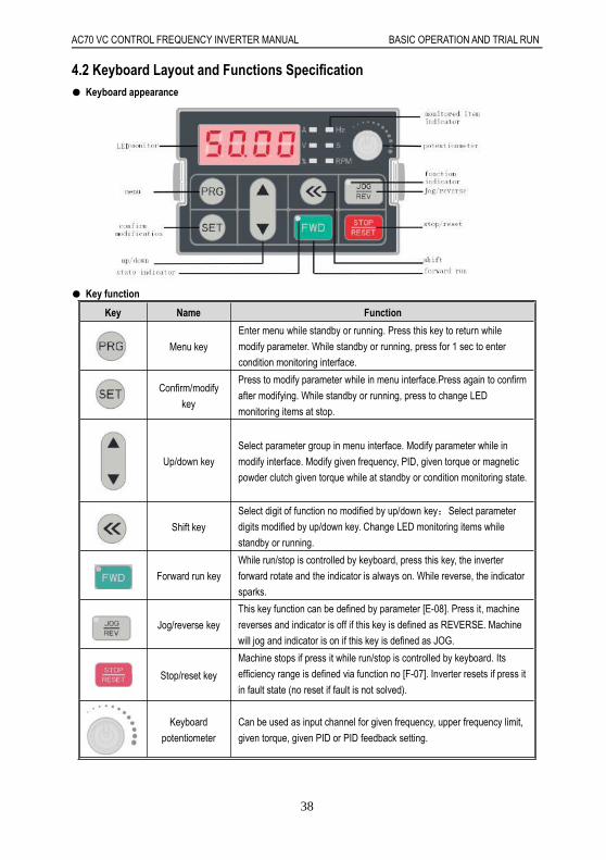
4.2 Keyboard Layout and Functions Specification Keyboard appearance
Key function
Key Name Function
Menu key
Enter menu while standby or running. Press this key to return while
modify parameter. While standby or running, press for 1 sec to enter
condition monitoring interface.
Confirm/modify
key
Press to modify parameter while in menu interface.Press again to confirm
after modifying. While standby or running, press to change LED
monitoring items at stop.
Up/down key
Select parameter group in menu interface. Modify parameter while in
modify interface. Modify given frequency, PID, given torque or magnetic
powder clutch given torque while at standby or condition monitoring state.
Shift key
Select digit of function no modified by up/down key;Select parameter
digits modified by up/down key. Change LED monitoring items while
standby or running.
Forward run key
While run/stop is controlled by keyboard, press this key, the inverter
forward rotate and the indicator is always on. While reverse, the indicator
sparks.
Jog/reverse key
This key function can be defined by parameter [E-08]. Press it, machine
reverses and indicator is off if this key is defined as REVERSE. Machine
will jog and indicator is on if this key is defined as JOG.
Stop/reset key
Machine stops if press it while run/stop is controlled by keyboard. Its
efficiency range is defined via function no [F-07]. Inverter resets if press it
in fault state (no reset if fault is not solved).
Keyboard
potentiometer
Can be used as input channel for given frequency, upper frequency limit,
given torque, given PID or PID feedback setting.

AC70 VC CONTROL FREQUENCY INVERTER MANUAL BASIC OPERATION AND TRIAL RUN
39
Indicator light meanings
Name State Meaning
Unit indicator
light
Hz Spark Digital display given frequency.
Hz On Digital display output frequency.
A On Digital display actual output current.
V On Digital display input voltage.
V Spark Digital display output voltage.
S On Time unit is second.
S Spark Time unit is ms, min, or h.
RPM On Digital display motor speed.
% Spark Digital display given PID.
% On Digital display PID feedback.
State
indicator light
FWD On Inverter is forward rotating.
FWD Spark Inverter is reverse rotating.
FWD Off Inverter stops.
Function
indicator light
REV/JOG On Jog.
REV/JOG Off Reverse.
Chart 4-1: Indicator light meanings
Number and character table
Chart 4-2:Number and character table

AC70 VC CONTROL FREQUENCY INVERTER MANUAL BASIC OPERATION AND TRIAL RUN
40
LED keyboard stamp explain:
Stamp Explain
Frequency inverter stop
FWD
REV
JOG
REV second stamp
Remind press key
Remind press key
Cursor can up or remind up
Cursor can down or remind down
It flashing means fault
Arrowhead direction
Terminal not connect
Terminal connect
Two relay output: one on, another off
4.3 Basic Operation4.3.1 Menu Structure and Operation
AC70 series frequency inverter parameter setting adopts 3 groups of menus which can be checked and modified easily.Three menus are basic parameter, external terminal parameter and special function parameters. Operation method:
PRG
Standy or running Basic parameter External terminal parameter Special function parameters
PRG PRG
PRG
Chart 4-1: FWD/REV and 3 groups of menus switch operationNote: One line display and dual line display keypad has the same operation process and operation method.

AC70 VC CONTROL FREQUENCY INVERTER MANUAL BASIC OPERATION AND TRIAL RUN
41
4.3.2 State Display SwitchingThe LED display kinds of monitor parameters of AC70 series inverter in running or stop mode. User can uses [E-06,E-07] to select specific monitor parameters in one line display keypad, also can uses [E-06, E-07] to select upper linedisplay and lower line display contents in two line display keypad.User can uses SET and shift key to see specific monitor parameter in one-way circulation in one line display keypad or
in two line display keypad. Please refer to following operation flow chart.
1, One line display keyboard cycle switching display.
Chart 4-2: One line display keyboard cycle dislay

AC70 VC CONTROL FREQUENCY INVERTER MANUAL BASIC OPERATION AND TRIAL RUN
42
2. Dual line keypad cycle switching display monitor parameters operation flow chart.
PID feedback value
Giving frequency
%
%RPM
RPM
VA
VA
Hz
Hz
Hz
Hz
A V
A V
RPM
RPM %
%
Motor speed
Input voltage
Motor speed
PID giving value
%
%RPM
RPM
VA
VA
Hz
Hz
Hz
Hz
A V
A V
RPM
RPM %
%
PID feedback value
PID giving valueOutput current
Input voltage
%
%RPM
RPM
VA
VA
Hz
Hz
Hz
Hz
A V
A V
RPM
RPM %
%
Output current
Giving
Output
OffSparkOn
%
%RPM
RPM
VA
VA
Hz
Hz
Change first line parameter by cycle
Change second line parameter by cycle
frequency
frequency
frequencyOutput
SET
SET
SET
SET
SET
SET
SET
SET
Chart 4-3: Dual line display keypad cycle display

AC70 VC CONTROL FREQUENCY INVERTER MANUAL BASIC OPERATION AND TRIAL RUN
43
4.3.3 Parameter Setting Mode
AC70 series frequency inverter best performance is based on parameter right setting. Here take[F-08]as a sample to
show how to set parameter for both small keyboard and big keyboard.
1, Small keyboard set mode
PRG SET
PRG
PRG
SET
PRG
Stanby or running state
Enter menu
Function paramer no
Change digit
Find parameter no
Enter next menu
Change digit
Find paramerter no
Back menu
Enter parameter modify state
Change digit
Display parameter and spark
Change paramer value
Back
Confirm
Chart 4-4: Small keyboard parameter set

AC70 VC CONTROL FREQUENCY INVERTER MANUAL BASIC OPERATION AND TRIAL RUN
44
2, Big keyboard set mode
Function paramer no
Stanby or running state
Parameter value spark
Paramerter no
Parameter no
Back
Change digit
PRG
Find paramerter no
Change digit
Change digit
SET
Enter next menu
Confirm
Enter parameter modify state
Change paramer value
Enter menu
Find parameter no
Parameter no
Parameter value
Parameter value
Parameter value
Pameter value
Parameter no
Paramerter no
Parameter value
PRG
SET
PRG
PRG
Chart 4-5: Big keyboard parameter set
AC70 VC CONTROL FREQUENCY INVERTER MANUAL BASIC OPERATION AND TRIAL RUN
45
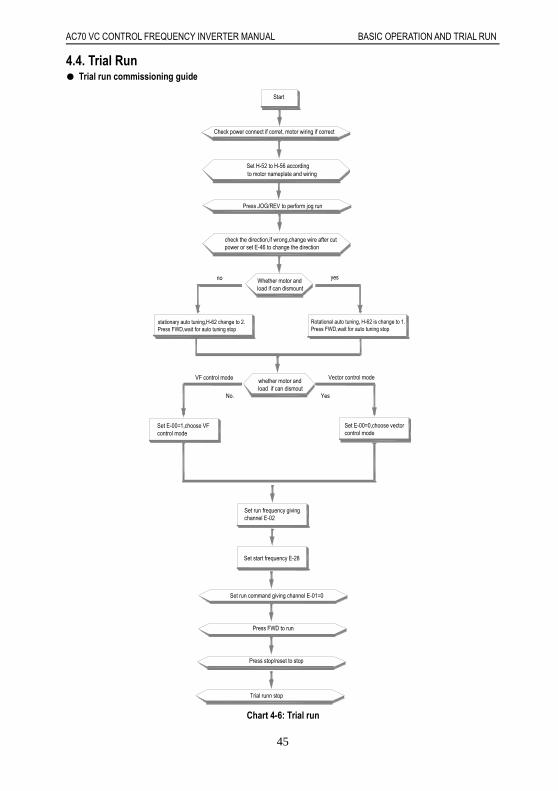
4.4. Trial Run Trial run commissioning guide
Trial runn stop
Press stop/reset to stop
Press FWD to run
Set run command giving channel E-01=0
Set start frequency E-28
Set run frequency givingchannel E-02
whether motor andload if can dismout
Set E-00=0,choose vectorcontrol mode
Set E-00=1,choose VFcontrol mode
Vector control modeVF control mode
Rotational auto tuning, H-62 is change to 1.Press FWD,wait for auto tuning stop
stationary auto tuning,H-62 change to 2.Press FWD,wait for auto tuning stop
Whether motor andload if can dismount
yesno
check the direction,if wrong,change wire after cutpower or set E-46 to change the direction
Start
Press JOG/REV to perform jog run
to motor nameplate and wiringSet H-52 to H-56 according
Check power connect if corret, motor wiring if correct
YesNo.
Chart 4-6: Trial run
AC70 VC CONTROL FREQUENCY INVERTER MANUAL BASIC OPERATION AND TRIAL RUN
46
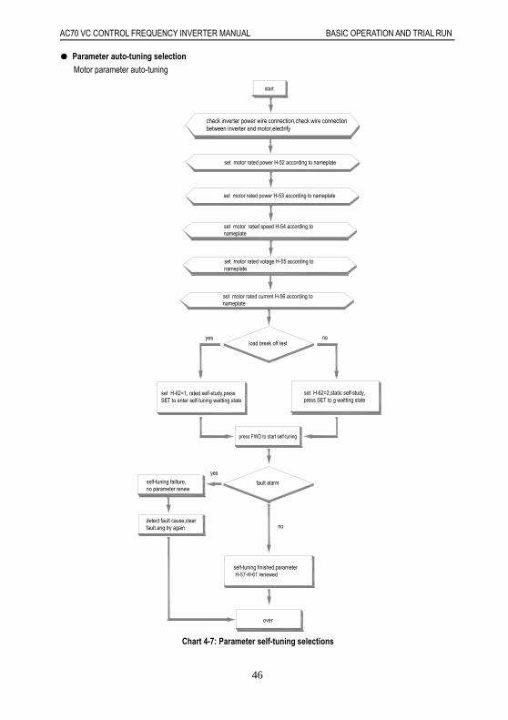
Parameter auto-tuning selection
Motor parameter auto-tuning
over
self-tuning finished,parameter H-57-H-61 renewed
detect fault cause,clear fault ang try again
self-tuning failture,no parameter renew
fault alarm
no
yes
press FWD to start self-tuning
set H-62=2,static self-study,press SET to g waitting state
set H-62=1, rated self-study,press SET to enter self-tuning waitting state
load break off testnoyes
set motor rated current H-56 according to nameplate
set motor rated speed H-54 according to nameplate
check inverter power wire connection,check wire connection between inverter and motor,electrify
start
set motor rated votage H-55 according to nameplate
set motor rated power H-52 according to nameplate
set motor rated power H-53 according to nameplate
Chart 4-7: Parameter self-tuning selections
AC70 VC CONTROL FREQUENCY INVERTER MANUAL BASIC OPERATION AND TRIAL RUN
47
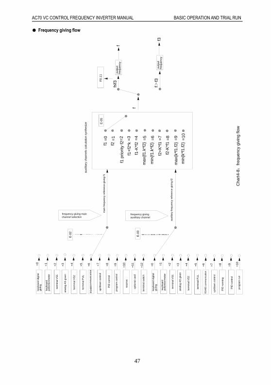
Frequency giving flow
pote
ntio
nmet
er
givi
ngcom
mun
icat
ion
pote
ntio
nmet
er
givi
ng rese
rve
optio
nal c
ard
keyb
oard
dig
ital
keyb
oard
term
inal
VS
1
term
inal
VS
2
anal
og A
S g
iven
term
inal
PU
L
RS
485
com
mun
icat
ion
prog
ram
con
trol
PID
con
trol
up/d
own
cont
rol
RS
485
term
inal
PU
L
anal
og A
S g
iven
term
inal
VS
2
keyb
oard
=4
=5
=6=2=1
=0
=3=8=7
=6
=9
=10=5=4
=3
keyb
oard
dig
ital
term
inal
VS
1
=0
=1
=2
=12=11
term
inal
sw
itch
=7
=10=9=8
up/d
own
cont
rol
PID
run
ning
PID
con
trol
prog
ram
run
f1+
f2*k
=3 =6=5=4=2
=1
=0
f1 p
riorit
y f2
f2
f1
E-0
5
f≤f3
f>f3
f
F0.
11
f
f3
f1-K
*f2
max
f1.
k*f2
min
f1.
k*f2
f2+
K*f
1=
7
=8
=9
=10
f2-K
*f1
max
k*f
1.f2
min
k*f
1.f2
E-0
2
E-0
3
frequency givingauxilliary channel
frequency giving mainchannel selection
auxi
lliar
y ch
anne
ls c
alcu
latio
n sy
nthe
size
freq
uenc
you
tput
outp
ut
freq
uenc
y
Cha
rt4-
8:fr
eque
ncy
givi
ng fl
ow
mai
n fr
eque
ncy
refe
renc
e gi
ving
f1
auxi
liary
freq
uenc
y re
fere
nce
givi
ng f2

AC70 VC CONTROL FREQUENCY INVERTER MANUAL BASIC OPERATION AND TRIAL RUN
48
Start/stop control flow
~
T
F
direct start
set frequencyconstant speed
F
start frequency accelerate
E-29
TE-28
braking and start frequency start
set frequency
start frequency
constant speed
accelerate
E-29DC baaking
E-38
E-28
start frequency hold time
T
speed track restart
E-53
energybaakingstop
decel eatel
E-34
F
constant speed
constant speed
stop output
E-36braking time
DC baakingstart frequency
E-37
frequencyset
free stop
connect
open
(Xi=X0 X6)
terminal function 6
Xi
=1
=0
stop
start
run command
Output frequencyconstant speed run
E-01=0
=1
=2
Chart 4-9: Start/stop control flow
AC70 VC CONTROL FREQUENCY INVERTER MANUAL BASIC OPERATION AND TRIAL RUN
49
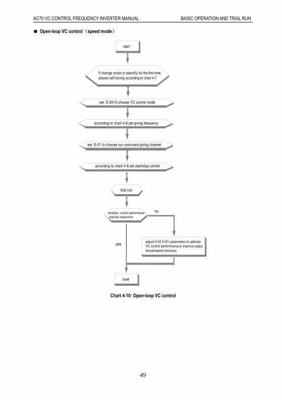
Open-loop VC control(speed mode)
over
yes
whether control performance reaches requirment
no
trial run
according to chart 4-9,set start/stop control
set E-01 to choose run command giving channel
according to chart 4-8,set giving frequency
set E-00=0,choose VC control mode
If change motor or electrify for the first time,please self-tuning according to chart 4-7
start
adjust H-52 H-61 parameters to optimize VC control performance,to improve output torque/speed accuracy
Chart 4-10: Open-loop VC control
AC70 VC CONTROL FREQUENCY INVERTER MANUAL FAULT DIAGNOSES AND PROCESSING
50
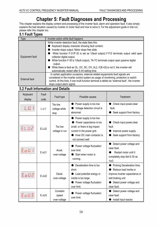
Chapter 5: Fault Diagnoses and ProcessingThis chapter explains the display content and processing of the inverter fault, alarm and operation fault. It also simplyexplains the bad situation caused by inverter or motor fault and how to solve it. For the adjustment guide in trial run,please refer this chapter too.
5.1 Fault TypesType Inverter action while fault happens
Equipment fault
While inverter detection fault, the state likes this: Keyboard display character showing fault content. Inverter stops output. Motor stops free slide. While function F-31/F-32 is set as 1(fault output),Y1/Y2 terminals output valid open
collector digital output. While function F-30 is 1(fault output), TA-TC terminals output open passive digital
output. While there is fault as OL, OC, SC, OV, UL2, if [E-43] is not 0, the inverter will
automatically restart after E-44 setting time.
External fault
In certain application occasions, external related equipments fault signals areconsidered in the inverter control system as usage of monitoring, protection or switchcontrol. At this time, if one multi function terminal is defied as “external fault”, the inverterstops output alarm signal.
5.2 Fault Information and DetailsKeyboard
display
Fault
codeFault type Possible causes Treatment
L.U.1
Too low
voltage while
stop
Power supply is too low
Voltage detection circuit is
abnormal
Check input power,clear
fault.
Seek support from factory.
E.LU2Too low
voltage in run
Power supply is too low
Power capacitance is too
small, or there is big impact
current in the power grid.
Inner DC main contactor is
not connect well
Check input power,clear
fault.
Improve power supply.
Seek support from factory.
E.oU1Accel.
over-voltage
Power voltage fluctuation
over limit.
Start when motor is
running .
Detect power voltage and
clear fault.
Restart motor until it
completely stop.Set E-30 as
1or2.
E.oU2Decel.
over-voltage
Deceleration time is too
short.
Load potential energy or
inertia is too large.
Power voltage fluctuation
over limit.
Prolong Deceleration time.
Reduce load inertia or
improve inverter capacitance or
add braking unit.
Detect power voltage and
clear fault.
E.oU3
Constant
speed
over-voltage
Power voltage fluctuation
over limit.
Detect power voltage and
clear fault.
Install input reactor.
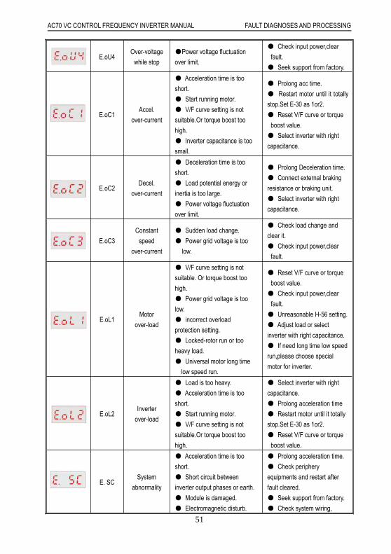
AC70 VC CONTROL FREQUENCY INVERTER MANUAL FAULT DIAGNOSES AND PROCESSING
51
E.oU4Over-voltage
while stop
Power voltage fluctuation
over limit.
Check input power,clear
fault.
Seek support from factory.
E.oC1Accel.
over-current
Acceleration time is too
short.
Start running motor.
V/F curve setting is not
suitable.Or torque boost too
high.
Inverter capacitance is too
small.
Prolong acc time.
Restart motor until it totally
stop.Set E-30 as 1or2.
Reset V/F curve or torque
boost value.
Select inverter with right
capacitance.
E.oC2Decel.
over-current
Deceleration time is too
short.
Load potential energy or
inertia is too large.
Power voltage fluctuation
over limit.
Prolong Deceleration time.
Connect external braking
resistance or braking unit.
Select inverter with right
capacitance.
E.oC3
Constant
speed
over-current
Sudden load change.
Power grid voltage is too
low.
Check load change and
clear it.
Check input power,clear
fault.
E.oL1Motor
over-load
V/F curve setting is not
suitable. Or torque boost too
high.
Power grid voltage is too
low.
incorrect overload
protection setting.
Locked-rotor run or too
heavy load.
Universal motor long time
low speed run.
Reset V/F curve or torque
boost value.
Check input power,clear
fault.
Unreasonable H-56 setting.
Adjust load or select
inverter with right capacitance.
If need long time low speed
run,please choose special
motor for inverter.
E.oL2Inverter
over-load
Load is too heavy.
Acceleration time is too
short.
Start running motor.
V/F curve setting is not
suitable.Or torque boost too
high.
Select inverter with right
capacitance.
Prolong acceleration time
Restart motor until it totally
stop.Set E-30 as 1or2.
Reset V/F curve or torque
boost value.
E. SCSystem
abnormality
Acceleration time is too
short.
Short circuit between
inverter output phases or earth.
Module is damaged.
Electromagnetic disturb.
Prolong acceleration time.
Check periphery
equipments and restart after
fault cleared.
Seek support from factory.
Check system wiring,
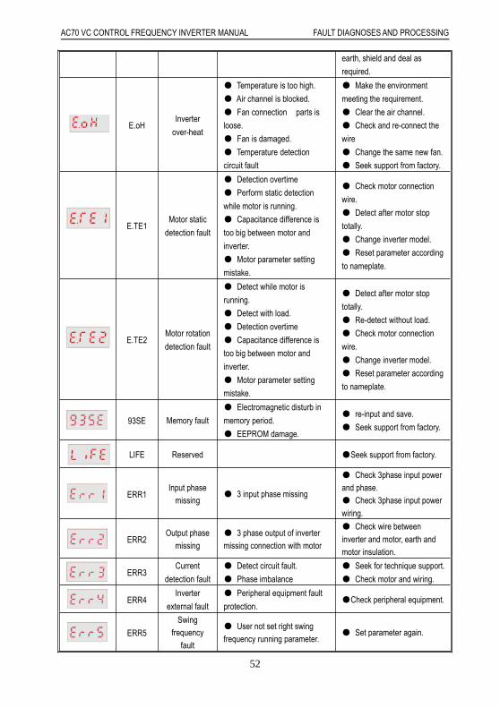
AC70 VC CONTROL FREQUENCY INVERTER MANUAL FAULT DIAGNOSES AND PROCESSING
52
earth, shield and deal as
required.
E.oHInverter
over-heat
Temperature is too high.
Air channel is blocked.
Fan connection parts is
loose.
Fan is damaged.
Temperature detection
circuit fault
Make the environment
meeting the requirement.
Clear the air channel.
Check and re-connect the
wire
Change the same new fan.
Seek support from factory.
E.TE1Motor static
detection fault
Detection overtime
Perform static detection
while motor is running.
Capacitance difference is
too big between motor and
inverter.
Motor parameter setting
mistake.
Check motor connection
wire.
Detect after motor stop
totally.
Change inverter model.
Reset parameter according
to nameplate.
E.TE2Motor rotation
detection fault
Detect while motor is
running.
Detect with load.
Detection overtime
Capacitance difference is
too big between motor and
inverter.
Motor parameter setting
mistake.
Detect after motor stop
totally.
Re-detect without load.
Check motor connection
wire.
Change inverter model.
Reset parameter according
to nameplate.
93SE Memory fault
Electromagnetic disturb in
memory period.
EEPROM damage.
re-input and save.
Seek support from factory.
LIFE Reserved Seek support from factory.
ERR1Input phase
missing 3 input phase missing
Check 3phase input powerand phase. Check 3phase input powerwiring.
ERR2Output phase
missing 3 phase output of invertermissing connection with motor
Check wire betweeninverter and motor, earth andmotor insulation.
ERR3Current
detection fault
Detect circuit fault.
Phase imbalance
Seek for technique support.
Check motor and wiring.
ERR4Inverter
external fault
Peripheral equipment fault
protection.Check peripheral equipment.
ERR5
Swingfrequency
fault
User not set right swingfrequency running parameter.
Set parameter again.
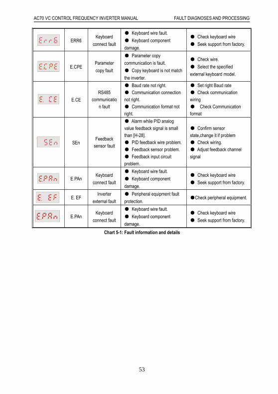
AC70 VC CONTROL FREQUENCY INVERTER MANUAL FAULT DIAGNOSES AND PROCESSING
53
ERR6Keyboard
connect fault
Keyboard wire fault.
Keyboard component
damage.
Check keyboard wire
Seek support from factory.
E.CPEParameter
copy fault
Parameter copy
communication is fault.
Copy keyboard is not match
the inverter.
Check wire.
Select the specified
external keyboard model.
E.CE
RS485communicatio
n fault
Baud rate not right. Communication connectionnot right. Communication format notright.
Set right Baud rate Check communicationwiring Check Communicationformat
SEnFeedback
sensor fault
Alarm while PID analogvalue feedback signal is smallthan [H-28]. PID feedback wire problem. Feedback sensor problem. Feedback input circuitproblem.
Confirm sensorstate,change it if problem Check wiring. Adjust feedback channelsignal
E.PAnKeyboard
connect fault
Keyboard wire fault.
Keyboard component
damage.
Check keyboard wire
Seek support from factory.
E. EFInverter
external fault
Peripheral equipment fault
protection.Check peripheral equipment.
E.PAnKeyboard
connect fault
Keyboard wire fault.
Keyboard component
damage.
Check keyboard wire
Seek support from factory.
Chart 5-1: Fault information and details

AC70 VC CONTROL FREQUENCY INVERTER MANUAL FAULT DIAGNOSES AND PROCESSING
54
5.3 Fault Diagnoses ProcessSystem fault diagnoses process
reduced or notvaluecan be
system fault
yes
yes
yes
yes
yes
yes
yes
yes
yes
yes
yesyesyes
yesyes yes
yes
yes
no
no
no
nono
no nonono
nono
nono
no
Clear short circuit Whether there is short circuit between outout terminal U/V/W and the motor
Short the cable or add outout reactor
Cable between output terminal U/V/W and motor is too long that leakage current cause inverter protection
Clear disturbance Is there serious electromagnetic disturbance?
While disconnect output wire and run,whether there is system fault alarm
Three phase outout voltage balance is ok or not?
Whether overload or not?
Connect load and operate as follows
Reduce load orenhance power
Display E.SC while start
Display E.SC while stop
Display E.SC while constant speed
Display E.SC while machine stop
Torque enhance value is suitable or not
Whether acceleration time is too short
Whether deceleration time is too short
Whether load change suddently
Torque enhance ACC time can beprolonged or not
Dec time can beprolonged or not
Reduce load changeor enhance power
Reduce Prolong setting timeCheck braking mode,seek tec support
Reduce load or enhance power
Inverter fault or misaction caused by noises.Pls find technic support

AC70 VC CONTROL FREQUENCY INVERTER MANUAL FAULT DIAGNOSES AND PROCESSING
55
Over current diagnoses process
Check braking mode and seek for technic support
Reduce load change or improve power
Reduce load change or improve power
Whether set longer decelerationtime
Set longer acceleration time or not?
Prolong setting time
Whether load changes suddently
May fault or misaction caused by noise.Please find technic support
Is deceleration time set too short?
Is acceleration time set too short?
Reduce the value
Whether torque enhance value is tooCan be reduced?
Reduce load or enhance power Whether load is too large
Whether short circuit between output terminal U/V/W and motor or earth circuit
Clear short circuit
nono
no
no no
nono
no
nono
no
no
yes
yes
yes
yesyes
yesyes
yes
yes
Constant speed over curent E.0C3
Decelerate over curent E.0C2
Accelerate over curent E.0C1

AC70 VC CONTROL FREQUENCY INVERTER MANUAL FAULT DIAGNOSES AND PROCESSING
56
Over voltage diagnoses process
ACC over voltage(OU1)
DCC over voltage(OU2)
Constant speed over voltage(OU3)
Stop state over voltage(OU4)
Fower votage in fixed range or not
no
no
no
no
no
no
no
no no nono
no
nono
no
no no no
yes yes yes
yes
yes
yes yes yes
yes
yes
yes
yes
yes
yes yes yes
Reduce power voltage into fixed range
Clear short circuit Phase or earth short cirsuit bwteen U/V/W and motor
Whether it stops while restart the motor
Whether act while load suddently changes to"0"
Whether DC circuit voltage of main loop is above protection value while act
Maybe inverter fault or misact.Plese seek for technic support
Whether act while suddently stop ACC Can prolong DCC time or not
prolongACC time can be prolong or not
Load intertia can be reduced or not
Whether used braking unit or DC braking function
Please check braking unit and seek for technic support
Use braking unit or DC braking function
Reduce
Stop motor and restart.Or DC braking,then start(E-30:1). Or speed track start(E-30:2)

AC70 VC CONTROL FREQUENCY INVERTER MANUAL FAULT DIAGNOSES AND PROCESSING
57
Supply voltage is too low
yes
yes
yes
yes yes
yes yes
no
no
no
no no
no
nono
Whether power off,including instant power offRestart after reset
Change fault componentand correct bad contact
Is there any fault component or bad contact in power circuit
Whether power voltage is in fixed range as required
Is there any big load start or stop under the same power supply
votage between DC circuit P+ and N- in main loop is over E-55 setting or not
Maybe inverter fault.please seek for technic support
Modify power supply system as required
Adjust E-55 setting
Voltage is too low while stop Lu1
Voltage is too low while running Lu2
Inner inverter over heat
Whether cooling fan works normally
Whether temperature display(C-09)is the same as the actual temperature
Whether load and carried frequency E-20 setting are too high
Whether air cooling channels are air-logged
Whether the temperature is within the fixed range as required
Change fan
Maybe temperature ditection circuit fault.please seek for technic support
Reduce load andcarried frequency
Clear the air-logged channel
Adjust the temperature to the fixed range as required
Maybe machine fault or misact.seek for technic support
no
no
nono
no
yes
yes
yes
yes
yes
Inner inverter overheat OH
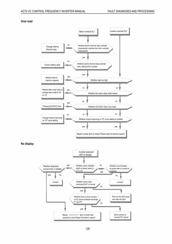
AC70 VC CONTROL FREQUENCY INVERTER MANUAL FAULT DIAGNOSES AND PROCESSING
58
Over load
yesyes
yes
yes
no
no
nono
no
nono
yes
yes
yes
no
no
Change torque improvingor V/F curve setting
Prolong ACC/DCC time
Restart after motor stop orchange start mode E-30to 1/2
Reduce load orimprove capacity
Correct setting value
Change externalthermal relay
Maybe inverter fault or misact.Please seek for technic support
Whether torque improving or V/F curve setting is suitable
Whether ACC/DCC time is too short
Whether the motor stops while restart
Whether load too high
Whether electric thermal relay overload relay setting E-50 is suiable
Whether electric thermal relay overload characteristic matches the motor overload characteristic
Motor overload OL1 Inverter overload OL2
No display
Inverter keyboardLED no display
Whether keyboardconnect line is reliable
Whether power indicater linght on power board is on or not
Whether circuit breaker at power side is connect to contacter
connectconnect Whether power input terminals R/S/T is normal
Whether there is short connect or DC reactor between terminals P1 and P+l
Maybe inverter fault or motor heat caused by noise.Please find technic support
Short connect or connect DC reactor
yes
yes
yes
yes
yes
no
no no
no
no
Find our the fault cause and clear the fault

AC70 VC CONTROL FREQUENCY INVERTER MANUAL FAULT DIAGNOSES AND PROCESSING
59
Motor heat
motor heat
Adjust torque imporoving value and V/F characteristic
Whether torque improving and V/F characteristic are suitable or not
Whether motor continuously run at low speed
Reduce load or improve capacity Whether load is too large Use special motor for inverter
Whether output terminals U/V/W output voltage /current three phase balance well
no
no
no
no
yes
yes
yes
yes
Maybe motor fault
Maybe inverter fault or motor heat caused by noise.Please find technic support
Motor does not rotate
no
no
no
no
no
no
yes
no
yes
yes
yesyes
yes
yes
yes
yes
should be reduced.If there is braking or brake uni,please check whether it is loose
Maybe motor is locked because of too large load.Load
value is suitableWhether torque improving Improve torque
improving valueMotor fault
Whether wiring is correct or not
Whether loadis too large
Is there voltage output on output terminal U/V/Wand three phase balance ok or not?
Correct connect
Maybe inverter fault .Please find technic support
It works after correct the upper frequency or given frequency
It works after checking the cause and slving the problem
Have input frequency signal or not
It works after checking the cause and solving the problem
Have input command signal or not
Whether keyboard displays fault information
Work after solving fault and reset
Motor does not work
Whether upper frequency limit E-10 or given frequency is lower than the start frequency E-28 setting
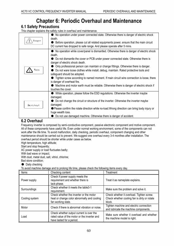
AC70 VC CONTROL FREQUENCY INVERTER MANUAL PERIODIC OVERHAUL AND MAINTENANCE
60
Chapter 6: Periodic Overhaul and Maintenance6.1 Safety PrecautionsThis chapter explains the safety rules in overhaul and maintenance.
No operation under power connected state. Otherwise there is danger of electric shockdeath. Before operation, please cut all related equipments power, ensure that the main circuitDC current has dropped to safe range. And please operate after 5 mins.
No operation while cover/panel is dismantled. Otherwise there is danger of electric shockdeath. Do not dismantle the cover or PCB under power connected state. Otherwise there isdanger of electric shock death. Only professional person can maintain or change fittings. Otherwise there is danger. Do not ware loose clothes while install, debug, maintain. Rated protective tools andsafeguard should be adopted. Tighten screw according to named moment. If main circuit wire connection is loose, thereis danger of overheat fire. Machine and motor earth must be reliable. Otherwise there is danger of electric shock iftouches the cover. While operation, please follow the ESD regulations. Otherwise the inverter maybedamaged. Do not change the circuit or structure of the inverter. Otherwise the inverter maybedamaged.Please confirm the rotate direction while no-load.Wrong direction can bring body injury orhuge wealth loss. Do not use damaged machine. Otherwise there is danger of accident.
6.2 OverhaulFrequency inverter is composed by semi-conductive component, passive electronic component and motive component.All of these components have useful life. Even under normal working environment, some of the components can notwork after the life time. To avoid malfunction, daily checking, periodic overhaul, component changing and othermaintenance should be carried out to prevent. We suggest one overhaul every 3-4 monthes after installation. Theoverhaul period should be shorter while under cases as below.High temperature, high altitude;Start and stop frequently;AC power supply or load fluctuates badly;With bad wave or impact;With dust, metal dust, salt, vitriol, chlorine;Bad store condition; Daily checkingTo avoid machine damage and to prolong life time, please check the following items every day.Items Checking content Treatment
Power supplyCheck if power supply meets therequirement and whether there islack-phase.
Treat it as nameplate explains.
Surroundings Check whether it meets the table3-1requirement.
Make sure the problem and solve it.
Cooling systemCheck whether the inverter or the motorheat or change color abnormally and coolingfan working state.
Check whether it overload. Tighten screw.Check whether cooling fan is dirty or rotateblock.
Motor Check if there is abnormal vibration or noise. Tighten machine and electric connectionand lubricate the machine components.
LoadCheck whether output current is over therated value of the motor or the inverter andhave lasted for a period.
Make sure whether it overload and whetherthe machine model is right.

AC70 VC CONTROL FREQUENCY INVERTER MANUAL PERIODIC OVERHAUL AND MAINTENANCE
61
:No operation under power connected state. Otherwise there is danger of electric shock death. Beforeoperation, please cut all related equipments power, ensure that the main circuit DC current has dropped to safe range.And please operate after 5 mins. Periodic overhaulUnder normal state, one overhaul every 3 or 4 months is ok. Please confirm the actual overhaul period according to themachine use condition and work circumstance while using the machine.Main circuitItems Checking content Treatment
Whole body Check insulated resistance;Check circumstance.
Tighten and change bad component;Clear and improve circumstance
Electric connection
Check whether the wire andconnector color changes, whether thereis disrepair , crack color change oraging in insulated layer.Check whether the connect terminalsare damaged or loose. Earth checking.
Change bad wire. Fasten terminals and change badterminals. Measure earth resistance and fastenearth terminals.
Mechanical connection Check if there is abnormal vibrationor noise or something is loose.
Tighten, lubricate and change the badmachine components.
semi-conductivecomponent
Check whether there is dust orrubbish. If there is obvious out change?
Clear Change damaged component
Electrolytic capacitor
Whether there is liquid leak, colorchange,or creak? Whether there issafety valve outcrop, inflation, creak orliquid leak.
Change damaged component
Peripheral equipment Peripheral equipment outlook andinsulation checking.
Clear and change damaged component
PCBBad smell,color change, bad rust andconnector checking.
Fasten connectorClear PCBChange bad PCB
Cooling system
Check whether the fan is damagedor blocked up.Whether rubbish and dust is stickedto the heat sink .Is air inlet/outlet blocked? Or is theresomething sticking to the inlet/outlet.
Clear Change damaged component
Keyboard Whether is it damaged? Checkwhether display is complete.
Change damaged component
Motor Check if there is abnormal vibrationor noise.
Tighten machine and electric connectionand lubricate the machine components.
:No operation under power connected state. Otherwise there is danger of electric shock death. Beforeoperation, please cut all related equipments power, ensure that the main circuit DC current has dropped to safe range.And please operate after 5 mins.
6.3 MaintenanceAll equipments and components have useful lifetime. Right maintenance can prolong the lifetime. But it can not avoiddamage. Please change the components before their lifetime over.
Component Useful lifetimeFan 2~3yearElectrolytic capacitor 4~5 yearPCB 8~10 year

AC70 VC CONTROL FREQUENCY INVERTER MANUAL PERIODIC OVERHAUL AND MAINTENANCE
62
FanWhile changing fan, please use original fan. You can contact Veichi company or the dealer. There are inverter modelswith many fans in one machine. To prolong these machines lifetime, you had better change all fans while changing thecooling fan. Fan change method:
1, Install the fan vertically into the cover as shown in the picture (the label should face the outside).
2, Press the elastic clip of the fan by finger toward the inner side and insert the leading terminal of the fan vertically by alittle strength.
3, Insert the two elastic clips of the fan cover vertically into the fan installation slots.

AC70 VC CONTROL FREQUENCY INVERTER MANUAL PERIODIC OVERHAUL AND MAINTENANCE
63
Fan dismantlement:
1, Pinch the two elastic clips of the fan and pull out. Then dismantle the fan cover.
2, Press the elastic clip of the fan by finger toward the inner side and pull out the leading terminal of the fan vertically bya little strength.
3, Poke the clips toward the outside and detach the fan from the cover by a little strength.
:1, No operation under power connected state. Otherwise there is danger of electric shock death. Beforeoperation, please cut all related equipments power, ensure that the main circuit DC current has dropped to safe range.And please operate after 5 mins.2, While the inverter is working, the heat sink temperature will be higher as the consumption. To prevent from scald,please do not touch the heat sink and do not change the fan until the temperature being safe.3, To ensure the best performance of the inverter, please use the original fan.Other componentsThe replacement of the other components has strict requirements on maintenance technique and product familiarity.And they can not be used without strict detection after replacement. So we do not suggest the user to replace the otherinner components. If they need to change indeed, please contact to the dealer or the sales department of Veichi electriccompany.
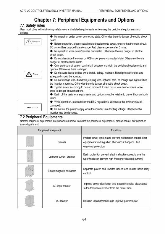
AC70 VC CONTROL FREQUENCY INVERTER MANUAL PERIPHERAL EQUIPMENTS AND OPTIONS
64
Chapter 7: Peripheral Equipments and Options7.1 Safety rulesUser must obey to the following safety rules and related requirements while using the peripheral equipments andoptions.
No operation under power connected state. Otherwise there is danger of electric shockdeath. Before operation, please cut all related equipments power, ensure that the main circuitDC current has dropped to safe range. And please operate after 5 mins. No operation while cover/panel is dismantled. Otherwise there is danger of electricshock death. Do not dismantle the cover or PCB under power connected state. Otherwise there isdanger of electric shock death. Only professional person can install, debug or maintain the peripheral equipments andoptions. Otherwise there is danger. Do not ware loose clothes while install, debug, maintain. Rated protective tools andsafeguard should be adopted. Do not change wire, dismantle jumping wire, optional card, or change cooling fan whilethe inverter is running. Otherwise there is danger of electric shock death. Tighten screw according to named moment. If main circuit wire connection is loose,there is danger of overheat fire. Earth of the peripheral equipments and options must be reliable to prevent human bodyinjury. While operation, please follow the ESD regulations. Otherwise the inverter may bedamaged. Do not cut the power supply while the inverter is outputting voltage. Otherwise theinverter may be damaged.
7.2 Peripheral EquipmentsNormal peripheral equipments are showed as below. To order the peripheral equipments, please consult our dealer orsales department.
Peripheral equipment Functions
Breaker
Protect power system and prevent malfunction impact other
equipments working when short-circuit happens. And
over-load protection.
Leakage current breakerEarth protection prevent electric shock(suggest to use the
type which can prevent high-frequency leakage current)
Electromagnetic contactorSeparate power and inverter indeed and realize basic relay
control.
AC input reactorImprove power side factor and isolate the noise disturbance
to the frequency inverter from the power side.
DC reactor Restrain ultra harmonics and improve power factor.

AC70 VC CONTROL FREQUENCY INVERTER MANUAL PERIPHERAL EQUIPMENTS AND OPTIONS
65
Input side noise filterReduce frequency inverter disturbance to the power and
reduce the power grid disturbance.
Braking resistor Passive energy consume unit of electric braking.
Consumption braking unit
Electric braking control unit, controlling the braking
resistance consume the regenerated electric power of the
motor efficiently.
Output side noise filter Reduce the output side wire electromagnetic disturbance.
Standby system Standby system for inverter malfunction.
Heat relay Protect the motor while over load.
0-phase reactorReduce electromagnetic disturbance of the frequency
inverter (suitable for input/output side).
Main loop surge absorbable unitRestrain surge voltage while main loop switch components
act.
Winding surge absorbable unit Restrain surge voltage when the AC contactor acts.

AC70 VC CONTROL FREQUENCY INVERTER MANUAL PERIPHERAL EQUIPMENTS AND OPTIONS
66
7.3 Use of Peripheral Equipments
Chart 7-1:Peripheral equipments connection figNote:Wiring breakerTo ensure wiring safe, protect power system and prevent malfunction expand to impact other equipment working whileshort-circuit happens, and protect while over-load, please do use wiring breaker between power supply and main looppower input terminals R,S,T.
: While choosing the breaker, the capacitance should be 1.5-2 times of the rated output current of thefrequency inverter. Please compare the time characteristic and protective time to the inverter (150% of the rated outputcurrent, one minute). Make sure there will be no skip.
: Before main loop wiring, make sure to cut the breaker and electromagnetic contactor. Otherwise there isdanger of electric shock.Leakage current breakerThe frequency inverter outputs peak voltage high-speed switch square wave. So there is high-frequency leakagecurrent. For earth protection to prevent electric shock and leakage current fire, please install leakage current breaker.Usually, one set frequency inverter will bring 100mA leakage current (while the power cable length is 1m). If the lengthprolongs 1m, there will be 5mA more leakage current. So please use leakage current breaker special for high frequencyleakage at the power input side of the frequency inverter. The factors which impact leakage current are as below:Capacitance of inverterCarrier frequencyMotor cable type and wire length
AC70 VC CONTROL FREQUENCY INVERTER MANUAL PERIPHERAL EQUIPMENTS AND OPTIONS
67
MI/RFI filterTo protect human body and inverter, please choose leakage current breaker which can use AC/DC power and can facehigh frequency leakage current. There should be one leakage current breaker with more than 200mA sensitive currentfor every frequency inverter. If the frequency inverter outputs different wave, the high frequency leakage current can behigher, which will lead to breaker fault. In this case, please take below treatments:Improve the sensitive current of the leakage current breakerReduce the carrier frequency of the inverterElectromagnetic contactorElectromagnetic contactor is a peripheral equipment what is set to actually separate power and inverter connection.While inverter protective function is acting or carrying out emergency stop operation, the main loop power can be cut byperipheral equipment. Please do not connect the electromagnetic switch or electromagnetic contactor to output circuit.Otherwise the inverter may be damaged. While the power recovers after instant stop, if it needs to prevent the inverterto auto-restart, please install electromagnetic contactor for control at the input side.AC input reactor and DC reactorTo restrain current sharp change and high hypo harmonic current, it needs to use AC input reactor and DC reactor. Itcan also improve power factor at the input side. In the following cases, AC input reactor or DC reactor must be used(use both will bring better effect).Need to restrain high hypo harmonic current and improve power side factor;Need to switch input phase capacitance;Frequency inverter is connected to large capacitance power transformer (600kVA above);Silicon-controlled converters such as DC motor driver are connected to the same power system.If user has higher requirement on other harmonic restraint, please connect the external DC reactor. Before connect theexternal DC reactor, make sure to dismantle the short connector between the terminals P1 and (+).Surge restrainerSurge restrainer is divided into winding surge restrainer and main loop surge restrainer according to the use position.Pls choose the right one which is suitable for the occasion. The aim of surge restrainer installation is to restrain thesurge voltage brought by switch components such as inductive load which is surrounding the frequency inverter(electromagnetic contactor, electromagnetic relay, electromagnetic valve, electromagnetic winding). Do not connect thesurge restrainer to the output side of the frequency inverter. Otherwise the frequency inverter will be damaged.。Input side noise filterRectifier bridge of the inverter is uncontrolled rectifier bridge. And input current is discontinuous impulse current. So theharmonic current noise signal, which flows to power wire from the inverter inner, may bring bad impact on thesurrounding machines (radio, phone, non contact switch, sensor). This time, we suggest to install input side noise filterto lighten the noise into the power wire. Besides, it can also reduce noise from the power wire into the frequencyinverter.
: Please use the noise filter special for the frequency inverter and the connection wire between the filter andthe inverter should be as short as possible.Output side noise filterThe frequency inverter outputs square wave with high-speed peak value voltage switch. So there is high-speed dv/dtconverter on the output cables that will produce a large number of radio disturbance and inductive signal. By installationnoise filter at the output side, the impact can be relieved. Please do not install the input-phase capacitance and thenoise filter to the output circuit. Otherwise there is danger of damage to the frequency inverter.0-phase reactor0-phase reactor is used to reduce the electromagnetic inductive disturbance of the frequency inverter, which is suitablefor the input side and output side. It equals to a three-phase common mode inductance. In actual use, according to theactual magnetic core size and cable specification, it is better to make sure 3-5 circles winding ratio to bring the bestperformance.Braking reactor or braking unitRenewed power consumption unit, please see the sixth part of the chapter three “electric installation”.Heat relayPlease install the heat relay at the output side of the frequency inverter. When the motor enters into overload state, itwill cut the power source to protect the motor. While using one frequency inverter to run one motor, there is no need toinstall heat relay. The motor overload protection current [E-49] of the frequency will work. While using one frequencyinverter to run multi-motors or the motor is run directly by the power grid, please install heat relay between thefrequency and the motor. While installing the heat relay, please design to cut the sequence control circuit of the MC atthe main loop input side by the connection spot of the relay or design to input the heat relay action into the frequencyinverter as the exterior malfunction.And please pay attention to the following tips to avoid heat relay fault and motoroverheating at low speed.

AC70 VC CONTROL FREQUENCY INVERTER MANUAL PERIPHERAL EQUIPMENTS AND OPTIONS
68
Run at low speedOne frequency inverter run multi motorsMotor cable is very longDetect malfunction mistakenly for carrier frequency is too highLow speed and heat relayIn normal case, the heat relay is suitable for the universal motor. While using the frequency inverter to run the universalmotor (standard motor), the motor current is 5-10% bigger, comparing with the commercial power supply. Besides, atlow speed, even in the motor rated current range, the cooling capability of the fan driven by the motor axis will reduce,which will bring motor overheat. So please set the motor overheat protection current [E-49] in the frequency inverter tobe valid.Motor cable is very longWhile the motor cable is very long and the carrier frequency is very high, impacted by the leakage current, the heatrelay may fail. To avoid it, please reduce the carrier frequency or set higher detection value of the heat relay. Beforeenhancing the detection value, do confirm whether there is other cause for the motor overheat. Otherwise there isdanger.

AC70 VC CONTROL FREQUENCY INVERTER MANUAL FUNCTION PARAMETER DETAILED SPECIFICATION
69
Chapter 8: Function Parameters Specification 8.1 Basic Parameters Specification
E-00 control method selection range:0-1 Default: 1 0: Open loop vector control without PG Also call sensorless vector control mode, are suitable for application one inverter drive one motor which need high performance control requirement. It can achieve fast torque response, wide speed control range and high torque output even under low speed without motor feedback. Note: It needs to perform motor auto tuning with configure motor parameters correctly before first time running with this control mode. 1: V/F control mode Adjusting the speed with V/F ratio, Use this mode for simple speed control and for multiple motor applications with low demands to dynamic response or speed accuracy. This control mode is also used when the motor parameters are unknown and Auto-Tuning cannot be performed. The speed control range is 1:40.
E-01 Running control command channel selection
Setting range:0-2 Default: 0
Uses for selecting inverter running, stop and running direction command input channel. 0: Operator keypad Running and stop of inverter control by forward running key FWD, reverse running or Job key REV/JOG and stop key STOP/RESET of operator keypad. When [E-08] parameters set to 0, REV/JOG is defined for reverse running, when [E-08] parameter set to 1, REV/JOG is defined for JOG running. 1: External terminal control Running, stop and rotation direction of inverter control by ON and OFF of FWD terminal or reverse terminal. Please refer to [F-08]. 2: RS485 Communications port control Running, stop and rotation direction of inverter control by given signal of RS485 control port. Note: STOP/RESET of keypad, reset command from control terminal or RS485 communication are all enabled when fault reset. Tips: 1. The running direction of inverter control is disabled by this command when programming control
and (VS2) terminal input bipolar adjustment, direction control is valid. 2. STOP/RESET key function is programmable, it can be defined emergency stop button function
when selecting external terminal control or RS495 control, refer to [F-07]; If use STOP/RESET button on keypad to stop inverter when selecting external terminal control, inverter will be stop and locked the external terminal command, it need to input external terminal stop command to unlock it, and then external terminal running command will be activated again. It is the same for RS485 communication control.
3. When selecting operator keypad control, direction control by external terminal takes is priority to control by keypad; it means that when reverse terminal and COM is on, if the direction command is changed by keypad, it will be keep the same original running direction after the terminal and COM is off.
E-02 Frequency reference given main channel selection
Setting range:0-12 Default: 1
It is used for selecting main frequency reference given of inverter, the frequency given will control or affect the output frequency of inverter; terminal (VS2) analog voltage signal and program control channel also will control the running direction of inverter directly. 0: Operator keypad digital Main frequency reference given by parameters [E-16] configuring: it is available to modify the [E-16] preset value via up/down arrow button on keypad when inverter in running status or stop state. 1: Potentiometer of keypad Main frequency given is determined by potentiometer of keypad. 2: Terminal VS1 analog voltage 0-10V Main frequency given determined by control terminal VS1 analog input, Regarding the relationship between input analog and frequency, filter time of input analog, Please refer to parameters in detail [F-41, F-42, F-43, F-56, F-57, F-58] parameters

AC70 VC CONTROL FREQUENCY INVERTER MANUAL FUNCTION PARAMETER DETAILED SPECIFICATION
70
3: Terminal AS analog current signal 4-20mA Main frequency given is determined and modified by ( AS) analog current input; Regarding the relationship between input analog and frequency, filter time of input analog, Please refer to parameters in detail [F-50, F-51, F-52, F-56, F-57, F-58]. 4: Terminal VS2 analog voltage -10-10V Main frequency given is determined and modified by control terminal VS2 analog input, Regarding the relationship between input analog and frequency, filter time of input analog, Please refer to parameters in detail [F-44, F-45, F-46, F-47, F-48, F-49, F-56F, -57, F-58] 5: Pulse train signal Main frequency given is determined and modified by control terminal (PUL) analog input, Regarding the relationship between input analog and frequency, please refer to parameters in detail [F-53, F-54, F-55, F-56, F-57, F-58] 6: RS485 communication port Main frequency given is determined by receiving signal of (A+) and (B-) of RS485 communication port. 7: Up and Down control Main frequency given is determined by increasing UP and decreasing (DOWN) terminal connecting or disconnecting( ON/OFF) with COM terminal; each of multi- terminal ( X1-X6) can be programmed by frequency UP terminal and DOWN terminal, refer to [F-01-F-06] in detail; Initial frequency of up and down terminal control can be configured, please refer to parameter [F-07] LED ten digit option and [F-70]. The acceleration and deceleration time of UP and Down control running is determined by acceleration/ deceleration time 1 [E13-E-14] setting; The rate of speed change of Up and Down terminal is determined by acceleration/ deceleration time 2 [F-24-F-25] setting.
8: General PID operation Select it use to set up general PID close loop control system. When it has been applied, the [H-16] present setting value can be modified by up and down arrow button of keypad. 9: Constant pressure PID control It can be used to set up constant pressure PID control ( constant pressure water supply system etc) close loop system, the [H-16] present setting value can be modified by up and down arrow button of keypad. 10: Program running Main frequency given and rotation direction are configured by inverter’s inner simple PLC process control. Up to 8 steps speed control is available, more detail refer to [E-13, E-14, F-09-F-16, F-24-F-29, H-32-H-51]. Run and stop command of program running determined by present setting value of running control command selection. When a step running time is set to 0, it means it will skip over this step when perform the program running. It is easy to set up the steps required of program running. When [E-46] parameter is set to 2 for forbidding reverse running, inverter will be run at 0 speed when arriving to a step which have been set to reverse running. Program running and multi-step speed operation are designed to achieve inverter variable-speed operation under a certain laws. Among the multi step operation, multi step speed switch over and rotation direction changing are achieved through the different combinations of external multi-step speed terminal with COM terminal ON and OFF. Multi step frequency, operation time, rotation direction can be defined by function parameters. Multi step speed control can be defined by each multi-function terminal, Please refer to [F-01-F-06] parameters. 11: Swing frequency run Output frequency periodically changes by pre-set decel & accel time. This function
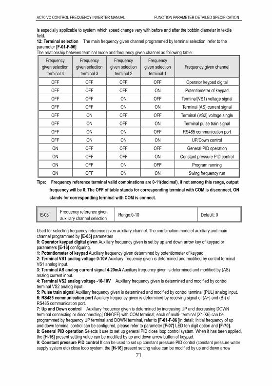
AC70 VC CONTROL FREQUENCY INVERTER MANUAL FUNCTION PARAMETER DETAILED SPECIFICATION
71
is especially applicable to system which speed change vary with before and after the bobbin diameter in textile field. 12: Terminal selection The main frequency given channel programmed by terminal selection, refer to the parameter [F-01-F-06] The relationship between terminal mode and frequency given channel as following table:
Frequency given selection
terminal 4
Frequency given selection
terminal 3
Frequency given selection
terminal 2
Frequency given selection
terminal 1 Frequency given channel
OFF OFF OFF OFF Operator keypad digital
OFF OFF OFF ON Potentiometer of keypad
OFF OFF ON OFF Terminal(VS1) voltage signal
OFF OFF ON ON Terminal (AS) current signal
OFF ON OFF OFF Terminal (VS2) voltage single
OFF ON OFF ON Terminal pulse train signal
OFF ON ON OFF RS485 communication port
OFF ON ON ON UP/Down control
ON OFF OFF OFF General PID operation
ON OFF OFF ON Constant pressure PID control
ON OFF ON OFF Program running
ON OFF ON ON Swing frequency run
Tips: Frequency reference terminal valid combinations are 0-11(decimal), if not among this range, output
frequency will be 0. The OFF of table stands for corresponding terminal with COM is disconnect, ON
stands for corresponding terminal with COM is connect.
E-03 Frequency reference given auxiliary channel selection
Range:0-10 Default: 0
Used for selecting frequency reference given auxiliary channel. The combination mode of auxiliary and main channel programmed by [E-05] parameters 0: Operator keypad digital given Auxiliary frequency given is set by up and down arrow key of keypad or parameters [E-16] configuring. 1: Potentiometer of keypad Auxiliary frequency given determined by potentiometer of keypad. 2: Terminal VS1 analog voltage 0-10V Auxiliary frequency given is determined and modified by control terminal VS1 analog input. 3: Terminal AS analog current signal 4-20mA Auxiliary frequency given is determined and modified by (AS) analog current input. 4: Terminal VS2 analog voltage -10-10V Auxiliary frequency given is determined and modified by control terminal VS2 analog input. 5: Pulse train signal Auxiliary frequency given is determined and modified by control terminal (PUL) analog input. 6: RS485 communication port Auxiliary frequency given is determined by receiving signal of (A+) and (B-) of RS485 communication port. 7: Up and Down control Auxiliary frequency given is determined by increasing UP and decreasing DOWN terminal connecting or disconnecting( ON/OFF) with COM terminal; each of multi- terminal (X1-X6) can be programmed by frequency UP terminal and DOWN terminal, refer to [F-01-F-06 ]in detail; Initial frequency of up and down terminal control can be configured, please refer to parameter [F-07] LED ten digit option and [F-70]. 8: General PID operation Selects it use to set up general PID close loop control system. When it has been applied, the [H-16] present setting value can be modified by up and down arrow button of keypad. 9: Constant pressure PID control It can be used to set up constant pressure PID control (constant pressure water supply system etc) close loop system, the [H-16] present setting value can be modified by up and down arrow

AC70 VC CONTROL FREQUENCY INVERTER MANUAL FUNCTION PARAMETER DETAILED SPECIFICATION
72
button of keypad.
10: Program running Main frequency given and rotation direction of inverter are configured by inverter’s inner
simple PLC process control. Up to 8 steps speed control is available, refer to [E-13, E-14, F-09-F-16, F-24-F-29,
H-32-H-52] Tips: Frequency main channel and frequency auxiliary channel can be set the same channel. In this case, the corresponding relationships between the frequency setting values and input signal are rather special, it need to consider the frequency main channel and auxiliary channel both characteristic at the same time. The combination of main and auxiliary frequency given still limited by upper frequency limit and lower frequency limit.
E-04 Frequency reference given channel gain
Range:0.01-5.00 Default:1.00
E-05 Frequency reference given channel combination mode Range:0-10 Default: 0
Frequency reference given channel gain: Uses to amplify or lessen the frequency input channel signal. Proportional regulating of frequency given both main and auxiliary channel is available. Frequency given channel combination mode: Uses for selecting frequency given main channel and auxiliary channel combination. K stands for [E-04] setting value, MAX means takes the bigger among the both channel, MIN means takes the smaller among the both. 0:Main channel is valid, auxiliary channel is invalid. 1:Auxiliary channel valid, main channel invalid 2:Both channel non “0” value valid, main channel priority 3:Main channel + ( K × auxiliary channel) 4:Main channel -(K × auxiliary channel) 5:MAX [main channel , (K × auxiliary channel)] 6:MIN [main channel , (K × auxiliary channel)] 7:Auxiliary channel + (K × main channel) 8:Auxiliary channel - (K × main channel) 9:MAX [(K × main channel), auxiliary channel] 10: MIN [(K × main channel), auxiliary channel] Tips: 1. Terminal (VS2) will be quite special in the multi-channel combination case. A. When (VS2) terminal don not activate the bipolarity adjustment and direct control function both ([F-48] set to 0), the combination mode determined [E-05] combination mode setting. B. When (VS2) terminal activate the bipolarity adjustment and direction control function both ([F-48] set to 1 ), ( VS2 ) terminal frequency given with bipolarity and frequency given in another channel implement signed arithmetic based on the combination mode selected, the absolute value is for frequency given, the signed determine the direction rotation of motor after calculation. C. When (VS2) activate the bipolarity adjustment but no direction control. ([F-48] set to 2 ). ( VS2 ) terminal frequency given with bipolarity and frequency given in another channel implement signed arithmetic based on the combination mode selected, the absolute value is for frequency given, the rotation direction depend on the[E-01] Running control command selection.
2. Swing frequency running, jog function and multi-step is disabled combine with auxiliary channel.
E-06 Upper LED monitor selection Range:0-7 Default:0
E-07 Lower LED monitor selection Rang:0-7 Default:1
Uses to select the monitoring items displayed in two LED on the keyboard respectively. In the monitoring status, the upper LED monitoring item and the lower monitoring item can be modify directly via SET key and SHIFT key. 0: Frequency reference Given 1: Output frequency 2: Output current 3: Input voltage 4: Output voltage 5: Machine speed 6: PID given 7: PID feedback value When there is only one LED on the keyboard, it is disable to modify the lower LED monitoring via the [E-07] and SHIFT key.

AC70 VC CONTROL FREQUENCY INVERTER MANUAL FUNCTION PARAMETER DETAILED SPECIFICATION
73
E-08 REV/JOG key of keypad function selection Range:0,1 Default: 0 Uses to select REV/JOG key of keypad function 0:Reverse This key is defined as reverse key(at this moment , keyboard functional indicator REV / JOG is not light). When the running control command selection is programmed as Operator keypad control , press this key , frequency inverter will perform reverse running. 1: Jog This key is defined as jog running key(at this moment , keyboard functional indicator REV / JOG is light). When the running control command selection is programmed as operator keypad control, press this key, frequency inverter will perform job running.
E-09 Maximum frequency Range:0.01-600.0Hz Default:50.00Hz
E-10 Upper limit frequency Range: lower limit frequency- maximum frequency
Default:50.00Hz
E-11 Lower limit frequency Range: 0.00-Upper limit frequency Default:0.00Hz
E-12 Lower limit frequency running mode Range:0,1 Default:1
Maximum frequency: Maximum frequency of [E-09] is the maximum allowable output frequency of inverter frequency, also is the reference point of acceleration and deceleration time setting. Upper limit frequency: Output frequency upper limit value which is set base on the highest allowable speed of machine. When the frequency given is higher than upper limit value, the actual running frequency is upper limit frequency. Lower limit frequency: Output frequency lower limit value of inverter. When the frequency given is lower than lower limit value, the actual speed depend on the [E-12] setting. Maximum frequency, upper limit frequency and lower limit frequency should be cautiously set base on the nameplate parameter of actual control motor and the need of the running conditions. Except of upper limit frequency and lower limit frequency, the output frequency while inverter running is limited by parameters setting of start-up frequency, free stop frequency, DC braking stop initial frequency, jump frequency and so on. The relationships between the maximum frequency, upper limit frequency and lower limit frequency is shown as the follow Fig.
Maximum frequency, upper limit frequency and lower limit frequency relationship. Fig.
Note: Lower limit frequency range is disabled for Jog function, only the upper limit frequency range is enable for Jog function. If the lower limit frequency operation mode [E-12] set to 0, the frequency given lower than the lower limit frequency, the inverter would be run at 0. If the lower limit frequency operation mode [E-12] set to 1, the frequency given lower than the lower limit frequency, the inverter would be run at lower limit frequency.

AC70 VC CONTROL FREQUENCY INVERTER MANUAL FUNCTION PARAMETER DETAILED SPECIFICATION
74
E-13 Acceleration time 1 Range:0.1-6500.0s Default:※
E-14 Deceleration time 1 Range:0.1-6500.0s Default:※
Acceleration time 1: when[E-15]LED tens digit place to 1, it defined required time of out frequency accelerates from 0.00Hz to maximum frequency[E-09], when[E-15]tens bit place to 0, it defined required time of output frequency accelerates from 0.00Hz to motor rated frequency, refer to[E-15]. Deceleration time 1: when [E-15] tens digit place to 1, it defined required time of out frequency decelerates from maximum frequency [E-09] to 0.00Hz , when [E-15] tens bit place to 0, it defined required time of output frequency decelerates from motor rated frequency to 0.00Hz, refer to [E-15].
Note: 1. In the general circumstance ( no special specify ), the acceleration/ deceleration time 1 is default
setting. The acceleration time is only valid for normal acceleration running, not including the DC
braking starting time and DC braking starting frequency holding time. The deceleration time only
for normal deceleration running, not includes DC braking stop time.
2. If activate the equidistant function, inverter would be accelerate base on the accel. time 1, but
decelerates based on equidistant stop decel. time setting. Refer to [E-15].
3. If need apply other accel. & decel. time group, should be configure by control terminals setting,
in the program running case, the accel./decel. time 1 is defined for first accel./decel. time, other 3
groups of accel./decel time setting is available, refer to [F-24-F-29]
4. Jog acceleration and deceleration time are programmed by [E-26, E27]separately.
E-15 Accel/decel mode selection Range:0000-0111 Default:0000
LED unit digit: accelerate /decelerate mode.
AC70 series sensorless vector provide 2 kinds accelerate /decelerate mode, both kinds is enable during normal
start, stop, forward and reverse running, accelerate, decelerate process.
0: linear accelerate Suitable for general load.
1: S curve S curve type accelerate/decelerate curve are designed for reducing noise and vibration, reduce
starting and stopping shock or decreasing torque required during low speed, accelerate in short time required
during high speed.ect during accelerate and decelerate process if need.
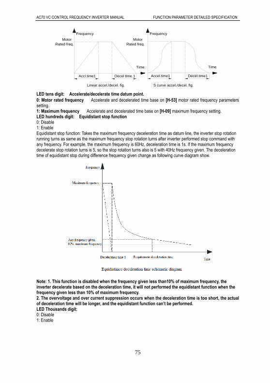
AC70 VC CONTROL FREQUENCY INVERTER MANUAL FUNCTION PARAMETER DETAILED SPECIFICATION
75
Accel.time1 Decel.time1
TimeTime
Frequency
Motor
Decel time.1Accl.time1
Linear accel./decel. fig.
Rated freq.Motor
Rated freq.
Frequency
S curve accel./decel. fig.
LED tens digit: Accelerate/decelerate time datum point. 0: Motor rated frequency Accelerate and decelerated time base on [H-53] motor rated frequency parameters setting. 1: Maximum frequency Accelerate and decelerated time base on [H-09] maximum frequency setting. LED hundreds digit: Equidistant stop function 0: Disable 1: Enable Equidistant stop function: Takes the maximum frequency deceleration time as datum line, the inverter stop rotation running turns as same as the maximum frequency stop rotation turns after inverter performed stop command with any frequency. For example, the maximum frequency is 60Hz, deceleration time is 1s. If the maximum frequency decelerate stop rotation turns is 5, so the stop rotation turns also is 5 with 40Hz frequency given. The deceleration time of equidistant stop during difference frequency given change as following curve diagram show.
Note: 1. This function is disabled when the frequency given less than10% of maximum frequency, the inverter decelerate based on the deceleration time, it will not performed the equidistant function when the frequency given less than 10% of maximum frequency. 2. The overvoltage and over current suppression occurs when the deceleration time is too short, the actual of deceleration time will be longer, and the equidistant function can’t be performed. LED Thousands digit: 0: Disable 1: Enable
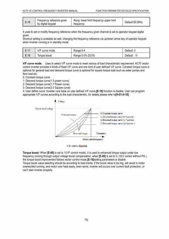
AC70 VC CONTROL FREQUENCY INVERTER MANUAL FUNCTION PARAMETER DETAILED SPECIFICATION
76
E-16 Frequency reference given by digital keypad
Rang: lower limit frequency-upper limit frequency Default:50.00Hz
It uses to set or modify frequency reference when the frequency given channel is set to operator keypad digital given. Shortcut setting is available as well, changing the frequency reference via up/down arrow key of operator keypad when inverter running or in standby mode.
E-17 V/F curve mode Range:0-4 Default: 0
E-18 Torque boost Range:0.0%-25.0% Default: ※
V/F curve mode: Uses to select V/F curve mode to meet various of load characteristic requirement. AC70 vector control inverter provides 4 kinds of fixed V/F curve and one kind of user defined V/F curve. Constant torque curve is optional for general load and descend torque curve is optional for square torque load such as water pumps and fans load.etc. 0: Constant torque curve 1: Descend torque curve(1.5 power curve) 2: Descend torque curve(1.7 Power curve) 3: Descend torque curve(2.0 Square curve) 4: User define curve :Inverter runs base on user defined V/F curve,[E-18] function is disable, User can program appropriate V/F curves according to the load characteristic, for details please refer to[H-01-H-10].
Torque boost: When [E-00] is set to 1(V/F control mode), it is used to enhanced torque output under low frequency running through output voltage boost compensation, when [E-00] is set to 0 ( OLV control without PG ), the torque boost improvement follows vector control mode,[E-18]setting parameters is disable. Torque boost value selecting should be according to load inertia. If the boost value is too big, will result in motor overexcited running, and motor over heat easily, even worst, inverter will occurs over current fault protection, or can’t start inverter properly.
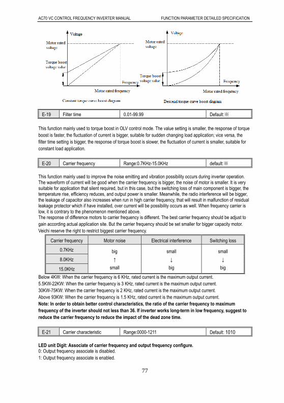
AC70 VC CONTROL FREQUENCY INVERTER MANUAL FUNCTION PARAMETER DETAILED SPECIFICATION
77
E-19 Filter time 0.01-99.99 Default:※
This function mainly used to torque boost in OLV control mode. The value setting is smaller, the response of torque boost is faster, the fluctuation of current is bigger, suitable for sudden changing load application; vice versa, the filter time setting is bigger, the response of torque boost is slower, the fluctuation of current is smaller, suitable for constant load application.
E-20 Carrier frequency Range:0.7KHz-15.0KHz default:※ This function mainly used to improve the noise emitting and vibration possibility occurs during inverter operation. The waveform of current will be good when the carrier frequency is bigger, the noise of motor is smaller. It is very suitable for application that silent required, but in this case, but the switching loss of main component is bigger, the temperature rise, efficiency reduces, and output power is smaller. Meanwhile, the radio interference will be bigger, the leakage of capacitor also increases when run in high carrier frequency, that will result in malfunction of residual leakage protector which if have installed, over current will be possibility occurs as well. When frequency carrier is low, it is contrary to the phenomenon mentioned above. The response of difference motors to carrier frequency is different. The best carrier frequency should be adjust to gain according actual application site. But the carrier frequency should be set smaller for bigger capacity motor. Veichi reserve the right to restrict biggest carrier frequency.
Carrier frequency Motor noise Electrical interference Switching loss
0.7KHz big
↑
small
small
↓
big
small
↓
big
8.0KHz
15.0KHz
Below 4KW: When the carrier frequency is 6 KHz, rated current is the maximum output current. 5.5KW-22KW: When the carrier frequency is 3 KHz, rated current is the maximum output current. 30KW-75KW: When the carrier frequency is 2 KHz, rated current is the maximum output current. Above 93KW: When the carrier frequency is 1.5 KHz, rated current is the maximum output current. Note: In order to obtain better control characteristics, the ratio of the carrier frequency to maximum frequency of the inverter should not less than 36. If inverter works long-term in low frequency, suggest to reduce the carrier frequency to reduce the impact of the dead zone time.
E-21 Carrier characteristic Range:0000-1211 Default: 1010 LED unit Digit: Associate of carrier frequency and output frequency configure. 0: Output frequency associate is disabled. 1: Output frequency associate is enabled.

AC70 VC CONTROL FREQUENCY INVERTER MANUAL FUNCTION PARAMETER DETAILED SPECIFICATION
78
When the associate of carrier frequency of output frequency is enable, the inverter will adjust the carrier frequency automatically according the output frequency, this function can improve the torque performance in low speed, if combine with torque boost function will make performance better in low speed. LED tens digit: Associate of carrier frequency and module temperature configure. 0: Module temperature associate is valid. 1: Module temperature associate is invalid. Inverter will reduce the carrier frequency when the temperature of inverter rise, this function can reduce the switching loss to prevent over heat fault occurs. LED hundreds digit: PWM mode selection 0: Fixed PWM mode The noise frequency of motor is fixed. 1: Random PWM mode 1 This mode enables the harmonic spectrum of inverter output voltage evenly distributing in a wide frequency range to inhibit the electrical noise and vibration effectively, carrier frequency is 2.0KHz. 2: Random PWM mode 2 As the same as above mention, but carrier frequency is 2.5KHz. LED thousands digit: Inhibition of shock. 0: Inhibition of shock is disabled. 1: Inhibition of shock is enabled.
E-22 V/F slip compensation Range:0%-200% Default: 100% This function enables output frequency of inverter automatically regulate with the load of motor changing. This can compensate slip frequency of motor dynamically, it enables the motor maintaining a constant rotation speed to reduce the load changing impacts on the motor speed effectively.
If cooperate with auto torque boost function, the torque performance in low frequency characteristic of inverter will be significantly improved. The value of slip frequency compensation should be set base on motor rated slip, should not set the value of compensation too large.
E-23 Energy saving mode selection Range: 0000-0011 Default: 1000 LED unit digit: Auto energy saving selection 0: disable 1: enable During running process, inverter can automatic calculate the best output voltage to load according to the load condition for energy saving. Energy saving function works by reducing output voltage, enhancing the power factor and improve motor efficiency. LED tens digit: V/F slip compensation 0: Disable

AC70 VC CONTROL FREQUENCY INVERTER MANUAL FUNCTION PARAMETER DETAILED SPECIFICATION
79
1: Enable If only activate the slip compensation function in V/F control mode, this parameters used for selecting slip compensation function. LED Hundreds digit: Reserve LED Thousands digit: Over modulation 0: Over modulation allowed 1: Over modulation not allowed
E-24 Voltage auto regulation function Range:0,1,2,3 Default:2 0: Disable 1: Enable in full process 2: Disable only in deceleration Output voltage auto regulation function that is AVR function. When AVR function disable, the output voltage change vary with input voltage. When the AVR enable, the output voltage will keep in setting value as long as the minimum of fluctuation input voltage bigger than output voltage setting (Motor rated voltage). When the power supply voltage less than rated output voltage, the output voltage will decrease follow with input voltage.
E-25 Jog frequency Range:0.50Hz-maximum frequency Default:5.00Hz
E-26 Jog acceleration time Range:0.1-6500.0s Default:2.0s
E-27 Jog deceleration time Range:0.1-6500.0s Default:2.0s
The jog frequency function has the highest control priority (terminal jog function). It means in any condition, when jog command is valid, the inverter immediately run from the current running frequency to the jog frequency based on jog accelerates/decelerates time. The jog accelerates/decelerates time is defined as same as accelerates/decelerates time, which can be configured by the keyboard, control terminal or job function control command of RS485. Note: The setting value of the jog running frequency is only limited by the upper limit frequency. Only the priority of job terminal control free from limitation of running control command channel. Other jog command have priority only under the same running control command channel, such as the keypad job command is enabled only in the operator keypad control running.
E-28 Start frequency Range:0.00-60.00Hz Default:0.50Hz
E-29 Start frequency holding time Range time:0.0-20.0s Default:0.0s
Start frequency: The initial output frequency when inverter starting. The large starting torque is available if the starting frequency is properly set. It can gain high impact when starting instantaneous for some load that has a bigger static friction force in static status. But it will result in a trip if the value is set to big. Start frequency holding time: It means the inverter keeps running time under starting frequency.

AC70 VC CONTROL FREQUENCY INVERTER MANUAL FUNCTION PARAMETER DETAILED SPECIFICATION
80
Note: The frequency output is 0 when the frequency given less than starting frequency during the
acceleration process.
E-30 Starting mode selection Range:0000-1102 Default:※000
LED unit digit: Starting mode selection. 0: Starts from starting frequency Inverter starts with [E-28] starting frequency given and [E-29]starting frequency holding time given. Applicable for application which has big static friction torque, light load inertia, Or suit to work together with machinery that equipped external mechanical braking. That is occasion where the shaft of motor can maintain still before start, but after motor stop. 1: DC braking first, and then start from starting frequency Perform DC braking function first with DC braking voltage [E-35] and DC braking time [E-38] to feed motor a center DC braking energy (Electromagnetic braking), and then starts with starting frequency. Applicable for occasion there are forward or reverse running of small inertia load in stop status. 2: Restart after speed searching Inverter try to detect the speed of a rotating motor shaft that is driven by external forces first and start the motor operation directly from the detected speed to frequency given according acceleration /deceleration time. Note: During forward/reverse switching process in normal operation, and perform accel/decel process after frequency given modifying, both start from 0.0Hz or stop to 0.0Hz. LED tens digit: Reserve LED hundreds digit: Speed search direction 0: Speed search performs only in running direction 1: Bi-speed search performs LED thousands digit: Speed search mode 0: Software speed search 1: Hardware speed search
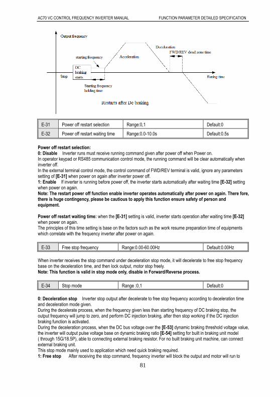
AC70 VC CONTROL FREQUENCY INVERTER MANUAL FUNCTION PARAMETER DETAILED SPECIFICATION
81
E-31 Power off restart selection Range:0,1 Default:0
E-32 Power off restart waiting time Range:0.0-10.0s Default:0.5s
Power off restart selection: 0: Disable Inverter runs must receive running command given after power off when Power on. In operator keypad or RS485 communication control mode, the running command will be clear automatically when inverter off. In the external terminal control mode, the control command of FWD/REV terminal is valid, ignore any parameters setting of [E-31] when power on again after inverter power off. 1: Enable If inverter is running before power off, the inverter starts automatically after waiting time [E-32] setting when power on again. Note: The restart power off function enable inverter operates automatically after power on again. There fore, there is huge contingency, please be cautious to apply this function ensure safety of person and equipment. Power off restart waiting time: when the [E-31] setting is valid, inverter starts operation after waiting time [E-32] when power on again. The principles of this time setting is base on the factors such as the work resume preparation time of equipments which correlate with the frequency inverter after power on again.
E-33 Free stop frequency Range:0.00-60.00Hz Default:0.00Hz When inverter receives the stop command under deceleration stop mode, it will decelerate to free stop frequency base on the deceleration time, and then lock output, motor stop freely. Note: This function is valid in stop mode only, disable in Forward/Reverse process.
E-34 Stop mode Range :0,1 Default:0 0: Deceleration stop Inverter stop output after decelerate to free stop frequency according to deceleration time and deceleration mode given. During the decelerate process, when the frequency given less than starting frequency of DC braking stop, the output frequency will jump to zero, and perform DC injection braking, after then stop working if the DC injection braking function is activated. During the deceleration process, when the DC bus voltage over the [E-53] dynamic braking threshold voltage value, the inverter will output pulse voltage base on dynamic braking ratio [E-54] setting for built in braking unit model ( through 15G/18.5P), able to connecting external braking resistor. For no built braking unit machine, can connect external braking unit. This stop mode mainly used to application which need quick braking required. 1: Free stop After receiving the stop command, frequency inverter will block the output and motor will run to

AC70 VC CONTROL FREQUENCY INVERTER MANUAL FUNCTION PARAMETER DETAILED SPECIFICATION
82
stop freely. Generally coordinate external mechanical braking to achieve quick stop when this stop mode has been selecting.
E-35 DC braking voltage Range:0%-150% Default:50%
E-36 DC braking time when stop Range:0.0-30.0s Range:0.0s
E-37 DC braking starting frequency when stop Range:0.00-60.00Hz Range:0.00Hz
E-38 DC braking time when start Range:0.0-10.0s Range:0.0s
DC braking voltage: The value of voltage which is injected to motor when executing DC braking function. The value of voltage benchmark against the input rated current of inverter. This function can output torque under zero speed. Generally, it uses to improve the stop accuracy and realize quick stop, but it can’t be apply for normal deceleration. The inverter will stop output once DC braking has been performed. If the DC raking current set to big, over current fault occurs easily during stop. DC braking time when stop: DC braking current lasting time when inverter stops, if the braking time is set to 0, it means the DC braking function is disabled.
DC braking starting frequency when stop It means when inverter decelerated to this frequency, the inverter will stop output, and perform the DC braking function. If the output frequency less than DC braking starting frequency when stop during running process, the inverter will stop output, start DC braking function when receiving the stop command. The inverter will start DC braking, and the output frequency jump to zero if the frequency given less than DC braking staring frequency when stop during the deceleration process. The DC braking staring frequency when stop should be set smaller when there are no strictly requirement for stop. When the DC braking staring frequency when stop[E-37]parameters setting smaller than free stop frequency [E-33] setting, the inverter will decelerate to free stop frequency, and then stop output execute DC braking. DC braking time when start: It refer to DC braking voltage lasting time when stop, Only if [E-30] parameters unit digit set to 1, the DC braking function will be enabled. When the braking time set to 0.0s, not perform DC braking function
E-39 Jump frequency 1 Range:0.00-600.0Hz Default:0.00Hz
E-40 Jump frequency 2 Range:0.00-600.0Hz Default:0.00Hz
E-41 Jump frequency 3 Range:0.00-600.0Hz Default:0.00Hz
E-42 Jump frequency range Range:0.00-5.00Hz Default:0.00Hz
The Jump frequencies are frequency ranges at which the drive will not operate. The drive can be programmed with three separate Jump frequencies to avoid operating at speeds that cause resonance in driven machinery. If the frequency reference falls within a Jump frequency dead band, the drive will clamp the frequency reference just below the dead band and only accelerate past it when the frequency reference rises above the upper end of the dead band. Jump frequency range: The frequency up and own jumping bias base on jump frequency

AC70 VC CONTROL FREQUENCY INVERTER MANUAL FUNCTION PARAMETER DETAILED SPECIFICATION
83
Setting value
Jumping range
Jumping range
Jumping range
The setting value after jumping
Jumping frequency 1
Jumping frequency 2
Jumping frequency 3
Jumping frequency and jumping range relationship
Note: 1. The output frequency still will pass the jumping range during acceleration or deceleration. Make sure the parameters don't overlap or inset setting.
2. Jumping frequency is disabled for jog, multi-step speed and swing frequency.
E-43 Number of auto restart attempts
Range:0-3 Default:0
E-44 Fault auto reset waiting time Range:0.1-20.0s Default:1.0s
Number of automatic fault reset: 0: Disable, The auto reset function is disabled, reset only by manual. 1—3: Enable, 1-3 parameters used for defining the numbers of auto reset. (The maximum time of auto reset is enabled) The inverter may be trip to stop cause by fluctuation of grid and other accidents reason during operation. Auto reset for overload, over current, system abnormal, overvoltage, under voltage. etc fault occurs is allowable to restart inverter operation ensure system working continuously. Inverter will restart with speed search restart mode during auto reset. If the auto reset fails to restart during the setting give numbers, the fault protection will be activate, inverter stop output. The maximum of auto reset number setting is 3, the reset numbers will be recount after inverter running normally for 10 minutes, the record times clears automatically. Suggest configure number of auto reset to 1 times will be better. The fault output terminal can be set disable or enable during fault auto reset process. Refer to [F-30,F-31,F-32] Fault auto reset waiting time: Uses for defining the waiting time from fault occurs to reset attempts. Note: 1. This function only enable for overload, over current, system abnormal, over voltage, under voltage during running, disable for other fault happen. 2. Reset can’t make if fault fail to solve, no reset for the temperature of inverter over 70 Tips: Users must be cautious to consider the start characteristic of the mechanical devices in crane, lifting application. It should be cautious in using this function for application which can’t start with load or the alarm will come out immediately when inverter stop output.
E-45 Machine warm up time Range:0.0-6500s Default:0.0s
Inverter enables command operation after machine warm up time, once power supply switch to inverter. It displays count down in seconds after switch on.
E-46 Running direction selection Range:0-2 Default:0
0: Consistent with the default direction Actual rotation direction is the same with the requirement. The actual direction don’t change.

AC70 VC CONTROL FREQUENCY INVERTER MANUAL FUNCTION PARAMETER DETAILED SPECIFICATION
84
1: Opposite to the default direction Actual rotation direction is opposite to the requirement. The actual direction will be change. 2: Reverse running forbidden When this parameter is set as prohibition, all the reverse command from Running control command selection (operator keypad, external terminal, RS485 communication, bipolar VS2 and program running) are invalid. The setting will not be modified after the factory default setting. Note: 1. When the reverse running forbidden is selected, when the bipolar control receiving the reverse frequency command, the inverter will be operation with 0 speed, the case is the same, inverter will be operate with 0 speed during program running control if there are some certain step speed reverse direction are set.
2. All reverse command will be auto turn to running command, running with forward direction.
E-47 FOR/REV dead zone time Range:0.0-10.0s Default:0.0s
The function defined the transient waiting time from forward to reverse or from reverse to forward during 0Hz. FOR/REV dead zone time special designed for big inertia load application which has mechanical dead zone required.
E-48 Cooling fans running selection Range:0,1,2 Default:※ Uses select cooling fan running mode. 0: Fan runs when inverter switch on. Cooling fan stop when under voltage condition, it runs when power supply is stable. 1: Relates with temperature during inverter stop mode, fan runs when inverter running Fan stop or not is relate to temperature of module during stop mode, fan would operate when the temperature is above 45, stop when module temperature lower 40. Fan runs immediately when inverter receives a run command. 2. Fan stop during inverter stop mode, relates with temperature during inverter running. Fan stop or not is related to temperature of module during inverter running mode, fan runs when the temperature of module is above 45, stops when temperature of module is lower than 40. Fan stops always during inverter stop mode. Note: Use this function correctly enable extend fans working life.
E-49 Inverter protecting mode selection Range:0000-1111 Default:0※11
LED unit digit: Overvoltage protecting selection during deceleration 0: Disable 1 Enable

AC70 VC CONTROL FREQUENCY INVERTER MANUAL FUNCTION PARAMETER DETAILED SPECIFICATION
85
During the inverter deceleration, the energy generated by motor feedback to inverter inside due to load inertia effect, which will cause the voltage of inverter over the maximum voltage threshold. The over voltage protecting occurs if without any measure. When overvoltage protection is activated, the inverter deceleration stops (output frequency stop descend) when detecting the DC bus voltage over[E-53]setting, deceleration only allow to continue until the DC bus voltage is lower than the protective value. Note: It will cause the stop time from deceleration given to stop to be longer if the stall protection is active.
LED ten digit: Output phase missing protection 0: Disable 1: Enable Used for detecting if output wiring missing when inverter power on, if there are any output phase missing, the Err2 occurs, fault output terminal will be activated. LED hundred digit: Input phase missing protection 0: Disable 1: Enable Inverter performs phase missing detecting for 3 phase AC input, if any phase missing, Err1 will occurs, and stop output. Motor will carry out free stop, the fault output terminals will be activate. LED thousand digit: Inverter overload, over heat protect mode selection. 0: Free stop 1: running with current limit This parameter will determine the protection mode when overload, over heat occurs. Free stop means that output of inverter stop immediately, and active ‘OL2’and ‘OH’ fault alarm. The running with current limit is that inverter running is based on output current limit. If the current over the current limit value, the output frequency will be decreased to reduce the load current. The output terminal [F-30-F-32]can be used to output pre-alarm signal when overload happens. Current limit value during overvoltage and overheat=rated current ×100%
E-50 Coefficient value of electronic thermal
Range:30%-120% Default:0%
Motor will generate heat seriously in a long time overload running. This parameter is used to set coefficient of thermal relay of motor in inverter. When the rated current of motor is equal to rated current of inverter, the value can be set 100%, when the rated current of motor can’t match the rated current of inverter, this parameter value can be set for motor overheat protection properly. The factory default setting of overload capacity of inverter as follows: G type: 150%× rated current for 1 minute. F type: 120%× rated current for 1 minute. The parameters setting value can follow below formula: Coefficient value of electronic thermal=rated current/ rated output current of inverter Note: This function would fail when one inverter drives multiple motors in parallel. Please install the thermal relay before motor input to protect motor effectively
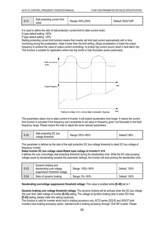
AC70 VC CONTROL FREQUENCY INVERTER MANUAL FUNCTION PARAMETER DETAILED SPECIFICATION
86
E-51 Stall protecting current limit value Range:100%-250% Default:160G/120P
It is used to define the ratio of stall protection current limit to rated current motor. G type default setting: 160% P type default setting: 120% Stalling protecting current limit function means that inverter will limit load current automatically with in time monitoring during the acceleration, make it lower than the limit setting, (Stops acceleration or lower the output frequency to achieve the value of output current controlling), to protect big current occurs result in fault alarm trip. This function is suitable for application where has big inertia or load fluctuates severe particularly.
This parameters datum line is rated current of inverter. It will extend acceleration time longer. It means the current limit function is activated if the frequency can’t accelerate to set value or frequency given, but fluctuates in the fixed frequency range. Please reduce the load or adjust the some relevant parameters.
E-52 Stall protecting DC bus voltage threshold Range:105%-160% Default:138%
This parameter is defined as the ratio of the stall protection DC bus voltage threshold to rated DC bus voltage of frequency inverter. Rated inverter DC bus voltage value=Rated input voltage of inverter×1.414 It defines the over overvoltage stall protecting threshold during the deceleration time. While the DC side pumping voltage cause by decelerating exceeds this parameter settings, the inverter will auto-prolong the deceleration time.
E-53 Dynamic braking and decelerating over voltage suppression threshold voltage
Range: 105%-160% Default: 130%
E-54 Ratio of dynamic braking Range: 0%-100% Default: 100%
Decelerating overvoltage suppression threshold voltage: This value is enabled while [E-49] set to 1 Dynamic braking over voltage threshold voltage: The dynamic braking will be activate when the DC bus voltage rise over than rated voltage of inverter [E-53] setting. The voltage of dynamic braking stop is lower 20V than [E-53] setting, please make this setting cautiously. This function is valid for inverter which built in braking accessory only, AC70 series 22G/30 and 30G/37 both inverters have braking accessory option, standard built in braking accessory through 15G/18P inverter. Please

AC70 VC CONTROL FREQUENCY INVERTER MANUAL FUNCTION PARAMETER DETAILED SPECIFICATION
87
select braking unit or braking accessory if need for other model. Ratio of dynamic braking: This parameter defines the average of voltage which applied on the braking resistor when braking unit effecting. The voltage applied on the braking resistor is PWM wave, the duty cycle is equal to ratio of dynamic braking. The ratio bigger, energy release faster, the braking effects better, and the same time the more energy consumes on the braking resistor. Selecting the braking resistor value, power and braking effects should take comprehensive consideration to set this parameter.
E-55 DC bus under voltage protecting value Range:60%-90% Default: 65%
This parameter defines the DC bus side lower limiter voltage while inverter in normal working condition. It allow to set under voltage protecting levels lower to ensure inverter normal working for power grid lower situation. Note: The output torque will be reduced when the power grid voltage is low. For the constant power load and constant torque load application, the too low power grid voltage will increase input and output current, which will reduce the inverter ruing reliability.
E-56-E-58 Reserve
E-59 Rotation speed display scale factor Range:0.1-2000.0 % Default:100.0%
It uses to set the display factor of keypad monitor, 100.0% correspond with motor rated speed. The upper limit machine speed is 65000 RPM.
E-60 Ratio of inverter output voltage Range:50%-110% Default:100%
Ratio of output voltage to rated voltage of inverter. This function uses to coordinate the output voltage to meet various types of V/F characteristic requirement. Output voltage of inverter = rated voltage of inverter ×Ratio of inverter output voltage
E-61 G/P type setting Range:0 ,1 Default:0
When reset the factory setting, this parameter setting values will not be changed. 0:G model, it is suitable for constant torque load. 1:P model, it is suitable for variable torque(such as fan, water pump load). The AC70 series frequency inverter adopts G/P in one mode. The power of the motor adaptability used in the constant torque load (G model) is lower one grade than that used in fan, water pump load (P model)
E-62 Speed search stability keeping time
Range:0.20-10.00s Default:0.600s
This parameter defines the time of inverter try to run stably when inverter detected the frequency point during speed search process. Inverter accelerates to frequency set point with acceleration time given. For the big inertia load, extend the speed search stability keeping time can reduce the instantaneous impact current of speed search start.

AC70 VC CONTROL FREQUENCY INVERTER MANUAL FUNCTION PARAMETER DETAILED SPECIFICATION
88
E-63 Parameters change protection Range:0-2 default: 0
0:All the parameters changing allowed Except for the parameters only for inquiry, any other parameters can be changed (Note: Some parameters only can be changed in the stop state, some parameters can not be changed in any condition). 1: Only keyboard digital given parameter changing allowed Except for the keyboard digital given frequency and keyboard number PID given quantitative parameter, any other parameter don’t allow changing. 2: All the parameters prohibit changing All the parameters of frequency inverter unchangeable; When users need to change the parameter, They have to change this parameter as 0 or 1.
E-64 Parameter initialization Range:0-4 Default: 0
0: Null 1: Restores to factory default setting value Function parameters will restore to factory default setting after performed parameters initialization. 2. Clear fault record All historical fault record will be cleared. 3. Transfer parameters of inverter to keypad and save. Copy parameters saved of inverter to keypad and preserve. 4. Transfer parameters saved of keypad to inverter Download parameters of keypad to inverter.
Note:
1. During the inverter running state, Parameters saved of keypad can’t transfer to inverter when in fault
state or no parameters save in keypad.
2. If keypad is pulled out during transferring parameters of inverter to keypad and saving process, this
function will be fail. It need redo parameters copy.
3. If the first part of parameters has been modified, the latter part hasn’t been changed when keypad is
pulled out during transferring parameters copy of keypad to inverter. This function need redo again.
4. The current running state of inverter will not be stored in parameters of inverter transfer to keypad
operation. All keypad are null and invalid when transferring the parameters saved of keypad to
inverter.
5. When E.CPE (parameters copy abnormal) appears on the keypad in parameters copy operation, the
copy is stopped at this moment. It need redo copy again with pressing PRG button return to monitor
state.
6. The parameter saved of keypad can’t be transfer to inverter if the version is incompatible with E.EDI
display.
Note: The current setting value of [E-46, E-61]will not be affected when performing the factory default
restoring. The setting value 3 or 4 of [E-64] parameters will be set to 0 automatically after parameters copy.
E-65 Factory password Range:0-9999 Default: 0
Manufacturer inquiry parameters.
E-66 Information check
LED unit digit: 0: Null operation 1: State monitoring inquiry 2: Fault information inquiry LED ten digit: LCD display language 0:Chinese 1:English
Default: 0
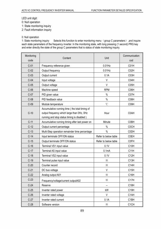
AC70 VC CONTROL FREQUENCY INVERTER MANUAL FUNCTION PARAMETER DETAILED SPECIFICATION
89
LED unit digit: 0: Null operation 1: State monitoring inquiry 2: Fault information inquiry 0: Null operation 1: State monitoring inquiry Selects this function to enter monitoring menu(group C parameters),and inquire each state parameters of the frequency inverter. In the monitoring state, with long pressing (1 second) PRG key and enter directly the state of the group C parameters that is status of state monitoring inquiry.
Monitoring
code Content Unit
Communication
cod
C-01 Frequency reference given 0.01Hz C01H
C-02 Output frequency 0.01Hz C02H
C-03 Output current 0.1A C03H
C-04 Input voltage V C04H
C-05 Output voltage V C05H
C-06 Machine speed RPM C06H
C-07 PID given value % C07H
C-08 PID feedback value % C08H
C-09 Module temperature C09H
C-10
Accumulative running time ( the total timing of
output frequency which large than 0Hz, 0Hz
running and stop status timing is disabled ) Hour C0AH
C-11 Accumulative running timing after last power on Minute C0BH
C-12 Output current percentage % C0CH
C-13 Multi-Step operation remainder time percentage % C0DH
C-14 Input terminals OFF/ON status Refer to below table C0EH
C-15 Output terminals OFF/ON status Refer to below table C0FH
C-16 Terminal VS1 input value 0.1V C10H
C-17 Terminal AS input value 0.1mA C11H
C-18 Terminal VS2 input value 0.1V C12H
C-19 Terminal pulse input value ※ C13H
C-20 Counter record ※ C14H
C-21 DC bus voltage V C15H
C-22 Analog output A01 ※ C16H
C-23 Frequency/voltage/current outputA02 ※ C17H
C-24 Reserve -- C18H
C-25 Inverter rated power kW C19H
C-26 Inverter rated voltage V C1AH
C-27 Inverter rated current 0.1A C1BH
C-28 Software version ※ C1CH

AC70 VC CONTROL FREQUENCY INVERTER MANUAL FUNCTION PARAMETER DETAILED SPECIFICATION
90
Input terminal OFF/ON state schematic diagram
Output terminal OFF/ON status schematic diagram
2: Fault information inquiry After inquiry setting, digital LED display below table information. Recycling shows is available via press up and down keys.
Serial number
Definition Remark Communication
code
Er.01 The latest fault information Refer to fault information code to get more in detail
E01H
Er.02 The cumulative running time before the latest fault
Units: hour E02H
Er.03 Output frequency while the latest fault Units: Hz E03H
Er.04 DC bus voltage while the latest fault Units: V E04H
Er.05 Output current while the latest fault Units: A E05H
Er.06 Output voltage while the latest fault Units: V E06H
Er.07 Module temperature while the latest fault Units: E07H

AC70 VC CONTROL FREQUENCY INVERTER MANUAL FUNCTION PARAMETER DETAILED SPECIFICATION
91
Er.08 Running direction while the latest fault 0.Forward 1.reverse E08H
Er.09 Running status while the latest fault 0. Stop 1. Constant running 2. Acceleration 3. Deceleration
E09H
Er.10 Protection status while the latest fault 0. Normal 1. Only voltage amplitude limit 2. Only current amplitude limit 3. Both voltage and current amplitude limit
E0AH
Er.11 Input terminal status while the latest fault See above table E0BH
Er.12 Output terminal status while the latest fault See above table E0CH
Er.13 The latest first fault information E0DH
Er.14 The latest second fault information E0EH
Er.15 The latest third fault Information E0FH
Fault information code table: Serial
number Keyboard display content Fault information
0 ---- No fault
1 L.U.1 The power supply is too low in stop (Don’t record this fault in fault logging)
2 L.U.2 The power supply is too low in running (Don’t record this fault in fault logging)
3 o.U.1 Overvoltage in acceleration
4 o.U.2 Overvoltage in deceleration
5 o.U.3 Overvoltage in constant speed
6 o.U.4 Over voltage in stop
7 o.C.1 Over current in acceleration
8 o.C.2 Over current in deceleration
9 o.C.3 Over current Constant speed
10 o.L.1 Motor overload
11 o.L.2 Inverter overload
12 Sc System fault
13 o.H. Inverter interior overheat
14 Sen Feedback sensor fault (Don’t record this fault in fault logging)
15 Err1 Phase missing in input side
16 Err2 Phase missing in output side
17 Err3 Current detected fault (Don’t record this fault in fault logging)
18 Err4 Inverter external fault
19 Err5 Swing frequency running parameter setting error
20 Err6 Keypad communication fault (Don’t record this fault in fault logging)
21 LIFE Reserved (Seek to the technical support, don’t record this fault in fault logging)
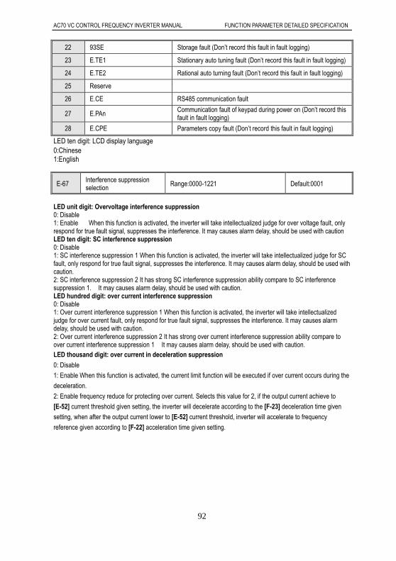
AC70 VC CONTROL FREQUENCY INVERTER MANUAL FUNCTION PARAMETER DETAILED SPECIFICATION
92
22 93SE Storage fault (Don’t record this fault in fault logging)
23 E.TE1 Stationary auto tuning fault (Don’t record this fault in fault logging)
24 E.TE2 Rational auto turning fault (Don’t record this fault in fault logging)
25 Reserve
26 E.CE RS485 communication fault
27 E.PAn Communication fault of keypad during power on (Don’t record this fault in fault logging)
28 E.CPE Parameters copy fault (Don’t record this fault in fault logging)
LED ten digit: LCD display language 0:Chinese 1:English
E-67 Interference suppression selection
Range:0000-1221 Default:0001
LED unit digit: Overvoltage interference suppression 0: Disable 1: Enable When this function is activated, the inverter will take intellectualized judge for over voltage fault, only respond for true fault signal, suppresses the interference. It may causes alarm delay, should be used with caution LED ten digit: SC interference suppression 0: Disable 1: SC interference suppression 1 When this function is activated, the inverter will take intellectualized judge for SC fault, only respond for true fault signal, suppresses the interference. It may causes alarm delay, should be used with caution. 2: SC interference suppression 2 It has strong SC interference suppression ability compare to SC interference suppression 1. It may causes alarm delay, should be used with caution. LED hundred digit: over current interference suppression 0: Disable 1: Over current interference suppression 1 When this function is activated, the inverter will take intellectualized judge for over current fault, only respond for true fault signal, suppresses the interference. It may causes alarm delay, should be used with caution. 2: Over current interference suppression 2 It has strong over current interference suppression ability compare to over current interference suppression 1 It may causes alarm delay, should be used with caution. LED thousand digit: over current in deceleration suppression
0: Disable
1: Enable When this function is activated, the current limit function will be executed if over current occurs during the
deceleration.
2: Enable frequency reduce for protecting over current. Selects this value for 2, if the output current achieve to
[E-52] current threshold given setting, the inverter will decelerate according to the [F-23] deceleration time given
setting, when after the output current lower to [E-52] current threshold, inverter will accelerate to frequency
reference given according to [F-22] acceleration time given setting.
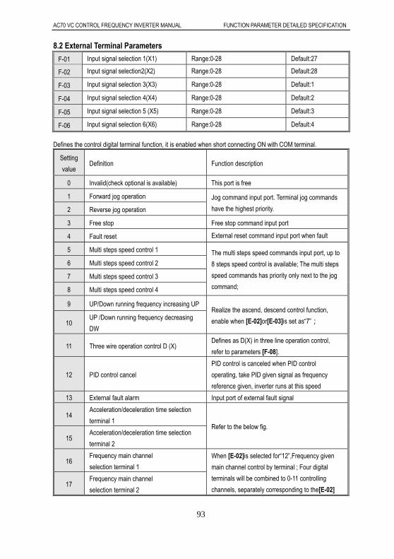
AC70 VC CONTROL FREQUENCY INVERTER MANUAL FUNCTION PARAMETER DETAILED SPECIFICATION
93
8.2 External Terminal Parameters
F-01 Input signal selection 1(X1) Range:0-28 Default:27
F-02 Input signal selection2(X2) Range:0-28 Default:28
F-03 Input signal selection 3(X3) Range:0-28 Default:1
F-04 Input signal selection 4(X4) Range:0-28 Default:2
F-05 Input signal selection 5 (X5) Range:0-28 Default:3
F-06 Input signal selection 6(X6) Range:0-28 Default:4
Defines the control digital terminal function, it is enabled when short connecting ON with COM terminal.
Setting
value Definition Function description
0 Invalid(check optional is available) This port is free
1 Forward jog operation Jog command input port. Terminal jog commands
have the highest priority. 2 Reverse jog operation
3 Free stop Free stop command input port
4 Fault reset External reset command input port when fault
5 Multi steps speed control 1 The multi steps speed commands input port, up to
8 steps speed control is available; The multi steps
speed commands has priority only next to the jog
command;
6 Multi steps speed control 2
7 Multi steps speed control 3
8 Multi steps speed control 4
9 UP/Down running frequency increasing UP Realize the ascend, descend control function,
enable when [E-02]or[E-03]is set as“7”; 10 UP /Down running frequency decreasing
DW
11 Three wire operation control D (X) Defines as D(X) in three line operation control,
refer to parameters [F-08].
12 PID control cancel
PID control is canceled when PID control
operating, take PID given signal as frequency
reference given, inverter runs at this speed
13 External fault alarm Input port of external fault signal
14 Acceleration/deceleration time selection
terminal 1 Refer to the below fig.
15 Acceleration/deceleration time selection
terminal 2
16 Frequency main channel
selection terminal 1
When [E-02]is selected for“12”,Frequency given
main channel control by terminal ; Four digital
terminals will be combined to 0-11 controlling
channels, separately corresponding to the[E-02] 17
Frequency main channel
selection terminal 2
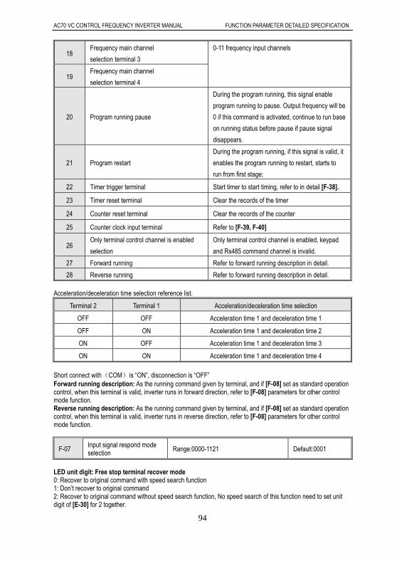
AC70 VC CONTROL FREQUENCY INVERTER MANUAL FUNCTION PARAMETER DETAILED SPECIFICATION
94
18 Frequency main channel
selection terminal 3
0-11 frequency input channels
19 Frequency main channel
selection terminal 4
20 Program running pause
During the program running, this signal enable
program running to pause. Output frequency will be
0 if this command is activated, continue to run base
on running status before pause if pause signal
disappears.
21 Program restart
During the program running, if this signal is valid, it
enables the program running to restart, starts to
run from first stage;
22 Timer trigger terminal Start timer to start timing, refer to in detail [F-38].
23 Timer reset terminal Clear the records of the timer
24 Counter reset terminal Clear the records of the counter
25 Counter clock input terminal Refer to [F-39, F-40]
26 Only terminal control channel is enabled
selection
Only terminal control channel is enabled, keypad
and Rs485 command channel is invalid.
27 Forward running Refer to forward running description in detail.
28 Reverse running Refer to forward running description in detail.
Acceleration/deceleration time selection reference list.
Terminal 2 Terminal 1 Acceleration/deceleration time selection
OFF OFF Acceleration time 1 and deceleration time 1
OFF ON Acceleration time 1 and deceleration time 2
ON OFF Acceleration time 1 and deceleration time 3
ON ON Acceleration time 1 and deceleration time 4
Short connect with(COM)is “ON”, disconnection is “OFF” Forward running description: As the running command given by terminal, and if [F-08] set as standard operation control, when this terminal is valid, inverter runs in forward direction, refer to [F-08] parameters for other control mode function. Reverse running description: As the running command given by terminal, and if [F-08] set as standard operation control, when this terminal is valid, inverter runs in reverse direction, refer to [F-08] parameters for other control mode function.
F-07 Input signal respond mode selection Range:0000-1121 Default:0001
LED unit digit: Free stop terminal recover mode 0: Recover to original command with speed search function 1: Don’t recover to original command 2: Recover to original command without speed search function, No speed search of this function need to set unit digit of [E-30] for 2 together.

AC70 VC CONTROL FREQUENCY INVERTER MANUAL FUNCTION PARAMETER DETAILED SPECIFICATION
95
LED ten digit: UP and DW terminal control starting frequency setting 0: Runs with UP/DW terminal adjusting without save the frequency record after power loss. 1: UP/DW terminal adjusting, save the frequency record after power off stop. Inverter will run to last stop moment frequency and then perform UP/DW adjusting. (Refer to [F-70] to Check or modify last stop moment frequency). 2. Runs to preset frequency [F-70] first, and then execute UP/DW adjusting. LED hundred digit: STOP/RESE of keypad effective range selection. 0: STOP/RESE key valid only when under keypad control 1: STOP/RESE key valid under any run command source. This function is suitable for using emergency stop in NOT keypad control mode. Note: If selects to STOP/RESE key valid under any run command source, pressing the stop key of keypad, inverter will be located in stop lock status when in terminal control or RS485 control mode. If want to using terminal or Rs485 running control channel command to restart inverter running, you must sent stop command by given channel to unlock stop status first. Frequency inverter enable to restart after stop status unlocking. LED thousand digit: Terminal running mode selection after fault reset 0: Start inverter running directly after power on in terminal control mode 1: Stop first and then start in terminal control mode Note: When fault occurs of inverter, reset valid signal can be sent by the all 3 running control command. If the frequency inverter adopts the terminal control mode, after frequency inverter reset by receiving terminal or the other two channels’ reset signal, this parameter can be used to select whether to carry on the terminal running command.
F-08 Terminal running control mode Range:0000-0005 Default: 0000
LED unit digit: Terminal control mode selection 0: Standard running control mode Running and direction are bonded together. This 2 wire control mode is most commonly using. Uses X1 (forward running) and X2 (reverse running) terminals command to determine the Forward /Reverse running of motor. Refer to below fig.
1: Two wire running control mode Running and direction are separated. Uses the forward running terminal X1 (forward running) to determine running control, reverse running terminal X2 (reverse running) to determine direction control. Refer to below fig.
2. Three wire control mode 1 Three wire control terminal (Xi) is used for stop running terminal. Running command determined by forward running terminal X1 (forward running), direction determined by reverse running terminal X2 ( reverse running). 3 wire running control terminal Xi is used for enable input.

AC70 VC CONTROL FREQUENCY INVERTER MANUAL FUNCTION PARAMETER DETAILED SPECIFICATION
96
Tip: In 3 wire control mode 1 Fig, SB1 is a normal close stop button, SB2 is a normal open button. K1 is a direction selection switch; Xi is multi-function terminal (X1-X6) which have been programmed for 3 wire running control terminal. 3: 3 wire control mode 2 In this mode, 3 wire running control terminal (Xi) is used for stop running terminal, the running command is generated by forward running terminal X1(forward running) or reverse running terminal X2( reverse running ), also control the direction at the same time.
Tip: In 3 wire control mode 2 Fig, SB1 is a normal close button, SB2 and SB3 both are normal open button and pulse edge is valid, uses for inverter direction control. 4: 3 wire control mode 3 3wire running control terminal (X1) is used for running command given terminal, running in connecting ON, stop in disconnecting OFF. Rotation direction is determined by forward running terminal X1 ( forward running) or reverse running terminal X2( reverse running). Every staring running with last time direction memorized
Tip: 1. SB2 and SB3 both are normal open button, and enable by pulse edge.
2. If need start motor in forward direction, press the K1 first, and press SB2 immediately.

AC70 VC CONTROL FREQUENCY INVERTER MANUAL FUNCTION PARAMETER DETAILED SPECIFICATION
97
3. If need start motor in reverse direction, press the K1 first, and press SB3 immediately. 5: 3 wire control mode 4 3 wire running control terminal (X1) uses for stop command terminal, running command is determined by forward running terminal X1 (forward running), direction is controlled by reverse running terminal X2( reverse running), and direction will be change after every Xi is activated. Every starts running based on last direction memorized. 3 wire running control terminal X1 for effective input.
Tip: SB1 is a normal stop button, SB2 is a normal open button. K1 used for running direction selection button. Xi is multi-function terminal (X1-X6) which have been programmed for 3 wire running control terminal. LED ten digit: Reserve LED hundred digit: Reserve LED thousand: Reserve
F-09 1 step speed setting 1X Rang:0.00Hz-upper limit frequency Default: 30.00Hz
F-10 2 step speed setting 2X Rang:0.00Hz-upper limit frequency Default:25.00Hz
F-11 3 step speed setting 3X Rang:0.00Hz-upper limit frequency Default: 40.00Hz
F-12 4 step speed setting 4X Rang:0.00Hz-upper limit frequency Default: 50.00Hz
F-13 5 step speed setting 5X Rang:0.00Hz-upper limit frequency Default: 50.00Hz
F-14 6 step speed setting 6X Rang:0.00Hz-upper limit frequency Default: 40.00Hz
F-15 7 step speed setting 7X Rang:0.00Hz-upper limit frequency Default: 25.00Hz
F-16 8 step speed setting 8X Rang:0.00Hz-upper limit frequency Default: 10.00Hz
Uses for setting program running and multi-step speed running frequency separately. Multi-step speed control has the priority only next to the jog function. If users choose the multi-step speed running mode, they need to set four multi-function input terminals as multi-step control terminal. ON/OFF between the four terminals and (COM) determine the running speed steps. Its running and direction is controlled by the running signal and direction given by the running control command channel [E-01]. And its acceleration, deceleration time is controlled by the acceleration, deceleration time 1 in default. Or specifies the particular acceleration, deceleration time by [F-01]-[F-06] parameters setting. Swing frequency control need to configure the [F-09] and [F-10], refer to [H-51]parameters for the requirement setting of [F-09] and [F-10]. Inverter will appear fault alarm “Err5” if wrong setting. Tip 1. Multiple step speed running don’t limited by lower limit frequency, but subject to upper limit frequency. 2. Output of program running is subject to limit by upper and lower limit frequency. Inverter will run with lower limit frequency when the frequency given less than lower limit frequency.

AC70 VC CONTROL FREQUENCY INVERTER MANUAL FUNCTION PARAMETER DETAILED SPECIFICATION
98
Short connecting with COM stands for ON, disconnecting for OFF
Multi-step control
terminal 4
Multi-step control
terminal 3
Multi-step control
terminal 2
Multi-step control
terminal 1
Terminal
Step
Speed
OFF OFF OFF ON 1X
OFF OFF ON OFF 2X
OFF OFF ON ON 3X
OFF ON OFF OFF 4X
OFF ON OFF ON 5X
OFF ON ON OFF 6X
OFF ON ON ON 7X
ON OFF OFF OFF 8X
F-17-F-18 Reverse
F-19 Speed search tracking speed Range:0.1-10.0% Default: 0.2%
F-20 Voltage stores time Range:0.10-10.00s Default: 0.60s
F-21 Speed search respond current threshold value Range:10-200% Default: 120%
This group parameters will be use in software speed search mode. Software speed search will detect out the motor speed from current, and stores voltage based on [F-20] voltage stores time under upper limit frequency or given frequency. When the output current bigger than [F-21], inverter will lower the output frequency with [F-19] speed search speed tracking. When the current lower than [F-21] and maintain [E-62] time setting, it judges the output frequency and motor speed is synchronous, will accelerate or decelerate to frequency reference given. Software speed search processing schematic as following tale:
Note: The motor may decelerate suddenly when drive a light load.
F-22 Frequency reducing acceleration time Range:0.1-6500.0s Default: 2.0s
F-23 Frequency reducing deceleration time Range:0.1-6500.0s Default: 0.3s
Frequency reducing accel/decel. time: When parameters[E-67] is set to “2****”, inverter will reduce frequency
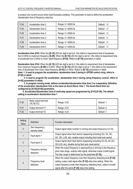
AC70 VC CONTROL FREQUENCY INVERTER MANUAL FUNCTION PARAMETER DETAILED SPECIFICATION
99
to protect over current occurs when load fluctuates suddenly. This parameter is used to define the acceleration /deceleration time of frequency reducing.
F-24 Acceleration time 2 Range: 0.1-6500.0s Default: ※
F-25 Deceleration time 2 Range: 0.1-6500.0s Default: ※
F-26 Acceleration time 3 Range: 0.1-6500.0s Default: ※
F-27 Deceleration time 3 Range: 0.1-6500.0s Default: ※
F-28 Acceleration time 4 Range: 0.1-6500.0s Default: ※
F-29 Deceleration time 4 Range: 0.1-6500.0s Default: ※
Acceleration time 2/3/4: When the [E-15] LED ten digit is set to 0, this refers to requirement time of accelerate from 0.00Hz to maximum frequency [E-09]. When the [E-15] LED ten digit is set to1, this refers to requirement time of accelerate from 0.00Hz to motor rated frequency [H-53]. Refers to [E-15] parameters in detail. Deceleration time 2/3/4: When the [E-15] LED ten digit is set to 0, this refers to requirement time of decelerates from maximum frequency [E-09] to 0.00Hz. When the [E-15] LED ten digit is set to 1, this refers to the requirement time of decelerates from motor rated frequency [H-53] to 0.00Hz. Refers to [E-15] parameters in detail. Note: 1. It need to program the acceleration, deceleration time 2 during in UP/DW control ruing, refers to [E-02] in detail. 2. It need to program the acceleration, deceleration time 2 during swing frequency control, refers to [H-65] parameters in detail. 3. In program running mode, defines acceleration/deceleration time from 2 to 4 separately. Definition of the acceleration /deceleration time is the same as Accel./Decel. time 1. The Accel./Decel time are configured by [H-35]-[H-49] parameters.
4. Acceleration/deceleration time of multi-step speed are programmed by [F-01]-[F-06]. The default setting is acceleration/ deceleration time 1.
F-30 Relay output terminal (TA,TB,TC) Range: 0-22 Default: 1
F-31 Output terminal Y1 Range: 0-22 Default: 4
F-32 Output terminal Y2 Range: 0-22 Default: 7
Setting Value
Definition Function description
0 Zero frequency ( standby state)
Output signal when inverter is running and output frequency is 0 Hz,
1 Fault alarm 1 Output signal when fault alarms happening (including OU, OL, SC, OC, OH, LUS, etc), enable output including fault reset auto period
2 Fault alarm 2 Output signal when fault alarms happening (including OU,OL,SC,OC, OH,LUS, etc), disable during fault auto reset period.
3 Frequency arriving detection
When the output frequency is approaching or arriving to the frequency given bias range, outputs valid signal, otherwise output invalid signal. The bias range is determined by the parameter [F-33].
4 Frequency level detection
When the output frequency over than frequency detecting level [F-34] setting, output valid signal after [F-35] relay time setting. When the output frequency lower than frequency detecting level, output a invalid signal after the same [F-35] relay time setting.

AC70 VC CONTROL FREQUENCY INVERTER MANUAL FUNCTION PARAMETER DETAILED SPECIFICATION
100
5 running statues Output signal when inverter in running status.
6 Reverse running Output signal when inverter runs in reverse direction
7 Under voltage of inverter
Output signalwhen inverter shows “LU1/2” alarms due to under voltage
8 Overload pre-alarm Outputs signal, when the output current of frequency inverter reach to [F-36] and [F-37] setting values, it outputs signal.
9 Output frequency reach upper limit frequency
Outputs signal, when the output frequency reach to upper limit frequency.
10 Output frequency reach lower limit frequency
Outputs signal, when the output frequency reach to lower limit frequency.
11 External fault stop Outputs valid signal when inverter stop resulted in by external fault alarm signal input.
12 Timer times up When it is time up to the given setting time of timer of inverter’s inside. Outputs a 1 second width valid pulse signal.
13 Counter reach maximum values
When counter reach to maximum value, output terminal outputs a valid signal with width equal to external clock period.
14 Counter reach setting values
When the counter reach the setting values, output terminal outputs valid signal, and continue to count until achieve to maximum value. This valid signal will cancel when counter reset which cause by counted up to maximum value.
15 PID feedback upper limit alarm
Outputs signal when detecting PID feedback value reach to upper limit alarm value [H-26].
16 PID feedback lower limit alarm
Outputs signal when detecting PID feedback value reach to lower limit alarm value [H-27].
17 Sensor broken When the feedback less then [H-28] setting value, the sensor is considered to broken during the detecting signal in PID control. It will output signal.
18 Program running cycle completed
When program finishes the cycle running, it output 500ms low level signal.
19 Program running step completed
When program finishes the step running, it outputs 500ms low level signal.
20 Dynamic braking processing
Outputs signal when perform dynamic braking.
21 Output terminal control by external
When selects this function, output terminal status can be changed by [H-79] setting. [H-79] value configured by RS485 communication, the binary 0,1, 2 are corresponding to relay output terminal, Y1, and Y2 terminal.
22
22. Fault alarm 1. (Including fault auto reset period, including fault-LU1 )
Output signal when fault alarms happening (including OU, OL, SC, OC, OH, LUS, etc), enable output including fault reset auto period
Tip: The output terminal of relay TA-TC close, TB-TC open are considered to valid signal, low level output
terminal Y1, Y2 combine with (+24) terminal output 24V power supply considered valid signal.
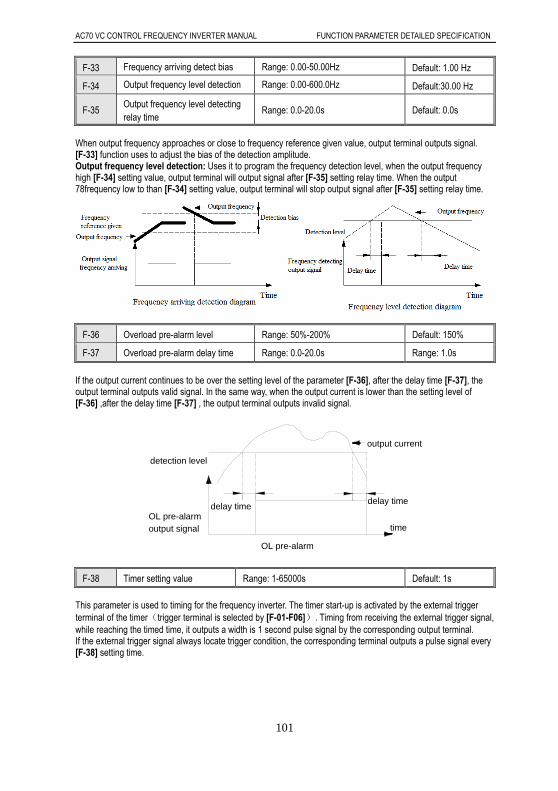
AC70 VC CONTROL FREQUENCY INVERTER MANUAL FUNCTION PARAMETER DETAILED SPECIFICATION
101
F-33 Frequency arriving detect bias Range: 0.00-50.00Hz Default: 1.00 Hz
F-34 Output frequency level detection Range: 0.00-600.0Hz Default:30.00 Hz
F-35 Output frequency level detecting relay time
Range: 0.0-20.0s Default: 0.0s
When output frequency approaches or close to frequency reference given value, output terminal outputs signal. [F-33] function uses to adjust the bias of the detection amplitude. Output frequency level detection: Uses it to program the frequency detection level, when the output frequency high [F-34] setting value, output terminal will output signal after [F-35] setting relay time. When the output 78frequency low to than [F-34] setting value, output terminal will stop output signal after [F-35] setting relay time.
F-36 Overload pre-alarm level Range: 50%-200% Default: 150%
F-37 Overload pre-alarm delay time Range: 0.0-20.0s Range: 1.0s
If the output current continues to be over the setting level of the parameter [F-36], after the delay time [F-37], the output terminal outputs valid signal. In the same way, when the output current is lower than the setting level of [F-36] ,after the delay time [F-37] , the output terminal outputs invalid signal.
delay timedelay time
time
detection level
output current
OL pre-alarm output signal
OL pre-alarm
F-38 Timer setting value Range: 1-65000s Default: 1s
This parameter is used to timing for the frequency inverter. The timer start-up is activated by the external trigger terminal of the timer(trigger terminal is selected by [F-01-F06]). Timing from receiving the external trigger signal, while reaching the timed time, it outputs a width is 1 second pulse signal by the corresponding output terminal. If the external trigger signal always locate trigger condition, the corresponding terminal outputs a pulse signal every [F-38] setting time.

AC70 VC CONTROL FREQUENCY INVERTER MANUAL FUNCTION PARAMETER DETAILED SPECIFICATION
102
F-39 Counter maximum value Range: 1-65000 Default: 1000
F-40 Counter setting value Range: 1-counter maximum value Default: 100
This parameter stipulate the counting action of the interior counter, clock terminal of the counter is selected by the parameter [F-01-F-06]. When the count value to the exterior clock reaches [F-39] setting value, in the corresponding output terminal, it outputs a valid signal with a width equal to exterior clock cycle. The output signal stops while the next count signal is input. When the count value to the exterior clock reaches [F-40] setting value, in the corresponding output terminal, it outputs a valid signal. While it reached [F-39] and the counter clear to zero, this output valid signal abolishes. The clock cycle is required to be greater than 10 ms; And the minimum pulse width is 5ms.
counter arrive setting counter arrive maximum
counter arrive max output
counter arrive max output
output terminal
output terminal
F-41 VS1 terminal input voltage lower limit
Range: 0.00V-[F-42] Default: 0.50V
F-42 VS1 terminal input voltage upper limit
Range:[F-41]-10.00V Default: 9.50V
F-43 VS1 terminal input voltage gain
Range: 0.01-5.00 Default: 1.00
VS1 terminal input voltage lower limit This function defines the minimum signal of the analog input terminal(VS1)receiving. Frequency inverter will automatically filter the voltage signal whose value is lower than this value. VS1 terminal input voltage upper limit This function defines the maximum signal of the analog input terminal(VS1)receiving. Frequency inverter will automatically filter the voltage signal whose value is higher than this value. VS1 terminal input voltage gain This function is used to amplify or reduce the (VS1) terminal input analog value.
F-44 VS2 terminal input voltage lower limit Range: -10.00V-[F-45] Default: 0.50V
F-45 VS2 terminal input voltage upper limit
Range: [F-44]-10.00V Default:9.50V
F-46 VS2 terminal input voltage gain
Range: 0.01-5.00 Default:1.00
F-47 VS2 terminal input zero offset
Range: -1.00V-1.00V Default:0.00V
F-48 VS2 terminal input bipolar adjust and direction control
Range: 0,1,2 Default: 0
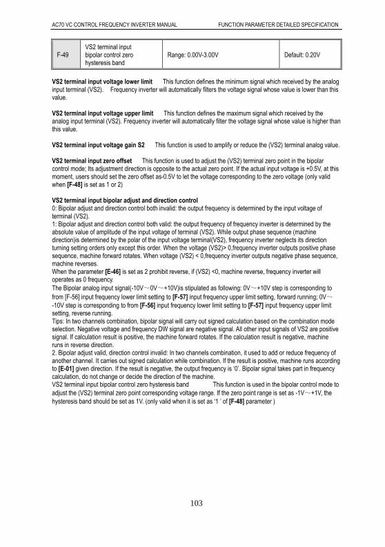
AC70 VC CONTROL FREQUENCY INVERTER MANUAL FUNCTION PARAMETER DETAILED SPECIFICATION
103
F-49 VS2 terminal input bipolar control zero hysteresis band
Range: 0.00V-3.00V Default: 0.20V
VS2 terminal input voltage lower limit This function defines the minimum signal which received by the analog input terminal (VS2). Frequency inverter will automatically filters the voltage signal whose value is lower than this value. VS2 terminal input voltage upper limit This function defines the maximum signal which received by the analog input terminal (VS2). Frequency inverter will automatically filter the voltage signal whose value is higher than this value. VS2 terminal input voltage gain S2 This function is used to amplify or reduce the (VS2) terminal analog value. VS2 terminal input zero offset This function is used to adjust the (VS2) terminal zero point in the bipolar control mode; Its adjustment direction is opposite to the actual zero point. If the actual input voltage is +0.5V, at this moment, users should set the zero offset as-0.5V to let the voltage corresponding to the zero voltage (only valid when [F-48] is set as 1 or 2) VS2 terminal input bipolar adjust and direction control 0: Bipolar adjust and direction control both invalid: the output frequency is determined by the input voltage of terminal (VS2). 1: Bipolar adjust and direction control both valid: the output frequency of frequency inverter is determined by the absolute value of amplitude of the input voltage of terminal (VS2). While output phase sequence (machine direction)is determined by the polar of the input voltage terminal(VS2), frequency inverter neglects its direction turning setting orders only except this order. When the voltage (VS2)> 0,frequency inverter outputs positive phase sequence, machine forward rotates. When voltage (VS2) < 0,frequency inverter outputs negative phase sequence, machine reverses. When the parameter [E-46] is set as 2 prohibit reverse, if (VS2) <0, machine reverse, frequency inverter will operates as 0 frequency. The Bipolar analog input signal(-10V~0V~+10V)is stipulated as following: 0V~+10V step is corresponding to from [F-56] input frequency lower limit setting to [F-57] input frequency upper limit setting, forward running; 0V~ -10V step is corresponding to from [F-56] input frequency lower limit setting to [F-57] input frequency upper limit setting, reverse running. Tips: In two channels combination, bipolar signal will carry out signed calculation based on the combination mode selection. Negative voltage and frequency DW signal are negative signal. All other input signals of VS2 are positive signal. If calculation result is positive, the machine forward rotates. If the calculation result is negative, machine runs in reverse direction. 2. Bipolar adjust valid, direction control invalid: In two channels combination, it used to add or reduce frequency of another channel. It carries out signed calculation while combination. If the result is positive, machine runs according to [E-01] given direction. If the result is negative, the output frequency is ‘0’. Bipolar signal takes part in frequency calculation, do not change or decide the direction of the machine. VS2 terminal input bipolar control zero hysteresis band This function is used in the bipolar control mode to adjust the (VS2) terminal zero point corresponding voltage range. If the zero point range is set as -1V~+1V, the hysteresis band should be set as 1V. (only valid when it is set as ‘1 ’ of [F-48] parameter )

AC70 VC CONTROL FREQUENCY INVERTER MANUAL FUNCTION PARAMETER DETAILED SPECIFICATION
104
VS2 unipolar control diagram
input voltage
lower limit VS2 input analog
input voltage
lower limit
F-57 corresponding frequency
F-56 corresponding
frequency
frequency
VS2 bipolar control diagram
F-57 correspondingfrequency
Upper limitinput voltage
VS2 input analog F-56 corresponding frequency
zero point F-56 corresponding frequency
input voltageLower limit
F-57 correspondingfrequencyFrequency
Tip: When (VS2) is used as PID given or feedback channel, the function of bipolar is invalid. At this moment, the usage of (VS2) terminal is the same with the (VS1) terminal. Namely, when (VS2) <0, frequency inverter think the input of this port is 0.
F-50 AS terminal input current lower limit
Range: 0.00mA-[F-51] Default: 4.20mA
F-51 AS terminal input current upper limit
Range:[F-50]-20.00mA Default: 19.50mA
F-52 AS terminal input current gain
Range: 0.01-5.00 Default: 1.00
AS terminal input current lower limit This function defines the minimum signal which received by the analog input terminal(AS),frequency inverter will automatically filters the current signal whose value is lower than this value; For example, if the factory setting of this value ‘4.00’,4.00-20.00mA input current is available. AS terminal input current upper limit This function defines the maximum signal which received by the analog input terminal (AS), frequency inverter will automatically filters the current signal whose value is higher than this value. AS terminal input current gain This function is used to amplify or reduce the (AS) terminal.
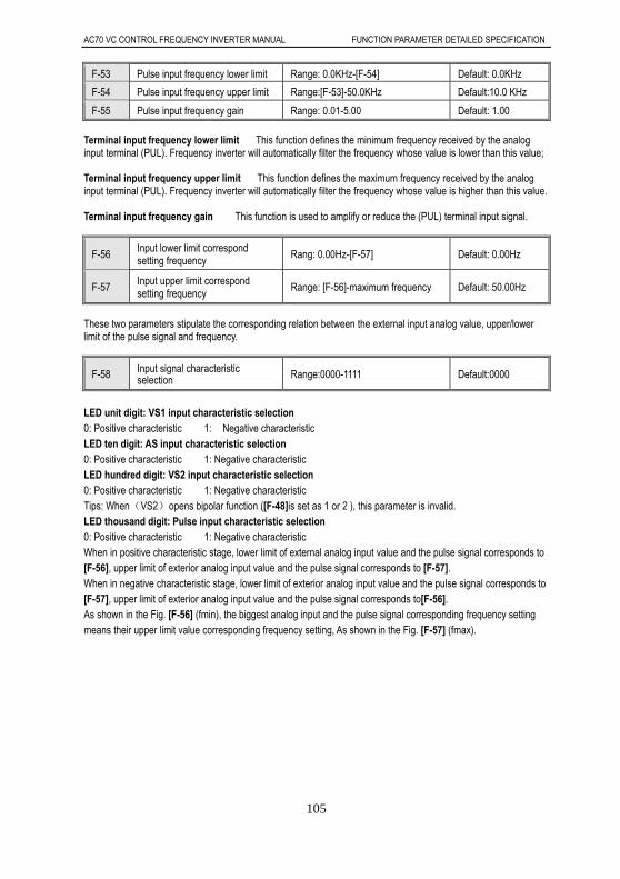
AC70 VC CONTROL FREQUENCY INVERTER MANUAL FUNCTION PARAMETER DETAILED SPECIFICATION
105
F-53 Pulse input frequency lower limit Range: 0.0KHz-[F-54] Default: 0.0KHz
F-54 Pulse input frequency upper limit Range:[F-53]-50.0KHz Default:10.0 KHz
F-55 Pulse input frequency gain Range: 0.01-5.00 Default: 1.00
Terminal input frequency lower limit This function defines the minimum frequency received by the analog input terminal (PUL). Frequency inverter will automatically filter the frequency whose value is lower than this value; Terminal input frequency upper limit This function defines the maximum frequency received by the analog input terminal (PUL). Frequency inverter will automatically filter the frequency whose value is higher than this value. Terminal input frequency gain This function is used to amplify or reduce the (PUL) terminal input signal.
F-56 Input lower limit correspond setting frequency
Rang: 0.00Hz-[F-57] Default: 0.00Hz
F-57 Input upper limit correspond setting frequency
Range: [F-56]-maximum frequency Default: 50.00Hz
These two parameters stipulate the corresponding relation between the external input analog value, upper/lower limit of the pulse signal and frequency.
F-58 Input signal characteristic selection Range:0000-1111 Default:0000
LED unit digit: VS1 input characteristic selection 0: Positive characteristic 1: Negative characteristic LED ten digit: AS input characteristic selection 0: Positive characteristic 1: Negative characteristic LED hundred digit: VS2 input characteristic selection 0: Positive characteristic 1: Negative characteristic Tips: When(VS2)opens bipolar function ([F-48]is set as 1 or 2 ), this parameter is invalid. LED thousand digit: Pulse input characteristic selection 0: Positive characteristic 1: Negative characteristic When in positive characteristic stage, lower limit of external analog input value and the pulse signal corresponds to [F-56], upper limit of exterior analog input value and the pulse signal corresponds to [F-57]. When in negative characteristic stage, lower limit of exterior analog input value and the pulse signal corresponds to [F-57], upper limit of exterior analog input value and the pulse signal corresponds to[F-56]. As shown in the Fig. [F-56] (fmin), the biggest analog input and the pulse signal corresponding frequency setting means their upper limit value corresponding frequency setting, As shown in the Fig. [F-57] (fmax).

AC70 VC CONTROL FREQUENCY INVERTER MANUAL FUNCTION PARAMETER DETAILED SPECIFICATION
106
input quantityfmax
fminfmin
fmax
input lowerlimit limil
frequency
input upper
Relationship between frequency setting and input quantity
frequency
input lowerlimit
input upperlimil
input quantity
F-59 Terminal analog input filtering time constant
Range: 0.01-5.00s Default: 0.50s
This is defined as the size of the input analog quantity signal filtering, for the purpose of eliminating the interference signal. The longer filtering time is, the stronger anti-interfere ability is, but the respond speed slow down; The shorter filter time is, the weaker anti-interfere ability is, but the respond speed become faster;
F-60 Output terminal(AO1)selection Range: 0-7 Default: 1
F-61 Output terminal(AO2)selection Range:0-7 Default: 3
Output signal (A01) and (A02) mode is programmed by [F-62] 0: Output signal disable 1: Output frequency/speed 2: Output current 3: Given frequency/speed reference 4: PID given value 5: PID feedback value 6: DC bus voltage 7: Output voltage
Tips: when (AO2)port is frequency pulse output or 4-20mA output, ‘0%’ corresponding output quantity is not zero.

AC70 VC CONTROL FREQUENCY INVERTER MANUAL FUNCTION PARAMETER DETAILED SPECIFICATION
107
F-62 Analog output signal selection Range: 0000-0023 Default: 0003
LED unit digit: A02 output signal mode selection 0: Frequency pulse train output default setting for 0.2KHz to 10.0KHz; 1:0-20mA 2:4-20mA 3:0-10V LED ten digit: A01 output signal mode selection 0:0-10V 1:0-20mA 2:4-20mA LED hundred digit: Reserve LED thousand digit: Reserve Tip: After output mode selected by software configured, it also need to select by J1, I2, J3, J4, J5 , terminals pin short connection. Refer to following for selecting in detail. A02 selects for frequency pulse train output, need select J1 among J1, J2, J3 dial switching. A02 selects for 0-20ma or 4-20mA output signal, need select J2 among J1, J2, J3 dial switching. A02 selects for 0-10V output signal, need select J2 among J1, J2, J3 dial switching. A01 selects for 0-20mA or 4-20mA output signal, need make J5 short connection, J4 disconnect. A01 selects for 0-10V output signal, need make J4 short connection, J5 disconnect. In the factory default setting of A01 and A02 output signal is 0-10V analog output. If need other output mode, please configure the software and hardware according requirement.
F-63 AO1 output signal gain Range: 25%-200% Default: 100%
F-64 AO2 output signal gain Range: 25%-200% Default: 100%
Used to adjust AO1 terminal output analog value and AO2 output signal value.
F-65 AO1 output signal zero adjust Range : -10%-10% Default: 0.0
F-66 AO2 output signal zero adjust Range : -10%-10% Default: 0.0
Used to adjust the output signal zero point of (AO1) terminal and (AO2) terminal. It is invalid to adjust this value when (AO2) is frequency pulse output.
F-67 Keypad potentiometer input lower limit voltage Range: 0.00V-[F-68] Default: 0.20V
F-68 Keypad potentiometer input upper limit voltage Range:[F-67]-5.50V Default: 4.80V
F-69 Keypad potentiometer gain Range: 0.00-5.00 Default: 1.00
Keypad potentiometer input voltage lower limit This function defines the minimum signal received by the keyboard potentiometer. Frequency inverter will automatically filters the signal whose value is lower than this value; Keypad potentiometer input voltage upper limit This function defines the maximum signal received by the keyboard potentiometer. Frequency inverter will automatically filters the signal whose value is upper than this value. Keypad potentiometer gain This function is used to amplify or reduce keyboard potentiometer input analog quantity. Tips: Keypad potentiometer input voltage upper limit is corresponding to frequency upper limit [E-10] , Keyboard potentiometer input voltage upper limit is corresponding to 0.00 Hz.
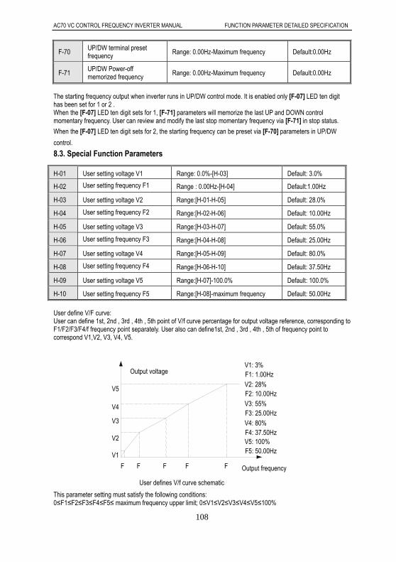
AC70 VC CONTROL FREQUENCY INVERTER MANUAL FUNCTION PARAMETER DETAILED SPECIFICATION
108
F-70 UP/DW terminal preset frequency Range: 0.00Hz-Maximum frequency Default:0.00Hz
F-71 UP/DW Power-off memorized frequency Range: 0.00Hz-Maximum frequency Default:0.00Hz
The starting frequency output when inverter runs in UP/DW control mode. It is enabled only [F-07] LED ten digit has been set for 1 or 2 . When the [F-07] LED ten digit sets for 1, [F-71] parameters will memorize the last UP and DOWN control momentary frequency. User can review and modify the last stop momentary frequency via [F-71] in stop status.
When the [F-07] LED ten digit sets for 2, the starting frequency can be preset via [F-70] parameters in UP/DW
control.
8.3. Special Function Parameters
User define V/F curve: User can define 1st, 2nd , 3rd , 4th , 5th point of V/f curve percentage for output voltage reference, corresponding to F1/F2/F3/F4/f frequency point separately. User also can define1st, 2nd , 3rd , 4th , 5th of frequency point to correspond V1,V2, V3, V4, V5.
This parameter setting must satisfy the following conditions: 0≤F1≤F2≤F3≤F4≤F5≤ maximum frequency upper limit; 0≤V1≤V2≤V3≤V4≤V5≤100%
H-01 User setting voltage V1 Range: 0.0%-[H-03] Default: 3.0%
H-02 User setting frequency F1 Range : 0.00Hz-[H-04] Default:1.00Hz
H-03 User setting voltage V2 Range:[H-01-H-05] Default: 28.0%
H-04 User setting frequency F2 Range:[H-02-H-06] Default: 10.00Hz
H-05 User setting voltage V3 Range:[H-03-H-07] Default: 55.0%
H-06 User setting frequency F3 Range:[H-04-H-08] Default: 25.00Hz
H-07 User setting voltage V4 Range:[H-05-H-09] Default: 80.0%
H-08 User setting frequency F4 Range:[H-06-H-10] Default: 37.50Hz
H-09 User setting voltage V5 Range:[H-07]-100.0% Default: 100.0%
H-10 User setting frequency F5 Range:[H-08]-maximum frequency Default: 50.00Hz
V5
V4
V3
F
V5: 100%F5: 50.00Hz
F2: 10.00Hz
Output voltage
Output frequency
User defines V/f curve schematic
V1: 3%
V2: 28%
V3: 55% F3: 25.00Hz V4: 80% F4: 37.50Hz
F1: 1.00Hz
F
V1
V2
F FF
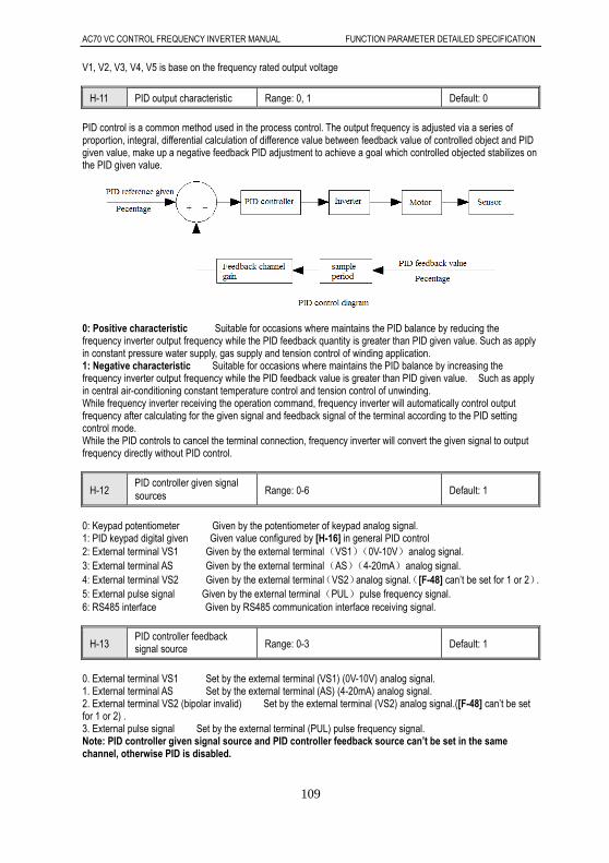
AC70 VC CONTROL FREQUENCY INVERTER MANUAL FUNCTION PARAMETER DETAILED SPECIFICATION
109
V1, V2, V3, V4, V5 is base on the frequency rated output voltage
H-11 PID output characteristic Range: 0, 1 Default: 0
PID control is a common method used in the process control. The output frequency is adjusted via a series of proportion, integral, differential calculation of difference value between feedback value of controlled object and PID given value, make up a negative feedback PID adjustment to achieve a goal which controlled objected stabilizes on the PID given value.
0: Positive characteristic Suitable for occasions where maintains the PID balance by reducing the frequency inverter output frequency while the PID feedback quantity is greater than PID given value. Such as apply in constant pressure water supply, gas supply and tension control of winding application. 1: Negative characteristic Suitable for occasions where maintains the PID balance by increasing the frequency inverter output frequency while the PID feedback value is greater than PID given value. Such as apply in central air-conditioning constant temperature control and tension control of unwinding. While frequency inverter receiving the operation command, frequency inverter will automatically control output frequency after calculating for the given signal and feedback signal of the terminal according to the PID setting control mode. While the PID controls to cancel the terminal connection, frequency inverter will convert the given signal to output frequency directly without PID control.
H-12 PID controller given signal sources Range: 0-6 Default: 1
0: Keypad potentiometer Given by the potentiometer of keypad analog signal. 1: PID keypad digital given Given value configured by [H-16] in general PID control 2: External terminal VS1 Given by the external terminal(VS1)(0V-10V)analog signal. 3: External terminal AS Given by the external terminal(AS)(4-20mA)analog signal. 4: External terminal VS2 Given by the external terminal(VS2)analog signal.([F-48] can’t be set for 1 or 2). 5: External pulse signal Given by the external terminal(PUL)pulse frequency signal. 6: RS485 interface Given by RS485 communication interface receiving signal.
H-13 PID controller feedback signal source Range: 0-3 Default: 1
0. External terminal VS1 Set by the external terminal (VS1) (0V-10V) analog signal. 1. External terminal AS Set by the external terminal (AS) (4-20mA) analog signal. 2. External terminal VS2 (bipolar invalid) Set by the external terminal (VS2) analog signal.([F-48] can’t be set for 1 or 2) . 3. External pulse signal Set by the external terminal (PUL) pulse frequency signal. Note: PID controller given signal source and PID controller feedback source can’t be set in the same channel, otherwise PID is disabled.

AC70 VC CONTROL FREQUENCY INVERTER MANUAL FUNCTION PARAMETER DETAILED SPECIFICATION
110
H-14 PID preset frequency Range: 0.00Hz-maximum frequency Default: 0.00Hz
H-15 PID preset frequency running time
Range: 0.1-6500.0s Default: 0.0s
This function make frequency inverter accelerate to PID preset frequency [H-14] with acceleration time 1 after PI operation starts, and will keep running for PID preset frequency running time [H-15] given, and then executes the PID close loop operation.
PID preset frequency running time diagram
preset frequency running time
Time
PID adjustment running
preset frequency
Frequency
H-16 PID keypad digital given Range: 0.0%-100.0% Default:50.0%
Only when [H-12] parameters is set for 1,this parameter is valid. Take the sensor maximum measuring range [H-18] as a benchmark. When this parameter is changed, PID given value of monitoring target will automatically synchronize change.
H-17 PID channel gain Range: 0.01-5.00 Default: 1.00
This function is used to amplify or reduce the input analog value of feedback channel
H-18 Sensor maximum measuring range
Range:1.0-100.0 Default:100.0
This function is used to adjust the display data of PID given value and PID feedback value. Actual LED display value= given (feedback) signal - lower input limit × sensor largest range
Upper input limit-lower input limit For example in pressure control, if it is set for sensor maximum pressure, the display value is actual pressure value. Assumes that take external terminal (VS1) for feedback single input channel, when VS1 upper limit voltage is 9V, the lower limit is 0.5V, the present feedback voltage is 4.5V, the maximum sensor measure range is 20mpa.
LED display value =(4.5-0.5)×20/(9-0.5)=9.4mpa
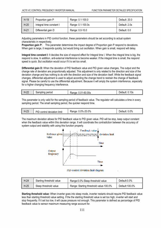
AC70 VC CONTROL FREQUENCY INVERTER MANUAL FUNCTION PARAMETER DETAILED SPECIFICATION
111
H-19 Proportion gain P Range: 0.1-100.0 Default: 20.0
H-20 Integral time constant I Range: 0.1-100.0s Default: 2.0s
H-21 Differential gain D Range: 0.0-10.0 Default: 0.0
Adjusting parameters in PID control function, these parameters should be set according to actual system characteristic in respectively. Proportion gain P: This parameter determines the impact degree of Proportion gain P respond to deviations. When gain is large, it responds quickly, but would bring out oscillation. When gain is small, respond will delay. Integral time constant I: It decides the size of respond effect for Integral time I. When the integral time is big, the respond is slow, In addition, anti-external interference is become weaker. If the integral time is small, the respond speed is quick. But oscillation would occur if it is set too small. Differential gain D: When the deviation of PID feedback value and PID given value changes, The output and the change rate of deviation are proportionally adjusted. This adjustment is only related to the direction and size of the deviation change and has nothing to do with the direction and size of the deviation itself. While the feedback signal changes, differential adjustment is used to adjust according the change trend to restrain the change of feedback signal. Please be careful to use the differential adjustment. Because it will amply the system interference, especially for a higher changing frequency interference.
H-22 Sampling period Range: 0.01-60.00s Default: 0.10s
This parameter is only valid for the sampling period of feedback value. The regulator will calculates a time in every sampling period. The small sampling period, the quicker respond time.
H-23 PID control deviation limit Range: 0.0%-20.0% Default: 0.0%
The maximum deviation allows for PID feedback value to PID given value. PID will be stop, keep output constant when the feedback value within this deviation range. It will coordinate the contradiction between the accuracy of system output and stability with using this function properly.
H-24 Starting threshold value Range:0.0%-Sleep threshold value Default:0.0%
H-25 Sleep threshold value Range: Starting threshold value-100.0% Default:100.0%
Starting threshold value: When inverter goes into sleep mode, inverter restarts should require PID feedback value less than starting threshold value setting. If the the starting threshold value is set too high, inverter will start and stop frequently. If it set too low, it will cause pressure not enough. This parameter is defined as percentage of PID feedback value to sensor maximum measuring range account for.
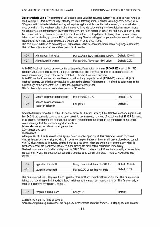
AC70 VC CONTROL FREQUENCY INVERTER MANUAL FUNCTION PARAMETER DETAILED SPECIFICATION
112
Sleep threshold value: This parameter use as a standard value for adjusting system if go to sleep mode when no need working. It is that inverter always standby for sleep detecting, if PID feedback value higher than or equal to PID given setting value is detected, and try to keep holding for a while in setting value around, inverter will start sleep detecting. If the feedback value higher than sleep threshold value during the sleep detecting mode, inverter will reduce the output frequency to lower limit frequency, and keep outputting lower limit frequency for a while, and then reduce to 0Hz, go into sleep mode. If feedback value lower to sleep threshold during above process, sleep detecting will be disable, go back to PID adjusting working. Smaller setting of this parameter, system will go to sleep mode easier. When it is set for 100.0%, the system will not go to sleep mode. This parameter is defined as percentage of PID feedback value to sensor maximum measuring range account for. This function only is enabled in constant pressure PID control.
H-26 Alarm upper limit value Range: Alarm lower limit value-100.0% Default: 100.0%
H-27 Alarm lower limit value Range: 0.0%-Alarm upper limit value Default: 0.0%
While PID feedback reaches or exceeds the setting value, if any output terminals [F-30-F-32] is set as 15, (PID feedback value upper limit alarming), it outputs alarm signal; This parameter is defined as percentage of the maximum measuring range of the sensor that the PID feedback value accounts for. While PID feedback reaches or under the setting value, if any output terminals [F-30-F-32] is set as 16, (PID feedback quantity upper limit alarming), it outputs reaching signal; This parameter is defined as percentage of the largest range of the sensor that the PID feedback quantity accounts for. This function only is enabled in constant pressure PID control.
H-28 Sensor disconnection detection Range: 0.0%-20.0% Default: 0.0%
H-29 Sensor disconnection alarm operation selection
Range: 0,1 Default: 0
When the frequency inverter is in the PID control mode, this function is valid; If the detection feedback signal is less than [H-28], the sensor is deemed to be open circuit. At this moment ,if any one of output terminal [F-30-F-32] is set as‘17’ (sensor disconnect), the output signal is valid; This parameter is defined as the percentage of the sensor maximum range that the feedback signal accounts for. Sensor disconnection alarm running selection 0:Continuous operation 1:Close down In the process of PID adjustment, while system detects sensor open circuit, this parameter is used to choose whether frequency inverter stop working. If choose working on ,frequency inverter will cancel closed-loop control, with PID given values as frequency output; If choose close down, when the system detects the alarm which is mentioned above, the inverter will stop output and display the malfunction information immediately. The feedback sensor malfunction is displayed as "SEn". When it detects the PID feedback quantity is greater than the setting of [H-28], the feedback sensor fault is deemed to be vanish, and system restores PID closed-loop control.
H-30 Upper limit threshold Range: lower limit threshold-100.0% Default: 100.0%
H-31 Lower limit threshold Range:0.0%-upper limit threshold Default: 0.0%
This parameter will limit PID given during upper limit threshold and lower limit threshold range. This parameters is defined the ratio of upper limit threshold, lower limit threshold to maximum measuring range. This function only is enabled in constant pressure PID control.
H-32 Program running mode Range:0-5 Default: 0
0. Single cycle running (time by second) While receiving running instructions, the frequency inverter starts operation from the 1st step speed and direction.

AC70 VC CONTROL FREQUENCY INVERTER MANUAL FUNCTION PARAMETER DETAILED SPECIFICATION
113
The acceleration/deceleration time are selected by parameter [H-35-H-42]; Run time is up to parameter [H-43- H-50]; The time unit is second. While the first step time up, it shifts to the next step speed. The time, direction, acceleration/deceleration time of each step speed can be programmed; While finishing the 8th section speed running, frequency inverter will output "0" frequency. If one step running time is set to zero, it will skip over this step. 1. Continuous cycle running (time by second) After the frequency inverter finishing 8th section speed running, return to the 1st step speed to begin to work for uninterrupted cycles. Running direction and acceleration/deceleration time are selected by the parameter [H-35-H-42]; Run time is set up by parameter [H-43-H-50], the time unit is second. 2: single cycle, continuous running (time by second) After finishing a single cycle running, the frequency inverter running don’t stop. It works on at the final step speed whose running time is not zero. Running direction and acceleration/deceleration time are selected by the parameter [H-35-H-42]; Run time is set up by parameter [H-43-H-50], the time unit is second. 3. Single cycle running (time by minute) Direction and acceleration/deceleration time are selected by parameter [H-35-H-42]; Running time is set up by parameter [H-43-H-50]; The time unit is minute. The others are identical with mode ‘0’. 4: continuous cycle (time by minute) Running direction and acceleration\deceleration time are selected by the parameter [H-35-H-42]; Running time is set up by parameter [H-43-H-50]; The time unit is minute; The others are identical with mode ‘1’. 5: Single cycle, continuous running (time by minute) Running direction and acceleration/deceleration time are selected by the parameter [H-35-H-42]; Running time is set up by parameter [H-50-H-50]; The time unit is minute; The others are identical with mode "1"
........
........
........
........
...
...
........
...........
Output frequency
Output frequency
Output frequency
Time
Time
Continuous cycle
Single cycle,continuous running
Single cycle
T3T2T1T14 T15T1 T2 T3 T4
15X
14X4X
3X
2X
1X 1X
2X
3X
Time
T15T14T4T3T2T1
1X
2X
3X
4X14X
15X
T15T14T4T3T2T1
1X
2X
3X
4X14X
15X

AC70 VC CONTROL FREQUENCY INVERTER MANUAL FUNCTION PARAMETER DETAILED SPECIFICATION
114
H-33 Program run breakpoint restore mode selection
Range: 0,1,2 Default: 0
0: Running at the first step speed 1: Continue to run with breakpoint running frequency and retiming. 2: Continue to run with the breakpoint running frequency and residual time. This parameter defines the restart running mode after break off due to various reasons (stop, fault, power fail). If select 0 mode, inverter restarts running with first step speed. If select 1 mode, inverter restarts running from break of running step, and start timing. If select 2 mode, inverter restarts running from break of running step, and run with residual time after break off.
H-34 Program running state power down memory selection Range: 0,1 Default:0
0: NO power down memory 1: power down memory This parameter defines if inverter will memorize current program running status after power down in program running mode (running step, residual time of current step, acceleration/deceleration and running direction, etc). If select power down memory, and combine with [H-33] parameters can defines next restore program running mode when power on. It need to protect inverter will continue running with before power off running status, this parameters should set to1.
H-35 1 step speed direction and accel/decel time Range: 0-7 Default: 0
H-36 2 step speed direction and accel/decel time
Range: 0-7 Default: 1
H-37 3 step speed direction and accel/decel time
Range: 0-7 Default: 2
H-38 4 step speed direction and accel/decel time
Range: 0-7 Default: 3
H-39 5 step speed direction and accel/decel time
Range: 0-7 Default: 4
H-40 6 step speed direction and accel/decel time
Range: 0-7 Default: 5
H-41 7 step speed direction and accel/decel time
Range: 0-7 Default: 6
H-42 8 step speed direction and accel/decel time
Range: 0-7 Default: 7
In the program running, use to set 8 steps rotation direction and acceleration /deceleration time respectively.
Setting code Description
0 Forward; Acceleration time 1/Deceleration time 1
1 Forward; Acceleration time 2/Deceleration time 2
2 Forward; Acceleration time 3/Deceleration time 3
3 Forward; Acceleration time 4/Deceleration time 4
4 Reverse; Acceleration time 1/Deceleration time 1
5 Reverse; Acceleration time 1/Deceleration time 2

AC70 VC CONTROL FREQUENCY INVERTER MANUAL FUNCTION PARAMETER DETAILED SPECIFICATION
115
6 Reverse; Acceleration time 1/Deceleration time 3
7 Reverse; Acceleration time 1/Deceleration time 4
H-43 1 step speed running time T1 Range: 0.0-6000.0 Default: 10.0
H-44 2 step speed running time T2 Range: 0.0-6000.0 Default: 10.0
H-45 3 step speed running time T3 Range: 0.0-6000.0 Default: 10.0
H-46 4 step speed running time T4 Range: 0.0-6000.0 Default: 10.0
H-47 5 step speed running time T5 Range: 0.0-6000.0 Default: 10.0
H-48 6 step speed running time T6 Range: 0.0-6000.0 Default: 10.0
H-49 7 step speed running time T7 Range: 0.0-6000.0 Default: 10.0
H-50 8 step speed running time T8 Range: 0.0-6000.0 Default: 10.0
Use to set 8 steps speed running time, unit of time is set by [H-32] parameters.
H-51 Differential frequency f in swing frequency Range:0.00Hz-20.00Hz Default:2.00Hz
During the swing frequency operation, the FOR/REV switching function will be forbidden, running direction is programmed after stop only. f1 is the setting value of [F-09]; f2 is the setting value of [F-10]; Acceleration time T1 of the amplitude is the setting value of [F-24]; And the acceleration time T2 of the amplitude is the setting value of [F-25]. The acceleration/deceleration time in swing frequency running is defined by acceleration/deceleration time 1. When using the swing frequency running function, frequency inverter will run with the acceleration/deceleration time 1 to the f1 setting frequency, then begin swing frequency running. While stop, frequency inverter will run for acceleration/deceleration time 1 from the running frequency to stop. Acceleration/deceleration time of the amplitude is defined by acceleration/deceleration time 2. It is defined as the same as acceleration/deceleration time 1. The parameter settings in the swing frequency running should satisfy the following formula request, otherwise display "Err5".
f1>f2+ f
f2≥0.50Hz
0≤ f≤20.00Hz
f
Output frequency
acc time 1runing order
swing frequency running diagram
Time
dec time 1T2T1T2T1T2
f
f f
f
fswing frequency f1
swing frequency f2
H-52 Motor rated power Range: 0.4-1100.0KW Default: ※
H-53 Motor rated frequency
Range: 0-600.00Hz Default: 50.00Hz
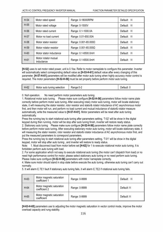
AC70 VC CONTROL FREQUENCY INVERTER MANUAL FUNCTION PARAMETER DETAILED SPECIFICATION
116
H-54 Motor rated speed Range: 0-18000RPM Default: ※
H-55
Motor rated voltage Range: 0-1500V Default: ※
H-56 Motor rated current Range: 0.1-1000.0A Default: ※
H-57 Motor no load current Range: 0.01-650.00A Default: ※
H-58 Motor stator resistor Range: 0.001-65.000Ω Default: ※
H-59 Motor rotator resistor Range: 0.001-65.000Ω Default: ※
H-60 Motor stator inductance Range: 0.1-6500.0mH Default: ※
H-61 Motor rotator mutual inductance
Range: 0.1-6500.0mH Default: ※
[H-52] uses to set motor rated power, unit is 0.1kw. Refer to motor nameplate to configure this parameter. Inverter will automatically select corresponding default value as [H-53-H-61] default value after every changing of this parameter. [H-57-H-61] parameters will be modified after motor auto tuning when highly accuracy motor control is required. The motor parameters [H-52-H-56] must be set properly before perform motor auto tuning.
H-62 Motor auto tuning selection Range:0-2 Default: 0
0. Null operation. No need perform motor parameters auto tuning. 1. Rotational motor auto tuning. Please make sure configure [H-52-H-56] parameters follow motor name plate correctly before perform motor auto tuning. After executing rotary motor auto tuning, motor will locate stationary state, it will measuring the stator resistor, rotor resistor and stator& rotator inductance of AC asynchronous motor first, and then motor will run, and perform no load current and mutual inductance of stator& rotator measure automatically, write the measured value to [H-57-H-61]. Motor parameters will be reset after auto tuning automatically. Press the running key to start rotational auto tuning after parameters setting, ‘T-02’ will be show in the digital keypad during then running, motor will be stop after auto tuning finish, inverter will restore ready status. 2. Stationary auto tuning Please make sure configure [H-52-H-56] parameters follow motor name plate correctly before perform motor auto tuning. After executing stationary motor auto tuning, motor will locate stationary state, it will measuring the stator resistor, rotor resistor and stator& rotator inductance of AC asynchronous motor first, and put the measured parameters to correspond parameters. Press the running key to start rotational auto tuning after parameters setting, ‘T-01’ will be show in the digital keypad, motor will stop after auto tuning , and inverter will restore to ready status. Note: 1. Must disconnect load from motor before set [H-62] for 1 to execute rotational motor auto tuning. It is forbidden perform auto tuning with load. 2. For some application which not easy to execute rotational auto tuning (the motor can’t dispatch from load) or no need high performance control for motor, please select stationary auto tuning or no need perform auto tuning. Please make sure configure [H-52-H-56] parameters with motor nameplate correctly. 4. Make sure motor should stand in stop state before execute the auto tuning, otherwise auto tuning can’t carry out normally. 5. It will alarm E.TE1 fault if stationary auto tuning fails, it will alarm E.TE2 if rotational auto tuning fails.
H-63 Motor magnetic saturation coefficient 1 Range: 0-9999 Default: ※
H-64 Motor magnetic saturation coefficient 2 Range: 0-9999 Default:※
H-65 Motor magnetic saturation coefficient Range: 0-9999 Default:※
[H-63-H-65] parameters use to adjusting the motor magnetic saturation in vector control mode, improve the motor overload capacity and rung stability.

AC70 VC CONTROL FREQUENCY INVERTER MANUAL FUNCTION PARAMETER DETAILED SPECIFICATION
117
H-66 Linkage main station setting Range: 0,1,2 Default: 0
0: Local machine configure as linkage slave station 1: Main station control mode 1. Sent frequency reference and running command of main inverter to slave inverter. 2: Main station control mode 2. Sent output frequency and running command of main inverter to slave inverter. When this frequency configure for main station, it has linking control function, enable to control other AC70 inverter of network synchronous running.
H-67 Local inverter address Range: 1-247 Default: 1
Uses to define communication address of local machine when it has been set for slave one. It makes no sense if it is set for main inverter.
H-68 Data format Range: 0,1,2,3 Default: 3
0: (N,8,1), no check, data bit: 8, stop bit: 1 1: (E,8,1), even parity check, data bit: 8, stop bit: 1 2: (0,8,1), odd parity check, data bit: 8, stop bit: 1 3: (0,8,2), no check, data bit: 8, stop bit: 2
H-69 Baud rate Range:0- 5 Default:3
0:1200bps
1:2400bps
2:4800bps
3:9600bps
4:19200bps
5:38400bps
H-70 Communication setting frequency ratio
Range:0.01-5.00 Default:1.00
Take frequency reference from upper controller multiply this parameter for this machine frequency reference. Modification with proportional scale for given frequency from upper controller is available.
H-71 Time of communication time out Range:0.0-6500.0s Default:10.0s
If the interval time between a communication and the next communication exceeds communication overtime time, it is considered there is communication disconnection fault, malfunction disconnection action mode is decided by the [H-72].
H-72 RS485 communication broken responding mode
Range:0-2 Default: 1
LED“0” digit: RS485 communication broken responding mode 0: giving alarm and free stop When the inverter setting given communication command don’t receive next frame command or any other communication command respond over [H-17] given time, inverter will giving alarm and free stop . 1: No alarm and continue running Inverter don’t make any fault detect, continue running with last communication
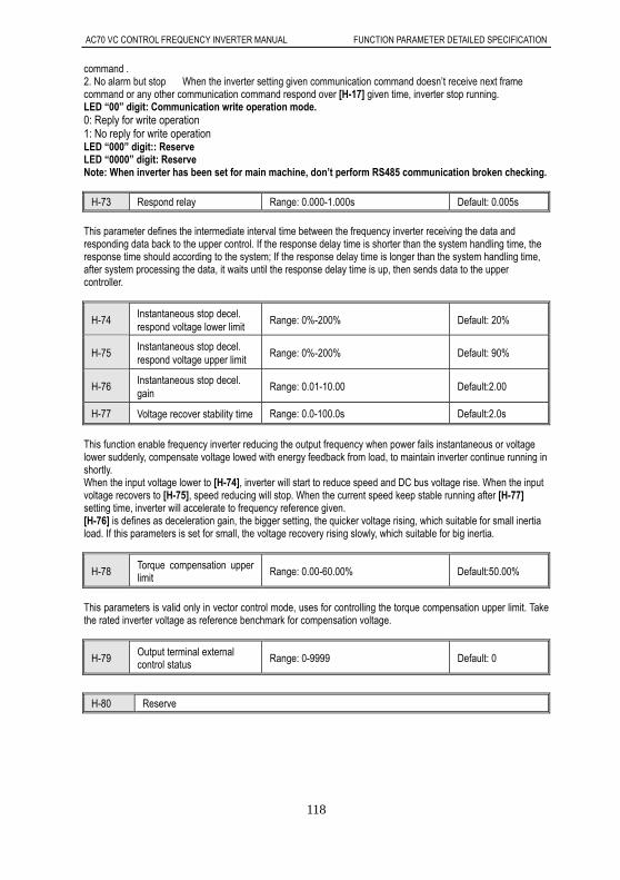
AC70 VC CONTROL FREQUENCY INVERTER MANUAL FUNCTION PARAMETER DETAILED SPECIFICATION
118
command . 2. No alarm but stop When the inverter setting given communication command doesn’t receive next frame command or any other communication command respond over [H-17] given time, inverter stop running. LED “00” digit: Communication write operation mode. 0: Reply for write operation 1: No reply for write operation LED “000” digit:: Reserve LED “0000” digit: Reserve Note: When inverter has been set for main machine, don’t perform RS485 communication broken checking.
H-73 Respond relay Range: 0.000-1.000s Default: 0.005s
This parameter defines the intermediate interval time between the frequency inverter receiving the data and responding data back to the upper control. If the response delay time is shorter than the system handling time, the response time should according to the system; If the response delay time is longer than the system handling time, after system processing the data, it waits until the response delay time is up, then sends data to the upper controller.
H-74 Instantaneous stop decel. respond voltage lower limit
Range: 0%-200% Default: 20%
H-75 Instantaneous stop decel. respond voltage upper limit
Range: 0%-200% Default: 90%
H-76 Instantaneous stop decel. gain
Range: 0.01-10.00 Default:2.00
H-77 Voltage recover stability time Range: 0.0-100.0s Default:2.0s
This function enable frequency inverter reducing the output frequency when power fails instantaneous or voltage lower suddenly, compensate voltage lowed with energy feedback from load, to maintain inverter continue running in shortly. When the input voltage lower to [H-74], inverter will start to reduce speed and DC bus voltage rise. When the input voltage recovers to [H-75], speed reducing will stop. When the current speed keep stable running after [H-77] setting time, inverter will accelerate to frequency reference given. [H-76] is defines as deceleration gain, the bigger setting, the quicker voltage rising, which suitable for small inertia load. If this parameters is set for small, the voltage recovery rising slowly, which suitable for big inertia.
H-78 Torque compensation upper limit Range: 0.00-60.00% Default:50.00%
This parameters is valid only in vector control mode, uses for controlling the torque compensation upper limit. Take the rated inverter voltage as reference benchmark for compensation voltage.
H-79 Output terminal external control status Range: 0-9999 Default: 0
H-80 Reserve

AC70 VC CONTROL FREQUENCY INVERTER MANUAL APPENDIX
119
Appendix 1: Appendix 9.1 Appendix 1: Function Code Simple List
“”: Stand for this parameter can be modified in running mode. “〇”: Stand for this parameter can not be modified in running mode. “×”: Stand for this parameter is read only, can’t be modified. “–”: Stand for factory authority parameters. Veichi setting is available only. “ ”: Stand for this parameter is related to frequ※ ency inverter model. Basic function code group
Code function Function name Setting range and definition Factory
default
property
Refer to page
Communication code
E-00 Control method selection 0: Open loop vector control without PG 1: V/F control mode
1 〇 69 100H
E-01 Running control command channel selection
0: Operator keypad 1: External terminal control 2: RS485 Communications port control
0 〇 69 101H
E-02 Frequency reference given main channel selection
0: Operator keypad digital given 1: Potentiometer of keypad 2: Terminal VS1 analog voltage 0-10V 3: Terminal AS analog current signal 4-20mA 4: Terminal VS2 analog voltage -10-10V 5: Pulse train signal 6: RS485 communication port 7: Up and Down control 8: General PID operation 9: Constant pressure PID control 10: Program running 11: Swing frequency run 12: Terminal selection:
1 〇 69 102H
E-03
Frequency reference
given auxiliary channel
selection
0: Operator keypad digital 1: Potentiometer of keypad 2: Terminal VS1 analog voltage 0-10V 3: Terminal AS analog current signal 4-20mA 4: Terminal VS2 analog voltage -10-10V 5: Pulse train signal 6: RS485 communication port 7: Up and Down control 8: General PID operation 9: Constant pressure PID control 10: Program running
0 〇 71 103H
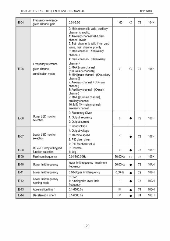
AC70 VC CONTROL FREQUENCY INVERTER MANUAL APPENDIX
120
E-04 Frequency reference given channel gain 0.01-5.00 1.00 〇 72 104H
E-05
Frequency reference
given channel
combination mode
0: Main channel is valid, auxiliary channel is invalid. 1: Auxiliary channel valid,main channel invalid 2: Both channel is valid if non zero value, main channel priority 3: Main channel + K×auxiliary channel) 4: main channel -(K×auxiliary channel) 5: MAX [main channel , (K×auxiliary channel)] 6: MIN [main channel , (K×auxiliary channel)] 7: Auxiliary channel + (K×main channel) 8: Auxiliary channel - (K×main channel) 9: MAX [(K×main channel), auxiliary channel] 10: MIN [(K×main channel), auxiliary channel]
0 〇 72 105H
E-06 Upper LED monitor selection
0: Frequency Given 1: Output frequency 2: Output current 3: Input voltage 4: Output voltage 5: Machine speed 6: PID given given 7: PID feedback value
0 72 106H
E-07 Lower LED monitor selection 1 72 107H
E-08 REV/JOG key of keypad function selection
0: Reverse 1: Jog 0 73 108H
E-09 Maximum frequency 0.01-600.00Hz 50.00Hz 〇 73 109H
E-10 Upper limit frequency lower limit frequency - maximum frequency
50.00Hz 73 10AH
E-11 Lower limit frequency 0.00-Upper limit frequency 0.00Hz 73 10BH
E-12 Lower limit frequency running mode
0: Stop 1: running with lower limit frequency
1 73 10CH
E-13 Acceleration time 1 0.1-6500.0s ※ 74 10DH
E-14 Deceleration time 1 0.1-6500.0s ※ 74 10EH
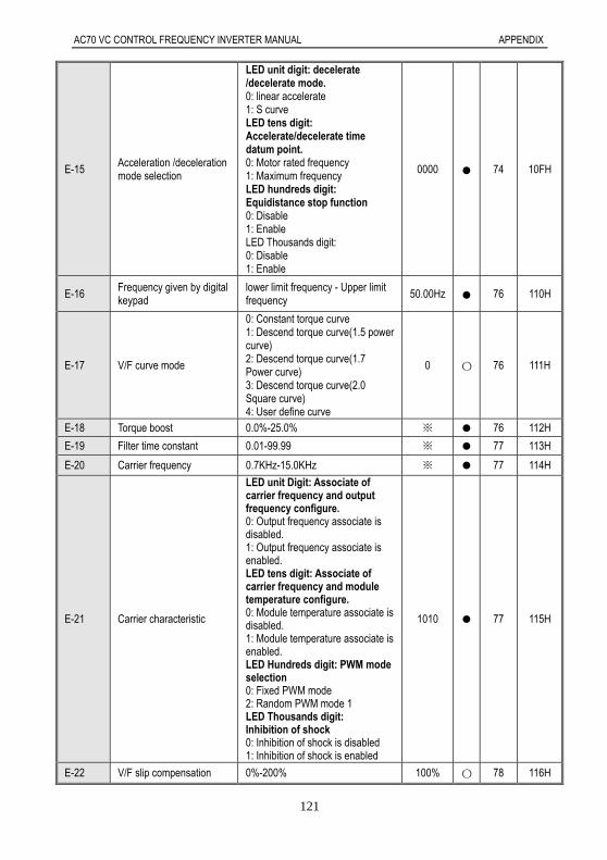
AC70 VC CONTROL FREQUENCY INVERTER MANUAL APPENDIX
121
E-15 Acceleration /deceleration mode selection
LED unit digit: decelerate /decelerate mode. 0: linear accelerate 1: S curve LED tens digit: Accelerate/decelerate time datum point. 0: Motor rated frequency 1: Maximum frequency LED hundreds digit: Equidistance stop function 0: Disable 1: Enable LED Thousands digit: 0: Disable 1: Enable
0000 74 10FH
E-16 Frequency given by digital keypad
lower limit frequency - Upper limit frequency 50.00Hz 76 110H
E-17 V/F curve mode
0: Constant torque curve 1: Descend torque curve(1.5 power curve) 2: Descend torque curve(1.7 Power curve) 3: Descend torque curve(2.0 Square curve) 4: User define curve
0 〇 76 111H
E-18 Torque boost 0.0%-25.0% ※ 76 112H
E-19 Filter time constant 0.01-99.99 ※ 77 113H
E-20 Carrier frequency 0.7KHz-15.0KHz ※ 77 114H
E-21 Carrier characteristic
LED unit Digit: Associate of carrier frequency and output frequency configure. 0: Output frequency associate is disabled. 1: Output frequency associate is enabled. LED tens digit: Associate of carrier frequency and module temperature configure. 0: Module temperature associate is disabled. 1: Module temperature associate is enabled. LED Hundreds digit: PWM mode selection 0: Fixed PWM mode 2: Random PWM mode 1 LED Thousands digit: Inhibition of shock 0: Inhibition of shock is disabled 1: Inhibition of shock is enabled
1010 77 115H
E-22 V/F slip compensation 0%-200% 100% 〇 78 116H
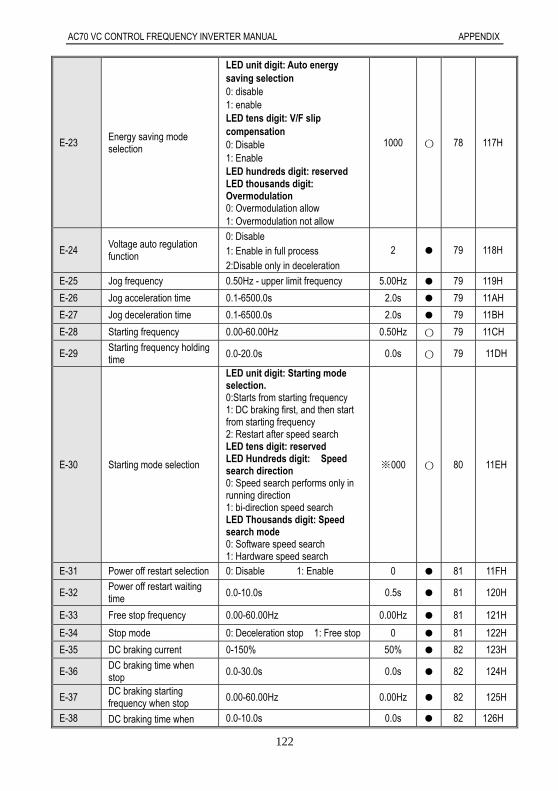
AC70 VC CONTROL FREQUENCY INVERTER MANUAL APPENDIX
122
E-23 Energy saving mode selection
LED unit digit: Auto energy saving selection 0: disable 1: enable LED tens digit: V/F slip compensation 0: Disable 1: Enable LED hundreds digit: reserved LED thousands digit: Overmodulation 0: Overmodulation allow 1: Overmodulation not allow
1000 〇 78 117H
E-24 Voltage auto regulation function
0: Disable 1: Enable in full process 2:Disable only in deceleration
2 79 118H
E-25 Jog frequency 0.50Hz - upper limit frequency 5.00Hz 79 119H
E-26 Jog acceleration time 0.1-6500.0s 2.0s 79 11AH
E-27 Jog deceleration time 0.1-6500.0s 2.0s 79 11BH
E-28 Starting frequency 0.00-60.00Hz 0.50Hz 〇 79 11CH
E-29 Starting frequency holding time 0.0-20.0s 0.0s 〇 79 11DH
E-30 Starting mode selection
LED unit digit: Starting mode selection. 0:Starts from starting frequency 1: DC braking first, and then start from starting frequency 2: Restart after speed search LED tens digit: reserved LED Hundreds digit: Speed search direction 0: Speed search performs only in running direction 1: bi-direction speed search LED Thousands digit: Speed search mode 0: Software speed search 1: Hardware speed search
※000 〇 80 11EH
E-31 Power off restart selection 0: Disable 1: Enable 0 81 11FH
E-32 Power off restart waiting time 0.0-10.0s 0.5s 81 120H
E-33 Free stop frequency 0.00-60.00Hz 0.00Hz 81 121H
E-34 Stop mode 0: Deceleration stop 1: Free stop 0 81 122H
E-35 DC braking current 0-150% 50% 82 123H
E-36 DC braking time when stop 0.0-30.0s 0.0s 82 124H
E-37 DC braking starting frequency when stop 0.00-60.00Hz 0.00Hz 82 125H
E-38 DC braking time when 0.0-10.0s 0.0s 82 126H
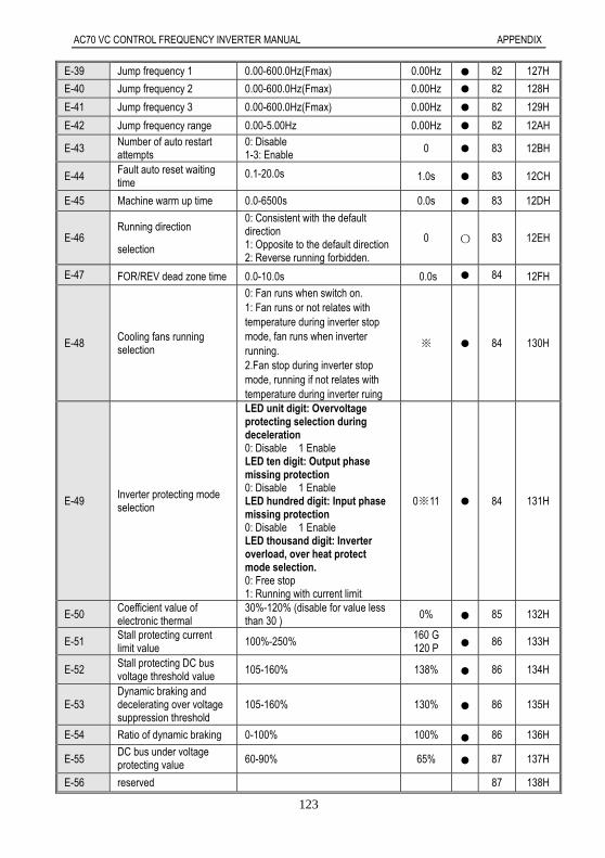
AC70 VC CONTROL FREQUENCY INVERTER MANUAL APPENDIX
123
E-39 Jump frequency 1 0.00-600.0Hz(Fmax) 0.00Hz 82 127H
E-40 Jump frequency 2 0.00-600.0Hz(Fmax) 0.00Hz 82 128H
E-41 Jump frequency 3 0.00-600.0Hz(Fmax) 0.00Hz 82 129H
E-42 Jump frequency range 0.00-5.00Hz 0.00Hz 82 12AH
E-43 Number of auto restart attempts
0: Disable 1-3: Enable 0 83 12BH
E-44 Fault auto reset waiting time
0.1-20.0s 1.0s 83 12CH
E-45 Machine warm up time 0.0-6500s 0.0s 83 12DH
E-46 Running direction
selection
0: Consistent with the default direction 1: Opposite to the default direction 2: Reverse running forbidden.
0 〇 83 12EH
E-47 FOR/REV dead zone time 0.0-10.0s 0.0s 84 12FH
E-48 Cooling fans running selection
0: Fan runs when switch on. 1: Fan runs or not relates with temperature during inverter stop mode, fan runs when inverter running. 2.Fan stop during inverter stop mode, running if not relates with temperature during inverter ruing
※ 84 130H
E-49 Inverter protecting mode selection
LED unit digit: Overvoltage protecting selection during deceleration 0: Disable 1 Enable LED ten digit: Output phase missing protection 0: Disable 1 Enable LED hundred digit: Input phase missing protection 0: Disable 1 Enable LED thousand digit: Inverter overload, over heat protect mode selection. 0: Free stop 1: Running with current limit
0※11 84 131H
E-50 Coefficient value of electronic thermal
30%-120% (disable for value less than 30 ) 0% 85 132H
E-51 Stall protecting current limit value
100%-250% 160 G 120 P 86 133H
E-52 Stall protecting DC bus voltage threshold value
105-160% 138% 86 134H
E-53 Dynamic braking and decelerating over voltage suppression threshold
105-160% 130% 86 135H
E-54 Ratio of dynamic braking 0-100% 100% 86 136H
E-55 DC bus under voltage protecting value 60-90% 65% 87 137H
E-56 reserved 87 138H
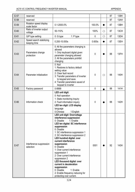
AC70 VC CONTROL FREQUENCY INVERTER MANUAL APPENDIX
124
E-57 reserved 87 139H
E-58 reserved 87 13AH
E-59 Rotation speed display scale factor
0.1-2000.0% 100.0% 87 13BH
E-60 Ratio of inverter output voltage 50-110% 100% 〇 87 13CH
E-61 G/P type setting 0: G type 1: P type 0 〇 87 13DH
E-62 Speed search stabilizing keeping time 0.200-10.000s 0.600s 87 13EH
E-63 Parameters change protection
0: All the parameters changing is allowed 1: Only keyboard digital given parameter changing allowed 2: All the parameters prohibit changing
0 88 13FH
E-64 Parameter initialization
0: Null 1: Restores to factory default setting value 2: Clear fault record 3: Transfer parameters of inverter
to keypad and save. 4: Transfer parameters saved of
keypad to inverter
0 〇 88 140H
E-65 Factory password 0-9999 0 88 141H
E-66 Information check
LED unit digit: 0: Null operation 1: State monitoring inquiry 2: Fault information inquiry LED ten digit: LCD display language 0:Chinese 1:English
0 88 142H
E-67 Interference suppression selection
LED unit digit: Overvoltage interference suppression 0: Disable 1: Enable LED ten digital: SC interference suppression 0: Disable 1: SC interference suppression 1 2: SC interference suppression 2 LED hundred digital: over current interference suppression 0: Disable 1: Over current interference suppression 1 2: Over current interference suppression 2 LED thousand digital: over current in deceleration suppression 0: Disable 1: Enable 2: Enable frequency reducing for protecting over current.
0001 92 143H

AC70 VC CONTROL FREQUENCY INVERTER MANUAL APPENDIX
125
External terminal parameters
Code function
Function name Setting range and define Factory default
property
Refer to page
Communication code
F-01 Input signal selection 1
(X1)
0: Invalid 1: Forward jog operation 2: Reverse jog operation 3: Free stop 4: Fault reset 5: Multi steps speed control 1 6: Multi steps speed control 2 7: Multi steps speed control 3 8: Multi steps speed control 4 9: UP/Down running frequency increasing UP 10:UP/Down running frequency decreasing DW 11: Three wire operation control D (X) 12: PID control cancel 13: External fault alarm 14: Acceleration/deceleration time selection terminal 1. 15:Acceleration/deceleration time selection terminal 2 16: Frequency main channel selection terminal 1 17: Frequency main channel selection terminal 2 18: Frequency main channel selection terminal 3 19: Frequency main channel selection terminal 4 20: Program running pause 21: Program restart 22: Timer trigger terminal 23: Timer reset terminal 24: Counter reset terminal 25:Counter clock input terminal 26:Only terminal control channel is enabled selection 27: Forward running 28: Reverse running
27 〇 93 201H
F-02 Input signal selection2
(X2) 28 〇 93 202H
F-03 Input signal selection 3
(X3) 1 〇 93 203H
F-04 Input signal selection 4
(X4) 2 〇 93 204H
F-05 Input signal selection 5
(X5) 3 〇 93 205H
F-06 Input signal selection 6
(X6) 4 〇 93 206H

AC70 VC CONTROL FREQUENCY INVERTER MANUAL APPENDIX
126
F-07 Input signal respond mode
selection
LED unit digit: Free stop terminal recover mode 0: Recover to original command with speed search function. 1:Don’t recover to original command after free stop terminal disconnecting. 2: Recover to original command without speed search function. LED ten digit: UP and DW terminal control starting frequency setting 0: Runs with UP/DW terminal adjusting without save the frequency record after power loss. 1: Run to last stop moment frequency and then perform UP/DW adjusting. 2: Runs to preset frequency[F-70] first, and then execute UP/DW adjusting. LED hundred digit: STOP/RESE of keypad effective range selection. 0: STOP/RESE key valid only when under keypad control 1: STOP/RESE key valid under any run command source LED thousand digit: Terminal running mode selection after fault reset 0: Start inverter running directly after power on in terminal control mode 1: Stop first and then start in terminal control mode.
0001 〇 94 207H

AC70 VC CONTROL FREQUENCY INVERTER MANUAL APPENDIX
127
F-08 Terminal running control mode
LED unit digit: Terminal control
mode selection 0: Standard running control mode 1: 2wire running control mode 2: 2 wire control mode 1 3: 3 wire control mode 2 4: 3 wire control mode 3 5: 3 wire control mode 4
LED ten digit:reserved
LED hundred digit:reserved
LED thousand: reserved
0000 〇 95 208H
F-09 1 step speed setting 1X
0.00Hz-upper limit frequency
30.00Hz 97 209H
F-10 2 step speed setting 2X 25.00Hz 97 20AH
F-11 3 step speed setting 3X 40.00Hz 97 20BH
F-12 4 step speed setting 4X 50.00Hz 97 20CH
F-13 5 step speed setting 5X 50.00Hz 97 20DH
F-14 6 step speed setting 6X 40.00Hz 97 20EH
F-15 7 step speed setting 7X 25.00Hz 97 20FH
F-16 8 step speed setting 8X 10.00Hz 97 210H
F-17 reserved 98 211H
F-18 reserved 98 212H
F-19 Speed search tracking
speed 0.1-10.0% 0.2% 〇 98 213H
F-20 Voltage stores time 0.10S-10.00S 0.60s 〇 98 214H
F-21 Speed search respond current threshold value 10%-200% 120% 〇 98 215H
F-22 Frequency reducing acceleration time 0.1-6500.0s 2.0s 98 216H
F-23 Frequency reducing acceleration time 0.1-6500.0s 0.3s 98 217H
F-24 Acceleration time 2
0.1-6500.0s
※ 99 218H
F-25 Deceleration time 2 ※ 99 219H
F-26 Acceleration time 3 ※ 99 21AH
F-27 Deceleration time 3 ※ 99 21BH
F-28 Acceleration time 4 ※ 99 21CH
F-29 Deceleration time 4 ※ 99 21DH

AC70 VC CONTROL FREQUENCY INVERTER MANUAL APPENDIX
128
F-30 Relay output terminal
(TA,TB,TC)
0: Zero frequency (standby state) 1: Fault alarm 1. (Including fault auto reset period. ) 2: Fault alarm 2. (Not includes fault auto reset period.) 3: Frequency arriving detection 4: Frequency level detection 5: Running statues 6: Reverse running 7: Under voltage of inverter 8: Overload pre-alarm 9: Output frequency reach upper limit frequency 10. Output frequency reach lower limit frequency 11. External fault stop 12. Timer times up 13. Counter reach maximum values 14. Counter reach setting values 15. PID feedback upper limit alarm 16. PID feedback lower limit alarm 17. Sensor broken 18.Program running cycle completed 19.Program running step completed 20:Dynamic braking processing 21: Output terminal control by external 22. Fault alarm 1. (Including fault auto reset period,including fault-LU1 )
1 99 21EH
F-31 Output terminal Y1 4 99 21FH
F-32 Output terminal Y2 7 99 220H
F-33 Frequency arriving detect bias 0.00-50.00Hz 1.00Hz 101 221H
F-34 Output frequency level detection 0.00-600.0Hz 30.00Hz 101 222H
F-35 Output frequency level detecting relay time 0.0-20.0s 0.0s 101 223H
F-36 Overload pre-alarm level 50-200% 150% 101 224H
F-37 Overload pre-alarm delay time 0.0-20.0s 1.0s 101 225H
F-38 Timer setting value 1-65000s 1s 101 226H
F-39 Counter maximum value 1-65000 1000 102 227H
F-40 Counter setting value 1- Counter maximum value 100 102 228H
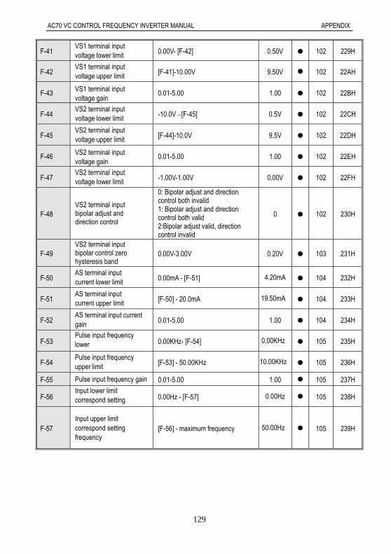
AC70 VC CONTROL FREQUENCY INVERTER MANUAL APPENDIX
129
F-41 VS1 terminal input voltage lower limit 0.00V- [F-42] 0.50V 102 229H
F-42 VS1 terminal input voltage upper limit [F-41]-10.00V 9.50V 102 22AH
F-43 VS1 terminal input voltage gain
0.01-5.00 1.00 102 22BH
F-44 VS2 terminal input voltage lower limit -10.0V –[F-45] 0.5V 102 22CH
F-45 VS2 terminal input voltage upper limit [F-44]-10.0V 9.5V 102 22DH
F-46 VS2 terminal input voltage gain
0.01-5.00 1.00 102 22EH
F-47 VS2 terminal input voltage lower limit -1.00V-1.00V 0.00V 102 22FH
F-48 VS2 terminal input bipolar adjust and direction control
0: Bipolar adjust and direction control both invalid 1: Bipolar adjust and direction control both valid 2:Bipolar adjust valid, direction control invalid
0 102 230H
F-49 VS2 terminal input bipolar control zero hysteresis band
0.00V-3.00V 0.20V 103 231H
F-50 AS terminal input current lower limit 0.00mA - [F-51] 4.20mA 104 232H
F-51 AS terminal input current upper limit [F-50] - 20.0mA 19.50mA 104 233H
F-52 AS terminal input current gain 0.01-5.00 1.00 104 234H
F-53 Pulse input frequency lower 0.00KHz- [F-54] 0.00KHz 105 235H
F-54 Pulse input frequency upper limit [F-53] - 50.00KHz 10.00KHz 105 236H
F-55 Pulse input frequency gain 0.01-5.00 1.00 105 237H
F-56 Input lower limit correspond setting 0.00Hz - [F-57] 0.00Hz 105 238H
F-57 Input upper limit correspond setting frequency
[F-56] - maximum frequency 50.00Hz 105 239H

AC70 VC CONTROL FREQUENCY INVERTER MANUAL APPENDIX
130
F-58 Input signal characteristic selection
LED unit digit: VS1 input characteristic selection 0: Positive characteristic 1: Negative characteristic LED ten digit: AS input characteristic selection 0: Positive characteristic 1: Negative characteristic LED hundred digit: VS2 input characteristic selection 0: Positive characteristic 1: Negative characteristic LED thousand digit: Pulse input characteristic selection 0: Positive characteristic 1: Negative characteristic
0000 105 23AH
F-59 Terminal analog input filtering time constant 0.01-5.00 0.50 106 23BH
F-60 Output terminal(AO1)selection
0: Output signal disable 1: Output frequency/speed 2: Output current 3: Given frequency/speed reference 4: PID given value 5: PID feedback value 6: DC bus voltage 7: Output voltage
1 106 23CH
F-61 Output terminal(AO2)selection
3 106 23DH
F-62 Analog output signal selection
LED unit digit: A02 output signal
mode selection 0: Frequency pulse train output 1: 0-20mA 2: 4-20mA 3: 0-10V
LED ten digit: A01 output signal
mode selection 0: 0-10V 1: 0-20mA 2: 4-20mA
LED hundred digit: reserved
LED thousand digit: reserved
0003 107 23EH
F-63 AO1 output signal gain
25%-200% 100% 107 23FH
F-64 AO2 output signal gain
25%-200% 100% 107 240H
F-65 AO1 output signal zero adjust -10.0%-10.0% 0.0% 107 241H
F-66 AO2 output signal zero adjust
-10.0%-10.0% 0.0% 107 242H

AC70 VC CONTROL FREQUENCY INVERTER MANUAL APPENDIX
131
F-67 Keyboard potentiometer Input voltage lower limit 0.00V - [F-68] 0.20V 107 243H
F-68 Keyboard potentiometer Input voltage upper limit [F-67] - 5.50V 4.80V 107 244H
F-69 Keyboard potentiometer gain
0.00-5.00 1.00 107 245H
F-70 UP/DW terminal preset frequency 0.00Hz - upper limit frequency 0.00Hz 108 246H
F-71 UP/DW Power-off memorized frequency 0.00Hz - upper limit frequency 0.00Hz 〇 108 247H
Special function parameters
Code function Function name Setting range and define
Factory default
property
Refer to page
Communication code
H-01 User setting voltage V1 0.0% -[H-03] 3.0% 〇 108 301H
H-02 User setting frequency F1
0.0Hz-[H-04] 1.00Hz 〇 108 302H
H-03 User setting voltage V2 [H-01-H-05] 28.0% 〇 108 303H
H-04 User setting frequency F2
[H-02-H-06] 10.00Hz 〇 108 304H
H-05 User setting voltage V3 [H-03-H-07] 55.0% 〇 108 305H
H-06 User setting frequency F3
[H-04-H-08] 25.00Hz 〇 108 306H
H-07 User setting voltage V4 [H-05-H-09] 80.0% 〇 108 307H
H-08 User setting frequency F4
[H-06-H-10] 37.50Hz 〇 108 308H
H-09 User setting voltage V5 [H-07]-100.0% 100.0% 〇 108 309H
H-10 User setting frequency F5
[H-08]-maximum frequency 50.00Hz 〇 108 30AH
H-11 PID output characteristic 0: Positive characteristic 1: Negative characteristic 0 〇 109 30BH
H-12 PID controller given signal sources
0: Keypad potentiometer 1: PID keypad digital given 2: External terminal VS1:0-10V 3: External terminal AS: 4-20mA 4: External terminal VS2 5: External pulse signal 6: RS485 interface
1 〇 109 30CH
H-13 PID controller feedback signal source
0: External terminal VS1:0-10V 1: External terminal AS: 4-20mA 2: External terminal VS2 ( bipolar invalid) 3: External pulse signal
1 〇 109 30DH
H-14 PID preset frequency 0.00Hz-upper limit frequency 0.00Hz 〇 110 30EH
H-15 PID preset frequency running time
0.0-6500.0s 0.0s 110 30FH
H-16 PID keypad digital given 0.0-100.0% 50.0% 110 310H
H-17 PID channel gain 0.01-5.00 1.00 110 311H
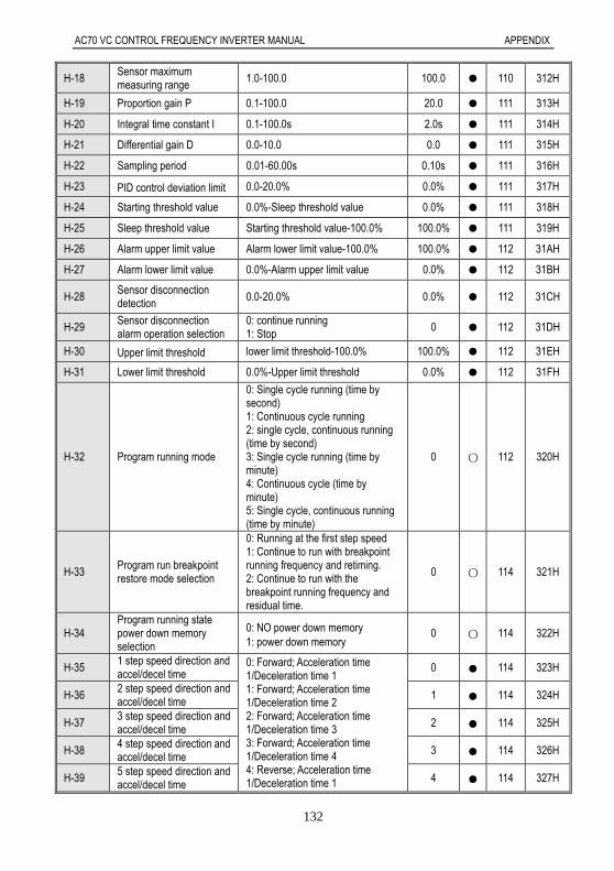
AC70 VC CONTROL FREQUENCY INVERTER MANUAL APPENDIX
132
H-18 Sensor maximum measuring range 1.0-100.0 100.0 110 312H
H-19 Proportion gain P 0.1-100.0 20.0 111 313H
H-20 Integral time constant I 0.1-100.0s 2.0s 111 314H
H-21 Differential gain D 0.0-10.0 0.0 111 315H
H-22 Sampling period 0.01-60.00s 0.10s 111 316H
H-23 PID control deviation limit 0.0-20.0% 0.0% 111 317H
H-24 Starting threshold value 0.0%-Sleep threshold value 0.0% 111 318H
H-25 Sleep threshold value Starting threshold value-100.0% 100.0% 111 319H
H-26 Alarm upper limit value Alarm lower limit value-100.0% 100.0% 112 31AH
H-27 Alarm lower limit value 0.0%-Alarm upper limit value 0.0% 112 31BH
H-28 Sensor disconnection detection 0.0-20.0% 0.0% 112 31CH
H-29 Sensor disconnection alarm operation selection
0: continue running 1: Stop
0 112 31DH
H-30 Upper limit threshold lower limit threshold-100.0% 100.0% 112 31EH
H-31 Lower limit threshold 0.0%-Upper limit threshold 0.0% 112 31FH
H-32 Program running mode
0: Single cycle running (time by second) 1: Continuous cycle running 2: single cycle, continuous running (time by second) 3: Single cycle running (time by minute) 4: Continuous cycle (time by minute) 5: Single cycle, continuous running (time by minute)
0 〇 112 320H
H-33 Program run breakpoint restore mode selection
0: Running at the first step speed 1: Continue to run with breakpoint running frequency and retiming. 2: Continue to run with the breakpoint running frequency and residual time.
0 〇 114 321H
H-34 Program running state power down memory selection
0: NO power down memory 1: power down memory
0 〇 114 322H
H-35 1 step speed direction and accel/decel time
0: Forward; Acceleration time 1/Deceleration time 1 1: Forward; Acceleration time 1/Deceleration time 2 2: Forward; Acceleration time 1/Deceleration time 3 3: Forward; Acceleration time 1/Deceleration time 4 4: Reverse; Acceleration time 1/Deceleration time 1
0 114 323H
H-36 2 step speed direction and accel/decel time
1 114 324H
H-37 3 step speed direction and accel/decel time 2 114 325H
H-38 4 step speed direction and accel/decel time 3 114 326H
H-39 5 step speed direction and accel/decel time
4 114 327H
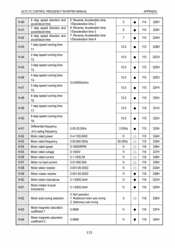
AC70 VC CONTROL FREQUENCY INVERTER MANUAL APPENDIX
133
H-40 6 step speed direction and accel/decel time
5: Reverse; Acceleration time 1/Deceleration time 2 6: Reverse; Acceleration time 1/Deceleration time 3 7: Reverse; Acceleration time 1/Deceleration time 4
5 114 328H
H-41 7 step speed direction and accel/decel time 6 114 329H
H-42 8 step speed direction and accel/decel time
7 114 32AH
H-43 1 step speed running time
T1
0.0-6000s(min)
10.0 115 32BH
H-44 2 step speed running time
T2 10.0 115 32CH
H-45 3 step speed running time
T3 10.0 115 32DH
H-46 4 step speed running time
T4 10.0 115 32EH
H-47 5 step speed running time
T5 10.0 115 32FH
H-48 6 step speed running time
T6 10.0 115 330H
H-49 7 step speed running time
T7 10.0 115 331H
H-50 8 step speed running time
T8 10.0 115 332H
H-51 Differential frequency
∆f in swing frequency 0.00-20.00Hz 2.00Hz 115 333H
H-52 Motor rated power 0.4-1100.0KW ※ 〇 115 334H
H-53 Motor rated frequency 0.00-600.00Hz 50.00Hz 〇 115 335H
H-54 Motor rated speed 0-18000RPM ※ 〇 116 336H
H-55 Motor rated voltage 0-1500V ※ 〇 116 337H
H-56 Motor rated current 0.1-1000.0A ※ 〇 116 338H
H-57 Motor no load current 0.01-650.00A ※ 〇 116 339H
H-58 Motor stator resistor 0.001-65.000Ω ※ 〇 116 33AH
H-59 Motor rotator resistor 0.001-65.000Ω ※ 116 33BH
H-60 Motor stator inductance 0.1-6500.0mH ※ 116 33CH
H-61 Motor rotator mutual inductance 0.1-6500.0mH ※ 116 33DH
H-62 Motor auto tuning selection 0: Null operation. 1: Rotational motor auto tuning. 2: Stationary auto tuning
0 〇 116 33EH
H-63 Motor magnetic saturation coefficient 1
0-9999 ※ 116 33FH
H-64 Motor magnetic saturation coefficient 2 0-9999 ※ 116 340H
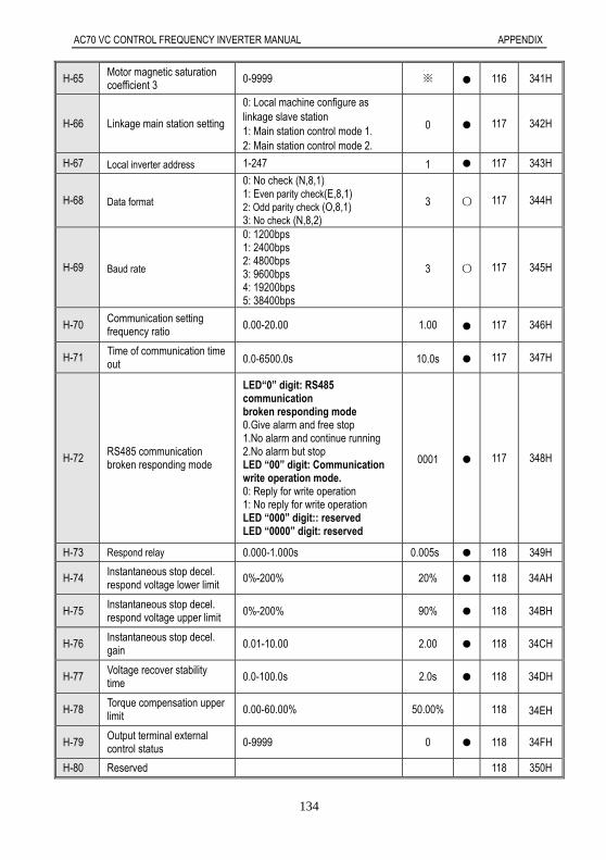
AC70 VC CONTROL FREQUENCY INVERTER MANUAL APPENDIX
134
H-65 Motor magnetic saturation coefficient 3
0-9999 ※ 116 341H
H-66 Linkage main station setting
0: Local machine configure as linkage slave station 1: Main station control mode 1. 2: Main station control mode 2.
0 117 342H
H-67 Local inverter address 1-247 1 117 343H
H-68 Data format
0: No check (N,8,1) 1: Even parity check(E,8,1) 2: Odd parity check (O,8,1) 3: No check (N,8,2)
3 〇 117 344H
H-69 Baud rate
0: 1200bps 1: 2400bps 2: 4800bps 3: 9600bps 4: 19200bps 5: 38400bps
3 〇 117 345H
H-70 Communication setting frequency ratio 0.00-20.00 1.00 117 346H
H-71 Time of communication time out 0.0-6500.0s 10.0s 117 347H
H-72 RS485 communication broken responding mode
LED“0” digit: RS485 communication broken responding mode 0.Give alarm and free stop 1.No alarm and continue running 2.No alarm but stop LED “00” digit: Communication write operation mode. 0: Reply for write operation 1: No reply for write operation LED “000” digit:: reserved LED “0000” digit: reserved
0001 117 348H
H-73 Respond relay 0.000-1.000s 0.005s 118 349H
H-74 Instantaneous stop decel. respond voltage lower limit
0%-200% 20% 118 34AH
H-75 Instantaneous stop decel. respond voltage upper limit 0%-200% 90% 118 34BH
H-76 Instantaneous stop decel. gain 0.01-10.00 2.00 118 34CH
H-77 Voltage recover stability time
0.0-100.0s 2.0s 118 34DH
H-78 Torque compensation upper limit 0.00-60.00% 50.00% 118 34EH
H-79 Output terminal external control status 0-9999 0 118 34FH
H-80 Reserved 118 350H

AC70 VC CONTROL FREQUENCY INVERTER MANUAL APPENDIX
135
Appendix 2: RS485 Communication Protocol1 Communication ProtocolAC70 series frequency inverter can select the RS485 communication interface. The international standard ModBuscommunication protocol is adopted for master-slave communication. The consumer can carry out centralized control byPC/PLC, upper machine, main station frequency inverter etc (Setting of the frequency inverter control command,running frequency, relative function parameters modification, frequency inverter working state and malfunctioninformation monitoring etc.. to adapt to the special application requirements.
2 Protocol ContentThis ModBus protocol defines the information content and format of asynchronous transmission in seriescommunication. It includes: host machine polling, broadcast and the format of slave machine response. Host machinedata frame includes: slave machine address (or broadcast address), ask action code, data and fault check. Slavemachine response is same structure: action check, back data and fault check. If slave machine meet fault while acceptframe, or can’t compete the action asked, fault information will be feed back to host machine.
3 Application ModeAC70 series frequency inverter controls network for “single host machine and many slave machines” withRS232/RS485.Remote RS485 communication needs shield cable and shield grounding.For long distance communication, we suggest to open J6 and add 120Ωresistance to prevent signal reflection.
4 Main Line Structure1, Port mode: RS485 port2, Transmission mode: Asynchronous series, half duplex transmission mode. At same time, one of the host machineand slave machine sends data, anther receives data. Data is sent one by one frame as report form in asynchronousseries communication.3, Topological structure: One host machine with several slave machines. Range of slave machine address is 1 to 247.O is broadcast address. Every slave machine address is only one. It is the base of ModBus series communication.
5 Protocol ExplainAC70 series frequency inverter communication protocol is main-slave ModBus communication protocol ofasynchronous series. In the net, only the host machine can set up protocol “inquire/ order”. Slave machines can onlyrespond to host machine. Host machine means PC, main frequency inverter, industrial control equipment or PLC…Slave machines are AC70 frequency inverters and other control equipments with same communication protocol. Hostmachine can communicate with only one slave machine or broadcast to all slave machines. Slave machine needfeedback every “inquire/order” of host machine, but no need feedback broadcast.5.1 Communication frame structureThe ModBus protocol communication data format of AC70 series frequency inverter is RTU (remote terminal unit) mode.Communication data format is as follows:The byte composition: Include initiation bit, 8 data bit, check bit and stop bit.
Initiationbit Bit1 Bit2 Bit3 Bit4 Bit5 Bit6 Bit7 Bit8
No check bit
Even check bit
Odd check
stop bit
In RTU mode, it always starts after at least 3.5 byte transmission time which is easy realized under Baud rate. And nextdata is: slave machine address, operation order code, data and CRC check. Every domain transmission is hexadecimal0...9,A...F. Network equipment detects the network bus unceasingly, including the interval time. While receiving the firstdomain (address information, each network equipments carry out decoding to judge whether the byte is for itself. Whilethe final byte transmission is completed, there will be at least 3.5 bytes transmission time interval to indicate that thisframe is over. Then a new information’ transmission can begin
One frame message must be transmitted as a continued data flow. If there is a pause over 1.5 byte before the end, thereceiving equipment will clear the half-baked information. And the next byte will be considered as the address domain of

AC70 VC CONTROL FREQUENCY INVERTER MANUAL APPENDIX
136
a new frame. Similarly, if the interval between a new frame start-up and the former frame is smaller than 3.5 byte time,the receiving equipment will think that it is the former one frame continuation. Because of the jumbled frame, finallyCRC checking value is incorrect, what leads to the communication mistake.RTU frame’s standard structure:
Frame START Transmission time of 3.5 bytes
Slave machine addressCommunication address:0~247(decimal)(0 is broadcast address)
Function code CMD03H:read slave machine parameter06H: write slave machine parameter08H:circuit auto-detection
Data domainDATA(N-1)…DATA(0)
parameter address, parameter number, parameter values ,
CRC CHK low-orderDetecting value:16 bit CRC check value
CRC CHK high-orderFrame ending transmission time of 3.5 bytes
5.2 Order code and communication data description5.2.1 Order code:03H, read N word (can continue reading 5 words at most)For example:A frequency inverter who is slave machine with address 01 H and memory initial address 0101H([E-01])reads 3 words continuously. Then the structure of that frame is described as follows:RTU host machine order information
START Transmission time of 3.5 bytes
Slave machine address 01HOrder code 03H
Start address high-order 01H
Start address low-order 01H
Data number high-order 00H
Data number low-order 03HCRC CHK low-order 55HCRC CHK high-order F7H
END Transmission time of 3.5 bytes
RTU Slave machine responding information (normal)
START Transmission time of 3.5 bytes
Slave machine address 01H
Order code 03H
Byte number low-order 06H
Data address 0101H high-order 00H
Data address 0101H low-order 02H
Data address 0102H high-order 00H
Data address 0102H low-order 00H
Data address 0103H high-order 00H
Data address 0103H low-order 06H
CRC CHK low-order D8H
CRC CHK high-order B7H
END Transmission time of 3.5 bytes

AC70 VC CONTROL FREQUENCY INVERTER MANUAL APPENDIX
137
RTU Slave machine responding information (abnormal)
START Transmission time of 3.5 bytes
Slave machine address 01HOrder code 83H
Error code 04HCRC CHK low-order 40HCRC CHK high-order F3H
END Transmission time of 3.5 bytes
5.2.2 Order code:06H, write a Word.Function: write a word data in the designated data address. It can be used to revise the frequency inverter parameters.For example: 5000 (1388 H. is written into 0110H ([E-16]) address of slave frequency inverter with address 02H. Thenthe structure of this frame is described as follows:RTU host machine order information
START Transmission time of 3.5 bytesSlave machine address 02H
Order code 06HWrite data address high-order 01HWrite data address low-order 10H
Data content high-order 13HData content low-order 88HCRC CHK low-order 84HCRC CHK high-order 96H
END Transmission time of 3.5 bytesRTU Slave machine responding information (normal)
START Transmission time of 3.5 bytesSlave machine address 02H
Order code 06HWrite data address high-order 01HWrite data address low-order 10H
Data content high-order 13HData content low-order 88H
CRC CHK low-order 84HCRC CHK high-order 96H
END Transmission time of 3.5 bytesRTU Slave machine responding information (abnormal)
START Transmission time of 3.5 bytesSlave machine address 02H
Order code 86HError code 01H
CRC CHK low-order 73HCRC CHK high-order A0H
END Transmission time of 3.5 bytes5.2.3 Order code:08H, circuit auto-detectionFunction: Send back the slave machine responding information which is identical with the host machine commandinformation. It is used to check whether the signal transmission between the host machine and slave machine is regularor not. The checking code and the data can be set freely.RTU Host machine command information
START Transmission time of 3.5 bytesSlave machine address 01H
Order code 08HDetecting code high-order 00HDetecting code low-order 00H
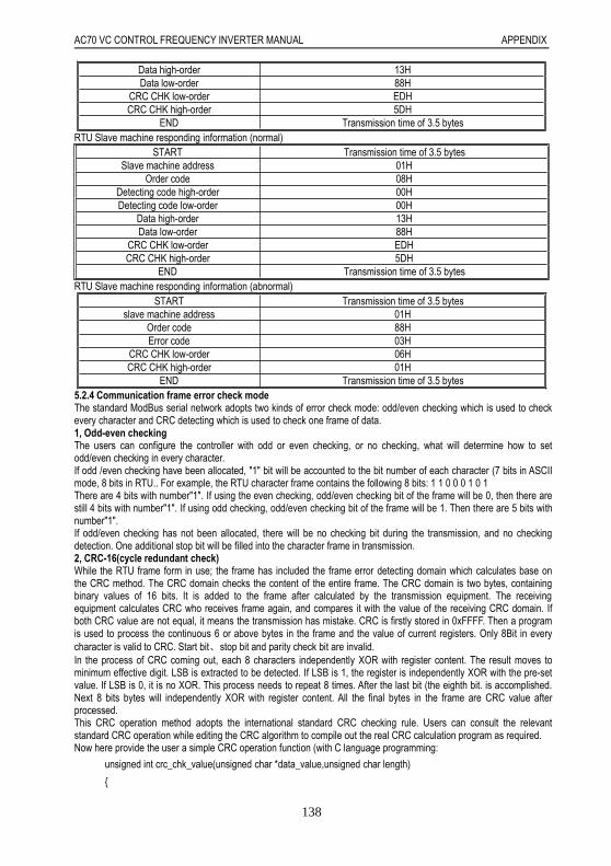
AC70 VC CONTROL FREQUENCY INVERTER MANUAL APPENDIX
138
Data high-order 13HData low-order 88H
CRC CHK low-order EDHCRC CHK high-order 5DH
END Transmission time of 3.5 bytesRTU Slave machine responding information (normal)
START Transmission time of 3.5 bytesSlave machine address 01H
Order code 08HDetecting code high-order 00HDetecting code low-order 00H
Data high-order 13HData low-order 88H
CRC CHK low-order EDHCRC CHK high-order 5DH
END Transmission time of 3.5 bytesRTU Slave machine responding information (abnormal)
START Transmission time of 3.5 bytesslave machine address 01H
Order code 88HError code 03H
CRC CHK low-order 06HCRC CHK high-order 01H
END Transmission time of 3.5 bytes5.2.4 Communication frame error check modeThe standard ModBus serial network adopts two kinds of error check mode: odd/even checking which is used to checkevery character and CRC detecting which is used to check one frame of data.1, Odd-even checkingThe users can configure the controller with odd or even checking, or no checking, what will determine how to setodd/even checking in every character.If odd /even checking have been allocated, "1" bit will be accounted to the bit number of each character (7 bits in ASCIImode, 8 bits in RTU.. For example, the RTU character frame contains the following 8 bits: 1 1 0 0 0 1 0 1There are 4 bits with number"1". If using the even checking, odd/even checking bit of the frame will be 0, then there arestill 4 bits with number"1". If using odd checking, odd/even checking bit of the frame will be 1. Then there are 5 bits withnumber"1".If odd/even checking has not been allocated, there will be no checking bit during the transmission, and no checkingdetection. One additional stop bit will be filled into the character frame in transmission.2, CRC-16(cycle redundant check)While the RTU frame form in use; the frame has included the frame error detecting domain which calculates base onthe CRC method. The CRC domain checks the content of the entire frame. The CRC domain is two bytes, containingbinary values of 16 bits. It is added to the frame after calculated by the transmission equipment. The receivingequipment calculates CRC who receives frame again, and compares it with the value of the receiving CRC domain. Ifboth CRC value are not equal, it means the transmission has mistake. CRC is firstly stored in 0xFFFF. Then a programis used to process the continuous 6 or above bytes in the frame and the value of current registers. Only 8Bit in everycharacter is valid to CRC. Start bit、stop bit and parity check bit are invalid.In the process of CRC coming out, each 8 characters independently XOR with register content. The result moves tominimum effective digit. LSB is extracted to be detected. If LSB is 1, the register is independently XOR with the pre-setvalue. If LSB is 0, it is no XOR. This process needs to repeat 8 times. After the last bit (the eighth bit. is accomplished.Next 8 bits bytes will independently XOR with register content. All the final bytes in the frame are CRC value afterprocessed.This CRC operation method adopts the international standard CRC checking rule. Users can consult the relevantstandard CRC operation while editing the CRC algorithm to compile out the real CRC calculation program as required.Now here provide the user a simple CRC operation function (with C language programming:
unsigned int crc_chk_value(unsigned char *data_value,unsigned char length)

AC70 VC CONTROL FREQUENCY INVERTER MANUAL APPENDIX
139
unsigned int crc_value=0xFFFF;
int i;
while(length--)
crc_value^=*data_value++;
for(i=0;i<8;i++)
if(crc_value&0x0001)
crc_value=(crc_value>>1)^0xa001;
else
crc_value=crc_value>>1;
return(crc_value);
5.2.5 Communication data address definitionIt is used to control frequency inverter operation, get state information and parameter setting of frequency inverter.
(1.AC70 serial function parameter address express rulesTake frequency inverter function parameter serial numbers as register address which are divided into the high byte andthe low byte two parts. The high byte expresses the function parameter group serial numbers. The byte expresses theinner serial numbers of each function parameter group. All need to be changed to hexadecimal.Address domain high byte definition:x1xxH:basic parameter group (E group)x2xxH:external terminal parameter group(F group)x3xxH:dedicated function parameter group (H group).xCxxH: monitoring parameter group (C group).xExxH: fault information group (ER group).Attention: due to possibility that the parameters are frequently rewritten exists in the communication, EEPROM arefrequently stored. So its lifetime is cut down. As for the consumer, some function is unnecessarily to store in thecommunication mode, only require to changing the value of RAM inner, can satisfy the usage requirement. As AC70communication protocol stipulates, when it use writing order (06 H), if the parameter function code address domainhighest digit is 0, merely write in the frequency inverter RAM, power down without storing, if the parameter functioncode address high half digit is 1, write in EEPROM, namely power off with storing.For example, rewriting the function parameter [E-16], not depositing to EEPROM, address expresses for 0110H,depositing to EEPROM, address expresses for 1110H.Only write in the frequency inverter RAM, power down without storing.
START Transmission time of 3.5 bytes
Slave machine address 02H
Order code 06H
Write data address high-order 01H
Write data address low-order 10H
Data content high-order 13H
Data content low-order 88H

AC70 VC CONTROL FREQUENCY INVERTER MANUAL APPENDIX
140
CRC CHK low-order 84H
CRC CHK high-order 96H
END Transmission time of 3.5 bytes
Write in EEPRAM, power off with storing.
START Transmission time of 3.5 bytes
Slave machine address 02H
Order code 06H
Write data address high-order 11H
Write data address low-order 10H
Data content high-order 13H
Data content low-order 88H
CRC CHK low-order 84H
CRC CHK high-order 96H
END Transmission time of 3.5 bytes
(2) Other communication parameter address specification:
Function Address Explain R/W trait
Communicationgive frequency
3000H Communication give frequency, power downwithout storing
W/R
Communicationorder setting 3001H
0000H:No command
W
0001H:FWD
0002H:REV
0003H:Forwarder JOG
0004H:Reverse JOG
0005H:Decelerate to stop
0006H:Free stop
0007H:Fault recover
Frequency inverterstate
3002H
Bit0 0: Stop 1:WORKING
R
Bit1 0: Not ACC 1:ACC
Bit2 0: Not DEC 1:DEC
Bit3 0: FWD 1:REV
Bit4 0: Normal 1:Fault
Fault code 3003H Fault code(See fault code table) R
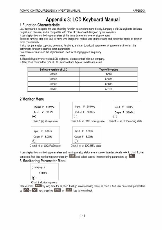
AC70 VC CONTROL FREQUENCY INVERTER MANUAL APPENDIX
141
Appendix 3: LCD Keyboard Manual1 Function CharacteristicLCD keyboard is designed for user checking function parameters more directly. Language of LCD keyboard includesEnglish and Chinese, and is compatible with other LED keyboard designed by our company.It can display two monitoring parameters at the same time when inverter stops or runs.States of running, stop and fault all have vivid image that makes user to understand and remember states of invertermore conveniently.It also has parameter copy and download functions, and can download parameters of same series inverter .It isconvenient for user to change batch parametersPotentiometer is also on the keyboard and used for changing given frequencyNote:1. If special type inverter needs LCD keyboard, please contact with our company.2. User must confirm that type of LCD keyboard and type of inverter are suited.
2 Monitor Menu
Input F 50.00Hz
Output F 50.00Hz
Chart 1 (a) at stop state Chart1 (b) at FWD running state Chart1 (c) at REV running state
Input F 5.00Hz
Output F 5.00Hz
Input F 5.00Hz
Output F 5.00Hz
Chart1 (d) at JOG FWD state Chart1 (e) at JOG REV state
It can display two monitoring parameters and running or stop status every state of inverter, details refer to chart 1.User
can select first -line monitoring parameters by ,and select second-line monitoring parameters by .
3 Monitoring Parameter Menu
Chart 2 Monitoring menuPlease press key long time for 1s, then it will go into monitoring menu as chart 2.And user can check parameters
by or key, pressing or key to return back.
Software version of LCD Type of inverters
KB10B AC70
KB30B AC80B
KB50B AC80C
KB70B AC100

AC70 VC CONTROL FREQUENCY INVERTER MANUAL APPENDIX
142
4 Parameters Menu(1) First level menu(Reserve)(2) Second level menu
Chart 3(a) Basic parameter Chart 3(b) External terminal Chart 3(c) Function parameter
The second level menu include 3 part: Basic parameter, External terminal, Function parameter, as show in chart 3.
Press key and enter into 3(a).User can select anyone of them by press or key. Press key
means selecting the item, And Press key to move monitoring interface, Basic parameter, External terminal,
Function parameter these 4 inverter face circular by turn.(3) Third level menu
Chart 4 (a) changing line Chart 4 (b) data Chart 4 (c) group
After going into second level menu, press key to go into third level menu. Third level menu includes three kinds,
changing line, data and group.
Changing line: First line displays second level items, second and third line display third level items, and position of
cursor is factory default setting, details refer to char t 4(a).
Press key to replace items,
Press or to move cursor,
Press to return back,
Press to select item, and then return back.
Data: First line displays second level menu items, and second line displays data ,details refer to chart 4(b)
Press to replace items,
Press or to increase or decrease data while pressing , Press or to increase or decrease
data from lowest bit without pressing ,
Press to return back.
Press to confirm modifying data, and then return back.
Group: First line displays second level menu items, second line displays group number, and third line displays third level
menu items, details refer to chart 4(c)
Press to change another group, Press or to change items,
Press key to return back.
Press to confirm modifying items, and then return back.
If pressing or cannot modify items in third level menu, and display ”Read only” all that reminder user of
parameter is no t allowed to modify or when inverter is running ,modifying is forbidden
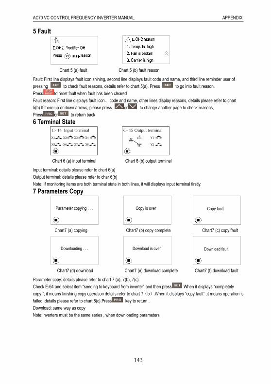
AC70 VC CONTROL FREQUENCY INVERTER MANUAL APPENDIX
143
5 Fault
Chart 5 (a) fault Chart 5 (b) fault reason
Fault: First line displays fault icon shining, second line displays fault code and name, and third line reminder user of
pressing to check fault reasons, details refer to chart 5(a). Press to go into fault reason.
Press to reset fault when fault has been cleared
Fault reason: First line displays fault icon、code and name, other lines display reasons, details please refer to chart
5(b).If there up or down arrows, please press or to change another page to check reasons,
Press or to return back
6 Terminal State C- 14 Input terminal
X1 X2 X3 X4
X5 X6 X7 X8
C- 15 Output terminal
Y2
Y1
Chart 6 (a) input terminal Chart 6 (b) output terminal
Input terminal: details please refer to chart 6(a)
Output terminal: details please refer to char 6(b)
Note: If monitoring items are both terminal state in both lines, it will displays input terminal firstly.
7 Parameters Copy
Parameter copying . . . Copy is over Copy fault
Chart7 (a) copying Chart7 (b) copy complete Chart7 (c) copy fault
Downloading . . . Download is over Download fault
Chart7 (d) download Chart7 (e) download complete Chart7 (f) download fault
Parameter copy: details please refer to chart 7 (a), 7(b), 7(c)
Check E-64 and select item “sending to keyboard from inverter”,and then press .When it displays “completely
copy ”, it means finishing copy operation details refer to chart 7(b).When it displays ”copy fault” ,it means operation is
failed, details please refer to chart 8(c).Press key to return .
Download: same way as copy
Note:Inverters must be the same series , when downloading parameters

AC70 VC CONTROL FREQUENCY INVERTER MANUAL APPENDIX
144
8 Self-tuning
Detect waiting Resting self-tuning
Chart 8 (a) waiting Chart 8 (b) resting type self-tuning
Rotary self-tuning Exciting detect
Chart 8 (c) rotary type self-tuning Chart 8(d) exciting magnetic detecting
Resting type self-tuning: steps as chart 8 (a), (b) and (d).Please set H-62=2, and press key to go into motor
detecting waiting menu, details refer to chart 8(a).Then press key, and it will display resting self-tuning, details
refer to 8(b), It displays “exciting detecting” when self-tuning is over, details refer to chart 9(d), then it will return back
automatically.
Rotary self-tuning: steps as chart 8 (a),(b)and (d). Please set F-62=1, and press key to go into motor detecting
waiting menu, details refer to chart 8(a).Then press key, and it will display resting self-tuning, details refer to 8(b),
while resting self-tuning is over, it displays rotary self-tuning, details refer to chart8(c), After rotary self-tuning over, it
displays exciting detecting, details refer to chart 8(d), then it will return back automatically.
9 Other Menus
0
Locked code
Voltage is low
Chart 9 (a) keyboard locked Chart 9 (b) low voltage Chart 9 (c) model of inverterKeyboard locked, as chart 9(a).Keyboard will display locked menu when going into next menu, after user setting
password and selecting parameter locked function. Please type correct password and then go into next menu.
Low voltage, as chart 9(b).When input voltage is low, it will display this warning.
Model of inverter, as chart 9(c).When power on, if communication is ok, it will display this menu, and if not, it will display
keyboard connection fault.