AADE-07-NTCE-31 Pushing the Envelope with Coil Tubing ...
17
Copyright 2007, AADE This paper was prepared for presentation at the 2007 AADE National Technical Conference and Exhibition held at the Wyndam Greenspoint Hotel, Houston, Texas, April 10-12, 2007. This conference was sponsored by the American Association of Drilling Engineers. The information presented in this paper does not reflect any position, claim or endorsement made or implied by the American Association of Drilling Engineers, their officers or members. Questions concerning the content of this paper should be directed to the individuals listed as author(s) of this work. Abstract Coil tubing drilling in the western Canadian sedimentary basin has revolutionized the shallow gas drilling market. Although coil tubing drilling has brought significant improvements to this area, there are limitations. These limitations include depth of penetration, vertical control in problematic deviation areas, and directional drilling. With increased pressure to reduce drilling cost, coil tubing drilling can be an economic advantage for both directional wells and drill depths over 1500m. With emerging advances in coil tubing drilling rig depth capacity, these typical shallow gas depths can be pushed past 1500m. Pushing coil tubing drill depths past 1500m has specific challenges with regard to directional control and directional drilling. For a large infield development well program, economic advantages can be achieved with coiled tubing drilling if the correct geological properties exist. Directional drilling with coil tubing is not a new technology, but has typically been limited in open hole size. When applying coil tubing drilling and rotary steerable technology, open hole advantages include an increase in hole size and a reduction in the overall tortuosity of the well bore. Development fields with both oil and gas wells require a larger open hole size for an effective completion program. This paper presents the challenges encountered in the project from the basic conceptual design, through the detailed engineering phase, to the execution of applying coil tubing drilling with rotary steerable technology for both directional drilling and directional control. The project objectives incorporate an overall decrease in rig operation days. The primary factors incorporated to achieve this are: mobilization, rig up and down operations, drilling while surveying, tool communication while drilling, and elimination of slide drilling. Introduction The western Canadian energy market has been subjected to an increasing cost environment. Maintaining a constant well cost or reducing well costs are a continual challenge. Coil Tubing Drilling (CTD) using Hybrid Rigs has been a major factor in controlling drilling costs for shallow oil and gas wells. ConocoPhillips has seen success with the CTD and embarked on a program to extend CTD deeper. The deeper CTD has the potential to reduce drilling costs in western Canada and learnings can be applied to other basins worldwide. The purpose of this paper is to conduct a detailed analysis and determine the success, failures, and key learnings from two, three-well CTD projects. Deviation control was deemed as the most significant issue with taking CTD deeper and extending into other basins. The first project involved proving directional drilling with coil tubing and rotary steerable BHA (RSS BHA). The second project involved coil tubing drilling past 2000m, utilizing learnings from the first project to control well deviation. Both projects utilized Hybrid Coil Tubing Drilling rigs. Pictures of the hybrid rigs used in this project are shown in figure 1, 2, and 3. Hybrid CTD rigs are effective for three main reasons in the basin: high penetration rate, quick mobilization, and rig up and rig down time. The western Canadian sedimentary basin is a relatively fast drilling environment. As the rate of penetration is increased, off bottom time will have a significant impact on a drilling program. The inherent advantage with CTD, in comparison to conventional drilling rigs, is that no time is required to make drill pipe connections. Off bottom time is defined as any time when drilling operations have stopped due to connection time or surveying when directional drilling. Figure 4 compares “Effective ROP” and “On Bottom ROP” when accounting for off bottom time. When drilling with a high rate of penetration, off bottom time will become a significant factor over the course of the well. For conventional drilling rigs, typical off bottom times can range from four to six minutes. In Figure 4, an on bottom ROP of 120 m/hr with connection time included would result in an effective ROP of 60 m/hr (assumed off bottom time for each connection at 5min). As the formation becomes harder and the rate of penetration drops, the CTD advantage is reduced. In Figure 4 for on bottom ROP of 50 m/hr, with connection time included, will result in an effective ROP of 35 m/hr (assumed off bottom time for each connection at 5min). In a directional application, where longer survey and connection time are prevalent, on AADE-07-NTCE-31 Pushing the Envelope with Coil Tubing Drilling C. L. Brillon, ConocoPhillips Canada; R. S. Shafer, ConocoPhillips Company and A. A. Bello, Schlumberger
-
Upload
khangminh22 -
Category
Documents
-
view
5 -
download
0
Transcript of AADE-07-NTCE-31 Pushing the Envelope with Coil Tubing ...

Copyright 2007, AADE This paper was prepared for presentation at the 2007 AADE National Technical Conference and Exhibition held at the Wyndam Greenspoint Hotel, Houston, Texas, April 10-12, 2007. This conference was sponsored by the American Association of Drilling Engineers. The information presented in this paper does not reflect any position, claim or endorsement made or implied by the American Association of Drilling Engineers, their officers or members. Questions concerning the content of this paper should be directed to the individuals listed as author(s) of this work.
Abstract
Coil tubing drilling in the western Canadian sedimentary basin has revolutionized the shallow gas drilling market. Although coil tubing drilling has brought significant improvements to this area, there are limitations. These limitations include depth of penetration, vertical control in problematic deviation areas, and directional drilling. With increased pressure to reduce drilling cost, coil tubing drilling can be an economic advantage for both directional wells and drill depths over 1500m.
With emerging advances in coil tubing drilling rig depth
capacity, these typical shallow gas depths can be pushed past 1500m. Pushing coil tubing drill depths past 1500m has specific challenges with regard to directional control and directional drilling. For a large infield development well program, economic advantages can be achieved with coiled tubing drilling if the correct geological properties exist.
Directional drilling with coil tubing is not a new technology, but has typically been limited in open hole size. When applying coil tubing drilling and rotary steerable technology, open hole advantages include an increase in hole size and a reduction in the overall tortuosity of the well bore. Development fields with both oil and gas wells require a larger open hole size for an effective completion program.
This paper presents the challenges encountered in the project from the basic conceptual design, through the detailed engineering phase, to the execution of applying coil tubing drilling with rotary steerable technology for both directional drilling and directional control. The project objectives incorporate an overall decrease in rig operation days. The primary factors incorporated to achieve this are: mobilization, rig up and down operations, drilling while surveying, tool communication while drilling, and elimination of slide drilling.
Introduction
The western Canadian energy market has been subjected to an increasing cost environment. Maintaining a constant well cost or reducing well costs are a continual challenge. Coil Tubing Drilling (CTD) using Hybrid Rigs has been a major factor in controlling drilling costs for shallow oil and gas
wells. ConocoPhillips has seen success with the CTD and embarked on a program to extend CTD deeper. The deeper CTD has the potential to reduce drilling costs in western Canada and learnings can be applied to other basins worldwide.
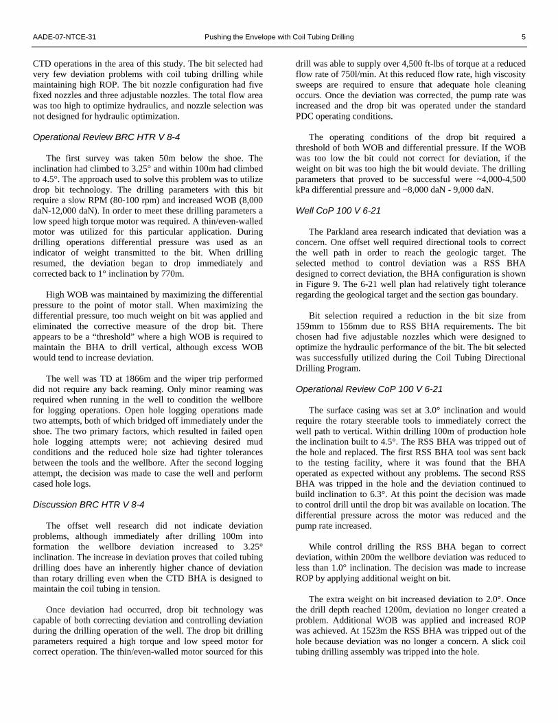
The purpose of this paper is to conduct a detailed analysis and determine the success, failures, and key learnings from two, three-well CTD projects. Deviation control was deemed as the most significant issue with taking CTD deeper and extending into other basins. The first project involved proving directional drilling with coil tubing and rotary steerable BHA (RSS BHA). The second project involved coil tubing drilling past 2000m, utilizing learnings from the first project to control well deviation. Both projects utilized Hybrid Coil Tubing Drilling rigs. Pictures of the hybrid rigs used in this project are shown in figure 1, 2, and 3.
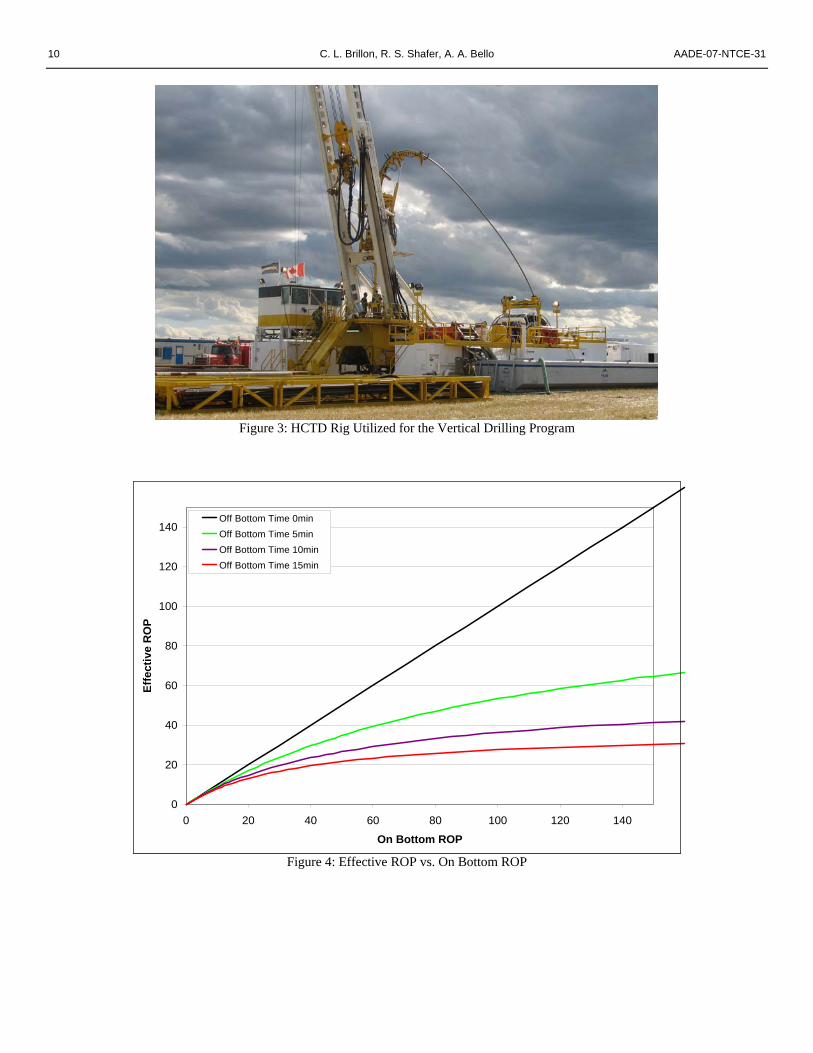
Hybrid CTD rigs are effective for three main reasons in the basin: high penetration rate, quick mobilization, and rig up and rig down time. The western Canadian sedimentary basin is a relatively fast drilling environment. As the rate of penetration is increased, off bottom time will have a significant impact on a drilling program. The inherent advantage with CTD, in comparison to conventional drilling rigs, is that no time is required to make drill pipe connections. Off bottom time is defined as any time when drilling operations have stopped due to connection time or surveying when directional drilling. Figure 4 compares “Effective ROP” and “On Bottom ROP” when accounting for off bottom time.
When drilling with a high rate of penetration, off bottom
time will become a significant factor over the course of the well. For conventional drilling rigs, typical off bottom times can range from four to six minutes. In Figure 4, an on bottom ROP of 120 m/hr with connection time included would result in an effective ROP of 60 m/hr (assumed off bottom time for each connection at 5min).
As the formation becomes harder and the rate of
penetration drops, the CTD advantage is reduced. In Figure 4 for on bottom ROP of 50 m/hr, with connection time included, will result in an effective ROP of 35 m/hr (assumed off bottom time for each connection at 5min). In a directional application, where longer survey and connection time are prevalent, on
AADE-07-NTCE-31
Pushing the Envelope with Coil Tubing Drilling C. L. Brillon, ConocoPhillips Canada; R. S. Shafer, ConocoPhillips Company and A. A. Bello, Schlumberger

2 C. L. Brillon, R. S. Shafer, A. A. Bello AADE-07-NTCE-31
bottom ROP of 50 m/hr with connection time and survey time included will result in a effective ROP of 27 m/hr (assumed off bottom time for each connection at 10 min). When drilling in harder rock, the CTD develops an additional advantage in a direction drilling application if surveying while drilling is accomplished.
Another factor that requires consideration is that CTD
ROP will be proportional to the RPM of the bit. In a hard rock drilling environment with a downhole motor, a conventional rotary drilling rig will have a surface rotation advantage. The additional surface rotation will ultimately generate a higher ROP for a conventional rotary drilling when compared to a CTD rig.
The diagram in Figure 5 shows a direct comparison
between a coil tubing rig and a conventional drilling rig. As illustrated by Figure 5, a significant improvement can be achieved by the elimination of connection time. Another significant advantage of coil tubing is that connections are eliminated during trips. Pumping during wiper trips will eliminate any swabbing affect that could pose a potential problem.
Another factor that makes Hybrid Coil Tubing Drilling
(HCTD) rigs effective is cutting cost by reducing mobilization time and rig up time. HCTD rigs are designed to decrease rig up time and reduce manual labor. It is common for a HCTD rig to drill two shallow gas wells per day during summertime operations.
In general, the HCTD has a positive impact on HSE. The
design changes have incorporated many automated features reducing personal contact with equipment and creating both a quicker and safer work environment. Another factor that improves the work environment is the elimination of connections and rotating equipment on the rig floor during drilling or tripping operations.
Disadvantages associated with HCTD rigs are the size and
weight of the drilling carrier. A typical configuration of a HCTD rig will have the mast and coil tubing mounted on a single carrier, which could create weights in excess of 90,000kg. In many cases road restrictions will require the coil tubing reel to be removed for rig moves. Drilling contractor rig designs vary, and one particular design does incorporate a separated mast and coiled tubing unit as separate rig loads. The disadvantage to this design is the additional time required to switch from conventional drilling to coil tubing drilling mode.
Another disadvantage associated to CTD is the restriction
on pipe rotation. The problems associated with restricted pipe rotation will typically be a factor during directional drilling applications, where pipe drag becomes an issue, or in stuck pipe situations.
Coil Tubing Directional Drilling BHA Selection
The most significant issue in drilling deeper with coil is
directional control, which are required in a significant number of deeper wells.
Directional drilling with coiled tubing is not a new
technology; however, a significant number of limitations exist with the current coiled tubing directional BHA’s that are available in today’s market. A major limitation to directional drilling with coiled tubing is the size of open hole that can be drilled, typically limited to less than 159mm. Open hole size limitation is typically a function of the coil tubing size and the size of the orientation tool required to control the direction of the bent motor assembly.
Various directional drilling methods were reviewed for this
drilling project. Rotary steerable was chosen as the method with the most long-term potential to extend coil tubing deeper and reduce drilling times. The reasons for this decision were:
• Tool communication and directional survey while
drilling • Equipment availability for hole sizes 159mm and
larger • Standard convention drilling BHA, increased
availability and reliability • No off bottom time required to orient tool, compared
to ratchet type orienter • No difficulties in orienting BHA due to hole drag • No complicated surface system to control wireline
orienter • Reduction in hole tortuosity, elimination of slide
drilling • Improved ROP by maintaining full WOB
The RSS BHA used is simpler to operate than other
systems. The tool uses mud actuated pads to deviate the direction of drilling by pushing against the formation. Operationally, the tool can be run either as a stand alone or in combination with MWD/LWD tools with real time communications to the surface.
Communication with the tool is achieved by lowering and
raising the mud flow rate to specific values for specific time periods in a defined sequence. These coded pulses are detected by the tool and the new steering setting is activated. RSS BHA The feature of downlink at any time telemetry allows the user to change the settings of the tool while it is downhole, without cycling the pumps.
During this communication sequence, which may require
up to 15 min, the rotary steerable will be in neutral mode. Therefore, control drilling may be required until the survey confirms the reception of the order. This communication

AADE-07-NTCE-31 Pushing the Envelope with Coil Tubing Drilling 3
sequence virtually eliminates off bottom time. Overall, the RSS BHA increases ROP because there is no
downtime to take surveys or communicate with the tool. The HCTD drilling does not make connections, which also contributes to a major elimination of off bottom time.
The RSS BHA on coil uses the same equipment as
conventional drilling so research and design for conventional drilling equipment can be applied to CTD. Therefore, any conventional directional drilling assembly that can be used in a coiled tubing direction drilling application will have a significant advantage. Part 1: Coil Tubing Directional Drilling Program
Engineering and Well Planning
The field subject to this study is a typical sweet shallow
gas field found in the western Canadian sedimentary basin. These wells target the Belly River formation and vary from 650-800mTVD. Complex surface locations will typically dictate whether the hydrocarbon target can be reached with a vertical well or if a directional well is required.
A typical directional well profile is designed as a simple
build and hold, as shown in figure 6. The targeted formation is relatively shallow and does not allow for more complex directional paths such as an “S” shape, resulting in the formation intersected at a high inclination. The directional parameters are limited to 5°/30m DLS to a maximum inclination of 45°. If these directional limits are exceeded, the time required to drill the well and potential hole problems decrease well economics.
A pre-job risk assessment was conducted in order to
review offset problems on the area, anticipate issues during the operation, and prepare an action plan to mitigate those issues. A complete risk assessment summary can be found on the Table 1 over the appendix section.
The relatively low production rates for these wells do not
require complex completions resulting in a simple drilling program. The 177.8mm surface casing will be set at ~100m where 156mm will be drilled to a depth of ~800m, and 114.3mm casing will be run in hole and cemented. Typically these wells require only cased hole logs, as the production from these wells are gas and do not have a water contact zone.
The well depths and casing requirements for these wells
are within the limitations of the HCTD rigs available in the western Canadian market. The drilling rig chosen for this drilling application is capable of 1500m of 88.9mm coiled tubing and 1200m of 88.9mm jointed pipe. This rig also has a fully automated pipe arm and pipe handling systems. The mud pump available on this rig has the capability to pump against high pressure associated with the coil tubing reel and the
directional drilling assembly. In addition to the drilling advantages, the rig weight loads were reduced because the coil tubing unit was separated from the mast and carrier. A photo of the HCTD rig is shown in Figure 1 and 2.
The directional drilling BHA required 120.6mm BHA to
drill 156mm open hole. The selected RSS BHA was capable of having a mud motor separating the rotary steerable tool from the directional survey equipment. The RSS BHA schematic is shown in figure 7. The directional survey equipment would also require automatic surveys sent to surface to achieve survey while drilling. One disadvantage of this configuration is the absence of real time connection with the tool, to be able to verify the receptions of orders or downlinks.
Combining RSS directional drilling assembly and coiled
tubing has the potential to decrease drilling time and ultimately reduce the overall drill cost per well. There was no guaranteed success for the project, because coiled tubing and RSS directional drilling had not been successfully deployed before. The previous experience with this BHA configuration involved many successful drilling runs on conventional jointed pipe applications.
The objectives for the drilling program are as follows: • Obtain accurate directional surveys while drilling. • Establish tool communication during drilling operations. • Directional assembly capable of producing 5.0°/30m
Coil Tubing Directional Drilling Program Review
CoP 100 DD 10-1
The directional profile was designed with a 2.0°/30m build rate until an inclination of 20° where the tangent section would reach the hydrocarbon target at a MD of 740m.
The RSS BHA successfully function tested on surface and
ran in hole. When the kick off point was reached, directional inclination could not be achieved. The RSS BHA was tripped out of the hole and the well was drilled with a conventional directional jointed pipe drilling assembly.
Data transfer was made from the RSS BHA and
determined that the BHA did not accept any attempt for directional communication. The problem was determined to be incorrect pump liner sizing, which resulted in an incorrect flow rate for tool communication and caused the failure in communication.
CoP et at 102 DD 16-25
The second well in the project was designed with a directional profile similar to the first well. Once the liner size problem was found and correct flow through the BHA was achieved for communication, the RSS BHA was capable of

4 C. L. Brillon, R. S. Shafer, A. A. Bello AADE-07-NTCE-31
producing build rates of 6-7°/30m, which were above the required build rates for the directional design. The well was successfully drilled to TD.
CoP et al 100 DD 2-33
The final well of the project required a slightly more
aggressive build section 5.0°/30 m to an inclination of 43°. The learnings from the first well indicate that both communication downlinks and surveys can be successfully made during drilling operations. The attempts for this well was to increase the rate of penetration by drilling with high differential pressure across the motor and with a better knowledge of the RSS BHA build tendencies throughout the formations encountered.
The RSS BHA could not achieve an increase in inclination
at the kick off point. When the RSS BHA was inspected on surface, the pads required for directional control were found to be very tight potentially indicating that failure had occurred during the run. The final well was directionally drilled with a conventional directional jointed pipe drilling assembly. Coil Tubing Directional Drilling Program Discussion
The result was that only one of the three wells were drilled utilizing coil tubing, and the remaining two were drilled using conventional directional drilling equipment. The successful well drilled with coiled tubing met all objectives set out in the initial stages of the program. This test proved RSS BHA can be successfully used on coil to drill shallow directional wells. It also illustrated the improvement in drilling time for both CTD and RSS.
In the previous discussion, including figure 4, HCTD rigs
can offer a significant advantage over drilling with a conventional drilling rig. Figure 6 illustrates the time required to drill out of surface casing to the total depth of the well. All three wells were drilled maintaining constant drilling parameters (mud, rig, bit motor speed, etc.). The only significant difference is that the first well was vertical, to show a relative comparison to directional drilling time requirements.
As shown in figure 6, the coil tubing directional drilling
time curve can be significantly improved over conventional directional drilling by approximately 30%. Another comparison that can be made is coil tubing directional drilling and coil tubing vertical drilling. As illustrated in figure 6, the coil tubing directionally drilled well has a similar time curve. Optimizing drilling parameters for the RSS BHA could further decrease directional drilling curves similar to vertical wells drilled with coiled tubing. Part 2: Drilling Deep Vertical with Coil Tubing Engineering and Well Planning
The rig selection was based on matching the rig capabilities with the drilling requirements. The drilling contractor and rig specifications chosen had the advantage of 88.9mm coil tubing, which offered favorable internal and external hydraulics and increased coil tubing force capacities when drilling 159mm or 200mm open hole sizes. The rig depth capacity was 2200m with either 88.9mm coil tubing or 101.6mm jointed pipe. The mud pump available on this rig has the capability to pump against high pressure associated with the coil tubing reel and the directional control drilling assembly.
The BHA design was to deploy enough drill collars to
ensure that the coil tubing was always in tension and the weight applied to the bit was only supplied from the drill collars. Another challenge was designing a BHA that would minimize or correct for deviation, if encountered, during drilling operations. Two possible solutions where chosen: implement the use of drop bit technology or the use of RSS BHA tools to correct for deviation.
Drop bit technology has been used successfully on
conventional rigs drilling 200 mm open hole size, although there was no offset data regarding the success of the 159mm open hole size and limited offset research with a coil tubing application. The directional control BHA is similar to the BHA configuration used during the trials in July 2006. The success of the Coil Tubing Directional Drilling Program proved the RSS technology’s application for a coiled tubing drilling program.
Offset drilling records indicated that previous mud systems
have been a standard gelled chemical system. For the initial coil tubing project the plan was to utilize a polymer mud system which offered additional formation inhibition, over a traditional gelled chemical mud system. The additional inhibition, along with eliminating the flocculated water section, would better protect the formation from fluid invasion and increase the probability of success during open hole logging operations.
The objectives for the Vertical Project were set as follows: • Establish successful coil tubing drill depth past 1500m • Provide effective deviation control • Decrease overall drilling time
Well BRC HTR V 8-4
Detailed offset well drilling records for wells within 1.5km
of the proposed well were available. The drilling records did not indicate deviation problems; however these wells were drilled with slick drilling assemblies utilizing tri-cone insert bits so no deviation problems were expected. If deviation did prove to be a concern, the drop bit technology or a RSS vertical control BHA would be a contingency plan.
Bit selection was chosen based on past experience with
AADE-07-NTCE-31 Pushing the Envelope with Coil Tubing Drilling 5
CTD operations in the area of this study. The bit selected had very few deviation problems with coil tubing drilling while maintaining high ROP. The bit nozzle configuration had five fixed nozzles and three adjustable nozzles. The total flow area was too high to optimize hydraulics, and nozzle selection was not designed for hydraulic optimization.
Operational Review BRC HTR V 8-4
The first survey was taken 50m below the shoe. The inclination had climbed to 3.25° and within 100m had climbed to 4.5°. The approach used to solve this problem was to utilize drop bit technology. The drilling parameters with this bit require a slow RPM (80-100 rpm) and increased WOB (8,000 daN-12,000 daN). In order to meet these drilling parameters a low speed high torque motor was required. A thin/even-walled motor was utilized for this particular application. During drilling operations differential pressure was used as an indicator of weight transmitted to the bit. When drilling resumed, the deviation began to drop immediately and corrected back to 1° inclination by 770m.
High WOB was maintained by maximizing the differential pressure to the point of motor stall. When maximizing the differential pressure, too much weight on bit was applied and eliminated the corrective measure of the drop bit. There appears to be a “threshold” where a high WOB is required to maintain the BHA to drill vertical, although excess WOB would tend to increase deviation.
The well was TD at 1866m and the wiper trip performed did not require any back reaming. Only minor reaming was required when running in the well to condition the wellbore for logging operations. Open hole logging operations made two attempts, both of which bridged off immediately under the shoe. The two primary factors, which resulted in failed open hole logging attempts were; not achieving desired mud conditions and the reduced hole size had tighter tolerances between the tools and the wellbore. After the second logging attempt, the decision was made to case the well and perform cased hole logs.
Discussion BRC HTR V 8-4
The offset well research did not indicate deviation
problems, although immediately after drilling 100m into formation the wellbore deviation increased to 3.25° inclination. The increase in deviation proves that coiled tubing drilling does have an inherently higher chance of deviation than rotary drilling even when the CTD BHA is designed to maintain the coil tubing in tension.
Once deviation had occurred, drop bit technology was capable of both correcting deviation and controlling deviation during the drilling operation of the well. The drop bit drilling parameters required a high torque and low speed motor for correct operation. The thin/even-walled motor sourced for this
drill was able to supply over 4,500 ft-lbs of torque at a reduced flow rate of 750l/min. At this reduced flow rate, high viscosity sweeps are required to ensure that adequate hole cleaning occurs. Once the deviation was corrected, the pump rate was increased and the drop bit was operated under the standard PDC operating conditions.
The operating conditions of the drop bit required a threshold of both WOB and differential pressure. If the WOB was too low the bit could not correct for deviation, if the weight on bit was too high the bit would deviate. The drilling parameters that proved to be successful were ~4,000-4,500 kPa differential pressure and ~8,000 daN - 9,000 daN.
Well CoP 100 V 6-21
The Parkland area research indicated that deviation was a concern. One offset well required directional tools to correct the well path in order to reach the geologic target. The selected method to control deviation was a RSS BHA designed to correct deviation, the BHA configuration is shown in Figure 9. The 6-21 well plan had relatively tight tolerance regarding the geological target and the section gas boundary.
Bit selection required a reduction in the bit size from
159mm to 156mm due to RSS BHA requirements. The bit chosen had five adjustable nozzles which were designed to optimize the hydraulic performance of the bit. The bit selected was successfully utilized during the Coil Tubing Directional Drilling Program.
Operational Review CoP 100 V 6-21
The surface casing was set at 3.0° inclination and would
require the rotary steerable tools to immediately correct the well path to vertical. Within drilling 100m of production hole the inclination built to 4.5°. The RSS BHA was tripped out of the hole and replaced. The first RSS BHA tool was sent back to the testing facility, where it was found that the BHA operated as expected without any problems. The second RSS BHA was tripped in the hole and the deviation continued to build inclination to 6.3°. At this point the decision was made to control drill until the drop bit was available on location. The differential pressure across the motor was reduced and the pump rate increased.
While control drilling the RSS BHA began to correct deviation, within 200m the wellbore deviation was reduced to less than 1.0° inclination. The decision was made to increase ROP by applying additional weight on bit.
The extra weight on bit increased deviation to 2.0°. Once
the drill depth reached 1200m, deviation no longer created a problem. Additional WOB was applied and increased ROP was achieved. At 1523m the RSS BHA was tripped out of the hole because deviation was no longer a concern. A slick coil tubing drilling assembly was tripped into the hole.

6 C. L. Brillon, R. S. Shafer, A. A. Bello AADE-07-NTCE-31
When tripping out of the hole, reaming operations were required from 1100m to surface. When tripping in the hole, slight ream was required from 500-1100 m. Deviation began to increase; at 1982m the deviation was 4.5° and the well was TD at 2071m and 5.0° inclination.
The wiper trips for the logging operation did not require any significant reaming. Logging operations bridged twice, once at 277m and at 321m. The third logging attempt utilized tubing conveyed logs. The logging tools reached bottom without any problems, although the tools did not deploy out of the tubing and all measurements were rendered useless. The tool failure was reported as the first of its kind. At this point casing was run and cased hole logs were supplied to the team. Discussion CoP 100 V 6-21
Under standard drilling parameters the reaction of the RSS
BHA increased the deviation of the well bore. To decrease deviation, reduced weight on bit was required until 1200m was reached. The BHA was further examined and appeared to have a configuration which created a natural tendency to build inclination. With increased WOB this correction could not overcome the natural tendency of the BHA to build angle.
The directional RSS BHA was tripped out hole and a slick
BHA was tripped in to finish the remaining section of the wellbore from 1550-2050m. When the drilling assembly was past 1850m, the wellbore began to deviate and the production casing was landed at 4.5° inclination. The result indicates that the 120.6mm drill collars are still “flexible” enough to allow wellbore deviation.
During tripping operations, tripping out the directional
assembly required additional time due to back reaming out of the hole. Once the slick drilling assembly was tripped in hole only slight reaming was required both in and out hole.
Wireline logging operations bridged twice, requiring two
clean out trips. The clean out trips were not successful; the solution to this problem was to run tubing conveyed logs. These logs were considered, although reduced log quality would result and the asset team would only consider tubing conveyed logs as a contingency. The first time these logs were run the tools did not deploy and cased hole logs were employed.
Well CoP 100 V 9-21
The engineering and programming of this well was very
similar in design to the CoP 100 V 6-21. The only difference was the final formation targeted the Turner Valley. Typically offset wells do not penetrate the Turner Valley, and current detailed offset data for drilling performance was not available.
The associated drilling problem for this limestone
formation is the compressive strength of the rock. This
compressive strength would require at least one bit run and the use of tri-cone diamond insert bits. Recommendations from bit supply companies were not conclusive whether the Turner Valley formation was drillable with PDC bit technology. In the likely event that a PDC bit could not drill the Turner Valley, a bit trip was programmed at ~2000m to change for a tri-cone diamond insert bit. Operational Review CoP 100 V 9-21
The wellbore geometry along with the casing scheme was changed for this well. The change was made to mirror the drilling wellbore geometry that proved successful for logging operations with the conventional drilling rigs operated in the area. The production hole size was increased to 200mm which required a 171.5mm rotary steerable BHA size. The BHA configuration was changed and an additional stabilizer was added, as shown in figure 10. The stabilizer was added in an attempt to increase the rigidity of the RSS BHA. The drilling assembly was run in the well and built to an inclination of 4.4° in 80 m. The RSS BHA was pulled out of the hole and two stabilizers were removed from the BHA, as shown in figure 11. The BHA was tripped in hole and it immediately began to drop inclination and successfully maintained deviation below 1° inclination.
When drilling reached 1780m, the decision was made to trip the directional control BHA out hole and continue drilling with a slick BHA. Hole problems occurred during drilling operations which required two additional bit trips. Offset well information did not encounter similar problems.
When the Turner Valley formation was encountered the PDC could not drill into the formation and a bit trip was made. When the PDC bit was inspected on surface, severe damage to the cutting structure was observed. The tri-cone bit selected to drill into the Turner Valley, drilled 63m in 24hrs and was tripped to surface because of a reduction in ROP. The bit was inspected on surface and had severe damage and wear. At a depth of 2140m the well was called TD.
While logging out hole the caliper arms had to be closed several times to get through collapsed sections of the wellbore. At 706m the caliper arms mechanically failed and would not retract, resulting in stuck logging tool. The tools were successfully retrieved out of the wellbore with a side entry sub and fishing equipment. The casing was run and cemented without incident. Discussion CoP 100 V 9-21
Drilling 200mm open hole size had a significant reduction in ROP when compared to 156mm. Such a dramatic drop of ROP has not previously been experienced with coiled tubing drilling in other areas. The mud system was also changed from a Polymer to a Gel-Chem system. The previous two wells did not have conclusive evidence that the Polymer Mud system

AADE-07-NTCE-31 Pushing the Envelope with Coil Tubing Drilling 7
was an advantage, and the conventional drilling rigs have had good success with a Gel-Chem system. Drilling operations had encountered more problems during 9-21 when compared to the previous two wells. The decision to change the mud system had decreased the drilling performance.
A significant difference that was noticed between the 6-21
well and the 9-21 well was increased stalling during drilling operations. In addition to increased hole size, a significant difference between the two wells was an increase in cutter size from 13mm to 16 mm. In comparison between coil tubing drilling and conventional rotary drilling, these pressure spikes are not typically seen during rotary drilling operations. Thin/even walled motors were not available for the 158.7 mm size and extended power sections were utilized.
A vertical control drilling assembly, which had previous
problems, had a couple of BHA design changes which were capable of controlling deviation in a problematic area as a direct result of the design changes. The success of vertical rotary steerable BHA has indicated that a correct RSS BHA configuration has been proven for the 171.5mm BHA size.
Open hole logs were successfully deployed to TD. Due to
a mechanical failure of the retracting caliper arms, the logging tools became stuck at 700m. Fishing operations were required to retrieve the wireline logging tools from the wellbore. For successful open hole logging operations in a geological problematic area, 200mm open hole is required.
The overall vertical project met two of the three objects set
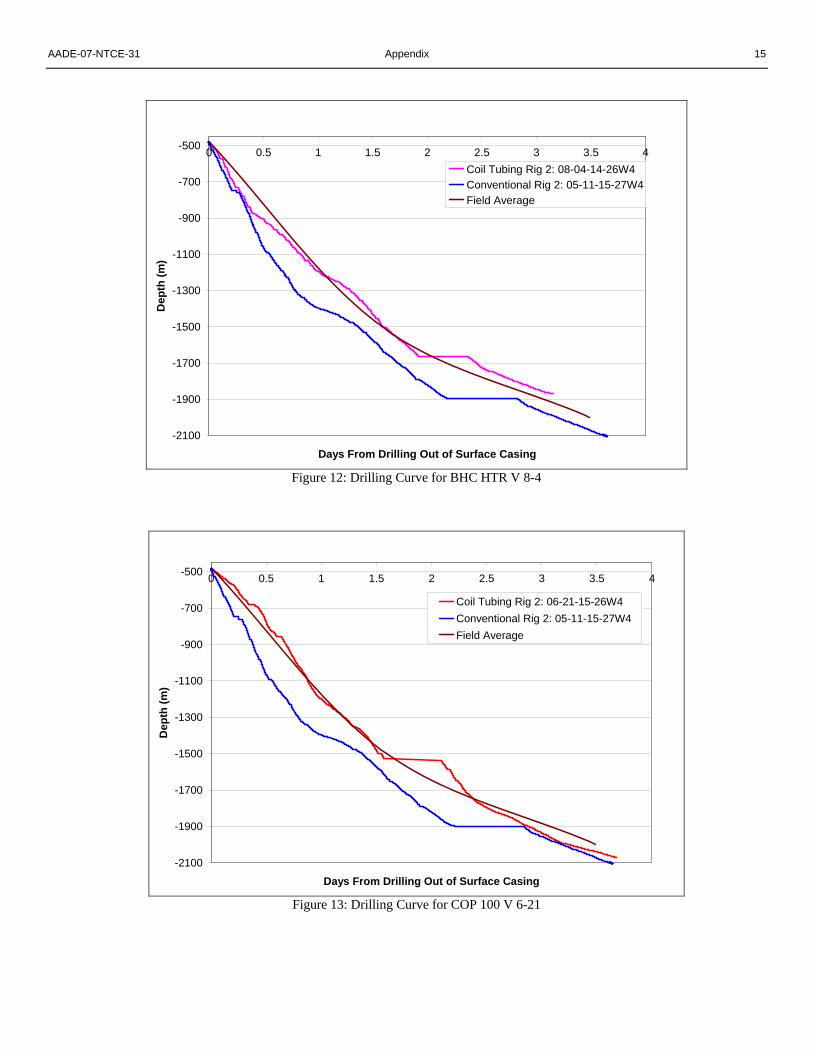
out at the beginning of the project. The drilling operations were successful to all three well depths. From the results, optimizations can be made for future projects. The graphs in Figure 12, 13, and 14 show a representation of drilling of production hole as compared to a field best, field average, and the individual well drill curve. For the 8-4 and 6-21 the drill curves met the field average. The 9-21 well had 81 hours of downtime due to problematic geological conditions, resulting in the longest drill time.
A Verticality correlation graph that includes all the wells
can be found in the Appendix under figure 15.
Conclusions
Coil tubing drilling has proven advantageous in high ROP environments. This advantage begins to decrease in vertical applications as harder rock environments are encountered and ROP begins to decrease. In directional drilling applications a significant advantage can be achieved even in hard rock applications if surveying while drilling can be achieved.
Coil tubing is inherently prone to deviation issues and can
be successfully controlled with the application of drop bit technology or an RSS vertical control drilling assembly. The disadvantage with drop bit technology is reduced ROP when
compared to a standard PDC design. Additional field testing and BHA refinement are required for a vertical control RSS BHA configuration. Motor section for any coil tubing drilling application should apply the use of thin/even-walled high torque motors, as stalling is more prevalent with coil tubing drilling than rotary drilling applications.
Bit selection for coil tubing drilling is fundamental, as an
aggressive PDC bit that historically worked well with rotary drilling applications would be too aggressive for coiled tubing drilling applications. Proper PDC bit selections for a CTD program should, at minimum, include a reduction of cutter size and potential increase of the PDC blade count. Coil tubing inherently has less wear and damage on PDC bits than conventional rotary drilling applications, so control drilling through formation change is not required.
Upgrading the water based mud system from a Gel-Chem
to a Polymer Mud system can mitigate the problematic geological properties encountered during the drilling project. In any coil drilling application, an upgraded mud system should be reviewed when drilling in problematic geological areas.
Coil Tubing Drilling had been a revolutionary tool to
shallow gas drilling in the western Canadian sedimentary basin. The drilling market that has embraced this technology has been development field drilling with know reserves, rock geomechanics and has proved easily drillable with conventional drilling methods. The two projects discussed in this paper indicate that coil tubing directional drilling can reduce overall drill time compared to conventional directional drilling to depths to 800m and coil tubing drilling can successfully drill to depths of 2000m. The natural progression for development field drill will be to merge both coil tubing drilling and rotary steerable directional technology to expand to development gas field to drill depths of 2000m.
Acknowledgments
The authors of this paper would like to thank the drilling contractor and field personal for their time and dedication during drilling operations. We would also like to thank ConocoPhillips & Schlumberger office staff for their continued support throughout both challenging projects. Nomenclature CTD = Coil Tubing Drilling RRS = Rotary Steerable Systems BHA = Bottomhole Assembly HCTD = Hybrid Coil Tubing Drilling MWD = Measurements While Drilling ROP = Rate of Penetration RPM = Revolutions Per Minute DLS = Dog Leg Severity WOB = Weight On Bit

8 C. L. Brillon, R. S. Shafer, A. A. Bello AADE-07-NTCE-31
References
1.Shafer, R.S.: “Step Change in Remote Exploration,” SPE/IADC 105051, SPE/IADC Drilling Conference, Amsterdam, The Netherlands, February 20-22, 2007.
2.Bourgoyne A.T., Chenevert M.E., Millheim K.K., Young F.S.: Applied Drilling Engineering.: SPE Testbook Series Vol.2, Society of Petroleum Engineers, Ninth Printing 2003.
3.Steve Devereux: Practical Well Planning, PenWell Publishing Company, 1998, ISBN 0-87814-696-2.
4.Gilles Gabolde, Jean-Paul Nguyen, Drilling Data Handbook, Eight Edition, Editions Technip, 2006.
5.C. Pratten, Rotary Steerable Systems in the Gulf of Mexico - A Step Change in Drilling Performance, AADE 01-NC-HO-22, AADE 2001 National Drilling Conference, Houston, Texas, March 27 - 29, 2001.
6.F. J. Schuh, P. Herbert, J. Harrell, The New Generation of Rotary Systems May be Closer Than You Think, AADE-03-NTCE-02, AADE 2003 National Drilling Conference and Exhibition, Houston, Texas, April 1-3, 2003.
7.C. Sidwell, J. Jares, M. Durant, Rotary Steerable in 6” hole Key to
Economic Wellbores, AADE-03-NTCE-03, AADE 2003 National Drilling Conference and Exhibition, Houston, Texas, April 1-3, 2003.
8.C. Lenamond, L. Marques, M. Anderson, S. Mota, Performance Gains for Rotary Steerable Through Specialized Bit Design, AADE-05-NTCE-46, AADE 2005 National Drilling Conference and Exhibition, Houston, Texas, April 5-7, 2005.
SI Metric Conversion Factors
in x 2.54* E+00 = cm ft x 3.048* E+01 = m lbf x 4.4482222 E+00 = N lbm x 4.535924 E+01 = Kg psi x 6.894757 E+00 = kPa
*conversion factor is exact

AADE-07-NTCE-31 Appendix 9
Appendix
Figure 1: HCTD Rig Utilized for the Directional Drilling Program
Figure 2: Hybrid Rig Transition from Conventional Drilling to Coil Drilling
10 C. L. Brillon, R. S. Shafer, A. A. Bello AADE-07-NTCE-31
Figure 3: HCTD Rig Utilized for the Vertical Drilling Program
0
20
40
60
80
100
120
140
0 20 40 60 80 100 120 140
On Bottom ROP
Effe
ctiv
e R
OP
Off Bottom Time 0minOff Bottom Time 5minOff Bottom Time 10minOff Bottom Time 15min
Figure 4: Effective ROP vs. On Bottom ROP

AADE-07-NTCE-31 Appendix 11
-1200
-1000
-800
-600
-400
-200
00 0.5 1 1.5 2
Days From Spud
Dep
th (m
)
Conventional Rig 1: 10-18-34-25Conventional Rig 1: 1-6-36-25Coil Tubing Rig 1: 7-22-35-26Coil Tubing Rig 2: 6-27-35-26
Figure 5: Coil Tubing vs. Conventional Drilling
-750
-650
-550
-450
-350
-250
-150
-500 0.1 0.2 0.3 0.4 0.5 0.6 0.7 0.8
Days from Drill out of Surface Casing
Dep
th (m
)
CoP 100 DD 10-1 (Conventional Directional)CoP et al 102 DD 16-25 (Coil Tubing Directional)CoP 100 V 1-30 (Vertical)
Figure 6: Coil Tubing vs. Conventional Directional Drilling

12 C. L. Brillon, R. S. Shafer, A. A. Bello AADE-07-NTCE-31
0
50
100
150
200
250
300
350
400
450
500
550
600
650
700
750
-100 -50 0 50 100 150 200 250 300 350 Vertical Section (m) Azim = 332.86°, Scale = 1(cm):50(m) Origin = 0 N/-S, 0 E/-W
TVD
Sca
le =
1(c
m):5
0(m
)
Tie-In
Surface Casing (177.8mm)KOP DLS 2.0°/30m
Tangent Section 13.23°
Belly River
Taber Coal
McKay Coal
Lea ParkProposed TD
Casing at 86 m
Projection to TDBasal Belly River
Critical Points
Critical Point MD INCL AZIM TVD VSEC N(+) / S(-) E(+) / W(-) DLS
Casing at 86 m 86.00 1.20 270.00 86.00 -0.16 -0.23 -0.10 1.49
Projection to TD 738.00 16.00 321.00 720.58 128.06 109.76 -66.61 0.67
True North
Tot Corr (M->T +15.7660°)
Mag Dec (+15.766°)
Grid Conv ()
True
Grid
Mag
-20
0
20
40
60
80
100
120
-100 -80 -60 -40 -20 0 20 40 60<<< W Scale = 1(cm):20(m) E >>>
<<<
S
Scal
e =
1(cm
):20(
m)
N >
>>
Surface Casing (177.8mm)
KOP DLS 2.0°/30m
Tangent Section 13.23°
Basal Belly River
Proposed TD
Casing at 86 m
Projection to TD
Figure 7: Directional Plan & Actual for COP DD 16

AADE-07-NTCE-31 Appendix 13
Figure 8: RSS/BHA Schematic
Figure 9: Vertical Control BHA Schematic for COP 100 V 6-21

14 C. L. Brillon, R. S. Shafer, A. A. Bello AADE-07-NTCE-31
Figure 10: Vertical Control BHA Design 1 for COP 100 V 9-21
Figure 11: Vertical Control BHA Design 2 for COP 100 V 9-21
AADE-07-NTCE-31 Appendix 15
-2100
-1900
-1700
-1500
-1300
-1100
-900
-700
-500 0 0.5 1 1.5 2 2.5 3 3.5 4
Days From Drilling Out of Surface Casing
Dep
th (m
)Coil Tubing Rig 2: 08-04-14-26W4Conventional Rig 2: 05-11-15-27W4Field Average
Figure 12: Drilling Curve for BHC HTR V 8-4
-2100
-1900
-1700
-1500
-1300
-1100
-900
-700
-500 0 0.5 1 1.5 2 2.5 3 3.5 4
Days From Drilling Out of Surface Casing
Dep
th (m
)
Coil Tubing Rig 2: 06-21-15-26W4Conventional Rig 2: 05-11-15-27W4Field Average
Figure 13: Drilling Curve for COP 100 V 6-21

16 C. L. Brillon, R. S. Shafer, A. A. Bello AADE-07-NTCE-31
-2100
-1900
-1700
-1500
-1300
-1100
-900
-700
-500 0 0.5 1 1.5 2 2.5 3 3.5 4
Days From Drilling Out of Surface Casing
Dep
th (m
)
Coil Tubing Rig 2: 09-21-15-26W4Conventional Rig 2: 05-11-15-27W4Field Average
Figure 14: Drilling Curve for COP 100 V 9-21

AADE-07-NTCE-31 Appendix 17
0
250
500
750
1000
1250
1500
1750
2000
2250-50 0 50 100 150 200
ROP (m/h)
0
250
500
750
1000
1250
1500
1750
2000
22500 1 2 3 4 5 6 7
Inclination (Deg)
TVD
(m)
CoP 100 V 6-21CoP 100 V 9-21BRC HTR 8-4
Zone of High Build Tendency
Good Run RSS
End of RSS Run
Form. 2
Form. 3
Form. 4
Form. 5
Form. 1
Surface Casing
Figure 15: Verticality Correlation