A Virtual Factory for Smart City Service Integration
195
Universidade do Minho MAP-i Doctoral Program in Computer Science A Virtual Factory for Smart City Service Integration Author: María Guillermina Cledou Supervisor: Luis Manuel Dias Coelho Soares Barbosa Elsa Estevez Version: 9th January 2019
-
Upload
khangminh22 -
Category
Documents
-
view
1 -
download
0
Transcript of A Virtual Factory for Smart City Service Integration

Universidade do Minho
MAP-i Doctoral Program in Computer Science
A Virtual Factory for Smart CityService Integration
Author:María Guillermina Cledou
Supervisor:Luis Manuel Dias Coelho Soares Barbosa
Elsa Estevez
Version: 9th January 2019


Acknowledgements
I immensely thank my parents that support me unconditionally in every decision Itake, and my grandma who called me every day since I moved away.
I would like to thank my supervisors, Elsa and Luis, for their support and guidancethrough out these years. To Elsa, who encourage me to pursue this PhD, and who Iadmire. Thank you for always motivating me to go beyond my comfort zone to becomea better professional, for your trust, and for adopting me since day zero and treatingme like a daughter when I was far away from home. To Luis, who guided me andworried about me being alone in Portugal. Thank you for your support. Thank youto both for always finding time for discussions in your busy schedule.
I would like to thank José Proença, who became an unofficial supervisor and guidedme throughout parts of this work as well. Thank you for your patience, for findingtime for discussions and for sharing your wisdom.
I would like to thank as well to the academics I met through out these years andcontributed with valuable feedback and advice, in particular, to Tomasz Janowski,Marijn Janssen, and the people from UNU-EGOV.
To Mica, who bear with me in the distance and supported me unconditionally.Thank you for making me laugh through all times and for always being present.
To Eduarda and Joana, who became like sisters in Portugal, and will stay withme forever. To Catarina, the other fun half of the “4to esquerdo”, thank you for yourfriendship.
To Lucy and Julia, who I met during my first years in Portugal. Thank you foryour friendship and for all the fun we had.
To my brothers and family who I missed very much and with whom I look forwardto spend more time.
Last, but not least, I wish to thank my friends from Argentina, whom I miss a lotand skyped with me through the process, and the new I met in Portugal and made mystay more fun: my collogues from the 207 lab, Matias, Lu, the Cecis, Lula, Pancho,Lili, Rita and Adriano.
v

This work was funded by FCT Foundation for Science and Technology, the PortugueseMinistry of Science, Technology and Higher Education, through the Operational Pro-gramme for Human Capital (POCH), PhD grant reference PD/BD/52238/2013. Inaddition, this work was funded by the ERDF European Regional Development Fundthrough the Operational Programme for Competitiveness and Internationalisation -COMPETE 2020 Programme and by FCT, within project POCI-01-0145-FEDER-016826.
Abstract
In the context of smart cities, governments are investing efforts on creating publicvalue through the development of digital public services (DPS) focusing on specificpolicy areas, such as transport. Main motivations to deliver DPS include reducingadministrative burdens and costs, increasing effectiveness and efficiency of governmentprocesses, and improving citizens’ quality of life through enhanced services and simpli-fied interactions with governments.
To ensure effective planning and design of DPS in a given domain, governments faceseveral challenges, like the need of specialized tools to facilitate the effective planningand the rapid development of DPS, as well as, tools for service integration, afford-ing high development costs, and ensuring DPS conform with laws and regulations.These challenges are exacerbated by the fact that many public administrations de-velop tailored DPS, disregarding the fact that services share common functionalityand business processes.
To address the above challenges, this thesis focuses on leveraging the similarities ofDPS and on applying a Software Product Line (SPL) approach combined with formalmethods techniques for specifying service models and verifying their behavioural prop-erties. In particular, the proposed solution introduces the concept of a virtual factoryfor the planning and rapid development of DPS in a given smart city domain. Thevirtual factory comprises a framework including software tools, guidelines, practices,models, and other artefacts to assist engineers to automate and make more efficientthe development of a family of DPS.
In this work the virtual factory is populated with tools for government officials andsoftware developers to plan and design smart mobility services, and to rapidly modelDPS relying on SPLs and components-base development techniques.
Specific contributions of the thesis include: 1) the concept of virtual factory; 2)a taxonomy for planning and designing smart mobility services; 3) an ontology to fixa common vocabulary for a specific family of DPS; 4) a compositional formalism tomodel SPLs, to serve as a specification language for DPS; and 5) a variable semanticsfor a coordination language to simplify coordination of services in the context of SPLs.
vii

viii
Resumo
No contexto das cidades inteligentes, os governos investem esforços na criação de valorpúblico através do desenvolvimento de serviços públicos digitais (DPS), concentrando-se em áreas políticas específicas, como os transportes. As principais motivações paraentregar o DPS incluem a redução de custos administrativos, o aumento da eficáciados processos do governo e a melhoria da qualidade de vida dos cidadãos através deserviços melhorados e interações simplificadas com os governos.
Para garantir um planeamento efetivo do DPS num determinado domínio, os gov-ernos enfrentam vários desafios, como a necessidade de ferramentas especializadas parafacilitar o planeamento eficaz e o rápido desenvolvimento do DPS, bem como ferra-mentas para integração de DPS, reduzindo altos custos de desenvolvimento e garant-indo que os DPS estejam em conformidade com as leis e regulamentos.
Esses desafios são exacerbados pelo fato de que muitas administrações públicasdesenvolvem o DPS sob medida, desconsiderando o fato de que os serviços compartil-ham funcionalidade e processos de negócios comuns.
Para enfrentar os desafios, esta tese concentra-se em aproveitar as semelhanças dosDPS aplicando uma abordagem de Software Product Lines (SPL) combinada com méto-dos formais para especificar modelos de DPS e verificar propriedades. Em particular,introduz o conceito de uma fábrica virtual (VF) para o planeamento e desenvolvimentorápido de DPS num domínio de cidade inteligente. A VF compreende ferramentas desoftware, diretrizes, modelos e outros artefatos para auxiliar os engenheiros a automat-izar e tornar mais eficiente o desenvolvimento de uma família de DPS.
Neste trabalho, a VF é preenchida com ferramentas para várias partes para planeare projetar serviços de mobilidade inteligente (MI), e modelar rapidamente o DPS combase em SPLs e técnicas de desenvolvimento baseadas em componentes.
Contribuições específicas da tese incluem: 1) o conceito de VF; 2) uma taxonomiapara planear serviços de MI; 3) uma ontologia para fixar um vocabulário comum parauma família específica de DPS; 4) um formalismo composicional para modelar SPLs,e servir como uma linguagem de especificação para DPS; e 5) uma semântica variávelpara uma linguagem de coordenação para simplificar a coordenação.
ix

x
Contents
List of Figures xv
List of Tables xvii
1 Introduction 11.1 Context and Motivation . . . . . . . . . . . . . . . . . . . . . . . . . . 11.2 Research Problem . . . . . . . . . . . . . . . . . . . . . . . . . . . . . . 11.3 Solution Approach . . . . . . . . . . . . . . . . . . . . . . . . . . . . . 51.4 Contributions . . . . . . . . . . . . . . . . . . . . . . . . . . . . . . . . 61.5 Thesis Structure . . . . . . . . . . . . . . . . . . . . . . . . . . . . . . . 9
2 Domain Background 132.1 Digital Government . . . . . . . . . . . . . . . . . . . . . . . . . . . . . 132.2 Digital Public Services . . . . . . . . . . . . . . . . . . . . . . . . . . . 14
2.2.1 Benefits . . . . . . . . . . . . . . . . . . . . . . . . . . . . . . . 152.2.2 Challenges . . . . . . . . . . . . . . . . . . . . . . . . . . . . . . 17
2.3 Smart Cities . . . . . . . . . . . . . . . . . . . . . . . . . . . . . . . . . 182.4 Smart Mobility Services . . . . . . . . . . . . . . . . . . . . . . . . . . 19
2.4.1 State of Research . . . . . . . . . . . . . . . . . . . . . . . . . . 202.4.2 State of Practice . . . . . . . . . . . . . . . . . . . . . . . . . . 21
3 A Taxonomy of Smart Mobility Services 273.1 Building Taxonomies . . . . . . . . . . . . . . . . . . . . . . . . . . . . 28
3.1.1 Taxonomy Structure . . . . . . . . . . . . . . . . . . . . . . . . 283.1.2 Taxonomy Development . . . . . . . . . . . . . . . . . . . . . . 28
3.2 Methodology . . . . . . . . . . . . . . . . . . . . . . . . . . . . . . . . 293.2.1 Planning . . . . . . . . . . . . . . . . . . . . . . . . . . . . . . . 293.2.2 Data Collection . . . . . . . . . . . . . . . . . . . . . . . . . . . 313.2.3 Taxonomy Construction . . . . . . . . . . . . . . . . . . . . . . 31
xi

xii CONTENTS
3.2.4 Validation . . . . . . . . . . . . . . . . . . . . . . . . . . . . . . 323.2.5 Maintenance . . . . . . . . . . . . . . . . . . . . . . . . . . . . . 32
3.3 A taxonomy of smart mobility services . . . . . . . . . . . . . . . . . . 333.3.1 Type of Services . . . . . . . . . . . . . . . . . . . . . . . . . . 333.3.2 Level of Maturity . . . . . . . . . . . . . . . . . . . . . . . . . . 353.3.3 Type of Users . . . . . . . . . . . . . . . . . . . . . . . . . . . . 363.3.4 Technology . . . . . . . . . . . . . . . . . . . . . . . . . . . . . 363.3.5 Delivery Channels . . . . . . . . . . . . . . . . . . . . . . . . . . 383.3.6 Benefits and Beneficiaries . . . . . . . . . . . . . . . . . . . . . 383.3.7 Common Functionality . . . . . . . . . . . . . . . . . . . . . . . 42
3.4 Validation . . . . . . . . . . . . . . . . . . . . . . . . . . . . . . . . . . 443.5 Maintenance . . . . . . . . . . . . . . . . . . . . . . . . . . . . . . . . . 463.6 Challenges and Lessons Learnt . . . . . . . . . . . . . . . . . . . . . . . 463.7 Related Work . . . . . . . . . . . . . . . . . . . . . . . . . . . . . . . . 483.8 Conclusions . . . . . . . . . . . . . . . . . . . . . . . . . . . . . . . . . 49
4 Technical Background 514.1 Software Product Lines . . . . . . . . . . . . . . . . . . . . . . . . . . . 52
4.1.1 Variability . . . . . . . . . . . . . . . . . . . . . . . . . . . . . . 544.1.2 Modelling SPLs . . . . . . . . . . . . . . . . . . . . . . . . . . . 584.1.3 SPLs and Digital Government . . . . . . . . . . . . . . . . . . . 60
4.2 Featured Timed Automata . . . . . . . . . . . . . . . . . . . . . . . . . 614.2.1 Timed Systems . . . . . . . . . . . . . . . . . . . . . . . . . . . 614.2.2 Families of Timed Systems . . . . . . . . . . . . . . . . . . . . . 65
4.3 Reo Coordination Language . . . . . . . . . . . . . . . . . . . . . . . . 694.3.1 Primitive Channels . . . . . . . . . . . . . . . . . . . . . . . . . 704.3.2 Nodes . . . . . . . . . . . . . . . . . . . . . . . . . . . . . . . . 714.3.3 Connectors . . . . . . . . . . . . . . . . . . . . . . . . . . . . . 724.3.4 Reo Semantics . . . . . . . . . . . . . . . . . . . . . . . . . . . 73
5 Compositional Modelling of SPLs 755.1 Motivation . . . . . . . . . . . . . . . . . . . . . . . . . . . . . . . . . . 76
5.1.1 Coordinating Variable Services . . . . . . . . . . . . . . . . . . 765.1.2 Composing Variable Services . . . . . . . . . . . . . . . . . . . . 80
5.2 Interface Featured Timed Automata . . . . . . . . . . . . . . . . . . . . 815.2.1 Syntax . . . . . . . . . . . . . . . . . . . . . . . . . . . . . . . . 815.2.2 Operational Semantics . . . . . . . . . . . . . . . . . . . . . . . 835.2.3 Composition . . . . . . . . . . . . . . . . . . . . . . . . . . . . . 845.2.4 Equivalence . . . . . . . . . . . . . . . . . . . . . . . . . . . . . 89
CONTENTS xiii
5.2.5 Properties . . . . . . . . . . . . . . . . . . . . . . . . . . . . . . 935.3 Related Work . . . . . . . . . . . . . . . . . . . . . . . . . . . . . . . . 945.4 Discussion . . . . . . . . . . . . . . . . . . . . . . . . . . . . . . . . . . 95
6 Refinement of IFTA 976.1 Introduction . . . . . . . . . . . . . . . . . . . . . . . . . . . . . . . . . 976.2 Refinement . . . . . . . . . . . . . . . . . . . . . . . . . . . . . . . . . 99
6.2.1 Variability Refinement . . . . . . . . . . . . . . . . . . . . . . . 1006.2.2 Behavioural Refinement . . . . . . . . . . . . . . . . . . . . . . 1026.2.3 IFTA Refinement . . . . . . . . . . . . . . . . . . . . . . . . . . 1036.2.4 Properties . . . . . . . . . . . . . . . . . . . . . . . . . . . . . . 104
6.3 Variability-aware Refinement . . . . . . . . . . . . . . . . . . . . . . . . 1136.4 Discussion . . . . . . . . . . . . . . . . . . . . . . . . . . . . . . . . . . 115
7 Variability and Coordination 1177.1 Variable Reo Connectors . . . . . . . . . . . . . . . . . . . . . . . . . . 118
7.1.1 The Conservative Approach . . . . . . . . . . . . . . . . . . . . 1187.1.2 The Relaxed Approach . . . . . . . . . . . . . . . . . . . . . . . 120
7.2 Example: Synchronous Merger . . . . . . . . . . . . . . . . . . . . . . . 1237.3 Discussion . . . . . . . . . . . . . . . . . . . . . . . . . . . . . . . . . . 126
8 A Virtual Factory Approach 1278.1 Virtual factory . . . . . . . . . . . . . . . . . . . . . . . . . . . . . . . 1278.2 Planning . . . . . . . . . . . . . . . . . . . . . . . . . . . . . . . . . . . 1308.3 Domain Engineering . . . . . . . . . . . . . . . . . . . . . . . . . . . . 132
8.3.1 Methodology . . . . . . . . . . . . . . . . . . . . . . . . . . . . 1338.3.2 Ontology . . . . . . . . . . . . . . . . . . . . . . . . . . . . . . . 1338.3.3 Discussion . . . . . . . . . . . . . . . . . . . . . . . . . . . . . . 144
8.4 Software Engineering . . . . . . . . . . . . . . . . . . . . . . . . . . . . 1448.4.1 Case Study . . . . . . . . . . . . . . . . . . . . . . . . . . . . . 1458.4.2 Prototype . . . . . . . . . . . . . . . . . . . . . . . . . . . . . . 152
8.5 Discussion . . . . . . . . . . . . . . . . . . . . . . . . . . . . . . . . . . 156
9 Conclusions and Future Work 159
Bibliography 165

xiv CONTENTS
List of Figures
3.1 Methodology for taxonomy development . . . . . . . . . . . . . . . . . 303.2 Defining a smart mobility service taxonomy . . . . . . . . . . . . . . . 333.3 Type of service contributing to each identified benefit . . . . . . . . . . 423.4 Example of common functionality for two smart mobility services. . . . 43
4.1 The engineering process for software product lines [7]. . . . . . . . . . . 544.2 An example of a feature diagram . . . . . . . . . . . . . . . . . . . . . 554.3 An example of a TA modelling a payment selection controller. . . . . . 624.4 An illustration of an infinite TS corresponding to the TA in Figure 4.3. 644.5 An example of a FTA and its projections over its valid feature selections. 674.6 Examples of composed Reo connectors. . . . . . . . . . . . . . . . . . . 74
5.1 An example of a network of FTA modelling a family of systems whichcan make remote requests to available databases. . . . . . . . . . . . . 79
5.2 Example of a network of FTA modelling a family of payment systemswhich may send email confirmations . . . . . . . . . . . . . . . . . . . . 80
5.3 A grounded IFTA corresponding to the FTA Req (Figure 5.1). . . . . 825.4 Example of IFTA composition. . . . . . . . . . . . . . . . . . . . . . . 88
6.1 Example scenario of refinement of families of components. . . . . . . . 986.2 Example of a family of payment selection methods P ′ with new variab-
ility, interfaces and time restrictions, refining the family P . . . . . . . . 1056.3 An example of IFTA refinement with internal actions, where PP ′ refines
the IFTA PP from Figure 5.4 . . . . . . . . . . . . . . . . . . . . . . . 106
7.1 Example of Reo connectors modelled as IFTA using the conservativeapproach. . . . . . . . . . . . . . . . . . . . . . . . . . . . . . . . . . . 119
7.2 Example of Reo connectors modelled as IFTA using the relaxed approach.1217.3 Synchronous merger with support for variable components . . . . . . . 1247.4 Two instantiations of the variable synchronous merger from Figure 7.3. 124
xv
xvi LIST OF FIGURES
7.5 Example of an undesired projected product allowed when no additionalrestrictions are made over the variability model. . . . . . . . . . . . . . 125
8.1 Virtual factory concept . . . . . . . . . . . . . . . . . . . . . . . . . . . 1288.2 Components of the virtual factory . . . . . . . . . . . . . . . . . . . . . 1298.3 Usage scenarios of the taxonomy . . . . . . . . . . . . . . . . . . . . . . 1318.4 Methodology for ontology development. . . . . . . . . . . . . . . . . . . 1348.5 Predefine relation types . . . . . . . . . . . . . . . . . . . . . . . . . . . 1378.6 Transport licensing services ontology . . . . . . . . . . . . . . . . . . . 1378.7 Proposed feature model for the family of public transport licensing services1478.8 IFTA models for the Preassessment, Assessment, Appeal, Credit Card,
and Paypal components. . . . . . . . . . . . . . . . . . . . . . . . . . . 1498.9 IFTA models for the Submission component. . . . . . . . . . . . . . . . 1508.10 Architectural view of the composed family of licensing services . . . . . 1518.11 Example of an Uppaal TA consisting of the PayPal component (Fig-
ure 8.8b), and the feature model of the payment net specified in List-ing 8.1. . . . . . . . . . . . . . . . . . . . . . . . . . . . . . . . . . . . . 156

List of Tables
2.1 Smart cities selected. . . . . . . . . . . . . . . . . . . . . . . . . . . . . 22
3.1 Type of service . . . . . . . . . . . . . . . . . . . . . . . . . . . . . . . 333.2 Level of maturity . . . . . . . . . . . . . . . . . . . . . . . . . . . . . . 353.3 Types of users . . . . . . . . . . . . . . . . . . . . . . . . . . . . . . . . 363.4 Technology . . . . . . . . . . . . . . . . . . . . . . . . . . . . . . . . . 363.5 Delivery channels . . . . . . . . . . . . . . . . . . . . . . . . . . . . . . 383.6 Benefits . . . . . . . . . . . . . . . . . . . . . . . . . . . . . . . . . . . 383.7 Benefits and beneficiaries . . . . . . . . . . . . . . . . . . . . . . . . . . 413.8 Common functionality . . . . . . . . . . . . . . . . . . . . . . . . . . . 433.9 Type of services – References from literature . . . . . . . . . . . . . . . 45
8.1 Ontology specification . . . . . . . . . . . . . . . . . . . . . . . . . . . 1358.2 Glossary of concepts . . . . . . . . . . . . . . . . . . . . . . . . . . . . 1368.3 Custom relationships identified . . . . . . . . . . . . . . . . . . . . . . 1388.4 Concept attribute table – terminal attributes . . . . . . . . . . . . . . . 1398.5 Types . . . . . . . . . . . . . . . . . . . . . . . . . . . . . . . . . . . . 1418.7 Concept attribute table – non-terminal attributes . . . . . . . . . . . . 1418.6 Glossary of symbols . . . . . . . . . . . . . . . . . . . . . . . . . . . . . 143
xvii

xviii LIST OF TABLES
Chapter 1
Introduction
1.1 Context and MotivationInformation and Communication Technologies (ICTs) are becoming ubiquitous and im-mersed in our daily environment contributing to automate and facilitate our activities.They cover a broad spectrum – from software and hardware capabilities, such as wire-less networks and mobile computing allowing access to information and services on themove; to the innovative use of existing technologies to enhance public services, such asclosed circuit television and pattern recognition used for traffic control.
Due to the embeddedness of ICTs in daily issues, citizens are more and more usedto interact with ICTs, putting pressure on governments to take advantage of suchtechnologies to provide better digital public services (DPS). Actually, cities possess awide range of digital skilled users that are ready to use and benefit from the usageof ICTs to deliver digital public services. In particular, citizens can benefit from theuse of ICTs in three main areas: 1) improvements in the way they receive services; 2)enhanced interactions with government; and 3) better quality of lives due to easy accessto services. The use of ICTs to provide digital public services also benefits governmentsby: 1) providing tools to facilitate information sharing among government agencies; 2)increasing effectiveness and efficiency; and 3) providing tools to deliver public value.
1.2 Research ProblemDigital government (e-government) and smart cities provide us a relevant context aswell as the motivation for identifying a research problem. In the following we explainthis in detail.
Digital government deals with the use of ICTs to facilitate the delivery of digital
1

2 CHAPTER 1. INTRODUCTION
public services and support the interaction between their providers and consumers.Since the concept of e-Government was born it has evolved through various stagesalong the years [86], and is currently evolving towards more specialization and con-textualization. In particular, the trend is to concentrate on digital public servicesfocused on a specific policy area – like transport, mobility, social inclusion, or other;or on context-specific conditions – problems affecting a given city. Because of this,e-government rely on technological and organizational knowledge and capacities to en-sure effective planning and design of public services. In particular, government officialsneed specialized tools to understand a given domain – the type of services that can bedelivered, the technologies used to deliver them, and the benefits they provide, amongothers.
This leads to the definition of the first objective of this research work.
O1) To provide a framework for domain-experts to plan and design services in aspecific smart city dimension considering context-specific needs
We focus on the smart mobility dimension of a smart city. In particular, smartmobility deals with the use of integrated ICT infrastructures, sustainable transportsystems and logistics to support better urban traffic and mobility. Some examplesof smart mobility services include the provision of real time and multi-modal publictransport services, and traffic light optimization to attend to real-time traffic demand.To address this objective, we proposed the following research questions.
RQ1) What kind of smart mobility services are delivered in the context of smartcities?
RQ2) How are such services delivered?
RQ3) What kind of public value is delivered by smart mobility services and to whom?
In addition, efficient and effective delivery of digital public services encompassesmany challenges, including: 1) rapid development – to attend increasing citizens’ de-mands and quickly integrate changes in regulations, government must find mechanismsto rapidly develop digital public services; 2) service integration – government agencies,and other entities, must collaborate to deliver seamless services, i.e. services deliveredcollaboratively by several government and non-government organizations while present-ing a single-organization interface to customers. The only-once principle [64], whichmeans that citizens, businesses, and other stakeholders, are required to provide com-mon information only once to government, is particularly critical and requires serviceintegration; 3) conformance with laws and regulations – the delivery of services gener-ally depends on laws and regulations, thus government must have mechanisms to ensure
1.2. RESEARCH PROBLEM 3
that a digital public service conforms with such laws and regulations; otherwise, failingto correctly design and implement digital public services can increase bureaucracy, ormalfunctioning of services; and 4) development costs – the adoption of ICT for thedevelopment of digital public services involves high costs for governments, which canbe difficult to accommodate, particularly at the city level.
In practice, many public services still rely on paper-based solutions, particularly inless resourceful governments. In many other cases, due to the differences in governmentregulations, lack of interoperability, budgetary resources, and difficulties in ensuringthe fulfilment of their specific features, local governments develop tailored ICT solu-tions to automate the provision of services. This silo-based approach exacerbates theaforementioned challenges by increasing development times and costs, as well as byhindering service integration [2]. In addition, it disregards the fact that many publicservices share common functionality and business processes, not taking advantage ofsoftware engineering techniques to efficiently develop families of services. By familiesof services we refer to similar services that share many common features, such as func-tionality and business processes supporting the delivery of such services, but differ inother features.
Software Product Lines (SPLs) are an efficient approach to develop families ofservices. Since services must conform with laws and regulations, and exhibit safetyand functional correctness requirements, the use of formal methods to formally definean SPL for a family of digital public services seems a feasible approach. Formal methodshelp to model and verify that a set of services satisfy a given set of properties. In thecase of SPLs, they help to verify that the entire family, as well as individual services,satisfy a pre-determined set of properties.
Essentially, an SPL is a set of software systems that share a high number of featureswhile differing in others, where concrete products, such as models and systems, arederived from a core of common assets in a prescribed way [45]. In this context, afeature constitutes a functional characteristic or a behaviour of the system visible tothe user. The variability of an SPL is defined in terms of common and variable features,usually through feature models [7]. A feature model expresses the valid combination offeatures, where each combination is a product in the family.
There are various formalism to model SPLs, mainly based on automata theory orPetri nets [36, 47, 115]. In the literature, these formalisms are broadly classified intotwo categories. They can be annotative – where all products are specified in a singlemodel. Parts of the model are annotated with variability specifying in which productseach part is present. When selecting a set of features only parts associated to thosefeatures remain in the model; and compositional – where the SPL is modelled in amodular way, where each feature is modelled in isolation, specifying how it alters thecore model, i.e. the part common to all products. When selecting a set of features,

4 CHAPTER 1. INTRODUCTION
only their corresponding models are composed into the final product. In this sense,this approach enables the composition of products.
However, we argue that these approaches differ mainly in the level of granularity ofthe assets annotated with variability. We recognize a third approach from the literature[115], a truly compositional approach, where the SPL is defined in a modularizedway, where each module has its own variability model, which can be composed intoa single model. Thus, this approach composes SPLs instead of products. This is ofinterest because it gathers the best of both approaches documented in the literature.The software engineering problem addressed in this thesis focuses on defining a trulycompositional formalism to define SPLs for a given e-government domain, in particular,for public transport services in the context of smart cities.
In addition, given the fact that public services are collaboratively delivered bymultiple government agencies, there is a need to orchestrate different services and designhow they are integrated and interact. In this sense, we recognize exogenous coordinationas a suitable approach to orchestrate how variable services, or variable functionalitydefined in smaller components can be integrated and interact to deliver higher-levelfunctionality. In exogenous coordination, the models of the coordination protocols areseparated from the computational models of the components they coordinate. The Reo[9] language is a well-known exogenous coordination language enabling the coordinationof components through their interfaces. However, in the case of SPLs, the componentsto be coordinated have variable interfaces in the sense that they are not present in everyproduct. Thus, we identified the challenge to provide some kind of variable semanticsto Reo, such that the coordination protocols used to coordinate variable componentscan automatically adapt in the presence or absence of those interfaces.
This leads to the definition of the second objective of this research work.O2) To provide state-of-the art tools to formally specify families of digital public
services in a compositional way enabling verification of behavioural requirementsTo address this objective we proposed the following research questions.
RQ4) Which modelling technologies are suitable for specifying common features of afamily of digital public services delivered by local governments in the context ofsmart cities?
RQ5) Based on such modelling techniques, how to provide a domain-specific frame-work, including modelling tools that can automatically generate behaviouralmodels for the members of the identified family of digital public services?
With the aim of packaging the solutions proposed to address each of the researchquestions described above, and to deliver concrete value to policy makers, we definethe last objective.
1.3. SOLUTION APPROACH 5
O3) To identify a family of digital public services delivered by local governments andto provide a repository of models using the proposed framework
To address this objective we propose the following research question.
RQ6) Which family of digital public services in the context of smart mobility is amend-able to be deliver through common business processes by local governments indifferent contextual conditions?
1.3 Solution ApproachThe general aim of this research work is to provide conceptual tools for both, govern-ment officials and software developers, and rapidly plan and design integrated smartcity services on a specific domain of a smart city. Thus, aligned with the objectivesand research questions described above we propose the following approach.
In order to address research questions RQ1, RQ2, RQ3 and RQ6 the first part ofthis thesis investigates smart mobility services and proposes a taxonomy. Taxonomiesenable the identification and definition of common concepts of the domain, and layouttheir relationships, providing a common vocabulary to discuss and share informationabout the specific domain. Thus, it provides a specialized and contextualized tool forpolicy makers involved in the development of smart mobility initiatives.
In order to address research questions RQ4 and RQ5 we propose an approach, takingthe form of a virtual factory for smart city service integration, for the development andintegration of city-level DPS. The virtual factory consists of a framework with tools,guidelines, models, and other artefacts to assist different stakeholders to automateand make more efficient the development of families of DPS. In particular, the virtualfactory contributes to different stages in the development of a family of services, namelyplanning, domain engineering, and software engineering. The thesis populates thevirtual factory with elements contributing to the different stages:
1. Planning – comprising tools for strategic planning and design of services in aconcrete smart city domain;
2. Domain engineering, fixing the general vocabulary, attributes, properties, pro-cesses, architectural schemes of the selected family of digital public service.
3. Software engineering, comprising formalisms and tools for rapidly modelling andverifying service properties in the specified domain.
In particular, the software engineering is populated with the following formalism andtools:
6 CHAPTER 1. INTRODUCTION
a) A specification language for service modelling and assembly by feature composi-tion;
b) A proof-of-concept prototype to specify, compose, visualize, and translate therelevant models to other well-known formalisms;
c) A verification engine to check whether properties documenting the family aresatisfied by the models.
In addition, in order to illustrate the formalism and tools, the thesis proposes modelsand properties of the selected family:
1. A feature model specifying domain variability in terms of common and optionalfunctionality
2. Behavioural models characterising features representing functionality of the do-main, and temporal properties of the services to be satisfied by the models
While most of the adopted approaches in the literature take advantages of existingtools, the virtual factory approach proposed in this thesis, discussed in Chapter 8, seeksto help public administrations to move from the silo-based approach of modelling gov-ernment services to a component-based approach instead. In particular, by identifyingand taking advantage of common features and business processes present on differ-ent services of a family, and contributing to service integration and interoperabilitybetween government agencies.
1.4 ContributionsThe work conducted through this research to address the aforementioned domain andsoftware engineering problems, following the proposed approach above, produced thefollowing contributions.
A taxonomy for planning and designing smart mobility services
The taxonomy comprises eight dimensions: type of services, level of maturity, typeof users, applied technologies, delivery channels, benefits, beneficiaries, and commonfunctionality. Based on literature review, for each dimension, we synthesize commonconcepts, provide definitions and illustrate them with the case studies. The taxonomycan assist policy makers to define smart mobility strategies, since it enables the iden-tification of stakeholders to whom services need to be provided, exemplifies the differ-ent type of services to be delivered, and the corresponding benefits and beneficiaries,
1.4. CONTRIBUTIONS 7
facilitating the justification of business cases for each initiative. In addition, soft-ware engineers can benefit from the identification of common functionality that can beused to develop reusable components for smart mobility services. This contribution ispresented in Chapter 3.
A compositional formalism for modelling software product lines
The thesis proposes a compositional formalism, Interface Featured Timed Automata(IFTA), to model in a compositional way the behaviour of SPLs with time requirements,a feature enforced by the presence of recurrent time constraints in public services. Webase this formalism on Featured Timed Automata [47], an annotative approach tomodel SPLs in a single model and annotating it with variability. The main contribu-tion of IFTA is the ability to model SPLs in an incremental and modular way. EachIFTA defines a component that encapsulates some functionality and provides variableinterfaces to interact with other components. Each component has its own variabilitymodel. When two components are composed, their variability models are composedas well, determining a new family of products. This allows the verification of prop-erties of the composed model against an expected feature model and determine, forexample, whether the composed model derives the expected products and only those.We define an equivalence relation between IFTA in order to study properties of theformalism. This relation is based on a bisimulation relation between automata, whichcan be defined over the entire family or product by product. In addition, we proposea refinement relation for IFTA, in order to verify if a more concrete model of an SPLis congruent with a given specification. Again this relation can be defined over theentire family or product by product. This contribution is presented in Chapter 5 andChapter 6.
A variable semantics for Reo
Reo is an exogenous coordination language used to orchestrate how distributed com-ponents interact. Because in SPL components have interfaces that are not alwayspresent in every product, coordination protocols need to adapt to the variable inter-faces. Manually defining the variability of a protocol taking into account the variabilityof each specific component it coordinates is error prone and inefficient. Thus, we pro-pose a variable semantics for Reo using IFTA. Compositionality of IFTA enables thedefinition of generic coordination protocols that, when composed with other compon-ents, adapt well to the components’ variability. In addition, the exogenous natureof Reo presents an advantage since it increases the reusability of both the coordina-tion protocols and the components they orchestrate. This contribution is presented in
8 CHAPTER 1. INTRODUCTION
Chapter 7.
An ontology for licensing public transport services
Most smart mobility services identified during the definition of the taxonomy areeither delivered by the private sector or co-created between government and othernon-government entities. However, government must ensure the provision of transportas a basic service for residents and regulate such provision. This is done trough theissue of licenses permits, e.g. to provide bus services and for vehicles to transportpassengers. This kind of licensing services are offered by most local governments andshare many business processes and structural properties. Thus, it is of interest to usethis family of services as a case study due to their potential scalability. We study howpublic transport licenses are delivered in two specific countries – Ireland and Portugal,and propose an ontology to define a common vocabulary for a family of licensing publictransport services. The ontology identifies actors, supporting documents, and attrib-utes required in the application and processing stage of the licenses. The main aimof the ontology is to document the structural elements present in the family. How-ever, by defining a common vocabulary, the ontology can serve to: 1) facilitate thetransition from paper-based delivery channels to electronic ones; 2) facilitate the in-tegration of different licensing systems, and 3) improving government interoperability.All such features, facilitate information sharing between agencies enabling the deliveryof one-stop, seamless services, and the implementation of the “only-once” principle forreducing administrative burden. This contribution is presented in Chapter 8 as partof the domain component of the virtual factory.
A conceptual framework for rapidly modelling families of services.
The proposed framework contributes to the planning, domain engineering, and softwareengineering stage in the development of a family of services. Contributions of thisthesis populate the virtual factory as follows. The taxonomy provides a tool for thestrategic planning and design of smart mobility services. The ontology of licensingservices contributes to the domain engineering stage by capturing and fixing commonvocabulary of the domain. The formalism and tools used for the rapid modellingand verification of families of services, and the concrete models for the selected familycontribute to the software engineering stage. The methods and tools used comprise thecompositional formalism proposed, IFTA; and a proof-of-concept prototype to modelIFTA, compose and translate them to another well-known formalism to reason aboutbehavioural properties, in particular, using the Uppaal model checker. The conceptof the virtual factory is configurable by a given family of services, but scalable and
1.5. THESIS STRUCTURE 9
generalizable to other families. This contribution is presented in Chapter 8.The above contributions produce the following publications.
1. G. Cledou. A virtual factory for smart city service integration. In Proceedingsof the 8th International Conference on Theory and Practice of Electronic Gov-ernance, ICEGOV ’14, pages 536–539, New York, NY, USA, 2014. ACM [38]
2. G. Cledou and L. S. Barbosa. An ontology for licensing public transport services.In Proceedings of the 9th International Conference on Theory and Practice ofElectronic Governance, ICEGOV ’15-16, pages 230–239, New York, NY, USA,2016. ACM [40]
3. G. Cledou and L. S. Barbosa. Modeling families of public licensing services: Acase study. In Proceedings of the 5th International FME Workshop on FormalMethods in Software Engineering, FormaliSE ’17, pages 37–43, Piscataway, NJ,USA, 2017. IEEE Press [41]
4. G. Cledou, J. Proença, and L. Soares Barbosa. Composing families of timedautomata. In M. Dastani and M. Sirjani, editors, Fundamentals of SoftwareEngineering, pages 51–66, Cham, 2017. Springer International Publishing [44]
5. G. Cledou, J. Proença, and L. S. Barbosa. A refinement relation for familiesof timed automata. In S. Cavalheiro and J. Fiadeiro, editors, Formal Methods:Foundations and Applications, pages 161–178, Cham, 2017. Springer Interna-tional Publishing [43]
6. G. Cledou, E. Estevez, and L. S. Barbosa. A taxonomy for planning and design-ing smart mobility services. Government Information Quarterly, 35(1):61 – 76,2018. Internet Plus Government: Advancement of Networking Technology andEvolution of the Public Sector [42]
1.5 Thesis StructureThe rest of this thesis is structured as follows:
Chapter 2 – Domain Background. The chapter describes the role of digital gov-ernment in delivering digital public services including the challenges faced. Thereafter,it reviews the concept of smart city and its dimensions. Finally, it discusses the smartmobility dimension, presenting the state of the art for smart mobility services in smartcities.
10 CHAPTER 1. INTRODUCTION
Chapter 3 – A Taxonomy of Smart Mobility Services. First, the chapter brieflydescribes some background concepts of taxonomy development and the methodologyused to build the taxonomy of smart mobility services. Then, it presents a taxonomyof smart mobility services by discussing each of its dimensions and exemplifying withservices from the literature. Third, it proposes how the taxonomy can be maintainedand by whom, and discusses its validation. Finally, the chapter discusses challengesand lessons learnt during the study, applications of the taxonomy, and concludes withsome related work.
Chapter 4 – Technical Background. The chapter introduces SPLs and some ofits models, the notion of variability, and discusses how SPLs can contribute to thedelivery of digital public services. Then, it explains Featured Timed Automata (FTA),a formalism to model SPLs in which we based the compositional method proposed inthe thesis (Chapter 5). Finally, the chapter reviews Reo, a coordination language andthe benefits of using exogenous coordination in SPLs modelling.
Chapter 5 – Compositional Modelling of SPLs. The chapter starts by motiv-ating for the need of a compositional formalism to compose and coordinate variableservices. Following we present Interface Featured Timed Automata (IFTA), an ex-tension to FTA with variable interfaces and a compositional semantics, discussing itssyntax and semantics, and a notion of equivalence in order to study properties of thecomposition. Finally, the chapter discusses some advantages and limitations of theapproach.
Chapter 6 – Refinement of IFTA. This chapter extends the previous one by in-troducing a refinement relation for IFTA. First it discusses a relation that separates thenotion of behavioural refinement from variability refinement, i.e. a product by productrefinement relation; and then it proposes a refinement relation over the entire family.Finally, the chapter discusses some decisions made and limitations of the approach.
Chapter 7 – Variability and Coordination. The chapter proposes two approachesto model the Reo coordination language with IFTA, providing the coordination lan-guage with a variable semantics. Then, it exemplifies how complex variable coordin-ation protocols can be defined by composing simpler ones modelled as IFTA. Finally,the chapter discusses some advantages and limitations of these models.
Chapter 8 – A Virtual Factory Approach. First, it introduces the concept of thevirtual factory. Then, it discusses how the virtual factory was populated in this thesis,
1.5. THESIS STRUCTURE 11
contributing to the planning, domain engineering and software engineering stage in thedevelopment process of a family of services. Finally, it discusses some advantages andlimitations.
Chapter 9 – Conclusions and Future Work. Finally, the thesis concludes bydiscussing the research conducted, the advantages and limitations of the contributions,and outlines some possible future work.
Chapters 3 and 5 to 8 contain the original contributions of the thesis.

12 CHAPTER 1. INTRODUCTION

Chapter 2
Domain Background
This chapter presents background concepts used in the thesis. We introduce the defin-ition of Digital Government and its role in delivering services. We explain benefitsthat both citizens and government receive from digital public services. We discuss thechallenges governments face in order to achieve such benefits. As one of the latesttrends in Digital Government, particularly of concern to local governments, we presentthe concept of smart cities. We introduce six dimensions for the development of smartcities and we focus on the smart mobility dimension. We outline the current state ofthe art of smart mobility services, which serves as basis for the taxonomy proposed inChapter 3.
Chapter Organization. Sections 2.1 and 2.2 present the concepts of digital govern-ment and digital public services, respectively. Section 2.3 discusses smart cities, andSection 2.4 focuses on smart mobility and summarizes the current state of the art.
2.1 Digital GovernmentDigital Government deals with the use of ICTs to create public value, relying on an eco-system comprised by government actors, non-governmental organizations, businesses,citizens’ associations, and individuals. The members of the ecosystem contribute withthe production of and access to data, services, and content through interaction withthe government [122].
According to [86], in the beginning the aim of digital government was to incorporatethe use of ICTs to deliver digital public services to citizens. As the concept evolved, thefocus on the use of ITCs changed to improve internal processes and efficiency, facilitatecollaboration between agencies, and share information; and eventually evolved to en-
13
14 CHAPTER 2. DOMAIN BACKGROUND
gage citizens in government decision, e.g. through the use of electronic participation.Recently, the last stage in digital government evolution suggest the focus is movingtowards more specialization and contextualization. This latter stage involves effortssupporting the development of digital public services focused on a specific policy area– such as transport, culture, social inclusion, and economical development, among oth-ers; or on context-specific conditions – problems affecting a given city, country, culturalbackground, or other issues.
2.2 Digital Public ServicesA public service is a service delivered for the benefit of the public, especially providedby a non-profit or government organization. The public includes citizens, businesses,and visitors, among others. Examples of public services include notifying, assessing andaccepting tax declarations; issuing building permissions and public transport licenses;and providing job-search, among others.
A digital public service is a service that uses ICTs to support the interaction betweenthe service providers and consumers. Examples of interactions includes submitting ap-plications and asking appointments. Examples of digital public services include incometax declarations, notification and assessment; and birth and marriage certificate, as wellas another kinds of permissions and licenses’ requests and delivery.
From a government perspective, one of the basic responsibilities of local govern-ments is improving citizens’ lives by ensuring educational, health, security and trans-port services, among others. This is ultimately related to improving public services,for example by enhancing accessibility, delivering integrated services and ensuring sim-plification of service delivery, among others.
Governments must comply with several requirements in order to deliver digital pub-lic services. First, services must be provided in a seamless way. According to [61] aseamless service “is a public service accessed through a one-stop contact and deliveredcollaboratively by several government and non-government organizations while present-ing a single-organization interface to customers”. Thus, citizens do not need to befamiliarized with the government structure behind, nor need to interact with differentagencies. The different agencies must interact with each other sharing information andcoordinating the provision of services, which leads to the concept of “only-once” [64].This means that citizens should not be asked to give the same information to differ-ent agencies more than once. To avoid this, agencies should collaborate to share theinformation already available.
To deliver seamless services, government agencies and other entities, public orprivate, must collaborate among them. Such collaboration is related to information

2.2. DIGITAL PUBLIC SERVICES 15
and process integration [61]. Both, information and process integration is a complextask given the nature of the entities involved, in terms of data standards, data se-mantics, technical infrastructure, software applications, and organizational structures,among others. Most entities use systems that were designed in isolation, and whichare not able to easily integrate with others. The maturity level of technological facil-ities is likely to be diverse among the different entities [55]. It will be also necessaryto do changes in the hierarchical responsibilities and duties of the entities if they areintended to collaborate, since most government agencies are fragmented in a way thatare independent from each other [150].
According to [61] one key aspect to resolve such issues is interoperability. This is,the capability of government organizations to share and integrate information and busi-ness processes based on common standards [73]. Interoperability must be achieved atthree different levels in order to provide seamless services [65]: 1) technical – deals withthe actual connection and integration between the different software systems and ser-vices, including open interfaces, data sharing, data presentation, security and privacyof the data, etc.; 2) semantic – ensures that the meaning of the information exchangedbetween two systems is preserved and precisely understood; and 3) organizational –defines common business goals and ensures the successful execution of business pro-cesses while managing the exchange of information among different entities that havedifferent internal structures, IT platforms and procedures.
To address the challenges faced for improving public services and delivering seam-less services, several approaches have been proposed in the literature [49, 88], such asframeworks for digital public service development, interoperability frameworks, enter-prise architectures, ontologies, etc. However, most of the approaches proposed takeadvantage of already developed services and build integrated solutions on top of suchservices. What we propose in this thesis is to proactively develop families of servicesby taking advantage of the similarities among business processes and functionality.
2.2.1 Benefits
The delivery of digital public services can benefit citizens and governments. The liter-ature documents many of such benefits, as follows.
Benefits of digital public services for citizens can be classified into three areas:
– improvements in the way citizens receive services – e.g., reduction of time spentin bureaucracy by having 24/7 access to government services, one-stop accessto government services, and services customized according to citizens needs byusing electronic channels and ICT-driven innovations to deliver public services;

16 CHAPTER 2. DOMAIN BACKGROUND
– enhanced interactions between citizens and government – e.g., enhancing trans-parency in how services are delivered, by having access to who applied and re-ceived public services and the criteria applied for delivering them, enhancingefficiency by eliminating unnecessary tasks and having a collaborative networkof public authorities delivering seamless services, and enabling citizens to receiveservices through digital channels; and
– better quality of citizens’ lives – e.g., avoiding citizens to queue for hours to receivea public service by enabling access through digital channels, enhanced safety forcitizens by improving traffic control or monitoring of public places, greener andless polluted environment by the usage of electric cars, better health services byhaving access to accurate medical records, and through their consolidation andanalysis to more informed health-related policies, etc.
In reality, benefits delivered to citizens are interlinked; for example, having access tointegrated and green public transportation systems, improves citizens’ quality of life byreducing waiting times and reducing air pollution; having better access to governmentinformation makes citizens more aware of governments issues and encourages themto participate, which in turn strengthens democracy and makes governments moretransparent. This interlinking is better illustrated in Section 3.3.6 when we discuss thebenefits identified from the delivery of smart mobility services, and classify them bythe smart city dimension to which they contribute.
Benefits of digital public service for government include:
– facilitating information sharing among government agencies – by digitalizinginformation and making use of communication platforms [62];
– increasing effectiveness and efficiency – by designing common service componentslie authentication, payment and notification services, and integrating systemsfrom different domains such as transportation, health and environment [93]. Theautomation and standardization of public services leads to reducing bureaucracy[55]; and
– embedding ICTs in daily activities and obtaining public value through it – makinguse of ICT-innovations to automate processes and deliver ubiquitous and seamlessservices, e.g. by using RFID devices embedded in cars in combination withsensors and CCTV systems to automatically detect and generate fines for excessof speed, illegal parking, etc. [20]
2.2. DIGITAL PUBLIC SERVICES 17
2.2.2 ChallengesWhen developing digital public services, local governments face several types of chal-lenges. In particular, some of the technical challenges include the possibility of identi-fying common functionality existing in the business processes of public services andthe scarcity of domain-specific reliable tools enabling the automated composition ofcommon functionality for the rapid development of digital public service.
The wide range and complexity of services to be provided, in addition to the factthat systems are usually built following a “silo-based” approach and designed independ-ently from others, hinders service integration and collaboration between governmentagencies as well as between public and private organizations [2]. In addition, the lackof resources in many local government, contributes to the fact that many of servicesstill relay on paper-based solutions. The lack of tools for overcoming such challengessets back the development of efficient and effective digital public services which candeliver real value to citizens.
Examples of technical and organizational challenges for digital public service devel-opment include the following.
Technical Challenges
– rapid development of digital public services: to attend increasing citizens’demands and quickly integrate changes in regulations, government must findmechanisms to rapidly develop digital public services [87].
– service integration: government agencies, and other entities, must collabor-ate to deliver seamless services [62].
– multichannel delivery: governments need to enable service delivery usingtraditional (e.g., counter, phone) and digital channels (e.g., website, mobiledevices) for service delivery since Internet may not be accessible for thewhole population [55]; for example due to the lack of digital skills, and lackof motivation exhibited by service recipients to use Internet.
– concerns about privacy and security: some citizens may not be willing toconsume digital public services because they feel their privacy and securityat risk. Digital public services and most important information integrationprocesses performed for delivering one-stop services must guarantee the pri-vacy and security of personal data [150].
– usability: the acceptance of digital public services is highly affected by thefriendliness, easy of use, reliability and other qualities of the software ap-plications supporting them [56].

18 CHAPTER 2. DOMAIN BACKGROUND
Organizational Challenges
– business process integration: the integration of back office processes is usu-ally complex given the diverse nature of tasks performed, organizationalstructures executing them and ICT solutions used [55]. Frequently, it in-volves re-engineering current processes which in turn may require significantorganizational changes in terms of agencies structures and responsibilit-ies [150].
– matching citizens needs: instead of using a qualitative approach, govern-ments tend to follow a quantitative approach to develop digital public ser-vices. Following this latter approach, services are delivered without analys-ing what citizens really need or the way they would like to receive publicservices [56].
– development costs: the adoption of ICTs for digital service delivery usuallyinvolves high costs for local governments [116].
– conformance with laws and regulations: the delivery of services generallydepends on laws and regulations. Government must have mechanisms toensure that an DPS conforms with such laws and regulations, otherwise,failing to correctly design and implement DPSs can increase bureaucracy,and result in unused or malfunctioning of services [150]
2.3 Smart CitiesVarious definitions of the smart city concept exist in the literature [76, 78, 149]. Forexample, Harrison et al. [78], offer a comprehensive and simple definition of smart city:“an instrumented, interconnected, and intelligent city”.
In the context of the above definition, instrumented refers to the capacity to acquirelive real city data through various channels sensors, meters, safety cameras, personaldevices, satellite navigation systems, social networks, etc. Interconnected refers tothe mechanisms for data integration and their usage to deliver enhanced city services.Intelligent refers to the use of advanced computational tools to analyze collected data,obtaining valuable information to assist in better government decision-making processesand in delivering public value to citizens and society at large. In accordance with suchdefinition, a main objective of smart city development is to provide government officialsand citizens with real time, valuable information in order to improve governmentsperformance and citizens quality of lives.
To be considered smart, a city needs to make strategic use of ICTs to achievesignificant improvements across different city dimensions. Giffinger et al. [70] recognize

2.4. SMART MOBILITY SERVICES 19
six dimensions: smart economy, smart environment, smart governance, smart living,smart people, and smart mobility.
In particular, smart economy refers to city competitiveness, including innovation,entrepreneurship, and productivity. Smart environment concerns issues related to nat-ural resources and attractive natural conditions of the city, like green spaces, climate,and green practices. Smart governance considers citizens participation in decision-making processes; public and social services delivered to citizens, visitors and othercity stakeholders; as well as government administrative processes. Smart living focuseson issues related to quality of life, including culture, health, housing, education, andtourism. Smart people addresses issues related to human and social capital, like cit-izens level of education or qualification and quality of social interactions. Finally, Smartmobility focuses on the use of reliable and integrated ICT infrastructures, sustainabletransport systems and logistics in support of better urban traffic and inhabitants mo-bility.
2.4 Smart Mobility ServicesBy 2050 it is expected that 66% of the world population will reside in urban areas [146].As the number of urban residents increases, local governments need to address serioussustainable and development challenges in various areas, including mobility. Mobilityissues impact on citizens quality of life and the overall sustainability of cities. For ex-ample, travel time shows a strong positive relationship with life satisfaction in smallercities, but such relation is non-existent in large cities, mainly due to the costs of trafficcongestion [112]. Regarding sustainability, in the United States, transportation is re-sponsible for 27% of the greenhouse gas emissions [147], while in developing countriesthe transport sector is responsible for 80% of air pollution [145]. Globally, it is estim-ated that road transport consumes about 70% of the energy used in the world transportsystem and that only road passenger transport accounts for 50% of this energy con-sumption [57]. Additionally, as part of the Sustainable Developments Goals (SDGs)1,the goal number 11 (SDG11) refers to make cities more inclusive and sustainable. Inparticular, target 11.2 defines that by 2030, governments should provide access to safe,affordable and sustainable transport systems for all.
In addition to their relevance, the planning and development of smart mobil-ity services is challenging. One of the challenges is that digitization policies andstrategies need to carefully consider the interests and needs of the many stakehold-ers involved (government, citizens, commuters, transport providers, etc.), such thatpossible (un)expected negative effects to some group of stakeholders are minimized.
1http://www.un.org/sustainabledevelopment/cities/

20 CHAPTER 2. DOMAIN BACKGROUND
Existing solutions, examples of good practices, have been implemented in smart cities,offering a catalogue of initiatives from which governments can learn and consider foradoption in their own local context.
However, the information available of such initiatives is shallow, unstructured, andnot properly maintained. In addition, given the lack of information- and experience-sharing, each local government develops its own ad-hoc solutions to deliver mobilityservices, ignoring that in practice many of such services share common functionalityand thus, could be built using reusable components simplifying development processesand significantly reducing costs.
With the aim of understanding the domain, and addressing research questions RQ1)to RQ3) and RQ6), we investigate the state of the art in smart mobility services in thecontext of smart cities. The following two sections outline the state of research andpractice of such services, repectively.
2.4.1 State of ResearchTo understand the state of research on smart mobility services, we conducted literat-ure review using a scientific repository. We selected Scopus2 as the main source due toits coverage of journal publications and publications on hard sciences, e.g., computerscience, relevant to smart city initiatives. Searches were conducted using the keywords“transport or mobility” and “smart city”, and “‘smart transport’ or ‘smart mobility”’and “city”. We considered papers that refer to ICT solutions and only the most in-fluential ones, i.e. papers with more than two years since their publication with nocitations were discarded. In total, 18 papers were selected.
Findings from the state of research assessment include: P1) a software platform toautomate the collection and aggregation of large scale context information provided bydifferent sources, which serves to build an intelligent transportation system to betterunderstand traffic problems [59]; P2) an ICT platform for an intelligent transportationsystem that updates users with real time information regarding flexible transport, likebicycles and car sharing, and traditional transport systems, such as optimal routes,delays in public transport, available parking places, and the state of the roads withdata collected from various sources [6]; P3) an intelligent urban traffic managementsystem that detects congestions from various information sources, such as sensors atroad intersections and on public transport vehicles [133]; P4) a fuzzy neuronal networkto optimize traffic light patterns and provide priority to public buses and emergencyvehicles [80]; P5) an adaptive system for intelligent traffic management [72]; P6) aframework for designing business services, and its application to mobility services [114];
2https://www.scopus.com/

2.4. SMART MOBILITY SERVICES 21
P7) a cloud-based car parking middleware for smart cities based on Internet of Things,including sensors to detect available parking places, wireless technologies to transmitthe information sensed, and functionality to provide cloud-based parking services [90];P8) a large scale traffic simulation platform for transport authorities to optimize citytransportation [139]; P9) a multi-agent simulation system that incorporates real worlddata into the simulation, e.g. snowstorms, to improve smart transportation plan-ning [19]; P10) a real time mobility assistant providing information about multi-modaljourneys [113]; P11) an augmented reality application to access public transport in-formation, such as buses arrival times and routes [128]; P12) a generic framework formobile participatory sensing with a live transit feed service providing real time inform-ation about public transport services [140]; P13) an application layer solution for ageo-casting function for smart on-board units in vehicles. The aim is to automaticallydetect car accidents and disseminate information about the incidents to near vehiclesand authorities, like hospitals and police stations [141]; P14) an assistance system toadjusts the driving speed to arrive at intersections when traffic lights are still greenwhen buses have their own lane such as Rapid Transit Buses [136]; P15) an electric-ally powered one person transport system for pedestrian areas, such as historical citycentres, enabling accessibility for people with mobility disabilities [31]; P16) an adapt-ive traffic management system with a fuzzy logic scheme to reduce travelling times ofemergency vehicles [58]; P17) a platform for dynamic carpooling in the city, i.e. toshare car rides that are published in real time, contrary to typical carpooling servicesthat required planning in advanced [109]; and P18) an approach to reduce travelingtimes suggesting customized routes to vehicles to avoid traffic jams using vehicle-to-infrastructure communication [138].
2.4.2 State of PracticeTo assess the state of practice, we conducted searches using Google search engine andto identify smart city good practices, we used the keywords “‘smart city’ or ‘intelligentcity’ or ‘living labs’ or ‘ciudad inteligente”’, in conjunction with three continent names,America, Asia, and Europe, to cover countries with different levels of development.For each city, the following selection criteria was applied: availability of informationof mobility services in government websites, and diversity of mobility services withrespect to those already collected. In total 9 cities were selected as shown in Table 2.1.
All the nine cities have been recognized as cities standing out in some of the sixdimensions of a smart city. In particular, Curitiba is recognized4 by its integratedtransportation system and land use planning 5; Seattle is a leading example in sus-
4https://sustainabledevelopment.un.org/index.php?page=view&type=99&nr=57&menu=14495http://www.ippuc.org.br
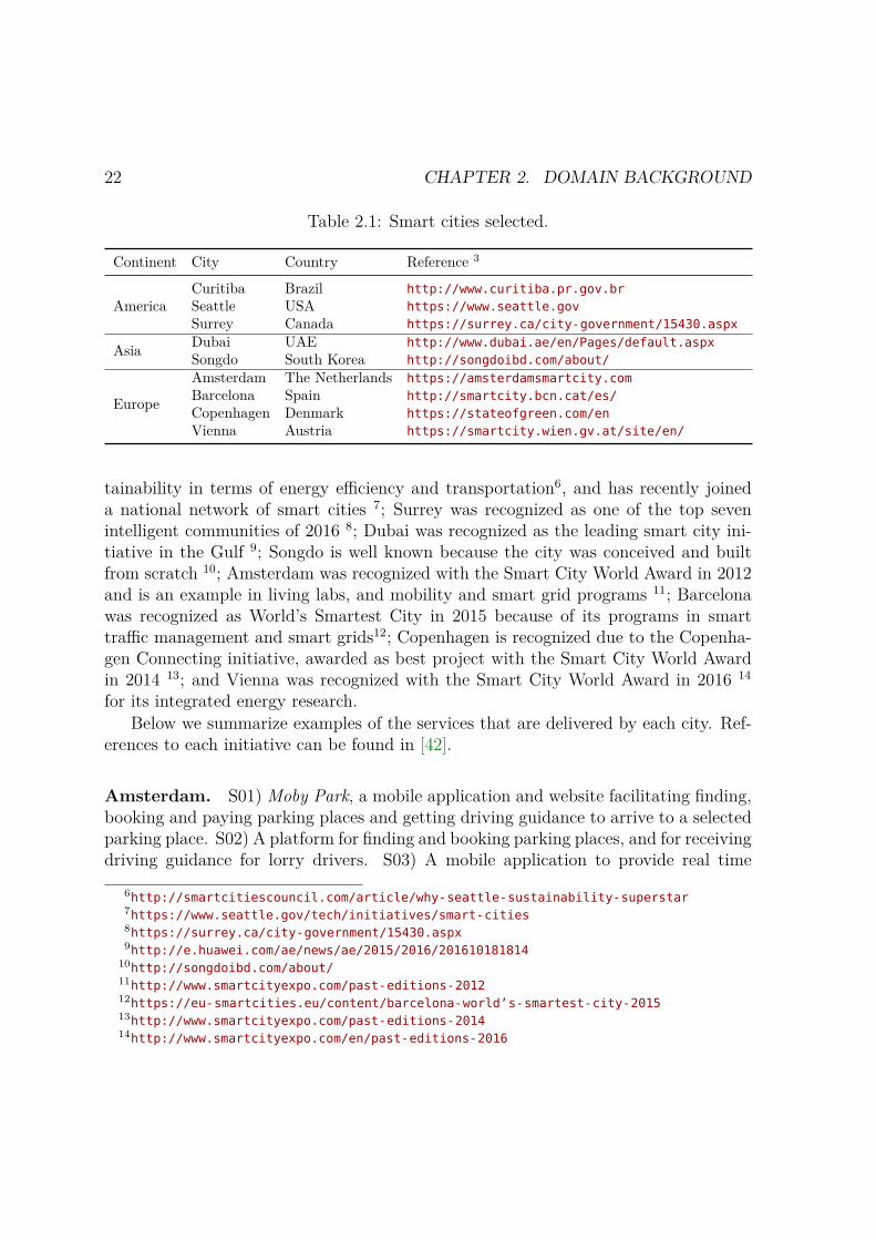
22 CHAPTER 2. DOMAIN BACKGROUND
Table 2.1: Smart cities selected.
Continent City Country Reference 3
AmericaCuritiba Brazil http://www.curitiba.pr.gov.brSeattle USA https://www.seattle.govSurrey Canada https://surrey.ca/city-government/15430.aspx
Asia Dubai UAE http://www.dubai.ae/en/Pages/default.aspxSongdo South Korea http://songdoibd.com/about/
Europe
Amsterdam The Netherlands https://amsterdamsmartcity.comBarcelona Spain http://smartcity.bcn.cat/es/Copenhagen Denmark https://stateofgreen.com/enVienna Austria https://smartcity.wien.gv.at/site/en/
tainability in terms of energy efficiency and transportation6, and has recently joineda national network of smart cities 7; Surrey was recognized as one of the top sevenintelligent communities of 2016 8; Dubai was recognized as the leading smart city ini-tiative in the Gulf 9; Songdo is well known because the city was conceived and builtfrom scratch 10; Amsterdam was recognized with the Smart City World Award in 2012and is an example in living labs, and mobility and smart grid programs 11; Barcelonawas recognized as World’s Smartest City in 2015 because of its programs in smarttraffic management and smart grids12; Copenhagen is recognized due to the Copenha-gen Connecting initiative, awarded as best project with the Smart City World Awardin 2014 13; and Vienna was recognized with the Smart City World Award in 2016 14
for its integrated energy research.Below we summarize examples of the services that are delivered by each city. Ref-
erences to each initiative can be found in [42].
Amsterdam. S01) Moby Park, a mobile application and website facilitating finding,booking and paying parking places and getting driving guidance to arrive to a selectedparking place. S02) A platform for finding and booking parking places, and for receivingdriving guidance for lorry drivers. S03) A mobile application to provide real time
6http://smartcitiescouncil.com/article/why-seattle-sustainability-superstar7https://www.seattle.gov/tech/initiatives/smart-cities8https://surrey.ca/city-government/15430.aspx9http://e.huawei.com/ae/news/ae/2015/2016/201610181814
10http://songdoibd.com/about/11http://www.smartcityexpo.com/past-editions-201212https://eu-smartcities.eu/content/barcelona-world’s-smartest-city-201513http://www.smartcityexpo.com/past-editions-201414http://www.smartcityexpo.com/en/past-editions-2016

2.4. SMART MOBILITY SERVICES 23
driving guidance, using calendar data to suggest when to start driving so to arrive ontime to scheduled appointments. S04) A mobile application to provide real time drivingguidance to emergency vehicles. S05) WeGo, a peer-to-peer car-sharing platform for carowners to share their cars, and for non-car owners to find, book and pay for availablecars. It also enables to lock and unlock cars.
Vienna. S06) An energy saving tram that monitors different aspects of the jour-neys and takes proactive measures to increase passengers’ comfort, e.g., it controls theamount of incoming fresh air and sunlight. S07) Smile, a mobile app to plan multi-modal journeys, to book and pay mobility services, to open doors at parking placesand shared vehicles, and to access mobility records.
Copenhagen. S08) Copenhagen Connecting, an integrated system tracking movingassets for security or location purposes, sharing real time data about parking places,and monitoring and controlling traffic flow on real time. It also enables traffic lightoptimization, and dynamic pricing of parking and road tolls based on current parkingdemand and traffic flow. S09) A cloud-based dashboard to study the efficiency of trafficlight patterns, traffic behaviour, and correlations between traffic and other influencingfactors. S10) An integrated system to coordinate traffic lights and provide faster greenlights for buses, to detect parking places, to inform passengers about delays and altern-ative routes, and to widen or shrink lanes on rush hours through dynamic led signs.S11) Rejseplanen, a real time multi-modal journey planner with customizable searches,and displays with information about transport. S12) An short messaging service (SMS)to buy public transport tickets.
Barcelona. S13) A remote device for blind people to command traffic lights to emitan audible sound to safely cross the street. S14) An intelligent traffic light system tocontrol traffic lights and to provide faster green lights for emergency vehicles. S15)ApparkB, a mobile app to pay street parking places, providing access to a monthlysummary of expenses. S16) App&Town, a real time multi-modal journey planner forpublic transport gathering information from various sources. S17) An SMS service toaccess transport-related information, including availability of public bicycles, and carsseized by authorities. S18) JoinUp Taxi, a mobile app to share a taxi, rate taxi driversand users, estimating money and carbon dioxide (CO2) emissions saved by sharing ataxi. S19) WeSmartPark, a mobile app and website to find available parking places,get driving guidance, book places, issue payments when leaving the parking place, andautomatically opening parking doors.

24 CHAPTER 2. DOMAIN BACKGROUND
Curitiba. S20) Services for public buses including wireless Internet on-board, andsmart pass payment, providing real time information about the service; and monitoringvehicles and their performance, e.g., measuring passenger demand to send more vehiclesto cover a route, and comparing estimated traveling times with actual times. S21)A service providing online integrated itinerary comprising information about varioustypes of buses. S22) A service estimating traveling times by detecting and monitoringcars entering and leaving specific locations. S23) A system to control traffic lightsbased on current traffic conditions or by request. S24) A system providing faster greenlights for public buses, and monitoring buses to identify critical and optimal roadintersections to improve traveling times. S25) A system providing real time trafficinformation through dynamic message signs. S26) An operational control centre tomonitor traffic and incidents in real time through closed-circuit television (CCTV).S27) Radars and cameras to detect vehicles that exceed the speed limit, fail to stop ona red light, or stop on the pedestrian walk.
Songdo. S28) A system for optimizing traffic light aiming at resolving traffic con-gestions, which are detected by analysing geo-location information provided by radio-frequency identification (RFID) tags on cars.
Seattle. S29) A website providing real time information of available parking places,and a system of dynamic message signs providing guidance to the nearest availableparking place . S30) Online payment of parking and traffic fines. S31) An onlineinteractive map with information about planned events that affect mobility. S32) Asystem to monitor traffic flows and to automatically detect license plates for securityand law enforcement, estimating traveling times. S33) A system to adjust traffic lightsbased on historical and current data, and to provide faster green lights for public buses.S34) A system providing real time information about traffic through dynamic messagesigns. S35) An online interactive map publishing real time traffic information, includingincidents, planned events, and access to CCTV cameras feeds.
Dubai. S36) Nol Card, a smart card to seamlessly pay for different mobility services,including public transport and parking places. S37) Smart Taxi, a mobile app to requesttaxis, choose the type of vehicle, find out the location of taxis, get information aboutthe driver, and rate the drivers driving skills. S38) A multi-modal journey planner withcustomizable searches and estsimations of traveling times and costs. S39) A mobile appto find nearby available parking places and to receive driving guidance to reach theparking place.

2.4. SMART MOBILITY SERVICES 25
Surrey. S40) A mobile application for car-pooling. S41) A website for car-sharing,including a booking service. S42) A system to control traffic lights and to adjust themfor faster emergency responses, as well as to guide emergency vehicles, and to analysetraffic behaviour.

26 CHAPTER 2. DOMAIN BACKGROUND
Chapter 3
A Taxonomy of Smart MobilityServices
With the aim of addressing the lack of structured information and deepening the know-ledge in smart mobility services, as well as to address research questions RQ1, RQ2,and RQ3, we analysed the state of the art described Section 2.4. Based on the ana-lysis and findings, we propose a taxonomy for planning and designing smart mobilityservices. The taxonomy comprises eight dimensions: 1) type of services, 2) maturitylevel, 3) type of users, 4) applied technologies, 5) delivery channels, 6) benefits, 7)beneficiaries, and 8) common functionality.
The structuring nature of taxonomies enables to identify and define common con-cepts for each of the dimensions, providing a common vocabulary to discuss and shareinformation about smart mobility services. In addition, it provides a specialized andcontextualized tool for policy makers involved in the development of smart mobilityinitiatives. In particular, the concrete dimensions identify the spectrum of mobilityservices that can be provided, to whom they are provided, what technologies can beused to deliver them, and the public value that is delivered through each kind of service.Identifying common functionality can also help software engineers and IT staff to im-plement smart mobility services through reusable components, ready to be configuredand integrated into software applications.
Chapter Organization: Some background on how taxonomies are built is presentedin Section 3.1. Section 3.2 describes the methodology used for building the taxonomy.Section 3.3 introduces the proposed taxonomy. Sections 3.4 to 3.6 discuss the valid-ation and maintainability of the taxonomy, and some challenges and lessons learnt,respectively.
27

28 CHAPTER 3. A TAXONOMY OF SMART MOBILITY SERVICES
3.1 Building TaxonomiesTaxonomy is the science of classification. It structures information of a given domaininto groups and lays out their relations, providing a conceptual framework for discus-sion, analysis, and information retrieval [28]. We use a taxonomy since we are merelyconcerned with the classification of concepts, although it can be later evolved into anontology with richer relations and characterization of the concepts. Below we discusssome key aspects of taxonomy development.
3.1.1 Taxonomy StructureThe most common types of relations between concepts are hierarchies, trees, and fa-ceted [101]. We focus on the faceted structure due to its many advantages. Theapproach considers that there are multiple perspectives or facets to model a concept.Main advantages include: 1) hospitability – it does not require a complete knowledge ofthe domain. This is attractive for emerging or changing domains, as the smart mobilitydomain, which is continuously evolving due to advances in technology and changingneeds; 2) flexible searches – facilitates recovering information in multiple ways; e.g.,some of the benefits delivered by type of service; 3) greater expressiveness – each facetcan use the structure that best suits the knowledge that it represents; and 4) flexibility– each concept can accommodate multiple perspectives. As a limitation, facets do notexplicitly express meaningful relations between concepts.
3.1.2 Taxonomy DevelopmentCategories in a taxonomy are constructed following an iterative process. In each iter-ation a development approach is selected and at the end of the process it is analysedif categories are well defined, need to be merged, or if new ones can be identified [120].
There are three well known development approaches [18]: 1) conceptual, 2) empir-ical, and 3) operational. The last one is a combination of the previous two and is themost commonly used in practice.
An operational approach can follow two development patterns. On the one hand,conceptual to empirical, where categories are first conceptualized following a deductiveprocess, based on theory, domain knowledge, or experience, and then empirical casesare identified for each concept. On the other hand, empirical to conceptual, where aseries of empirical cases are first identified, analysed and grouped based on recognizedsimilarities, and then conceptual labels are formulated for them.
In addition, various methodologies and best practices exist for taxonomy develop-

3.2. METHODOLOGY 29
ment. We identify three that are generic enough to easily adapt to our domain 1: 1)BR [28], and 2) CJ [32] – both focusing on organizational aspects; and 3) NVM [120]– focusing on information systems. We believe that the three methodologies comple-ment each other, and as such, we propose a methodology combining guidance andsteps from all of them. In particular, NVM recognizes the need for an iterative devel-opment process and provides guidance for selecting a development strategy, the criteriato develop a useful taxonomy and how to use such criteria to evaluate the taxonomy;BR recognises the need of a data collection process; and BR and CJ distinguish dif-ferent taxonomy structures and provide guidance for maintaining the taxonomy. Theproposed methodology is described in Section 3.2
3.2 Methodology
The proposed methodology for taxonomy development comprises five steps: 1) Plan-ning, 2) Data Collection, 3) Taxonomy Construction, 4) Validation, and 5) Mainten-ance. A comprehensive view of the methodology is depicted in Figure 3.1, includingthe five main activities, tasks involved in each activity and some results obtained. Theactivities conducted and decisions made in each step are described in the followingsections.
3.2.1 Planning
This step provides the foundations to develop the taxonomy. It defines the goals andscope of the taxonomy, meta-characteristics, ending conditions, and structure of thetaxonomy.
Goals, Scope, and Meta-characteristics. The goal is to structure knowledge re-lated to smart mobility services. The scope of the taxonomy is limited to smart mobilityservices, in particular, software intensive services, with limited attention given to ser-vices depending mainly on non-software technologies, such as electric vehicles. Theresearch questions RQ1, RQ2 and RQ3 formulated in Section 1.2 serve as the meta-characteristics of the taxonomy, i.e. they represent the most comprehensive character-istics that will serve to determine the features of the taxonomy. The main dimensionsof the taxonomy should be a logical consequence of these meta-characteristics.
1We use the authors initials to identified them i.e. BR, CJ, and NVM.
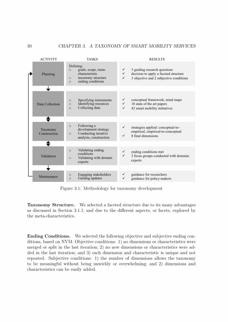
30 CHAPTER 3. A TAXONOMY OF SMART MOBILITY SERVICES
Planning
Defining: o goals, scope, meta-
characteristic o taxonomy structure o ending conditions
ü 3 guiding research questions ü decision to apply a faceted structure ü 3 objective and 2 subjective conditions
Data Collection o Specifying instruments o Identifying resources o Collecting data
ü conceptual framework, mind maps ü 18 state of the art papers ü 42 smart mobility initiatives
Taxonomy Construction
o Following a development strategy
o Conducting iterative analysis, construction
ü strategies applied: conceptual-to-empirical, empirical-to-conceptual
ü 8 final dimensions
Validation
o Validating ending conditions
o Validating with domain experts
ü ending conditions met ü 2 focus groups conducted with domains
experts
Maintenance ü guidance for researchers ü guidance for policy-makers
o Engaging stakeholders o Guiding updates
ACTIVITY TASKS RESULTS
Figure 3.1: Methodology for taxonomy development
Taxonomy Structure. We selected a faceted structure due to its many advantagesas discussed in Section 3.1.1, and due to the different aspects, or facets, explored bythe meta-characteristics.
Ending Conditions. We selected the following objective and subjective ending con-ditions, based on NVM. Objective conditions: 1) no dimensions or characteristics weremerged or split in the last iteration; 2) no new dimensions or characteristics were ad-ded in the last iteration; and 3) each dimension and characteristic is unique and notrepeated. Subjective conditions: 1) the number of dimensions allows the taxonomyto be meaningful without being unwieldy or overwhelming; and 2) dimensions andcharacteristics can be easily added.
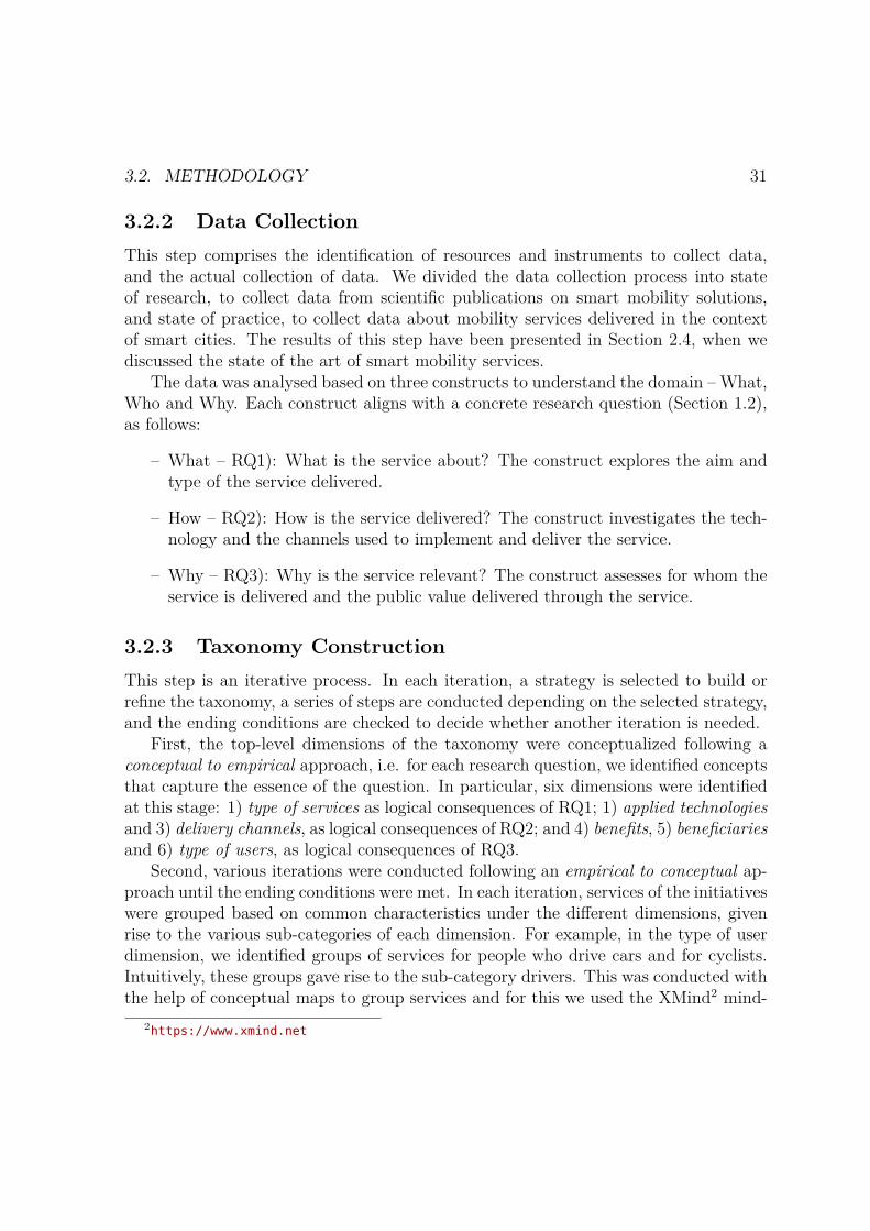
3.2. METHODOLOGY 31
3.2.2 Data CollectionThis step comprises the identification of resources and instruments to collect data,and the actual collection of data. We divided the data collection process into stateof research, to collect data from scientific publications on smart mobility solutions,and state of practice, to collect data about mobility services delivered in the contextof smart cities. The results of this step have been presented in Section 2.4, when wediscussed the state of the art of smart mobility services.
The data was analysed based on three constructs to understand the domain – What,Who and Why. Each construct aligns with a concrete research question (Section 1.2),as follows:
– What – RQ1): What is the service about? The construct explores the aim andtype of the service delivered.
– How – RQ2): How is the service delivered? The construct investigates the tech-nology and the channels used to implement and deliver the service.
– Why – RQ3): Why is the service relevant? The construct assesses for whom theservice is delivered and the public value delivered through the service.
3.2.3 Taxonomy ConstructionThis step is an iterative process. In each iteration, a strategy is selected to build orrefine the taxonomy, a series of steps are conducted depending on the selected strategy,and the ending conditions are checked to decide whether another iteration is needed.
First, the top-level dimensions of the taxonomy were conceptualized following aconceptual to empirical approach, i.e. for each research question, we identified conceptsthat capture the essence of the question. In particular, six dimensions were identifiedat this stage: 1) type of services as logical consequences of RQ1; 1) applied technologiesand 3) delivery channels, as logical consequences of RQ2; and 4) benefits, 5) beneficiariesand 6) type of users, as logical consequences of RQ3.
Second, various iterations were conducted following an empirical to conceptual ap-proach until the ending conditions were met. In each iteration, services of the initiativeswere grouped based on common characteristics under the different dimensions, givenrise to the various sub-categories of each dimension. For example, in the type of userdimension, we identified groups of services for people who drive cars and for cyclists.Intuitively, these groups gave rise to the sub-category drivers. This was conducted withthe help of conceptual maps to group services and for this we used the XMind2 mind-
2https://www.xmind.net

32 CHAPTER 3. A TAXONOMY OF SMART MOBILITY SERVICES
mapping tool. During this process, it was evident that many services provided similarfunctionality with small variations, resulting in the identification of another dimension,7) common functionality, which can be seen as a logical consequence of RQ2.
3.2.4 Validation
This step comprises the validation of the taxonomy and the integration of the receivedfeedback. We organized two focus groups meetings with international governmentpractitioners and academic experts with experience on the smart mobility domain.
The two meetings conducted in Guimarães, Portugal, one at Comunidade Intermu-nicipal do Ave 3 and one at United Nations Universit-EGOV (UNU-EGOV) 4, wereorganized as two-hour session, including 20-minutes presentation of the taxonomy, fol-lowed by a discussion among participants. The aim was to discuss the suitability ofthe taxonomy, validity of the concepts, completeness, weaknesses, and improvements.In total, the meetings were attended by five government experts from China (workingfor Beijing Government), Uganda (working for Ministry of ICT, Uganda), Portugal(working for Comunidade Intermunicipal do Ave), and Denmark (former governmentofficial of the Danish Agency for Digitization), and four academics from UNU-EGOV.
Both meetings provided valuable feedback for validating the content of the tax-onomy as well as for its improvement. In particular, a new dimension was incorporated,8) level of maturity, which can be seen as a logical consequence of RQ2. This resultedin a new iteration of step 3, where the characteristics for this dimension were identifiedfollowing a conceptual to empirical approach based on existing theory.
In addition to the feedback received during the two focus groups, the content of thetaxonomy has been validated based on traceability, i.e. the content has been producedonly based on collected data and references are provided for each concept.
3.2.5 Maintenance
This step comprises the identification of the stakeholders responsible for the continuedmaintenance and evolution of the taxonomy, and the definition of guidelines for thestakeholders. These topics are discussed in Section 3.5.
3http://www.cim-ave.pt4https://egov.unu.edu

3.3. A TAXONOMY OF SMART MOBILITY SERVICES 33
3.3 A taxonomy of smart mobility servicesThe main dimensions defined for the taxonomy of smart mobility services are depictedin Figure 3.2. The identified values for each dimension are defined and illustrated inthe following sections.
Type ofService
Level ofMaturity
Type ofUser Technology Delivery
Channels Benefits Beneficiaries
CommonFunctionality
Smart MobilityService
Figure 3.2: Defining a smart mobility service taxonomy
3.3.1 Type of ServicesWe identify 12 types of services. Table 3.1 describes each type and exemplifies it byclassifying each initiative described in Sections 2.4.1 and 2.4.2.
Table 3.1: Type of service
Category Description Examples
Drivingguidance
It provides guidance to drivers about the best route for movingfrom one place to another, including fixed or real time informa-tion of issues affecting mobility. Routes can be selected based ondifferent criteria, such as the shortest or fastest route.
S01, S02, S03,S04, S19, S39,S42, P18
Improvingtransportinfra-structure
It refers to enhanced functionality included in transport resources,usually related to a specific goal, such as energy savings, enhancingthe travel experience, and reducing CO2 emissions.
S06, S20, P13,P14, P15
Improvingtransportinfra-structure
It refers to enhanced functionality delivered to transport infra-structure such as parking places, roads, traffic lights, etc., includ-ing devices to detect empty parking places, or dynamic messagesigns to inform about traffic.
S07, S10, S13,S19, S25, S29,S34
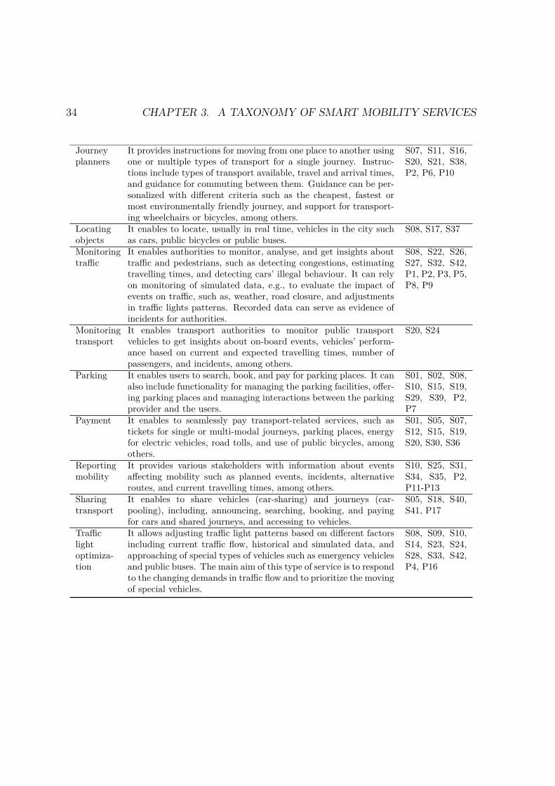
34 CHAPTER 3. A TAXONOMY OF SMART MOBILITY SERVICES
Journeyplanners
It provides instructions for moving from one place to another usingone or multiple types of transport for a single journey. Instruc-tions include types of transport available, travel and arrival times,and guidance for commuting between them. Guidance can be per-sonalized with different criteria such as the cheapest, fastest ormost environmentally friendly journey, and support for transport-ing wheelchairs or bicycles, among others.
S07, S11, S16,S20, S21, S38,P2, P6, P10
Locatingobjects
It enables to locate, usually in real time, vehicles in the city suchas cars, public bicycles or public buses.
S08, S17, S37
Monitoringtraffic
It enables authorities to monitor, analyse, and get insights abouttraffic and pedestrians, such as detecting congestions, estimatingtravelling times, and detecting cars’ illegal behaviour. It can relyon monitoring of simulated data, e.g., to evaluate the impact ofevents on traffic, such as, weather, road closure, and adjustmentsin traffic lights patterns. Recorded data can serve as evidence ofincidents for authorities.
S08, S22, S26,S27, S32, S42,P1, P2, P3, P5,P8, P9
Monitoringtransport
It enables transport authorities to monitor public transportvehicles to get insights about on-board events, vehicles’ perform-ance based on current and expected travelling times, number ofpassengers, and incidents, among others.
S20, S24
Parking It enables users to search, book, and pay for parking places. It canalso include functionality for managing the parking facilities, offer-ing parking places and managing interactions between the parkingprovider and the users.
S01, S02, S08,S10, S15, S19,S29, S39, P2,P7
Payment It enables to seamlessly pay transport-related services, such astickets for single or multi-modal journeys, parking places, energyfor electric vehicles, road tolls, and use of public bicycles, amongothers.
S01, S05, S07,S12, S15, S19,S20, S30, S36
Reportingmobility
It provides various stakeholders with information about eventsaffecting mobility such as planned events, incidents, alternativeroutes, and current travelling times, among others.
S10, S25, S31,S34, S35, P2,P11-P13
Sharingtransport
It enables to share vehicles (car-sharing) and journeys (car-pooling), including, announcing, searching, booking, and payingfor cars and shared journeys, and accessing to vehicles.
S05, S18, S40,S41, P17
Trafficlightoptimiza-tion
It allows adjusting traffic light patterns based on different factorsincluding current traffic flow, historical and simulated data, andapproaching of special types of vehicles such as emergency vehiclesand public buses. The main aim of this type of service is to respondto the changing demands in traffic flow and to prioritize the movingof special vehicles.
S08, S09, S10,S14, S23, S24,S28, S33, S42,P4, P16

3.3. A TAXONOMY OF SMART MOBILITY SERVICES 35
3.3.2 Level of MaturityWe define level of maturity following the United Nations four-stage digital public ser-vice maturity model [104] to classify standard digital public services, and the digitalpublic service innovation framework proposed in [26] to classify innovative digital pub-lic services. Table 3.2 describes each level of maturity and classifies each initiative.Example services were identified for all categories.
Table 3.2: Level of maturity
Category Description Examples
Standard Services
Emerging Informational services providing basic online informa-tion with only one-way interaction between users andthe service provider.
S25, S29
Enhanced Services with enhanced one-way communication or ba-sic two-way interactions between users and the serviceprovider.
S31
Transactional Services enabling complete transactions online with two-way communication between users and the service pro-vider.
S13, S17, S30
Connected Integrated seamless services, delivered using multipletechnologies and platforms, and highly interactive.
S01-S05, S07-S12,S14-S16, S18-S21,S24-S27, S29, S32-S42
Innovative Services
Transparent Services publishing information about service contextand decisions made by the service provider.
S07, S31, S35, S37
Participatory Services using participatory techniques such as crowd-sourcing.
S16, S18
Anticipatory Services that anticipate to the needs of the user. S03Co-created Services delivered collaboratively between government,
private sector, and/or non-government organizations,and/or citizens.
S01, S05, S18, S40,S41
Personalized Customizable service delivery based on user’s prefer-ences and specific needs.
S07, S11, S16, S18,S38
Context-aware
Services or information provided based on the user’s con-text information.
S01, S02, S04, S07,S10, S20, S39
Context-smart
Services that apply intelligence and leverage on theknowledge of context-related information to take actionat the needed moment.
S02-S03, S06, S08-S10, S14, S19, S22-S24, S28, S33
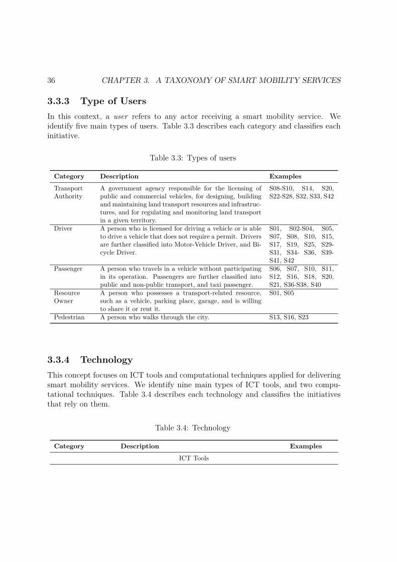
36 CHAPTER 3. A TAXONOMY OF SMART MOBILITY SERVICES
3.3.3 Type of UsersIn this context, a user refers to any actor receiving a smart mobility service. Weidentify five main types of users. Table 3.3 describes each category and classifies eachinitiative.
Table 3.3: Types of users
Category Description Examples
TransportAuthority
A government agency responsible for the licensing ofpublic and commercial vehicles, for designing, buildingand maintaining land transport resources and infrastruc-tures, and for regulating and monitoring land transportin a given territory.
S08-S10, S14, S20,S22-S28, S32, S33, S42
Driver A person who is licensed for driving a vehicle or is ableto drive a vehicle that does not require a permit. Driversare further classified into Motor-Vehicle Driver, and Bi-cycle Driver.
S01, S02-S04, S05,S07, S08, S10, S15,S17, S19, S25, S29-S31, S34- S36, S39-S41, S42
Passenger A person who travels in a vehicle without participatingin its operation. Passengers are further classified intopublic and non-public transport, and taxi passenger.
S06, S07, S10, S11,S12, S16, S18, S20,S21, S36-S38, S40
ResourceOwner
A person who possesses a transport-related resource,such as a vehicle, parking place, garage, and is willingto share it or rent it.
S01, S05
Pedestrian A person who walks through the city. S13, S16, S23
3.3.4 TechnologyThis concept focuses on ICT tools and computational techniques applied for deliveringsmart mobility services. We identify nine main types of ICT tools, and two compu-tational techniques. Table 3.4 describes each technology and classifies the initiativesthat rely on them.
Table 3.4: Technology
Category Description Examples
ICT Tools
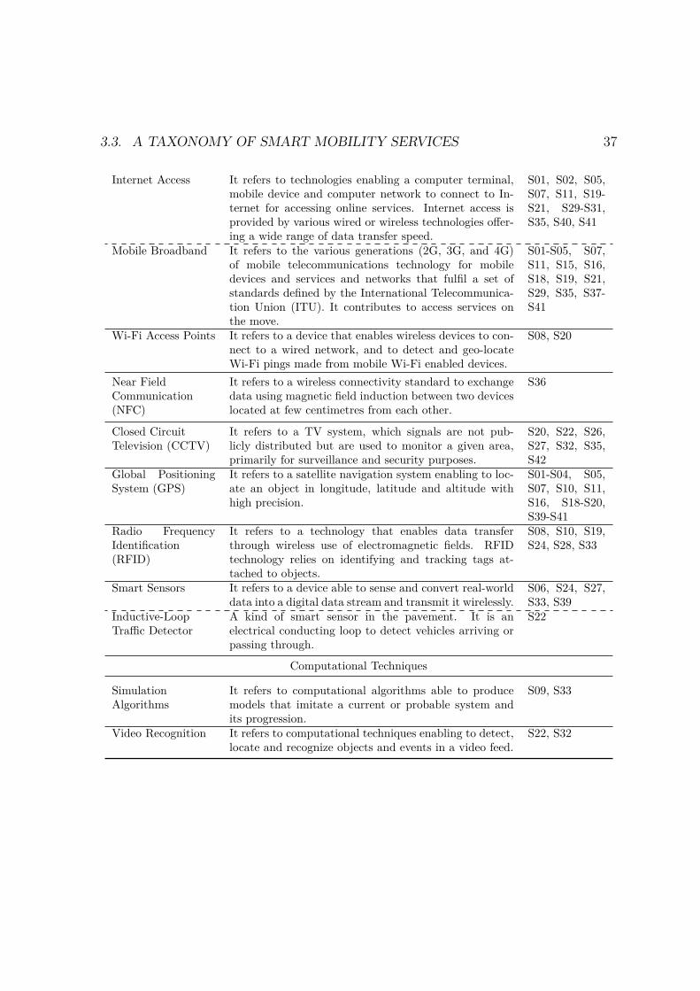
3.3. A TAXONOMY OF SMART MOBILITY SERVICES 37
Internet Access It refers to technologies enabling a computer terminal,mobile device and computer network to connect to In-ternet for accessing online services. Internet access isprovided by various wired or wireless technologies offer-ing a wide range of data transfer speed.
S01, S02, S05,S07, S11, S19-S21, S29-S31,S35, S40, S41
Mobile Broadband It refers to the various generations (2G, 3G, and 4G)of mobile telecommunications technology for mobiledevices and services and networks that fulfil a set ofstandards defined by the International Telecommunica-tion Union (ITU). It contributes to access services onthe move.
S01-S05, S07,S11, S15, S16,S18, S19, S21,S29, S35, S37-S41
Wi-Fi Access Points It refers to a device that enables wireless devices to con-nect to a wired network, and to detect and geo-locateWi-Fi pings made from mobile Wi-Fi enabled devices.
S08, S20
Near FieldCommunication(NFC)
It refers to a wireless connectivity standard to exchangedata using magnetic field induction between two deviceslocated at few centimetres from each other.
S36
Closed CircuitTelevision (CCTV)
It refers to a TV system, which signals are not pub-licly distributed but are used to monitor a given area,primarily for surveillance and security purposes.
S20, S22, S26,S27, S32, S35,S42
Global PositioningSystem (GPS)
It refers to a satellite navigation system enabling to loc-ate an object in longitude, latitude and altitude withhigh precision.
S01-S04, S05,S07, S10, S11,S16, S18-S20,S39-S41
Radio FrequencyIdentification(RFID)
It refers to a technology that enables data transferthrough wireless use of electromagnetic fields. RFIDtechnology relies on identifying and tracking tags at-tached to objects.
S08, S10, S19,S24, S28, S33
Smart Sensors It refers to a device able to sense and convert real-worlddata into a digital data stream and transmit it wirelessly.
S06, S24, S27,S33, S39
Inductive-LoopTraffic Detector
A kind of smart sensor in the pavement. It is anelectrical conducting loop to detect vehicles arriving orpassing through.
S22
Computational Techniques
SimulationAlgorithms
It refers to computational algorithms able to producemodels that imitate a current or probable system andits progression.
S09, S33
Video Recognition It refers to computational techniques enabling to detect,locate and recognize objects and events in a video feed.
S22, S32
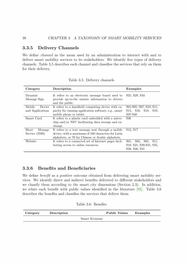
38 CHAPTER 3. A TAXONOMY OF SMART MOBILITY SERVICES
3.3.5 Delivery ChannelsWe define channel as the mean used by an administration to interact with and todeliver smart mobility services to its stakeholders. We identify five types of deliverychannels. Table 3.5 describes each channel and classifies the services that rely on themfor their delivery.
Table 3.5: Delivery channels
Category Description Examples
DynamicMessage Sign
It refers to an electronic message board used toprovide up-to-the minute information to driversand the public.
S25, S29, S34
Mobile Deviceand Applications
It refers to a handheld computing device with ca-pacity for running application software, e.g., smartmobile phone or tablet.
S01-S05, S07, S10, S11,S15, S16, S18, S19,S37-S40
Smart Card It refers to a plastic card embedded with a micro-chip and/or NFC facilitating data storage and ex-change.
S36
Short MessageService (SMS)
It refers to a text message sent through a mobiledevice, with a maximum of 160 characters for Latinalphabets, or 70 for Chinese or Arabic alphabets.
S12, S17
Website It refers to a connected set of Internet pages facil-itating access to online resources.
S01, S02, S05, S11,S19, S21, S29-S31, S35,S38, S40, S41
3.3.6 Benefits and BeneficiariesWe define benefit as a positive outcome obtained from delivering smart mobility ser-vices. We identify direct and indirect benefits delivered to different stakeholders andwe classify them according to the smart city dimensions (Section 2.3). In addition,we relate each benefit with public values identified in the literature [92]. Table 3.6describes the benefits and classifies the services that deliver them.
Table 3.6: Benefits
Category Description Public Values Examples
Smart Economy
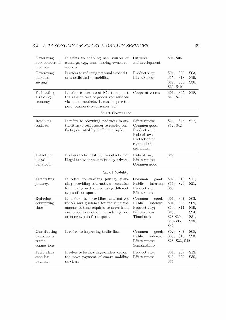
3.3. A TAXONOMY OF SMART MOBILITY SERVICES 39
Generatingnew sources ofincomes
It refers to enabling new sources ofearnings, e.g., from sharing owned re-sources.
Citizen’sself-development
S01, S05
Generatingpersonalsavings
It refers to reducing personal expendit-ures dedicated to mobility.
Productivity;Effectiveness
S01, S02, S03,S15, S18, S19,S29, S30, S36,S39, S40
Facilitatinga sharingeconomy
It refers to the use of ICT to supportthe sale or rent of goods and servicesvia online markets. It can be peer-to-peer, business to consumer, etc.
Cooperativeness S01, S05, S18,S40, S41
Smart Governance
Resolvingconflicts
It refers to providing evidences to au-thorities to react faster to resolve con-flicts generated by traffic or people.
Effectiveness;Common good;Productivity;Rule of law;Protection ofrights of theindividual
S20, S26, S27,S32, S42
Detectingillegalbehaviour
It refers to facilitating the detection ofillegal behaviour committed by drivers.
Rule of law;Effectiveness;Common good
S27
Smart Mobility
Facilitatingjourneys
It refers to enabling journey plan-ning providing alternatives scenariosfor moving in the city using differenttypes of transport.
Common good;Public interest;Productivity;Effectiveness
S07, S10, S11,S16, S20, S21,S38
Reducingcommutingtime
It refers to providing alternativesroutes and guidance for reducing theamount of time required to move fromone place to another, considering oneor more types of transport.
Common good;Public interest;Productivity;Effectiveness;Timeliness
S01, S02, S03,S04, S08, S09,S10, S14, S19,S23, S24,S28,S29, S31,S33-S35, S39,S42
Contributingto reducingtrafficcongestions
It refers to improving traffic flow. Common good;Public interest;Effectiveness;Sustainability
S02, S03, S08,S09, S10, S23,S28, S33, S42
Facilitatingseamlesspayment
It refers to facilitating seamless and on-the-move payment of smart mobilityservices.
Productivity;Effectiveness
S01, S07, S12,S19, S20, S30,S36
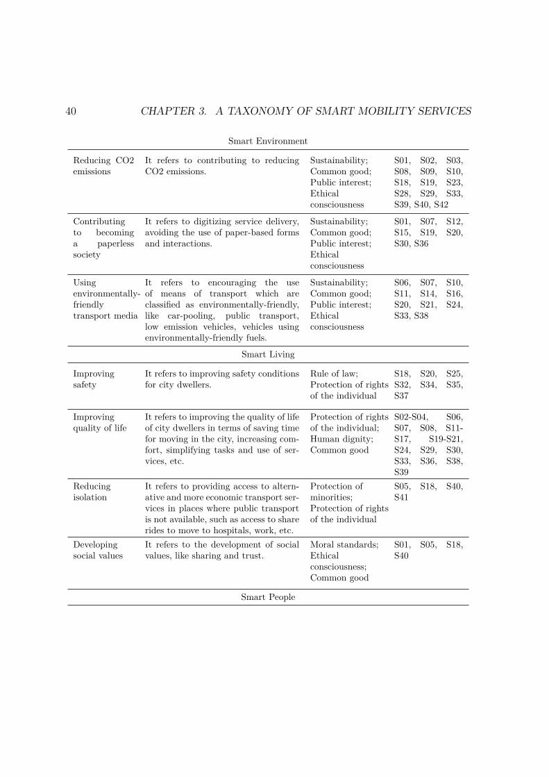
40 CHAPTER 3. A TAXONOMY OF SMART MOBILITY SERVICES
Smart Environment
Reducing CO2emissions
It refers to contributing to reducingCO2 emissions.
Sustainability;Common good;Public interest;Ethicalconsciousness
S01, S02, S03,S08, S09, S10,S18, S19, S23,S28, S29, S33,S39, S40, S42
Contributingto becominga paperlesssociety
It refers to digitizing service delivery,avoiding the use of paper-based formsand interactions.
Sustainability;Common good;Public interest;Ethicalconsciousness
S01, S07, S12,S15, S19, S20,S30, S36
Usingenvironmentally-friendlytransport media
It refers to encouraging the useof means of transport which areclassified as environmentally-friendly,like car-pooling, public transport,low emission vehicles, vehicles usingenvironmentally-friendly fuels.
Sustainability;Common good;Public interest;Ethicalconsciousness
S06, S07, S10,S11, S14, S16,S20, S21, S24,S33, S38
Smart Living
Improvingsafety
It refers to improving safety conditionsfor city dwellers.
Rule of law;Protection of rightsof the individual
S18, S20, S25,S32, S34, S35,S37
Improvingquality of life
It refers to improving the quality of lifeof city dwellers in terms of saving timefor moving in the city, increasing com-fort, simplifying tasks and use of ser-vices, etc.
Protection of rightsof the individual;Human dignity;Common good
S02-S04, S06,S07, S08, S11-S17, S19-S21,S24, S29, S30,S33, S36, S38,S39
Reducingisolation
It refers to providing access to altern-ative and more economic transport ser-vices in places where public transportis not available, such as access to sharerides to move to hospitals, work, etc.
Protection ofminorities;Protection of rightsof the individual
S05, S18, S40,S41
Developingsocial values
It refers to the development of socialvalues, like sharing and trust.
Moral standards;Ethicalconsciousness;Common good
S01, S05, S18,S40
Smart People

3.3. A TAXONOMY OF SMART MOBILITY SERVICES 41
Developinge-skills
It refers to enabling the development ofdigital skills by using digital services.The substantial benefits provided bydigital services could encourage digitalilliterates to learn how to use them,while they continue to increase theknowledge of those already digital lit-erate.
Citizensself-development
S01-S05, S07-S12, S15-S24,S26, S29, S30-S33, S35, S37-S42
Associated with benefits, we can identify beneficiaries. A beneficiary refers to theactor who receives a benefit from a smart mobility service. From the types of usersidentified in Section 3.3.3, we identify transport authority, driver, passenger, and re-source owner, as beneficiaries. We also identify the society, as beneficiary, representingall kind of social actors. Table 3.7 illustrates this relationship. In addition, due tothe faceted structure, we can easily relate information in multiple ways. Thus, we canrelate types of services with benefits delivered; as Figure 3.3 shows the type of servicecontributing to delivering each benefit.
Table 3.7: Benefits and beneficiaries
ID Benefits TA D P RO S
B1 Generating new sources of income X XB2 Generating personal savings X X XB3 Facilitating a sharing economy X X XB4 Resolving conflicts X XB5 Detecting illegal behaviour X X XB6 Facilitating journeys XB7 Reducing commuting time X XB8 Contributing to reducing traffic congestions X XB9 Facilitating seamless payment X XB10 Reducing CO2 emissions XB11 Contributing to becoming paperless society XB12 Using environmentally-friendly transport media XB13 Improving safety X X XB14 Improving quality of life X XB15 Reducing isolation XB16 Developing social values X X X XB17 Developing e-skills X X X X XTA = Transport Authority; D = Drivers; P = Passengers; RO = Resource Owners; S = Society
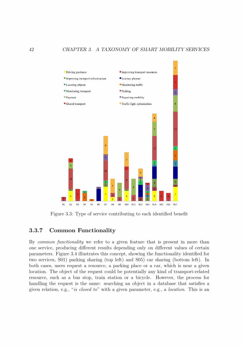
42 CHAPTER 3. A TAXONOMY OF SMART MOBILITY SERVICES
Figure 3.3: Type of service contributing to each identified benefit
3.3.7 Common Functionality
By common functionality we refer to a given feature that is present in more thanone service, producing different results depending only on different values of certainparameters. Figure 3.4 illustrates this concept, showing the functionality identified fortwo services, S01) parking sharing (top left) and S05) car sharing (bottom left). Inboth cases, users request a resource, a parking place or a car, which is near a givenlocation. The object of the request could be potentially any kind of transport-relatedresource, such as a bus stop, train station or a bicycle. However, the process forhandling the request is the same: searching an object in a database that satisfies agiven relation, e.g., “is closed to” with a given parameter, e.g., a location. This is an

3.3. A TAXONOMY OF SMART MOBILITY SERVICES 43
example of common functionality used by more than one service. We call such function“request nearby resource” and the parameters include type of resource and location. Thecommon functionality and expected parameters identified for both services is shown inFigure 3.4 (right).
Figure 3.4: Example of common functionality for two smart mobility services.
A summary of the common functionality identified in smart mobility services to-gether with the services that use such functions is presented in Table 3.8.
Table 3.8: Common functionality
Category Description Examples
Requesting nearresources
It enables requesting and obtaining from a database allthe resources of a given type that are located near agiven location.
S07, S16, S21
Requestingavailable nearbyresources
It enables requesting and obtaining from a database allthe resources of a given type that are located near agiven location and are available at a given timestamp.
S01, S02, S05,S07, S16, S17,S19, S21, S29,S37, S41

44 CHAPTER 3. A TAXONOMY OF SMART MOBILITY SERVICES
Requestingguidance to moveto a location
It enables requesting and obtaining concrete instructionsto move from a starting point to a destination pointby using one or more means of transportation specified.The guidance can be provided with different levels ofprecision based on different factors, including distanceand real time traffic information, among others.
S01-S04, S07, S11,S16, S19, S21,S38, S39
Calculatingarrival time
It calculates an estimated arrival time to reach a loca-tion from a starting point by using one or more types oftransport. The estimated time can have various levels ofprecision based on different factors, such as distance, realtime traffic information, public transport timetables,and geo-location information of a vehicle.
S02, S03, S07,S11, S16, S18,S20, S21, S38
Calculating costof a service orresource
It calculates the cost of a service or the use of a resource,such as: a journey, a parking place, etc.
S07, S38
Sharing aresource
It enables specifying data about a transport-related re-source that is offered to others.
S01, S05, S18,S19, S40, S41
Booking aresource
It enables booking a transport-related resource for agiven daytime.
S01, S02, S05,S07, S19, S41
Paying a service It enables a payment transaction made by the user of aservice or a resource to the service provider or resourceowner.
S01, S02, S05,S07, S12, S15,S19, S20, S30, S36
Locking andunlocking accessto a resource
It enables the locking and unlocking of resources throughnon-traditional channels (non-manual) such as mobiledevices, RFID, etc.
S05, S07, S19
Requestingmobility records
It enables requesting and obtaining records of mobilityservices used or paid during a given period.
S07, S15, S36
Locating aresource
It enables finding and showing the current location ofan object in a map.
S01, S02, S05,S17, S21, S29,S35, S37
3.4 ValidationThe taxonomy presented was constructed based on a detailed analysis of the state ofresearch and practice of smart mobility services, following the methodology defined inSection 3.2 and the validation approach described in Section 3.2.4. Below we discussfurther decisions underpinning the taxonomy.
The values identified for type of service have been recognized and studied in various

3.4. VALIDATION 45
Table 3.9: Type of services – References from literature
Type of Service References
Driving guidance [106,155,156]Improving transport resources [21,67,152]Improving transport infrastructure [29,68,121]Journey planners [3, 99,119]Locating objects [100]Monitoring traffic [30,100,135]Monitoring transport [77,102,153]Parking [14,117,143]Payment [27,79,123]Reporting mobility [124,137,151]Sharing transport [69,129,132]Traffic light optimization [71,96,131]
related work, as shown in Table 3.9. The level of maturity was based on well-definedexisting classifications, as discussed in Section 3.3.2. The values identified for type ofusers, technologies and delivery channels were identified directly from the descriptionof the surveyed services. No other values were added. The benefits were extractedfrom the description of the services. The criteria for classifying benefits was discussedamong the authors, and the beneficiaries derived from the service descriptions. Whilesome common functionality was extracted from the service descriptions, given the lackof detailed documentation, some other functionality was identified relying on relatedwork [60,63].
Finally, the focus group meetings enabled to validate the content of the taxonomy.In addition, many valuable ideas to improve the contributions of the taxonomy wererecorded and will be considered for future work, including: 1) digitalization of thetaxonomy and creation of an online platform where experts can contribute to the evol-ution of the taxonomy and documentation of case studies; 2) extension of the taxonomywith quantitative benefits, actions taken by the authorities to promote the use of theservices, plans for training potential users, dissemination efforts, and information re-garding service implementation, such as budget, schedules, staff, etc.; 3) identificationof mobility services for people with disabilities, types of service providers, and servicesusing social networks as delivery channel; and 4) categorization of users in terms ofdaily users such as commuters and students, and occasional users such as tourists.
46 CHAPTER 3. A TAXONOMY OF SMART MOBILITY SERVICES
3.5 MaintenanceThe faceted structure provides flexibility to quickly extend the taxonomy horizontallyand vertically. New values can be added to each dimension as new initiatives are stud-ied, and new dimensions can be explored as suggested in Section 3.4. Researchers inareas such as e-government, smart cities, and smart mobility are apt to maintain alldimensions except the common functionality dimension, which together with the tech-nology and delivery channels dimensions, would be better maintained by researchersin software engineering and informatics. Below, we briefly discuss the maintainabilityof the existing dimensions.
Type of services: it could be extended both horizontally and vertically. A hier-archical structure could be suitable for further extending each category, e.g., parkingservices could be refined as parking sharing and parking search. As new trends andtechnology emerge, new types of mobility services can be explored, e.g., vehicle-to-vehicle communication services. Level of maturity: extensions will depend on innov-ative uses of ICT to deliver services, and can be extended as proposed in [26]. Typesof users: it could be extended vertically and horizontally, following either a faceted orhierarchical structure. For example, a faceted structure will enable to distinguishedpassengers by periodicity (daily commuters, occasional passengers, and tourists) andby whether they possess some disability. A hierarchical structure will be more intu-itive to separate drivers into motor-vehicle drivers and bicycle drivers. Technology:both sub-dimensions of technology could be extended vertically and horizontally usinga hierarchical structure. For example, wireless, cabled and fiber could further refinethe category Internet access; and further research following a conceptual to empiricalapproach could be conducted to identify types of smart sensors, simulation algorithms,and video recognition techniques. Delivery Channel: it could be extended horizontallyas new delivery channels are identified, such as social media. Benefits: it could beextended horizontally and vertically following a hierarchical approach, e.g., detectingillegal behaviour and resolving conflicts could be further refined by type of behaviourand conflict. Further benefits for each smart city dimension can be identified by furtheranalysing smart mobility services. Beneficiaries: it can be adapted as new types ofusers are identified. Common functionality: it could be extended horizontally as smartmobility services are further analysed to identify similarities and variability.
3.6 Challenges and Lessons LearntOne main challenge faced along the taxonomy development process was the difficultyin collecting relevant data about smart mobility services due to the lack of standardiz-
3.6. CHALLENGES AND LESSONS LEARNT 47
ation and meaningful information provided, as well as a lack of comprehensive lists ofinitiatives in official government websites. In most cases, we conducted several searchesinvolving different sources to have a clear picture about a given service. This makes itdifficult for citizens, researchers and other governments to learn about initiatives andgood practices implemented. In addition, it could affect the success of the servicesbeing delivered, since citizens may not be aware of their existence. In some cases,governments release reports about the initiatives, providing some organizational andstrategic insights. Although these documents are good for other governments, usuallythey are unfriendly for citizens. Thus, some standardization and trade-off are needed.Citizens would benefit from information about the available services, how they can usethem, and how such usage benefits them. Government officials, researchers, and otherstakeholders would benefit from information regarding planning, technical details andlessons learnt from smart mobility initiatives successfully or unsuccessfully implemen-ted. Moreover, access to such information could serve open government requirements,now being implemented at subnational level by the Open Government Partnership(OGP)5. In particular, the objectives of the OGP initiative include to “discover andpromote new and innovative open government techniques and practices emerging atthe subnational level around the world; and create practical opportunities for subn-ational governments to learn from each other, share experiences, and build upon theopen government work of their counterparts”.
During the data collection process, it was also difficult to find relevant informationabout the usage of the services. Only when services were delivered through a mobile ap-plication, some insights on the number of downloads, users comments, and applicationrate was available from the application store. In many cases, the number of downloadswas not representative with respect to city inhabitants, the rating was average, andthere were significant number of complaints regarding the performance of the applica-tions and the unattractiveness of user interfaces. Some recommendations to overcomethis, is to have a dedicated strategy to ensure the efficient delivery and usage of smartmobility services. The strategy should strongly rely on citizen engagement, includ-ing, as a first step, conducting communication campaigns for promoting the services,informing citizens about their availability and benefits. Other steps should includeinitiatives for listening to citizens’ feedback, facilitating user experimentation as partof innovation labs, documenting the level of user satisfaction, modifying services basedon appropriate feedback, maintaining users informed about how their feedback is beingused, ensuring the correct maintainability of the software, and collecting data aboutthe actual usage of the services. These efforts should increase trust in the service andin the service provider, and enhance the level of acceptance and usage of the service.
5http://www.opengovpartnership.org/how-it-works/subnational-government-pilot-program

48 CHAPTER 3. A TAXONOMY OF SMART MOBILITY SERVICES
In many cases, information about the stakeholders involved in the development anddelivery of the services and about the level of government engagement was missing.Many of the services were provided by the public, as mechanisms for promoting acollaborative or sharing economy, e.g., most parking services were developed withoutgovernment involvement. In all such cases, it is recommended that governments revisetheir roles as regulators and as providers of the needed platforms for promoting thedevelopment and delivery of such type of services by entrepreneurs and representativesof the private sector [89]. Finally, since the data was collected, we noticed that somegovernment websites have removed information about the services. The reasons couldrely on several arguments, such as failure of the initiative, and closure after achievingits goals. To facilitate knowledge sharing, it would be helpful to maintain a knowledgebase, accessible to the public, containing data and lessons learnt about conductedinitiatives, whether they are active or not. This is important for other governmentsand researchers, but also for citizens, as accountability mechanism.
3.7 Related Work
Some taxonomies exist in the literature covering smart city concepts, for instance: ataxonomy of application domains for smart cities, including transport and mobilitydomain that is further classified into city logistics, info-mobility, and people mobility[118]; a taxonomy to classify smart city projects comprising the description of theproject, the business model, and the purpose [126]; and a taxonomy of technologies forsmart cities [154].
Recently, a taxonomy of smart mobility has been proposed by Benevolo et al. [24].Such a taxonomy intersects with the one proposed in this article in the types of servicesand benefits dimensions, and in some values identified for such dimensions. We believethat the taxonomy proposed here provides a wider view of smart mobility servicesby considering other dimensions related to service development. In addition, maindifferences between both taxonomies include: we recognize benefits for all dimensionsof a smart city, while the other authors focus on benefits for smart mobility; we focusin services highly relying on ICT, while Benevolo et al. consider a broader range ofsolutions, such as vehicles depending on sustainable fuels and policy actions; and wedevelop the taxonomy based on the state of art assessed from literature review and 42initiatives from smart cities around the world, while Benevolo et al. focus on economicpapers regarding policies and technologies for urban and smart mobility, especially inEurope.

3.8. CONCLUSIONS 49
3.8 ConclusionsThe contribution of the taxonomy is twofold. First, it presents a broad mapping ofmobility services that can be deployed in the context of smart city initiatives. Second,it introduces a taxonomy defining and classifying relevant concepts for policy makersand software engineers.
On the one hand, policy makers can benefit from the taxonomy when defining smartmobility strategies, since it enables the identification of stakeholders to whom servicesneed to be defined, exemplifies the different type of services to be delivered, and thecorresponding benefits and beneficiaries, facilitating the justification of business casesfor each initiative. In addition, entrepreneurs can benefit from the taxonomy to studypossible market opportunities to innovate in the provision of smart mobility services.On the other hand, software engineers can benefit from the identification of commonfunctionality that can be used to develop reusable components for smart mobilityservices. We discuss in more detail applications of the taxonomy and some usagescenarios in Section 8.2 when we discuss the planning component of the virtual factory.
As a limitation, the analysis was based on secondary data. Such data was gatheredfrom government websites and reporting documents as well as from scientific publica-tions.

50 CHAPTER 3. A TAXONOMY OF SMART MOBILITY SERVICES
Chapter 4
Technical Background
This chapter gathers the necessary technical background for the thesis and comprisesthree main concepts.
First, in line with the goal of rapid developing government services, we discuss thenotion of Software Product Lines (SPLs), an approach to model families of softwaresystems that takes advantage of shared functionality to rapidly develop them. Thereare two main approaches to model variability in SPLs, here referred as fine-grain andcoarse-grain. However, we argue that a third compositional approach can be recognizedfrom the literature. This approach seems to gather the best from the fine-grain andcoarse-grain approach, thus, we proposed a compositional approach to model SPLs inChapter 5.
Second, we present a promising existing fine-grain formalism to model SPLs, calledFeatured Timed Automata, in which we based our proposed formalism to model SPLsin a compositional way.
Finally, we present Reo, and exogenous coordination language to orchestrate dis-tributed components. One of the main advantages of Reo, is that it allows to yieldloosely-coupled systems where components comprising domain functionality are separ-ated from the protocols that orchestrate them. Thus, it seems interesting to incorporatethe notion of exogenous coordination with SPLs to decoupled coordination from do-main functionality and improve the reusability of both, domain assets and coordinationprotocols. To to this, it is necessary to model Reo protocols as families of protocols,as we do in Chapter 7.
Chapter Organization. Section 4.1 presents the definition of software product lines(SPLs), discusses their benefits, some common approaches to formally model SPLs,and their relevance to support Digital Government. Section 4.2 discusses FeaturedTimed Automata, a formalism to model SPLs that supports real-time requirements.
51
52 CHAPTER 4. TECHNICAL BACKGROUND
Finally, Section 4.3 presents Reo, an exogenous coordination language, and discuss theadvantages of incorporating the notion of exogenous coordination in SPLs.
4.1 Software Product LinesSoftware development has gone through various stages, from custom made, to massproduction, to mass customization [7, 45, 127]. In the beginning, software was custommade for a specific hardware, purpose, or client. As the production of hardware in-creased and software became more complex, software producers agreed on standardplatforms as a way to develop standard software and off-the-shelf components thatcould be installed by many, bringing mass production to the software industry. How-ever, as the proliferation of devices and software increased, so did customer demandto receive better and customized products, something that mass production could notdeal with. This gave rise to the adoption of mass customization – large scale productionof goods tailored to individual customers’ needs [51].
Software Product Lines (SPLs) emerged as a way to bring mass customization tothe software industry [7], similar to how production lines brought mass customizationto other markets, such as car manufacturing.
4.1.1 Definition (Software Product Line (SPL) [45]). A software product line is aset of software-intensive systems sharing a common, managed set of features that satisfythe specific needs of a particular market segment or mission and that are developedfrom a set of core assets in a prescribed way.
An SPL enables the development of a family of software systems by taking ad-vantage of the commonalities and variabilities of the members of the family. Thesecommonalities and variations are referred as features. There are many definitions inthe literature of what a feature is, here we use the following one.
4.1.2 Definition (Feature [7]). A feature is a characteristic or behaviour of thesystem visible to the user. It captures both requirements of the end users as well asimplementation concepts.
By selecting a desired set of features, one can derived a concrete product fromthe SPL. The set of all valid feature selections determines the scope of the softwareproduct line, i.e. the set of products that can be derived from the SPL. These validcombinations are specified through variability models, called feature models. We discussfeature models and their representation in Section 4.1.1.
The set of core assets includes the typical artefacts in software development: re-quirements, domain models, test cases, software architecture, and components, among

4.1. SOFTWARE PRODUCT LINES 53
others, all of which are designed to accommodate variability and to be reused. Unlikewith merely reusability of existing components, in SPL reusability and variation pointsare carefully planned, enabled and enforced [45]. Through out this work we focus onlyon models.
In addition to mass customization, following an SPL approach brings other im-portant benefits, such as: reducing costs and time to market – although the upfrontinvestment is larger than developing a single product, it pays off in the long term, sincethere is no need to develop customized solutions from scratch. Developing a productreduces to selecting the desired set of features. Even if it may be necessary to tweaka final product to accommodate new functionality, the efforts and costs are lower; andimproving quality – the reusability and testing of assets in many products leads to morestable and reliable products than if they were built from scratch; among others.
The increase in benefits achieved through an SPL entails new risks and significantdevelopment efforts during start-up, as well as ongoing costs to maintain the assets. Anexample of a typical risk that can arise has to do with the definition of the SPL scope.In fact, in [7] the authors discuss that a well-defined and well-scoped domain is a keysuccess factor for SPL development. If the scope of the SPL is too wide, it will leadto too much variability, making it difficult to accommodate variability, and resultingin going back to a product by product development approach. If the scope is to small,the core assets might not be generic enough, making it difficult to accommodate futuregrowth, stagnating the development, and leading to no return on investment.
To avoid these issues, understanding correctly the domain of application is of utmostimportance. Thus, the software engineering process of an SPL is divided into two mainprocesses, each of which incorporates two main activities: domain engineering – dealswith domain analysis and domain implementation; and application engineering – dealswith requirements analysis and product derivation. This is schematized in Figure 4.1taken from [7].
Essentially, the activities involved in each of the main tasks are described as fol-lows. 1) Domain analysis – identifies the scope of the domain and the features that arerelevant and should be implemented as reusable assets. This is typically documentedin a feature model (see Section 4.1.1). 2) Requirements analysis – studies the require-ments of a given client. This can result in a simple feature selection, or it might resultin new requirements, leading to expand the domain analysis and possible adaptationof the feature model. 3) Domain implementation – develops the reusable assets thatcorrespond to the features identified in domain analysis. 4) Product derivation – isthe production step of application engineering, where reusable artifacts are combinedaccording to the results of requirement analysis. Depending on the implementationapproach, this process can be more or less automated, possibly, involving several de-velopment and customization tasks.

54 CHAPTER 4. TECHNICAL BACKGROUND
Figure 4.1: The engineering process for software product lines [7].
4.1.1 VariabilityVariability is identified and documented during domain analysis, and it is used duringthe application engineering process to derive concrete products of the family. Thevariability is typically defined in terms of common (present in every product) andoptional features, usually through variability models, called feature models. A featuremodel expresses the valid combination of features by defining dependencies betweenthem, where each combination is a product supported by the family.
There are various approaches to express feature models, both in textual descrip-tion and graphical representation. The latter are usually referred as feature diagrams.Graphical representations however do not provide a formal semantics. A commonway to give formal semantics to a feature diagram is by mapping it directly into apropositional logic [7, 23,110].
Feature Diagrams
Among feature diagrams, there are many variants as well, including the first defin-ition [94] and many extensions to this notation [75, 95]. In [134] the authors study
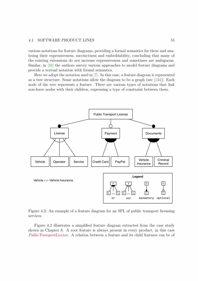
4.1. SOFTWARE PRODUCT LINES 55
various notations for feature diagrams, providing a formal semantics for these and ana-lysing their expressiveness, succinctness and embeddability, concluding that many ofthe existing extensions do not increase expressiveness and sometimes are ambiguous.Similar, in [34] the authors survey various approaches to model feature diagrams andprovide a textual notation with formal semantics.
Here we adopt the notation used in [7]. In this case, a feature diagram is representedas a tree structure. Some notations allow the diagram to be a graph (see [134]). Eachnode of the tree represents a feature. There are various types of notations that linknon-leave nodes with their children, expressing a type of constraint between them.
Public Transport License
License Documents
Vehicle Operator Service Vehicle Insurance
Criminal Record
Payment
Credit Card PayPal
Vehicle <-> Vehicle Insurance
…
P
C1 Cn …
P
C1 Cn
P
C
P
C
Legend
or xor optionalmandatory
Figure 4.2: An example of a feature diagram for an SPL of public transport licensingservices.
Figure 4.2 illustrates a simplified feature diagram extracted from the case studyshown in Chapter 8. A root feature is always present in every product, in this casePublicTransportLicense. A relation between a feature and its child features can be of

56 CHAPTER 4. TECHNICAL BACKGROUND
four types as described by the legend: or – some out of many can be selected; xor – oneout of many can be selected; mandatory – always present; and optional – optionallypresent. For example, a feature License must always be selected, specifying only onetype of license, Vehicle, transport Operator , or Service. Not all public transport li-censes require Payment support, and if they do, they could support payments throughCreditCard , PayPal , or both. In addition, a feature can be selected only if its parentfeature is selected. Because not all constraints can be expressed in a tree structure,additional cross-tree constraints can be added in textual form using propositional lo-gic. In the example, support for VehicleInsurance documentation can be selected, ifand only if, the selected license to be derived is a license for Vehicles to transportpassengers.
As mentioned, there are many variants of feature diagrams, some distinguish betweenconcrete and abstract features, where an abstract feature do not have associated assets,others allow multi-features [48], i.e. to select a feature multiple times, each time withdifferent child configurations. A comprehensive analysis of feature diagrams can befound in [134].
Formal feature models
The simplest way to give a formal semantics to feature diagrams is to translate theminto propositional logic where each feature is treated as a boolean variable. Examplesof this approaches can be seen in [7, 23,110].
Given a feature diagram over a set of features F , we can obtain a formal featuremodel in propositional logic applying the following set of rules to each edge of thefeature diagram [7]:
root(P ) ≡ P
mandatory(P ,C ) ≡ P ↔ C
optional(P ,C ) ≡ C → P
or(P , C1 , . . . ,Cn) ≡ P ↔ (C1 ∨ C2 ∨ · · · ∨ Cn)
xor(P , C1 , . . . ,Cn) ≡ P ↔ (C1 ∨ · · · ∨ Cn) ∧∧i≤j
¬(Ci ∧ Cj )
The resulting future model in propositional logic is the conjunction of formulas obtainedby applying such rules. In addition, since cross-tree constraints can be added in textualform to the feature diagram, these are as well conjoined in the resulting model.
For example, the feature diagram shown in Figure 4.2 can be translated into the
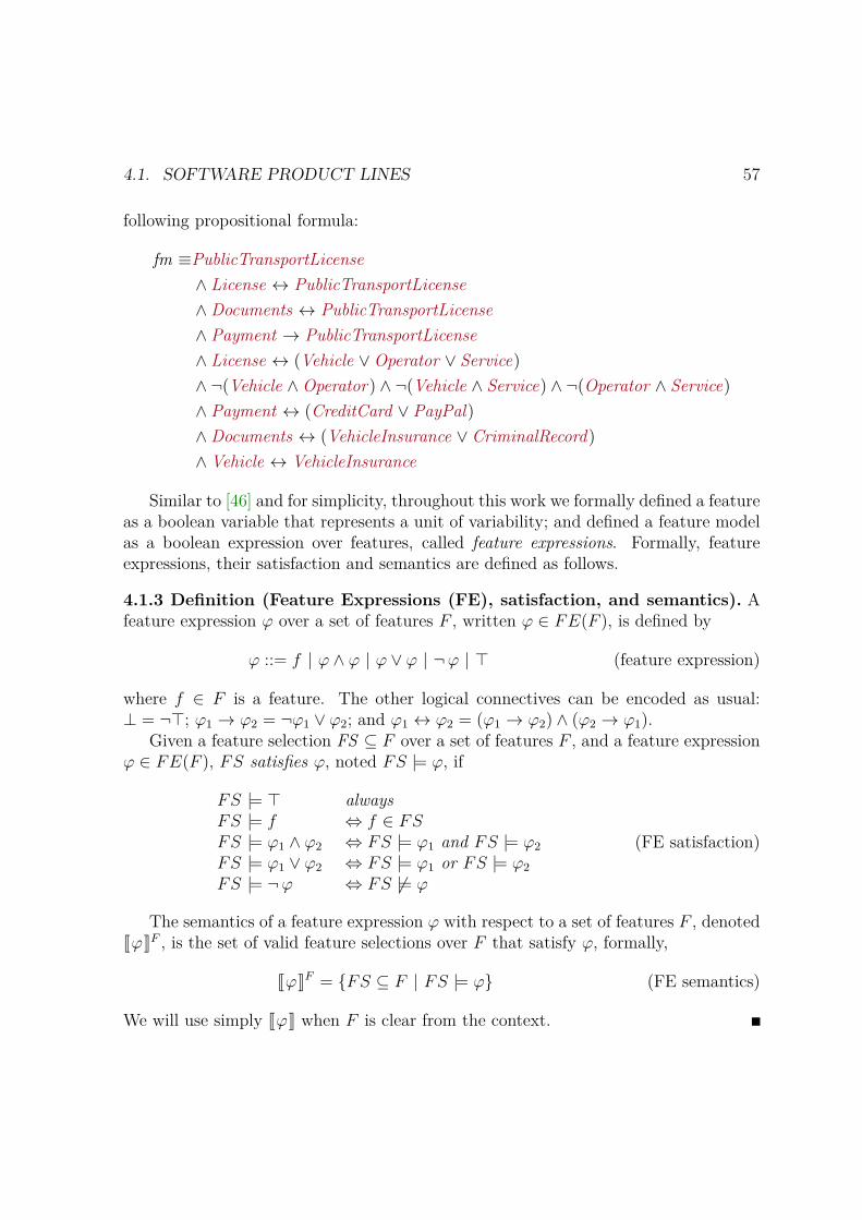
4.1. SOFTWARE PRODUCT LINES 57
following propositional formula:
fm ≡PublicTransportLicense
∧ License ↔ PublicTransportLicense
∧ Documents ↔ PublicTransportLicense
∧ Payment → PublicTransportLicense
∧ License ↔ (Vehicle ∨Operator ∨ Service)
∧ ¬(Vehicle ∧Operator) ∧ ¬(Vehicle ∧ Service) ∧ ¬(Operator ∧ Service)
∧ Payment ↔ (CreditCard ∨ PayPal)
∧ Documents ↔ (VehicleInsurance ∨ CriminalRecord)
∧ Vehicle ↔ VehicleInsurance
Similar to [46] and for simplicity, throughout this work we formally defined a featureas a boolean variable that represents a unit of variability; and defined a feature modelas a boolean expression over features, called feature expressions. Formally, featureexpressions, their satisfaction and semantics are defined as follows.
4.1.3 Definition (Feature Expressions (FE), satisfaction, and semantics). Afeature expression φ over a set of features F , written φ ∈ FE(F ), is defined by
φ ::= f | φ ∧ φ | φ ∨ φ | ¬φ | ⊤ (feature expression)
where f ∈ F is a feature. The other logical connectives can be encoded as usual:⊥ = ¬⊤; φ1 → φ2 = ¬φ1 ∨ φ2; and φ1 ↔ φ2 = (φ1 → φ2) ∧ (φ2 → φ1).
Given a feature selection FS ⊆ F over a set of features F , and a feature expressionφ ∈ FE(F ), FS satisfies φ, noted FS |= φ, if
FS |= ⊤ alwaysFS |= f ⇔ f ∈ FSFS |= φ1 ∧ φ2 ⇔ FS |= φ1 and FS |= φ2
FS |= φ1 ∨ φ2 ⇔ FS |= φ1 or FS |= φ2
FS |= ¬φ ⇔ FS |= φ
(FE satisfaction)
The semantics of a feature expression φ with respect to a set of features F , denotedJφKF , is the set of valid feature selections over F that satisfy φ, formally,
JφKF = FS ⊆ F | FS |= φ (FE semantics)
We will use simply JφK when F is clear from the context.
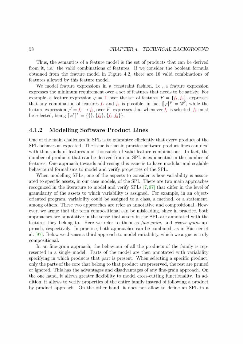
58 CHAPTER 4. TECHNICAL BACKGROUND
Thus, the semantics of a feature model is the set of products that can be derivedfrom it, i.e. the valid combinations of features. If we consider the boolean formulaobtained from the feature model in Figure 4.2, there are 16 valid combinations offeatures allowed by this feature model.
We model feature expressions in a constraint fashion, i.e., a feature expressionexpresses the minimum requirement over a set of features that needs to be satisfy. Forexample, a feature expression φ = ⊤ over the set of features F = f1 , f2, expressesthat any combination of features f1 and f2 is possible, in fact JφKF = 2F , while thefeature expression φ′ = f1 → f2 , over F , expresses that whenever f1 is selected, f2 mustbe selected, being Jφ′KF = , f2, f1 , f2.
4.1.2 Modelling Software Product LinesOne of the main challenges in SPL is to guarantee efficiently that every product of theSPL behaves as expected. The issue is that in practice software product lines can dealwith thousands of features and thousands of valid feature combinations. In fact, thenumber of products that can be derived from an SPL is exponential in the number offeatures. One approach towards addressing this issue is to have modular and scalablebehavioural formalisms to model and verify properties of the SPL.
When modelling SPLs, one of the aspects to consider is how variability is associ-ated to specific assets, in our case models, of the SPL. There are two main approachesrecognized in the literature to model and verify SPLs [7, 97] that differ in the level ofgranularity of the assets to which variability is assigned. For example, in an object-oriented program, variability could be assigned to a class, a method, or a statement,among others. These two approaches are refer as annotative and compositional. How-ever, we argue that the term compositional can be misleading, since in practice, bothapproaches are annotative in the sense that assets in the SPL are annotated with thefeatures they belong to. Here we refer to them as fine-grain, and coarse-grain ap-proach, respectively. In practice, both approaches can be combined, as in Kästner etal. [97]. Below we discuss a third approach to model variability, which we argue is trulycompositional.
In an fine-grain approach, the behaviour of all the products of the family is rep-resented in a single model. Parts of the model are then annotated with variabilityspecifying in which products that part is present. When selecting a specific product,only the parts of the core that belong to that product are preserved, the rest are prunedor ignored. This has the advantages and disadvantages of any fine-grain approach. Onthe one hand, it allows greater flexibility to model cross-cutting functionality. In ad-dition, it allows to verify properties of the entire family instead of following a productby product approach. On the other hand, it does not allow to define an SPL in a
4.1. SOFTWARE PRODUCT LINES 59
modularized way. The core asset can quickly grow in complexity, which hinders theunderstanding, maintainability, and evolution of the SPL. Examples of fine-grain be-havioural formalisms found in the literature include the use of transition systems andfinite automata [35,47], where transitions are annotated with a feature expression, sim-ilar to how feature expressions are defined here. In both cases, a single model is builtcontaining the behaviour of the entire family. Model checking techniques are later usedto verify properties over the entire model.
In a coarse-grain approach, the modelling and reasoning of features is done in isol-ation. The SPL is design in a modularized way, where functionality is divided intocomposable units, where each unit typically corresponds to a feature. Each featurespecifies how it alters the core model. When selecting a specific product, only com-ponents that correspond to a selected feature are composed into the final product. Itcan be verify if a given combination of features preserves the properties of the indi-vidual ones, but requires to check over every possible combination of features. It hasbeen proposed [8] to model features in a compositional manner but to model checkthem following an fine-grain approach. The advantage of the coarse-grain approachis that variability and functionality are encapsulated in composable units, simplifyingthe design, and addressing the main issues of the fine-grain approach. Of course, themain disadvantage is that it is not always possible to decompose variability into well-defined components, as in the case of cross-cutting functionality. Typical examples ofthis approach can be found at the level of implementation [22, 97], where features canextend a class by redefining methods or adding new ones.
From the literature, we would like to recognize a third approach, a truly compos-itional approach. In this approach, an SPL can be designed following a component-based approach in which functionality is divided into simpler components, each ofwhich can be annotated with variability. In addition, each component possess its ownfeature model. The SPL can then be built by composing the components, includingtheir variability models. An example of a behavioural formalism following this ap-proach includes an extension to Petri Nets, where each net has a feature model, andarcs in the net can be annotated with features indicating in which products the arcsare present [115]. Various nets can be combined through composition, where featuremodels from separately engineered models of individual features are composed as well.
In the coarse-grain approach, only components that belong to selected featuresare combined in the final product. In this sense, this approach composes products.In the truly compositional one, the entire SPL is composed out of smaller variablecomponents. In this sense, this approach composes SPLs, or families of products.This provides some advantages over only fine-grain or coarse-grain approaches. First,it gathers the best of both approaches: modularization while having the ability toassign variability at a finer level. Second, it allows to model variable components
60 CHAPTER 4. TECHNICAL BACKGROUND
with independent variability models, composed them together and reason about thecomposed variability model, what products can be derived, and dependencies betweenfeatures, among others. Thus, in this work we focus on the compositional approachand propose accordingly a compositional formalism to model SPLs in Chapter 5.
4.1.3 SPLs and Digital GovernmentOnly a few studies can be found in the literature regarding SPL support for the devel-opment of digital government applications. In [107], the authors propose an SPL forgenerating front-end environments for an e-government context management system.In [125], the authors propose a method to generate personalized government documentsusing SPL. The approach takes advantage of the high level reuse of government docu-ments. More recently, SPLs have been used to support the development of personalizedapplications in smart cities [105].
Although not yet widely used in government, the concept of SPL offers unique op-portunities for the rapid development and deployment of certain services provided bylocal governments. For example, following our case study, in most public administra-tion systems, local governments are responsible for issuing licenses for public transportservices. While such services comprise a number of common functionality – e.g. sub-mission and approval of the public transport route, submission and approval of thevehicles certificates of property, submission and approval of the drivers’ driving li-censes, etc.; they also differ in a number of features, mostly due to specific regulationsof each local government. Therefore, the idea of applying SPL for generating a familyof certain type of public services is appealing and relevant to the public sector.
However, in addition to the concept, there is a need to provide appropriate tools tofacilitate the generation of reliable software systems supporting the delivery of publicservices based on the SPL concept. In this sense, the use of formal methods andSPLs can help to overcome this issue and, to some extent, the challenges described inSection 2.2. On the one hand, formal methods help to model and verify that servicesconform with the required laws and regulations at an early stage. On the other hand,software product lines can help to rapidly develop families of services, reducing costsand development efforts, as well as facilitating service integration. Thus, it offers uniqueopportunities for the rapid development and deployment of certain services providedby local governments.
Thus, integrating both approaches seems the way to go. Various formalisms andapproaches exist to formally model and verify SPLs as mentioned in Section 4.1.2.However, they are mainly fine-grain or coarse-grain approaches. Following a compos-itional approach to formally model SPLs seems more interesting due to its flexibilityand potential improvement over the other approaches.

4.2. FEATURED TIMED AUTOMATA 61
In addition, based on our case study we recognize that time constraints, althoughnot necessarily real-time constraints, are a recurrent requirement in government ser-vices. Thus, we focus in a formalism capable of capturing this requirements. Fromthe literature, Featured Timed Automata is a very interesting formalism with efficientalgorithms to verify properties over the models. However, it is a fine-grain approach,and as such it does not allow to model SPLs in a compositional way. Thus, the com-positional formalism proposed in Chapter 5 is based on this formalism. We providethe necessary background on Featured Timed Automata in the following section.
4.2 Featured Timed AutomataFeatured Timed Automata (FTA), introduced by Cordy et al. [47], is an extension toTimed Automata (TA) [4] to model and verify families of real-time systems paramet-rized by a variability model. This parametrization enables to model various systems ina single model, simplifying the design and improving efficiency during model checking.
Essentially, FTA extends TA by incorporating a set of features, which representunits of variability, and a feature model, which determines the set of valid featurecombinations. Each valid combination determines a concrete product in the family,i.e., a timed system modelled as a timed automata.
We first introduce some preliminary notions of Timed Automata in Section 4.2.1.Then, in Section 4.2.2 we present the formal definition of a featured timed automatonand its semantics based on Cordy et al..
4.2.1 Timed SystemsFeatured Timed Automata builds on top of Timed Automata, introduced by Alur etal. in [4] as an abstract model for timed systems. A timed automaton is a finiteautomaton equipped with a finite set of real-valued variables representing a set ofclocks, and logic guards over clocks, called clock constraints, to model time constraintsabout the behavior of the system.
A clock c is a logical entity that models continue and dense-time. It can only beinspected or reset to zero, and represents the time elapsed since its last reset. When atimed automaton evolves over time, all clocks are incremented simultaneously. Initially,all clocks are reset to zero.
Clock constraints are logic conditions over the value of a clock. They are used aslogic guards to represent time constraints over locations, restricting the amount of timethe system can spend in the location; and over transitions, restricting when the systemcan move to another location by taking an action on a transition. Specifically, clock

62 CHAPTER 4. TECHNICAL BACKGROUND
constraints over locations are called location invariants.Intuitively, a TA may remain in a location as long as the current clock valuation,
i.e., the current value of the clocks, satisfies the invariant of the location; and mayleave a location by taking an outgoing transition, only while the current clock valuationsatisfies the clock constraint of the transition. Notice that transitions are instantaneoussteps, i.e., taking a transition does not increment the value of the clocks. We illustratethis with an example before presenting any formal definition.
4.2.1 Example. Figure 4.3 shows a timed automaton modelling a payment selec-tion controller. There are two locations, ℓ0 and ℓ1, a clock c , and three actionspay , creditcard and paypal , representing the ability to pay, and to select the paymentmethod, i.e., credit card or PayPal, respectively. Initially the automaton is in locationℓ0, indicated by a node with double line 1, and it can evolve either by waiting fortime to pass, incrementing the clock c, or by taking the transition to ℓ1. Taking suchtransition triggers the reset of the clock c back to 0, evolving to the state ℓ1. Here itcan wait for the time to pass, but for at most 5 time units, determined by the invariantc ≤ 5 in ℓ1. In location ℓ1 it can either evolve by selecting to pay by PayPal or bycredit card. However, these transitions have a different guard: a clock constraint c ≥ 1that allows the transitions to be taken only when clock c is greater than 1. ◁
ℓ0 ℓ1
[c ≤ 5 ]paypalc ≥ 1
payc := 0
creditcardc ≥ 1
Figure 4.3: An example of a TA modelling a payment selection controller.
We now present the formal definition of clock constraints and timed automata.
4.2.1 Definition (Clock Constraints (CC), valuation, and satisfaction). Aclock constraint over a set of clocks C, written g ∈ CC(C) is defined by
g ::= c < n | c ≤ n | c = n | c > n | c ≥ n | g ∧ g | ⊤ (clock constraint)
where c ∈ C, and n ∈ N.1This notation is adopted as well by Uppaal. It can be confusing since in Büchi Automata a
double line indicates accepting states, which are used to reason about the progress of the system.However, when dealing with Timed Safety Automata, as in this case, the notion of progress is givenby invariants associated to locations instead of accepting states [25].

4.2. FEATURED TIMED AUTOMATA 63
A clock valuation η for a set of clocks C is a function η : C → R≥0 that assigns eachclock c ∈ C to its current value ηc. We use RC to refer to the set of all clock valuationsover a set of clocks C. Let η0(c) = 0 for all c ∈ C be the initial clock valuation thatsets to 0 all clocks in C. We use η + d, d ∈ R≥0, to denote the clock assignment thatmaps all c ∈ C to η(c)+d, and let [r 7→ 0]η, r ⊆ C, be the clock assignment that mapsall clocks in r to 0 and agrees with η for all other clocks in C \ r.
The satisfaction of a clock constraint g by a clock valuation η, written η |= g, isdefined as follows
η |= ⊤ alwaysη |= c n if η(c) nη |= g1 ∧ g2 if η |= g1 and η |= g2
(clock satisfaction)
where ∈ <,≤,=, >,≥.
4.2.2 Definition (Timed Automata (TA)). A timed automaton is a tuple A =(L, ℓ0, A, C, T, Inv), where:
– L is a finite set of locations,
– ℓ0 is the initial location,
– A is a finite set of labels representing actions,
– C is a finite set of clocks,
– T ⊆ L× CC(C)× A× 2C × L is a finite set of transitions
– Inv : L → CC(C) is a function assigning invariants to locations.
In a transition (l, g, a, r, l′) ∈ T , sometimes written ℓg,a,r−−−→A ℓ′, l is the origin location,
g is the clock constraint or guard associated to the transition, a is the action triggeringthe transition, r is the set of clocks to reset, and l′ is the target location.
Notation. 2A denotes the powerset of A. Given any automaton A, we use LA, ℓ0A ,AA, . . . to refer to the elements of A when not clear from the context.
The semantic representation of a TA is given by a Labelled Transition System orjust Transition System (TS) [16]. Figure 4.4 illustrates the infinite transition systemcorresponding to the TA of the payment controller shown in Figure 4.3. The statesof the underlying TS of a TA A consist of a location of A and a clock valuation thatrepresents the current value of the clocks in that state. The transitions between states

64 CHAPTER 4. TECHNICAL BACKGROUND
of the TS can be delay transitions, e.g., ⟨ℓ0, c = 0⟩ 2−→ ⟨ℓ0, c = 2⟩, or action transitions,
e.g., ⟨ℓ0, c = 0⟩ pay−−→ ⟨ℓ1, c = 0⟩. Delay transitions model the passing of time, i.e., theymodel when A does not take any action, staying in the same location but incrementingthe value of the clocks. Action transitions model when A takes an action on an actualtransition, moving to a possible new location and without altering the value of theclocks, except for those that are reset to 0 by the transition.
⟨ℓ0, c = 0⟩ ⟨ℓ1, c = 0⟩
⟨ℓ0, c = 2⟩ . . .
. . .
...
⟨ℓ1, c = 2⟩. . . . . .pay
pay
2 paypal
Figure 4.4: An illustration of an infinite TS corresponding to the TA in Figure 4.3.
4.2.3 Definition (Semantics of TA). The semantics of a timed automaton A =(L, ℓ0, A, C, T, Inv), is a transition system JAK = (St, s0, A, T
′), where:
– St = L × RC is the set of states, consisting of the current location and clockvaluation,
– s0 = ⟨ℓ0, η0⟩ is the initial state, and
– T ′ ⊆ St× (A ⊎ R≥0)× St is the transition relation, defined as follows
⟨ℓ, η⟩ d−→ ⟨ℓ, η + d⟩ if η |= Inv(ℓ) and (η + d) |= Inv(ℓ), for d ∈ R≥0 (4.1)
⟨ℓ, η⟩ a−→ ⟨ℓ′, η′⟩ if ∃ ℓg,a,r−−−→ ℓ′ ∈ T s.t. η |= g,
η |= Inv(l), η′ = [r 7→ 0]η, and η′ |= Inv(ℓ′) (4.2)
Condition (4.1) defines delay transitions. A delay transition is labelled with apositive delay d ∈ R≥0. For a delay transition to exist, the clock valuation of the originstate, η, must satisfy the invariant of the location ℓ; while the updated clock valuationafter taking the delay transition, η+d, must still satisfied the invariant of such location.Condition (4.2) defines action transitions. The transition is labelled with the actionof the corresponding transition in A. For an action transition to exists between two
4.2. FEATURED TIMED AUTOMATA 65
states, the clock valuation of the origin state, η, must satisfy the invariant of the originlocation, ℓ, and the guard, g, associated to the transition; while the clock valuation ofthe target state, defined as η for all clocks, except for clocks in r which are reset to 0,must satisfy the invariant of the target location, ℓ′.
Multiple TA can be composed in parallel to model concurrent systems, resultingin a network of Timed Automata. Parallel composition of TA reduces to computingthe product of the automata, where the automata in the network may interleave ortransition together through the use of shared actions, called synchronization actions.In a network there are no external actions, i.e., all actions are synchronized and thenetwork is considered a closed system. The formal definition of a network of TA andits semantics can be found in [25]. In practice, computing the product of a network ofautomata is computationally expensive, however, it can be computed on-the-fly as isin the case of the real-time model checker Uppaal.
4.2.2 Families of Timed SystemsFeatured Timed Automata is an fine-grain approach introduced by Cordy et al., [47]to model real-time SPL. Thus, an FTA encodes in a single model various modelscorresponding to a family of timed systems, in particular, each model being a concretetimed automaton. Given a FTA, it is possible to model check it against a givenproperty expressed in Timed Computation Tree Logic (TCTL) [16] and determine theset of products that satisfy or violate such a property.
In order to model a family of timed automata in a single model, FTA extends TAwith features, feature expressions, and a feature model. As mentioned in Section 4.1.1,features represent units of variability supported by the model, and are modelled asa set of Boolean variables. Feature expressions are Boolean conditions over features,and are associated to transitions to specify the set of concrete products of the SPL (inthis case, concrete TA) where a given transition is present. The feature model, heremodelled as a feature expression, represents the set of valid feature combinations, i.e.,the set of concrete products that can be derived from the model.
We can now present the formal definition of FTA based on Cordy et al.. For thesake of simplicity, we have slightly modify the original definition. In particular, we usean unique initial location instead of a set of locations; we use clock constraints insteadof featured clock constraints (clocks constraints parametrized by features expressions);and we do not associate atomic propositions to locations. In the last case, this isbecause FTA uses a state-based approach to verify properties of a family, where theobservable behaviour of an FTA is given by a set of properties, usually called atomicpropositions, associated to the current state of the system. However, we use an action-based approach, since we focus on modelling interactive systems where the observable
66 CHAPTER 4. TECHNICAL BACKGROUND
behaviour is rather given by the actions available through outgoing transitions fromthe current state.
4.2.4 Definition (Featured Timed Automata (FTA) [47]). A featured timedautomaton is a tuple A = (L, l0, A, C, T, Inv , F, fm, γ) where L, ℓ0,A, C, T , and Invare defined as in TA (Definition 4.2.2), and F, fm, and γ are defined as follows:
– F is a finite set of features,
– fm ∈ FE (F ) is a feature model defined as a FE over features in F , and
– γ : T → FE (F ) is a total function that assigns feature expressions to edges.Sometimes we shall write l
g,a,r−−−→φ
l′ to express that γ(l, g, a, r, l′) = φ and that(l, g, a, r, l′) ∈ T .
Now we can encode various models of similar systems into a single FTA by takenadvantage of their similarities. Let us consider the payment controller introduced inFigure 4.3. Imagine we now want to model an SPL of payment controllers to capturesystems with support for different payment methods: a) only credit card, b) onlyPayPal, and c) both. We can easily do this by representing the support for eachmethod as features supported by the SPL. Figure 4.5 (top left) depicts such a FTA.The model is further explained in Example 4.2.2.
4.2.2 Example (FTA). Figure 4.5 exemplifies a simple FTA modeling an SPL ofpayment selection controllers. The base model corresponds to the TA depicted inFigure 4.3 and it is parameterized by two features pp and cc, standing for the supportfor paying by PayPal and by credit card, respectively. The transitions labelled with theaction paypal and creditcard are only active when the corresponding feature is present,while the transition labelled with the action pay is active if at least one of the paymentmethods is present. The lower expression [ fm = pp ∨ cc ] defines the feature model,i.e., how the features relate to each other. In this case at least one payment methodmust be supported. ◁
By selecting a desired combination of features, one can map an FTA into a concreteTA. Figure 4.5 (top right, and bottom) depicts the resulting TA obtained by projectingthe payment controller into its three valid feature selections. The formal definition ofprojection follows. This definition has been slightly adapted from [47] to reflect thechanges introduced in our modified definition of FTA.
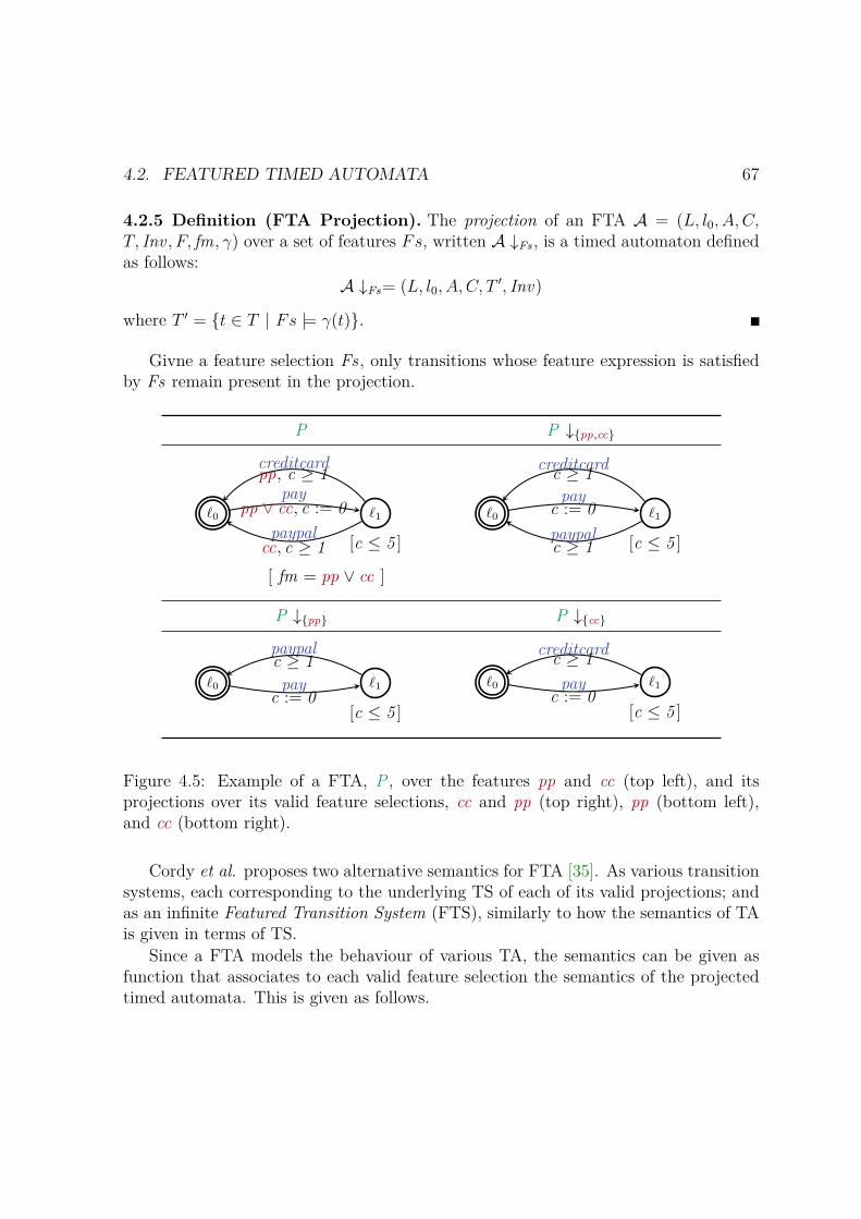
4.2. FEATURED TIMED AUTOMATA 67
4.2.5 Definition (FTA Projection). The projection of an FTA A = (L, l0, A, C,T, Inv , F, fm, γ) over a set of features Fs, written A ↓Fs , is a timed automaton definedas follows:
A ↓Fs= (L, l0, A, C, T′, Inv)
where T ′ = t ∈ T | Fs |= γ(t).
Givne a feature selection Fs , only transitions whose feature expression is satisfiedby Fs remain present in the projection.
P P ↓pp,cc
ℓ0 ℓ1
[c ≤ 5 ]paypal
cc, c ≥ 1
paypp ∨ cc, c := 0
creditcardpp, c ≥ 1
[ fm = pp ∨ cc ]
ℓ0 ℓ1
[c ≤ 5 ]paypalc ≥ 1
payc := 0
creditcardc ≥ 1
P ↓pp P ↓cc
ℓ0 ℓ1
[c ≤ 5 ]
paypalc ≥ 1
payc := 0
ℓ0 ℓ1
[c ≤ 5 ]
payc := 0
creditcardc ≥ 1
Figure 4.5: Example of a FTA, P , over the features pp and cc (top left), and itsprojections over its valid feature selections, cc and pp (top right), pp (bottom left),and cc (bottom right).
Cordy et al. proposes two alternative semantics for FTA [35]. As various transitionsystems, each corresponding to the underlying TS of each of its valid projections; andas an infinite Featured Transition System (FTS), similarly to how the semantics of TAis given in terms of TS.
Since a FTA models the behaviour of various TA, the semantics can be given asfunction that associates to each valid feature selection the semantics of the projectedtimed automata. This is given as follows.

68 CHAPTER 4. TECHNICAL BACKGROUND
4.2.6 Definition (Semantics of FTA in terms of TS). The semantics of featuredtimed automaton A = (L, l0, A, C, T, Inv , F, fm, γ), is a function JAK such that:
∀ Fs ∈ Jfm KF · JAK(Fs) = JA ↓Fs KAlternatively, the semantics can be given in terms of FTS. An FTS extends Trans-
ition Systems with a set of features F , a feature model fm, and a total function γ thatassigns FE to transitions. The formal definition of semantics of an FTA as an FTSfollows. Notice that this definition of semantics has been adapted to incorporate themodifications over FTA adopted here, namely, no featured clock constraints and noapplication conditions.
4.2.7 Definition (Semantics of FTA as an FTS). The semantics of a featuredtimed automaton A = (L, l0, A, C,E, Inv , F, fm, γ), is a featured transition systemJAK = (St, s0, A, T, F, fm, γ′), where:
– St ⊆ L × RC is the set of states consisting of the current location and clockvaluation,
– s0 = ⟨ℓ0, η0⟩ is the initial state,
– T ⊆ St × (A ⊎ R≥0)× St is the transition relation, sometimes written s1α−→ s2
to express that (s1, α, s2) ∈ T , and
– γ′ : T → FE(F ) is a total function that assigns feature expressions to transitionsin T , sometimes written s1
α−→φ
s2 to express that γ(s1, α, s2) = φ for (s1, α, s2) ∈T .
The transition relation and γ are defined as follows, based on A:
⟨ℓ, η⟩ d−→⊤
⟨ℓ, η + d⟩ if η |= Inv(ℓ) and (η + d) |= Inv(ℓ), for d ∈ R≥0 (4.3)
⟨ℓ, η⟩ a−→φ
⟨ℓ′, η′⟩ if ∃ ℓg,a,r−−−→φ
ℓ′ ∈ E s.t. η |= g, η |= Inv(l),
η′ = [r 7→ 0]η, and η′ |= Inv(ℓ′) (4.4)
Transitions in the resulting FTS are defined similarly to how transitions are definedfor the underlying transition system of a TA (Definition 4.2.3). The main difference

4.3. REO COORDINATION LANGUAGE 69
is that now transitions are associated with a feature expression that determines theproducts (concrete TS) in which such transitions are present. Since delay transitions areindependent from the variability, i.e., they depend only on the current clock valuationand on the invariant associated to the origin and target location, they are present inevery product. Thus, their feature expression is always true (⊤). The feature expressionassociated to an action transition, is simply the feature expression of the transition itrepresents in the corresponding FTA A.
These alternative definitions of semantics enable two different ways to model checkFTA: following a product by product approach, by analysing the underlying transitionsystem of each TA projected; and following a variability aware approach that verifiesproperties over the entire family at once. The main characteristic of the second ap-proach is that it takes advantage of the common behaviour of the various productsin the family during verification, which can reduce significantly verification times. Ofcourse, this might not be the case always, since in the case of very large SPLs it mightbe more efficient to take advantage of parallel processors to verify in parallel propertiesof different products or subsets of products of the SPL.
4.3 Reo Coordination LanguageCoordination of interacting and concurrent components can be done endogenously, orexogenously [9, 10]. In endogenous coordination, coordination is treated as a second-class concept, and it appears intertwine within the models of the components’ computa-tion. This hinders the study of properties of the components behaviour and the coordin-ation protocol, as well as their maintainability and scalability. Examples of endogenouscoordination includes: process algebras, share memory, and message passing, amongothers. In exogenous coordination, coordination is treated as a first-class concept,where the models of coordination protocols reside separately from the componentsthey orchestrate. This facilitates anonymous communication of components, i.e., com-ponents have no knowledge of other components nor of the coordination protocols.Thus, it is possible to yield loosely-coupled and flexible systems whose componentsand coordination protocols can be easily study, maintain, and scale up. Examples ofexogenous coordination include Reo and to some extent, Orc [98].
Given that the nature of software product lines is to derive products from a commonset of assets, including models, one would expect to maximize as much as possible(without hindering productivity) the reusability of such models. One step towards suchdirection is to take advantage of exogenous coordination to increase the reusability ofboth, the coordination protocols and the components, which are oblivious to othercomponents and how they interact with each other.

70 CHAPTER 4. TECHNICAL BACKGROUND
Towards this goal, we focus on Reo, a well known channel-based exogenous coordin-ation language, introduced by Arbab [9], in order to understand exogenous coordinationand how we can use this concept to model variable coordination protocols to coordinatefamilies of services/components.
The language is based on the notion of channel composition [9]. In Reo, complexcoordinators, called connectors, are compositionally built out of simpler ones, calledchannels. Each channel has a set of input and output ports, and a well defined semanticsof how data flows from the inputs to the outputs. Channels can be composed byconnecting their ends through nodes.
These connectors can then be used to orchestrate how components in a component-based system interact. Since Reo is simply a coordination formalism, it abstractsfrom what a component can be (models, processes, threads, etc.). Instead, it assumesthat components have a set of input and output ports, such that an input port of acomponent can read from the output port of a connector to which it is connected to;while an output port of a component can write out data items into the input port of aconnector to which it is connected to. Components themselves can be a connector orencapsulate various simpler components orchestrated through Reo connectors.
4.3.1 Primitive ChannelsA channel consists of two ends and a constraint of how data flows through those ends.Channel ends can be of two types, input and output. An input end accepts datainto its channel, and an output end dispenses data out of its channel. Each channelhas associated an intuitive graphical notation that hints on how data flows throughchannels ends. As a consequence, it aids in the understanding of connectors, whosesemantics is revealed by the resulting composed graphical notation.
In the most basic notion of Reo, constraints that specify the behaviour of a chan-nel can be classified into synchronisation constraints and dataflow constraints. A syn-chronization constraint describes how the ends are synchronized on a particular step.Typically, it describes the atomicity, exclusion, order, and/or timing of the passage ofdata. For example, synchronous channels allow data to flow on both ends or neitherend, while asynchronous channels allow data to flow on at most one of their ends. Adataflow constraint specifies constraints on the data that flows through the channel.Typically, it describes the content, the conditions for loss, and/or creation of data thatpasses through the ends of a channel. For example, a channel may specify that thedata that flow through the input end must be exactly the same data that flows throughthe output end.
Channels are user defined, however there are a set of basic channels that can beused to built significantly complex connectors. We describe some of these channels
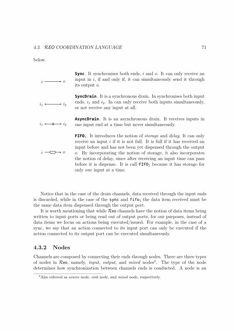
4.3. REO COORDINATION LANGUAGE 71
below.
i o
Sync. It synchronises both ends, i and o. It can only receive aninput in i, if and only if, it can simultaneously send it throughits output o.
i1 i2
SyncDrain. It is a synchronous drain. In synchronises both inputends, i1 and i2. In can only receive both inputs simultaneously,or not receive any input at all.
i1 i2AsyncDrain. It is an asynchronous drain. It receives inputs inone input end at a time but never simultaneously.
i o
FIFO1. It introduces the notion of storage and delay. It can onlyreceive an input i if it is not full. It is full if it has received aninput before and has not been yet dispensed through the outputo. By incorporating the notion of storage, it also incorporatesthe notion of delay, since after receiving an input time can passbefore it is dispense. It is call FIFO1 because it has storage foronly one input at a time.
Notice that in the case of the drain channels, data received through the input endsis discarded, while in the case of the sync and fifo1 the data item received must bethe same data item dispensed through the output port.
It is worth mentioning that while Reo channels have the notion of data items beingwritten to input ports or being read out of output ports, for our purposes, instead ofdata items we focus on actions being executed/issued. For example, in the case of async, we say that an action connected to its input port can only be executed if theaction connected to its output port can be executed simultaneously.
4.3.2 NodesChannels are composed by connecting their ends through nodes. There are three typesof nodes in Reo, namely, input, output, and mixed nodes2. The type of the nodedetermines how synchronization between channels ends is conducted. A node is an
2Also referred as source node, sink node, and mixed node, respectively.
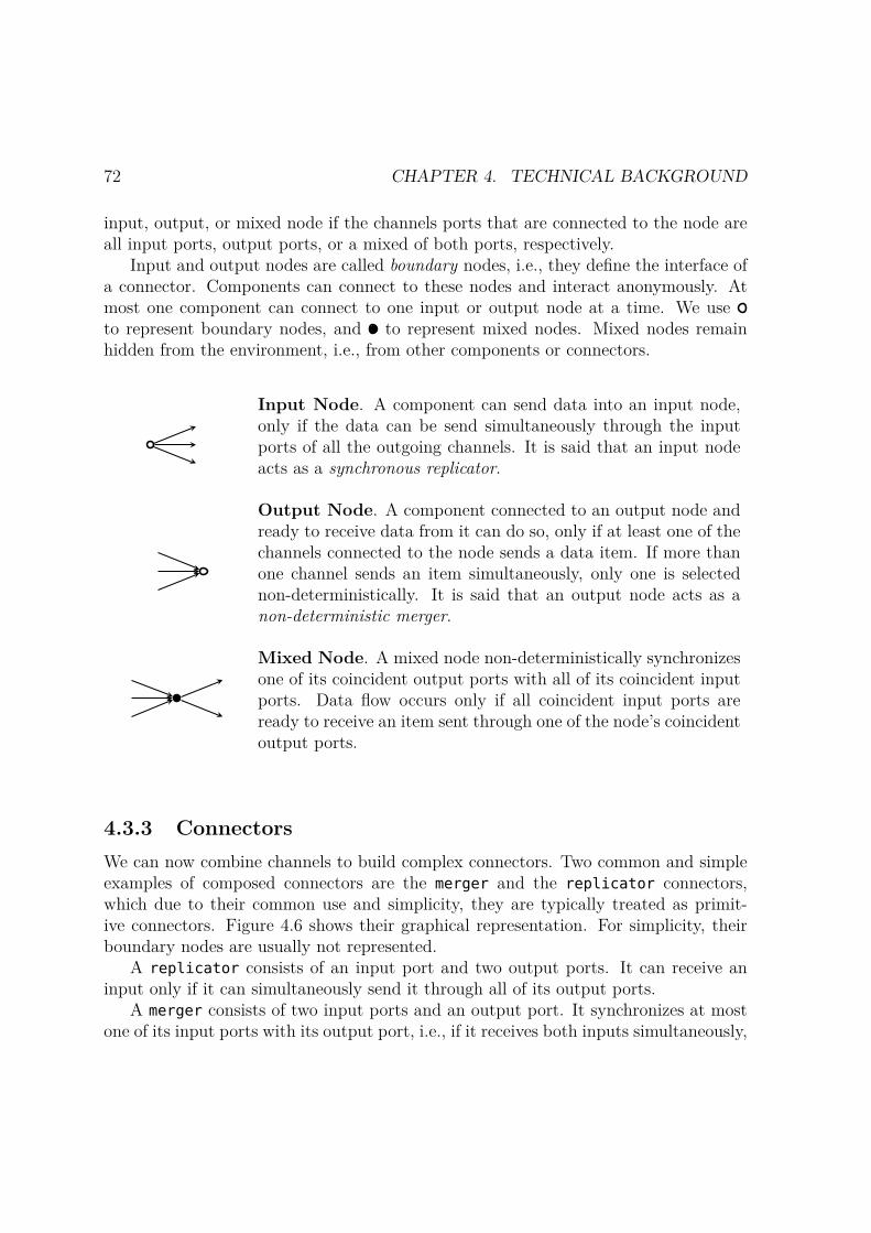
72 CHAPTER 4. TECHNICAL BACKGROUND
input, output, or mixed node if the channels ports that are connected to the node areall input ports, output ports, or a mixed of both ports, respectively.
Input and output nodes are called boundary nodes, i.e., they define the interface ofa connector. Components can connect to these nodes and interact anonymously. Atmost one component can connect to one input or output node at a time. We useto represent boundary nodes, and to represent mixed nodes. Mixed nodes remainhidden from the environment, i.e., from other components or connectors.
Input Node. A component can send data into an input node,only if the data can be send simultaneously through the inputports of all the outgoing channels. It is said that an input nodeacts as a synchronous replicator.
Output Node. A component connected to an output node andready to receive data from it can do so, only if at least one of thechannels connected to the node sends a data item. If more thanone channel sends an item simultaneously, only one is selectednon-deterministically. It is said that an output node acts as anon-deterministic merger.
Mixed Node. A mixed node non-deterministically synchronizesone of its coincident output ports with all of its coincident inputports. Data flow occurs only if all coincident input ports areready to receive an item sent through one of the node’s coincidentoutput ports.
4.3.3 ConnectorsWe can now combine channels to build complex connectors. Two common and simpleexamples of composed connectors are the merger and the replicator connectors,which due to their common use and simplicity, they are typically treated as primit-ive connectors. Figure 4.6 shows their graphical representation. For simplicity, theirboundary nodes are usually not represented.
A replicator consists of an input port and two output ports. It can receive aninput only if it can simultaneously send it through all of its output ports.
A merger consists of two input ports and an output port. It synchronizes at mostone of its input ports with its output port, i.e., if it receives both inputs simultaneously,

4.3. REO COORDINATION LANGUAGE 73
only one is synchronized with the output port. The choice is done non-deterministically.As mentioned before, an input and an output node act as a replicator and a merger,respectively.
Slightly more complex examples of connectors typically used are the join androuter connector.
A join connector [12] consists of two input ports i1 and i2, an output port o, andtwo mixed nodes a and b. These nodes connect two syncs(i1-a and i2-b), a syncdrain(a-b), and two lossysyncs (a-o and b-o) as depicted in Figure 4.6b. This connectorsynchronizes both inputs with the output port. It can only receive both input sim-ultaneously while sending the output without delay, or receive no input at all. Thus,the only possible behaviour is that the ends i1-i2-a-b-o synchronize and execution flowsfrom i1 and i2 to o.
An exclusive router or just router [17] consists of an input port i, two output portso1 and o2, and four hidden mixed nodes a, b, c and d. It is constructed by composinga sync (i-a), two lossysyncs (a-b and a-d), one syncdrain (a-c), and two replicators 3
(b-o1-c and d-c-o2), as shown in Figure 4.6d. It synchronizes the input port with atmost one of its output ports. It can only receive an input if it can send it without delaythrough one of its output ports. If more than one output port is ready to receive theinput, only one is selected non-deterministically. Thus, the possible behaviours are: 1)i-a-b-c-o1 synchronize and execution flows from i to o1, and 2) i-a-d-c-o2 synchronizeand execution flows from i to o2.
Given that the join and router are common coordination mechanisms they are asso-ciated with a simpler graphical notation as shown next to each connector in Figure 4.6.Two new special nodes are introduced, ; and , to represent both connectors. Theformer is connected to exactly two input ports and one input port, while the latter isconnected to exactly one output port and two input ports. In practice, it is common touse n-output replicators and routers, and n-input mergers and joins, with n = 2, 3, . . . ,and they can easily be built by composing various connectors of the same kind.
4.3.4 Reo SemanticsDepending on the nature of the components whose actions need to be coordinated,there are various formalisms to express the semantics of Reo connectors. In fact,there are more than 30 semantics for Reo [91], including operational models, such asconstraint automata [17] with variants too capture the nature of the components beingcoordinated (timed [11], probabilistic [15], etc.); colouring models [33] to capture how
3For simplification, both replicators are shown as a mixed node, which since it has only onecoincident output port, it acts as input node, i.e., as a synchronous replicator
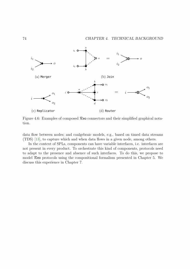
74 CHAPTER 4. TECHNICAL BACKGROUND
i1
i2
o
(a) Merger
i1
i2
a
b
o =i1
i2
o
(b) Join
o1
o2i
(c) Replicator
o1
o2
b
d
cia
=o1
o2i
(d) Router
Figure 4.6: Examples of composed Reo connectors and their simplified graphical nota-tion.
data flow between nodes; and coalgebraic models, e.g., based on timed data streams(TDS) [13], to capture which and when data flows in a given node, among others.
In the context of SPLs, components can have variable interfaces, i.e. interfaces arenot present in every product. To orchestrate this kind of components, protocols needto adapt to the presence and absence of such interfaces. To do this, we propose tomodel Reo protocols using the compositional formalism presented in Chapter 5. Wediscuss this experience in Chapter 7.
Chapter 5
Compositional Modelling ofSoftware Product Lines
This chapter discusses the compositional modelling of families of systems, in particularfamilies of real time systems through formalisms based on automata theory. In Sec-tion 4.2 we discussed an existing fine-grain formalism called featured timed automataused to represent families of real timed systems in a single model. In this chapterwe take a step forward and propose Interface Featured Timed Automata (IFTA), acompositional formalism based on both FTA and on notions of interface and I/O auto-mata [50,52]. This formalism enriches FTA with:
– variable interfaces by means of associated feature expressions that restrict theway multiple automata interact,
– multi-action labels associated to transitions that simplify the design of synchron-ous coordination, and
– a compositional semantics that takes into account the variability of the composedmodels.
The compositional semantics is the main contribution of this formalism. In ad-dition to enable verifying behavioural properties of the entire family, as one can alsodo in FTA, it allows us to reason about variability when composing models that havetheir own feature model. For example, we can verify if the composed model realizesall feature dependencies specified by an expected feature model, or if it does not intro-duce new dependencies not specified by the expected feature model. In other words, itaddress questions like: does the composed model derives the expected set of productand only those?. Furthermore, we can study how components interact at an architec-
75
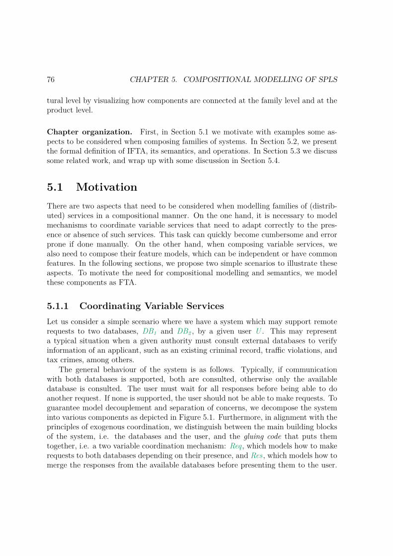
76 CHAPTER 5. COMPOSITIONAL MODELLING OF SPLS
tural level by visualizing how components are connected at the family level and at theproduct level.
Chapter organization. First, in Section 5.1 we motivate with examples some as-pects to be considered when composing families of systems. In Section 5.2, we presentthe formal definition of IFTA, its semantics, and operations. In Section 5.3 we discusssome related work, and wrap up with some discussion in Section 5.4.
5.1 MotivationThere are two aspects that need to be considered when modelling families of (distrib-uted) services in a compositional manner. On the one hand, it is necessary to modelmechanisms to coordinate variable services that need to adapt correctly to the pres-ence or absence of such services. This task can quickly become cumbersome and errorprone if done manually. On the other hand, when composing variable services, wealso need to compose their feature models, which can be independent or have commonfeatures. In the following sections, we propose two simple scenarios to illustrate theseaspects. To motivate the need for compositional modelling and semantics, we modelthese components as FTA.
5.1.1 Coordinating Variable ServicesLet us consider a simple scenario where we have a system which may support remoterequests to two databases, DB1 and DB2 , by a given user U . This may representa typical situation when a given authority must consult external databases to verifyinformation of an applicant, such as an existing criminal record, traffic violations, andtax crimes, among others.
The general behaviour of the system is as follows. Typically, if communicationwith both databases is supported, both are consulted, otherwise only the availabledatabase is consulted. The user must wait for all responses before being able to doanother request. If none is supported, the user should not be able to make requests. Toguarantee model decouplement and separation of concerns, we decompose the systeminto various components as depicted in Figure 5.1. Furthermore, in alignment with theprinciples of exogenous coordination, we distinguish between the main building blocksof the system, i.e. the databases and the user, and the gluing code that puts themtogether, i.e. a two variable coordination mechanism: Req , which models how to makerequests to both databases depending on their presence, and Res , which models how tomerge the responses from the available databases before presenting them to the user.

5.1. MOTIVATION 77
We describe each of these components below. Notice that for simplicity we avoidedintroducing time constraints in the examples. In reality each database may have itsown processing time, and the user might specify a time-out for responses.
Notation. In order to model simultaneity (synchronous steps), we adopt the notationC associated to a location as used in Uppaal. A location with C is a committed location,meaning time can not pass in that location. When an automaton in a network is in acommitted location, only outgoing transitions from there are enabled. This allows tomodel a sequence of actions executing simultaneously. For example, in the FTA Reqfrom Figure 5.1, the actions in the sequence
ℓ0request−−−−−→db1∨db2
ℓ1C
db1in−−−−−−→db1∧¬db2
ℓ0
execute simultaneously because time can not pass in location ℓ1. This notation is asimplification for the sequence
ℓ0request ,c−−−−−→db1∨db2
ℓ1c≤0
db1in−−−−−−→db1∧¬db2
ℓ0
where a clock c is reset to 0 in all incoming edges to ℓ1 and an invariant c ≤ 0 isassociated to ℓ1.
User (U ). This component has two actions, request and response, which stand forthe support to consult external databases and receive their responses, respectively. Thepresence of both actions depends on the presence of at least one database, as indicatedby the feature expression db1 ∨ db2 associated to both edges. The user can simplymake a request and wait for the response.
Databases (DB1 and DB2). Both databases have two actions, dbNin and dbNout ,which stand for the support to consult database N , for N = 1, 2, and issue the cor-responding result, respectively. Two features, db1 and db2 , represent the support fordatabase DB1 and DB2 , respectively.
Request (Req). It has three actions, request , db1in, and db2in, which synchronize1 with the equally named actions in U , DB1 and DB2 , respectively. This component
1To recall from Section 4.2.1, when automata are composed in parallel, they can synchronizedover shared action names, meaning that two automata are in a state where both can take an outgoingtransition labelled with the same action name, they transition together simultaneously, i.e., both moveto a new state. They can not transition independently over transitions with shared actions.

78 CHAPTER 5. COMPOSITIONAL MODELLING OF SPLS
coordinates how to consult the available databases if a request is issued by U . If onlyone database is present, it consults the corresponding database. For example if onlyDB1 is present, only the edge ℓ1
C
db1in−−−−−−→db1∧¬db2
ℓ0 will be present from location ℓ1. If bothare present, they are called simultaneously, i.e. db1in and db2in must be called at thesame time. This is model as a sequence of actions with committed locations. To avoidimposing an order, both possible sequence are modeled, i.e. ℓ1
db1in−−−−−→db1∧db2
ℓ2C
db2in−−−−−→db1∧db2
ℓ0
and ℓ1db2in−−−−−→
db1∧db2ℓ3C
db1in−−−−−→db1∧db2
ℓ0. If neither database is available, the entire automatonis not present, i.e., there are no transitions in the resulting projection.
Response (Res). It has three actions, response, db1out , and db2out , which synchron-ize with the same action names in U , DB1 and DB2 , respectively. This componentmerges the responses from the available databases before sending them to the user. Ifonly one database is available, it waits for the corresponding response. For example,if only DB1 is present, only the sequence ℓ0
db1out−−−−−−→db1∧¬db2
ℓ2C
response−−−−−→db1∨db2
ℓ0 will be present.If both are present, each database can have its own timing and results may be readyin any possible order. For example, the sequence ℓ0
db1out−−−−−→db1∧db2
ℓ3db2out−−−−−→db1∧db2
ℓ2 capturesdatabase DB1 returning a result before DB2 . If neither database is available, the entireautomaton is not present.
Note that both coordinators designed in Figure 5.1 correspond to two Reo connect-ors, namely, a replicator (Req) and a join (Res), here modelled with variable behaviour.
As mentioned at the beginning of Section 5.1, modelling families of services andcoordinating how they are integrated can become cumbersome and error prone. Inparticular, we recognize two potential issues, as follows.
Modeling variable coordinators. The difficulty in manually modelling such mech-anisms is twofold. First, the variability of these mechanisms depends on the variabilityof the services they orchestrate. Modelling the feature expressions associated to eachtransition is done manually taking into consideration this characteristic. This is errorprone, it can lead to erroneous behaviour such as edges that can never be taken or thatcan be taken when they should not be present; and it is inefficient when modelling com-plex coordinators. For example, in the FTA Req , if the feature expression associatedto the transition ℓ1
db1in−−−−→ ℓ0 is erroneously set to db1 ∧ db2 instead of db1 ∧ ¬db2 ,the model allows calling only database DB1 when both databases should be called.Second, the aim of these mechanisms is to coordinate how multiple actions synchronize

5.1. MOTIVATION 79
System Main Components
Databases (DB1 and DB2 ) User (U )
ℓ0 ℓ1
db1indb1
db1outdb1
ℓ0 ℓ1
db2indb2
db2outdb2
ℓ0 ℓ1
requestdb1 ∨ db2
responsedb1 ∨ db2
Coordination Components
Request (Req) Response (Res)
ℓ0
ℓ1C
ℓ2C
ℓ3C
request
db1∨db2
db1in
db1∧db2 db2in
db1∧db2
db2indb1 ∧ db2
db1indb1 ∧ db2
db2in
¬db1
∧db2
db1indb1
∧¬db2
ℓ0ℓ1
ℓ2C
ℓ3db2outdb1 ∧ db2
db1outdb1 ∧ db2
db2out
db1∧db2db
1out
db1∧db2
db2out
¬db1
∧db2 db
1out
db1∧¬d
b2response
db2∨db1
Figure 5.1: An example of a network of FTA modelling a family of systems which canmake remote requests to available databases.
and wait on each other. In many cases, this requires modelling various alternativebehaviours, i.e., alternative orders in which actions can execute. Identifying all casesmanually can be error prone and inefficient. For example, in the FTA Res , if we failto identify that DB2 may finished before DB1 , we may end up with a deadlock if thiswere to happen. Although these issues may be identified through model checking, insome cases, it depends on the formulation of the correct properties. Then, it may bedesirable to prevent this type of errors by design.
Evolving variable coordinators. Introducing changes to manually designed co-ordinators, requires to redesign the entire coordinator and calculate manually the newfeature expressions associated to transitions. This is time-consuming, and it can be-come cumbersome and error prone quickly. In our example, if in the future a thirddatabase is added, it will be necessary to redesign both coordinators entirely and cal-
80 CHAPTER 5. COMPOSITIONAL MODELLING OF SPLS
culate manually the new feature expressions. In the case of Req , such an automatonfor three databases, has 11 locations and 25 transitions.
5.1.2 Composing Variable ServicesLet us now consider a different scenario, where we have a system which may supportonline payment transactions and, if available, send email notifications if the paymentis successful. The system is divided into a payment component, P and a notificationcomponent N .
System Main Components Composed System
Payment (P) Notification (N ) (P ∥ N )
ℓ0 ℓ1
payp
confirmp
ℓ0 ℓ1
confirmn
emailnℓ0 ℓ2
ℓ1
ℓ3
payp
confirm
p∧n
emailnpayp
emailn
Figure 5.2: Example of a network of FTA modelling a family of payment systems whichmay send email confirmations
Payment (P). The service receives a payment request, pay , and emits a confirmationevent, confirm, if the payment was successful. A feature p represents the support forthe payment service, which can be present or absent, i.e., fmP = ⊤.
Notification (N ). The services receives a confirmation notification, confirm, whichsynchronizes with the same action name from P , after which it sends an email noti-fication, email . A feature n represents the support for the email notification service,which can be present or absent, i.e., fmN = ⊤.
Composed System (P ∥ N ). The composed service results from the parallel com-position of P and N , where both automata can interleave, i.e. they can jump independ-ently over non-shared actions, or synchronize over the action confirm, i.e. they jumpsimultaneously over this action. The feature expression of a synchronized transition
5.2. INTERFACE FEATURED TIMED AUTOMATA 81
is the logical conjunction of the feature expressions of independent transitions beingsynchronized.
The main issue is how the new feature model should be defined. If we simple ex-press the composed feature model as the logical conjunction of both feature models,then fmP∥N = ⊤. However, this results in a undesirable behaviour when only featurep is present. In the projected automaton (P ∥ N) ↓p, after a payment is requested,the service can no longer emit a confirmation in case of success. Thus, we need toimpose additional restrictions to the composed feature model. Intuitively, this restric-tion should impose that the synchronized actions should always be present or absenttogether. In Section 5.2.3 we present a compositional semantics that takes this intoconsideration.
5.2 Interface Featured Timed AutomataThis section introduces the proposed compositional formalism. We present IFTA syn-tax in Section 5.2.1, discuss its semantics in Section 5.2.2, and how IFTA are composedin Section 5.2.3. Finally, in Section 5.2.4 we propose a notion of IFTA equivalence bymeans of a bisimulation relation, and use it in Section 5.2.5 to study properties of IFTAcomposition.
5.2.1 SyntaxInterface Featured Timed Automata extends FTA mainly in three ways. In this sectionwe discuss the first two extensions, namely, interfaces and multi-action labels. Thecompositional semantics extension is discussed in Section 5.2.3.
First, synchronizing actions are lifted into the interface of the automaton, represent-ing the actions through which an automaton can communicate with the environment,namely, other automata when composed in parallel. A synchronizing action a, can bean input or an output action, written a? and a!, respectively. An input action representsan event expected from the environment, while an output action represents an eventsent to the environment. We say an IFTA is grounded if it has a feature expressionassociated with each interface action. This association is done only once. The featureexpression associated is inferred from the definition of the automaton. Intuitively, itrepresents the valid set of products in which an action was designed to be present.
Second, transitions can be labelled with a set of actions instead of only one actionto model simultaneous execution of actions. This simplifies significantly the designand construction of complex synchronous coordination mechanism, as we will see in

82 CHAPTER 5. COMPOSITIONAL MODELLING OF SPLS
ℓ0
request , db1in, db2in db1 ∧ db2
request , db1in db1 ∧ ¬db2
request , db2in ¬db1 ∧ db2
request?db1 ∨ db2
db1in!db1
db2in!db2
Req
fm = ⊤
Figure 5.3: A grounded IFTA corresponding to the FTA Req (Figure 5.1).
more detail in Chapter 7. A transition is enabled only when all of its actions can betaken at the same time and if the current clock valuation satisfies its clock constraint.Synchronizing actions can be taken when their dual actions on neighbour automatonare on an enabled transition. The dual of an interface action a, noted a, is defined asa! = a? and a? = a!. In addition to synchronizing actions, there are internal actions(not visible to the environment), which can always be taken if the transition is enabled.
Figure 5.3 exemplifies how the automaton Req from Figure 5.1 is modelled as anIFTA by identifying input and output actions and lifting them into the interface of theautomaton, depicted with , and by modelling simultaneous execution of actions withmulti-action labels associated to transitions.
Now we formalize the definition of IFTA, interface, feature expression of an action,and grounded IFTA.
5.2.1 Definition (Interface Featured Timed Automata). An interface featuredtimed automaton is a tuple A = (L, l0, A, C, T, Inv , F, fm, γ) where L, l0, C, Inv , F ,fm, and γ are defined as in FTA (Definition 4.2.4), and A and T are defined as follows:
– A = I ⊎O⊎H is a finite set of actions, where I is a set of input ports, O is a setof output ports, and H is a set of hidden2 (internal) actions, and
– T ⊆ L×CC(C)× 2A × 2C × L is a finite set of transitions, now labelled with aset of actions instead of a single action.
Notation. When not clear from the context, we will use LA, l0A , AA, . . . to referto the elements of an IFTA A. When using automata names with subscripts such
2Typically H = τ
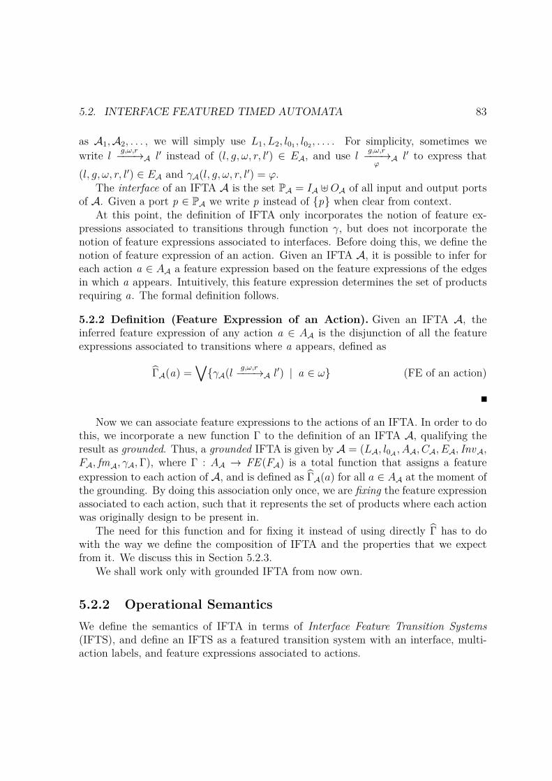
5.2. INTERFACE FEATURED TIMED AUTOMATA 83
as A1,A2, . . . , we will simply use L1, L2, l01 , l02 , . . . . For simplicity, sometimes wewrite l
g,ω,r−−−→A l′ instead of (l, g, ω, r, l′) ∈ EA, and use lg,ω,r−−−→φ
A l′ to express that(l, g, ω, r, l′) ∈ EA and γA(l, g, ω, r, l
′) = φ.The interface of an IFTA A is the set PA = IA ⊎OA of all input and output ports
of A. Given a port p ∈ PA we write p instead of p when clear from context.At this point, the definition of IFTA only incorporates the notion of feature ex-
pressions associated to transitions through function γ, but does not incorporate thenotion of feature expressions associated to interfaces. Before doing this, we define thenotion of feature expression of an action. Given an IFTA A, it is possible to infer foreach action a ∈ AA a feature expression based on the feature expressions of the edgesin which a appears. Intuitively, this feature expression determines the set of productsrequiring a. The formal definition follows.
5.2.2 Definition (Feature Expression of an Action). Given an IFTA A, theinferred feature expression of any action a ∈ AA is the disjunction of all the featureexpressions associated to transitions where a appears, defined as
ΓA(a) =∨
γA(lg,ω,r−−−→A l′) | a ∈ ω (FE of an action)
Now we can associate feature expressions to the actions of an IFTA. In order to dothis, we incorporate a new function Γ to the definition of an IFTA A, qualifying theresult as grounded. Thus, a grounded IFTA is given by A = (LA, l0A , AA, CA, EA, InvA,FA, fmA, γA,Γ), where Γ : AA → FE (FA) is a total function that assigns a featureexpression to each action of A, and is defined as ΓA(a) for all a ∈ AA at the moment ofthe grounding. By doing this association only once, we are fixing the feature expressionassociated to each action, such that it represents the set of products where each actionwas originally design to be present in.
The need for this function and for fixing it instead of using directly Γ has to dowith the way we define the composition of IFTA and the properties that we expectfrom it. We discuss this in Section 5.2.3.
We shall work only with grounded IFTA from now own.
5.2.2 Operational SemanticsWe define the semantics of IFTA in terms of Interface Feature Transition Systems(IFTS), and define an IFTS as a featured transition system with an interface, multi-action labels, and feature expressions associated to actions.
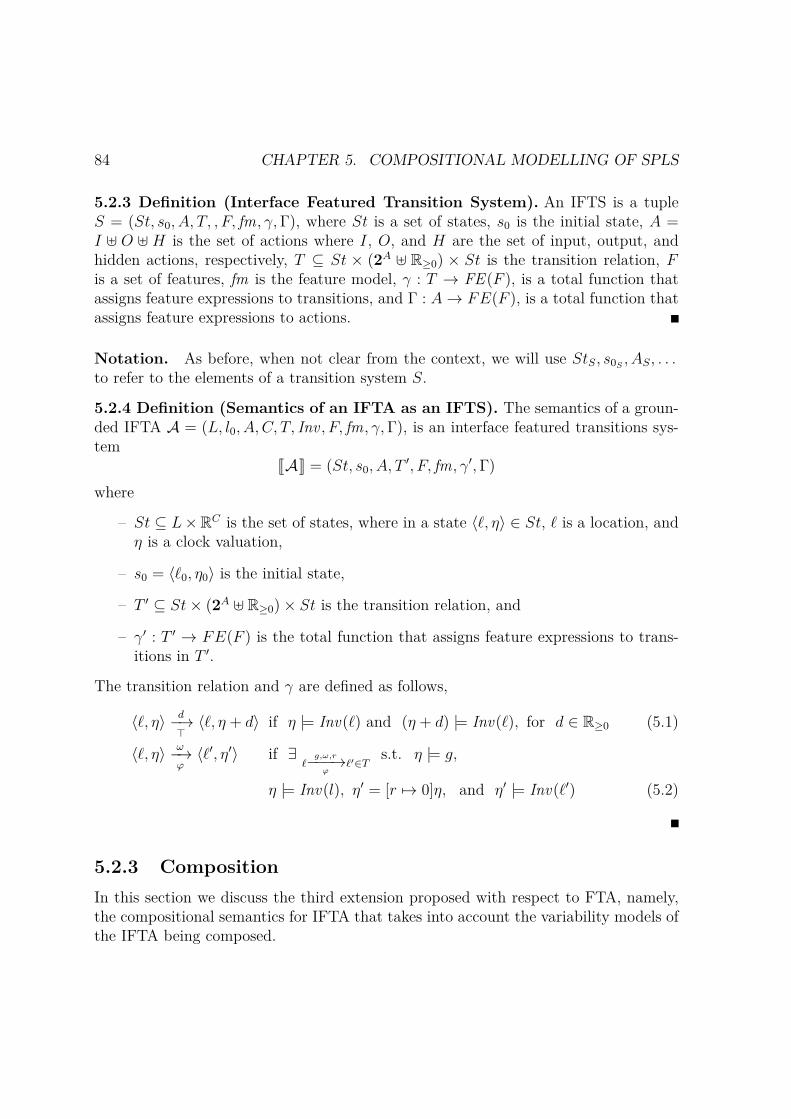
84 CHAPTER 5. COMPOSITIONAL MODELLING OF SPLS
5.2.3 Definition (Interface Featured Transition System). An IFTS is a tupleS = (St, s0, A, T, , F, fm, γ,Γ), where St is a set of states, s0 is the initial state, A =I ⊎ O ⊎ H is the set of actions where I, O, and H are the set of input, output, andhidden actions, respectively, T ⊆ St × (2A ⊎ R≥0) × St is the transition relation, Fis a set of features, fm is the feature model, γ : T → FE (F ), is a total function thatassigns feature expressions to transitions, and Γ : A → FE(F ), is a total function thatassigns feature expressions to actions.
Notation. As before, when not clear from the context, we will use StS, s0S , AS, . . .to refer to the elements of a transition system S.
5.2.4 Definition (Semantics of an IFTA as an IFTS). The semantics of a groun-ded IFTA A = (L, l0, A, C, T, Inv , F, fm, γ,Γ), is an interface featured transitions sys-tem JAK = (St, s0, A, T
′, F, fm, γ′,Γ)
where
– St ⊆ L×RC is the set of states, where in a state ⟨ℓ, η⟩ ∈ St, ℓ is a location, andη is a clock valuation,
– s0 = ⟨ℓ0, η0⟩ is the initial state,
– T ′ ⊆ St× (2A ⊎ R≥0)× St is the transition relation, and
– γ′ : T ′ → FE(F ) is the total function that assigns feature expressions to trans-itions in T ′.
The transition relation and γ are defined as follows,
⟨ℓ, η⟩ d−→⊤
⟨ℓ, η + d⟩ if η |= Inv(ℓ) and (η + d) |= Inv(ℓ), for d ∈ R≥0 (5.1)
⟨ℓ, η⟩ ω−→φ
⟨ℓ′, η′⟩ if ∃ℓ
g,ω,r−−−→φ
ℓ′∈Ts.t. η |= g,
η |= Inv(l), η′ = [r 7→ 0]η, and η′ |= Inv(ℓ′) (5.2)
5.2.3 CompositionIn this section we discuss the third extension proposed with respect to FTA, namely,the compositional semantics for IFTA that takes into account the variability models ofthe IFTA being composed.

5.2. INTERFACE FEATURED TIMED AUTOMATA 85
Informally, two IFTA can be composed by combining their feature models andlinking interfaces, imposing new restrictions over them. The composition is built ontop of two simpler operations: product and synchronization. The product operation forIFTA, unlike the classical product of timed automata, is defined over grounded IFTAwith disjoint sets of actions and clocks, performing their transitions in an interleavingor synchronous-step fashion. The formal definition of product follows.
5.2.5 Definition (Product of IFTA). Let A1 and A2, be two different groundedIFTA with disjoint actions and clocks. The product of A1 and A2, is a new IFTA
A1 ×A2 = (L1 × L2, ℓ01 × ℓ02 , A, C1 ∪ C2, F1 ∪ F2, T, Inv , fm1 ∧ fm2, γ,Γ)
where A, T , Inv , γ and Γ are defined as follows:
– A = I ⊎O ⊎H, where I = I1 ∪ I2, O = O1 ∪O2, and H = H1 ∪H2.
– T and γ are defined by the rules below, for any ω1 ⊆ A1, ω2 ⊆ A2.
ℓ1g1,ω1,r1−−−−−→
φ11 ℓ
′1
⟨ℓ1, ℓ2⟩g1,ω1,r1−−−−−→
φ1
⟨ℓ′1, ℓ2⟩
ℓ2g2,ω2,r2−−−−−→
φ22 ℓ2
′
⟨ℓ1, ℓ2⟩g2,ω2,r2−−−−−→
φ2
⟨ℓ1, ℓ′2⟩
ℓ1g1,ω1,r1−−−−−→
φ11 ℓ
′1 ℓ2
g2,ω2,r2−−−−−→φ2
2 ℓ′2
⟨ℓ1, ℓ2⟩g1∧g2,ω1∪ω2,r1∪r2−−−−−−−−−−−→
φ1∧φ2
⟨ℓ′1, ℓ′2⟩
– Inv(ℓ1, ℓ2) = Inv 1(ℓ1) ∧ Inv 2(ℓ2).
– ∀ a ∈ A · Γ(a) = Γi(a) if a ∈ Ai, for i = 1, 2.
Both top transitions represent the interleaving of both automata, i.e., either A1
takes a transition (top left) or A2 takes it (top right), but not both. The bottom trans-ition represents the synchronous execution of transitions from A1 and A2, i.e., whenboth take a transition a the same time 3. In the first two cases, the feature expressionof the existing transition in Ai, for i ∈ 1, 2, is carried to the new transition in thecomposed automata. In the last case, the feature expression of the synchronous trans-ition results from the conjunction of the feature expression associated to the transitions
3In the regular notion of product of timed automata, this is only possible over transitions with thesame shared action. However, in this case the automata do not share actions, instead we postponedthe synchronization to a later stage, by explicitly linking ports.

86 CHAPTER 5. COMPOSITIONAL MODELLING OF SPLS
being synchronised. In the case of Γ, since the intention is to maintain the original setof products for which an action a was defined to be present in, we define Γ as Γi foractions in Ai.
The synchronisation operation over an IFTA A connects and synchronises twoactions a and b in AA. The resulting automaton has transitions without neither a andb, nor both a and b.
5.2.6 Definition (Synchronisation). Given a grounded IFTA A = (L, ℓ0, A, C,F, T, Inv , fm, γ,Γ) and two actions a, b ∈ A, the synchronisation of a and b is a newIFTA
∆a,b(A) = (L, ℓ0, A′, C, F, T ′, Inv , fm ′, γ,Γ)
where A′, E ′ and fm ′ are defined as follows:
– A = I ′ ⊎O′ ⊎H ′, where I ′ = I \ a.b, O′ = O \ a.b, and H ′ = H ∪ a.b.
– T ′ = ℓ g,ω,r−−−→ ℓ′ ∈ T | a /∈ ω and b /∈ ω ∪
ℓ g,ω\a,b,r−−−−−−−→ ℓ′ | ℓ g,ω,r−−−→ ℓ′ ∈ T and a ∈ ω and b ∈ ω
– fm ′ = fm ∧ (ΓA(a) ↔ ΓA(b)).
The resulting feature model imposes new restrictions over the set of features basedon the actions being synchronised. Intuitively, if two actions a and b are synchronised,they depend on each other. Thus, we require that they should both be present or bothabsent in any valid set of features (ΓA(a) ↔ ΓA(b)).
Together, product and synchronisation can be used to obtain in a compositionalway a complex IFTA built out of more simple ones. We define the composition of twoIFTA as their product, followed by the explicit binding of actions through synchroniza-tion. The composition is defined for interface actions synchronized on an input-outputfashion only.
5.2.7 Definition (Composition of IFTA). Given two grounded IFTA, A1 andA2, with disjoint set of actions, and clocks; and a possibly empty set of bindings(a1, b1), . . . , (an, bn), such that, for each pair ai and bi, 1 ≤ i ≤ n, we have that
(ai, bi) ∈ I1 ×O2 or (ai, bi) ∈ O1 × I2 (io-only)
then their composition is a new grounded IFTA defined as follows
A1 1(a1,b1),...,(an,bn) A2 = ∆a1,b1 . . .∆an,bn(A1 ×A2)
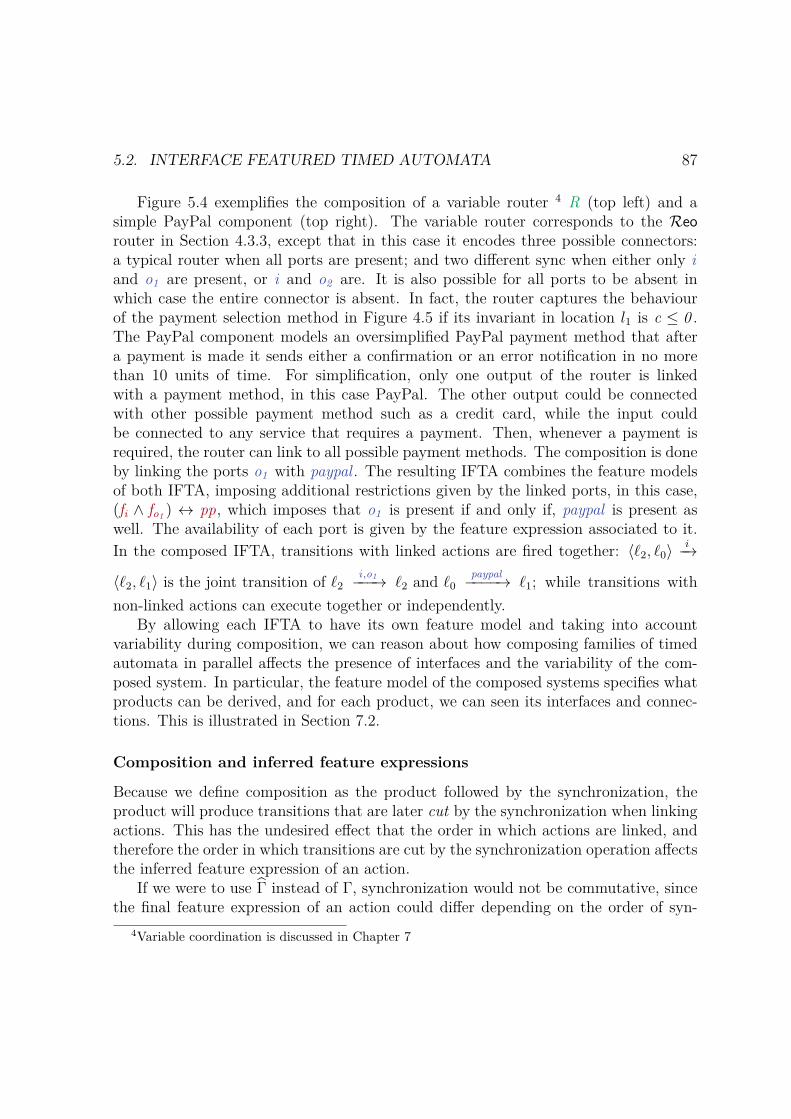
5.2. INTERFACE FEATURED TIMED AUTOMATA 87
Figure 5.4 exemplifies the composition of a variable router 4 R (top left) and asimple PayPal component (top right). The variable router corresponds to the Reorouter in Section 4.3.3, except that in this case it encodes three possible connectors:a typical router when all ports are present; and two different sync when either only iand o1 are present, or i and o2 are. It is also possible for all ports to be absent inwhich case the entire connector is absent. In fact, the router captures the behaviourof the payment selection method in Figure 4.5 if its invariant in location l1 is c ≤ 0 .The PayPal component models an oversimplified PayPal payment method that aftera payment is made it sends either a confirmation or an error notification in no morethan 10 units of time. For simplification, only one output of the router is linkedwith a payment method, in this case PayPal. The other output could be connectedwith other possible payment method such as a credit card, while the input couldbe connected to any service that requires a payment. Then, whenever a payment isrequired, the router can link to all possible payment methods. The composition is doneby linking the ports o1 with paypal . The resulting IFTA combines the feature modelsof both IFTA, imposing additional restrictions given by the linked ports, in this case,(fi ∧ fo1 ) ↔ pp, which imposes that o1 is present if and only if, paypal is present aswell. The availability of each port is given by the feature expression associated to it.In the composed IFTA, transitions with linked actions are fired together: ⟨ℓ2, ℓ0⟩
i−→
⟨ℓ2, ℓ1⟩ is the joint transition of ℓ2i ,o1−−−→ ℓ2 and ℓ0
paypal−−−−→ ℓ1; while transitions withnon-linked actions can execute together or independently.
By allowing each IFTA to have its own feature model and taking into accountvariability during composition, we can reason about how composing families of timedautomata in parallel affects the presence of interfaces and the variability of the com-posed system. In particular, the feature model of the composed systems specifies whatproducts can be derived, and for each product, we can seen its interfaces and connec-tions. This is illustrated in Section 7.2.
Composition and inferred feature expressions
Because we define composition as the product followed by the synchronization, theproduct will produce transitions that are later cut by the synchronization when linkingactions. This has the undesired effect that the order in which actions are linked, andtherefore the order in which transitions are cut by the synchronization operation affectsthe inferred feature expression of an action.
If we were to use Γ instead of Γ, synchronization would not be commutative, sincethe final feature expression of an action could differ depending on the order of syn-
4Variable coordination is discussed in Chapter 7
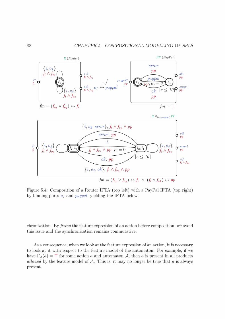
88 CHAPTER 5. COMPOSITIONAL MODELLING OF SPLS
ℓ0 ℓ1
[c ≤ 10 ]
paypalpp, c := 0
okpp
errorpp
ℓ2
i , o1fi ∧ fo1
i , o2fi ∧ fo2
i?fi
o1 !fi ∧ fo1
o2 !fi ∧ fo2
paypal?pp
ok !pp
error !pp
▷◁o1 ↔ paypal
fm = (fo1 ∨ fo2 ) ↔ fi fm = ⊤
R (Router) PP (PayPal)
l2, l0 l2, l1
[c ≤ 10 ]
i , o2 , error, fi ∧ fo2 ∧ pp
error , ppi
fi ∧ fo1 ∧ pp, c := 0
ok , pp
i , o2fi ∧ fo2
i , o2fi ∧ fo2
i , o2 , ok, fi ∧ fo2 ∧ pp
fm = (fo1 ∨ fo2 ) ↔ fi ∧ (fi ∧ fo1 ) ↔ pp
i?fi
ok !pp
error !pp
o2 !fi ∧ fo2
R 1(o1 ,paypal)PP
Figure 5.4: Composition of a Router IFTA (top left) with a PayPal IFTA (top right)by binding ports o1 and paypal , yielding the IFTA below.
chronization. By fixing the feature expression of an action before composition, we avoidthis issue and the synchronization remains commutative.
As a consequence, when we look at the feature expression of an action, it is necessaryto look at it with respect to the feature model of the automaton. For example, if wehave ΓA(a) = ⊤ for some action a and automaton A, then a is present in all productsallowed by the feature model of A. This is, it may no longer be true that a is alwayspresent.
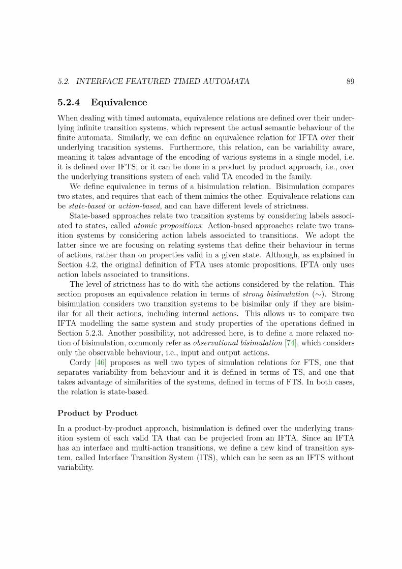
5.2. INTERFACE FEATURED TIMED AUTOMATA 89
5.2.4 EquivalenceWhen dealing with timed automata, equivalence relations are defined over their under-lying infinite transition systems, which represent the actual semantic behaviour of thefinite automata. Similarly, we can define an equivalence relation for IFTA over theirunderlying transition systems. Furthermore, this relation, can be variability aware,meaning it takes advantage of the encoding of various systems in a single model, i.e.it is defined over IFTS; or it can be done in a product by product approach, i.e., overthe underlying transitions system of each valid TA encoded in the family.
We define equivalence in terms of a bisimulation relation. Bisimulation comparestwo states, and requires that each of them mimics the other. Equivalence relations canbe state-based or action-based, and can have different levels of strictness.
State-based approaches relate two transition systems by considering labels associ-ated to states, called atomic propositions. Action-based approaches relate two trans-ition systems by considering action labels associated to transitions. We adopt thelatter since we are focusing on relating systems that define their behaviour in termsof actions, rather than on properties valid in a given state. Although, as explained inSection 4.2, the original definition of FTA uses atomic propositions, IFTA only usesaction labels associated to transitions.
The level of strictness has to do with the actions considered by the relation. Thissection proposes an equivalence relation in terms of strong bisimulation (∼). Strongbisimulation considers two transition systems to be bisimilar only if they are bisim-ilar for all their actions, including internal actions. This allows us to compare twoIFTA modelling the same system and study properties of the operations defined inSection 5.2.3. Another possibility, not addressed here, is to define a more relaxed no-tion of bisimulation, commonly refer as observational bisimulation [74], which considersonly the observable behaviour, i.e., input and output actions.
Cordy [46] proposes as well two types of simulation relations for FTS, one thatseparates variability from behaviour and it is defined in terms of TS, and one thattakes advantage of similarities of the systems, defined in terms of FTS. In both cases,the relation is state-based.
Product by Product
In a product-by-product approach, bisimulation is defined over the underlying trans-ition system of each valid TA that can be projected from an IFTA. Since an IFTAhas an interface and multi-action transitions, we define a new kind of transition sys-tem, called Interface Transition System (ITS), which can be seen as an IFTS withoutvariability.
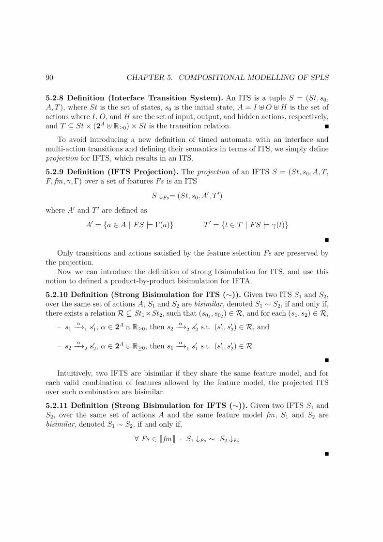
90 CHAPTER 5. COMPOSITIONAL MODELLING OF SPLS
5.2.8 Definition (Interface Transition System). An ITS is a tuple S = (St, s0,A, T ), where St is the set of states, s0 is the initial state, A = I ⊎ O ⊎H is the set ofactions where I, O, and H are the set of input, output, and hidden actions, respectively,and T ⊆ St× (2A ⊎ R≥0)× St is the transition relation.
To avoid introducing a new definition of timed automata with an interface andmulti-action transitions and defining their semantics in terms of ITS, we simply defineprojection for IFTS, which results in an ITS.
5.2.9 Definition (IFTS Projection). The projection of an IFTS S = (St, s0, A, T,F, fm, γ,Γ) over a set of features Fs is an ITS
S ↓Fs= (St, s0, A′, T ′)
where A′ and T ′ are defined as
A′ = a ∈ A | FS |= Γ(a) T ′ = t ∈ T | FS |= γ(t)
Only transitions and actions satisfied by the feature selection Fs are preserved bythe projection.
Now we can introduce the definition of strong bisimulation for ITS, and use thisnotion to defined a product-by-product bisimulation for IFTA.
5.2.10 Definition (Strong Bisimulation for ITS (∼)). Given two ITS S1 and S2,over the same set of actions A, S1 and S2 are bisimilar, denoted S1 ∼ S2, if and only if,there exists a relation R ⊆ St1×St2, such that (s01 , s02) ∈ R, and for each (s1, s2) ∈ R,
– s1α−→1 s
′1, α ∈ 2A ⊎ R≥0, then s2
α−→2 s′2 s.t. (s′1, s
′2) ∈ R, and
– s2α−→2 s
′2, α ∈ 2A ⊎ R≥0, then s1
α−→1 s′1 s.t. (s′1, s
′2) ∈ R
Intuitively, two IFTS are bisimilar if they share the same feature model, and foreach valid combination of features allowed by the feature model, the projected ITSover such combination are bisimilar.
5.2.11 Definition (Strong Bisimulation for IFTS (∼)). Given two IFTS S1 andS2, over the same set of actions A and the same feature model fm, S1 and S2 arebisimilar, denoted S1 ∼ S2, if and only if,
∀ Fs ∈ Jfm K · S1 ↓Fs ∼ S2 ↓Fs

5.2. INTERFACE FEATURED TIMED AUTOMATA 91
We say two IFTA A1 and A2 are bisimilar, A1 ∼ A2, if and only if, their underlyingtransition systems are bisimilar, i.e., if and only if, JA1K ∼ JA2K.
The following figure illustrates the relation between the various formalisms definedhere. Gray lines correspond to definitions that have been left out for simplification.
IFTA ITA
IFTS ITS
↓Fs
J K↓Fs
J K
The semantic of an IFTA results in an IFTS (Definition 5.2.3), while the projection ofan IFTS over a feature selection Fs results in an ITS. If we were to define a kind ofInterface TA with multi-action transitions, we could project IFTA into the same Fsand obtained an ITA, whose semantics will be an ITS, bisimilar to the one obtainedthrought the previous step.
Variability-aware
Now we can introduce a variability aware bisimulation relation that takes advantageof the compact structure of IFTS.
5.2.12 Definition (Strong Bisimulation for IFTS (∼)). Given two IFTS S1 andS2, over the same set of actions A and the same feature model fm, S1 and S2 arebisimilar, denoted S1 ∼ S2, if and only if, there exists R ⊆ St1 × St2, such that(s01 , s02) ∈ R, and for each (s1, s2) ∈ R,
– s1α−−→φ1
1 s′1, α ∈ 2A ⊎ R≥0, then s2α−−→φ2
2 s′2 s.t. |= fm → (φ1 → φ2) and(s′1, s
′2) ∈ R, and
– s2α−−→φ2
2 s′2, α ∈ 2A ⊎ R≥0, then s1α−−→φ1
1 s′1 s.t. |= fm → (φ2 → φ1) and(s′1, s
′2) ∈ R
The feature expression fm → (φ1 → φ2) requires that φ2 should be satisfied in allvalid products of the feature model in which φ1 is satisfied, i.e. whenever s1
α−→ s′1 is
present in a product, so is s2α−→ s′2.

92 CHAPTER 5. COMPOSITIONAL MODELLING OF SPLS
A disadvantage of this definition is that it only recognizes two IFTS as bisimilarif they are bisimilar for all the valid set of products specified by their feature model.However, when comparing two systems, it might be of interest to know as well the setof products for which they are bisimilar. We follow Cordy approach [46], and modelbisimulation as a function that captures the set of products for which S1 and S2 arebisimilar.
5.2.13 Definition (Featured-bisimulation). Given two IFTS S1 and S2, over thesame sets of actions A, features F , and feature model fm ∈ FE (F ), a featured-bisimulation for S1 and S2 is a binary function R : St1 × St2 → FE (F ) such that
R(s1, s2) =∧
s1ω−−→φ1
1s′1
(φ1 ⇒∨
s2ω−−→φ2
2s′2
(φ2 ∧R(s′1, s′2))) ∧
∧∧
s2ω−−→φ2
2s′2
(φ2 ⇒∨
s1ω−−→φ1
1s′1
(φ1 ∧R(s′1, s′2)))
Then, let Fs ∈ Jfm KF be a valid product of both IFTS, S1 and S2 are bisimilar forFs if and only if Fs |= R(s01 , s02). Furthermore, let Rmax be the largest bisimulationfor S1 and S2, then Rmax (s01 , s02) encodes the set of products for which S1 and S2
are bisimilar, where by largest it refers to the fact that given any other bisimulationR(s01 , s02), we have that R(s01 , s02) ⇒ Rmax (s01 , s02). It should be notice that thisset of products must be considered in the context of the feature model, this is, it ispossible that some feature configuration for which the automata are bisimilar is notallowed by the feature model.
5.2.1 Theorem. Let S1 and S2 be two IFTS over the same set of actions A, featuresF , and feature model fm ∈ FE (F ). Given a valid feature selection Fs ∈ Jfm KF ,Fs |= R(s01 , s02) ⇔ S1 ↓Fs∼ S2 ↓Fs
Proof. Let us first consider (⇒). If Fs |= R(s01 , s02) we have that for all
s01ω−−→φ1
1 s′1 s.t. Fs |= φ1 there exists some s02
ω−−→φ2
2 s′2 s.t. Fs |= φ2 ∧R(s′1, s
′2)
and for all
s02ω−−→φ2
2 s′2 s.t. Fs |= φ2 there exists some s01
ω−−→φ1
1 s′1 s.t. Fs |= φ1 ∧R(s′1, s
′2)

5.2. INTERFACE FEATURED TIMED AUTOMATA 93
In other words, for all transitions s01ω−−→φ1
1 s′1 that exist in a product given by Fs ,
i.e. exist in S1 ↓Fs , there is at least a transition s02ω−−→φ2
2 s′2 that exist in S2 ↓Fsand such that the same is valid for transitions starting from (s′1, s
′2); and such that
for all s02ω−−→φ2
2 s′2 that exist in a product given by Fs , i.e. exist in S2 ↓Fs , there is
at least a transition s01ω−−→φ1
1 s′1 that exist in S1 ↓Fs and such that the same is validfor transitions starting from (s′1, s
′2). This corresponds exactly with both conditions in
Definition 5.2.10. Then, S1 ↓Fs∼ S2 ↓Fs.Let us now consider (⇐). If S1 ↓Fs∼ S2 ↓Fs, then let RFs be the bisimulation
relation for S1 ↓Fs∼ S2 ↓Fs such that (s01 , s02) ∈ RFs . By Definition 5.2.10, for all(s1, s2) ∈ RFs , including (s01 , s02), we have that for all
s1ω−→S1↓Fs
s′1 there exists some s2ω−→S2↓Fs
s′2 s.t. (s′1, s′2) ∈ RFs
and for all
s2ω−→S2↓Fs
s′2 there exists some s1ω−→S1↓Fs
s′1 s.t. (s′1, s′2) ∈ RFs
and since these are projections over Fs , we have that
if Fs |= γS1(s1ω−→S1
s′1) then Fs |= γS2(s2ω−→S2
s′2), and
if Fs |= γS2(s2ω−→S2
s′2) then Fs |= γS1(s1ω−→S1
s′1)
The same is valid for transitions starting from (s′1, s′2). Then, Fs |= R(s01 , s02).
5.2.5 PropertiesOperations over IFTA satisfy the usual properties up to strong bisimulation (∼).
5.2.2 Theorem. Given two IFTA A1 and A2 with disjoint sets of actions and clocks,we have:
A1 ×A2 ∼ A2 ×A1 (×-commutativity)A1 × (A2 ×A3) ∼ (A1 ×A2)×A3 (×-associativity)
Proof. Both proofs follow trivially from the definition of product and of the underly-ing IFTS of each IFTA, and because ∪ and ∧ are associative and commutative. Inparticular, commutativity follows from the fact that
R = (⟨(l1, l2), η⟩, ⟨(l2, l1), η⟩) | ⟨(l1, l2), η⟩ ∈ St JA1 K
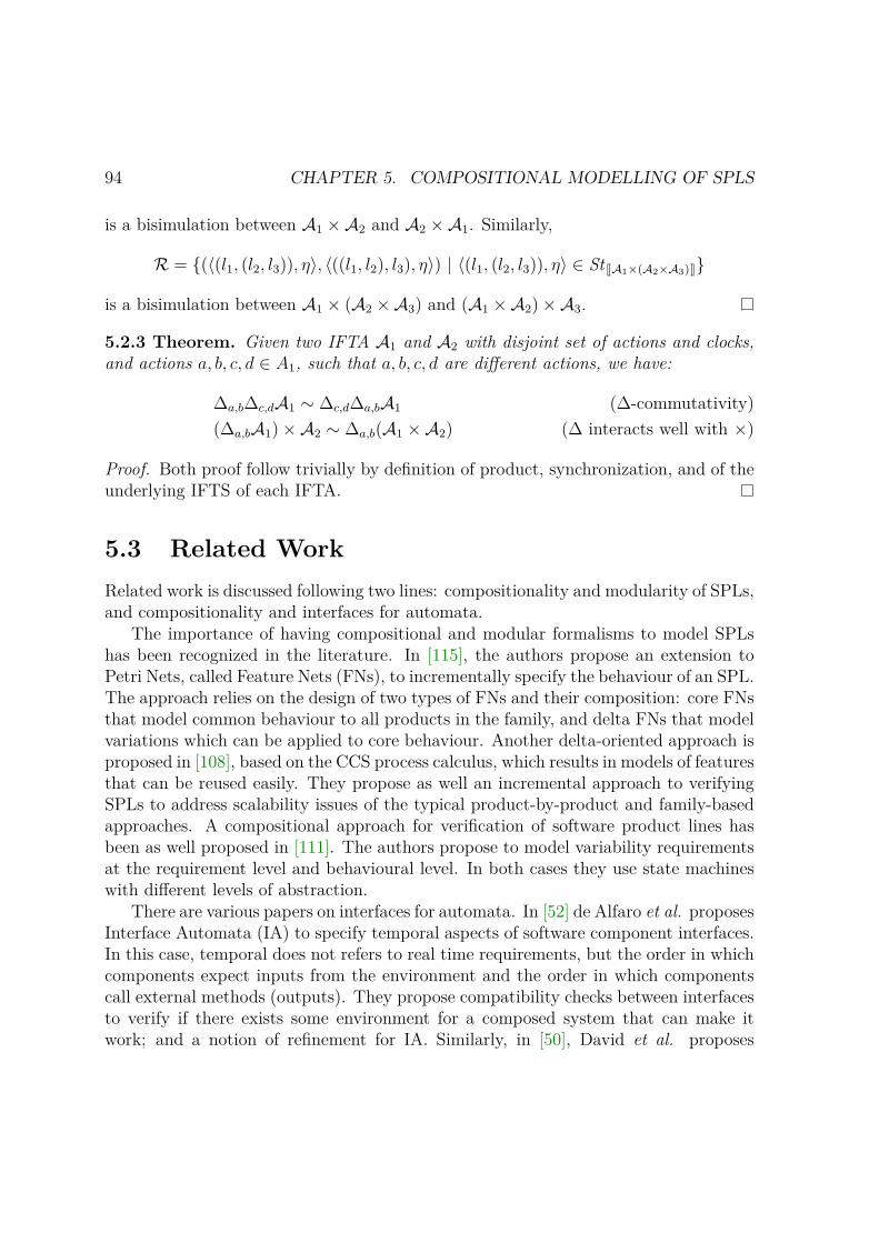
94 CHAPTER 5. COMPOSITIONAL MODELLING OF SPLS
is a bisimulation between A1 ×A2 and A2 ×A1. Similarly,
R = (⟨(l1, (l2, l3)), η⟩, ⟨((l1, l2), l3), η⟩) | ⟨(l1, (l2, l3)), η⟩ ∈ St JA1×(A2×A3)Kis a bisimulation between A1 × (A2 ×A3) and (A1 ×A2)×A3.
5.2.3 Theorem. Given two IFTA A1 and A2 with disjoint set of actions and clocks,and actions a, b, c, d ∈ A1, such that a, b, c, d are different actions, we have:
∆a,b∆c,dA1 ∼ ∆c,d∆a,bA1 (∆-commutativity)(∆a,bA1)×A2 ∼ ∆a,b(A1 ×A2) (∆ interacts well with ×)
Proof. Both proof follow trivially by definition of product, synchronization, and of theunderlying IFTS of each IFTA.
5.3 Related WorkRelated work is discussed following two lines: compositionality and modularity of SPLs,and compositionality and interfaces for automata.
The importance of having compositional and modular formalisms to model SPLshas been recognized in the literature. In [115], the authors propose an extension toPetri Nets, called Feature Nets (FNs), to incrementally specify the behaviour of an SPL.The approach relies on the design of two types of FNs and their composition: core FNsthat model common behaviour to all products in the family, and delta FNs that modelvariations which can be applied to core behaviour. Another delta-oriented approach isproposed in [108], based on the CCS process calculus, which results in models of featuresthat can be reused easily. They propose as well an incremental approach to verifyingSPLs to address scalability issues of the typical product-by-product and family-basedapproaches. A compositional approach for verification of software product lines hasbeen as well proposed in [111]. The authors propose to model variability requirementsat the requirement level and behavioural level. In both cases they use state machineswith different levels of abstraction.
There are various papers on interfaces for automata. In [52] de Alfaro et al. proposesInterface Automata (IA) to specify temporal aspects of software component interfaces.In this case, temporal does not refers to real time requirements, but the order in whichcomponents expect inputs from the environment and the order in which componentscall external methods (outputs). They propose compatibility checks between interfacesto verify if there exists some environment for a composed system that can make itwork; and a notion of refinement for IA. Similarly, in [50], David et al. proposes

5.4. DISCUSSION 95
a specification theory for Timed I/O Automata (TIOA), and defines correspondingnotions of composition and refinement for (TIOA), among other operations. However,their theory is based on input enabled automata. In Chapter 6, we propose a notion ofrefinement for IFTA that takes concepts from both theories. Finally, in [103], ModalI/O automata are proposed as an extension to IA and used to construct a behaviouralvariability theory for SPL development that can serve to verify if certain requirementscan be satisfied from a set of existing assets. However, variability is achieved only bymeans of must (present in all products) or may (optionally present) transitions.
5.4 DiscussionInterface featured timed automata combines notions from FTA, the theory of automatawith interfaces, and component-based design. The result is a formalism capable ofmodelling SPLs in an incremental and modular way.
In this sense, the main contribution of IFTA is the definition of its compositionoperation. In addition to making possible incremental design, it allows to verify prop-erties of the composed model against an expected feature model, i.e. to discuss whetherthe composed model is able to derive the expected products and only those. It is worthmentioning that the approach used to compose feature models is not unique, and thereare other approaches that could be explored [1].
The proposed definition has, however, some disadvantages.First, by forming the product and later applying synchronization, the product auto-
mata will possess unnecessary transitions and states that later will be cut, in the caseof transitions, or become unreachable, in the case of states. This is inefficient whencalculating the composed automata. In practice, it will be better to rename with thesame action name interfaces that will be synchronized before computing the product,and define the product to synchronize only transitions with the same shared actionsand to interleave only on transitions with non-shared actions. This way, we avoid cre-ating transitions that will later be cut and we remove unreachable states at an earlystage. In [37] we document a proof-of-concept prototype to specify, compose, visualize,and translate IFTA models into other formalisms. In this tool we implement both ap-proaches to IFTA composition: synchronization on shared action names, and productfollowed by synchronization. Section 8.4.2 briefly introduces this prototype.
Second, as discussed in Section 5.2.3, we fix the feature expression of an action be-fore the product in order to achieve commutativity in the composition. This obfuscatethe interpretation of feature expression of an action.
In order to simplify the design of synchronous coordination mechanisms, we mod-elled simultaneous execution of actions as multi-actions associated to transitions. This

96 CHAPTER 5. COMPOSITIONAL MODELLING OF SPLS
is also the approach used by constraint automata [17], one of the commonly used form-alism to express the semantics of Reo. In practice, there are other ways of achievingthis. For example, Uppaal provides committed locations, and non-blocking broadcast.In the latter, an output can synchronized with various inputs in a non-blocking way,i.e., it will synchronize only with the inputs that are enabled at the moment. Non-blocking broadcasting can be achieved through the use of variables and other controlmechanism. The disadvantage of these approaches based on committed locations andbroadcasting, is to increase complexity in the modelling stage.

Chapter 6
Refinement of Interface FeaturedTimed Automata
6.1 IntroductionAs it happens in the development of any complex system, common and variable assetsof an SPL, such as software components, can be designed and developed by differentengineers agreeing on a common specification of what their interfaces should be. Inthis sense, being able to reason about how standalone components, and in this casefamilies of components, implemented separately satisfy a given specification becomescrucial. In this chapter, we propose a notion of refinement for real timed softwareproduct lines that are modelled as Interface Featured Timed Automata.
Refinement allows us to compare two models of the same system presented atdifferent levels of abstraction. The most abstract one is referred to as the specification,while the most detailed one is referred to as an implementation of the system. Ifan implementation refines the specification, it agrees with the requirements of thespecification in the sense that one may replace the implementation in any contextwhere the specification is used, and still obtain a congruent system. However, sincewe are dealing with families of components, we need to reason about how a set ofimplementations refine a set of specifications.
Figure 6.1 illustrates this problem. The figure shows two composed systems (top):one (top left), composed by an IFTA C, representing a context (here left undefined),and an IFTA P corresponding to the payment selection mechanism in Figure 4.5. Theother (top right), which is a refinement of the system on the left, is composed bythe same context C , and a new selection mechanism P ′ (defined in Figure 6.3). Thegoal is to define a refinement relation that is compositional, i.e. such that it shouldbe sufficient to verify if P ′ refines P instead of verifying if the composed system on
97

98 CHAPTER 6. REFINEMENT OF IFTA
P3P2P1
P(Figure 6.2)
C(Context)
pay?pp ∨ ccpaypal !
ppcard !
cc
fm = pp ∨ cc
(models)fm = φ
⪰(refined by)
P’4P’3P’2P’1
P’(Figure 6.2)
C(Context)
pay?pp ∨ cc ∨ bk
paypal !pp
card !cc
cancel?c
fm = pp ∨ ccfm = φ
(models)
Figure 6.1: Example scenario when reasoning about refinement of families of compon-ents. A system composed by two IFTA, C and P (left), is refined by a more detailedsystem composed by the same IFTA C and a new IFTA P’ (right).
the right refines the composed system on the left. However, we need to consider inaddition that both automata, P and P ′, are actually families of components whichmodel different concrete automata, as depicted in Figure 6.1 (bottom). Thus, we needto reason about how each of the new automata P ′
i , for i = 1, . . . , 4, refines the automataPj , for j = 1, 2. Informally, the notion of refinement proposed requires that each newautomaton of P ′ refines an automata of P , and that all automata of P are refined by,at least, an automaton of P ′. To simplify reasoning, we first define refinement overITS and then re-build our definition of IFTA refinement over this simpler one.
We show that refinement is a pre-order and congruent with respect to IFTA opera-tions, meaning refinement is compositional. However, as it is discussed in Section 6.2,stronger pre-conditions must be assumed on the variability model of both automatafor the congruent result to hold.
In addition, we propose a variability-aware refinement defined directly over IFTS,which takes into account the variability encoded in the model, capturing the set ofproducts for which an IFTS refines another.
Chapter Organization. In Section 6.2 we discuss the product by product refinementrelation and its properties. We present the variability-aware refinement in Section 6.3and conclude by discussing the advantages and limitations of the refinement relationin Section 6.4.
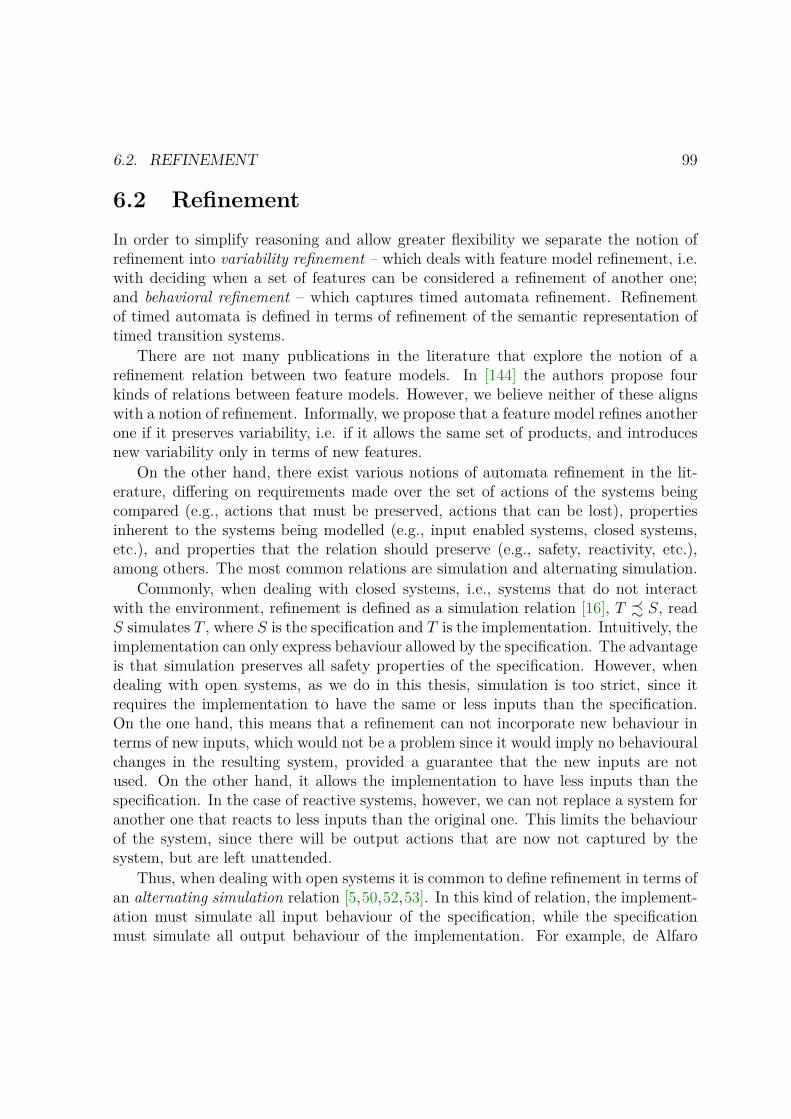
6.2. REFINEMENT 99
6.2 RefinementIn order to simplify reasoning and allow greater flexibility we separate the notion ofrefinement into variability refinement – which deals with feature model refinement, i.e.with deciding when a set of features can be considered a refinement of another one;and behavioral refinement – which captures timed automata refinement. Refinementof timed automata is defined in terms of refinement of the semantic representation oftimed transition systems.
There are not many publications in the literature that explore the notion of arefinement relation between two feature models. In [144] the authors propose fourkinds of relations between feature models. However, we believe neither of these alignswith a notion of refinement. Informally, we propose that a feature model refines anotherone if it preserves variability, i.e. if it allows the same set of products, and introducesnew variability only in terms of new features.
On the other hand, there exist various notions of automata refinement in the lit-erature, differing on requirements made over the set of actions of the systems beingcompared (e.g., actions that must be preserved, actions that can be lost), propertiesinherent to the systems being modelled (e.g., input enabled systems, closed systems,etc.), and properties that the relation should preserve (e.g., safety, reactivity, etc.),among others. The most common relations are simulation and alternating simulation.
Commonly, when dealing with closed systems, i.e., systems that do not interactwith the environment, refinement is defined as a simulation relation [16], T ≾ S, readS simulates T , where S is the specification and T is the implementation. Intuitively, theimplementation can only express behaviour allowed by the specification. The advantageis that simulation preserves all safety properties of the specification. However, whendealing with open systems, as we do in this thesis, simulation is too strict, since itrequires the implementation to have the same or less inputs than the specification.On the one hand, this means that a refinement can not incorporate new behaviour interms of new inputs, which would not be a problem since it would imply no behaviouralchanges in the resulting system, provided a guarantee that the new inputs are notused. On the other hand, it allows the implementation to have less inputs than thespecification. In the case of reactive systems, however, we can not replace a system foranother one that reacts to less inputs than the original one. This limits the behaviourof the system, since there will be output actions that are now not captured by thesystem, but are left unattended.
Thus, when dealing with open systems it is common to define refinement in terms ofan alternating simulation relation [5,50,52,53]. In this kind of relation, the implement-ation must simulate all input behaviour of the specification, while the specificationmust simulate all output behaviour of the implementation. For example, de Alfaro

100 CHAPTER 6. REFINEMENT OF IFTA
et. al. [53] introduces Interface Automata, without time, and define the notion of re-finement in terms of alternating simulation, extended to support internal steps, i.e.,internal actions from both automata which are independent from each other. In [50]David et. al. provided a complete specification theory for Timed I/O Automata wherethey defined refinement, logical conjunction, structural composition, and a quotientoperator. However, their theory is based on input enabled automata.
The rest of this section is divided as follows. We first discuss variability and beha-vioural refinement and in Section 6.2.1 and Section 6.2.2, respectively. Then we buildthe definition of IFTA refinement on top of these simpler concepts. Finally, we discussproperties of the refinement relation, and conclude by discussing some advantages anddisadvantages of the relation proposed.
6.2.1 Variability Refinement
Thum et al. [144] proposed an algorithm to reason about the relation between twofeature models, fm1 and fm2, independently of whether they share the exact same setof features, or not. They recognize four type of relations: refactoring or equivalence –fm1 and fm2 express the same set of products; specialization – fm1 specializes fm2 if theset of products of fm1 is a subset of the set of products expressed by fm2; generalization– fm1 generalizes fm2 if and only if the set of products of fm1 is a superset of the setof products of fm2; and arbitrary – otherwise.
However, in order to reason about refinement of families of timed automata wealso would like to relate feature models in terms of a refinement relation. There aredifferent ways in which variability refinement can be defined, here we propose onethat suits better in order to guarantee congruency with IFTA operations. However,in Section 6.4 we discuss some alternatives that can be considered and briefly hint onwhat are the main implications of these choices.
Intuitively, a feature model fm1 refines a feature model fm2 if when considering theset of features of fm2, fm1 expresses exactly the same set of products expressed by fm2.Thus, fm1 can add new variability or details only in terms of new features, but mustpreserve the set of features in fm2. Formally, if we consider feature models with onlyterminal features [144], i.e., no abstract features, we define feature model refinementas follows.
6.2.1 Definition (Feature model refinement). Given two feature models fm i ∈FE(Fi) over a set of features Fi, i = 1, 2, fm1 refines fm2, denoted fm1 ⊑ fm2, if and

6.2. REFINEMENT 101
only if,
F1 ⊇ F2 (preserves features)Jfm1KF1|F2= Jfm2KF2 (preserves products)
where Jfm KF |F ′ = FS ∩ F ′ | FS ∈ Jfm KF.
For example, if consider the payment selection methods P and P ′ from Figure 6.2,we have that JfmP K = pp, cc, pp, cc and JfmP ′ K = pp, cc, c, pp, cc,pp, c, cc, c, pp, cc. When we restrict fmP ′ to consider only features in FP ,we have that JfmP ′ K|FP
= pp, cc,c, pp, cc, pp,c, cc,c, pp, cc = JfmP K,wherec means that feature c is removed from the set. Thus, fmP ′ ⊑ fmP .
However, let us assume that the feature model of P ′ is now fmP ′ = pp ∨ cc ∨c. Then, we have that JfmP ′ K|FP
= pp, cc,c, pp, cc, pp,c, cc,c, pp, cc,c = JfmP K. Because now P ′ allows a product that does not support neither PayPalnor credit card payments, P ′ no longer refines P .
6.2.1 Theorem (⊑ is a partial order). For any feature model fm i, for i = 1, 2, 3,fm1 ⊑ fm1; if fm1 ⊑ fm2 and fm2 ⊑ fm3, then fm1 ⊑ fm3; and if fm1 ⊑ fm2 andfm2 ⊑ fm1, then fm1 ≡ fm2.
Proof. The reflexive and antisymmetric properties are trivial by definition of set inclu-sion and set intersection.
In the case of transitivity, first note that by transitivity of set inclusion we havethat F1 ⊇ F3. Then,∪
Fs∈Jfm1 KF1
Fs ∩ F2 = Jfm2KF2 by fm1 ⊑ fm2 (6.1)
∪Fs∈Jfm2 KF2
Fs ∩ F3 = Jfm3KF3 by fm2 ⊑ fm3 (6.2)
∪Fs∈Jfm1 KF1
Fs ∩ F2 ∩ F3 = Jfm3KF3 by (6.1) and (6.2) (6.3)
∪Fs∈Jfm1 KF1
Fs ∩ F3 = Jfm3KF3 by (6.3) and F2 ⊇ F3 (6.4)
where∪
Fs∈Jfm1 KF1 (Fs ∩ F3) is exactly the definition of Jfm1KF1|F3.
Thus, fm1 ⊑ fm3, and ⊑ is a partial order.

102 CHAPTER 6. REFINEMENT OF IFTA
6.2.2 Behavioural RefinementRefinement allows to verify if a given implementation agrees with a specification. Weconsider implementations as automata that are more detailed specifications. Intuit-ively, an automata A that refines an automata B should be able to replace B in everycontext in which B appears. Our notion of refinement is similar to the one in [52],where there is an alternating simulation between both automata: A must simulate allinput behavior of B, while B must simulate all output behavior from A. Thus, A canallow more legal inputs, and fewer outputs, than B.
Similarly to [50] we define refinement at the semantic level, i.e., at the level oftransition systems and then build up towards IFTA refinement. Because we separaterefinement into variability and behavioural refinement, our base notion of refinementis defined for Interface Transition Systems (Definition 5.2.8), i.e., IFTS without vari-ability.
In fact, our notion of refinement can be seen as an extension of [52] for timed systemswith multi-action transitions. Here as well, the definition of refinement must considerthe fact that both automata have internal actions which are independent from eachother. Additionally, since we are dealing with timed transition systems, the definitionof refinement must consider that internal steps can incorporate delays. Thus, we definea transition relation that captures all transition steps possible from a state s to a states′ by any combination of internal and delay steps.
6.2.2 Definition. Given an ITS S and states s, s′ ∈ StS, notation sτ∗==⇒d
S s′ meansthat there is a sequence of transition steps from TS, such that
sωi−−→
Ss1 . . . sn
ωn−−→Ss′
with ωi ∈ τ ⊎ R≥0 and such that (∑
ωi∈R≥0ωi) = d. For simplicity, we use s
ω=⇒d
S s′ ifthere is a sequence of transition steps from TS, such that
sτ∗==⇒d
S snω−→
Ss′
with ω ∈ 2A.
In this context, ITS refinement is defined as follows.
6.2.3 Definition (Refinement of ITS). Given two ITS, S and T , such that IT ⊆ ISand OS ⊆ OT , S refines T , denoted S ⪯ T , if and only if, there exists a relationR ⊆ StS × StT , such that (s0, t0) ∈ R and for each (s, t) ∈ R,
6.2. REFINEMENT 103
1. sτ∗==⇒d
S s′, d ∈ R≥0 then tτ∗==⇒d
T t′ and (s′, t′) ∈ R, for some t′ ∈ StT
2. sOIs==⇒d
S s′, d ∈ R≥0, O = ∅ then tOIs==⇒d
T t′ and (s′, t′) ∈ R for some t′ ∈ StT
3. tIO==⇒d
T t′, d ∈ R≥0, I = ∅ then sIO==⇒d
S s′ and (s′, t′) ∈ R for some s′ ∈ StS
where Is is either ∅, or has only inputs shared by both automata, Is ⊆ IT .
Condition 1 expresses that any delay allowed from s, must be a delay allowed from t,possible by taken some internal steps. Condition 2 expresses that any output transition,which may have inputs that are shared by both systems, and that can be taken from safter a delay d, possible by taking some internal steps, must simulate a (sequence of)transition(s) from t. Notice that if there is a multi-action transition with outputs andinputs, such that the inputs include inputs available only in the implementation, thisis considered as new behaviour incorporated by the use of new inputs, and as such,it is ignored. Condition 3 expresses that any input transition, with possible outputs,taken from t after a delay d, possibly with some internal steps, must be simulated bya (sequence of) transition(s) from s.
In comparison with de Alfaro et. al., we relax some of the requirements made overthe states being compared, s and t. In particular, when considering input labeledtransitions (condition 3), de Alfaro et. al. defines that s and t are in a refinementrelation, only if, whenever in t is possible to receive an input, s may receive the sameinput. Here, we require that whenever in t is possible to receive an input within acertain time, possibly trough a sequence of internal steps, s may receive the sameinput within the same time, possibly through a series of internal steps. In other words,de Alfaro requires T and S to be immediately ready to receive the input in state tand s, respectively, while we required that S must receive the input within the sameamount of time that T from t, but may still perform internal actions from s beforethat.
6.2.3 IFTA RefinementBefore formalizing refinement for families of timed automata, let us consider refinementfor IFTS. Informally, given two IFTS, S and T , S refines T if for each valid product inS, the projection of S onto such a product refines the projection of T onto the sameproduct. However, depending on the relation existing between the set of products of Sand T , this can lead to different notions of refinement. As presented in Section 6.2.1,we propose that S should preserve the variability of T , i.e. S should allow exactlythe same products as T , although it may also increase the set of features and allow
104 CHAPTER 6. REFINEMENT OF IFTA
more products with respect to the new features. We will discuss other possibilities inSection 6.4. Formally, refinement of IFTS and IFTA are defined as follows.
6.2.4 Definition (Refinement of IFTS). Given two IFTS, S and T , S refines T ,denoted S ⪯ T , if and only if,
fmS ⊑ fmT (variability refinement)∀ FS ∈ JfmS KFS · S ↓Fs ⪯ T ↓Fs (behaviour refinement)
6.2.5 Definition (Refinement of IFTA). Given two grounded IFTA A and B, Arefines B, denoted A ⪯ B, if and only if, JAK ⪯ JBK.
Figure 6.2 shows an implementation of a family of payment selection methods, P ′
(right), which refines the IFTA P (left), previously introduced in Figure 5.3. The newautomaton introduces a new input, cancel that depends on a new feature c whichrepresents the support for cancelling the payment request. In addition, P ′ ensures thatthe method of payment or the cancellation will be chosen faster than in P , as indicatedby the invariant c ≤ 3 .
Figure 6.3 shows a more complex example of refinement incorporating internal ac-tions (represented with a ; after the action name). The IFTA represents a more detailedimplementation of the automaton PP introduced in Figure 5.4. The specification re-quires that whenever the user makes a payment through PayPal, the system will issuean error or a success signal in less than ten units of time. The implementation dealswith the actual login into PayPal and confirmation of the payment. In PP ′, after theuser requests to issue a payment through PayPal, the user must login within 5 unitsof time, or an error will be issued. The log in can be successful or can issue an errorin less than one unit of time. In case the user login is successful, a confirmation of thepayment must be issued in less than one unit of time after which the system issuesa signal of error or success. Both, PP and PP ′, share the same feature model. Theimplementation PP ′ guaranties that whenever a payment is made through PayPal, thesystem will issue an error or success signal in less than seven units of time, satisfyingthe requirements of PP . Thus, PP ′ ⪯ PP .
6.2.4 PropertiesRefinement of IFTA is a pre-order and it is compositional. The latter allows decom-position of refinement proofs, improving efficiency in refinement checking.
6.2.2 Theorem (⪯ is pre-order). For any grounded IFTA A1, A2 and A3, A1 ⪯ A1,and if A1 ⪯ A2 and A2 ⪯ A3, then A1 ⪯ A3.

6.2. REFINEMENT 105
ℓ0 ℓ1
[c ≤ 5 ]paypal
cc, c ≥ 1
pay , pp ∨ ccc := 0
creditcardpp, c ≥ 1
pay?pp ∨ cc
paypal !pp
card !cc
P
fm = pp ∨ cc
⪰(refined by)
ℓ0 ℓ1
[c ≤ 3 ]paypalcc, c ≥ 1
paypp ∨ cc, c := 0
creditcardpp, c ≥ 1
cancel , cc pay?pp ∨ cc
paypal !pp
card !cc
cancel?c
P ′
fm = pp ∨ cc
Figure 6.2: Example of a family of payment selection methods P ′ with new variability,interfaces and time restrictions, refining the family P .
Proof. A1 ⪯ A1 is trivial by definition of ⪯. For transitivity note that by transitivityof ⊑ we have fm1 ⊑ fm3. Then, by definition of ⪯ and transitivity of ⊑, we have that
∀ Fs∈Jfm1 KF1 · JA2K ↓Fs ⪯ JA3K ↓Fs (6.5)
This is, projecting a transition system into a set of features containing a valid featureselection and features that are not part of the system, results in the same projectionthan projecting only against the valid set of features.
Then, let us assume that ∀ Fs∈Jfm1 KF1 ,
R12Fs ⊆ St1 × St2, with (s01 , s02) ∈ R12
Fs
R23Fs ⊆ St2 × St3, with (s02 , s03) ∈ R23
Fs
are the refinement relations for A1 ⪯ A2, and A2 ⪯ A3, respectively.For all Fs ∈ Jfm1KF1 , we show there exists a relation R13
Fs, such that (s01 , s03) ∈R13
Fs, and each (s1, s3) ∈ R13Fs satisfies the conditions of Definition 6.2.3 as follows.
∀ Fs∈Jfm1 KF1 , we have that for each (s1, s2) ∈ R12Fs, including (s01 , s02)
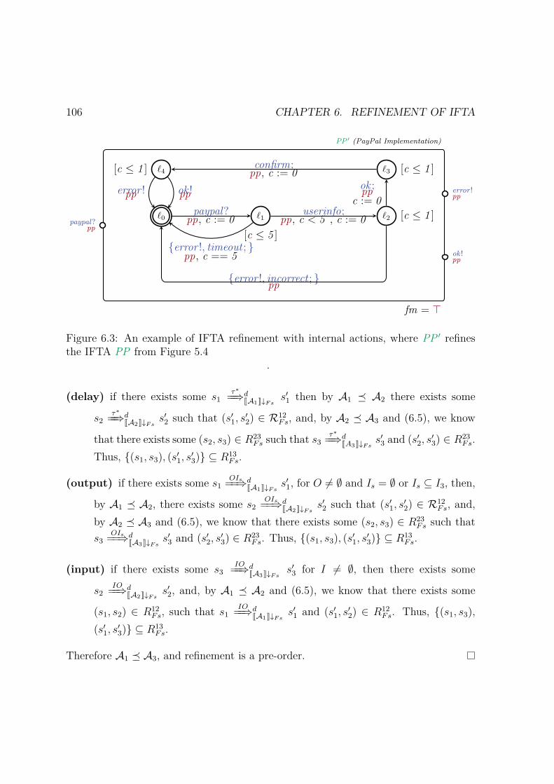
106 CHAPTER 6. REFINEMENT OF IFTA
ℓ0 ℓ1
[c ≤ 5 ]
ℓ2 [c ≤ 1 ]
ℓ3 [c ≤ 1 ]ℓ4[c ≤ 1 ]
paypal?pp, c := 0
error !, timeout ; pp, c == 5
userinfo;pp, c < 5 , c := 0
ok ;pp
c := 0
confirm;pp, c := 0
error !pp ok !pp
error !, incorrect ; pp
paypal?pp
error !pp
ok !pp
PP ′ (PayPal Implementation)
fm = ⊤
Figure 6.3: An example of IFTA refinement with internal actions, where PP ′ refinesthe IFTA PP from Figure 5.4
.
(delay) if there exists some s1τ∗==⇒dJA1 K↓Fs
s′1 then by A1 ⪯ A2 there exists some
s2τ∗==⇒dJA2 K↓Fs
s′2 such that (s′1, s′2) ∈ R12
Fs, and, by A2 ⪯ A3 and (6.5), we know
that there exists some (s2, s3) ∈ R23Fs such that s3
τ∗==⇒dJA3 K↓Fs
s′3 and (s′2, s′3) ∈ R23
Fs.Thus, (s1, s3), (s′1, s′3) ⊆ R13
Fs.
(output) if there exists some s1OIs==⇒dJA1 K↓Fs
s′1, for O = ∅ and Is = ∅ or Is ⊆ I3, then,
by A1 ⪯ A2, there exists some s2OIs==⇒dJA2 K↓Fs
s′2 such that (s′1, s′2) ∈ R12
Fs, and,by A2 ⪯ A3 and (6.5), we know that there exists some (s2, s3) ∈ R23
Fs such thats3
OIs==⇒dJA3 K↓Fss′3 and (s′2, s
′3) ∈ R23
Fs. Thus, (s1, s3), (s′1, s′3) ⊆ R13Fs.
(input) if there exists some s3IO==⇒dJA3 K↓Fs
s′3 for I = ∅, then there exists some
s2IO==⇒dJA2 K↓Fs
s′2, and, by A1 ⪯ A2 and (6.5), we know that there exists some
(s1, s2) ∈ R12Fs, such that s1
IO==⇒dJA1 K↓Fs
s′1 and (s′1, s′2) ∈ R12
Fs. Thus, (s1, s3),(s′1, s
′3) ⊆ R13
Fs.
Therefore A1 ⪯ A3, and refinement is a pre-order.

6.2. REFINEMENT 107
In order to be compositional, refinement must be congruent with respect to IFTAoperations, i.e., product and synchronization. However, stronger pre-conditions arerequired to ensure congruency for both operations.
In both cases the problem arises with feature model refinement. In the case ofproduct, let us consider three automata A1,A2 and B such that A1 ⪯ A2. We want toensure that A1 ×B ⪯ A2 ×B holds. The problem is that A1 and B can share featuresas well as A2 and B. Thus, we can not infer how each product will affect the resultingfeature model. As an example, consider the following arbitrary feature models,
Jfm1KF1 = f1, f2, f3, f1, f3, f3Jfm2KF2 = f1, f2, f1, JfmB KFB = f1, f2, f3, f4
with F1 = f1, f2, f3, F2 = f1, f2, and FB = f1, f2, f3, f4. We have that Jfm1KF1|F2=Jfm2KF2 , thus fm1 ⊑ fm2. However, when we do the corresponding feature model
conjunctions (as in the product), we have that Jfm1 ∧ fmB KF1B = f1, f2, f3 andJfm2 ∧ fmB KF2B = f1, f2, f3, f4. Thus, we have that
Jfm1 ∧ fmB KF1B |F2∪FB= f1, f2, f3 = Jfm2 ∧ fmB KF2B
and fm1B ⊑ fm2B.In order to guarantee that refinement is congruent with respect to product we fix
the assumption that neither A1 and B, nor A2 and B share any features.
6.2.3 Theorem (⪯ congruence w.r.t. ×). For any grounded IFTA A1, A2, andB, such that Ai and B have disjoint set of features, for i = 1, 2, if A1 ⪯ A2, thenA1 ×B ⪯ A2 ×B.
Proof. Let us consider first feature model refinement. First, by fm1 ⊑ fm2 we havethat F1 ⊇ F2, and therefore F1 ∪ FB ⊇ F2 ∪ FB. Now, we want to show thatJfm1 ∧ fmB KF1∪FB |F2∪FB
= Jfm2 ∧ fmB KF2∪FB . According to the semantics of a featureexpression, and because F1 ∩ FB = F2 ∩ FB = ∅, we have the following equivalences.
Jfm1 ∧ fmB KF1∪FB |F2∪FB= (Fs1 ∩ F2) ∪ FsB | Fs1 ⊆ F1, FsB ⊆ FB,
Fs1 |= fm1 andFsB |= FB
(6.6)
Jfm2 ∧ fmB KF2∪FB = Fs2 ∪ FsB | Fs2 ⊆ F2, FsB ⊆ FB,
Fs2 |= fm2 and FsB |= FB(6.7)
108 CHAPTER 6. REFINEMENT OF IFTA
By fm1 ⊑ fm2 we know that every Fs1 ∩ F2 such that Fs1 ⊆ F1 and Fs1 |= fm1
are exactly all the sets Fs2 ⊆ F2 such that Fs2 |= fm2. Therefore, equation (6.6) isequivalent to (6.7), and fm1B ⊑ fm2B.
Now, let us consider behavioral refinement. Assume that ∀ Fs ∈ Jfm1KF1 ,
R12Fs ⊆ St1 × St2, with (s01 , s02) ∈ R12
Fs
is the refinement relation for A1 ⪯ A2.We want to show that, for all Fs ∈ Jfm1B KF1B , there exists a relation R1B2B
Fs ,such that (s01b , s02b) ∈ R1B2B
Fs , and each (s1b, s2b) ∈ R1B2BFs satisfies the conditions in
Definition 6.2.3.For any Fs ∈ Jfm1B KF1B , we have that:
(delay) if there exists some ⟨(l1, lb), ηA1B⟩ τ∗==⇒dJA1×BK↓Fs
⟨(l′1, l′b), ηA′1B′⟩, by definition
of IFTA product, there exists some ⟨l1, ηA1⟩ τ∗==⇒dJA1 K↓Fs
⟨l′1, ηA′1⟩ and there ex-
ists some ⟨lb, ηB⟩τ∗==⇒dJBK↓Fs
⟨l′b, ηB′⟩; by A1 ⪯ A2, we have that there exists
some ⟨l2, ηA2⟩ τ∗==⇒dJA2 K↓Fs
⟨l′2, ηA′2⟩, such that (⟨l1, ηA1⟩, ⟨l2, ηA2⟩) ∈ R12
Fs\FB1 and
(⟨l′1, ηA′1⟩, ⟨l′2, ηA
′2⟩) ∈ R12
FS\FB. Thus, by definition of IFTA product, there ex-
ists some ⟨(l2, lb), ηA2B⟩ τ∗==⇒dJA2×BK↓Fs
⟨(l′2, l′b), ηA′2B′⟩, such that (⟨(l1, lb), ηA1B⟩,
⟨(l2, lb), ηA2B⟩) ∈ R1B2BFs , and (⟨(l′1, l′b), ηA
′1B′⟩, ⟨(l′2, l′b), ηA
′2B′⟩) ∈ R1B2B
Fs .
(output) if there exists some ⟨(l1, lb), ηA1B⟩ OI==⇒dJA1×BK↓Fs
⟨(l′1, l′b), ηA′1B′⟩, we have to
consider three cases depending on which automaton takes the observable trans-ition: 1) independent transition from A1, i.e., OI ⊆ O1 ∪ I2; 2) independenttransition from B, i.e., OI ⊆ OB ∪ IB; or 3) simultaneous transition from A1
and B, i.e., OI ⊆ O1B ∪ I2B. Here we consider case 1) only; the reasoningis analogous for the other cases. In this case, by definition of IFTA product,we have that there exists some ⟨l1, ηA1⟩ OI
==⇒ dJA1 K↓Fs⟨l′1, ηA
′1⟩ and there exists
some ⟨lb, ηB⟩τ∗==⇒dJBK↓Fs
⟨l′b, ηB′⟩. Then, by A1 ⪯ A2, we have that there exists
some ⟨l2, ηA2⟩ OI==⇒ dJA2 K↓Fs
⟨l′2, ηA2⟩ such that (⟨l1, ηA1⟩, ⟨l2, ηA2⟩) ∈ R12FS\FB
and(⟨l′1, ηA
′1⟩, ⟨l′2, ηA
′2⟩) ∈ R12
FS\FB. Thus, by definition of IFTA product, we have
1Note that Fs ∈ Jfm1B K, and that Fs \FB ∈ Jfm1K since F1 ∩ FB = ∅. Thus, we use JA1K ↓Fs
instead of JA1K ↓Fs\FBsince this results in the same automaton. Similarly, we use JA2K ↓Fs instead
of JA2K ↓Fs\FB.
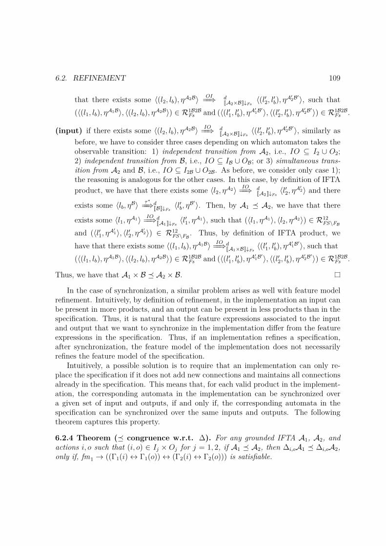
6.2. REFINEMENT 109
that there exists some ⟨(l2, lb), ηA2B⟩ OI==⇒ dJA2×BK↓Fs
⟨(l′2, l′b), ηA′2B′⟩, such that
(⟨(l1, lb), ηA1B⟩, ⟨(l2, lb), ηA2B⟩) ∈ R1B2BFs and (⟨(l′1, l′b), ηA
′1B′⟩, ⟨(l′2, l′b), ηA
′2B′⟩) ∈ R1B2B
Fs .
(input) if there exists some ⟨(l2, lb), ηA2B⟩ IO==⇒ dJA2×BK↓Fs
⟨(l′2, l′b), ηA′2B′⟩, similarly as
before, we have to consider three cases depending on which automaton takes theobservable transition: 1) independent transition from A2, i.e., IO ⊆ I2 ∪ O2;2) independent transition from B, i.e., IO ⊆ IB ∪ OB; or 3) simultaneous trans-ition from A2 and B, i.e., IO ⊆ I2B ∪ O2B. As before, we consider only case 1);the reasoning is analogous for the other cases. In this case, by definition of IFTAproduct, we have that there exists some ⟨l2, ηA2⟩ IO
==⇒ dJA2 K↓Fs⟨l′2, ηA
′2⟩ and there
exists some ⟨lb, ηB⟩τ∗==⇒dJBK↓Fs
⟨l′b, ηB′⟩. Then, by A1 ⪯ A2, we have that there
exists some ⟨l1, ηA1⟩ IO==⇒dJA1 K↓Fs
⟨l′1, ηA1⟩, such that (⟨l1, ηA1⟩, ⟨l2, ηA2⟩) ∈ R12FS\FB
and (⟨l′1, ηA′1⟩, ⟨l′2, ηA
′2⟩) ∈ R12
FS\FB. Thus, by definition of IFTA product, we
have that there exists some ⟨(l1, lb), ηA1B⟩ IO==⇒dJA1×BK↓Fs
⟨(l′1, l′b), ηA′1B′⟩, such that
(⟨(l1, lb), ηA1B⟩, ⟨(l2, lb), ηA2B⟩) ∈ R1B2BFs and (⟨(l′1, l′b), ηA
′1B′⟩, ⟨(l′2, l′b), ηA
′2B′⟩) ∈ R1B2B
Fs .
Thus, we have that A1 × B ⪯ A2 × B.
In the case of synchronization, a similar problem arises as well with feature modelrefinement. Intuitively, by definition of refinement, in the implementation an input canbe present in more products, and an output can be present in less products than in thespecification. Thus, it is natural that the feature expressions associated to the inputand output that we want to synchronize in the implementation differ from the featureexpressions in the specification. Thus, if an implementation refines a specification,after synchronization, the feature model of the implementation does not necessarilyrefines the feature model of the specification.
Intuitively, a possible solution is to require that an implementation can only re-place the specification if it does not add new connections and maintains all connectionsalready in the specification. This means that, for each valid product in the implement-ation, the corresponding automata in the implementation can be synchronized overa given set of input and outputs, if and only if, the corresponding automata in thespecification can be synchronized over the same inputs and outputs. The followingtheorem captures this property.
6.2.4 Theorem (⪯ congruence w.r.t. ∆). For any grounded IFTA A1, A2, andactions i, o such that (i, o) ∈ Ij × Oj for j = 1, 2, if A1 ⪯ A2, then ∆i,oA1 ⪯ ∆i,oA2,only if, fm1 → ((Γ1(i) ↔ Γ1(o)) ↔ (Γ2(i) ↔ Γ2(o))) is satisfiable.

110 CHAPTER 6. REFINEMENT OF IFTA
Proof. Let us consider feature model refinement. First, by fm1 ⊑ fm2 and because ∆does not affect features, we have that F∆1 = F1 ⊇ F2 = F∆2. Second, we want to showthat Jfm1 ∧ (Γ1(i) ↔ Γ1(o))KF∆1|F∆2
= Jfm2 ∧ (Γ2(i) ↔ Γ2(o))KF∆2 . According to thesemantics of a feature expression, we have the following equivalences:
Jfm1 ∧ (Γ1(i) ↔ Γ1(o))KF∆1|F∆2= FS 1 ∩ F∆2 | FS 1 ⊆ F∆1,
FS 1 |= fm1, andFS 1 |= (Γ1(i) ↔ Γ1(o))
(6.8)
Jfm2 ∧ (Γ2(i) ↔ Γ2(o))KF∆2 = FS 2 | FS 2 ⊆ F∆2,
FS 2 |= fm2, andFS 2 |= (Γ2(i) ↔ Γ2(o))
(6.9)
By fm1 ⊑ fm2 we know that all sets FS 1 ∩ F∆2 such that FS 1 ⊆ F∆1 and FS 1 |= fm1,where F∆1 = F1, are exactly all the sets FS 2 ⊆ F∆2 such that FS 2 |= fm2. In addition,we know that FS1 |= Γ1(i) ↔ Γ1(o), if and only if, FS1 |= Γ2(i) ↔ Γ2(o), and becauseF∆1 ⊇ F∆2, we have that FS1 |= Γ2(i) ↔ Γ2(o) ⇐⇒ FS1 ∩ F∆2 |= Γ2(i) ↔ Γ2(o).Therefore, equation (6.8) is equivalent to (6.9), and fm∆1 ⊑ fm∆2.
Now, let us consider behavioural refinement. Assume that for all FS ∈ Jfm1KF1 ,
R12FS ⊆ St1 × St2, with (s01 , s02) ∈ R12
FS
is the refinement relation for A1 ⪯ A2.We want to show that for all FS ∈ Jfm∆1KF∆1 , there exists a relation R∆1∆2
FS ,such that (s0∆1
, s0∆2) ∈ R∆1∆2
FS , and each (s∆1, s∆2) ∈ R∆1∆2FS satisfies the conditions in
Definition 6.2.3 as follows.For each FS ∈ Jfm∆1KF∆1 , we have that:
(delay) if there exists some ⟨l∆1, η∆1⟩ τ∗
==⇒dJ∆A1 K↓FS⟨l′∆1, η
∆1′⟩, we have to consider twocases regarding the nature of this transition in A1 ↓FS 2. That is, this trans-ition can correspond to two kinds of (sequences of) transitions: 1) includes, ifany, only internal transitions – thus, the same transition existed in JA1K ↓FS ;and 2) includes at least one transition with i and o in its set of actions – thus,we can decompose this transition in smaller cases. In case 1), this transitioncorresponds to a (possible sequence of internal) transition(s) in A1 ↓FS , andsince these transitions are not affected by ∆, we have that there exists some
2Projection of IFTA is defined analogous to projection of IFTS

6.2. REFINEMENT 111
⟨l∆1, η∆1⟩ τ∗
==⇒dJA1 K↓FS⟨l′∆1, η
∆1′⟩. Then by A1 ⪯ A2, we have that there exists
some ⟨l2, η2⟩τ∗==⇒dJA2 K↓FS
⟨l′2, η2′⟩, such that (⟨l∆1, η
∆1⟩, ⟨l2, η2⟩) ∈ R12FS and (⟨l′∆1,
η∆1′⟩, ⟨l′2, η2′⟩) ∈ R12
FS . Therefore, since the transition in A2 ↓FS consists onlyof internal transitions, if any, then there exists some ⟨l2, η2⟩
τ∗==⇒dJ∆A2 K↓FS
⟨l′2, η2′⟩,
such that (⟨l∆1, η∆1⟩, ⟨l2, η2⟩) ∈ R∆1∆2
FS , and (⟨l′∆1, η∆1′⟩, ⟨l′2, η2
′⟩) ∈ R∆1∆2FS . In
case 2), this transition corresponds to a sequence of transitions in A1 ↓FS , whichcontains internal transitions, if any. Let us assume that, without loss of general-ity, there is only one transition with i and o in its set of actions. That is, thereexists some
l∆1τ=⇒ A1↓FS
lii,o−−−→ A1↓FS
ljτ=⇒ A1↓FS
l′∆1
where lτ=⇒ A l′ is defined as a sequence of one or more internal transitions
lτ−→ A l1 . . . ln
τ−→ A l′. Then, by JA1K there exists some
⟨l∆1, η∆1⟩ i,o
===⇒ d′JA1 K↓FS⟨lj, η∆1
j ⟩ d′′==⇒ JA1 K↓FS
⟨l′∆1, η∆1′⟩
such that d = d′ + d′′. Then, because A1 ⪯ A2, and because i, o ⊆ Im × Om form = 1, 2, this is, i,o
===⇒ d′JA1 K↓FScorresponds to an output transition, we have that
there exists some
⟨l2, η2⟩i,o===⇒ d′JA2 K↓FS
⟨lk, η2k⟩d′′==⇒ JA2 K↓FS
⟨l′2, η2′⟩
such that (⟨l∆1, η∆1⟩, ⟨l2, η2⟩) ∈ R12
FS , (⟨lj, η∆1j ⟩, ⟨lk, η2k⟩) ∈ R12
FS and (⟨l′∆1, η∆1′⟩,
⟨l′2, η2′⟩) ∈ R12
FS . Then, by definition of ∆, there exists some
⟨l2, η2⟩i,o===⇒ dJ∆A2 K↓FS
⟨l′2, η2′⟩
such that (⟨l∆1, η∆1⟩, ⟨l2, η2⟩) ∈ R∆1∆2
FS , and (⟨l′∆1, η∆1′⟩, ⟨l′2, η2
′⟩) ∈ R∆1∆2FS .
(output) if there exists some ⟨l∆1, η∆1⟩ OI
==⇒ dJ∆A1 K↓FS⟨l′∆1, η
∆1′⟩, we can decomposethis transition as
⟨l∆1, η∆1⟩ τ∗
==⇒dJ∆A1 K↓FS⟨lj, η∆1
j ⟩ IO−−→ J∆A1 K↓FS⟨l′∆1, η
∆1′⟩
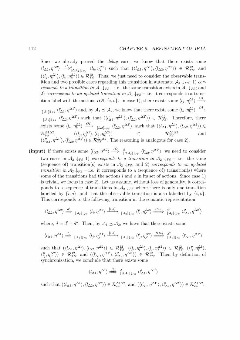
112 CHAPTER 6. REFINEMENT OF IFTA
Since we already proved the delay case, we know that there exists some⟨l∆2, η
∆2⟩ τ∗==⇒dJ∆A2 K↓FS
⟨lk, η∆2k ⟩ such that (⟨l∆1, η
∆1⟩, ⟨l∆2, η∆2⟩) ∈ R12
FS , and(⟨lj, η∆1
j ⟩, ⟨lk, η∆2k ⟩) ∈ R12
FS . Thus, we just need to consider the observable trans-ition and two possible cases regarding this transition in automata A1 ↓FS : 1) cor-responds to a transition in A1 ↓FS – i.e., the same transition exists in A1 ↓FS ; and2) corresponds to an updated transition in A1 ↓FS – i.e. it corresponds to a trans-ition label with the actions IO∪i, o. In case 1), there exists some ⟨lj, η∆1
j ⟩ OI−−→
JA1 K↓FS⟨l′∆1, η
∆1′⟩ and, by A1 ⪯ A2, we know that there exists some ⟨lk, η∆2k ⟩ OI−−→
JA2 K↓FS⟨l′∆2, η
∆2′⟩ such that (⟨l′∆1, η∆1′⟩, ⟨l′∆2, η
∆2′⟩) ∈ R12FS . Therefore, there
exists some ⟨lk, η∆2k ⟩ OI−−→ J∆2K↓FS
⟨l′∆2, η∆2′⟩, such that (⟨l∆1, η
∆1⟩, ⟨l∆2, η∆2⟩) ∈
R∆1∆2FS , (⟨lj, η∆1
j ⟩, ⟨lk, η∆2k ⟩) ∈ R∆1∆2
FS , and(⟨l′∆1, η
∆1′⟩, ⟨l′∆2, η∆2′⟩) ∈ R∆1∆2
FS . The reasoning is analogous for case 2).
(input) if there exists some ⟨l∆2, η∆2⟩ IO
==⇒ dJ∆A2 K↓FS⟨l′∆2, η
∆2′⟩, we need to considertwo cases in A2 ↓FS 1) corresponds to a transition in A2 ↓FS – i.e. the same(sequence of) transition(s) exists in A2 ↓FS ; and 2) corresponds to an updatedtransition in A2 ↓FS – i.e. it corresponds to a (sequence of) transition(s) wheresome of the transitions had the actions i and o in its set of actions. Since case 1)is trivial, we focus in case 2). Let us assume, without loss of generality, it corres-ponds to a sequence of transitions in A2 ↓FS where there is only one transitionlabelled by i, o, and that the observable transition is also labelled by i, o.This corresponds to the following transition in the semantic representation:
⟨l∆2, η∆2⟩ d′
=⇒ JA2 K↓FS⟨li, η∆2
i ⟩ i,o−−−→ JA2 K↓FS⟨l′i, η∆2
i′ ⟩ IOio===⇒ d′′JA2 K↓FS
⟨l′∆2, η∆2′⟩
where, d = d′ + d′′. Then, by A1 ⪯ A2, we have that there exists some
⟨l∆1, η∆1⟩ d′
=⇒ JA1 K↓FS⟨lj, η∆1
j ⟩ i,o−−−→ JA1 K↓FS⟨l′j, η∆2
j′ ⟩ IOio===⇒ d′′JA1 K↓FS
⟨l′∆1, η∆1′⟩
such that (⟨l∆1, η∆1⟩, ⟨l∆2, η
∆2⟩) ∈ R12FS , (⟨li, η∆1
i ⟩, ⟨lj, η∆2j ⟩) ∈ R12
FS , (⟨l′i, η∆1i′ ⟩,
⟨l′j, η∆2j′ ⟩) ∈ R12
FS , and (⟨l′∆1, η∆1′⟩, ⟨l′∆2, η
∆2′⟩) ∈ R12FS . Then by definition of
synchronization, we conclude that there exists some
⟨l∆1, η∆1⟩ IO
==⇒ dJ∆A1 K↓FS⟨l′∆1, η
∆1′⟩
such that (⟨l∆1, η∆1⟩, ⟨l∆2, η
∆2⟩) ∈ R∆1∆2FS , and (⟨l′∆1, η
∆1′⟩, ⟨l′∆2, η∆2′⟩) ∈ R∆1∆2
FS .
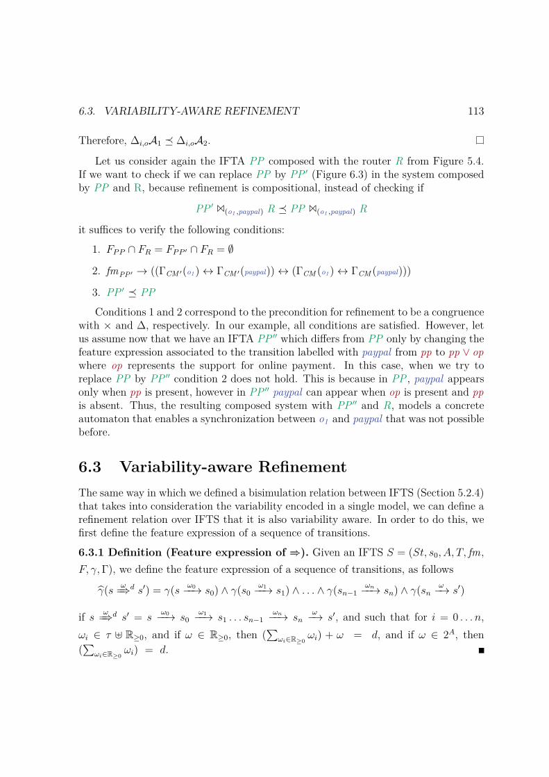
6.3. VARIABILITY-AWARE REFINEMENT 113
Therefore, ∆i,oA1 ⪯ ∆i,oA2.
Let us consider again the IFTA PP composed with the router R from Figure 5.4.If we want to check if we can replace PP by PP ′ (Figure 6.3) in the system composedby PP and R, because refinement is compositional, instead of checking if
PP ′ 1(o1 ,paypal) R ⪯ PP 1(o1 ,paypal) R
it suffices to verify the following conditions:
1. FPP ∩ FR = FPP ′ ∩ FR = ∅
2. fmPP ′ → ((ΓCM ′(o1) ↔ ΓCM ′(paypal)) ↔ (ΓCM (o1) ↔ ΓCM (paypal)))
3. PP ′ ⪯ PP
Conditions 1 and 2 correspond to the precondition for refinement to be a congruencewith × and ∆, respectively. In our example, all conditions are satisfied. However, letus assume now that we have an IFTA PP ′′ which differs from PP only by changing thefeature expression associated to the transition labelled with paypal from pp to pp ∨ opwhere op represents the support for online payment. In this case, when we try toreplace PP by PP ′′ condition 2 does not hold. This is because in PP , paypal appearsonly when pp is present, however in PP ′′ paypal can appear when op is present and ppis absent. Thus, the resulting composed system with PP ′′ and R, models a concreteautomaton that enables a synchronization between o1 and paypal that was not possiblebefore.
6.3 Variability-aware RefinementThe same way in which we defined a bisimulation relation between IFTS (Section 5.2.4)that takes into consideration the variability encoded in a single model, we can define arefinement relation over IFTS that it is also variability aware. In order to do this, wefirst define the feature expression of a sequence of transitions.
6.3.1 Definition (Feature expression of =⇒). Given an IFTS S = (St, s0, A, T, fm,
F, γ,Γ), we define the feature expression of a sequence of transitions, as follows
γ(sω=⇒d s′) = γ(s
ω0−−→ s0) ∧ γ(s0ω1−−→ s1) ∧ . . . ∧ γ(sn−1
ωn−−→ sn) ∧ γ(snω−→ s′)
if sω=⇒d s′ = s
ω0−−→ s0ω1−−→ s1 . . . sn−1
ωn−−→ snω−→ s′, and such that for i = 0 . . . n,
ωi ∈ τ ⊎ R≥0, and if ω ∈ R≥0, then (∑
ωi∈R≥0ωi) + ω = d, and if ω ∈ 2A, then
(∑
ωi∈R≥0ωi) = d.
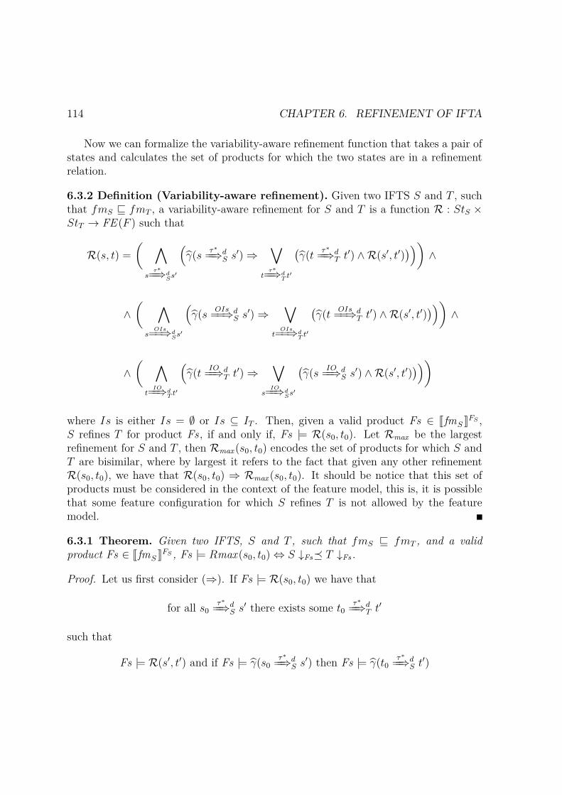
114 CHAPTER 6. REFINEMENT OF IFTA
Now we can formalize the variability-aware refinement function that takes a pair ofstates and calculates the set of products for which the two states are in a refinementrelation.
6.3.2 Definition (Variability-aware refinement). Given two IFTS S and T , suchthat fmS ⊑ fmT , a variability-aware refinement for S and T is a function R : StS ×StT → FE (F ) such that
R(s, t) =
( ∧s
τ∗==⇒dSs
′
(γ(s
τ∗==⇒d
S s′) ⇒∨
tτ∗==⇒d
T t′
(γ(t
τ∗==⇒d
T t′) ∧R(s′, t′))))
∧
∧( ∧
sOIs==⇒d
Ss′
(γ(s
OIs==⇒d
S s′) ⇒∨
tOIs==⇒d
T t′
(γ(t
OIs==⇒d
T t′) ∧R(s′, t′))))
∧
∧( ∧
tIO==⇒d
T t′
(γ(t
IO==⇒d
T t′) ⇒∨
sIO==⇒d
Ss′
(γ(s
IO==⇒d
S s′) ∧R(s′, t′))))
where Is is either Is = ∅ or Is ⊆ IT . Then, given a valid product Fs ∈ JfmS KFS ,S refines T for product Fs , if and only if, Fs |= R(s0, t0). Let Rmax be the largestrefinement for S and T , then Rmax (s0, t0) encodes the set of products for which S andT are bisimilar, where by largest it refers to the fact that given any other refinementR(s0, t0), we have that R(s0, t0) ⇒ Rmax (s0, t0). It should be notice that this set ofproducts must be considered in the context of the feature model, this is, it is possiblethat some feature configuration for which S refines T is not allowed by the featuremodel.
6.3.1 Theorem. Given two IFTS, S and T , such that fmS ⊑ fmT , and a validproduct Fs ∈ JfmS KFS , Fs |= Rmax (s0, t0) ⇔ S ↓Fs⪯ T ↓Fs .
Proof. Let us first consider (⇒). If Fs |= R(s0, t0) we have that
for all s0τ∗==⇒d
S s′ there exists some t0τ∗==⇒d
T t′
such that
Fs |= R(s′, t′) and if Fs |= γ(s0τ∗==⇒d
S s′) then Fs |= γ(t0τ∗==⇒d
S t′)

6.4. DISCUSSION 115
In other words, for all transitions s0τ∗==⇒d
S s′ that exist in a product Fs , i.e., exist
in S ↓Fs , there is at least a transition t0τ∗==⇒d
T t′ that exist in T ↓Fs , and becauseFs |= R(s′, t′), then this is also valid for transitions with s’ and t’ as origin states.This is exactly condition 6.1 in Definition 6.2.3. The reasoning is analogous for theother two cases, i.e., transitions labelled with OIs and IO. Thus, we conclude that(s0, t0) ∈ RFs , where RFs is a refinement relation for S ↓Fs⪯ T ↓Fs .
Let us now consider (⇐). If S ↓Fs⪯ T ↓Fs for a valid product Fs ∈ JfmS KFS , thenlet RFs be a refinement relation for S ↓Fs⪯ T ↓Fs , such that (s0, t0) ∈ RFs . As before,this means that for all (s, t) ∈ RFs , including (s0, t0), we have that
for all s τ∗==⇒d
S↓Fss′ there exists some t
τ∗==⇒d
T↓Fst′ such that (s′, t′) ∈ RFs
and since this is a projection over Fs , we have that
if Fs |= γ(s0τ∗==⇒d
S s′) then Fs |= γ(t0τ∗==⇒d
S t′)
The reasoning for the other two cases from Definition 6.2.3 is analogous. Thus, wehave that Fs |= R(s0, t0).
6.4 DiscussionFirst we proposed a refinement relation for families of timed automata modelled asInterface Featured Timed Automata. Since each IFTA can be seen as: 1) a featuremodel, which determines a set of valid feature combinations; and 2) a set of concreteautomata, where each of the concrete automata is determined by a valid set of features;we separated the notion of IFTA refinement into variability refinement and behavioralrefinement. Furthermore, we decomposed IFTA resorting to other formalisms anddefine the corresponding notion of refinement, namely Interface Featured TransitionSystem (IFTS) and Interface Transition Systems (ITS).
Additionally, we proposed a refinement function over IFTS that takes into accountthe variability encoded in the model. Thus it is possible to verify over a single model,the set of products for which an IFTS refines another.
The refinement relation proposed here is a pre-order and congruent with respectto IFTA product and synchronization, meaning refinement is compositional. However,in order to be congruent stronger conditions are required to hold. In particular, theimplementation can only replace the specification in a composed environment, if 1)neither the implementation nor the specification may share features with the environ-ment; and 2) the implementation does not add new interface connections and maintainsall connections of the specification.

116 CHAPTER 6. REFINEMENT OF IFTA
Although the requirement of not allowing new connections and maintain existingones is reasonable, it can be too strict. For example, in alignment with the notionof ITS refinement, which allows to incorporate new behavior through new inputs, itmight be desirable to incorporate new behavior in terms of new features. This waythe example of PP ′′, introduced in Section 6.2.3, can be considered a refinement ofPP . In fact, in [53], de Alfaro et. al. requires only that no new connections withthe environment are made, while some connections can be lost. However, this is notsufficient to ensure that IFTA refinement is compositional. In this sense, as future workwe would like to explore and formalize other notions of refinement and how these canaffect the properties that one can expect from a refinement. For example, in the caseof behavioural refinement, we could have defined that A refines B, if and only if, forevery feature selection Fs in fmB (instead of fmA), JAK ↓Fs ⪯ JBK ↓Fs . The advantageis that we can now incorporate behaviour in terms of new features. However, on theone hand, this requires that fmA contains at least all feature selections allowed by fmB,meaning fmA can not incorporate mandatory features. On the other, it can be tooflexible, since we can not account for how the system will behave for new variability.

Chapter 7
Variability and Coordination
In Section 4.3 we presented the Reo coordination language. A main advantage of Reois that synchronization is propagated through connectors by composition. Thus, wecan use very simple primitive channels and nodes to build large complex coordinationprotocols. In alignment with our work, we would like as well to have variability beingpropagated through connectors by means of composition. The aim is to define variableand generic coordination protocols that adapt to the variability of the components theycoordinate simply by linking ports that are variable. Towards this goal, we model Reoconnectors as IFTA.
Intuitively, given a set of components with variable ports, we want to define a co-ordination protocol for the entire family parametrized by features, such that differentfeature selections determine the different protocols. The protocols themselves merelydefine how variability propagates through their ends, while the actual variability isgiven by the variability of the components being coordinated. The composition mech-anism for IFTA determines what are the valid feature selections, if any, for the protocoland for the entire composed system.
Since components have their own variability, the propagation could either be suc-cessful, implying that there is at least one product derivable from the composed system;or could fail due to a contradiction on the variability constraints of the componentsbeing coordinated. In the latter case, the envisaged set of components cannot be co-ordinated in such a way and thus there is no product derivable from the resultingcomposed system.
Chapter organization. Section 7.1 presents two approaches to model some com-monly used Reo connectors as IFTA. Section 7.2 illustrates with an example howvariable connectors from both approaches are combined to model a complex coordina-tion protocol. Finally, Section 7.3 discusses some benefits of this semantics and some
117
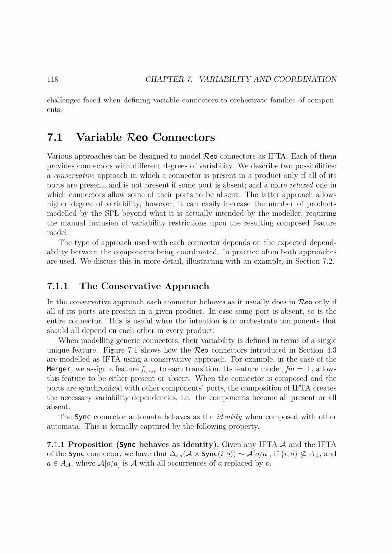
118 CHAPTER 7. VARIABILITY AND COORDINATION
challenges faced when defining variable connectors to orchestrate families of compon-ents.
7.1 Variable Reo ConnectorsVarious approaches can be designed to model Reo connectors as IFTA. Each of themprovides connectors with different degrees of variability. We describe two possibilities:a conservative approach in which a connector is present in a product only if all of itsports are present, and is not present if some port is absent; and a more relaxed one inwhich connectors allow some of their ports to be absent. The latter approach allowshigher degree of variability, however, it can easily increase the number of productsmodelled by the SPL beyond what it is actually intended by the modeller, requiringthe manual inclusion of variability restrictions upon the resulting composed featuremodel.
The type of approach used with each connector depends on the expected depend-ability between the components being coordinated. In practice often both approachesare used. We discuss this in more detail, illustrating with an example, in Section 7.2.
7.1.1 The Conservative ApproachIn the conservative approach each connector behaves as it usually does in Reo only ifall of its ports are present in a given product. In case some port is absent, so is theentire connector. This is useful when the intention is to orchestrate components thatshould all depend on each other in every product.
When modelling generic connectors, their variability is defined in terms of a singleunique feature. Figure 7.1 shows how the Reo connectors introduced in Section 4.3are modelled as IFTA using a conservative approach. For example, in the case of theMerger, we assign a feature fi1 i2o to each transition. Its feature model, fm = ⊤, allowsthis feature to be either present or absent. When the connector is composed and theports are synchronized with other components’ ports, the composition of IFTA createsthe necessary variability dependencies, i.e. the components become all present or allabsent.
The Sync connector automata behaves as the identity when composed with otherautomata. This is formally captured by the following property.
7.1.1 Proposition (Sync behaves as identity). Given any IFTA A and the IFTAof the Sync connector, we have that ∆i,a(A× Sync(i, o)) ∼ A[o/a], if i, o ⊆ AA, anda ∈ AA, where A[o/a] is A with all occurrences of a replaced by o.

7.1. VARIABLE REO CONNECTORS 119
ℓ0i , ofio
i?fio
o!fio
fm = ⊤
(a) Sync
ℓ0i1fi1 i2
i2fi1 i2
i1 ?fi1 i2
i2 ?fi1 i2
fm = ⊤
(b) AsyncDrain
ℓ0i1 , i2fi1 i2
i1 ?fi1 i2
i2 ?fi1 i2
fm = ⊤
(c) SyncDrain
ℓ0 ℓ1
ifioofio
i?fio
o!fio
fm = ⊤
(d) FIFO1
ℓ0i , o1 , o2
fio1o2
i?fio1 o2
o1 !fio1 o2
o2 !fio1 o2
fm = ⊤
(e) Replicator
ℓ0i1 , i2 , o
fi1 i2o
i1 ?fi1 i2 o
i2 ?fi1 i2 o
o!fi1 i2 o
fm = ⊤
(f) Join
ℓ0i1 , ofi1 i2o
i2 , ofi1 i2o
fm = ⊤
i1 ?fi1 i2 o
i2 !fi1 i2 o
o!fi1 i2 o
(g) Merger
ℓ0i , oifio1o2
i , o2fio1o2
i?fio1 o2
o1 !fio1 o2
o2 !fio1 o2
fm = ⊤
(h) Router
Figure 7.1: Example of Reo connectors modelled as IFTA using the conservative ap-proach.
Proof. First, let us notice that because of how we define bisimulation between IFTA,we need to make the following updates to prove bisimilarity:
– fmA[o/a] = fmA ∧ (fio ↔ ΓA(a))
– γA[o/a](ℓg,ω,r−−−→A[o/a] ℓ
′) = γA(ℓg,ω[a/o],r−−−−−−→A ℓ′) ∧ fio, if o ∈ ω
– FA[o/a] = FA ∪ fio

120 CHAPTER 7. VARIABILITY AND COORDINATION
– ΓA[o/a](o) = ΓSync(o)
However, in practice, this is not necessary, since in essence these updates are done ontop of a counterfeit feature that would be added if A is composed with Sync, i.e. fio ,and the restrictions added do not affect the set of products allowed by A, they simplyextend the set of features with fio .
For simplicity, let AS = (A× Sync(i, o)), and A′ = ∆i,a(AS). Let us note that theset of edges in A′ is defined as follows
TA′ =(ℓ1, ℓ0)g,ω,r−−−→AS
(ℓ′1, ℓ0) | i /∈ ω and a /∈ ω ∪ (1)
(ℓ1, ℓ0)g,ω\i,a,r−−−−−−−→ (ℓ′1, ℓ0) | (ℓ1, ℓ0)
g,ω,r−−−→AS(ℓ′1, ℓ0)
and i ∈ ω and a ∈ ω (2)
where ℓ0 is the initial and only location of Sync. Let F1 and F2 be the underlyingFTS of A′ and A[o/a], and note that R = (⟨(ℓ1, ℓ0), η⟩, ⟨ℓ1, η⟩) | ℓ1 ∈ SA[o/a] is abisimulation relating F1 and F2. Let (⟨(ℓ1, ℓ0), η⟩, ⟨ℓ1, η⟩) ∈ R. The proof for delaytransitions follows trivially from the fact that Inv(ℓ1, ℓ0) = Inv(ℓ1) for all ℓ1 ∈ SA[o/a].
Let us consider any action transition ⟨(ℓ1, ℓ0), η⟩ω−→ ⟨(ℓ′1, ℓ0), η′⟩ ∈ TF1 . If it comes
from an edge in (1), then there exists some ℓ1g,ω,r−−−→ ℓ′1 ∈ TA s .t . a ∈ ω, thus there
exists some ⟨ℓ1, η⟩ω−→ ⟨ℓ′1, η′⟩ ∈ TF2 ; if it comes from (2), then there exists some
ℓ1g,ω1,r−−−−→ ℓ′1 ∈ TA s .t . a ∈ ω1, thus there exists some ⟨ℓ1, η⟩
ω1[o/a]−−−−→ ⟨ℓ′1, η′⟩ ∈ TF2 , where
ω = ω1∪i, o\i, a = ω[o/a]. Conversely, if there exists some ⟨ℓ1, η⟩ω−→ ⟨ℓ′1, η′⟩ ∈ TF2
and o ∈ ω, then there exists some (ℓ1, ℓ0)g,ω,r−−−→ (ℓ′1, ℓ0) ∈ TAS
s .t . i /∈ ω ∧ a /∈ ω, thus
there exists some ⟨(ℓ1, ℓ0), η⟩ω−→ ⟨(ℓ′1, ℓ0), η′⟩ ∈ TF1 ; if o ∈ ω, then there exists some
(ℓ1, ℓ0)g,ω1∪o\a,r−−−−−−−−−→ (ℓ′1, ℓ0) ∈ TA′ , such that ω = ω1[o/a] = ω1 ∪ o \ a, thus there
exists some ⟨(ℓ1, ℓ0), ηω−→ ⟨(ℓ′1, ℓ0), η′⟩⟩ ∈ TF1 .
In both cases, we have γF1(⟨(ℓ1, ℓ0), η⟩ω−→ ⟨(ℓ′1, ℓ0), η′⟩) = γF2(⟨ℓ1, η⟩
ω−→ ⟨ℓ′1, η′⟩).Furthermore, fm ′
A = fmA[o/a].
7.1.2 The Relaxed ApproachWe propose now a more flexible model for Reo connectors in which some ports mightbe absent. This sort of flexibility is useful when the components being coordinated areindependent and do not always need to be present in the same product. By independent

7.1. VARIABLE REO CONNECTORS 121
we refer to the fact that they are variability independent, thus the components do notneed to be present when the others components connected to the protocol are present,nor absent if the others are absent. If such were the case, the conservative approach issuitable to model the coordination protocol.
ℓ0
i1 , i2 , ofi1 ∧ fi2 ∧ fo
i1 , ofi1 ∧ ¬fi2 ∧ fo
i2 , o¬fi1 ∧ fi2 ∧ fo
i1 ?fi1 ∧ fo
i2 ?fi2 ∧ fo
o!(fi1 ∨ fi2 ) ∧ fo
fm = (fi1 ∨ fi2 ) ↔ fo
(a) Join
ℓ0
i , o1 , o2fi∧ fo1 ∧ fo2
i , o1fi ∧ fo1 ∧ ¬fo2
i , o2fi∧ ¬fo1 ∧ fo2
i?fi ∧ (fo1 ∨ fo2 )
o1 !fi ∧ fo1
o2 !fi ∧ fo2
fm = fi ↔ (fo1 ∨ fo2 )
(b) Replicator
ℓ0
i1 , i2fi1 ∧ fi2
i1fi1 ∧ ¬fi2
i2¬fi1 ∧ fi2
i1 ?fi1
i2 ?fi2
fm = ⊤
(c) SyncDrain
ℓ0i1fi1
i2fi2
i1 ?fi1
i2 ?fi2
fm = ⊤
(d) AsyncDrain
ℓ0i , o1fi ∧ fo1
i , o2fi ∧ fo2
i?fi ∧ (fo1 ∨ fo2 )
o1 !fi ∧ fo1
o2 !fi ∧ fo2
fm = fi ↔ (fo1 ∨ fo2 )
(e) Router
ℓ0i1 , ofi1 ∧ fo
i2 , ofi2 ∧ fo
i1 ?fi1 ∧ fo
i2 !fi2 ∧ fo
o!fo ∧ (fi1 ∨ fi2 )
fm = (fi1 ∨ fi2 ) ↔ fo
(f) Merger
Figure 7.2: Example of Reo connectors modelled as IFTA using the relaxed approach.

122 CHAPTER 7. VARIABILITY AND COORDINATION
In practice, this only makes sense for some of the connectors introduced in Sec-tion 4.3. In particular, in the case of the Sync and FIFO1 connector, it does no makesense that only one of the ports is present.
In the case of Sync, whose aim is to synchronize two components, such that inform-ation flows from the input to the output, if one end is missing, the connector shouldnot be able to create outputs, nor receive and loose inputs. A similar reasoning appliesto the FIFO1 connector.
In this approach, the variability of each connector is defined in terms of a set ofgeneric features: we assign a feature fa for each port a of the connector and define itsgeneric variability in terms of these features. Figure 7.2 shows the resulting modelsusing a relaxed approach.
In all cases, connectors behave as their Reo counterparts if all ports are present.In addition, they allow the following behaviour:
SyncDrain. It behaves as an asynchronous drain if one of its ends is missing. If bothinputs are missing the entire connector is not present.
AsyncDrain. It always behaves as its Reo counterpart in the sense that it acceptsonly one input at a time. The difference with the original and the conservativeconnector is that it does not requires both inputs to be present in a given product.
Join. It allows one of the inputs to be missing, in which case it behaves as a Sync,synchronizing the corresponding input with the output. If all inputs or the outputare missing, so does the entire connector.
Merger. It always behaves as its Reo counterpart in the sense it synchronizes onlyone of its inputs with the output. The difference lays in that it does not requireboth inputs to be present in a given product. In this sense, it encodes two Syncconnectors. If all inputs or the output are missing, so does the entire connector.
Router. It always behaves as its Reo counterpart in the sense it synchronizes the inputwith only one of its outputs. The difference again lays in that it does not requireboth outputs to be present in a given product. Thus, it encodes as well twopossible Sync connectors. If all outputs or the input are missing, so does theentire connector.
Replicator. It allows one of the outputs to be absent, in which case it behaves asSync, synchronizing the input with the corresponding output. If all outputs orthe input are missing, so does the entire connector.
It is also possible to describe connectors using the relaxed approach and achievethe conservative approach just by tweaking the feature model. In practice, the most

7.2. EXAMPLE: SYNCHRONOUS MERGER 123
flexible approach would be to define the variability of all ports to be independent fromeach other and allow the user to express restrictions through the feature model.
7.2 Example: Synchronous MergerThis section illustrates how to compose variable connectors to make a complex coordin-ation protocol. We use the synchronous merger described in [148] and defined in [130]using Reo connectors.
The original protocol coordinates two components C1 and C2 , each of which hasan input port and an output port. The coordination is as follows: C1 and C2 canexecute together, in which case the protocol waits for both components to produce anoutput, merging the outputs when ready; or only one component executes, in whichcase the protocol waits for the output of the corresponding component.
In our example, components C1 and C2 are variable, i.e. each one can be presentor absent. Thus, the protocol needs to adapt to the presence or absence of suchcomponents. We assume that C1 and C2 , as well as their input and output ports,depend on a feature c1 and c2 , respectively. The feature model of the variable protocolshould allow any combination of these features, including the absence of both.
The resulting model for this protocol is shown in Figure 7.3 and consists of 29variable Reo connectors: four merger (>-), three router (Xor), nine replicator (-<),seven FIFO1 ([]), and six syncdrain (>-<). Out of these, there are 22 conservativeconnectors (represented by white boxes), two connectors using the relaxed approach(represented by light grey boxes), and five connectors using the relaxed approach withadditional restrictions over their feature model (represented by dark grey boxes). Thereis one available input port, and one available output port that can be connected to theenvironment, i.e. other components, through which it is possible to invoke C1 and C2and wait for their termination. They are represented by two ellipses labelled in andout, respectively. There are two additional boxes labelled C1 and C2, representing thecomponents being coordinated.
The resulting feature model allows four products, fm = c1 , c2, c1, c2, .For simplicity, we only show features associated to the components C1 and C2 . How-ever, the resulting feature model also contains the features corresponding to the con-nectors present. By selecting concrete products we can see how the protocol adaptsto the presence or absence of the components. Figure 7.4 exemplifies this. In particu-lar, Figure 7.4a shows the resulting model when only C1 is present, while Figure 7.4bshows the resulting model when only C2 is present. Black arrows indicate what con-nections between ports remain present in the product, while light grey arrows indicatelost connections.

124 CHAPTER 7. VARIABILITY AND COORDINATION
Figure 7.3: Synchronous merger with support for variable components
In order to accomplish a model with these four possible products it is necessary touse the right type of connector, and as it can be seen, even then it might be necessaryto add additional restrictions to prevent undesired variability.
As mentioned, there are five relaxed connectors with additional restrictions overtheir feature models. For example, the Router (Xor center left) requires that its outputport connected to the four-output replicator must be present if and only if C1 and C2are present. Otherwise, because the router is relaxed, this output can be present orabsent. In the latter case, the entire four-output replicator is absent, as well as allthe conservative connectors it is connected to, propagating the absence of conservativeconnectors along the way until reaching the two relaxed mergers on the right side.
(a) Feature selection: Fs = c1 (b) Feature selection: Fs = c2
Figure 7.4: Two instantiations of the variable synchronous merger from Figure 7.3.Black arrows represent active port connections, while light grey arrows represent absentconnections.
7.2. EXAMPLE: SYNCHRONOUS MERGER 125
Figure 7.5 illustrates the projected model for a product with features c1 and c2 present.In this case components can execute in an exclusive manner, but never together.
Similar issues occur with the other connectors. The restriction imposed in thesecase are as follows:
– Merger(>- top left): it requires that its top input must be present if and only ifits output is present.
– Merger(>- bottom left): it requires that its bottom input port must be presentif and only if its output is present.
– Router(Xor top right): it requires that its top output must be present if and onlyif the input is present.
– Router(Xor bottom right): it requires that its bottom output must be present ifand only if the input is present.
Figure 7.5: Example of an undesired projected product allowed when no additionalrestrictions are made over the variability model of the leftmost Router.
The figures shown here were automatically generated by a proof-of-concept proto-type1 developed as part of this thesis. In this case, the tool allows to visualize a networkof IFTA, it calculates the valid products allowed by the composed system, and allowsto select the different products, showing the corresponding projected architecture. Thelayout and the colours to distinguish the different types of approaches were adaptedmanually.
1https://github.com/haslab/ifta

126 CHAPTER 7. VARIABILITY AND COORDINATION
7.3 DiscussionThe initial intention was to defined variable connectors that quickly adapt to the vari-ability of the components they coordinate. However, the example shown in Section 7.2illustrates the complexity of modelling variable coordination mechanism and the needfor more than one approach to deal even with basic connectors. Even then, it mightbe necessary to manually add restrictions to the feature model in order to reduce thevariability allowed for the composed system.
It would not have been feasible to define the correct type of connectors, nor thevariability restrictions, without having a tool to calculate all possible feature selectionsof the composed system, and to visualize all possible port connections in a given featureselection. As future work, we intend to work on other approaches to model Reoconnectors that may simplify even more the definition of these protocols in a way thattakes away the burden from the user of defining additional restrictions. A possible pathcan be to work on a constraint solver to automatically suggest variability restrictionsin order to achieve a given desire outcome.
Finally, it is possible to observe how defining multi-action transitions simplifiessignificantly the design of Reo connectors in comparison with other approaches asshown in Section 5.1.
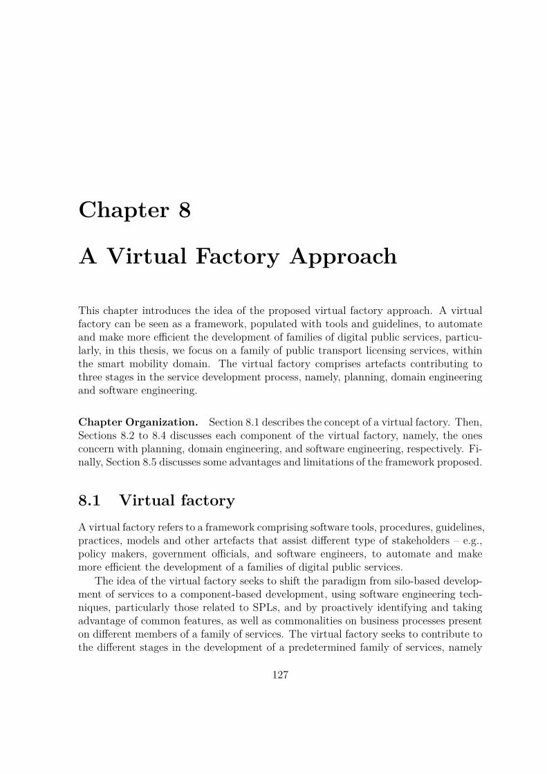
Chapter 8
A Virtual Factory Approach
This chapter introduces the idea of the proposed virtual factory approach. A virtualfactory can be seen as a framework, populated with tools and guidelines, to automateand make more efficient the development of families of digital public services, particu-larly, in this thesis, we focus on a family of public transport licensing services, withinthe smart mobility domain. The virtual factory comprises artefacts contributing tothree stages in the service development process, namely, planning, domain engineeringand software engineering.
Chapter Organization. Section 8.1 describes the concept of a virtual factory. Then,Sections 8.2 to 8.4 discusses each component of the virtual factory, namely, the onesconcern with planning, domain engineering, and software engineering, respectively. Fi-nally, Section 8.5 discusses some advantages and limitations of the framework proposed.
8.1 Virtual factoryA virtual factory refers to a framework comprising software tools, procedures, guidelines,practices, models and other artefacts that assist different type of stakeholders – e.g.,policy makers, government officials, and software engineers, to automate and makemore efficient the development of a families of digital public services.
The idea of the virtual factory seeks to shift the paradigm from silo-based develop-ment of services to a component-based development, using software engineering tech-niques, particularly those related to SPLs, and by proactively identifying and takingadvantage of common features, as well as commonalities on business processes presenton different members of a family of services. The virtual factory seeks to contribute tothe different stages in the development of a predetermined family of services, namely
127
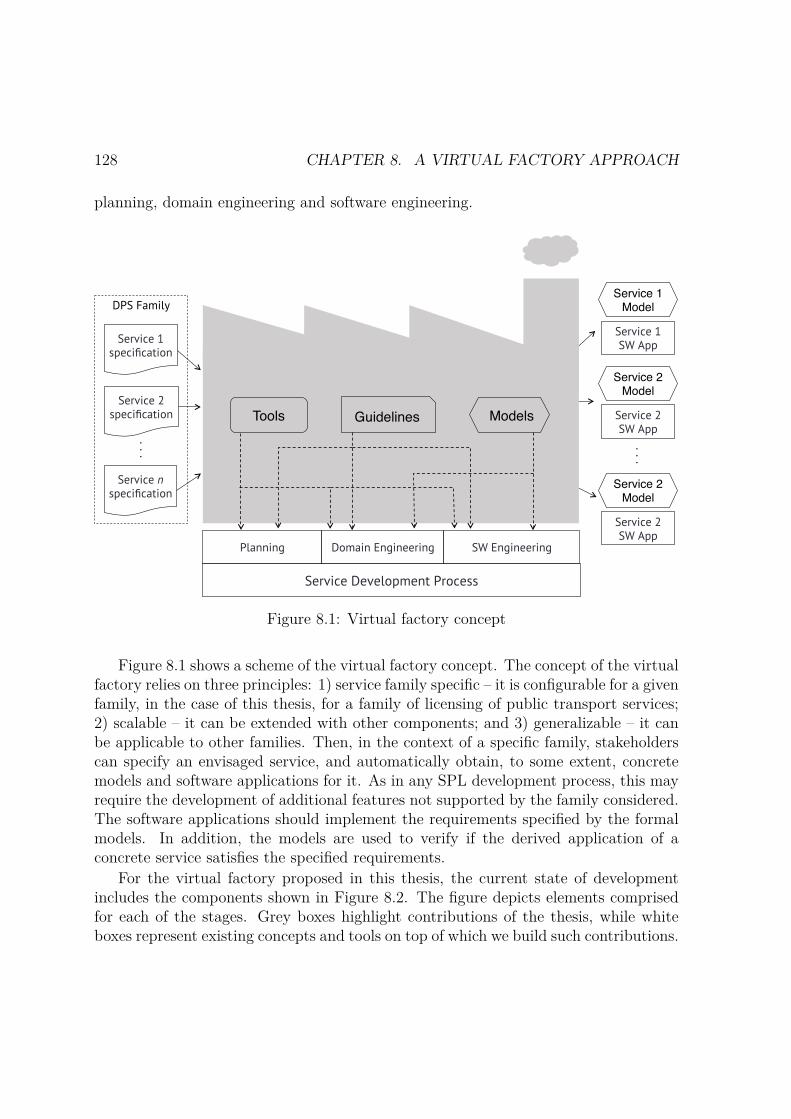
128 CHAPTER 8. A VIRTUAL FACTORY APPROACH
planning, domain engineering and software engineering.
Service 1 specification
Service 2 specification
Service n specification
. . .
DPS Family
Service 1 SW App
. . .
Service 1 Model
Service Development Process
Planning Domain Engineering SW Engineering
Tools Guidelines Models Service 2 SW App
Service 2 Model
Service 2 SW App
Service 2 Model
Figure 8.1: Virtual factory concept
Figure 8.1 shows a scheme of the virtual factory concept. The concept of the virtualfactory relies on three principles: 1) service family specific – it is configurable for a givenfamily, in the case of this thesis, for a family of licensing of public transport services;2) scalable – it can be extended with other components; and 3) generalizable – it canbe applicable to other families. Then, in the context of a specific family, stakeholderscan specify an envisaged service, and automatically obtain, to some extent, concretemodels and software applications for it. As in any SPL development process, this mayrequire the development of additional features not supported by the family considered.The software applications should implement the requirements specified by the formalmodels. In addition, the models are used to verify if the derived application of aconcrete service satisfies the specified requirements.
For the virtual factory proposed in this thesis, the current state of developmentincludes the components shown in Figure 8.2. The figure depicts elements comprisedfor each of the stages. Grey boxes highlight contributions of the thesis, while whiteboxes represent existing concepts and tools on top of which we build such contributions.
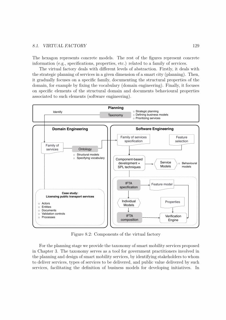
8.1. VIRTUAL FACTORY 129
The hexagon represents concrete models. The rest of the figures represent concreteinformation (e.g., specifications, properties, etc.) related to a family of services.
The virtual factory deals with different levels of abstraction. Firstly, it deals withthe strategic planning of services in a given dimension of a smart city (planning). Then,it gradually focuses on a specific family, documenting the structural properties of thedomain, for example by fixing the vocabulary (domain engineering). Finally, it focuseson specific elements of the structural domain and documents behavioural propertiesassociated to such elements (software engineering).
Software EngineeringDomain Engineering
Case study:Licensing public transport services
o Actorso Entitieso Documentso Validation controlso Processes
o Structural modelso Specifying vocabulary
Planning
Taxonomyo Strategic planningo Defining business modelso Prioritizing services
Ontology
Identify
Component-based development + SPL techniques
IFTA specification
IFTA composition
Verification Engine
o Behavioural models
Family of services
Family of services specification
Feature selection
Service Models
Feature model
Individual Models
Properties
Figure 8.2: Components of the virtual factory
For the planning stage we provide the taxonomy of smart mobility services proposedin Chapter 3. The taxonomy serves as a tool for government practitioners involved inthe planning and design of smart mobility services, by identifying stakeholders to whomto deliver services, types of services to be delivered, and public value delivered by suchservices, facilitating the definition of business models for developing initiatives. In
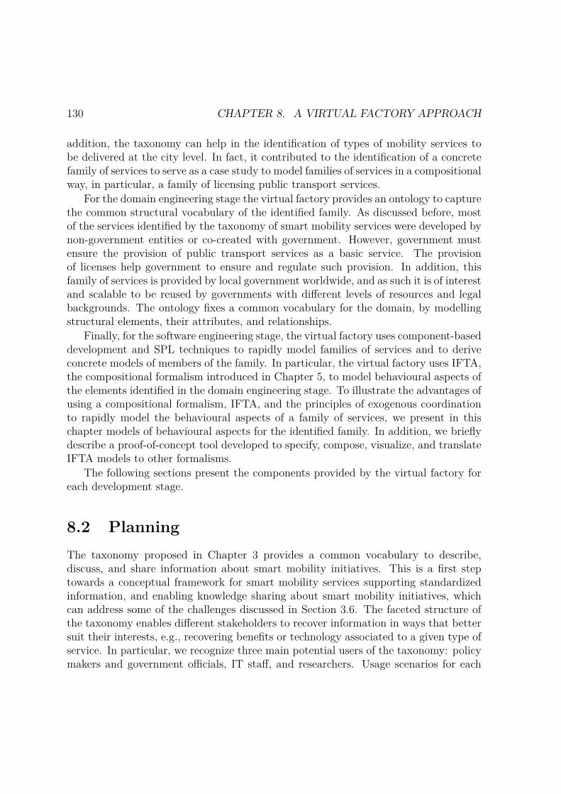
130 CHAPTER 8. A VIRTUAL FACTORY APPROACH
addition, the taxonomy can help in the identification of types of mobility services tobe delivered at the city level. In fact, it contributed to the identification of a concretefamily of services to serve as a case study to model families of services in a compositionalway, in particular, a family of licensing public transport services.
For the domain engineering stage the virtual factory provides an ontology to capturethe common structural vocabulary of the identified family. As discussed before, mostof the services identified by the taxonomy of smart mobility services were developed bynon-government entities or co-created with government. However, government mustensure the provision of public transport services as a basic service. The provisionof licenses help government to ensure and regulate such provision. In addition, thisfamily of services is provided by local government worldwide, and as such it is of interestand scalable to be reused by governments with different levels of resources and legalbackgrounds. The ontology fixes a common vocabulary for the domain, by modellingstructural elements, their attributes, and relationships.
Finally, for the software engineering stage, the virtual factory uses component-baseddevelopment and SPL techniques to rapidly model families of services and to deriveconcrete models of members of the family. In particular, the virtual factory uses IFTA,the compositional formalism introduced in Chapter 5, to model behavioural aspects ofthe elements identified in the domain engineering stage. To illustrate the advantages ofusing a compositional formalism, IFTA, and the principles of exogenous coordinationto rapidly model the behavioural aspects of a family of services, we present in thischapter models of behavioural aspects for the identified family. In addition, we brieflydescribe a proof-of-concept tool developed to specify, compose, visualize, and translateIFTA models to other formalisms.
The following sections present the components provided by the virtual factory foreach development stage.
8.2 PlanningThe taxonomy proposed in Chapter 3 provides a common vocabulary to describe,discuss, and share information about smart mobility initiatives. This is a first steptowards a conceptual framework for smart mobility services supporting standardizedinformation, and enabling knowledge sharing about smart mobility initiatives, whichcan address some of the challenges discussed in Section 3.6. The faceted structure ofthe taxonomy enables different stakeholders to recover information in ways that bettersuit their interests, e.g., recovering benefits or technology associated to a given type ofservice. In particular, we recognize three main potential users of the taxonomy: policymakers and government officials, IT staff, and researchers. Usage scenarios for each
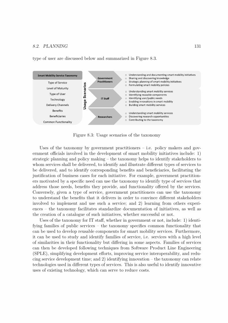
8.2. PLANNING 131
type of user are discussed below and summarized in Figure 8.3.
Figure 8.3: Usage scenarios of the taxonomy
Uses of the taxonomy by government practitioners – i.e. policy makers and gov-ernment officials involved in the development of smart mobility initiatives include: 1)strategic planning and policy making – the taxonomy helps to identify stakeholders towhom services shall be delivered, to identify and illustrate different types of services tobe delivered, and to identify corresponding benefits and beneficiaries, facilitating thejustification of business cases for each initiative. For example, government practition-ers motivated by a specific need can use the taxonomy to identify type of services thataddress those needs, benefits they provide, and functionality offered by the services.Conversely, given a type of service, government practitioners can use the taxonomyto understand the benefits that it delivers in order to convince different stakeholdersinvolved to implement and use such a service; and 2) learning from others experi-ences – the taxonomy facilitates standardize documentation of initiatives, as well asthe creation of a catalogue of such initiatives, whether successful or not.
Uses of the taxonomy for IT staff, whether in government or not, include: 1) identi-fying families of public services – the taxonomy specifies common functionality thatcan be used to develop reusable components for smart mobility services. Furthermore,it can be used to study and identify families of service, i.e. services with a high levelof similarities in their functionality but differing in some aspects. Families of servicescan then be developed following techniques from Software Product Line Engineering(SPLE), simplifying development efforts, improving service interoperability, and redu-cing service development time; and 2) identifying innovation – the taxonomy can relatetechnologies used in different types of services. This is also useful to identify innovativeuses of existing technology, which can serve to reduce costs.

132 CHAPTER 8. A VIRTUAL FACTORY APPROACH
Uses of the taxonomy by researchers include: 1) understanding the domain – thetaxonomy provides a thorough view of different aspects of smart mobility services; and2) development of new research lines – researches can use the taxonomy for discoveringresearch opportunities, e.g., by identifying new dimensions or by evolving existingdimensions based on new technology trends and innovations.
Taking full advantage of the benefits discussed above requires an online knowledgebase of smart mobility initiatives, with customizable searching tools, where each ini-tiative is described using the dimensions and concepts proposed. In practice, it ischallenging to achieve a unique global repository of initiatives. However, having ataxonomy that standardizes the domain, encourages various interested actors, mainlygovernments, in providing their own repositories. Thus, although information is notavailable in a unique place, it is consistent and structured, and facilitates (automatic)retrieval of information. In this sense, governments are considered the most interestedstakeholders responsible for providing such online platforms.
8.3 Domain EngineeringWe identified a family of licensing public transport services to pre-define and to serveas a case study for validation. As discussed in Chapter 1, this kind of services arepresent in most local governments and are required to regulate the provision of manypublic transport services.
The services in the family share common vocabulary and functionality and areamendable to be delivered through similar business processes. The domain engineeringcomponents of the virtual factory aim at fixing the general vocabulary, attributes,properties, and architectural schemes of such a domain.
In order to do this we include an ontology as one of the components for this stage.To develop the ontology, first, we selected two countries, Ireland and Portugal, to studyservices of licensing public bus passenger services, and we analysed how the serviceswere delivered in both cases. We analysed government guidelines and applicationforms from both countries with the purpose of identifying: 1) licenses required for theprovision of public bus transport services, 2) documentation required for the applicationof each license, 3) application process activities, and 4) entities involved in the provisionof the licensing services.
Based on the analysis, we propose an ontology of public bus passenger services tocapture the common vocabulary of the domain and to standardize knowledge. Theproposed ontology captures common concepts – e.g. actors, supporting documents,and attributes required in the application and processing stage of three licenses: 1) alicense to operate passenger services, 2) a license to provide a bus passenger service
8.3. DOMAIN ENGINEERING 133
across specified pick up and set down points following a predefined schedule and a farescheme, and 3) a license for each vehicle used to transport passengers.
In the following subsections we describe the methodology used to build the ontologyand the ontology itself.
8.3.1 MethodologyThe research methodology comprises four activities explained below and it is illustratedin Figure 8.4.
– Literature Review – 1) assessing existing related work on the development ofdigital licensing services, and on the use of ontologies to support Digital Govern-ment, 2) identifying a family of licensing public transport services to serve as casestudy, sharing common vocabulary and functionality amendable to be deliveredthrough similar business processes.
– Domain Analysis – to understand the licensing public transport service domain,in particular by studying government guidelines and application forms from twocase studies of licensing public bus passenger services. The domain analysisproduced UML Class and Activity Diagrams, contributing to identifying maindomain elements and business processes used during the licensing applicationand processing stages.
– Ontology Analysis – studying methodologies and tools used to define ontologiesand selecting a suitable approach to define an ontology for licensing public trans-port services. The background study on ontologies was described in [40].
– Ontology Definition – defining an ontology for licensing public transport servicesable to capture common vocabulary of the various services in the family analysedin the domain analysis, and using methodologies and tools selected from theontology analysis activity.
8.3.2 OntologyThis section describes each of the steps applied to build the ontology of public transportlicensing services.
We follow the Representation Formalism for Software Engineering Ontologies (REF-SENO) methodology [142]. It is a representation formalism to model the structure ofan experience base for software engineering. The motivation behind this formalism isto build ontologies to: collect experiences from software projects; capture and reuse
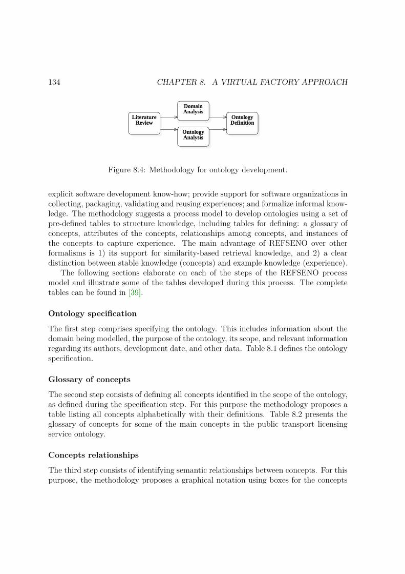
134 CHAPTER 8. A VIRTUAL FACTORY APPROACH
Figure 8.4: Methodology for ontology development.
explicit software development know-how; provide support for software organizations incollecting, packaging, validating and reusing experiences; and formalize informal know-ledge. The methodology suggests a process model to develop ontologies using a set ofpre-defined tables to structure knowledge, including tables for defining: a glossary ofconcepts, attributes of the concepts, relationships among concepts, and instances ofthe concepts to capture experience. The main advantage of REFSENO over otherformalisms is 1) its support for similarity-based retrieval knowledge, and 2) a cleardistinction between stable knowledge (concepts) and example knowledge (experience).
The following sections elaborate on each of the steps of the REFSENO processmodel and illustrate some of the tables developed during this process. The completetables can be found in [39].
Ontology specification
The first step comprises specifying the ontology. This includes information about thedomain being modelled, the purpose of the ontology, its scope, and relevant informationregarding its authors, development date, and other data. Table 8.1 defines the ontologyspecification.
Glossary of concepts
The second step consists of defining all concepts identified in the scope of the ontology,as defined during the specification step. For this purpose the methodology proposes atable listing all concepts alphabetically with their definitions. Table 8.2 presents theglossary of concepts for some of the main concepts in the public transport licensingservice ontology.
Concepts relationships
The third step consists of identifying semantic relationships between concepts. For thispurpose, the methodology proposes a graphical notation using boxes for the concepts
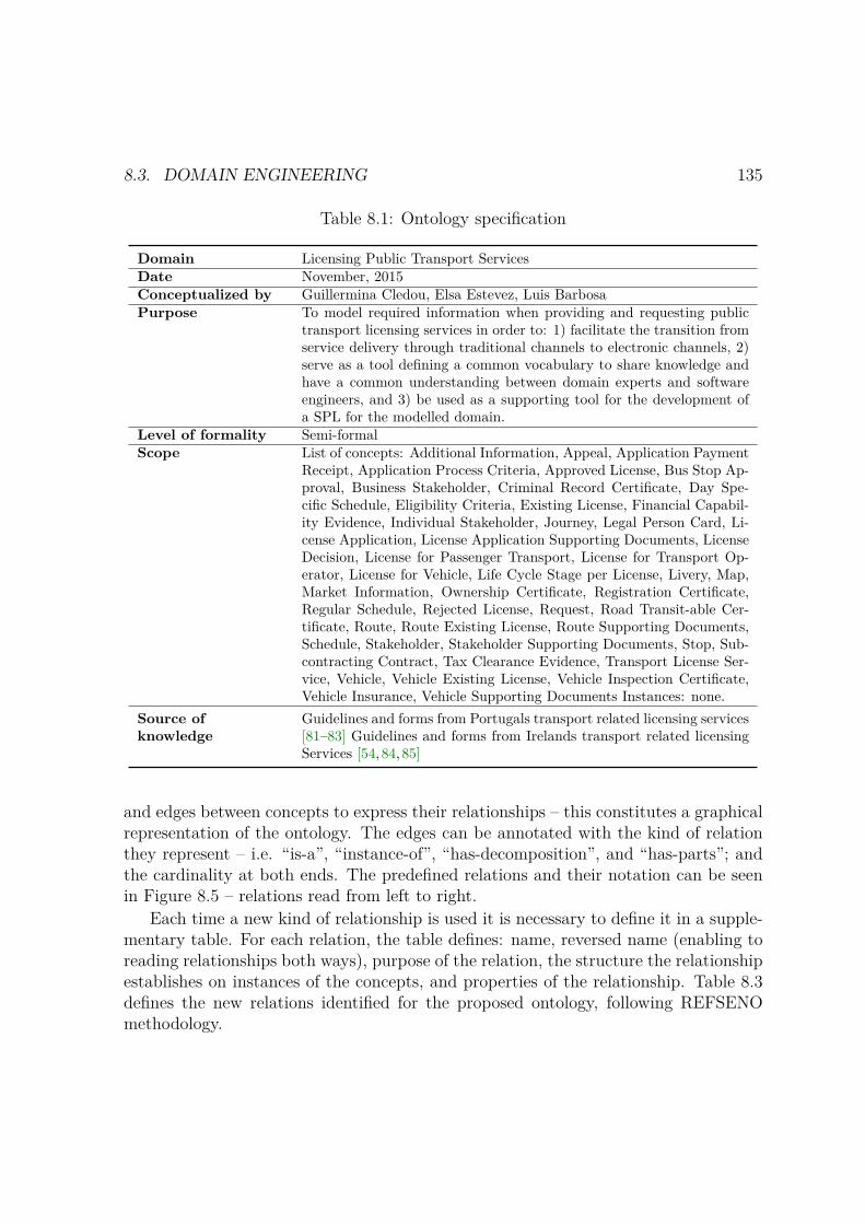
8.3. DOMAIN ENGINEERING 135
Table 8.1: Ontology specification
Domain Licensing Public Transport ServicesDate November, 2015Conceptualized by Guillermina Cledou, Elsa Estevez, Luis BarbosaPurpose To model required information when providing and requesting public
transport licensing services in order to: 1) facilitate the transition fromservice delivery through traditional channels to electronic channels, 2)serve as a tool defining a common vocabulary to share knowledge andhave a common understanding between domain experts and softwareengineers, and 3) be used as a supporting tool for the development ofa SPL for the modelled domain.
Level of formality Semi-formalScope List of concepts: Additional Information, Appeal, Application Payment
Receipt, Application Process Criteria, Approved License, Bus Stop Ap-proval, Business Stakeholder, Criminal Record Certificate, Day Spe-cific Schedule, Eligibility Criteria, Existing License, Financial Capabil-ity Evidence, Individual Stakeholder, Journey, Legal Person Card, Li-cense Application, License Application Supporting Documents, LicenseDecision, License for Passenger Transport, License for Transport Op-erator, License for Vehicle, Life Cycle Stage per License, Livery, Map,Market Information, Ownership Certificate, Registration Certificate,Regular Schedule, Rejected License, Request, Road Transit-able Cer-tificate, Route, Route Existing License, Route Supporting Documents,Schedule, Stakeholder, Stakeholder Supporting Documents, Stop, Sub-contracting Contract, Tax Clearance Evidence, Transport License Ser-vice, Vehicle, Vehicle Existing License, Vehicle Inspection Certificate,Vehicle Insurance, Vehicle Supporting Documents Instances: none.
Source ofknowledge
Guidelines and forms from Portugals transport related licensing services[81–83] Guidelines and forms from Irelands transport related licensingServices [54,84,85]
and edges between concepts to express their relationships – this constitutes a graphicalrepresentation of the ontology. The edges can be annotated with the kind of relationthey represent – i.e. “is-a”, “instance-of”, “has-decomposition”, and “has-parts”; andthe cardinality at both ends. The predefined relations and their notation can be seenin Figure 8.5 – relations read from left to right.
Each time a new kind of relationship is used it is necessary to define it in a supple-mentary table. For each relation, the table defines: name, reversed name (enabling toreading relationships both ways), purpose of the relation, the structure the relationshipestablishes on instances of the concepts, and properties of the relationship. Table 8.3defines the new relations identified for the proposed ontology, following REFSENOmethodology.
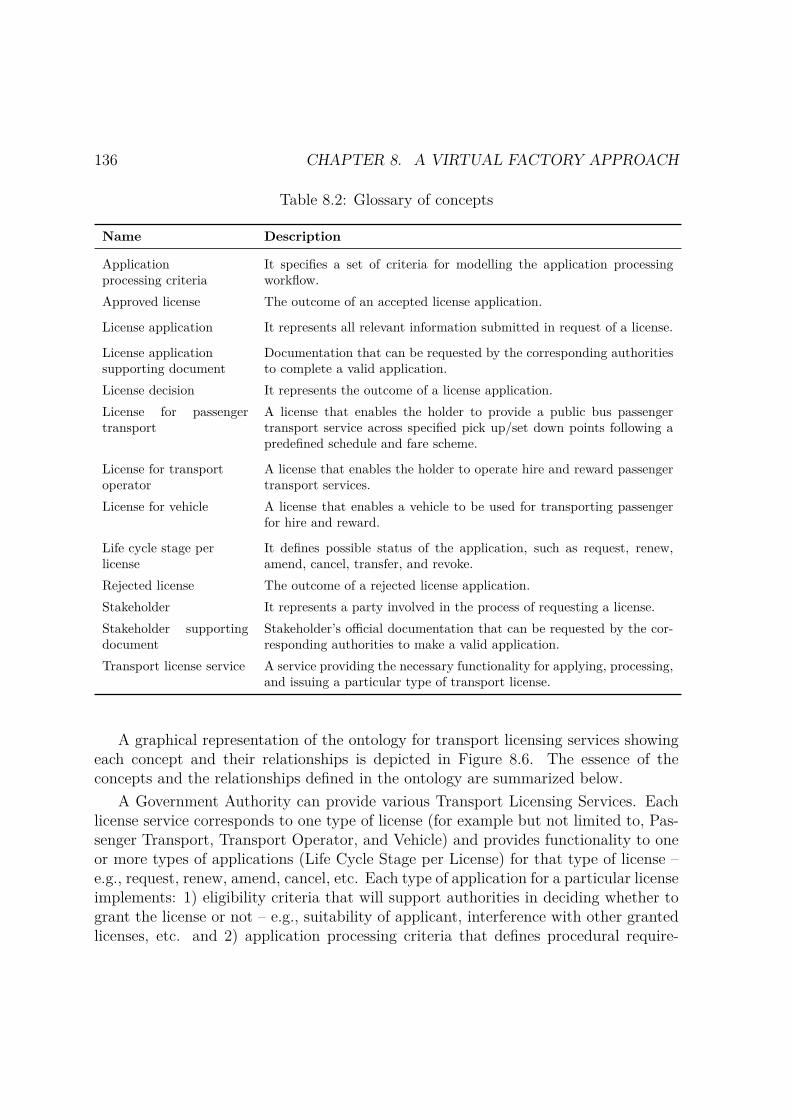
136 CHAPTER 8. A VIRTUAL FACTORY APPROACH
Table 8.2: Glossary of concepts
Name Description
Applicationprocessing criteria
It specifies a set of criteria for modelling the application processingworkflow.
Approved license The outcome of an accepted license application.
License application It represents all relevant information submitted in request of a license.
License applicationsupporting document
Documentation that can be requested by the corresponding authoritiesto complete a valid application.
License decision It represents the outcome of a license application.License for passengertransport
A license that enables the holder to provide a public bus passengertransport service across specified pick up/set down points following apredefined schedule and fare scheme.
License for transportoperator
A license that enables the holder to operate hire and reward passengertransport services.
License for vehicle A license that enables a vehicle to be used for transporting passengerfor hire and reward.
Life cycle stage perlicense
It defines possible status of the application, such as request, renew,amend, cancel, transfer, and revoke.
Rejected license The outcome of a rejected license application.Stakeholder It represents a party involved in the process of requesting a license.Stakeholder supportingdocument
Stakeholder’s official documentation that can be requested by the cor-responding authorities to make a valid application.
Transport license service A service providing the necessary functionality for applying, processing,and issuing a particular type of transport license.
A graphical representation of the ontology for transport licensing services showingeach concept and their relationships is depicted in Figure 8.6. The essence of theconcepts and the relationships defined in the ontology are summarized below.
A Government Authority can provide various Transport Licensing Services. Eachlicense service corresponds to one type of license (for example but not limited to, Pas-senger Transport, Transport Operator, and Vehicle) and provides functionality to oneor more types of applications (Life Cycle Stage per License) for that type of license –e.g., request, renew, amend, cancel, etc. Each type of application for a particular licenseimplements: 1) eligibility criteria that will support authorities in deciding whether togrant the license or not – e.g., suitability of applicant, interference with other grantedlicenses, etc. and 2) application processing criteria that defines procedural require-

8.3. DOMAIN ENGINEERING 137
Figure 8.5: Predefine relation types
Figure 8.6: Transport licensing services ontology
ments for authorities when processing the applications and procedural requirementsfor applicants when submitting applications – e.g., deadlines for processing applica-tions, whether resubmission of incomplete applications are allowed, if a fee is required,etc.
Each License Application involves various stakeholders, either individuals or busi-nesses, such as the applicant (mandatory), members of the business in the case theapplicant is a business, and subcontractors if the applicant intends to subcontractpart of the future license obligations to other stakeholder. A license application mayrequire various supporting documents for each stakeholder. The type of documentsrequired will vary on the type of license, the type of the application and the actualimplementation of the licensing services. In the proposed ontology, we define typicaldocuments requested from stakeholders that were identified from the case studies: legal
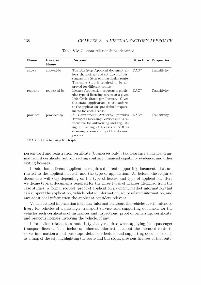
138 CHAPTER 8. A VIRTUAL FACTORY APPROACH
Table 8.3: Custom relationships identified
Name ReverseName
Purpose Structure Properties
allows allowed-by The Bus Stop Approval document al-lows the pick up and set down of pas-sengers in a Stop of a particular route.The same Stop is required to be ap-proved for different routes.
DAG* Transitivity
requests requested-by License Application requests a partic-ular type of licensing service at a givenLife Cycle Stage per License. Giventhe state, applications must conformto the applications pre-defined require-ments for each license.
DAG* Transitivity
provides provided-by A Government Authority providesTransport Licensing Services and is re-sponsible for authorizing and regulat-ing the issuing of licenses as well asensuring accountability of the decisionprocess.
DAG* Transitivity
*DAG = Directed Acyclic Graph
person card and registration certificate (businesses only), tax clearance evidence, crim-inal record certificate, subcontracting contract, financial capability evidence, and otherexiting licenses.
In addition, a license application requires different supporting documents that arerelated to the application itself and the type of application. As before, the requireddocuments will vary depending on the type of license and type of application. Herewe define typical documents required for the three types of licenses identified from thecase studies: a formal request, proof of application payment, market information thatcan support the application, vehicle related information, route related information, andany additional information the applicant considers relevant.
Vehicle related information includes: information about the vehicles it self, intendedlivery for vehicles of a passenger transport service, and supporting document for thevehicles such certificates of insurances and inspections, proof of ownership, certificate,and previous licenses involving the vehicle, if any.
Information related to a route is typically required when applying for a passengertransport license. This includes: inherent information about the intended route toserve, information about bus stops, detailed schedule, and supporting documents suchas a map of the city highlighting the route and bus stops, previous licenses of the route,

8.3. DOMAIN ENGINEERING 139
a certificate to attest that the route is transitable, and certificates of approval to pickup and set down passengers in each of the intended bus stops for the route.
Finally, a license application will result in a decision whether to accept or to rejectthe issuing of the license. In case the license application is rejected, the applicant mayhave the right to appeal such decision.
Concept attribute table
The fourth and fifth steps in the process model consist of identifying and definingterminal and non-terminal attributes for each of the concepts defined in the ontology.The methodology proposes a pre-defined table to capture such knowledge. The tableis divided in two sections – concept related information, and attributes information.The former specifies the concept and its super-concept, if any. It is assumed thatthe concept inherits attributes from its super-concept. The latter specifies attributeinformation such as name, description, cardinality, type and whether it is mandatoryor not. Both terminal and non-terminal attributes are defined in the concept table.However, for reasons of clarity and to respect the order in which the activities of eachstep are performed we present them here using two separate tables. We introducethese activities and present some results from the proposed ontology below. Attributesfor each concept were extracted from guidelines and application forms from both casestudies.
A terminal concept attribute serves to model how software engineering entities arespecified for storage and retrieval. It can be seen as a property or a data element ofa concept. Table 8.4illustrates various concept attributes tables for some of the mainconcepts identified in the ontology.
Table 8.4: Concept attribute table – terminal attributes
Concept Transport License ServiceSuper-Concept -
Name Description Card Type Mand.
license id Identification code for the license 1 Text Yeslicense name Name of the license 1 Text Yes
Concept License Cycle Stage per LicenseSuper-Concept -
Name Description Card Type Mand.
license duration Time during which the license is granted 1 Integer Yeslicense durationunit
Unit of measure for the duration of the license 1 Date Unit No
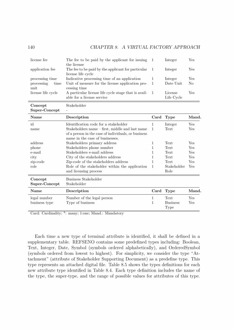
140 CHAPTER 8. A VIRTUAL FACTORY APPROACH
license fee The fee to be paid by the applicant for issuingthe license
1 Integer Yes
application fee The fee to be paid by the applicant for particularlicense life cycle
1 Integer Yes
processing time Indicative processing time of an application 1 Integer Yesprocessing timeunit
Unit of measure for the license application pro-cessing time
1 Date Unit No
license life cycle A particular license life cycle stage that is avail-able for a license service
1 LicenseLife Cycle
Yes
Concept StakeholderSuper-Concept -
Name Description Card Type Mand.
id Identification code for a stakeholder 1 Integer Yesname Stakeholders name – first, middle and last name
of a person in the case of individuals, or businessname in the case of businesses.
1 Text Yes
address Stakeholders primary address 1 Text Yesphone Stakeholders phone number 1 Text Yese-mail Stakeholders e-mail address 1 Text Yescity City of the stakeholders address 1 Text Yeszip-code Zip-code of the stakeholders address 1 Text Yesrole Role of the stakeholder within the application
and licensing process1 Stakeholder
RoleYes
Concept Business StakeholderSuper-Concept Stakeholder
Name Description Card Type Mand.
legal number Number of the legal person 1 Text Yesbusiness type Type of business 1 Business
TypeYes
Card: Cardinality; *: many; 1:one; Mand.: Mandatory
Each time a new type of terminal attribute is identified, it shall be defined in asupplementary table. REFSENO contains some predefined types including: Boolean,Text, Integer, Date, Symbol (symbols ordered alphabetically), and OrderedSymbol(symbols ordered from lowest to highest). For simplicity, we consider the type “At-tachment” (attribute of Stakeholder Supporting Document) as a predefine type. Thistype represents an attached digital file. Table 8.5 shows the types definitions for eachnew attribute type identified in Table 8.4. Each type definition includes the name ofthe type, the super-type, and the range of possible values for attributes of this type.

8.3. DOMAIN ENGINEERING 141
The legend DYNAMIC following the range definition informs that the range of possiblevalues can be extended.
If the types table includes declarations of symbol types it is necessary to define aglossary of symbols including a narrative definition for each possible value. Table 8.6shows the symbol definition for some of the symbols types identified.
Table 8.5: Types
Name Super-Type Value Range
Date Unit OrderedSymbol “Day”, “Week”, “Month”, “Year”License Life Cycle OrderedSymbol “Request”, “Renewal”, “Transference”, “Amend-
ment”, “Cancelation”, “Revocation”Application Life Cycle OrderedSymbol “Submitted”, “Processing”, “Rejected”, “Accep-
ted” DYNAMICPayment Method Symbol “Card”, “Cash”, “Cheque”, “Postal Order”, DY-
NAMICStakeholder Role Symbol “Applicant”, “Business Member”, “Subcon-
tractor”, DYNAMICBusiness Type Symbol “Company”,“Cooperative”, “Partnership” “Sole
Trader”, DYNAMIC
Similarly, we identify non-terminal attributes. A non-terminal attribute modelshow a particular software engineering entity is related to other software engineeringentities. It can be seen as an association to other non-terminal concept. Non-terminalattributes of the predefined kind “is-a” are not represented explicitly in the table sincesuch relationship is represented through the declaration of the super-concept. Followingthe table structure introduced in the previous section, Table 8.7 illustrates the conceptattribute tables with non-terminal attributes for the concepts defined in Table 8.4.
Table 8.7: Concept attribute table – non-terminal attributes
Concept Transport License ServiceSuper-Concept -
Name Description Card Type Mand.
life cycle Stages in the license life cycle thatthe license service supports andprovides functionality for
* has-parts[Life CycleStage per Li-cense].[license service]* Yes
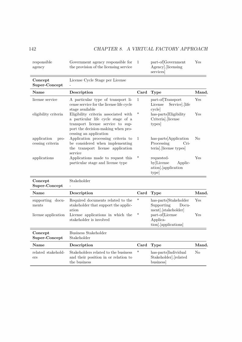
142 CHAPTER 8. A VIRTUAL FACTORY APPROACH
responsibleagency
Government agency responsible forthe provision of the licensing service
1 part-of[GovernmentAgency].[licensingservices]
Yes
Concept License Cycle Stage per LicenseSuper-Concept -
Name Description Card Type Mand.
license service A particular type of transport li-cense service for the license life cyclestage available
1 part-of[TransportLicense Service].[lifecycle]
Yes
eligibility criteria Eligibility criteria associated witha particular life cycle stage of atransport license service to sup-port the decision-making when pro-cessing an application
* has-parts[EligibilityCriteria].[licensetypes]
Yes
application pro-cessing criteria
Application processing criteria tobe considered when implementingthe transport license applicationservice
1 has-parts[ApplicationProcessing Cri-teria].[license types]
No
applications Applications made to request thisparticular stage and license type
* requested-by[License Applic-ation].[applicationtype]
Yes
Concept StakeholderSuper-Concept -
Name Description Card Type Mand.
supporting docu-ments
Required documents related to thestakeholder that support the applic-ation
* has-parts[StakeholderSupporting Docu-ment].[stakeholder]
Yes
license application License applications in which thestakeholder is involved
* part-of[LicenseApplica-tion].[applications]
Yes
Concept Business StakeholderSuper-Concept Stakeholder
Name Description Card Type Mand.
related stakehold-ers
Stakeholders related to the businessand their position in or relation tothe business
* has-parts[IndividualStakeholder].[relatedbusiness]
No

8.3. DOMAIN ENGINEERING 143
Table 8.6: Glossary of symbols
Name Super-Type Value Range
License Life Cycle Request Request for a new licenseRenewal Request to renew an existing licenseTransference Request to transfer an existing license from one indi-
vidual or business to anotherAmendment Request to make changes to some of the terms and con-
ditions of an existing licenseCancellation Request to cancel the validity of an existing licenseRevocation Request to withdraw an existing valid license
Stakeholder Role Business Member A person that is member of or related to a businessstakeholder
Subcontractor A stakeholder that posses a required license and is sub-contracted to perform the obligations related to the li-cense
Applicant A stakeholder that is the main responsible for the ap-plication process and the beneficiary of the license ifgranted
Completeness check
The sixth step in the process model involves checking the completeness of all conceptattribute tables. As defined in Table 8.1, the purpose of the proposed ontology is toprovide common vocabulary for the modelled domain with the intention of facilitatingthe generation of families of transport licensing services. This implies that the ontologywill potentially be used to instantiate licensing public bus passenger services in verydifferent environments – different countries with different laws and regulations. There-fore, the approach is only to define most elemental attributes for each concept. Eachinstantiation of the ontology can later define additional attributes and even additionalconcepts. Thus, completeness check is performed considering only elemental attributesthat will likely be present in every instantiation of the concept. Based on this, eachconcept attribute table is complete with respect to the small set of such attributes.
Instantiation
The final step in building an ontology using REFSENO involves defining the instancesspecified in the ontology definition table (Table 8.1). For each instance, the methodo-logy proposes a table containing an instance identification name, the concept associatedto the instance, and the values for each of the attributes defined in the concept attribute
144 CHAPTER 8. A VIRTUAL FACTORY APPROACH
table. However, this goes out of the scope of the intended use.
8.3.3 DiscussionAn advantage of building ontologies with REFSENO is that by construction it ensures:1) completeness in the sense that all relevant knowledge to instantiate a knowledgebase is defined; and 2) consistency in the sense that some consistency criteria haveto be fulfilled during the construction such as: a) no concept, types, instances orattributes of a same concept have the same name, b) graphical representation of thenon-terminal attributes and their relationships must match the tabular representation,etc. In addition, the table structure used to defined the ontology is easy to understandby domain experts.
The main aim of the proposed ontology is to facilitate the definition of genericmodels to support the definition of a family of software applications for licensing publictransport services adopting SPL engineering methods and tools. However, by defin-ing a common vocabulary, the ontology can serve other purposes: 1) facilitating thetransition from paper-based delivery channels to electronic ones; 2) facilitating the in-tegration of different licensing systems, and 3) improving government interoperability.The last two are important because they facilitate information sharing between agen-cies enabling the delivery of one-stop, seamless services, and the implementation of the“only-once” principle for reducing administrative burden [66].
As a limitation of the ontology, we highlight that the ontology itself does not definewhich supporting documents correspond to which type of license application.
8.4 Software EngineeringThe software engineering component deals with the rapid modelling of digital publicservices in a given family and the automatic generation of software applications thatsupport the delivery of such services, implementing the requirements specified by themodels. In particular, it relies on component-based and software product line tech-niques. The current components of the virtual factory supporting this stage focus onthe rapid modelling of behavioural aspects of a family of services, and comprise thefollowing elements:
a) A specification language for service modelling and assembly by feature composi-tion;
b) A proof-of-concept prototype to specify, compose, visualize, and translate therelevant models to other well-known formalisms;
8.4. SOFTWARE ENGINEERING 145
c) A verification engine to check whether properties documenting the family aresatisfied by the models.
In particular, the formalism used to define the behavioural models is IFTA asintroduced in Chapter 5; while for the verification engine c) we use of-the-shelf tools,particularly the Uppaal real time model checker, to which we translate IFTA modelsto verify temporal properties of the services in the family.
To populate the virtual factory and to illustrate its usage, we model some behavi-oural aspects of the identified family, providing in particular:
– A feature model specifying domain variability in terms of common and optionalfunctionality present in the services of the selected family
– Behavioural models characterising features representing functionality of the do-main and Temporal properties of such models
8.4.1 Case StudyThis section presents the behavioural characteristics identified from the analysis ofthe family of services studied. In particular, we use IFTA to formally specify thebehaviour. It is worth to mention that in both cases, Ireland and Portugal, the licensingservices were being delivered by paper-based solutions. In this sense, some functionalitydescribed here, such as the support for online payments, was not present in the originalcase studies.
Feature model
We propose a feature model, illustrated in Figure 8.7, to express the valid combina-tion of features present in the family of licensing public transport services. It followsdirectly from the identification of the structural (Section 8.3) and behavioural aspects(Section 8.4.1) of the case study.
The root feature represents the family of licenses. The top sub-features – license,documents, and license life cycle correspond to features identified from the structuralanalysis of the case study and coming from the respective elements of the ontology.Intuitively, only one type of license can be derived at a time (alternative features):transport operator, passenger transport, or passenger vehicle. Each license must have,at least (mandatory features), documents associated to the stakeholder and the applic-ation. The specific documents depend on each particular context (optional features),i.e. specific local government. A license service must support at least the request of anew license, but it can optionally provide functionality to support other requests in the

146 CHAPTER 8. A VIRTUAL FACTORY APPROACH
license life cycle. The last sub-feature of the root represents the support for businessprocesses identified from the case study. All licenses provide support for three mainprocess – submission of the application, processing of the application, and issuing of thelicense. In addition, some submissions require payments, which can support paymentsby credit card or by PayPal; and resubmitting documents in case some documents aremissing. In addition, some licenses can support an appeal on a rejected license.
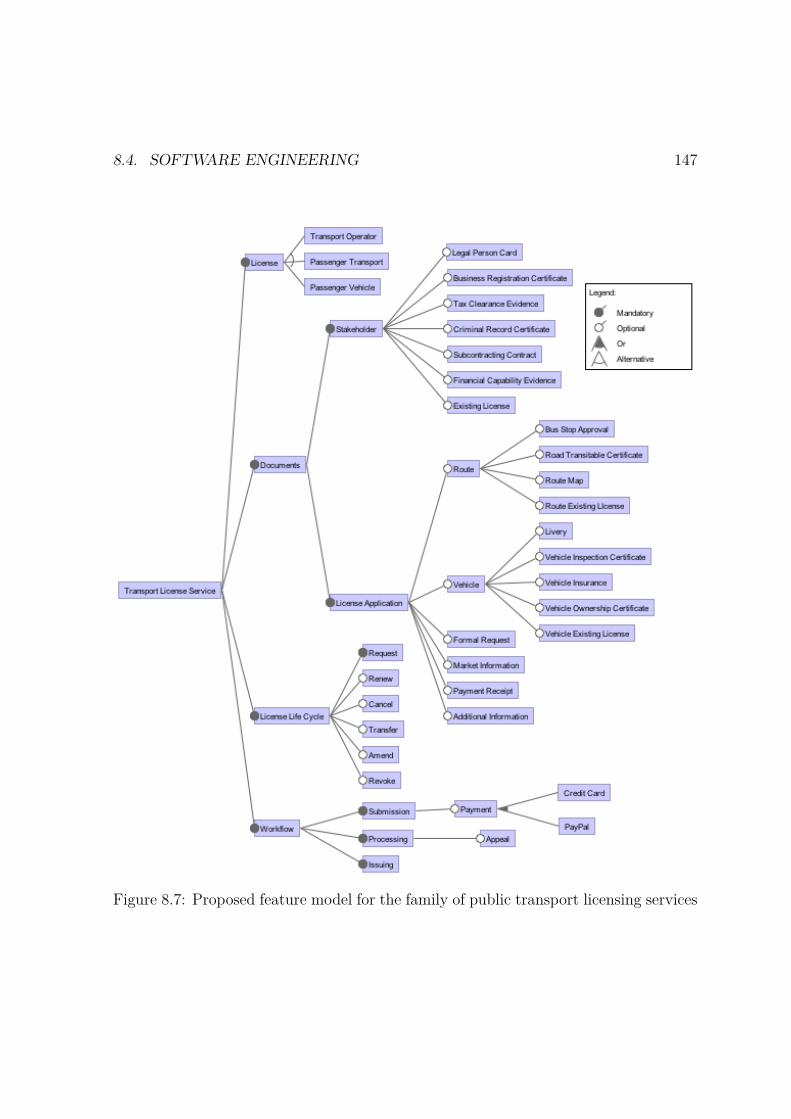
8.4. SOFTWARE ENGINEERING 147
Figure 8.7: Proposed feature model for the family of public transport licensing services
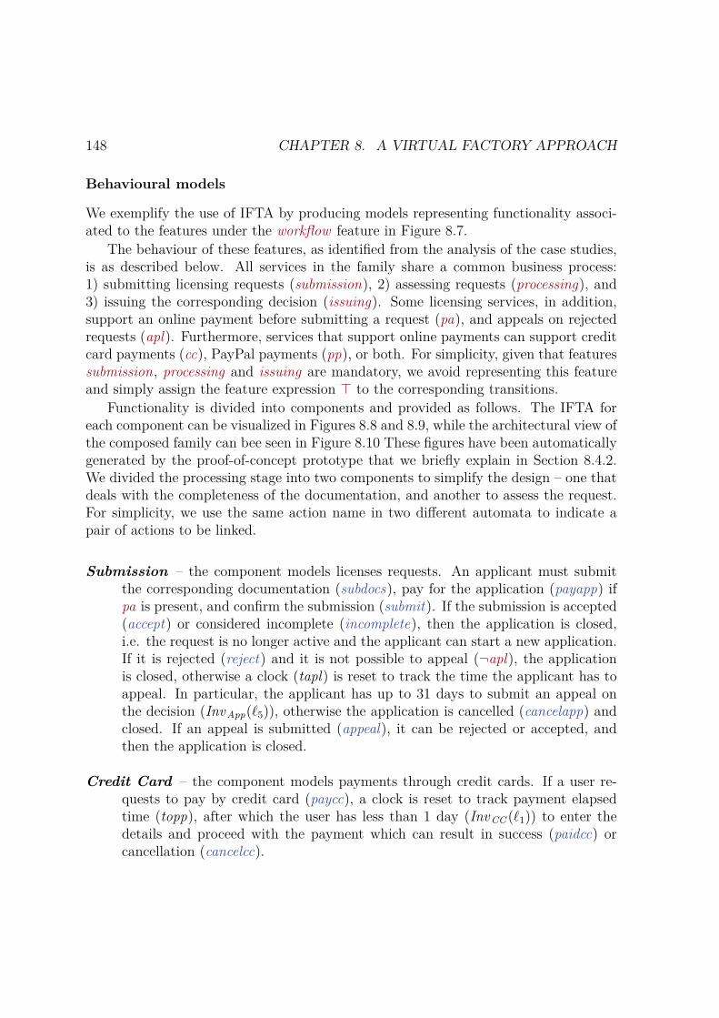
148 CHAPTER 8. A VIRTUAL FACTORY APPROACH
Behavioural models
We exemplify the use of IFTA by producing models representing functionality associ-ated to the features under the workflow feature in Figure 8.7.
The behaviour of these features, as identified from the analysis of the case studies,is as described below. All services in the family share a common business process:1) submitting licensing requests (submission), 2) assessing requests (processing), and3) issuing the corresponding decision (issuing). Some licensing services, in addition,support an online payment before submitting a request (pa), and appeals on rejectedrequests (apl). Furthermore, services that support online payments can support creditcard payments (cc), PayPal payments (pp), or both. For simplicity, given that featuressubmission, processing and issuing are mandatory, we avoid representing this featureand simply assign the feature expression ⊤ to the corresponding transitions.
Functionality is divided into components and provided as follows. The IFTA foreach component can be visualized in Figures 8.8 and 8.9, while the architectural view ofthe composed family can bee seen in Figure 8.10 These figures have been automaticallygenerated by the proof-of-concept prototype that we briefly explain in Section 8.4.2.We divided the processing stage into two components to simplify the design – one thatdeals with the completeness of the documentation, and another to assess the request.For simplicity, we use the same action name in two different automata to indicate apair of actions to be linked.
Submission – the component models licenses requests. An applicant must submitthe corresponding documentation (subdocs), pay for the application (payapp) ifpa is present, and confirm the submission (submit). If the submission is accepted(accept) or considered incomplete (incomplete), then the application is closed,i.e. the request is no longer active and the applicant can start a new application.If it is rejected (reject) and it is not possible to appeal (¬apl), the applicationis closed, otherwise a clock (tapl) is reset to track the time the applicant has toappeal. In particular, the applicant has up to 31 days to submit an appeal onthe decision (InvApp(ℓ5)), otherwise the application is cancelled (cancelapp) andclosed. If an appeal is submitted (appeal), it can be rejected or accepted, andthen the application is closed.
Credit Card – the component models payments through credit cards. If a user re-quests to pay by credit card (paycc), a clock is reset to track payment elapsedtime (topp), after which the user has less than 1 day (InvCC (ℓ1)) to enter thedetails and proceed with the payment which can result in success (paidcc) orcancellation (cancelcc).

8.4. SOFTWARE ENGINEERING 149
(a) CreditCard (b) PayPal
(c) Appeal (d) Assessment
(e) Preassessment
Figure 8.8: IFTA models for the Preassessment, Assessment, Appeal, Credit Card, andPaypal components.
PayPal – the component models payments through Paypal accounts. If a user re-quests to pay by Paypal (paypp), a clock is reset to track payment elapsed time(tocc), after which the user has less than 1 day (InvPP(ℓ1)) to enter login andproceed with the payment which can result in success (paidpp) or cancellation(cancelpp).
Appeal – the component models the process of handling appeal requests. When anappeal on a decision (appeal) is received, a clock is reset to track the appealsubmission elapsed time (tas), after which the corresponding authority has up to20 days (InvAppeal(ℓ1)) to start assessing the request (assessapl).
Preassessment – the component models the process of checking if a request containsall required documentation. When a submission is received (submit), a clock isreset to track the submission elapsed time (ts), after which the correspondingauthority has up to 20 days (InvPreassesment(ℓ1)) to check if all required documents
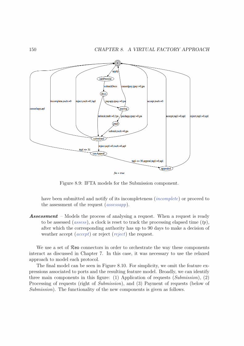
150 CHAPTER 8. A VIRTUAL FACTORY APPROACH
Figure 8.9: IFTA models for the Submission component.
have been submitted and notify of its incompleteness (incomplete) or proceed tothe assessment of the request (assessapp).
Assessment – Models the process of analysing a request. When a request is readyto be assessed (assess), a clock is reset to track the processing elapsed time (tp),after which the corresponding authority has up to 90 days to make a decision ofweather accept (accept) or reject (reject) the request.
We use a set of Reo connectors in order to orchestrate the way these componentsinteract as discussed in Chapter 7. In this case, it was necessary to use the relaxedapproach to model each protocol.
The final model can be seen in Figure 8.10. For simplicity, we omit the feature ex-pressions associated to ports and the resulting feature model. Broadly, we can identifythree main components in this figure: (1) Application of requests (Submission), (2)Processing of requests (right of Submission), and (3) Payment of requests (below ofSubmission). The functionality of the new components is given as follows.
8.4. SOFTWARE ENGINEERING 151
Figure 8.10: Architectural view of the composed family of licensing services
Payment – Models the orchestration of payment requests based on the availabilityof payment methods. It is composed by components CC, PP, a router and twomerger connectors. If a request for payment is received (payapp) a router enablesto choose between pay by Credit Card or Paypal (paypp or paycc). A mergersynchronizes the successful response (paidpp or paidcc), while other merger syn-chronizes the cancellation response (cancelpp or cancelcc) from either CC or PP.In addition to the feature model generated by the composition of these IFTA, thepayment component imposes the additional restriction that payment is suppor-ted by the system, if and only if, Credit card or Paypal payment are supported(pa ↔ cc ∨ pp).
Processing – Models the orchestration of processing licenses requests and appeals ondecisions (when apl is present). It is composed by components Appeal, Preassess,Assess, and a merger connector that synchronizes assessment request from eitherAppeal or Preassess (assessapl or assessapp) with Assess (assess).
As composition of IFTA combines the variability models of each individual auto-mata and imposes new restrictions based on the interfaces connected, the resultingmodel will adapt automatically based on the feature selection. For example, if pp is

152 CHAPTER 8. A VIRTUAL FACTORY APPROACH
not present, the router in Figure 8.10 will behave as a Sync connector, synchronizingonly actions payapp and paycc. Similarly, both merger that synchronize the outputs ofPP, will behave as a Sync that synchronizes cancelcc with cancelpay , and paidcc withpaidapp. In Section 7.2 we illustrated using a network of IFTA specifying a complexconnector how the prototype developed facilitates the visualization of these changesbased on the possible feature selections.
By specifying the previous components using the prototype described in the nextsection, we can translate them to Uppaal as a network of TA, or as an unique TAresulted from using IFTA composition, and verify properties such as:
– Deadlock free – A[] not deadlock;
– Liveness – a submition will eventually result in answer (App.ℓ4 -> App.ℓ0), anappeal will eventually result in answer (App.ℓ6 -> App.ℓ0), etc.; and
– Safety – it can not take longer than 110 days to process a submission (A[] App.ℓ4imply App.tsub <=110), it can not take longer than a day to pay a request afterthe payment was initiated (A[] App.ℓ2 imply App.tpay <=1), etc.
8.4.2 PrototypeThis section presents the proof-of-concept prototype implemented in the context ofthis thesis, and discusses some implementation decisions. Further documentation anddiscussion can be found in [37].
The prototype was developed in Scala1 and consists of a small Domain SpecificLanguage (DSL) to support specification of IFTA and networks of IFTA (NIFTA),and some operations over them. By a network of any kind of automata we understanda set of automata composed in parallel (||) and synchronized over a set of sharedactions.
Scala DSL for IFTA
Some of the main features supported by the DSL include: 1) specification of (N)IFTA,2) composition, product and synchronization over IFTA, 3) conversion of (N)IFTA to(networks of) FTA (NFTA) with committed states (CS), 4) conversion of (N)IFTA andNFTA to DOT2 graph description language, 5) conversion of (N)IFTA to an interactive.html file using the Vis.js3 visualization library, and 6) conversion of NFTA to Uppaal
1https://github.com/haslab/ifta2http://www.graphviz.org/about/3http://visjs.org

8.4. SOFTWARE ENGINEERING 153
networks of TA (NTA) with features. We informally explain the DSL and some of theoperations through a simple example.
8.4.1 Example. The payment network described in Section 8.4.1 can be specified us-ing the DSL as shown in Listing 8.1. A new automaton is created with the constructornewifta, which builds an empty IFTA. New transitions are added through the oper-ator ++. In the case of the credit card IFTA, three transitions are specified betweenparenthesis, followed by the declaration of the ports. Each transition in the examplespecifies:
– the origin and destination location indicated by natural numbers and by thelinking operator between them ->;
– the actions labelling the transition, using the operator by followed by the set ofactions encoded as a string where actions are separated by a comma;
– the associated feature expression, using the operator when, followed by the featureexpression, where features are expressed as strings and the logical operators areencoded as usual, &&, ||, ->, not, and <->; and
– the set of clock to reset, using the operator reset, preceding each clock to reset,encoded as a string, and any clock constraint if it were the case.
Each port, encoded as a string, is preceded by the operator get, if it is an input port,and pub if an output port. The feature model is specified by a feature expression usingthe operator when as before. In this case the feature model is not specified, thus it isautomatically assumed that the feature model is ⊤. A net can be created by composingautomata in parallel as in the case of paymentNet. The DSL provides a set of Reoconnector constructs, such as the router and merger used in the example. Finally, thenet is converted to a network of Uppaal TA, toUppaal, and stored in a given XMLfile. ◁
The full list of the functionality provided and other examples, including the casestudy presented in Section 8.4.1 can be found in the implementation repository.
Conversion to other formalisms
A network of IFTA can be step-wisely converted into a network of FTA with committedstates, which in turn can be converted into a network of Uppaal TA, as follows.
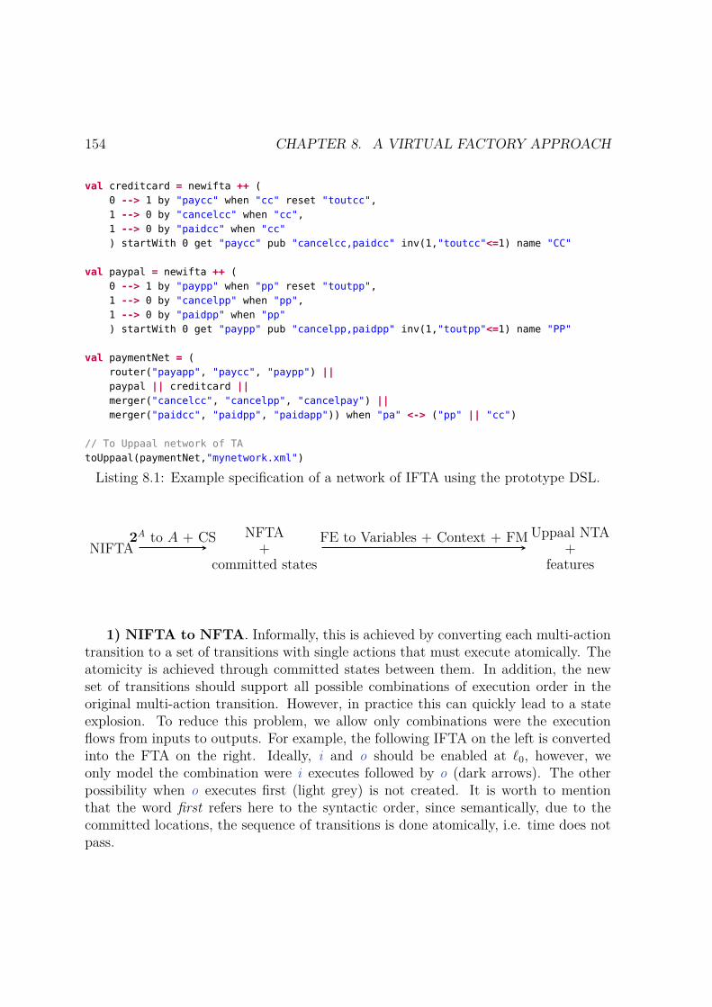
154 CHAPTER 8. A VIRTUAL FACTORY APPROACH
val creditcard = newifta ++ (0 --> 1 by "paycc" when "cc" reset "toutcc",1 --> 0 by "cancelcc" when "cc",1 --> 0 by "paidcc" when "cc") startWith 0 get "paycc" pub "cancelcc,paidcc" inv(1,"toutcc"<=1) name "CC"
val paypal = newifta ++ (0 --> 1 by "paypp" when "pp" reset "toutpp",1 --> 0 by "cancelpp" when "pp",1 --> 0 by "paidpp" when "pp") startWith 0 get "paypp" pub "cancelpp,paidpp" inv(1,"toutpp"<=1) name "PP"
val paymentNet = (router("payapp", "paycc", "paypp") ||paypal || creditcard ||merger("cancelcc", "cancelpp", "cancelpay") ||merger("paidcc", "paidpp", "paidapp")) when "pa" <-> ("pp" || "cc")
// To Uppaal network of TAtoUppaal(paymentNet,"mynetwork.xml")
Listing 8.1: Example specification of a network of IFTA using the prototype DSL.
NIFTANFTA+
committed states
Uppaal NTA+
features
2A to A + CS FE to Variables + Context + FM
1) NIFTA to NFTA. Informally, this is achieved by converting each multi-actiontransition to a set of transitions with single actions that must execute atomically. Theatomicity is achieved through committed states between them. In addition, the newset of transitions should support all possible combinations of execution order in theoriginal multi-action transition. However, in practice this can quickly lead to a stateexplosion. To reduce this problem, we allow only combinations were the executionflows from inputs to outputs. For example, the following IFTA on the left is convertedinto the FTA on the right. Ideally, i and o should be enabled at ℓ0, however, weonly model the combination were i executes followed by o (dark arrows). The otherpossibility when o executes first (light grey) is not created. It is worth to mentionthat the word first refers here to the syntactic order, since semantically, due to thecommitted locations, the sequence of transitions is done atomically, i.e. time does notpass.
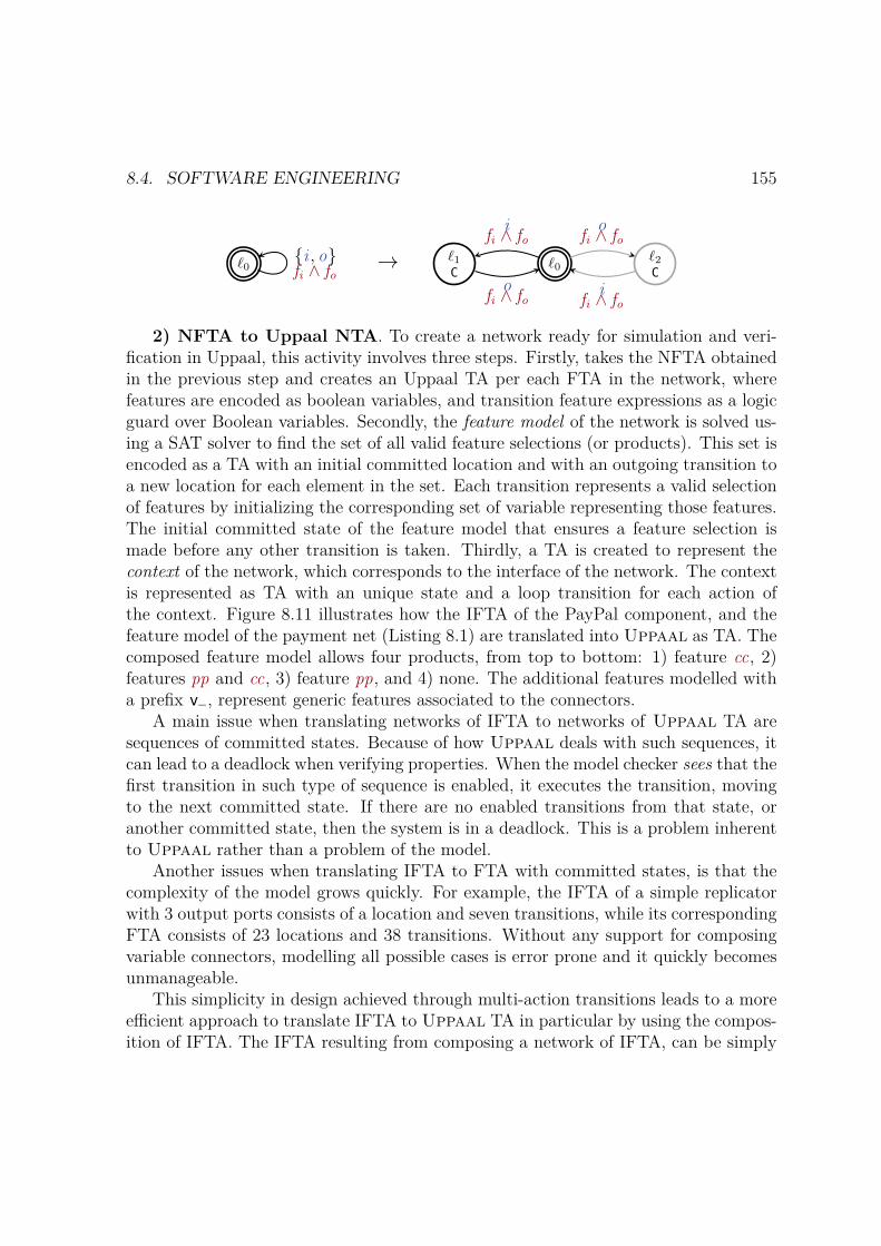
8.4. SOFTWARE ENGINEERING 155
ℓ0i , ofi ∧ fo
→ ℓ0ℓ2C
ℓ1C
ifi ∧ fo
ofi ∧ fo
ofi ∧ fo
ifi ∧ fo
2) NFTA to Uppaal NTA. To create a network ready for simulation and veri-fication in Uppaal, this activity involves three steps. Firstly, takes the NFTA obtainedin the previous step and creates an Uppaal TA per each FTA in the network, wherefeatures are encoded as boolean variables, and transition feature expressions as a logicguard over Boolean variables. Secondly, the feature model of the network is solved us-ing a SAT solver to find the set of all valid feature selections (or products). This set isencoded as a TA with an initial committed location and with an outgoing transition toa new location for each element in the set. Each transition represents a valid selectionof features by initializing the corresponding set of variable representing those features.The initial committed state of the feature model that ensures a feature selection ismade before any other transition is taken. Thirdly, a TA is created to represent thecontext of the network, which corresponds to the interface of the network. The contextis represented as TA with an unique state and a loop transition for each action ofthe context. Figure 8.11 illustrates how the IFTA of the PayPal component, and thefeature model of the payment net (Listing 8.1) are translated into Uppaal as TA. Thecomposed feature model allows four products, from top to bottom: 1) feature cc, 2)features pp and cc, 3) feature pp, and 4) none. The additional features modelled witha prefix v_, represent generic features associated to the connectors.
A main issue when translating networks of IFTA to networks of Uppaal TA aresequences of committed states. Because of how Uppaal deals with such sequences, itcan lead to a deadlock when verifying properties. When the model checker sees that thefirst transition in such type of sequence is enabled, it executes the transition, movingto the next committed state. If there are no enabled transitions from that state, oranother committed state, then the system is in a deadlock. This is a problem inherentto Uppaal rather than a problem of the model.
Another issues when translating IFTA to FTA with committed states, is that thecomplexity of the model grows quickly. For example, the IFTA of a simple replicatorwith 3 output ports consists of a location and seven transitions, while its correspondingFTA consists of 23 locations and 38 transitions. Without any support for composingvariable connectors, modelling all possible cases is error prone and it quickly becomesunmanageable.
This simplicity in design achieved through multi-action transitions leads to a moreefficient approach to translate IFTA to Uppaal TA in particular by using the compos-ition of IFTA. The IFTA resulting from composing a network of IFTA, can be simply

156 CHAPTER 8. A VIRTUAL FACTORY APPROACH
(a) PayPal as Uppaal TA
(b) Feature model as Uppaal TA
Figure 8.11: Example of an Uppaal TA consisting of the PayPal component (Fig-ure 8.8b), and the feature model of the payment net specified in Listing 8.1.
converted to an FTA by flattening the set of actions in to a single action, and laterinto an Uppaal TA, avoiding the use of committed states.
In addition to this translations, it is possible to convert the networks of IFTA andIFTA to an HTML file with JavaScript code. In this case, one may interactively selectfeatures and see how the selection affects the models, as it was illustrated in Section 7.2.
8.5 DiscussionThe aim of this chapter was to introduce the virtual factory approach for digital publicservice development. This is a conceptual framework for the rapid development ofdigital public services for a given smart city domain. The approach was illustrated bytaking the smart mobility dimension as a case study.
In particular, we proposed a taxonomy of smart mobility services which deals withthe understanding of the domain, the identification of types of services to be delivered,technologies used, public value delivered by the services, and stakeholders to whomthey can be delivered. Thus, it provides a tool for policy makers to plan and designsmart mobility services.
Through planning, it is possible to identify a concrete family of services. Firstly,

8.5. DISCUSSION 157
the virtual factory fixes the vocabulary of the domain, actors, documents, processes,involved in the delivery of the family, through ontologies to structure information. Fromthe ontology it follows immediately the features of the domain, which facilitates thecreation of a feature model. Secondly, the virtual factory proposes to use the vocabularyidentified to produce behavioural models and associate them to such features, makingit possible to verify properties of the services.
By using techniques from component-based and SPL development it is possible toquickly model the behaviour of the entire family in a compositional way, and to derivemodels of concrete services by selecting a desired set of features.
The approach suggested presents some advantages over other silo-based approachesthat can contribute to address some of the challenges discussed in Section 2.2.2. Inparticular:
– rapid development – by identifying families of services in a proactive mannerthrough the use of planning tools, and develop them using SPL techniques;
– service and business process integration – by using ontologies to standardize thevocabulary of the domain it can contribute to sharing information among dif-ferent government levels. In addition, the development of digital public servicesin a SPL brings the benefits of mass production and customization, contribut-ing to the easy adoption of standardized but customized solutions by differentlocal governments, facilitating sharing information across different agencies andgovernment levels;
– conformance with laws and regulations – by using formal methods to model ser-vices en verifying them against expected properties;
– usability – using an SPL approach can increase the quality of the deliveredproducts. Intuitively, the SPL enables to deliver products that can be quicklyadopted by many clients – more government agencies using the services in a fam-ily would lead to more feedback to improve the services which will increase thequality of the services.
– development costs – by using and SPL approach; and
– matching citizen needs – the use of a taxonomy to plan the delivery of servicescontributes to move to qualitative approach to deliver DPS to citizens, sincegovernments can identify first public value that needs to be delivered, instead ofdelivering services in a quantitative approach.
We envision a fourth component of the virtual factory, an implementation stage, toautomate the development of software applications implementing the structural and

158 CHAPTER 8. A VIRTUAL FACTORY APPROACH
behavioural models specified in the domain and software engineering stages. A feasibleapproach would be to define a formal model to link the structural elements of thedomain, and the behavioural and variability models with concrete code implementingthe specification provided by such models.
Finally, although not provided in this thesis, we envision a formal mechanism tolink each feature of the feature diagram with the structural elements of the domain,similar to the way IFTA uses feature expressions to annotate behavioural models. Inaddition, such a mechanism should link each structural element of the domain withcorresponding behavioural models. For example, in the case of the documents, thetypical behaviour to be supported is the CRUD cycle: creating, reading, updating,and deleting documents.

Chapter 9
Conclusions and Future Work
The aim of this research work was to provide a conceptual framework with tools forboth, government officials and software developers, to rapidly plan and design integ-rated smart city DPS on a specific city domain. In particular, by relying on softwareproduct line techniques and formal methods to address concrete challenges in the de-velopment of DPS, such as rapid development of software applications supporting thedelivery of DPS, service integration, reducing costs in service development, and ensur-ing conformance with laws and regulations. Further challenges were discussed in seeSection 2.2.2.
For the research problem defined in the thesis, the following research questionswhere formulated:
RQ1) What kind of smart mobility services are delivered in the context of smartcities?
RQ2) How are such services delivered?
RQ3) What kind of public value is delivered by smart mobility services and to whom?
RQ4) Which modelling technologies are suitable for specifying common features of afamily of digital public services delivered by local governments in the context ofsmart cities?
RQ5) Based on such modelling techniques, how to provide a domain-specific frame-work, including modelling tools that can automatically generate behaviouralmodels for the members of the identified family of digital public services?
RQ6) Which family of digital public services in the context of smart mobility is amend-able to be deliver through common business processes by local governments indifferent contextual conditions?
159
160 CHAPTER 9. CONCLUSIONS AND FUTURE WORK
In order to understand the background of the domain we began by exploring DPSacross the various dimensions of a smart city. However, we focused on smart mobility,due to the positive impact theses services have in the development of smart cities, asdiscussed in Section 2.4. We conducted a state of the art review to address researchquestions RQ1, RQ2 and RQ3, and consolidated the findings in a taxonomy of smartmobility service. The taxonomy serves as a tool for government practitioners, suchas policy makers and government officials involved in the strategic planning of smartmobility initiatives, by identifying types of services to be delivered, stakeholders towhom deliver such services, and public value delivered, facilitating the definition ofbusiness cases for developing initiatives, as well as for prioritizing what services shouldbe delivered. In addition, the taxonomy provides a common vocabulary to describe,discuss and share information about smart mobility initiatives, which can contributeto the sharing of knowledge and good practices among different governments. Furtherusages of the taxonomy by different stakeholders was discussed in Section 8.2.
The taxonomy also contributed to address RQ6. Most of the services identifiedby the taxonomy were developed by non-government entities or co-created betweengovernment and non-government entities. In this sense, the role of government seemsto move away from service provider, to become an enabler and regulator of such services.With this in mind, and the fact that governments must ensure the provision of publictransport services as a basic service to city residents , we identified a family of licensingpublic transports services to serve as a concrete case study. Licenses help government toensure the provision of services complies with the established regulations. In addition,they are provided by local governments worldwide, and as such, are widely used bygovernments with different levels of resources and legal backgrounds.
To understand how services in the identified family were being delivered, we studiedlicensing public bus passenger services in two countries, Ireland and Portugal. Fromthe analysis we identified 1) licenses required for the provision of such services, 2)documentation required for the application of each license, 3) entities involved in theprovision of the licensing services, and 4) application process activities. In order to fix acommon vocabulary for the domain, in particular considering the structural properties,we proposed an ontology of licensing public transport services, modelling structuralelements, their attributes, and relationships.
The main aim of the ontology was to facilitate the definition of generic structuralmodels for the given family. The ontology will serve to relate the structural models withbehavioural models and parametrize both by features. This will be further explore asfuture work. The development of the ontology contributed to a better understanding ofthe domain and due to the standardizing nature of ontologies, it serves other purposesas well, including: the automation of service features so to facilitate the transitionfrom paper-based delivery channels to electronic ones and the integration of different

161
licensing systems; and improving government interoperability.As mentioned, during the analysis of the family we identified the processes required
to obtain and issue the licences. At this stage, it was evident that time was a recur-rent requirement for the analysed services and that processes were distributed acrossvarious actors, which required service coordination. Thus, we studied SPL modellingformalisms that could deal with such requirements. We identified FTA as a promisingformalism which included tools for verification. However, since FTA is a fine grainapproach to model SPL, it could not deal with model composition. As discussed inSection 4.1.2, modelling complex SPLs requires modular and scalable modelling form-alisms. In particular, the complex nature of DPS due to the different stakeholdersand processes involved in their delivery, requires a specification formalism capable ofsimplifying their design, as well as, of delegating the modelling of different processes tothe relevant stakeholders. The simplification can be achieved, for example, by dividingfunctionality into simpler modules. The findings of this stage contributed to answerthe research question RQ4. Details of the proposed solution are explained below
We proposed a compositional formalism, IFTA, based on FTA. The formalism ex-plicitly defines interfaces for the models, which restrict the way automata interact.This interfaces are variable, i.e. they are parametrized by features and may not bepresent in every product that can be derived from the SPL. The main contributionof IFTA is its compositionality, which makes possible the incremental design of SPLs.We argue that this is a truly compositional formalism in the sense that it composesfamilies of systems, instead of products, as most approaches do in the literature (seeSection 4.1.2). In addition, because composition composes variability as well, it ispossible to verify if the set of products that can be derived from the composed systemit is the intended. We implemented a proof-of-concept prototype to specify, compose,visualize, and translate IFTA models to other formalisms. The most relevant func-tionalities of the prototype are the translation of models into Uppaal networks ofTA, which enables the verification of behavioural properties over the models; and theinteractive visualization of IFTA and networks of IFTA, which enable to quickly seewhich are the valid set of products that can be derived from the models, and how eachparticular selection affects them. In particular, it is possible to visualize how featureselections affect transitions, in the case of IFTA models, and interfaces and connectionsbetween different components, in the case of networks of IFTA.
Towards addressing the issue of delegating the design and development of systemsto various stakeholders, we proposed a refinement relation for IFTA. The relationserves to compare two IFTA – one representing an abstract model specifying a familyof systems, and another representing a more detailed implementation of such specific-ation; and it helps to determine if the implementation can replace the specificationin every environment where the specification is used, to obtain a congruent system.
162 CHAPTER 9. CONCLUSIONS AND FUTURE WORK
The are various notions of refinement that could have been considered as discussedin Section 6.2, each with its advantages and limitations. Here we opted for defining arelation that maintains the reactivity of the systems, i.e. it ensures that the implement-ation can react to the same inputs than the specification, and that it will not produceunexpected outputs. In this trade-off, the relation does not ensures that the imple-mentation preserves safety properties of the specification. The relation is a pre-orderand compositional. The latter allows decomposition of refinement proofs, improvingefficiency in refinement checking. However, to simplify the definition, we separated thenotion of variability refinement from behavioural refinement, which entails to conductrefinement proofs following a product-by-product approach, hindering efficiency. Thus,we proposed as well a variability-aware refinement relation that can be applied overthe entire family.
Related to the modular and scalable approach to model SPLs, and the need tocoordinate services with variable interfaces, we studied Reo, an exogenous coordin-ation language to orchestrate how components interact through their interfaces. Inaccordance with the principles of SPL, namely the development of reusable assets forsystematic reuse in the development of products, we argue that exogenous coordina-tion presents an opportunity for increasing the reusability of both, domain models, andmodels of the coordination protocols used to orchestrate them. Since in our case, com-ponents have variable interfaces, coordination protocols need to adapt to their presenceor absence. We proposed to model Reo connectors as IFTA, providing them with avariable semantics. The original intention was to enable protocols to automatically ad-apt their variability based on the variability of the components they interact. However,in practice, this is not a simple task, and it required to model connectors with differ-ent degrees of variability depending the case. In particular we proposed two differentapproaches to model Reo, a conservative and a relaxed one, offering different degreesof variability. However, other approaches may be required. In practice, connectorsfrom both approaches are combined to achieve an expected outcome. Nevertheless,using IFTA to model connectors simplifies significantly the design of coordination pro-tocols. The prototype developed was of utmost help to visualize complex coordinationprotocols and understand which approach should be used for modelling each connector.
Finally, we introduced the concept of a virtual factory, which aims at facilitatingthe rapid development of models and software applications supporting the delivery ofDPS. This contributed to address RQ5. The virtual factory seeks to shift the paradigmfrom silo-based development of services to a component-based development, by identi-fying families of services from an early stage and accompanying various stakeholdersthrough the various stages in the development of DPS. The concept relies on threeprinciples: 1) service family specific - the virtual factory is configurable for a givenfamily, in the case of this thesis, for a family of licensing of public transport services;

163
2) scalable it can be extended with other components; and 3) generalizable it can beapplicable to other families. In this thesis, we populate the virtual factory with com-ponents that contribute to the planning, domain engineering, and software engineeringstages of DPS development of smart mobility services. In particular, the taxonomycontributed to the strategic planning of smart mobility initiatives; the ontology con-tributed to the domain engineering stage by providing structural models and fixinga common vocabulary for the concrete family; and the specification formalism, IFTAand related contributions, namely the refinement relation, models for Reo, and theproof-of-concept prototype, contributed to the software engineering stage, providingmechanism to specify behavioural aspects of DPS and verify properties.
Future Work
The research conducted as part of this thesis enables to define several problems to beexplored as future work, as discussed below.
The taxonomy of smart mobility services introduced in Section 3.3 can be extendedand improved following guidelines and suggestions provided in Section 3.5.
The ontology introduced in Section 8.3 can be formalized using the W3C WebOntology Language1 (OWL) to verify properties such as consistency, or to infer newknowledge. In addition, as envisioned, it is necessary to define a mechanism to associ-ate the ontology elements with variability, as well as with behavioural models relatedto such elements. A possible path is to define a meta-ontology comprising products, towhich we associate elements which correspond to structural elements of the domain.Then, we can associate behavioural models to such elements, and finally, we associatefeatures to elements and behavioural models. With the assistance of a feature modeldocumenting valid feature combinations, the envision mechanism should enable select-ing a product, for example a concrete public transport license like transport operator,and infer which features are available for such product. Finally, based on a concretefeature selection, to offer tools to derive the concrete structural and behavioural modelsfor the selected features.
Regarding IFTA, there are many opportunities for exploration particularly con-cerning refinement. As discussed in Chapter 6 it is of interest to study other alternat-ives of behavioural and variability refinement. In particular, exploring how these newdefinitions affect the properties that we can expect from a refinement relation, mainlyregarding compositionality and the properties that the implementation can preservefrom the specification. In the case of variability refinement, one possibility to exploreis to allow the feature model of the implementation to introduce new behaviour throughnew features, which would align better with the notion of behavioural refinement. In
1https://www.w3.org/standards/techs/owl
164 CHAPTER 9. CONCLUSIONS AND FUTURE WORK
the case of behavioural refinement, simulation relations are usually used as refinementrelations. Such relation preserves safety properties at the expense of allowing the im-plementation to react to less inputs. It would be interesting to explore if a new notionof refinement can be achieved for families of IFTA, to preserve both, the reactivity ofthe system and the safety properties satisfied from the specification. In addition, otherways of composing feature models can be explored when defining IFTA composition.
Another area of exploration for IFTA are Reo models. As discussed, in practicedifferent degrees of variability are required depending on the context. As future work,other approaches to model Reo connectors can be explored to simplify even more thedefinition of these protocols taking away the burden from the user from selecting theright approach. A possible path can be to work on a constraint solver to automaticallysuggest variability restrictions in order to achieve a given desired outcome.
Finally, regarding the virtual factory, new components can be added such as: aDomain Specific Language for domain users (non-software engineers) to easily specifyservices; a mechanism for automatic code generation based on structural and behavi-oural models; a suitable logic for specifying and verifying structural properties of thedomain; and its adaptation to other domains of a smart city and other families withinthe smart mobility domain.

Bibliography
[1] M. Acher, P. Collet, P. Lahire, and R. France. Composing feature models. InM. van den Brand, D. Gašević, and J. Gray, editors, Software Language Engin-eering, pages 62–81, Berlin, Heidelberg, 2010. Springer Berlin Heidelberg.
[2] A. Aldama-Nalda, H. Chourabi, T. a. Pardo, J. R. Gil-Garcia, S. Mellouli, H. J.Scholl, S. Alawadhi, T. Nam, and S. Walker. Smart cities and service integrationinitiatives in North American cities. In Proceedings of the 13th Annual Interna-tional Conference on Digital Government Research, page 289, New York, NewYork, USA, 2012. ACM Press.
[3] L. Allulli, G. F. Italiano, and F. Santaroni. Exploiting GPS Data in PublicTransport Journey Planners. In 13th International Symposium on ExperimentalAlgorithms, 2014.
[4] R. Alur and D. L. Dill. A theory of timed automata. Theoretical ComputerScience, 126(2):183 – 235, 1994.
[5] R. Alur, T. A. Henzinger, O. Kupferman, and M. Y. Vardi. Alternating refine-ment relations, pages 163–178. Springer Berlin Heidelberg, Berlin, Heidelberg,1998.
[6] G. Anastasi, M. Antonelli, A. Bechini, S. Brienza, E. D’Andrea, D. De Guglielmo,P. Ducange, B. Lazzerini, F. Marcelloni, and A. Segatori. Urban and socialsensing for sustainable mobility in smart cities. 2013 Sustainable Internet andICT for Sustainability, SustainIT 2013, 2013.
[7] S. Apel, D. Batory, C. Kstner, and G. Saake. Feature-Oriented Software ProductLines: Concepts and Implementation. Springer Publishing Company, Incorpor-ated, 2013.
[8] S. Apel, H. Speidel, P. Wendler, A. von Rhein, and D. Beyer. Detection offeature interactions using feature-aware verification. In Proceedings of the 2011
165

166 BIBLIOGRAPHY
26th IEEE/ACM International Conference on Automated Software Engineering,ASE ’11, pages 372–375, Washington, DC, USA, 2011. IEEE Computer Society.
[9] F. Arbab. Reo: a channel-based coordination model for component composition.Mathematical Structures in Computer Science, (3):329–366, 2004.
[10] F. Arbab. Puff, The Magic Protocol, pages 169–206. Springer Berlin Heidelberg,Berlin, Heidelberg, 2011.
[11] F. Arbab, C. Baier, F. de Boer, and J. Rutten. Models and temporal logicalspecifications for timed component connectors. Software & Systems Modeling,6(1):59–82, Mar 2007.
[12] F. Arbab, N. Kokash, and S. Meng. Towards Using Reo for Compliance-AwareBusiness Process Modeling, pages 108–123. Springer Berlin Heidelberg, Berlin,Heidelberg, 2008.
[13] F. Arbab and J. J. M. M. Rutten. A Coinductive Calculus of Component Con-nectors, pages 34–55. Springer Berlin Heidelberg, Berlin, Heidelberg, 2003.
[14] R. Arnott and E. Inci. An integrated model of downtown parking and trafficcongestion. Journal of Urban Economics, 60(3):418–442, 2006.
[15] C. Baier. Probabilistic models for reo connector circuits. Journal of UniversalComputer Science (J. UCS), 11(10):1718–1748, oct 2005.
[16] C. Baier, J.-P. Katoen, and K. G. Larsen. Principles of model checking. 2008.
[17] C. Baier, M. Sirjani, F. Arbab, and J. Rutten. Modeling component connectorsin reo by constraint automata. Sci. Comput. Program., 61(2):75–113, July 2006.
[18] K. D. Bailey. Typologies and Taxonomies: An Introduction to ClassificationTechniques. Number 07. 1994.
[19] M. Bakillah, S. H. L. Liang, and A. Zipf. Toward coupling sensor data andvolunteered geographic information (VGI) with agent-based transport simula-tion in the context of smart cities. Proceedings of the First ACM SIGSPATIALWorkshop on Sensor Web Enablement - SWE ’12, pages 17–23, 2012.
[20] F. Bannister and D. Wilson. O(Ver)-Government?: Emerging Technology, Cit-izen Autonomy and the Regulatory State. Information Polity, 16(1):63–79, Jan.2011.

BIBLIOGRAPHY 167
[21] R. Barrero, J. V. Mierlo, and X. Tackoen. Enhanced Energy Storage Systems forImproved On-Board Light Rail Vehicle Efficiency. IEEE Vehicular TechnologyMagazine, (September):26–36, 2008.
[22] D. Batory, J. N. Sarvela, and A. Rauschmayer. Scaling step-wise refinement.IEEE Transactions on Software Engineering, 30(6):355–371, 2004.
[23] D. Benavides, S. Segura, and A. Ruiz-Cortés. Automated analysis of featuremodels 20 years later: A literature review. Inf. Syst., 35(6):615–636, Sept. 2010.
[24] C. Benevolo, R. P. Dameri, and B. D. Auria. Smart Mobility in Smart City -Action Taxonomy, ICT Intensity and Public Benefits. 11:13–29, 2016.
[25] J. Bengtsson and W. Yi. Timed Automata: Semantics, Algorithms and Tools,pages 87–124. Springer Berlin Heidelberg, Berlin, Heidelberg, 2004.
[26] J. Bertot, E. Estevez, and T. Janowski. Universal and contextualized publicservices: Digital public service innovation framework. Government InformationQuarterly, 33(2):211–222, 2016.
[27] P. Blythe. RFID for road tolling, road-use pricing and vehicle access control. InIEE Colloquium (Digest), number 123, pages 67–82, 1999.
[28] D. Bruno and H. Richmond. The Truth About Taxonomies. Information Man-agement Journal, 37(2):44–53, 2003.
[29] C. Busold, A. Taha, C. Wachsmann, A. Dmitrienko, H. Seudié, M. Sobhani,and A.-R. Sadeghi. Smart keys for cyber-cars: secure smartphone-based NFC-enabled car immobilizer. Proceedings of the third ACM conference on Data andapplication security and privacy, pages 233–242, 2013.
[30] J. Candamo, M. Shreve, D. Goldgof, D. Sapper, and R. Kasturi. UnderstandingTransit Scenes: A Survey on Human Behavior-Recognition Algorithms. IEEETransactions on Intelligent Transportation Systems, 11(1):206–224, mar 2010.
[31] E. M. Cepolina and A. Farina. A new shared vehicle system for urban areas.Transportation Research Part C: Emerging Technologies, 21(1):230–243, 2012.
[32] S. L. Cisco and W. K. Jackson. Creating Order out of Chaos with Taxonomies.Information Management Journal, 39(3):44–50, 2005.
168 BIBLIOGRAPHY
[33] D. Clarke, D. Costa, and F. Arbab. Connector colouring i: Synchronisation andcontext dependency. Science of Computer Programming, 66(3):205 – 225, 2007.Special Issue on the 4th International Workshop on Foundations of CoordinationLanguages and Software Architectures (FOCLASA 05).
[34] A. Classen, Q. Boucher, and P. Heymans. A text-based approach to featuremodelling: Syntax and semantics of tvl. Sci. Comput. Program., 76(12):1130–1143, Dec. 2011.
[35] A. Classen, P. Heymans, P.-Y. Schobbens, and A. Legay. Symbolic model check-ing of software product lines. International Conference on Software Engineering,ICSE, pages 321–330, 2011.
[36] A. Classen, P. Heymans, P.-Y. Schobbens, A. Legay, and J.-F. Raskin. Modelchecking lots of systems: efficient verification of temporal properties in softwareproduct lines. In Proceedings of the 32nd ACM/IEEE International Conferenceon Software Engineering-Volume 1, pages 335–344. ACM, 2010.
[37] G. Cledou. A proof-of-concept prototype for ifta. Technical report, HASLabINESCTEC and University of Minho.
[38] G. Cledou. A virtual factory for smart city service integration. In Proceedingsof the 8th International Conference on Theory and Practice of Electronic Gov-ernance, ICEGOV ’14, pages 536–539, New York, NY, USA, 2014. ACM.
[39] G. Cledou and L. S. Barbosa. An ontology for licensing public transport services.Technical report, HASLab INESCTEC and University of Minho.
[40] G. Cledou and L. S. Barbosa. An ontology for licensing public transport services.In Proceedings of the 9th International Conference on Theory and Practice ofElectronic Governance, ICEGOV ’15-16, pages 230–239, New York, NY, USA,2016. ACM.
[41] G. Cledou and L. S. Barbosa. Modeling families of public licensing services: Acase study. In Proceedings of the 5th International FME Workshop on FormalMethods in Software Engineering, FormaliSE ’17, pages 37–43, Piscataway, NJ,USA, 2017. IEEE Press.
[42] G. Cledou, E. Estevez, and L. S. Barbosa. A taxonomy for planning and design-ing smart mobility services. Government Information Quarterly, 35(1):61 – 76,2018. Internet Plus Government: Advancement of Networking Technology andEvolution of the Public Sector.

BIBLIOGRAPHY 169
[43] G. Cledou, J. Proença, and L. S. Barbosa. A refinement relation for familiesof timed automata. In S. Cavalheiro and J. Fiadeiro, editors, Formal Methods:Foundations and Applications, pages 161–178, Cham, 2017. Springer Interna-tional Publishing.
[44] G. Cledou, J. Proença, and L. Soares Barbosa. Composing families of timedautomata. In M. Dastani and M. Sirjani, editors, Fundamentals of SoftwareEngineering, pages 51–66, Cham, 2017. Springer International Publishing.
[45] P. Clements and L. Northrop. Software product lines. Addison-Wesley, 2002.
[46] M. Cordy. Model Checking for the Masses. PhD thesis, 2014.
[47] M. Cordy, P.-Y. Schobbens, P. Heymans, and A. Legay. Behavioural modellingand verification of real-time software product lines. In Proceedings of the 16thInternational Software Product Line Conference-Volume 1, pages 66–75. ACM,2012.
[48] M. Cordy, P. Y. Schobbens, P. Heymans, and A. Legay. Beyond Boolean product-line model checking: Dealing with feature attributes and multi-features. Proceed-ings - International Conference on Software Engineering, pages 472–481, 2013.
[49] E. Daniel and J. Ward. Integrated service delivery: exploratory case studies ofenterprise portal adoption in uk local government. Business Process ManagementJournal, 12(1):113–123, 2006.
[50] A. David, K. G. Larsen, A. Legay, U. Nyman, and A. Wasowski. Timed i/oautomata: A complete specification theory for real-time systems. In Proceedingsof the 13th ACM International Conference on Hybrid Systems: Computation andControl, HSCC ’10, pages 91–100, New York, NY, USA, 2010. ACM.
[51] S. M. Davis. Future perfect. Basic Books, 1997.
[52] L. de Alfaro and T. A. Henzinger. Interface automata. SIGSOFT Softw. Eng.Notes, 26(5):109–120, Sept. 2001.
[53] L. de Alfaro and T. A. Henzinger. Interface-Based Design, pages 83–104. SpringerNetherlands, Dordrecht, 2005.
[54] Department of Transport Tourism and Sport. Transport Operator License -Guidelines and Forms. https://www.rtol.ie/rtol-online/forms. Accessed:2015-05-20.

170 BIBLIOGRAPHY
[55] A. V. Deursen. Where to Go in the Near Future : Diverging Perspectives on On-line Public Service Delivery. In Electronic Government, pages 143–154. SpringerBerlin Heidelberg, 2007.
[56] A. V. Deursen, J. V. Dijk, and W. Ebbers. Why E-government Usage LagsBehind : Explaining the Gap between Potential and Actual Usage of ElectronicPublic Services in the Netherlands. In Electronic Government, pages 269–280.Springer Berlin Heidelberg, 2006.
[57] Deutsche Gesellschaft für Internationale Zusammenarbeit. Urban Transport andEnergy Efficiency. 2012.
[58] S. Djahel, N. Smith, S. Wang, and J. Murphy. Reducing Emergency ServicesResponse Time in Smart Cities : An Advanced Adaptive and Fuzzy Approach.(October), 2015.
[59] C. Dobre and F. Xhafa. Intelligent services for Big data science. Future Gener-ation Computer Systems, 37:267–281, 2014.
[60] V. Douwe, E. Estevez, A. Ojo, and T. Janowski. Software infrastructure foreŋgovernment ŋ- Eŋ-appointment service. Communications in Computer andInformation Science, 62:141–152, 2009.
[61] E. Estevez. Programmable Messaging for Electronic Government. PhD thesis,Universidad Nacional del Sur, 2009.
[62] E. Estevez. EGOV Infrastructure and Services, Executive Training for Govern-ment Information Officers, Module 5, 2014.
[63] E. Estevez and T. Janowski. Building a dependable messaging infrastructure forelectronic government. In 2nd International Conference on Availability, Reliab-ility and Security, ARES, pages 948–955, 2007.
[64] European Commission. EU eGovernment Action Plan 2016-2020. https://ec.europa.eu/digital-single-market/en/european-egovernment-action-plan-2016-2020. Accessed: 2018-05-17.
[65] European Commission. European Interoperability Framework for Pan-EuropeaneGovernment Services, 2004.
[66] EY and Danish Technological Institute. Study on eGovernment and the Reductionof Administrative Burden. 2014.
BIBLIOGRAPHY 171
[67] M. Fang and C. Jianping. A Novel System for Interactive Mobile MultimediaService in Public Transports. pages 867–870, 2013.
[68] B. Fazenda, H. Atmoko, F. G. F. Gu, L. G. L. Guan, and a. Ball. Acousticbased safety emergency vehicle detection for intelligent transport systems. 2009Iccas-Sice, (1):4250–4255, 2009.
[69] J. Firnkorn and M. Müller. What will be the environmental effects of new free-floating car-sharing systems? The case of car2go in Ulm. Ecological Economics,70(8):1519–1528, 2011.
[70] R. Giffinger, C. Fertner, H. Kramar, R. Kalasek, P.-M. Natasa, and E. Meijers.Smart cities Ranking of European medium-sized cities. October, 16(October):13–18, 2007.
[71] P. Gora. A genetic algorithm approach to optimization of vehicular traffic incities by means of configuring traffic lights. Studies in Computational Intelligence,369:1–10, 2011.
[72] P. Gora and P. Wasilewski. Adaptive System for Intelligent Traffic Managementin Smart Cities. In D. Ślęzak, G. Schaefer, S. Vuong, and Y.-S. Kim, editors,Active Media Technology SE - 44, volume 8610 of Lecture Notes in ComputerScience, pages 525–536. Springer International Publishing, 2014.
[73] P. Gottschalk. Maturity levels for interoperability in digital government. Gov-ernment Information Quarterly, 26(1):75–81, Jan. 2009.
[74] D. F. Gray. Introduction to the Formal Design of Real Time Systems. Springer-Verlag London, 1999.
[75] M. L. Griss, J. Favaro, and M. d’Alessandro. Integrating feature modeling withthe rseb. In Proceedings. Fifth International Conference on Software Reuse (Cat.No.98TB100203), pages 76–85, Jun 1998.
[76] R. E. Hall, J. Braverman, J. Taylor, and H. Todosow. The Vision of A SmartCity. In 2nd International Life Extension Technology Workshop, Paris, France,2000.
[77] J. Harper, R. Fuller, D. Sweeney, and T. Waldmann. Human factors in technologyreplacement: A case study in interface design for a public transport monitoringsystem. Applied Ergonomics, 1998.
172 BIBLIOGRAPHY
[78] C. Harrison, B. Eckman, R. Hamilton, P. Hartswick, J. Kalagnanam, J. Para-szczak, and P. Williams. Foundations for Smarter Cities. IBM Journal of Re-search and Development, 54(4):1–16, jul 2010.
[79] G. Hinterwälder, C. T. Zenger, F. Baldimtsi, A. Lysyanskaya, C. Paar, andW. P. Burleson. Efficient e-cash in practice: NFC-based payments for publictransportation systems. Lecture Notes in Computer Science (including subseriesLecture Notes in Artificial Intelligence and Lecture Notes in Bioinformatics),7981 LNCS:40–59, 2013.
[80] G.-J. Horng, J.-P. Li, and S.-T. Cheng. Traffic congestion reduce mechanismby adaptive road routing recommendation in smart city. 2013 3rd InternationalConference on Consumer Electronics, Communications and Networks, pages 714–717, nov 2013.
[81] Instituto da Mobilidade e dos Transportes IP. Carreiras de ServiçoPúblico - Guidelines and Forms. http://www.imtt.pt/sites/IMTT/Portugues/TransportesRodoviarios/TransportePublicoPassageiros/CarreirasServicoPublico/Paginas/CarreirasdeServiçoPublico.aspx.Accessed: 2015-05-20.
[82] Instituto da Mobilidade e dos Transportes IP. Licenciamento deEmpresas - Guidelines and Forms. http://www.imtt.pt/sites/IMTT/Portugues/TransportesRodoviarios/TransportePublicoPassageiros/LicenciamentoEmpresas/Paginas/LicenciamentoEmpresas.aspx. Accessed:2015-05-20.
[83] Instituto da Mobilidade e dos Transportes IP. Licenciamento de Veículos -Guidelines and Forms. Accessed: 2015-11-01.
[84] Ireland’s National Police Service. Licensing of Large Public Service Vehicles -Requirements. http://www.garda.ie/Controller.aspx?Page=100. Accessed:2015-05-20.
[85] Ireland’s National Transport Authority. Licensing of Public Bus Passen-ger Services - Guidelines and Forms. https://www.nationaltransport.ie/taxi-and-bus-licensing/bus/. Accessed: 2015-11-01.
[86] T. Janowski. Digital government evolution: From transformation to contextual-ization. Government Information Quarterly, 32(3):221–236, 2015.
BIBLIOGRAPHY 173
[87] T. Janowski, A. Ojo, and E. Estevez. Rapid Development of Electronic PublicServices — Software Infrastructure and Software Process. In 8th Annual Inter-national Digital Government Research Conference Rapid, pages 294–295, 2007.
[88] T. Janowski, A. Ojo, and E. Estevez. Rapid development of electronic publicservices: Software infrastructure and software process. In Proceedings of the 8thannual international conference on Digital government research: bridging discip-lines & domains, pages 294–295. Digital Government Society of North America,2007.
[89] M. Janssen and E. Estevez. Lean Government and Platform-based Governance- Doing More with Less. Government Information Quarterly, 30(1):S1–S8, jan2013.
[90] Z. Ji, I. Ganchev, M. O’Droma, L. Zhao, and X. Zhang. A Cloud-Based CarParking Middleware for IoT-based Smart Cities: Design and Implementation.Sensors, 14(12):22372–22393, 2014.
[91] S.-S. T. Q. Jongmans and F. Arbab. Overview of thirty semantic formalisms forreo. Sci. Ann. Comp. Sci., 22:201–251, 2012.
[92] T. B. Jørgensen and B. Bozeman. Public Values - An Inventory. Adminsitration& Society, 39(3):354–381, 2007.
[93] M. Jung, J. Weidinger, W. Kastner, and A. Olivieri. Building Automation andSmart Cities: An Integration Approach Based on a Service-Oriented Architec-ture. 27th International Conference on Advanced Information Networking andApplications Workshops, pages 1361–1367, Mar. 2013.
[94] K. C. Kang, S. G. Cohen, J. A. Hess, W. E. Novak, and A. S. Peterson. Feature-oriented domain analysis (foda) feasibility study. Technical report, SoftwareEngineering Institute, Carnegie-Mellon University, 1990.
[95] K. C. Kang, S. Kim, J. Lee, K. Kim, E. Shin, and M. Huh. Form: A feature-oriented reuse method with domain-specific reference architectures. Ann. Softw.Eng., 5(1):143–168, Jan. 1998.
[96] E. I. A. Kareem and A. Jantan. An intelligent traffic light monitor system usingan adaptive associative memory. International Journal of Information Processingand Management, 2(2):23–39, 2011.

174 BIBLIOGRAPHY
[97] C. Kästner, S. Apel, and M. Kuhlemann. Granularity in software product lines.In Proceedings of the 30th International Conference on Software Engineering,ICSE ’08, pages 311–320, New York, NY, USA, 2008. ACM.
[98] D. Kitchin, W. R. Cook, and J. Misra. A language for task orchestration andits semantic properties. In C. Baier and H. Hermanns, editors, CONCUR 2006– Concurrency Theory, pages 477–491, Berlin, Heidelberg, 2006. Springer BerlinHeidelberg.
[99] J. Kostiainen, C. Erkut, and F. B. Piella. Design of an audio-based mobile journeyplanner application. Proceedings of the 15th International Academic MindTrekConference on Envisioning Future Media Environments - MindTrek ’11, page107, 2011.
[100] H. Kung and D. Vlah. Efficient location tracking using sensor networks. 2003IEEE Wireless Communications and Networking, 2003. WCNC 2003., 3, 2003.
[101] B. H. Kwasnik. The Role of Classifiction in Knowledge Representation and Dis-covery. Library Trends, 48(1):22–47, 1999.
[102] M. Ladeira, F. Michel, and L. Senna. Public Transport Monitoring and Control:The Case of Porto Alegre, Brazil. ICTIS 2011, pages 275–281, 2011.
[103] K. G. Larsen, U. Nyman, and A. Wasowski. Modal i/o automata for interfaceand product line theories. In European Symposium on Programming, pages 64–79.Springer, 2007.
[104] K. Layne and J. Lee. Developing fully functional E-government: A four stagemodel. Government Information Quarterly, 18(2):122–136, 2001.
[105] F. Li and B. Li. Aggregating heterogeneous services in the smart city: Thepractice in china. Lecture Notes in Computer Science (including subseries Lec-ture Notes in Artificial Intelligence and Lecture Notes in Bioinformatics), 10135LNCS:449–458, 2017.
[106] L. Li, F.-Y. Wang, N.-N. Zheng, and Y. Zhang. Research and developmentsof intelligent driving behaviour analysis. Zidonghua Xuebao/Acta AutomaticaSinica, 2007.
[107] V. M. A. d. Lima, R. M. Marcacini, M. H. P. Lima, M. I. Cagnin, and M. A. S.Turine. A generation environment for front-end layer in e-government content

BIBLIOGRAPHY 175
management systems. In Proceedings of the 2014 9th Latin American Web Con-gress, LA-WEB ’14, pages 119–123, Washington, DC, USA, 2014. IEEE Com-puter Society.
[108] M. Lochau, S. Mennicke, H. Baller, and L. Ribbeck. Incremental model checkingof delta-oriented software product lines. Journal of Logical and Algebraic Methodsin Programming, (1):245–267, 2016.
[109] M. Mallus, G. Colistra, L. Atzori, M. Murroni, and V. Pilloni. Dynamic car-pooling in urban areas: Design and experimentation with a multi-objective routematching algorithm. Sustainability (Switzerland), 9(2), 2017.
[110] M. Mannion. Using first-order logic for product line model validation. In Proceed-ings of the Second International Conference on Software Product Lines, SPLC 2,pages 176–187, London, UK, UK, 2002. Springer-Verlag.
[111] J.-V. Millo, S. Ramesh, S. N. Krishna, and G. K. Narwane. Compositionalverification of evolving software product lines. arXiv preprint arXiv:1212.4258,2012.
[112] E. a. Morris. Should we all just stay home? Travel, out-of-home activities, and lifesatisfaction. Transportation Research Part A: Policy and Practice, 78:519–536,2015.
[113] G. Motta, D. Sacco, A. Belloni, and L. You. A system for green personal integ-rated mobility: A research in progress. Proceedings of 2013 IEEE InternationalConference on Service Operations and Logistics, and Informatics, SOLI 2013,pages 1–6, 2013.
[114] G. Motta, L. You, D. Sacco, and G. Miceli. Mobility Service Systems : guidelinesfor a possible paradigm and a case study. In Proceedings of 2014 IEEE Inter-national Conference on Service Operations and Logistics, and Informatics, SOLI2014, number Figure 1, pages 48–53, 2014.
[115] R. Muschevici, J. Proença, and D. Clarke. Feature nets: behavioural modellingof software product lines. Software & Systems Modeling, pages 1–26, 2015.
[116] T. Nam and T. a. Pardo. Conceptualizing Smart City with Dimensions of Tech-nology, People, and Institutions. In Proceedings of the 12th Annual InternationalDigital Government Research Conference on Digital Government Innovation inChallenging Times - dg.o ’11, page 282, New York, New York, USA, 2011. ACMPress.
176 BIBLIOGRAPHY
[117] S. Nawaz, C. Efstratiou, and C. Mascolo. ParkSense: a smartphone based sens-ing system for on-street parking. Proceedings of the 19th annual internationalconference on Mobile computing and networking - Mobicom ’13, 2013.
[118] P. Neirotti, A. De Marco, A. C. Cagliano, G. Mangano, and F. Scorrano. Currenttrends in Smart City initiatives: Some stylised facts. Cities, 38:25–36, jun 2014.
[119] J. D. Nelson and C. Mulley. The impact of the application of new technologyon public transport service provision and the passenger experience: A focus onimplementation in Australia. Research in Transportation Economics, 39(1):300–308, 2013.
[120] R. C. Nickerson, U. Varshney, and J. Muntermann. A method for taxonomydevelopment and its application in information systems. European Journal ofInformation Systems, 22(3):336–359, 2012.
[121] S. Noei and A. Sargolzaei. Reducing Traffic Congestion Using Geo-fence Tech-nology : Application for Emergency Car. pages 15–20, 2014.
[122] OECD. Recommendation of the Council on Digital Government Strategies. Pub-lic Governance and Territorial Development Directorate, July:12, 2014.
[123] J. Opiola and S. Wilson. Bank payments in transportation - freedom and interop-erability for congestion pricing. In 15th World Congress on Intelligent TransportSystems and ITS America Annual Meeting 2008, volume 2, pages 1303–1318,2008.
[124] S. Panichpapiboon and W. Pattara-atikom. A Review of Information Dissemin-ation Protocols for Vehicular Ad Hoc Networks. IEEE Communications Surveys& Tutorials, 14(3):784–798, 2011.
[125] M. C. Penadés, P. Martí, J. H. Canós, and A. Gómez. Product Line-basedcustomization of e-Government documents. In N. Loutas, F. Narducci, A. Ojo,M. Palmonari, C. Paris, and G. Semeraro, editors, PEGOV 2014: Personalizationin e-Government Services, Data and Applications, volume 1181 of UMAP 2014Extended Proceedings, Aalborg, Denmark, July 2014. CEUR-WS.
[126] G. Perboli, A. De Marco, F. Perfetti, and M. Marone. A new taxonomy of smartcity projects. Transportation Research Procedia, 3(July):470–478, 2014.
[127] K. Pohl, G. Böckle, and F. J. v. d. Linden. Software Product Line Engineer-ing: Foundations, Principles and Techniques. Springer-Verlag New York, Inc.,Secaucus, NJ, USA, 2005.

BIBLIOGRAPHY 177
[128] B. Pokriü, S. Krþo, and M. Pokriü. Augmented Reality based Smart City Servicesusing Secure IoT Infrastructure. In Proceedings - 2014 IEEE 28th InternationalConference on Advanced Information Networking and Applications Workshops,IEEE WAINA 2014, 2015.
[129] F. E. Prettenthaler and K. W. Steininger. From Ownership to Service Use Life-style. Ecological Economics, 28(3):443–453, 1999.
[130] J. Proença. Synchronous Coordination of Distributed Components. PhD thesis,2011.
[131] J. Sánchez, M. Galán, and E. Rubio. Applying a traffic lights evolutionary optim-ization technique to a real case: "Las Ramblas" area in Santa Cruz de Tenerife.IEEE Transactions on Evolutionary Computation, 12(1):25–40, 2008.
[132] G. Santos, H. Behrendt, and A. Teytelboym. Part II: Policy instruments forsustainable road transport. Research in Transportation Economics, 28(1):46–91,2010.
[133] F. Schnitzler, A. Artikis, M. Weidlich, I. Boutsis, T. Liebig, N. Piatkowski,C. Bockermann, K. Morik, V. Kalogeraki, J. Marecek, A. Gal, S. Mannor, D. Kin-ane, and D. Gunopulos. Heterogeneous Stream Processing and Crowdsourcingfor Traffic Monitoring: Highlights. In T. Calders, F. Esposito, E. Hüllermeier,and R. Meo, editors, Machine Learning and Knowledge Discovery in DatabasesSE - 49, volume 8726 of Lecture Notes in Computer Science, pages 520–523.Springer Berlin Heidelberg, 2014.
[134] P.-Y. Schobbens, P. Heymans, J.-C. Trigaux, and Y. Bontemps. Generic se-mantics of feature diagrams. Comput. Netw., 51(2):456–479, Feb. 2007.
[135] T. Semertzidis, K. Dimitropoulos, A. Koutsia, and N. Grammalidis. Video sensornetwork for real-time traffic monitoring and surveillance. IET Intelligent Trans-port Systems, 4(2):103, 2010.
[136] M. Seredynski, P. Ruiz, K. Szczypiorski, and D. Khadraoui. Improving Bus RideComfort Using GLOSA-based Dynamic Speed Optimisation. In Proceedings ofthe International Parallel and Distributed Processing Symposium, IPDPS, 2014.
[137] C. Sommer, O. K. Tonguz, and F. Dressler. Traffic information systems: Efficientmessage dissemination via adaptive beaconing. IEEE Communications Magazine,49(5):173–179, 2011.
178 BIBLIOGRAPHY
[138] D. H. Stolfi and E. Alba. Red Swarm: Reducing travel times in smart citiesby using bio-inspired algorithms. Applied Soft Computing Journal, 24:181–195,2014.
[139] T. Suzumura, S. Kato, T. Imamichi, M. Takeuchi, H. Kanezashi, T. Ide, andT. Onodera. X10-based massive parallel large-scale traffic flow simulation. Pro-ceedings of the ACM SIGPLAN 2012 X10 Workshop on - X10 ’12, pages 1–4,2012.
[140] R. Szabo, K. Farkas, M. Ispany, A. A. Benczur, N. Batfai, P. Jeszenszky, S. Laki,A. Vagner, L. Kollar, C. Sidlo, R. Besenczi, M. Smajda, G. Kover, T. Szincsak,T. Kadek, M. Kosa, A. Adamko, I. Lendak, B. Wiandt, T. Tomas, A. Z. Nagy, andG. Feher. Framework for smart city applications based on participatory sensing.In Cognitive Infocommunications (CogInfoCom), 2013 IEEE 4th InternationalConference on, pages 295–300, dec 2013.
[141] S. Tarapiah, S. Atalla, L. Autonomo, and B. Alsayid. Smart On-Board Trans-portation Management System Geo-Casting Featured. In 2014 World Congresson Computer Applications and Information Systems, WCCAIS 2014, 2014.
[142] C. Tautz and C. Gresse von Wangenheim. REFSENO : A Representation Form-alism for Software Engineering Ontologies. Technical Report 015, 1998.
[143] D. Teodorović and P. Lučić. Intelligent parking systems. European Journal ofOperational Research, 175(3):1666–1681, 2006.
[144] T. Thum, D. Batory, and C. Kastner. Reasoning about edits to feature models. InProceedings of the 31st International Conference on Software Engineering, ICSE’09, pages 254–264, Washington, DC, USA, 2009. IEEE Computer Society.
[145] UNEP. Sustainable, Resource Efficient Cities Making it Happen! 2012.
[146] United Nations. World Urbanization Prospects: The 2014 Revision, Highlights.2014.
[147] U.S. Environmental Protection Agency. Inventory of U.S. Greenhouse Gas Emis-sions and Sinks: 1990 - 2013. Technical report, 2015.
[148] W. M. van Der Aalst, A. H. Ter Hofstede, B. Kiepuszewski, and A. P. Barros.Workflow patterns. Distributed and parallel databases, 14(1):5–51, 2003.
[149] D. Washburn, U. Sindhu, S. Balaouras, R. A. Dines, N. M. Hayes, and L. E.Nelson. Helping CIOs Understand Smart City Initiatives, 2010.
BIBLIOGRAPHY 179
[150] M. a. Wimmer. A European perspective towards online one-stop government:the eGOV project. Electronic Commerce Research and Applications, 1(1):92–103, Mar. 2002.
[151] L. Wischhof, A. Ebner, and H. Rohling. Information dissemination in self-organizing intervehicle networks. IEEE Transactions on Intelligent Transport-ation Systems, 6(1):90–101, 2005.
[152] T. Yahiaoui, L. Khoudour, and C. Meurie. Real-time passenger counting in busesusing dense stereovision. Journal of Electronic Imaging, 19(3):031202, 2010.
[153] X. Yang and L. Zhang. A Dynamic Method to Monitor Public Transport basedon. In 17th International Conference on Intelligent Transportation Systems(ITSC), pages 924–929, 2014.
[154] I. Yaqoob, I. A. T. Hashem, Y. Mehmood, A. Gani, S. Mokhtar, and S. Guizani.Enabling communication technologies for smart cities. IEEE CommunicationsMagazine, 55(1):112–120, 2017.
[155] S. E. Yoo, P. K. Chong, T. Park, Y. Kim, D. Kim, C. Shin, K. Sung, and H. Kim.DGS: Driving guidance system based on wireless sensor network. Proceedings -International Conference on Advanced Information Networking and Applications,AINA, pages 628–633, 2008.
[156] J. Yuan, Y. Zheng, C. Zhang, W. Xie, X. Xie, G. Sun, and Y. Huang. T-drive: Driving directions based on taxi trajectories. Proceedings of the 18thSIGSPATIAL International Conference on Advances in Geographic InformationSystems - GIS ’10, (2010):99, 2010.