CFU factory acceptance test procedure
19
CLIENT : BLACK GOLD OIL & GAS (BGOG) PROJECT : SAMARANG REDEVELOPMENT PHASE-2 PRODUCED WATER TREATMENT PACKAGE DOCUMENT TITLE : CFU FACTORY ACCEPTANCE TEST PROCEDURE CAMERON DOCUMENT NO : R-AS0010-QA-PROC-7036 CLIENT DOCUMENT NO : SMP-C-QA-CAM-0010 TAG NO. : A - 400 1 Issued for Review 16-May-2013 JH THK CS Rev Description Date By Checked Approved Process Systems Cameron (Singapore) Pte Ltd No. 2 Gul Circle, Jurong Industrial Estate Singapore 629560, Tel: +65 6861 3355 PROJECT NO. R-AS0010 PO NO. BGO&G.PO/139/12 SHEET 1 OF 19
-
Upload
independent -
Category
Documents
-
view
1 -
download
0
Transcript of CFU factory acceptance test procedure
CLIENT : BLACK GOLD OIL & GAS (BGOG)
PROJECT : SAMARANG REDEVELOPMENT PHASE-2 PRODUCED WATER TREATMENT PACKAGE
DOCUMENT TITLE : CFU FACTORY ACCEPTANCE TEST PROCEDURE
CAMERON DOCUMENT NO : R-AS0010-QA-PROC-7036
CLIENT DOCUMENT NO : SMP-C-QA-CAM-0010
TAG NO. : A - 400
1 Issued for Review 16-May-2013 JH THK CS
Rev Description Date By Checked Approved
Process Systems
Cameron (Singapore) Pte Ltd No. 2 Gul Circle, Jurong Industrial Estate Singapore 629560, Tel: +65 6861 3355
PROJECT NO. R-AS0010
PO NO. BGO&G.PO/139/12
SHEET 1 OF 19

CFU FACTORY ACCEPTACE TEST PROCEDURE
Document No.: SMP-C-CAM-0010 Rev.: 1
Page 2 of 19
Cameron (Singapore) Plt Ltd A Subsidary of Cameron International Corporation 2 Gul Circle, Jurong Industrial Estate Singapore 629560
CONTENTS
1.0 INTRODUCTION ...................................................................................... 3
2.0 INTENT ..................................................................................................... 4
3.0 PROBLEM REPORT/PUNCH LIST .......................................................... 4
3.1 RECORDING PROBLEM OBSERVATION .............................................................. 4
3.2 REPORT TYPES ..................................................................................................... 4
3.3 ACTION CATEGORIES ........................................................................................... 4
3.4 SCREENING BODY ................................................................................................ 4
3.5 COMPLETION OF THE PUNCH LIST ..................................................................... 5
4.0 FAT LOCATION ....................................................................................... 5
5.0 PREPARATION ........................................................................................ 6
6.0 TEST PROCEDURE ................................................................................. 6
PART I - MECHANICAL COMPLETION ........................................................... 7
6.1 CFU VESSELS ........................................................................................................ 8
6.2 STRUCTURE ........................................................................................................... 9
6.3 PIPING ................................................................................................................... 10
6.4 TUBING ................................................................................................................. 10
PART II - E&I COMPLETION AND TESTING ................................................. 12
6.5 INSTRUMENT INSTALLATION & TESTING ......................................................... 13
6.5.1 Instrument Air Distribution System ............................................................................... 13
6.5.2 Automated Shutdown Valve ......................................................................................... 14
6.5.3 Pressure Control Valve ................................................................................................ 15
6.5.4 Pressure Transmitter .................................................................................................... 16
6.5.5 Flow Indicator ............................................................................................................... 16
6.5.6 Pressure Indicator ........................................................................................................ 17
6.5.7 Level Gauge & Level Switch ......................................................................................... 17
7.0 ATTACHMENT ....................................................................................... 19
CFU FACTORY ACCEPTACE TEST PROCEDURE
Document No.: SMP-C-CAM-0010 Rev.: 1
Page 3 of 19
Cameron (Singapore) Plt Ltd A Subsidary of Cameron International Corporation 2 Gul Circle, Jurong Industrial Estate Singapore 629560
1.0 INTRODUCTION
This document describes the testing procedures for the final inspection and function testing of
the CFU skid at the fabricator’s premise (PVDT) prior to delivery. The objective is to verify
equipment conformance to the approved Technical Drawings, Technical Datasheet and
Specifications contained in the project.
Inspections will be carried out in line with the Project Inspection and Test plans and reference to those will be made during the final inspection. Functional testing of instruments will be carried out in line with contract requirements but,
unless agreed otherwise, this will not be regarded as a full pre commissioning operation.
Certain instruments and valving that form part of the unit will be function and calibration tested
by the manufacturers prior to goods dispatch. Therefore documentation from these tests (if
applicable) together with the Manufacturer Data Record shall be made available during the
FAT. It’s up to the inspector’s discretion to conduct random check if required.
A full detailed P & ID check shall precede the functional testing. During the course of Inspection and testing, issues requiring correction or attention will be recorded on a Punch list for later agreement and closing out On completion of the Inspection and testing this Document will be signed by all parties. Signing off of the document will either give unconditional or conditional acceptance as referenced in the final section. Conditional acceptance may be given whilst referring to documentation or punch list items needing to be addressed and closed out. It is the responsibility of the Cameron Representative to carry out the inspections prior to the Client unless otherwise agreed. Irrespective of Client internal procedures, Cameron will always maintain its own punch list and will add to that any Client or Third Party issues which have been agreed. Where there is a dispute as to the validity of any punch list item, this will be recorded but noted that it has to be confirmed and agreed. These items will be referred back to the Project Manager for resolution with Client. The final punch list accompanying the package to site will reference its latest revision status and only those items still outstanding will be recorded. All previously closed out items will be deleted.
Reference Documents:
Purchase Order from Black Gold: BGO&G.PO/139/12
Vendor Documentation Master List: R-AS0010-PM-LIST-1001
Piping & Instrumentation Diagram: R-AS0010-PR-PIDR-1101
Compact Flotation Skid General Piping & Equipment Arrangement Plan, Section &
Isometric View: R-AS0010-ME-GADR-2000
Isometric Shop Drawings: R-AS0010-PI-ISDR-6004
Instrument Hook-Up Drawing: R-AS0010-IN-ECDR-3004
CFU FACTORY ACCEPTACE TEST PROCEDURE
Document No.: SMP-C-CAM-0010 Rev.: 1
Page 4 of 19
Cameron (Singapore) Plt Ltd A Subsidary of Cameron International Corporation 2 Gul Circle, Jurong Industrial Estate Singapore 629560
2.0 INTENT
This procedure describes in detail the requirements for checking mechanical completion of
components and instrument functionality against the project specifications before delivery.
3.0 PROBLEM REPORT/PUNCH LIST
3.1 RECORDING PROBLEM OBSERVATION
Any hardware problem or deviations observed during testing shall be recorded in a Problem
Report or Punch List throughout the FAT (Refer Form F-12 attached).
The Punch List will be screened for action approval as stated below.
3.2 REPORT TYPES
Before hardware is modified there must be an agreement as to whether the modification is a
result of a fault or represents a change in specification. Problem Report / Punch List will
therefore fall into one of three types.
Comments
Minor problem due to technical fault
Faults
Hardware fault not meeting the project specification.
Engineering Change Request
Change from the project specification as accepted by the Client.
3.3 ACTION CATEGORIES
Each item on the Punch List will be assigned one of the three action categories.
Category
1: Action to be taken.
2: Requires design review before implementation.
3: No immediate action to be taken, action or remark during installation.
3.4 SCREENING BODY

CFU FACTORY ACCEPTACE TEST PROCEDURE
Document No.: SMP-C-CAM-0010 Rev.: 1
Page 5 of 19
Cameron (Singapore) Plt Ltd A Subsidary of Cameron International Corporation 2 Gul Circle, Jurong Industrial Estate Singapore 629560
A screening body consists of representative from Client and Contractor as minimum to screen
the punch list.
The screening body will carry out the following functions:
1. Decide the type of the problem punch list, e.g. comments, fault or engineering change
request.
2. Assign an action category to a punch list.
- For items classified as category 2, the Screening Body will delegate any required
investigations to the representatives with an agreed date for completion.
- Technical queries under category 2 raised by the Contractor representative will be
considered by the Screening Body and if the item is to be implemented it will be given
a category 1 status (the change in status of a Problem Report can only be altered by
the Screening Body). During FAT, problems identified will be dealt with on a daily
basis, when possible.
3. To append approval signature to a Punch List for action complete.
4. To issue an action punch list.
NOTE 1: Only category 1 status Punch List will be implemented.
NOTE 2: No changes should be made until agreement is reached on the responsibility
for commercial impact of the punch list if applicable.
3.5 COMPLETION OF THE PUNCH LIST
When a problem/deviation is corrected to clear a Problem Punch List, a note must be made on
the Problem Report / Punch List to state which items have been modified.
As stated above, Punch List with a fault type and action category 1 must be fixed during the
FAT. The engineering team at Cameron/PVD Tech will be on standby for this purpose.
When the Problem Report is of a more severe nature, the screening body and the
representatives of the client must agree on a date before which the problem is to be fixed.
Both the client and the project manager must approve for verification of the correctness of
functioning of the system, in relation to the Problem Report. This would be before shipment, or
at an agreed alternative date.
4.0 FAT LOCATION
The FAT for Compact Flotation Unit – A-400 packages will be performed at PVD Tech’ Work
Shop.
CFU FACTORY ACCEPTACE TEST PROCEDURE
Document No.: SMP-C-CAM-0010 Rev.: 1
Page 6 of 19
Cameron (Singapore) Plt Ltd A Subsidary of Cameron International Corporation 2 Gul Circle, Jurong Industrial Estate Singapore 629560
PVD Trading and Technical Services J.S.C Fabrication Yard Address:
Dong Xuyen Industrial Zone, Vung Tau City, Vietnam
5.0 PREPARATION
An in house FAT shall be conducted and completed by Cameron/PVD Tech before the actual
FAT with client witness. This is to ensure everything that is needed during the FAT is available
and allows a pre-screening of punch list.
The following documents are to be considered during the preparation stage:
The MDR, individual FAT Report of all component parts (Free Issue Items by Cameron)
shall be available.
ITP, drawings and procedures have the relevant approvals.
The MDR, Test Report under PVD Tech’s scope of work such as CFU Vessel, Piping,
Structure.
Inspection Check List Record, Punch List Form (F01-F10);
Tools and Measure Device;
Other
6.0 TEST PROCEDURE
In general, all equipment, instrument, piping, structure which are shown on P&ID and Package
General Arrangement shall be checked for correctness in terms of function and installation as
well as completion during the FAT.
The FAT will divide to two main parts include:
PART 1: MECHNICAL COMPLETION
PART 2: E&I COMPLETION
NOTE: In case of items which need to be extra checked or missed in this document. We will use the
backup Inspection Checklist Record as per Form-12 to manual fill and signed off during handle FAT.
CFU FACTORY ACCEPTACE TEST PROCEDURE
Document No.: SMP-C-CAM-0010 Rev.: 1
Page 7 of 19
Cameron (Singapore) Plt Ltd A Subsidary of Cameron International Corporation 2 Gul Circle, Jurong Industrial Estate Singapore 629560
PART I - MECHANICAL COMPLETION
CFU FACTORY ACCEPTACE TEST PROCEDURE
Document No.: SMP-C-CAM-0010 Rev.: 1
Page 8 of 19
Cameron (Singapore) Plt Ltd A Subsidary of Cameron International Corporation 2 Gul Circle, Jurong Industrial Estate Singapore 629560
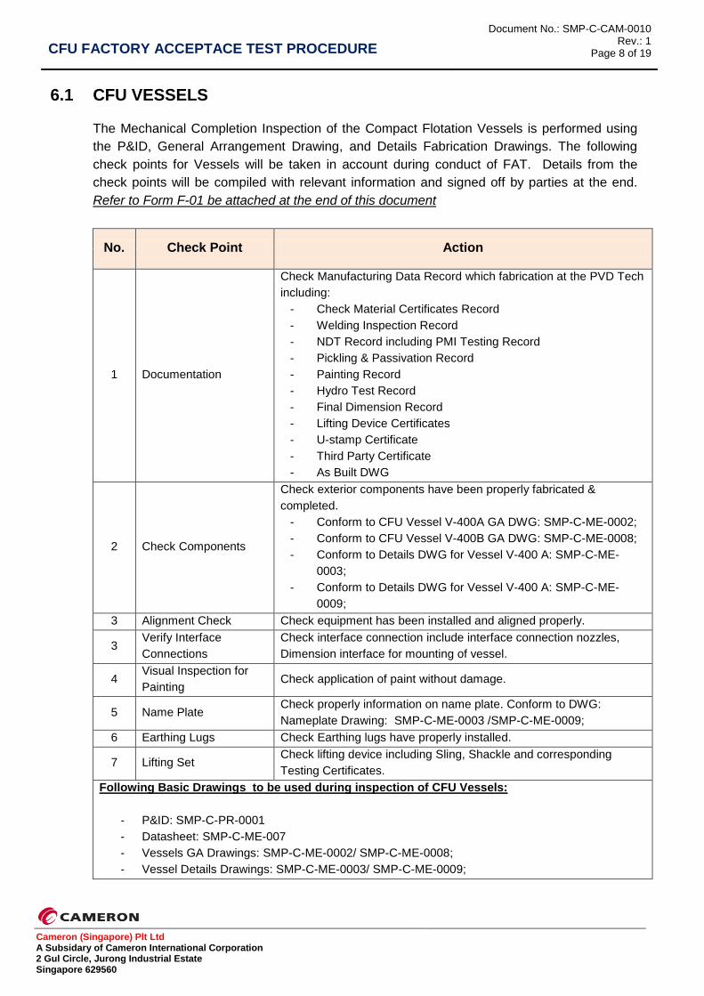
6.1 CFU VESSELS
The Mechanical Completion Inspection of the Compact Flotation Vessels is performed using
the P&ID, General Arrangement Drawing, and Details Fabrication Drawings. The following
check points for Vessels will be taken in account during conduct of FAT. Details from the
check points will be compiled with relevant information and signed off by parties at the end.
Refer to Form F-01 be attached at the end of this document
No. Check Point Action
1
Documentation
Check Manufacturing Data Record which fabrication at the PVD Tech
including:
- Check Material Certificates Record
- Welding Inspection Record
- NDT Record including PMI Testing Record
- Pickling & Passivation Record
- Painting Record
- Hydro Test Record
- Final Dimension Record
- Lifting Device Certificates
- U-stamp Certificate
- Third Party Certificate
- As Built DWG
2 Check Components
Check exterior components have been properly fabricated &
completed.
- Conform to CFU Vessel V-400A GA DWG: SMP-C-ME-0002;
- Conform to CFU Vessel V-400B GA DWG: SMP-C-ME-0008;
- Conform to Details DWG for Vessel V-400 A: SMP-C-ME-
0003;
- Conform to Details DWG for Vessel V-400 A: SMP-C-ME-
0009;
3 Alignment Check Check equipment has been installed and aligned properly.
3 Verify Interface
Connections
Check interface connection include interface connection nozzles,
Dimension interface for mounting of vessel.
4 Visual Inspection for
Painting Check application of paint without damage.
5 Name Plate Check properly information on name plate. Conform to DWG:
Nameplate Drawing: SMP-C-ME-0003 /SMP-C-ME-0009;
6 Earthing Lugs Check Earthing lugs have properly installed.
7 Lifting Set Check lifting device including Sling, Shackle and corresponding
Testing Certificates.
Following Basic Drawings to be used during inspection of CFU Vessels:
- P&ID: SMP-C-PR-0001
- Datasheet: SMP-C-ME-007
- Vessels GA Drawings: SMP-C-ME-0002/ SMP-C-ME-0008;
- Vessel Details Drawings: SMP-C-ME-0003/ SMP-C-ME-0009;
CFU FACTORY ACCEPTACE TEST PROCEDURE
Document No.: SMP-C-CAM-0010 Rev.: 1
Page 9 of 19
Cameron (Singapore) Plt Ltd A Subsidary of Cameron International Corporation 2 Gul Circle, Jurong Industrial Estate Singapore 629560
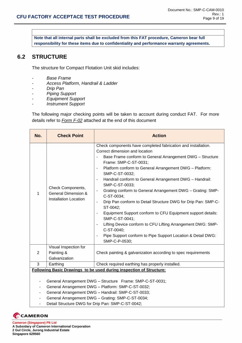
Note that all internal parts shall be excluded from this FAT procedure, Cameron bear full
responsibility for these items due to confidentiality and performance warranty agreements.
6.2 STRUCTURE
The structure for Compact Flotation Unit skid includes: - Base Frame - Access Platform, Handrail & Ladder - Drip Pan - Piping Support - Equipment Support - Instrument Support
The following major checking points will be taken to account during conduct FAT. For more
details refer to Form F-02 attached at the end of this document
No. Check Point Action
1
Check Components,
General Dimension &
Installation Location
Check components have completed fabrication and installation.
Correct dimension and location
- Base Frame conform to General Arrangement DWG – Structure
Frame: SMP-C-ST-0031;
- Platform conform to General Arrangement DWG – Platform:
SMP-C-ST-0032;
- Handrail conform to General Arrangement DWG – Handrail:
SMP-C-ST-0033;
- Grating conform to General Arrangement DWG – Grating: SMP-
C-ST-0034;
- Drip Pan conform to Detail Structure DWG for Drip Pan: SMP-C-
ST-0042;
- Equipment Support conform to CFU Equipment support details:
SMP-C-ST-0041;
- Lifting Device conform to CFU Lifting Arrangement DWG: SMP-
C-ST-0040;
- Pipe Support conform to Pipe Support Location & Detail DWG:
SMP-C-P-0530;
2
Visual Inspection for
Painting &
Galvanization
Check painting & galvanization according to spec requirements
3 Earthing Check required earthing has properly installed.
Following Basic Drawings to be used during inspection of Structure:
- General Arrangement DWG – Structure Frame: SMP-C-ST-0031;
- General Arrangement DWG – Platform: SMP-C-ST-0032;
- General Arrangement DWG – Handrail: SMP-C-ST-0033;
- General Arrangement DWG – Grating: SMP-C-ST-0034;
- Detail Structure DWG for Drip Pan: SMP-C-ST-0042;

CFU FACTORY ACCEPTACE TEST PROCEDURE
Document No.: SMP-C-CAM-0010 Rev.: 1
Page 10 of 19
Cameron (Singapore) Plt Ltd A Subsidary of Cameron International Corporation 2 Gul Circle, Jurong Industrial Estate Singapore 629560
- CFU Equipment support details: SMP-C-ST-0041;
- CFU Lifting Arrangement DWG: SMP-C-ST-0040;
- Pipe Support Location & Detail DWG: SMP-C-P-0530;
6.3 PIPING
In general, the following major check points will be taken in account during conduct FAT for
these connections. For more details refer to Form F-03 attached at the end of this document
No. Test Action
1 Documentation
Check Manufacturing Data Record (Welding Map, Material Inspection Report, Welding Report, NDE Report, Dimensions Check Record, Hydrostatic Test Report, Flushing, Cleaning & Drying Report, Sand Blasting & Painting Report, Leak Test Report, Flange management, Certificate for Valves & Accessories)
2 Check Components
Inspection product to ensure that fabrication & Installation completed C/W DWGs and specification approved.
- Part List Check - Vent - Drain - Support Location - Manual valves installed correctly, tagged and can be
operated freely. - Tag. Name - Flow Code - Blind Ends - Bolt Tightening - Cleaning & Drying - Painting - End closed (if applicable)
3 Installation Location,
Sequence & Alignment
Verify general dimensions, Installation Location, Sequence of
Installation and Alignment including
- Check interface for connection of instrument and Tie-in point.
- Check pipe support installed.
Following Basic Drawings to be used during inspection of Piping
- Piping & Instrumentation Diagram (PID): SPM-C-PR-0001
- Package GA Drawing: SPM-C-ME-001
- Pipe Support Location & Detail DWG: SMP-C-P-0530;
- Piping Isometric DWG: SMP-C-P-0502;
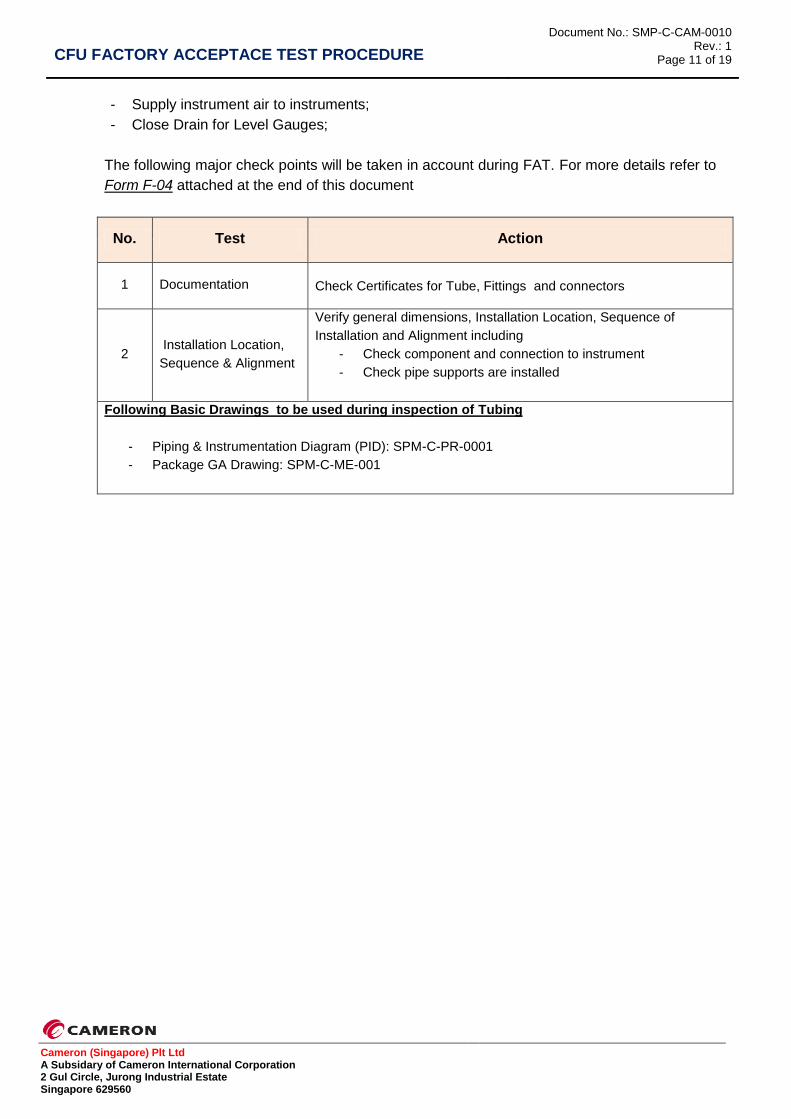
6.4 TUBING
The tubing work includes:
- Sample system;
CFU FACTORY ACCEPTACE TEST PROCEDURE
Document No.: SMP-C-CAM-0010 Rev.: 1
Page 11 of 19
Cameron (Singapore) Plt Ltd A Subsidary of Cameron International Corporation 2 Gul Circle, Jurong Industrial Estate Singapore 629560
- Supply instrument air to instruments;
- Close Drain for Level Gauges;
The following major check points will be taken in account during FAT. For more details refer to
Form F-04 attached at the end of this document
No. Test Action
1 Documentation Check Certificates for Tube, Fittings and connectors
2 Installation Location,
Sequence & Alignment
Verify general dimensions, Installation Location, Sequence of
Installation and Alignment including
- Check component and connection to instrument
- Check pipe supports are installed
Following Basic Drawings to be used during inspection of Tubing
- Piping & Instrumentation Diagram (PID): SPM-C-PR-0001
- Package GA Drawing: SPM-C-ME-001
CFU FACTORY ACCEPTACE TEST PROCEDURE
Document No.: SMP-C-CAM-0010 Rev.: 1
Page 12 of 19
Cameron (Singapore) Plt Ltd A Subsidary of Cameron International Corporation 2 Gul Circle, Jurong Industrial Estate Singapore 629560
PART II - E&I COMPLETION AND TESTING
CFU FACTORY ACCEPTACE TEST PROCEDURE
Document No.: SMP-C-CAM-0010 Rev.: 1
Page 13 of 19
Cameron (Singapore) Plt Ltd A Subsidary of Cameron International Corporation 2 Gul Circle, Jurong Industrial Estate Singapore 629560
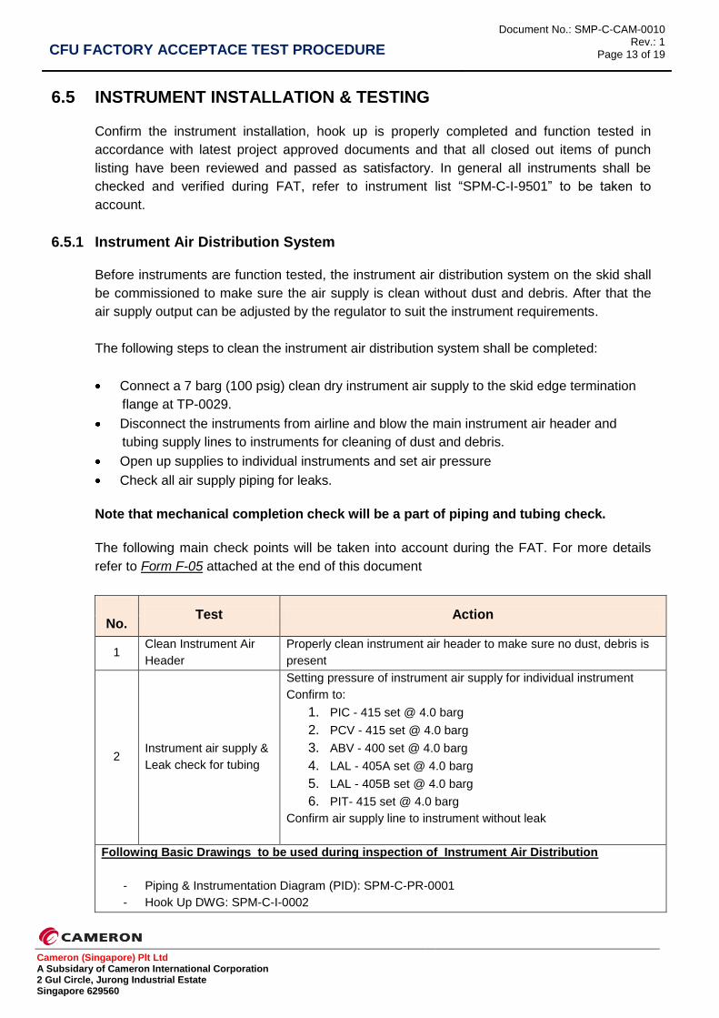
6.5 INSTRUMENT INSTALLATION & TESTING
Confirm the instrument installation, hook up is properly completed and function tested in
accordance with latest project approved documents and that all closed out items of punch
listing have been reviewed and passed as satisfactory. In general all instruments shall be
checked and verified during FAT, refer to instrument list “SPM-C-I-9501” to be taken to
account.
6.5.1 Instrument Air Distribution System
Before instruments are function tested, the instrument air distribution system on the skid shall
be commissioned to make sure the air supply is clean without dust and debris. After that the
air supply output can be adjusted by the regulator to suit the instrument requirements.
The following steps to clean the instrument air distribution system shall be completed:
Connect a 7 barg (100 psig) clean dry instrument air supply to the skid edge termination
flange at TP-0029.
Disconnect the instruments from airline and blow the main instrument air header and
tubing supply lines to instruments for cleaning of dust and debris.
Open up supplies to individual instruments and set air pressure
Check all air supply piping for leaks.
Note that mechanical completion check will be a part of piping and tubing check.
The following main check points will be taken into account during the FAT. For more details
refer to Form F-05 attached at the end of this document
No. Test Action
1 Clean Instrument Air
Header
Properly clean instrument air header to make sure no dust, debris is
present
2 Instrument air supply &
Leak check for tubing
Setting pressure of instrument air supply for individual instrument
Confirm to:
1. PIC - 415 set @ 4.0 barg
2. PCV - 415 set @ 4.0 barg
3. ABV - 400 set @ 4.0 barg
4. LAL - 405A set @ 4.0 barg
5. LAL - 405B set @ 4.0 barg
6. PIT- 415 set @ 4.0 barg
Confirm air supply line to instrument without leak
Following Basic Drawings to be used during inspection of Instrument Air Distribution
- Piping & Instrumentation Diagram (PID): SPM-C-PR-0001
- Hook Up DWG: SPM-C-I-0002
CFU FACTORY ACCEPTACE TEST PROCEDURE
Document No.: SMP-C-CAM-0010 Rev.: 1
Page 14 of 19
Cameron (Singapore) Plt Ltd A Subsidary of Cameron International Corporation 2 Gul Circle, Jurong Industrial Estate Singapore 629560
- Instrument Datasheets
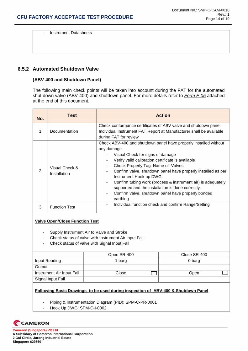
6.5.2 Automated Shutdown Valve (ABV-400 and Shutdown Panel) The following main check points will be taken into account during the FAT for the automated shut down valve (ABV-400) and shutdown panel. For more details refer to Form F-05 attached at the end of this document.
No. Test Action
1 Documentation
Check conformance certificates of ABV valve and shutdown panel
Individual Instrument FAT Report at Manufacturer shall be available
during FAT for review
2 Visual Check &
Installation
Check ABV-400 and shutdown panel have properly installed without
any damage.
- Visual Check for signs of damage
- Verify valid calibration certificate is available
- Check Properly Tag. Name of Valves
- Confirm valve, shutdown panel have properly installed as per
Instrument Hook up DWG.
- Confirm tubing work (process & instrument air) is adequately
supported and the installation is done correctly.
- Confirm valve, shutdown panel have properly bonded
earthing
3 Function Test - Individual function check and confirm Range/Setting
Valve Open/Close Function Test
- Supply Instrument Air to Valve and Stroke
- Check status of valve with Instrument Air Input Fail
- Check status of valve with Signal Input Fail
Open SR-400 Close SR-400
Input Reading 1 barg 0 barg
Output
Instrument Air Input Fail Close Open
Signal Input Fail
Following Basic Drawings to be used during inspection of ABV-400 & Shutdown Panel
- Piping & Instrumentation Diagram (PID): SPM-C-PR-0001
- Hook Up DWG: SPM-C-I-0002
CFU FACTORY ACCEPTACE TEST PROCEDURE
Document No.: SMP-C-CAM-0010 Rev.: 1
Page 15 of 19
Cameron (Singapore) Plt Ltd A Subsidary of Cameron International Corporation 2 Gul Circle, Jurong Industrial Estate Singapore 629560
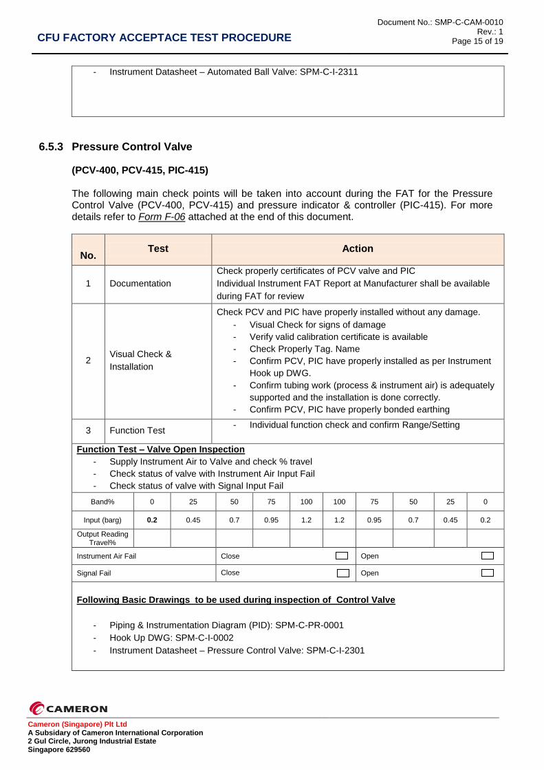
- Instrument Datasheet – Automated Ball Valve: SPM-C-I-2311
6.5.3 Pressure Control Valve (PCV-400, PCV-415, PIC-415) The following main check points will be taken into account during the FAT for the Pressure Control Valve (PCV-400, PCV-415) and pressure indicator & controller (PIC-415). For more details refer to Form F-06 attached at the end of this document.
No. Test Action
1 Documentation
Check properly certificates of PCV valve and PIC
Individual Instrument FAT Report at Manufacturer shall be available
during FAT for review
2 Visual Check &
Installation
Check PCV and PIC have properly installed without any damage.
- Visual Check for signs of damage
- Verify valid calibration certificate is available
- Check Properly Tag. Name
- Confirm PCV, PIC have properly installed as per Instrument
Hook up DWG.
- Confirm tubing work (process & instrument air) is adequately
supported and the installation is done correctly.
- Confirm PCV, PIC have properly bonded earthing
3 Function Test - Individual function check and confirm Range/Setting
Function Test – Valve Open Inspection
- Supply Instrument Air to Valve and check % travel
- Check status of valve with Instrument Air Input Fail
- Check status of valve with Signal Input Fail
Band% 0 25 50 75 100 100 75 50 25 0
Input (barg) 0.2 0.45 0.7 0.95 1.2 1.2 0.95 0.7 0.45 0.2
Output Reading Travel%
Instrument Air Fail Close Open
Signal Fail Close Open
Following Basic Drawings to be used during inspection of Control Valve
- Piping & Instrumentation Diagram (PID): SPM-C-PR-0001
- Hook Up DWG: SPM-C-I-0002
- Instrument Datasheet – Pressure Control Valve: SPM-C-I-2301

CFU FACTORY ACCEPTACE TEST PROCEDURE
Document No.: SMP-C-CAM-0010 Rev.: 1
Page 16 of 19
Cameron (Singapore) Plt Ltd A Subsidary of Cameron International Corporation 2 Gul Circle, Jurong Industrial Estate Singapore 629560
6.5.4 Pressure Transmitter
(PT- 401, PT- 415) The following check points will be taken into account during the FAT for the Pressure Transmitter (PT- 401, PT- 415). For more details refer to Form F-07 attached at the end of this document.
No. Test Action
1 Documentation
Check properly certificates of Pressure Transmitters
Individual Instrument FAT Report at Manufacturer shall be available
during FAT for review
2 Visual Check &
Installation
Check Pressure Transmitters have properly installed without any
damage.
- Visual Check for signs of damage
- Verify valid calibration certificate is available
- Check Properly Tag. Name
- Confirm Pressure Transmitters have properly installed as per
Instrument Hook up DWG.
- Confirm tubing work (process & instrument air) is adequately
supported and the installation is done correctly.
- Confirm Pressure Transmitters have properly bonded
earthing
Following Basic Drawings to be used during inspection of Pressure Transmitters
- Piping & Instrumentation Diagram (PID): SPM-C-PR-0001
- Hook Up DWG: SPM-C-I-0002
- Instrument Datasheet – Pressure Transmitters: SPM-C-I-2303
6.5.5 Flow Indicator (FI- 401A/B, FI- 402A/B, FI- 403A/B, FI- 404A/B, FI-413) The following check points will be taken into account during the FAT for Flow Indicators. For more details refer to Form F-08 attached at the end of this document.
No. Test Action
1 Documentation
Check properly certificates of Flow Indicators
Individual Instrument FAT Report at Manufacturer shall be available
during FAT for review
2 Visual Check &
Installation
Check Flow Indicators have properly installed without any damage.
- Visual Check for signs of damage
- Verify valid calibration certificate is available
- Verify measurement range
- Check Properly Tag. Name
CFU FACTORY ACCEPTACE TEST PROCEDURE
Document No.: SMP-C-CAM-0010 Rev.: 1
Page 17 of 19
Cameron (Singapore) Plt Ltd A Subsidary of Cameron International Corporation 2 Gul Circle, Jurong Industrial Estate Singapore 629560
- Confirm Flow Indicator have properly installed as per
Instrument Hook up DWG.
Following Basic Drawings to be used during inspection of Flow Indicator
- Piping & Instrumentation Diagram (PID): SPM-C-PR-0001
- Hook Up DWG: SPM-C-I-0002
- Instrument Datasheet – Flow Gauge Rotameter: SPM-C-I-2306
- Instrument Datasheet – Orifice dP Type Flow Gauge: SPM-C-I-2313
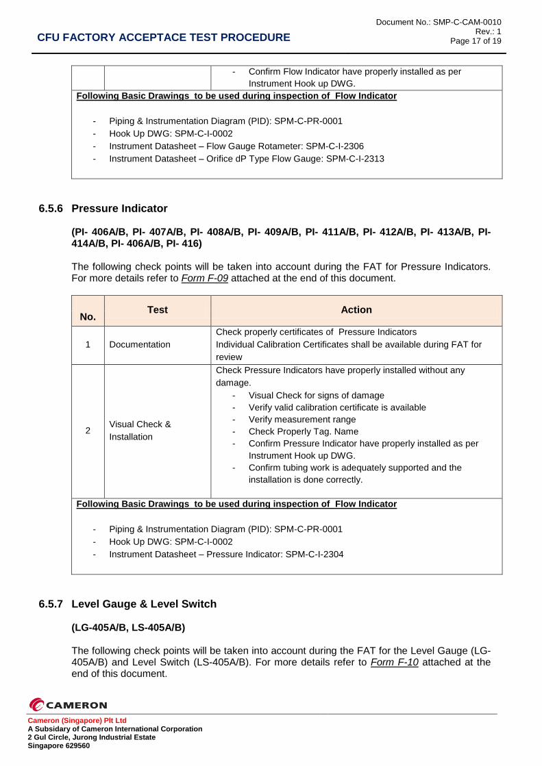
6.5.6 Pressure Indicator
(PI- 406A/B, PI- 407A/B, PI- 408A/B, PI- 409A/B, PI- 411A/B, PI- 412A/B, PI- 413A/B, PI- 414A/B, PI- 406A/B, PI- 416) The following check points will be taken into account during the FAT for Pressure Indicators. For more details refer to Form F-09 attached at the end of this document.
No. Test Action
1 Documentation
Check properly certificates of Pressure Indicators
Individual Calibration Certificates shall be available during FAT for
review
2 Visual Check &
Installation
Check Pressure Indicators have properly installed without any
damage.
- Visual Check for signs of damage
- Verify valid calibration certificate is available
- Verify measurement range
- Check Properly Tag. Name
- Confirm Pressure Indicator have properly installed as per
Instrument Hook up DWG.
- Confirm tubing work is adequately supported and the
installation is done correctly.
Following Basic Drawings to be used during inspection of Flow Indicator
- Piping & Instrumentation Diagram (PID): SPM-C-PR-0001
- Hook Up DWG: SPM-C-I-0002
- Instrument Datasheet – Pressure Indicator: SPM-C-I-2304
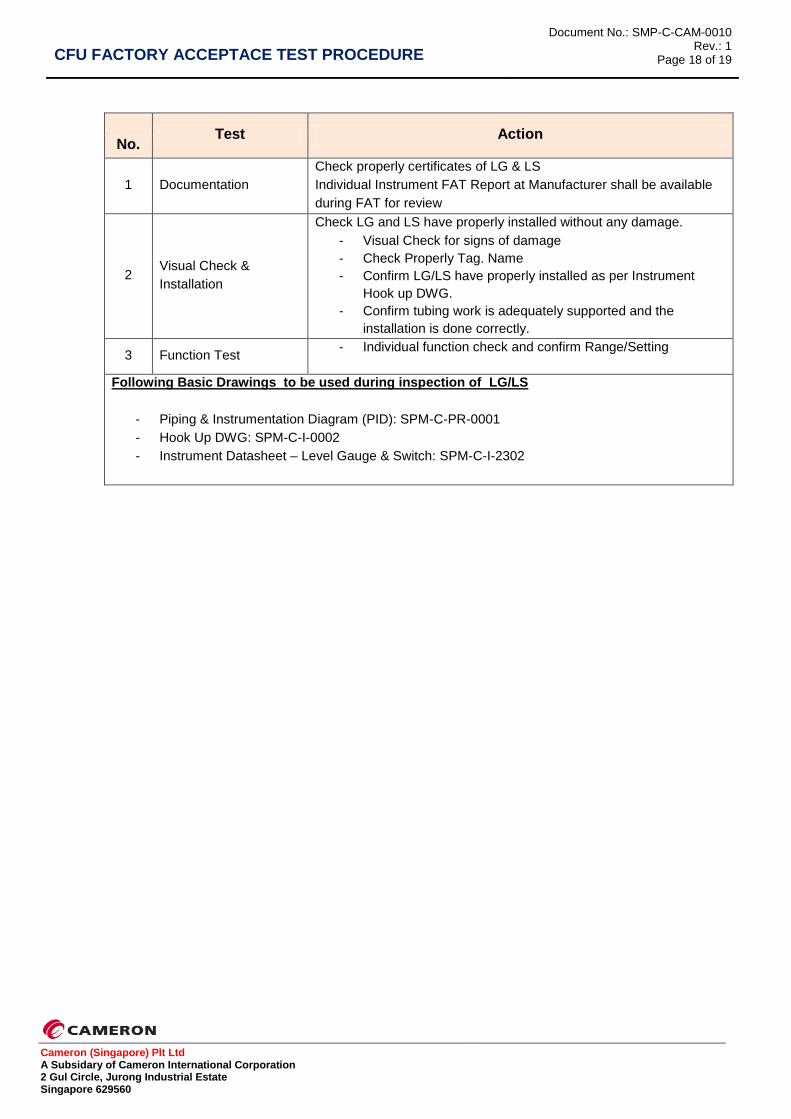
6.5.7 Level Gauge & Level Switch
(LG-405A/B, LS-405A/B) The following check points will be taken into account during the FAT for the Level Gauge (LG-405A/B) and Level Switch (LS-405A/B). For more details refer to Form F-10 attached at the end of this document.
CFU FACTORY ACCEPTACE TEST PROCEDURE
Document No.: SMP-C-CAM-0010 Rev.: 1
Page 18 of 19
Cameron (Singapore) Plt Ltd A Subsidary of Cameron International Corporation 2 Gul Circle, Jurong Industrial Estate Singapore 629560
No. Test Action
1 Documentation
Check properly certificates of LG & LS
Individual Instrument FAT Report at Manufacturer shall be available
during FAT for review
2 Visual Check &
Installation
Check LG and LS have properly installed without any damage.
- Visual Check for signs of damage
- Check Properly Tag. Name
- Confirm LG/LS have properly installed as per Instrument
Hook up DWG.
- Confirm tubing work is adequately supported and the
installation is done correctly.
3 Function Test - Individual function check and confirm Range/Setting
Following Basic Drawings to be used during inspection of LG/LS
- Piping & Instrumentation Diagram (PID): SPM-C-PR-0001
- Hook Up DWG: SPM-C-I-0002
- Instrument Datasheet – Level Gauge & Switch: SPM-C-I-2302
CFU FACTORY ACCEPTACE TEST PROCEDURE
Document No.: SMP-C-CAM-0010 Rev.: 1
Page 19 of 19
Cameron (Singapore) Plt Ltd A Subsidary of Cameron International Corporation 2 Gul Circle, Jurong Industrial Estate Singapore 629560
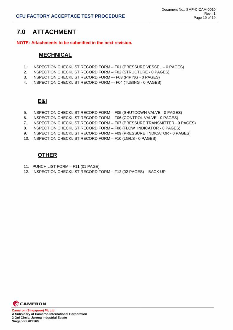
7.0 ATTACHMENT
NOTE: Attachments to be submitted in the next revision.
MECHNICAL
1. INSPECTION CHECKLIST RECORD FORM – F01 (PRESSURE VESSEL – 0 PAGES)
2. INSPECTION CHECKLIST RECORD FORM – F02 (STRUCTURE - 0 PAGES)
3. INSPECTION CHECKLIST RECORD FORM –- F03 (PIPING - 0 PAGES)
4. INSPECTION CHECKLIST RECORD FORM –- F04 (TUBING - 0 PAGES)
E&I
5. INSPECTION CHECKLIST RECORD FORM – F05 (SHUTDOWN VALVE - 0 PAGES)
6. INSPECTION CHECKLIST RECORD FORM – F06 (CONTROL VALVE - 0 PAGES)
7. INSPECTION CHECKLIST RECORD FORM – F07 (PRESSURE TRANSMITTER - 0 PAGES)
8. INSPECTION CHECKLIST RECORD FORM – F08 (FLOW INDICATOR - 0 PAGES)
9. INSPECTION CHECKLIST RECORD FORM – F09 (PRESSURE INDICATOR - 0 PAGES)
10. INSPECTION CHECKLIST RECORD FORM – F10 (LG/LS - 0 PAGES)
OTHER
11. PUNCH LIST FORM – F11 (01 PAGE)
12. INSPECTION CHECKLIST RECORD FORM – F12 (02 PAGES) – BACK UP