
Simplified Root Architectural Models Using Continuous Deformable Domains
Upload
independentCategory
view
2download
0
A Topology Preserving Level Set Method forGeometric Deformable Models
Xiao Han, Student Member, IEEE, Chenyang Xu, Member, IEEE, and
Jerry L. Prince, Senior Member, IEEE
Abstract—Active contour and surface models, also known as deformable models, are powerful image segmentation techniques.
Geometric deformable models implemented using level set methods have advantages over parametric models due to their intrinsic
behavior, parameterization independence, and ease of implementation. However, a long claimed advantage of geometric deformable
models—the ability to automatically handle topology changes—turns out to be a liability in applications where the object to be
segmented has a known topology that must be preserved. In this paper, we present a new class of geometric deformable models
designed using a novel topology-preserving level set method, which achieves topology preservation by applying the simple point
concept from digital topology. These new models maintain the other advantages of standard geometric deformable models including
subpixel accuracy and production of nonintersecting curves or surfaces. Moreover, since the topology-preserving constraint is
enforced efficiently through local computations, the resulting algorithm incurs only nominal computational overhead over standard
geometric deformable models. Several experiments on simulated and real data are provided to demonstrate the performance of this
new deformable model algorithm.
Index Terms—Geometric deformable model, topology preservation, topological constraint, level set method, digital topology, simple
points, active contours.
æ
1 INTRODUCTION
DEFORMABLE models are object-delineating curves orsurfaces that move within two-dimensional (2D) or
three-dimensional (3D) digital images under the influence ofboth internal and external forces and user defined con-straints. Since their introduction by Kass et al. [1], thesealgorithms have been at the heart of one of the most active andsuccessful research areas in edge detection, image segmenta-tion, shape modeling, and visual tracking. Deformablemodels are broadly classified as either parametric deformablemodels (see [1], [2], [3], [4], [5]) or geometric deformable models(see [6], [7], [8], [9], [10], [11], [12], [13], [14], [15], [16])according to their representation and implementation. Inparticular, parametric deformable models are representedexplicitly as parameterized contours1 (i.e., curves or surfaces)in a Lagrangian framework. They are the older of the twoformulations and have been extensively used in manyapplications (see [17], for example). Geometric deformablemodels, on the other hand, are represented implicitly as levelsets of higher-dimensional, scalar level set functions andevolve in an Eulerian fashion [18]. Geometric deformable
models were introduced more recently by Caselles et al. [6]and by Malladi et al. [7].
Geometric deformable models have several importantadvantages over parametric models. First, they are com-pletely intrinsic and, therefore, are independent of theparameterization of the evolving contour. In fact, the modelis generally not parameterized until evolution of the levelset function is complete. Thus, there is no need to add orremove nodes from an initial parameterization or adjust thespacing of the nodes as in parametric models. Second, theintrinsic geometric properties of the contour, such as theunit normal vector and the curvature, can be easilycomputed from the level set function. This contrasts withthe parametric case, where inaccuracies in the calculationsof normals and curvature result from the discrete nature ofthe contour parameterization. Third, the propagatingcontour can automatically change topology in geometricmodels (e.g., merge or split) without requiring an elaboratemechanism to handle such changes as in parametric models(see [19], [20]). Finally, the resulting contours do not containself-intersections, which are computationally costly toprevent in parametric deformable models (see [21]).
Topological flexibility has long been claimed as a majoradvantage of geometric deformable models over parametricdeformable models. Such flexibility is so desirable in someapplications that methods to adaptively change the contourtopology have also been developed for parametric deform-able models [19], [20]. But, topological flexibility is not alwaysdesired. In particular, when a specific object (target) is soughtand its composition—i.e., the number of components and thehomology of each component—is known, then it is mostnatural to seek the target in a way that yields the correctcomposition or topology. For example, in the analysis of3D brain images—the application that motivated our work onthis subject—it is desirable that a reconstruction of the cortical
IEEE TRANSACTIONS ON PATTERN ANALYSIS AND MACHINE INTELLIGENCE, VOL. 25, NO. 6, JUNE 2003 755
. X. Han and J.L. Prince are with the Electrical and Computer EngineeringDepartment, Johns Hopkins University, 105 Barton Hall, 3400 NorthCharles Street, Baltimore, MD 21218. E-mail: {xhan, prince}@jhu.edu.
. C. Xu is with the Imaging and Visualization Department, SiemensCorporate Research, Inc., 755 College Road East, Princeton, NJ 08501.E-mail: [email protected].
Manuscript received 13 May 2002; revised 14 Nov. 2002; accepted 20 Nov.2002.Recommended for acceptance by Y. Amit.For information on obtaining reprints of this article, please send e-mail to:[email protected], and reference IEEECS Log Number 116535.
1. In this paper, we use the word contour to refer to either a curve orsurface, and the words curve and surface are used explicitly only when thedimensionality must be clear.
0162-8828/03/$17.00 ß 2003 IEEE Published by the IEEE Computer Society

surface have a topology that is consistent with brain anatomy[22], [21]. Recently, in fact, there have been several post-processing methods reported to correct the topology of acortical segmentation that has the wrong topology [23], [24],[25]. In this application, and others like it, the topologyflexibility of geometric deformable models is considered to bea liability rather than an advantage [25].
When topology preservation is desired, parametricdeformable models are typically used because topology isexplicitly maintained by their Lagrangian formulation. Self-intersections can become a problem in these algorithms,however, when external forces drive the model verticestogether and step sizes are simultaneously selected to belarge in order to reduce convergence time. When simplecontours are required—as is usually the case in imagesegmentation—some additional computations are necessaryin order to avoid self-intersections. Unfortunately, thecomputational demands related to self-intersection detec-tion are very high, especially for surfaces [21], and mostparametric models neglect this step, relying on smoothexternal forces and extremely small step sizes instead.Geometric deformable models inherently prevent self-intersections because of the level set representation as wellas the entropy conditions imposed during level setevolution [26], [18] and the way isocontours are typicallycomputed (see [27]). But, prior to this paper, there has beenno way to take advantage of this property (and the othernice properties of geometric deformable models) and toprevent topological changes during the level set evolution.The difficulty of developing a level set method thatpreserves topology has been noted by Hermosillo et al.[28]. They speak of the need for a topology-preservingevolution and then comment “[f]or planar curves, such anevolution is given by the curvature flow, but unfortunatelythis is not the case for surfaces. Much research has beendevoted to this problem, but it remains an open one.”
In this paper, we develop a topology-preserving level setmethod (TLSM) for geometric deformable models thatguarantees that the final contour has exactly the sametopology as the initial one and does not contain any self-intersection. Topology preservation is achieved by main-taining the topology of the digital object enclosed by theimplicit contour, for which we make use of the simple pointcriterion from digital topology [29], [30], [31]. We note thatour approach maintains the subpixel interpolation andboundary regularization properties of geometric deform-able models, which distinguishes our method from thetopology-preserving region growing method of Mangin etal. [32]. The TLSM we describe can be used with anyexisting 2D or 3D geometric deformable model, regardlessof the internal or external force definition, yielding a largenew class of deformable models, which we will refer to astopology-preserving geometric deformable models (TGDM’s).2
The remainder of the paper is organized as follows: InSection 2, we present the basic notation and key ideas of thegeometric deformable models. We then present our topology-preserving framework in Section 3. Experimental results onboth 2D and 3D phantoms and real data are shown in Section 4to demonstrate the behavior and advantages of the newTGDM’s, which also serve as an illustration for their potentialapplications. Section 5 summarizes the method, discusses the
results, and gives more details on the connections betweenprevious work and our approach. Finally, we give a briefconclusion in Section 6.
We note that preliminary results related to this workhave been described in a conference paper [34] and itsapplication to brain cortex segmentation has been describedin [35], [36].
2 GEOMETRIC DEFORMABLE MODELS
Geometric deformable models are based on the theory of frontevolution and are implemented using the level set numericalmethod [18]. In this section, we briefly review the main theoryand major results of geometric deformable models.
2.1 Front Evolution and Level Set Theory
Let Cðp; tÞ, defined as fxðp; tÞ; yðp; tÞg in 2D andfxðp; tÞ; yðp; tÞ; zðp; tÞg in 3D, denote a family of closedcontours (i.e., curves or surfaces) generated by evolvingan initial contour C0ðpÞ ¼ Cðp; 0Þ, where t parameterizesthe family and p parameterizes the given contour. Thebasic result from the front evolution theory is that thegeometric shape of the contour is determined by thenormal component of the evolution velocity, while thetangential component affects only the parameterization.Hence, after a possible reparameterization, the evolutionequation can be written as
@Cðp;tÞ@t ¼ F ðCðp; tÞÞ~nnðCðp; tÞÞ;
Cðp; 0Þ ¼ C0ðpÞ;
�ð1Þ
where F ðCðp; tÞÞ is a scalar function that often depends onthe curvature � of the contour (for surfaces, both mean andGaussian curvatures can be used), and ~nnðCðp; tÞÞ is the unitnormal vector (conventionally chosen to be the inwardnormal) along the contour Cðp; tÞ.
The Lagrangian approach to the above evolution equationinvolves discretizing the contour into a set of elements (e.g.,nodes connected by lines or triangles) and updating the nodepositions using a numerical approximation to (1). This is theapproach of parametric deformable models. Frequent adjust-ment of the node spacing is required in order to preserve datafidelity and reduce numerical approximation errors. Com-putationally complex approaches may also be required forself-intersection avoidance.
The level set technique developed by Osher and Sethian[26] represents the contour Cðp; tÞ implicitly as the zerolevel set of a smooth, Lipschitz-continuous scalar function�ðx; tÞ, also known as the level set function, where x 2 R2 in2D and x 2 R3 in 3D. The implicit contour at any time t isgiven by Cð�; tÞ ¼ fxj�ðx; tÞ ¼ 0g. Although there areinfinite many choices of the level set function, in practice,the signed distance function is preferred for its stability innumerical computations. The fast marching method pro-posed in [37], [38] provides an efficient algorithm forconstructing the signed distance function from a giveninitial contour. We used signed distance functions con-structed in this way for all of our experiments in this paper.
By differentiating �ðx; tÞ ¼ 0 with respect to t andsubstituting (1), the following associated equation of motionfor the level set function �ðx; tÞ can be derived:
@�ðx;tÞ@t ¼ F ðx; tÞjr�ðx; tÞj;
�ðC0ðpÞ; 0Þ ¼ 0;
�ð2Þ
756 IEEE TRANSACTIONS ON PATTERN ANALYSIS AND MACHINE INTELLIGENCE, VOL. 25, NO. 6, JUNE 2003
2. The GDM acronym used here does not mean geometrically deformablemodels, which is a different concept introduced by J. Miller et al. [33] andshares the same acronym.

where r is the gradient operator and jr�j denotes thenorm of the gradient of �. Note that the function F ðx; tÞ isonly defined at the contour location originally and, hence,needs to be extended to the whole computational domain(see [18]) in order that (2) applies to the whole space.
2.2 Geometric Deformable Models
Caselles et al. [6] and Malladi et al. [7] applied the abovetheory to the problem of image segmentation by multi-plying the contour velocity by a “stopping” term gðjrIðxÞjÞthat is a monotonically decreasing function of the gradientmagnitude of the image I (or its smoothed version). In thisway, they arrived at the following evolution equation
@�ðx; tÞ@t
¼ gðjrIðxÞjÞðcþ �ðx; tÞÞjr�ðx; tÞj; ð3Þ
where c is a constant inflation or deflation (depending on itssign) speed term that aims to keep the contour moving inthe proper direction, and �ðx; tÞ is the (mean) curvature ofthe level set of �ð�; tÞ that passes through the point x, whichcan be easily computed from the spatial derivatives of �ð�; tÞ(see [18]). We note that, in [6], [7], the above formulation isoriginally derived for planar curves, however, the verysame form applies to surfaces as well. In the remainder ofthis paper, all of the equations apply to both curves andsurfaces unless stated otherwise.
The model of (3) does not arise from the minimization ofan energy functional as in the classical active contourmodels. To address this, Caselles et al. [8], [9] andKichenassamy et al. [10], [11] derived another geometricdeformable model, called the geodesic active contour model.The basic idea is to consider the object boundary detectionas a problem of geodesic computation in a Riemannianspace, according to a metric gðxÞ induced by the givenimage I. This idea can be formally written as
minCJðCÞ ¼
ZgðCðpÞÞdC; ð4Þ
where dC denotes the arc-length in 2D or the infinitesimalarea element in 3D, and gðxÞ is usually chosen to be the sameas the stopping term gðjrIðxÞjÞ used in the previous model.
Minimizing JðCÞ using a steepest descent algorithm
starting from an initial contour C0 gives the following
contour evolution equation
@Cðp;tÞ@t ¼ðgðCðp;tÞÞ�ðCðp;tÞÞÿrgðCðp;tÞÞ�~nnðCðp;tÞÞÞ~nnðCðp;tÞÞ;
Cðp; 0Þ ¼ C0ðpÞ:
�ð5Þ
This geodesic active contour model can be readily castwithin the level set framework. This yields an equivalentcontour evolution process implemented using the followinglevel set function evolution equation
@�ðx; tÞ@t
¼ gðxÞjr�ðx; tÞjdivr�ðx; tÞjr�ðx; tÞj
� �þrgðxÞ � r�ðx; tÞ
¼ gðxÞ�ðx; tÞjr�ðx; tÞj þ rgðxÞ � r�ðx; tÞ;ð6Þ
where divð�Þ denotes the divergence of its argument, and�ðx; tÞ is the (mean) curvature as in (3).
There are many other extensions of the basic geometricdeformable model in the literature (e.g., [13], [39], [40], [14],
[41], [15], [16]) which were designed either to improve theoverall performance of the original model or to adapt toparticular applications. In this work, we consider a verygeneral framework summarized by the following evolutionequation [18], [41]:
@�ðx; tÞ@t
¼ Fpropðx; tÞjr�ðx; tÞj þ Fcurvðx; tÞjr�ðx; tÞj
þ ~FF advðx; tÞ � r�ðx; tÞ;ð7Þ
where Fpropðx; tÞjr�ðx; tÞj is an expansion or contractionforce or speed (people use “force” and “speed” inter-changeably); Fcurvðx; tÞjr�ðx; tÞj is the part of the force thatdepends on the intrinsic geometry, especially the (mean)curvature �ðx; tÞ; and ~FF advðx; tÞ � r�ðx; tÞ is an advectionforce that passively transports the contour.
The right-hand side of (7) can arise from the gradientdescent minimization of an energy functional as in thegeodesic active contour model (6), where Fpropðx; tÞ ¼ 0,Fcurvðx; tÞ ¼ �ðx; tÞgðxÞ, and ~FF advðx; tÞ ¼ rgðxÞ. In general,however, one can choose a different form for each forceterm for a given purpose. As an example, we can chooseFpropðx; tÞ ¼ RðxÞ to be a region force3 (see [15], [41]) or abinary flow force [14], Fcurvðx; tÞ to be proportional to the(mean) curvature �ðx; tÞ, and ~FF advðx; tÞ ¼ ~vvðxÞ to be agradient vector flow force [4]. With these choices theevolution equation becomes
@�ðx; tÞ@t
¼ !RRðxÞjr�ðx; tÞj þ !��ðx; tÞjr�ðx; tÞj
þ !~vv~vvðxÞ � r�ðx; tÞ;ð8Þ
where !R, !�, and !~vv are weights for the respective forces.For a binary-valued image I having values zero or one, it isconvenient to define RðxÞ ¼ 2IðxÞ ÿ 1 to provide anexpansion force inside the object and a contraction forceoutside. The model in (8) is used in the 3D experimentspresented later in this paper.
2.3 Numerical Implementation
One advantage of the geometric deformable model is that,even though the implicit contour itself can developsingularities (like cusps and corners) and can merge orsplit to change topology, the level set function � remainswell-defined. Thus, one can discretize the level set evolu-tion equation on a fixed Cartesian grid and use a finitedifference scheme to robustly solve the evolution equationnumerically. In order to capture the singularities that mightdevelop along the implicit contour, Osher and Sethian [26]proposed an upwind scheme that incorporates piecewisecontinuous approximations to � and utilizes one-sided (orupwind) derivatives in the approximation of r�. Thescheme is numerically stable and produces an entropy-satisfying viscosity solution to (7).
Denote a grid point by xi and the discrete time scale bytm, where i;m are integers. The resulting level set updateequation can be written as
�ðxi; tmþ1Þ ¼ �ðxi; tmÞ þ�t��ðxi; tmÞ; ð9Þ
where �t ¼ tmþ1 ÿ tm is the time-step size. Since we areinterested in a generic geometric deformable model, we use�� to denote the upwind finite difference approximation to
HAN ET AL.: A TOPOLOGY PRESERVING LEVEL SET METHOD FOR GEOMETRIC DEFORMABLE MODELS 757
3. Also known as a signed pressure force.
the right-hand side of (7) (see [18] for an explicit formula).Given an initial level set function �ð�; t0Þ, (9) can be used toupdate the level set function at successive time instantstmþ1;m ¼ 0; 1; . . . ; until convergence. Although not expli-citly computed until the end, the zero level set of �ð�; tmÞ,m ¼ 1; 2; . . . represents the evolving contour(s).
As mentioned before, the forces are really only meaningfulat the moving contour itself, i.e., the zero level set of �. Yet, theupdate equation (9) applies to all values of �, not just thosearound zero. In fact, it is clear from (6) that, in thisimplementation of the geodesic deformable model, the forceshave been “naturally” extended to apply to all level sets, notjust the zero level set. By “naturally,” it is meant that the sameexpression is used to evaluate the forces over the wholecomputational domain. One implication of this particularforce extension is that all level sets are attracted to the desiredimage feature, which tends to crowd the level sets closertogether as the iterations proceed. Because of this, periodicreinitialization of the level set function (using the fastmarching method, for example) is required in order that itclosely approximates a signed distance function; this im-proves numerical stability and accuracy of the overallcomputation. An alternate extension method that preserves� at any time as a signed distance function was presented in[42], [18],but thisrequires morecomputation per iterationandis generally much slower than this simple periodic reinitia-lization scheme.
There are several ways to increase the computationalspeed of geometric deformable models including time-implicit numerical schemes and the narrow band method.In time-implicit numerical schemes [43], [44], the level setfunction at the current time step is updated from itsprevious values by solving a system of linear equations,which means that the level set function at the grid pointsare updated all at once. Time-implicit schemes, however,are not compatible with the topology-preserving mechan-ism that we describe herein, since they do not permit pointsto be controlled individually. We require a time-explicitstep in order to be able to maintain explicit control oftopology at each iteration. The narrow band method [45],[46] is perfectly compatible with our methods and, in fact,provides a considerable computational advantage sinceonly a small set of grid points near the zero level set aremodified during each iteration. Furthermore, our methodcan be expressed as a small, but critically importantmodification to the standard narrow band method. For thisreason, we now give the explicit steps of the narrow bandimplementation of a geometric deformable model.
Algorithm 1: Narrow Band Algorithm1. Initialize—Set m ¼ 0 and t0 ¼ 0. Initialize �ð�; 0Þ to be the
signed distance function of the initial contour.2. Build the Narrow Band—Find the narrow band points.
These are the grid points xi whose distance j�ðxi; tmÞj isless than the specified narrow band width.
3. Update—Set tmþ1 ¼ tm þ�t. For every narrow band pointxi, update its level set function value �ðxi; tmþ1Þ using(9).
4. Reinitialize—If necessary, reinitialize �ð�; tmþ1Þ to be thesigned distance function of its own zero level set.
5. Convergence Test—Check whether the iterations haveconverged. If yes, stop; otherwise set m ¼ mþ 1. Ifreinitialization was performed in Step 4, then go to Step 2to rebuild the narrow band; otherwise, go to Step 3.
It is worth making a few comments about the narrow bandmethod. First, we note that in Step 3, the narrow band pointscan be processed in an arbitrary order since each point isupdated using function values from the previous time-step.Second, reinitialization of the level set function is periodicallyrequired not only to prevent “bunching” as described above,but also to prevent the zero level set from moving out of thecurrent narrow band (see [18]). Third, the topology of theembedded contour is normally free to change in an arbitraryfashion during the evolution of �. This means that thetopology of the final contour is ordinarily unpredictable;images with clutter or noise can very easily produceunexpected topological results involving multiple objects,nested objects, or handles (which are found only on surfaces).
3 TOPOLOGY-PRESERVING LEVEL SET METHOD
In this section, we describe a mechanism to preserve thetopology of one or multiple implicit contours during theevolutionof theembeddinglevelset function.Westartwithanoverview of the basic principles underlying this work,especially the digital embedding of the implicit contourtopology. We then review the fundamental concepts andnotation from digital topology and introduce the definitionand computation of “simple” points. We also present ourtopology-preserving narrow band algorithm. To betterunderstand the convergence properties of this algorithm, wethen present an interpretation of this algorithm as aconstrained gradient descent algorithm in the special case ofthe geodesic deformable model. We then introduce 2D and 3Dconnectivity consistent isocontour algorithms that are guar-anteed to produce topologically correct explicit representa-tion of the implicit contour embedded in a level set function.
3.1 Overview of Basic Principles
Digital Embedding of Topology. Although geometricdeformable models are formulated on the continuum, inpractice they are always implemented on a digital domain—i.e., on a lattice of grid points connected by grid cells orvoxels. Without restrictions on their functional form, there are,in general, an infinite number of contours having the samesampled level set function. Since these contours can havedifferent numbers of components with different topologies, itis clear that it is generally impossible to recover the “true”topology of an arbitrary implicit contour from samples of itslevel set function. Therefore, in order to give meaning to theidea of “preserving topology” in a geometric deformablemodel, we must adopt certain conventions about the nature ofthe implied contour given its sampled level set function. Theconvention we describe below addresses the following twobroad ambiguities. First, a continuous implicit contour mightbe entirely contained in one voxel or it might intersect a voxelboundary any number of times. These phenomena basicallydescribe types of high frequency behavior not captured by thedigital samples. Second, even if the contour is slowly varying,there might still be ambiguities as to how a cell is actuallypartitioned by a contour (see Section 3.4 and the figurestherein). This ambiguity is directly tied to the classicalproblems of ambiguous voxels and faces in isocontouralgorithms.
To resolve these topological ambiguities, in this paper,we adopt a digital interpretation of the implicit contourtopology. First, we assume that the zero level set changessufficiently slowly that it can only pass between neighbor-ing grid points once at most. In adopting this assumption,
758 IEEE TRANSACTIONS ON PATTERN ANALYSIS AND MACHINE INTELLIGENCE, VOL. 25, NO. 6, JUNE 2003

we are thereby ignoring topological details of the zero levelset that cannot be recovered under a given discretization ofthe computational domain. As shown in Fig. 1, thisassumption ties the topology of the zero level set with thatof the digital object it encircles. More specifically, weclassify grid points for which � < 0 as inside the zero levelset, and for which � > 0 as outside. Then, the digital objectconsists of all the inside points. To avoid further ambiguity,we also adopt the convention that grid points for which� ¼ 0 are considered to be inside the zero level set.
The second ambiguity is resolved by specifying a pair ofconsistent connectivity rules for the digital object (i.e., theforeground) and its background. For example, in 2D, wemight choose the object to be four-connected, in which casethe background must be eight-connected (see [29] for thedefinition of digital connectivities in both 2D and 3D).Alternatively, we could choose the foreground to be eight-connected and the background to be four-connected. Theconsistent connectivity rules in 3D are ð6; 18Þ, ð6; 26Þ, ð18; 6Þ,and ð26; 6Þ, where the first number in each pair is theforeground connectivity and the second number is thebackground connectivity. These rules prevent topologicalanomalies that might, for example, allow a closed path in thebackground to pass through a connected foregroundcomponent.
From now on, we always treat the topology of the zerolevel set to be equivalent to the topology of the boundary ofthe digital object it defines. We refer to this as the digitalembedding of the zero level set topology.
Topology Preservation. The digital embedding alsosimplifies the topology preservation problem. Since thedigital object is defined by thresholding the level setfunction at the zero isovalue, it is clear that the topologyof the implicit contour can change only if the level setfunction changes sign at a grid point,4 which corresponds toa point moving from inside the digital object to thebackground or vice versa.
From the above discussion, we conclude that it is onlynecessary to be concerned about topological changes whenthe level set function is going to change sign. But, switchinga grid point from background to foreground (or vice versa)does not necessarily change the object’s topology. In fact,from the theory of digital topology (see review in the nextsection), we find that the topology of the digital object willnot change if the grid point under consideration is a so-called simple point [29], [30], [31], [47], as illustrated inFig. 1b. On the other hand, if the grid point is not a simplepoint, as illustrated in Fig. 1c, then the digital object’s
topology will change. Now, our entire strategy becomesclear. During the evolution of the level set function, wemonitor the level set function for potential sign changes. Ifthe sign is scheduled to change at a simple point, then it isallowed, but sign changes at nonsimple points are notallowed. This prevents topology changes of the underlyingdigital object and of the implicit zero level set as well. Wenote that the deforming implicit contour need not “getstuck” at a nonsimple point, since the point can becomesimple after additional evolution of the contour; severalexamples of this type of behavior are shown in Section 4.
There are two key observations to make about thisoverall approach. First, since it is necessary to explicitlymonitor the sign of the level set function at each grid point,a time-explicit implementation is required. The standardnarrow band approach is both time-explicit and computa-tionally fast, so it represents an ideal framework for ouralgorithm. Second, we observe that the topology of theimplicit contour is determined by the sign of the level setfunction, not its particular value. Therefore, the level setfunction is free to change its value in order to refine theposition of the implicit contour at a subpixel resolution. Inparticular, despite the use of digital topology principles tocontrol topology, the accuracy of the deformable modelitself is still at the same subpixel level that is possible withstandard geometric deformable models.
Explicit Contour Topology. We have now presented thebasic notions describing how to relate the topology of theimplicit contour to the discrete level set function and how toevolve the level set function in order to preserve topology. Itis also important that we be able to reconstruct an explicitcontour of the zero level set—a curve in 2D and a surface in3D—and to guarantee that this reconstructed contour hasthe same topology as the digital object’s boundary.
In a subsequent section, we describe how to modify abasic marching algorithm in order to produce an explicitcontour having the same topology as the underlying digitalobject’s boundary. It is this explicit model that we visualize(see Section 4), and that we use to characterize the topologyof the evolving geometric deformable model. In particular,the topology of a given distinct contour can be summarizedusing its Euler characteristics �, which given an explicitmodel can be computed using
� ¼ NV ÿNE þNF ;
where NV is the number of vertices, NE is the number ofedges, and NF is the number of faces [48]. Note that NF isalways zero for 2D curves.
In principle, it is possible to monitor topological changesthat are taking place during evolution of the level setfunction by counting the number of distinct contours andevaluating their Euler characteristics. The result of thiscomputation cannot be used to control the topology since itis a global property of the contour(s), but it can be used toverify that a topology preserving mechanism is actuallyworking properly. We used this computation in ourexperiments (see Section 4) to verify that both the evolvingcontour and the final contour had the correct topology. It isnot necessary, in general, however, to compute the Eulercharacteristics in order to run TGDM.
3.2 Digital Topology
A 2D (respectively, 3D) digital (i.e., binary) image V � Z2
(respectively, Z3) is defined as a square (respectively, cubic)
HAN ET AL.: A TOPOLOGY PRESERVING LEVEL SET METHOD FOR GEOMETRIC DEFORMABLE MODELS 759
4. Note that, by our convention, a sign change also happens if a zerovalue becomes positive or vice versa.
Fig. 1. Topology equivalence of the embedded contour and the digitalobject it defines on the discrete grid: four-connectivity for dark points andeight-connectivity for others. (a) Original contour. (b) The contourpasses over a simple point. (c) The contour splits at a nonsimple point.

array of lattice points. The topology of adigital image dependson a pair of digital connectivities, one for the foreground andonefor thebackground.Wefollowtheconventionaldefinitionof n-neighborhood and n-connectivity, where n 2 f4; 8g in 2Dandn 2 f6; 18; 26g in3D[29].Wedenote then-neighborhoodofapointxbyNnðxÞ, andthesetcomprisingtheneighborhoodofx with x removed by N�nðxÞ. The set of all n-connectedcomponents ofX � V is denoted by CnðXÞ.
In order to avoid a connectivity paradox, differentconnectivities, n and �nn, must be used in a binary imagecomprising an object (foreground) X and a background �XX.For example, in 2D, if n is chosen to be 4, then �nn must be 8,and vice versa. In 3D, ð6; 18Þ, ð18; 6Þ, ð6; 26Þ, and ð26; 6Þ arefour pairs of compatible connectivities. The followingdefinitions are from [31] and [47].
Definition 1 (Geodesic Neighborhood). Let X � V andx 2 V . The geodesic neighborhood of x with respect toX of orderk is the set Nk
nðx; XÞ defined recursively by: N1nðx; XÞ ¼
N�nðxÞ \X and
Nknðx; XÞ ¼ [fNnðyÞ \N�MðxÞ \X;y 2 Nkÿ1
n ðx; XÞg;where M ¼ 8 in 2D and M ¼ 26 in 3D.
Definition 2 (Topological Numbers). Let X � V and x 2 V .The topological numbers of the point x relative to the set X are:T4ðx; XÞ ¼ #C4ðN2
4 ðx; XÞÞ and T8ðx; XÞ ¼ #C8ðN18 ðx; XÞÞ
in 2D; and
T6ðx; XÞ ¼ #C6ðN26 ðx; XÞÞ; T6þðx; XÞ ¼ #C6ðN3
6 ðx; XÞÞ;T18ðx; XÞ ¼ #C18ðN2
18ðx; XÞÞ;
and T26ðx; XÞ ¼ #C26ðN126ðx; XÞÞ in 3D, where # denotes
the cardinality of a set.
Intuitively, a n-connected neighbor of point x belongs to itsgeodesic neighborhood Nk
nðx; XÞ if there is a path in X oflength no greater than k between the neighbor and thegiven point. The topological numbers are the numbers ofconnected components within certain geodesic neighbor-hoods. We note that, in the above definition of topologicalnumbers in the 3D case, there are two notations for six-connectivity. This follows the convention introduced in [31],wherein the notation “6+” implies six-connectivity whosedual connectivity is 18, while the notation “6” implies six-connectivity whose dual connectivity is 26. This distinctionis needed in order to correctly compute topologicalnumbers under six-connectivity, and does not imply adifferent definition of connectivity.
Topological numbers are used to classify the topologytype of a grid point, especially for the characterization ofsimple points. A point is simple if its addition to or removalfrom a digital object does not change the object topology. It isproven in [31] that a point x is simple if and only if Tnðx; XÞ ¼1 and T�nnðx; �XXÞ ¼ 1, where ðn; �nnÞ is a pair of compatibleconnectivities. In other words, characterization of a simplepoint requires only the computation of two topologicalnumbers. These numbers can be computed using connectedcomponent labeling inside the 3� 3ð�3Þneighborhood of thecandidate point.
3.3 Topology-Preserving Narrow Band Algorithm
In this section, we present the implementation of TLSM. Theimplementation consists of a subtle but important mod-ification to the standard narrow band algorithm, which
keeps the topology of the contour defined by the zero level
set unchanged during the entire evolution. Two important
questions that remain are considered in subsequent
sections: 1) how does one create a topologically correct
explicit representation of the final (or evolving) contour and
2) what are the convergence properties of the geometric
deformable model implemented using TLSM?In the following algorithm, it is convenient to store a
binary-valued indicator function Bð�Þ, defined on the digital
grid. For a grid point xi, BðxiÞ equals 1 if �ðxi; tmÞ � 0, and
equals 0 otherwise, where tm is the last time the point xi is
visited. The array Bð�Þ is initialized by �ð�; 0Þ, and is
updated whenever the level set function � undergoes a sign
change at a grid point xi. The sign change is computed
using the following sign function definition, which reflects
our convention that a zero valued grid point belongs to the
interior of the zero level set:
signðxÞ ¼ 1; if x � 0;ÿ1; if x > 0:
�ð10Þ
The algorithm is summarized below. Here, xi is used to
denote a general grid point and yi denotes a narrow band
point.
Algorithm 2 (Topology-Preserving Level Set Method)1. Initialize—Set m ¼ 0 and tm ¼ 0. Initialize �ð�; 0Þ to be the
signed distance function of the initial contour. Initializethe binary indicator function B.
2. Build the Narrow Band—Find all grid pointsyi; i 2 f1; . . . ; Qg such that j�ðyi; tmÞj < Wnb, where Wnb
is the user-specified narrow band width, and Q denotesthe total number of narrow band points.
3. Update—For i ¼ 1; � � � ; Q, compute the level set functionat the narrow band point yi at time tmþ1 ¼ tm þ�t by:
(a) Using (9), compute�tempðyiÞ = �ðyi; tmÞ + �t� �ðyi; tmÞ.
(b) If signð�tempðyiÞÞ ¼ signð�ðyi; tmÞÞ, then set�ðyi; tmþ1Þ ¼ �tempðyiÞ, keep BðyiÞ unchanged, andgo to Step 3(f). Otherwise continue to Step 3(c).
(c) Compute the topological numbers Tnðyi; XÞ andT�nnðyi; �XXÞ, where ðn; �nnÞ is the chosen digitalconnectivity pair, X ¼ fxijBðxiÞ ¼ 1g, and�XX ¼ fxijBðxiÞ ¼ 0g.
(d) If the point is simple—i.e.,Tnðyi; XÞ ¼ T�nnðyi; �XXÞ ¼ 1—then set�ðyi; tmþ1Þ ¼ �tempðyiÞ, BðyiÞ ¼ ðBðyiÞ þ 1Þmod 2,and go to Step 3(f). Otherwise continue to Step 3(e).
(e) Point yi is not simple. To preserve the topology,we do not allow the sign change and set�ðyi; tmþ1Þ ¼ � � signð�ðyi; tmÞÞ, where � is a smallpositive number. Note that BðyiÞ remainsunchanged.
(f) Increase i. If i > Q, go to Step 4.4. Reinitialize—If the zero level set of �ð�; tmþ1Þ is near the
boundary of the current narrow band, reinitialize�ð�; tmþ1Þ to be the signed distance function of its zerolevel set.
5. Convergence Test—Test whether the zero level set hasstopped moving. If yes, stop; otherwise, set m ¼ mþ 1. Ifreinitialization was performed in Step 4, then go back toStep 2 to rebuild the narrow band; otherwise, go back toStep 3.
760 IEEE TRANSACTIONS ON PATTERN ANALYSIS AND MACHINE INTELLIGENCE, VOL. 25, NO. 6, JUNE 2003

Compared with Algorithm 1, the TLSM algorithm differsonly in the Update step, which performs a simple pointcriterion check whenever the level set function is going tochange sign at a grid point. The sign change is prohibited if thepoint is not a simple point, and the evolution of the level setfunction at that point is limited. One might ask how thislimiting operation would affect the convergence property ofthe new model. We will show later that the above algorithm isa direct analog of the gradient-descent-with-bending algo-rithm in the literature of constrained optimization [49] and,thus, is guaranteed to converge to a constrained optimum.
We would like to point out that there can be somearbitrariness in the specific result of the algorithm depend-ing on the order in which the points are visited in thenarrow band. This situation is also present in skeletoniza-tion algorithms where the result depends on the order ofsimple point removal [50]. The problem is not as significanthere, however, as in skeletonization, since the overallmotion of the deforming contour is controlled by theinternal and external forces. The simple point criterion onlytakes effect at locations where topological changes areotherwise going to occur, and these locations ordinarilycomprise a very small portion of the overall contour. Still,we have compared the results of two different orderings forvisiting the narrow band points. In one case, we ordered thepoints by the magnitude of their external force, and in theother case, by a natural ordering that “rasters” through thecoordinates of the points. The difference was trivial and didnot favor either approach. In the experiments reportedherein, we visit the narrow band points by the natural“raster” ordering of their coordinates.
3.4 Connectivity Consistent Isocontour Algorithms
The design of a level set method is not complete withoutstudying the isocontour algorithm that produces an explicitrepresentation of the final contour from the embeddinglevel set function. The choice of a suitable isocontouralgorithm is especially critical for the new topology-preserving models where the algorithm must faithfullyrecover the topology of the implicit contour from thediscrete samples of the level set function. In the followingdiscussion, we will focus on the 3D case where we modifythe standard marching cubes (MC) algorithm and arrive at anew connectivity consistent marching cubes (CCMC) algorithmthat is consistent with our topology preservation principle.The 2D case is a simplified version and is referred to as theconnectivity consistent marching squares (CCMS) algorithm.
The MC algorithm is a standard isosurface algorithm thatproduces a triangulated surface whose vertices lie on theedges of the cubic lattice [27]. As shown in Fig. 2, the way inwhich an isosurface intersects a cube is not always unique,which results in the so-called ambiguous face and ambiguouscube cases. The major difference between different MCalgorithms lies in how they choose between the two possibletilings for each ambiguous case. A well-accepted criterion isthat the surface tiling should correctly reflect the topology ofthe true underlying implicit surface. Under the assumptionthat the embedding function is densely sampled andapproximately linear on each cube, face saddle points and bodysaddle points can be used to produce isosurfaces that aretopologically equivalent to the embedded implicit surfaces[51]. We note that the saddle points are the critical points of
the embedding function—that is, the points where the firstorder derivatives of the function vanish.
From the discussion in Section 3.1, it is clear that whatwe need in this paper is an isosurface algorithm that cancorrectly recover the digital topology embedded in thelevel set function, which depends on the predefineddigital connectivity rule. For this purpose, we propose theuse of a connectivity consistent MC (CCMC) algorithm. Inthis algorithm, the coordinates of surface intersections arestill computed through linear interpolation (which givessubpixel resolution), but which surface tiling to choosedepends on the given digital connectivity. In particular,we choose the tilings in Figs. 2c and 2e for thecorresponding ambiguous cases respectively if the blackpoints are assumed to be 18-connected while the whitepoints are six-connected. If the black points are assumedto be 26-connected, then Figs. 2c and 2f should be usedinstead. As can be expected, the tilings for unambiguouscases are the same as in the standard MC algorithm.
The corresponding algorithm in 2D can be called theconnectivity consistent marching squares (CCMS) algorithm.The only ambiguous case that needs special care is anambiguous square (e.g., the front face of the cube in Fig. 2a).The correct tiling should separate the white points whileconnect the black ones if the black points are eight-connected, and vice versa.
After the level set iterations have converged, we extractthe final contour using the CCMS (2D) or CCMC (3D)algorithm. As stated above, the contour location is computedby linear interpolation of the level set function, but the tilingfor the ambiguous cases is selected based on the chosendigital connectivity pair. If the level set function value isexactly zero at a grid point, it is explicitly adjusted beforeinterpolation to prevent a singularity in the resultingcontour.5 Since we consider zero-valued points to be insidepoints, i.e., as negative distance points, we set a zero functionvalue to some small negative value, say ÿ�.
HAN ET AL.: A TOPOLOGY PRESERVING LEVEL SET METHOD FOR GEOMETRIC DEFORMABLE MODELS 761
Fig. 2. (a) An ambiguous face; (b) and (c) are two possible tilings. (d) An
ambiguous cube; (e) and (f) are two possible tilings.
5. This is one of several major artifacts that exist in most existingisocontour software.
3.5 Convergence Analysis
To analyze the convergence property of TLSM-basedgeometric deformable models (i.e., a TGDM), we focus onthe case where the model is derived from an energyminimization framework, for example, the geodesic de-formable model. In the original formulation of the geodesicdeformable model, the energy to be minimized is defined asa functional on the family of explicitly parameterizedcontours. The level set evolution equation is then derivedby applying the level set method. By adopting thetechniques presented in [52], [40], we can derive theevolution equation of the geodesic deformable modeldirectly from an energy functional defined on the level setfunction itself. We can then show that the correspondingTGDM algorithm in this case is a constrained gradientdescent algorithm, and is guaranteed to converge to aconstrained optimal point of the energy functional. Assumethat the level set function �ðxÞ;x 2 where � R2
(respectively, R3) is Lipschitz-continuous. Then, it can beproved by the co-area formula [53] that the length(respectively, area) of the zero level set of � is given by:
Lð�Þ ¼Z
�ð�ðxÞÞjr�ðxÞjdx;
where �ð�Þ is the one-dimensional Dirac delta function.Similarly, the weighted length or area Lg under an imagederived metric gðxÞ is given by
Lgð�Þ ¼Z
�ð�ðxÞÞjr�ðxÞjgdx:
To make the equations shorter, in the following derivationwe omit the function argument x when there is no potentialfor confusion.
The Frechet derivative of Lg with respect to �ðxÞ in thedirection hðxÞ, which is denoted by dLgð�; hÞ, can becomputed as
dLgð�; hÞ ¼Z
h�0ð�Þjr�jgdxþZ
�ð�Þgr� � rhjr�j dx;
where �0ð�Þ denotes the first derivative of the delta function.Applying Green’s formula [54] to the second term yields
dLgð�; hÞ ¼Z
h�0ð�Þjr�jgdxþI@
h�ð�Þgr� � ~nnjr�j ds
ÿZ
hr � �ð�Þg r�
jr�j
� �dx;
where r � is the divergence operator, ~nn is the normal vectorto the boundary, and ds is a differential element on theboundary.
Since r� � ~nn ¼ @�=@~nn and
r � �ð�Þg r�
jr�j
� �¼ g�0ð�Þjr�j þ �ð�Þr � g
r�
jr�j
� �;
under the natural boundary condition @�=@~nn ¼ 0 we get
dLgð�; hÞ ¼ ÿZ
�ð�Þr � gr�
jr�j
� �hdx
¼< ÿ�ð�Þr � gr�
jr�j
� �; h >;
where < �; � > denotes inner product in the L2 sense. Fromthe Schwartz inequality [54], it is clear that the direction thatreduces the energy functional Lg most rapidly, that is, thesteepest descent direction hs, is given by
hs ¼ �ð�Þr � gr�
jr�j
� �¼ �ð�Þ rg � r�
jr�j þ gr �r�
jr�j
� �� �;
where the second equality follows from a vector calculusidentity. Thus, starting from an initial estimate �ðx; 0Þ, thegradient descent algorithm with an infinitesimal time step�t gives the level set evolution equation as
@�ðx; tÞ@t
¼
hsðxÞ¼�ð�ðx; tÞÞ(rgðxÞ � r�ðx; tÞjr�ðx; tÞj þ gðxÞr � r�ðx; tÞ
jr�ðx; tÞj
� �);
ð11Þ
such that the family of level set functions �ð�; tÞ willconverge to the (local) minimum of the energy functional Lgas t goes to infinity.
We can see that the only difference between (6) and (11)is that the scale factor �ð�ðx; tÞÞ in (11) is replaced byjr�ðx; tÞj in (6), which corresponds to extending theevolution equation to all the level sets of � [52]. Since theenergy functional Lg depends only on the zero level set of�, we note that (6) also gives a steepest descent minimiza-tion of Lg.
When topology preservation is required, the gradientdescent process must be constrained to the admissible set(or feasible domain) of level set functions that satisfy thetopology constraint. In our case, this feasible domaincomprises level set functions whose zero level sets sharethe prescribed model topology. From an optimizationviewpoint, we can think of a single step of the gradientdescent algorithm as a modification of the entire level setfunction in order to produce a new level set function. If thatnew function were outside of the feasible domain (i.e., itszero level set did not have the correct topology), then onepossible modification to the algorithm would be to reducethe step size until the modified function remained in thefeasible domain. Unfortunately, this simple strategy hasbeen shown in the literature on constrained optimization tosuffer from the “jamming” effect and nonconvergence [49],[55]. To avoid the jamming effect (and thereby to guaranteeconvergence), McCormick [49] proposed the constrainedgradient descent with bending algorithm. The key idea is thatinstead of reducing the whole step size, which is equivalentto multiplying the descent vector by a small constant, onlythat component of the descent vector which leads outsidethe feasible domain should be reduced (or truncated) whilethe other components should keep the usual step size. Thisstrategy has been shown to avoid the jamming effect and toalways converge to a constrained stationary point, i.e., aKuhn-Tucker point [55].
Our TGDM algorithm is an adaptation of McCormick’sapproach. To see this, we note that an individualcomponent of the gradient descent vector in the geodesicdeformable model is exactly the force function evaluated atan individual grid point. Those components that lead to a
762 IEEE TRANSACTIONS ON PATTERN ANALYSIS AND MACHINE INTELLIGENCE, VOL. 25, NO. 6, JUNE 2003

violation of the topology constraint and, therefore, wouldmove the whole level set function out of the feasibledomain, can be determined by the simple point criterion.Step 3(e) in the topology-preserving narrow band algorithmthus corresponds to the truncating of the component of thegradient descending vector that would lead to movementout of the feasible domain; the other components remainunchanged. This is exactly the bending of the gradientdescent direction as described in [49].
As pointed out previously, there can be some arbitrari-ness in the specific result of the algorithm depending on theorder in which the grid points are visited in the narrowband. This arbitrariness reflects the fact that the feasibledomain of the topology-constrained minimization problemis nonconvex. As a result, at a concave corner of the feasibledomain, there can be more than one possible direction tobend the original gradient descent vector. Which directionthe bending actually occurs then depends on the order inwhich the grid points are visited.
We note that as the unconstrained model can only beguaranteed to converge to a local optimum depending onthe initialization, the TGDM may also only converge to aconstrained local optimum. We also note that in a generalgeometric deformable model where the evolution equationdoes not come from an energy minimization formulation,the above optimality and convergence analysis does notapply. But, from our experience and as demonstrated in thepresented experiment results, the TGDM algorithm sharesthe same convergence property as its nonconstrainedcounterpart.
4 RESULTS
In this section, we present several experiments which applythe new topology-preserving geometric deformable modelsin 2D and 3D. Since the new models can be obtained fromexisting geometric deformable models by applying the
TLSM narrow band implementation, we will refer to theoriginal models without topology constraint (implementedby the standard narrow band algorithm) as standardgeometric deformable models (SGDM’s) and the corresponding(i.e., with the same set of force terms) topology-preservingmodels as topology-preserving geometric deformable models(TGDM’s). When a parametric deformable model with asimilar set of force terms is also compared, it will bereferred to as the parametric deformable model (PDM). Notethat for the TGDM, the CCMS or CCMC algorithm must beused in order to correctly extract the final curves or surfacesfrom the level set function. The SGDM, on the other hand,requires a standard isocontour algorithm, preferably onethat uses face saddle points in 2D and both face and bodysaddle points in 3D [51]. In the following experiments, wechoose ðn; �nnÞ ¼ ð4; 8Þ as the pair of 2D digital connectivitiesand ðn; �nnÞ ¼ ð18; 6Þ for 3D.
2D Experiments. Fig. 3 shows a 2D example thatcompares the behavior of PDM, SGDM, and TGDM. Allthree models apply a curvature force as the smoothinginternal force and a region force that expands inside thewhite circular cell and contracts outside. The top row ofFig. 3 shows the propagation of the PDM contour at severaltime steps starting from the initialization shown in Fig. 3a.The curve intersects with itself and then goes unstablebecause the normal direction gets flipped over after thecurve self-intersects and the region force begins to push thecurve in the wrong direction. The SGDM curve (the middlerow) changes topology twice, first splitting in Fig. 3i andthen losing one curve in Fig. 3k. On the other hand, theTGDM curve maintains the same topology throughout itsevolution and does not suffer from the self-intersectionproblem. It is apparent that in this case the SGDM and theTGDM produced the same final contour.
The second 2D experiment, shown in Fig. 4, used thesame phantom but a different initialization. A variation ofthe geodesic deformable contour model of (6) was used as
HAN ET AL.: A TOPOLOGY PRESERVING LEVEL SET METHOD FOR GEOMETRIC DEFORMABLE MODELS 763
Fig. 3. A 2D phantom illustrating the self-intersection problem of PDM. (a)-(f) Propagation of the PDM contour at several time steps. (g)-(l) Evolution
of the SGDM contour. (m)-(r) Evolution of the TGDM model.

the SGDM model, where an additional expansion forcecgðxÞjr�ðx; tÞj (with c constant) was added to increase thespeed of convergence [8]. The final contour thus corre-sponds to the solution of the geodesic energy minimizationproblem. The corresponding TGDM model was derivedfrom the SGDM by imposing the topology-preservingconstraint. Comparing the two rows of Fig. 4, it can beseen that the two models achieve the same global optimumthrough different optimization paths: the SGDM curvechanged topology twice, whereas the TGDM curve main-tains the same topology throughout the entire evolution. Itis important to notice that the TGDM curve is able to evolveout of an unfavorable configuration formed during the earlystages, and that the topology constraint takes effect early,but is released automatically later in the evolution. Thisdemonstrates that the TGDM curve was not “jammed” bythe topology constraint into the configuration of Fig. 4h orFig. 4i; instead, it successfully converges to the globaloptimum.
Fig. 5 shows another 2D example in which the SGDMand the TGDM geodesic active contour models used inprevious experiment were applied again to find the
boundary of a hand-shaped object. The original image(220� 190 pixels) and the initial curve are shown in bothFig. 5a and Fig. 5e. Figs. 5b and 5c show the SGDM contourat an intermediate and the final stage, respectively. Becausethe two middle fingers touch, the initial curve changestopology and splits into two separate curves as the finalresult (a larger outer curve and a disjoint inner curve asshown in Fig. 5c and zoomed up in Fig. 5d). We note thatthe two middle fingers in the hand become one “finger”with a hole in it in the final segmentation, which isobviously an undesirable result. The corresponding defor-mations of the TGDM contour are illustrated in Figs. 5f and5g. TGDM keeps the boundary of each finger separated,and the final contour correctly reflects the shape of thehand, as can be seen clearly in the zoomed view of Fig. 5h.
As a final 2D example, we apply an SGDM model andthe corresponding TGDM model to find the boundary oftwo adjacent bone cells in a CT image. The deformablemodel we adopt here is the binary-flow model proposed in[14]. The model applies a dynamic region force which triesto maximally separate the mean of the region encircled bythe evolving contours from that of its complement. The
764 IEEE TRANSACTIONS ON PATTERN ANALYSIS AND MACHINE INTELLIGENCE, VOL. 25, NO. 6, JUNE 2003
Fig. 4. Illustration of TGDM reaching the same global optimum as SGDM. (a)-(f) SGDM result and (g)-(l) TGDM result.
Fig. 5. Segmentation of a hand phantom using both SGDM (top row) and TGDM (bottom row).

curvature force is also used as a regularization force tocounteract with the effect of image noise. Figs. 6a and 6fshow the image overlaid with the initial curves. Without thetopology constraint, the two separate curves merge at theweak gap between the two bone cells and one singlecontour that encloses both bones is produced as the finalresult. Again, the TGDM curves keep separated throughoutthe evolution and correctly find the boundary of each cell.
3D Experiments. In 3D, a promising area of application ofthe new topology-preserving deformable model is the humanbrain mapping. Some preliminary results have been reportedin a conference paper [35]. More detailed work will appear ina separate paper. In the following, we present the results fromtwo 3D experiments for illustration purposes.
As the first 3D example, we applied a 3D version of thegeometric deformable model of (8) to find the boundarysurface of the 3D object depicted in Fig. 7a. The object isactually a piece of a white matter segmented from a magneticresonance (MR) brain image. Due to data noise, the whitematter piece has a handle, which is the wrong topology froman anatomical standpoint. In fact, we desire a topologyequivalent to that of a sphere. We applied both SGDM andTGDM starting from two different initializations: a largesphere that encloses the whole object and a small ellipsoidthat intersects with the object. A 2D slice showing the objectand the two initial surfaces is shown in Fig. 7b.
Figs. 7c and 7d are the final surfaces obtained by SGDM.The two results are the same since standard geometricdeformable models are insensitive to initialization. The final
surface has a handle, however, which is the incorrect
topology. With the sphere as the initialization, TGDM gives
the final surface shown in Fig. 7e, and with the ellipsoid, it
gives the result shown in Fig. 7f. Both surfaces have the
HAN ET AL.: A TOPOLOGY PRESERVING LEVEL SET METHOD FOR GEOMETRIC DEFORMABLE MODELS 765
Fig. 6. Segmentation of a carpal bones CT image using both SGDM and TGDM. (a) and (f) The initialization. (b)-(e) Evolution of the SGDM contour.
(g)-(j) Evolution of the TGDM contour. (Original image courtesy of B. Kimia.)
Fig. 7. (a) A 3D phantom, (b) large sphere and small ellipsoid
initializations, (c) SGDM result from sphere, (d) SGDM result from
ellipsoid, (e) TGDM result from sphere, and (f) TGDM result from
ellipsoid.

correct topology, but the topology is preserved in a differentway. The surface obtained from the sphere initializationyields a thin membrane across the tunnel—a handle in thebackground image—through the original object, while theellipsoid initialization makes a cut in the handle. Thedependency of TGDM on initialization is discussed in detailin the next section.
Our second 3D experiment applies SGDM, TGDM, and aparametric deformable surface model (PDM) to extract thecentral cortical surface from an initial fuzzy segmentation ofa brain MR image volume. We used exactly the sameinitialization (a topologically correct surface near the gray-matter/white-matter interface), the same external forces,and similar internal forces for the geometric deformablemodels and the PDM. The results are presented in Fig. 8.Fig. 8a shows the final surface extracted from the para-metric model. The SGDM and TGDM surfaces lookidentical at this level of detail, but on close examination,there are important differences. The parametric modelresult, for example, has self-intersections as shown inFig. 8b, while the TGDM surface does not, as shown inFig. 8c. Also, the SGDM result has 40 handles, whereas boththe parametric model result and the TGDM result have nohandles and, hence, are topologically equivalent to spheres.Thus, TGDM produces both the correct topology and avalid manifold; hence, it is the only model that gives a legalcortical surface reconstruction.
5 DISCUSSION
Several issues are discussed in this section, including thedependency of the final segmentation results on differentinitializations, the computational complexity of imposing thetopology constraint, and some related investigations in theliterature.
The example shown in Fig. 7 points out a weakness inour overall approach that should be addressed in futurework. First, the result can clearly depend on the initializa-tion in a dramatic way. The two results, one that fills thetunnel and the other that breaks the handle, are dramati-cally different ways to address the issue of topologypreservation. At present, we have no formulation of anoptimality criterion that would choose one of thesesolutions over the other. This situation is not atypical indeformable models, where the particular initialization veryoften determines the exact details of the final solution. As astep towards reducing the dependency on particularinitialization, one can drop the topology constraint initially,
that is, apply the standard geometric model to achieve aninitial unconstrained optimal solution. After the uncon-strained optimum is obtained, one can then apply atopology correction method to “project” the temporarysolution back to the feasible domain, and start theconstrained deformation from this “better” initialization.As one example, we applied the topology correctionmethod of [25] on the SGDM result of Fig. 7c (which isalso shown in Fig. 9a for clarity) to get the initializationshown in Fig. 9b. The TGDM model then produced the finalresult as shown in Fig. 9c. The new result is similar to that ofFig. 7f, but it is now the unique solution, independent ofinitialization. We note that such a topology correction(projection) method is not generally available for alltopologies (the particular method can only be used toachieve a spherical topology), and when such an approachis taken, the initialization is determined by the optimalitycriterion applied in the topology correction method.
We note that the topological numbers are computedlocally, which makes the simple point checking processstraightforward and efficient. As a result, the topologyconstraint does not add much computational burden ascompared to the standard narrow band implementation.For the phantom experiments, the time difference betweenstandard and new geometric models are barely noticeable;and for the brain cortical surface reconstruction, the extratime taken by the topology constraint enforcement is lessthan 7 percent of the total processing time.
A related work is the shock detection method of [57], [58]. Itis known from the Morse theory [59] that the implicit contour(zero level set of a level set function) undergoes topologychanges if a critical point (extremal or saddle point) of thelevel set function, known as a shock point in [57], [58], passesthrough the zero level set, or in other words, it changes sign(see also [60]). Although the shock detection algorithm ispromising in analyzing static shapes, it is time-consumingand unreliable in detecting and tracing sign changes of allshocks of a level set function evolving under a generalvelocity field, especially in 3D. One reason is that the level setfunction is sampled on discrete grids while its critical pointsare usually located between grid lines. In the topology-preserving mechanism proposed in this paper, the topologychange is directly correlated with sign-change of the level setfunction itself on the grid points, which provides a simpleway to detect and prevent topology changes. However, thelevel set function itself is still evolving continuously, thussubpixel accuracy is maintained.
Another related work is the skeletally-coupled deform-able model proposed by Sebastian et al. [56] for 2D carpal
766 IEEE TRANSACTIONS ON PATTERN ANALYSIS AND MACHINE INTELLIGENCE, VOL. 25, NO. 6, JUNE 2003
Fig. 8. (a) Result of cortical surface reconstruction. (b) Self-intersection
from PDM and (c) no intersection with TGDM.
Fig. 9. (a) The final result without topology constraint (SGDM),
(b) initialization by topology correction, and (c) final result with TGDM.

bone image segmentation. In this work, each bone cell isrepresented by a distinctly labeled region, and no tworegions are allowed to merge during a seeded regiongrowing. This approach only deals with one type oftopological change—the merging of two disjoint regions.It cannot be easily generalized to deal with the splitting of asingle region like the example shown in Fig. 5, nor can it begeneralized to deal with one single region developing ahandle in 3D. Overall, we believe that the most efficient andstraightforward way to guarantee topology preservation ina deformable model algorithm is by applying the simplepoint criterion, as we have proposed herein.
6 CONCLUSION
In summary, we have developed a novel topology-preser-ving level set method from which we derived a new class ofgeometric deformable models where the topology of theimplicit curves or surfaces is preserved throughout thedeformation. The topology is preserved by checking asimple point criterion during the level set evolution, whichrequires a relatively straightforward modification to thestandard narrow band implementation of the traditionallevel set method. We have also shown that, for energyminimizing geometric deformable models, their topology-preserving counterpart is a special constrained gradientdescent algorithm that does not suffer from the jammingeffect and is guaranteed to converge to a constrainedoptimal point of the energy functional. Several 2D and3D experiments were conducted to show the success of thenew models and illustrate their potential applications.
ACKNOWLEDGMENTS
This work was supported in part by the US National ScienceFoundation/ERC grant CISST#9731748 and NIH/NINDSgrant R01NS37747.
REFERENCES
[1] M. Kass, A. Witkin, and D. Terzopoulos, “Snakes: Active ContourModels,” Int’l J. Computer Vision, vol. 1, pp. 312-333, 1988.
[2] L.D. Cohen, “On Active Contour Models and Balloons,” CVGIP:Image Understanding, vol. 53, pp. 211-218, 1991.
[3] T.F. Cootes, C.J. Taylor, D.H. Cooper, and J. Graham, “ActiveShape Models—Their Training and Application,” CVGIP: ImageUnderstanding, vol. 61, no. 1, pp. 38-59, 1995.
[4] C. Xu and J.L. Prince, “Snakes, Shapes, and Gradient VectorFlow,” IEEE Trans. Image Processing, vol. 7, no. 3, pp. 359-369, 1998.
[5] C. Chesnaud, P. Refregier, and V. Boulet, “Statistical RegionSnake-Based Segmentation Adapted to Different Physical NoiseModels,” IEEE Trans. Pattern Analysis and Machine Intelligence,vol. 21, pp. 1145-1157, 1999.
[6] V. Caselles, F. Catte, T. Coll, and F. Dibos, “A Geometric Model forActive Contours in Image Processing,” Numerische Mathematik,vol. 66, pp. 1-31, 1993.
[7] R. Malladi, J.A. Sethian, and B.C. Vemuri, “Shape Modeling withFront Propagation: A Level Set Approach,” IEEE Trans. PatternAnalysis and Machine Intelligence, vol. 17, pp. 158-175, 1995.
[8] V. Caselles, R. Kimmel, and G. Sapiro, “Geodesic ActiveContours,” Int’l J. Computer Vision, vol. 22, pp. 61-79, 1997.
[9] V. Caselles, R. Kimmel, G. Sapiro, and C. Sbert, “Minimal SurfacesBased Object Segmentation,” IEEE Trans. Pattern Analysis andMachine Intelligence, vol. 19, pp. 394-398, 1997.
[10] S. Kichenassamy, A. Kumar, P. Olver, A. Tannenbaum, and A.Yezzi, “Gradient Flows and Geometric Active Contours,” Proc.Int’l Conf. Computer Vision ’95, pp. 810-815, 1995.
[11] S. Kichenassamy, A. Kumar, P. Olver, A. Tannenbaum, and A.Yezzi, “Conformal Curvature Flows: From Phase Transitions toActive Vision,” Archive for Rational Mechanics and Analysis, vol. 134,pp. 275-301, 1996.
[12] A. Yezzi, S. Kichenassamy, P. Olver, and A. Tannenbaum, “AGeometric Snake Models for Segmentation of Medical Imagery,”IEEE Trans. Medical Imaging, vol. 16, pp. 199-209, 1997.
[13] K. Siddiqi, Y.B. Lauziere, A. Tannenbaum, and S.W. Zucker,“Area and Length Minimizing Flow for Shape Segmentation,”IEEE Trans. Image Processing, vol. 7, pp. 433-443, 1998.
[14] A. Yezzi, A. Tsai, and A. Willsky, “A Statistical Approach toSnakes for Bimodal and Trimodal Imagery,” Proc. Int’l Conf.Computer Vision ’99, pp. 898-903, 1999.
[15] N. Paragios and R. Deriche, “Geodesic Active Contours and LevelSets for the Detection and Tracking of Moving Objects,” IEEETrans. Pattern Analysis and Machine Intelligence, vol. 22, pp. 1-15,2000.
[16] M. Leventon, E. Grimson, and O. Faugeras, “Statistical ShapeInfluence in Geodesic Active Contours,” Proc. IEEE Conf. ComputerVision and Pattern Recognition, pp. 316-322, June 2000.
[17] T. McInerney and D. Terzopoulos, “Deformable Models inMedical Image Analysis: A Survey,” Medical Image Analysis,vol. 1, no. 2, pp. 91-108, 1996.
[18] J.A. Sethian, Level Set Methods and Fast Marching Methods.Cambridge, UK: Cambridge Univ. Press, second ed., 1999.
[19] T. McInerney and D. Terzopoulos, “T-Snakes: Topology AdaptiveSnakes,” Medical Image Analysis, vol. 4, pp. 73-91, 2000.
[20] H. Delingette and J. Montagnat, “New Algorithms for ControllingActive Contour Shape and Topology,” Proc. European Conf.Computer Vision (ECCV 2000), pp. 381-395, 2000.
[21] D. MacDonald, N. Kabani, D. Avis, and A.C. Evans, “Automated3-D Extraction of Inner and Outer Surfaces of Cerebral Cortexfrom MRI,” NeuroImage, vol. 12, pp. 340-356, 2000.
[22] C. Xu, D.L. Pham, M.E. Rettmann, D.N. Yu, and J.L. Prince,“Reconstruction of the Human Cerebral Cortex from MagneticResonance Images,” IEEE Trans. Medical Imaging, vol. 18, no. 6,pp. 467-480, 1999.
[23] D.W. Shattuck and R.M. Leahy, “Topologically ConstrainedCortical Surfaces from MRI,” Proc. SPIE Conf., vol. 3979, pp. 747-758, Feb. 2000.
[24] B. Fischl, A. Liu, and A.M. Dale, “Automated Manifold Surgery:Constructing Geometrically Accurate and Topologically CorrectModels of the Human Cerebral Cortex,” IEEE Trans. MedicalImaging, vol. 20, no. 1, pp. 70-80, 2001.
[25] X. Han, C. Xu, U. Braga-Neto, and J.L. Prince, “Graph-BasedTopology Correction for Brain Cortex Segmentation,” Proc. 17thInt’l Conf. Information Processing in Medical Imaging, pp. 395-401,June 2001.
[26] S. Osher and J.A. Sethian, “Fronts Propagating with Curvature-Dependent Speed: Algorithms Based on Hamilton-Jacobi For-mulations,” J. Computational Physics, vol. 79, pp. 12-49, 1988.
[27] W.E. Lorensen and H.E. Cline, “Marching Cubes: A High-Resolution 3D Surface Construction Algorithm,” ACM ComputerGraphics, vol. 21, no. 4, pp. 163-170, 1987,
[28] G. Hermosillo, O. Faugeras, and J. Gomes, “Unfolding theCerebral Cortex Using Level Set Methods,” Proc. Second Int’l Conf.Scale-Space Theories in Computer Vision, pp. 58-69, 1999.
[29] T.Y. Kong and A. Rosenfeld, “Digital Topology: Introduction andSurvey,” CVGIP: Image Understanding, vol. 48, pp. 357-393, 1989.
[30] P.K. Saha and B.B. Chaudhuri, “Detection of 3D Simple Points forTopology Preserving Transformations with Application to Thin-ning,” IEEE Trans. Pattern Analysis and Machine Intelligence, vol. 16,pp. 1028-1032, 1994.
[31] G. Bertrand, “Simple Points, Topological Numbers and GeodesicNeighborhoods in Cubic Grids,” Pattern Recognition Letters, vol. 15,pp. 1003-1011, 1994.
[32] J.-F. Mangin, V. Frouin, I. Bloch, J. Regis, and J. Lopez-Krahe,“From 3D Magnetic Resonance Images to Structural Representa-tions of the Cortex Topography Using Topology PreservingDeformations,” J. Math. Imaging Vision, vol. 5, pp. 297-318, 1995.
[33] J.V. Miller, D.E. Breen, W.E. Lorensen, R.M. O’Bara, and M.J.Wozny, “Geometrically Deformed Models: A Method for Extract-ing Closed Geometric Models from Volume Data,” Proc. SIG-GRAPH ’91 pp. 217-226, 1991.
[34] X. Han, C. Xu, and J.L. Prince, “A Topology PreservingDeformable Model Using Level Set,” Proc. IEEE Conf. ComputerVision and Pattern Recognition, pp. 765-770, Dec. 2001.
HAN ET AL.: A TOPOLOGY PRESERVING LEVEL SET METHOD FOR GEOMETRIC DEFORMABLE MODELS 767
[35] X. Han, C. Xu, D. Tosun, and J.L. Prince, “Cortical SurfaceReconstruction Using a Topology Preserving Geometric Deform-able Model,” Proc. Fifth IEEE Workshop Math. Methods in BiomedicalImage Analysis (MMBIA ’2001), pp. 213-220, Dec. 2001.
[36] X. Han, C. Xu, and J.L. Prince, “A Topology Preserving GeometricDeformable Model and Its Application in Brain Cortical SurfaceReconstruction,” Geometric Level Set Methods in Imaging, Vision, andGraphics, S. Osher and N. Paragios, eds. Springer Verlag, 2003.
[37] J.A. Sethian, “A Fast Marching Level Set Method for Mono-tonically Advancing Fronts,” Proc. Nat’l Academy of Sciences,vol. 93, pp. 1591-1595, 1996.
[38] J.N. Tsitsiklis, “Efficient Algorithm for Globally Optimal Trajec-tories,” IEEE Trans. Automatic Control, vol. 40, no. 9, pp. 1528-1538,1995.
[39] H. Tek and B.B. Kimia, “Image Segmentation by Reaction-Diffusion Bubbles,” Proc. Int’l Conf. Computer Vision, pp. 156-162,1995.
[40] T.F. Chan and L.A. Vese, “Active Contours without Edges,” IEEETrans. Image Processing, vol. 10, no. 2, pp. 266-277, 2001.
[41] C. Xu, A. Yezzi, and J.L. Prince, “A Summary of Geometric Level-Set Analogues for a General Class of Parametric Active Contourand Surface Models,” Proc. First IEEE Workshop Variational andLevel Set Methods, pp. 104-111, 2001.
[42] D. Adalsteinsson and J.A. Sethian, “The Fast Construction ofExtension Velocities in Level Set Methods,” J. ComputationalPhysics, vol. 148, pp. 2-22, 1999.
[43] R. Goldenberg, R. Kimmel, E. Rivlin, and M. Rudzsky, “FastGeodesic Active Contours,” IEEE Trans. Image Processing, vol. 10,no. 10, pp. 1467-1475, 2001.
[44] J. Weickert, B.M.t.H. Romeny, and M.A. Viergever, “Efficient andReliable Scheme for Nonlinear Diffusion Filtering,” IEEE Trans.Image Processing, vol. 7, pp. 398-410, 1998.
[45] D.L. Chopp, “Computing Minimal Surfaces via Level SetCurvature Flow,” J. Computational Physics, vol. 106, no. 1, pp. 77-91, 1993.
[46] D. Adalsteinsson and J.A. Sethian, “A Fast Level Set Method forPropagating Interfaces,” J. Computational Physics, vol. 118, pp. 269-277, 1995.
[47] G. Bertrand, J.C. Everat, and M. Couprie, “Image Segmentationthrough Operators Based on Topology,” J. Electronic Imaging,vol. 6, pp. 395-405, 1997.
[48] M.J. Greenberg and J.R. Harper, Algebraic Topology: A First Course.Mass.: Addison Wesley, 1981.
[49] G.P. McCormick, “Anti-Zig-Zagging by Bending,” ManagementScience, vol. 15, pp. 315-320, 1969.
[50] C. Pudney, “Distance-Ordered Homotopic Thinning: A Skeleto-nization Algorithm for 3D Digital Images,” Computer Vision andImage Understanding, vol. 72, pp. 404-413, 1998.
[51] B.K. Natarajan, “On Generating Topologically Consistent Isosur-faces from Uniform Samples,” Visual Computer, vol. 11, no. 1,pp. 52-62, 1994.
[52] H.K. Zhao, T. Chan, B. Merriman, and S. Osher, “A VariationalLevel Set Approach to Multiphase Motion,” J. ComputationalPhysics, vol. 127, pp. 179-195, 1996.
[53] L.C. Evans and R.F. Gariepy, Measure Theory and Fine Properties ofFunctions. 1992.
[54] G. Strang, Introduction to Applied Math. Wellesley CambridgePress, 1986.
[55] M.S. Bazaraa and C.M. Shetty, Nonlinear Programming: Theory andAlgorithms. New York: John Wiley & Sons, 1979.
[56] T.B. Sebastian, H. Tek, S.W. Wolfe, J.J. Crisco, and B.B. Kimia,“Segmentation of Carpal Bones from 3D CT Images UsingSkeletally Coupled Deformable Models,” Proc. Medical ImageComputing and Computer Assisted Intervention Conf. ’98, pp. 1184-1194, Oct. 1998.
[57] K. Siddiqi, A. Shokoufandeh, S.J. Dickinson, and S. Zucker,“Shock Graphs and Shape Matching,” Int’l J. Computer Vision,vol. 35, no. 1, pp. 13-32, 1999.
[58] K. Siddiqi, B.B. Kimia, A.R. Tannenbaum, and S. Zucker, “Shapes,Shocks and Wiggles,” Image Vision Computing, vol. 17, pp. 365-373,1999.
[59] J. Milnor, “Morse Theory,” Annals Math. Studies, vol. 51, PrincetonUniv. Press, 1963.
[60] B.T. Stander and J.C. Hart, “Guaranteeing the Topology of anImplicit Surface Polygonization for Interactive Modeling,” Proc.SIGGRAPH ’97, pp. 279-286, 1997.
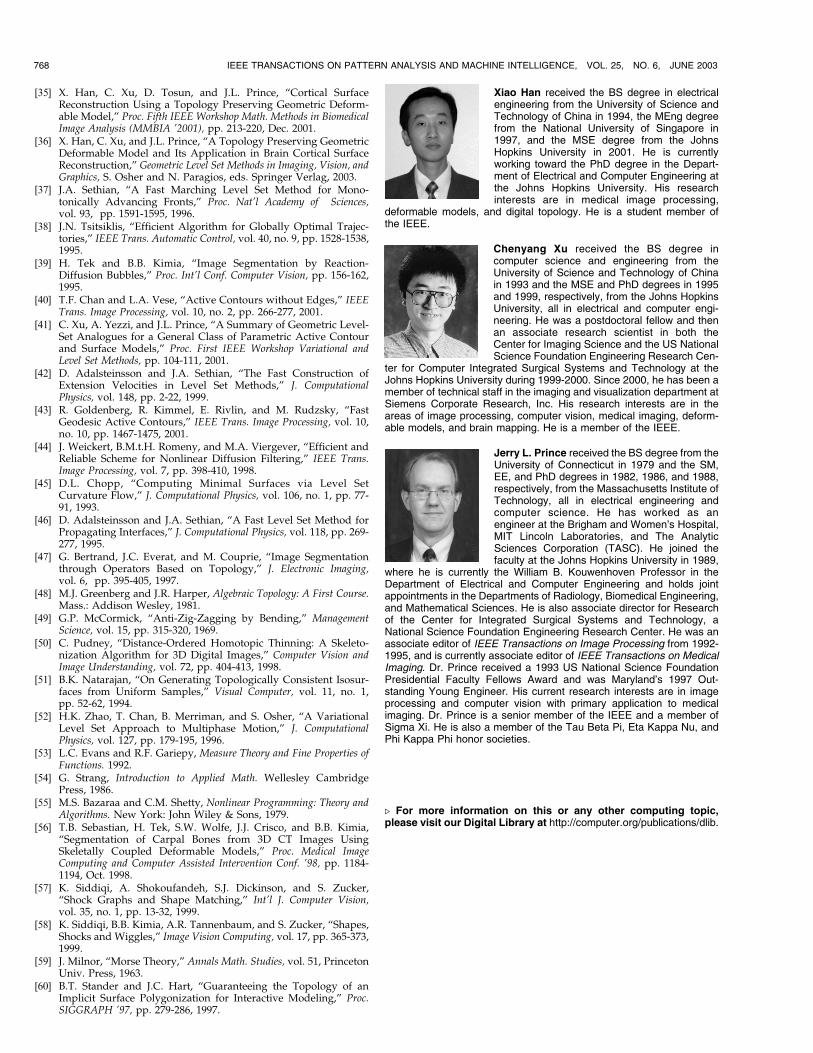
Xiao Han received the BS degree in electricalengineering from the University of Science andTechnology of China in 1994, the MEng degreefrom the National University of Singapore in1997, and the MSE degree from the JohnsHopkins University in 2001. He is currentlyworking toward the PhD degree in the Depart-ment of Electrical and Computer Engineering atthe Johns Hopkins University. His researchinterests are in medical image processing,
deformable models, and digital topology. He is a student member ofthe IEEE.
Chenyang Xu received the BS degree incomputer science and engineering from theUniversity of Science and Technology of Chinain 1993 and the MSE and PhD degrees in 1995and 1999, respectively, from the Johns HopkinsUniversity, all in electrical and computer engi-neering. He was a postdoctoral fellow and thenan associate research scientist in both theCenter for Imaging Science and the US NationalScience Foundation Engineering Research Cen-
ter for Computer Integrated Surgical Systems and Technology at theJohns Hopkins University during 1999-2000. Since 2000, he has been amember of technical staff in the imaging and visualization department atSiemens Corporate Research, Inc. His research interests are in theareas of image processing, computer vision, medical imaging, deform-able models, and brain mapping. He is a member of the IEEE.
Jerry L. Prince received the BS degree from theUniversity of Connecticut in 1979 and the SM,EE, and PhD degrees in 1982, 1986, and 1988,respectively, from the Massachusetts Institute ofTechnology, all in electrical engineering andcomputer science. He has worked as anengineer at the Brigham and Women’s Hospital,MIT Lincoln Laboratories, and The AnalyticSciences Corporation (TASC). He joined thefaculty at the Johns Hopkins University in 1989,
where he is currently the William B. Kouwenhoven Professor in theDepartment of Electrical and Computer Engineering and holds jointappointments in the Departments of Radiology, Biomedical Engineering,and Mathematical Sciences. He is also associate director for Researchof the Center for Integrated Surgical Systems and Technology, aNational Science Foundation Engineering Research Center. He was anassociate editor of IEEE Transactions on Image Processing from 1992-1995, and is currently associate editor of IEEE Transactions on MedicalImaging. Dr. Prince received a 1993 US National Science FoundationPresidential Faculty Fellows Award and was Maryland’s 1997 Out-standing Young Engineer. His current research interests are in imageprocessing and computer vision with primary application to medicalimaging. Dr. Prince is a senior member of the IEEE and a member ofSigma Xi. He is also a member of the Tau Beta Pi, Eta Kappa Nu, andPhi Kappa Phi honor societies.
. For more information on this or any other computing topic,please visit our Digital Library at http://computer.org/publications/dlib.
768 IEEE TRANSACTIONS ON PATTERN ANALYSIS AND MACHINE INTELLIGENCE, VOL. 25, NO. 6, JUNE 2003
Copyright © 2022 FDOKUMEN