A SWATH MOTHERSHIP CONCEPT FOR THE FAR SHORE WIND FARMS USING THE ENVIRONMENTAL PSYCHOLOGY NETWORK...
18
Marine Design 2015, 2-3 September 2015, London, UK © 2015: The Royal Institution of Naval Architects A SWATH MOTHERSHIP CONCEPT FOR THE FAR SHORE WIND FARMS USING THE ENVIRONMENTAL PSYCHOLOGY NETWORK MODEL S McCartan and T Thompson, EBDIG-IRC, Coventry University, UK, B Verheijden, Academy Minerva, Groningen, NL D Boote and T Colaianni, DITEN, Genoa University, Genoa, Italy I McFarlane and D Rose, Romica Engineering Ltd, UK C Anderberg and H Phalm, Division of Maritime Human Factors and Navigation, Chalmers University, SE SUMMARY The Toyota Production System (TPS) is a continuous improvement philosophy. It became the basis for the LEAN and Six Sigma manufacturing philosophies. A significant element of TPS is autonomation, or “automation with a human touch”. In the same way that lean techniques have been applied to automotive manufacturing, the principles of autonomation can be applied to offshore wind farm maintenance practices to improve turbine availability. This paper presents a mothership concept design to support an autonomation approach to offshore wind farm maintenance practices, developed through an implementation of the NetWork model of Environmental Psychology and biophilic design. The NetWork model encompasses both how and where work is done and how workers, processes and places are supported. It differs from previous Environmental Psychology models by focusing on the work that is to be done and how to enable it to be done most effectively. This knowledge informs the specification of furnishings, technologies, equipment and infrastructure that enable workers to make the best of wherever they work, to develop effective work practices, and to continue to adapt. This contrasts with the more traditional focus, which addresses only the places of work, and their efficient delivery and maintenance. The evolutionary basis for biophilia, is that contact with nature is a basic human need: not a cultural amenity, not an individual preference, but a universal primary need. The biophilia hypothesis and supporting research tells us that, as a species, we are still powerfully responsive to nature’s forms, processes, and patterns. The design process presented is a Transfer of Innovation from interior architecture where it is a well establish approach to produce highly productive and low stress working environments. The potential of this Human Factors focused approach to reduce risk and hence operational costs such as insurance is significant. 1. INTRODUCTION In 2014 the EWEA revised the wind energy scenarios for 2020 [1] to reflect the economic downturn and regulatory instability in a number of key European markets. Resulting in 11% lower predicted final power demand in 2020, which is not expected to increase above its 2008 peak until after 2020. Significantly affecting the stability of regulatory and market frameworks for offshore wind energy. These retrospective framework changes have had a significant negative impact on: investment plans; new orders; previous investment decisions; existing installations in markets across Europe. Given the expectations for energy demand, the rapidly changing national policy frameworks for wind energy, and EU policy framework to 2030, the EWEA is proposing three growth scenarios to 2020. For the Low scenario in 2020 Installed capacity increases by 41% compared to 2013 to 165.6 GW. Offshore installations are 19.5 GW. offshore installations produce 71.9 TWh. The combined wind energy production of 378.9 TWh covers 12.8% of total EU power demand. The effects of the economic crisis on power demand linger, pressure on public spending persists across Europe until the latter years of the decade. Instability in national regulatory frameworks in both mature and emerging markets continues. This instability makes it difficult to attract financing for new wind energy projects, especially in the offshore sector that struggles to de-risk. EU and international climate and energy policy post-2020 decisions are weak and unambitious, providing few extra stimuli for wind energy development. [2] The major challenge increasingly facing the offshore wind industry is regulatory risk, with the following key issues: conflicting political support for offshore wind; uncertainty with grid connection regimes; lack of a long- term stable market and regulatory framework. Evidently, the high level of uncertainty that comes with changing regulatory frameworks has slowed down offshore wind energy deployment in many European countries, not least in the two largest markets, the UK and Germany. By June 2013, there were 6 GW of offshore wind deployed in Europe. The UK accounted for 57%, followed by Denmark (21%), Belgium (8%) Germany (6%), Sweden (4%) and the Netherlands (3%). The European offshore wind energy industry needs to attract between €90 billion and €123 billion by 2020 to meet its deployment target of 40 GW. Should regulatory instability prevent the offshore industry from reaching its 40 GW target by 2020, even a conservative assumption of 25 GW would still require between €50 bn and €69 bn over this period. [1] The most critical strategic research agenda priority for offshore wind is to significantly lower the cost of energy in order to become competitive with conventional power generation by 2030. A key research topic for offshore wind technology development proposed by TPWind [3] is O&M. Where the key issues are to investigate versatile service fleets and safe access,
Transcript of A SWATH MOTHERSHIP CONCEPT FOR THE FAR SHORE WIND FARMS USING THE ENVIRONMENTAL PSYCHOLOGY NETWORK...
Marine Design 2015, 2-3 September 2015, London, UK
© 2015: The Royal Institution of Naval Architects
A SWATH MOTHERSHIP CONCEPT FOR THE FAR SHORE WIND FARMS USING
THE ENVIRONMENTAL PSYCHOLOGY NETWORK MODEL S McCartan and T Thompson, EBDIG-IRC, Coventry University, UK,
B Verheijden, Academy Minerva, Groningen, NL
D Boote and T Colaianni, DITEN, Genoa University, Genoa, Italy
I McFarlane and D Rose, Romica Engineering Ltd, UK
C Anderberg and H Phalm, Division of Maritime Human Factors and Navigation, Chalmers University, SE
SUMMARY
The Toyota Production System (TPS) is a continuous improvement philosophy. It became the basis for the LEAN and
Six Sigma manufacturing philosophies. A significant element of TPS is autonomation, or “automation with a human
touch”. In the same way that lean techniques have been applied to automotive manufacturing, the principles of autonomation can be applied to offshore wind farm maintenance practices to improve turbine availability. This paper
presents a mothership concept design to support an autonomation approach to offshore wind farm maintenance practices,
developed through an implementation of the NetWork model of Environmental Psychology and biophilic design. The
NetWork model encompasses both how and where work is done and how workers, processes and places are supported. It
differs from previous Environmental Psychology models by focusing on the work that is to be done and how to enable it
to be done most effectively. This knowledge informs the specification of furnishings, technologies, equipment and
infrastructure that enable workers to make the best of wherever they work, to develop effective work practices, and to
continue to adapt. This contrasts with the more traditional focus, which addresses only the places of work, and their
efficient delivery and maintenance. The evolutionary basis for biophilia, is that contact with nature is a basic human
need: not a cultural amenity, not an individual preference, but a universal primary need. The biophilia hypothesis and
supporting research tells us that, as a species, we are still powerfully responsive to nature’s forms, processes, and patterns. The design process presented is a Transfer of Innovation from interior architecture where it is a well establish
approach to produce highly productive and low stress working environments. The potential of this Human Factors
focused approach to reduce risk and hence operational costs such as insurance is significant.
1. INTRODUCTION
In 2014 the EWEA revised the wind energy scenarios for
2020 [1] to reflect the economic downturn and
regulatory instability in a number of key European
markets. Resulting in 11% lower predicted final power demand in 2020, which is not expected to increase above
its 2008 peak until after 2020. Significantly affecting the
stability of regulatory and market frameworks for
offshore wind energy. These retrospective framework
changes have had a significant negative impact on:
investment plans; new orders; previous investment
decisions; existing installations in markets across Europe.
Given the expectations for energy demand, the rapidly
changing national policy frameworks for wind energy,
and EU policy framework to 2030, the EWEA is
proposing three growth scenarios to 2020. For the Low scenario in 2020 Installed capacity increases by 41%
compared to 2013 to 165.6 GW. Offshore installations
are 19.5 GW. offshore installations produce 71.9 TWh.
The combined wind energy production of 378.9 TWh
covers 12.8% of total EU power demand. The effects of
the economic crisis on power demand linger, pressure on
public spending persists across Europe until the latter
years of the decade. Instability in national regulatory
frameworks in both mature and emerging markets
continues. This instability makes it difficult to attract
financing for new wind energy projects, especially in the
offshore sector that struggles to de-risk. EU and international climate and energy policy post-2020
decisions are weak and unambitious, providing few extra
stimuli for wind energy development. [2]
The major challenge increasingly facing the offshore
wind industry is regulatory risk, with the following key
issues: conflicting political support for offshore wind;
uncertainty with grid connection regimes; lack of a long-
term stable market and regulatory framework. Evidently,
the high level of uncertainty that comes with changing
regulatory frameworks has slowed down offshore wind
energy deployment in many European countries, not least in the two largest markets, the UK and Germany.
By June 2013, there were 6 GW of offshore wind
deployed in Europe. The UK accounted for 57%,
followed by Denmark (21%), Belgium (8%) Germany
(6%), Sweden (4%) and the Netherlands (3%). The
European offshore wind energy industry needs to attract
between €90 billion and €123 billion by 2020 to meet its
deployment target of 40 GW. Should regulatory
instability prevent the offshore industry from reaching its
40 GW target by 2020, even a conservative assumption
of 25 GW would still require between €50 bn and €69 bn over this period. [1]
The most critical strategic research agenda priority for
offshore wind is to significantly lower the cost of
energy in order to become competitive with conventional
power generation by 2030. A key research topic for
offshore wind technology development proposed by
TPWind [3] is O&M. Where the key issues are to
investigate versatile service fleets and safe access,
Marine Design 2015, 2-3 September 2015, London, UK
© 2015: The Royal Institution of Naval Architects
improve reliability and availability and research on full
cycle cost models for optimisation of asset management.
The implication being that vessels for installation and
O&M have to attract the digitally native generation to a
new sector, that must compete with land based as well as
offshore careers. This was identified as a key rationale
for the development of next generation motherships by
McCartan et al. [4]. RenewableUK annual report [5]
predicts 30,000 employees in the UK offshore wind
sector by 2020, contributing £7 billion Gross Value
Added each year.
1.1 TPM and Environmental Psychology
Total Productive Maintenance is based around having
zero breakdowns and production losses, and is one of the
foundation principles of the lean production system.
TPM evolved from suppliers to Toyota in Japan to enable
them to meet the demands of the TPS [6].TPM is a
philosophy that does not just focus on the ‘Maintenance
Department’ although maintenance does have a
significant part to play. TPM addresses all the reasons for equipment losses. Consistent standards including Overall
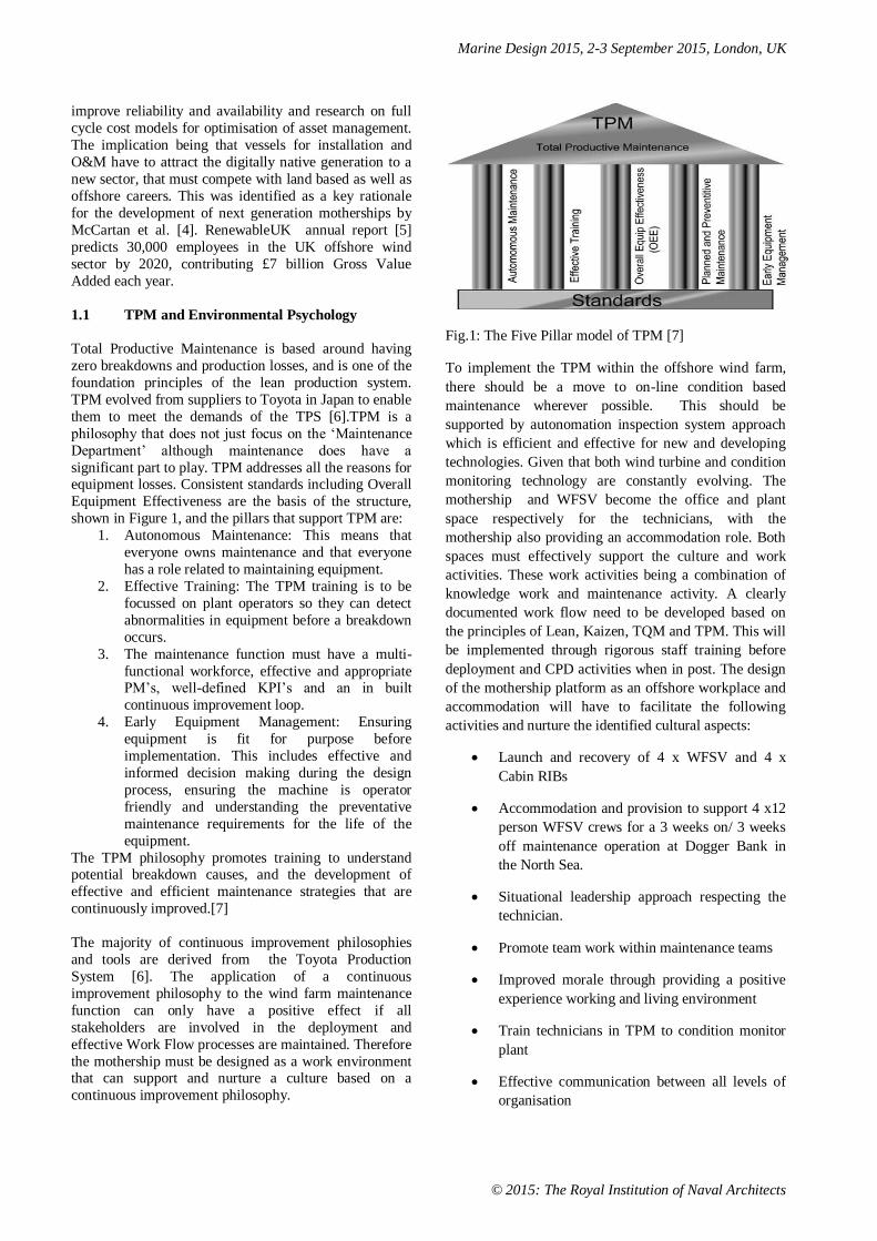
Equipment Effectiveness are the basis of the structure,
shown in Figure 1, and the pillars that support TPM are:
1. Autonomous Maintenance: This means that
everyone owns maintenance and that everyone
has a role related to maintaining equipment.
2. Effective Training: The TPM training is to be
focussed on plant operators so they can detect
abnormalities in equipment before a breakdown
occurs.
3. The maintenance function must have a multi-
functional workforce, effective and appropriate PM’s, well-defined KPI’s and an in built
continuous improvement loop.
4. Early Equipment Management: Ensuring
equipment is fit for purpose before
implementation. This includes effective and
informed decision making during the design
process, ensuring the machine is operator
friendly and understanding the preventative
maintenance requirements for the life of the
equipment.
The TPM philosophy promotes training to understand potential breakdown causes, and the development of
effective and efficient maintenance strategies that are
continuously improved.[7]
The majority of continuous improvement philosophies
and tools are derived from the Toyota Production
System [6]. The application of a continuous
improvement philosophy to the wind farm maintenance
function can only have a positive effect if all
stakeholders are involved in the deployment and
effective Work Flow processes are maintained. Therefore
the mothership must be designed as a work environment that can support and nurture a culture based on a
continuous improvement philosophy.
Fig.1: The Five Pillar model of TPM [7]
To implement the TPM within the offshore wind farm,
there should be a move to on-line condition based
maintenance wherever possible. This should be
supported by autonomation inspection system approach
which is efficient and effective for new and developing
technologies. Given that both wind turbine and condition
monitoring technology are constantly evolving. The
mothership and WFSV become the office and plant
space respectively for the technicians, with the
mothership also providing an accommodation role. Both
spaces must effectively support the culture and work
activities. These work activities being a combination of
knowledge work and maintenance activity. A clearly
documented work flow need to be developed based on
the principles of Lean, Kaizen, TQM and TPM. This will
be implemented through rigorous staff training before
deployment and CPD activities when in post. The design
of the mothership platform as an offshore workplace and
accommodation will have to facilitate the following
activities and nurture the identified cultural aspects:
Launch and recovery of 4 x WFSV and 4 x
Cabin RIBs
Accommodation and provision to support 4 x12
person WFSV crews for a 3 weeks on/ 3 weeks
off maintenance operation at Dogger Bank in
the North Sea.
Situational leadership approach respecting the
technician.
Promote team work within maintenance teams
Improved morale through providing a positive
experience working and living environment
Train technicians in TPM to condition monitor
plant
Effective communication between all levels of
organisation
Marine Design 2015, 2-3 September 2015, London, UK
© 2015: The Royal Institution of Naval Architects
Recognition of all suggestions and
achievements for teams and individuals
Environmental psychology is an interdisciplinary field of research that addressed the relationship between humans
and their surroundings. The term environment includes:
natural environments; social settings; built environments
learning environments; informational environments. The
discipline is both value oriented and problem oriented,
with the objective of solving complex environmental
problems to achieve individual wellbeing within a larger
society. [8] A critical tool to this approach is a model of
human nature that predicts the environmental conditions
under which humans will behave. This can help design,
manage, protect and/or restore environments that
enhance reasonable behaviour, predict the likely outcomes when these conditions are not met, and
diagnose problem situations. The field explores a diverse
range of issues including the following: the effect of
environmental stress on human performance; the
characteristics of restorative environments; human
information processing; promotion of durable
conservation behaviour. Environmental Psychology
relies on interaction with other disciplines in the design
field such as: architecture; interior design; urban
planning; industrial design; landscape architecture. [9]
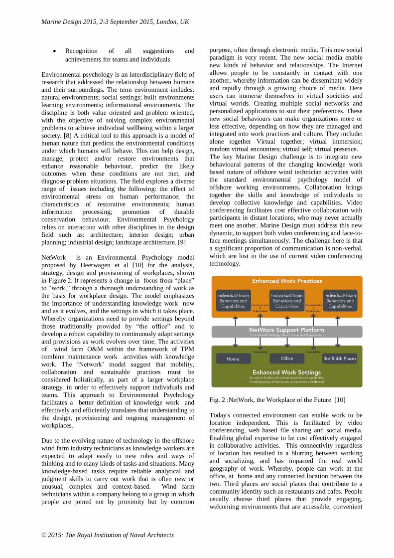
NetWork is an Environmental Psychology model
proposed by Heerwagen et al [10] for the analysis,
strategy, design and provisioning of workplaces, shown
in Figure 2. It represents a change in focus from “place”
to “work,” through a thorough understanding of work as
the basis for workplace design. The model emphasizes
the importance of understanding knowledge work now
and as it evolves, and the settings in which it takes place.
Whereby organizations need to provide settings beyond
those traditionally provided by “the office” and to
develop a robust capability to continuously adapt settings
and provisions as work evolves over time. The activities of wind farm O&M within the framework of TPM
combine maintenance work activities with knowledge
work. The ‘Network’ model suggest that mobility,
collaboration and sustainable practices must be
considered holistically, as part of a larger workplace
strategy, in order to effectively support individuals and
teams. This approach to Environmental Psychology
facilitates a better definition of knowledge work and
effectively and efficiently translates that understanding to
the design, provisioning and ongoing management of
workplaces.
Due to the evolving nature of technology in the offshore
wind farm industry technicians as knowledge workers are
expected to adapt easily to new roles and ways of
thinking and to many kinds of tasks and situations. Many
knowledge-based tasks require reliable analytical and
judgment skills to carry out work that is often new or
unusual, complex and context-based. Wind farm
technicians within a company belong to a group in which
people are joined not by proximity but by common
purpose, often through electronic media. This new social
paradigm is very recent. The new social media enable
new kinds of behavior and relationships. The Internet
allows people to be constantly in contact with one
another, whereby information can be disseminate widely
and rapidly through a growing choice of media. Here
users can immerse themselves in virtual societies and
virtual worlds. Creating multiple social networks and
personalized applications to suit their preferences. These
new social behaviours can make organizations more or
less effective, depending on how they are managed and integrated into work practices and culture. They include:
alone together Virtual together; virtual immersion;
random virtual encounters; virtual self; virtual presence.
The key Marine Design challenge is to integrate new
behavioural patterns of the changing knowledge work
based nature of offshore wind technician activities with
the standard environmental psychology model of
offshore working environments. Collaboration brings
together the skills and knowledge of individuals to
develop collective knowledge and capabilities. Video
conferencing facilitates cost effective collaboration with participants in distant locations, who may never actually
meet one another. Marine Design must address this new
dynamic, to support both video conferencing and face-to-
face meetings simultaneously. The challenge here is that
a significant proportion of communication is non-verbal,
which are lost in the use of current video conferencing
technology.
Fig. 2 :NetWork, the Workplace of the Future [10]
Today's connected environment can enable work to be
location independent. This is facilitated by video conferencing, web based file sharing and social media.
Enabling global expertise to be cost effectively engaged
in collaborative activities. This connectivity regardless
of location has resulted in a blurring between working
and socializing, and has impacted the real world
geography of work. Whereby, people can work at the
office, at home and any connected location between the
two. Third places are social places that contribute to a
community identity such as restaurants and cafes. People
usually choose third places that provide engaging,
welcoming environments that are accessible, convenient
Marine Design 2015, 2-3 September 2015, London, UK
© 2015: The Royal Institution of Naval Architects
places where they can easily socialize. Most third places
are not designed workspaces, as they are for drinking
coffee, in the case of a cafe. This results in users need to
adjust the space to work there. As the lighting and
furniture ergonomics are not specifically design for the
requirements of a work space, with limited security and
privacy. Alternative places deliberately designed for
work are specialised third places called “fourth places”.
Marine Design through the implementation of
Environmental Psychology models needs to provision the wind farm technician as a mobile worker. Using an
holistic approach which is responsive to changes in both
work and social structures with the aims of enabling
technicians to be effective users of the physical and
virtual spaces that they need to use and to provide the
full range of new work settings that are needed to support
emerging and evolving work patterns and practices.
NetWork [10] is an environmental psychology model,
which encompasses both how and where work is done
and how the technicians, processes and places are
supported. NetWork differs from other models as it focuses first on the work that is to be done, and on how
to enable it to be done most effectively. Where the aim is
to provision both the technician and workspaces with
furniture, technologies, equipment and infrastructure that
enable technicians to develop effective work practices,
and to continue to adapt. This is in contrast with the
conventional approach to office design, which addresses
only the places of work, and their efficient delivery and
maintenance.
The first stage involves understanding the needs and
activities of project teams and individual technicians and translate that understanding into requirements for settings
and infrastructure. This is achieved through developing a
user scenario of the vessel based on Design-Driven
Innovation dialogue with key stakeholders. The key
activities of the WFSV mothership are focussed in the
wind farm technicians as they are not used to sea
environment and the seafaring crew are in their typical
vessel role in the context of TPM.
Essentially the vessel has the bridge crew, the wind farm
vessel crews and the wind farm technician team. The wind farm technician team consist of four groups of 12
technicians of which there are 4 lead technicians who
manage and plan the maintenance schedule through
video conferencing dialogue with harbour based team
managers and simulation and planning teams. Who
develop and refine computer based models of system
maintenance and weather windows, and communicate
with mothership crew WFSV crew and lead technicians.
Lead technicians have a responsibility for encouraging
TPM culture onboard the mothership. Breaking down the
activities of the staff in terms of area of activity:
Technician apartment: sleeping, relaxing, VC communicating with family and friends, CPD
work, individual reporting Kaisen, showering
Communal lounge: team building, relaxing,
communicating
Canteen: eating, socialising, informal team
meetings, formal team meetings
Garden: biophilic space to enable the land based
technicians to experience well-being through a
connection with nature
Changing area and stairs: a transition between
the world of work and the leisure time
accommodation space
Briefing room: for communication before shift and debriefing after shift
Gym: a space for technicians to maintain fitness
while also engaging in knowledge work such as
CPD training videos and reporting of ideas and
issue
1.2 Vessel Specification and Operation
The WFSV mothership or SOV (Service Offshore
Vessel) will be designed to operate at Dogger Bank wind
farm in the North Sea. The purpose of the vessel will be to act as a safe haven for WFSV operating at the far
shore wind farms. It will operate on a 3 weeks on-3
weeks off basis and provide accommodation and interior
design affordances through the application of
Environmental Psychology including integrated IT to
facilitate a TPS approach to O&M, for a team of 50
technicians and project managers, who will not have had
significant offshore experience. The vessel to be
designed to Lloyd's Register SPS (Special Purpose Ships)
regulations, which due to the number of special persons
involved requires an implementation of the 13-36 PYC regulations for fire safety and means of escape. The
vessel must be able to store, service and launch 3-4
WFSV in 2.5m Hs, as well as 3-4 Cabin RIBs in Hs
1.5m. These CTVs will be chartered to facilitated an
optimised O&M strategy based on weather window and
predicted maintenance scheduling. To facilitate this
O&M operation the following crew and special persons
will be required:
4x Bridge crew: Captain; 1st mate; 2nd mate;
3rd mate
6 x Engineers = 3 engineers + 3 CTV service technicians
3 x deck crew
4 x hotel staff
2 x chefs
4 x WFSV crew
1 x IT technician
50 x wind farm technicians = 12 technicians x 4
WFSV + 2 reserve
This total of 74 crew and special persons will require
individual rooms, except for the hotel staff . Resulting in a requirement for 74 rooms including two cabins for
super annuary crew.

Marine Design 2015, 2-3 September 2015, London, UK
© 2015: The Royal Institution of Naval Architects
2. EXTERIOR DESIGN AND BIOPHILIA
The stylised exterior form has a structural glass roof
feature, enclosing a large interior garden space. Inspired
by superyachts and architectural forms the exterior has
an imposing presence of architecture upon the water. The
flowing sculptural features on the upper decks and the
use of a colour break help to give the simplistic
geometric form a sense of motion and elegance, as
shown in Figure 3.
Figure 3: Render of final exterior form proposal
Figure 4: Plan view sketch of interior garden with CAD
render of plan view
The second stage of the NetWork platform of support
involves creating new work settings and their
infrastructure, including those tools and protocols needed
by workers outside of the work place. The following
provisioning specification for interior areas was
developed from an analysis of the identified activities,
considering the y generation approach to developing
social networks, with a focus on informal collaboration
communication.
Engaging in the principles of biophilia, the central focal
point of the design is a large interior garden space with a
light canopy, shown in Figures 4, 5 and 6, to enable
previously land based technicians to experience well-being through a connection with nature. Due to the
specific nature of this user group, the mothership
platform is a SWATH to ensure minimal motion of the
vessel in the challenging weather conditions of the North
Sea. The garden space has a range of seating
configurations and seating locations designed to offer a
sense of privacy between them. To facilitate a range of
activities from individual to group socialising and
informal meetings. Connectivity is provided by tablets.
The inboard cabins connect with the garden area for
natural light, giving them the design meaning of a small apartment on land.
Figure 5: View of interior garden from seating area
Figure 6: View of interior garden from roof
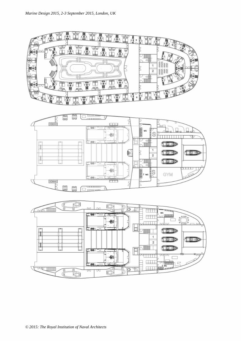
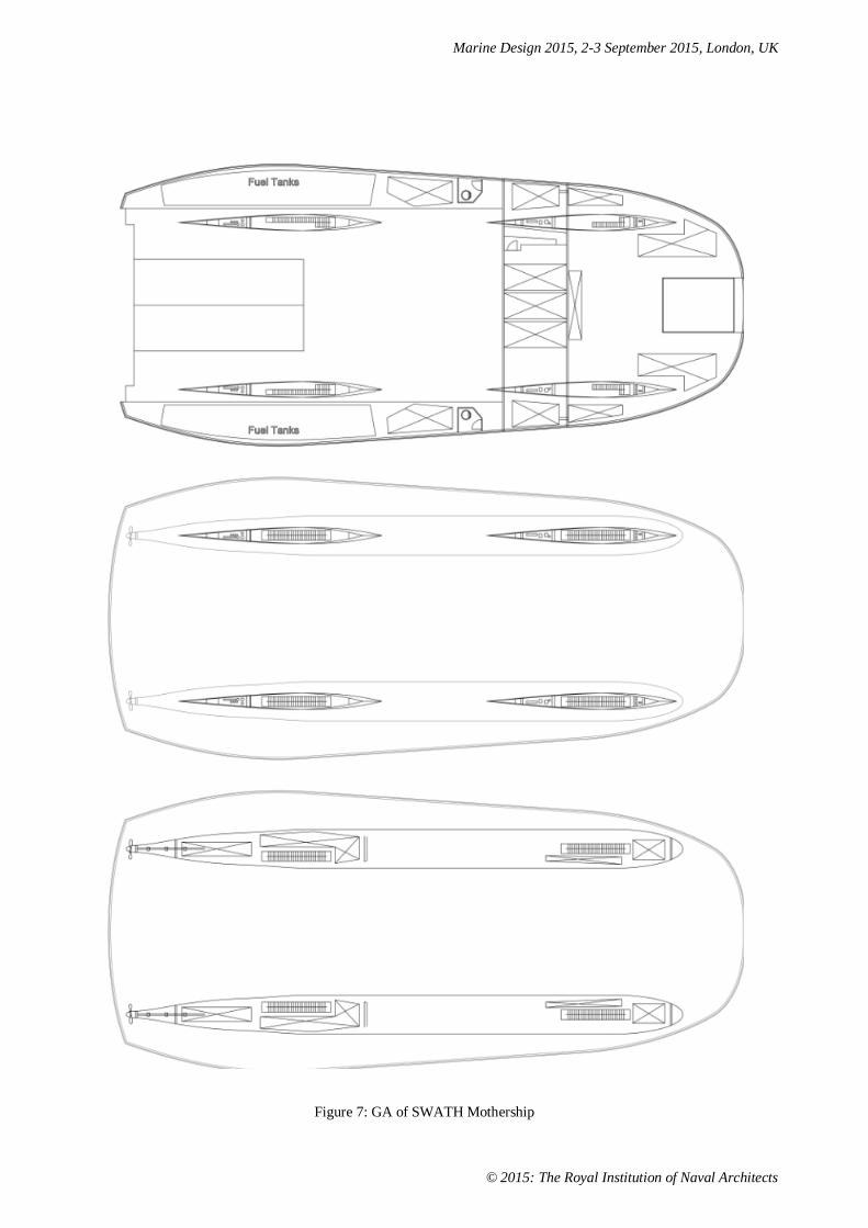
3. GA AND INTERIOR DESIGN
The GA shown in Fig.7, was developed by assigning space function and examining people flow, base on the
DDI generated scenario discussed in the implementation
of NetWork model. As discussed in the previous section
a large interior garden area informed by the principles of
biophilia was a key design feature. This architectural
feature provides all the technician rooms with natural
Marine Design 2015, 2-3 September 2015, London, UK
© 2015: The Royal Institution of Naval Architects
light and the inner apartments with the design meaning of
a small apartment with balcony. To achieve a formal
demarcation between living and working in the same
space WFSVs, briefing room and changing rooms are
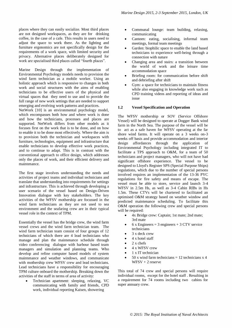
located in the lower decks. A perspective view of the
upper deck is shown in Figure 8. The canteen area at the
fore of the deck is shown as an empty space. The lounge
area due to a significant amount of daily usage is located
on the aft area of the vessel, where it has both a view of
the sea and internal garden. It provides a range of
adaptable spaces, booth seating and individual pod areas to facilitate individual, group and together/alone working
practices.
On the port side there is a glass walled adaptable space,
which is shown in the eight table configuration in Figure
9. The light fitting lowers on a cable system to combine
with the small tables to become a large board room table
for formal meetings as shown in Figure 10. Changing
from an office space for individuals to a meeting room
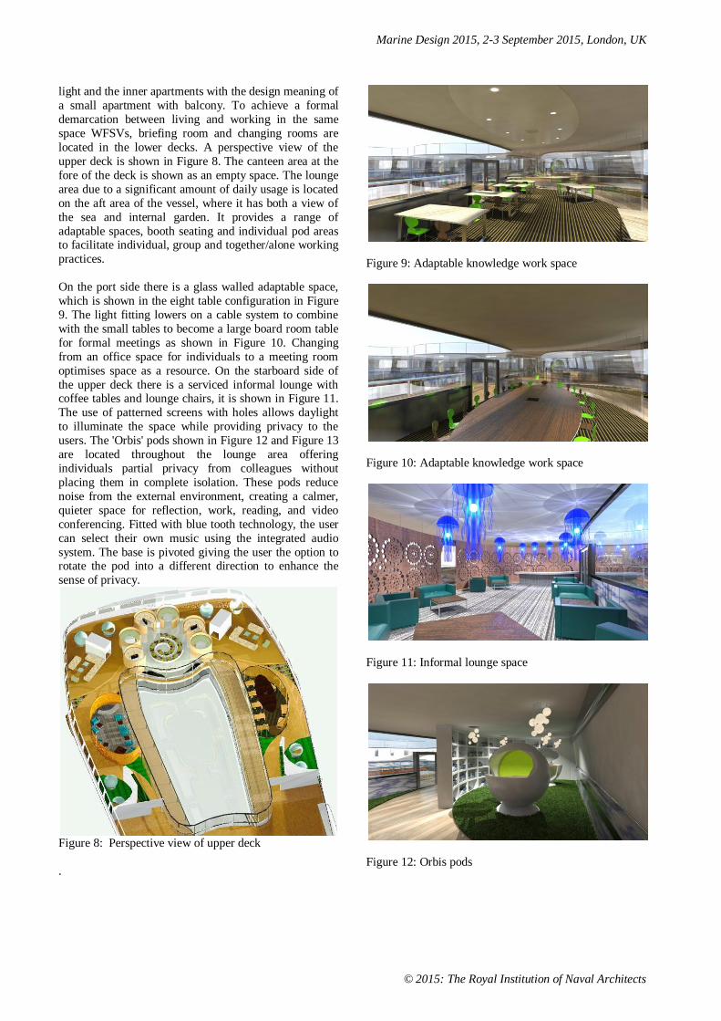
optimises space as a resource. On the starboard side of
the upper deck there is a serviced informal lounge with coffee tables and lounge chairs, it is shown in Figure 11.
The use of patterned screens with holes allows daylight
to illuminate the space while providing privacy to the
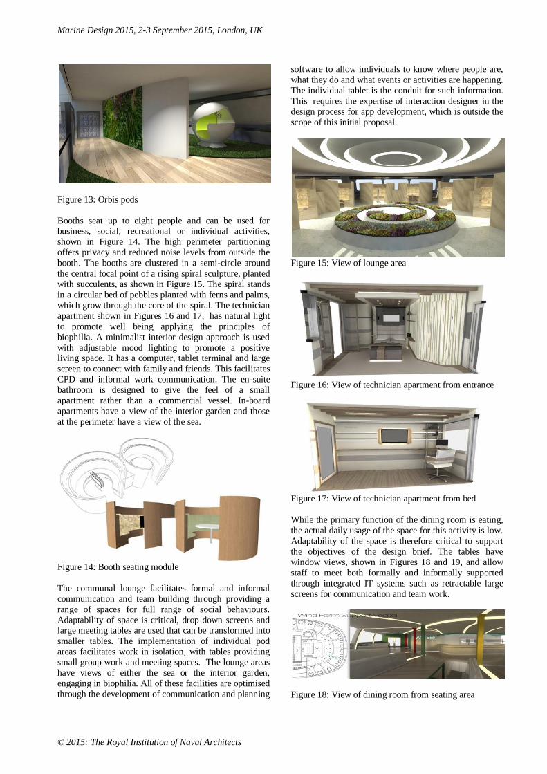
users. The 'Orbis' pods shown in Figure 12 and Figure 13
are located throughout the lounge area offering
individuals partial privacy from colleagues without
placing them in complete isolation. These pods reduce
noise from the external environment, creating a calmer,
quieter space for reflection, work, reading, and video
conferencing. Fitted with blue tooth technology, the user
can select their own music using the integrated audio
system. The base is pivoted giving the user the option to rotate the pod into a different direction to enhance the
sense of privacy.
Figure 8: Perspective view of upper deck
.
Figure 9: Adaptable knowledge work space
Figure 10: Adaptable knowledge work space
Figure 11: Informal lounge space
Figure 12: Orbis pods
Marine Design 2015, 2-3 September 2015, London, UK
© 2015: The Royal Institution of Naval Architects
Figure 13: Orbis pods
Booths seat up to eight people and can be used for business, social, recreational or individual activities,
shown in Figure 14. The high perimeter partitioning
offers privacy and reduced noise levels from outside the
booth. The booths are clustered in a semi-circle around
the central focal point of a rising spiral sculpture, planted
with succulents, as shown in Figure 15. The spiral stands
in a circular bed of pebbles planted with ferns and palms,
which grow through the core of the spiral. The technician
apartment shown in Figures 16 and 17, has natural light
to promote well being applying the principles of
biophilia. A minimalist interior design approach is used
with adjustable mood lighting to promote a positive living space. It has a computer, tablet terminal and large
screen to connect with family and friends. This facilitates
CPD and informal work communication. The en-suite
bathroom is designed to give the feel of a small
apartment rather than a commercial vessel. In-board
apartments have a view of the interior garden and those
at the perimeter have a view of the sea.
Figure 14: Booth seating module
The communal lounge facilitates formal and informal
communication and team building through providing a
range of spaces for full range of social behaviours.
Adaptability of space is critical, drop down screens and large meeting tables are used that can be transformed into
smaller tables. The implementation of individual pod
areas facilitates work in isolation, with tables providing
small group work and meeting spaces. The lounge areas
have views of either the sea or the interior garden,
engaging in biophilia. All of these facilities are optimised
through the development of communication and planning
software to allow individuals to know where people are,
what they do and what events or activities are happening.
The individual tablet is the conduit for such information.
This requires the expertise of interaction designer in the
design process for app development, which is outside the
scope of this initial proposal.
Figure 15: View of lounge area
Figure 16: View of technician apartment from entrance
Figure 17: View of technician apartment from bed
While the primary function of the dining room is eating,
the actual daily usage of the space for this activity is low.
Adaptability of the space is therefore critical to support
the objectives of the design brief. The tables have
window views, shown in Figures 18 and 19, and allow
staff to meet both formally and informally supported
through integrated IT systems such as retractable large
screens for communication and team work.
Figure 18: View of dining room from seating area

Marine Design 2015, 2-3 September 2015, London, UK
© 2015: The Royal Institution of Naval Architects
Figure 19: View of dining room from serving area
Living and working in the same space requires a formal
demarcation between activities, even though people
continue to work in fourth spaces. This is achieved by
locating the briefing room and changing room in the
lower decks. This means that the lower stairwell has to
communicate the design meaning of a transition between the formal work areas and the accommodation areas of
the vessel. The briefing room is essential for face-to-face
communication before a 12 hour maintenance shift and
afterwards for communication as a TPM activity. The
changing area shown in Figures 20 and 21, is designed as
a personal space with storage of work ware and storage
for personal items, to help the user develop an affinity
with the space. The use of simulated environment views
engages in biophilia. Given the loading time of WFSV
the changing provision is for half the total crew, using
domotic technology to identify crew members enables the changing room as a space to be shared by two crew
members at different times with security control on the
lockers, to make it a personalised space. The inclusion of
video conferencing technology to allow technicians to
make a brief connection with friends or family before
starting work will keep them socially connected.
Figure 20:View of changing room from shower
To help the technicians maintain fitness a gym is
implemented as a 4th space, fully equipped for
technicians to engage in knowledge work while
exercising on a treadmill or other exercise machine. These activities include report writing through voice
recognition software and CPD training material.
Figure 21: Perspective view of room
4. LAUNCH AND RECOVERY OF WFSV
A critical design challenge of the SOV is the
launch/recovery of the WFSV in 2.5m Hs and higher sea
states. Due to the proximity of the wet deck to the waves
in high sea states, an initial proposal was to launch the
Mainprize M002 using a retractable cantilever frame and
as shown in Figure 22. A schematic representation of the
lifting frame and winch plan is shown in Figure 23.
Figure 22: WFSV garage
Figure 23: Lifting frame and winch arrangement
A key aspect of launch/recovery of the WFSV in high
sea state is the need to constrain the motion of the vessel which the lifting frame is brought into contact with the
hull to prevent damage. To facilitate this a fendered
bollard is required for the WFSV to drive onto in order to
constrain the vessel motion. These would be vertical

Marine Design 2015, 2-3 September 2015, London, UK
© 2015: The Royal Institution of Naval Architects
tubes attached to the horizontal tube shown in Figure 22.
Where the horizontal bar is in the process of being
lowered below the waterline. This proposed solution
operates as follows:
When the transfer vessel is ready to be lifted the
bollard beam is lowered. This gives the transfer
vessels a surface to drive against at partial
throttle to restrict the relative motion and make
the lifting points easier to locate.
After the beams have been lowered the lifting
beam will be deployed 22.5m from the rear
garage. The lifting cradles will be lowered to the
water level and further lowered until their
highest point is 5.5m below the water line to
give a 3.5m clearance over the vessel’s 2m draft
in a sea state of 2.5m Hs.
The WFSV is driven onto the bollards under
partial throttle to constrain vessel motion. The
beam has a design factor of 5 against shearing
under torsion to avoid excess deflection. Once
the WFSV motion is constrained the lifting
cradle will be raised into contact with underside
of the catamaran hulls.
The FEA analysis of an initial proposal for a bollard
beam is shown in Figure 24. Where the Design Factor of
4 has been achieved for UKB steel I-beam with Max
stress = 63.6MPa. The risk of hull impact on the
horizontal beam in high sea states, combined with the
technical challenges of implementing a system in the
demi-hulls to retract the bollard beam from the water,
brought the feasibility of the solution into question.
Figure 24: FEA of initial bollard beam proposal
The lifting cradle has a design factor of 2.5 and is
constructed from universal beams. The initial design
shown in Figure 25 with four lifting points had a weight of 45 tonnes, which is over 50% of the load initially
required to be lifted. The modified design shown in
Figure 26, increased the number of lifting points to six.
This redistributed the loading enabling the weight of
these beams to be significantly reduced, reducing the
overall weight of the frame to 31 tonnes.
Figure 25:FEA of initial lifting frame design
Weight = 437kN
Max stress = 106MPa
Design factor = 2.47
Figure 26: FEA of modified lifting frame design
Weight = 295kN
Max stress = 62MPa
Design factor = 4.2
4.1 Launch/Recovery Design Solution
This initial proposal highlighted two of the key design
challenges. The first being the need to hold the vessel
sufficiently above the waterline in high sea state, the
significant moment effect of suspending 120 tons at the
back of the SWATH require a significant amount of
ballast. This proposal was a compromise between
available height of the wet deck above waterline while
maintaining vessel stability and the motion of the WFSV
in 2.5mHs+ during lifting using the rear area. The revised
design proposal shown in Figure 27, has a watertight loading bay from which the WFSV is launched
vertically. The safety issues are addressed through the
use of telescopic L shaped loading bay doors and a swing
space either side of the WFSV supported by both internal
and external fendering (not shown for clarity). Launching
form within the SOV significantly reducing the lifting
moment and hence ballast requirements. To recover the
vessel the telescoping loading bay doors are opened and
the lifting frame is lowered into the water, shown in
Figure 29. The retractable bollards are lowered into the
vertical position and locked in place. This is achieved by a single hydraulic ram supported by two structural
member which lock the bollards in the vertical position,
Marine Design 2015, 2-3 September 2015, London, UK
© 2015: The Royal Institution of Naval Architects
using a 5th wheel mechanism. The structural members
act to stabilise the bollards during side loading
conditions. When not in use the bollards are retracted
into the wet deck with a roller shutter cover. The WFSV
is driven onto the bollards at partial throttle to constrain
vessel motion. The lifting frame is then retracted lifting
the WFSV clear of the water and into the loading bay.
Any motion of the WFSV during the lifting process due
to wave impact is addressed through the swinging space
around the lifting frame and the implementation of
fendering around the loading bay.
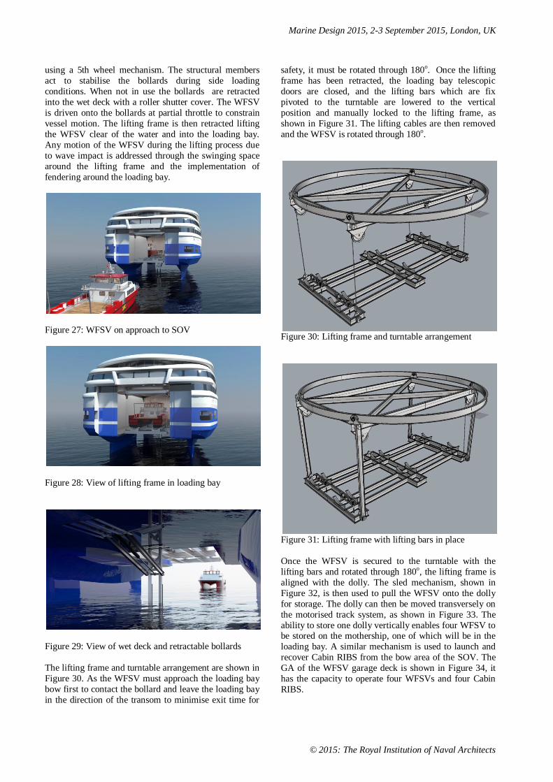
Figure 27: WFSV on approach to SOV
Figure 28: View of lifting frame in loading bay
Figure 29: View of wet deck and retractable bollards
The lifting frame and turntable arrangement are shown in
Figure 30. As the WFSV must approach the loading bay
bow first to contact the bollard and leave the loading bay
in the direction of the transom to minimise exit time for
safety, it must be rotated through 180o. Once the lifting
frame has been retracted, the loading bay telescopic
doors are closed, and the lifting bars which are fix
pivoted to the turntable are lowered to the vertical
position and manually locked to the lifting frame, as
shown in Figure 31. The lifting cables are then removed
and the WFSV is rotated through 180o.
Figure 30: Lifting frame and turntable arrangement
Figure 31: Lifting frame with lifting bars in place
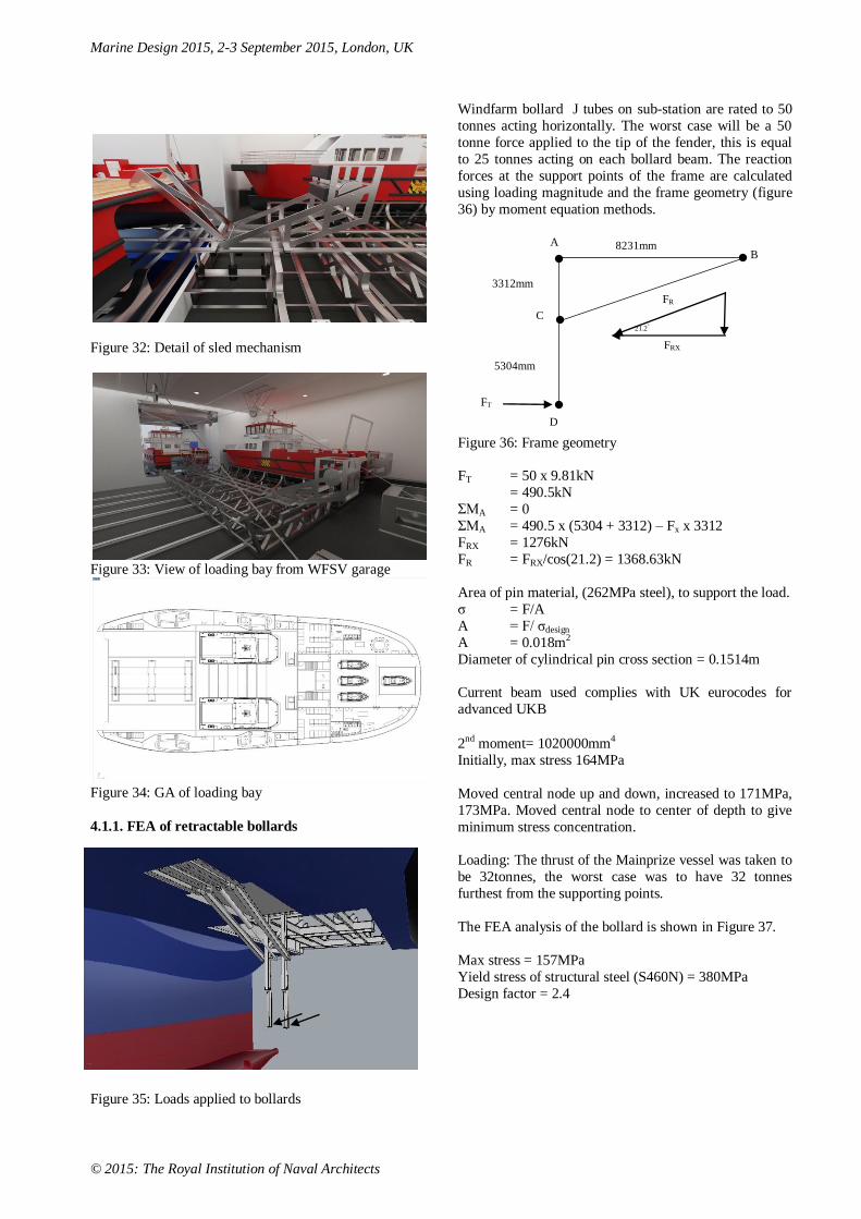
Once the WFSV is secured to the turntable with the
lifting bars and rotated through 180o, the lifting frame is
aligned with the dolly. The sled mechanism, shown in
Figure 32, is then used to pull the WFSV onto the dolly
for storage. The dolly can then be moved transversely on
the motorised track system, as shown in Figure 33. The
ability to store one dolly vertically enables four WFSV to be stored on the mothership, one of which will be in the
loading bay. A similar mechanism is used to launch and
recover Cabin RIBS from the bow area of the SOV. The
GA of the WFSV garage deck is shown in Figure 34, it
has the capacity to operate four WFSVs and four Cabin
RIBS.
Marine Design 2015, 2-3 September 2015, London, UK
© 2015: The Royal Institution of Naval Architects
Figure 32: Detail of sled mechanism
Figure 33: View of loading bay from WFSV garage
Figure 34: GA of loading bay
4.1.1. FEA of retractable bollards
Figure 35: Loads applied to bollards
Windfarm bollard J tubes on sub-station are rated to 50
tonnes acting horizontally. The worst case will be a 50
tonne force applied to the tip of the fender, this is equal
to 25 tonnes acting on each bollard beam. The reaction
forces at the support points of the frame are calculated
using loading magnitude and the frame geometry (figure
36) by moment equation methods.
Figure 36: Frame geometry
FT = 50 x 9.81kN
= 490.5kN
ΣMA = 0
ΣMA = 490.5 x (5304 + 3312) – Fx x 3312
FRX = 1276kN
FR = FRX/cos(21.2) = 1368.63kN
Area of pin material, (262MPa steel), to support the load.
σ = F/A
A = F/ σdesign
A = 0.018m2
Diameter of cylindrical pin cross section = 0.1514m
Current beam used complies with UK eurocodes for
advanced UKB
2nd moment= 1020000mm4
Initially, max stress 164MPa
Moved central node up and down, increased to 171MPa,
173MPa. Moved central node to center of depth to give
minimum stress concentration.
Loading: The thrust of the Mainprize vessel was taken to
be 32tonnes, the worst case was to have 32 tonnes
furthest from the supporting points.
The FEA analysis of the bollard is shown in Figure 37.
Max stress = 157MPa
Yield stress of structural steel (S460N) = 380MPa
Design factor = 2.4
FT
D
FRX
FR
A
C
B
3312mm
8231mm
5304mm
21.2°

Marine Design 2015, 2-3 September 2015, London, UK
© 2015: The Royal Institution of Naval Architects
Figure 37: FEA analysis of the bollard
4.1.2 FEA of Storage Frame
The FEA of the storage frame is shown in Figure 38. The
weight of the 90tonne Mainprize vessel when loaded,
including a heave loading factor to account for rough sea
conditions resulted in a load of 1471.5kN. The resulting
maximum stress was 3.2MPa. For standard structural
steel (Ys=262MPa) results of initial FEA analysis show
the current design has a high safety factor of 81, which
could be reduced to 10 and the design would still be
acceptable. The frame could be optimized for weight by removing unloaded members, reducing the number of
sub-frames and using smaller beam sections.
Figure 38: FEA of storage frame
4.1.3 FEA of Turntable Lifting Bars
The full load of the Mainprize M002 in 2.5m Hs is 150tonne in 2.5Hs. As there are 4 lifting bars, the
force on each bar is 37.5tonnes (368kN). The
design stress below is based on a safety factor of 5.
σdesign = yield stress/5 = 262/5MPa = 52.4MPa
Which requires the beam to have the following cross sectional area.
A = 368kN/52.4MPa = 70.299cm2
The closest standard beam has 76.9cm2 cross
section, resulting in a maximum stress of 48.1MPa, shown below in Figure 39.
Figure 39: FEA of lifting bar
4. DISCUSSION
A key objective in O&M is the reduction in operational
cost. In this SOV proposal it is achieved through a multi vessel O&M strategy, in which Cabin RIBS can operate
in 1.5m Hs or possibly higher with the use of innovative
fendering and motion seats. Offering both a significant
fuel cost saving and an acquisition cost which is less than
10% that of a catamaran WFSV. Advances in catamaran
design could potentially result in vessels capable of 3.0m
Hs, which currently is only achievable by using a
SWATH type vessel, which have significantly higher
fuel consumption than a catamaran.
The critical design challenge of this SOV was the
launch/recovery of the catamarans and Cabin RIBs. Here there was a need for design compromise between
operational safety and mothership stability. Having
sufficient wet deck height to safely lift the WFSV above
the waves through a horizontal door in the wet deck
would make the vessel unstable. The initial concept of a
transom mounted cantilever davit solved the wave height
issue but produce a significant increase in loading
moment requiring significant ballasting. The wide
loading bay with fendering is a compromise significantly
reducing ballasting requirements and addressing risk of
impact relating to vessel movement caused by high sea states. In the initial proposal there was a significant risk
of the vessel grounding on the horizontal bar of the
bollards. The revised proposal resolves this issue through
the implementation of a retractable structurally stabilized
bollard structure capable of supporting an appropriate
level of side load.To lift under designed load sea
conditions the WFSV must be lifted rapidly out of the
air/water interface to avoid impact loading after the

Marine Design 2015, 2-3 September 2015, London, UK
© 2015: The Royal Institution of Naval Architects
initial lift contact. The winches installed should be
tension compensated to ensure the load on the lifting
system does not exceed the design load off the lifting
equipment. There should also be a latching system
implemented between the hulls and the lifting cradle so
that they are in constant contact, this would avoid snap
loading. These features will be developed in the further
work of the authors.
The transfer of crew and equipment to the turbine is a
critical part of the process for safety of the personnel and for the transfer of the maintenance equipment. The
turbine structure is fixed to the seabed while the transfer
vessels are subject to wave motion. Current operations
are carried out in 2.5mHs sea conditions however
2.5mHs only describes the height. The main point from
the sea condition is how the heave rate of the transfer
vessel is affected during the transfer of personnel and
equipment, this describes how much the vessel is
accelerating. This takes account of the height of the wave
and the period. Due to the direction of the waves/sea the
boat will display different characteristics of heave rate depending on its location around the turbine mast. There
will be a point where the heave rate is at its lowest and if
this could be accessed and moored to, it would be the
safest point for the transfer to take place. The same
principles are a key consideration for the launch/recovery
of the WFSV from/to the mothership. The authors will be
developing solutions to address this challenge in further
work.
Vessels for installation and O&M have to attract the
digitally native generation to a new sector, that must
compete with land based as well as offshore careers. This was identified as a key rationale for the development of
next generation motherships by McCartan et al [4]. To
ensure recruitment and retention the interior design and
user experience must engage the emotional design needs
of the user. This is achieved by engaging in biophilia
through the principles of Environmental Psychology in
the design process. On this basis a Design-Driven
Innovation approach to the implementation of the
NetWork Environmental Psychology model was used.
The GA and interior design detail were developed
through DDI dialogue with design interpreters including: operators; Naval Architect consultancies specialising in
Wind farm and accommodation vessels; superyacht
designers; interior designers. As part of which the
developed scenario of operation and activity considered
the needs of individuals in terms of operational task,
communication and leisure time. The use of different
types of space facilitates the full range of social
behaviours.
The new social behaviours can make organizations more
effective, when they are managed and integrated into
work practices and culture, through an effective implementation of technology addressing the challenges
they pose. These are [10]:
Alone together – working in the presence of other people
but not interacting with them. As people prefer to avoid
isolation and can find motivation in the atmosphere of a
crowd.
Virtual together – working with people in widely
dispersed locations, connected through video
conferencing technology. Here initial face-to-face
meetings are required to establish a rapport.
Virtual immersion – using media to create, learn and play. Such as the use virtual games to develop skills and
test knowledge in ways that are more engaging and
realistic than standard training methods.
Random virtual encounters – Internet applications can
provide random connections to people located in
different places. Forums, message boards and chat rooms
draw strangers together, usually around some common
interest, such as Linkedin.
Virtual self –Realistic avatars representing people at virtual meetings. This has the potential to support the
critical communication that occurs via the nuances of
social behaviour and create a sense of belonging.
Virtual presence – using video cameras to monitor
what’s happening at a remote site: the turbine;
technician's home; technicians children’s day care centre.
This facilitates both the TPM process and the social
connection required to support the challenges of working
away from home on a 3 weeks on/ 3 weeks off work
pattern.
All of these social behaviours have been implemented in
the range of spaces designed, through the DDI developed
scenario. The objective of which was to achieve a
positive living environment and a productive low stress
working environment. Where the application of
Environmental Psychology is a Transfer of Innovation
from the built environment to the commercial marine
sector. This is an integral part of the Marine Design
process which is a Human Systems Integration approach.
Human Factors approaches can significantly reduce
through life design costs of vessel and systems. As an example of HF implementation, incidents and accidents
in the Maersk shipping company decreased by a third
after the introduction of Bridge Resource Management
(BRM) training. Resulting in the reduction of insurance
premiums by 15%. [11]
5. CONCLUSION
The mothership proposal addresses the key issue of
offshore wind O&M operation costs, through facilitating
an optmised O&M strategy based on two vessel types
with very different Hs capability and operational cost. This has been achieved through a proposed technology
innovation in the launch and recovery system. The
proposed exterior form needs to be evaluated in terms of
Marine Design 2015, 2-3 September 2015, London, UK
© 2015: The Royal Institution of Naval Architects
the emotional response of stakeholders. Given the
significant ‘knowledge work’ nature of the technicians
role in the O&M activities in the offshore wind sector,
Environmental Psychology offers a significant
opportunity for Transfer of Innovation from the built
environment to the commercial marine sector. The
‘NetWork’ model [10] offers a more complete approach
to the support for work based on thoroughly
understanding what work is and how it is carried out;
provisioning individuals, teams and the places over
which the organization has control or influence. As part of a Human Systems Integration approach it would have
a similar potential to BRM in terms of reduce operating
costs such as insurance. The critical activity for Marine
Designers is to engage in the development of DDI
scenario with stakeholders which delineates the
behaviours and processes that are most important and
then to evaluate the design proposals through further
dialogue with stakeholders.
6. ACKNOWLEDGEMENTS
The authors wish to thank Captain Bob Mainprize of
Mainprize Offshore Ltd, for his permission to use the
M02 Wind Farm Support Vessel in this project and for
the significant technical discussion and user perspective
he contributed to the Design-Driven Innovation Process.
The authors also wish to thank Dr Albert Nazarov of
Albatross Marine Design for providing the Cabin RIB
design for this project and his support in technical
discussions. The authors gratefully acknowledge the
grant support received to carry out the work presented in
this paper as an integral part of the Leonardo TOI funded
project EBDIG-WFSV, funded under the EU Lifelong Learning Programme, grant number: UK/13/LLP-
LdV/TOI-621. The content of the publication is the sole
responsibility of the authors, the European Commission
is not liable for any use that may be made of the
information. The initial exterior concept and GA were
developed by Daniel Caddick and the detailed interior
concepts by Mark Hopper and Wrox James during their
professional internship with EBDIG-IRC. All of whom
are students of the Department of Industrial Design at
Coventry University.
7. REFERENCES
1. ARAPOGIANNI, A., MOCCIA, J., WILKES,
J., and GENACHTE, A-B., ' Where's the money
coming from? Financing offshore wind farms',
report by the European Wind Energy
Association Published November 2013 ISBN:
978-2-930670-06-5
2. MOCCIA, J., European Wind Energy
Association (EWEA) Justin Wilkes (EWEA),
Iván Pineda (EWEA) and Giorgio Corbetta Wind energy scenarios for 2020. report by the
European Wind Energy Association, July 2014
3. European Wind Energy Technology Platform
Strategic Research Agenda /Market Deployment
Strategy March 2014
4. MCCARTAN, S., VERHEIJDEN, B.,
LUTZHOFT, M., and BOOTE, D., 'Design-
Driven Innovation: Mothership concepts for
accessing the far shore wind farms', RINA
Conference: Design & Operation of Wind Farm
Support Vessels, RINA HQ, London, 29-30
January 2014.
5. BROWN,H., and BRUCE, A., 'Offshore Wind
Programme Board 2015 Annual Report',
RenewableUK, March 2015
6. LIKER, J.K., 'The Toyota Way: 14 management
principles from the worlds greatest
manufacturer', McGraw-Hill publishing, New
York, 2004
7. SUZUKI, T.,'TPM Project Management', ISBN: 978-8190356473, 2012
8. DE YOUNG, R., 'Environmental Psychology
Overview', In Ann H. HUFFMAN, A.H., and
KLEIN, S., 'Green Organizations: Driving
Change with IO Psychology', p.17-33,
Routledge, 2013.
9. GIFFORD, R., 'Environmental Psychology:
Principles and Practice', (4th ed.). Colville,
WA: Optimal Books, 2007.
10. HEERWAGEN, J., ANDERSON, D., and
PORTER, W.,' NetWork: The Future
Workplace', Allsteel commissioned paper,
2012, available at
http://cms.allsteeloffice.com/SynergyDocument
s/FinalNetWorkPaper.pdf, accessed 05/01/15.
11. Byrdorf, P., Human Factors and Crew Resource
Management. An example of successfully
applying the experience from CRM
programmes in the Aviation World to the Maritime World. Paper presented at the 23rd
Conference of the European Association for
Aviation Psychology, September, Vienna, 1998.
9. AUTHORS BIOGRAPHY
Dr Sean McCartan holds the current position of Course
Tutor, Boat Design at Coventry University, UK. His key
research area is TOI (Transfer of Innovation) from other
sectors to the marine industry, in the areas of Design-
Driven Innovation (DDI), advanced visualisation and
Human Systems Integration(HSI). He leads the EBDIG (European Boat Design Innovation Group) network,
which includes Chalmers University; Genoa University;
TU-Delft; and a number of leading European marine
Marine Design 2015, 2-3 September 2015, London, UK
© 2015: The Royal Institution of Naval Architects
design consultancies. He is currently project co-ordinator
for the Leonardo TOI project EBDIG-WFSV (European
Boat Design Innovation Group - Wind Farm Support
Vessels), which aims to develop online training material
for Naval Architects in the subject areas of: Human
Factors; WFSV design (Industrial Design); WFSV
mothership design (Industrial Design).
Tim Thompson holds the current position of part-time
CAD lecturer in the Department of Industrial Design at
Coventry University, UK. He is currently project Research Assistant for the Leonardo TOI project
EBDIG-WFSV (European Boat Design Innovation
Group - Wind Farm Support Vessels). His CAD teaching
is informed by his professional practice within his design
consultancy, which specialises in photorealistic
visualisation for the superyacht design and interior
design industry.
Bob Verheijden holds the current position of Head of
Department Design, Academy Minerva, Groningen, NL
He has over 20 years professional practice in the following disciplines: architecture; urban planning;
interior design; product design; multimedia; brand
development. He is a Member of the BKVB (The
Netherlands Foundation for Visual Arts, Design and
Architecture), and has won a number of prestigious
awards for his architectural and furniture designs.
Prof Dario Boote holds the current position of Ship
Structure Professor at the Naval Architecture section of
the Department of Electrical, Electronic, Tele-
communications Engineering and Naval Architecture
(DITEN) of the University of Genoa. He is the Chairman of the Bachelor and Master Course in Yacht Design in La
Spezia. His initial experiences include a long research
activity in the field of Ship and Offshore Structures
followed, since 2000, by an intense activity in the field of
sailing and motor yachts. From 2009 to 2012 he has been
Chairman of the V.8 ISSC Committee on "Yacht Design"
Dr Tommaso Colaianni, graduated in 2001 at
Department of Naval Architecture and Marine
Engineering of the Genova University, he has a PhD in
Ship Design, specialized in Unconventional Ships, mainly involved in researches about ships structures
design using numerical methods. He is also a free-lance
technical consultant
Ian McFarlane currently holds the position of Business
Development Manager at Romica Engineering Ltd. He is
a results-orientated Senior Sales Executive/Head of
Business Development with a background within the
marine industry and over 10 years’ experience in
developing and implementing innovative product sales
and business development strategies for prestigious
organisations in the maritime sector.
Daniel Rose is currently a Engineering placement
student with Romica Engineering Ltd.
Christopher Anderberg is working with development
of Offshore and Dynamic Positioning Operations in the
division Maritime Human Factors and Navigation. After
completed master studies and BSc degree at Chalmers
University of Technology, he worked in
Walleniusrederierna as mate of ocean-going fleet.
Eventually he joined a "Bowloading Tanker" in the North
Sea. He has participated in several advanced operations
in Dynamic Positioning (DP), anchor handling, ice
management, offshore support, and more. Several of these have been implemented in Arctic environments
Henrik Pahlm currently holds the position of lecturer
and head of division of Maritime Environment and
Energy Systems at Chalmers University of Tecnology.
He has a background as Marine engineer mostly working
as Chief engineer and 1st engineer during the last
decades. Henrik also has a MSc in Shipping and Marine
Technology. He is teaching and supervising in different
subjects within the competence area.

Marine Design 2015, 2-3 September 2015, London, UK
© 2015: The Royal Institution of Naval Architects
Marine Design 2015, 2-3 September 2015, London, UK
© 2015: The Royal Institution of Naval Architects
Marine Design 2015, 2-3 September 2015, London, UK
© 2015: The Royal Institution of Naval Architects
Figure 7: GA of SWATH Mothership