ASI-T-570GA4NT/D - All Shore Industries
19
ASI-T-570GA4NT/D All Shore Industries, Inc. One Edgewater Plaza, Staten Island, NY 10305 Email: [email protected] Item Contents Unit Size 5.7 inch Resolution 640(RGB) x 480 / Interface TTL / Technology type a-si TFT / Pixel pitch 0.06x0.18 mm Pixel Configuration R.G.B. Stripe Outline Dimension (W x H x D) 127.0x 98.43x9.6 mm Active Area 115.2 x 86.4 mm Display Mode Transmissive, Normal white / Viewing Direction 12 O’clock / Backlight Type LED /
-
Upload
khangminh22 -
Category
Documents
-
view
4 -
download
0
Transcript of ASI-T-570GA4NT/D - All Shore Industries

ASI-T-570GA4NT/D
All Shore Industries, Inc. One Edgewater Plaza, Staten Island, NY 10305 Email: [email protected]
Item Contents Unit
Size 5.7 inch
Resolution 640(RGB) x 480 /
Interface TTL /
Technology type a-si TFT /
Pixel pitch 0.06x0.18 mm
Pixel Configuration R.G.B. Stripe
Outline Dimension (W x H x D) 127.0x 98.43x9.6 mm
Active Area 115.2 x 86.4 mm
Display Mode Transmissive, Normal white /
Viewing Direction 12 O’clock /
Backlight Type LED /

Page 2 of 19
Record of Revision
Date Revision No. Summary
All Shore Industries, Inc. One Edgewater Plaza, Staten Island, NY 10305 Email: [email protected]
ASI-T-570GA4NT/D

Page 3 of 19
1. Scope This data sheet introduces the specification of ASI-T-570GA4NT/D active matrix TFT module. It is composed of a color TFT-LCD panel, driver ICs, FPC, Touch panel and a backlight unit. The 5.7′′ display area contains 640(RGB) x 480 pixels.
2. Application Digital equipments which need color display, POS, medical equipments and industrial quipments..
3. General Information
Item Contents Unit
Size 5.7 inch
Resolution 640(RGB) x 480 /
Interface TTL /
Technology type a-si TFT /
Pixel pitch 0.06x0.18 mm
Pixel Configuration R.G.B. Stripe
Outline Dimension (W x H x D) 127.0x 98.43x9.6 mm
Active Area 115.2 x 86.4 mm
Display Mode Transmissive, Normal white /
Viewing Direction 12 O’clock /
Backlight Type LED /
All Shore Industries, Inc. One Edgewater Plaza, Staten Island, NY 10305 Email: [email protected]
ASI-T-570GA4NT/D

Page 4 of 19
4. Outline Drawing
All Shore Industries, Inc. One Edgewater Plaza, Staten Island, NY 10305 Email: [email protected]
ASI-T-570GA4NT/D

Page 5 of 19
5. Interface signals
Pin NO. SYMBOL DESCRIPTION
1 U/D Up or Down Display Control 2 NC No Connection 3 Hsync Horizontal SYNC. 4 VLED Power Supply for LED Driver circuit 5 VLED Power Supply for LED Driver circuit 6 VLED Power Supply for LED Driver circuit 7 VCC Power Supply for LCD 8 Vsync Vertical SYNC. 9 DE Data Enable
10 X2 Touch Panel control (Left) 11 Y1 Touch Panel control (Up) 12 ADJ Brightness control for LED B/L 13 B5 Blue Data 5 (MSB) 14 B4 Blue Data 4 15 B3 Blue Data 3 16 VSS Power Ground 17 B2 Blue Data 2 18 B1 Blue Data 1 19 B0 Blue Data 0 (LSB) 20 VSS Power Ground 21 G5 Green Data 5 (MSB) 22 G4 Green Data 4 23 G3 Green Data 3 24 VSS Power Ground 25 G2 Green Data 2 26 G1 Green Data 1 27 G0 Green Data 0 (LSB) 28 VSS Power Ground 29 R5 Red Data 5 (MSB) 30 R4 Red Data 4 31 R3 Red Data 3 32 VSS Power Ground 33 R2 Red Data 2 34 R1 Red Data 1 35 R0 Red Data 0 36 X1 Touch Panel control (Right) 37 Y2 Touch Panel control (Down) 38 DCLK Clock Signals ; Latch Data at the Falling Edge 39 VSS Power Ground 40 L/R Left or Right Display Control
Note 1: ADJ is brightness control Pin. The larger of the pulse duty is, the higher of the brightness. Note 2: ADJ signal is 0~3.3V.Operation frequency is 20KHz Note 3: VSS PIN must be grounding, can not be floating.
All Shore Industries, Inc. One Edgewater Plaza, Staten Island, NY 10305 Email: [email protected]
ASI-T-570GA4NT/D

Page 6 of 19
Note 4:U/D and L/R control Function
L/R
U/D
Function
1
0
Normally display
0
0
Left and Right opposite
1
1
Up and Down opposite
0
1
Left and Right opposite,Up and Down opposite
Note 5:If DE signal is fixed low, SYNC mode is used. Otherwise, DE mode is used.
6.
Absolute maximum Ratings
6.1. Electrical Absolute max. ratings
Parameter
Symbol
MIN
MAX
Unit
Remark
Power supply voltage
VCC
-0.3
5.0
V
Logic input voltage
VI
-0.3
VCC +0.5
V
6.2.
Environment Conditions
Item
Symbol
MIN
MAX
Unit
Remark
Operating Temperature
TOPR
-20
70
℃
Storage Temperature
TSTG
-30
80
℃
6.3. LED Backlight Absolute max. ratings
Item
Symbol
MIN
MAX
Unit
Remark
LED Forward Current
ILED
--
25
mA
One LED
All Shore Industries, Inc. One Edgewater Plaza, Staten Island, NY 10305 Email: [email protected]
ASI-T-570GA4NT/D

Page 7 of 19
7.
Electrical Specifications
7.1 Electrical characteristics VSS=0V,DCLK=25MHz,Ta=25°C
Item
Symbol
MIN
TYP
MAX
Unit
Remark
Power Supply voltage
VCC
3.0
3.3
3.6
V
Input Signal Voltage
VIL
0
--
0.3VCC
V
VIH
0.7VCC
--
VCC
V
ADJ input voltage VIL
0
--
0.3
V
VIH
3.0
--
3.3
V
ADJ frequency
19K
20K
21K
Hz
Power Supply Current
ICC
111
140
mA
VCC =3.3V
7.2 LED Backlight
Ta=25℃
Item
Symbol
MIN
TYP
MAX
Unit
Remark
Forward Current
IF
333
400
mA
VLED =5.0V
Forward Voltage
VF
4.5
5
5.5
V
All Shore Industries, Inc. One Edgewater Plaza, Staten Island, NY 10305 Email: [email protected]
ASI-T-570GA4NT/D

Page 8 of 19
7.3
BLOCK DIAGRAM
All Shore Industries, Inc. One Edgewater Plaza, Staten Island, NY 10305 Email: [email protected]
ASI-T-570GA4NT/D

Page 9 of 19
8.
Command/AC Timing
8.1
Interface Specifications
8.1.1
DE mode Input signal characteristics
Signal
Parameter
Symbol
MIN.
TYP.
MAX.
Unit
Remarks
DCLK
Period
tCLK
33
40
43
ns
Frequency
fCLK
23
25
30
MHz
Low Level Width
tWCL
6
-
-
ns
High Level Width
tWCH
6
-
-
ns
Rise, Fall Time
tCLKr,tCLKf
-
-
3
ns
Duty (1)
-
0.45
0.5
0.55
-
DE (Data Enable)
Setup Time
tDES
5
-
-
ns
Hold Time
tDEH
10
-
-
ns
Rise, Fall Time
tDEr,tDEf
-
-
16
ns
Horizontal Period
tHP
750
800
900
tCLK
Horizontal Valid
tHV
640
640
640
tCLK
Horizontal Blank
tHBK
110
160
260
tCLK
Vertical Period
tVP
515
525
560
tHP
Vertical Valid
tW
480
480
480
tHP
Vertical Blank
tVBK
35
45
80
tHP
Vertical Frequency
f v
55
60
65
Hz
Data R,G,B
Setup Time
tDS
5
-
-
ns
Hold Time
tDH
10
-
-
ns
Rise, Fall Time
tDr,tDf
-
-
3
ns
Note: (1) tCLKL / tCLK.
All Shore Industries, Inc. One Edgewater Plaza, Staten Island, NY 10305 Email: [email protected]
ASI-T-570GA4NT/D

Page 10 of 19
8.1.2 DE mode timing waveform
8.1.3 SYNC mode Input signal characteristics
Parameter Symbol MIN. TYP. MAX. Unit Remarks
Clock Period tCLK 33 40 43 ns
Clock Frequency fCLK 23 25 30 MHz
Clock Low Level Width tWCL 6 - - ns
Clock High Level Width tWCH 6 - - ns
Clock Rise, Fall Time tCLKr,tCLKf - - 3 ns
HSYNC Period tHP 750 800 900 tCLK
HSYNC Pulse Width tHW 5 30 - tCLK
HSYNC Front Porch tHFP 1 16 116 tCLK
HSYNC Back Porch tHBP 1 114 139 tCLK
HSYNC Width + Back Porch tHW+ tHBP 144 144 144 tCLK
Horizontal Blank tHBK 1 160 260 tCLK
Horizontal Valid tHV 640 640 640 tCLK
VSYNC Period tVP 515 525 560 tHP
VSYNC Pulse Width tVW 1 3 5 tHP
VSYNC Front Porch tVFP 1 10 45 tHP
VSYNC Back Porch tVBP 30 32 34 tHP
VSYNC Width + Back Porch tVW+ tVBP 35 35 35 tCLK
Vertical Blank tVBK 35 45 80 tHP
Vaild data Width tW 480 480 480 tHP
Data Setup Time tDS 5 - - ns
Data Hold Time tDH 10 - - ns
Note: (1) tHBK = tHFP + tHW + tHBP
All Shore Industries, Inc. One Edgewater Plaza, Staten Island, NY 10305 Email: [email protected]
ASI-T-570GA4NT/D

Page 11 of 19
8.1.4 SYNC mode timing waveform
Input vertical timing
Remark : If SYNC mode is used, please fix DE signal to low, DE timing waveform is for reference only.
8.1.5 Input horizontal timing
Remark : If SYNC mode is used, please fix DE signal to low, DE timing waveform is for reference only.
All Shore Industries, Inc. One Edgewater Plaza, Staten Island, NY 10305 Email: [email protected]
ASI-T-570GA4NT/D

Page 12 of 19
8.2
Color Data Assignment
Remarks:(1) Definition of Gray Scale
color(n):n is series of Gray Scale
The more n value is, the bright Gray Scale.
(2)Data:1-High,0-Low
Correspondence between Data and Display Position
All Shore Industries, Inc. One Edgewater Plaza, Staten Island, NY 10305 Email: [email protected]
ASI-T-570GA4NT/D

Page 13 of 19
8.3
Power Signal Sequence
Remarks:
*1) Power Signal sequence:
t1 ≤10ms : 1 sec≤ t5
50ms≤ t2 : 200ms ≤t6
0<t3 ≤50ms: 200ms≤ t7
0<t4 ≤10ms
VCC-dip condition:
(1) 2.7 V ≤VCC <3.0V,td ≤ 10 ms
(2) VCC>3.0V,VCC-dip condition should be the same with VCC-turn-on condition
All Shore Industries, Inc. One Edgewater Plaza, Staten Island, NY 10305 Email: [email protected]
ASI-T-570GA4NT/D

Page 14 of 19
9.
Optical Specification
Ta=25℃
Item
Symbol
Condition
Min
Typ.
Max.
Unit
Remark
Contrast Ratio
CR
θ=0°
200
300
-
Note1
Note2
Response Time
Ton/
Toff
25℃
-
50
--
ms
Note1
Note3
View Angles
ΘT
CR≧10
50
60
-
Degree
Note 4
ΘB
30
40
-
ΘL
60
70
-
θR
60
70
-
Chromaticity
White
x
Brightness is on
0.265
0.315
0.365
Note5,
Note1
y
0.281
0.331
0.381
Red
x
0.555
0.605
0.655
y
0.312
0.362
0.412
Green
x
0.292
0.342
0.392
y
0.487
0.537
0.587
Blue
x
0.098
0.148
0.198
y
0.063
0.113
0.163
Luminance
L
250
400
-
cd/m2
Note1
Note6
Uniformity
U
70
80
-
%
Note1
Note7
All Shore Industries, Inc. One Edgewater Plaza, Staten Island, NY 10305 Email: [email protected]
ASI-T-570GA4NT/D

Page 15 of 19
Note 1: Definition of optical measurement system. Temperature = 25℃(±3℃) LED back-light: ON, Environment brightness < 150 lx
Note 2: Contrast ratio is defined as follow:
pixelsblack all with Luminance Surfacepixels whiteall with Luminance Surface=RatioContrast
Note 3: Response time is defined as follow: Response time is the time required for the display to transition from black to white (Rise Time, Tr) and from
white to black(Decay Time, Tf).
All Shore Industries, Inc. One Edgewater Plaza, Staten Island, NY 10305 Email: [email protected]
ASI-T-570GA4NT/D
Page 16 of 19
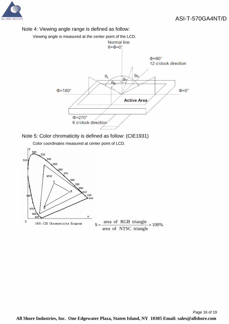
Note 4: Viewing angle range is defined as follow:
Viewing angle is measured at the center point of the LCD.
Note 5: Color chromaticity is defined as follow:
(CIE1931)
Color coordinates measured at center point of LCD.
100%triangleNTSCofarea
triangleRGBofareaS ×=
All Shore Industries, Inc. One Edgewater Plaza, Staten Island, NY 10305 Email: [email protected]
ASI-T-570GA4NT/D

Page 17 of 19
Note 6: Luminance is defined as follow: Luminance is defined as the brightness of all pixels “White” at the center of display area on optimum contrast. Note 7: Luminance Uniformity is defined as follow:
Active area is divided into 9 measuring areas (Refer Fig. 2). Every measuring point is placed at the center of each measuring area.
points 9in )brightnessLuminance( Maximumpoints 9in )brightnessLuminance( Minimum= (U)Uniformity
Fig. 2 Definition of uniformity
All Shore Industries, Inc. One Edgewater Plaza, Staten Island, NY 10305 Email: [email protected]
ASI-T-570GA4NT/D

Page 18 of 19
10. Environmental / Reliability Tests
No
Test Item
Condition
Judgment criteria
1
High Temp Operation
Ts=+70℃, 240hrs
Per table in below
2
Low Temp Operation
Ta=-20℃, 240hrs
Per table in below
3
High Temp Storage
Ta=+80℃, 240hrs
Per table in below
4
Low Temp Storage
Ta=-30℃, 240hrs
Per table in below
5 High Temp & High
Humidity
Operation Test
Ta=+40℃, 90% RH
240 hours
Per table in below
(polarizer discoloration is
excluded)
6
Thermal Cycling
(Non-operation) -30°C →
+25°C →
+80°C,200 Cycles
30 min 5min 30 min
Per table in below
7
ESD (Operation)
150pF,330Ω
Air:±
12KV;Contact: ±6KV
10 times/point;4 points/panel face Per table in below
8
Vibration (Non-operation)
Frequency:0 ~ 55 Hz Amplitude:1.5 mm
Sweep Time:11min
Test Period:6 Cycles for each Direction of
X,Y,Z
Per table in below
INSPECTION
CRITERION(after test)
Appearance
No Crack on the FPC, on the LCD Panel
Alignment of LCD
Panel
No Bubbles in the LCD Panel
No other Defects of Alignment in Active area
Electrical current
Within device specifications
Function / Display
No Broken Circuit, No Short Circuit or No Black line
No Other Defects of Display
All Shore Industries, Inc. One Edgewater Plaza, Staten Island, NY 10305 Email: [email protected]
ASI-T-570GA4NT/D

Page 19 of 19
11. Precautions for Use of LCD Modules 11.1 Safety
The liquid crystal in the LCD is poisonous. Do not put it in your mouth. If the liquid crystal touches your skin or clothes, wash it off immediately using soap and water.
11.2 Handling A. The LCD and touch panel is made of plate glass. Do not subject the panel to mechanical shock or to excessive force on its surface. B. Do not handle the product by holding the flexible pattern portion in order to assure the reliability C. Transparency is an important factor for the touch panel. Please wear clear finger sacks, gloves and mask to protect the touch panel from finger print or stain and also hold the portion outside the view area when handling the touch panel. D. Provide a space so that the panel does not come into contact with other components. E. To protect the product from external force, put a covering lens (acrylic board or similar board) and keep an appropriate gap between them. F. Transparent electrodes may be disconnected if the panel is used under environmental conditions where dew condensation occurs. G. Property of semiconductor devices may be affected when they are exposed to light, possibly resulting in IC malfunctions. H. To prevent such IC malfunctions, your design and mounting layout shall be done in the way that the IC is not exposed to light in actual use.
11.3 Static Electricity A. Ground soldering iron tips, tools and testers when they are in operation. B. Ground your body when handling the products. C. Power on the LCD module before applying the voltage to the input terminals. D. Do not apply voltage which exceeds the absolute maximum rating. E. Store the products in an anti-electrostatic bag or container.
11.4Storage A. Store the products in a dark place at +25℃±10℃ with low humidity (40% RH to 60% RH). Don't expose to sunlight or fluorescent light. B. Storage in a clean environment, free from dust, active gas, and solvent.
11.5 Cleaning A. Do not wipe the touch panel with dry cloth, as it may cause scratch. B. Wipe off the stain on the product by using soft cloth moistened with ethanol. Do not allow ethanol to get in between the upper film and the bottom glass. It may cause peeling issue or defective operation. Do not use any organic solvent or detergent other than ethanol.
11.6 Cautions for installing and assembling Bezel edge must be positioned in the area between the Active area and View area. The bezel may press the touch screen and cause activation if the edge touches the active area. A gap of approximately 0.5mm is needed between the bezel and the top electrode. It may cause unexpected activation if the gap is too narrow. There is a tolerance of 0.2 to 0.3mm for the outside dimensions of the touch panel and tail. A gap must be made to absorb the
tolerance in the case and connector.
All Shore Industries, Inc. One Edgewater Plaza, Staten Island, NY 10305 Email: [email protected]
ASI-T-570GA4NT/D