A multi-criteria approach for sustainable mass customisation in the fashion supply chain
Upload
khangminh22Category
view
0download
0
minerals
Article
“Zero-Waste”: A Sustainable Approach onPyrometallurgical Processing of ManganeseNodule Slags
Marcus Sommerfeld 1,* , David Friedmann 1, Thomas Kuhn 2 and Bernd Friedrich 1
1 Department of Process Metallurgy and Metal Recycling (IME), RWTH Aachen University, Intzestraße 3,D-52056 Aachen, Germany; [email protected] (D.F.); [email protected] (B.F.)
2 Federal Institute for Geosciences and Natural Resources (BGR), Stilleweg 2, D-30655 Hannover, Germany;[email protected]
* Correspondence: [email protected]; Tel.: +49-241-80-95-200
Received: 19 September 2018; Accepted: 17 November 2018; Published: 23 November 2018 �����������������
Abstract: A continuously growing demand for valuable non-ferrous metals and therefore an increasein their prices at the metal exchanges makes it necessary and profitable to investigate alternative metalresources. Polymetallic deep-sea nodules contain cobalt, copper, manganese, molybdenum and nickel,and are highly abundant on the sea floor. Developing a metallurgical process to recover the metalcontent from manganese nodules can close the predicted supply gap of critical metals like cobalt.This paper investigated a potential extraction process for valuable metals from manganese nodulessupplied by the German Federal Institute for Geosciences and Natural Resources. The samplesoriginated from the German license area of the Clarion-Clipperton Zone in the Pacific Ocean. Due to alow concentration of valuable metals in nodules, a pyrometallurgical enrichment step was carried outto separate cobalt, copper, molybdenum and nickel in a metallic phase. The manganese was discardedin the slag and recovered in a second smelting step as ferromanganese. To aid the experiments,FactSageTM was used for thermodynamic modeling of the smelting steps. To increase metal yieldsand to alter the composition of the metal alloys, different fluxes were investigated. The final slagafter two reduction steps were heavy-metal free and a utilization as a mineral product was desired toensure a zero-waste process.
Keywords: marine mineral resources; manganese nodules; pyrometallurgical treatment; zero-wasteprocessing; direct slag reduction; thermodynamic modeling
1. Introduction
The exploration of polymetallic deep-sea nodules as a multi-metallic resource is an ongoingresearch object since the first extensive exploration phase in the 1960s and 1970s. Due to an increasein metal prices and a continuously high demand for various metals, another extensive phase ofexploration started at the beginning of this century. Several governmental and semi-governmentalinstitutions signed contracts with the International Seabed Authority to investigate polymetallicdeep-sea nodules and since 2010 private enterprises have also done so. The most promising areafor exploitation of this marine resource is the Clarion-Clipperton Fracture Zone (CZZ) in the PacificOcean [1]. Around 15 kg of manganese nodules per square meter on average cover the seafloor in anarea the size of five million square kilometers [2].
Metals of interest in deep-sea nodules are especially copper, cobalt and nickel. Due to thehigh abundance of nodules on the deep-sea floor, the reserves for those metals are significant [3,4].Furthermore, the recovery of manganese, molybdenum and vanadium is of interest or at least the
Minerals 2018, 8, 544; doi:10.3390/min8120544 www.mdpi.com/journal/minerals
Minerals 2018, 8, 544 2 of 13
enrichment of a marketable by-product can add value to an extraction process [3]. Table 1 showsa comparison of estimated reserves for the mentioned valuable metals in manganese nodules andin land-based ore bodies, which highlights why manganese nodules are an interesting potentialresource [4].
Table 1. Comparison of the estimated resources for metals in manganese nodules in theClarion-Clipperton Fracture Zone (CCZ) and the land-based reserve base (million metric tons) [4].
Resource Co Cu Mn Mo Ni
Nodules in CCZ 42 224 5929 12 278Global land-based 13 1300 5200 19 150
The expected resources of cobalt, manganese and nickel in manganese nodules solely in the CCZsurpass the reserves of those metals on land [4]. Due to the abundance of high-grade manganese oreon land, utilizing the nodules as a source of copper and nickel only is of interest [5]. A process thatadditionally recovers cobalt is desirable due to the criticality of cobalt and its importance in the areaof clean energy technology [6]. More than one half of global cobalt mine production currently comesfrom the Democratic Republic of the Congo and since the predicted consumption increases faster thanthe world cobalt refinery capacity, a limited supply is expected. Most cobalt is already mined as aby-product of nickel and copper production [7], therefore the recovery of cobalt while extracting nickeland copper from manganese nodules can be considered a viable option to close the forecasted supplygap. A rising demand is also predicted for manganese alloys, however, metallurgical grade ores onland are distributed more evenly than cobalt [8], which minimizes a supply risk. To optimize theprofitability of a metallurgical process and to decrease the mass of produced by-products with low orno economic value, the production of marketable manganese alloys seems to be an apparent necessityto utilize manganese-rich streams.
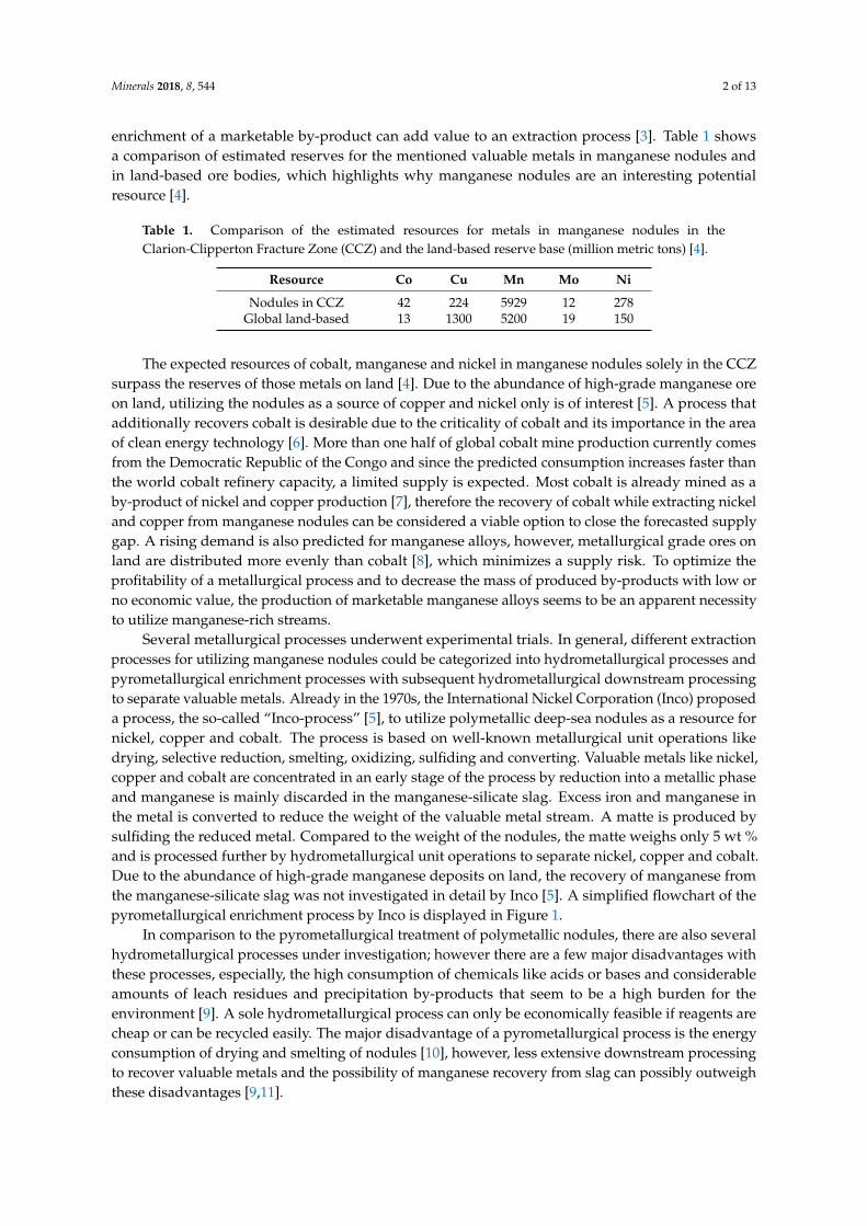
Several metallurgical processes underwent experimental trials. In general, different extractionprocesses for utilizing manganese nodules could be categorized into hydrometallurgical processes andpyrometallurgical enrichment processes with subsequent hydrometallurgical downstream processingto separate valuable metals. Already in the 1970s, the International Nickel Corporation (Inco) proposeda process, the so-called “Inco-process” [5], to utilize polymetallic deep-sea nodules as a resource fornickel, copper and cobalt. The process is based on well-known metallurgical unit operations likedrying, selective reduction, smelting, oxidizing, sulfiding and converting. Valuable metals like nickel,copper and cobalt are concentrated in an early stage of the process by reduction into a metallic phaseand manganese is mainly discarded in the manganese-silicate slag. Excess iron and manganese inthe metal is converted to reduce the weight of the valuable metal stream. A matte is produced bysulfiding the reduced metal. Compared to the weight of the nodules, the matte weighs only 5 wt %and is processed further by hydrometallurgical unit operations to separate nickel, copper and cobalt.Due to the abundance of high-grade manganese deposits on land, the recovery of manganese fromthe manganese-silicate slag was not investigated in detail by Inco [5]. A simplified flowchart of thepyrometallurgical enrichment process by Inco is displayed in Figure 1.
In comparison to the pyrometallurgical treatment of polymetallic nodules, there are also severalhydrometallurgical processes under investigation; however there are a few major disadvantages withthese processes, especially, the high consumption of chemicals like acids or bases and considerableamounts of leach residues and precipitation by-products that seem to be a high burden for theenvironment [9]. A sole hydrometallurgical process can only be economically feasible if reagents arecheap or can be recycled easily. The major disadvantage of a pyrometallurgical process is the energyconsumption of drying and smelting of nodules [10], however, less extensive downstream processingto recover valuable metals and the possibility of manganese recovery from slag can possibly outweighthese disadvantages [9,11].
Minerals 2018, 8, 544 3 of 13Minerals 2018, 8, x FOR PEER REVIEW 3 of 13
Figure 1. Simplified flowchart of the pyrometallurgical Inco-process [5].
The aim of this study was to investigate the smelting reduction operation from the Inco-process. Inco proposed a smelting reduction operation without the addition of fluxes [5]. However, to decrease the liquidus temperature and to improve the recovery of metals, the addition of fluxes can be beneficial [3]. Previous research explored the option of adding silica [3,12] or silica and lime [13]. To alter the smelting behavior and to increase the degree of reduction for valuable metals, this paper explored the usage of different additives and variations in the added amount of fluxes to the nodules. To support the design of the experimental trials FactSageTM 7.0 was used. FactSageTM is a thermochemical modeling program [14]. In this article liquidus temperatures of smelting operations, activities of oxides, degree of reduction and the composition of phases like slag or alloys were predicted by FactSageTM.
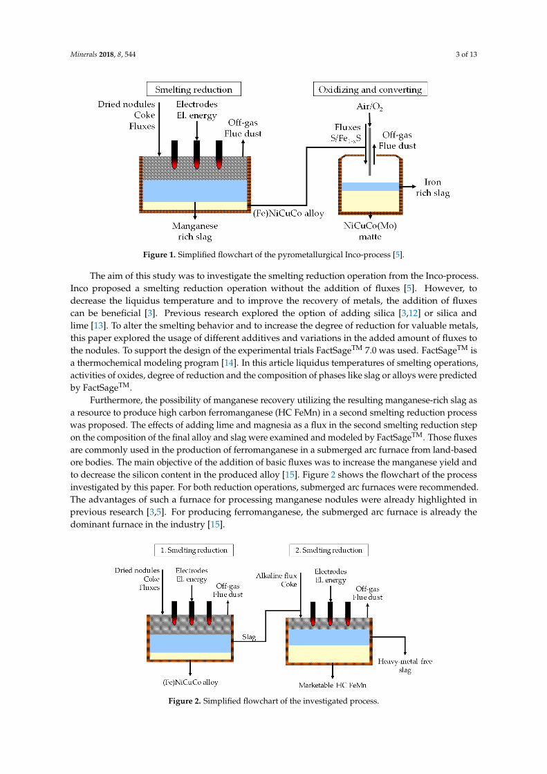
Furthermore, the possibility of manganese recovery utilizing the resulting manganese-rich slag as a resource to produce high carbon ferromanganese (HC FeMn) in a second smelting reduction process was proposed. The effects of adding lime and magnesia as a flux in the second smelting reduction step on the composition of the final alloy and slag were examined and modeled by FactSageTM. Those fluxes are commonly used in the production of ferromanganese in a submerged arc furnace from land-based ore bodies. The main objective of the addition of basic fluxes was to increase the manganese yield and to decrease the silicon content in the produced alloy [15]. Figure 2 shows the flowchart of the process investigated by this paper. For both reduction operations, submerged arc furnaces were recommended. The advantages of such a furnace for processing manganese nodules were already highlighted in previous research [3,5]. For producing ferromanganese, the submerged arc furnace is already the dominant furnace in the industry [15].
Figure 2. Simplified flowchart of the investigated process.
Figure 1. Simplified flowchart of the pyrometallurgical Inco-process [5].
The aim of this study was to investigate the smelting reduction operation from the Inco-process.Inco proposed a smelting reduction operation without the addition of fluxes [5]. However, todecrease the liquidus temperature and to improve the recovery of metals, the addition of fluxescan be beneficial [3]. Previous research explored the option of adding silica [3,12] or silica andlime [13]. To alter the smelting behavior and to increase the degree of reduction for valuable metals,this paper explored the usage of different additives and variations in the added amount of fluxes tothe nodules. To support the design of the experimental trials FactSageTM 7.0 was used. FactSageTM isa thermochemical modeling program [14]. In this article liquidus temperatures of smelting operations,activities of oxides, degree of reduction and the composition of phases like slag or alloys were predictedby FactSageTM.
Furthermore, the possibility of manganese recovery utilizing the resulting manganese-rich slag asa resource to produce high carbon ferromanganese (HC FeMn) in a second smelting reduction processwas proposed. The effects of adding lime and magnesia as a flux in the second smelting reduction stepon the composition of the final alloy and slag were examined and modeled by FactSageTM. Those fluxesare commonly used in the production of ferromanganese in a submerged arc furnace from land-basedore bodies. The main objective of the addition of basic fluxes was to increase the manganese yield andto decrease the silicon content in the produced alloy [15]. Figure 2 shows the flowchart of the processinvestigated by this paper. For both reduction operations, submerged arc furnaces were recommended.The advantages of such a furnace for processing manganese nodules were already highlighted inprevious research [3,5]. For producing ferromanganese, the submerged arc furnace is already thedominant furnace in the industry [15].
Minerals 2018, 8, x FOR PEER REVIEW 3 of 13
Figure 1. Simplified flowchart of the pyrometallurgical Inco-process [5].
The aim of this study was to investigate the smelting reduction operation from the Inco-process. Inco proposed a smelting reduction operation without the addition of fluxes [5]. However, to decrease the liquidus temperature and to improve the recovery of metals, the addition of fluxes can be beneficial [3]. Previous research explored the option of adding silica [3,12] or silica and lime [13]. To alter the smelting behavior and to increase the degree of reduction for valuable metals, this paper explored the usage of different additives and variations in the added amount of fluxes to the nodules. To support the design of the experimental trials FactSageTM 7.0 was used. FactSageTM is a thermochemical modeling program [14]. In this article liquidus temperatures of smelting operations, activities of oxides, degree of reduction and the composition of phases like slag or alloys were predicted by FactSageTM.
Furthermore, the possibility of manganese recovery utilizing the resulting manganese-rich slag as a resource to produce high carbon ferromanganese (HC FeMn) in a second smelting reduction process was proposed. The effects of adding lime and magnesia as a flux in the second smelting reduction step on the composition of the final alloy and slag were examined and modeled by FactSageTM. Those fluxes are commonly used in the production of ferromanganese in a submerged arc furnace from land-based ore bodies. The main objective of the addition of basic fluxes was to increase the manganese yield and to decrease the silicon content in the produced alloy [15]. Figure 2 shows the flowchart of the process investigated by this paper. For both reduction operations, submerged arc furnaces were recommended. The advantages of such a furnace for processing manganese nodules were already highlighted in previous research [3,5]. For producing ferromanganese, the submerged arc furnace is already the dominant furnace in the industry [15].
Figure 2. Simplified flowchart of the investigated process. Figure 2. Simplified flowchart of the investigated process.
Minerals 2018, 8, 544 4 of 13
By combining two smelting reduction processes, the following advantages were expected:
• Valuable metals are concentrated in an alloy in the first reduction step, to minimizehydrometallurgical downstream processing.
• By production of marketable ferromanganese, value can be added to the entire production process.• After two reduction processes, it is envisaged to generate a heavy-metal free slag, which can be
used as a construction material to avoid landfilling of slag and therefore reduce the burden onthe environment.
2. Thermochemistry
2.1. Thermochemistry of Manganese Nodule Smelting
The purpose of the first reduction step in Figure 2 is to discard manganese in the slag and toenrich the valuable metals in an alloy, to simplify further downstream processing [5]. For a successfulslagging operation, the activity of the oxide that should stay in the slag has to be low. A componentwith a high activity has the tendency to leave the system [16], for example by reduction and dissolvingin a metallic phase in this case. For manganese(II) oxide, this can be expressed by Equation (1):
MnO(l) + C(s) Mn(l) + CO(g) (1)
where (s) denotes components in a solid state; (l) denotes components in a liquid state; and (g) denotescomponents in gaseous state.
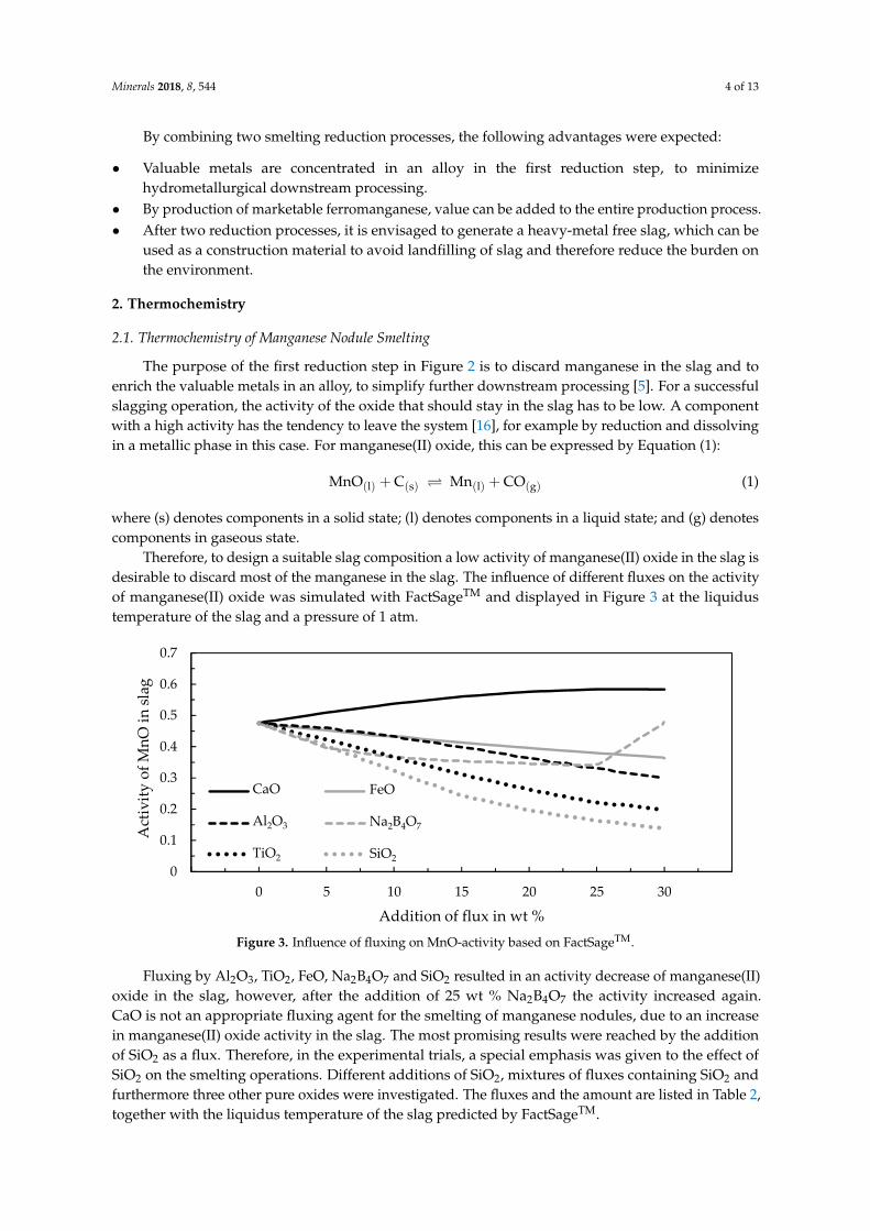
Therefore, to design a suitable slag composition a low activity of manganese(II) oxide in the slag isdesirable to discard most of the manganese in the slag. The influence of different fluxes on the activityof manganese(II) oxide was simulated with FactSageTM and displayed in Figure 3 at the liquidustemperature of the slag and a pressure of 1 atm.
Minerals 2018, 8, x FOR PEER REVIEW 4 of 13
By combining two smelting reduction processes, the following advantages were expected:
• Valuable metals are concentrated in an alloy in the first reduction step, to minimize hydrometallurgical downstream processing.
• By production of marketable ferromanganese, value can be added to the entire production process.
• After two reduction processes, it is envisaged to generate a heavy-metal free slag, which can be used as a construction material to avoid landfilling of slag and therefore reduce the burden on the environment.
2. Thermochemistry
2.1. Thermochemistry of Manganese Nodule Smelting
The purpose of the first reduction step in Figure 2 is to discard manganese in the slag and to enrich the valuable metals in an alloy, to simplify further downstream processing [5]. For a successful slagging operation, the activity of the oxide that should stay in the slag has to be low. A component with a high activity has the tendency to leave the system [16], for example by reduction and dissolving in a metallic phase in this case. For manganese(II) oxide, this can be expressed by Equation (1):
MnO(l) + C(s) ⇌ Mn(l) + CO(g) (1)
Where (s) denotes components in a solid state; (l) denotes components in a liquid state; and (g) denotes components in gaseous state.
Therefore, to design a suitable slag composition a low activity of manganese(II) oxide in the slag is desirable to discard most of the manganese in the slag. The influence of different fluxes on the activity of manganese(II) oxide was simulated with FactSageTM and displayed in Figure 3 at the liquidus temperature of the slag and a pressure of 1 atm.
Figure 3. Influence of fluxing on MnO-activity based on FactSageTM.
Fluxing by Al2O3, TiO2, FeO, Na2B4O7 and SiO2 resulted in an activity decrease of manganese(II) oxide in the slag, however, after the addition of 25 wt % Na2B4O7 the activity increased again. CaO is not an appropriate fluxing agent for the smelting of manganese nodules, due to an increase in manganese(II) oxide activity in the slag. The most promising results were reached by the addition of SiO2 as a flux. Therefore, in the experimental trials, a special emphasis was given to the effect of SiO2 on the smelting operations. Different additions of SiO2, mixtures of fluxes containing SiO2 and furthermore three other pure oxides were investigated. The fluxes and the amount are listed in Table 2, together with the liquidus temperature of the slag predicted by FactSageTM.
0
0.1
0.2
0.3
0.4
0.5
0.6
0.7
-5 0 5 10 15 20 25 30 35
Act
ivity
of M
nO in
slag
Addition of flux in wt %
CaO
Al2O3
TiO2
FeO
Na2B4O7
SiO2
Figure 3. Influence of fluxing on MnO-activity based on FactSageTM.
Fluxing by Al2O3, TiO2, FeO, Na2B4O7 and SiO2 resulted in an activity decrease of manganese(II)oxide in the slag, however, after the addition of 25 wt % Na2B4O7 the activity increased again.CaO is not an appropriate fluxing agent for the smelting of manganese nodules, due to an increasein manganese(II) oxide activity in the slag. The most promising results were reached by the additionof SiO2 as a flux. Therefore, in the experimental trials, a special emphasis was given to the effect ofSiO2 on the smelting operations. Different additions of SiO2, mixtures of fluxes containing SiO2 andfurthermore three other pure oxides were investigated. The fluxes and the amount are listed in Table 2,together with the liquidus temperature of the slag predicted by FactSageTM.
Minerals 2018, 8, 544 5 of 13
Table 2. Effect of flux on liquidus temperature and basicity, modeled with FactSageTM forsmelting nodules.
Fluxing No Addition 15% SiO2 25% SiO230%
SiO2-CaO20% SiO2-TiO2,
10% Al2O325% TiO2
20%Na2B4O7
20% Fe2O3
TLiq in ◦C 1514 1263 1285 1365 1190 1204 1302 1403
Mixtures of components were equimolar; additions were in wt %.
2.2. Thermochemistry of Ferromanganese Production
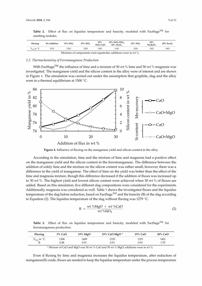
With FactSageTM the influence of lime and a mixture of 50 wt % lime and 50 wt % magnesia wasinvestigated. The manganese yield and the silicon content in the alloy were of interest and are shownin Figure 4. The simulation was carried out under the assumption that graphite, slag and the alloywere in a thermal equilibrium at 1500 ◦C.
Minerals 2018, 8, x FOR PEER REVIEW 5 of 13
Table 2. Effect of flux on liquidus temperature and basicity, modeled with FactSageTM for smelting nodules.
Fluxing No
Addition 15% SiO2
25% SiO2
30% SiO2-CaO
20% SiO2-TiO2, 10% Al2O3
25% TiO2
20% Na2B4O7
20% Fe2O3
TLiq in °C
1514 1263 1285 1365 1190 1204 1302 1403
Mixtures of components were equimolar; additions were in wt %.
2.2. Thermochemistry of Ferromanganese Production
With FactSageTM the influence of lime and a mixture of 50 wt % lime and 50 wt % magnesia was investigated. The manganese yield and the silicon content in the alloy were of interest and are shown in Figure 4. The simulation was carried out under the assumption that graphite, slag and the alloy were in a thermal equilibrium at 1500 °C.
Figure 4. Influence of fluxing on the manganese yield and silicon content in the alloy.
According to the simulation, lime and the mixture of lime and magnesia had a positive effect on the manganese yield and the silicon content in the ferromanganese. The difference between the addition of solely lime and the mixture on the silicon content was rather small, however, there was a difference in the yield of manganese. The effect of lime on the yield was better than the effect of the lime and magnesia mixture, though this difference decreased if the addition of fluxes was increased up to 30 wt %. The highest yield and lowest silicon content were achieved when 30 wt % of fluxes are added. Based on this simulation, five different slag compositions were considered for the experiments. Additionally, magnesia was considered as well. Table 3 shows the investigated fluxes and the liquidus temperature of the slag before reduction, based on FactSageTM and the basicity (B) of the slag according to Equation (2). The liquidus temperature of the slag without fluxing was 1279 °C.
B = wt %MgO + wt %CaO
wt %SiO2 (2)
Table 3. Effect of flux on liquidus temperature and basicity, modeled with FactSageTM for ferromanganese production.
Fluxing 5% CaO 15% MgO 15% CaO-MgO * 15% CaO 30% CaO TLiq in °C 1308 1409 1335 1351 1401
B 0.48 0.91 0.91 0.91 1.55 * Mixture of CaO and MgO was 50 wt % CaO and 50 wt % MgO; additions were in wt %.
0
2
4
6
8
10
74
76
78
80
82
84
0 10 20 30
Silic
on co
nten
t in
wt %
Man
gane
se y
ield
in %
Addition of flux in wt %
CaO
CaO+MgO
CaO
CaO+MgOSi-c
onte
ntM
n-re
cove
ry
Figure 4. Influence of fluxing on the manganese yield and silicon content in the alloy.
According to the simulation, lime and the mixture of lime and magnesia had a positive effecton the manganese yield and the silicon content in the ferromanganese. The difference between theaddition of solely lime and the mixture on the silicon content was rather small, however, there was adifference in the yield of manganese. The effect of lime on the yield was better than the effect of thelime and magnesia mixture, though this difference decreased if the addition of fluxes was increased upto 30 wt %. The highest yield and lowest silicon content were achieved when 30 wt % of fluxes areadded. Based on this simulation, five different slag compositions were considered for the experiments.Additionally, magnesia was considered as well. Table 3 shows the investigated fluxes and the liquidustemperature of the slag before reduction, based on FactSageTM and the basicity (B) of the slag accordingto Equation (2). The liquidus temperature of the slag without fluxing was 1279 ◦C.
B =wt %MgO + wt %CaO
wt %SiO2(2)
Table 3. Effect of flux on liquidus temperature and basicity, modeled with FactSageTM forferromanganese production.
Fluxing 5% CaO 15% MgO 15% CaO-MgO * 15% CaO 30% CaO
TLiq in ◦C 1308 1409 1335 1351 1401B 0.48 0.91 0.91 0.91 1.55
* Mixture of CaO and MgO was 50 wt % CaO and 50 wt % MgO; additions were in wt %.
Even if fluxing by lime and magnesia increases the liquidus temperature, after reduction ofmanganese(II) oxide, fluxes are needed to keep the liquidus temperature under the process temperature
Minerals 2018, 8, 544 6 of 13
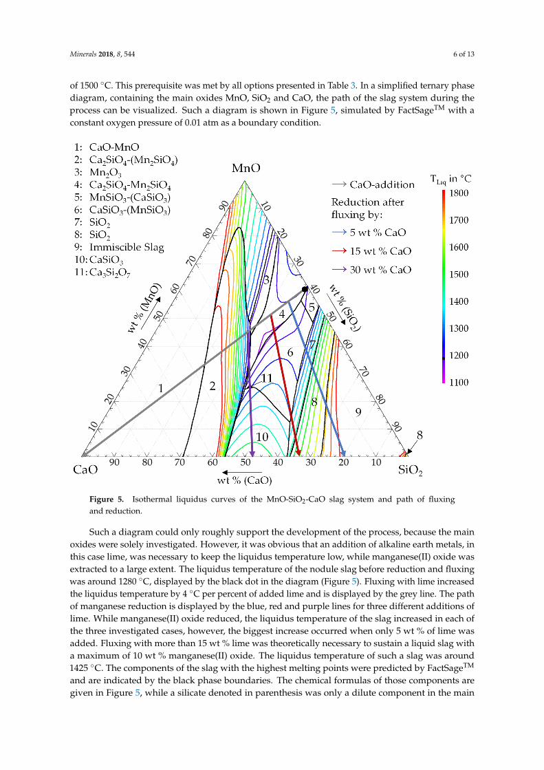
of 1500 ◦C. This prerequisite was met by all options presented in Table 3. In a simplified ternary phasediagram, containing the main oxides MnO, SiO2 and CaO, the path of the slag system during theprocess can be visualized. Such a diagram is shown in Figure 5, simulated by FactSageTM with aconstant oxygen pressure of 0.01 atm as a boundary condition.
Minerals 2018, 8, x FOR PEER REVIEW 6 of 13
Even if fluxing by lime and magnesia increases the liquidus temperature, after reduction of manganese(II) oxide, fluxes are needed to keep the liquidus temperature under the process temperature of 1500 °C. This prerequisite was met by all options presented in Table 3. In a simplified ternary phase diagram, containing the main oxides MnO, SiO2 and CaO, the path of the slag system during the process can be visualized. Such a diagram is shown in Figure 5, simulated by FactSageTM with a constant oxygen pressure of 0.01 atm as a boundary condition.
Figure 5. Isothermal liquidus curves of the MnO-SiO2-CaO slag system and path of fluxing and reduction.
Such a diagram could only roughly support the development of the process, because the main oxides were solely investigated. However, it was obvious that an addition of alkaline earth metals, in this case lime, was necessary to keep the liquidus temperature low, while manganese(II) oxide was extracted to a large extent. The liquidus temperature of the nodule slag before reduction and fluxing was around 1280 °C, displayed by the black dot in the diagram (Figure 5). Fluxing with lime increased the liquidus temperature by 4 °C per percent of added lime and is displayed by the grey line. The path of manganese reduction is displayed by the blue, red and purple lines for three different additions of lime. While manganese(II) oxide reduced, the liquidus temperature of the slag increased in each of the three investigated cases, however, the biggest increase occurred when only 5 wt % of lime was added. Fluxing with more than 15 wt % lime was theoretically necessary to sustain a liquid slag with a maximum of 10 wt % manganese(II) oxide. The liquidus temperature of such a slag was around 1425 °C. The components of the slag with the highest melting points were predicted by FactSageTM and are indicated by the black phase boundaries. The chemical formulas of those components are given in Figure 5, while a silicate denoted in parenthesis was only a dilute component
Figure 5. Isothermal liquidus curves of the MnO-SiO2-CaO slag system and path of fluxingand reduction.
Such a diagram could only roughly support the development of the process, because the mainoxides were solely investigated. However, it was obvious that an addition of alkaline earth metals, inthis case lime, was necessary to keep the liquidus temperature low, while manganese(II) oxide wasextracted to a large extent. The liquidus temperature of the nodule slag before reduction and fluxingwas around 1280 ◦C, displayed by the black dot in the diagram (Figure 5). Fluxing with lime increasedthe liquidus temperature by 4 ◦C per percent of added lime and is displayed by the grey line. The pathof manganese reduction is displayed by the blue, red and purple lines for three different additions oflime. While manganese(II) oxide reduced, the liquidus temperature of the slag increased in each ofthe three investigated cases, however, the biggest increase occurred when only 5 wt % of lime wasadded. Fluxing with more than 15 wt % lime was theoretically necessary to sustain a liquid slag witha maximum of 10 wt % manganese(II) oxide. The liquidus temperature of such a slag was around1425 ◦C. The components of the slag with the highest melting points were predicted by FactSageTM
and are indicated by the black phase boundaries. The chemical formulas of those components aregiven in Figure 5, while a silicate denoted in parenthesis was only a dilute component in the main
Minerals 2018, 8, 544 7 of 13
silicate. A detailed description and the names of the phases in the FactSageTM database are listedin Table S1 of the Supplementary Information. Silicon oxides was the component with the highestmelting point for trials with low additions of lime and calcium silicates having the highest meltingpoint in the trials with more than 15 wt % additional lime.
3. Materials and Experimental Details
3.1. Smelting of Manganese Nodules
The deep-sea nodules studied in this research were a common sample from the German licensearea in the CCZ. The average chemical content of the valuable metals is presented in Table 4 [3].
Table 4. Average chemical content of valuable metals in dried deep-sea nodules from the German licensearea in the Clarion-Clipperton Fracture Zone (CCZ), analyzed by ICP-OES and ICP-MS (wt %) [3].
Co Cu Mn Mo Ni V
0.16 1.17 31.2 0.06 1.36 0.06
The manganese nodules were dried before the analysis, because they contained significantamounts of water. In addition to physically bound moisture, water of hydration was present in thenodules. The loss on ignition of dried nodules was still around 15 wt %. The initial ratio of MnO toSiO2 in the measured samples was 3.2 [3].
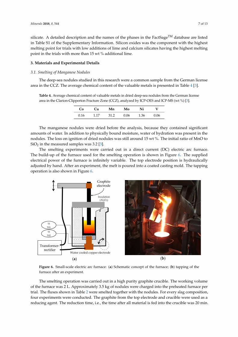
The smelting experiments were carried out in a direct current (DC) electric arc furnace.The build-up of the furnace used for the smelting operation is shown in Figure 6. The suppliedelectrical power of the furnace is infinitely variable. The top electrode position is hydraulicallyadjusted by hand. After an experiment, the melt is poured into a coated casting mold. The tappingoperation is also shown in Figure 6.
Minerals 2018, 8, x FOR PEER REVIEW 7 of 13
in the main silicate. A detailed description and the names of the phases in the FactSageTM database are listed in Table S1 of the Supplementary Information. Silicon oxides was the component with the highest melting point for trials with low additions of lime and calcium silicates having the highest melting point in the trials with more than 15 wt % additional lime.
3. Materials and Experimental Details
3.1. Smelting of Manganese Nodules
The deep-sea nodules studied in this research were a common sample from the German license area in the CCZ. The average chemical content of the valuable metals is presented in Table 4 [3].
Table 4. Average chemical content of valuable metals in dried deep-sea nodules from the German license area in the Clarion-Clipperton Fracture Zone (CCZ), analyzed by ICP-OES and ICP-MS (wt %) [3].
Co Cu Mn Mo Ni V 0.16 1.17 31.2 0.06 1.36 0.06
The manganese nodules were dried before the analysis, because they contained significant amounts of water. In addition to physically bound moisture, water of hydration was present in the nodules. The loss on ignition of dried nodules was still around 15 wt %. The initial ratio of MnO to SiO2 in the measured samples was 3.2 [3].
The smelting experiments were carried out in a direct current (DC) electric arc furnace. The build-up of the furnace used for the smelting operation is shown in Figure 6. The supplied electrical power of the furnace is infinitely variable. The top electrode position is hydraulically adjusted by hand. After an experiment, the melt is poured into a coated casting mold. The tapping operation is also shown in Figure 6.
(a)
(b)
Figure 6. Small-scale electric arc furnace: (a) Schematic concept of the furnace; (b) tapping of the furnace after an experiment.
The smelting operation was carried out in a high purity graphite crucible. The working volume of the furnace was 2 L. Approximately 3.5 kg of nodules were charged into the preheated furnace per trial. The fluxes shown in Table 2 were smelted together with the nodules. For every slag composition, four experiments were conducted. The graphite from the top electrode and crucible were used as a reducing agent. The reduction time, i.e., the time after all material is fed into the crucible was 20 min. The reduction temperature was about 150 °C above the modeled liquidus temperature of the slag (Table 2).
Transformer-rectifier
TIT01
TIT02
Graphite electrode
Water cooled copper electrode
Insulation(Al2O3)
Figure 6. Small-scale electric arc furnace: (a) Schematic concept of the furnace; (b) tapping of thefurnace after an experiment.
The smelting operation was carried out in a high purity graphite crucible. The working volumeof the furnace was 2 L. Approximately 3.5 kg of nodules were charged into the preheated furnace pertrial. The fluxes shown in Table 2 were smelted together with the nodules. For every slag composition,four experiments were conducted. The graphite from the top electrode and crucible were used as areducing agent. The reduction time, i.e., the time after all material is fed into the crucible was 20 min.

Minerals 2018, 8, 544 8 of 13
The reduction temperature was about 150 ◦C above the modeled liquidus temperature of the slag(Table 2).
To verify the most promising results and to generate enough homogeneous material for theinvestigation of ferromanganese production, a second furnace was used to increase the mass ofsmelted nodules per experiment. The scale-up furnace is similar to the furnace in Figure 6, but 8 kgof nodules could be smelted per trial. The working volume of the furnace was 6 L. Six trials werecarried out in this furnace and 48 kg of nodules were smelted in total. The temperature of the slagduring the reduction time was 1400 ◦C and the reduction time was increased to 60 min, due to theincreased mass of nodules. To provide sufficient reducing agent, 200 g of carbon in the form of cokewith a particle size between 1–5 mm was added per trial further to the carbon supply from the crucibleand top electrode. After the reduction time, all coke reacted with the slag and gas.
Generated slag in this paper was analyzed by fused cast bead X-ray fluorescence spectroscopy(XRF) and the metal by a wavelength dispersive X-ray fluorescence spectroscopy (WDXRF)spectrometer. The carbon content in the metal was determined by an infrared absorption method aftercombustion in an induction furnace. The mass of the metallic phase and the slag was measured witha scale.
3.2. Smelting of Manganese-Rich Slag
The homogenized, crushed and screened manganese-bearing slag from the scale-up experimentswas used for the production of ferromanganese following the process shown in Figure 2. For thesmelting of manganese-rich slag, the small-scale electric arc furnace was used. 3 kg of slag wassmelted together with fluxes in each experiment. The five combinations of fluxes shown in Table 3were investigated. Every experiment was carried out twice. The smelting temperature was 1500 ◦C.The reducing agent for the production of ferromanganese was the graphite from the crucible and topelectrode as well. Furthermore, 6.2 wt % carbon was additionally added in the form of coke with aparticle size between 1–5 mm. The reduction time was 60 min, after this time all coke had reacted withthe slag and gas.
4. Results and Discussion
4.1. Smelting of Manganese Nodules
To determine the efficiency of the smelting operation, the yield was calculated by usingEquation (3):
ηx= 100% ·mxMetal
mxMetal + mxSlag
(3)
where ηx was the yield of element x; mxMetal was the mass of the element x in the metal; and mxSlag
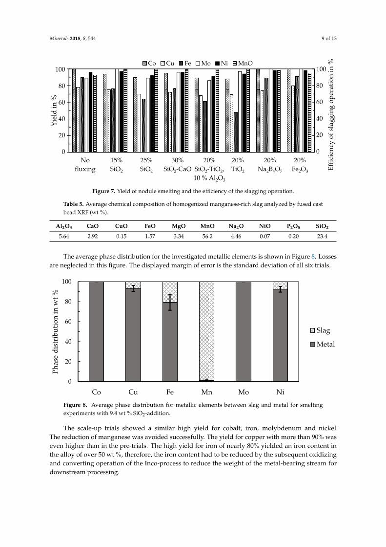
was the mass of the element x in the slag. The mass of an element in a single phase was calculatedwith information about the total mass of the phase and the concentration of the element in that phase.The yield for the valuable metals and iron are shown in Figure 7 for the experiments in the furnace witha volume of 2 L. To determine the efficiency of the slagging operation for manganese, the reciprocalvalue of the fraction from Equation (3) was displayed.
Due to the high manganese content in the slag and high yields for valuable metals, fluxing withNa2B4O7 or SiO2 seemed to be beneficial. However, Na2B4O7 is rather costly compared to SiO2,therefore only SiO2 was considered a viable option for a process on an industrial scale. In the trials,the addition of 15 wt % SiO2 showed an advantage over the addition of 25 wt % SiO2 and the mixturescontaining SiO2 and other fluxes.
Based on the results in Figure 7, six scale-up trials were conducted. Compared to the small-scaletrials, the SiO2-addition decreased to 9.4 wt %. The average chemical composition of the main oxidesin the slag is shown in Table 5.
Minerals 2018, 8, 544 9 of 13
Minerals 2018, 8, x FOR PEER REVIEW 9 of 13
Figure 7. Yield of nodule smelting and the efficiency of the slagging operation.
Due to the high manganese content in the slag and high yields for valuable metals, fluxing with Na2B4O7 or SiO2 seemed to be beneficial. However, Na2B4O7 is rather costly compared to SiO2, therefore only SiO2 was considered a viable option for a process on an industrial scale. In the trials, the addition of 15 wt % SiO2 showed an advantage over the addition of 25 wt % SiO2 and the mixtures containing SiO2 and other fluxes.
Based on the results in Figure 7, six scale-up trials were conducted. Compared to the small-scale trials, the SiO2-addition decreased to 9.4 wt %. The average chemical composition of the main oxides in the slag is shown in Table 5.
Table 5. Average chemical composition of homogenized manganese-rich slag analyzed by fused cast bead XRF (wt %).
Al2O3 CaO CuO FeO MgO MnO Na2O NiO P2O5 SiO2 5.64 2.92 0.15 1.57 3.34 56.2 4.46 0.07 0.20 23.4
The average phase distribution for the investigated metallic elements is shown in Figure 8. Losses are neglected in this figure. The displayed margin of error is the standard deviation of all six trials.
Figure 8. Average phase distribution for metallic elements between slag and metal for smelting experiments with 9.4 wt % SiO2-addition.
The scale-up trials showed a similar high yield for cobalt, iron, molybdenum and nickel. The reduction of manganese was avoided successfully. The yield for copper with more than 90% was
0
20
40
60
80
100
0
20
40
60
80
100
No fluxing 15 % SiO2 25 % SiO230 % SiO2-CaO20 % SiO2-TiO2, 10 % Al2O325 % TiO220 % Na2B4O720 % Fe2O3
Yiel
d in
%Co Cu Fe Mo Ni MnO
Nofluxing
15%SiO2
25%SiO2
30%SiO2-CaO
20%SiO2-TiO2,10 % Al2O3
20%TiO2
20%Na2B4O7
20%Fe2O3
100
80
60
40
20
0
100
80
60
40
20
0
Yiel
d in
%
Effic
ienc
y of
slag
ging
ope
ratio
n in
%
0
20
40
60
80
100
Co Cu Fe Mn Mo Ni
Phas
e di
stri
butio
n in
wt %
Slag
Metal
Figure 7. Yield of nodule smelting and the efficiency of the slagging operation.
Table 5. Average chemical composition of homogenized manganese-rich slag analyzed by fused castbead XRF (wt %).
Al2O3 CaO CuO FeO MgO MnO Na2O NiO P2O5 SiO2
5.64 2.92 0.15 1.57 3.34 56.2 4.46 0.07 0.20 23.4
The average phase distribution for the investigated metallic elements is shown in Figure 8. Lossesare neglected in this figure. The displayed margin of error is the standard deviation of all six trials.
Minerals 2018, 8, x FOR PEER REVIEW 9 of 13
Figure 7. Yield of nodule smelting and the efficiency of the slagging operation.
Due to the high manganese content in the slag and high yields for valuable metals, fluxing with Na2B4O7 or SiO2 seemed to be beneficial. However, Na2B4O7 is rather costly compared to SiO2, therefore only SiO2 was considered a viable option for a process on an industrial scale. In the trials, the addition of 15 wt % SiO2 showed an advantage over the addition of 25 wt % SiO2 and the mixtures containing SiO2 and other fluxes.
Based on the results in Figure 7, six scale-up trials were conducted. Compared to the small-scale trials, the SiO2-addition decreased to 9.4 wt %. The average chemical composition of the main oxides in the slag is shown in Table 5.
Table 5. Average chemical composition of homogenized manganese-rich slag analyzed by fused cast bead XRF (wt %).
Al2O3 CaO CuO FeO MgO MnO Na2O NiO P2O5 SiO2 5.64 2.92 0.15 1.57 3.34 56.2 4.46 0.07 0.20 23.4
The average phase distribution for the investigated metallic elements is shown in Figure 8. Losses are neglected in this figure. The displayed margin of error is the standard deviation of all six trials.
Figure 8. Average phase distribution for metallic elements between slag and metal for smelting experiments with 9.4 wt % SiO2-addition.
The scale-up trials showed a similar high yield for cobalt, iron, molybdenum and nickel. The reduction of manganese was avoided successfully. The yield for copper with more than 90% was
0
20
40
60
80
100
0
20
40
60
80
100
No fluxing 15 % SiO2 25 % SiO230 % SiO2-CaO20 % SiO2-TiO2, 10 % Al2O325 % TiO220 % Na2B4O720 % Fe2O3
Yiel
d in
%
Co Cu Fe Mo Ni MnO
Nofluxing
15%SiO2
25%SiO2
30%SiO2-CaO
20%SiO2-TiO2,10 % Al2O3
20%TiO2
20%Na2B4O7
20%Fe2O3
100
80
60
40
20
0
100
80
60
40
20
0
Yiel
d in
%
Effic
ienc
y of
slag
ging
ope
ratio
n in
%
0
20
40
60
80
100
Co Cu Fe Mn Mo Ni
Phas
e di
stri
butio
n in
wt %
Slag
Metal
Figure 8. Average phase distribution for metallic elements between slag and metal for smeltingexperiments with 9.4 wt % SiO2-addition.
The scale-up trials showed a similar high yield for cobalt, iron, molybdenum and nickel.The reduction of manganese was avoided successfully. The yield for copper with more than 90% waseven higher than in the pre-trials. The high yield for iron of nearly 80% yielded an iron content inthe alloy of over 50 wt %, therefore, the iron content had to be reduced by the subsequent oxidizingand converting operation of the Inco-process to reduce the weight of the metal-bearing stream fordownstream processing.
Minerals 2018, 8, 544 10 of 13
4.2. Smelting of Manganese-Rich Slag
4.2.1. Analysis of Ferromanganese
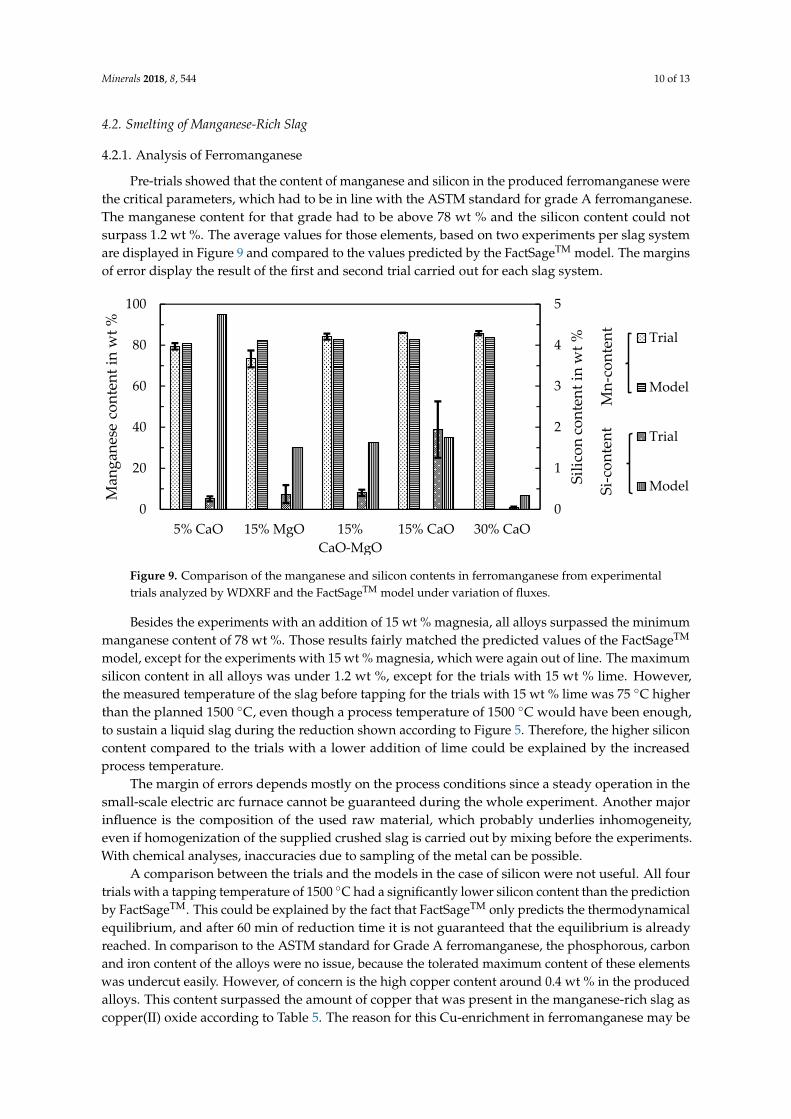
Pre-trials showed that the content of manganese and silicon in the produced ferromanganese werethe critical parameters, which had to be in line with the ASTM standard for grade A ferromanganese.The manganese content for that grade had to be above 78 wt % and the silicon content could notsurpass 1.2 wt %. The average values for those elements, based on two experiments per slag systemare displayed in Figure 9 and compared to the values predicted by the FactSageTM model. The marginsof error display the result of the first and second trial carried out for each slag system.
Minerals 2018, 8, x FOR PEER REVIEW 10 of 13
even higher than in the pre-trials. The high yield for iron of nearly 80% yielded an iron content in the alloy of over 50 wt %, therefore, the iron content had to be reduced by the subsequent oxidizing and converting operation of the Inco-process to reduce the weight of the metal-bearing stream for downstream processing.
4.2. Smelting of Manganese-rich Slag
4.2.1. Analysis of Ferromanganese
Pre-trials showed that the content of manganese and silicon in the produced ferromanganese were the critical parameters, which had to be in line with the ASTM standard for grade A ferromanganese. The manganese content for that grade had to be above 78 wt % and the silicon content could not surpass 1.2 wt %. The average values for those elements, based on two experiments per slag system are displayed in Figure 9 and compared to the values predicted by the FactSageTM model. The margins of error display the result of the first and second trial carried out for each slag system.
Figure 9. Comparison of the manganese and silicon contents in ferromanganese from experimental trials analyzed by WDXRF and the FactSageTM model under variation of fluxes.
Besides the experiments with an addition of 15 wt % magnesia, all alloys surpassed the minimum manganese content of 78 wt %. Those results fairly matched the predicted values of the FactSageTM model, except for the experiments with 15 wt % magnesia, which were again out of line. The maximum silicon content in all alloys was under 1.2 wt %, except for the trials with 15 wt % lime. However, the measured temperature of the slag before tapping for the trials with 15 wt % lime was 75 °C higher than the planned 1500 °C, even though a process temperature of 1500 °C would have been enough, to sustain a liquid slag during the reduction shown according to Figure 5. Therefore, the higher silicon content compared to the trials with a lower addition of lime could be explained by the increased process temperature.
The margin of errors depends mostly on the process conditions since a steady operation in the small-scale electric arc furnace cannot be guaranteed during the whole experiment. Another major influence is the composition of the used raw material, which probably underlies inhomogeneity, even if homogenization of the supplied crushed slag is carried out by mixing before the experiments. With chemical analyses, inaccuracies due to sampling of the metal can be possible.
A comparison between the trials and the models in the case of silicon were not useful. All four trials with a tapping temperature of 1500 °C had a significantly lower silicon content than the prediction by FactSageTM. This could be explained by the fact that FactSageTM only predicts the thermodynamical equilibrium, and after 60 min of reduction time it is not guaranteed that the equilibrium is already reached. In comparison to the ASTM standard for Grade A ferromanganese,
0
1
2
3
4
5
0
20
40
60
80
100
5% CaO 15% MgO 15%CaO-MgO
15% CaO 30% CaO
Silic
on co
nten
t in
wt %
Man
gane
se c
onte
nt in
wt % Trial
Model
Trial
ModelSi-c
onte
ntM
n-co
nten
t
Figure 9. Comparison of the manganese and silicon contents in ferromanganese from experimentaltrials analyzed by WDXRF and the FactSageTM model under variation of fluxes.
Besides the experiments with an addition of 15 wt % magnesia, all alloys surpassed the minimummanganese content of 78 wt %. Those results fairly matched the predicted values of the FactSageTM
model, except for the experiments with 15 wt % magnesia, which were again out of line. The maximumsilicon content in all alloys was under 1.2 wt %, except for the trials with 15 wt % lime. However,the measured temperature of the slag before tapping for the trials with 15 wt % lime was 75 ◦C higherthan the planned 1500 ◦C, even though a process temperature of 1500 ◦C would have been enough,to sustain a liquid slag during the reduction shown according to Figure 5. Therefore, the higher siliconcontent compared to the trials with a lower addition of lime could be explained by the increasedprocess temperature.
The margin of errors depends mostly on the process conditions since a steady operation in thesmall-scale electric arc furnace cannot be guaranteed during the whole experiment. Another majorinfluence is the composition of the used raw material, which probably underlies inhomogeneity,even if homogenization of the supplied crushed slag is carried out by mixing before the experiments.With chemical analyses, inaccuracies due to sampling of the metal can be possible.
A comparison between the trials and the models in the case of silicon were not useful. All fourtrials with a tapping temperature of 1500 ◦C had a significantly lower silicon content than the predictionby FactSageTM. This could be explained by the fact that FactSageTM only predicts the thermodynamicalequilibrium, and after 60 min of reduction time it is not guaranteed that the equilibrium is alreadyreached. In comparison to the ASTM standard for Grade A ferromanganese, the phosphorous, carbonand iron content of the alloys were no issue, because the tolerated maximum content of these elementswas undercut easily. However, of concern is the high copper content around 0.4 wt % in the producedalloys. This content surpassed the amount of copper that was present in the manganese-rich slag ascopper(II) oxide according to Table 5. The reason for this Cu-enrichment in ferromanganese may be

Minerals 2018, 8, 544 11 of 13
due to copper-rich metal droplets, which have still been in the charged nodule slag. Even if the slag iscrushed and screened before the experiments, it can be possible, that small droplets remained in theslag and contaminated the ferromanganese. By improving the metal and slag phase separation a lowercopper content could be possible.
4.2.2. Analysis of the Final Slag
The final slag was analyzed and FactSageTM was used to model the liquidus temperature afterthe experiments. The basicity was again calculated by Equation (2). Table 6 shows the basicity andliquidus temperature for the investigated slags.
Table 6. Basicity and liquidus temperature of the final slag modeled with FactSageTM.
Fluxing 5% CaO 15% MgO 15% CaO-MgO 15% CaO 30% CaO
TLiq in ◦C 1312 1470 1357 1203 1284B 0.44 0.83 0.83 0.83 1.19
Magnesia seemed to not be useful in the process since the liquidus temperature was only 30 ◦Clower than the proposed process temperature and as discussed before, the manganese content in theproduced alloy was insufficient. Therefore, lime only seems to be an option for fluxing, an addition of5–15 wt % is recommended. The liquidus temperature was low enough to ensure a liquid slag duringthe process and the produced alloys were in line with the ASTM standard. Fluxing with 30 wt % limewas not recommended because of two reasons, (i) the usage of so much flux is uneconomical and (ii)the slag of the experiments with 30 wt % lime tends to disintegrate, which prohibits the use of the slagas a mineral product in the construction industry.
For the development of a zero-waste process the final slag has to be a usable product. The contentof heavy metals in the final slag should be as low as possible (Table 7).
Table 7. Amount of heavy metal traces in the final slag analyzed by fused cast bead XRF (wt %).
Fluxing 5% CaO 15% MgO 15% CaO-MgO 15% CaO 30% CaO
Cr2O3 <0.01 <0.01 <0.01 <0.01 <0.01CuO 0.11 0.04 0.05 0.03 0.03NiO 0.09 0.01 0.02 0.01 <0.01V2O5 0.05 <0.01 0.01 <0.01 <0.01
The results showed that the concentration of most of the heavy metals in the slag was alreadylow. The highest concentration was 0.11 wt % for copper(II) oxide in one sample. Nevertheless, only aleaching test can prove if the slag fulfills the requirements for a heavy-metal free slag, accordingto regulations.
5. Conclusions
This paper investigated the pyrometallurgical enrichment process of valuable metals frommanganese nodules and explored the utilization of the manganese-bearing slag.
Pre-trials and further scale-up experiments highlighted the beneficial effects of fluxing by SiO2
in the smelting reduction process of manganese nodules. Optimal parameters were a smeltingtemperature of 1400 ◦C and the addition of 9.4 wt % SiO2 to recover over 90% and up to 100%of cobalt, copper, molybdenum, nickel and manganese was successfully discarded into the slag to asignificant extent (>97%). The enrichment of valuable metals in an alloy while discarding gangue andmanganese with the slag is an advantage of the process, since it significantly reduces the amount ofmaterial, which needs to be processed further by hydrometallurgical methods.
Minerals 2018, 8, 544 12 of 13
The trials to produce ferromanganese showed that the manganese-bearing slag could be usedas a resource to produce an alloy that conformed with the ASTM standard. Recovering manganeseas a marketable alloy has two significant advantages, (i) the generation of revenue and (ii) by furtherreduction the total amount of slag is decreased and heavy-metals are reduced and collected in themetal, which is relevant for utilizing the slag as a mineral product, for example in the constructionindustry. Different fluxes and the amount of added fluxes were investigated. The results showed thatthe addition of 5–15 wt % of lime provided the best results. However, further studies and a scale-upare necessary especially for the second reduction step. Copper impurities are another problem inthe alloy, which make further investigation of the copper behavior during the reduction and phaseseparation necessary. Furthermore, the utilization of the resulting slag as a mineral product has to beproven in supplementary studies, however, the chemical analysis does not show elevated contents forheavy-metals and is therefore promising.
Supplementary Materials: The following are available online at http://www.mdpi.com/2075-163X/8/12/544/s1, Table S1: Description of occurring phases from the phase diagram (Figure 5).
Author Contributions: M.S. designed, carried out and analyzed the ferromanganese experiments. D.F. designed,carried out and analyzed the manganese nodules smelting experiments. M.S. wrote the paper with significantcontributions from T.K. and B.F. All authors read and approved the final manuscript.
Funding: This research was funded by internal BGR funding under the grant number A-0203002.A.
Acknowledgments: The German Federal Institute for Geosciences and Natural Resources (BGR) is acknowledgedfor the supply of raw nodules, financial and additional support.
Conflicts of Interest: The funding sponsors had no role in the design of the study; in the collection, analyses, orinterpretation of data; and in the decision to publish the results. As part of the funding sponsor, T.K. contributedto writing the manuscript.
References
1. Rühlemann, C.; Knodt, S. Manganese nodule exploration & exploitation from the deep ocean. J. Ocean Technol.2015, 10, 13–21.
2. Hein, J.R.; Petersen, S. The geology of manganese nodules. In Deep Sea Minerals: Manganese Nodules,a Physical, Biological, Environmental and Technical Review; Beaudoin, Y.C., Baker, E., Eds.; Secretariat of thePacific Community: Nouméa, New Caledonia, 2013; pp. 7–18. ISBN 978-82-7701-120-2.
3. Friedmann, D.; Pophanken, A.K.; Friedrich, B. Pyrometallurgical treatment of high manganese containingdeep sea nodules. J. Sustain. Metal. 2017, 3, 219–229. [CrossRef]
4. Hein, J.R.; Koschinsky, A. Deep-ocean ferromanganese crusts and nodules. In Treatise on Geochemistry,2nd ed.; Holland, H.D., Turekian, K., Eds.; Elsevier: Amsterdam, The Netherlands, 2014; pp. 273–291,ISBN 978-0-08-098300-4.
5. Sridhar, R.; Jones, W.E.; Warner, J.S. Extraction of copper, nickel and cobalt from sea nodules. J. Miner. Met.Mater. Soc. 1976, 28, 32–37. [CrossRef]
6. Grandell, L.; Lehtilä, A.; Kivinen, M.; Koljonen, T.; Kihlman, S.; Lauri, L.S. Role of critical metals in the futuremarkets of clean energy technologies. Renew. Energy 2016, 95, 53–62. [CrossRef]
7. United States Geological Survey. Mineral Commodity Summaries–Cobalt 2018. Available online: https://minerals.usgs.gov/minerals/pubs/commodity/cobalt/mcs-2018-cobal.pdf (accessed on 24 May 2018).
8. United States Geological Survey. Minerals Yearbook—Manganese 2014. Available online: https://minerals.usgs.gov/minerals/pubs/commodity/manganese/myb1-2014-manga.pdf (accessed on 14 September 2017).
9. Premchand, P.; Jana, R.K. Processing of polymetallic sea nodules: An overview. In Proceedings of the ThirdISOPE Ocean Mining Symposium, Goa, India, 8–10 November 1999; International Society of Offshore andPolar Engineers: Cupertino, CA, USA, 1999; pp. 237–245.
10. Agarwal, J.C.; Beecher, N.; Davies, D.S.; Hubred, G.L.; Kakaria, V.K.; Kust, R.N. Processing of ocean nodules:A technical and economic review. J. Miner. Met. Mater. Soc. 1976, 28, 24–31. [CrossRef]
11. Sen, P.K. Metals and materials from deep sea nodules: An outlook for the future. Int. Mater. Rev. 2013, 55,364–391. [CrossRef]
Minerals 2018, 8, 544 13 of 13
12. Sahu, K.K.; Agarwal, S.; Mishra, D.; Agrawal, A.; Randhawa, N.S.; Godiwalla, K.M.; Jana, R.K. Nickel,cobalt and copper recovery from sea nodules by direct smelting process. In Proceedings of the Ni-Co 2013,San Antonio, TX, USA, 3–7 March 2013; Battle, T., Moats, M., Cocalia, V., Oosterhof, H., Alam, S., Eds.;Springer: Cham, Switzerland, 2013; pp. 291–298.
13. Kohga, T.; Imamura, M.; Takahashi, J.; Tanaka, N.; Nishizawa, T. Recovering iron, manganese, copper, cobalt,and high-purity nickel from sea nodules. J. Miner. Met. Mater. Soc. 1995, 47, 40–43. [CrossRef]
14. Bale, C.C.; Bélisle, E.; Chartrand, P.; Decterov, S.A.; Eriksson, G.; Gheribi, A.; Hack, K.; Jung, I.-H.;Melançon, J.; Pelton, A.D.; et al. Recent developments in Factsage thermochemical software and databases.In Celebrating the Megascale, Proceedings of the Extraction and Processing Division Symposium on Pyrometallurgy inHonor of David G.C. Robertson, San Diego, CA, USA, 16–20 February 2014; Mackey, P.J., Grimsey, E.J., Jones, R.T.,Brooks, G.A., Eds.; Springer: Cham, Switzerland, 2014; pp. 141–148.
15. Olsen, S.E.; Tangstad, M.; Lindstad, T. Production of Manganese Ferroalloys; Tapir Akademisk Forlag:Trondheim, Norway, 2007; ISBN 978-82-519-2191-6.
16. Coudurier, L.; Hopkins, D.W.; Wilkomirsky, I. Fundamentals of Metallurgical Processes, 2nd ed.; Pergamon Press:Oxford, UK, 1985; ISBN 978-0-08-032536-1.
© 2018 by the authors. Licensee MDPI, Basel, Switzerland. This article is an open accessarticle distributed under the terms and conditions of the Creative Commons Attribution(CC BY) license (http://creativecommons.org/licenses/by/4.0/).
Copyright © 2022 FDOKUMEN