a study on stern wedges and advanced spray rail system on ...
10
(J) (D 2(D A STUDY ON STERN WEDGES AND ADVANCED SPRAY RAIL SYSTEM ON CALM WATER RESISTANCE OF HIGH-SPEED DISPLACEMENT HULL FORMS Q) - Predrag Bojovic Prasanta K Sahoo Marcos Salas ABS Americas Department of Maritime Engineering Faculty of Engineering Sciences O [6885 Northchase Drive Australian Maritime College, PO Box 986 University Austral of Chile ° ouston, TX 77060, USA Launceston, TAS 7250, Australia Casilla 567, Valdivia, Chile [email protected] P. [email protected] [email protected] ABSTRACT The first part of the research presented was published in the proceedings of Sea Australia 2000 (Bojovic and Sahoo 2000), which presented the results of the tests of model #13 with stern wedges, with and without spray rails. The wedges were faired into the hull surface at the bilges and had O 4 70 and 100 angles relative to the hull surface. Two pairs of spray rails were fitted based on the Advanced Spray Rails System, described by Muller-Graf (1991). The research presented in this paper was performed with spray rails and included additional wedge angle tests on model #13, together with a set of tests with increased wedge length (3% instead of 2% Lpp). In addition, models #05 and #09 were tested with spray rails and wedge length of 2% over the range of wedge angles and speeds. The test results demonstrated very valuable benefits available from stern wedge fitting to this type of vessel. They are presented together with the results of the analysis. The effect of wedge angle variation is discussed and a mathematical model was developed and implemented as the performance prediction sojh.vare. The effect of wedge length variation is also discussed. 1 INTRODUCTION 1.1 BACKGROUND The systematic series of high-speed displacement hull forms is obtained from two parent hulls by systematic variation of three hull form parameters - LIB, B/T and CB. The series' parameter space with the fourteen models built to date is presented in Figure 1. 1.2 TESTING OUTLINE The results of earlier work regarding the application of spray rails and stern wedges have been described Bojovic and Sahoo (2000). That work contains the literature review, reasons leading to stem wedge tests rather than trim tabs ones, descriptions of testing procedure, stern wedge configuration, spray rails geometry and test results. Table 1 presents the test matrix for the set of tests carried out with model #13. These tests clearly demonstrated significant benefits available from the installation of stem wedges, as the CR reduction was in excess of 10% for Fn above 0.4. A larger decrease of
-
Upload
khangminh22 -
Category
Documents
-
view
1 -
download
0
Transcript of a study on stern wedges and advanced spray rail system on ...

(J)(D 2(D
A STUDY ON STERN WEDGES AND ADVANCED SPRAY RAILSYSTEM ON CALM WATER RESISTANCE OF HIGH-SPEED
DISPLACEMENT HULL FORMSQ)
- Predrag Bojovic Prasanta K Sahoo Marcos SalasABS Americas Department of Maritime Engineering Faculty of Engineering Sciences
O [6885 Northchase Drive Australian Maritime College, PO Box 986 University Austral of Chile° ouston, TX 77060, USA Launceston, TAS 7250, Australia Casilla 567, Valdivia, [email protected] P. [email protected] [email protected]
ABSTRACT
The first part of the research presented was published in the proceedings ofSea Australia2000 (Bojovic and Sahoo 2000), which presented the results of the tests of model #13 withstern wedges, with and without spray rails. The wedges were faired into the hull surface atthe bilges and had O 4 70 and 100 angles relative to the hull surface. Two pairs of sprayrails were fitted based on the Advanced Spray Rails System, described by Muller-Graf(1991).
The research presented in this paper was performed with spray rails and included additionalwedge angle tests on model #13, together with a set of tests with increased wedge length (3%
instead of 2% Lpp). In addition, models #05 and #09 were tested with spray rails andwedge length of 2% over the range of wedge angles and speeds. The test resultsdemonstrated very valuable benefits available from stern wedge fitting to this type of vessel.They are presented together with the results of the analysis. The effect of wedge anglevariation is discussed and a mathematical model was developed and implemented as theperformance prediction sojh.vare. The effect of wedge length variation is also discussed.
1 INTRODUCTION
1.1 BACKGROUND
The systematic series of high-speed displacement hull forms is obtained from two parenthulls by systematic variation of three hull form parameters - LIB, B/T and CB. The series'parameter space with the fourteen models built to date is presented in Figure 1.
1.2 TESTING OUTLINE
The results of earlier work regarding the application of spray rails and stern wedges havebeen described Bojovic and Sahoo (2000). That work contains the literature review, reasonsleading to stem wedge tests rather than trim tabs ones, descriptions of testing procedure, sternwedge configuration, spray rails geometry and test results. Table 1 presents the test matrix forthe set of tests carried out with model #13.
These tests clearly demonstrated significant benefits available from the installation of stemwedges, as the CR reduction was in excess of 10% for Fn above 0.4. A larger decrease of

residuary resistance was achieved at higher wedge angles, indicating that the optimum wedgeangle was greater than 10°. Another look at the literature, Muller-Graf (1991), found thattests in the Berlin Model Basin also didn't reach the optimum wedge angle with wedge anglesup to 10°, as can be seen from Figure 2.
Table 1: Test matrix for model #13 tests
jp
w
ua
Figure 1: AME CRC Systematic SeriesParameter Space
10--
op30
30
40-
I I:--
-10---1--t-- I I ¿
-20- Wd9e L*nQth LW - 0.02133 LWL
t I I I
T T T 1 T rl I 6« Weg inçUnationI I l.pnd 6,() I IT1t wthSR2
---.2] 14 vIthASR$
i-.-(SRisR2) -f- - -- LWL/BWL 6.25
1 Hufi without pendcg t - 1 - - -I I I I I
:-t .-irT-\ II I I J I I
0.9 1.0Fri - 1.2
Figure 2: Change of Residual Resistance due to the ASRS (MuIler-Graf, 1991)
The early test results were found very valuable and provided the motivation to extend theresearch work to greater wedge angles. Also, it was decided to test two other series' models,with different L/B ratios, since the literature, Millward (1976), suggests that the LIB ratioinfluences benefits from stern wedge installation. For that purpose it was decided to testrebuilt models #05 and #09. From Figure 1 it can be seen that the three models tested (#05,#13 and #09) lay on the "diagonal" of the systematic series parameter space. Their bodyplans are presented in Figure 3 and their particulars in Table 2.
Wedge angle WithoutSpray Rails
WithSprayRails
0° V V
4° V /70 V V100 V V
0.80.2 0.3 0.4 0.5 06 0.7Rfer*ncs HuH: without Spray RaR.f.r.es Surfoo.: w.tted Stjrfac. at R.t
The earlier tests didn't find explicit benefits from spray rail installation. However, it wasdecided to continue performing tests with them, as ITTC (1984) suggests that semi-displacement round-bilge hulls should be tested with spray rails, in order to avoid substantialincrease of the wetted surface area, which could reach 50 to 60% of the wetted surface area atrest.
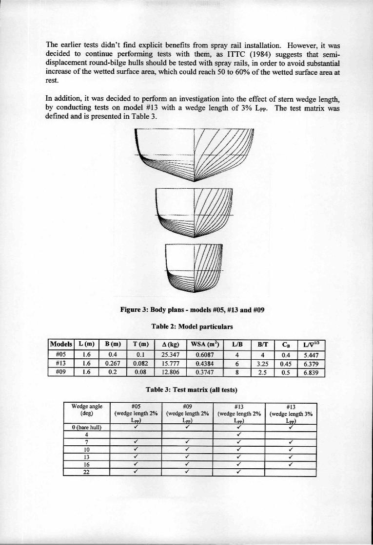
In addition, it was decided to perform an investigation into the effect of stern wedge length,by conducting tests on model #13 with a wedge length of 3% The test matrix wasdefined and is presented in Table 3.
Figure 3: Body plans - models #05, #13 and #09
Table 2: Model particulars
Table 3: Test matrix (all tests)
Models L (m) B (m) T (m) (kg) WSA (m2) L/B BIT CB L/V'#05 1.6 0.4 0.1 25.347 0.6087 4 4 0.4 5.447#13 1.6 0.267 0.082 15.777 0.4384 6 3.25 0.45 6.379#09 1.6 0.2 0.08 12.806 0.3747 8 2.5 0.5 6.839
Wedge angle(deg)
#05(wedge length 2%
L)#09
(wedge length 2%Lp)
#13(wedge length 2%
L)#13
(wedge length 3%L)
O (bare hull)4 17 / Vf Vf
IO / /13 1 / /16 /22 / "

The initial test data analysis performed during and immediately after the testing, concludedthat the research outcomes would significantly benefit from an additional set of data for awedge angle of 22°. Therefore, an extra set of test for 22° wedges (on all three models) wasorganised and performed, at the test speeds listed in Table 4.
Table 4: Tested speeds
2 RESULTS
2.1 TEST DATA
Test results were analysed according to the standard procedure, by subtracting the frictionalresistance, calculated according to the ITTC 1957 ship-model correlation line, from the totalresistance. The residuary resistance was made non-dimensional using the standard formula,Equation 1:
RI?CR
2
All tests were performed at the standard displacement, outlined in Table 2, and analysedusing the wetted surface area for the bare hull, as it was assumed that the presence of the sternwedge did not significantly change the wetted surface area.
As expected, the test results of increasing wedge angles followed the trend of resistancedecrease up to a certain wedge angle, above which an increase of resistance occurred. Inorder to define the influence of the wedge angle variation on the model's performance at theparticular tested speed, quadratic parabolas were fitted to the test data. This was performedusing the standard least-squares technique, Kreyszig (1988).
2.2 EFFECT OF WEDGE ANGLE
As mentioned above, the stern wedge installation benefits occur only above Fn 0.4. Belowthis speed a performance decrease occurs. This performance decrease may be a result of sternflaps scaling effects. It is known that the flow conditions around the model stern flap aresomewhat different from those on the ship. Actual performance of full-scale prototype sternflaps during trials have exceeded their model test predictions, exhibiting no negative effectsat lower speeds caused by increased transom immersion due to stern wedge presence. At Fnof around 0.40, the residuary resistance of the hull with the wedge is level with the bare hullresiduary resistance. Consequently, above this speed performance improvement occurs. Itcan be seen that a significant decrease of residuary resistance could be achieved with sternwedge installation and the existence of an optimum wedge angle can be seen from these plots.
The results are summarised in Figures 4 and 5. When the installation of a stern wedge (of agiven length) is considered for a particular design, there are usually two questions that needto be answered: "what is the optimum wedge (angle)?" and "what are the benefits from theoptimum wedge?" Figures 4 and 5 answer those questions. From Figure 4 it can be seen that
(1)
Speed(m/s) 0.6 0.9 1.2 1.3 1.4 1.7 1.9 2 2.1 2.4 2.7 3 3.3Fn 0.15 0.23 0.3 0.33 0.35 0.43 0.48 0.5 0.53 0.61 0.68 0.76 0.83

I
a relative consistency of trends exists, with a slight optimum wedge angle decrease withspeed. Figure 5 quantifies the benefits achievable with stern wedge installation. It alsoconfirms some literature statements, that beamier hulls obtain greater benefits from sternwedge installation, as model #05 demonstrated the highest residuary resistance reduction.
Figure 5 also illustrates an interesting fact, that the shorter wedge on model #13 is moreefficient than the longer one, at speeds up to approximately Fn 0.73.
Another practical question regarding wedge sizing could be 'how sensitive are wedgebenefits to the deviation from the optimum angle?" Figure 6 illustrates the effect of a wedgeangle (±) 2° different from the optimum angle. It can be seen that this variation causes lessthan 0.5% change in residuary résistance. Figure 7 illustrates the wedge angle limits, whichwould ensure residuary resistance benefits within 0.5% of the optimal.
0)a)C
0.95
E0.9
Q.o
0.85I
0.7
18
l6
E6E4Q.02
o
0.8 +#05W-#13w2o
O.75----#13w3L.
o
.#05*#13w2A--#13 w3
Figure 5: C relative to Bare Hull at the optimum Wedge Angle against Fn.
0.4 0.5 0.6 0.7 Fn 0.8 0.9 11
Figure 4: Optimum Wedge angle against Fn.
04 0.5 0.6 0.7 Fn 0.8 0.9 1 11

2.4 EFFECT OF SPRAY RAILS
The spray rails used in the tests presented here are described in Bojovic and Sahoo (2000).They are based on Advanced Spray Rail System, described in Muller-Graf (1991). That paperreports that this spray rail system when combined with the optimum stern wedge leads toremarkable power savings which are larger than the sum of the savings obtained by eachcomponent solely, with improved seakeeping qualities and reduced apparent loss ofmetacentric height at high speeds.
Figure 2 presents the results obtained in Berlin Model Basin. They show some benefitsavailable from spray rail installation only, for Fn between 0.40 and 0.90. Figure 8 presents thetest results obtained for three tested models, with and without the spray rails.
The spray rail installation benefits are the most prominent for model #05. It has the lowestLIB and L/V"3 ratios. The spray rails system contributed mostly through the rising of fore-body due to significant lift developed by the spray rails. However, the benefits from sprayrails installation only are not the focus of the research presented here, as spray rails arerecommended for testing of this type of hull.
Eo
ww
w
CswC,=wwC)
w
wC,=C,nu
C.,
E
EC-ew
0.008
0.00 7
0.006
0.005
0.0 04
0.003
0.00 2
0.001
D
-.-- #05---#13 w2-*-#13 w3)(-- #09
-....-#09
#05
#13w3A
#05e
A #13w3
04 0.5 0.6 0.7 0.8 0.9
Fn
Figure 7: Wedge angle limits for CR within ±0.5% from optimal
0 4 0.5 0.6 0.7 0.8 0.9
Fn
Figure 6: CR change at wedge angle 2° different from optimum angle

2.5 EFFECT OF WEDGE LENGTH
The sizing of the stern wedge involves selection of the wedge length and the wedge angle.While the effect of the wedge angle was tested on the three models, the effect of wedgelength variation was tested on model #13 only, with wedge lengths of 2% and 3% Lpp.
In order to visualise the results better, it was decided to use a combination of two overlapping3D surface plots, as presented in Figure 9. The vertical values represent the CR valuesrelative to the bare hull condition, as a function of Fn and wedge angle. The intersection ofthe two surfaces can be clearly seen on the left side of the figure. On the right side, theintersection curves and the "optimum-angle" curves for both surfaces are plotted as verticallyextruded surfaces. The "height" of these surfaces corresponds to 2% (or 0.02) on the plot'svertical axis. Additionally, the optimum-angle curves are presented in Figures 4 and 5.
ooo
Q
- - .. #05 without SR#05 with SR
--G--#l3withoutSR#l3withSR
- - o- - -#09 without SR#09 with SR
01 0.3 0.5 0.7 0.9
Fn
Figure 8: Test results with and without spray rails
Figure 10 presents the same surface plots, but with contour curves on them, in order to bettervisualise trends of change. These contour curves are presented in a contour plot in Figure 11.It can be seen that "the best" shorter wedge performance (at the optimum angle) provides abetter performance than "the best" longer wedge performance for Fn up to 0.7. The longerwedge is more efficient above this speed. An explanation of this could be speculated on thebasis of trade-of between wedge's induced drag and hull drag reduction due to morebeneficial vessel's trim. It is also possible that the wedge angle change is more efficient thanwedge length change in changing the vessel's trim. This deserves a further investigation,perhaps through some additional testing ofone or more models.
3 CONCLUDING REMARKS
The first part of the research identified clear benefits available from the installation of sternwedges on one of the series' models. This provoked further research into this area and thesubsequent towing tank tests explored wedge angles above 100 and the effect of wedge lengthchange. Also, two additional series' hulls were tested with 2% Lpp wedge over the range ofwedge angles and speeds. The test matrix is outlined in Table 3. The current researchpresented, analysed and discussed the results.

2% Lfr E
2% L - crrvw
0.6 67 0.1 0.9 LO
FN
Figure 11: CR relative to the bare hull- contour plot
Figure 9: CR relative to the bare hull - 2% and 3% Lpp wedge lengths
Figure 10: CR relative to the bare hull - 2% and 3% Lpp wedge lengths

The test results confirmed there are significant benefits available from stern wedgeinstallation on this type of vessel. While the results present a very reliable source of data,some additional tests would make the picture more complete. It would be beneficial to testsome additional models to identify the correlation between the wedge effects and the hullparameters. After considerable thought, the wedge effect was linked to L/V"3, while arguablyit could have been linked to L/B or some combination of the series' parameters. Theinvestigation of wedge length variation provided interesting results arid additional tests withone or more models would provide better understanding of interrelating parameters - wedgelength and wedge angle, leading to highly practical outcomes.
While the main focus of this report was in quantifying and optimising stern wedge benefits,which at model scale occur only at Fn >0.4, care was taken to enable reliable estimates of theperformance penalty below this speed. As mentioned in section 2.2 full-scale performances atlow speed might be better than the corresponding one at model scale.
On the other hand, if something could be improved, then it was not perfect in the firstinstance. While the test results presented here indicate that stern wedge should beincorporated into the design of this type of vessel, they could also be interpreted as anindication that the hull should be altered. Maybe "classic" straight aft buttocks should bemade slightly "hooked" to incorporate the wedge in a more natural way and to enable liftgeneration along a greater length. A similar approach, for hard-chine, planing vessels, wasexamined in Blount (1995). Both convex and concave aft buttocks shapes were explored.
4 ACKNOWLEDGMENTS
The authors would also like to thank the authorities of the Australian Maritime College andthe University of Austral of Chile for their continued support during the course of thisresearch work.
5 NOTATION AND ABBREVIATIONS
AMECRC Australian Maritime Engineering CRC LtdASRS Advanced Spray Rail SystemB Model beamB/T Beam-draft ratioCB Block coefficient (V / L x B x T)CG Centre of GravityCR Coefficient of residuary resistanceFn Froude number based on lengthITTC International Towing Tank ConferenceL Model lengthLIB Length-beam ratioLCG Longitudinal centre of gravity
Length between perpendicularsL/V"3, L/voV'(l/3) Length-volume ratio (slenderness) ratioT Model draught
6 REFERENCES
Bojovic, P. and Sahoo, P. (2000): "Effect of Stern Wedges and Advanced Spray Rail Systemon Calm Water Resistance of High-Speed Displacement Hull Forms", Proc. Of Sea Australia2000, Sydney, Australia.

Blount, D.L. (1995): "Factors influencing the Selection of a hard Chine or Round Bilge Hullfor High Froude Numbers", Proc. of Fast Sea Transportation 1995, pp 3-20
Miliward, A. (1976): "Effect of Wedges on the Performance Characteristics of Two PlaningHulls". Journal of Ship Research, Vol. 20, No. 4, pp. 224-232.
ITTC (1984): "A survey of Available Knowledge on the Drag Scaling of ModelAppendages", 17th IT[7'C, pp. 368-376.
Kreyszig, E. (1988): "Advanced Engineering Mathematics", Sixth Edition, John Wiley &Sons, Section 19.5, pp. 1029-1031
Muller-Graf, B. (1991): "The Effect of an Advanced Spray Rail System on Resistance andDevelopment of Spray of Semi-Displacement Round Bilge Hulls", Proc. of Fast SeaTransportation 1991,Vol. 1, pp 125-142