A study of design principles for refrigerators for low-power ...
118
NATL INST. OF STAND & TEC[ A11 1 5 TaZflfl3 \ <*** 0F c % IN ^^ J? **»EAU O* ^ NSST PUBLICATIONS NBS TECHNICAL NOTE 1049 U.S. DEPARTMENT OF COMMERCBNational Bureau of Standards
-
Upload
khangminh22 -
Category
Documents
-
view
3 -
download
0
Transcript of A study of design principles for refrigerators for low-power ...

NATL INST. OF STAND & TEC[
A 1 1 1 5 TaZflfl3
\
<*** 0F c%
IN^^ J?**»EAU O* ^
NSST
PUBLICATIONS
NBS TECHNICAL NOTE 1049
U.S. DEPARTMENT OF COMMERCBNational Bureau of Standards

NATIONAL BUREAU OF STANDARDS
The National Bureau of Standards' was established by an act of Congress on March 3, 1901.
The Bureau's overall goal is to strengthen and advance the Nation's science and technology
and facilitate their effective application for public benefit. To this end, the Bureau conducts
research and provides: (1) a basis for the Nation's physical measurement system, (2) scientific
and technological services for industry and government, (3) a technical basis for equity in
trade, and (4) technical services to promote public safety. The Bureau's technical work is per-
formed by the National Measurement Laboratory, the National Engineering Laboratory, and
the Institute for Computer Sciences and Technology.
THE NATIONAL MEASUREMENT LABORATORY provides the national system ol
physical and chemical and materials measurement; coordinates the system with measurement
systems of other nations and furnishes essential services leading to accurate and uniform
physical and chemical measurement throughout the Nation's scientific community, industry,
and commerce; conducts materials research leading to improved methods of measurement,
standards, and data on the properties of materials needed by industry, commerce, educational
institutions, and Government; provides advisory and research services to other Government
agencies; develops, produces, and distributes Standard Reference Materials; and provides
calibration services. The Laboratory consists of the following centers:
Absolute Physical Quantities' — Radiation Research — Thermodynamics and
Molecular Science — Analytical Chemistry — Materials Science.
THE NATIONAL ENGINEERING LABORATORY provides technology and technical ser-
vices to the public and private sectors to address national needs and to solve national
problems; conducts research in engineering and applied science in support of these efforts;
builds and maintains competence in the necessary disciplines required to carry out this
research and technical service; develops engineering data and measurement capabilities;
provides engineering measurement traceability services; develops test methods and proposes
engineering standards and code changes; develops and proposes new engineering practices;
and develops and improves mechanisms to transfer results of its research to the ultimate user.
The Laboratory consists of the following centers:
Applied Mathematics — Electronics and Electrical Engineering 2 — Mechanical
Engineering and Process Technology 2 — Building Technology — Fire Research —Consumer Product Technology — Field Methods.
THE INSTITUTE FOR COMPUTER SCIENCES AND TECHNOLOGY conducts
research and provides scientific and technical services to aid Federal agencies in the selection,
acquisition, application, and use of computer technology to improve effectiveness and
economy in Government operations in accordance with Public Law 89-306 (40 U.S.C. 759),
relevant Executive Orders, and other directives; carries out this mission by managing the
Federal Information Processing Standards Program, developing Federal ADP standards
guidelines, and managing Federal participation in ADP voluntary standardization activities;
provides scientific and technological advisory services and assistance to Federal agencies; and
provides the technical foundation for computer-related policies of the Federal Government.
The Institute consists of the following centers:
Programming Science and Technology — Computer Systems Engineering.
'Headquarters and Laboratories at Gaithersburg, MD, unless otherwise noted;
mailing address Washington, DC 20234.2Some divisions within the center are located at Boulder. CO 80303.
A Study of Design Principles for Refrigerators
for Low-Power Cryoelectronic Devices
J.E. ZimmermanD.B. Sullivan
Electromagnetic Technology Division
National Engineering Laboratory
National Bureau of Standards
Boulder, Colorado 80303
\ as /
U.S. DEPARTMENT OF COMMERCE, Malcolm Baldrige, Secretary
NATIONAL BUREAU OF STANDARDS. Ernest Ambler. Director
Issued January 1982

National Bureau of Standards Technical Note 1049
Nat. Bur. Stand. (U.S.), Tech. Note 1049, 114 pages (January 1982)
CODEN:NBTNAE
U.S. GOVERNMENT PRINTING OFFICEWASHINGTON: 1982

CONTENTS
Page
1. Introduction 1
2. Background
2.1 Split Stirling-Cycle 2
2.2 Twin-Piston Stirling Cycle 4
3. Summary of Refrigerator Development
3.1 Split Stirling Cycle 4
3.1.1 Materials 4
3.1.2 Construction 5
3.1.3 Operation 6
3.2 Twin-Piston Stirling Refrigerator 8
3.3 Compressor Design 8
3.3.1 '0' Ring Sealed Piston with Conventional Crosshead 8
3.3.2 Force Balanced Compressor 9
3.3.3 Contamination Free Compressor 9
3.4 Temperature Control. . 10
4. Cryocooler Optimization
4.1 General Approach 11
4.2 The Calculation 13
4.3 Results 14
5. Summary and Conclusions 17
6. References 17
7. Appendix 19
m

A Study of Design Principles for RefrigeratorsFor Low-Power Cryoelectronic Devices
J. E. Zimmerman and D. B. SullivanNational Bureau of Standards
Electromagnetic Technology DivisionBoulder, Colorado 80303
This report summarizes a five-year effort at NBS which has been directed toward thedevelopment of low-power cryocoolers suited to the support of superconducting instruments.The report deals with a variety of aspects of construction and operation of refrigerators as
well as with a model which allows one to optimize the design for minimum drive power. Thepublications generated by the program are included as an appendix.
Key words: cryocooler; cryogenics; low temperature; refrigerator; Stirling cycle; super-conducting devices.
1. Introduction
This report describes a five-year effort at NBS to develop small, low-power Stirling crycooolers
which are suited to the support of highly sensitive superconducting instrumentation, particularly
magnetometers and magnetic gradiometers based on the Superconducting Quantum Interference Device
(SQUID). The latter part of this first section describes the environmental requirements for such
instrumentation. In Section 2 we provide a brief discussion of the operation of the cryocoolers and in
Section 3 summarize the refrigerator development work. Section 4 describes a model which has been
developed to optimize cryocooler design and finally the publications generated by the program are
appended for completeness.
The new class of cryocoolers considered in this report were first described at two conferences in
the summer of 1976 [1, 2]. The machine described in these papers achieved a temperature of 13 K with
three stages. The addition of a fourth stage reduced the bottom-end temperature to less than 8.5 K and
a niobium SQUID magnetometer was operated with the cooler [3]. Analysis of the machine's operation was
reported subsequently [4, 5]. The operation of the cooler is limited by the internal thermal
resistance of the plastic regenerator components, a situation much different than that for all other
Stirling machines. In 1979, a low-pressure, twin-piston single stage cooler was built. This cooler
succeeded in cooling from temperatures in the 8 to 12 K region to a bottom end temperature of 3 to 4 K
[6]. This stage could conceivably be added to one of the higher-pressure (2 to 4 bars), multistage
machines to achieve helium temperature operation. Finally we refer to a sequence of papers [7, 8, 9,
10,] which review and update the progress on this refrigeration work. The last of these papers
describes a 5-stage refrigerator which achieves a bottom end temperature of less than 7 K with only 20
W of mechanical power input. This machine has been fitted with a small diagonal -component SQUID
gradiometer which shows, in a preliminary way, that SQUIDs and refrigerators can be successfully
integrated. For demonstration purposes this gradiometer-cooler system has produced a magnetocardiogram
of modest clarity [11]. This combination was also used to investigate the level and source of magnetic
interference generated by the cryocooler. Some preliminary work has also been done on a pulsed
technique for measuring the thermal characteristics (thermal conductivity and specific heat) of the
plastic regenerator materials used in these machines [12]. This method is useful because the usual
measurement methods are cumbersome due to the very long thermal response times for these materials.
The environmental requirements for a SQUID magnetometer are extreme and, as far as we know, no
attempt to operate a SQUID with a commercial cryocooler has been made. The expected vibration and
magnetic noise levels are so large that the SQUID output would be meaningless [13]. This is not
surprising since the SQUID has a sensitivity of the order of 10 times the earth's magnetic field.
Thus, even ignoring the direct magnetic interference from moving parts in the refrigerator, a motion of4
only one microradian in the earth's field causes an interference output which is 10 times the
sensitivity. From these figures one readily appreciates the need for vibration reduction. Low speed
and low-power operation can produce such reduction. In fact, we have taken the view that optimization
of refrigerator design for this purpose is really a minimization of the refrigerator power input. The
assumption is that the net interference will scale with the size and power requirement of the drive
machinery. The calculations in Section 4 are based on this design philosophy. Obviously, one must
also avoid the use of magnetic components and even good conductors (since motion of a conductor in a
field produces field variation through induced eddy currents). Even ostensibly non-ferro-magnetic
materials have susceptibilities and remanent moments which can be troublesome. Thus, material
selection is important. It is not essential, however, to eliminate all interference, since the major
interference component is synchronous with the drive system of the refrigerator. Synchronous filtering
can thus be used to reduce interference, but it is certainly best to start with a low level of
interference because such filtering can never be complete.
Three final points should be made. First, if refrigerators are to become important for the
support of superconducting devices, then it is essential that their complexity and cost be not much
greater than that of the devices they support. This places some sort of bound on practical solutions
to the problem. Second, there is a possibility that high-T devices can alter the situation. That is,
the cooling requirements are significantly affected by use of devices that might operate at say 10 or
15 K. Fabrication technology for these devices is not highly developed, but good devices have been
reported by several laboratories, perhaps most notably the Naval Research Laboratory. Where such
devices could be used, the size and cost of the cryocooler would be reduced significantly [14].
Finally, the feature of most commercial cryocoolers which contributes to the interference is an
unnecessarily large refrigeration capacity and drive power (of the order of kilowatts). By matching
the crycoooler capacity to the inherently low refrigeration requirements of a SQUID magnetometer, a
large reduction in drive power and direct magnetic interference from the drive train can be realized.
Cost can be reduced and portability enhanced at the same time. This is really just a restatement of
the design philosophy mentioned in the previous paragraph.
2. Background
2.1 Split Stirling-Cycle
The operation of a split Stirling-cycle refrigerator can be understood through study of figure 1.
Gas moves freely by the displacer exchanging heat with the displacer and walls as it moves between the
hot end (T,) and cold end (T~). Thus, the pressure throughout the system is nearly the same at any
instant in time. Work W = fPdV may be done on the system as the piston moves back and forth, but no
work is done by or on the displacer. When the displacer is at its lowest position, the piston is moved
to the left compressing the working fluid (helium gas) and producing heat Q-, , which is rejected at T-,.

Then the displacer is moved to the top of the cylinder so that gas is displaced from top to bottom.
Assuming that the machine has been operating for some time and the bottom temperature T« is less than
T\ , then the gas gives up heat Q, to the displacer and wall in the annular gap and arrives at theI a
bottom at a temperature Tp. The piston then moves to the right producing a heat flow Q^ into the gas
at T~. Finally, the gas is moved upward as the displacer is returned to its bottom position and a heat
Q. is added as the gas temperature goes from T~ back to T,. This completes one cycle of operation.
<ci-
T 2
REGENERATORGAP
PISTON
Absorbed
REGENERATORHEAT CAPACITY
(Q a = Qb for
Perfect Gas)
Figure 1. Single-stage, split-cycle Stirling refrigerator with phase diagram to show the idealized
thermodynamic cycle.
The process of heat exchange between the gas and the materials in the annular gap is called
regeneration. For efficient regeneration the heat capacity of the solid must be much greater than that
of the working fluid. This is usually easy to achieve above 10 or 20 K for helium, but the specific
heat of solids relative to helium drops rapidly below this temperature leading to large inefficiency.
This, along with the non-ideal behavior of helium near its boiling point generally limits the bottom
end temperature in the 5 to 7 K range. At the sacrifice of cooling capacity one can reduce the helium
pressure to enhance the heat capacity ratio. This is the basis for the 3.1 K temperature achieved by
the twin-piston refrigerator [6].
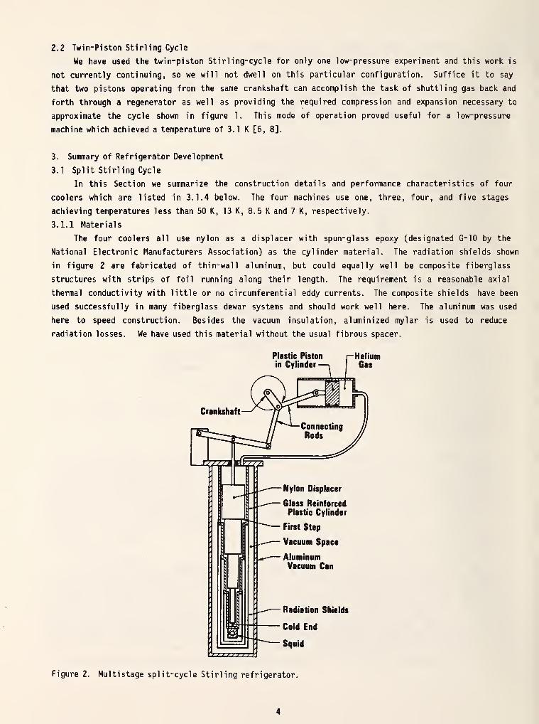
The Stirling-cycle refrigerator described above is readily adapted to multistage operation. A
single stage machine such as shown schematically in figure 1 was found to cool to less than 50 K from
room temperature [1]. Figure 2 shows the simple modification which converts the device to multistage
operation. At each step in the displacer there is an annular space at which cooling takes place. The
successively lower steps (stages) are equivalent to the addition of another refrigerator which rejects
its heat to the step above. Concentric radiation shields from each stage enclose all lower stages so
that radiation is intercepted and pumped at intermediate temperatures where refrigeration efficiency is
high. Further discussion of the split Stirling-cycle refrigerator is contained in references 1 and 10.
2.2 Twin- Piston Stirling Cycle
We have used the twin-piston Stirling-cycle for only one low-pressure experiment and this work is
not currently continuing, so we will not dwell on this particular configuration. Suffice it to say
that two pistons operating from the same crankshaft can accomplish the task of shuttling gas back and
forth through a regenerator as well as providing the required compression and expansion necessary to
approximate the cycle shown in figure 1. This mode of operation proved useful for a low-pressure
machine which achieved a temperature of 3.1 K [6, 8].
3. Summary of Refrigerator Development
3.1 Split Stirling Cycle
In this Section we summarize the construction details and performance characteristics of four
coolers which are listed in 3.1.4 below. The four machines use one, three, four, and five stages
achieving temperatures less than 50 K, 13 K, 8.5 K and 7 K, respectively.
3.1.1 Materials
The four coolers all use nylon as a displacer with spun-glass epoxy (designated G-10 by the
National Electronic Manufacturers Association) as the cylinder material. The radiation shields shown
in figure 2 are fabricated of thin-wall aluminum, but could equally well be composite fiberglass
structures with strips of foil running along their length. The requirement is a reasonable axial
thermal conductivity with little or no circumferential eddy currents. The composite shields have been
used successfully in many fiberglass dewar systems and should work well here. The aluminum was used
here to speed construction. Besides the vacuum insulation, aluminized mylar is used to reduce
radiation losses. We have used this material without the usual fibrous spacer.
Plastic Piston
in CylinderHeliumGas
Radiation Shields
Cold End
Squid
Figure 2. Multistage split-cycle Stirling refrigerator.

3.1.2 Construction
The glass-epoxy (G-10) tubes are purchased from manufacturers stock in a form which is immediately
usable. That is, very little machine work is required on these tubes. The tubes are laid up on very
precise mandrels so the interior finish and dimensions are well controlled. The exteriors of the tubes
are ground and are often not concentric with the inner surface. This is an important fact which must
be considered in the assembly of multistep machines. To construct a machine such as shown in figure 3,
the outer end of each section is machined so that the outside part which slips inside the adjacent
cylinder is concentric with its interior surface. The connections between cylinders and to the
aluminum flange and end cap are all made with epoxy. We have found that it is best to machine these
parts so that they mate with an interference fit. Thus, the epoxy is used primarily as a sealant and
bond rather than a filler. These joints have been highly reliable.
DlsplecerPueh Rod Aluminum
Flange ^ Solid Nylon> Stepped Dleplacer
(In lowest position)
Aluminum Spacer(where required)
Glaee-Epoxy CompositeCylinder Walla
Thin AluminumRadiation Shields
Alumlnlzed Plastic
(10-20 layera In
vacuum apace)
Aluminum End Cap
Cold Space For Device
^Vacuum Wall
Figure 3. Details of a 5-stage, split-cycle Stirling refrigerator.
The drawing is split in two parts to show finer detail.
Dimensions are in millimeters.

The nylon displacer is formed from stock rods which are pinned together to form a multistage
machine. Each rod is individually fitted to its appropriate cylinder prior to assembly of the dis-
placer or the stepped cylinder. In general, the nylon stock is slightly too large and must be machined
to fit the cylinder. These displacer sections are carefully machined to fit the cylinder with almost
no radial clearance, except for a few cm at the large end where about 0.1 mm radial clearance is
provided. During cooldown, differential expansion between the nylon and fiberglass produces a one-
percent radial clearance in the lower portions of the refrigerator. This fitting method is simple and
minimizes the regenerator gap volume, which is important for achieving lowest temperature.
The differential expansion in the axial direction must also be considered. The lengths of the
displacer sections are selected as as to match the lengths of the corresponding sections of the
cylinder when the system is at its lowest operating temperature. This requires some foreknowledge of
the temperatures of the different stages and an estimate of the differential expansion as a function of
temperature. After initial cooldown the displacer is adjusted so that (ideally) all steps reduce their
respective volumes to zero at the bottom of the stroke.
Figure 3 provides dimensional information (in millimeters) on the 5-stage cooler. The upper end
of each radiation shield is slit so that it can be slipped over the appropriate step on the cylinder
and secured with 20 to 40 turns of thin nylon string (unwaxed dental floss is ideal). The bottom ends
of these aluminum tubes are closed with aluminum foil or aluminized mylar which is also secured with
dental floss.
Mylar superinsulation is used between each shield and between the outer shield and the vacuum
wall. We have found that this insulation can be omitted with little effect in the space between the
cold end and the first shield.
All instrumentation wiring (thermometer leads, thermocouple wire and rf leads to SQUIDs) are
thermally anchored at each stage. In one instance, we failed to fully anchor one pair of leads at the
next to bottom stage and found significant deterioration in the bottom end performance. Thermal
anchoring is achieved by securing the leads tightly with dental floss and then coating the area with a
suitable varnish.
3.1.3 Operation
The displacer push rod in figure 3 is fitted with an adjusting screw so that the bottom limit of
the displacer motion can be altered as the system cools down. The range of this adjustment is about
one percent of the displacer length.
After purging the system of air (either simple purging with helium gas or pumping the air out),
the system is filled with helium to between 2 and 4 bars pressure. The piston and displacer are
initially set to 90 phase difference and the system is put into operation. From this point on there
are three adjustments which can be made. These are the phase, the pressure and the displacer spacing
from the cylinder bottom. The latter is the simplest, since the adjustment can be made by noting the
point where the displacer hits bottom and then backing off slightly from that position. The
adjustment of pressure and phase for lowest bottom end temperature is generally different from that for
fastest cooldown and the selection of proper parameters for either optimization is tedious since the
system responds very slowly. It is quite easy to be misled in these adjustments. For example, in
optimizing for lowest temperature one often finds that a small adjustment in phase or pressure results
in a downward trend in temperature, but this trend is only a transient and the final steady state can,
in fact, be higher than the initial temperature. This behavior follows from the fact that these
parameters affect every stage of the refrigerator and the upper stages respond slowly because of their
higher total heat capacities. For the 5-stage machine, we have found that the optimum pressure is
between 2 and 2.5 bars (gauge pressure) and the phase is closer to 45° than 90°.

With the sliding '0' ring seals on the displacer push rod and in the compressor (see Section 3.3),
there is a very gradual buildup of air contamination in the system. This freezes into the lower parts
of the displacer and cylinder and gradually causes friction and sticking of the displacer with a
resultant increase in temperature. The system must be warmed up and purged of these contaminants
before recooling. Presently this problem occurs every one to three weeks depending upon the quality of
the sliding seals. With further engineering work this problem should be eliminated.
A second problem results from the fact that helium diffuses through the spun glass-epoxy
material. Thus, the vacuum space must be continuously pumped to maintain the integrity of the
insulation. The pump can be turned off for only short periods (15 min. to an hour) before the
temperature starts to rise. In principle, this problem could be resolved by laminating a thin metal
foil into the glass-epoxy cylinder to block the diffusion.
3.1.4 Discussion and Summary of Split Stirling Refrigerators
In table I we summarize the characteristics of the four machines which have been built and tested.
The one-stage cooler was really operated with a compressed gas cylinder and valves, that is, in a
Gifford-McMahon cycle, although it could easily have been converted to Stirling cycle. The bottom end
temperature would probably have been about the same. Measurement and modeling of shuttle heat loss [4,
5] indicate that such loss can be reduced by shortening the displacer stroke. This is the reason for
the shorter stroke in the 4 and 5 stage machines.
TABLE 1
CHARACTERISTICS OF FOUR MULTISTAGE CRY0C00LERS
Lowest Temperature
Compressor Di splacement (cc)
Di am. /Length - Stage 1
(both in mm) Stage 2
Stage 3
Stage 4
Stage 5
Stroke (mm)
Temperature - Stage 1
1- Stage
50 K
*
9.6/300
3-Stage 4- Stage
13 K 8.5 K
38 38
19/245 28/150
9.45/143 19/120
4.7/144 9.5/100
4.7/150
12.7 7
120 K 180 K
12.7
50 K
Stage 2 40 K
Stage 3 13 K
Stage 4 8.5 K
Stage 5
*This machine was operated with valves by compressed gas (i.e., Gifford-McMahon cycle).
5- Stage
7 K
90
38/140
29/130
19/120
9.5/83
4.8/133
7
167 K
70 K
27 K
15.5 K
7 K

The addition of more and more stages leads one closer to a continuously tapered displacer, and we
now believe that this might in fact be the next thing to do. The construction will require some custom
fabrication of the displacer and cylinder, but we suspect this may really be simpler than the present
construction which requires a lot of careful fitting and joining of stock tubes and rods. Another
point to make is that a tapered displacer model can really offer a fair approximation to a stepped
displacer machine. In section 4 we consider such a model and find that it describes the stepped
displacer results quite well.
3.2 Twin-Piston Stirling Refrigerator
This development is described rather completely in the paper by Zimmerman and Sullivan [6] with
some additional discussion in reference [8]. Thus we omit extensive description of the device here.
We will emphasize only a few points which are not made in those papers.
The idea behind this machine was to gain lower temperature in a single low- temperature stage. By
reducing the helium pressure to values below atmospheric, one lowers the boiling point of the liquid
and thus maintains nearly ideal gas behavior until this lower temperature is approached. More
importantly, the ratio of regenerator heat capacity to gas heat capacity is enhanced and improves the
regenerative action.
Operating from upper temperatures of 8 to 12 K the machine achieved bottom end temperatures of 3.1
to 4 K as the average pressure was varied from 0.26 to 0.79 bars. In all cases, a small amount of gas
was liquified in the bottom of the cooler, and the temperature achieved was just the boiling point of
helium at the average operating pressure, e.g. 3.1 K at 0.26 bars. To our knowledge, this is the
first Stirling refrigerator in which such liquefaction has been demonstrated.
The twin-piston machine described in reference [6] used epoxy fiberglass for all the lower end
components, so there was no need for concern about differential expansion. The two pistons were set to
a 90 phase difference and no further phase adjustments were made. Such adjustment would have been
difficult because the crankshaft and connecting rods were sealed into a helium-filled enclosure.
This device could be coupled to one of the split Stirling machines to achieve helium temperature
operation in one system, but it must be operated as a completely separate machine because of the low
operating pressure. The complication of combining two refrigerators has caused us to concentrate on
further improvement of the split Stirling-cycle refrigerator in the hope that this machine will prove
suitable for most applications.
3.3 Compressor Design
We report here on the details of construction of three different compressors, a simple '0' ring
sealed piston with conventional crosshead, a balanced force device, and a ceramic oil-free system.
3.3.1 '0' Ring Sealed Piston with Conventional Crosshead
The simplest compressor was constructed with a nylon piston having one or two '0' rings for seals
with a felt pad loaded with silicon grease in an adjacent groove to provide lubrication. A sketch of
such an arrangement is found in reference [1]. This piston was driven at approximately 1 stroke per
second by a motor and crosshead made up of an old commercial freon compressor. The 38 cc compressor
had a piston diameter of 35.6 mm and a stroke of 38 mm. The 90 cc compressor used a stroke of 51 mm
with a piston diameter of 48 mm.

3.3.2 Force Balanced Compressor
There are two problems with the simple compressor. First, the force needed for compression
requires a rather large motor. Much of the work done in compressing the gas can be recovered during
the expansion phase. Thus it is possible to balance this force with other conservative forces so as to
reduce the torque needed to operate the compressor. The first and simplest modification is to keep
helium gas on the back side of the piston at a pressure which is the average value of the system
pressure. This leaves the system at equilibrium with the crankshaft 90 ahead or behind full
compression which reduces the required torque. Further reduction can be accomplished through the use
of a spring and cam as shown in figure 4. An added benefit is that the piston '0' rings are not
directly exposed to the atmosphere. Air leakage is only through the seal around the piston rod.
TO CRANKSHAFT
BALL BEARINGSIN CHANNELS
self-centering^ U-SHAFT COUPLING
ADJUSTED TOLEAK (EQUALIZES
AVERAGE PRESSURE)
TO DISPLACER
Figure 4. Sketch of mechanism used to balance the compressor. The spring and cam are adjusted and
shaped so that the torque at the crankshaft is nearly constant.
3.3.3 Contamination Free Compressor
Ultimately one should address the problem of a design which has no lubricated seals and no
possibility for buildup of air contamination. While the latter has been our more immediate problem, it
is clear that oil-free operation is essential for continuous, long-period use. Over a long period of
time oil vapor would build up deposits in the cold portion of the refrigerator with resultant
deterioration in performance. There are several approaches to the design of a contamination-free
compressor, and while this is not the major thrust of our effort, we describe here some preliminary
experience with one concept.
The compressor shown in figure 5 uses very closely spaced ceramic (alumina) cylinders to effect a
seal during compression. The radial clearance of 4 micrometers allows very little pressure loss during
compression and the back side of the piston is sealed with a metal bellows to complete the gas con-
tainment. The time constant for pressure equalization across the piston is of the order of one minute.
Thus, leakage past the piston is negligible at the operating speed of one stroke per second. This
compressor was operated approximately 60 hours at which point the bellows failed. Subsequently, we
replaced the bellows with an '0' ring seal. This system was run non-stop for over 10 months. The
results of this test indicate some initial wear but little or no wear after about 1000 hours. The wear
is inferred from measurement of leak rate past the cylinder (see figure 6). There is some discrepancy
in the measurements beyond 3000 hours probably due to miniscule accumulation of contaminants on the
surfaces. The measurements at 7100 hours showed a small increase in leak rate when the surfaces were
cleaned with toluene.

Bellows
Ceramic
^) ))))W )wwmnF
Figure 5. Details of design of an oil-free compressor. The clearance between ceramic components is 4
micrometers keeping gas leakage at a negligible level during compression. The compressor was actually
operated vertically.
0.3
aco01
«
AEuo
T
gas—0.34 MPa(gauge)
Ul
1 liter cylinder
Schematic of Leak RateMeasurement
water
CERAMIC COMPRESSOR - Helium Working Fluid
Bore X Stroke - 5 cm X 5 cmSpeed - 1 Hz
Temperature - 2 1 CPressure Excursion - 0.2 to 0.7 MPa (absolute)
1 1 11 62 3 4 5
TIME lOOOHours
Figure 6. Wear measurement for the ceramic compressor. Wear is inferred from change in leak rate with
time. The experimental setup is shown in the insert at top. BDC and TDC stand for bottom dead center
and top dead center, respectively.
3.4 Temperature Control
In abandoning the use of liquid helium in favor of a miniature cryocooler, it is necessary to take
measures to stabilize the temperature of the cold end of the cryocooler. We have observed that small
variations in operating parameters (such as ambient temperature, speed, pressure, impurity buildup,
etc.) cause significant slow variations in cold-end temperature, of the order of 0.1 K or more. Also,
we see a temperature oscillation at the cryocooler frequency (1 Hz). This oscillation is probably
10

quite large in the expansion chamber itself, but may be quite small at the superconducting device,
depending on the thermal resistance between it and the expansion chamber, and on the thermal mass of
the device and associated hardware. In the four-stage cryocooler, the amplitude of the oscillation was
about 2 mK at 8.5 K, as measured by a carbon resistance thermometer cemented into a brass block screwed
to the bottom of a helium gas thermometer bulb clamped to the cold end of the cryocooler (see figure
7). The amplitude measured by the gas thermometer was about 5 mK. It is to be expected that the
amplitude of temperature oscillation should be larger, the closer the thermometer is to the expansion
space. It will also, of course, be a function of the response time of the thermometer.
In order to stabilize and control the temperature of the brass block (which simulates a SQUID with
mounting hardware) shown in figure 7, we assembled the simple circuit shown in figure 8 to amplify the
dc-signal from the carbon resistance thermometer and feed it back to the 10,000-ohm resistance heater.
Thus if the control resistance R in the bridge is set lower than the thermometer resistance R-r with
feedback loop open, the closed-loop output of the amplifier will provide power to the heater R,, to
raise the temperature of the brass block until the bridge is balanced. Initial tests of this control
system showed that slow changes in temperature become imperceptible (no more than a fraction of a mK in
a two-hour period). Because of the rather slow thermal response, the simple circuit did not
significantly reduce the 2 mK oscillation at 1 Hz. We intend to work on electronic regulation of the
oscillatory component in the future.
Another method for stabilizing the temperature is to increase the heat capacity of the object
attached to the cold end. This might best be done with helium gas in a small volume between the cold
end and the SQUID. The situation would be like that of figure 7. We found that the heat capacity of
this system could easily be increased by a factor of 10 or more by filling the 1 cc volume to only 4 or
5 bars of pressure. This results in a 10-fold reduction in the oscillatory component of temperature
variation. This also reduces the drift rate significantly.
This latter method of temperature stabilization can readily be developed further. The concept is
analagous to electronic filtering with resistor-capacitor combinations. The heat capacity of an object
is the analog of electrical capacitance and thermal resistance is the analog of electrical resistance.
Using this analog, one realizes that thermal resistance should be introduced between the refrigerator
and gas reservoir to improve the filtering.
4. Cryocooler Optimization
4. 1 General Approach
The general design philosophy for these cryocoolers involves one fairly simple assumption; to
minimize refrigerator interference one should operate with the smallest possible drive power. In other
words, the larger the drive machinery, the greater will be the magnetic and vibrational
interference for any SQUID or other system supported by the refrigerator. Thus, when we say optimum
design, we mean minimization of the power requirement for the system.
We have selected a tapered displacer Stirling cooler for this calculation with the following
thoughts in mind. First, we can cover the entire temperature range from just above liquid helium
temperature to room temperature with a single calculation. Second, the results will provide design
guidance, even for stepped displacer machines. That is, the result of the calculation is an optimum
shape and size for the displacer and this can be used to estimate the lengths and diameters of the
stages in an optimum stepped displacer machine. Finally, we would like to consider the construction of
a tapered displacer system in the future.
The idea in this calculation is to express the refrigeration and losses as time-averaged functions
of the parameters of the system (heat capacity, thermal conductivity, position along the displacer,
11

stroke, frequency, etc.). The losses are balanced against the refrigeration with the functional form
of the taper (cylindrical symmetry) finally determined by using a variational method to minimize ^he
power required to run the system.
NYLON DISPLACER
EPOXY-GLASS CYLINDER
EXPANSION SPACE
ALUMINUM END PLUG
GAS THERMOMETERBULB (BRASS)
HEATER (10 kO)
CARBON RESISTANCETHERMOMETER
(220 NOMINAL)
BRASS BLOCK
Figure 7. Bottom-end details of the 4-stage cooler with electronic temperature control
the bulb adds significant thermal mass and thus adds to temperature stability.
Helium gas in
BRASS BLOCK
5M
DIFFERENTIALAMPLIFIER
-±r COMPENSATEDINTEGRATOR
Figure 8. Simple temperature control bridge circuit. The amplifier delivers current to the heater so
as to match RT to R .
c
12

4.2 The Calculation
In this calculation we consider three loss terms; conduction, radiation, and shuttle heat loss.
These are the dominant losses for the temperature range of about 15 to 300 K. Below 15 K one should
include the enthalpy deficit and regenerator inefficiency. These terms are more complex because they
include the mass flow of the working fluid. Thus, as a first step we consider the limited problem
which nonetheless results in useful design information in the temperature range above 15 K. Despite
the potential for some error below 15 K, we have extended the calculations to 10 K.
The net heat leak can be expressed as
^ ~ ^cond ^rad ^shuttle
= 7tr2k(dT/dx) + 2eoT
3Af(x) (dT/dx) + S
2r(nnkC/2)
1/2(dT/dx)
, (1)
where k is thermal conductivity and C is specific heat, both of which are functions of x. r is the
radius, S is the stroke, A is the surface area of the radiation shields, n is the operating frequency,
and e and a are constants relating to radiation. f(x) is a function which describes the distribution
of insulation along the refrigerator, x is the position along the displacer and the radius r is taken
as a general function of x, so that the taper profile is as yet unspecified. The third term, shuttle
heat loss is taken from reference [4].
The thermal conductivity and specific heat of the displacer and cylinder are functions of
temperature and must be explicitly included in the calculation. From a combination of sources
including reference [4], we have generated the following power series representations of thermal
conductivity, k(T), and specific heat, C(T) for the G-10 material in the range from 5 K to 300 K.
k(T) = 9.17 x 10" 2+ 3.19 x 10" 3
T - 3.67 x 10_6
T2
, (2)
C(T) = - 1.49 x 10⁴
+ 3.75 x 10³T + 3.35 x 10
]
T2
- 9.21 x 10_2
T3
, (3)
•3
where k(T) is in units of W/K-m and C(T) is in J/K-m .
The diameter at the bottom end of the displacer is set by equating the refrigeration at the bottom
end with the heat leak into the same point, that is,
2
Q(ro) = 7rr
oSn P,/n(P
u/P
£ ) (4)
13
where r is the bottom end radius and P and P. refer respectively to the upper and lower pressures.
The expression on the left is the sum of the heat losses (eq. 1) evaluated at r = rQ
(or equivalently,
at x = 0). The refrigeration term is an ideal one; it should be reduced by about one half for the
real sinusoidal drive.
The ideal work required by the refrigerator is given by
W=/((Tamb
/T - 1) (dQ/dx) dx, (5)
where the integral is over the length of the machine. The first term inside the integral is the Carnot
coefficient and T , is the ambient (room) temperature.
Equation 4 can be solved for r as a function of T (the bottom temperature) and (dT/dx) ~. Thus
if we select an arbitrary function, T(x), to describe the temperature profile, we can calculate a value
for r and then, having differentiated Q with respect to x, we can calculate the net work (eq 5) for
this temperature profile. Equation 4 can also be used to find r as a function of x; since the heat
flow at a point, x, is intercepted by the refrigeration below that point to the displacer length.
The results described are for a specific T(x) and thus do not represent any sort of optimum, but
we do have all of the ingredients for a variational determination of the optimum T(x) and thus dis-
placer shape. We select a power series for T(x),
T(x) = TQ
+ T1
X + T2
X2
+ T3
X3
+ . . . . , (6)
where the sum of the coefficients, T , is equal to Tb-T
h. . if x is normalized to the displacer
length. An arbitrary set of coefficients (usually only a linear term) is chosen and after calculating
the work, the coefficients are varied to find if this increases or decreases the work and only changes
which decrease the net work are accepted. By successive iterations of this process for all of the coe-
fficients we converge upon the best possible temperature profile and displacer shape. The absolute
length of the displacer is an input parameter.
4.3 Results
Figure 9 shows the results of this computer generated solution for a 50 centimeter long displacer
which is comparable to that used in our 4 and 5 stage machines. The stroke is 5 mm, the cylinder wall
thickness is 3 mm, and the frequency is 1 Hz. The 4 radiation shields are taken to have an average
diameter of 10 cm and 40 layers of aluminized mylar are distributed between these shields. The upper
and lower pressures are 6 and 3 bars, respectively. These parameters are consistent with the values
for the 4 and 5 stage coolers described in section 3. The net work (ideal) required in this
refrigerator calculation (10 K bottom end temperature is 0.564 watt with 0.211 watt going to conduction
loss, 0.214 watt to shuttle heat loss, 0.082 watt to radiation loss, and 0.057 watt required to cool
the bottom end. The bottom end term is primarily shuttle and conduction heat flow which is
proportional to the temperature gradient and the cross-sectional area at the bottom end. It would be
zero if the wall thickness and displacer radius could be tapered to zero, but this is obviously
impractical. Our choice of a constant 3 mm wall thickness over the whole length was arbitrary, but the
14
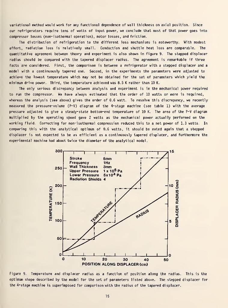
variational method would work for any functional dependence of wall thickness on axial position. Since
our refrigerators require tens of watts of input power, we conclude that most of that power goes into
compressor losses (non-isothermal operation), motor losses, and friction.
The distribution of refrigeration to the different loss mechanisms is noteworthy. With modest
effort, radiation loss is relatively small. Conduction and shuttle heat loss are comparable. The
quantitative agreement between theory and experiment is also shown in figure 9. The stepped displacer
radius should be compared with the tapered displacer radius. The agreement is remarkable if three
facts are considered. First, the comparison is between a refrigerator with a stepped displacer and a
model with a continuously tapered one. Second, in the experiments the parameters were adjusted to
achieve the lowest temperature which may not be obtained for the set of parameters which yield the
minimum drive power. Third, the temperature achieved was 8.5 K rather than 10 K.
The only serious discrepancy between analysis and experiment is in the mechanical power required
to run the compressor. We have always estimated that the order of 10 watts or more is required,
whereas the analysis (see above) gives the order of 0.6 watt. To resolve this discrepancy, we recently
measured the pressure-volume (P-V) diagram of the 4-stage machine (see table 1) with the average
pressure adjusted to give a steady-state bottom-end temperature of 10 K. The area of the P-V diagram
multiplied by the operating speed gave 2 watts as the mechanical power actually performed on the
working fluid. Correcting for non- isothermal compression reduced this to a net power of 1.3 watts. In
comparing this with the analytical optimum of 0.6 watts, it should be noted again that a stepped
displacer is not expected to be as efficient as a continuously tapered displacer, and furthermore the
experimental machine had about twice the diameter of the analytical model.
300
~ 200
Ul
~~l I
1
—
StrokeFrequencyWall ThicknessUpper PressureLower PressureRadiation Shields
5mm1Hz3mm1 x 105 Pa5x104 Pa4
10 20 30 40POSITION ALONG DISPLACER (cm)
50
Figure 9. Temperature and displacer radius as a function of position along the radius. This is the
optimum shape described by the model for the set of parameters listed above. The stepped displacer for
the 4-stage machine is superimposed for comparison with the radius of the tapered displacer.
15

With this calculation as a reference, we successively varied the stroke, the length, and the
frequency to see whether better values could be predicted. The results are shown in figure 10. While
the length of a half meter was selected somewhat arbitrarily, the stroke and frequency were varied
experimentally to arrive at the values given by the circles in figure 10. It is interesting to note
how closely the calculation predicts the best set of values for these parameters. The optimum stroke
of * 3.5 mm is close to the value of 5 mm used in the refrigerators, and while the minimum power occurs
for a displacer length of one meter, the half meter value which is more practical does not produce too
dramatic a rise in system power. As for the frequency, it is clear that one should operate at the
lower end of the flat portion since the inclusion of regenerator efficiency will probably cause the
right end of the curve to be lifted. The gradual rise in power requirement with displacer length
reflects the increase in radiation loss which is itself quite small.
I I I I
g1.0 - y^ -
ocUJ
2 0.6 - N. y^
0.2 i i i i
ocLU
oo.
4 6
STROKE (mm)
0.4 0.8 1.2 1.6
DISPLACER LENGTH (m)
1.6 2.4
FREQUENCY (Hz)
4.0
Figure 10. Power requirement as a function of stroke, speed, and displacer length. Each of the 3
parameters is varied separately with the remaining parameters held at the values given in figure 9.
16

One can also account for excess dissipation by some apparatus at the bottom of the refrigerator.
For the reference conditions (parameters) described above we note a linear increase of require drive
power, 35.7 mW, for each mW of refrigeration at 10 K for power dissipations of up to 20 mW. There is,
of course, a commensurate increase in the diameter of the bottom end of the displacer.
5. Summary and Conclusions
It now appears that this new class of low-power Stirling cryocoolers can be compatible with
superconducting sensors, at least for modest sensitivity. Several engineering problems remain to be
solved. First, the compressor needs to be designed for dry operation to eliminate any contact between
the helium gas and oil. This will require some effort, although the low speed and low working pressure
offer possibilities for simple solutions. The problem of helium diffusion through the displacer
cylinder should be eliminated with some sort of diffusion barrier. Finally, considerably more work
should be done to isolate and identify magnetic interference mechanisms. This could permit extension
of the devices to more demanding applications.
All things considered, we feel that the analytical results agree remarkably well with the
experimental measurements, insofar as valid comparisons can be made. Thus, the tapered displacer model
seems to provide reasonable guidance for refrigerator design. It would be especially useful to extend
the calculations to include regenerator inefficiency and enthalpy deficit. The present calculations
suggest that a linear taper (cone) will suffice for temperatures down to 10 K, but we suspect that the
extra losses below this temperature will require a more complex taper. In any case, it should prove
useful to build a continuously tapered system, since success with this concept could lead to improved
performance and simplified construction.
6. References
[I] Zimmerman, J. E. , Radebaugh, R. , and Siegwarth, J. D. , in "Superconducting Quantum InterferencesDevices and their Applications," (H. D. Hahlbohm and H. Lubbig, eds.), Berlin, Walter de Gruyter(1977), pps. 287-296.
[2] Zimmerman, J. E. , Radebaugh, R. , and Siegwarth, J. D. , "Refrigeration for Small SuperconductingDevices," Conf. German Refrigeration Society, Munich (October 1976).
[3] Zimmerman, J. E. and Radebaugh, R. , in "Applications of Closed-Cycle Cryocoolers to Small Super-conducting Devices," NBS Special Publication SP-508, J. E. Zimmerman and T. M. Flyn, eds.), Super-intendent of Documents, U. S. Government Printing Office, Washington, D. C. 20234 (1978). (Alsoavailable from the authors), pp. 59-65.
[4] See ref. 3 pps. 67-73.
[5] Radebaugh, R. in "XVth International Congress of Refrigeration," Venice, Italy, Sept. 1979 (In
press).
[6] Zimmerman, J. E. and Sullivan, D. B. , Cyogenics ]9, pp. 170-171, (1979).
[7] Zimmerman, J. E. in "Future Trends in Superconductive Electronics," (B. S. Deaver, Jr., C. M.
Falco, J. Harris, and S. W. Wolf, eds.) AIP Conf- Proceedings Number 44, New York, American Instituteof Physics, 1978, pps. 412-420.
[8] Sullivan, D. B. and Zimmerman, J. E. , Int. J. of Refrig. 2, pps. 211-213, (1979).
[9] Zimmerman, J. E. in "Proceedings of the SQUID Geophysics Workshop," Los Alamos, NM, June 1980. (In
press).
[10] Zimmerman, J. E. in "SQUID 80: Superconducting Quantum Interference Devices and their Ap-
plications" (H. D. Hahlbohm and H. Lubbig, eds.) Berlin, Walter de Gruyter (1980), pps. 424-443.
[II] Sullivan, D. B. , Zimmerman, J. E. , and Ives, J. T. in "Refrigeration for Cryogenic Sensors andElectronic Systems," NBS Special Publication SP-607, (J. E. Zimmerman, D. B. Sullivan, and S. E.
McCarthy, eds.), Superintendent of Documents, U. S Government Printing Office, Washington, D. C. 20234(1981). (Also available from the authors), pps. 186-194.
17

[12] Zimmerman, J. E. , Sullivan, D. B. , Kautz, R. L. , and Hobbs, R. D. , See ref. 11, pps. 173-177.
[13] Cox, J. E. and Wolf, S. A., see ref. 3, pps. 123-129.
[14] Nisenoff, M. , see ref. 11, pps. 195-209.
18

7. Appendix - Publications generated by the Cryocooler Program. The original page numbers have been
deleted so as to provide continuous numbering in this volume. Original page numbers are included in
the reference at the beginning top of each publication.Page
1. Possible Cryocooler for SQUID Magnetometers 20
2. Refrigeration for Small Superconducting Devices 30
3. Operation of a SQUID in a Very Low-Power Cryocooler 38
4. Shuttle Heat Transfer in Plastic Displacers at Low Speeds 45
5. Analysis of Regenerator Inefficiency for Stirling-Cycle Refrigerators withPlastic Displacers 52
6. A Milliwatt Stirling Cryocooler for Temperature below 4 K 58
7. Cryocoolers for Superconductive Electronics 60
8. Very Low-Power Stirling Cryocoolers Using Plastic and Composite Materials 69
9. Cryocoolers for Geophysical SQUID Magnetometers 72
10. Cryogenics for SQUIDs 75
11. Operation of a Practical SQUID Gradiometer in a Low-Power Stirling Cryocooler 96
12. Measurement of Thermal Properties of Cryocooler Materials 105
19

"Superconducting Quantum Interference Devices and their Applications," (H. D. Hahlbohm and H.
Liibbig, eds.) Berlin, Walter de Gruyter (1977), pps. 287-296.
POSSIBLE CRYOCOOLERS FOR SQUID MAGNETOMETERS*
J. E. Zimmerman, R. Radebaugh and J. D. SiegwarthCryogenics Division, National Bureau of Standards,Boulder, Colorado 80302 USA.
ABSTRACT
In a study to determine if a cyclic cryogenic refrigerator issuitable for cooling SQUID magnetometers and similar instru-ments, we have used a specially designed Stirling machine witha three-stage displacer to achieve and maintain a temperatureof 13 K. The displacer and cylinder were made of low-suscepti-bility, nonconducting plastic to minimize magnetic interference.For the same reason, and also to minimize mechanical noise,the machine operates at low displacement and low speed, and ituses only about 10 W of mechanical power, requiring 50 W inputto a typical small electric motor. Since the temperatureachieved is within the range of NbN and Nb^Sn SQUIDs, it can,
in principle, be used to cool a SQUID. The estimated magneticsignal from the reciprocating displacer may not seriouslyaffect the magnetometer sensitivity, but the signal due to thecyclic pressure-induced geometric distortion of the SQUIDmounting in the earth's field may be very difficult to eliminate,
INTRODUCTION
In this paper we address a subject that is always implicit,but not usually expressed in detail, in any application ofsuperconductivity, namely, the cryostat. For small devices,such as SQUIDs, the universal practice is to use liquid-helium cryostats with a variety of shapes, sizes, and specialfeatures. (1) It need hardly be pointed out that the cost andinconvenience of procuring and handling liquid helium, theattendant restrictions on how the instrument can be mountedand handled, and the inherent intermittent nature of theoperation, all contribute to the obvious disadvantage ofsuperconducting devices relative to competing devices operatingat or near ambient temperature.
The alternative to liquid-helium cooling is to use a closed-cycle cryogenic refrigerator (hereafter referred to as acryocooler) . The use of a cryocooler replaces the disadvan-tageous features noted above with a whole set of new ones.Limited reliability is perhaps the most often mentioned;others are maintenance requirements, cost, and, as we shallsee, magnetic and mechanical interference due to moving parts.With regard to reliability, there seem to be two schools ofthought, corresponding roughly with the high reliability ex-pounded by cryocooler manufacturers on the one hand, and the
Contribution of NBS, not subject to copyright.
20

low reliability expected by potential users on the other. (2)
The fact is that very few cryocoolers are in use today tooperate small superconducting devices, so there is no sub-stantial body of experience regarding reliability or anythingelse.
There are several intermediate solutions to the cryogeniccooling problem. One of these is a liquid-helium cryostatincorporating one or more radiation shields maintained atrather low temperatures by an auxiliary cryocooler, which maygreatly reduce the helium evaporation rate. (3) Such a systemcombines some of the best, and some of the worst, features ofboth worlds. One of the good features is that it permits oneto get practical experience in the use of cryocoolers withoutbeing fully committed, in the sense that if the cryocoolerturns out to be no good one still has a cryostat. Anotheruseful feature is that the cryocooler can be turned off forperiods of several hours of critical measurements, where themagnetic and mechanical noise of the cryocooler might beintolerable, with only a slight increase in liquid-heliumconsumption.
There are some other types of cryostats which may be usefulfor particular applications. For example, a cascaded Joule-Thomson system operating from cylinders of compressed gasesmay be suitable for intermittent short-term operation withquick cooldown. -It is beyond the scope of this paper todiscuss all possible cryostatic systems, even by way of in-troduction, and we will hereafter restrict the discussion tothe use of liquid-helium and closed-cycle refrigerators(cryocoolers) using helium gas as the working fluid.
In fact, there is only one known type of practical, small,self-contained system which can maintain superconductingtemperatures in a 300 K environment. This is the type usinghelium gas as a working fluid in a cycle involving isothermalcompression at room temperature and isothermal expansion, or acombination of isothermal expansion and other processes, atone or more low temperatures. The particular point to beemphasized here is that compression and expansion requiremoving parts, which may be very difficult to operate in a waythat will not interfere with the operation of highly sensitivemagnetometers
.
We have chosen the Stirling machine as an analytical andexperimental model to investigate the problems associated withoperating SQUID magnetometers with a small closed-cycle helium-gas cryocooler. It is a very simple machine, shown schemati-cally in Figure 1, which has only two essential moving parts,a piston and a displacer. (4) The displacer fits loosely inits cylinder so that gas can move freely past it. Thus thepressure P is nearly the same throughout the total volume V of
21

PISTON
T 2
REGENERATORGAP
Q, Rejected
Absorbed
REGENERATORHEAT CAPACITY
(Qa= Qb for
Perfect Gas)
Figure 1 Schematic representation of operation of splitStirling machine and idealized thermodynamic cycleon temperature-entropy diagram.
the system. Work W = /PdV may be done on the system as thepiston moves back and forth, but no work is done by or on thedisplacer since displacer motion does not change the volume.Referring to Fig. 1, when the displacer is in its lowestposition, the piston is moved to the left, compressing theworking fluid and producing a heat of compression Qi which isrejected at ambient temperature T^, typically 300 K. Next,the displacer is moved to the top of its cy liner, so theworking fluid moves (is "displaced") from the top to thebottom of the cylinder. If we may assume that the machine isalready in steady-state operation, with the bottom end at alow temperature T2, and a stable temperature gradient alreadyestablished along the displacer, then the fluid being dis-placed gives up heat Q to the displacer and cylinder wallsalong the annular gap, and arrives at the bottom end at tem-perature T2. Then the piston is moved to the right, expandingthe fluid and producing a flow of heat Q2 into the fluid attemperature T
2at the bottom of the cylinder. Finally, the
displacer is moved to its lowest posj-tion, displacing theremainder of the fluid back to the top of the cylinder andcompleting the cycle. The fluid picks up heat Qb from thewalls of the annular gap as it travels up from T2 to T,
.
In steady state operation it is required that Q = Q^,otherwise the temperature gradient along the displacer and
22

cylinder will change with time. With real gases, such ashelium at 20 K and below, the requirement Qa = Q^ is incom-patible with the assumption of isothermal heat exchange Qi andQ2 at T^ and T 2 . (i.e., The enthalpy change Qa or Q^ betweentwo given temperatures T^ and T 2 depends on pressure, so therequirement Qa = Qu means that the expansion cannot be strict-ly isothermal. This is a limitation, or at least an analyti-cal complication, in the operation of the Stirling cycle.
A more serious limitation, which we will have more to sayabout, is that the heat capacity of the walls at the cold endbecomes insufficient, relative to that of the fluid, toefficiently provide the necessary heat exchange Q and Q, .
Considerable research has been devoted to finding materialswith favorable properties (large heat capacity and thermalconductivity) to use in regenerative heat exchangers at lowtemperatures. For use with SQUID magnetometers we would liketo impose additional restrictions on the material, namely,that it also have favorable properties relative to generationof electromagnetic interference and noise in the SQUID.
EXPERIMENTS WITH PLASTIC DISPLACER-REGENERATORS
Our experiments are intended only to demonstrate feasibilityof specific materials in a specific refrigerating mechanismwhich may have a possibility of satisfying the stringentrequirements of a SQUID magnetometer.
The first experiment was to build a singlestage displacer-regenerator (Fig. 2) of the type invented by Stirling in 1816,but using modern materials. The displacer was a nylon rod 9.6mm diameter by 300 mm long. It operated inside a spun-glassepoxy cylinder (designated G-10 by the National ElectronicManufacturers Association) with 2.4 mm wall thickness. Theradial clearance between displacer and cylinder was about .07.07 mm, and the length of the cylinder was 313 mm, allowinga 12.7 mm stroke for the displacer, which was connected to athin brass push rod running through a sliding rubber seal atone end of the cylinder. The push rod was operated by ascotch yoke at the end of a shaft which was turned at 1 Hz bya small electric motor. A pair of cams, 90° out of phase, onthe same shaft, operated the inlet and exhaust valves. (5) Theworking fluid was helium gas, supplied at 14 atmospheres froma storage cylinder and exhausted to the atmosphere when ex-panded. Twenty-five layers of aluminized plastic sheet werewrapped around the displacer cylinder, which was mounted in anevacuated metal cylinder. Operated at 1 Hz, the machineattained a temperature in the neighborhood of 50 K three orfour hours after starting, and maintained the temperature forabout two days on a cylinder of helium.
23

Helium gas
from regulator /
Common shaft to cams and scotch yoker
/ n t
^&ntake valve
Camoperated'
Exhaust valve
Solid nylon displacer
'6-10" Epoxy glass cylinder
Aluminized plastic
radiation shields
Press fit and cement
Vacuum wall —
Pushrod to
scotch yoke
Rubber seals
t Narrow radial
gap regenerator
Figure 2 Details of simple cryocooler operating from com-pressed helium gas cylinder. Radial gap arounddisplacer is too narrow (^0.05 mm) to be shown inthis drawing. Displacer was 9.5 mm diameter by300 mm long, with 12.7 mm stroke.
The success of this simple apparatus in producing rather lowtemperatures encouraged us to construct a 3-stage, closed-cycle, split Stirling machine, (6) using the same materials andtechniques (Fig. 3). Dimensions of the stages were as fol-lows: The first stage displacer-regenerator was 245 mm longand 19 mm diameter, with 0.05 mm radial clearance inside thespun-glass epoxy cylinder. The second stage was 143 mm longand 9.45 mm diameter with 0.07 mm radial clearance. The thirdstage was 144 mm long and 4.7 mm diameter with 0.04 mm radialclearance. The cylinders all had a 2.4 mm wall thickness andwere epoxied together using a commonly available epoxy glue.A brass cap was epoxied on the bottom or cold end. Cylindri-cal aluminum radiation shields were fitted over the lower endof the first and second stages. Several layers of aluminizedplastic sheet were wrapped within the shields and around theoutside of the assembly for additional radiation shielding.A polished stainless steel cylinder containing a 35.6 mmdiameter plastic piston formed the compressor. The variousdimensions of these machines were dictated by intuition andby immediate availability of materials. In subsequent workwe hope to optimize the size and shape on a more rationalbasis. The piston was driven through a 38 mm stroke by a
24

1 m Connecting line
Pushrod to
scotch yoke
Rubber
piston ring
Felt
grease ring Press fit
and cement
Piston rod to
crosshead
and crankshaft
Radiation shields
Vacuum wall —
Figure 3 Three-stage Stirling cryocooler. Displacer sectionswere 19 nun, 9.5 mm, and 4.7 mm diameter, and 245 mm,143 mm, and 144 mm long, with 12.7 mm stroke. Pistonwas 35.6 mm diameter with 38 mm stroke.
crankshaft and crosshead mechanism adapted from a small commer-cial freon compressor. Operating at 1 Hz with a displacerstroke of 12.7 mm and a pressure excursion of about 3 to 13 Pa,this machine maintained a temperature below 16 K.
This machine was also operatedfor the first cryocooler, andtemperature of 16 K. The perfthe dead space around the dispdisplacer had a larger coefficglass epoxy cylinder, so that"dead space" at the cold end a
achieved. We therefore carefucontraction and machined the dthe displacer and cylinder fitstate operation, rather than a
with the same valved cycle usedreached almost the same minimumormance was improved by reducinglacer. We found that the nylonient of expansion than the spun-there were several millimeters offter steady-state operation waslly measured the differentialisplacer accordingly, so thatted together precisely in steady-t room temperature. After
25

initial cooldown, the dead space was eliminated by readjustingthe length of the push rod. When this was done, and the phaseangle between piston and displacer was empirically optimized,the cryocooler maintained a temperature around 13 K or less,for continuous periods as long as 5 weeks. The limit on non-stop operation appeared to be due to air being entrapped bygrease on the piston ring and the pushrod seal and contami-nating the helium gas. Such contamination would eventuallybuild up, reduce the radial clearance of the displacer, andcause friction. We eliminated most of the contamination bymaintaining an ambient helium atmosphere on the back side ofthe piston, but have not yet done so for the pushrod seal.
This three-stage displacer has been operated a total of nearly5000 hours with no obvious signs of wear. It will maintain atemperature between 12-1/2 and 13 K at the cold end with noheat load. With a heat load of 11 mW the temperature rises to14.5 K. The outer radiation shield is maintained at 120 K andthe inner radiation shield at 40 K. Operated at f = 1Hz witha pressure excursion as noted above, the mechanical power re-quired for the compression stroke, assuming an isothermalprocess, is PjV.f (lnP
2/P
1) = (3 x 10 5
) (38 x 10" 6) In (13/3)
watts = 15 W, where V. = 38 cm is the piston displacement.
Since a considerable fraction of the work is returned on theexpansion stroke, the net power required was estimated to beof the order 10 W or less. This estimate was confirmed byoperating a similar machine with a 50 watt motor whose effi-ciency was less than 25%.
We have recently made fairly extensive measurements andcalculations of the various components of intrinsic heat loadin this machine, namely, shuttle heat, conduction, radiation,and regenerator inefficiency, for the purpose of optimizingthe design. In this connection, we may wish to complicate thedesign slightly by incorporating a high-heat-capacity matrixat the cold end of the displacer cylinder, to improve theregenerative heat exchange and achieve lower temperature. Theresults of our measurements and the optimization will besubmitted for publication subsequently.
CONSIDERATION OF COMPATIBILITY WITH A SQUID MAGNETOMETER
Having demonstrated that superconducting temperatures (high-Tc ) can be achieved and maintained for long times with a verylow-power cryocooler made of plastics with favorable magneticproperties, it remains to be seen whether such a machine canbe used with a highly sensitive SQUID magnetometer. Ignoringfor the present the problem of the compressor and its drivemechanism, consider the magnetic signals generated by justthose parts that would be near the SQUID, namely the bottomend of the displacer and its cylinder. In our experimental
26

machine, the end of the displacer is 4.7 mm diameter and movesup and down about 13 mm. In the field of the earth, 0.5 x10""4 t, this gives a peak-to-peak magnetic moment at 1 Hz of
about 0.3 cm 3x 0.5 x 10~ 4
T x 1.1 x 10~ 5= 0.16 x 10~ 9
T cm3.
The susceptibility of nylon, 1.1 x 10"^, was measured for usby F. Fickett.
If a SQUID were mounted 5 cm (for example) from the end ofthe displacer, the peak-to-peak field at 1 Hz would be about
-1210 ' ' T. A coherent oscillation of this magnitude could besubtracted from the output with an accuracy of perhaps 10"^-^ T,which is comparable to present SQUID sensitivities in a 1 Hzbandwidth. Thus, one may be able to cope with the magneticsignal from a small reciprocating displacer of nylon or com-parable material.
On the other hand, a peak-to-peak pressure excursion of 10 Pa5 ^
(10 Pa = 1 atmosphere) in the displacer cylinder will causeit to bend owing to non-uniform wall thickness and otherdefects. If the SQUID were mounted on the end of the cylinderfor mechanical support, bending of the cylinder in the earth'sfield may cause a flux change in the SQUID far too large to besubtracted from the output with sufficient accuracy. There isno need to use precise numbers to show this. An elastic
modulus of 10 Pa and a pressure change of 10 Pa in a cy-linder whose ratio of length to diameter is 10 gives a bend of
the order of 10 x 106x 10
-11x 10~ 2
= 10~ 6 radians, if thelateral inhomogeniety (different wall thickness, for example)is of order 10~2. in the earth field this would appear as anoscillation of the order of 10~10 t. Two alternative approachessuggest themselves for reducing this signal. One is to mea-sure the bending and empirically correct it by grinding orscraping one side of the cylinder. The other is to mount theSQUID on an independent support with only a flexible thermalconnection to the cold end of the cylinder. In any case, itmay be quite difficult to reduce or compensate the bendingsignal to a level of 10~ 14 T.
COMPARISON OF THE CRYOCOOLER WITH CONVENTIONAL LIQUID-HELIUMCRYOSTATS
We have shown that the lowpower cryocooler can maintain tem-peratures below 15 K with ten or twenty milliwatts heat load.Bias power requirements for SQUIDs are many orders of magni-tude smaller than this, and the only significant heat loadimposed by the SQUID is conduction down the electrical leads.Our experience with conventional liquid-helium cryostatsindicates that, with good design, the conduction heat load canbe reduced to less than ten milliwatts. Actually, designingor specifying cryostats on the basis of refrigeration capacityat the coldest point is quite misleading. What is important
27

is to distribute the refrigeration capacity, using a multi-stage machine, so that the bulk of the heat input (conduction,radiation, etc.) is pumped at relatively high temperatures,leaving very little to be pumped at the lowest temperature.The distribution of refrigeration capacity vs temperature isanother aspect of design optimization which has receivedlittle attention in the literature. For comparison, a typicalsmall liquid-helium cryostat with an evaporation rate of oneliquid liter per day (corresponding to about 700 liters of gasat room temperature) is supporting a total heat load, intrin-sic plus imposed, of 29 mW at 4.2 K, and has the capability ofabsorbing an additional 7.6 m W/K due to the heat capacity ofthe vapor, which is approxmately independent of temperature.These figures might be used as a guide for the necessaryrefrigeration capacity of a small cryocooler. Actually, thefigures should be quite conservative because (1) a cryocoolerwould not have the large cold reservoir and (2) optimum designwould probably not require the temperatureindependent heatabsorption capacity, but rather would concentrate the refrig-eration capacity at higher temperatures.
FURTHER PERTINENT COMMENTS
The work we have reported here is unique in two respects,first in the choice of materials and construction methods forthe displacer, and second in building a machine with at leastan order of magnitude lower input power requirements thanprevious comparable machines. Both of these features are, ofcourse, related to our particular aim of minimizing magneticinterference, but they will have considerable effect on costand portability as well. It appears from our experiments thatthe cost of a cryocooler could easily become comparable to thecost of a SQUID magnetometer or similar superconducting in-strument. Such systems might well be justified economically,in view of the fact that the cost of liquid helium will in-crease as the supply diminishes, whereas the cost of cryo-coolers should decrease substantially if they are produced insufficient numbers to replace present liquid-helium cryostats.
This work completes what might be called a preliminary studyof the feasibility of using a small mechanical cryocooler forSQUID magnetometers and other small superconducting devices.We conclude that a second phase of development is justified.We believe this should include (1) optimizing the design asnoted above, (2) incorporating a high-Tc SQUID with which tomeasure and evaluate the level of magnetic interference fromthe various moving parts, and (3) evaluating other potentiallyuseful materials and refrigeration processes which may improvethe performance.
28

ACKNOWLEDGEMENT
We are grateful to several individuals for helpful commentsand criticism, particularly Sam Collins, Dave Daney, T. R.
Strobridge, and R. 0. Voth. This work is supported jointly bythe National Bureau of Standards, the Office of Naval Resarchand the Naval Electronics Systems Command.
REFERENCES
1. For example, we have built 1.7-liter spun-glass-epoxycryostats with hold times of nearly three days on onefilling of liquid helium. At the opposite extreme, a180-liter cryostat has been built with a hold time of102 days. See R. J. Dinger, J. R. Davis and M. Nisenoff,NRL Memorandum Report 3256, Naval Research Laboratory,Washington, DC (March, 1976).
2. Some contrasting comments on reliability by differentpeople (not directed specifically at each other) maybe found in Proc. Cryogenic Cooler Conf., AFFDL-TR-73-149, Air Force Flight Dynamics Laboratory,Wright-Patterson Air Force Base, Ohio 45433 (Dec.1973). This report also contains several papers onrecent developments in miniature cryocoolers forthe 10-20 K range.
3. R. C. Longsworth, p. 390, Proc. Fifth International Cryo-genic Engineering Conf. , IPC Science and TechnologyPress (1974), has shown that liquid-helium hold timescan be increased by a factor of 4 or more by main-taining a shield at 20 K rather than at 77 K. He esti-mates that one might achieve hold times of the order ofa year with a 25-liter cryostat. His results should bequite conservative as applied to cryostats for light-weight low-energy devices like SQUIDs.
4. Much historical and recent work on Stirling andrelated machines is described by G. Walker, Stirling-Cycle Machines. Oxford University Press (1973).
5. Operation of a Stirling-type displacer-regeneratorwith a valved helium supply was developed by H. 0.McMahon and W. E. Gifford, p. 354, Advances in Cryo-genic Engineering, Vol. 5, Plenum Press (1960).
6. The stepped-displacer idea used here was inventedby Fokker and Kohler. The equivalance of a stepped-displacer machine to a multi-stage machine is ex-plained in some detail by G. Prast, Philips Tech.Rev. 26, 1 (1965). The term "split" refers to thefact that the compressor cylinder and displacercylinder are geometrically separated from each other.
29
Conference of the German Refrigeration Society, Munich (October 1976).
REFRIGERATION FOR SMALL SUPERCONDUCTING DEVICES*
J. E. Zimmerman, R. Radebaugh and J. D. Siegwarth
Cryogenics DivisionNational Bureau of Standards
Boulder, Colorado 80302
ABSTRACT
The present state of the art is such that the greatest cost inusing small superconducting devices, in many applications, is the ex-pense and inconvenience of the associated cryogenic system. The prac-ticality of such devices would be greatly enhanced, therefore, if a
practical and economical self-contained, closed-cycle cryocooler couldbe made compatible with such devices. We have built an experimentalcryocooler whose unique features (non-magnetic materials and very lowinput power) may represent a partial solution to the problem.
Small superconducting devices are currently operated almost univer-
sally in liquid-helium cryostats. Evaporation rates vary from less than
a liter per day to several liters per day, depending upon the size and
design of the cryostat and the heat load imposed upon it. Continuous
operating times as long as 102 days have been achieved with a 180- liter
cryostat built for a SQUID magnetometer , which may be taken as the pro-
totype for practical superconducting devices. Because of the increasing
number of applications of such devices, we have begun a study of the
possibility of maintaining the required operating temperatures with a
low-power closed-cycle cryogenic refrigerator, which may have advantages
of portability, versatility, and long continuous operating time. Since
the cost of helium will increase as the supply diminishes, and the cost
of closed-cycle refrigerators should decrease substantially if they are
produced in sufficient numbers to replace present liquid-helium cryo-
stats, the shift of technology can be economically justified.
In the first part of this paper we emphasize that a need exists for
a low-power, closed-cycle cryogenic refrigerator (cryocooler) for the
Contribution of the National Bureau of Standards,
not subject to copywrite.
30
convenient operation of a number of small superconducting devices, which
are now or may soon be used in a broad spectrum of applications, and in
the second part we describe briefly our own preliminary experiments
directed toward satisfying these needs.
Several superconducting devices with uniquely useful properties and
an impressive range of potential applications have appeared in the last
few years. A bolometer, operating at the superconducting transition
temperature, is an order of magnitude more sensitive (noise-equivalent
power 2 x 10 W/^Hz ) than any other device of its type . Similarly, a
so-called super-Schottky diode, a superconducting Pb contact on GaAs,
exhibits an X-band noise temperature less than 10K, a hundred times
better than conventional room-temperature diodes . The list of applica-
tions of the Josephson effect is too long to be summarized here, and we
will only mention two. A microwave-biased Josephson junction has re-
placed the electrochemical cell as the primary voltage standard in the
leading standards laboratories of the world. Superconducting quantum
interference devices (SQUID' s) in many sizes and shapes are used in
hundreds of laboratories as magnetometers, galvanometers, susceptibility
meters, dilatometers, rf power meters and rf attenuation standards, vlf4
communication receivers, and many other purposes .
In terms of sheer number of uses and users, the SQUID magnetometer
is clearly the instrument with greatest practical impact at the present
time, compared to other superconducting devices. In addition to numer-
ous applications in low- temperature physics laboratories, it is being
used by significant numbers of specialists in entirely different fields,c c 7
e.g., geology , medical research , and military purposes . In all such
applications, the users accept the inconvenience and cost of a cryogenic
system because a SQUID magnetometer is a simple and rather inexpensive-14 i
—instrument, and it is more sensitive, e.g., 10 T//Hz, than any
comparable conventional instrument by several orders of magnitude.
All or most of the devices listed above are so superior, in sensi-
tivity and other important respects, to conventional room-temperature
devices, that there is little doubt they would predominate in practi-
cally all applications, were it not for the associated cryogenic system.
31

Both the first cost and the operating cost of present cryogenic systems
usually far exceed the cost of a device like a SQUID or a superconduct-
ing bolometer. Thus, it is the cryogenic system which currently limits
the acceptance of these devices, not the characteristics of the devices
themselves. Viewed in this light, it is seen that an order of magnitude
improvement in the cryogenic system (involving such qualities as cost,
operating convenience, size, reliability, etc.) might well result in an
enormous enhancement of the user acceptance.
Another feature common to the devices listed above is that their
intrinsic refrigeration requirements are microscopic. The bias power,
essentially all of which is dissipated and must therefore be absorbed—10 —8
by the cryostat, varies from 10 W for the bolometer, to 10 W for the-12
diode, to 10 W for an rf-biased SQUID. Room-temperature radiation to
surfaces with an absorptivity of say 2% would amount to about 10 W,
2assuming that the cold device has a surface area of the order of 1 cm .
It is difficult to make any general estimates of heat conduction along
the mechanical supports and electrical leads, since design requirements
might be quite varied.
An empirical upper limit of refrigeration required is obtained from
our experience with the operation of SQUID magnetometers in liquid-
helium cryostats. We have observed a difference of evaporation rate of
the order of 0.1 t/day with and without the SQUID in the cryostat,
corresponding to an extra heat input into the liquid helium of 3.5 mW
due to the SQUID. It is not our purpose here to develop careful theo-
retical estimates of the intrinsic refrigeration requirements for small
superconducting devices. However, very rough estimates show in prin-
ciple (not necessarily implying practicability) that an optimum system
should require several orders of magnitude lower refrigeration power
than any existing practical cryocooler is capable of providing. On
the basis of all the experimental and analytical evidence, we felt it
would be useful to experiment with the design of a very- low-power closed-
cycle cryocooler, simply disregarding the small heat load imposed by the
superconducting device. Our multiple uses of a SQUID magnetometer led us
also to consider the possibility that the cryocooler could have a suf-
ficiently low level of magnetic interference as not to seriously degrade
32
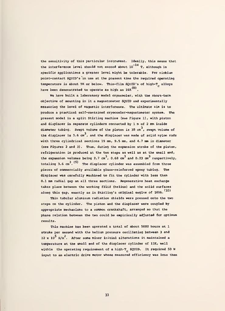
the sensitivity of this particular instrument. Ideally, this means that-14
the interference level should not exceed about 10 T, although in
specific applications a greater level might be tolerable. For niobium
point-contact SQUID' s in use at the present time the required operating
temperature is about 9K or below. Thin-film SQUID' s of high-T alloys(8)
C
have been demonstrated to operate as high as 16K
We have built a laboratory model cryocooler, with the short-term
objective of mounting in it a magnetometer SQUID and experimentally
measuring the level of magnetic interference. The ultimate aim is to
produce a practical self-contained cryocooler-magnetometer system. The
present model is a split Stirling machine (see Figure 1) , with piston
and displacer in separate cylinders connected by 1 m of 2 mm inside
diameter tubing. Swept volume of the piston is 38 cm , swept volume of
the displacer is 3.6 cm , and the displacer was made of solid nylon rods
with three cylindrical sections 19 mm, 9.5 mm, and 4.7 mm in diameter
(see Figures 2 and 3). Thus, during the expansion stroke of the piston,
refrigeration is produced at the two steps as well as at the small end,
the expansion volumes being 2.7 cm , 0.68 cm and 0.23 cm respectively,3 (9)
totaling 3.6 cm . The displacer cylinder was assembled from three
pieces of commercially available glass-reinforced epoxy tubing. The
displacer was carefully machined to fit the cylinder with less than
0.1 mm radial gap on all three sections. Regenerative heat exchange
takes place between the working fluid (helium) and the solid surfaces
along this gap, exactly as in Stirling's original engine of 1816.
Thin tubular aluminum radiation shields were pressed onto the two
steps on the cylinder. The piston and the displacer were coupled by
appropriate mechanisms to a common crankshaft, arranged so that the
phase relation between the two could be empirically adjusted for optimum
results.
This machine has been operated a total of about 5000 hours at 1
stroke per second with the helium pressure oscillating between 3 and
5 212 x 10 N/m . After some minor initial alterations it maintained a
temperature at the small end of the displacer cylinder of 13K, well
within the operating requirement of a high-T SQUID. It required 50 W
input to an electric drive motor whose measured efficiency was less than
33

25%. Thus, the actual mechanical power input was approximately 10 W.
This agrees reasonably well with the power calculated from the piston
displacement and the pressure excursion
We wish to emphasize that our cryocooler design represents only a
tentative first step toward a possible practical machine for small
superconducting devices, the realization of which seems to us poten-
tially very rewarding. We have demonstrated (1) that non-magnetic,
insulating materials such as nylon and glass-reinforced epoxy can be
used in reciprocating machines with rather long operating time, and (2)
that useful cryogenic temperatures can be maintained with very low input(12)
power , if the superconducting system is compatible with very low refri-
geration capacity.
This work is supported in part by the Office of Naval Research and
by the Naval Electronics Systems Laboratory.
34

REFERENCES
1. J. R. Davis and M. Nisenoff , International Conference on Super-
conducting Quantum Devices, Berlin (West), October 5-8, 1976.
(Proceedings to be published by Walter de Gruyter, Berlin)
.
2. J. Clarke, Proceedings of the Berlin conference cited in ref. 1.
See also Proc. 14th Int. Conf. on Low Temperature Physics 4^ 226
(North-Holland Publ. Co., Amsterdam, 1975).
3. M. McColl, et al, Appl. Superconductivity Conference in Palo Alto
(California) , August 1976 (To be published in IEEE Trans on
magnetics)
.
4. Several of these applications were described at the Berlin con-
ference cited in Reference 1.
5. N. V. Frederick, et al, IEEE Trans, on Geosci. Electronics GE-12,
102 (1974). J. E. Zimmerman and W. H. Campbell, Geophysics 40,
269 (1975).
6. D. Cohen, IEEE Trans on Magnetics MAG- 11 694 (1975)
.
7. W. M. Wynn, et al, IEEE Trans, on Magnetics MAG-11 , 701 (1975) (See
also Reference 1)
.
8. T. Fujita, et al, IEEE Trans, on Magnetics MAG-11 , 739 (1975).
9. The principle of Stirling machines with multiple expansion spaces
is described in detail by G. Prast, Philips Tech. Rev. 26, 1 (1975).
10. See for example G. Walker, Stirling-Cycle Machines, Oxford Univer-
sity Press (1973)
.
11. More details on the operation of this cryocooler and the possi-
bility of operating a SQUID magnetometer with it were given at the
Berlin conference cited in Reference 1.
12. The lowest input power requirement for any previous practical
cryocooler has been given as about 300 W. See a survey by T. R.
Strobridge, NBS Tech. Note 655 (June 1974)
.
35

•REGENERATORGAP
PISTON
Qi Rejected
Absorbed
REGENERATORHEAT CAPACITY
(Q 3= Q b for
Perfect Gas)
Figure 1. The essential elements of a Stirling machine, and the theo-
retical thermodynamic cycle (from ref . 11)
.
1 m Connecting line ^^1S_{Pushrod to
scotch yoke
Rubber
piston ring
Felt
grease ring Press fit
and cement
Piston rod to
crosshead
and crankshaft
Radiation shields
Vacuum wall —
Figure 2. Sketch of an experimental three-stage Stirling cryocooler
(from ref. 11)
.
36

«tt
Figure 3. Photograph of disassembled cryocooler. Left to right:
working cylinder, piston, displacer cylinder, two radiation
shields, and displacer. Fittings were provided for main-
taining a helium atmosphere on the non-working side of the
piston (tube at center left) , connecting a pressure transducer
(top left) , and filling the system with helium, (top center.) .
37

"Applications of Closed-Cycle Cryocoolers to Small Superconducting Devices," NBS Special PublicationSP-508 (J. E. Zimmerman and T. M. Flynn, eds.)> Superintendent of Documents, U. S. GovernmentPrinting Office, Washington, D. C. 20234 (1978), pps. 59-65.
Operation of a SQUID in a Very Low-Power Cryocooler *
J.E. Zimmerman and Ray RadebaughCryogenics Division
National Bureau of StandardsBoulder, Colorado 80303
Abstract
A point-contact Nb SQUID has been operated a total of several hundred hours
at a temperature of about 8.5 K in a low-power Stirling cryocooler with a four-
stage displacer. The system requires the order of 15 W of mechanical drive
power. Except for the drive motor, the entire unit is non-magnetic, and the
displacer and cold cylinder are made of non-conducting plastics, to minimize
ferromagnetic and eddy-current fields, which would interfere with the operation
of the SQUID when used as a magnetometer. With the system operating in the-5 -9
earth's field B , an ac interfering signal of about 10 B (i.e., -v 10 T) at
the SQUID was seen at the 1 Hz operating frequency of the cryocooler. This
signal was probably caused by rotation of the SQUID in the earth's field due to
pressure flexing of the cold cylinder, although magnetic impurities in the moving
parts would also contribute. Measurements of the complete self-generated inter-
ference spectrum, and experiments aimed at reducing interference to levels of-12
10 T and below are in progress.
We have previously published an essentially theoretical discussion of the operation of a
very- low- power superconducting device, such as a SQUID, in a closed-cycle cryogenic refri-
gerator (cryocooler) [1,2]. It was pointed out that the refrigeration capacity required for
the devices themselves is negligible, and the capacity required to cool the electrical leads
is small. On the other hand, a SQUID magnetometer, in particular, places a rigorous upper
limit on the allowable level of magnetic and mechanical interference.
It is assumed, of course, that all of the major heat loads (room temperature radiation,
and heat flow along electrical leads and support members, for example) are intercepted and
pumped out at one or more higher-temperature refrigeration points, rather than at the cold
end. In fact, in most small-device applications, it would seem that the refrigeration re-
quirement at the cold end is almost incidental, if the heat loads at the higher-temperature
points are handled efficiently. Obvious though this point is, cryocoolers are very often
described in terms of cold-end refrigeration capacity only.
In liquid-helium cryostats, higher-temperature refrigeration is provided by the helium
vapor, whose total refrigeration capacity, uniformly distributed in temperature, is about 70
times that of the evaporating liquid itself. In a cryocooler one has the opportunity, in
principle, of optimizing the distribution of refrigeration at several points between ambient
and low temperature regions. Furthermore, a cryocooler is required to cool only the device
* Contribution of the National Bureau of Standards, not subject to copyright.
Supported in part by the Naval Electronics System Command.
38

itself and not a large liquid reservoir. Thus, for two reasons, estimates of refrigeration
requirements based on experience with liquid-helium cryostats may be quite conservative.
Since there is a pervasive casual tendency to specify cryocoolers only by their refri-
geration capacity at cold end, it may be useful to illustrate this point with a hypothetical,
but fairly typical, example. A one-liter plastic liquid-helium cryostat with a single vapor-
cooled radiation shield at a steady-state temperature of 150 K might have a heat leak to the
helium, as measured by the evaporation rate, of 30 mW. Here the evaporation rate and the
shield temperature are mutually interdependent. That is, a lower shield temperature would
reduce the evaporation rate, but then the flow of cold vapor would not maintain the shield
temperature at the lower value. On the other hand, if a cryocooler were used to cool the
same one-liter volume and the same radiation shield, it could be designed to maintain the
shield at 50 K instead of 150 K. If the heat leak to the one-liter volume were primarily
thermal radiation, then it would be reduced by a factor of 81, from 30 mW to about 0.4 mW.
If there were appreciable thermal conduction as well as radiation, the comparison would not
be quite so dramatic, but still impressive.
We also described [1,2] an experimental cryocooler particularly suited for operating
very low-power high-T superconducting devices. This cryocooler was a three-stage split
Stirling-cycle [3] machine, which was operated more than 6000 hours at 1 stroke-per-second,
and reliably maintained a temperature of 13 K or less for uninterrupted periods of up to 5
weeks. Its novel features were (1) non-magnetic, non-conducting plastics for the displacer
and cold cylinder, (2) low operating power, and (3) mechanical simplicity. Solid nylon rod
was used for the displacer and commercial spun-glass epoxy ("G-10") tubing for the cold
cylinder. The input power of 50 W to an electric drive moter with about 15 W mechanical
output power was a factor of 10 or more smaller than the power requirements of any previous
machine for this temperature range, so far as we are aware. Regenerative heat exchange
occurred in the narrow radial gap between the nylon displacer surface and the inner surface
of the cold cylinder. Gap regeneration was used in Stirling's original engine in 1816, and,
being mechanically trivial, is commonly used in miniature engines described in hobbyists
magazines.
A machine similar to ours (plastic displacer, gap regeneration, and very low power) was
built several years ago by du Pre and Daniels [4]. They achieved 130 K with a two-stage
displacer and 98 K with a conical displacer. The latter may be regarded as the limiting case
of a displacer with an infinite number of stages.
The temperature maintained by our three-stage machine is well within the range of high-T
superconductors such as NbN and Nb3Sn. Practical devices have been made to operate at 14 K
and above [5].
A new four-stage displacer and cold cylinder (Figures 1, 2 and 3) were built to replace
the three-stage unit. With this modification and some minor refinements, the machine has
maintained around 8.5 K for a total of several hundred hours of operation. The four sections
of the nylon displacer were, respectively, 4.7, 9.5, 19 and 28 mm diameter and 15, 10, 12 and
12 cm long. The cold cylinder was made from sections of commercial spun-glass epoxy tubing
("G-10") with 2.4 to 4 mm wall thicknesses. The displacer sections were carefully
machined to fit the cylinder with almost no radial clearance, except for a few cm of the
39

large end where about 0.1 mm radial clearance was provided. During cooldown, differential
contraction of the nylon rods and the glass-epoxy tubes provides about one percent radial
clearance, except at the large (warm) end. This technique of fitting the displacer to the
cylinder is quite simple, and it also gives the minimum possible regenerator gap volume, which
is important for achieving minimum temperature. As in the earler model, the exact lengths of
the sections were calculated to take account of differential contraction, so as to give pre-
cise longitudinal fit in each section after cooldown. Here the fitting technique is not so
simple. The important thing is to avoid any appreciable dead volume at the small (cold) end.
Slight misfitting at the larger steps seemed to have little effect on the cold-end temperature.
Our measurements of the various components of stray heat inputs, including "shuttle
heat," reported separately [6], led us to conclude that lower temperature would be achieved by
reducing the displacer stroke. Thus, the four-stage displacer has been operated with a 7 mm
stroke, as compared to the 12 mm stroke of the three-stage model. Other operating parameters
were essentially the same for both models, namely: operating speed 1 Hz, average pressure3
0.5 MPa (5 atm), and piston displacement 38 cm . The average pressure, the speed, and the
displacer stroke could be varied considerably around these values without changing the cold-
end temperature very much. It was found that the values of these three parameters giving
lowest ultimate temperature were generally lower than the values giving fastest cooldown --
a result not entirely unexpected.
The machine was mostly operated with the cold end down. However, it was also operated
for a few hours with the cold cylinder horizontal, and also with the cold end up. In the
latter case, the steady-state temperature was about 0.2 K greater than for the other two
positions, e.g., 8.7 K instead of 8.5 K. We did not investigate the reason for this small
gravitational effect.
Temperature of the first (large) step was measured with a thermocouple, and the cold-end
temperature was measured by a helium gas bulb clamped directly to the small (1 cm diameter)
end of the cold cylinder. A simple permanently-adjusted point-contact rf-biased Nb SQUID was
clamped to the gas bulb. Low-conductivity parallel wires were used as rf coil leads, rather
than the usual copper coaxial line, in order to reduce heat leak. Temperature of the first
step stabilized at values of 180 K for average pressure 0.5 MPa to 150 K for average pressure
0.7 MPa. The lowest stable cold-end temperature was obtained at about 0.5 MPa, as noted
above.
Our present data on magnetic and mechanical interference are meager. With the SQUID
oriented North/South in the earth's magnetic field, there was a 0.5 nT ac component in the
output at the 1 Hz operating frequency of the cryocooler. This was most likely due to pres-
sure flexing of the cold cylinder, which would result from lateral inhomogeneities in wall
thickness or elastic properties. Other lower-amplitude noise components at higher frequencies4
have not yet been measured or identified. The 0.5 nT interference at 1 Hz is only about 10
times greater than typical SQUID sensitivities. If the hypothesis of pressure flexing is
correct, then this component could perhaps be reduced by a factor of 100 by correcting the
Inhomogenieties in the cylinder walls. Another factor of 100 could probably be achieved by
accurately measuring the wave shape and amplitude and subtracting it from the output. In any
40

case, this particular Interference would not so seriously affect measurements at frequencies
other than 1 Hz.
Measurements of the full self-generated Interference spectrum for the system remain to be
done. At this point we believe that a useful low-cost system can be built for magnetic mea-
surements in the picotesla range. Similar systems could be built for other device applica-
tions [2]. The Josephson voltage standard [7] seems a particularly good candidate.
Just as the point contact made Josephson devices such as SQUID'S available to everyone
who took the time to understand a simple but unfamiliar principle, the work reported here
demonstrates that superconducting temperatures are also available to everyone who takes the
time to acquire modest skill with a lathe.
References
[1] J.E. Zimmerman, R. Radebaugh and J.D. Siegwarth, "Possible Cryocoolers for SQUID Magne-
tometers," Superconducting Quantum Interference Devices and Their Applications . H.D.
Hahlbohm and H. Lubbig, eds., Walter de Gruyter, Berlin (1977) p 287.
[2] J.E. Zimmerman, R. Radebaugh and J.D. Siegwarth, "Refrigeration for Small Superconducting
Devices," Conf. German Refrigeration Society, Munich (October 1976) (in press).
[3] G. Walker, Stirling-Cycle Machines , Oxford University Press (1973).
[4] F.K. du Pre\ A. Daniels, "Gap-Regeneration Method for Stirling and Similar Cycles,"
Progress 1n Refrigeration Science and Technology, Vol. 1, Proc. XIII International
Congress of Refrigeration, Wash. D.C., (1971) AVI Publishing Co., Inc. Westport, Connec-
ticut, p 137 (1973).
[5] M. Beasley in this publication.
[6] R. Radebaugh and J.E. Zimmerman, in this publication.
[7] L. Holdeman, in this publication.
41

Plastic Piston
in Cylinder
HeliumGas
Glass Reinforced
Plastic Cylinder
First Step
Vacuum Space
AluminumVacuum Can
Radiation Shields
Cold End
Squid
Figure 1. Schematic diagram of low-power SQUID cryocooler system, not to
scale. Displacer dimensions and other data are given in text.
42
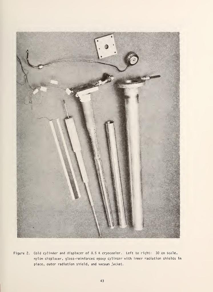
Figure 2. Cold cylinder and displacer of 8.5 K cryocooler. Left to right: 30 cm scale,
nylon displacer, glass-reinforced epoxy cylinder with inner radiation shields in
place, outer radiation shield, and vacuum jacket.
43

Figure 3. Room-temperature end of cold cylinder assembly. Clockwise from left: gas line
to working cylinder, gas-thermometer line, thermocouple wires, vacuum connection,
and rf SQUID connector.
44

"Applications of Closed-Cycle Cryocoolers to Small Superconducting Devices," NBS Special PublicationSP-508 (J. E. Zimmerman and T. M. Flynn, eds.), Superintendent of Documents, U. S. GovernmentPrinting Office, Washington, D. C. 20234 (1978), pps. 67-73.
SHUTTLE HEAT TRANSFER IN PLASTIC DISPLACERS AT LOW SPEEDS *
Ray Radebaugh and J. E. ZimmermanCryogenics Division
National Bureau of StandardsBoulder, Colorado 80303
ABSTRACT
Previous analyses of shuttle heat transfer in refrigerators with displacers have neglected
radial temperature gradients in the displacer or cylinder. Such analyses are valid when the
gas gap 1s the dominant thermal resistance. We show that with plastic materials for the
displacer and cylinder, shuttle heat transfer can be dominated by the thermal penetration
depth of the plastic when operating at low speeds. An equation is derived for the shuttle
heat transfer 1n such cases. Experimental data on shuttle heat transfer is obtained for
temperatures down to 120 K for different strokes and speeds and the agreement with calculated
values 1s good.
* Supported in part by the Naval Electronic Systems Command
45

SHUTTLE HEAT TRANSFER IN PLASTIC DISPLACERS AT LOW SPEEDS
Ray Radebaugh and J. E. ZimmermanCryogenics Division
National Bureau of StandardsBoulder, Colorado 80303
INTRODUCTION
The Stirling-cycle refrigerator described previously [1] requires no net refrigeration
power to keep a SQUID cold. The lowest temperature reached 1s the point where the total
refrigeration power 1s cancelled by various heat flows to the low temperature end. These
heat flows come from several sources, Including radiation, heat conduction down the dlsplacer,
regenerator Inefficiency, and shuttle heat transfer. Radiation heat flow to the lowest
temperature can be made negligible in most cases with good shielding. For temperatures
somewhat above 10 K the regenerator Inefficiency can be made fairly small. Thus the major
heat flow 1n much of the refrigerator Is from the conduction and shuttle processes. Shuttle
heat transfer occurs when the dlsplacer, with an axial temperature gradient, reciprocates
Inside a cylinder with a similar temperature gradient. Because shuttle heat transfer 1s a
major source of heat leak, it must be well characterized in order to optimize the design of
the refrigerator.
PREVIOUS WORK
Zimmerman and Longsworth [2] discussed shuttle heat transfer and derived an equation for
1t based on a simplified theory. Their theory contained four simplifying assumptions: (1)
properties are only weak functions of temperature, (11) heat capacity of the dlsplacer and
wall are Infinite, (111) negligible gas pressure cycling, and (1v) Interaction of axial
conduction effects 1n the dlsplacer are neglected. For square-wave motion of the displacer
they derive the equation
V Tc
(i)
for the shuttle heat transfer, where k 1s the thermal conductivity of the gas, D is the
dlsplacer diameter, S 1s the stroke length, t 1s the radial clearance, L 1s the length of the
dlsplacer, Th
1s the hot temperature, and 1Q
1s the cold temperature. For sinusoidal motion
the average temperature drop across the gas gap 1s 2/tt times that for square-wave motion.
Hence for sinusoidal motion the average shuttle heat transfer becomes
<."¥ vV (2)
More exact calculations may give different numerical doefficlents, but the functional depen-
dence of the shuttle heat loss on the various parameters will remain the same.
Harness and Neumann [3] calculated shuttle heat transfer when assumption (1v) was re-
laxed. The problem then becomes very complex and can be solved only by numerical Integration
of a second-order differential equation. Their results for the total heat flow differ from
46

that of adding the static heat conduction down the displacer to the simple shuttle heat
transfer equation given above. The difference ranges from 5 to 40%, depending on various
parameters, and is not always of the same sign.
As far as we know, attempts to solve the shuttle heat transfer problem with any of the
other three assumptions relaxed has never been done. However, we were concerned that assump-
tion (ii) was not satisfied when the displacer and wall materials were of plastic and their
operation was at the low speed of about 60 rpm. When the heat capacity of the displacer and
wall are assumed to be infinite, radial temperature gradients are thus neglected. In high-
speed operation little heat is transferred across the gas gap in each cycle. As a result,
the surface temperature of the displacer and wall remain nearly constant in time and the
assumption (ii) is satisfied. Temperature cycling of the surface does become important at
low speeds. The use of plastic materials instead of metal increases the amount of tempera-
ture cycling because the lower thermal conductivity decreases the thermal penetration depth.
THEORY
In order to keep the problem from becoming too complex, we first make the following
assumptions: (i) properties are nearly constant with temperature, (ii) thermal resistance of
the gas gap is negligible, (iii) the effect of gas-pressure cycling is neglected, i.e.,
regenerative action is perfect and heat capacity of the gas in the gap is negligible, (iv)
interaction of the axial conduction effects in the displacer and wall are neglected, and (v)
motion of the displacer is sinusoidal.
The shuttle heat transfer is just the net enthalpy flow resulting from the motion of the
displacer. Its temperature is higher during the hot-to-cold motion than during the reverse
motion so enthalpy is transported toward the cold end. The net enthalpy flow is just equal
to the heat transferred to the displacer during one-half the cycle over a length equal to the
stroke. To evaluate this heat transfer we first let the wall have infinite heat capacity so
that it has no temperature cycling. We relax this condition later. Because of assumptions
(ii) and (iii) above, we can say that the surface of the displacer takes on the temperature
of the wall adjacent to it at any moment in time. The sinusoidal motion of the displacer
then causes a sinusoidal temperature fluctuation of the surface, provided the axial tempera-
ture gradient is constant over the distance of the stroke. The problem of sinusoidal tem-
perature fluctuations on the surface of a semi-infinite solid is commonly treated in texts on
heat conduction. Schneider [4] treats such a problem and the total heat transferred during
one-half of the cycle is given as
Q = 2AAT /kTC , (3)
where A is the surface area, AT is the peak of the temperature fluctuation, k is the thermal
conductivity of the displacer, C is its specific heat per unit volume, and w is the frequency
of oscillation. For n cycles per second o» = 2™. Now A = ttDS and AT = (dT/dx)(S/2). Thus
the heat transfer during one-half cycle and the net enthalpy flow per cycle become
47

Q = DS2 SiU/I5t
( 4 )
If the wall material has the same specific heat and thermal conductivity as that of the
displacer, then AT will be just one-half of t\
transfer with n cycles per second then becomes
displacer, then AT will be just one-half of that considered above. The average shuttle heat
ft- timlnvW /»rkC _ DS
2(dfl /rmkC
Qs
- (l/2)nDS [dYjW-^7 " —[d^J V—mrkC (5)
As before, the functional dependence should be correct, but more exact calculations may give
slightly different numerical coefficients.
For a thermal conductivity independent of T we can write dT/dx = T, - T_ /L. The
primary difference between this shuttle heat transfer and that derived by Zimmerman and
Longsworth is the vn dependence in the present calculation. Thus at low speeds the thermal
resistance of the solid material limits the shuttle heat transfer, whereas at higher speeds
the thermal resistance of the gas gap limits the shuttle heat transfer and Eq. (2) must be
used. For intermediate speeds we derive the total shuttle heat transfer by considering the
two thermal resistances to be in series. Hence
i/0s
« i/09s
+ i/0s
s, (6)
where tip and ?)
sare the shuttle heat transfers limited by the gas gap and by the solid
material, respectively.
Equation (5) will be valid as long as the radius of the displacer and the wall thickness
is somewhat greater than the thermal penetration depth in the material. The thermal penetra-
tion depth X is defined as that depth where the amplitude of temperature fluctuation is 1/e
of that at the surface and is given approximately by [4]
X = \/k/rmC , (7)
where k/C is just the thermal diffusivity. Table 1 shows values of k, C, and X for nylon at
various temperatures with n = 1 Hz. Values for k are from Ashworth, et al . [5], and values
for C are estimated from two different sources [6,7]. The specific heat and thermal con-
ductivity of G-10 glass-reinforced epoxy is roughly the same as that of nylon [8]. From the
penetration depths given in Table 1 we see that finite size effects can be neglected in most
practical cases.
48
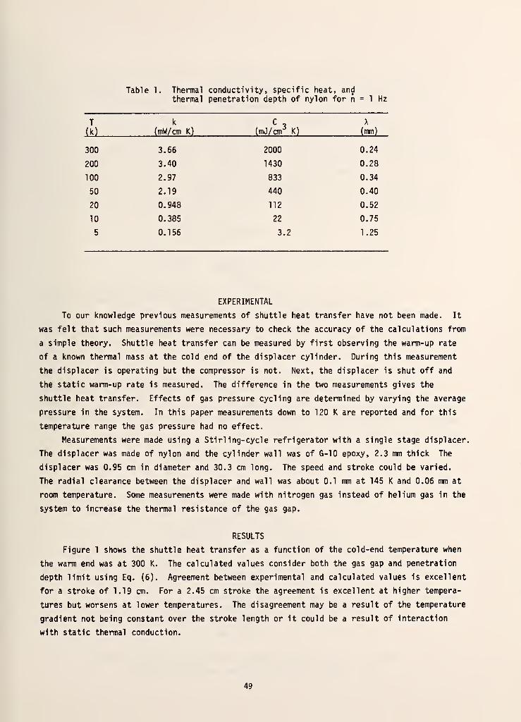
Table 1. Thermal conductivity, specific heat, andthermal penetration depth of nylon for n = 1 Hz
T
(k)
k
(mW/cm K)
C3
(mJ/cnr K)
X
(mm)
300 3.66 2000 0.24
200 3.40 1430 0.28
100 2.97 833 0.34
50 2.19 440 0.40
20 0.948 112 0.52
10 0.385 22 0.75
5 0.156 3.2 1.25
EXPERIMENTAL
To our knowledge previous measurements of shuttle heat transfer have not been made. It
was felt that such measurements were necessary to check the accuracy of the calculations from
a simple theory. Shuttle heat transfer can be measured by first observing the warm-up rate
of a known thermal mass at the cold end of the displacer cylinder. During this measurement
the displacer is operating but the compressor is not. Next, the displacer is shut off and
the static warm-up rate is measured. The difference in the two measurements gives the
shuttle heat transfer. Effects of gas pressure cycling are determined by varying the average
pressure 1n the system. In this paper measurements down to 120 K are reported and for this
temperature range the gas pressure had no effect.
Measurements were made using a Stirling-cycle refrigerator with a single stage displacer.
The displacer was made of nylon and the cylinder wall was of G-10 epoxy, 2.3 mm thick The
displacer was 0.95 cm in diameter and 30.3 cm long. The speed and stroke could be varied.
The radial clearance between the displacer and wall was about 0.1 mm at 145 K and 0.06 mm at
room temperature. Some measurements were made with nitrogen gas instead of helium gas in the
system to increase the thermal resistance of the gas gap.
RESULTS
Figure 1 shows the shuttle heat transfer as a function of the cold-end temperature when
the warm end was at 300 K. The calculated values consider both the gas gap and penetration
depth limit using Eq. (6). Agreement between experimental and calculated values is excellent
for a stroke of 1.19 cm. For a 2.45 cm stroke the agreement is excellent at higher tempera-
tures but worsens at lower temperatures. The disagreement may be a result of the temperature
gradient not being constant over the stroke length or it could be a result of interaction
with static thermal conduction.
49
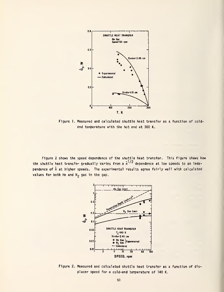
08
06
S.£ 0.4
02
11
SHUTTLE HEAT TRANSFER
He Gas
Speed=54 rpm
Stroke-2 45 cm
• Experimental
— Calculated
T, K
Figure 1. Measured and calculated shuttle heat transfer as a function of cold-
end temperature with the hot end at 300 K.
Figure 2 shows the speed dependence of the shuttle heat transfer. This figure shows how•1/2
the shuttle heat transfer gradually varies from a n ' dependence at low speeds to an inde-
pendence of n at higher speeds. The experimental results agree fairly well with calculated
values for both He and N« gas in the gap.
in•0
02-
0.01
"I I I I 1 I IT] 1 1—I MillHe Gas Limit
1
Stroke=2 45 cm
:"J £ lExperm^Ul
— Calculated
_i—i i i i i il
5 10 20
SPEED, rpm
50 100
Figure 2. Measured and calculated shuttle heat transfer as a function of dis-
placer speed for a cold-end temperature of 140 K.
50
We conclude that at least for the parameters used in this experiment, shuttle heat
transfer can be estimated to within about 15% by combining the two expressions given by
Eqs. (2) and (5) in the manner prescribed by Eq. (6). This imples the two thermal resis-
tances are in series and that the necessary simplifying assumptions can be met in practice.
Optimization of the parameters of the Stirling refrigerator can then be carried out analy-
tically. In the tests done here the shuttle heat transfer was about five times the static
conduction for a stroke of 1.19 cm. These results show that a more optimum design would have
a shorter stroke and larger diameter to minimize the total heat transfer. Because k and C
3are proportional to T at lower temperatures, the calculated values may not be in quite so
good agreement with experiment at such temperatures unless Eq. (5) 1s Integrated properly
between T. and T . Measurements down to about 5-10 K would be useful and are in progress.
REFERENCES
[1] J.E. Zimmerman and Ray Radebaugh, this publication.
[2] F.J. Zimmerman and R.C. Longsworth, Adv. Cryog. Eng. 1_6, 342 (1970).
[3] J.B. Harness and P.E.L. Neumann, Proc. Int'l Cryog. Eng. Conf., 5th (1972) p 97.
[4] P.J. Schneider, Conduction Heat Transfer , Addison-Wesley, Cambridge, MA (1955) p 276.
[5] T. Ashworth, J.E. Loomer and M.M. Kreitman, Adv. Cryog. Eng. 1_8, 271 (1973).
[6] W. Reese and J.E. Tucker, J. Chem. Phys. 43, 105 (1965).
[7] B. Wunderlich, Rensselaer Polytechnic Institute Report No. TR-17, Office of Naval Re-
search Contract Nonr-591(19) (1968).
[8] J. A. Barclay, S.S. Rosenblum and W.A. Steyert, Cryogenics 16, 539 (1976).
51

XV International Congress of Refrigeration, Venice, Italy (September, 1979).
ANALYSIS OF REGENERATOR INEFFICIENCY FOR STIRLING-CYCLE *
REFRIGERATORS WITH PLASTIC DISPLACERS
Ray RadebaughThermophysical Properties Division
National Bureau of StandardsBoulder, Colorado, U.S.A.
1. INTRODUCTION
One of the major sources of heat flow to the cold end of a Stirling-cycle re-
frigerator operating below about 15 K is due to regenerator inefficiency. Manyanalyses and experiments have been performed previously, but all have dealt withthe case of negligible thermal resistance internal to the regenerator material.
Recently temperatures as low as 3 K have been reached with a Stirling-cycle refrig-erator that uses fiberglass-epoxy for all the low temeprature parts. Ill Plasticregenerators - displacers are necessary for operation of SQUID magnetometers, butthe internal thermal resistance of the plastic dominates the behavior of the re-generator. This paper analyzes the inefficiency of such regenerators and comparesthe results with experiment. In addition the effect of heat flow to the cold endcaused by non-ideal gas effects ere considered.
2. DEVELOPMENT OF MODEL
In all of the refrigerators built to date with plastic displacer - regener-ators, the regenerator is the annular gap between the displacer and the walls.For the 3 K refrigerator an additional annular gap outside the first cylinder wasprovided /I/. The model we use to describe the regenerator behavior is one of a
seal-infinite solid with the surface undergoing a cyclic temperature variation.In addition there is a temperature gradient parallel to the surface. Nusselt 111
has considered the case of regenerators which have a finite conductivity normal to
the gas flow and zero conductivity parallel to the gas flow. Of the cases con-sidered by Nusselt this one is the closest to our situation except that the thermalconductivity and specific heat are strong functions of temperature. The completeset of second-order partial differential equations then become so complex thattheir solution would require considerable computer time.
In order to simplify the equations governing the regenerator behavior we makethe following assumptions:
(1) temperature variation at the surface is sinusoidal,
(2) surface temperature is the gas temperature,
(3) gas volume in regenerator is negligible, compared with expansionvolume,
(4) the sinusoidal heat flow is only in the radial direction,
(5) the expansion and compression space are isothermal,i.e., the Schmidt analysis 131 can be used,
(6) various heat flows to the expansion space are independentof each other.
Assumptions 2-4 appear to be quite reasonable in the range of the present ex-periments. Assumption 1 is made since it greatly simplifies the calculations eventhough the mass flow of gas through the regenerator is only approximately sinu-soidal. For a sinusoidal temperature variation at the surface, the heat flow into(or out of) the regenerator during one half the cycle is /4/
Q - 2AAT /kC„/2Trn . (1)o v
For an annular gap heat can flow both outward and inward in the solid material andso the surface area A should be 2irDL. The amplitude of the temperature variation
52

decreases with the distance from the surface. The thermal penetration depth X is
defined as
X - /k/C *nv
(2)
where the amplitude is 1/e of that at the surface. Thus the model considered is
valid only for wall thickness, d > X.
The validity of assumption 2 and of using the semi-infinite solid model for
d - 3 mm is shown in Fig. 1 which compares the AT of the surface of the seml-
10>
CM \~3
:h
10"=-
io-2k
10
= 1 1 1 1|
1 1 I 1 1 1 1 1|
1 11 =
T = 5K ~
- G-10 THERMAL PENETRATION^."
Z"^^^--*"~"
G-10 3mm WALL THICKNESSX =—5*""" ^ -
-LEAD 3mm WALL\ _ ^_ \ _ —
<^'
^^ TURBULENT FLOW^
2 ^^LAMINAR FLOW "=
- .^""HELIUM GAP = 0.1mm 2
=-
^_^—-—^^LEAO THERMAL PENETRATION -
..!.. I i i 1 i i I i i I i i 1 i tl-3
0.5 1.0 10 50
SPEED, Hz
Fig. 1. A comparison of the AT times area per unit heat flow as a functionof speed in the gas and in the solid regenerator.
Infinite solid with that due to a wall 3 mm thick which has X « » and with the ATacross the helium gas. For speeds of 1 & and above the dominant AT is due to thefinite thermal penetration depth of the G-10 fiberglass epoxy. The thermal penetra-tion depth Increases rapidly as the temperature is lowered and at 5 K is X = 2.1 mmfor n - 1 Hz.
Heat flow into the regenerator comes from decreasing the temperature of thehelium gas. The amplitude AT is found by equating the heat flow from the gas,
SdT, with that in the solid, i.e., Eq. (1). After some rearranging of terms, we
AT mC (dT/dx) /4D/irkC ,/2nP v
(3)
Because of assumption 4 we take dT/dx to be that caused by conduction heat transfer.An iterative procedure is required to find AT since the average temperature usedto calculate dT/dx depends on AT . At the cold end the regenerator temperature os-cillates between T and T + 2AT .° The calculated AT
Q usually is less than about 0.7K for T » 5 K. The incoming gas then enters the expansion space at an averagetemperature of 1 + AT and thus causes an effective heat flow of
" naC ATxeg p c
n(mC ) (dT/dx)/4D/rrkC /2np v (4)
53

The term mC Is found from an integration over the crank angle using the Schmidt
analysis. p
The overall refrigerator behavior is calculated by using the heat balanceequation
<ref \et +^rad
+ % + Q.+ Qfrict
+<>reg
+ % (5)
The shuttle heat flow, Q has been calculated previously 15/ for plastic displacers.
The term Q occurs in a Son-ideal gas because the total enthalpy flow from T to T
is greater than enthalpy flow in the reverse#direct ion due to the pressure variations.
To calculate the minimum temperature we set Qnet " °* '^ne weakest assumption is 5,
since X for helium at O.lMPa is only 0.2 mm at 5 K, but it increases to 7.7 mm at
300 K. Thus nearly adiabatic behavior occurs at 5 K and the Schmidt analysis for
Qref would be too high by possibly a factor,or two. ^ Since the Schmidt analysis is
also used to find the mass flow, the terms Qre_ and Qh would also be t<jo high byroughly the same factor. For Q t
and T <°7 K the terms Qr and Qy dominatethe others so assumption 5 may be satisfactory when calculating the minimum tempera-ture.
3. COMPARISON WITH EXPERIMENT
Calculated behavior is compared with the experimental behavior of the re-frigerator described by Zimmerman and Sullivan 111 . The calculations for theminimum temperature were done by setting Qnet " and calculating the requiredregenerator length for different expansion apace temperatures. Because of theisothermal assumption the calculations for Qjj cannot be done in the two fluidregion reached in the experiments. The term % increases rapidly as liquid isformed but only 32 liquid was produced in the experiments. Thus extrapolation tothe lower temperatures should be reasonable. Figure 2 shows calculated regenerator
20
1 1 T 1
T u=12
1 1
.OK
-
10
5
2
o o*\
£ \ \
4 ~—'—^.\ ,9kPa I,
^ ">-C^ Y
-\ v^ * \
- x \^s^-19kPa}
\ 47kPa^\^S>,,
Pmean
!86kPa
-
\1 _ Vs.skX^ 80kPa —
'\ -
.5 i 1 1 1 \ 1
-
4 5 6 7 8 9 10
TEMPERATURE, K
Fig. 2. Calculated regenerator lengths as a function of the expansion spacetemperature. All calculated curves are for Tu - 12 K except thelowest curve. The experimental points at L - 12 cm are for Tu - 8.6
12 K. P„._ - 80kPa.
54

8.6lengths for different expansion space temperatures and pressures. With TuK, P -27 kPa, and L - 12 cm the experimental result of 3.1 K is consistent
withmthe extrapolated value from calculations. For Tu - 12 K, Pmean 80 kPa, and
L - 12 cm the calculated value of 4,4 K is in good agreement with the experimental
value of 4.1 K. The optimum pressure for T - 4 K and Tu - 12 K is about 27 kPa
according to Fig. 2. The optimum diameter and stroke are about 6 mm and 10 mmrespectively for a displaced cold volume of 0.3 cm .
Figure 3 shows a comparison of Qnecfor experiment and theory. The minimus
temperatures agree well but the agreement in Qnet deteriorates as Qnet increases,
presumably due to the adiabatic behavior. Figure 4 shows the magnitude of the
various heat flow terms. Note that Qreg a n P from Eq. (4), since m a P.
Figure 4 shows only a slight deviation from P 2 behavior becaus^ of the pressuredependence of Cp
. For Cp independent of temperature Qreg a T for T = 5 K.
30
25-
20-
10
5 -
Pmean=
80 kPa
Tu
= 8.7 K
' O EXPERIMENT
± j_4 5 6 7
TEMPERATURE, K
Fig. 3. A comparison of the theoretical and experimental net refrigerationpowers as a function of temperature.
4. DISCUSSION
• . • 3/2_2Because Qre£ a nP and Qreg a n T> we see immediately the advantage of using
low pressures and low speeds to improve the overall performance of the lowtemperature stage where Qreg becomes large. Further improvements in theregenerator should be directed toward Increasing Cy but keeping k smallto prevent an increase in Qcond - The term Q^ is independent of the regeneratorlength and so it can easily dominate ^ the heat flow for long regenerators. Fig. 4shows that Qh is always larger than Qreg for L - 12 cm and that Qg has a similarpressure
(dependence. The refrigerator performance should improve if He were used
because Qg would be reduced. The model discussed here appears to predict theminimum temperature to within about 10Z. Thus for Qnet = ° tnis model c*° De usedto optimize the design of such refrigerators.
55

20
5-
0.5
0.2
0.1
T I I I I I I I 1 1 I I I I I
J »'''
Fig. 4. Behavior of the various heat flow terms as a function of pressure
for L - 12 cm.
<frict
;net
?rad
?ref
reg
NOMENCLATURE
surface area for heat transfer
specific heat of helium at constant pressure
volumetric specific heat of the regenerator material
diameter of the annular gap in the regenerator
thermal conductivity of the regenerator material
length of the regenerator
total helium mass flow into the expansion space
operating speed of refrigerator
pressure of helium gas
cumulative heat transfer
heat transfer rate to the expansion space due to conduction
heat transfer rate to the expansion space due to friction
heat transfer rate to the expansion space due to enthalpyimbalance*
net heat transfer rate to the expansion space
heat transfer rate to the expansion space due to radiation
total refrigeration rate in the expansion space
effective heat transfer rate to the expansion space due to regener-ator inefficiency
56

Q_ heat transfer rate to the expansion space due to shuttle transfer/5/
T temperature of the expansion space
Tu
temperature of the hot end of the regenerator
ATQ
half-amplitude temperature variation of the regenerator surface
dT/dx temperature gradient in the regenerator in the direction of gas flow
A thermal penetration depth due to surface temperature variations
REFERENCES
*Work supported by U.S. Naval Air Systems Command. Contribution of the U.S.Government, not subject to copyright.
1. J. E. Zimmerman and D. B. Sullivan, "A Milliwatt Stirling Cryocooler for Temp-eratures Below 4 K", Cryogenics, March (1979), to be published; D. B. Sullivanand J. E. Zimmerman, "Very-Low-Power Stirling Cryocoolers Using Plastic andComposite Materials", these proceedings, and references cited therein.
2. W. Nusselt, Z. Ver deut. Ing. 71, 85 (1927), and M. Jakob, Heat Transfer, vol.II. J. Wiley & Sons, New York (1957), p. 288.
3. C. Walker, Stirling-Cycle Machines, Clarendon Press, Oxford (1973), p. 24.
4. P. J. Schneider, Conduction Heat Transfer, Addison-Wesley, Cambridge, MA(1955), p. 280.
5. R. Radebaugh and J. E. Zimmerman, "Shuttle Heat Transfer in Plastic Displacersat Low Speeds", NBS Special Publication 508 (1978), p. 67. Available from U.S.Government Printing Office, Washington, D.C. 20434.
ANALYSE DE L'INEFFICACITE DU REFENERATEUR DES REFROIDISSEURS A CYCLE-STIRLING AVECDEPLACEUR EN PLASTIQUE
SOMHAIRE: La source majeure de trans ferts therm iques dans un refroidisseur a
cycle-Stirling fonctionnant a moins de 15K environ, provient de l'inefficacite" durdgenerateur. Toutes lea experiences et analyses precedentes de l'inefficacite' ont
6t6 effect uees dana le caa d'une resistance thermique interne negligeable du materiaudu rfgenerateur. Dans le cas du refroidisaement d'un magnetometre SQUID, les
organea baaae-temperature du refroidisseur sont en plastique. Done, la resistancethermique interne eat la resistance dominants. Cet expose examine le transfer t ther-mique <JQ a l'inefficacite du regenerateur loraque les materiaux sont a bassediffusion thermique. Dans un tel cas, le transfert de chaleur eat proportionnel a
n 3/2 p2( od n e8 t ia vitesse et P la pression de l'helium gazeux. Du fait que
le taux de refroidissement est proportionnel a nP, une reduction de la vitesse et
ce la pres8ion r6duit la temperature minimum jusqu' a ce que le transfert thermique
de va-et-vient, proportionnnel a rr'^, et le transfert thermique de conduction,deviennent importants. Une comparaison avec lea result at s experiment eux a des
temperatures de l'ordre de 3K, sera fnurnie.
57

Cryogenics 19 (1979), pps. 170-171
A milliwatt Stirling cryocooler for temperatures below 4 K
J.E. Zimmerman and D.B. Sullivan
We have built a single-stage, twin-piston Stilling machine'
producing several mW of refrigeration at temperatures in
the range of 3 to 4 K, and rejecting 50 to 1 00 mW at
temperatures of 8 to 14 K. The working fluid is helium at
subatmospheric average pressure. During operation, several
mm 3of liquid helium collects in the dead space at the cold
end, and is present throughout the operating cycle. Thusthe operating temperature is essentially the equilibrium vapour
pressure of helium at the average pressure - for example,
3.1 K was achieved with an average pressure of 0.027 MPa.
and 4.0 K with an average pressure of 0.08 MPa. The hot
end temperatures were 8.6 K and 12 K respectively.
The cold parts of the unit shown in Fig. 1 consist of twoconcentric pistons and a stationary outer cylinder, all three
members being made of commercially available spun-glass
epoxy 'G-10' rod and tubing requiring no machining by us.
Small radial clearances and large length-to-diameter ratios
prevent significant gas leakage between the ends of the pistons
at room temperature. Thus, the working fluid provides gas
lubrication between adjacent surfaces, and no solid sliding
seals (ie piston rings) are required. The two pistons are
driven 90° out of phase, with a stroke of 1 cm. by
connecting rods and a crankshaft (not shown) at roomtemperature. The latter are enclosed in a metal housing
(~ I t volume) which is filled with helium gas to the
desired pressure. The only moving seal required is an
O-ring around the crankshaft end which extends outside
the housing to an electric drive motor. Owing to the reducedviscosity of helium at low temperature, there should be
little pressure drop across the regenerator gaps so the
pressures in the expansion and compression spaces should
be essentially equal at all times. In principle the motor could
also be enclosed in the metal housing and no seals at all wouldbe necessary. Since there are no sliding seals on the pistons,
the average pressure in the cylinders is identical to that in the
upper housing. Most of our data were taken with an
operating speed of 1 Hz.
For the experiments reported in this note we maintained the
hot flange on the upper cylinder at temperatures in the range
of 8 to 14 K by means of a weak thermal link to a liquid
helium bath and an electrical heater mounted on the hotflange. The temperature of the hot flange was controlled
simply by varying the heater power. The boil-off rate fromthe helium bath was used as a measure of the heat input to
the system and, in particular, we used changes in the boil-off
rate to estimate the heat ejected from the hot end of the
refrigerator during operation.
The authors are at the Electromagnetic Technology Division,
National Bureau of Standards, Boulder, CO 80303. USA. Received9 January 1979.
As shown in Fig. 1, we incorporated a pair of universal
joints in the central piston rod at the level of the comp-ression space. This allows the lower part of the piston to
centre itself in the cylinder. Without this feature, slight
misalignment of the cylinder surfaces above and below the
compression space caused those surfaces to bear against the
sides of the piston. The associated frictional heating
degraded the expected performance considerably.
Another feature, which may be important, shown in Fie. I
.
is the 'stationary insert' around the lower piston. This liiseri
is a piece of the same material as the upper piston. Having
equal annular gaps at both the inner and outer surfaces of
the insert provides two parallel paths for fluid (low between
the expansion and compression spaces, giving a total area
Toroom temperoture
connecting rods and cronkshaft
W>/>////S//A
Outer cylinder
16 mm od
Clearances -30>»m
. Upper piston (onnulor)
-12 mm od
Universol joints
-Hot end flange
- Compression space
-Lower piston
-6mm didmeter
Stationary insert
- Regenerator gops
~30^m
Eipantian space
.Cold end
Fig. 1 Sketch of single-stage Stirling cryo-cooler with approximatedimensions
58

Fig. 2 Temperature vs time of the cold end with the cryocooler
stopped at maximum expansion (lower piston 'up ) bnd minimumexpansion (lower piston 'down')
for regenerative heal exchange three times the area of the
inner gap alone. At the 1 Hz operating speed, we estimate
that heat diffuses into the material less than 1 mm, so
effectively the insert provides three times the regenerator
heat capacity. In order to analyse the effectiveness of this
particular feature, one needs to know the heat capacity and
thermal conductivity of the material, which we have measured
and will report separately.
With the upper end temperature at 8.7 K, the refrigerator
maintained a temperature of 4 K at an operating pressure of
0.08 MPa. but there was some reserve cooling capacity. The
operating temperature was limited by the pressure of the
liquid phase. Heat was added at the bottom end to
determine the reserve cooling capacity. The system maintained
liquid helium at 4.0 K up to a heat input of 4 mW at which
point the system reverted to single phase gas operation. At
9 mW input power the temperature rose to 5.5 K. The
Carnot coefficient for the cooler is 4/(8.7-4) = 0.85. Fromchanges in the helium boil-off rate, we estimated that the
heat ejected at the hot end is about 50 mW. Thus the actual
refrigeration of 4 mW at 4 K is a reasonable fraction of the
theoretical cooling power (50 mW x 0.85 = 42.5 mW).A calculation of the work input yields a number of the same
order as the heat ejected, but not much information can be
elicited from this since the two phase nature of the
refrigerator operation complicates the analysis.
Fig. 2 shows two separate warming curves for the cold end
of the refrigerator, recorded immediately after the drive
motor was switched off. These demonstrate the presence
of liquid helium in the system. The temperature rises gradually
at first since the evaporation of the liquid increases the
overall system pressure. After several minutes the temperature
increases more rapidly, indicating evaporation of the last
bit of liquid. The total quantity of liquid helium present
in the system can be estimated from the pressure change
during the slow portion of warm-up of the bottom end and
comes out to be — 0.02 cm 3. The two curves correspond to
stopping the refrigeration cycle at two different positions
separated by 180°. The first portions of the curves are similar
in shape although the temperatures are different. The time
interval required for all the liquid to evaporate varies
because a different quantity of liquid is present during each
part of the cycle. The variation in slope beyond the break
point indicates different heat capacities at the bottom end.
that is, if the bottom piston is in its uppermost position then
the heat capacity of the extra vapour reduces the warming
rate. This is a clear indication that the heat capacity of the
vapour in the expansion space is significantly greater than
that of the G-10 epoxy. the implication being that the
additional channel for regenerative heat exchange provided
by the stationary inset may be an essential feature.
We believe this is the first time that a Stirling machine
operating as a refrigerator has been shown to liquefy the
working tluid (helium or any other gas), and the temperature
achieved is about a factor of two lower than has been reporled
previously for small Stirling. Gi fiord- McMahon. and
Vuilleumier machines.3 A machine of this t\ pe appears to
be a practical alternative to a Joule-Thomson expansion
system for the final stage of a small helium liquefier or
cryocooler.
The heat load that our particular machine would impose on
the higher temperature stage (at 8 to 14 K. for example), is
low enough that the total system should require an order
of magnitude lower mechanical power input than any
existing small cryocooler.
This work was supported by the Naval Air Systems Command
References
1 Walker, Ci Slirlinp-Cvclc Machines Oxford University Pross
(1973)
2 Zimmerman. J.E., Rynn. T.M. NBS Special Publication
SP-508. National Bureau of Standards (1977)
59

"Future Trends in Superconductive Electronics," (B. S. Deaver, Jr., C. M. Falco, J. Harris, and S.W. Wolf, eds.) AIP Conference Proceedings Number 44, New York, American Institute of Physics (1978),pps. 412-420.
CRYOCOOLERS FOR SUPERCONDUCTIVE ELECTRONICS*
J. E. ZimmermanCryogenics Division
National Bureau of StandardsBoulder, Colorado 80303
ABSTRACT
Superconductive electronic devices are generally operated andwill continue to be operated in liquid-helium cryostats. Appropriatesmall closed-cycle cryocoolers for these devices do not exist.Development of cryocoolers, including efficient use of conventionalgas refrigeration cycles and innovative thoughts on new and unconven-tional methods, could greatly enhance the usefulness of small-scalesuperconductive electronics. Large cryocoolers are already well-developed and can be adapted to the requirements of large-scalesystems, such as computers, requiring a watt or more of refrigeration.
INTRODUCTION
In this paper I will refer repeatedly to two sources 1*2
. Ref.1 is the proceedings of a 1977 conference on "Applications of Closed-cycle Cryocoolers to Small Superconducting Devices," and is publiclyavailable. Ref. 2 is the proceedings of a 1973 conference on "Closed-Cycle Cryocoolers," and is available for "limited distribution." Athird significant source of information and speculation is theproceedings of the 1975 Navy Study on Superconductive Electronics. 3
Other useful and readily available references are the proceedings of
the 1976 SQUID conference" and the proceedings of the 1976 NATOstudy on small superconducting devices 5
.
This author's demonstrated qualifications as an authority oncryocoolers consist of his having built (1) in 1949, a Simon single-expansion helium liquefier, a mechanism which at the same time wasmade obsolete by the Collins Helium Cryostat, (2) a few years later,a cyclic magnetic refrigerator for temperatures down to 0.1K, a
machine which was immediately replaced by the helium dilution refrig-erator, and (3) recently, a laboratory-model Stirling cryocoolerspecially adapted to operate a SQUID magnetometer. The trend estab-lished by the earlier work, probably has been reversed by the recentachievement, since Stirling machines are now being extensively de-veloped both for pumping heat and for doing work, and this conferenceis evidence that the SQUID and other superconductive devices are seenas having great future potential. In fact, it should also be pointed
Contribution of the National Bureau of StandardsNot subject to copyright.Support in part by the Office of Naval Researchand the Naval Air Systems Command
60

out that cyclic magnetic cooling systems are currently being develop-ed by Steyert and others for temperatures between 1 and 300K, and it
is suggested below that the single-expansion process of liquefyinghelium may still be of some use in certain systems (p. 81 and p. 49,ref. 1).
Very few closed-cycle cryocoolers are now in use, or have everbeen used, to operate superconducting devices. The reason for thisbecame evident in 1947 or shortly thereafter, when the Collins HeliumCryostat became generally available. This machine was advertised andsold as a "cryostat", a device for maintaining a constant low temper-ature. Very quickly it became obvious that the machine was morecost-effective if used not as a cryostat but as a liquefier, forservicing any number of separate small liquid-helium evaporativecryostats.
ESSENTIAL HEAT INPUTS INTO CRYOSTATS
With only a few isolated exceptions, (e.g. Hartwig. p. 135, ref.
1) liquid-helium cryostats have been used for all research in super-conductivity and superconductive devices up to the present. Now,however, the beginning of change is apparent. As superconductingdevices are found to be useful for a variety of purposes unrelatedto low-temperature physics, users are searching for ways of reducingthe cost and inconvenience of liquid-helium cryogenics. One approachis to make dewars larger and more efficient, with hold times of theorder of 10
3 to 101
* hours (e.g. the 180-liter VLF SQUID cryostat of
Dinger et al. , with a hold time of 100 days 6, the 800-liter Infrared
Astronomy Satellite (IRAS), with a projected hold time of one year ,
and a similar 800-liter satellite for the Stanford relativity experi-ment, projected to operate one year in orbit at 2K 8
. More indicativeof the nature of things to come, we hope, are the systems in which a
cryocooler is incorporated into a medium-sized liquid-helium dewar to
cool one or more radiation shields and greatly reduce the evaporationrate. Temperatures well below 20K can be maintained with availablesmall commercial coolers. Black-body radiation at 20K is only 9.1mW/m2
, and if this figure can be reduced by a factor of 100 by the
use of highly reflecting surfaces, giving 91uW/m2, the corresponding
evaporation rate due to radiated heat is 0.0031 Jl/day-m2
. A sphericalcontainer with a surface area of lm2 would hold 95 liters, giving a
time of 3 x lO1* days (80 years) for complete evaporation. In most
practical cases, with a radiation shield at 20K and a helium bath at
4K, the main heat input will be conduction along mechanical supportsand electrical leads, but even so, the heat leak can in principle be
made very small. If a 95-liter container is supported by spun-glasscords, 10 cm long, calculated to withstand 100 G loading in
three orthogonal directions (six cords) , and assuming a total
61

mass twice that of the helium itself, the heat leak is calculated to
be 2mW, giving a hold time somewhat less than 4 years (40 years for
10G loading). The enthalpy change of helium between 4 and 20K is
about 4 times the heat of vaporization, so if the vapor can be used to
cool the supports, this evaporation rate might be reduced consider-ably, at the expense of geometric complexity. Size of electricalleads depends upon the particular devices in the cryostat. Let us
consider (as we often do) an rf SQUID and suppose that the rf line to
it is a thin-film stripline with a parallel dc resistance of 0.1ft
between 4 and 20K. Invoking the Wledemann-Franz law leads to a heatleak of about 45 WW, which is smaller than any of the other heatleaks calculated above.
This exercise in arithmetic is highly idealized, but it doesindicate the possibility of greatly reducing the evaporation rate ofliquid helium by using a cryocooler in a carefully-designed system.A 70-liter cryostat incorporating a cryocooler to maintain the innerradiation shield at 15K has been built by a commercial firm (W.
Goree, private communiation) . This system demonstrated a hold timegreater than one year (0.19£./day evaporation rate). The heat leakinto the helium, about 5.5 mW, was calculated to be due almost en-tirely to the 75 mm-diameter stainless steel neck tube, which pro-vided easy access to the helium bath and also served as mechanicalsupport for the reservoir.
Conventional liquid-helium cryostats, such as those mentionedabove, without liquid-nitrogen jackets, typically evaporate from oneto several liters per day. One liter per day indicates a heat inputinto the liquid of 30 mW. The total enthalpy change of the vaporbetween 4 and 300K is roughly 70 times the heat of vaporization. Thecooling capacity of the vapor, proportional to the specific heat Cp,is nearly independent of temperature over most of the range. This is
not, in general, the optimum distribution of cooling capacity vs.
temperature. A closed-cycle cryocooler with the optimum distributionis therefore, in principle, more efficient than an evaporative cryo-stat. Related to this is the important point that, for many smalllow-power superconducting devices, the lion's share of the coolingcapacity is required at higher temperatures to intercept heat radia-ted and conducted from room temperature. To specify the performanceof a cryocooler only in terms of its cooling capacity at the coldend, as is commonly done (e.g. p.iv, ref . 3), is therefore misleading.
CLOSED-CYCLE CRYOCOOLERS VS EVAPORATIVE CRYOSTATS
The relative merits of closed-cycle cryocoolers and evaporativecryostats have been debated many times. In 1966, Winters and Snowshowed that an evaporative cryostat is economically preferable to a
62

cryocooler for a heat load of 100 W (3300 8,/day evaporation rate) if
the duty cycle is less than 95 hours per year for 10 years 9. If one
may extrapolate from this by 4 or 5 orders of magnitude, it might be
concluded that a cryocooler could not possibly be economical at
milliwatt refrigeration levels. Nevertheless, economic analyses areimperfect at best, and may change with time as the data base changes.One such change now occurring is that superconductive electronics is
becoming a widely used technology with large duty cycles. Anotherchange which one may expect in the future is that helium gas willbecome more expensive as the supply runs out. There is also a
possibility that inventive genius may change the economics of smallcryocoolers by discovering better and simpler refrigeration methods(see for example W. A. Little, this conference, also R. Radebaugh,
p. 7, W. A. Little, p. 74, W. A. Steyert, p. 81, R. Radebaugh, p. 93,
and J. E. Zimmerman and R. Radebaugh, p. 49, ref. 1). A factor whichmight significantly affect the economics of cryocoolers is thedevelopment of high-Tc devices (M. Beasley, this conference and p.167, ref. 1).
COST AND RELIABILITY OF CRYOCOOLERS
Data on cost and physical characteristics of practically allcryocoolers built up to 1973 have been collected by Strobridge 10
.
More data on small cryocoolers, primarily for infrared sensors and
space applications at temperatures of 10 to 100K, are given in ref-erence 2 (W.S. Sims, -p. 1, V. C. Johnson, p. 11, and W. D. ClarkeIII, p. 17). This reference provides interesting information (p. 15)
such as that the Air Force had expended over 9 x 10⁶ dollars, as of
1973, on two objectives (1) "decrease the cost of ownership for
airborne cryogenic coolers, and (2) "increase the unattended life of
cryogenic coolers for spacecraft to something in excess of three
years." The second objective had not, and probably has not yet, been
achieved. The reference contains only one paper relating to cryo-
cooler technology for elemental superconductors (W. Lawless, p 417,
ref. 2, see also R. Radebaugh, p. 7 and p. 93, ref. 1) but severalpapers (e.g. B. Renyer, p 147, ref. 2) describe cryocoolers capable
of cooling high-T devices. Reference 2 also contains some specula-tion on cost of cryocoolers. S. Horn e_t a_l. , p. 73, and W. Sims, p.
1, ref. 2, have estimated prices of 1000 to 2000 dollars for the very
simplest (Vuilleumier) single-stage miniature 77 K closed-cycle
cryocoolers, in lots of 1000. Miniature multistage Stirling and
Vuilleumier machines for low temperatures, 6 to 8K, should not nec-
essarily cost much more than this, since, by using the stepped-
displacer principle of Fokker and Kohler 11, the number of essential
moving parts (approximately 5) is precisely the same as for a single-
stage machine, and only the displacer geometry is more complicated.
Other information of general interest from reference 2 are the
comments on reliability of closed-cycle cryocoolers. W.Clarke III,
p. 17, stated that "failures occur between 120 and 300 hours of
63

cooler operating time on all Air Force airborne systems," which in-cludes Joule-Thomson, Stirling, and Gifford-McMahon cryocoolers.Chellis, p. Ill, ref. 2, reports a mean time between failure of 20000hours for several hundred Gifford-McMahon cryocoolers used (on theground) to cool parametric amplifiers for satellite communicationsand also for military purposes. Clarke and Chellis were reporting ondifferent systems with different reliability requirements, but thecontrast is nevertheless impressive. More recent information onreliability is given by Chellis (p. 109, ref. 1) on 20K machines andby Higa and Wiebe (p. 99, ref. 1) on 4K machines. About 30 or 40 ofthe latter are in use to cool masers for deep-space probes.
LARGE AND SMALL MACHINES AND APPLICATIONS
In the literature and in private conversation, cryocoolers withone to several watts of refrigeration at the cold end are oftencalled "small" or "miniature." In the context of this paper, suchmachines will be referred to as "large." This paper will deal pri-marily with concepts of cryocoolers for devices such as singleJosephson junctions or small arrays of junctions whose inherentrefrigeration requirements are in the sub-milliwatt level. At leastone author (W. A. Little, p. 74, ref. 1) has pointed out that presentcommercial cryocoolers are grossly mismatched to such devices. Withregard to large superconducting systems such as computers, which mayactually require a watt or or more of refrigeration, present cryo-cooler technology (F. Chellis, p. 109, R. Longsworth, p. 45, W. Higa,
p. 99, ref. 1) should be readily adaptable, perhaps with some effortto reduce vibration levels (see for example, J. Cox and S. Wolf,
p. 123, ref.l). The computer application of cryocoolers was consider-ed in detail by van de Hoeven and Anacker (p. 221, ref.l), who indi-cate that refrigeration requirements may fall in the range of 0.1 to
10W.
A few "large" machines have been used for superconducting devicesand research. The first such use was by W. Hartwig and his col-
leagues to cool a superconducting Pb cavity (for a review of this and
other uses see p. 135, ref. 1). Operation of a SQUID susceptometer is
described by D. Vincent (p. 131, ref. 1), and a cryocooler has beenused or several years for low-temperature research by W. Little(private communication) . Both of the latter two machines were orig-inally provided by the Office of Naval Research (E. Edelsack) for
operational evaluation with superconducting devices.
It is arguable that there is a need for small cryocoolers for
such applications as SQUID magnetometers for geothermal prospecting(W.D. Stanley, p. 205, ref. 1, and J. Clarke, ref. 5), gradiometersfor magnetic anomaly detection 12 and for biomagnetic research(reviewed by S. Williamson and L. Kaufmann, p. 177, ref. 1),
64

Josephson voltage standards (L. Holdeman and C. Chang, p. 243, ref.
1), microwave and millimeter-wave detectors (J. Edrich, p. 159 and M.
Nisenoff, p. 221, ref. 1) and a variety of other laboratory researchinstruments. There have been virtually no studies of small or minia-ture cryocoolers other than the recent one by W. A. Little on micro-miniaturizing the Joule-Thomson process (p. 74, ref. 1).
As far as I am aware, the only experimental small (milliwatt)cryocooler work currently going on is that by me and my colleagues ona low-speed low-power 4-stage split Stirling machine for operating a
Nb SQUID at 8.5K (p. 59, ref. 1). This machine is unique in severalrespects, (1) it requires an order- of-magnitude- lower input powerthan comparable machines that have been built for the same temperaturerange, (2) it employs a gap regenerator, making a displacer and heatexchange mechanism of ultimate simplicity, and most important (3)
nylon and epoxy-glass composite materials are used for the displacerand cylinder to minimize magnetic interference caused by moving partsnear the low-temperature end.
The requirements for small cryocoolers were estimated byM. Simmonds (p. 207, ref. 1). Except for the susceptometer, hisestimates of refrigeration requirements for various devices are allof the order of a few mW. Even these estimates are considerablyhigher than the above calculations would indicate, but it may beassumed that he is biased more toward commercial realism than aca-demic idealism. In any case, even if extremely low refrigerationpower satisfies the steady-state requirements, cooldown times may be
too long for some applications. Estimates of acceptable cooldowntimes and other parameters vary considerably (M. Simmonds, p. 207 and
M. Nisenoff, p. 221, ref. 1).
FUTURE TRENDS
With regard to the future of superconductive electronics, there
is a great need for intelligent but uninhibited analysis and experi-mentation on cooling methods for small superconducting devices and
systems. Classical gas-cooling systems like Stirling and Gifford-McMahcn machines are highly developed and effective for temperaturesas low as 6 to 8K. This is tantalizingly close to the temperaturerange needed for most present devices. It is quite adequate for
high-T devices, and although the latter will undoubtedly serve some
of the needs of superconductive electronics, lower-temperature cryo-
coolers will be essential for lower noise devices, for devices like
the super-Schottky diode 13 which must operate well below the transi-tion temperature, and to make use of elemental superconductors withvarious special properties. To span the temperature region from
65

about 8K down to 1 or 2K, the development of solid-state processes asalternatives to Joule-Thomson or other processes requiring compressorswould be highly desirable. On the other hand, perhaps a low-tempera-ture low-pressure stage using helium (or helium 3) gas in a Stirlingcycle would be practical. For very low refrigeration power, a few
cm 3 of liquid helium produced by a single expansion, with a startingand shield temperature of 8K, could last practically forever. Long-term reliability is probably the most difficult thing to achieve withmechanical systems, so we should emulate Steyert by considering otherrefrigeration processes for higher temperatures as well. Eventhough conventional gas refrigerators may be hard to beat, there arenumerous ways to improve and simplify these systems—gas bearings,thermal compressors, absorption-desorption compressors, resonantspring-mounted or free pistons and displacers driven by mechanicalreactive coupling rather than by crankshafts and connecting rods, and(no doubt) hundreds of other good ideas.
Radebaugh (p. 7, ref. 1) has written an unusually informative andstimulating review of refrigeration fundamentals. In addition to the
commonly-used gas and gas-liquid systems, he describes a broad rangeof other systems, tells what kind of forces (electric, magnetic,tensile, centrifugal, etc.) are required to change the entropy, andestimates the minimum useful entropy change. An example of the manyless-well-known systems is a rubber-band refrigerator, with which a
modest amount of refrigeration might be obtained in the neighborhoodof room temperature.
Space applications of superconductive electronics pose specialproblems for cryocoolers in terms of weight, power and reliability.Work on large cryocoolers (mostly classified) under the sponsorshipof Wright-Patterson Air Force Base is continuing, with a multi-stageVuilleumier cryocooler under development for launching in a space-craft within a few years. For certain farout missions, cooling ofsuperconducting devices by radiation into space has been suggested.I have estimated that a black aluminum sheet 1 mm thick, carefullyshielded from the sun and not too close to any of the planets or
their satellites, and attached to the spacecraft by a practical low-conductivity suspension, should reach a temperature of 5 to 10K in
about 2 days. The estimate is based upon evidence that the totalenergy flux in interplanetary space, including zodiacal light, star-light, and cosmic background, but not including sunlight, adds up to
something like 10 to 100 uW/m 2. Solar energy flux at the earth's
orbit is 1.3 kW/m2. A number of applications of superconductive and
other devices in space were reviewed by E. Tward and P. Mason and byJ. Vorreiter and C. McCreight (p. 227, and p. 153, ref. 1).
66
As for specific suggestions, there is a well-defined need for a
cryocooler for a biomagnetic SQUID gradiometer. This instrumentwould operate in a stationary, well-controlled environment, whereself-generated vibration and magnetic interference could be reducedby careful mounting and shielding techniques. If an economical andreliable cryocooler could be produced for this application, it wouldmake magnetocardiography and pneumomagnetic measurements acceptablefor general clinical use. Experience gained with such systems couldlead naturally to development of portable instruments for geomagne-tism and magnetic anomaly detection. Another, less demanding, appli-cation for a small cryocooler was suggested by L. Holdeman and C.
Chang (p. 243, ref. 1), a simplified portable Josephson voltage stand-ard. Systems such as these could serve as indicators of the viabil-ity of small cryocoolers for many other applications, and should notrequire large amounts of money for their development.
REFERENCES
1) Applications of Closed-Cycle Cryocoolers to Small Superconduc-ting Devices, edited by J. E. Zimmerman and T. M. Flynn.National Bureau of Standards, Special Publication 508 (April,
1978) (in press).
2) Closed-Cycle Cryogenic Cooler Technology Applications, Vol. 1,
Tech. Report AFFDL-TR-73-149. Wright-Patterson Air Force Base
(Dec. 1973).
3) 1976 Navy Study on Superconductive Electronics, edited byA. H. Silver, Office of Naval Research Report No. NR319-110(Aug. 1976).
4) Superconducting Quantum Interference Devices and their Applica-tions, edited by H. D. Hahlbohm and H. Lubbig. Walter de Gruyter,
Berlin (1977).
5) Superconducting Machines and Devices, Vol. Bl, edited by S.
Foner and B. Schwartz, Plenum Press, New York (1974). Primarily
on very large systems.
6) R. J. Dinger, J. R. Davis, and M. Nisenoff, NRL Memorandum
Report 3256. Naval Research Laboratory. (Mar. 1976).
7) V. Vorreiter, private communication. See also ref. 8.
8) C. W. F. Everitt, et al . , To Perform a Gyro Test of General
Relativity. Final Report on NASA Grant 05-020-019. High
Energy Physics Laboratory, Stanford University (July 1977).
67

9) Technology of Liquid Helium, edited by R. H. Kropschot,B. W. Birmingham and D. B. Mann. NBS Monograph 111. (Oct.
1968) p. 85.
10) T. R. Strobridge. Cryogenic Refrigerators - an Updated Survey.
NBS Tech. Note 655 (1973).
11) G. Prast, Philips Tech. Rev. 26, 1 (1965). J. Kohler, TheStirling Refrigeration Cycle. Scientific American, 242 , 119
(1965).
12) W. M. Wynn, C. P. Frahm, P. J. Carroll, R. H. Clark, J. Wellhoner,
and J. M. Wynn, IEEE Trans. MAG-11 , 701 (1975).
13) M. McColl, M. F. Millea and A. H. Silver, IEEE Trans. MAG-13 ,
221 (1977).
68

International Journal of Refrigeration 2 (1979), pps. 211-213.
Very low-power Stirling cryocoolers usingplastic and composite materials
D. B. Sullivan and J. E. Zimmerman
Cryocables a cycle Stirling detres faible puissance utilisant
des materiaux plastiques et
composites
Une e'tude experimental a 6t6 entreprise, concemant
plusieurs conceptions de refoidisseurs cryoggniques
pour dispositifs supra-conducteurs ultra-sensibles. Lesappareils a refroidir sont ceux qui utilisent les
jonctions Josephson, comme par exemple les
magnetometres SQUID, les fralons de voltage, et les
transformateurs alternatif-continu. Ces conceptions
possedent toutes la caract&istique essentielle que detres bas niveaux d'interfe"rence magnetique, §lectrique
et m6canique sont potentiellement r&alisables.
An experimental investigation of several
concepts for very-low-power cryocoolers for
operating highly-sensitive superconductingdevices has been undertaken. The devices to becooled are those using Josephson junctions,
such as SQUID magnetometers, voltagestandards and A/D converters. The commonbasic feature of the concepts is that very lowlevels of magnetic, electric, and mechanicalinterference are potentially realizable.
Nylon and epoxy-glass composites have been
used for cold cylinders, pistons, and displacers.
A multi-stage Stirling machine of these materials
reliably maintains a temperature below 10 K,
with a few mW heat load and an input drive
power of 50 W. A single-stage machinemaintains a temperature in the neighbourhood of
4K with the hot end at 10K and a drive power of
the order of 5W. Specific heats and thermal
conductivities of the materials have beenmeasured between 5 and 10 K, for purposes of
analysis of regeneration inefficiency.
We have used unconventional materials and operating
parameters in a classical type of heat pump to
produce a new class of cryocoolers. They operate at
low speed, with low input power, use mainly plastic
and non-metallic composite materials for the cold
parts, have only milliwatts refrigeration capacity, andare simple to build. Having such low refrigeration
capacity, their initial cool down from roomtemperature requires many hours unless special
measures are taken to speed up the process. Theultimate purpose of these cryocoolers is to cool small
superconducting devises such as SQUIDS andJosephson voltage standards, whose cooling
requirements are milliwatts to nanowatts or less.
The cryocoolers to be described here are Stirling
machines, but the special features they incorporate
could equally well be adapted to Gifford-McMahonand Viulluemier machines. One of the special features
is the use of a plastic (nylon) and a composite (glass-
reinforced epoxy) for the cold parts of the machineand also to provide regenerative heat exchange. In
fact the regenerators consist of the annular gapsbetween the pistons and cylinders with the walls of
each providing thermal storage. At an operating
speed of the order of 1 Hz, heat penetration into
The authors are with the Electromagnetic Technology Division,
National Bureau of Standards, Boulder. Colorado, 80303. This
paper was presented to Commission A1/2 at the XV International
Congress of Refrigeration in Venice. Italy. This work was supported
by the US Naval Air Systems Command
these materials is the order of 2mm at 4K so that
regenerative heat exchange is limited by a thermal
resistance in the material rather than in the working
fluid, as is usually the case for regenerators made of
Pb shot or other highly-conducting materials. Theoperation of these machines has been analyzed in
detail by Radebaugh. 1
One cryocooler described below is a multi-stage
machine with nylon displacer and glass-epoxy cylinder
which maintains 8.5 K or less with no heat load. Thesecond machine is a single-stage two-piston
arrangement which maintains 3 to 4 K, with the hot
end at 8 to 12 K. This machine operates in the two-
phase region. That is, it liquefies helium at the cold
end, so the cold-end temperature is the boiling point
of helium at the average operating pressure, and the
lowest temperature was achieved with an average
pressure considerably less than atmospheric.
Since both of these machines have been described in
the literature,** their essential features will be only
briefly summarized here. Following this we will
speculate on their limitations and further
developments, particularly on the possibility of
combining them into a single unit capable of
maintaining temperatures below 4 K in a 300 K
environment.
Four-stage Stirling refrigerator
A schematic of the four-stage machine 2is shown
69

in Fig. 1. At an operating speed of 1 Hz and an
average pressure of 5 MPa the SQUID attached to
the cold end was operated at 8.5 K. A brass gas-
thermometer bulb with an internal volume of 0.5 cm 3
was interposed between the SQUID and the bottom
end of the displacer cylinder. The bulb was connected
to a pressure gauge at room temperature through a
0.8 mm inside diameter Cu-Ni tube, and the system
was filled with helium gas at a pressure of 0.06 MPawith the bulb at 8.5 K. The thermal resistance and
heat capacity of the thermometer bulb were intended
to smooth out the amplitude of the temperature
oscillations of the SQUID, relative to the amplitude at
the displacer cylinder itself. The amplitude as
indicated by the pressure gauge was about 0.05 K,
peak-to-peak.
Although Nb point contacts and SQUIDS can be
operated at 8 to 9 K, their performance and that of
several other devices improve at lower temperatures.
Probably the main limitation on the cold end
temperature of this machine is the poor regenerator
performance. The total regenerator heat capacity of
the final stage operating between 8.5 and 20 K is
estimated to be 0.1 JK -' compared to .02 JK _1
for the working fluid. Approximate average
parameters used for this estimate are thermal
conductivity, x = 1.5 mW cm -1 K"\ specific heat, C= 50 mJ cm'3 K"1
; ra'dius, q = 2.2 mm; length, I=
15 cm, and operating speed, <±> = 2n radians s"\
from which the total heat capacity is~2ng I \f2xClu>.
The working fluid heat capacity is simply the specific
heat of helium at the peak pressure, estimated to be
0.7 MPa at a cold end temperature of 8.5 K,
multiplied by nQ 2d, where d = 1 mm is the displacer
Plastic piston ond cylinder
36cm displacement
Gas - thermometer [ ^^gouge
Radiation shields
Gos-thtrmomettr bulb
Squid
Fig. 1 4 stage Stirling refrigerator
Fig. 1 Cryorifngirateur a cycle Stirling a 4 itages
stroke. A heat capacity ratio of 5 is too small to
provide efficient regenerative heat exchange, and the
ratio becomes rapidly smaller if a lower cold-end
temperature is assumed. A simple way to increase the
ratio, using the same materials, would be to provide
an additional annular gap or gaps for additional
regenerator area, as was done in the single-stage
machine described in the following paragraph.
Single stage twin piston Stirling refrigerator
Another way to improve the lower stage performanceis to reduce the helium pressure so as to enhance the
ratio of the regenerator-to-helium heat capacity. This
will also reduce the available cooling power, but for
small heat loads the temperature achieved can belower. This approach did not work for the multistage
machine because the larger refrigeration power at
higher pressure was essential for the upper stages.
However, a single-stage low-pressure machine could
be operated as a separate additional stage at the
bottom of the higher pressure multistage device. Totest this idea, we built and tested a single-stage twin-
piston Stirling machine 4 which produces several mWof refrigeration in the 3 to 4 K range with upper endtemperatures of 8 to 12 K.
Fig. 2 is a cross sectional drawing of the device. Thetwo pistons operate concentrically inside a fixed
cylinder and the movement of helium gas betweenthe bottom end and the room temperature housing is
limited only by the small radial clearances betweenthe three concentric pieces. All three pieces weremade from commercially available spun-glass epoxyCG— 10'). At room temperature the viscosity of
helium is large and thus little gas moves between the
upper housing and the cold parts during each cycle of
the machine (the speed is 1 Hz). On the other hand,
the reduced viscosity at low temperature results in
large flow and thus little pressure drop between the
compression and expansion spaces. As shown in the
figure, this machine has two regenerator gaps in
parallel to further enhance the heat-capacity ratio.
An electric heater was mounted on the hot end flange
which was in turn connected through a weak thermal
link to a liquid helium bath. With this arrangement the
hot end could be maintained in the temperature range
of 8 to 12 K. A second heater was mounted on the
cold end to determine refrigeration capacity. Carbon
resistance thermometers were used to monitor the
temperatures at the cold and hot ends as well as at
several intermediate points. Changes in the helium
boil-off rate were used to determine the magnitude of
the heat rejected at the hot end.
For most of our experiments the temperature of the
cold end was limited by entry into the two-phase
region. The presence of liquid (of order 0.01 cm 3)
was confirmed by observation of the warming rate of
the cold end after the refrigerator was stopped. The
cold end temperature would typically remain at that of
the liquid phase for several minutes and then rise
quickly after the last of the liquid evaporated. With
this confirmation of two-phase operation, it was clear
that the operating temperature was essentially the
70

equilibrium vapour pressure of the helium gas which
was measured with the gauge shown in Fig. 2. Atemperature of 3.1 K was achieved at an average
pressure of 0.027 MPa (200 mm Hg) with the hot end
at 8 6 K With the hot end at 12 K and a pressure of
0.08 MPa (600 mm Hg), the cold end reached a
temperature of 4 K. The heat ejected at the upper end
(for this latter experiment) was about 50 mW and the
refrigeration power at 4 K was 4 mW.
We have measured the heat capacity and thermal
conductivity (these will be reported elsewhere) of the
spun-glass epoxy regenerator material and it is
instructive to see how these influence the regenerator
performance. For the following example we take the
operation from 12 to 4 K as representative of the
cooler operation. The diffusivities, D = xlC, at 4 and12 K, respectively, are 0.36 and 0.063 em's 2
. For 1 Hzoperation the thermal penetration depth is 3.3 mm at
the cold end and 1.2 mm at the hot end. The bottomend value indicates that a substantial portion of the
available material is indeed used for heat storage at
the lower end. The heat capacity of the entire
regenerator surface (including the gaps inside andoutside the lower stationary insert) is approximately
0.17 JK" 1. The average value of gas heat capacity at
0.08 MPa (600 mm Hg), is 0.0087 JK"' so that the
ratio of regenerator capacity to heat capacity of the
gas is~20. For comparison, the ratio would be only
about 2 if the operating pressure were near 1 MPa (as
in the multistage device). The need for reduced
operating pressure is thus obvious.
P. Roubeau (private communication) has pointed out
that gravity separation of the phases may play an
important role in the operation of this machine. Being
relatively incompressible, the liquid which collects in
the bottom of the expansion space no longer takes
part directly in the refrigeration cycle, but by filling
the dead space and providing thermal ballast it maysignificantly increase the efficiency of the process.
This is not completely certain, since the non-ideal
characteristics of the fluid could offset this gain 1.
Obviously this action would depend on the attitude of
the machine relative to gravity.
Future developments
For many purposes, an improvement of the multistage
refrigerator (as discussed earlier) to achieve a
temperature of 6 or 7 K will be adequate. However, to
reach 3 or 4 K will require a combination of the twomachines. The overall size and power requirement of
the combination will be smaller if the low pressure
stage is reduced in size and if it operates over a
narrower temperature difference. If the diameter werereduced by a factor of two, then the volumes andheat ejected at the warm end would be four times
smaller. The reduced cooling capacity could becompensated in part by an improvement in the
performance of the multistage machine. As discussed
earlier, this would require an increase in the overall
heat capacity of the regenerator material, particularly
in the bottom stage. It is thus conceivable that the
combination might be comparable in size and powerrequirement to the multistage machine described
above.
ORingseol ^vEn<j „„,, „,
(\ .y crcnkshafl
Crankshofti^—
~
Connecting rods
gxt 4 Helium ' ,l1
Pressure gouge
Clearances ~ 30^m
Lower piston -*- 6mm 00
Upper piston (annular)
~i2mmOD
Outer Cylinder I6mm00
Hot end flange 8K-I2K
Compression space
Icm stroke
Fleiible joints
Stationary insert
Regenerator gaps -^ 30^m
Expansion space Icm stroke
-Cold end
Fig. 2 Single stage twin piston Stirling refrigerator. The flexible
joints permit self-centring of a centre piston so as to reduce
fnctional heating
Fig. 2 Cryoretrigerateur a cycle Stirling a double piston a un etage
Les joints flexibles permettem un auto-centrage du piston central
afin de riduire I'ichaultement par frottement
With regard to the geometry of the combination, the
two could be operated side by side with the hot
flange of the single-stage coooler connected to the
cold end of the other machine. The two wouldobviously operate from a single drive motor.
However, it might be advantageous to consider a
concentric configuration with the single-stage
machine within the multistage one. Besides simpler
machine work the heat conduction in the single-stage
device would naturally be intercepted by higher
temperature stages in the multistage machine. Also,
the regenerator area of the multistage machine
(particularly at the lower end) would be increased
because of the larger diameter necessary to
accommodate the coaxial single-stage machine.
References1 Radebaugh, R. Analysis of regenerator inefficiency for Stirling-
cycle refrigerators with plastic displacers. Proceedings of the XVInternational World Congress of Refrigeration (1979)
2 Zimmerman, J. E., Radebaugh, R. Operation of SQUID in a
very low-power cryocooler, NBS Special Publication 508 11978)
3 Zimmerman, J.E.. Radebaugh, R., Siegwarth, J.D. Possible
cryocoolers for SQUID magnetometers. Superconducting QuantumInterference Devices and Their Applications (H. D Hahlbohm and
H. Hubbig, eds) Berlin, Walter de Gruyter H977) 287
4 Zimmerman, J. E., Sullivan, D. B., A milliwatt Stirling
cryocooler for temperatures below 4 K Cryogenics (March 1979)
71

Proceedings of the SQUID Geophysics Workshop, Los Alamos, NM (June 1980)
CRYOCOOLERS FOR GEOPHYSICAL SQUID MAGNETOMETERS1"
James E. ZimmermanNational Bureau of Standards
Electromagnetic Technology D1vts1onBoulder, CO 80303
ABSTRACT
No alternatives to Hquid-helium cryostats for
SQUID geomagnetic measurements are presently avail-able, but micro-miniature Joule-Thomson and low-
power non-magnetic Stirling cryocoolers are beingdeveloped for this and similar purposes. Withincreasing interest and experimental work on the
subject during the past year or two, it 1s likelythat demonstrations of feasibility will occur in
the moderately near future, and perhaps even a
suitable commercial cryocooler 1n the next fewyears.
TEXT
To design a small closed-cycle cryocooler for
use with geophysical SQUID magnetometers will be
much more difficult than for a gradlometer, sincethe latter 1s Insensitive to motion (1n particular,rotation) in the earth's field caused by the cryo-cooler. Clearly, the problem 1s not Impossible.That is, a system might consist of a small heliumliquefler, probably operated Intermittently, to
maintain liquid helium 1n a magnetometer dewar,the vapor being collected for recycling. A systemof this type has been operated 1n the laboratory(Vincent, 1978). While this type of system clearlyis not what most of us have 1n mind when thinkingof a cryocooler for a SQUID magnetometer, perhapsit should not be rejected out of hand. A fractionof a liter volume 1s sufficient for a 3-ax1smagnetometer, and by efficient design a dewar ofthis size could operate at least 24 hours on onefilling. A Hquefier operating 10 hours per dayshould therefore have a capacity of the order of0.05 L/hr. This would require 6 W of mechanicalinput power for a perfect liquefler, or 120 W 1f
one assumes an efficiency of 5%. A gas holderfor the gas equivalent of 1/2 liter of liquidwould be somewhat bulky, about 1/2 m^ at 2000 m
above sea level
.
Wtth regard to efficiency, a statistical
survey (Strobrtdge, 1974) several years ago sug-
gested that efficiency of helium Hquefiers and
refrigerators drops dramatically at refrigeration
capacities less than a watt or so at 4K. Perhaps
this trend should not be taken too seriously,
however, wtthout more specific studies on the
ltmttattons of small, low-power cryocoolers. A
SQUID cryocoeler Built 1n NBS-Boulder (see below)
has an efficiency of about ML (8 mW refrigeration
at 3 K with an estimated electrical power Input
of 30 W), which 1s still comparable to the ef-
fldences of cryocoolers 10 to 100 times larger,
at the lower end of the statistical survey.
The total heat leak, and the size of the
system, mtght be reduced significantly by In-
corporating the ltquefler Into the magnetometer
dewar Itself. Also, the dewar capacity can be
reduced 1f the liquefler 1s operated a few
minutes out of each hour rather than a few hours
out of each day, as suggested above. Although
no systems of this type have been built, 1t 1s
probably the one most commonly envisioned
as a compromtse between the Inconvenience of
the conventional cryostat requiring periodic
transfer and filling from a (usually distant and
expensive) source of liquid helium, and the dif-
ficulty of designing a continuously running but non-
Interfering cryocooler. It 1s obviously limited
In application to short-term intermittent opera-
tions, and does not easily lend itself to opera-
tion 1n arbitrary orientations.
The tdeal system, from the point of view of
efficiency, portability, and flexibility is a
continuously runntng cryocooler. Currently, two
cryocooler types with some potential of being
adaptable to geophysical SQUID magnetometers are
being developed.
Contribution of the U.
to copyright.
S. Government, not subject
72

One of these is the micro-miniature Joule-
Thomson cooler proposed by Little and subsequentlyinvestigated experimentally using silicon chip
microcircuit technology to form the channels for
the counter flow heat exchanger and the Joule-
Thomson throttle (Little, 1978 a and b). The high
thermal-conductivity of silicon makes It impractical
for very low-temperature refrigeration, and recently
attention has been directed toward adapting the idea
and techniques to low-conductivity materials such
as glass. A practical cryocooler based on Little's
Idea has not yet been reported, so we will speculate
on some of its potential advantages and disadvantages.
First, and maybe foremost, there are no solid moving
parts at low temperature, and it was pointed out by
Little that fluid flow 1n the narrow (<v 10 ym) chan-
nels of a microminiature Joule-Thomson cooler should
be laminar. Consequently, there should be no high
or low-frequency noise generated by this part of the
system - a matter of crucial importance for SQUID
magnetometers. Second, the essential low-temperature
elements of a Joule-Thomson cooler, the counter flow
heat exchanger and the throttle section, can be
made of very narrow channels which might be built
into the SQUID itself and its electrical leads, so
that the system cools precisely the part that needs
to be cooled and nothing else. This 1s the essence
of Little's idea, to develop a flexible technique
for matching the cryocooler to the requirement of
a specific device. Third, owing to the inherent
low heat capacity of the system, cool-down time
could be of the order of 1 minute. This would be
ideal for applications like geothermal prospecting
where measurements are Intermittent and short-
term.
On the other hand, the narrow channels of the
Joule-Thomson system may be easily clogged with
Impurities (frozen air, grease, dust particles, etc.)
which may be difficult to remove. Second, at least
three separa.te stages (N-, H2
, and He, for example)
are required to reach the operating temperature of
presently available SQUIDs, and rather high pressures
are required for the higher temperature stages. For
many applications, gas from high-pressure cylinders
could be used, and Little has estimated 1n a par-
ticular example an operating time of 400 hours from
a standard cylinder of gas. Third, a closed system
for continuous long-term operation would require
three compressors. These could be remotely located
to avoid interference, but the relatively high pres-
sures and stringent limits on solid or condensable
impurities would tend to make the system rather
complicated and expensive. Fourth, the Joule-Thomson
effect 1s thermodynamlcally Inefficient. However,
the inefficiency might be more than compensated for
by optimally matching the cryocooler to the SQUID
as suggested above.
A quite different SQUID cryocooler 1s being
tested 1n the NBS-Boulder Laboratories (Zimmerman,
et al., 1980, 1978a, 1978b, 1976, Sullivan and
Zimmerman, 1979). This 1s a standard Stirling
cryocooler , with some unique features to adapt 1t
for use with SQUIDs, operating in the neighborhoodof 7 K. In its present version, shown schematically1n Fig. 1, a solid nylon stepped dlsplacer moves up
and down in a matching epoxy-glass composite cylinder.This type of cryocooler is simple, easy to build,easily portable, operates on rather low Input power,and 1s potentially capable of long-term continuousunattended operation. An earlier version operateda total of more than 7000 hours (not continuously)without observable wear or degradation of performance.
The problem with this machine, which over-shadows all others, 1s that It directly and In-
directly generates magnetic Interference. Tests
made with a transverse SQUID magnetometer, mountedon the cold end of an earlier version of the machine,showed that a peak-to-peak signal of about 0.5 nT
was generated by rotation of the SQUID 1n the earth's
field due to flexing of the dlsplacer cylinder at
the cryocooler operating frequency of 1 Hz. There
were also unidentified higher frequency componentswith an amplitude of the order of 10 pT. With the
present gradiometer-cryocooler, a rather clean 1 Hz
interfering signal was measured with an amplitudecorresponding to a peak-to-peak field of about0.3 pT 1n the gradlometer loop nearest the coldend of the dlsplacer cylinder. Since the gradio-meter may be assumed to be Insensitive to rotation1n the earth's field, this interference 1s probablycaused by the dlamagnetic moment of the moving nylon
dlsplacer In the earth's field, or by the changingparamagnetic moment of the glass-epoxy cylinderwalls due to local temperature variation during the
refrigeration cycle. We have determined that the
susceptibility of nylon 1s about the same as that
of quartz Cabout 10" 5).
Although the Interference components identified
above are rather large, it should be appreciated
that "clean" signals at the cryocooler frequencyand multiples thereof can be largely eliminated by
any of various methods of subtracting the interferencefrom the magnetometer output. By this and other
methods of interference rejection, 1t appears that
the system can be made practical for some of the
less-demanding applications In geophysics, perhaps
at the ptcotesla level of sensitivity.
It would be difficult to guess when practical
cryocoolers wtll be generally available for geo-
magnetic measurements. In the past two or three
years several other laboratories have started
experiments on both microminiature Joule-Thomson
coolers and on plastic Stirling cryocoolers similar
to the above, so 1t Is conceivable that something
may be commercially available within a few years.
*The Sttrling machtne, whtch 1s probably the
stmplest and most efficient small heat engine for
large temperature differences, was Invented 1n
1816 and used to pump water out of a mine. The
first Stirling refrigerator was butlt about 1860.
It was htghly successful CWalker, 1973).
73

Work on the Stirling cryocoolers 1s being done1n collaboration with D. B. Sullivan, and 1s sup-ported 1n part by the Office of Naval Research andthe Naval Coastal Systems Center.
REFERENCES
Little, W. A., 1978, Design and Construction ofHlcromlnlature Cryogenic Refrigerators, FutureTrends 1n Superconductive Electronics , edited by
B. S. Deaver, Jr., et al., AIP ConferenceProceedings No. 44, p. 421.
Little, W. A., 1978, Scaling of Miniature Cryocoolersto Microminiature Size, NBS Special Publication508, April 1978, p. 75.
Sullivan, D. B. and Zimmerman, J. E., 1979, Very low-power Stirling Cryocoolers using plastic andcomposite materials, International Journal ofRefrigeration, v. 2. p. 211-213.
Strobrldge, T. R., 1974, NBS Tech. Note 655.
Vincent, D. A., 1978, Closed-Cycle Refrigerator for
a Superconducting Susceptometer, NBS SpecialPublication 508, April 1978, p. 131.
Walker, G., 1973, Stirling-Cycle Machines . OxfordPress.
Zimmerman, J. E. and Radebaugh, R., 1978, Operationof a SQUID 1n a Very Low-Power Cryocooler, NBS
Special Publication 508, April 1978, p. 59.
Zimmerman, J. E., et al., 1976, Possible Cryocoolersfor SQUID Magnetometers, Superconducting QuantumInterference Devices and their Applications ,
editors, H. D. Hahlbohm and H. LUbblg, Walterde Gruyter.
Zimmerman, J. E., 1978, Crycoolers for Supercon-ductive Electronics. Future Trends 1n Super-conductive Electronics , edited by D. S. Deaver,Jr., et al., AIP Conference Proceedings No. 44,
p. 287.
Zimmerman, J. E. 1980, Cryogenics for SQUIDs,Presented at the Second International Conferenceon SQUIDs, Berlin, May 6-9, 1980. To be published.Preprints available.
7 mmStroke
Common Cmfcshsfl
•nd Motor Drivt
-A""
Solid Nylon Dttpiacar
(5 Sactions)
Epory—Giaa Cylinder
Raganarator Gap(Exaggerated)
Expansion Spam
Vacuum Spaca
(Radiation Shialdi
(90 em3 Ditpj,;
6 em (Approx.)
Gradiomatar AaMmblyand Squid
Figure 1. -Simplified schematic cross-sectton of SQUID cryocooler, approximately to scale.Note different horizontal and vertical scales. Non-
magnetic crankshaft and crosshead and magneticallyshielded 50 W drive motor not shown. Total weightabout 20 kg. (See Zimmerman, 1980 for detailedspecifications and performance).
74

"SQUID 80: Superconducting Quantum Devices and their Applications," (H. D. Hahlbohm and H. Liibbig,eds.), Berlin, Walter de Gruyter (1980), pps. 423-443.
CRYOGENICS FOR SQUIDs
James E. Zimmerman
Electromagnetic Technology DivisionNational Bureau of StandardsBoulder, Colorado 80303 U. S. A.
Abstract
Liquid-helium cryostats continue to be the principal
mechanism for cooling SQUIDs and SQUID instruments, but
there is increasing interest in self-contained closed-
cycle cryocoolers as an alternative. Mechanical gas
refrigerators, in various configurations, and the Joule-
Thomson effect seem likely to be the most practical
mechanisms, but magnetic, electric, and other processes
may be useful if suitable materials can be developed.
While not much work on SQUID cryocoolers as such has
been done yet, a large amount of work on higher temper-
ature refrigerators for infrared sensors and for use in
spacecraft provides a sophisticated technical base upon
which to build. A low-power five-stage Stirling cryocooler
with a single-component SQUID gradiometer has begun
operation in the author's laboratory. Although this
machine requires only 20 W of mechanical power input
to maintain a temperature of 7 K, a large reduction of
input power is theoretically possible.
Introduction
Liquid-helium cryostats continue to be universally used to cool
SQUIDs and other superconducting devices. During the past year
or two, however, there has been increasing interest, both in
government funding agencies and in private industry, for the
75
development of small cryocoolers for SQUID magnetometers andsimilar instruments, and of somewhat larger machines for
superconducting computers (1), (2).
For many years there has been extensive development of smallrefrigerators for infrared detectors at higher temperatures,above 20 K, (3) and for masers (2). Much of this technologyand experience will be directly useful in the development of
cryocoolers for SQUIDs. Unfortunately, much of the literature
is in the form of government reports, not readily available,
even though unclassified.
A short but imaginative and comprehensive review of refrigera-
tion principles and practice has been written by Radebaugh (4)
.
A very comprehensive treatise on mechanical gas refrigerators
called "Cryocoolers" is in preparation by G. Walker for
publication within a year by Plenum Press. It contains more
then 1000 references. The various proceedings of the Inter-
society Energy Conversion Engineering Conference are a rich
source of information and ideas on all kinds of heat engines.
A recent review on cryogenics for spacecraft, including cryo-
coolers, solid and liquid cryogens, and passive radiation
cooling, has been written by Sherman (5) . The extreme
reliability and other special requirements for cryogenics
in space has resulted in improvements in bearing and seal
design, materials, portability, and efficiency, which will
be useful in the design of cryocoolers for SQUIDs.
A. MACHINES AND PRINCIPLES
Most work in the U. S. A. and elsewhere on small cryocoolers,
below 20 K, and on higher temperature machines has been on
Stirling, Vuilleumier, and Gifford-McMahon machines, shown
schematically in Fig. 1. All of these use displacers and
regenerators. The regenerator may be built into the displacer,
76

s»*t~
Piston No Work
J*x
jr~ v q2*w
Displacerand RegenerativeHeat Exchanger
Cold
ssz.© Cam
JB
JCompressor
73lic%^.
Cold
£n.
•a«
Cold
Compressor
/"'
Hot
CounterflowHeat Exchanger
I?ThrottleValve
Cold
Fig. 1. Schematic representation of Stirling (upper left) ,
Vuilleumier (upper right) , Gifford-McMahon (lower left) andJoule-Thomson refrigeration systems.
as shown, or into the walls of the surrounding cylinder, or
as a separate unit. In the simplest machines (see, for
example, Appendix A) , regenerative heat exchange takes place
between the surfaces of the displacer and of the cylinder
and the working fluid in the intervening gap. In the Stirling
machine the displacer and piston are driven in synchronism,
with a phase difference of the order of tt/2, and likewise
for the two displacers of the Vuilleumier machine. Both the
Stirling and the Vuilleumier are reversible in the sense
that they can pump heat either direction, and a Stirling
machine can be used with a drive motor as a refrigerator or
as an engine delivering work to an external load. In a
77

Gifford-McMahon machine the compressor operates independentlyof the displacer, and the pressure in the displacer cylinderis raised and lowered through valves appropriately synchronizedwith the motion of the displacer. This type of machine is
not simply reversible, and is probably less efficient than
the reversible types. It has a significant advantage, for
SQUID users, that the potentially noisy compressor can be
remotely located. All of these types of machines have
achieved temperatures in the neighborhood of 6 to 7 K, using
multi-stage or stepped displacers. For temperatures down to
4 K, a Joule-Thomson final stage can be added. An alternative
to a Joule-Thomson stage has been proposed (6).
There are many other recognized cooling machines (Solvay,
Claude, etc.), mainly using helium gas, or sometimes hydrogen,
as the working fluid. Then there is a spectrum of mechanisms
using magnetic, or perhaps electric, polarizable material as
the working fluid, and machines operating in the neighborhood
of critical temperature of any of various fluids. "Evaporative"
coolers such as home refrigerators and helium liquifiers
using the Joule-Thompson effect in the final stage are
examples of the latter.
Magnetic cooling techniques (an extension of classical methods
of achieving temperatures below 1 K) have been under study
for several years both at higher temperatures, and, more
recently, in the range of 2 to 20 K (7, 8, 9). These might
be difficult to use with SQUID magnetometers, however,
because of interference. Paraelectric cooling of SQUIDs is
an interesting possibility, but suitable materials have not
yet been found (10)
.
Refrigeration is a difficult subject to deal with summarily.
Thermodynamics provide a set of simple and elegant general
principles on the minimal conditions necessary to achieve
refrigeration and on the maximum refrigeration rate that can
78

be achieved under specific conditions, but offers no clue as
to a possible mechanism to achieve that rate. For example, a
source of heat Q at an elevated temperature T. , such as the
sun or a piece of coal, can be used to remove heat, that is,
to refrigerate, at a rate Q2
from a region at a low temperatureT2
, where both Q and Q are ultimately rejected to the
environment at temperature T . The quantitative relation
for the maximum possible refrigeration rate is
T T — TQ2 = Qi t7 T^rf • *U
1 o 2
An example of a refrigerating mechanism is a thermoelectric
generator connected to a Peltier cooler - two thermocouples
in parallel with the connecting wires maintained at ambient
temperature. With conduction electrons as the only moving
parts, such a mechanism should be highly reliable. Suitable
materials for practical cryocoolers using this mechanism do
not seem to have been discovered, however. A more practical
example is the Vuilleumier machine (11). It has moving
parts, but no work is done on or by them, so mechanical
forces are small. Such machines are completely self-con-
tained in the sense that they can be operated with "primary"
energy sources such as the sun or petroleum-derived fuels.
Thus, they may be attractive for use in space and other
remote locations.
When a source of mechanical work, such as an electric motor,
is available, then the maximum possible refrigeration Q2
is
related to the mechanical power W by
62 = w T-^hr (2)
79

where T2
and T are as defined above. Most of the better-
known refrigerating machines, Stirling, Gif ford-McMahon, and
so on, are of this class. They are of interest to the
majority of those who are located near "secondary" energy
sources such as electric power lines.
Two commonly used idealizations of thermodynamic cycles
achieved by the above machines are the Stirling cycle and
the Ericsson cycle. The former consists of an isothermal
compression in the warm (room- temperature) end of the ma-
chine, a constant volume displacement of gas from the warm
end to the cold end through the regenerator, an isothermal
expansion, and a constant volume displacement back to the
warm end. The Ericsson cycle consists of the same two
isothermal processes, but the processes of displacement are
done at constant pressure rather than constant volume. A
Stirling machine can approximate the Stirling cycle if it is
operated slowly with a phase difference of tt/2 between
piston and displacer motions. It can equally well approximate
the Ericsson cycle, if the phase difference is shifted so
the compression process partly overlaps the downward dis-
placement (from warm to cold ends) of the working fluid and
the expansion process overlaps the upward displacement.
E. Interference With SQUID Operation
Cryocooler parameters of interest to users of SQUIDs are
cost, reliability, ease of use and operation, cooldown time,
refrigeration rate, power input, size and weight, temperature
stability. Above all, users of SQUIDs will want to know
whether cryocoolers can be developed which will not interfere
significantly with their operation. SQUID magnetometers are
being used in geophysical applications where very low frequency
fields, below 1 Hz are measured to 1 pT or better. Gradiometers
used for geomagnetic anomaly detection at frequencies below
1 Hz and for biomagnetism between one and 100 Hz require
80

noise and interference levels at the gradiometer pickup
loops of 0.1 to 0.01 pT or less.
Operation of a SQUID in a cryocooler has been reported once
previously. An interference level of 0.5 nT at the 1 Hz
operating speed was measured (12) . It was shown that most
of this was due to motion of the cold end of the cryocooler,
on which the SQUID was mounted, in the earth's field.
Although the problem of reducing the interference level by
several orders of magnitude is formidable, there are several
ways of dealing with it, none of which have been exploited
up to now. First of all, some careful attention to the
cryocooler structure might result in at least an order of
magnitude reduction in motion of the cold end. For SQUID
magnetometers used in low dc fields, as in interplanetary
space or in the shielded rooms of Massachusetts Institute
of Technology, Physicalisch-Technische Bundesanstalt, and
Helsinki Technical University, motional interference would
be reduced by a factor of 1000.
For a well-balanced gradiometer, motional interference in a
uniform field would be reduced by up to 10 , and it should
be possible to reduce direct magnetic pickup from the cryo-
cooler by factors of 10 to 100 relative to that picked up
by a magnetometer.
Since most interference, by whatever mechanism, from a cryo-
cooler should be at the cryocooler frequency and its harmonics,
it can in principle be largely eliminated from the SQUID
output by a "commutative" filter synchronized with the
cryocooler frequency. These filters are used very effectively
in several laboratories to eliminate power-line interference
from the output of biomagnetic SQUID gradiometers. If the
magnitude of the interfering signal is essentially constant,
the filter bandwidth can be made extremely narrow, so that
81

virtually no information is lost from a typical signal.
Since commutative filters may be unfamiliar to many, a
primitive version of one is given here (Fig. 2). The rotating
switch or commutator is rotated in synchronism with the
interfering signal at oj that is, at the cryocooler speed.
In modern practice, of course, the switching is done with
solid-state integrated circuits (13) . The rejection bandwidth
of the filters at a and its harmonics is Aco = 1/RC
.
o
Differential
Amplifier
-VWW-R
/TOut
o „rf o
O (jj I
etc.
It
Fig. 2. Schematic of primitive version of a commutative filterfor eliminating interference at co and its harmonics.
C. Reliability
One of the most commonly expressed concern about cryocoolers
is reliability. In private discussions, knowledgeable
individuals have often stated that cryocoolers are not
reliable. Some of these statements seem to be based on
military-sponsored projects which have fallen short of the
goal of producing cryocoolers for several years of continuous
unattended operation. Most of us do not require such extreme
82

performance, and in any case, users of cryocoolers for
ground-based maser preamplifiers have reported outstanding re-
liability (2) . Users of SQUID magnetometers may know that the
reliability of liquid-helium cryostats leaves much to be de-
sired, especially outside the laboratory. In 1973, for exam-
ple, Wallace Campbell and the author measured the geomagnetic
field variations during the solar eclipse of 1973 in southern
Chad, near the geographic center of Africa (14) . More
recently, some measurements were made on electric currents
in the Alaska pipeline induced by ionospheric currents (15)
.
In each case, only one of two storage containers of liquid-
helium arrived at the specified destination. These and
similar experiences have demonstrated the need for self-
contained cryocoolers of modest reliability.
D. NBS Cryocooler Development
The first paper on cryocoolers for SQUIDs was presented 3 1/2
years ago here at this conference (16) . Since then, we have
demonstrated that a simple, potentially low-cost cryocooler
can be built which will maintain temperatures in the range
of 7 or 8 K in which Nb SQUIDs operate very well (17) , (also
see Appendix) . We have also built an even simpler, single-
stage unit which achieved temperatures in the 3 to 4 K range
with the hot end in the neighborhood of 10 K (6, 17).
Refrigeration capacities of all our machines have been on
the order of a few mW per Kelvin temperature rise of the
cold end, with correspondingly larger cooling capacities at
the higher-temperature stages. Emphasis in all our work has
been on low power and low interference levels, for compati-
bility with SQUID magnetometers and small gradiometers . One
result of this emphasis has been machines maintaining 7
or 8 K with driving power levels very much lower than those
required for previous machines in this temperature range.
Our machines require 50 to 100 W electrical power, using
83

inefficient ac drive motors. With reasonably efficient dc
motors and other refinements, it is probable that temperatures
below 10 K could be achieved with 10 to 20 W of electrical
power
.
While it has been rewarding to demonstrate that supercon-
ducting and even liquid-helium temperatures can be reached
with low-cost materials and simple mechanisms requiring no
great skill to assemble, the discussion which follows indicates
that large improvements in efficiency may still be possible.
E. Efficiency
Efficiency is not usually of prime concern in the design of
small cryocoolers. Still, it might be emphasized once more
that the inherent refrigeration requirements for SQUIDs are
smaller by orders of magnitude than that provided by most
"small" or "miniature" cryocoolers.
Even though the cost of energy to run a cryocooler may not be
significant (even these days) , increasing the efficiency so
as to reduce the size and power requirements of a SQUID cryo-
cooler has potential benefits in terms of reduced capital
cost, portability, and reduction of interference. In the
following section are presented some numerical comparisons
between liquid-helium cryostats, the NBS small cryocoolers,
and the inherent refrigeration requirements for SQUIDs.
F. Liquid-Helium Cryostats, the NBS Cryocooler, and
Inherent SQUID Requirements
A "super-insulated" helium dewar of 1 L capacity with vapor-
cooled radiation shields can have an evaporation rate of the-3 3
order of 5.8 x 10 cm /s (.1/2 L/day) . If we were to con-
tinuously replenish this liquid helium by the use of an
ideal helium liquefier, the amount of mechanical power W
required would be
84

300 K- T T - T
!<•'>W = m / C -Z-— dT + mL —4 K
(3)
where m is the mass evaporation rate, C is the specificP
-
heat at constant pressure, TQ
= 300 K, and L is the latent
heat of evaporation. For 1/2 L/day, the result is approximatelyW = 5 W. By comparison, the present and previous NBS cryo-
coolers have required 10 to 20 W mechanical power to maintain
volumes considerably smaller than 1 L at temperatures of 7
or 8 K. We might conclude that these machines are reasonably
efficient, but that there is room for significant improvement.
There are at least four sources of inefficiency in the
cryocoolers not present in a liquid-helium cryostat, namely,
shuttle heat loss (due to cyclic mis-matching the temperature
distributions along the displacer and cylinder surfaces)
,
regenerator inefficiency (due to imperfect heat exchange
between working fluid and regenerator) , non-isothermal com-
pression and expansion (also due to imperfect heat exchange)
,
and mechanical friction.
On the other hand, liquid helium is a very non-ideal cryogen,
because the refrigeration capacity is nearly uniformly
distributed in temperature. For SQUID and other small
device applications, the essential refrigeration requirements
are heavily weighted toward the room- temperature end of the
structure. An outer radiation shield at 150 K, for example,
should require more than 16 times as much refrigeration as
one at 75 K receiving radiation from the outer shield at 150
K. Similarly, thermal conductivity of most alloys and
plastics increases with temperature. To demonstrate the
effect of a more efficient distribution of cooling capacity,
let us assume that the absorption of enthalpy by 1/2 L/day
of evaporating liquid helium is proportional to the temperature
of the structure (including electrical leads) at the point
85

where absorption takes place. The total enthalpy change,
from liquid helium to gas at 300 K, is 6300 J/mol., which
gives a total enthalpy absorption rate H = 1.14 W at an
evaporation rate of 1/2 L/day. The mechanical power W
required for an ideal refrigerator to provide the same
distribution of refrigeration is
300 K .
. T - TW » / Q -2= dT, (4)/
4 K
where Q = AT and A is chosen to satisfy the requirement
300 K
H = / Q dT = 1.14 W. The result is W = 1.13 W, more
"^4K
than four times smaller than the mechanical power required
to produce 1/2 L/day of liquid helium.
Our cryocoolers compare rather unfavorably with this more
realistic idealization, especially when the relatively small
cold volume of the cryocoolers is considered.
Most cryocoolers have been or are being designed for some
specified "net" or "available" refrigeration at one or two
specified temperatures, such as 40 W at 60 K and 1.5 W at 12
K.
For a SQUID cryocooler, it may be more economical not to
specify any available refrigeration, but merely to require
that the cryocooler maintain itself and the SQUID, with its
bias and signal lead wires, at the operating temperature.
As a final exercise on theoretical refrigeration requirements,
let us consider the ideal mechanical power W required to
handle the heat conducted down the wires, assuming an electrical
86

resistivity proportional to temperature, as might be the
case for somewhat impure copper, with a room-temperature
resistance for all the wires in parallel of 0.1 ohm. This
corresponds, by the Wiedemann-Franz law, to a temperature--5
independent thermal conductance K = 7.3 x 10 W/K. Consider
two refrigeration systems which might be used to maintain
opposite ends of the wires at 4 K and 300 K: (1) the worst
possible, where all of the heat is pumped from k K to 300 K,
and (2) the best possible, where the refrigeration is optimally
distributed along the length of the wires. In the first
case
T - T(0)W = -
T(Q)K (T
q- T(0)) = 1.6 W, (5)
where T(0) = 4 K and T = 300 K, and the temperature distribu-
tion along the wires is linear. In the second case, R. L. Kautz
and D. B. Sullivan have determined by variational calculus
that the optimum temperature distribution is exponential.
T(z)
T(o)
i z
T /T(0)o
(6)
where z is the relative distance along the wires measured
from the cold end. The ideal mechanical power is
(T° ' T
kd'T dz +
T° "
TK) — K ~2- dz + ip— K
o dz
dTdz
z = o(7)
312 mW + 93 mW = 405 mW.
87

The difference between the two cases is dramatic, especially
considering that the operating resistance would be much
lower in the second case, 0.023 ohm, than in the first case,
0.051 ohm, owing to the lower temperature distribution along
the wires. The numerical values are derived from
R = I ^rr- :rr dz, (8)/dR dT ,
dT~ 3£ dz '
dR/dT being determined by the assumptions of a room- temperature
value R = 0.1 ohm, and resistivity proportional to temperature.
A continuous distribution of refrigeration along a linear
structure can be achieved in principle through the use of an
elongated, variably tapered expansion space. An experiment
with a long, conically tapered expansion space has been done
by du Pre and Daniels (18)
.
The above discussion suggests a class of problems in optimal
refrigeration designs, where conduction, radiation, and
other heat inputs to the cold device, the wires, and to the
refrigerator structure itself are dealt with as in the above
example. Such problems are very complex, but the approach
might lead to SQUID-cryocooler systems quite different from
those contemplated so far. TJie work of W. Little might be
cited as an inspiration in this particular context.
G. Microminiature Joule-Thomson Cooling
Little has discussed the problem of scaling down the size of
several different refrigeration systems by a factor of 100
or more (19) . In particular, he has studied analytically and
experimentally the possibility of making "microminiature"
88

Joule-Thomson refrigerators by microcircuit techniques onsilicon or other suitable substrates, to cool a thin-filmdevice which might be part of a larger, room- temperaturemicrocircuit on the same substrate (20) . Silicon-chiptechnology has not been found suitable for cryogenic temper-atures because of the large thermal conductance of the
silicon, and present work is directed toward adapting the
idea and techniques to other more suitable materials.
The fluid-flow channels in a microminiature Joule-Thomson
cryocooler are so narrow, less than 0.1 mm, that the counter-
flow heat exchanger might, in principle, be made to resemble
a thin wire, with lower heat conductance than that assumed
for the electrical wires in the numerical example above.
Thus, the mechanical power necessary to handle the intrinsic
heat leak of a Joule-Thomson cryocooler plus the refrigera-
tion requirements of a SQUID together may be very small, in
spite of the inherent inefficiency of the Joule-Thomson
process
.
It was also pointed out by Little that the fluid flow in the
channels of a microminiature Joule-Thomson system should be
laminar and so should generate no microphonic or other
interference, a matter of some interest to SQUID users.
H. Recent Developments in Mechanical Gas Refrigerators
The traditional drive mechanism for mechanical gas refriger-
ators is a crankshaft and connecting rods. However, some
very interesting developments currently in progress are on
the use of linear reciprocating magnetic drive motors directly
connected to pistons and displacers, magnetic or gas bearings
and suspensions, clearance seals, and mechanical resonance to
reduce drive forces (5, 21, 22, 23, 24, 25). The term clear-
ance seal refers to a piston and cylinder with sufficiently
small radial clearance that leakage is negligible without
89

liquid lubricants or piston rings. The piston can be centered
in the cylinder by dynamic magnetic forces controlled by posi-
tion sensors and servo loops, or by hydrodynamic or hydrostatic
fluid forces. Either way, a piston can be centered sur-
prisingly well in the cylinder, with radial clearnces of 25 ym
or less, so that there are no solid surfaces in contact, and
theoretically, no wear. With such small clearances it is
necessary to use materials with good dimensional stability,
and also to use hard materials to avoid disaster in case
some rubbing does occur. Possible materials include chromium
oxide surfacing on aluminum, nitrided steel, certain metal
carbides, and ceramics. (We have made a 50-mm diameter
piston and cylinder of fine-grained aluminum oxide ceramic,
with 4 ym radial clearance, which have passed preliminary
tests but have not yet been used as a compressor. For this
purpose we will use the traditional crankshaft and crosshead
to couple to a drive motor.) By coupling the piston and
reciprocating drive motor to a metal, magnetic, or gas
spring (the latter might be called a bounce chamber or some
such term) , a mechanical resonance can be made to match the
desired drive frequency, so that the drive motor need only
supply the forces inherent in the refrigeration process and
various irreversible effects.
With regard to irreversibility, or lack thereof, G. M.
Benson (private communication) has achieved excellent ef-
ficiency with small Stirling engines and refrigerators, partly
through the use of isothermalizers, that is, systems of con-
centric interleaving cylindrical rings in the expansion and
compression spaces which provide large heat transfer areas
so that so-called isothermal processes are actually very
nearly isothermal (23)
.
90

Appendix A
Figure 3 is a sketch of a Stirling cryocooler with 5-stage
displacer which maintains temperatures below 7 K. Figure 4
summarizes the operating characteristics of the cryocooler.
The temperature of the cold end is shown as a function of
electrical heat input to an aluminum cylinder 13 by 130 mm
which simulated the SQUID gradiometer later mounted in the
cold space. Temperatures of the first four stages run at
about 167 K, 70 K, 27 K, and 15.5 K. The compressor cylinder
and piston, with 90 cm displacement, were larger than, but
otherwise similar, to those shown previously (12). The crank
and connecting rod mechanism from a small air compressor were
adapted to drive the piston and displacer of the cryocooler
at 1.1 Hz. The relative phase between piston and displacer
motions was adjusted empirically for minimum temperature.
Displacer dimensions in Fig. 3 are given in mm, and other
dimensions, such as wall thicknesses of the glass-epoxy
tubing, are drawn in correct proportions. The displacer is
shown in its lowest position so the compression space is at
maximum volume and the five expansion spaces are at zero
volume. The assembly is shown as it should appear at low
temperature. To achieve lowest temperature, it is essential
to allow for differential contraction of the nylon and the
glass-epoxy, to ensure that the lower expansion spaces close
up completely at the bottom of the displacer stroke. It
is less important for the upper expansion spaces to close
completely. We determined that the differential contraction
between room temperature and cyogenic temperatures was
almost exactly 1%. We accordingly made the four lower
displacer sections about 1.1% longer, at room temperature,
than the corresponding cylinder sections, so that the lowest
expansion space would go to zero volume at the bottom of the
displacer stroke while the upper expansion spaces would have
successively larger, but still small, finite mimimum volumes.
91

Displace.-Push Rod Solid Nylon
Stopped Dlaplacer(In lowest position)
'r Aluminum Spacer(where required)
Glaae-Epoxy CompositeCylinder Walla
Thin AluminumRadiation Shields
Ahimlnlied Plastic
(10-20 layera In
vacuum space)
Aluminum End Cap
Cold Space For Device
Vacuum Wall
Fig, Scale drawing of NBS 5-stage cryocooler.
92

90 cm 3
7 mm\[Air 9t-
38x 140
29x130
19x120
9.5x83
4.8x133
5 10
COOLING POWER, mW
h" 0.92 s «-j
UJ
a. /V-5.7x10 5 Pa S\Z)V)V)UJa.a. ~T6x10 5 Pa
TIME
Fig. 4. Displacer and cylinder dimensions (upper left),temperature vs
.
heat input to cold end (right) , and pressurevariation during two cycles of operation, with short verticalmarks indicating time of displacer bottom-dead-center position(bottom)
.
With regard to radial dimensions, the four lower displacer
sections were simply cut for an easy push fit (at room
temperature, probably 10 to 20 pm radial clearance.) Dif-
ferential contraction provides plenty of radial clearance,
(probably more than optimum) when the machine is cold. On
the first (upper-most) section, a uniform taper from about
20 to 100 ym radial clearance, bottom to top, was provided.
It is convenient, for several reasons, to make the displacer
in five individual pieces and pin them together as indicated
in the figure. In particular, it is much easier to fit the
93

individual sections to the corresponding cylinder, and a
mistake in one section does not waste the whole displacer.Also, joints between sections can be made slightly loose to
permit self-alignment of each section in the cylinder.
If a displacer section fits too tightly, that section may
heat up due to friction when the machine is started at room
temperature. The remedy, obviously, is to remove a few urn
of material from the offending section. Copper-constantan
thermocouples were used to measure temperatures of the
upper, warmer stages and 1/8-W carbon resistors for the
lower stages.
Some performance data are given in Fig. 4. The vertical
coordinate in the graph of cooling power is the temperature
of an aluminum cylinder in the cold space, serving as a
dummy load. During the last week before this conference, a
SQUID gradiometer has been operating in the cryocooler.
Performance of the system will have to be left for a later
publication. This work is being done in collaboration with
D. B. Sullivan.
References
1. Letter from the Editor, "Opportunities for MiniatureCryocooler Research and Development" . Cryogenics 30 ,
164 (.1980) .
2. Zimmerman J. E., and Flynn, T., eds . : Applications ofClosed-Cycle Cryocoolers to Small SuperconductingDevices. NBS Special Publication SP-508, Superintendentof Documents, U. S. Government Printing Office, Washington,D. C. 20434 (1978) . (Also available from the authors) .
3. Proc. Cryogenic Cooler Conf., USAF Academy, Co., Oct.1973, Tech. Report AFFDL-TR-73-149 , Vol. 1, Wright- Pat-terson Air Force Base, Ohio 45433 (Dec. 1973).
4. Radebaugh, R. : See Ref. 2, p. 7.
5. Sherman, A.: Astronautics and Aeronautics 39, Nov. (1978).
94
6. Zimmerman, J. E., and Sullivan, D. B. : Cryoqenics 19,170, (1979).
—7. Steyert, W. : See Ref. 4, p. 7.
8. Barclay, J. A.: Cryogenics (to be published).
9. Pratt, Jr., W. P., et al. : Cryogenics 17, 689 (1977).See also Reports LA-8111 and LA-8134, Los AlamosScientific Laboratory, Los Alamos, NM 87545.
10. Radebaugh, R. : See Ref. 2, p. 93.
11. Rule, T. T., and Qvale, E. B.: Adv. in CryogenicEngineering, K. Timmerhaus, ed. , V14 , 343 (1969),Plenum Press.
12. Zimmerman, J. E. , and Radebaugh, R. : See Ref. 2, p. 59.
13. Feller, D. W. : Electronic Design 23_, 116 (1974).
14. Zimmerman, J. E. and Campbell, W. : Geophysics, 40, 269(1975).
—15. Campbell, W, and Zimmerman, J. E.: IEEE Trans. Geosci.
Elect. (1980) (Accepted for publication).
16. Zimmerman, J. E. , et al. : IC SQUID, edited by Hahlbolmand Lubbig.
17. Sullivan, D. B. , and Zimmerman, J. E. : Int. J. of Refrig.2, 211 (1979).
18. du Pre, F. K., and Daniels, A.: Prog, in Refrig. Sci. andTech., Vol. 1, AVI Publishing Co., 137 (1973).
19. Little, W.: See Ref. 2, p. 75.
20. Little, W. : AIP Conf. Proc. No. 44, edited by Deaveret al. , (1978)
.
21. Gasser, et al. , Applications of Cryogenic Technology ,
Vol, 4, 416 (1971).
22. Benson, G. : U. S. Patent Nos. 3, 928, 974 and 4,044,558.
23. Benson, G.: Proc. 12th IECED, 416 and 1478 (1977).
24. Brenckenridge, R. W. et al. : Technical Report AFFDL-TR-78-166, Wright-Patterson Air Force Base, OH 45433 (Dec.
1978).
25. Sherman, A., et al.: in Advances in Cryogenic Engineering,ed. by Timmerhaus, Clark, and Reed, V25 . Plenum Press (tobe published)
.
95

"Refrigeration for Cryogenic Sensors and Electronic Systems," NBS Special Publication SP-607, (J. E.
Zimmerman, U. B. Sullivan, and S. E. McCarthy, eds.), Superintendent of Documents, U. S. Government
Printing Office, Washington, D. C. 20234 (1981), pps. 186-194.
OPERATION OF A PRACTICAL SQUID GRADIOMETERIN A LOW-POWER STIRLING CRY0C00LERt
D. B. Sullivan, J. E. Zimmerman, and J. T. Ives
National Bureau of StandardsElectromagnetic Technology Division
Boulder, CO 80303
A commercial Nb point-contact SQUID has been usedin the construction of a simple magnetic gradiometersystem supported by a split Stirling refrigerator. Themagnetic interference generated by the cryocooler wassufficiently small to permit the acquisition (for demon-stration purposes) of a reasonable magnetocardiogram.Preliminary investigation of the source of the residualrefrigerator interference indicates that cyclic temper-ature variation is the largest single factor influencingthe gradiometer output. A simple electronic temperaturecontroller has been added to a different cryocooler to
study temperature stabilization. Better than 1 mKstability has been achieved at 8.5 K.
Key words: Cryocoolers; low temperature; magneticgradiometer, refrigeration; SQUID; Stirling cycle;
superconductivity.
1. Introduction
The economic viability of superconducting instrumentation would be greatly enhanced if
properly matched cryocoolers were readily available to support their operation. By properlymatched we mean: 1. cost comparable to or less than the supported instrument, 2. coolingcapacity not significantly greater than that required (often only a few milliwatts),3. package size comparable to or not much larger than that of the device in a liquid-heliumcryostat, and 4. vibration and magnetic interference levels which do not appreciably affectthe instrument operation. This last requirement is especially critical for SQUID magneto-meters and magnetic gradiometers which are designed to sense environmental magnetic fieldsor gradients (e.g., geophysical -.fiel ds or biological fields). The SQUID magnetometer has a
sensitivity of the order of 10" times the earth's magnetic field and thus extremely small
angular vibrations translate directly into interference if the device is operated in such a
field. In this paper we discuss this and other potential interference sources and describea SQUID gradiometer supported by a low-power cryocooler [1,2]. As a demonstration of thelevel of interference for this system, a magnetocardiogram was recorded.
2. Cryocooler
The cryocooler used in this work has been recently described by Zimmerman [2]. Figure
1, taken from this reference, shows the details of construction of the cold end of thissplit Stirling refrigerator. The refrigerator operating at 1 Hz has achieved a temperatureof 7K with no heat load (an aluminum rod occupied the 'cold space for device' shown in
Figure 1). The compressor displacement is 90 cm^ and optimum operating helium pressure is
just over 2 atmospheres (gauge pressure). The displacer stroke is 0.7 cm.
+ Contribution of the U. S. Government, not subject to copyright. Work supported by the
Navy Coastal Systems Laboratory.tt Present address: Engineering Department, University of Utah, Salt Lake City, Utah.
96

isplacerush Rod p
AluminumFlange
9.5
VaccumWall
PinnedDisplacerJoint
4.8
z AnnularExpansionSpace
'>•
SF
4- -•
I i
Solid NylonStepped Displacer(in lowest position)
^Aluminum Spacer(where required)
Glass-Epoxy CompositeCylinder Walls
Thin AluminumRadiation Shields
Aluminized Plastic
(10-20 layers in
vacuum space)
Aluminum End Cap
Cold Space For Device
\\\\\V\VV^ \
Vacuum Wall
Fig. 1. Details of 5-stagev split Stirling cryocooler.
Figure taken from reference [2].
Dimensions are in millimeters.
97

The selection of many of the design features for the cryocooler was influenced byinterference considerations. These design features are described in section 4 belowunder the appropriate potential interference sources.
3. SQUID Gradiometer
The gradiometer and its principal dimensions are shown schematically in Figure 2. Thediameter of the gradiometer was selected such that none of the shields of its support re-
frigerator (Figure 1) would need modification. This was done to keep the system as simpleas possible, but the resulting gradiometer was not particularly sensitive with the limiteddiameter and baseline. The commercial toroidal SQUID is centered within a niobium tube be-
tween the end coils. This tube is moved vertically to achieve axial balance. Small super-conducting tabs were attached to the tube (in pairs, one at each end) to achieve transversebalance.
1.59 cm
ALUMINUM PLUG (TAPPED)FOR CONNECTION TO COOLER
COIL (10 TURNS)
CUTOUTS FORACCESS TO SQUID
EPOXY-GLASSTUBE
COIL (10 TURNS)
Fig. 2. SQUID gradiometer. The SQUID is inside a niobium cylinder.
98

The system was balanced to approximately 1 x 10 both axial ly and in the transversedirection while operated in liquid helium. The sensitivity was found to be ^ 10 T/m perflux quantum with a noise level of ^ 10" T/m in a 40 Hz bandwidth. For thermal anchoring,four strips of aluminum foil (4 mm wide by 0.3 mm thick) were tied along the entire lengthof the gradiometer with the ends also tied to the aluminum cold end of the refrigerator.The SQUID was also independently anchored (thermally) to the cold end. The gradiometercoils (10 turns each) were connected in parallel to the SQUID rather than the usual seriesconnection. This was done so that more turns could be used on each coil and still have thecombined inductance match that of the SQUID coil.
For the interference tests the gradiometer was operated partly within an aluminumshielded room [3], as shown in Figure 3. The shielded room provides some isolation betweencompressor and displacer since its cutoff frequency is 1/3 Hz. The cylinder with displacerwas mounted rigidly to the roof of the room to avoid any rocking motion induced by the
rotation of the displacer drive shaft (see Fig. 3). This rigid mounting led to additional
microphonic noise in the 3 to 10 Hz range. Vibrations in this frequency range were generatedby some heavy refrigeration equipment in the building.
COMPRESSOR AND MOTORDISPLACER DRIVE SHAFT•HELIUM GAS LINECRANKSHAFT
'^yy
DISPLACER AND CYLINDERIN VACUUM JACKET
ALUMINUM ROOM
Fig. 3. Mounting of the cryocooler in an aluminum shielded room.
99

4. Potential Sources of Interference
In previous papers we emphasized the refrigeration aspects of the cryocooler while al-luding to certain characteristics which would minimize the magnetic signature of the device.In this section we expand upon the design features relating to magnetic interference.
4.1. Motional Interference
The use of low speed (in the neighborhood of one Hz) and the low power requirement re-sult in low vibrational noise, because of the low static and dynamic forces involved. Withthe plastic regenerator materials, this low-speed is, in fact, essential since much higherspeed operation reduces the thermal penetration depth and thus results in regenerator inef-ficiency, particularly in the bottom stage.
The displacer requires very little power for operation, so the mechanical componentswhich produce the displacer motion can be very smooth in operation. The compressor andmotor are coupled to the cold portion of the cooler through a drive shaft and a tube throughwhich the helium gas is transported between compressor and displacer sections. It is es-sential that vibration transmission through these two connections be minimized. To thisend we use ratner light weight and flexible materials (thin-wall brass for the drive shaftand small diameter copper tube for the helium gas) for these components. By separating thecompressor and displacer one meter from one another we find little vibration transmissionfrom compressor to displacer. Additional flexibility and versatility might be achievedthrough use of a simple hydraulic system to transmit the mechanical motion from the motor-compressor to the displacer.
The one component of motion which still remains as a potential problem is that ofpressure flexing of the displacer cylinder. It is unlikely that this cylinder is perfectlyuniform around its circumference and the cyclic pressure variations could therefore resultin some cyclic transverse motion of the cold end. This problem would be reduced by operationat the lowest possible pressure.
An earlier paper [1] described the results of operation of a simple SQUID magneto-meter in a four-stage cooler. The peak-to-peak signature at the cooler frequency of lrHz
was 0.5 nT (SQUID operated in the earth's field). This corresponds to a motion of 10"
radian if this is the only interference source, emphasizing the extreme stability requiredby this type of instrument. This field oscillation was dependent upon the orientation of
the SQUID in the horizontal plane, so we concluded that at least part of that signature was
due to flexing of the displacer cylinder presumably induced by the pressure oscillations.There was no direct evidence for other interference mechanisms, but they could easily havebeen present as well
.
For magnetic gradiometers, motional interference is often not as severe. If the earth'sfield is uniform in the vicinity of the device (the usual case), the motional signature is
reduced by the degree of balance of the gradiometer. That is, it is the remnant magneto-meter response which picks up the field motion. In this particular case the gradiometer is
balanced to a part in 10 so motional inteference is reduced by the same factor.
4.2 Compressor Interference
It is necessary to minimize Hirect magnetic interference by the compressor at the coldend. Two precautions are taken. First, the compressor Is designed with a minimum offerromagnetic components. Materials utilized included brass, aluminum, stainless steel,and nylon. We have used bronze and nylon bushings rather than ball and roller bearingswhich are commonly ferromagnetic. The piston is nylon in a stainless tube. The motor andgearbox selected for the machine has cast aluminum housing components and appears to haveonly a modest magnetic signature (this motor was once operated within 15 cm of the gradio-meter with no severe interference). The second precaution involves modest separation (1/2to 1 meter) of the motor-compressor and the displacer sections of the refrigerator. It is
conceivable that some sort of shielding could be added to the motor and compressor to
further reduce their magnetic signature, but this does not yet appear to be a major inter-ference source.
100

4.3. Magnetism of Cold End Materials
Plastics were chosen for the critical cold parts of the refrigerator because they arenominally nonmagnetic. However, at the sensitivity level of the SQUID, the magnetic pro-perties of virtually all materials are not negligible. Small remanent moments and magneticsusceptibilities often result in readily measured effects. The materials concerns fall
into two categories, magnetic interference from moving components and slow drifts whicharise from temperature dependent magnetic effects in materials which are fixed relative to
the SQUID.
In the first instance two phenomena are important. The presence of a remanent magneticmoment in the displacer leads to an obvious magnetic signature. In general, remanentmagnetism in such materials is associated with traces of ferromagnetic substances eitherintroduced into the bulk of the material during manufacture, or quite commonly, by machinework during shaping of the component. The latter contamination can be reduced sharply by
careful cleaning procedures. Remaining permanent moments can be reduced by demagnetizingprocedures. Even without remanent magnetism, moving components can generate a magneticsignature since the ambient field (often the earth's field) induces a moment in anythingwith a non-zero magnetic susceptibility.
It is difficult to be quantitative in the case of remanence, but we can estimate thesize of the induced moment at the bottom end of the nylon displacer. Assuming for the
moment that the lowest part of the displacer produces the strongest effect, we suggest thatthe displaced volume in the bottom stage is the relevant volume of nylon to consider. Thatis, we assume that the effect of cyclic axial motion of a semi-infinite rod in a magneticfield is the same as the cyclic appearance of a volume of the rod equal to the cross sectionalarea times the stroke. Thus for the 5-stage cooler of figure 3, we have a volume of 0.7 x
tt x (2.4) 2 cnA For nylon with a susceptibility of 10"^ in a field of 5 x 10~4 T this yieldsa cyclic induced moment of ^ 5 x 10"'^ Am?. This translates to an interference gradientfield of approximately 10"^ T/m. (The spacing between the end of the displacer and the topcoil of the gradiometer is ^ 3 cm). This is well below any interference level which mightbe achieved in the near future.
The magnetic susceptibility of many materials can be a rather strong function oftemperature leading to long term drift in the induced magnetic moment. The refrigeratorcomponents most li.kely to experience such temperature drift are the radiation shields andmylar superinsulation. Drifts of many degrees C in temperature are likely since radiationheat transfer is very small and the time constant for temperature equilibrium might then be
extremely long. Lacking specific knowledge of either the magnitude of sucti temperaturevariation or the temperature dependence of the relevant material susceptibilities, it is
not practical to dwell on this question. Needless to say, the appearance of drift mighteventually lead us to attemp to clarify this situation.
4.4. Temperature Variation
Besides this last effect (induced magnetism which drifts with temperature), there is a
more direct influence which temperature change can have on a SQUID. If the critical cur-rent of the SQUID is a function of temperature, then temperature change will have an effecton the operating point of the SQUID. In principle this should not change the output of a
SQUID operated in a phase-locked loop, but measurements indicate that this is not the case.This relation between SQUID output and operating point (rf level or critical current) is
probably a second order effect related to some asymmetry in the interference pattern. It'spresence means that temperature changes (either drift or oscillatory changes) can affectthe SQUID output directly. The cures for this problem are twofold. First eliminate thetemperature variations and second, eliminate (or reduce) the temperature dependence of theSQUID's critical current. Probably both solutions should be considered.
5. Interference Measurement
The gradiometer sensed an interference signal at 1 Hz (compressor frequency) with anamplitude of ^ 6 x 10"^ T/m. We conducted several experiments to isolate the source ofthe noise. First, we placed a high permeability shield around the SQUID and found no
101

observable change in the amplitude of the signature. This immediately eliminates compressor-generated magnetic signals as the predominant interference source. Furthermore, this shieldattenuated the earth's field by at least a factor of 100. The lack of any change in Inter-ference with this shielding suggests that both gradiometer motional noise and induced moments(non-zero susceptibility) are also unimportant at this level. Finally, we noted rapid driftwhen the cooler was turned off momentarily. During such shutdown the SQUID remained fullyin operation. This suggests a strong dependence of SQUID output on temperature as discussedabove. From direct measurements we find that the temperature of the bottom end varies by atleast several mK at the refrigerator frequency and previous measurements on the SQUID Indi-cated a strong dependence of critical current on temperature. Thus we conclude that theprimary source of the apparent, magnetic signature at this level is temperature fluctuationsat the SQUID. This is also consistent with the observation that the signal amplitude 1ssomewhat dependent on temperature since the slope of the I vs. T curve is a function of Tand some dependence is thus expected.
c
We also noted that the very low frequency noise (less than 1 Hz) was small. Afterachieving temperature equilibrium we noted a rather stable signal (less than 2 x 10-11 T/mvariation over a period of three minutes). This could probably be improved through tempera-ture regulation which will be discussed in the next section.
6. Interference and Drift Reduction
We usea a very simple expedient to cancel most (90%) of the 1 Hz signature. This wasto attach a small magnet to the shaft of the compressor so as to generate a field which justcanceled the observed signature. The proper way to deal with this sort of interference re-duction is to use a commutative filter with a reference derived from the compressor shaft.The advantage of such a filter is that it can also handle harmonics of the fundamentalinterference which are clearly present. Nonetheless, the simple cancellation of most ofthe interference allowed the following measurement.
As a demonstration of the system we recorded two magnetocardiograms (see Figure 4).The first was taken with the gradiometer in a simple cryostat and the second with thegradiometer supported by the 5- stage cooler. Bandwidth for the measurements was 2 to 40Hz (to further reduce the one Hz signature). The added noise in the 3 to 10 Hz range 1sprobably a result of the rigid mounting to the shielded room (see Section 3).
b)
IN
CRYOSTAT
a
IN
CRYOCOOLER
Fig. 4. Magnetocardiograms taken with gradiometer in a simple cryostat (a) and In the5-stage cryocooler (b).
102

This result provides a fairly clear indication that mechanical refrigerators can becompatible with SQUID instruments, altnough tiiere is room for much improvment. Obviously,the problem of temperature fluctuation and drift must be addressed first. (The reduction ofSQUID temperature sensitivity will also help, but we assume that complete elimination of
such temperature sensitivity is very difficult).
We have experimented with two means for stabilizing the temperature of the cryocooler.These experiments have been carried out with a 4-stage Stirling cryocooler, the bottom end
of which is shown in Figure 5. The carbon-resistance thermometer and the heater were usedas sensor and control elements in a simple electronic temperature regulator (servo system).
This system was quite effective in eliminating drift. Over a period of two hours, the
temperature change was no more than a fraction of a mK with the temperature at 8.5 K.
Because of the rather slow thermal response, the simple regulation circuit did not
significantly reduce the 2 mK oscillation (at 1 Hz) which was observed without the regulator.Further improvement of this regulation is clearly needed. One should note that alternatingcurrent at a frequency above the SQUID sense band can be used for both the heater and thermo-
meter to eliminate any possible interaction between the SQUID and a direct current in these
elements.
NYLON DISPLACER
EPOXY-GLASS CYLINDER
EXPANSION SPACE
ALUMINUM END PLUG
GAS THERMOMETERBULB (BRASS)
HEATER (10 kQ)
/
CARBON RESISTANCETHERMOMETER
(220 Q NOMINAL)
BRASS BLOCK
Fig. 5. Details of the bottom end of the 4-stage cryocooler with thermometer and heater
for electronic temperature control. The helium gas bulb permits control of the
thermal mass of this bottom stage.
103

The helium gas bulb shown in Figure 5 provides a simple means for changing the heatcapacity of the cold end of the refrigerator. Even though the volume of this bulb is only1 cm3, the total heat capacity of the bottom stage could be increased by a factor of 10 bypressurizing it with helium gas to only 4 or 5 standard atmospheres. This results in a ten-fold reduction in the oscillatory temperature variation and significantly reduces drift evenwithout the electronic temperature regulator.
7. Summary
In summary then, a SQUID gradiometer supported by a split Stirling cryocooler has
been shown to operate at an interference level sufficient to obtain a magnetocardiogram ofmodest clarity. Temperature fluctuations produce the primary interference signature andmethods for temperature stabilization have been studied. We expect that with each improve-ment which reduces magnetic interference, we will identify other interference sources whichaffect the system at a lower level. The most logical approach is to proceed to deal withthese as they are uncovered.
8. References
[1] J. E. Zimmerman and R. Radebaugh in "Applications of Closed-Cycle Cryocoolers to SmallSuperconducting Devices," NBS Special Publication SP-508, J. E. Zimmerman and T. M.
Flynn, eds.), Superintendent of Documents, U. S. Government Printing Office,Washington, D. C. 20234 (1978). (Also available from the authors), p. 59.
[2] J. E. Zimmerman in "IC-SQUID (Conference)" Berlin, West Germany, May 1980 (to bepublished).
[3] J. E. Zimmerman, J. Appl . Phys. 48, 702 (1977).
10A

"Refrigeration for Cryogenic Sensors and Electronic Systems," NBS Special Publication SP-607, (J. E.
Zimmerman, U. B. Sullivan, and S. E. McCarthy, eds.), Superintendent of Documents, U. S. GovernmentPrinting Office, Washington, D. C. 20234 (1981), pps . 173-177.
MEASUREMENT OF THERMAL PROPERTIES OF CRY0C00LER MATERIALS+
J. E. Zimmerman, D. B. Sullivan, R. L. Kautz, and R. D. Hobbs
National Bureau of StandardsElectromagnetic Technology Division
Boulder, CO 80303
Materials used in several low-power cryocoolers are charac-terized by very low thermal conductivities and moderate tolarge heat capacities at low temperature. Consequently, thermalequilibrium times are inordinately long for measurements ofthermal properties to be made by the usual quasi -steady-statemethods. We have developed a method of measurement in whichthe thermal conductivity and the specific heat are derived fromobservations of the time-dependent temperatures at two or morepoints on a cylindrical sample in response to a step functionof heat applied to one end of the sample. Some preliminaryresults have been obtained on G-10 epoxy laminated tubing.These transient measurements give results in much less timethan the steady-state method, and have the. additional advantageof being adaptable, with fair accuracy, to the cryocoolerstructure itself, or to a separate structure geometricallysimilar to the cryocooler.
Key words: Composites; cryocoolers; plastics; refrigeration;regenerators; specific heat; thermal conductivity.
I. Introduction
Measurement of thermal properties of plastic and composite materials used in the con-struction of several low-power-cryocoolers requires long times if done by conventionalmethods. For example, a sample of nylon whose longest dimension is 5 cm would requiresomething like two hours to reach thermal equilibrium after an input of heat at one end.This estimate is based on a thermal conductivity K^ 0.5 mW/cm K and a specific heat c ^
25 mJ/cm K at 10 K. Thermal equilibrium times will of course be proportionately greaterfor special composite materials with large heat capacities. We have therefore developeda method of measurement in which we apply a step function in heat flow to one end of a
cylindrical sample and observe the propagation of the transient in temperature as the heatdiffuses along the sample. Thus, thermal properties of the sample material are derivedfrom measurements made during the initial development of the transient, rather than after
the transient has died out as in conventional equilibrium or steady-state ac methods[l].
This gives an order of magnitude reduction in time required for the measurements, not
to mention the fact that both the thermal conductivity and the specific heat are derived
from the same set of measurements. In addition, the method can be used for rough measure-
ments on the cryocooler structure itself, the geometry being appropriate.
tContribution of the U. S. Government, not subject to copyright. Work supported by the
Office of Naval Research.ttPresent address: Physics Department, Indiana State University, Terre Haute, Indiana.
105

Transient measurements of thermal properties have been made previously on cylindricalsamples by a heat pulse method. Our reasons for using a step function rather than a pulsewas that an Ideal heat pulse momentarily raises the end of the sample to a high temperature,thereby enhancing the possibility of heat loss by extraneous mechanisms such as radiation,and also complicating the analysis through the temperature dependence of the thermal con-ductivity and specific heat. The magnitude of the step function can be adjusted to givea slow, steady, and relatively small, increase in temperature of the end of the sample.
II. Analysis of the Method
The Ideal geometry 1s a uniform semi-infinite bar with a heater on the free end, x = 0,
and thermometers to measure temperatures T, and T~ at two points x, and x~ (Fig. 1). The
simplest initial condition is to let the bar come to thermal equilibrium at a temperature T ,
and then at time t = 0, turn on the heater at a power level P. The one-dimens1onal diffusion
equation for this situation is
*2T
ax2
Hat
(1)
where k and C are respectively the thermal conductivity and specific heat per unit volumeof the material. The solution for the stated initial condition Is:
T(t,x) = T +2P
A/iFkC
/Fe-Cx^/(4kt) . P_ xerfc [<^>
1/2
] •
(2)
where erfc means the complementary error function, and A 1s the cross-sectional area,
solution is plotted as a function of x and of t in Fig. 2.
This
/~HEATER *s
THERMOMETERS^
3
Fig. 1. Experimental arrangement for thermal properties measurement. The heater 1s
turned on abruptly at t = (step function) and the resultant temperaturevariation (sensed by the two thermometers) provides the means for determiningthe thermal conductivity and specific heat. The right hand end is connectedto a heat sink, the temperature of which is controlled to set the equilibriumvalue of the temperature at T . The sample 1s suspended in a vacuum andsurrounded by a liquid helium cooled shroud to minimize heat leaks to it. Theleads from the carbon resistance thermometers are heat sunk to this shroud forsimilar reasons.
106
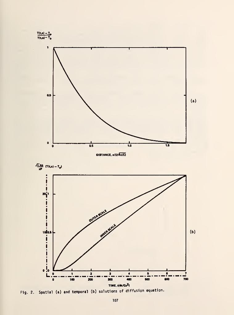
TM" To
(a)
^5 (TIWl-TJ
DISTANCE. K/uJkUc)
20
101 (b)
o
1 2 3 .4 .L. — ?-100 200 300 400 800 000
TIME. t(4k/Cx2)
Fig. 2. Spatial (a) and temporal (b) solutions of diffusion equation.
7
700
107

Our method of measurement is to record the temperatures, T, and T^ as a function oftime. This gives a pair of curves of the shape of Fig. 2b, but 'with different time scalessince Ti changes more rapidly after the power is turned on than L>, and of course L, isalways less than T
]. From these curves we can read off a pair of numbers T, and L, for a
particular time t'. For that particular time we then have both coordinates (T, , x?) and(T^.x^) for two points on the curve of Fig. 2a, which establishes the horizontal andvertical scales of that curve. This process involves use of the ratios x,/x
?and T,/T
?and
an interactive procedure (using a computer) which locates the two unique points having thecorrect values of these ratios. The ratio, k/C, is obtained directly from the horizontalscale factor and the product kC can be derived at x = from the vertical scale factor and
equation (2). The combination of this ratio and product yield the values of k and C.
It is only essential, of course, to measure T, and T?
at some convenient time t. How-ever, measuring T, and Tp as a function of time provides a high degree of redundancy whichis useful in checking for errors and inconsistencies in the method.
Since k and C are usually temperature dependent at low temperatures, it is important tochoose a power level and time scale such that T, and T~ do not rise ^ery much above theinitial value T . Otherwise, the temperature dependence of k and C must be consideredin equation (2), making the analysis difficult if not impossible. The use of small tempera-
ture intervals is standard practice in specific heat and thermal conductivity measurements.
Since the bar is not semi-infinite, the measurement time t' should be chosen small
enough that no appreciable amount of heat reaches the far end of the bar, otherwise the
spatial and temporal profiles given in Fig. 2 will no longer be accurate. Since the
spatial profile, Fig. 2a, approaches zero very quickly at large x, it seems satisfactory
to choose xo ( tne position at which Tp is measured) at about the middle of the real bar,
and then choose t1 such that the rise in Tp is no more than about 25% of the rise in T,
.
It is assumed that the position x, should Be near the free end of the bar. Any deviation
of the temporal profile from the curve of Fig. 2b might indicate that one or more of these
conditions has been violated.
6.0 r-
5.5 -
5.0 -
4.5
20 40 60 80 100 120
TIME (SECONDS)
Fig. 3. Temperature as a function of time for two thermometers on a G-10 epoxy fiberglassrod. The thermometers were 1.2 cm and 4 cm from the heater. The rod had a cross-
sectional area of 0.895 cm .
108

III. Results
Figure 3 shows the temperature at 2 thermometers on a G-10 epoxy-fiberglass rod as a .
function of time after a step function was applied to the heater. The rod area was .895 cm
and the thermometers were located 1.2 cm and 4.0 cm from the heater.
We found that the consistency of the results was poor if we selected a time t for
which the temperature change at the second thermometer was small. This is presumablyrelated to problems of resolution in the temperature at this point. We also found thatthe results varied considerably if the heat wave was allowed to reach the heat sink (the
temperature controlled end of the bar) before the temperature points were taken. Thisclearly relates to a breakdown in the assumption that the rod was semi -infinite.
For the data of Fig. 3, reasonable consistency in results was achieved over thetime interval of 40 to 75 seconds. While the temperature differences are a bit largerthan desired, we used the method described in the previous section to determine thethermal conductivity and specific heat of this material at 5 K., The thermal conductivitywas found to be 1.1 mW/cm-K and the specific heat was 4.7 mJ/cm -K.
These numbers fall within the range of values given by other investigators. Additionalwork must be done to arrive at a quantitative criterion for selection of valid data reqions.The measurement scheme is to be automated so as to provide for rapid acquisition of informa-tion over a modest temperature range for a variety of materials. One should note that thistechnique has been devised to deal with rapid evaluation of a wide range of materials. Anaccuracy of 10-20% should suffice for such a study and this method seems well suited to thetask.
IV. References
[1J. G. C. Danielson and P. H. Sidles, Thermal Diffusivity and Other Non-Steady-State
Methods, in Thermal Conductivity, edited by R. P. Type, 149-200 (Academic Press,
New York, NY, 1969).
109
NBS-114A (REV. 2-8C)
U.S. DEPT. OF COMM.
BIBLIOGRAPHIC DATASHEET (See instructions)
1. PUBLICATION ORREPORT NO.
NBS TN-1049
2. Performing Organ. Report No 3. Publication Date
January 1982
4. TITLE AND SUBTITLE
A Study of Design Principles for Refrigerators for Low-Power Cryoelectronic Devices
5. AUTHOR(S)
J. E. Zimmerman and D. B. Sullivan
6. PERFORMING ORGANIZATION (If joint or other than NBS, see instructions;
NATIONAL BUREAU OF STANDARDSDEPARTMENT OF COMMERCEWASHINGTON, D.C. 20234
7. Contract/Grant No.
8. Type of Report & Period Covered
9. SPONSORING ORGANIZATION NAME AND COMPLETE ADDRESS (Street, City, Stote, ZIP)
10. SUPPLEMENTARY NOTES
"2 Document describes a computer program; SF-185, FlPS Software Summary, is attached.
11. ABSTRACT (A 200-word or less factual summary of most significant information. If document includes a significantbibliography or literature survey, mention it here)
This report summarizes a five-year effort at NBS which has been directed
toward the development of low-power cryocoolers suited to the support of super-
conducting instruments. The report deals with a variety of aspects of construction
and operation of refrigerators as well as with a model which allows one to optimize
the design for minimum drive power. The publications generated by the program
are included as an appendix.
12. KEY WORDS (Six to twelve entries; alphabetical order; capitalize only proper names; and separate key words by semicolons)
Cryocooler; cryogenics; low temperature; refrigerator; Stirling cycle;
superconducting devices.
13. AVAILABILITY
fXf Unlimited
| |For Official Distribution. Do Not Release to NTIS
~\ Order From Superintendent of Documents, U.S. Government Printing Office, Washington, D.C.20402.
[~Xl Order From National Technical Information Service (NTIS), Springfield, VA. 22161
14. NO. OFPRINTED PAGES
114
15. Price
$11.00
•frU.S. GOVERNMENT PRINTING OFFICE:1982—577-445 ( 113USCOMM-DC 8043-PSO

NBS TECHNICAL PUBLICATIONS
PERIODICALS
JOURNAL OF RESEARCH—The Journal of Research of the
National Bureau of Standards reports NBS research and develop-
ment in those disciplines of the physical and engineering sciences in
which the Bureau is active. These include physics, chemistry,
engineering, mathematics, and computer sciences. Papers cover a
broad range of subjects, with major emphasis on measurementmethodology and the basic technology underlying standardization.
Also included from time to time are survey articles on topics
closely related to the Bureau's technical and scientific programs.
As a special service to subscribers each issue contains complete
citations to all recent Bureau publications in both NBS and non-
NBS media. Issued six times a year. Annual subscription: domestic
$16; foreign S20. Single copy, $3.75 domestic: $4.70 foreign.
NOTE: The Journal was formerly published in two sections: Sec-
tion A "Physics and Chemistry" and Section B "Mathematical
Sciences."
DIMENSIONS/NBS—This monthly magazine is published to in-
form scientists, engineers, business and industry leaders, teachers,
students, and consumers of the latest advances in science andtechnology, with primary emphasis on work at NBS. The magazine
highlights and reviews such issues as energy research, fire protec-
tion, building technology, metric conversion, pollution abatement,
health and safety, and consumer product performance. In addi-
tion, it reports the results of Bureau programs in measurementstandards and techniques, properties of matter and materials,
engineering standards and services, instrumentation, andautomatic data processing. Annual subscription: domestic $11;
foreign $13.75.
NONPERIODICALS
Monographs—Major contributions to the technical literature onvarious subjects related to the Bureau's scientific and technical ac-
tivities.
Handbooks—Recommended codes of engineering and industrial
practice (including safety codes) developed in cooperation with in-
terested industries, professional organizations, and regulatory
bodies.
Special Publications—Include proceedings of conferences spon-
sored by NBS, NBS annual reports, and other special publications
appropriate to this grouping such as wall charts, pocket cards, and
bibliographies.
Applied Mathematics Series— Mathematical tables, manuals, andstudies of special interest to physicists, engineers, chemists,
biologists, mathematicians, computer programmers, and others
engaged in scientific and technical work.
National Standard Reference Data Series— Provides quantitative
data on the physical and chemical properties of materials, com-piled from the world's literature and critically evaluated.
Developed under a worldwide program coordinated by NBS under
the authority of the National Standard Data Act (Public Law90-396).
NOTE: The principal publication outlet for the foregoing data is
the Journal of Physical and Chemical Reference Data (JPCRD)published quarterly for NBS by the American Chemical Society
(ACS) and the American Institute of Physics (AIP). Subscriptions,
reprints, and supplements available from ACS, 1 155 Sixteenth St.,
NW, Washington, DC 20056.
Building Science Series— Disseminates technical information
developed at the Bureau on building materials, components,systems, and whole structures. The series presents research results,
test methods, and performance criteria related to the structural andenvironmental functions and the durability and safety charac-
teristics of building elements and systems.
Technical Notes—Studies or reports which are complete in them-
selves but restrictive in their treatment of a subject. Analogous to
monographs but not so comprehensive in scope or definitive in
treatment of the subject area. Often serve as a vehicle for final
reports of work performed at NBS under the sponsorship of other
government agencies.
Voluntary Product Standards— Developed under procedures
published by the Department of Commerce in Part 10, Title 15, of
the Code of Federal Regulations. The standards establish
nationally recognized requirements for products, and provide all
concerned interests with a basis for common understanding of the
characteristics of the products. NBS administers this program as a
supplement to the activities of the private sector standardizing
organizations.
Consumer Information Series— Practical information, based on
NBS research and experience, covering areas of interest to the con-
sumer. Easily understandable language and illustrations provide
useful background knowledge for shopping in today's tech-
nological marketplace.
Order the above NBS publications from: Superintendent of Docu-
ments, Government Printing Office. Washington. DC 20402.
Order the following NBS publications—FIPS and NBSlR's—fromthe National Technical Information Services, Springfield. VA 22161
.
Federal information Processing Standards Publications (FIPS
PUB)— Publications in this series collectively constitute the
Federal Information Processing Standards Register. The Register
serves as the official source of information in the Federal Govern-
ment regarding standards issued by NBS pursuant to the Federal
Property and Administrative Services Act of 1949 as amended.
Public Law 89-306 (79 Stat. 1127), and as implemented by Ex-
ecutive Order 11717(38 FR 12315, dated May II, 1973) and Part 6
of Title 15 CFR (Code of Federal Regulations).
NBS Interagency Reports (NBSIR)—A special series of interim or
final reports on work performed by NBS for outside sponsors
(both government and non-government). In general, initial dis-
tribution is handled by the sponsor; public distribution is by the
National Technical Information Services, Springfield, VA 22161,
in paper copy or microfiche form.

U.S. DEPARTMENT OF COMMERCENational Bureau of StandardsWashington. D.C. 20234
OFFICIAL BUSINESS
Penalty for Private Use. $300
POSTAGE AND FEES PAIDU.S. DEPARTMENT OF COMMERCE
COM—215
SPECIAL FOURTH-CLASS RATEBOOK