A Statistical Analysis of Multipath Interference for impulse radio UWB systems
17
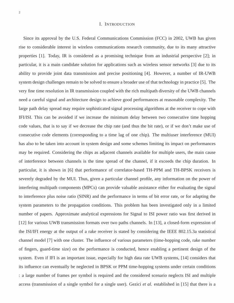
arXiv:1411.2345v1 [cs.NI] 10 Nov 2014 1 A Statistical Analysis of Multipath Interference for Impulse Radio UWB Systems Mihai I. Stanciu 5 , Stéphane Azou 1,3,∗ , Emanuel R˘ adoi 1,2 and Alexandru ¸ Serb˘ anescu 4 , Senior Member, IEEE 1 Université Européenne de Bretagne, France. 2 Université de Brest ; CNRS, UMR 6285 LabSTICC ; Brest, France 3 Ecole Nationale d’Ingénieurs de Brest; CNRS, UMR 6285 LabSTICC ; Brest, France 4 Military Technical Academy, Bucharest, Romania 5 Freescale Semiconductor, Bucharest, Romania * Corresponding author (E-mail : [email protected]) Abstract In this paper, we develop a statistical characterization of the multipath interference in an Impulse Radio (IR)- UWB system, considering the standardized IEEE 802.15.4a channel model. In such systems, the chip length has to be carefully tuned as all the propagation paths located beyond this limit can cause interframe/intersymbol interferences (IFI/ISI). Our approach aims at computing the probability density function (PDF) of the power of all multipath components with delays larger than the chip time, so as to prevent such interferences. Exact analytical expressions are derived first for the probability that the chip length falls into a particular cluster of the multipath propagation model and for the statistics of the number of paths spread over several contiguous clusters. A power delay profile (PDP) approximation is then used to evaluate the total interference power as the problem appears to be mathematically intractable. Using the proposed closed-form expressions, and assuming minimal prior information on the channel state, a rapid update of the chip time value is enabled so as to control the signal to interference plus noise ratio. Index Terms Impulse Radio, Time-Hopping, Chip duration, Multipath Interference, Statistical Analysis, IEEE 802.15.4a, Channel Model.
-
Upload
independent -
Category
Documents
-
view
11 -
download
0
Transcript of A Statistical Analysis of Multipath Interference for impulse radio UWB systems
arX
iv:1
411.
2345
v1 [
cs.N
I] 1
0 N
ov 2
014
1
A Statistical Analysis of Multipath Interference for
Impulse Radio UWB Systems
Mihai I. Stanciu5, Stéphane Azou1,3,∗, Emanuel Radoi 1,2 and Alexandru Serbanescu4,
Senior Member, IEEE
1Université Européenne de Bretagne, France.
2Université de Brest ; CNRS, UMR 6285 LabSTICC ; Brest, France
3Ecole Nationale d’Ingénieurs de Brest; CNRS, UMR 6285 LabSTICC ; Brest, France
4Military Technical Academy, Bucharest, Romania
5Freescale Semiconductor, Bucharest, Romania
∗Corresponding author (E-mail :[email protected])
Abstract
In this paper, we develop a statistical characterization ofthe multipath interference in an Impulse Radio (IR)-
UWB system, considering the standardized IEEE 802.15.4a channel model. In such systems, the chip length
has to be carefully tuned as all the propagation paths located beyond this limit can cause interframe/intersymbol
interferences (IFI/ISI). Our approach aims at computing the probability density function (PDF) of the power of all
multipath components with delays larger than the chip time,so as to prevent such interferences. Exact analytical
expressions are derived first for the probability that the chip length falls into a particular cluster of the multipath
propagation model and for the statistics of the number of paths spread over several contiguous clusters. A power
delay profile (PDP) approximation is then used to evaluate the total interference power as the problem appears to be
mathematically intractable. Using the proposed closed-form expressions, and assuming minimal prior information
on the channel state, a rapid update of the chip time value is enabled so as to control the signal to interference
plus noise ratio.
Index Terms
Impulse Radio, Time-Hopping, Chip duration, Multipath Interference, Statistical Analysis, IEEE 802.15.4a,
Channel Model.
2
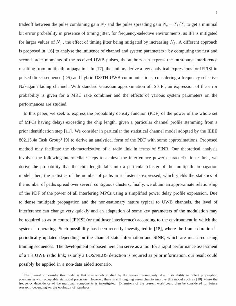
I. INTRODUCTION
Since its approval by the U.S. Federal Communications Commission (FCC) in 2002, UWB has given
rise to considerable interest in wireless communications research community, due to its many attractive
properties [1]. Today, IR is considered as a promising technique from an industrial perspective [2]; in
particular, it is a main candidate solution for applications such as wireless sensor networks [3] due to its
ability to provide joint data transmission and precise positioning [4]. However, a number of IR-UWB
system design challenges remain to be solved to ensure a broader use of that technology in practice [5]. The
very fine time resolution in IR transmission coupled with therich multipath diversity of the UWB channels
need a careful signal and architecture design to achieve good performances at reasonable complexity. The
large path delay spread may require sophisticated signal processing algorithms at the receiver to cope with
IFI/ISI. This can be avoided if we increase the minimum delaybetween two consecutive time hopping
code values, that is to say if we decrease the chip rate (and thus the bit rate), or if we don’t make use of
consecutive code elements (corresponding to a time lag of one chip). The multiuser interference (MUI)
has also to be taken into account in system design and some schemes limiting its impact on performances
may be required. Considering the chips as adjacent channelsavailable for multiple users, the main cause
of interference between channels is the time spread of the channel, if it exceeds the chip duration. In
particular, it is shown in [6] that performance of correlator-based TH-PPM and TH-BPSK receivers is
severely degraded by the MUI. Thus, given a particular channel profile, any information on the power of
interfering multipath components (MPCs) can provide valuable assistance either for evaluating the signal
to interference plus noise ratio (SINR) and the performancein terms of bit error rate, or for adapting the
system parameters to the propagation conditions. This problem has been investigated only in a limited
number of papers. Approximate analytical expressions for Signal to ISI power ratio was first derived in
[12] for various UWB transmission formats over two paths channels. In [13], a closed-form expression of
the ISI/IFI energy at the output of a rake receiver is stated by considering the IEEE 802.15.3a statistical
channel model [7] with one cluster. The influence of various parameters (time-hopping code, rake number
of fingers, guard-time size) on the performance is conducted, hence enabling a pertinent design of the
system. Even if IFI is an important issue, especially for high data rate UWB systems, [14] considers that
its influence can eventually be neglected in BPSK or PPM time-hopping systems under certain conditions
: a large number of frames per symbol is required and the considered scenario neglects ISI and multiple
access (transmission of a single symbol for a single user). Gezici et al. established in [15] that there is a
3
tradeoff between the pulse combining gainNf and the pulse spreading gainNc = Tf/Tc to get a minimal
bit errror probability in presence of timing jitter, for frequency-selective environments, as IFI is mitigated
for larger values ofNc , the effect of timing jitter being mitigated by increasingNf . A different approach
is proposed in [16] to analyse the influence of channel and system parameters : by computing the first and
second order moments of the received UWB pulses, the authorscan express the intra-burst interference
resulting from multipath propagation. In [17], the authorsderive a few analytical expressions for IFI/ISI in
pulsed direct sequence (DS) and hybrid DS/TH UWB communications, considering a frequency selective
Nakagami fading channel. With standard Gaussian approximation of ISI/IFI, an expression of the error
probability is given for a MRC rake combiner and the effects of various system parameters on the
performances are studied.
In this paper, we seek to express the probability density function (PDF) of the power of the whole set
of MPCs having delays exceeding the chip length, given a particular channel profile stemming from a
prior identification step [11]. We consider in particular the statistical channel model adopted by the IEEE
802.15.4a Task Group1 [9] to derive an analytical form of the PDF with some approximations. Proposed
method may facilitate the characterization of a radio link in terms of SINR. Our theoretical analysis
involves the following intermediate steps to achieve the interference power characterization : first, we
derive the probability that the chip length falls into a particular cluster of the multipath propagation
model; then, the statistics of the number of paths in a cluster is expressed, which yields the statistics of
the number of paths spread over several contiguous clusters; finally, we obtain an approximate relationship
of the PDF of the power of all interfering MPCs using a simplified power delay profile expression. Due
to dense multipath propagation and the non-stationary nature typical to UWB channels, the level of
interference can change very quickly andan adaptation of some key parameters of the modulation may
be required so as to control IFI/ISI (or multiuser interference) according to the environment in which the
system is operating. Such possibility has been recently investigated in [18], where the frame duration is
periodically updated depending on the channel state information and SINR, which are measured using
training sequences. The development proposed here can serve as a tool for a rapid performance assessment
of a TH UWB radio link; as only a LOS/NLOS detection is required as prior information, our result could
possibly be applied in a non-data aided scenario.
1The interest to consider this model is that it is widely studied by the research community, due to its ability to reflect propagationphenomena with acceptable statistical precision. However, there is still ongoing researches to improve this model such as [10] where thefrequency dependence of the multipath components is investigated. Extensions of the present work could then be considered for futureresearch, depending on the evolution of standards.
4
The paper is organized as follows. Section II briefly recallssome properties of the IEEE 802.15.4a
propagation channel and specifies the problem of statistical analysis of the interference power. Then, in
section III, we derive the statistics of the first cluster matching the chip length and the number of MPCs
is investigated in section IV. A power delay approximation then follows in section V and a procedure
for interference power estimation is developed in section VI. A few numerical results are then discussed
before some conclusions to confirm the pertinence of our theoretical analysis.
II. SYSTEM MODEL AND PROBLEM STATEMENT
We consider here a Time-Hopping Binary Pulse Amplitude Modulation (BPAM) format, with the
following typical expression of the transmitted signal :
stx(t) =
√
Es
Nf
∞∑
p=−∞
d⌊p/Nf⌋wtx (t− pTf − cpTc) , (1)
whereEs denotes the symbol energy andd⌊p/Nf⌋ ∈ −1, 1 are the binary transmitted symbols,Tf
stands for the average period of the pulse train (also known as the frame time), thecp ∈ 0, 1, ..., Nc−1
represent pseudo-random code elements required both for code division multiple access and spectral
shaping purposes, the quantification of temporal hops beingcontrolled by the chip lengthTc. The system
is designed so that the unit energy pulsewtx(t) is confined within durationTc and we haveTf = NcTc.
The indoor propagation channel usually involves multiple reflections due to the objects in the vicinity of
receiver and transmitter; a classical way to characterize such propagation conditions is to make use of the
Saleh-Valenzuela (SV) channel model [7] whose basic assumption is that MPCs arrive in clusters, with
complex variations of the received power due to path loss, large scale fading and small scale fading. The
corresponding discrete-time impulse response is usually expressed as
h(t) =
L∑
l=0
K∑
k=0
ak,lexp(jφk,l)δ(t−Tl−τk,l) (2)
whereak,l denotes the tap weight of thek-th component in thel-th cluster,τk,l is the delay of thek-th
MPC relative to thel-th cluster arrival timeTl and the phasesφk,l being uniformly distributed in the range
[0, 2π]; δ(t) is the Dirac delta function.
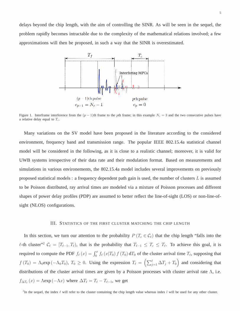
In case the maximum delay spread of the channel is larger thanthe chip time, the transmitted signal
corresponding to one pulse may overlap with signals in some next frames, as shown in Fig. 1, thus
causing IFI/ISI. Our objective is to derive a closed form expression of the power lying in time bins with
5
delays beyond the chip length, with the aim of controlling the SINR. As will be seen in the sequel, the
problem rapidly becomes intractable due to the complexity of the mathematical relations involved; a few
approximations will then be proposed, in such a way that the SINR is overestimated.
Figure 1. Interframe interference from the(p− 1)th frame to thepth frame; in this exampleNc = 3 and the two consecutive pulses havea relative delay equal toTc.
Many variations on the SV model have been proposed in the literature according to the considered
environment, frequency band and transmission range. The popular IEEE 802.15.4a statistical channel
model will be considered in the following, as it is close to a realistic channel; moreover, it is valid for
UWB systems irrespective of their data rate and their modulation format. Based on measurements and
simulations in various environements, the 802.15.4a modelincludes several improvements on previously
proposed statistical models : a frequency dependent path gain is used, the number of clustersL is assumed
to be Poisson distributed, ray arrival times are modeled viaa mixture of Poisson processes and different
shapes of power delay profiles (PDP) are assumed to better reflect the line-of-sight (LOS) or non-line-of-
sight (NLOS) configurations.
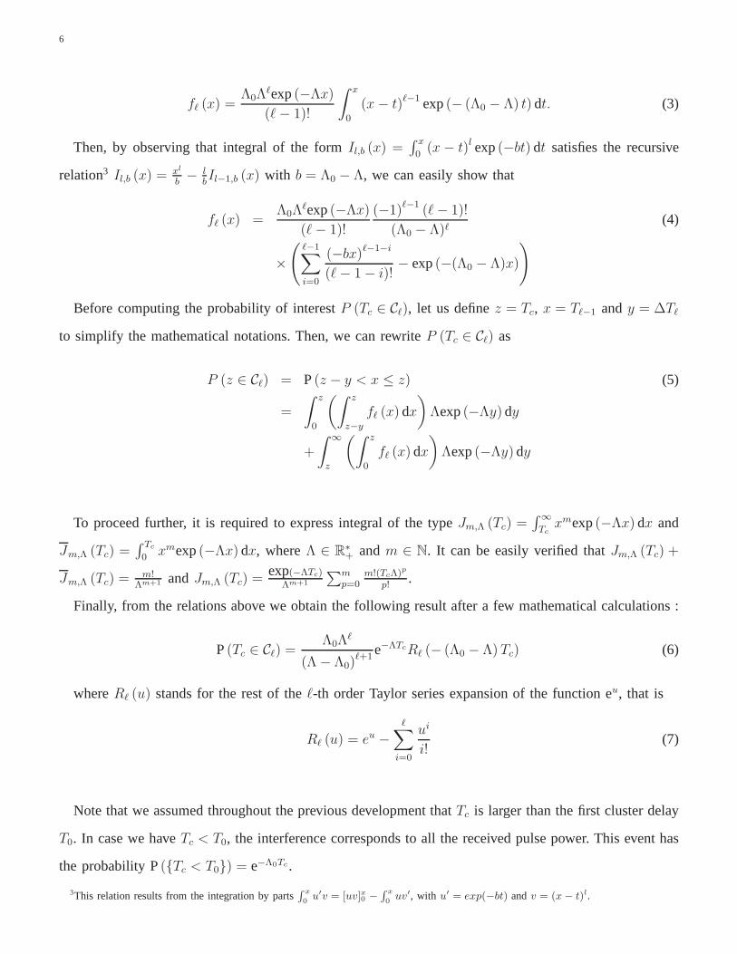
III. STATISTICS OF THE FIRST CLUSTER MATCHING THE CHIP LENGTH
In this section, we turn our attention to the probabilityP (Tc ∈ Cℓ) that the chip length “falls into the
ℓ-th cluster”2 Cℓ = [Tℓ−1, Tℓ), that is the probability thatTℓ−1 ≤ Tc ≤ Tℓ. To achieve this goal, it is
required to compute the PDFfℓ (x) =∫ x
0fℓ (x|T0) f (T0)dT0 of the cluster arrival timeTℓ, supposing that
f (T0) = Λ0exp(−Λ0T0), T0 ≥ 0. Using the expressionTℓ =(
∑ℓj=1∆Tj + T0
)
and considering that
distributions of the cluster arrival times are given by a Poisson processes with cluster arrival rateΛ, i.e.
f∆Tℓ(x) = Λexp(−Λx) where∆Tℓ = Tℓ − Tℓ−1, we get
2In the sequel, the indexℓ will refer to the cluster containing the chip length value whereas indexl will be used for any other cluster.
6
fℓ (x) =Λ0Λ
ℓexp(−Λx)
(ℓ− 1)!
∫ x
0
(x− t)ℓ−1 exp(− (Λ0 − Λ) t) dt. (3)
Then, by observing that integral of the formIl,b (x) =∫ x
0(x− t)l exp(−bt) dt satisfies the recursive
relation3 Il,b (x) =xl
b− l
bIl−1,b (x) with b = Λ0 − Λ, we can easily show that
fℓ (x) =Λ0Λ
ℓexp(−Λx)
(ℓ− 1)!
(−1)ℓ−1 (ℓ− 1)!
(Λ0 − Λ)ℓ(4)
×
(
ℓ−1∑
i=0
(−bx)ℓ−1−i
(ℓ− 1− i)!− exp(−(Λ0 − Λ)x)
)
Before computing the probability of interestP (Tc ∈ Cℓ), let us definez = Tc, x = Tℓ−1 andy = ∆Tℓ
to simplify the mathematical notations. Then, we can rewrite P (Tc ∈ Cℓ) as
P (z ∈ Cℓ) = P(z − y < x ≤ z) (5)
=
∫ z
0
(∫ z
z−y
fℓ (x) dx
)
Λexp(−Λy)dy
+
∫
∞
z
(∫ z
0
fℓ (x) dx
)
Λexp(−Λy)dy
To proceed further, it is required to express integral of thetype Jm,Λ (Tc) =∫
∞
Tcxmexp(−Λx) dx and
Jm,Λ (Tc) =∫ Tc
0xmexp(−Λx) dx, whereΛ ∈ R
∗
+ andm ∈ N. It can be easily verified thatJm,Λ (Tc) +
Jm,Λ (Tc) =m!
Λm+1 andJm,Λ (Tc) =exp(−ΛTc)
Λm+1
∑mp=0
m!(TcΛ)p
p!.
Finally, from the relations above we obtain the following result after a few mathematical calculations :
P(Tc ∈ Cℓ) =Λ0Λ
ℓ
(Λ− Λ0)ℓ+1
e−ΛTcRℓ (− (Λ0 − Λ) Tc) (6)
whereRℓ (u) stands for the rest of theℓ-th order Taylor series expansion of the function eu, that is
Rℓ (u) = eu −ℓ∑
i=0
ui
i!(7)
Note that we assumed throughout the previous development that Tc is larger than the first cluster delay
T0. In case we haveTc < T0, the interference corresponds to all the received pulse power. This event has
the probability P(Tc < T0) = e−Λ0Tc.
3This relation results from the integration by parts∫ x
0u′v = [uv]x0 −
∫ x
0uv′, with u′ = exp(−bt) andv = (x− t)l.

7
IV. ON THE NUMBER OF INTERFERINGMPCS
This section is devoted to the estimation of the number of MPCs that can cause interference, that is the
overall number of components located beyond the chip length. So, for any cluster indexl ∈ N , we need
to compute first the probabilityP (ni) for each subsequent clusterCi, l+1 ≤ i ≤ n, whereni denotes the
number of MPCs belonging to thei-th cluster. The distribution associated to the whole set ofinterfering
clusters will then be easily obtained in a second step.
In order to simplify our development, we will consider the approximation that there is no inter-cluster
interference; hence the delayτm,i of the m-th MPC relative to thei-th cluster arrival timeTi−1 belongs
to the interval[Ti−1, Ti). A second simplification is assumed for the ray arrival times; from [9] we know
that they can be modelled with mixtures of two Poisson processes with mixture probabilityβ and arrival
ratesλ1, λ2 being determined experimentally for various environments. As in the classical SV model,
we will adopt a Poisson process for the ray arrival times, so that the distribution of the delay difference
τl+1,i−τl,i of any two adjacent MPCs in clusterCi takes the formf(τl+1,i−τl,i) = λexp(−λ(τl+1,i−τl,i)),
where the value of the parameterλ is computed by minimizing the mean squared error between simplified
and original models, for a given radio environment (known values forβ, λ1, andλ2).
For any clusterCi, it can be shown (see Appendix) that the probabilityP (ni) that the number of MPCs
in the cluster isni, is
P(ni) =λniΛ
(λ+ Λ)ni+1 , ni ≥ 0 (8)
Then, we can characterize the number of MPCs within clustersCi; i = ℓ, ℓ+1, ..., L, whereL is the
total number of clusters and supposing thatTc ∈ Cℓ. This can be achieved by summingr+1 indepedent and
identically discrete random variables, each with probability (8), wherer = L−ℓ. The resulting probability
Pr (n) can be computed by recursion4, starting with P1 (n) =∑n
k=0 P0 (k)P0 (n− k) and P0 (n) being
expressed as in (8) :
Pr (n) =λn
(λ+ Λ)n
(
Λ
(λ+ Λ)
)r+1(n+ r)!
n!r!. (9)
4Note that this probability depends on the number(r + 1) of clusters beyondCℓ, with Tc ∈ Cℓ.
8
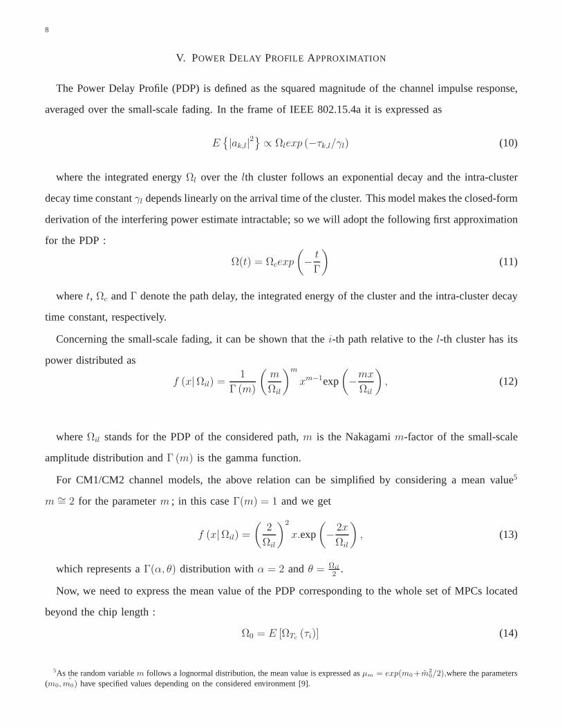
V. POWER DELAY PROFILE APPROXIMATION
The Power Delay Profile (PDP) is defined as the squared magnitude of the channel impulse response,
averaged over the small-scale fading. In the frame of IEEE 802.15.4a it is expressed as
E
|ak,l|2 ∝ Ωlexp (−τk,l/γl) (10)
where the integrated energyΩl over thelth cluster follows an exponential decay and the intra-cluster
decay time constantγl depends linearly on the arrival time of the cluster. This model makes the closed-form
derivation of the interfering power estimate intractable;so we will adopt the following first approximation
for the PDP :
Ω(t) = Ωcexp
(
−t
Γ
)
(11)
wheret, Ωc andΓ denote the path delay, the integrated energy of the cluster and the intra-cluster decay
time constant, respectively.
Concerning the small-scale fading, it can be shown that thei-th path relative to thel-th cluster has its
power distributed as
f (x|Ωil) =1
Γ (m)
(
m
Ωil
)m
xm−1exp
(
−mx
Ωil
)
, (12)
whereΩil stands for the PDP of the considered path,m is the Nakagamim-factor of the small-scale
amplitude distribution andΓ (m) is the gamma function.
For CM1/CM2 channel models, the above relation can be simplified by considering a mean value5
m ∼= 2 for the parameterm ; in this caseΓ(m) = 1 and we get
f (x|Ωil) =
(
2
Ωil
)2
x.exp
(
−2x
Ωil
)
, (13)
which represents aΓ(α, θ) distribution withα = 2 andθ = Ωil
2.
Now, we need to express the mean value of the PDP corresponding to the whole set of MPCs located
beyond the chip length :
Ω0 = E [ΩTc(τi)] (14)
5As the random variablem follows a lognormal distribution, the mean value is expressed asµm = exp(m0+m20/2),where the parameters
(m0, m0) have specified values depending on the considered environment [9].
9
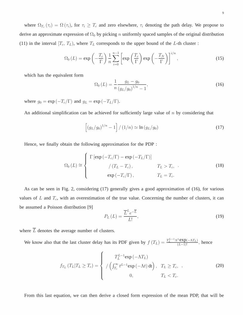
whereΩTc(τi) = Ω (τi), for τi ≥ Tc and zero elsewhere,τi denoting the path delay. We propose to
derive an approximate expression ofΩ0 by pickingn uniformly spaced samples of the original distribution
(11) in the interval[Tc, TL), whereTL corresponds to the upper bound of theL-th cluster :
Ω0 (L) = exp
(
−Tc
Γ
)
1
n
n−1∑
i=0
[
exp
(
Tc
Γ
)
exp
(
−TN
Γ
)]i/n
, (15)
which has the equivalent form
Ω0 (L) =1
n
gL − g0
(gL/g0)1/n − 1
, (16)
whereg0 = exp(−Tc/Γ) andgL = exp(−TL/Γ).
An additional simplification can be achieved for sufficiently large value ofn by considering that
[
(gL/g0)1/n − 1
]
/ (1/n) ≃ ln (gL/g0) (17)
Hence, we finally obtain the following approximation for thePDP :
Ω0 (L) ∼=
Γ [exp(−Tc/Γ)− exp(−TL/Γ)]
/ (TL − Tc) , TL > Tc,
exp(−Tc/Γ) , TL = Tc.
. (18)
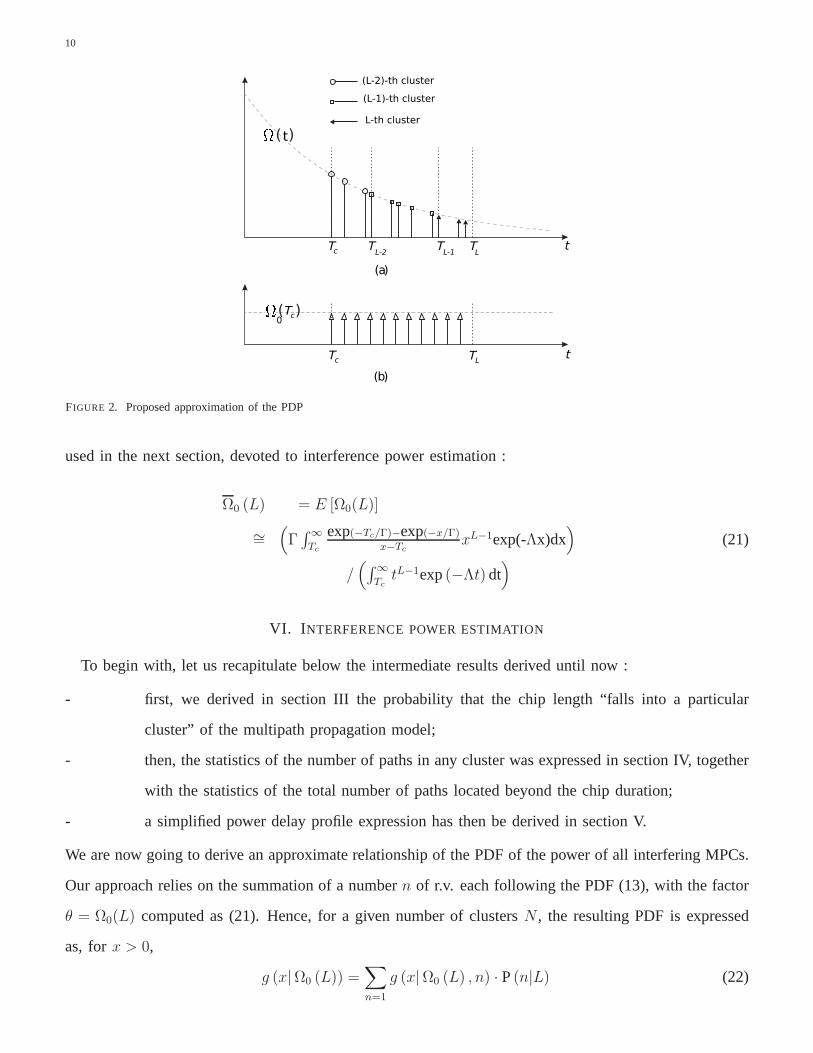
As can be seen in Fig. 2, considering (17) generally gives a good approximation of (16), for various
values ofL andTc, with an overestimation of the true value. Concerning the number of clusters, it can
be assumed a Poisson distribution [9]
PL (L) =L
Le−L
L!, (19)
whereL denotes the average number of clusters.
We know also that the last cluster delay has its PDF given byf (TL) =TL−1
LΛLexp(−ΛTL)
(L−1)!, hence
fTL(TL|TL ≥ Tc) =
TL−1L exp(−ΛTL)
/(
∫
∞
TctL−1exp(−Λt) dt
)
, TL ≥ Tc,
0, TL < Tc.
, (20)
From this last equation, we can then derive a closed form expression of the mean PDP, that will be
10
tT T T T
(t)
tTc TL
( )0Tc
(a)
(b)
LL-1L-2c
(L-2)-th cluster
(L-1)-th cluster
L-th cluster
FIGURE 2. Proposed approximation of the PDP
used in the next section, devoted to interference power estimation :
Ω0 (L) = E [Ω0(L)]
∼=(
Γ∫
∞
Tc
exp(−Tc/Γ)−exp(−x/Γ)
x−TcxL−1exp(-Λx)dx
)
(21)
/(
∫
∞
TctL−1exp(−Λt) dt
)
VI. I NTERFERENCE POWER ESTIMATION
To begin with, let us recapitulate below the intermediate results derived until now :
- first, we derived in section III the probability that the chip length “falls into a particular
cluster” of the multipath propagation model;
- then, the statistics of the number of paths in any cluster was expressed in section IV, together
with the statistics of the total number of paths located beyond the chip duration;
- a simplified power delay profile expression has then be derived in section V.
We are now going to derive an approximate relationship of thePDF of the power of all interfering MPCs.
Our approach relies on the summation of a numbern of r.v. each following the PDF (13), with the factor
θ = Ω0(L) computed as (21). Hence, for a given number of clustersN , the resulting PDF is expressed
as, forx > 0,
g (x|Ω0 (L)) =∑
n=1
g (x|Ω0 (L) , n) · P(n|L) (22)
11
where
g (x|Ω0 (L) , n) =
(
2
Ω0 (L)
)2nx2n−1
(2n− 1)!· exp
(
−2x
Ω0 (L)
)
(23)
and the number of paths with delays exceedingTc being determined as (under the assumption that each
cluster contains at least one path)
P(n|L) =L−1∑
k=0
P(n|k, L) · P(k) , (24)
The above expression can be computed by taking advantage of previous developments ; for example,
in case of a LOS environment (and considering thatT0 = 0), we get
P(n|k, L) =(
λλ+Λ
)n−L+k(
Λ(λ+Λ)
)L−k
× (n−1)!(n−L+k)!(L−k−1)!
, ∀n ≥ 1(25)
and
P(k) =(ΛTc)
k exp(−ΛTc)
k!. (26)
To complete our analysis, we need also to consider the casex = 0, which results in a discrete part of the
PDF :
g (x = 0|Ω0 (L)) = P(n = 0|L) (27)
=
∞∑
k=L
P(k)
And finally, the interference power is obtained as
g (x) =∞∑
L=1
g (x|Ω0 (L))PL (L) . (28)
No compact analytical expression of this PDF can be obtaineddue to the high complexity of the terms
involved ; however, we can observe that the proposed result can easily be implemented to get an estimate at
very limited computational cost. Note also that our development remains valid for both LOS and NLOS
environments ; in the latter case, the probability that the chip length falls into thekth cluster has the
alternative expression
P(k) =(ΛTc)
k+1 exp(−ΛTc)
(k + 1)!. (29)
12
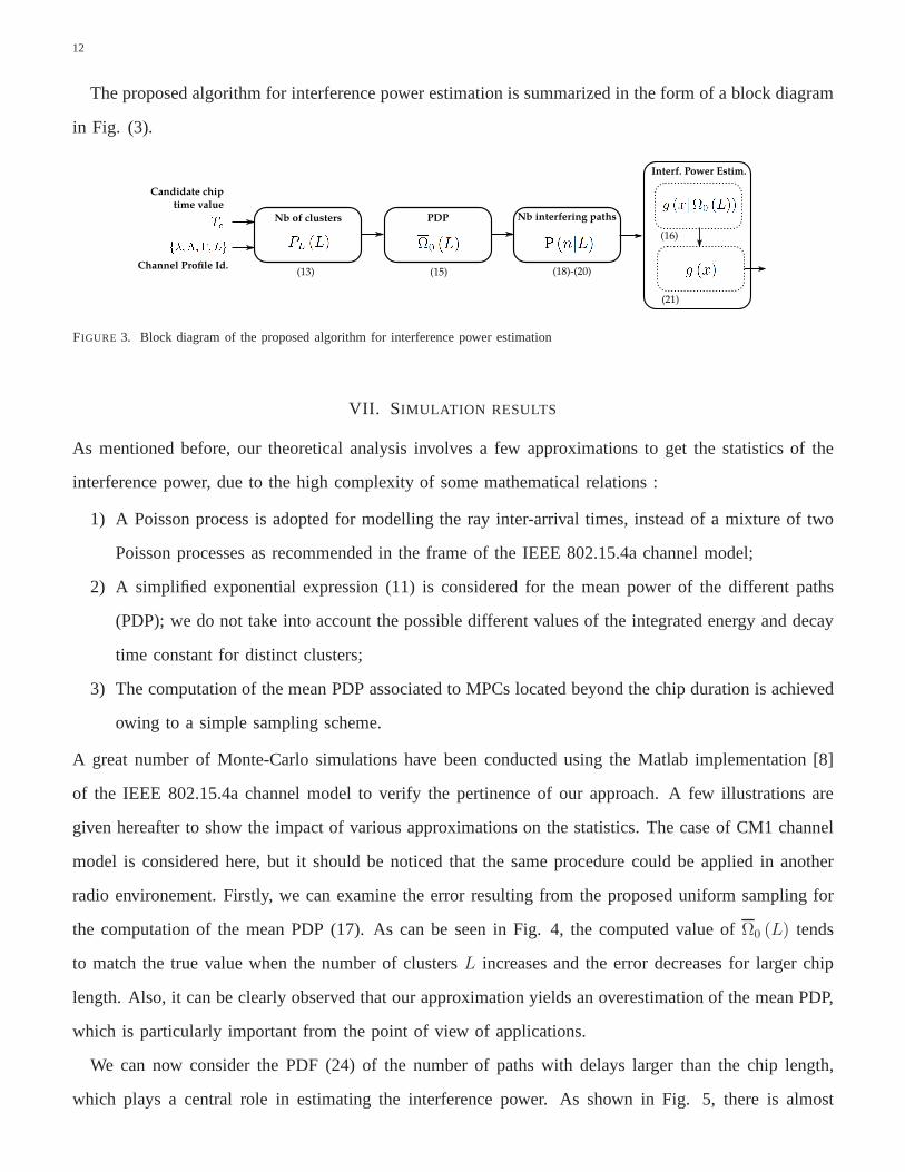
The proposed algorithm for interference power estimation is summarized in the form of a block diagram
in Fig. (3).
Nb of clusters PDP Nb interfering paths
Interf. Power Estim.
Candidate chip
time value
Channel Profile Id.(13) (15) (18)-(20)
(16)
(21)
FIGURE 3. Block diagram of the proposed algorithm for interferencepower estimation
VII. SIMULATION RESULTS
As mentioned before, our theoretical analysis involves a few approximations to get the statistics of the
interference power, due to the high complexity of some mathematical relations :
1) A Poisson process is adopted for modelling the ray inter-arrival times, instead of a mixture of two
Poisson processes as recommended in the frame of the IEEE 802.15.4a channel model;
2) A simplified exponential expression (11) is considered for the mean power of the different paths
(PDP); we do not take into account the possible different values of the integrated energy and decay
time constant for distinct clusters;
3) The computation of the mean PDP associated to MPCs locatedbeyond the chip duration is achieved
owing to a simple sampling scheme.
A great number of Monte-Carlo simulations have been conducted using the Matlab implementation [8]
of the IEEE 802.15.4a channel model to verify the pertinenceof our approach. A few illustrations are
given hereafter to show the impact of various approximations on the statistics. The case of CM1 channel
model is considered here, but it should be noticed that the same procedure could be applied in another
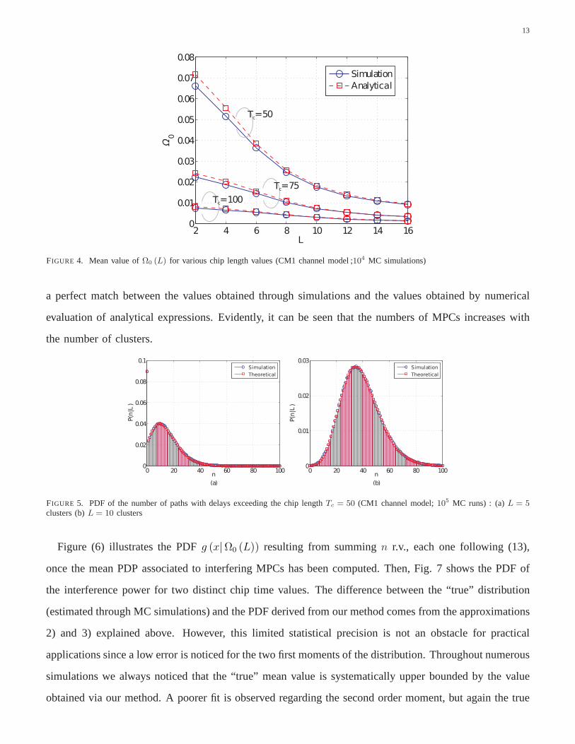
radio environement. Firstly, we can examine the error resulting from the proposed uniform sampling for
the computation of the mean PDP (17). As can be seen in Fig. 4, the computed value ofΩ0 (L) tends
to match the true value when the number of clustersL increases and the error decreases for larger chip
length. Also, it can be clearly observed that our approximation yields an overestimation of the mean PDP,
which is particularly important from the point of view of applications.
We can now consider the PDF (24) of the number of paths with delays larger than the chip length,
which plays a central role in estimating the interference power. As shown in Fig. 5, there is almost
13
2 4 6 8 10 12 14 160
0.01
0.02
0.03
0.04
0.05
0.06
0.07
0.08
L
Ω0
Simulation
Analytical
Tc=50
Tc=75
Tc=100
FIGURE 4. Mean value ofΩ0 (L) for various chip length values (CM1 channel model ;104 MC simulations)
a perfect match between the values obtained through simulations and the values obtained by numerical
evaluation of analytical expressions. Evidently, it can beseen that the numbers of MPCs increases with
the number of clusters.
0 20 40 60 80 1000
0.01
0.02
0.03
n
Simulation
Theoretical
0 20 40 60 80 1000
0.02
0.04
0.06
0.08
0.1
n
P(
|)
n L
Simulation
Theoretical
(a) (b)
P(
|)
n L
FIGURE 5. PDF of the number of paths with delays exceeding the chip length Tc = 50 (CM1 channel model;105 MC runs) : (a)L = 5clusters (b)L = 10 clusters
Figure (6) illustrates the PDFg (x|Ω0 (L)) resulting from summingn r.v., each one following (13),
once the mean PDP associated to interfering MPCs has been computed. Then, Fig. 7 shows the PDF of
the interference power for two distinct chip time values. The difference between the “true” distribution
(estimated through MC simulations) and the PDF derived fromour method comes from the approximations
2) and 3) explained above. However, this limited statistical precision is not an obstacle for practical
applications since a low error is noticed for the two first moments of the distribution. Throughout numerous
simulations we always noticed that the “true” mean value is systematically upper bounded by the value
obtained via our method. A poorer fit is observed regarding the second order moment, but again the true

14
variance is upper bounded by the computed value forg(x).
0 1 2 3 40
0.1
0.2
0.3
0.4
0.5
0.6
0.7
0 1 2 3 40
0.5
1
1.5
x
gx(|Ω
0())
L
x
Analytical - Continuous part
Simulations - Continuous part
Analytical - Discrete part
Simulations - Discret part
Analytical - Continuous part
Simulations - Continuous part
Analytical - Discrete part
Simulations - Discret part
gx(|Ω
0())
L
(a) (b)
FIGURE 6. PDFg (x|Ω0 (L))for CM1 channel model,Tc = 50 : (a) L = 2 clusters (b)L = 4 clusters
0 1 2 3 4 50
0.1
0.2
0.3
0.4
0.5
0.6
0.7
0.8
0.9
1
0 2 4 6 8 100
0.05
0.1
0.15
0.2
0.25
0.3
0.35
0.4
0.45
0.5
x
gx()
(a)x(b)
gx()
Analytical - Continuous part
Simulations - Continuous part
Analytical - Discrete part
Simulations - Discret part
Analytical - Continuous part
Simulations - Continuous part
Analytical - Discrete part
Simulations - Discret part
FIGURE 7. PDF of the interference powerg(x) for CM1 channel model (105MC runs) : (a)Tc = 25 (b) Tc = 50
Additional simulations have been conducted in NLOS radio environments to evaluate the pertinence of
the proposed algorithm. For CM2/CM4 channels (NLOS residential/office), we obtained the PDFs depicted
in Fig. 8 & 9, for the same candidate values of the chip time. The results appear to be acceptable, with
a good precision regarding the first two moments.
VIII. C ONCLUSIONS
A novel approach for the statistical characterization of the multipath interference in IR-UWB systems
has been developed in this paper. In the frame of the IEEE 802.15.4a channel model, we derived a
theoretical analysis which aims to compute the power corresponding to all multipath components located
beyond the chip length. Since the proposed approach requires minimal knowledge on the channel state, it
can be helpful for real time adaptation of modulation parameters so as to limit the signal to interference
plus noise ratio. Our method relies on the following key developments : first, we derived the probability

15
0 2 4 6 8 100
0.05
0.1
0.15
0.2
0.25
0.3
0.35
0.4
g(x)
x(a)
Analytical − Continuous partSimulations − Continuous partAnalytical − Discrete partSimulations − Continuous part
0 0.5 1 1.5 2 2.5 3 3.5 4 4.5 50
0.1
0.2
0.3
0.4
0.5
0.6
0.7
0.8
g(x)
x(b)
Analytical − Continuous partSimulations − Continuous partAnalytical − Discrete partSimulations − Continuous part
FIGURE 8. PDF of the interference powerg(x) for CM2 channel model (105MC runs) : (a)Tc = 25 (b) Tc = 50
0 5 10 15 200
0.1
0.2
0.3
0.4
0.5
0.6
0.7
g(x)
x(a)
Analytical − Continuous partSimulations − Continuous partAnalytical − Discrete partSimulations − Continuous part
0 2 4 6 8 100
0.2
0.4
0.6
0.8
1
g(x)
x(b)
Analytical − Continuous partSimulations − Continuous partAnalytical − Discrete partSimulations − Continuous part
FIGURE 9. PDF of the interference powerg(x) for CM4 channel model (105MC runs) : (a)Tc = 25 (b) Tc = 50
that the chip length falls into a particular cluster of the multipath propagation model; then, the statistics
of the number of paths spread over several contiguous clusters have been computed in closed-form;
finally, we obtained an approximate relationship of the PDF of the power of all interfering MPCs using
a simplified power delay profile expression. Numerous Monte-Carlo simulations have been carried out to
verify the pertinence of our results; although these simulations revealed a significant gap between the true
interference power distribution and that obtained throughour approach, the first two computed moments
are very close and upper-bound the true ones. This is a very useful result because they represent an
information that helps us to control the SINR level and to ensure an effective functioning of the IR-UWB
system in real-world scenarios. An experimental validation of these theoretical results is also planned
for the near future using an UWB platform recently acquired by our research team. Although some
measured data acquired with this platform is already available, it could not be used in the framework
of this paper because the conditions required for accurately matching the IEEE 802.15.4a environment
have not yet been met. An already scheduled upgrade of our experimental UWB platform will lead to
16
increased performance, especially in terms of bandwidth, and will enable an appropriate and meaningful
comparison of the theoretical results presented in this paper to those that will be obtained from measured
data.
APPENDIX
Appendix A - Proof of (8)
For any clusterCi, let us define the following notations:x = τni,i−τ0,i, y = τ(ni+1),i−τni,i andz = ∆Ti.
The probability that the number of MPCs in the cluster isni can then be written as
P(ni) =
∫
∞
0
P (ni|z) f (z) dz (30)
wheref(z) = Λexp(−Λz) is the PDF of the cluster arrival times and with the conditional probability
P(ni|z) = P(z − y < x ≤ z) (31)
=
∫ z
0
(∫ z
z−y
f(x)dx
)
λexp(−λy)dy
+
∫
∞
z
(∫ z
0
f(x)dx
)
λexp(−λy)dy
Considering the simplified model of the ray arrival times, itcan be easily seen that
f(x) =xni−1
(ni − 1)!λniexp(−λx) (32)
Therefore we get, after a few algebra steps,
P(ni|z) =(λz)ni
ni!exp(−λz) (33)
which finally yields (8).
REFERENCES
[1] H. Arslan, Z. N. Chen, M.-G. Di Benedetto, “Ultra Wideband Wireless Communication,” Wiley-Interscience, Oct. 2006.
[2] A. Willig, “Recent and Emerging Topics in Wireless Industrial Communications: A Selection,”IEEE Trans. Industrial Informatics,
4(2): 102-124, 2008.
[3] J. Zhang, P. V. Orlik, Z. Sahinoglu, A. F. Molisch, and P. Kinney, “UWB systems for wireless sensor networks,”Proceedings of the
IEEE, vol. 97, no. 2, pp. 313–331, 2009.
17
[4] S. Gezici, Z. Tian, G. B. Giannakis, et al., “Localization via ultra-wideband radios: a look at positioning aspects of future sensor
networks,” IEEE Signal Processing Magazine, vol. 22, no. 4, pp. 70–84, 2005.
[5] L. Lampe, K. Witrisal, “Challenges and recent advances in IR-UWB system design,”inProc. IEEE ISCAS, pp. 3288-3291, 2010.
[6] B. Hu, N. C. Beaulieu, “Accurate evaluation of multiple access performance in TH-PPM and TH-BPSK UWB systems,”IEEE Trans.
on Communications, pp. 1758-1766, 2004.
[7] A. Molisch, “Ultra-Wide-Band Propagation Channels,”Proceedings of the IEEE, Vol. 97, No. 2, pp. 353-371, 2009.
[8] A. F. Molisch et al., “IEEE 802.15.4a channel model - finalreport,” IEEE 802.15 WPAN Low Rate Alternative PHY Task Group 4a
(TG4a), Tech. Rep., Nov. 2004.
[9] A. Molisch, D. Cassioli, C. C. Chong, S. Emami, A. Fort, B.Kannan, J. Kåredal, J. Kunisch, H. G. Schantz, K. Siwiak, M. Z. Win,
”A comprehensive standardized model for ultrawideband propagation channels,”IEEE Trans. on Antennas and Propagation, Vol. 54,
No. 11, pp. 3151-3166, 2006.
[10] K. Haneda, A. Richter, A.F. Molisch, “Modeling the Frequency Dependence of Ultra-Wideband Spatio-Temporal Indoor Radio
Channels”,IEEE Trans. Antennas and Propagation, Vol. 60, No. 6, june 2012.
[11] S. Venkatesh and R.M. Buehrer, “Non-line-of-sight identification in ultra-wideband systems based on received signal statistics”,IET
Microw. Antennas Propag., 1, (6), pp. 1120 –1130, 2007.
[12] L. Piazzo, F. Ameli, “On the Inter-Symbol-Interference in several Ultra Wideband systems” inProc. IEEE Int. Symp. on Wireless
Communication Systems (ISWCS’05), pp. 259 – 262, Sept. 2005.
[13] A. L. Deleuze, P. Ciblat, C.J. Martret, “Inter-symbol/Inter-Frame Interference in Time-Hopping Ultra Wideband Impulse Radio System,”
in Proc. IEEE Int. Conf. on Ultra-Wideband, pp. 396-401, 2005.
[14] S. Ahmed, H. Arslan, “Inter-Frame Interference in TimeHopping Impulse Radio Based UWB Systems for Coherent Receivers,” in
Proc. IEEE Vehicular Technology Conf., pp. 1-6, 2006.
[15] S. Gezici, A. F. Molisch, H. V. Poor, and H. Kobayashi, “The Trade-off Between Processing Gains of an Impulse Radio UWB System
in the Presence of Timing Jitter”,IEEE Trans. Comm., 55, 1504-1515 (2007).
[16] K. Witrisal, “Statistical Analysis of the IEEE 802.15.4a UWB PHY over Multipath Channels,” inProc. IEEE WCNC Conference, pp.
130-135, 2008.
[17] M. A. Rahman, S. Sasaki, S. T. Islam, T. Baykas, C.-S. Sum, J. Wang, R. Funada, H. Harada, S. Kato, “Analysis and Comparison
of Inter-Symbol/Frame Interference in Pulsed DS- and Hybrid DS/TH-UWB Communications,”inProc. IEEE Vehicular Technology
Conf., 2009.
[18] A. F. Molisch, “Adaptive Frame Durations for Time-Hopped Impulse Radio Systems,” Patent US 7,620,369 B2, 7 Nov. 2009.
[19] A. Papoulis, S. U. Pillai, “Probability, Random Variables, and Stochastic Processes,” McGraw-Hill Publishing Co., 4th Edition, Jan.
2002.