A Solution to the Inherent List on Nimitz Class Aircraft Carriers
159
A Solution to the Inherent List on Nimitz Class Aircraft Carriers by Dianna Wolfson B.S. Marine Engineering Systems, United States Merchant Marine Academy, 1996 Submitted to the Departments of Ocean Engineering and Civil and Environmental Engineering in Partial Fulfillment of the Requirements for the Degrees of Naval Engineer and Master of Science in Civil and Environmental Engineering at the Massachusetts Institute of Technology June 2004 Author © 2004 Dianna Wolfson All rights reserved The author hereby grants MIT and the U.S. Government permission to reproduce and to distribute publicly paper and electronic copies of this thesis document in whole or in part. Department of Ocean Engineering and the Department of Civil and Environmental Engineering May 07, 2004 Certified by Certified by Accepted by Accepted by David V. Burke, Senior Lecturer Department of Ocean Engineering Thesis Supervisor Eduardo Kausel, Professor of Civil and Environmental Engineering Department of Civil and Environmental Engineering Thesis Reader Heidi Nepf, ssociate Professor of Civil and Environmental Engineering Chairman, Departmental Committee on Graduate Studies Department of Civil and Environmental Engineering Michael S. Triantafyllou, Professor of Ocean Engineering Chairman, Departmental Committee on Graduate Studies Department of Ocean Engineering BEST AVAILABLE COPY DISTRIBUTION STATEMENT A Approved for Public Release Distribution Unlimited 20040901 104
-
Upload
khangminh22 -
Category
Documents
-
view
1 -
download
0
Transcript of A Solution to the Inherent List on Nimitz Class Aircraft Carriers
A Solution to the Inherent List on Nimitz Class Aircraft Carriers
by
Dianna Wolf son
B.S. Marine Engineering Systems, United States Merchant Marine Academy, 1996
Submitted to the Departments of Ocean Engineering and Civil and Environmental Engineering in Partial Fulfillment of the Requirements for the Degrees of
Naval Engineer and
Master of Science in Civil and Environmental Engineering
at the Massachusetts Institute of Technology
June 2004
Author
© 2004 Dianna Wolfson All rights reserved
The author hereby grants MIT and the U.S. Government permission to reproduce and to distribute publicly paper and electronic copies of this thesis document in whole or in part.
Department of Ocean Engineering and the Department of Civil and Environmental Engineering
May 07, 2004
Certified by
Certified by
Accepted by
Accepted by
David V. Burke, Senior Lecturer Department of Ocean Engineering
Thesis Supervisor
Eduardo Kausel, Professor of Civil and Environmental Engineering Department of Civil and Environmental Engineering
Thesis Reader
Heidi Nepf, ssociate Professor of Civil and Environmental Engineering Chairman, Departmental Committee on Graduate Studies
Department of Civil and Environmental Engineering
Michael S. Triantafyllou, Professor of Ocean Engineering Chairman, Departmental Committee on Graduate Studies
Department of Ocean Engineering
BEST AVAILABLE COPY
DISTRIBUTION STATEMENT A Approved for Public Release
Distribution Unlimited
20040901 104

PAGE INTENTIONALLY LEFT BLANK
A Solution to the Inherent List on Nimitz Class Aircraft Carriers
by
Dianna Wolfson
Submitted to the Departments of Ocean Engineering and Civil and Environmental Engineering
on May 07, 2004, in partial fulfillment of the Requirements for the degrees of
Naval Engineer and
Master of Science in Civil and Environmental Engineering
Abstract
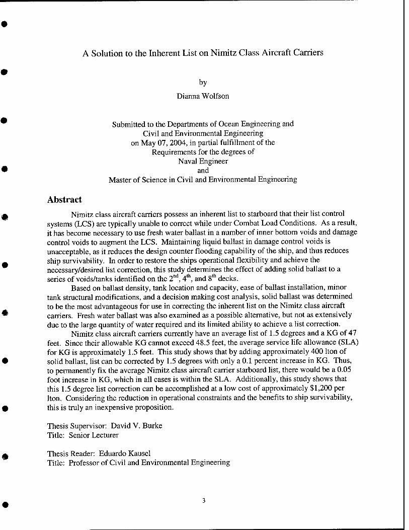
Nimitz class aircraft carriers possess an inherent list to starboard that their list control systems (LCS) are typically unable to correct while under Combat Load Conditions. As a result, it has become necessary to use fresh water ballast in a number of inner bottom voids and damage control voids to augment the LCS. Maintaining liquid ballast in damage control voids is unacceptable, as it reduces the design counter flooding capability of the ship, and thus reduces ship survivability. In order to restore the ships operational flexibility and achieve the necessary/desired list correction, this study determines the effect of adding solid ballast to a series of voids/tanks identified on the 2""^, 4*, and 8* decks.
Based on ballast density, tank location and capacity, ease of ballast installation, minor tank structural modifications, and a decision making cost analysis, solid ballast was determined to be the most advantageous for use in correcting the inherent list on the Nimitz class aircraft carriers. Fresh water ballast was also examined as a possible alternative, but not as extensively due to the large quantity of water required and its limited ability to achieve a list correction.
Nimitz class aircraft carriers currently have an average list of L5 degrees and a KG of 47 feet. Since their allowable KG cannot exceed 48.5 feet, the average service life allowance (SLA) for KG is approximately 1.5 feet. This study shows that by adding approximately 400 Iton of solid ballast, list can be corrected by 1.5 degrees with only a 0.1 percent increase in KG. Thus, to permanently fix the average Nimitz class aircraft carrier starboard list, there would be a 0.05 foot increase in KG, which in all cases is within the SLA. Additionally, this study shows that this L5 degree list correction can be accomplished at a low cost of approximately $1,200 per Iton. Considering the reduction in operational constraints and the benefits to ship survivability, this is truly an inexpensive proposition.
Thesis Supervisor: David V. Burke Title: Senior Lecturer
Thesis Reader: Eduardo Kausel Title: Professor of Civil and Environmental Engineering
Acknowledgements
I would like to thank CDR Kevin Terry who contacted MIT with a project proposal to find an advantageous and cost effective solution for fixing the inherent list on the Nimitz class aircraft carriers. Without his support, this thesis would not have been possible.
Throughout the course of this project, many individuals from various organizations provided invaluable operational and technical assistance. I would like to take this opportunity to thank everyone for their contributions and advice. I would also like to thank my husband for his friendship, love, and encouragement over the past three years and always.
NAVSEA CDR Kevin Terry CAPT (ret.) Chuck Bush CAPT T. Moore CAPT James Murdoch Dominick Cimino Roger M. Nutting Evelisse Marti r Wei don Gimbel LCDR Brian Lawerence LCDR Rick Thiel
Bath Iron Works John Grostick Lew Pratt Allen Pac Ray Lacour LCDR Michael Taylor
CVN Ships LCDR Chariie Strassle (DCA, CVN 69) CDR Robert Finely (Cheng, CVN 71) LCDR Peter Pasquale (DCA, CVN 71) LCDR John Rickards (DCA, CVN 72) LCDR Scott Noe (DCA, CVN 76) CDR Glenn Hofert (Cheng, CVN 76)
Massachusetts Institute of Technology Dr. David V. Burke CDR (ret.) John Amy CDR Timothy McCoy
NGC - Newport News Shipbuilding Jerry Dudley Hal McCaskill
NSWC Carderock John M. Rosborough Carlos R. Corretjer Charlie Snelling Bruce Winterstein Todd Heidenreich
PCCI. Inc. John A. 'Tony" Kupersmith Jessica R. Coles
Herbert Engineering Corporation Colin Moore
Norfolk Naval Shipvard Walt Delong Larry Back
Ballast Technologies. Inc. Mark Ensio
N.S. NAPPI Associates Nat Nappi, Sr.
#
Please accept my apologies if I have left someone off this list.
Table of Contents
Abstract 3 Acknowledgements 4 Table of Contents 5 List of Figures 6 List of Tables 6 List of Appendices 6 1.0 Introduction 7 1.0 Introduction 7
1.1 Motivation 7 1.2 Background 7
1.2.1 Past Research 10 1.2.2 Stability 10 1.2.3 Survivability 13 1.2.4 Displacement Limits 14 1.2.5 KG Limits 14
1.3 Present Options 15 1.3.1 Continue to operate using inner bottom and DC voids 15 1.3.2 Add a list control tank on the port side 17 1.3.3 Move or exchange compartment spaces 18 1.3.4 Convert a current DC void(s) to a JP-5 tank(s) and pump last 18 1.3.5 Future ship alterations and modifications 18 1.3.6 Re-examine current List Control System 19 1.3.7 Ballast Addition 21
1.3.7.1 Water Ballast 21 1.3.7.2 Solid Ballast 21
1.4 Option Selection 23 2.0 Preliminary Analysis and Results 23
2.1 Tank Selection 24 2.2 Modeling Analysis Performed 25 2.3 Preliminary Decision-Making Cost Estimation 31 2.4 Structural Analysis 35
2.4.1 Structural Modifications 39 2.4.1.1 Modifications to the 2"'* Deck 39 2.4.1.2 Modifications to the 4"" Deck 41 2.4.1.3 Modifications to the 8* Deck 43
3.0 Final Analysis and Results 44 3.1 Final POSSE Results 45 3.2 Final Cost Estimation 46
3.2.1 Ease of Removal 48 3.2.2 Evidence Perma Ballast® is non-corrosive 48
4.0 Conclusion 50 5.0 Recommendations 51
References 53
List of Figures
Figure 1: Stresses in rectangular plates under uniform lateral pressure [2] 38 Figure 2: 2"^* Deck Compartment 2-165-8-V 39 Figure 3: 2"'' Deck Compartment 2-165-8-V, transverse section 41 Figure 4: 4"" Deck Compartment 4-165-4-V 42 Figure 5: S'*" Deck Compartment 8-225-6-V 43
List of Tables
Table 1: CVN 68 Class Delivery Data and Class Predictions as of 11/17/03 8 Table 2: Deck Location Cost Comparison 32 Table 3: Required Structural Modifications for 2-165-8-V 40 Table 4: Required Structural Modifications for 4-165-4-V 42 Table 5: Required Structural Modifications for 8-225-6-V 44 Table 6: Final Cost, Weight Addition, and Change in KG Comparison 47
List of Appendices
Appendix A: Tank Location Study 54 Appendix B: Preliminary POSSE Modeling Results 58 Appendix C: Preliminary Cost Estimation Data and Worksheets 62 Appendix D: Preliminary Cost Comparison 86 Appendix E: Complete Structural Analysis 88 Appendix F: Final POSSE Modeling Results 148 Appendix G: Final Cost Estimation Data and Worksheets 150
1.0 Introduction
1.1 Motivation
Aircraft carriers are the largest combatant ships in the world. They are huge floating
cities, carrying thousands of sailors and aircraft, each vessel with more military power than many
nations. But with such might comes mighty operational requirements.
In order to launch and recover aircraft on the flight deck, most ships will report any
change in list in excess of V4 degree to the Engineering Officer of the Watch (EOOW) for
correction. The Nimitz class aircraft carrier was designed to maintain a level deck during flight
operations through the utilization of the LCS. The LCS is designed to compensate for the
operational effects of aircraft movement on the flight deck and in the hangar bays and not
intended to compensate for an inherent list. Any inherent list imposes operational constraints on
the ship, particularly when the carrier has embarked a full air-wing and full fuel loading (Combat
Load Condition). Nimitz class carriers have a history of inherent starboard list, due primarily to
the ship's configuration. History shows that modifications to the Nimitz class are have increased
the inherent starboard list of each carrier. This thesis will explore various options for finding a
permanent solution to the Nimitz class list control issues, particularly, the installation of solid
ballast to counter list.
1.2 Background
There are a number of obstacles in finding a permanent solution for the inherent list
associated with most Nimitz class carriers, as each carrier has a different inherent list associated
with it. This may sound strange, but every ship is slightly different. The ships are so large and
have such a high procurement cost that only one is built at a time. It takes an average of five
years to build one carrier, and in that time, modernizations, upgrades, and improvements are
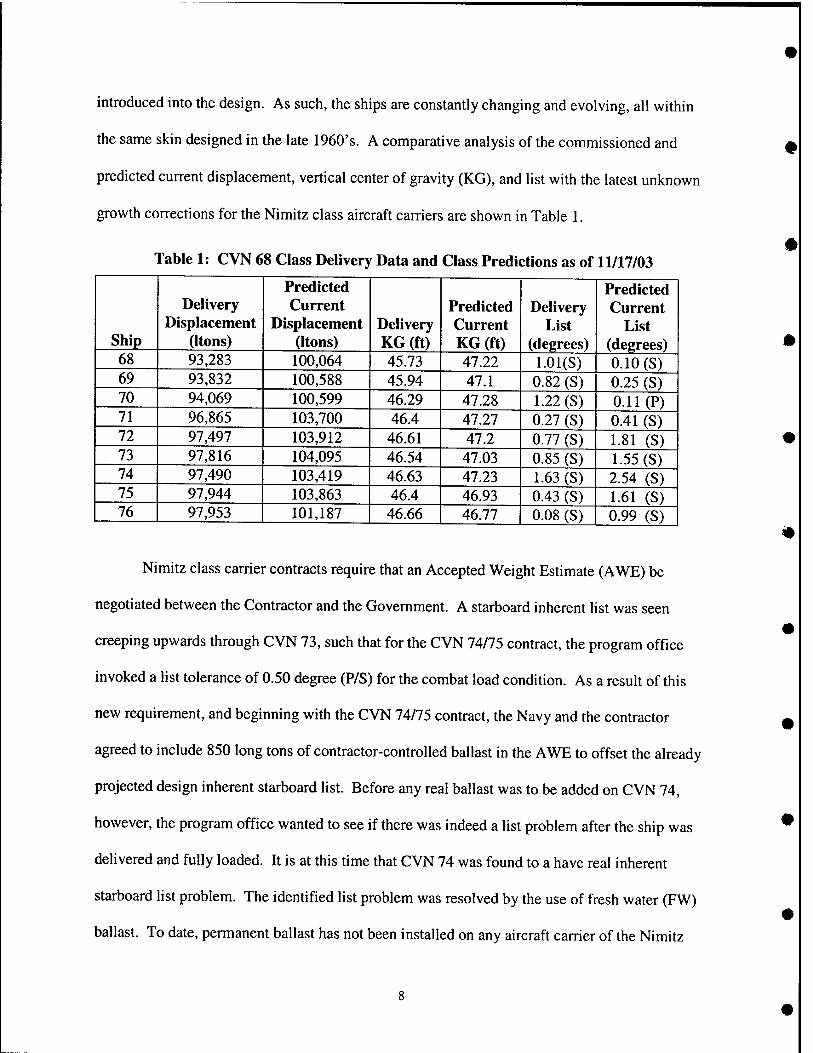
introduced into the design. As such, the ships are constantly changing and evolving, all within
the same skin designed in the late 1960's. A comparative analysis of the commissioned and
predicted current displacement, vertical center of gravity (KG), and list with the latest unknown
growth corrections for the Nimitz class aircraft carriers are shown in Table 1.
Table 1: CVN 68 Class Delivery Data and Class Predictions as of 11/17/03
Ship
Delivery Displacement
(Itons)
Predicted Current
Displacement (Itons)
Delivery KG (ft)
Predicted Current KG (ft)
Delivery List
(degrees)
Predicted Current
List (degrees)
68 93,283 100,064 45.73 47.22 l.Ol(S) 0.10 (S) 69 93,832 100,588 45.94 47.1 0.82 (S) 0.25 (S) 70 94,069 100,599 46.29 47.28 1.22 (S) 0.11 (P) 71 96,865 103,700 46.4 47.27 0.27 (S) 0.41 (S) 72 97,497 103,912 46.61 47.2 0.77 (S) 1.81 (S) 73 97,816 104,095 46.54 47.03 0.85 (S) 1.55 (S) 74 97,490 103,419 46.63 47.23 1.63 (S) 2.54 (S) 75 97,944 103,863 46.4 46.93 0.43 (S) 1.61 (S) 76 97,953 101,187 46.66 46.77 0.08 (S) 0.99 (S)
#
Nimitz class carrier contracts require that an Accepted Weight Estimate (AWE) be
negotiated between the Contractor and the Government. A starboard inherent list was seen
creeping upwards through CVN 73, such that for the CVN 74/75 contract, the program office
invoked a list tolerance of 0.50 degree (P/S) for the combat load condition. As a result of this
new requirement, and beginning with the CVN 74/75 contract, the Navy and the contractor
agreed to include 850 long tons of contractor-controlled ballast in the AWE to offset the already
projected design inherent starboard list. Before any real ballast was to be added on CVN 74,
however, the program office wanted to see if there was indeed a list problem after the ship was
delivered and fully loaded. It is at this time that CVN 74 was found to a have real inherent
starboard list problem. The identified list problem was resolved by the use of fresh water (FW)
ballast. To date, permanent ballast has not been installed on any aircraft carrier of the Nimitz
class. Changes to the CVN 76 design resulted in a reduced starboard list and consequently the
contractor-controlled ballast included in the AWE was reduced to 650 long tons.
From operational experience, it would be safe to say that there is an inherent starboard
list under full fuel load (or virtually full) with the airwing embarked and no flight operations
being conducted on most Nimitz class carriers. When all the planes are stacked on the starboard
side and the ship has just been refueled, the LCS is unable to level the deck. This is when it has
become necessary for some carriers to use fresh water ballast in a number of inner bottom voids
and damage control (DC) voids to correct the adverse list condition. But from a ship
survivability standpoint, and as their name implies, DC voids are not an acceptable list control
measure under normal operating conditions. Maintaining liquid ballast in DC voids reduces the
design counter flooding capability of the ship. None the less, this is how some ships operate in
order to keep the Nimitz class ships at sea.
In February 1999, PEO Carriers issued a Message to the CVN 68 Class identifying
several voids (i.e., non DC voids) that could be used for FW ballasting for ships experiencing list
control problems. Prior to using those voids, however, the message requested the ships to
confirm that the list control difficulties were not the result of abnormal LCS operations or
adverse liquid loading or stores management. Carriers experiencing list control difficulties were
to request approval from the Type Commander (TYCOM) to fill the voids listed in the message.
The approval would remain in effect for that ship until a permanent solution was identified and
implemented.
It is obvious that fixing the inherent list cannot be solved by leaving aircraft behind or by
limiting the load of fuel carried. TYCOM directive states that the JP-5 system is required to
remain at least 60% full at all times. These ships have a very specific warfighting requirement
that must be achieved, and a reduction in capabilities is unacceptable.
There must be a solution to the inherent list problem beyond limiting ships payload or
using the DC voids outside of their designed intent. This report evaluates other alternatives to
finding a solution to fix the inherent list on Nimitz class aircraft carriers.
1.2.1 Past Research
A thesis was performed in 2001 by Michael Malone, a graduate of MIT. His thesis, titled
"An Alternate Method for the Determination of Aircraft Carrier Limiting Displacement for
Strength;" determined that although all Nimitz class aircraft carriers are approaching their
limiting displacement for strength, the traditional methods of such calculations are conservative.
In fact, the Nimitz class carriers can accommodate more weight than previously thought.
Because of this thesis, the U.S. Navy Aircraft Carrier Program Office (PMS 312) later directed
N.S. NAPPI Associates to conduct a detailed analysis on estimating the limiting displacement for
strength. Again, it was proven that the Nimitz class hull is capable of sustaining additional
weights which would exceed the current established limiting displacement for strength.
1.2.2 Stability
The stability status for USN ships is defined in [4] and is supported by [11]. The Chief of
Naval Operations has directed that the Navy's ships will be kept within naval architectural limits
to ensure that essential survivability features are maintained. For each ship class, the Naval Sea
Systems Command's Weights and Stability Division is to keep track of the weight and stability
status, limiting draft and other limitations including being an advocate for weight and moment
status and moment compensation necessary to adhere to the established limits. Surface ships are
10
classified into four status conditions for vertical center of gravity (KG) and limiting drafts. As
specified in [4], the definitions for the status listings are:
• STATUS 1 An increase in weight and a rise of the ship's center of gravity are acceptable. Added weight and moment resulting from changes will not require any compensation unless the magnitude of the additions is so large as to make the ship approach stability limits.
• STATUS 2 Neither an increase in weight nor a rise of a ship's center of gravity can be accepted.
• STATUS 3 An increase in the ship's weight is acceptable, but a rise of the ship's center of gravity must be avoided.
• STATUS 4 A rise of the ship's center of gravity is acceptable, but increase in weight must be avoided. Compensation for added weight may be obtained by removal of an equal or greater weight at any level.
Status 1 is the only acceptable ship status. The goal is for ships in the fleet to remain in
Status 1. In the other three status conditions, the displacement and KG must be closely
monitored to ensure the condition does not worsen and steps must be taken to try to bring the
ship back within acceptable design limits. Typically, when an in-service carrier requires a
modification that will add weight to the ship, it is the responsibility of the program office and the
planning yard to put together a package that includes maintenance and repair items, as well as
modernization changes. First, a preliminary weight estimate of the modernization changes are
put together in the package and made ready for installation. Once the package is installed, the
planning yard or shipyard keeps track of the weights being installed. At the end of the
availability, an actual weight report for the installed changes is generated. This report is passed
from the shipyard to the program office where it is incorporated into the stability baseline of the
pertinent ship.
11
For any configuration changes, such as adding weight to a carrier in Stability Status 2, the
interested party fills out a Justification Cost Form (JCF) with the weight and KG impact as well
as the ship's Stability Status. A Configuration Control Board that includes the Program Office,
the Ship Design Manager, and the necessary Technical Authorities then meet to approve or
disapprove the modification. If approved, an Engineering Change Proposal (ECP) for newly
commissioned ships or a Ship Alteration Request (SAR) for in-service ships is then generated.
The Nimitz class was assigned to Stability Status 2 by the Weight Control and Stability
Division of the Naval Sea Systems Command. This was done as a result of the stability re-
analysis performed on the Nimitz class carriers. The re-analysis revealed the following:
• The originally calculated Allowable KG of 48.50 feet was no longer applicable for this
class of ships. While 48.50 feet is no longer the allowable KG value, it continues to be
the KG comparator for CVN 68 - 77 for contractual reasons.
• The actual damage capability of this class of carriers is not as originally calculated.
• The damage capability of this class decreases as displacement increases.
• It is important for the holding bulkhead to remain intact.
• The 40'-l 1" limiting draft is based on ship geometry limitations.
As a result of the above study, it was determined by that a stability status of 2 should
continue to be assigned to the Nimitz class in order to:
o Control the displacement growth of the class even though some ships are
substantially below the displacement associated with the limiting draft. This is an
acknowledgement that an increased displacement degrades damage stability
capability.
12
o Control the KG growth of the class even though some ships were substantially
below the KG comparator of 48.50 feet. This is an acknowledgement that an
increased KG degrades damage stability capability.
1.2.3 Survivability
Survivability is defined in [10] as the capacity of a ship to absorb damage and maintain
mission integrity. Typically, most decision making regarding survivability is done during the
early trade-off stages of ship design. As a result, it is imperative that naval architectural
parameters be considered over the lifetime of the ship in order to successfully withstand
designated threat levels. Every attempt must be made to prevent any degradation of a warship's
ability to perform its offensive mission, sustain battle damage, and survive. Aircraft carriers are
further defined in [10] as 'capital ships' in that they are expected to survive more than one
weapons hit and return to some level of mission capability. All other ships are only expected to
survive design level damage from a single design level weapon or a single peacetime hazard.
Survivability, weapons effects and operational environments are categorized in terms of
three levels of severity. Level I represents the least severe environment anticipated for a class of
ship, while Level El represents the most severe environment projected for a combatant battle
group and includes their ability to deal with the broad degrading effects of damage from anti-
ship cruise missiles (ASCM). Aircraft carriers and battle force surface combatants are both
considered Level III. Therefore, it is imperative that these ships be operated and maintained as
they were designed. Any digression from operational restrictions and guidelines makes all
analyses irrelevant.
13
1.2.4 Displacement Limits
Because these aircraft carriers are so important and because any reduction in freeboard
will inherently reduce the effectiveness of the torpedo side protection system (TSPS), these ships
are usually displacement critical. The limit is typically expressed in terms of the Full Load
Condition. Following is the criteria Naval Surface Warfare Center (NSWC) Carderock's Weight
Control and Stability Division uses to determine displacement limits for aircraft carriers with a
TSPS:
• Strength: The displacement, with an assumed longitudinal weight distribution, at which the longitudinal bending moments caused by a standardized wave will produce the maximum allowable stress in the ship's hull girder.
• Speed: The displacement for surface warships at which the ships machinery, operating at a specified percent of maximum available power, will drive the ship at the original design speed specified by the ships characteristics considering power plant, RPM and torque limits.
• TSPS: The maximum draft for a surface warship which prevents the top of the TSPS from being immersed more than a specified amount.
• Subdivision: The maximum displacement at which a ship with a TSPS will satisfactorily resist the flooding effects of a specified number of torpedo hits or similar weapons without submerging the margin line at the bow or the stem.
• Damage Stability: The maximum displacement at which a ship with a TSPS will satisfactorily resist the flooding effects of a specified number of torpedo hits or similar weapons while providing adequate stability to resist high static heel angles, resist capsizing, and return to some level of mission capability.
L2.5 KG Limits
The KG Limit for a warship is the maximum height of the vertical center of gravity of the
ship in the Full Load condition. Any Full Load KG below this limit is expected to survive the
hazards of wind, high speed maneuvering or damage, assuming the ship follows its liquid
loading instructions. The Limiting KG is the lowest limit of either the damage stability limit or
14
the intact stability limit. Following is the DDS-079-1 criteria NSWC Carderock's Weight
Control and Stability Division uses to determine stability limits for surface warships with a SPS:
• Intact: 100 Knot Beam Wind - The Full Load KG which will permit the ship to operate in any normal loading condition and survive the heeling force of a fully developed hurricane (assumed as a nominal 100 knots). The ship will retain sufficient stability to absorb higher gusts without being knocked over, and to absorb the dynamic effects of wave action without being rolled over.
• Damage: The Full Load KG Limit for large surface combatants, such as battleships and aircraft carriers which have a side protective system, is associated with the worst possible combination of a specified number of hazards (torpedoes/missiles) which will:
1) Cause the ship to heel to a large initial angle of 15 - 20 degrees, 2) Cause the ship to approach a capsize situation, or 3) Exceed the counter flooding capability to return to limited operation. Limited operation is defined as a heel of less than 5 degrees to operate aircraft (should be 3 degrees for current aircraft) or less than 10 degrees to operate the main turrets.
In any of the above damage conditions the ship must still possess sufficient dynamic stability to resist capsizing moments induced by wind and waves.
1.3 Present Options
1.3.1 Continue to operate using inner bottom and DC voids
Any departure from proper design and operational criteria degrades any analysis
performed. For example, most stability analyses performed assumes that DC voids are used
correctly, the ship is on an even keel, and that the limiting displacement is not exceeded. In fact,
there is an interrelationship between increasing displacement and a number of factors, to include
ship strength, survivability, stability and seakeeping. Increasing the weight, or displacement, of
carriers is a serious concern because any weight increase only serves to reduce the service life of
the ship. It should be noted again that not all carriers use DC voids to augment the LCS, but it is
also uncertain as to how many actually will use them as a last resort.
DC void usage results in a reduction in TSPS defense. The purpose of the TSPS on any
capital ship is to protect the vital spaces of the ship against flooding and/or detonation of stowed
15
ordnance. Vital spaces include magazine and propulsion system spaces. The TSPS provides the
desired protection by being constructed of a series of longitudinal bulkheads nested transversely.
These longitudinal spaces are further subdivided by transverse fluid-tight bulkheads creating a
'honeycomb' arrangement outboard of the vital magazines and machinery spaces. The spaces
thus created between the bulkheads are alternately filled with liquids (fuel oil, JP-5, ballast
water, etc.) or are left empty (damage control voids). The passive protection afforded by this
combination of bulkheads and 'liquid/air layers" serves to absorb, deflect and reject the explosive
force generated by weapons such as torpedoes or mines. Placing liquid in the void layer
combined with an empty liquid layer will be the worst-case scenario, while one or the other will
result in less of a reduction.
Similarly, DC voids are supposed to be used exactly as their name implies, to combat
flooding with the ability to adjust for list and trim in order to continue to fulfill mission
objectives after sustained damage by being able to continue to launch and recover aircraft. The
specified primary purpose of the DC voids is for damage control. Sea chests and valves for
flooding underwater side protection system spaces (DC voids) are required to flood within six
minutes to fill the space to within 1 foot of the full load waterline per section 529i of [6]. In fact,
current stability criteria require that the ship be able to counter flood to return the flight deck to
within 5 degrees of upright after damage. When a ship has to resort to maintaining list by
flooding DC voids, the crew becomes encumbered by a task that should be unnecessary. The
Damage Control Assistant (DCA) and EOOW are drawn away from their normal tasks and into
roles as reactionary problem-solvers, keeping an eye on flight deck aircraft placements, fuel tank
levels, and ship list. This is a poor utilization of manpower, considering the primary duties of the
DCA and EOOW, which are the coordination of damage control actions and the responsibility
16
for ships propulsion, respectively. Also, a ship's crew is continuously rotating. As a result, there
is a continual learning curve that relies on the passage of operational knowledge from generation
to generation. This is not the optimal way to operate a multi-billion dollar asset, and it is in our
best interest to not put the onus of correcting an evolutionary design fault on a crew who will
serve at most a three year tour. Additionally, de-ballasting DC voids is extremely time intensive.
If a real casualty was to occur with the wrong or too many DC voids flooded, there may not be
sufficient time to correct the condition. It is not hard to imagine the disastrous results possible.
1.3.2 Add a list control tank on the port side
The control of permanent lists (static heel angles) by adding an additional list control tank
of the port side could also be considered an option. The LCS is designed to compensate for
variable lists generated by load items that are moved about the ship over short periods of time.
Such loads could be liquids, cargo, stores, vehicles or aircraft. The current Nimitz class LCS
consists often list control tanks, two centrifugal pumps each rated at 1800 gpm at 30 psi, and the
associated piping and valves required to compensate for lists up to 1.5 degrees in 20 minutes.
The system is designed to be filled with seawater (SW) or firemain to 50% of its total capacity of
278,533 gallons. This allows tanks to be filled to 100% on one side while the other side is left
empty.
The problems encountered with using SW in tanks may be conmion knowledge to most
people; however, potential corrosion from using salt water has encouraged some carriers to use
potable water (PW) as a means to fill their list control tanks. The LCS is designed with PW as a
back-up to using SW or firemain. This is advantageous for corrosion issues, but can be a
problem for PW inventory. Any leaks in the system or maintenance requiring system fill and
17
drain could use a large amount of PW. When underway, potable water conservation is of
primary importance.
1.3.3 Move or exchange compartment spaces
Another option is to move or exchange compartment spaces, such as relocating heavy
equipment on the starboard side to the port side and vice versa. The reduction of starboard
moment by the removal or relocation of items of lightship weight would reduce the quantity of
ballast required, but would be very small by comparison to the amount of permanent ballast
required. In order to achieve the necessary list corrections, an enormous amount of weight
would have to be relocated. The costs involved with such an undertaking would be extremely
high.
1.3.4 Convert a current DC void(s) to a JP-5 tank(s) and pump last
Converting portside DC floodable voids into fuel tanks is also an option. This option will
add to the overall weight of the ship and again a reduction in TSPS capability becomes a large
concern as liquid is being placed in the air layer and thus opening a window of vulnerability.
1.3.5 Future ship alterations and modiflcations
It is also possible that future modifications to the Nimitz class aircraft carrier will serve to
provide a port list, thereby reducing the inherent starboard list. Modifications such as replacing
the existing Nimitz class starboard island with the new modified CVN 76 island could serve to
reduce the starboard list. In fact, CVN 76 has had so many design changes that its starboard
inherent list is less than one degree, currently based on preliminary results of its inclining
experiment. List for CVN 76 has not been an issue thus far, however, at the time feedback was
gained, the ship had not been fully loaded out. CVN 76 is slightly different from the other
Nimitz class ships. The weapons elevator is combined into the main structure and the aft mast is
18
combined with the island which is one level shorter. There is also a more realistic protection
scheme such that a space armor concept was employed. On the older islands, such as CVN 73,
Level III protection can be seen throughout the entire island. This includes 40# (1") plating,
whereas the new CVN 76 island has Level II protection in some areas and is thus lighter.
Another option could be to extend the port side flight deck on the old Nimitz class, as
was done on CVN 76. This allowed for more operational flexibility as the forward port jet blast
deflector can now be used to its full extent. In any case, it is important to note that any number
of ship alterations could be made when time and money become available in the future.
1.3.6 Re-examine current List Control System
Fleet feedback was taken into consideration when performing this study. The design of
the current LCS reportedly requires extensive manpower for operations, possesses obsolete
components, and is not integrated with other shipboard liquid-movement functions. The
installed LCS consists of 10 tanks, 2 pumps and 14 associated valves to distribute seawater
ballast as required compensating for lists up to 1.5 degrees. The manually controlled system
uses verbal communications and associated sailor actions for operation.
Much of the fleet feedback received noted that the current LCS provides sufficient
control when the inherent starboard list has been corrected. The fleet also noted, however, that if
correction has not been provided, the LCS alone does not provide ample list correction while at
full combat load (average displacement between 98,000 and 100,000 Itons, mean draft
approximately between 38'10" and 39'10", even liquid distribution, and standard spotting of
aircraft for flight operations). Standard spotting includes F-18s on the 1 and 4 row, hummers
(fleet jargon for the E-2C Hawkeye) in the hummer hole, F-14s on the stem of the flight deck.
19
helicopters and C-2 Greyhounds inboard of the island, cranes aft of the island, and the rest of the
aircraft dispersed between them.
The LCS is currently being automated via the Automated List Control System alteration
(ALCS 9145K). The ALCS provides remote control and monitoring of the aircraft carrier LCS
from Damage Control Central (DCC) and Shaft Alley via a flat panel display. Four existing loop
valves are upgraded from manual to motor operated and are integrated into the control system.
Existing pump controllers are replaced and control of pumps, valves and tank level monitoring
are integrated into a single system with redundant capabilities. The ALCS utilizes commercial-
off-the-shelf components and Navy-owned software to decrease the manpower needed for
operation and maintenance, increase automation, reduce life cycle costs and significantly
improve system reliability. System line-up and tank management is automated and managed
such that tanks can be filled faster, utilizing fewer watchstanders and increasing system
efficiency. Control and monitoring of the LCS is performed from two human-machine interface
(HMI) stations: one in DCC and one in Shaft Alley. The system can also be operated from the
Central Control Station, and operates in both remote and semi-automatic modes.
Very little feedback has been obtained regarding the new ALCS and its improvements to
overall ship operations. To date, installation has been completed on three of the ten planned
carriers. Although the system provides the means to automatically operate pumps and valves,
the capacity of the system has not been changed. To really affect the starboard inherent list,
more ballasting is going to be required. Once the inherent starboard list is fixed, the ALCS will
be extremely advantageous to overall carrier operations.
20
1.3.7 Ballast Addition
1.3.7.1 Water Ballast
Special preparation would be required for all tanks or voids using locked-in water ballast
to correct the starboard inherent list. The sponson voids, in particular, are coated with epoxy over
an inorganic zinc primer; this is suitable for installation of water ballast, but only for a period of
up to five years if it is intact. Preparation of the sponson voids for installation of water would
require inspection and possibly repair of the existing coating systems. Another problem with
using water as a source of ballast is that it is difficult to provide a sufficient amount of water
ballast in a space judicious manner in order to provide enough permanent list correction.
Although water is an inexpensive material, utilities would have to be relocated to other spaces
and the tanks themselves cannot be partially filled.
1.3.7.2 Solid Ballast
For purposes of this project, lead was not considered as an option due to the tremendous
handling expenses and associated carcinogenic problems. Instead, a pumpable slurry of iron-ore,
known as Perma Ballast®, was examined as a possible source of solid ballast. Ballast
Technologies Inc. (BTI) has been a provider and installer of Perma Ballast® since 1983. Their
product is widely acknowledged to be the quickest and most cost-effective method of ballast
installation. All materials, including the fluid used to install the ballast, are naturally occurring,
nontoxic, non-corrosive and environmentally safe. No gases or vapors are generated and no
special handling is required upon installation or removal.
Minimal vessel modification is required to the ship, thereby providing savings to the
shipyard. Jobs are not generally subcontracted out, thereby cutting out the middle man and
making this product more competitive. Prior to installation, engineers and key personnel inspect
21
the vessel to be ballasted and its location. Requirements such as electrical, water, compressed
air, and equipment location are assessed. BTI engineers then submit engineered drawings noting
location of equipment and diagrams of the installation system along with a written operating plan
for the project. BTI uses its own experienced personnel and equipment during ballast
installations to ensure safe, rapid and efficient mobilization, installation, and demobilization.
BTI's ballast materials are mixed with water and pumped to the vessel via a combination
of rigid and flexible pipes. The slurry is pumped in at a controlled velocity in order to assure an
even distribution of the ballast around projections, pipe, and other objects, leaving no voids.
Excess water is removed as the ballast is installed and settles. This ensures that the in-place,
fixed ballast is a dense mass which will not move or shift. Due to BTI's materials and placement
method, no special handling or tank modifications are required.
BTI pretests materials in its laboratory to ensure proper density and uniformity.
Continuous testing is performed during ballast installation to verify installed density. Densities
of materials range from 1501b/ft^ to 3501b/ftl All processes and materials used by BTI are
approved by ASTM, ABS, MARAD, U.S. Navy, U.S. Coast Guard, Del Norske Veritas, and
Lloyds. In fact, Perma Ballast® has already been installed on a number of naval vessels,
particulariy DDG 73,76, and 77. The reason for installation was to correct a Flight II starboard
list. Feedback obtained from these installations described the process as being very smooth and
extremely successful.
There are a number of advantages to using this Perma Ballast®. It is possible that Perma
Ballast® will absorb shock over a limited area and serve to dampen it. Although the individual
particles and the water are incompressible, the Perma Ballast® bed is made up of many very
small particles which are not bound together by anything except gravity. There is approximately
22
2% entrained air (by volume) in the slurry. Some of this air probably remains in the slurry after
settling so it would be fair to say that Perma Ballast® contains about 1-2% (by volume)
compressible components. Water is removed as the material settles, but even after the Perma
Ballast® settles, all of the voids between particles are filled by water. In fact, a settled bed of
Perma Ballast® is an extremely effective barrier against permeation of oxygen - either into the
bed or through it.
1.4 Option Selection
From the options presented above, the choice was made to use solid ballast to correct the
starboard inherent list on the Nimitz class carriers. Based on ballast density, tank location and
capacity, ease of ballast installation, minor tank structural modifications, and a decision making
cost analysis, the Perma Ballast® appears to be the best option for use in correcting the inherent
list on the Nimitz class aircraft carriers and is discussed extensively in Chapter 2.
2.0 Preliminary Analysis and Results
Preliminary analysis began with tank selection to serve as input to the Program of Ship
Salvage and Engineering (POSSE) computer analysis program, discussed later in section 2.2.
Once tanks were selected for ballasting, a naval architectural analysis using POSSE was
performed for 36 scenarios to determine list corrections. These scenarios encompassed
ballasting on the 2°'', 4*, and 8* decks with 200 Ib/ft^ and 325 Ib/ft^ density ballast. Fresh water
was also examined as a possible alternative, but not as extensively as the solid ballast option.
Once a complete set of data was obtained, a decision making cost analysis was performed. This
cost estimation analysis proved that the 200 Ib/ft^ density ballast was the best option. As a result,
all structural analysis was performed using the 200 Ib/ft^ density ballast. Once the structural
analysis was complete, modeling had to be performed again using POSSE. In some cases, a
23
minimum ballast weight was calculated for a particular set of tanks for the prescribed design
criteria. Analysis had to then be performed again in POSSE with these new ballast weights.
Similarly, some of the structural analysis revealed that stiffening was required for plating in
some of the tank bulkheads. This required another cost assessment be performed in order to
achieve accurate cost estimations. So, one can see that this project followed a design spiral
towards to determining the most cost effective and advantageous solid ballasting solution for
correcting the inherent list on the Nimitz class carriers.
2.1 Tank Selection
Tanks selection was based on location and those that were available for ballasting based
on Nimitz class carrier drawings. As mentioned previously, ballasting was accomplished to
relieve up to 3 degrees of list in half degree increments. 30 tanks, primarily in the aft/port voids,
have been identified to accommodate the installation of Perma Ballast® with 200 Ib/ft^ and 325
Ib/ftl There are 3 tanks or sponson voids on the 2"^ deck, 16 tanks on the 4*^ deck, and 11 tanks
on the 8 deck. The methodology utilized was as follows: to correct the most list possible
using the least weight possible. For example, tanks could have been chosen in the order of fill
that were further aft to assist in trim correction, but that does not provide the best list correction
with the least weight addition. Trim was, however, taken into consideration such that any
addition of ballast would not serve to increase the existing trim condition. As a result, all
changes in trim are also closely monitored.
Included in Appendix A is a series of tables providing information on the effects that
each tank would produce if the tank was individually filled to capacity in a combat load
condition with fresh water as well as each of the two ballast density types, 200 Ib/ft^ and 325
lb/ft. This information includes:
24
Tank name
Tank volume
Ballast type density
Tank weight
Initial KG
Initial trim
Initial weight
Final KG
Final trim
Final weight
A KG
A trim
A weight
2.2 Modeling Analysis Performed
POSSE was used to analyze the inherent list for the Nimitz class carrier. POSSE is a
software package of modeling, naval architectural design tools, and intact loading and salvage
analysis tools designed primarily for U.S. Navy salvage response. The Modeling and Naval
Architecture modules are Microsoft DOS® applications packaged through a Windows interface
called the Ship Project Editor. A plan is then developed so that the engineer can evaluate the
ship in various conditions. The collection of conditions represents the steps in the plan to assess
the status of the vessel. POSSE provides an efficient means to develop plans using a tree
structure to allow a hierarchical definition that permits branching to investigate various potential
solutions. Several branches can be developed and viewed concurrently. A condition represents a
25
particular state of the vessel. It includes all load and strength information associated with that
state. For purposes of this thesis, only intact states were analyzed.
Aircraft carrier modeling in POSSE was too cumbersome to analyze for the original DOS
version. In fact, any analysis prior to this thesis would have to been done in sections. With
POSSE 4.0, the complete Microsoft Windows® version, the sections were able to be combined
into a single ship project (.shp) file using the ship project editor. Once the CVN 68 Nimitz Class
hull was put together, a weight ordinate was entered to adjust the lightship data so that it
coincided with the most recent data available. It has been very difficult to determine the exact
inherent list that each carrier exhibits when under combat load conditions due to the "unknown
light ship (LS) growth" associated with each carrier and due to the lack of in-service inclining
experiments performed on Nimitz class carriers. Unknown LS growth is used to term
unattributable changes in displacement and centers of gravity over the ship's service life.
Examples of unknown LS growth include but are not limited to: unauthorized alterations or
installations of equipment, accumulations of paint, deck covering, dead cable runs, old
foundations, undocumented configuration changes affecting weight and KG, and excess and
obsolete repair parts, technical manuals, and paperwork. Naval Sea Systems Command's
Weights and Stability Division has recently revised the unknown light ship (LS) weight and KG
growth data for CVN 71 through CVN 75 based on re-evaluation of the results of the CVN 71
Actual Operating Condition (AOC) Weight Survey and Displacement Test and the CVN 68 Post-
Refueling Complex Overhaul (RCOH) inclining experiment.
The CVN 68 inclining experiment was the first in-service inclining experiment of the
NIMITZ class in 27 years. The CVN 71 displacement test determined the ships displacement
and longitudinal, transverse but not vertical center of gravity. The CVN 68 post RCOH inclining
26
was successfully performed and the results are considered to be accurate. The results of the
inclining show that the ship had an unknown lightship weight growth of 1,818 Itons and 0.47 feet
of KG increase. The fully loaded condition was determined to have a displacement of 100,019
Itons with a KG of 47.21 feet. This provides 3,781 Itons (3.78%) and 1.29 feet KG service life
allowance remaining when compared to the limiting displacement of 103,800 Itons and a KG
comparator value of 48.50 feet.
The following changes were made to all stability baselines for CVN 71-75:
• CVN 71
o Increase the current LS vertical center of gravity by 0.25 feet to account for the
unknown LS KG growth.
• CVN 72-75
o Revise the unknown LS weight growth to 2,333 long tons.
o Locate the unknown LS weight growth at the following centers of gravity:
■ VCG = 60.5 ft
■ LCG = 72.47 ft (A)
■ TCG = 5.62 ft (P)
As a result of this unknown growth, an average Nimitz class carrier baseline condition
was modeled in POSSE and used for all analyses. Lightship and Combat Load Condition data
was obtained from the CVN 72 Weight and Moment Baseline Report. This report is based on:
1) CVN 68 post RCOH inclining experiment load out,
2) CVN 71 Actual Operating Condition (AOC) results,
3) CVN 73 Aircraft/JP-5 Revisions,
4) Scheduled Restricted Availabilities (SRAs) actually accomplished.
27
5) the latest estimates for next overhaul,
6) the latest Availability FYOl Planned Incremental Availability (PIA), and
7) LCS at 50%.
A Lightship Condition of 81,450.69 Itons and a Combat Load Condition of 104,263.10
Itons were obtained from the CVN 72 Weight and Moment Baseline report and used for
modeling purposes. These values are from before the latest correction for unknown growth was
applied. Included in Table 1 are the current CVN class predictions with the most recent
unknown growth corrections applied. This is an extremely important chart because it shows
each carrier's delivery data and class predictions for displacement, KG, and list.
The VCG, LCG, TCG, and volume of each tank being analyzed was then checked and
modified if necessary to ensure accurate stability and analytical results. These naval architecture
parameters were checked against the compartment and access database for CVN 70. Normally,
one would use the ship's lines drawings and develop the hull up to the bulkhead and freeboard
decks (i.e. the highest level to which there will be watertight/structural salvage operations). On
the basis of this modeling, one checks the hydrostatics and curves of form against the builder's
documents to determine if the hull has been modeled correctly. Any freely flooding area above
the freeboard deck will generally be left off the hull model unless the deck is a strength deck (i.e.
part of hull girder bending). The 2"'' deck sponson voids had to be added to the model because
they were not included previously and POSSE is normally only utilized to model what is inside
the ship's hull. Builder's lines drawings were not used, however, because salvage and
hydrostatic work was not needed for purposes of this project. Instead, weights and centers were
input to model the CVN 72 data to determine and correct the ship's list. After careful accounting
28
of each tank's location was added, verified, or corrected, the file was imported into the POSSE
program so that a combat load could be applied.
The combat load condition was then modified to reflect the current CVN 72 baseline
combat load data mentioned previously as constants in the POSSE plan that was newly created.
This includes a correction for:
1) crew and effects,
2) aviation ammunition,
3) ship ammunition,
4) provisions and stores,
5) general stores,
6) lube oil,
7) potable water,
8) reserve and emergency feed water,
9) oxygen and nitrogen production plant,
10) JP-5 aviation fuel,
ll)gasohne,
12) aircraft,
13) aviation yellow gear,
14) aviation lube oil,
15) onboard discharge storage tanks, and
16) bilge and oily water.
Then, to reflect CVN 71 AOC results, a miscellaneous weight correction factor was
added at the combat load condition TCG, VCG, and LCG. Now, the combat load condition was
29
accurate and ready for the creation of several variant conditions. Specifically, a condition for
water ballast, high density ballast (325 Ib/ft^), and low density ballast (200 Ib/ft^) was created.
Included in Appendix B is a series of tables providing POSSE modeling results in a
combat load condition for list correction in half degree increments up to 3 degrees for fresh water
as well as each of the two ballast density types, 200 Ib/ft^ and 325 Ib/ftl This information
includes:
• Tank name
• Tank volume
• Ballast type density
• Tank weight
Degree Increment:
• Weight
• Percent change
• A KG
• A Trim
A 95% usable volume fraction was utilized for all calculations. This value provides for
structural internals as well as for any utilities that may be running through the spaces. There are
no losses due to compaction. According to the vendor, BTI, because the water is removed as the
material settles, all of the voids between particles are filled by water and remain filled by water.
It must be noted again, however, that a settled bed of Perma Ballast® is an extremely effective
barrier against permeation of oxygen - either into the bed or through it.
30
2.3 Preliminary Decision-Making Cost Estimation
All decision making costing or "concept" estimation was performed by Norfolk Naval
Shipyard's Structural Engineering and Planning Office (Code 256). This preliminary costing
was performed prior to any structural analysis. It was presumed that one type of ballast or one
location of ballast could be ruled out solely based on cost alone. As a result, a final cost analysis
would still need to be performed after the structural analysis was completed. Cost estimation
was performed for a combination of 36 scenarios on the 2"'', 4*, and 8* decks. A specific
number of man-hours were allocated under each shop for jobs associated with the installation of
Perma Ballast®. These jobs ranged from the opening and closing of voids to the preparing and
painting of any additional structures. The cost estimation was broken down by man-hours and
then converted to man-days. A total production cost was then derived from the man-days
required for tank prepping the Perma Ballast® installation. Similarly, material production costs
were calculated for prepping a typical void while additional material costs were additionally
applied for canning plate installation on the 2"^" deck. A canning plate, used to enclose only the
required amount of ballast, would only be utilized in analysis of the 2°^ deck because both the 4'
and 8* decks are completely filled in all of the modeling scenarios. Any additional weight added
due to the addition of internal structures or stiffening was also tabulated and tracked.
Because the 4* and 8* decks did not require canning plates, any costing associated with
these decks involved limited material costs and fairly minor production costs. Much of the work
associated with all the tanks includes:
• Opening and closing of tanks
• Touch-up painting
• Removal and reinstallation of accesses
31
• Testing of all accesses
• Removal and reinstallation of any interferences
• Patching and repair of deck coverings
It was assumed that the 2"'' deck would require structural modifications due to thinner shell
plating on the sponsons (compared to thicker hull shell plating found on the 8"' deck voids).
Two sponson voids were analyzed in depth for cost estimation purposes, 2-165-8-V and 2-180-6-
V. All production and material costs were based on prepping and work on the entire tank. As a
result, the 2"'* deck void costs are much higher than the 4"* and 8* deck voids due to their size.
Similarly, a thumb rule was applied to the T"^ deck voids when filled to 95% and no canning pate
work was required. The total structural work, for both production and material costs, is half the
cost of the canning plate work. These cost estimates do not take into account relocation of
existing utilities that may be running through the spaces. An analysis was performed, however,
that determined that ballasting these selected tanks would have little, if any impact on the tanks,
and that relocation of utilities would probably not be required.
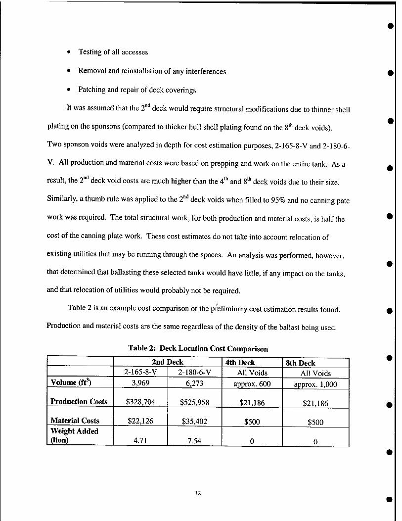
Table 2 is an example cost comparison of the preliminary cost estimation results found.
Production and material costs are the same regardless of the density of the ballast being used.
Table 2: Deck Location Cost Comparison
2nd Deck 4th Deck 8th Deck 2-165-8-V 2-180-6-V All Voids All Voids
Volume (ft') 3,969 6,273 approx. 600 approx. 1,000
Production Costs $328,704 $525,958 $21,186 $21,186
Material Costs $22,126 $35,402 $500 $500 Weight Added aton) 4.71 7.54 0 0
32
All further costing calculations for the 2°'' deck voids less than 95% filled were then
performed as a percentage of the entire tank. For example, if a 2"'' deck sponson void was to be
filled 22%, then the corresponding voids production and material costs were multiplied by 22%.
This was allowable because of the nature of the geometry of the 2°'* deck voids as shown in
Figure 1. Sponson void 2-165-8-V runs 60 feet long and sponson void 2-180-6-V runs 96 feet
long. A detailed production and material cost breakdown for the 36 options mentioned is located
in Appendix C. The worksheets used to perform these cost estimations are also located in
Appendix C. A complete preliminary cost comparison was then performed for the 2° , 4', and
8* decks. This comparison provides the following:
• Total Cost
o Production cost
o Material cost
o Perma Ballast® cost
• Total Weight (Ltons)
o Material Weight
o Perma Ballast® Weight
• A KG
This decision making cost comparison revealed that the 200 Ib/ft^ density Perma Ballast®
was much more economical than the 325 Ib/ft^ density Perma Ballast®. It takes nearly the same
amount of ballast to affect each incremental degree change on the same deck regardless if using
the 200 Ib/ft^ or 325 Ib/ft^. Although the number of tanks required to ballast with 200 Ib/ft^ was
higher, it was still more cost effective to use the 200 Ib/ft^ density ballast due to the price per Iton
of the 325 Ib/ft^ ballast. The 325 Ib/ft^ ballast has steel shot added to it to help achieve its high
33
density. It was also discovered at this early stage of analysis that for corrections at or beyond 1.5
degrees, the 2" deck was a much better location for this ballast addition due to the lesser weight
addition resulting from the larger moment arm generated by filling the 2"'' deck voids. The costs
associated with adding ballast to the 2"'' deck is much higher, but the amount of ballast required
is significantly less than that required for the 4"" and 8"' decks. For corrections less than 1.5
degrees, the 2" deck and the 8"" decks have a fairly comparable weight addition, however,
ballasting the 8' deck tanks costs significantly less. The complete preliminary cost comparison
for the 2"^ 4*^, and 8'" decks is found in Appendix D.
Adding ballast to the 2"'' deck voids does increase KG and thus reduces the KG service
life allowance margin; however, the increase seen is fairly small. In fact, as shown in Appendix
D, a 1.5 degree list correction results in approximately a 0.1 percent KG increase. On average,
the Nimitz class carriers currently have a KG of 47 feet, as shown in Table 1. The goal KG
service life allowance is not to exceed 48.5 feet. Thus, to fix an inherent list of 1.5 degrees, there
would be a .05 foot increase in KG.
34
2.4 Structural Analysis
One tank on each deck was chosen for structural analysis due to the geometrical
similarities between tanks. Analysis was performed on any existing shell and/or deck plating, as
well as all longitudinal and transverse bulkheads for the tank chosen from each deck. The
volume of each tank was obtained from POSSE so that the weight of Perma Ballast® required to
fill the entire tank could be calculated in Itons. The density used for all the Perma Ballast®
calculations was 200 Ib/ft^. All structural calculations are located in Appendix E.
All surface ships shall be designed to withstand a number of loading conditions including
ship motion loads. Ship motion loads are defined by [6] as the inertia forces and gravity
components resulting from the motion of the ship in a seaway. The ship motion factors for this
analysis were obtained from Naval Sea Systems Command's Ship Survivability Division.
Although these factors will vary slightly depending on location, they were assumed to be
constant. They are as follows:
Ship Motion Factors:
V:=1.25 Vertical
A := 0.75 Athwartship
F := 0.4 Fore/Aft
Once the ship motion factors were applied to each direction respectively, the total normal
force could be calculated. The force affecting the structural analysis was dependent on the
location of the deck or bulkhead being analyzed. For example, the total force acting on the 2"
deck's sponson shell plating had to be resolved from both a vertical and athwartship force. The
resulting pressure, or equivalent head, on the plating was then found using this resolved normal
force. Each tank was based on a 95% usable volume to account for structural internals or
utilities running through the space.
35
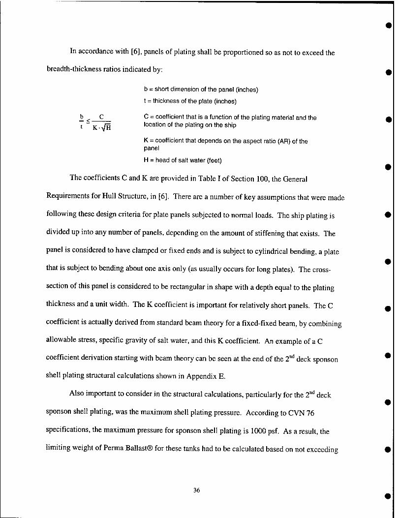
In accordance with [6], panels of plating shall be proportioned so as not to exceed the
breadth-thickness ratios indicated by:
b = short dimension of the panel (inches)
t = thickness of the plate (inches)
_b ^ C C = coefficient that is a function of the plating material and the t ~ K • -V/H location of the plating on the ship
K = coefficient that depends on the aspect ratio (AR) of the panel
H = head of salt water (feet)
The coefficients C and K are provided in Table I of Section 100, the General
Requirements for Hull Structure, in [6]. There are a number of key assumptions that were made
following these design criteria for plate panels subjected to normal loads. The ship plating is
divided up into any number of panels, depending on the amount of stiffening that exists. The
panel is considered to have clamped or fixed ends and is subject to cylindrical bending, a plate
that is subject to bending about one axis only (as usually occurs for long plates). The cross-
section of this panel is considered to be rectangular in shape with a depth equal to the plating
thickness and a unit width. The K coefficient is important for relatively short panels. The C
coefficient is actually derived from standard beam theory for a fixed-fixed beam, by combining
allowable stress, specific gravity of salt water, and this K coefficient. An example of a C
coefficient derivation starting with beam theory can be seen at the end of the 2"^* deck sponson
shell plating structural calculations shown in Appendix E.
Also important to consider in the structural calculations, particularly for the 2"'^ deck
sponson shell plating, was the maximum shell plating pressure. According to CVN 76
specifications, the maximum pressure for sponson shell plating is 1000 psf. As a result, the
limiting weight of Perma Ballast® for these tanks had to be calculated based on not exceeding
36
this pressure. This resulted in a reduction of approximately 55 Itons of ballast, for this particular
case only. Similarly, the only structural analysis performed for the 4* deck void was on its deck
plating. Once it was determined that deck stiffening would be required, the 4* deck tanks were
taken out of consideration as a possible location for placing this ballast. Although adding a
stiffener down the middle of the deck plating would alleviate any structural concerns, welding to
the deck plating would have to be performed. With welding required on the bottom deck plating,
a watch would need to be stationed on the other side of the deck. The tanks below these 4 deck
tanks are foam filled and a fire watch cannot be stationed in these tanks.
Once a maximum pressure in head of water was calculated, the breadth-thickness ratio
formula could be used again to determine the stiffener spacing or limiting short dimension of the
panel. If the calculated maximum distance that the stiffeners can be located apart fell less than
the actual stiffener spacing, then no plastic deformation would occur and stiffening of the plating
was not required. If stiffening was required, then the panel thickness was usually divided in half
to accommodate the calculated pressure.
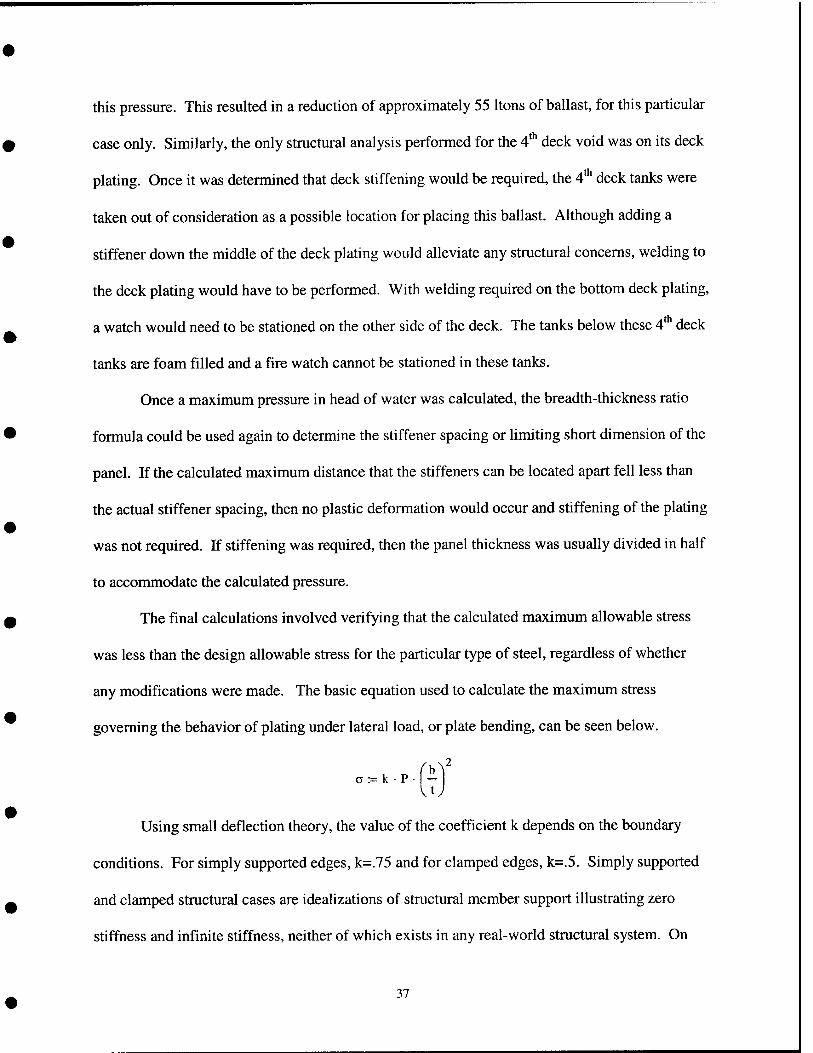
The final calculations involved verifying that the calculated maximum allowable stress
was less than the design allowable stress for the particular type of steel, regardless of whether
any modifications were made. The basic equation used to calculate the maximum stress
governing the behavior of plating under lateral load, or plate bending, can be seen below.
Using small deflection theory, the value of the coefficient k depends on the boundary
conditions. For simply supported edges, k=.75 and for clamped edges, k=.5. Simply supported
and clamped structural cases are idealizations of structural member support illustrating zero
stiffness and infinite stiffness, neither of which exists in any real-world structural system. On
37
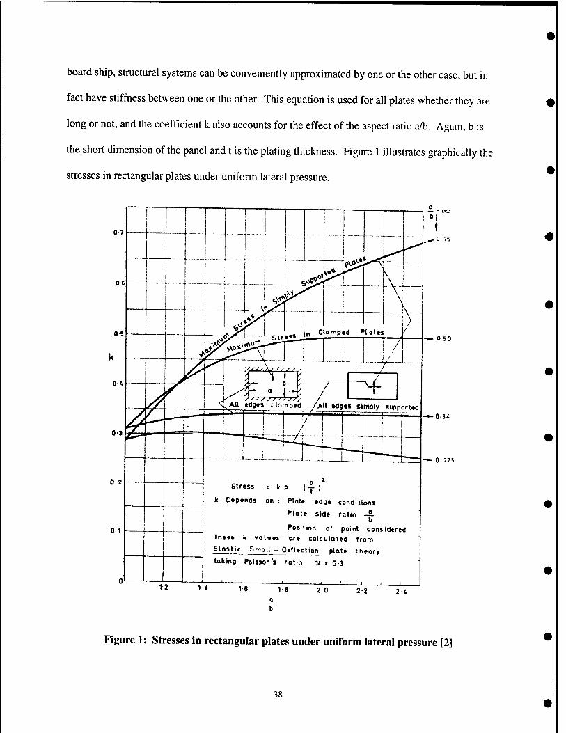
board ship, structural systems can be conveniently approximated by one or the other case, but in
fact have stiffness between one or the other. This equation is used for all plates whether they are
long or not, and the coefficient k also accounts for the effect of the aspect ratio a/b. Again, b is
the short dimension of the panel and t is the plating thickness. Figure 1 illustrates graphically the
stresses in rectangular plates under uniform lateral pressure.
Of
— 050
k P l-j- ) Stress
k Depends on : piatt edge conditions
Plote side ratio — b
Position of point considered These k values are calculated from
Elastic Small - Deflection plote theory
j taking Poisson's rotio i) « 0-3
12 14 1-6 18 2 0
-^ 0 225
2 2 2 i
Figure 1: Stresses in rectangular plates under uniform lateral pressure [2]
38
2.4.1 Structural Modifications
2.4.1.1 Modifications to the 2'"' Deck
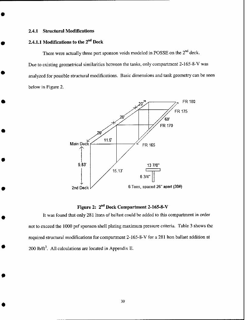
There were actually three port sponson voids modeled in POSSE on the 2° deck.
Due to existing geometrical similarities between the tanks, only compartment 2-165-8-V was
analyzed for possible structural modifications. Basic dimensions and tank geometry can be seen
below in Figure 2.
Main Deck 4^
9.83'
2nd Deck
FR 180
FR 175
6 3/4"
S Tees, spaced 25" apart {30#)
Figure 2: 2°" Deck Compartment 2-165-8-V
It was found that only 281 Itons of ballast could be added to this compartment in order
not to exceed the 1000 psf sponson shell plating maximum pressure criteria. Table 3 shows the
required structural modifications for compartment 2-165-8-V for a 281 Iton ballast addition at
200 Ib/ft^. All calculations are located in Appendix E.
39
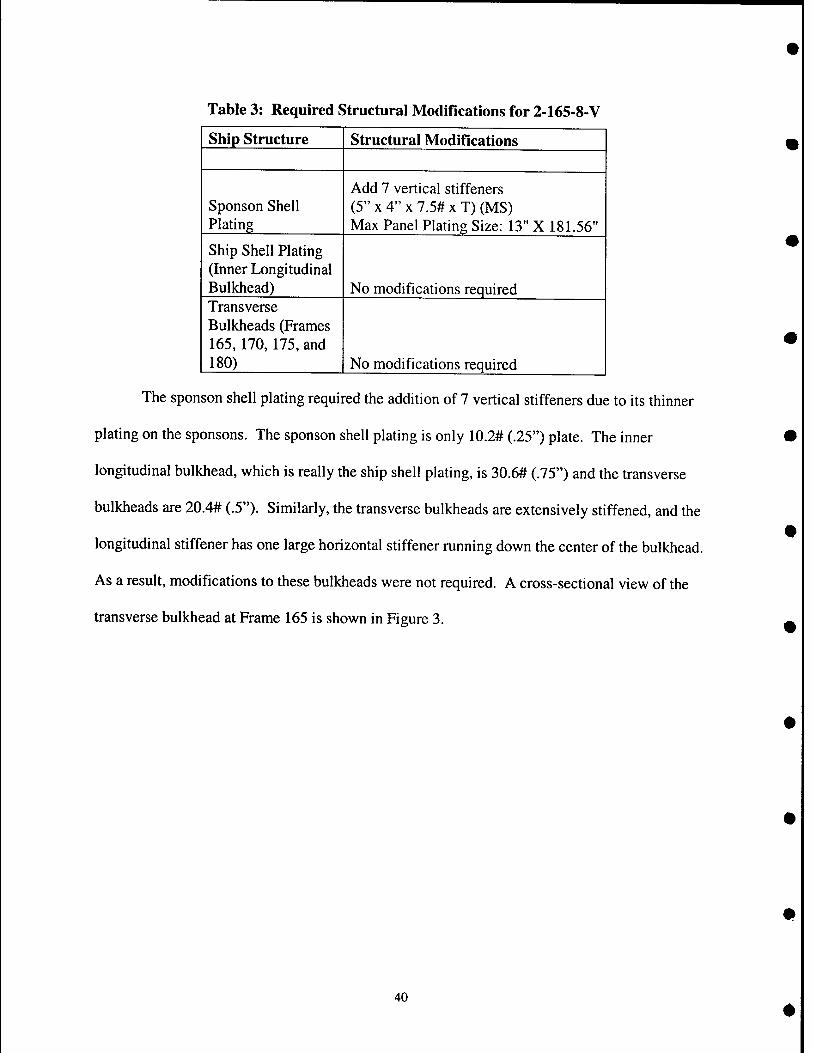
Table 3: Required Structural Modifications for 2-165-8-V
Ship Structure Structural Modiflcations
Sponson Shell Plating
Add 7 vertical stiffeners (5" X 4" X 7.5# X T) (MS) Max Panel Plating Size: 13" X 181.56"
Ship Shell Plating (Inner Longitudinal Bulkhead) No modifications required Transverse Bulkheads (Frames 165,170,175, and 180) No modifications required
The sponson shell plating required the addition of 7 vertical stiffeners due to its thinner
plating on the sponsons. The sponson shell plating is only 10.2# (.25") plate. The inner
longitudinal bulkhead, which is really the ship shell plating, is 30.6# (.75") and the transverse
bulkheads are 20.4# (.5"). Similarly, the transverse bulkheads are extensively stiffened, and the
longitudinal stiffener has one large horizontal stiffener running down the center of the bulkhead.
As a result, modifications to these bulkheads were not required. A cross-sectional view of the
transverse bulkhead at Frame 165 is shown in Figure 3.
40
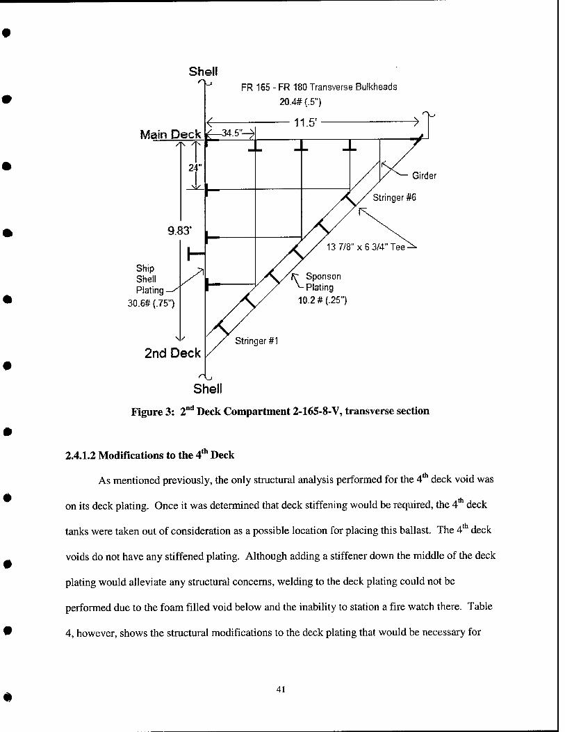
Shell
Main Deck
FR 165 - FR 180 Transverse Bulkheads
20.4# (.5")
11.5' >
Girder
Stringer #6
13 7/8" X 6 3/4" Tee-
Ship Shell Plating
30.6# (.75")
2nd Deck
fr Sponson ^Plating 10.2 #(.251
Stringer #1
Shell
Figure 3: 2 Deck Compartment 2-165-8-V, transverse section
4 th
ith
2.4.1.2 Modifications to the 4" Deck
As mentioned previously, the only structural analysis performed for the 4"^ deck void was
on its deck plating. Once it was determined that deck stiffening would be required, the 4 deck
tanks were taken out of consideration as a possible location for placing this ballast. The 4' deck
voids do not have any stiffened plating. Although adding a stiffener down the middle of the deck
plating would alleviate any structural concerns, welding to the deck plating could not be
performed due to the foam filled void below and the inability to station a fire watch there. Table
4, however, shows the structural modifications to the deck plating that would be necessary for
41
compartment 4-165-4-V for a 50 Iton ballast addition at 200 Ib/ftl All calculations are located in
Appendix E.
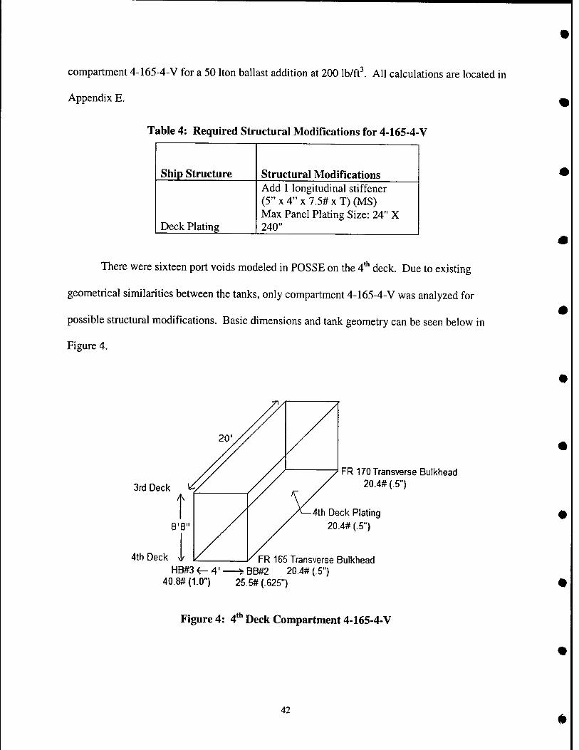
Table 4: Required Structural Modifications for 4-165-4-V
Ship Structure Structural Modifications
Deck Plating
Add 1 longitudinal stiffener (5" X 4" X 7.5# X T) (MS) Max Panel Plating Size: 24" X 240"
There were sixteen port voids modeled in POSSE on the 4"' deck. Due to existing
geometrical similarities between the tanks, only compartment 4-165-4-V was analyzed for
possible structural modifications. Basic dimensions and tank geometry can be seen below in
Figure 4.
3rd Deck
4th Deck
FR 170 Transverse Bulkhead 20.4# {.5")
4th Deck Plating 20.4# (.5")
FR 165 Transverse Bulkhead HB#3 4-4' ^BB#2 20.4# (.5")
40.8#(1.0") 25.5#(.625")
<th Figure 4: 4' Deck Compartment 4-165-4-V
42
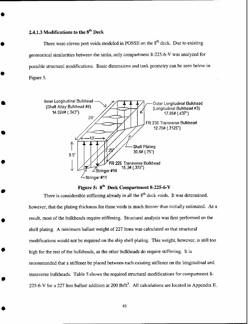
2.4.1.3 Modifications to the 8* Deck
There were eleven port voids modeled in POSSE on the 8* deck. Due to existing
geometrical similarities between the tanks, only compartment 8-225-6-V was analyzed for
possible structural modifications. Basic dimensions and tank geometry can be seen below in
Figure 5.
Innsr Longitudinal Bulkhead (Shaft Alley Bulkhead #4)
14.024# (.343")
Outer Longitudinal Bulkhead (Longitudinal Bulkhead #3)
17.85# (.437')
FR 230 Trans^/erse Bulkhead 12:75# (.3125")
Shell Plating 30.S# (.75")
FR 225 Transverse Bulkhead 'Q.- ^-1. 15.3#(.375l , —Stringer #14
^Stringer #11
Figure 5: 8* Deck Compartment 8-225-6-V
There is considerable stiffening already in all the 8* deck voids. It was determined,
however, that the plating thickness for these voids is much thinner than initially estimated. As a
result, most of the bulkheads require stiffening. Structural analysis was first performed on the
shell plating. A minimum ballast weight of 227 Itons was calculated so that structural
modifications would not be required on the ship shell plating. This weight, however, is still too
high for the rest of the bulkheads, as the other bulkheads do require stiffening. It is
recommended that a stiffener be placed between each existing stiffener on the longitudinal and
transverse bulkheads. Table 5 shows the required structural modifications for compartment 8-
225-6-V for a 227 Iton ballast addition at 200 Ib/ft^. All calculations are located in Appendix E.
43

Table 5: Required Structural Modifications for 8-225-6-V
Ship Structure
Shell Plating
Structural Modiflcations
No modifications required
Inner Longitudinal Bulkhead (Shaft Alley Bulkhead #4)
Add 5 vertical stiffeners (5" X 4" X 7.5# X T) (MS) Max Panel Plating Size: 24" X 114"
Outer Longitudinal Bulkhead (Bulkhead #3)
Add 5 vertical stiffeners (5" X 4" X 7.5# X T) (MS) Max Panel Plating Size: 24" X 87"
Transverse Bulkhead (Frame 225)
Add 4 vertical stiffeners (5" X 4" X 7.5# X T) (MS) Max Panel Plating Size: 15" X 114" *Note-panel height is dependent on trapezoidal geometry
Transverse Bulkhead (Frame 230)
Add 4 vertical stiffeners (5" X 4" X 7.5# X T) (MS) Max Panel Plating Size: 15" X 114" *Note-panel height is dependent on trapezoidal geometry
3.0 Final Analysis and Results
This project design spiraled toward finding the most cost effective and advantageous
solid ballasting solution for correcting the inherent list on the Nimitz class carriers. The
preliminary decision-making cost estimation proved that the 200 Ib/ft^ density was the most cost
effective for the same amount of ballast weight. The 325 Ib/ft^ ballast was so much more
expensive, that although the number of tanks required to ballast with 200 Ib/ft^ was higher, it was
still more cost effective to use the 200 Ib/ft^ density ballast. Once the structural analysis was
complete, the minimum ballasting weights that were found had to be analyzed in POSSE again.
For this analysis, the 4'*' deck was eliminated completely due to its structural limitations.
Similarly, any required structural modifications that were not already included in the cost
estimations had to be taken in to account for both the 2"'' and S"' decks.
44
3.1 Final POSSE Results
The minimum amount of 200 Ib/ft^ ballast that could be added to compartment 2-165-8-V
was found to be 281 Itons which corresponds to 79% of that compartment's total capacity. Up
until this point, all tanks had been analyzed to 95% of total capacity due to structural internals or
possible utilities running through the space. Structural analysis was then performed for
compartment 2-180-6-V. A minimum ballast weight of 448 Itons was calculated so that the
maximum pressure design criterion of 1000 psf was not violated. Because less ballast could be
added to these tanks, the POSSE analysis had to be expanded to include compartment 2-250-4-V.
These new results for the 2""^ deck had little effect on KG and only enhanced the aft trim
correction.
The minimum amount of 200 Ib/ft^ ballast that could be added to compartment 8-225-6-V
was 227 Itons. This was calculated to avoid performing structural modifications on the ship shell
plating. As a result, only 90% of that compartment's total capacity could be utilized which was
5% less than originally analyzed in POSSE. This time, rather than perform a structural analysis
on all the 8* deck voids, a maximum capacity thumb rule of 90% was applied to all the 8"' deck
voids. As a result, different tanks were selected and analyzed to achieve the least Iton addition
for the same incremental change in degrees. Again, this had little effect on KG and change in
trim.
A table providing POSSE modeling results in a combat load condition for list correction
in half degree increments up to 3 degrees for 200 Ib/ft^ is included in Appendix F. This
information includes:
• Tank name
• Tank volume
45
• Ballast type density
• Tank weight
Degree Increment:
• Weight
• Percent change
• A KG
• A Trim
3.2 Final Cost Estimation
Once the POSSE modeling analysis was complete, a final cost assessment was made
based on the new results for list correction in half degree increments up to 3 degrees for the T^
and 8"" deck tanks. Because the 8'*' deck tanks now had to be stiffened, the material costs and
material weights had to be determined. The production costs were assumed to be the same. This
information is included in Appendix G. Also, analysis on the T^ deck revealed that
compartment 2-250-2-V had to be used when trying to correct 3 degrees of list. Code 256
provided production and material costs as well as the material weights for tank prepping the
Perma Ballast® installation.
All cost estimations were calculated and derived as previously discussed in the
preliminary cost estimation section. This time, however, 2"^* deck tanks were based on
approximately 80% fillable capacity and S"" deck tanks were based on approximately 90%
finable capacity. When filled to these capacities, canning plate work was not required.
Similarly, any additional weight added due to the addition of internal structures or stiffening was
again tabulated and tracked. Table 6 shows the total cost, total weight addition, and change in
KG for each half degree increment on both the T^ and 8'*' decks.
46
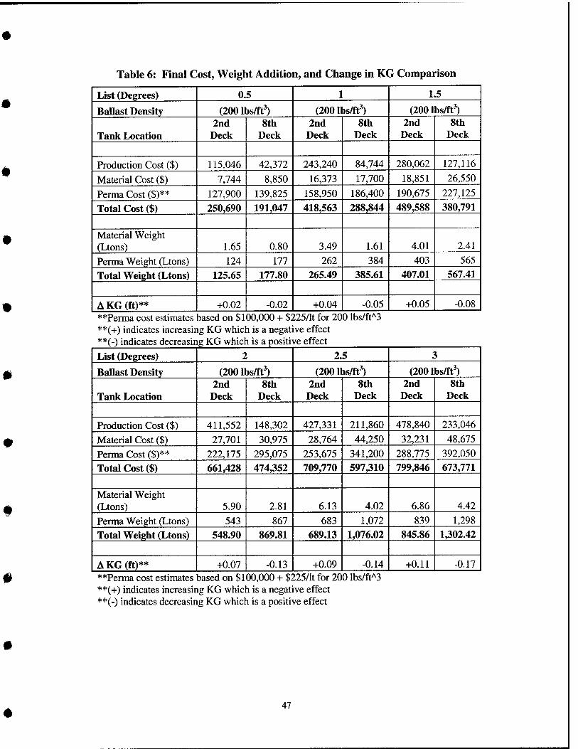
Table 6: Final Cost, Weight Addition, and Change in KG Comparison
List (Degrees) 0.5 1 1.5
Ballast Density (200 lbs/ft') (200 lbs/ft^) (200 lbs/ft^)
Tank Location 2nd
Deck 8th
Deck 2nd
Deck 8th
Deck 2nd
Deck 8th
Deck
Production Cost ($) 115,046 42,372 243,240 84,744 280,062 127,116
Material Cost ($) 7,744 8,850 16,373 17,700 18,851 26,550
Perma Cost ($)** 127,900 139,825 158,950 186,400 190,675 227,125
Total Cost ($) 250,690 191,047 418,563 288,844 489,588 380,791
Material Weight (Ltons) 1.65 0.80 3.49 1.61 4.01 2.41
Perma Weight (Ltons) 124 177 262 384 403 565
Total Weight (Ltons) 125.65 177.80 265.49 385.61 407.01 567.41
A KG (ft)** +0.02 -0.02 +0.04 -0.05 +0.05 -0.08 **Perma cost estimates 5asedon $1 00,000 + $: >25/lt for 200 lbs/ft'^3 **(+) indicates increasing KG which is a negative effect **(-) indicates decreasing KG which is a positive effect
List (Degrees) 2 2.5 3
Ballast Density (20011 bs/ft^) (20011 t>s/ft') (2001 bs/ft^)
Tank Location 2nd
Deck 8th
Deck 2nd
Deck 8th
Deck 2nd
Deck 8th
Deck
Production Cost ($) 411,552 148,302 427,331 211,860 478,840 233,046
Material Cost ($) 27,701 30,975 28,764 44,250 32,231 48,675
Perma Cost ($)** 222,175 295,075 253,675 341,200 288,775 392,050
Total Cost ($) 661,428 474,352 709,770 597,310 799,846 673,771
Material Weight (Ltons) 5.90 2.81 6.13 4.02 6.86 4.42
Perma Weight (Ltons) 543 867 683 1,072 839 1,298
Total Weight (Ltons) 548.90 869.81 689.13 1,076.02 845.86 1302.42
A KG (ft)** +0.07 -0.13 +0.09 -0.14 +0.11 -0.17 **Perma cost estimates jased on $1 00,000 + $: I25l\i for 20 0 lbs/ft'^3 **(+) indicates increasing KG which is a negative effect **(-) indicates decreasing KG which is a positive effect
47
3.2.1 Ease of Removal
As mentioned previously, Perma Ballast® is removable. In fact, removal costs were ^
assessed as well for this project on a per tank basis. For the purposes of this thesis, all tank
prepping costs for ballast removal by BTI were also calculated by Norfolk Naval Shipyard (Code
256). It was estimated that it would cost approximately $78,652 for labor and material to
remove/reinstall accesses and interferences for one 8"" deck tank, and approximately $63,412 for
labor and material to remove/reinstall accesses for one 2"^* deck tank.
Ballast removal costs were also obtained from BTI. It was determined that it would be
best for BTI to actually remove the ballast and dispose of it due to the high costs involved should
a naval shipyard need to dispose of the ballast. For ballast removal, BTI will charge a fixed fee •
of $100,000 for locating and utilizing their equipment and approximately $395 to remove the
ballast per Iton. They also estimated approximately $65 per Iton to dispose of it. All pricing is
I* based on disposal of 100% of the water used to re-slurry the material.
For example, a 1.5 degree list correction would require approximately 400 Iton of ballast
and would need to be removed from two 2"*^ deck tanks. This would result in a total removal ^
cost of $347,412 of which $284,000 is for the ballast removal and $63,412 is for removing and
reinstalling accesses. It should be noted that this ballast addition is only as permanent a solution
as it needs to be. For example, should future modifications entail replacing the old Nimitz island ^
with a new CVN 76 island, it would then be desirable and cost effective to remove this ballast.
3.2.2 Evidence Perma Ballast® is non-corrosive
Recently, the American Bureau of Shipping (ABS) required a sealift conversion vessel
that installed this Perma Ballast® in 1984 to remove its ballast. Concern had arisen because a
tank inspection revealed that corrosion coupons had undergone significant weight loss. ti
48
Corrosion coupons are placed in all tanks that have Perma Ballast® installed so that periodic
tank inspections can be made to determine if corrosion exists. It turned out that the corrosion
coupons were improperly attached to the manhole covers and only rested in the tops of the beds
of Perma Ballast®. The corrosion coupons should be hung on chains and buried within the bed
of ballast. Over the years, the coupons were repeatedly exposed to air and water during
inspections, rather than being properly re-installed into the Perma Ballast®. ABS did report,
however, that all 4 of the tanks were in perfect condition after the Perma Ballast® removal,
almost 20 years after initial installation. Actual cost data was also obtained from this vessel.
The cost to cut into 8 compartments and remove the ballast was approximately $250,000. The
cost to replace the steel and reweld the hull after the ballast was reinstalled was approximately
$100,000. As one can see, the removal costs are relatively low and experience proves that
corrosion will not be a concern.
49
th
4.0 Conclusion
Solid ballast is the most advantageous solution for correcting the inherent list on the
Nimitz class aircraft carriers. Table 6 illustrates that there are a number of advantages and
disadvantages that must be considered when determining the proper location for the Perma
Ballast®.
• The 2" deck is the choice location for list corrections at or beyond 1.5 degrees.
The costs associated with adding ballast to the 2"^^ deck is much higher, but the
amount of ballast required is significantly less than that required for the 4'^ and 8
decks.
o Advantages:
■ significantly less weight added
o Disadvantages:
■ more costly
■ increased KG*
• For list corrections less than 1.5 degrees, the choice location is the S'*' deck. Less
than 1.5 degrees, the 2"'' and 8"" decks have a fairly comparable weight addition,
however, ballasting the 8'*' deck tanks costs significantly less.
o Advantages:
■ significantly less costly
■ decreased KG*
o Disadvantages:
■ increased weight addition
*Any positive change in KG serves to reduce the remaining KG service life allowance. The
average KG service life allowance remaining for most carriers is approximately 1.5 feet. Even
the greatest list correction of 3 degrees is only a 7% reduction in the remaining KG service life
allowance for the aircraft carriers.
50
5.0 Recommendations
1. As can be seen in Table 1, most of the Nimitz class aircraft carriers currently have an
average list of approximately 1.5 degrees. It is recommended that the ships be ballasted on the
T^ deck at this point to avoid adding excess ballast as mentioned previously. The cost is
approximately 22% higher, but the weight addition is approximately 28% less. This is a
considerable amount of weight reduction. The displacement service life allowance must also be
analyzed. If you assume a contract displacement of 100,000 long tons with a 5% service life
displacement allowance for an in-service carrier, then 400 long tons to correct 1.5 degrees of
inherent list would be less than 1/10 of the service life (100,000 * .05 = 5,000 Itons and 400 /
5000 is approx. 8%). This can be viewed as a significant change in displacement or a relatively
small change in displacement when looking at all the advantages that come with correcting the
inherent list on the Nimitz class carriers. Also, the cost per Iton for a 1.5 degree list correction is
approximately $1,200. This is truly inexpensive from a survivability standpoint and also reduces
the operational constraints placed on the ship.
2. The prudent manner in which to handle the inherent list associated with each aircraft
carrier is to perform an inclining experiment on each carrier. The inclining experiment data can
then be used to assess the amount of ballast necessary for installation and can be conducted when
each ship's operational schedule will permit it. As mentioned previously, much of the data for
each carrier has been extrapolated from re-evaluation of the results of the CVN 71 Displacement
Test and the CVN 68 Post-RCOH inclining experiment. Knowing that these tests are extremely
expensive and that CVN 71-75 are the carriers in need of list correction, perhaps an inclining
experiment could be performed on one of these carriers so that data could then be extrapolated
further.
51
3. Until this point, there has been Httle mention of what reducing the inherent list could
do for manpower reduction. The number of man-hours that could be saved due to fixing this
problem could far outweigh anything discussed in this project so far. This is certainly something
that should be studied and investigated as well.
^
52
References
[I] Design Data Sheet 079-1, "Stability and buoyancy of U. S. Naval Surface Ships," Department of the Navy, Naval Ship Engineering Center.
[2] Hughes, Owen F., "Ship Structural Design: A Rationally-Based, Computer-Aided Optimization Approach," The Society of Naval Architects and Marine Engineers, 1988.
[3] NAVSEA 0900-LP-097-4010, "Structural Design Manual For Naval Surface Ships," Department of the Navy, Naval Sea System Command, 15 December 1976.
[4] NAVSEAINST 9096.3D, "Weight and Moment Compensation and Limiting Drafts for Naval Surface Ships," Department of the Navy, Naval Sea Systems Command, 16 August 2001.
[5] NAVSEAINST 9096.6B, "Policy for Weight and Vertical Center of Gravity Above Bottom of Keel (KG) Margins for Surface Ships," Department of the Navy, Naval Sea Systems Command, 16 August 2001.
[6] NAVSEA S9AA0-AA-SPN-010, "General Specification for Ships of the United States Navy," Department of the Navy, Naval Sea Systems Command, 1991.
[7] Nimitz Class Ship Specifications
[8] Nimitz Class Ship Characteristics and Drawings
[9] N.S. NAPPI ASSOCIATES, INC, "Investigation of an Alternative Method for Determining the Limiting Displacement for Strength for CVN 68-CVN 70 Ships," Rockville, Maryland, January 2003.
[10] OPNAVINST 9070.1, "Survivability Policy for Surface Ships of the U. S. Navy," Department of the Navy, Office of the Chief of Naval Operations, 23 September 1988.
[II] OPNAVINST 9096.1, "Weight and Stability Limits for Naval Surface Ships," Department of the Navy, Office of the Chief of Naval Operations, 12 November 1985.
[12] Malone, Michael L., "An Alternate Method for the Determination of Aircraft Carriers Limiting Displacement for Strength," Master's Thesis, Massachusetts Institute of Technology, June 2001.
[13] Roark, Raymond J., "Formulas for Stress and Strain," McGraw-Hill Book Company, 1975.
[14] USS Dwight D. Eisenhower (CVN 69) Engineering Department Standing Order 05, "List Control System Management," Engineering Department, USS Dwight D. Eisenhower (CVN 69), 30 December 1999.
53
Appendix A: Tank Location Study
54
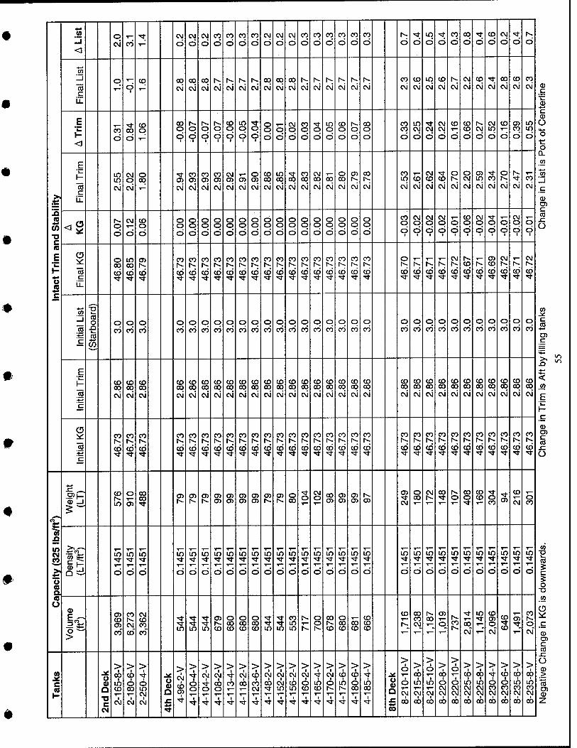
^
<
O CO
■*. CM
d CVI
d CVI
d CO
d CO
d CO
d CO
d CVI
d CVI
d CVI
d CO
d CO
d CO
d CO
d CO
d CO
d d d in d d
CO
d 00 d d
CD
d cvi d d d
CO LI
«
LL
q 5 CO 00 cvj
00 cvi
00 cvi cvi cvi cvi cvi
CO
cvi 00 cvi
oo cvi
1^
cvi 1^
cvj cvi cvi 1^
cvi cvi CO
cvj CD
cvj in cvi
CO
cvi cvi CVI
cvi CO
cvi cvi 00 cvj
CO
cvi CO
cvi
E k. H <1
d S C3
CD q 00 o d
1
o cp
o d
t
o d
1
8 d
1
in o d
1 d
8 d
o d
CVI o d
CO o d
o d
in o d
CD o d d
00 o d
CO CO
d in CVI
d CVI
d CVI CVI
d CD
d CD CD
d cvi d
CVI in d
CD
d d in in d
E
1- 75 c
in LO
CM O
cvi
o q cvi
CO 05 cvi
CO
cvi
CO en cvi
CVI O) cvi cvi
o
cvi
CO q cvi
in 00 cvi
00 cvi
CO oo cvi
CVI oo cvi cvi
o 00 cvi
05 1^ cvi
00 1^ cvi
CO in cvi
5 cvi
CVI CD
cvi CO
cvi
o
cvi
o CVI
cvi
Oi in cvi cvi
o
cvj cvi CO
cvi
a v> •a c (B
E H
iS c
<§ 1^ o d
CVI
d CO o d
o o d
o o d
o o d
o o d
8 d
o o d
o o d
o o d
o o d
o o d
8 d
o o d
o o d
o o d
o o d
o o d
CO o CD
CVI o d
1 d 9
o 9
CO o d
1
CVI o d
1
o CD
o d
1
CVI o d
1
o CD
O
c ii.
o CO
CD
in CO 1^
CO 1^
CD
CO
CD
CO
CD
CO CO CO
(6
CO
CD
CO
CD
CO
CD
CO CO
CD
CO 1^
CD
CO CO
CD
CO
CD
CO
CD
o CD CD CD CD
CVI
CD
co CD
CO CVI CVI
CD
Ll 1— to o
B en
o CO
o CO
o CO
O
CO
o CO
o CO
o CO
o CO
o CO
o CO S o
CO
o CO
o CO
o CO
O
CO
o CO
O
CO
o CO
o CO
O
CO
o CO
O
CO
o CO
o CO
o CO
o CO
o CO
o 00
o CO
E 1-
c
CO CD
cvi
CD 00 cvi
CO 00 cvi
CD 00 cvi cvi
CD 00 cvi
CO 00 cvj
CO 00 cvj
CD 00 cvi
CD 00 cvi
CO oo cvi
8 cvi
to oo cvi
CD 00 cvi
CO q cvi
CO q cvj
CD oo cvi
CD 00 cvj
CO 00 cvi
CD 00 cvi
CD 00 cvi
CO q cvi
CO 00 cvi
CD 00 cvi
CD 00 cvi
CO 00 cvi
oo cvi
5S 00 cvi
CD 00 cvi
CD OO
cvi
CO
CD
CO
CD
CO
co
CO CO
'4 CO
CD
CO
<D
CO
CD
CO 1^
CO
CO
CD
CO CO CO CO
CD
CO
(6
CO
CD
CO
CD
CO
CD
CO
CD
CO CO CO
(6
CO
CD
CO
CD
CO CO
CD
CO
CD
CO CO
4 CO
CM m > o s (0 O
.5>|- o _l 5^
ID
o 00 00 S ^ 05
a> o>
Oi at ^ ^ §
1— 1 00 O)
1^ O)
CJ> o 00
CVI
T— f fe 00 o CD
CD CO
CD
cvi 8
in
CD d d
in
d
in
d
in
d
in
d
in
d
lO
d
In
d
lO
d
T— in
d
T— in
d T—
d
LO
d
in
d
in
d
LO
d
in
d
in
d
in
d
1— in
d
in T—
d
in
d
in
d
in
d
in
d
T— in
d
in T—
d
LO
d
>
at CD o> CO
CO
CVI
CD"
CVI CO CO
CO
5 in
->* in LO
o 00 CO
o 00 CO
o 00 CD
5 in
5 in
CO in in
o o oo
CD
o oo CD i CD
CD CO
CD 00 CO CVI_
oo co ■5t
cvT
in CO O) o cvT
CD
s CO
o CVJ"
i2 c n
u o Q ■o c
> cb
1 in CD
CVI
> CO
I o 00
■ CVI
> ■ o
in CVI
CVI
Q
5
> CVI
CD
4
> 1
6 o
4
>
o 1
>
00 o 1
> 4
1 CO
1 "St
> 1
CVJ 1
CO
I
> 1
CD I
CO CVI
1
> 1
CVI
1
> 1
CVI 1
CVI in
1
> 1
CVI 1
CD in T—
1
> 1
CVI
o to
4
> 1
in CD
4
> 1
CVI
CD
1
> q in T—
t
> 1
CD 1 o
00 1
> 4
1 in 00
u
> d
1 o cvj 00
> 1
00 in cvi 00
> d in
oj 00
> 1
00 o CVI CVI
00
> 1 o
d CVI CVI
CO
> 1
CD 1
in CVI
00
> 1
GO 1
in CVI CVI
00
> 1
t o CO CVI
1 oo
> CD
t O CO CVI
oo
> CD
1 in CO CVI
■ oo
> 00 ■ in CO CVI
1 oo
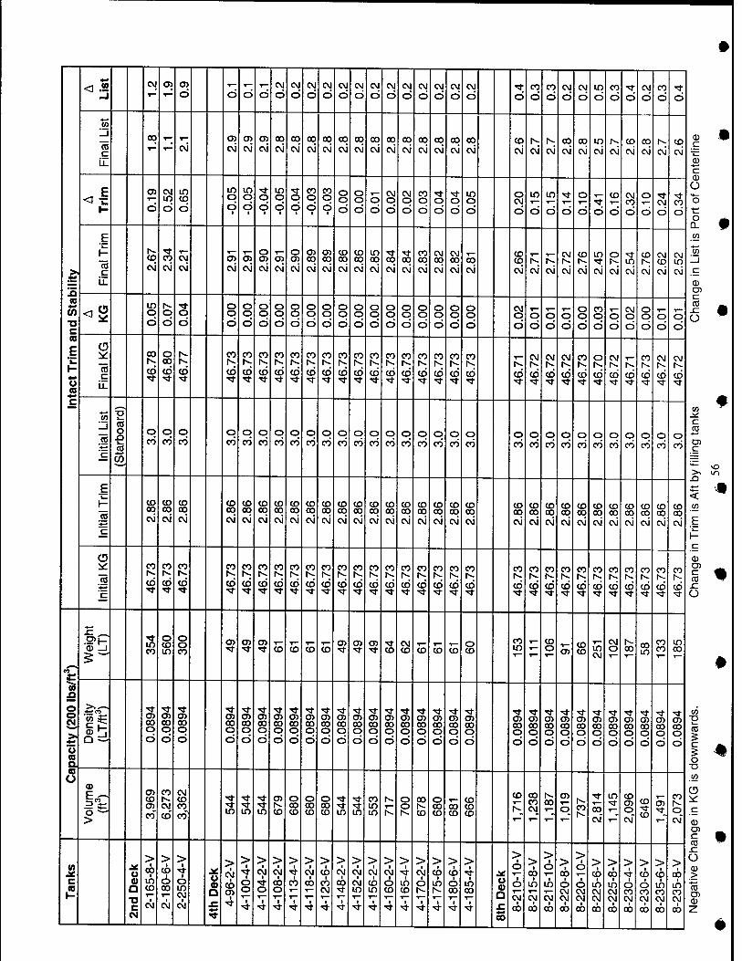
>
!D 2 (0 "O c a E k. 1- o m c
OJ a> d d d d
CVI
d CM
d CM
d CM
d CM
d CM
d CM
d CM
d CM
d CM
d CM
d CM
d CM
d d CO
d CO
d CM
d CVI
d in d
CO
d d CM
d CO d d
w LI
la c ii.
CO ^ CM
en cvi CM
en CM
oo cvi
00 CM
oo CM
00 CM
CO
cvi oo cvi
CO
cvi OO
cvi 00 c\i
00 cvi
00 cvi
oo cvi
00 CM
CO
CM cvi cvi oo cvi
00 cvi
in cvi cvi
CD
cvi 00 cvi cvi
CO
cvi
T—
d CM in d
in CD
d in o d
■
in o CD
§ d
1
in o d
1
O
d 1
CO o d
1
CO o d
1
o o d
o o d
o d d
CM o d
CO o d
o d d
in o d d
in
d in
d d
o
d 5 d
CD
d
CM CO
d
o
d
■5t CM d d
E H
LL
c\i CO
CM
CM
CM cvi CM
o
cvi CM
o
cvi 00 cvi
05 CO
cvi
CD 00 cvi
CD 00 cvi
in 00 cvi
s CM
00 cvi
CO oo cvi
CM 00 cvi
00 cvi
00 Cvi
CD CD
cvi cvi r>3 cvi
CM
CM
CD
cvi
in
cvi CM in Cvi
CD
cvi
CM CD
cvi
CM in cvi
<§ in o d d d
o o d
O O
d o o d
O O d
o o d
o o d
o o d
o o d
o o d
o o d
O O
d o o d
o o d
o o d
o o d
o o d d
o d
o d
1—
o d
o o d
CO o d
O d
CM o d
o o d
o d
T— o d
O
75 c
00 o 00 CO
1^ CD
CO
crJ
CO
CD
CO
CD
CO
CD
CO
cd •<*
CO N
CD
CO
CD
CO
CO
CO 1^
CD
CO N.
CO
CO
CD
CO
CD
CO
CD
CO
CO
CO
CD
?2 CO CD CO
cvi
cd
CM
cd •<*
CO
CD
o
cd
CM
cd cd
CO
cd ^1-
CM
cd
CVI
cd
CO I— a o
CO
O
CO
o CO
o CO
o CO
o CO
o CO
O
CO
o CO
O
CO
o CO
o CO
o CO
o CO
O
CO
o CO
o CO
o CO
o CO
o CO
o CO
o CO
o CO
o CO
O
CO
o CO
o CO
o CO
o CO
o CO
o CO
E
1- m
CO CD
c\i 56 00 c\i
CD oo CM
CO 00 CM
CD 00 cvi
CO 00 cvi
CD 00 CM'
CO 00 CM
5S 00 cvi
CD CO
cvi
CO 00 cvi
CD 00 cvi
CO 00 cvi
CD OO
cvi
CD 00 CM
CD CO
CM
CO 00 cvi
CD 00 cvi
CD OO
cvi
CO 00 cvi cvi
CD 00 cvi
CD CO
CVJ
CD CO
cvi
CO 00 cvi
CD CO
cvi
CD 00 Cvi
CD CO
cvi
CD 00 cvi
CD 00 Cvi
C«3
C£>
CO 1^
CO
CO 1^
CD
?2 CO
CO
cd
CO
CD -a-
CO
CD
CO
<D
CO 1^
cd
CO N.
CD
CO
CD XT
CO
CD
f2 CD
CO
CD
CO
CD •>*
CO 1^
CO 1^
CD
CO
CD ■<4-
CO
CD
CO
CD
CO
cd •>*
CO
cd •>*
CO CO
cd 'it
CO
cd
CO
cd
CO 1^
cd
CO
cd
CO
cd
CO
CD
XI
i o & CO O
o _l s in
o o CO ? T-
CO 5 s 5 en Oi 5 eg CD 5 5 5 o
CD
CO in
-
CO o 5) CO
CD LO CM
CM o oo 00
in CO CO
in 00
8^ d 00 o d
CJ> 00 o d
§ d
00 q o
00 O d
Oi 00 o d
§ d
00 o d
•<* CD 00 O d
CJ) 00 o d
§ d
oo o d
■<1-
00 o d
00 o d
■<3- 05 00 O d
§ d
en 00 o d
00 o d
oo o d
00 o d
CJ) 00 o d
■5J- CD 00 o d
§ d
en 00 o d
oo o d
CD 00 o d
§ d
00 o d
CD 00 o d
(D
o ^- >
CO Oi CO
CO
CM
co"
CM CD CO
co" in co o 00 CD
o 00 CO
o CO CO in in in
o 00
co CD 5 CO
CD CD CD
CD 00 CO CM_
00 q
■"t
00 CM"
in CD en o CM"
CD •<t CO
CO 1^ o CM"
c n 1-
■o c
CM
> 1
00 1
in CO
CM
> 1
CO 1 o 00
1 CM
>
1 o in
CM
9
>
CD o>
1
> 1
1 o o
1
> 1
o 1
> 1
CM 1
00 o T—
1
> 1
1 CO
1
> C<l
1 00
1
> CD
CO CM
4
> 1
CM 1
00
T— 1
> I
CM 1
CM in
> 1
CM 1
CD in
1
> 1
CO 1 o CD
1
> 1
in CO
4
> 1
CM 1
g 1
> 1
CD 1
> CD
1 O 00 T—
1
> 1
t in oo
4
^
£ s
> 1 o
1 o CM
1 oo
> 00
1 in
00
> 1 o
in
CM
00
> 1
oo 1 o CM CM
1 00
> 1 o
1 o CM CM
1 00
> CD
1 in eg CM
00
> op in CM CM
00
> 1
CD CO CM
1 00
> 1
CD 1
o CO CM
00
> CD
1 in CO CM
00
> op in CO cvi 00
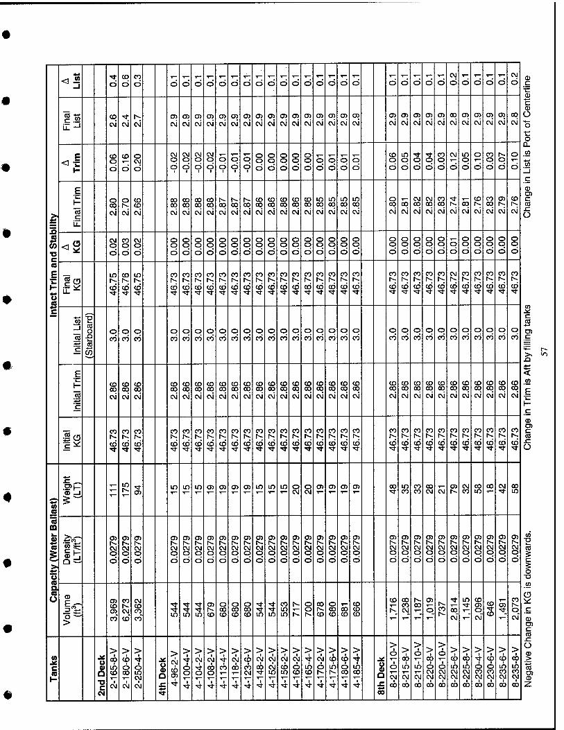
•
1 !5 CO
■o c (0
E 'iZ H
c
<S d CO
CD
CO
CD d d d d d T—
d d d d d d d T—
d d o T—
d d d d d d CM
d d d d d CM
d
13 CD
c\i CM CM
05 CM cvi CM
<y>
cvi cvi 05 cvi
en cvi cvi cvi
O) cvi
en CM cvi
en cvi cvi cvi
en cvj
en cvi
en cvi
<n cvi
en cvi
en cvj
00 cvi
en cvi
en cvi
en cvi
en e\i
00 cvi
CO o CD
CD
CD
o CM
d
CM O
d ■
d 1
d 1
CD o d
o <6
o d
1
8 d
o o d
o o d
o o d
o o d
o d
o d
o d
o d
CD o d d d d
CO o d
CM
d
in o d
o
d
CO o d
o d
o T—
d
E 1-
lo c
o 00 c\i
O CO CD
CM
00 00 cvi
00 00 cvi
oo 00 CM
00 00 c\i
00 cvi
So cvi cvi
CD 00 cvi
CO 00 cvi
CO 00 cvi
CD 00 cvi
CD 00 cvi
in 00 cvi
in 00 cvi
in 00 cvi
in 00 cvi
o 00 cvi
T— 00 cvi
1
CM OO
cvi
Si! oo cvi
CO 00 cvi
1^
cvi 00 CM
CO
CM"
CO 00 cvi
en
evi
CO
cvi
<« CM o CD
CO o CD d
o o d
o o d
O O
d
o o d
o o d
8 d
o o d
o o d
o o d
o o d
o o d
o o d
8 d
o o d
o o d
o o d
o o d
8 d
o o d
o o d
o o d
o d
o o d
o o d
o o d
o o d
8 d
Is CD
CD
in
(6 •>*
CO
CD
CO CO
CD
CO
d
CO
d
CO
d
CO
d
CO
d
CO CO CO CO
d
CO
d
CO r-- d
CO
d
CO
d
CO
d
CO
d
CO
d R ^
CO
d
CM
d
CO
d
CO
d
CO CO
d
CO
d
CO o € CO
o CO
o CO
o CO
o CO
o CO
o CO
o CO
o CO
o CO
o CO
o CO
o CO
o CO
o CO
o CO
o CO
o CO
o CO
o d
o d
o d
o d
o d
o d
o d
o d
o d
o d
o d
o d
E 1- CO
00 cvi
CD 00 cvi
CO 00 CM
CO 00 CM
CO 00 cvi
oo cvi
CD 00 cvi
CO 00 cvi
CO 00 cvi
CD 00 cvi
CD 00 cvi
CO 00 cvi cvi cvi cvi
CD 00 cvi
CD 00 cvi
CO 00 cvi
CD 00 cvi
CO 00 cvi cvi
oo cvi
CD 00 cvi
CO 00 cvi
CO 00 cvi
CO 00 cvi
CD oo cvi
CD
CM
CO 00 cvi cvi
CO CO
CD
CO N.
CD
CO
co
CO
CD
CO
d
CO CO CO
d
CO
d
CO
d
CO
d
CO
d
CO
d
CO 1^
d
CO CO 1^
CO CO
d
CO
d
CO
d
CO
d
CO
d
CO CO
4 CO CO
d
CO
d
CO
d
CO
d
CO
2 _. .2>|- 0) _1
- in in in in CD 05 O) en m in in S S en en <n cn 00 in CO
CO CO
00 CM CM ^ ?^ 00
m 00 CM 00
in
m lb.
i >
CO O
CM o CD
CM o CD d d d
CM O
d
t^ CM O
d
CM O
d
CM O
d d
CJ>
d d
o>
d d d
en
d d
CM o d
CM O
d
en
CM o d
en
CM o d
05
d
cn
d
en
d d
en
d
en
CVI o d
CM o d
CM O
d
en
CM o d
0) OJ CD o> co"
CO
CM
CD"
CM CO CO
co" 5 in
5 in
5 in CD
o oo CD
o 00 CO
o 00 CD in in in
o o
00
co
o 00 CD
00 CD
CD CD CD
CO 00 CO CM_
00
T—
en
CM"
in CD en o CM"
CD 'Si- CO
■5t
CO
o CM"
i2 c
|2 O 0) Q •o c
CM
> 1
GO 1
CO T—
t CM
> 1
CD 1
o 00
1 CM
> t o in CM
CM
^
£ ^
>
CD
1
> t
o o
1
> ■
CM
s 4
> 1
CM
00 O
4
>
CO
■r- 1
> 1
OJ 1
00
1
> CD
1 CO CM
■
> CM
1 OO
1 ■5t
> 1
CVI 1
CM in
1
> 1
CM 1
CO LO T-
t
> CM
t O CO
1
> 1
•>* in CD
1
> 1
CM 1
O
4
> 1
CO 1
in
1
> 1
CD CD 00
1
> 1
in 00
1
o
Q sz 00
> 1
o 1
o CM
1 00
> 00
1 in
CM 1
00
> CD
1 in
cvj 1
oo
> 1
00 1 o CM CM
1 00
> CD
1 O CM CM
00
> 1
CD 1
in CM CM
1 00
> I
00 in CM CM
00
> 1
d CO CVI
00
> 1
CD
d CO
00
> 1
CD 1
in CO CM
1 00
> ob
1 m CO CM
00

Appendix B: Preliminary POSSE Modeling Results
Provided by Norfolk Naval Shipyard Structural Engineering and Planning Office (Code 256)
58
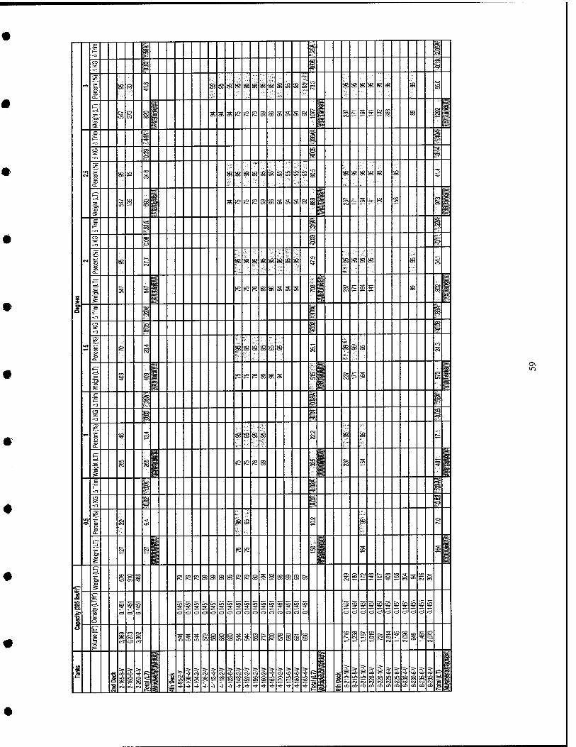
•
■<1 IF 1 <^ en
I— "^ — » O
-3 n <;? « s*;
eo 1 a.
s s CO
5 s? S3 S3 S3 S3 S3 S3 S3 S3 S3 s S3 S @ S3 S3 S3 S3 S3 s
i=r % § S
^ s S a r2 lO S S S s a a S
^ ?^ S H §
" s ^i
1^ i ,g
i ^
_-- — — — — "~ ~~
CM
Q_
s u2 i g? S S3 S5 « S3 S3 S3 s s? s fe te ft S3 S3 S3
§ g 8 s LO LO CO 83 S a a a ai 8 S i^ S ^ S S si T
1 -< s s,;
1 5 ^"
CM 1 s c\i « S3 S3 S S3 S3 S3 S3 « S3 s S3 S3 S
■ P^ (1
■
^ s S K K f£ 83 S a a a g a r;^ s 5 S g^
1 i N 7. 1 1— S s i -CI
<1
g o 1 <?
s«
i2 i e
■^
^ S S? S3 S3 S3 SJ s S5 S3 S3 CO
i ON
5" s § to kO e 83 S a S ^ S
LO !_■ -i 1— S § 1 <d
-C3
s 1 1 f^
^, ? S3 S3 s? S3 si 83 « r^
S s g rG K s 83 ^ g s f 1 5: ■■■»
_ 1— 4 1? i !s;^-
5? P s S -^ ^ o IS ^
s cx
Si CO s S s ^ CD
'"
^ ^ -■ s e s i S
^ m,
¥ S to 55 i s s ff s? 83 S3 s; ej> S s S S s S3 S3 fe f s K f & CO S 5 a CO
c3 §
~" ~~ __ "■"
dU § P! s? s? IS s? !S Lr> s? S? « ss s? !S s « SS !S s iS « S 9 « i5 S !S * !§ !g § ir>
^ 1 <= <= o <=> o <=> C3 CJ> O CJ o o o e=> C=> •—' '-' •-J '-'
* i C-J
CO
CO ^" 5 S S CO i i i S 5 a S s s § i s JE s g i S CM
g i CO § 1-
^ 3a
J2 1 -» ~3- •>• -s- ■> ":» ■> ■s- ■> ■> ■> ■=» > > > tJ S ^> S >• ■i > > > > > > a ^e rf. ,f^ F=- ^ s <iS CM rii -r ^ c6 =6 ^^r CD CO CO t; i-i; & s s ^ ^ s s s * ^ SS ? K ik s g g i 5
■a i ^ g § g s S •B
M cil A CsJ iS i -i -t ^ -s- -i- -3- -a- -a- ^ "^ ^ ^ '»" «j- "=^ ^ fi i oo oo e
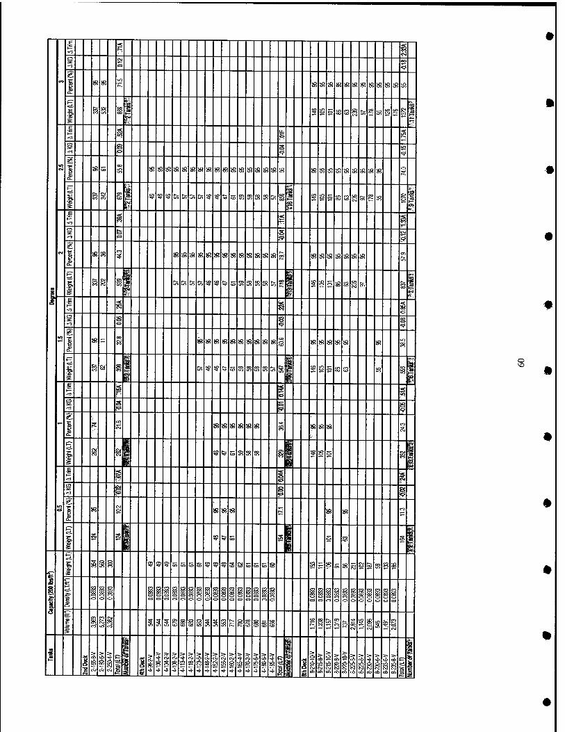
«o
cC 5^ "OJ cc
5 ^
»3 s '^ S3 3! S3 33 33 33 S3 « 33 33 33 s;
^ _ _ ^
S S S i
1 f ° 5 S s 8 &> CO ir> S
to g •TT^
t— § ^ 5 5
8 1 10
5 g. j s CO
CO
S3 s s? S3 s S3 S3 S! S3 S3 S3 « S3 S3 33 8! S3 ffi S3 S3 S3 S3 S3 33 33 S3 s jj;
1 . CM g 1 ig Sg to lO te K ft ^ sg ^ s CT> S S S Ci
i to
S 5 g S g & " !8 g C7>
> i < s 1 s CM
5 &
CM
1 » 85 5 i$3 S3 « S3 S3 S3 S3 S3 S? S3 % S! S3 R s; 5! s; 3! 33 S! 3! 10
s 1 g « i
^i;~
lO tjfj LfJ S Sg to ^ <B ffi ffi S S to CO to S 2 S S 8 fe g 1
ts
^ N czi
^ -^ s 1 £.
iS " CO
Si 83 S3 S3 83 S3 83 83 83 83 83 to
s S3 83 83 83 S3 S?
s t g a g ■r> ^ ^ is s S3 S OO S te s f S 5 S S !8 S 1 * ■o F ^ -n i i al "~ ~"
1 S: C\j ^ S3 S3 S S3 83 ;i S3 83 83 CO
1 g ^i i? !5 s S3 S ffi ^i f S 5 ^ 1 g
s
t— s 'd '$
1 P s ^ !B
CO
S3 S! 83 83 83 ^
1 S -R i? ' CO ^R 5 S s 1
1
5. S S B ? s <7i S s S !H ? 5 S s a to CO CO S a := s 5 S K S & S B S
1 § <=>
s? g C3 c> c> C3 i i § a o ci d c=i § <=> d <=i ci tzi CJ i <=> ci 0 d c> 0 i C=i
?=. *~" "" — —
1 CO- U3 S S 5 s tC5 § § § S 5 S r^ ^ i s i to 1 fe 2?
0 S trsT
s s i S- 1
|2
1 5 e ^
2 i 1 >
-3-
>
5
>- s
> 3!
5 1 5
^ s 5 > >
cvj
5 1 -5-
1 >
i 5 5
>•
5
=>
5 1 1 1 5 1 S
S > c6
i c6
> >•
cf>
> > > t& i ci
i2
^^
o
•
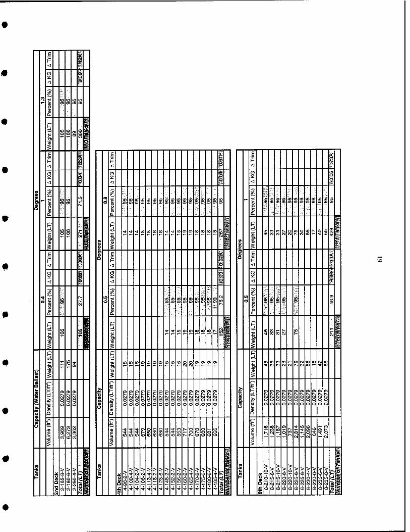
E 1- i < O Y < ^^ SS! ■
m c in in in in ^ o> t» a> 0) <) a> Q.
i H iw _I
in (D CO
o S o (0 s: a m o rf § R 1 < (T M
^ < P
H! ss
1 o> g in
k H i% _l
in <0 ^ 1^ o <0 N
t: o ^^^M o -;. ^^ 5 '' H E K- < (0 i^ <
s« *
g I^
o c <s f5 <9 Q.
1 H ' MgH LJ in in IS o a ''' 'RH m 'f:' BS^ 5 m "■' ^..^ 1-
1
IT j; lii c» m o
i g n jT-^
m ^ H; O) O) n>
N N CO Al <\1 ^ ji- o o o
CO o o o > c
u n n n 5
ffi E
O)
CO
CNJ
CO
CM
CO
10 1 c o
> > > jjiif;
Jr: 00 <0 ■* K ^ H iij uS c^ o H Ip
n to eo in
1 CM
(M C\I CM S h. ^
■M ^ E
^ ^ ^ ^ ^ ^ ^ ~ ~ ^ ~ "" ~ E V H n H P < B <
i ^ s <I 9 < _^^ ,-^ n^ S^
■^ in in in in in in in in in in in in in in in in in t- c in in m in in in in in m in in in o H) o> o> ts CJ> a> O) o> CJ> O) (j> 0) (3) <y> en OJ at o> c»
p £J n> o Q. Q.
~ ~ ^ $M P ^ P l^
-J, ■* ■* ^ 00 CO CO CO ■* ■* m 0) a> 00 oo oo CO
^ f E in CO
CO m CM o CM
in g s t-- §
in in S •*
m
1 '(1)
5 1 10
1 O)
5 i E ^
E 1 1- 1- 1 < b <
? o o s i < ° <1 § ^^ ^-^ S« S«
in in m in m in m in m o CM lO c In in in m in
at
o (ii a> 0) a> O) a> O) o> at ()> [^
O) o> p y
O Q. Q.
^ ■" '" ^j w P fe' p 1 n 2
-* ■* in 0) 05 CO oo 00 1^ a 1 '(1)
in CO CO CO CM
in CM
i 5 ^ ^ P P Hi *- in in in n> CD m O) in in in o o m O) O) m E c»
eo in CO 00 1— at CM CO 00 CM 00
o> T- CM CM T- ■* CO CO OJ CM N ■^
<ii <D
a-
g
2-
5
1 o> m m m Ol n> n> m at m CD m o> oi i at 05 o> a> 0) at at 01 0) 0) 1^ h- h. r^ h- [^ rs. l~. N t^ 1^ f~ r^ h- (> r^ r^ t^ h- 1^ t^ r-- N N
ffl (M (M Al N IM Kr Ki Ki KI (M <M (M rvi <N in ^ CM CM n jS- o O o o O o o o o o o o O O o O a. O O o o o o P. in o o o r> O o o o o o o o O O o O a (/} O O o o o o o o o O o U O o
Q _^^ ^ ^ ■" ..-^ h h
(n t~- at ■* in <n CO •* ■<t ■* 0) ■* (O r^ o OO C3 CO <D on ■* Ol (7) r~- E 3
■» <t ■» N Tt in o h- CO CO CO E 3
N o on C5 if, ■* o 10 in in (D (1) lO IV U) in in r~- h- CO (D (O CO ^'' T-" CM" T-" CM OJ
O o > >
fi ■ 1-^
lit ff (0 >. ^ ~> * c a J£ > :> >
CM
> CM
> > CM 5 >
CM
> CM
> CM
> > 4
> CM
> (6 ^ 5 P fe c ra je
O > CO
o > 00
o > <o %
> 4 5 1 ; P 1 H o n Tt no CO oo <A rfl CM (0 o in O in o m pJ ify 1-
S 6 in in o o m in o o in in ^
."i o o o CNI Tt in in en en r~. r- m CO "^ ''1 "'. U c» 1— T- fS 'jS CM CM CM CM CM CM CM CM CM CM IM f» ^ £ ■Tt ^ Tt Tf Tf ■^ -^ Tf rt Tt Tf fl- ■<t ■fl- •<t ■* n ta £ 00 CO oo oo oo 00 00 CO CO CO CO o •a s P s s K. i
Appendix C: Preliminary Cost Estimation Data and Worksheets
62
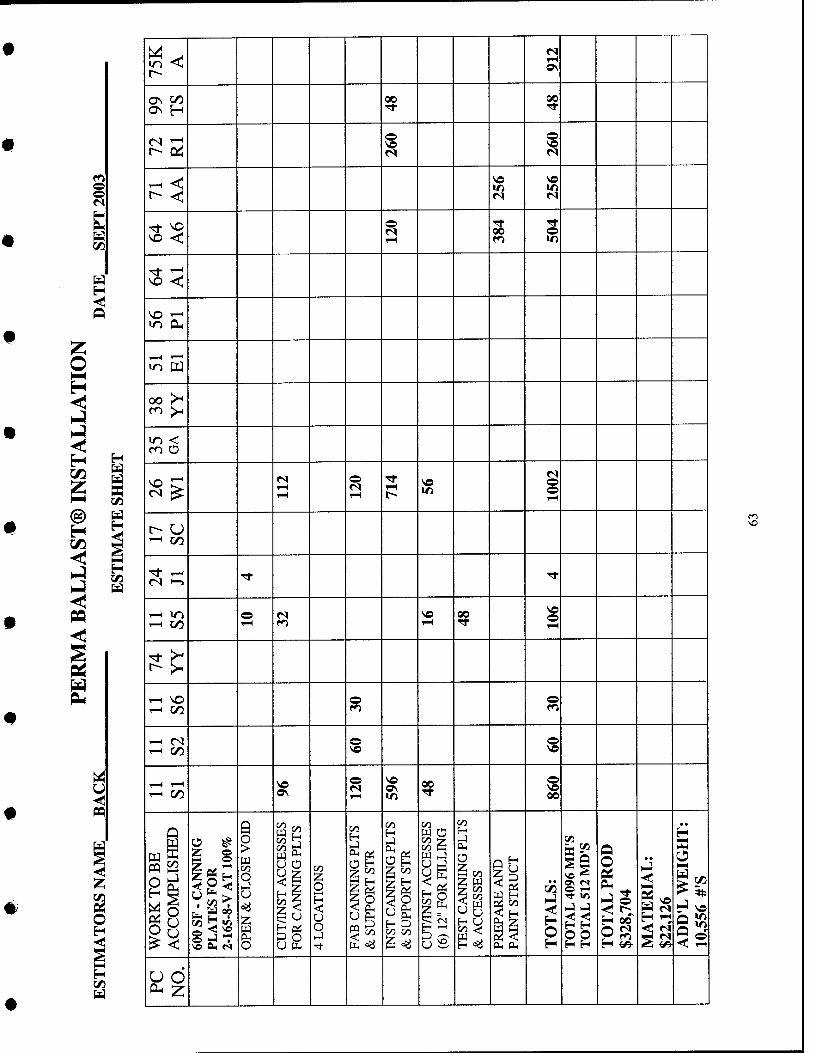
o o
Q
H
H
H
n
ON OC)
^ < ^ <
•n W
oo >^ en >H
T-H in ^ C/5
C/3
^ CO T-( CO
oo
OH ^
b* o o > o 1-1 01 H O -si H4
> U ■
00 =a ■o z ve w r-^ CL, f^ o
fs
OS
00
O
U o
o
o
e
o
00
fe '^
00
o
o
ON IT)
«o
en 'z
f-' o
B §
QO
<=«
00
00
o
o IT)
o o
r*^
«
o 00
H o
o o
<
o
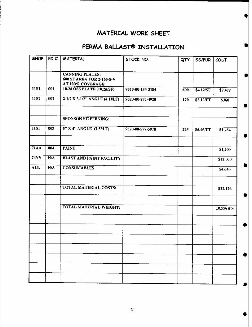
MATERIAL WORK SHEET
PERMA BALLAST® INSTALLATION
SHOP PC# MATERIAL STOCK NO. QTY SS/PUR COST
CANNING PLATES: 600 SF AREA FOR 2-165-8-V AT 100% COVERAGE
llSl 001 10.2# OSS PLATE (10.2#/SF) 9515-00-153-3184 600 $4.12/SF $2,472
llSl 002 2-1/2 X 2-1/2" ANGLE (4.1#LF) 9520-00-277-4920 170 $2.12/FT $360
SPONSON STIFFENING:
llSl 003 5" X 4" ANGLE (7.5#LF) 9520-00-277-5978 225 $6.46/FT $1,454
71AA 004 PAINT $1,200
74YY N/A BLAST AND PAINT FACILITY $12,000
ALL N/A CONSUMABLES $4,640
TOTAL MATERIAL COSTS: $22,126
TOTAL MATERIAL WEIGHT: 10,556 #'S
64
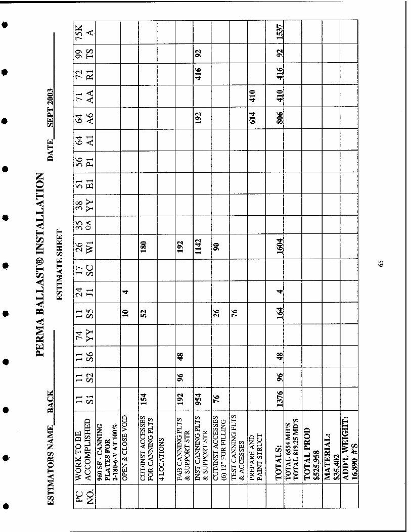
o o
t/5
H
«n < 1-H
ON H ^ 0\
1—1 i-(
© iH ■Tf
o 1—(
S? as 1—1 o 00
\0 '—' m OH
in W
oo >-' CO ^
to < en O
1—1 1—1 1—( 1—1
o ON
1-H
^ CO
^;::: Tt ■«*
^ C/3 o 1—( s ^ 1-^
-—I C/3 oo 00
r-H (N ^ CO ^ ^
1-H r-H '—• CO 1-H
^ ^ 1—1
WO
RK
TO
BE
AC
CO
MPL
ISH
ED
96
0 SF
■ C
AN
NIN
G
PL
AT
ES
FO
R
2-18
0-6-
V A
T 1
00%
9 o > w 00
§ 00 ^
§ U
o
U o
00
OH
g (Si Is
00
ii 00 00
CU
T/I
NST
AC
CE
SSE
S (6
) 12
" FO
R F
ILL
ING
00
O
Is z ^ |w H U c/2 <; W
P 2 00 3 O H T
OT
AL
655
4 M
H'S
T
OT
AL
819
.25
MD
'S
o • •
2 H ^.
AD
D'L
WE
IGH
T:
16.8
90 #
'S
^§
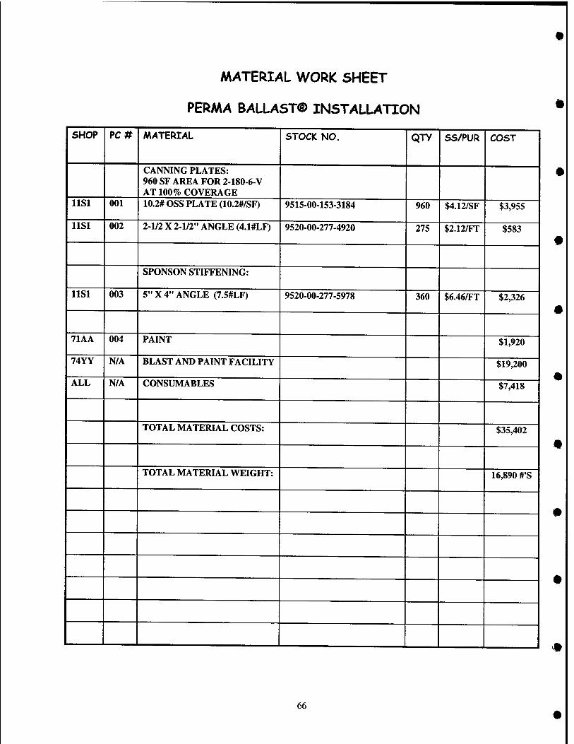
MATERIAL WORK SHEET
PERAAA BALLAST® INSTALLATION
SHOP PC# MATERIAL STOCK NO. Qjy SS/PUR COST
CANNING PLATES: 960 SF AREA FOR 2-180-6-V AT 100% COVERAGE
llSl 001 10.2# OSS PLATE (10.2#/SF) 9515-00-153-3184 960 $4.12/SF $3,955
llSl 002 2-1/2 X 2-1/2" ANGLE (4.1#LF) 9520-00-277-4920 275 $2.12/FT $583
SPONSON STIFFENING:
llSl 003 5" X 4" ANGLE (7.5#LF) 9520-00-277-5978 360 $6.46/FT $2,326
71AA 004 PAINT $1,920
74YY N/A BLAST AND PAINT FACILITY $19,200
ALL N/A CONSUMABLES $7,418
TOTAL MATERIAL COSTS: $35,402
TOTAL MATERIAL WEIGHT: 16,890 #'S
66
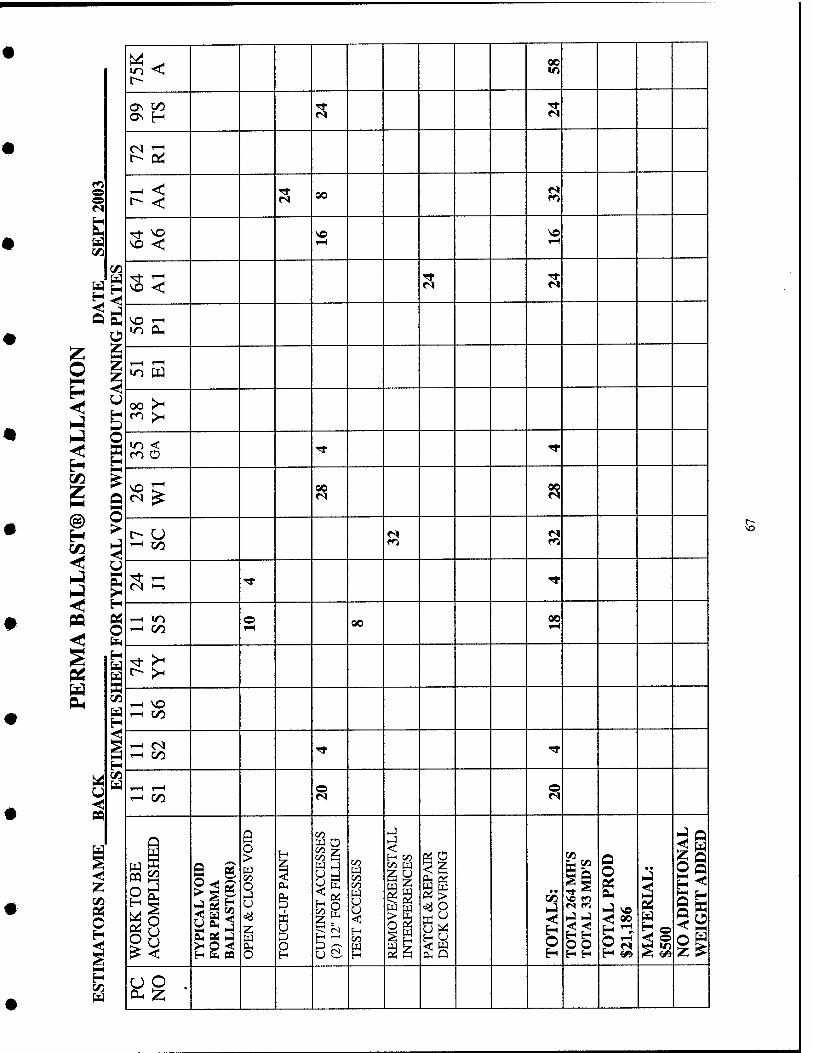
o o
OS O
^ I
o B H
@ g
H
n
in -^J r--
00
OS H ■* ri
F^^ ^ oo <*5
s:§ so 1-H 1—1
S5 ^ ^
»n pLi
,—1 r-H
oo >^
•n < m O ■* TT
QO ?5
Tt Tf
^ »n © QO 00 1-^
r^ 00 rr Tt
1—1 I—1 ^ S
WO
RK
TO
BE
AC
CO
MPL
ISH
ED
TY
PIC
AL
VO
ID
FO
R P
ER
MA
B
AL
LA
ST(R
)(R
)
a o >
u
8
1 1 C
UT
/IN
ST A
CC
ESS
ES
(2)
12"
FOR
FIL
LIN
G
00 W 00 00
8 u < 00 W H
H 00
=y o
H u < w OH P
• •
s
TO
TA
L 2
64 M
H'S
T
OT
AL
33
MD
'S
TO
TA
L P
RO
D
$21,
186
MA
TE
RIA
L:
$500
N
O A
DD
ITIO
NA
L
WE
IGH
T A
DD
ED
<^9 • c^ :z;
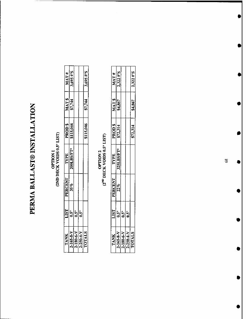
* c« 05
H * * < Ss' 0\ S
^ rt 5 <
rr t^ t--
^
w VO « Q
■* rr o o
O «n Vt 06
P- u ^ eu ^ >< 09 H o o
H Z
« r'j u BU
H o n o V) IT) W ID
O O o
> > > C/) iii I
00 ■ 4 NJ
< 58 o 00 ,?
H f-t rH fS p M <^ r« H
o
OH
Obii u
* 1/1 CO
H * % ^ S
<» r-- 1^ VO VO 00 00
s
^ •^ rt
o t- r^
PLI ^ <»
U i»< CLi ^ >" *^ H
H Z
« r^ Ed pL,
H o n o (/) Ml U1 «n >-] o © ©
> > > CO ^ 00 sh ■ _]
s ■ O 00
© </1 ?
H 1-^ 1^ r^ O <s <s «s H
oo VO
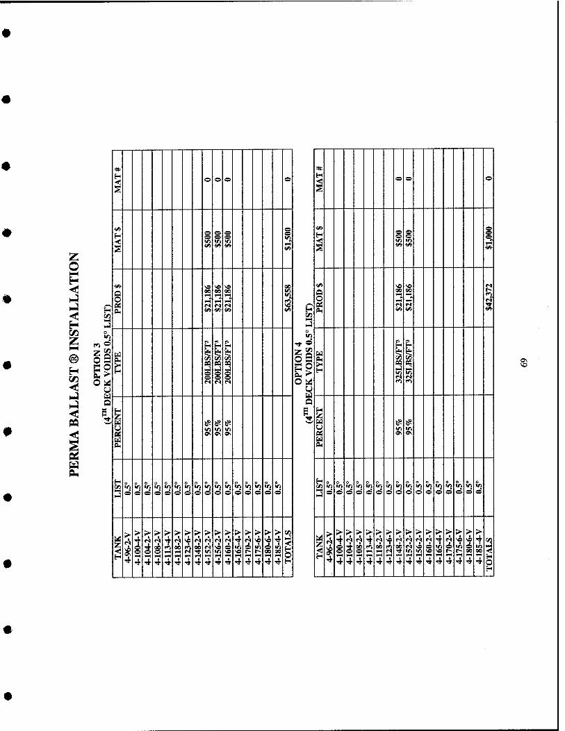
=» * o o o o o o o
§ §
, , s s s g
< S
>n in •<1 l/J in 1H •6» •Sfi- <«■ ««• •^ §
<«•
tf> V) V5 ve 00 ■^ <« « r^
§ 00
1-H
00 00 1—1
9 00
1-H"
00
—4 s nrt «S «S <s \o p£ r:* fi* ■^
H Oi *» «« m <«• H P^ <^ <^ •1/*
1/3 W3
M) 0 o
1/1 r) o p rt
f^ ^o w p
O S g ^ 1 1 1
§9
o ^ M r<l fS Obd r<^ 1*1
u U
Q
i u «^ !^ ?s I # # u >/) >n tn «n in pj OS ON ON PS o\ o\ u E^ bl PL,
H H o o o o o o o o o o o o o o 0 o »i m tn >n trt «o V) m u> V) V) in in <n V) m m CA in m m m m «n in in in in m V) m V» Vi "f 1^
o o o o o O o © o o e o e o o o 3 o o o o o o o o o o » o o e O e
> > > > > >■ > > > >• > > > > > >■ «J > > > > ;> > > > >■ > S> >- > >- > >
2; 4 •? ^ 4 f»1
r!| ve r< •? M <s i f<« ve ^ 4 (*j ^ ^ f? <V ? <? ve A «s «s *? 4 «? Ne ^ 4 2 i A 4 rr on 1*1 an r!» NO o in e m o m ^ ^ o 4 00 rh 00 1*1 00 <s « 9 ffi p !^ o «n
■< o o o »H «s •^ ifl V) NO « r~ r-- 90 00 o e e 1-4 f«H f*^ Tt m m « 5 r- r- 00 00 <! H 1-1 ^H ^H TH 1H ^ rt <-( 1-1 1H 1-H 1-H fH iH 1—1 H IH rl TH H
■* 4 4 ■* TT ^ ^ 4 4 4 4 4 4 •* TT •* H •* 4 4 4 4 4 4 ■* ■* 4 ^ ^ 4 4 4 4 o
0\
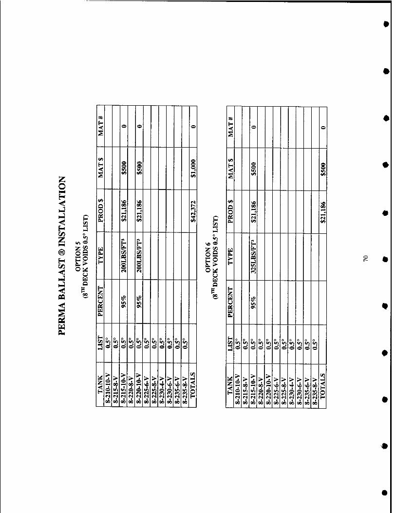
I/)
o
O c« a o >
u u Q
© o ©
1 o o r-T
Q O
00 00 1—1
eu (/I pa
i
u (A
^ ^
^ ^
!3 0
o o
2 0 V) d
0
©
o in d
o
©
o
2 o
c5
0
©
o 1/1 d
o 1/1 d
z > • o f-H • o
00
> •
I 00
> 6
■
n
> ■
00 ©
2
> 6 1-1
©
I 00
>
I 00
> 1
00
> 1
I 00
> 1
2 1
I 00
>
1 00
2 1
H 1/3
©
o9
u
00
*
© o
o ©
O 00
1-H
00 1-H 1-H
eu H
IT)
Z a u eu
^ S
2 0
©
o
©
o VI ©
o V) ©
o
©
o in ©
o
©
o
©
0 V) ©
o v> ©
o V) ©
z > o
1 00
> ■
00 1
r« o&
> • © 1-H
1 tn I-H
■ 00
> ■
© M
I 00
> © 1-H
■ ©
• 00
> ■
'^ 00
> • 00
1 V)
00
> •
I 00
> t
©
I 00
> ■
V)
1 00
> ■
00 ■
1 00
H O H
o
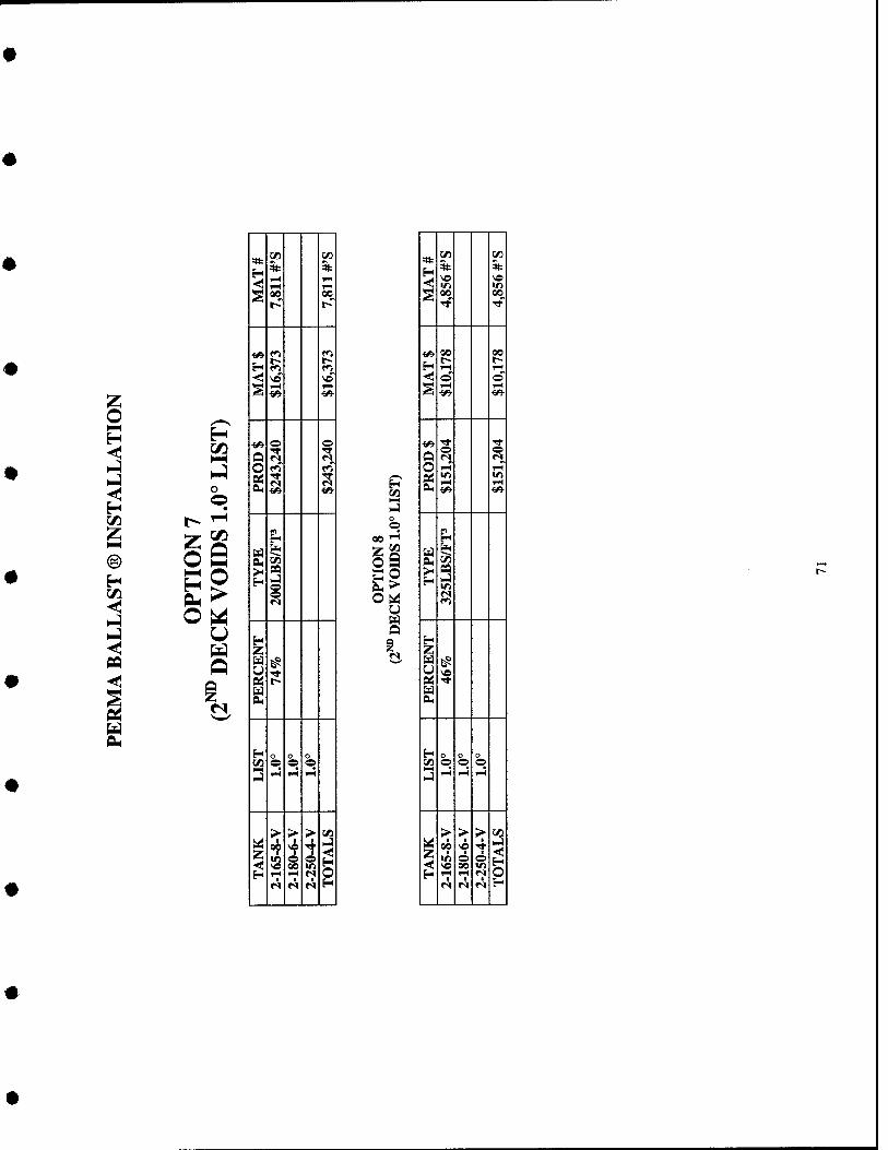
o H O
H C/3
o O
C/3
hH
O
r/i V)
H % * <! 1—1
l-H 1-1
S 00 00
^ P H fi f^
VC se
^
1H
^ o ^ U ri r« o ro r^
g CU ^ ^ ^
H M 1$ PU( ^
S 1
H Z
^ ^
OS ?• u OH
H o C/l o o O
iJ l-H i-i IH
> >■ > M
Z 4 o 00
o i-l
o H iH I-H n r^ «S M H
H W5
00 " >- CO
r/) 5/1 •V
ft ft IT)
S 00 00
<«■ 00 t--
00
H TH 1—1
< o o S l-H
■6» 1—1
i» s o U «s «s o iH r-i
g 1-1 1—( ^ ^5-
-H
Ed 'f 0. 05
s IT)
H Z
0« § M PU
H C/l o o o 3 iH rH 1—(
> > > IZl
z ■
o 00
4 o in o H iH iM n
fS ri <s H
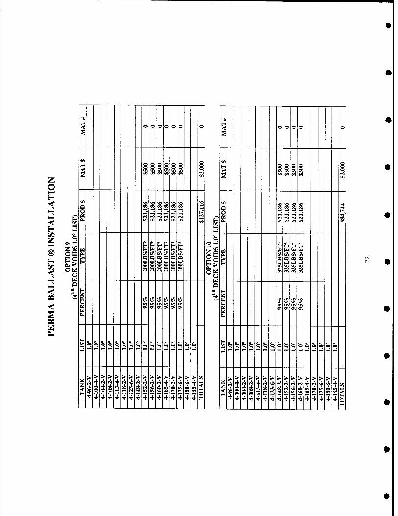
< *
e e o © o o o H o o o O o
S S
•0 1/1 V) IT)
e o in o
■6»
H s i O o o
S •!/3- <« <« «« <« <A '^ ^
^ «» <S v>
1 NO 00 00 00 00
P 1 00 00 00 00 5
4" 00
.^ 2 o O
o O
oa n ^ ^ p «
F © rH p P p p- Pu § lyj C/3 C/) ^ o S ^ f/^ T s oa pa s pa
o
S3
o o pa BS s s
u " S o <s
o o O ^ o
r»1
u _^ ___ Q ~
i # ^ ^ # ^ ^ 3,
(^ fS f^ f^ ^ 0\ ^ ^ ^ s % ^ S s
PL,
o o O
0 O
o O b b o
O o O
0 o h, b b 0 o 0 o O
0 O
O O h o
o O
O O
o O b b O
O 0 O
o e
o O b b o
O o e
kJ ^H ^H rH 1-^ 1-H i-( VH f-l 1-H 1—) 1-H rt 1-^ >4 T-H i-H 1-^ ^H w^ w4 ^ TM 1-^ ^H 1-H 1-H
z > > > > > >
^ > > > > > > > > > 2
i > > > > > > > > > > > > > > > >
'i- ^ ^ 'i' T 'J f^ '^ 2 4
«s -r <s VO ^ T 1 r^l 4 rJi M i »s >e «s fJ. f!i ri •<» «s v0 VO 4 r/1
4 00 o
4
90
4 i !2
1-H 1M
o 00
in 00 * o s
T-4
00
^H ?
1—, 1-H
e vo
1-H 1-H 1^
o 00 00 -<
■^ ■* 4 4 rt 4 4 ■^ •^ 4 4 4 H ■* 4 4 ■^ ^ 4 4 4 ■* •<T ■>* ■V 4 4 ■<» •* , — _ H
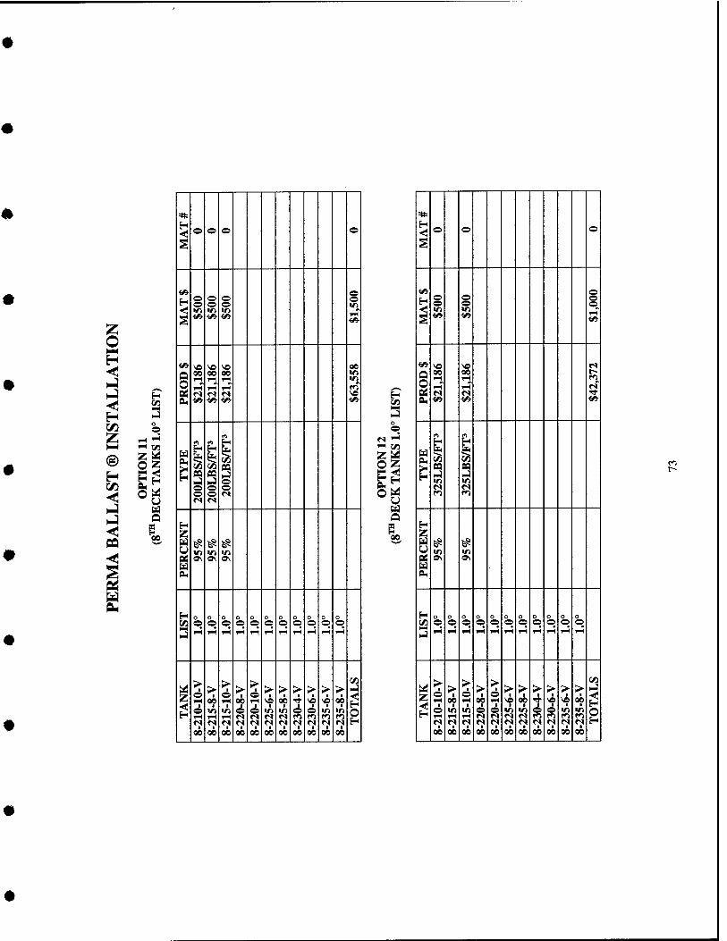
H
o H
o
t/3
% H o o o ©
s
i^ © H o o o o o © © ■n ^^ V) >r> VI
^
<^ i^ <^ ^
^ ve \e ve 00
a 00 00 00 ir> 1—1 iH T-l W)
y 1—1 1-1 tH f^ p< r« «s »s ve s f» <^ <^ <^
rt rt
^ H ̂
^ ^
t 99 i
(/5
pa
i CQ
i ^ z ^ ̂ ̂ in «n VI fi^ o\ o\ o\
w eu
H o o o o o
1^ o o o © © © © o © © © 'J 1^ iH 1-1 i-< I-( 1-1 TH 1—1 1-1 1—( i-(
1-1
>- > © S^ > o
rH
> > > > > >- 2 O
*? *? ve 00 ■>* ve SB 00 o W1 Ul © © v> Irt ^ s V) V) rH tH >H IN »S «N «N fi r^ fT) (*5 <s n r« (S r« r* n fM ri <v m 00 00 00 00 00 00 00 00 00 00 00
1-1
z o H P^ o
H IZ) h-1 >-) o © 1-5 CO US z <! H
00.
*
< © © o
© ©
© © in o
1-5" «5-
Q O 0M
ve 00 rH IH"
1^ iH iH
M
fn. ^ ^
H Z u pj
^ ^ in
0\
IH
o © IH
o © IH
o © iH
o © IH
0 © rH
o © iH
0 © iH
o © 1-5
o © 1-5
o © 1-5
z © IH 1 © IH
*? 00
> oi)
■
iH
00
> © iH
in iH
> 00
00
> iH
i 00
>
00
> 00
00
>
00
> ve
00
>
in
■ 00
>
in
■ 00
2
1
m r-
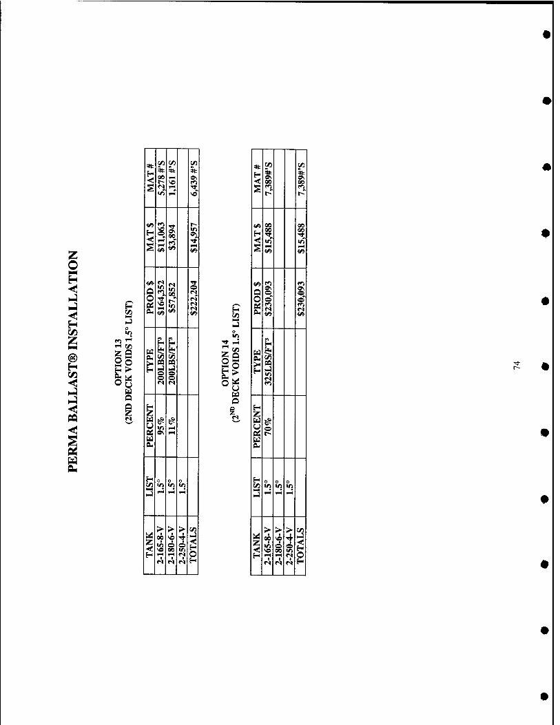
H 1/3
& fad
o
r<
00
W3
SO
00
0 IT) 00
g ^
0 i H Z u u
1^
0 0
"1 rH
0
1^
z ;2
■ 00
1
1—( 1
> ■
i •
>
0
2
irt
£:^ U Ed a «s
4t c« c« H ^ ^ ■< 00 00
S f^ n r- t^
</* 00 00
00 00 H TT rr
<; V) «rt S
^ Si s C) 0 0 0 0 ©~
§s fo s
0
u ^ S M >< pa H
i^ ;z
0 0£ r- u eu
H 0 0 0 C/5 tn >ri IT)
>-) i-H <-i w^
> > > t/) ^ ■
00 « •4 NJ
Z <
• 6 00 ^ ^
H f^ rt n 0 «s M r< H
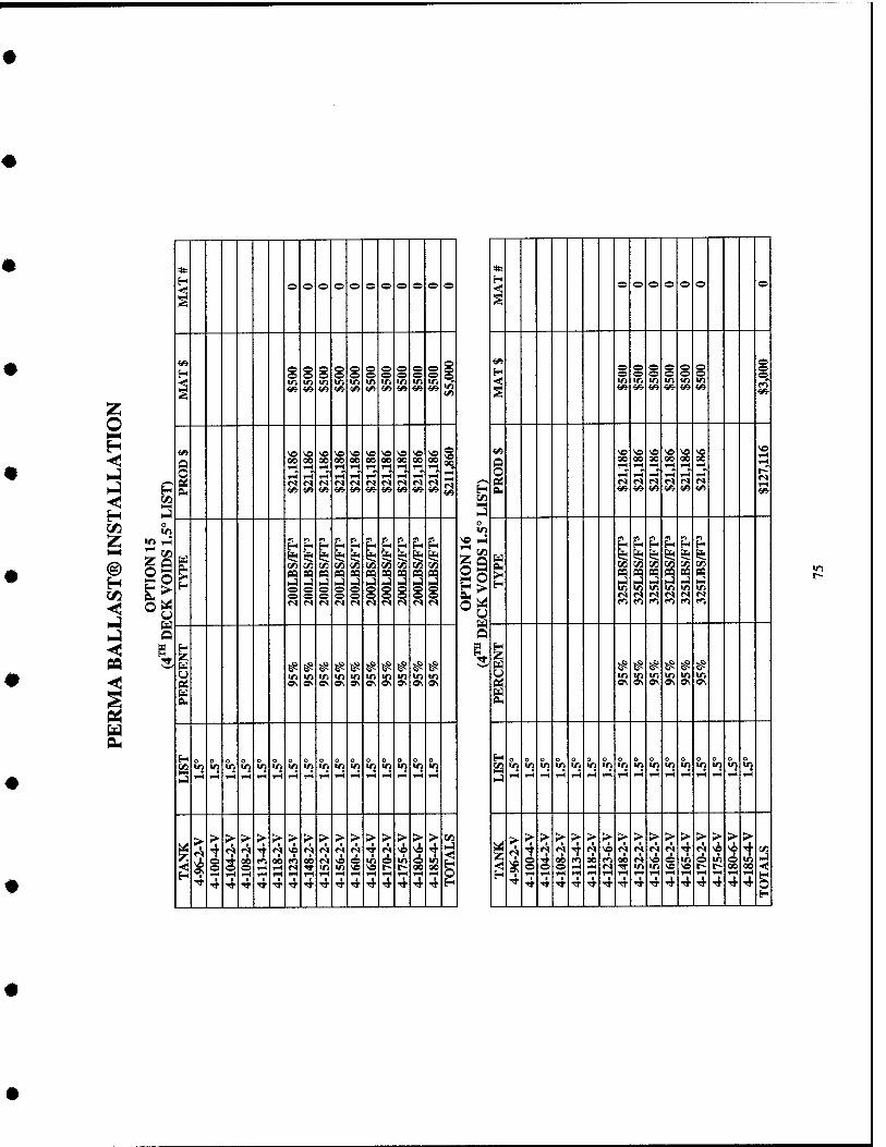
H 1/1
* * H
o o o o o o o o o e o o O o o o o o
§
^ o o o o ^ s § s s ^ g s
§ § « ^ o o o o
g
^
■n ■n in m >n w "^' *(* 8 ^■ ^• <» ^■ ^ m ^ iA «» i«- <^ <^ tfi •I/5- ■t/i- «* **i
i» ^ ^ ^0 ^ '« ve ve ve « ve 1 Vi VO >o v« ^O NO 1? NO
Q OQ 90 90 so 00 00 90 s oc 00 o 00 90 uo TH 1-1 1-1 n
Q 1-1 1-1
^ 1H 1—1 i-H rH 1-1 1-1 ?; m «S »s (S r1 fs r» »s <s fS M f^ «s (S M n M fS PN •W- ■s«- ^- ^^ •^ ^ f^ ^ m- •^ H
1—1
PM Vi <«• <»
o U^
PH f^ H « m
PH m LL P. PH
yl m yi « p4 PH
H
r^ r^ ^ in r^ is S u<
^ ^ ^ ^ n PS P3 pa PS pa pa pa pa pa pa pa PO PQ pa pa S " NJ " I-) N3 NJ hj I-) i-i hJ i-i >-J i-J [J H^ h-; 1-4
o o e o e m m m "i "i "i o o e o (^ »^ 1^ © o e J^" J^* r" £:< ?< n n c^ fS fs «s r< <M (S <s n o ^ f^ fO fO fi f> <*)
^ I H
U ^ 5? # # # # ^ # ^ ^ # ^ # ^ # # u *n >r> •D ID ■n ir> ■n ■r) >n >n m m in in in m e< OS ON o^ 9\ o\ o\ »v ON o\ o\ c« 0\ *v »> o> o\ ON
u 5?) eu Pi
H n o o o n H O O o o O 0 o o o o o o o o o o c« m V) iTi m IT) «n V) tn 1/1 tn V, m «n 1/1 VI IT) c« •^ "i VI in IT) in m m m «n "i "i ".' NJ i-H ^H 1-H t-H f-l TH 1—( p-4 1—( FH 1-1 rl i-( rH w^ 1-1 »J i-i ^H 1—f 1-1 ^H 1—t 1-1 1-1 FH 1-1 1-( ,H F-1 1-5 TH 1-5
> r-1
> > sr > >■ > >■ ;> > > >• >• > > >■
o
>■ > > > > S> > > > >■ >■ > > > > >
^ ^ •? ^ 4 N VO c!| <s «s *? 4 r^ vi ^e ^ (* n 1* <s <? T f? ve ^ rji <S| <S i r» ve NO ^ 1 ^ 'Jj
f^ -4 rri rA no f) on <s Vfl e m o in ^ in ^ ^ o 4 00 fo 00 fi 90 «^ VO o •2 p !^ o m ^
=^ ^»1 o o <s Tt in >n ve « t- r~ 00 00 o o o FH —H fs TT in in NO NO t^ t^ 90 90
H TH TH ^H 1—1 TH w^ r-( 1-1 T-* IH 1-1 IH iH rH H 1—t 1^ H TT 4 4 "* Tt ■^ 4 4 4 4 4 4 4 1- ■* 'sr H ^ Tt TT TT TT ■* ■<* ■* TT 1* 4 4 4 4 4 4 o
r--
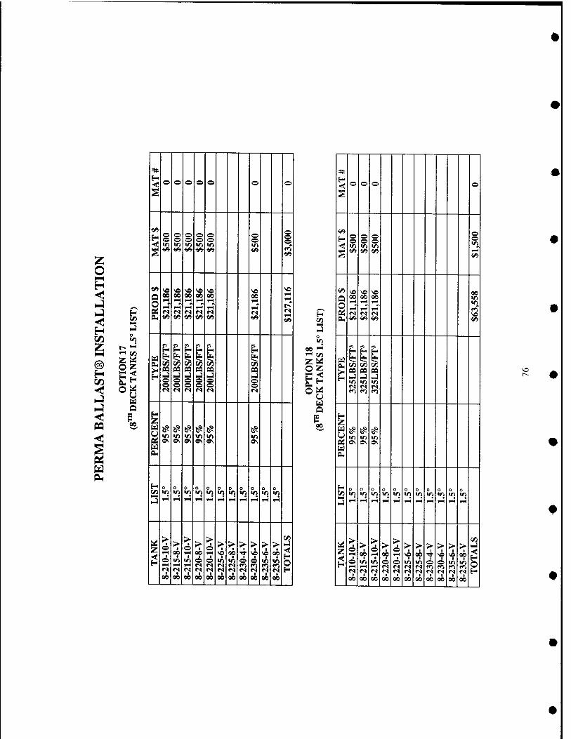
O H O
CO
Z
u
00
< o o o © o o o
o o o o •v
s
00 00 00
1^
00 I-H
I-H
SI
H n o o
OQ
o
09 BQ i ^ ^ 0\ 0\
V) 0\
^ s 0\
0 o
1-5
0
F4
o O o
1^
0
1-H
o
1-5
0
1H
o in
o in
z >
■ o rH
1 o ■
00
> I
'^ 00
> o
lA
00
> t
00 o
■ 00
1-1
1 00
5 00
> I
00
00
o
>
6 00
>
00 00
2 o
in
Z
U U
4): H ■<f o o o ©
s
o o o o § m ■"J" in m m S <^ <^ <» rH
<^ VO \o ve (n Q O
00 00 00 m »-H rH
rH 1—i
in
r» r^ «S Vf> D. <^ </> <* ^
f) rt ro H H
U s? 1^ s* Cu tn lyi !/) >- n oa oa u ̂ rJ m m m <N r< r< f^ r^ ro
H Z ^ ^ ^ m m in
Oi 0\ » o\ u eu
H a o o n o (/) m m m m m m in m in m m .J i-< 1-H rH rH 1^ rH T-t rH rH rH w^
Z > o > 1
> 6 >■
> ■ o > > > > > >
w^ 00 rH 00 rH "9 00 •* ve ve *? o in m o © in m © © m in 1—< I-H rH <s fS fS fS rri f^ f^ f<^ r^ fS r» <s '^ «s fM <S <s •? *? H 00 00 00 00 00 00 00 00 00 K 00
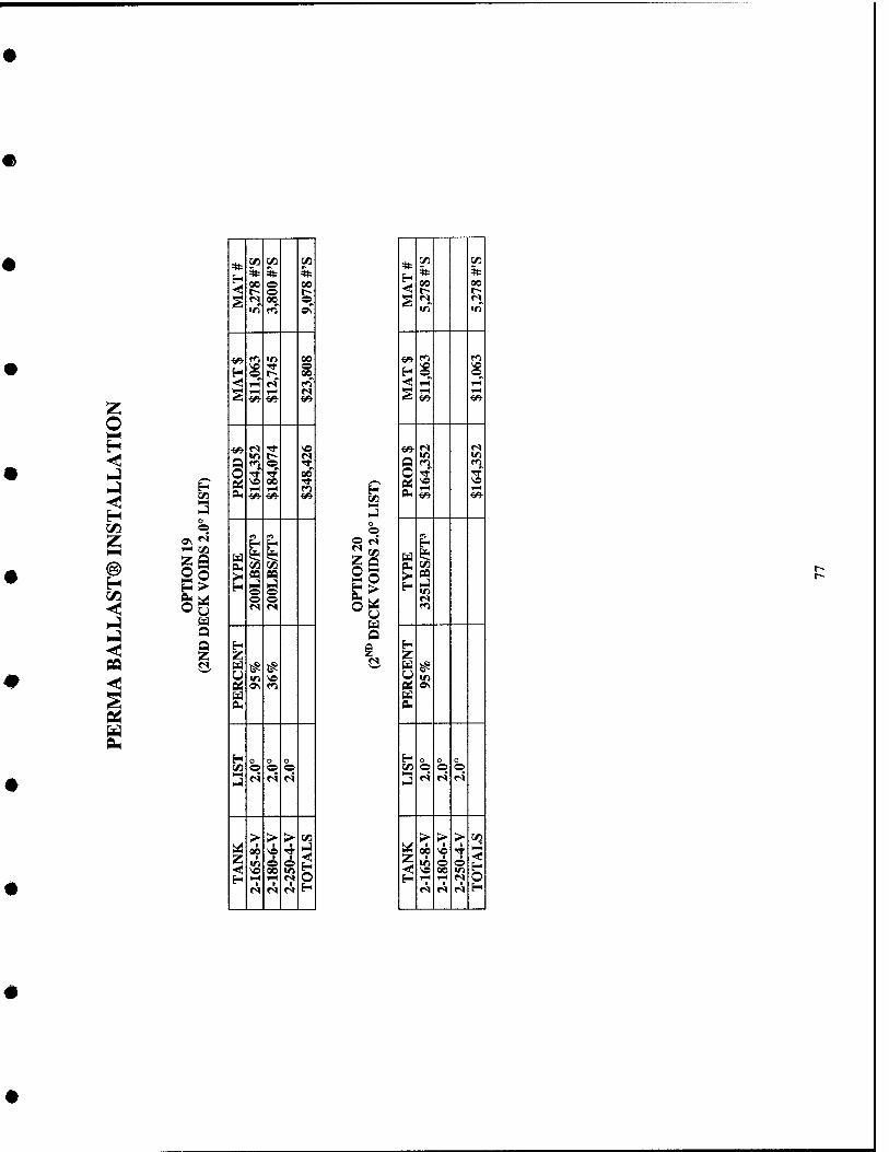
H
o H O
CO a o >
u
* M t» c«
H ft ft ft 00 O 00 r- O r--
5 n 00 © •n tn ON
-F/V ro V) 00 vo rr ©
H © r- 00 ^ rt «s fo S TH 1—1 «N ^ ^ ^
f^ «s ■* « «n i-> «N a (^ © TT
o •rr ^ 00
g so 00 TT l-H 1-1 ro «» i^ ^
m ^ ti ii! 1$ fV C/3 ^
^ 09 n .4 I-) o o o © r« <s
Eij 5^ ^ y tn « as o\ fO M 0M
H o o o t/i O © ©
3 rl «S M
> > > ■^ z 00 ve
I
1 H iH i^ r» M M r< H
«5
©
So ►n O
u a
ft CO CO ft 00
ft 00
§ in
^ so so H © © <! 1—1 TH
S TH
««■
U C1 f^ o Tf TT Pd SO
1-H 1-^ IX, ■e«- <«■
f) ■H
Ed ^ ^** PM lO >i ^ H 1-1
^ 2
pj ON u OH
H o o o (/) © © ©
3 r» r< r<
> > > Crt
Z 00 so
i f
i H o H i-i 1-1 'V
M r» f^ H
r-
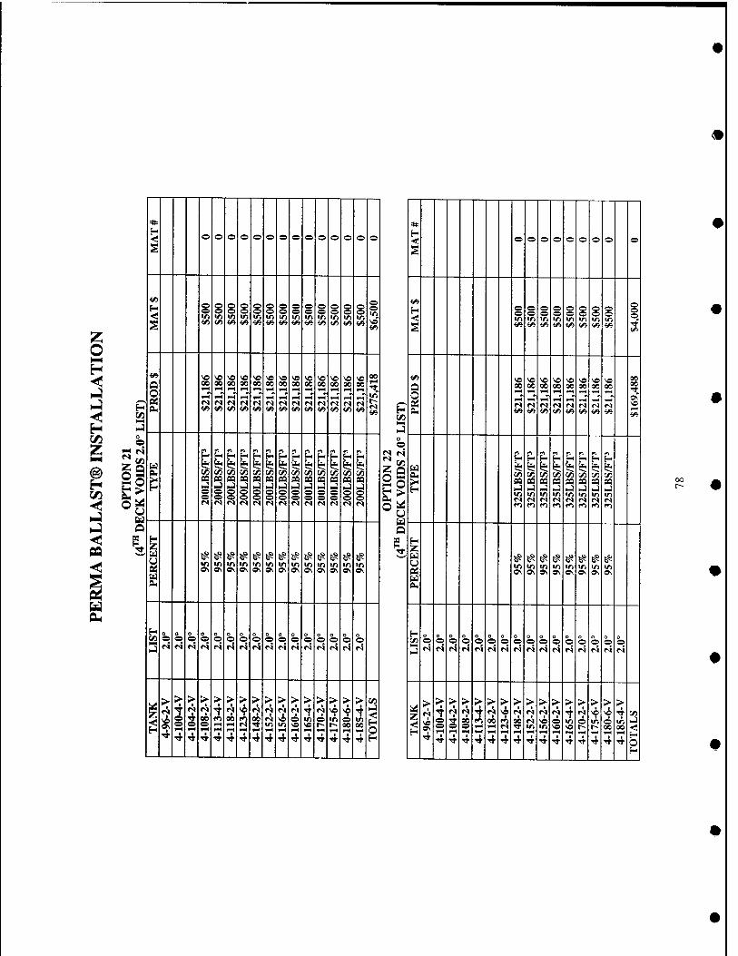
o O
©fad u u
e o e o o o e o © © © o © ©
S
i/i
H s s s g § o o § § g § © © § s S
"I "<' "^' m m Ifi Vt >n in m in •n m m
^
*» <« <A <« «» <« «» <^ fA v> <« ««■ v»
«> ve NO VO VO v© « ^ ^ ^ \o V) v> vn 00
Q 00 00 00 00 00 00 00 00 00 00 00 00 00 ■w 1^ ^^ T-l 1-^ w^ ?-H ^H FH
1" f^ ^H 1-H »H «s n <s n <s M »s ri >s r^ »s r» <S
h i« <^ v^ <^ </> «» <A ^ CA </> «» Vi «»
« rt « n <^ n H ^ H H |-H H f^
U 1* lj< fe* ^ 1^ li- (£< ^ ^ ^ ^ eu {/j t/j 1/3 C/) t/l (/I en cn r/1 en en r/1 rn >l Cfl PQ aa n « « pa oa n pa pa CQ pa H i-J I-) i-j u NJ HJ HJ .j ») hj ^ HJ ^
9 o e o e o © © o o o e o © © M <s M r» «s «s n «N «s «s M r» M
g u ^ ^ ^ # ^ ^ ^ ^ ^ ^ ^ t^ 5^
in 1/5 V) V) m tr> >n in m m m m in o\ »\ »\ 0\ o\ 0\ »\ OS 0\ ^ o\ o\ o\
H o o o 0 n . /^ O o O O O O © o o e © © © © e ©
J (S ri r4 ri «S «s fS «s N «s M N «s ri «s ri
> > > > > > > > > > > > > > > > c« 1* «s 't ^ '^ ^ N VO N ♦^ •? «S -f «s 4 \o >-l
< < ^
e s 00 fl SO f^ 00 «s ve © in e in A e o »-( ^H «s TT in m \o ve r~ t~- on 00 H TM 1^ iH 1—) t-H *-H f>H i-H w^ ^H »-4 O ^ 4 4 4 4 4 Tf ^ 4 4 4 t ■9 "<r 4 4 H
* H -*• © © © © o © © © ©
S
H <
p © © © © © o © © © ^ ^ ■^
m in m m in in m in s ■(/i <« vy {« i/i (A v> ^ S
«» ^ ^ \o so so >o so so Q O
00 00 00 00 00 00 00 00 FH »M T-4
i-H ^•^ FH 1-H *-^ 1-H * OS
ri <s r» rl <N r» r) r-i PH Vi <^ <« ««• «/> «/> V3- Vi <n
^M NJ o O
fS ri •^ ^ « <n >^ ,^
ii ^ H H i-i r" ka
^ 1* i* I* ie i? U. b U. a* in C/) ^ en en in en en >H pa pa pa sa aa pa sa a H ^ i-i u u u i-j u ^
m m m in m in in in »s «s r< fS <N (S <N »s f<i f»i m »^ f<i M rr> (»i
u
3, H Z
^ ^ ^ ^ ^ ^ # ^ «n m m m m m in m »v OS OS 0\ OS OS OS OS
H 0 0 o o 0 o
13 © O © © O e © e © © e © © © © © «s <s fS M «s <s «S JS «s «s «s «s fS N r» ri
> > > > > > > > > > > > > > > > tj; A M M i ^ ^ r<t «s N «s •? M so si 4 en
^ vn o s 00 t^ 00 f<1 00 «s SO o in © m © in ^ o © ^H 1-^ n ■>» m m so so r- r- on on •<•
H ' 1^ ^^ »-H 1-) 1-H FH »M 1-H F^
n 4 4 Tt '^ 4 4 4 ■^ 'S' 4 4 Tf Tt Tf Tf
H
00
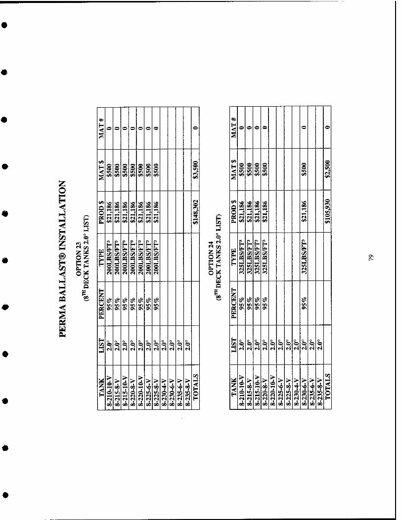
m
H in
o
O fe<! U
Q
00
* 0 0 © 0 © © © ©
S
««• H 0 0 ^ 0 © © © ^ 0 0 0 0 © © © ID -«f in V) m ID ID ID ID
S ■6» ^ <«■ <» f^ «© ««■ ^
^- ̂O « \o VC NO NO NO 1 § 00 00 00 00 00 00 00 rH FH l-H IH r-l TH rH TH ^ i-H 1—( T-l I-H j-t ^ tt «S «N «N <s <s «N «N
CL, <«• <«■ <^ *» <» «5- <«• ■^
^ H H H bj Z| £< 1*1 1$
y) C/5 ^ ̂ M x/^ VI n pa « P9 pa pa pa i-i i-j I-) hJ NJ hj HJ 0 0 0 © © 0 ^ 0 0 0 © © ©
n n r< ri ri r< fS
H Z 0 ^ ^ ̂ ̂ ̂ ̂ ̂
•n VJ V) ID ID ID «D Q:; ON a\ ON OS Os 0\ 0\ w eu
H 0 0 n 0 0 0 0 0 0 0 0 r/i 0 0 0 0 © © © © © © ©
«^ r< r^ «s n r» f^ r^ ri fS r<
z >
1 0 1H
>- > > > > > > > > >
H 0 H
00 00 vo 00 •^ "f NO 00 0 ID ID 6 © ID ID © © ID ir> 1^ r-( 1-H M n <S <S f^ tn ro r^ n M <? n <s <S n n r^ n <s 00 00 00 00 00 00 00 00 00 00 00
©
z^
u o 00.
© © © © © ©
«9-
H i 1 s § § ID
§ ID
i NO 00
rH
NO 00 rH rH~
NO 00
rn"
VO 00 T-i
rH~
V© 00 1—1
rn'
1;^ ID ©
pa 1-9
pa I-)
pa ID ID
H Z
ID ON
ID ON
ID ON
ID ON
^ ^
S ^■■4
iJ
0 © r4
0 ©
0 ©
0 ©
0 ©
0 © r4
0 © ri
0 © r4
0 ©
Z >
1 0
I © r-l
00
> 1
ID rH M
1 00
> © rH
1 ID rH
■ 00
> 00
1 00
> ■
1-1 1
I 00
> ■
00
> 00
00
>
• 00
> 1
SO
1 00
> 1
VO
ID r^ «? 00
> 1
ID
■ 00
2
OS
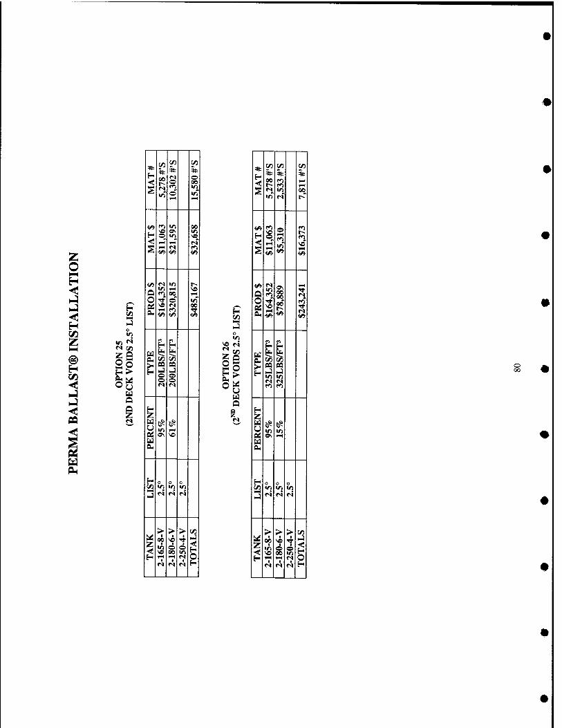
25
* 1/) 5»-
C/3 *
H 00 *s © ■< © 00
S © 1—1
f^ r^ *n 00
H \e o\ <r) © tT) ve
< »-H »N IS ^N r^ f^
<A Vi «»
w M in t-- W 1-^ ^ u ro 00 F-i
O •* © U1
£ *o «s 00 1-< f^ Tt «» i^ m
rt H H
u ie BU (/3 C^ >- QQ tt
NJ J © © O © *s <s
H Z
f-1
0« o\ VO u Su
E- o o o C/l V) IT) IT)
NJ n r» n
> > > C/5 Ui I ■
NO 1 U
Z !2 i © ^
H 1-H 1-H M Ir! r^ r^ r» H
(/J
is u
«s
* 02 c« 1/5
<< % * * 00 1*1 r~ r^ i—i
^ «s >n 00 V) <M 1^
</v f»i © (^ H ^
1-H
^ VO
^ 1-1 1^
I-H
•* 00 f) as I-H
rt ^ a 1*1 £( '^^ Bu ^ (/)
SQ tt U l-l VI l« ri r« f^ f^
H Z
^ t^ trt ir> tf e\ FH
u a.
H n o o c/i V) lO in
n fS <s
> > > C/) ^ ■
00 • ■ NJ
z ^2
■ © 00
© V)
O H iH rH <s r< <s r^ H
o oo
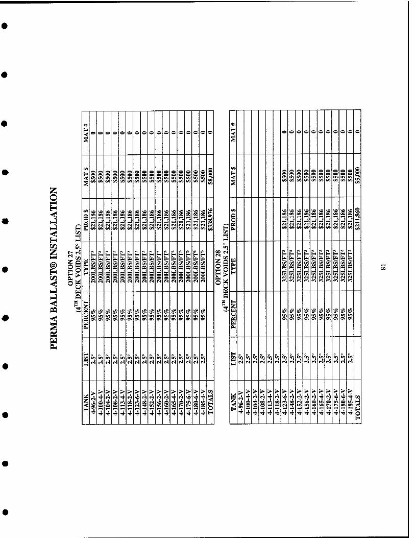
* * o o o o o o O o o o o o o o o o ®
o © O o o © © © © o ©
§
H ^-^ <—1 (—> r^ (-> (—1 l-> o e o o o O
(—1 o 9 © s ,-^ <-> o /-»! e o o ^ e (^ o o o o A o O o o ir> Wii v-^ '^ © -< ■r ■n ir> in in in in in in in in m >n in in ••al l/J 1/1 u\
^ ■£» Vi ^ ^^ ^ Vi Vi ^^ ^■ ^■ ««■ -^ Vi «« ^ ■^ ^^ §
«» vn vo \o ve vo >« vo ^ ve ^ 'O ve ve « \o ^o 0\
as- NO NO \e NO f "9 f f: NO vo 5? O 00 00 00 00 00 00 00 00 00 00 00 00 00 S 00 00 o 00
1—t 00 1X3
1-H FH 1-1 FH 1H4 *H HH 1—1 » o •>
-H I-( ^ s ^ 1—( 1-H i-H rH FH' 1-H IH ^H 1-1 1-H FH
^«^ frf r-l r» <s r» fS >s <s <s r^ IS <M <N n y—s n <N r-l «s n n fS f^ 21 !^ H OH ^ ««■ Vi {«• ■^ ««■ Vi •Sfi- vi M ^ ■ee- ^ ^^ <«• <«• H PH </s- </»• ■I/* t/i- (/* V* <y* SJ c« M NN _] 3
o O
ii ^ H H P- tfi pi P
LL 2J FH f^ F^ p. p m F^ *^, ^ H H fin
P P w
E: H
g t
r/1 r^ ^ ^ r^ % ^ ^ C« § g t/3 § ^ § ^ ^ S?i ^ ^
^ §
n 03 as SQ flft CQ n n n « n n P3 CQ PQ « ^
CQ n P3 *9 u PM '^ *1 *i W
J J _3 H^l _) _) C3 HJ KJ »:) »:) NJ l-J HJ i-l NJ H-) h-i i-l ^A I-l I-l J-l t-J >-i KJ r% o s o o e o S S o o o e m m 1/1 Vi o o /-^ o o o o 1^ o o o ^ o e o o &H ZA '^" r* J^' JT* fr^ M <s <s ri rl M M M <s <s n <S n M n n f> f) f) ft r») a fi r<j
o o i Ui fS f^ fS ES 5? ^ ^ ^ ^ # # # # ^ # ^ I i ^ ^ ^ ^ ^ ^ ^ # # ^
u in irt ir> lO in in in in in <n m in m m m m in m «r> in m m in «/) u> in 02 ON Ov 9. 9\ o\ Ov o\ 0\ ON o\ Ov o\ 0\ Ov ON o\ P4 Ov ON ON ON
u !^ &( EL,
H o n o H o O o o o o o o o o o o o o o !/) V) V) IT) m m m m m in in m m m m «n in t/3 m m in IT) m in in m m in in in "^ "i ".» iJ
M <s r4 M r5 (S f4 H r» N «s r<i f<i <s M «s NJ
r^ <s r» P^ <^ M r» »-» r» M r» r« r« M <S (S
> > > > > > > > > > > >• > > > 2 1 >- > > >■ > > > > > > > > > >■ > >
^ TJ> r!. <s 4 r^ ve n f\ <s 'i' 4 «? 4 ve 4 [* ^ Tt *? '^ T ^ ^ M A n rh Tt '^ "? \o T 2 <!
^ %
^ Tf on r^ on r»1 on r^ ve o in o in ^ m <c * ^ 4 00 r<^ 00 fS 00 <s NO o "^ © !^ o in
•fl*, o S o 1-1 «s Tt ir> m vs « r- r- 00 00 © o o FH 1-4 (S TT m m NO NO r~ t~ 00 00 H T-H 1-H TH 1-H FH TH rH rH rH I^ i-i »H »H IH rH H 1-1 rH •^ »H 1^ fH
■^ H rf 4 4 ■* ■^ TT TT TT 4 4 ^ 4 4 4 4 ■* H ^ 4 4 ^ ^ TT TT •* ■* Tf ^ Tf 4 4 4 4 O
H
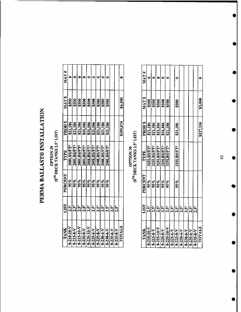
W3 «S
o z
o o o © © © © © © ©
S
o o © © © © § o o o © © © o © o ■< VI *n f) V) trt tt ID VI ■n s ^ <A <» f» ̂ <fi m i/i ^ ^
^ « « \o ve >e ve ve ve 'e Tf
§ 00 00 00 00 00 00 00 00 on I:; I-H rH 1-H IH i^ fH w^ w^ TH
rn'l •* ©
OJ ri r< r< *s »s «s •s fs •s Ov Oi ^ ̂ <«^ ̂ ̂ i^ ^ i^ i^ •^
^ H n n m P- n n
u I* t? z< z< C 1* (£< ^ ̂ OM (/5 ^ (/5 V5 WD V) W5 C/1 W)
^ n CQ n M 09 PQ CO n CQ HJ >-) N-) U NJ I-) _) ^ ̂ S o o S s © o <s f^l «s (S M «s r» «s <s
j^
z ^ ^ ^ ^ ̂ ̂ ^ ̂ ^ VJ </) V) in V) Irt VJ V) trt ce » OS 0\ o\ ON » o\ 0\ OV u
BU
H o o 0 o o o V3 tn >« *n «n «0 VI v> VI v> lO V) J r^ r« r* <s <S r< N N N «s fS
z > > >
A > > A > > > > > > 2
1 lH «? rH 00 IH ^ «? TT ve ve «? e «n m © © VJ v> 6 ̂ ■n ID t-( i-< iH rv« r« r< «s fo f^ f^ f^ f;* ';' *? «V <S r» r^ r< <s r< n H 00 00 00 00 00 00 00 00 00 00 00
«5
©
Z o
< © © © © © © ©
© ©
© © v> VJ
s vt V)
Q O
so 00
ve 00
ve 00
ve 00
FH"
ve 00 1-H
ve 1-H
«^ 1^
£ ^
aa V)
pa v> v> V>
s v>
1 u ̂ s
^ ^
^ ^ VJ V)
^ ^
^ N^ ^
o V) ri
o V) r4
O VI r4
0 o VJ r4
o v> r4
o v>
o VI
o V} ri
o V>
o v>
z
2
> 1
00 ■
VJ rH
I 00
> 1-1
v>
oi>
> 0&
■ o
00
> o
■ ©
0^
> ■
ve ■
v> <s *? 00
> 1
00
iq •
00
> ■
■ 00
>
©
1 00
> 1
ve V) rj
1 00
> ■
00 ■
2 o
oo
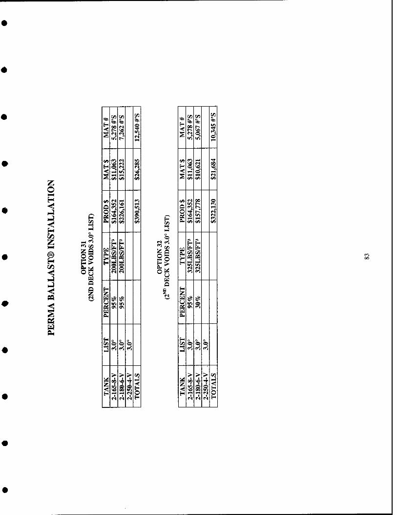
f^ xn
2P >
u
r<
C/l r/i M 4t
00 * s
* o
S
-F/V f^ rq v> 'O «s 00
H o (S «N y-^ *n vo
^ I-H l-H n ^ *e «»
•w «s lH r^ IC « 1—1 (_) fi IH «D
o TT V© O
g vo «N »v r-( ri f^
■6» «^ ««■
rO rt ^
u 1$ l*< o3 C/3 M
^ pa CQ h4 ^ o o o o «s n
H z ^ ^ *ri V)
tf o\ 0\ u Oi
H o t/l o o o ^iN NJ
VTi f^ ro
> > > C«
op
V©
v© 6 00
o
l-l 1 H »-H »H r» r« n «^ H
So H
O
Q
*
<
ly) C/5 C«
* * 5t
?5 % (N o
in yrt © 1—1
ff\ r<1 rH rr VO n 00
H o VO « rH d" i-H
^ iH 1-1 »S ■e» <«■ </5-
■w «s 00 O m r- f*^
(4 fO r- iH
o t r- «S
g ^ ir> «N rH 1-1 •^ -^ ^ ^
rrt f-H
Ed fe? 1* (^ t/5 ^
^ « pq >-i l-l V> <n r^ fS r^ f^
H Z
5^ ^ VI o
Qj »v VTk
M PH
H c/) O o o
fO f<^ fTi
>► > > (/3
z <
00
58 so TT
g >-l
1 H TH 1-H r« r< fS M H
en oo
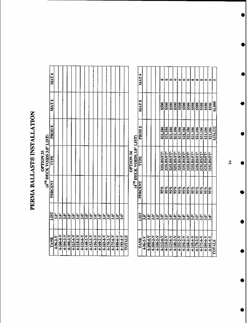
«1
o
e
* * H H ■< -if o e o o © o © © o © © © ©
s s
^ w* H s 1 s § § s g § s ©
© § § l/> iri trt V) IT) in IT) IT) W1 in m in <« «« Vi <A «« ff> Vi <« <«• M ^ w VO
^ <» Nfi v« « ve ^e so se VO VO v? V) vi
5- 1 00 00 •>
90 1H
00 00 00 00 1-H
00 00 00 1-H
00 00
E ?! '^ «S r^ «s <s s M <M «s «s «M »s m eu, ^■ <« Vi w «A <A^ <«• <« ■£«• <«• <» f/i
!-■
O — — — O
io
f^ *^ KJ m n f^ f-H ^ t-i^ H H H ^
u \Xi 1* 1* l*c I? tj< fe* ^ ^ s? &- ^ &
tAi t/) M t/1 (/5 C/1 C/1 t/1 t/1 en r/i r/i >< (Q n BO aa n sa n CQ oa aa oa oa H H i-J NJ >J HJ >-) >j ^ U .4 j MJ NJ
trt tn IT) •n m IT) trt m iri m in in 2* C «S •s «s r< «S n <s «s <s fS «») ro to i»> rrt ro f<l r<^ ff> c<% f^ rrt
u
I # ^ ^ ^ ^ ^ ^ ^ ^ ^ ^ ^ >n m U1 v> V) m ITi 1/) in •n m in o\ o\ «\ 0\ o\ »\ 0\ Ov o\ »v o\ 0\
eu £
H o O ^ h 0
O o e o
O h ^ o o O
0 O
o O
o O b h o
52 o O
o O
o e h h> o o e o o o
O o © h o
O 0 ©
O ©
o ©
0 ©
>J f^ f») fo fl f<i f^ f^ <*> fr> tn m fr» t^ f^ f^ f«^ NJ «0 f> f^ fo fV ro »^ M f»l r^ r<) f<1 f^ ri m f^
> r ■
> > > > > > > > > > > > > > 1/)
1 > >■ > > > > > > > > > > > > > >
1^ r^ • «S • '•o r? M A ^ i ^ ^ ve 4 i^ ^ 4 '^ 'i' •^ '^ NA r^ r^ N <s 7 !2
ci 4 VO
in 00
cn
^ S 1-H s S
rH 00
^H
GO
1-^ R o !2 e S ss
^ ^ i i o 00
?^ 00 N m in i ^ © 00
4 4 4 4 4 4 4 4 4 4 4 4 4 4 4 1 <* ■ 4 4 4 4 4 4 4 4 4 4 4 4 4 4 S _J _ _ _ H
oo
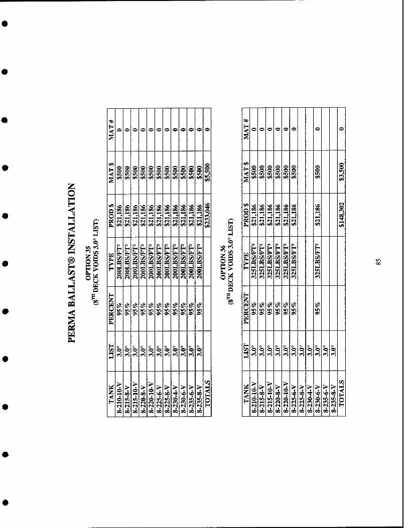
H
o
2o AH
o
=»: H -< © o © © © o © © © © o ©
S
•e«- (—> H
(^ © o o © © © 1^ ^s © © .-> Q © © © © © © o o © © ir)
■«»' m in ■n v> m m <r> V) *n in ^ s ^■ ^5- ■£«• «^ «e ̂«- <«• <«■ <«■ ■e» <A ̂
•^ so ve VO VD so v« so VO so so so so o oo 00 00 00 00 00 00 00 00 00 00 o FH rH 1—H ^^ ^H r? ^ fs <s r^ <S <N <s <s M M »s n PUl ^fi- ̂ ^ ^^ ■«» <^ ̂ ̂ ^ ««■ ^• <«• ̂
m m m m ^ H H ^ -H H
w ̂ ^ fet< i? l*< t? i*i S( ^ 1$
> V\ W3 WD t/l W ̂ C/1 ^Sl ;/) C/1 TJ^
PQ pa ea pa pa pa pa pa pa pa pa NJ hj HJ NJ NJ MJ ^ HJ hj i-j NJ o © © © © © © © © o © © © o © © © © © © <s n fS r< r« fM <s <M r< n fS
H Z
^ ^ ^ ^ ^ ^ ^ ^ ^ ^ ^ in m m *n •n *rt V) IT) «n m m
Q£ 0\ o\ ON OS a\ 0\ a\ a\ *N Ov 0\ U 0H
H o o o O o o i/1 o o © © o © © © © o ©
3 fo f^ t^ f^ f<% tr^ f^ f} fTi fo trt
ui > o > > 1-1
> > > > > > > >
:««.
^ 00 00 vc 00 -T ̂ ^ «?
O ■n •n © © m m © © m m i-H 1-1 TH <N r^ «N «s f^ r^ f<i <^ r< n n <V r« fS «s n »M n «s 00 00 00 00 00 00 00 00 00 00 00
H iZl
©
2o
Q
*
© o © © © o © ©
s
«^ H f—5 f^ (^ (^ © © o f^ ^ ^ ^ ^ © © © ir>
«ri «n «n m m m in m S ^ *«■ <» <«■ «^ *» </5- ^
«» v« vo so so so VO SO O 00 00 00 00 00 00 00
rH v^ 1-1 ^H iH 1—1 l-H o iH 1—1 iH ^H l-H l-H l-H ^ oi «S «S «s «N «s ri n OH «^ ̂ <» «»■ i«- «e <«• ^
^ H H &d i? ̂ ^ i$ 1$ ni ̂ t>^ (/: M X/l ^ M
^ pa PQ pa n n pa pa I-) HJ j hj H-) ..j i-j <r) m m m m in m <S «s fS «s «N «N fs f^ f^ f^ f<^ ro f) to
^ z ^ ^ ^ ^ ̂ ^ ^ m m m m in m m
1 »N o\ OS o\ OS OS a^
H 0 n o o o o o o o o o r/) © O © © © © © © © © ©
N-l rfi f^ fi fO f^ fTt fTi fT) ro fO fTi
M z ^
> © 1
00 © 1-4
> 1
00 o 1-1
> > I
> 4
>• so SO
> 00
2 O 6 m m © © in m O © m in
l-H l-H 1-4 «s n n *s fO f»1 ro ro <v ^ •V «s rq r» n (S r« f<l n H 00 00 00 00 00 00 00 00 00 00 CO
in 00
Appendix D: Preliminary Cost Comparison
86

"~" ~ 00 s ^ SS o s ■g ^
fi 30
Q ■*
ja
i-i in (N
a ^ .id P-' «; u-i 9
S 1
^ n? 00 ;cs >? s a s n o ■* r- f*i -^
O ^ «N «n O
Tl CO
Vi rs ^ VO n y? o \D so oo
J^ s *n m •n o
a R en ICl l*^
•C r-
-y 00 ^ s a s 3, (TN
(1^
X ii '"'
S r^
■3 (N en
Q (TV so
1 (N
1^ o m ■^l •^
«^ >r 9 m (*1
-c
00
^ 1
^ ^ p 2 o r4 s o
t_J oo ^. 1 s (N
r^
tl
^ 1^
S rj r- o
1 " w
1 oo s S SR O s U1 1 (Ti o
so —. i
£
^ oe
^ i^ — o o m m
1 t U s 1 6
■"'
r-i
t r-i "« m o <^ oo 00 ri ■n
" ^ ^ S s !S O S ^ K
u> 9 U M 3 00
o ■i^ S; 8 !Ci Q s? - Z3
V) .a
r- ?; r- ■T ri
O en oo I-'
S
:q fN M rs ■^ -t cs
^ fi fi o
JS —' T-«
^'-^ ^ S^ ^ !S s O TT ss; s w-i m t-;
m
o ^ rt
« 1 K 1 S S
U r
s d
(N
Tl — '^
R r r^ «A ^J o o
e 3
I a 1 1
1 n
! 1
C u i 1
1.
■c
1
1
1 i £
<
~ o s S s o s s OS
■g oo r-i' K 1H 9 ft » 00
„ 1—, <n r- r^ ^ 1 t rf SO 9
8 1 o ^ TT n n «N o
1 so — SO Wl n ^ >n
ro
(-1 so o (N M
f» 3 in S m ^ rj
U y 5
JT
T5 1 ^ 1 z
' s rvi
i5 »n OJ n oo Tf
ft »s r^
m
(S
VO r^ r-) fo r*% ^ 11 ^ r- s 1 :;' 9
ri so 00
-O J4 ^ ^ |C !« O Cs OO oo ^
ou <_» = oo
J ft n
>o so S (^ OS Os OS
« f» p- f^
W)
c
r4 it s o ^ O ^ ^ in
so o o 9 o -t ft
-r
00
^ s ^ R ts o so i^ ^ CM o SL> "i 00 9
U rr>
s "<r
^ ^ 1 sn in o
(N s -* r<
^ o fM
-Jl W) Uj uu 9 ft SW
00
o f^
M
a s -3- OS g » a
1 ts ^ a ^ ^ !^ ^ ;_> »/n OS •n
.? — Os 2 5!; ^ M
S r- r^
-g Cl m oo o
xa ^
■JT
00
^ oo s o \S o 2 2S s a ■^ m ■n r- r- 9 A M r- ^ .?; ^ S 1*
~ \n «n OS irj r-
Si n fo
■rt Uj Tt ro O
(M
r o !i' jy rJ o S
3
>
1 1 O U
f c U 1
■a ■s
1 ft 1 £
^ ^ 1 tSi ! 1 1 <

Appendix E: Complete Structural Analysis
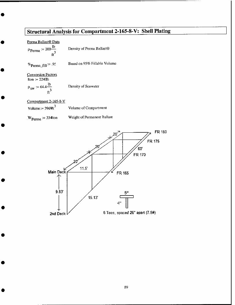
structural Analysis for Compartment 2-165-8-V; Shell Plating
Perma Ballast® Data
PP: erma :=200A
ft^
Density of Perma Ballast®
/"Perma fill :=.9f Based on 95% Fillable Volume
Conversion Factors Iton := 224ab
lb Psw:=64.4— Density of Seawater
ft
Compartment 2-165-8-V
Volume := 3969ft^ Volume of Compartment
^Perma •" 354ton Weight of Permanent Ballast
Main Deck
9.83*
2nd Deck
FR180
FR 175
6 Tees, spaced 26" apart {7.6#)
89
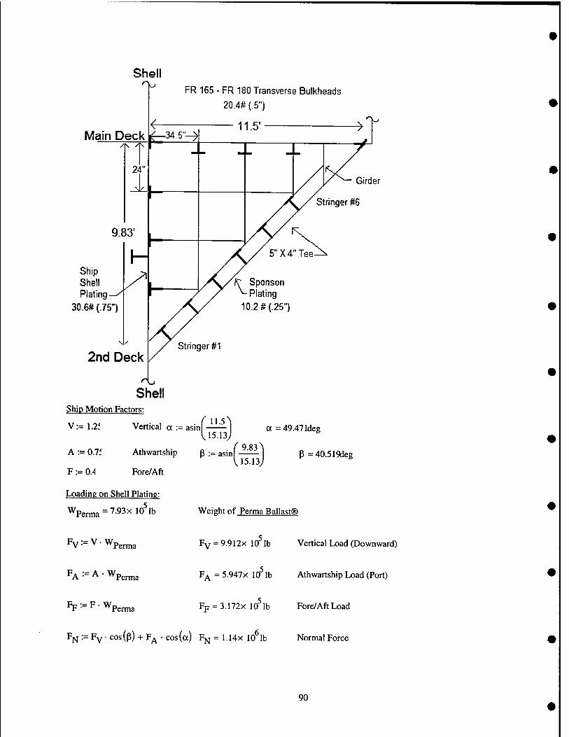
Main Deck
FR 165 - FR 180 Transverse Bulkheads
20.4# (.5")
11.5* >
Ship Shell Plating
30.6# (.75
Girder
Stringer #6
10.2 # (.25")
2nd Deck
Shell Ship Motion Factors:
V := 1.2f Vertical a := asinf^^
A := 0.7f
F := 0.4
Athwartship p
Fore/Aft
V1513 . (^9.83
:= asm • V 15.13
a = 49.47 Ideg
P =40.519deg
Loading on Shell Plating:
Wperma = 7.93x10^ lb Weight of Perma Ballast®
Fv:=V-Wp,^,
F^ := A • Wpg^3
Fp :- F • Wpgj.j„3
Fy = 9.912X 10 lb Vertical Load (Downward)
F^ = 5.947X 10 lb Athwartship Load (Port)
Fp = 3.172X 10 lb Fore/Aft Load
% := Fy ■ '=os(P) + FA ' cos(a) F^ = 1.14x 10^lb Normal Force
90
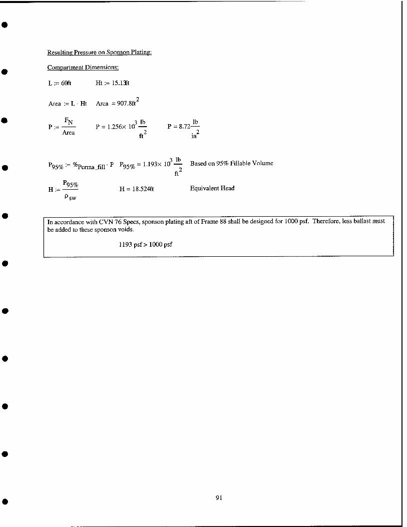
Resulting Pressure on Sponson Plating:
Compartment Dimensions:
L := 60ft Ht := 15.13ft
Area := L ■ Ht Area = 907.8ft^
P:= ^N
Area P = 1.256X 10"
.3 lb
ft
P = 8.72— . 2 m
^95% '■= %erma_fill' ^ ^95% = ^"^^^^ ^^ — ^^^^^ °" ^^^^ F^"^^^® Volume .3 lb_
.2 ft
H:= ^95%
sw H = 18.524ft Equivalent Head
In accordance with CVN 76 Specs, sponson plating aft of Frame 88 shall be designed for 1000 psf. Therefore, less ballast must be added to these sponson voids.
1193 psf> 1000 psf
91
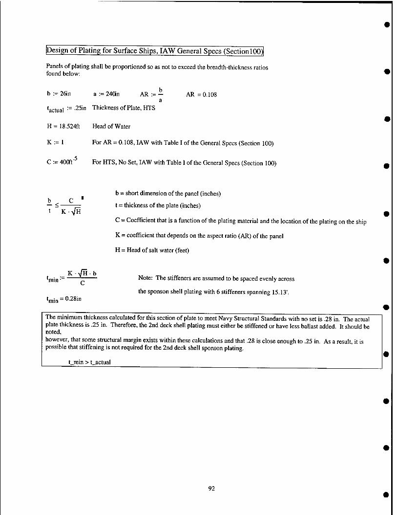
Design of Plating for Surface Ships, lAW General Specs (Section 100)
Panels of plating shall be proportioned so as not to exceed the breadth-thickness ratios found below:
b := 2fin a := 240in AR := — AR = 0.108 a
^actual :== •25in Thickness of Plate, HTS
H = 18.524ft Head of Water
K := 1 For AR = 0.108, lAW with Table I of the General Specs (Section 100)
C :- 400ft'^ For HTS, No Set, lAW with Table I of the General Specs (Section 100)
b c ■ — <• K>/H
b = short dimension of the panel (inches)
t = thickness of the plate (inches)
C = Coefficient that is a function of the plating material and the location of the plating on the ship
K = coefficient that depends on the aspect ratio (AR) of the panel
H = Head of salt water (feet)
K-VHb ,, rr,, ... *min ■" "^ Note: The stirfeners are assumed to be spaced evenly across
the sponson shell plating with 6 stiffeners spanning 15.13'. C
^min = 0.28in
The minimum thickness calculated for this section of plate to meet Navy Structural Standards with no set is .28 in. The actual plate thickness is .25 in. Therefore, the 2nd deck shell plating must either be stiffened or have less ballast added. It should be noted, however, that some structural margin exists within these calculations and that .28 is close enough to .25 in. As a result, it is possible that stiffening is not required for the 2nd deck shell sponson plating.
t_min > t_actual
92
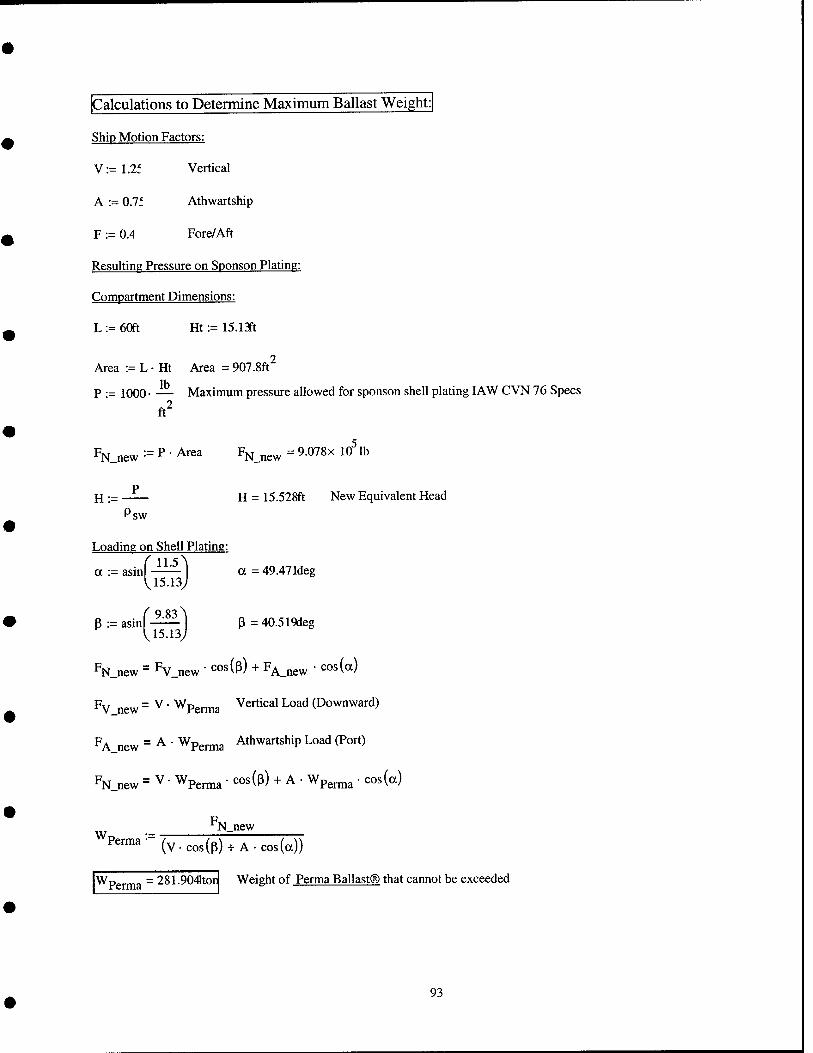
Calculations to Determine Maximum Ballast Weight:
Ship Motion Factors:
V:=1.2f Vertical
A := 0.7f Athwartship
F := 0.4 Fore/Aft
Resulting Pressure on Sponson Plating:
Compartment Dimensions:
L := 60ft Ht := 15.13ft
Area := L • Ht Area = 907.8ft^
P ■= 1000- •— Maximum pressure allowed for sponson shell plating lAW CVN 76 Specs
ft^
FN_new == ? " Area FN_new = 9.078x 10^ lb
p H := H = 15.528ft New Equivalent Head
Psw
Loading on Shell Plating:
a = 49.47 Ideg . f 11.5 a := asm
U5-13
P := asinf-^ I P = 40.519deg
pN_new = Fv_new ' cos(p) + F^jiew " '^os(a)
Py new = ^ ■ Wperma V^^ical Load (Downward)
FA_new = ^ • Wp^^^ Athwartship Load (Port)
% new = V • Wperma " cos(p) + A • Wp^^^ • cos (a)
N_new
^P^™^ ''^ (v.cos(p) + A.cos(a))
^Perma = 281.9041ton Weight of Perma Ballast® that cannot be exceeded
93
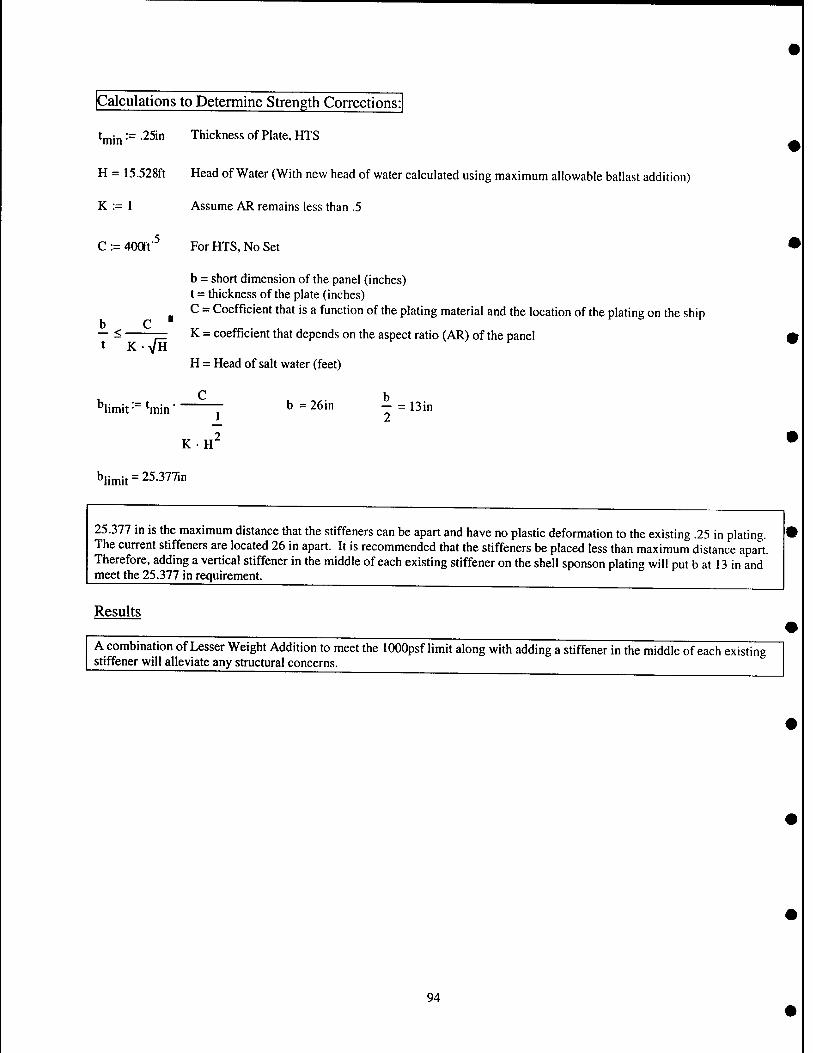
Calculations to Determine Strength Corrections:
tjjjjn := .25in Thickness of Plate, HTS
H = 15.528ft Head of Water (With new head of water calculated using maximum allowable ballast addition)
K := 1 Assume AR remains less than .5
C:= 400ft'^ For HTS, No Set
b = short dimension of the panel (inches) t = thickness of the plate (inches) C = Coefficient that is a function of the plating material and the location of the plating on the ship
K = coefficient that depends on the aspect ratio (AR) of the panel b — <
K-VH H = Head of salt water (feet)
C h ''limit '■= ^min T ^ = ^^i" T = 13in
KH
''limit = 25-377in
L 2 2
25.377 in is the maximum distance that the stiffeners can be apart and have no plastic deformation to the existing .25 in plating. The current stiffeners are located 26 in apart. It is recommended that the stiffeners be placed less than maximum distance apart. Therefore, adding a vertical stiffener in the middle of each existing stiffener on the shell sponson plating will put b at 13 in and meet the 25.377 in requirement-
Results
A combination of Lesser Weight Addition to meet the lOOOpsf limit along with adding a stiffener in the middle of each existing stiffener will alleviate any structural concerns.
94
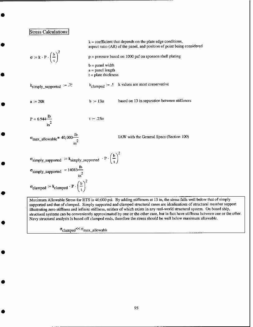
Stress Calculations:
a := k • P •
''simply_supported •
k = coefficient that depends on the plate edge conditions, aspect ratio (AR) of the panel, and position of point being considered
p = pressure based on 1000 psf on sponson shell plating
b = panel width a = panel length t = plate thickness
lc,i fi := -5 ^ values are most conservative
a := 2Qft b := Bin based on 13 in separation between stiffeners
P = 6.944- Jlb_ . 2 in
t := .25in
^max allowable= 40,000 Jb_ . 2 in
I AW with the General Specs (Section 100)
^simply_supported • Simply_supported
,., lb ^simply_supported
"■'7
14083
in
^clamped • "Clamped I ^
Maximum Allowable Stress for HTS is 40,000 psi. By adding stiffeners at 13 in, the stress falls well below that of simply supported and that of clamped. Simply supported and clamped structural cases are idealizations of structural member support illustrating zero stiffness and infinite stiffness, neither of which exists in any real-world structural system. On board ship, structural systems can be conveniently approximated by one or the other case, but in fact have stiffness between one or the other. Navy structural analysis is based off clamped ends, therefore the stress should be well below maximum allowable.
^clamped ^max_allowabl(
95
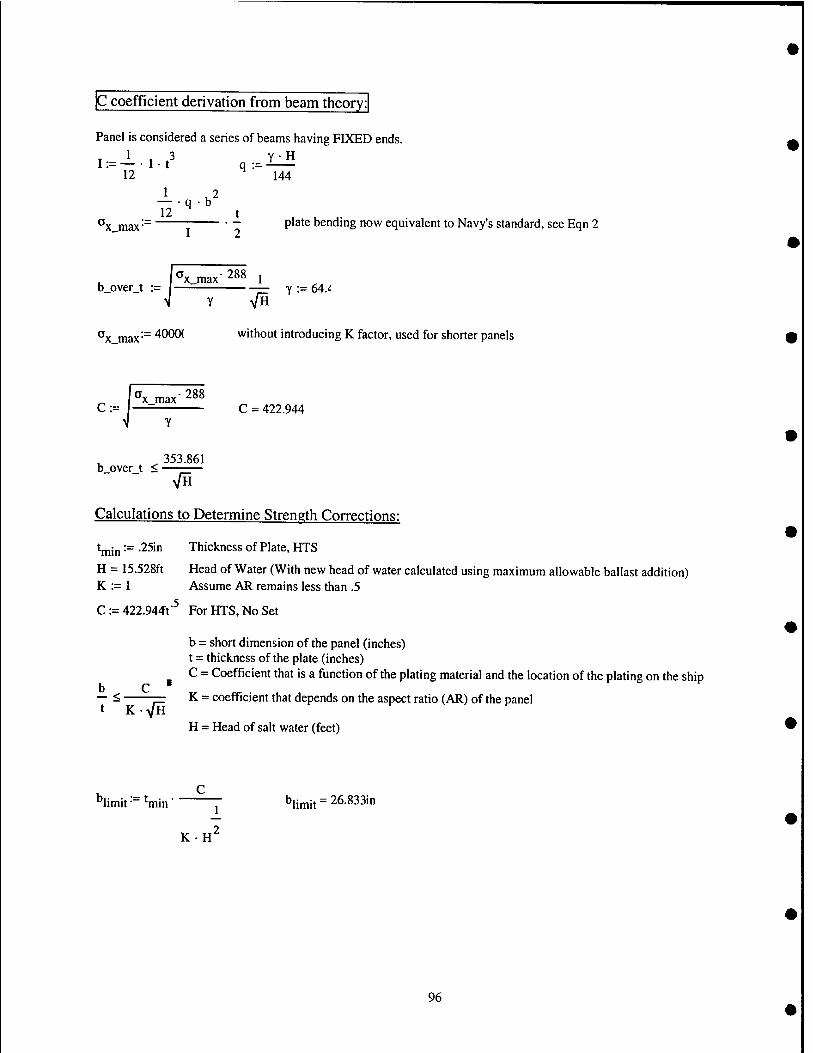
C coefficient derivation from beam theory:
Panel is considered a series of beams having FIXED ends. 1,3 Y-H
I := — • 1 ■ t q := -^ 12 ^ 144
12 ^ t Ox_max-~ ■ ~ P'^'^ bending now equivalent to Navy's standard, see Eqn 2
Nx_max'288 j b_over_t := j y := 64.'^
V Y VH
^x max'" ^^^ without introducing K factor, used for shorter panels
^ Px max-288 C := —= c = 422.944
353.861 b over t < •
Calculations to Determine Strength Corrections:
^min ~ ^Sin Thickness of Plate, HTS
H = 15.528ft Head of Water (With new head of water calculated using maximum allowable ballast addition) K := 1 Assume AR remains less than .5
C := 422.944Ft'^ For HTS, No Set
b = short dimension of the panel (inches) t = thickness of the plate (inches) C = Coefficient that is a function of the plating material and the location of the plating on the ship
b — <■
K-VH K = coefficient that depends on the aspect ratio (AR) of the panel
H = Head of salt water (feet)
^limit ■- 'min j" ^jjj^^ = 26.833in
2 KH
96
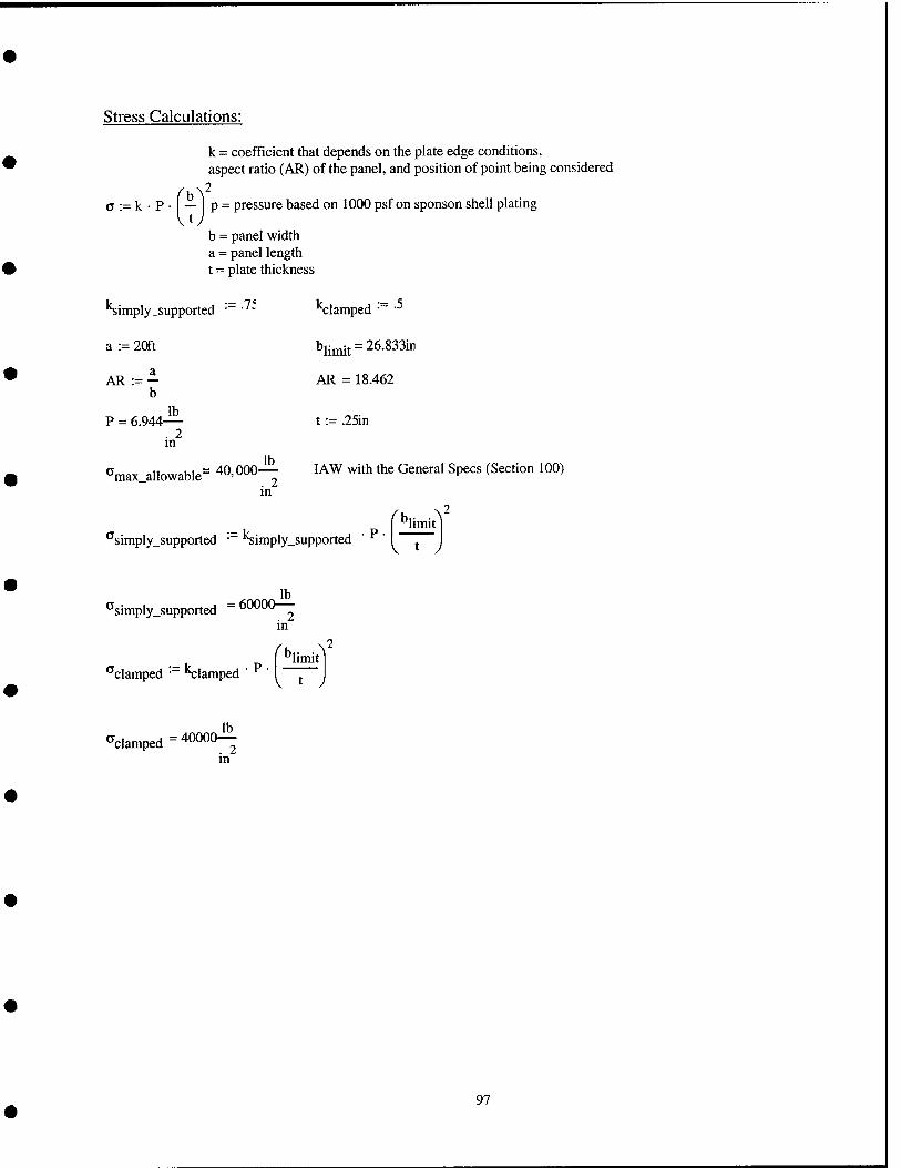
Stress Calculations:
a := k • P
k = coefficient that depends on the plate edge conditions, aspect ratio (AR) of the panel, and position of point being considered
— p = pressure based on 1000 psf on sponson shell plating
b = panel width a = panel length t = plate thickness
"Simply^upported ■ ■ Clamped :=.5
a := 20ft blimit=26.833ir
b AR = 18.462
p = 6.944— . 2 in
t := .25in
*^max_allowable~ 40,000 lb
. 2 m
lAW with the Gei
'^simply_supported • Simply_supported ' ' ^_^limit^
^simply_supported 60000-^ . 2 in
^clamped • Clamped ■P-
V t J
clamped 40000^ . 2 m
97

structural Analysis for Compartment 2-165-8-V: Ship Shell Plating Inner Longitudinal Bulkhead
Perma Ballast® Data
PPerma ■- 200-!^ ft
^"Perma.fill •= ■^'
Conversion Factors
Iton := 224ab lb
sw ft"
Compartment 2-165-8-V
Density of Perma Ballast®
Based on 95% Fillable Volume
Density of Seawater
Volume := 3969ft Wperma-=2811ton
Volume of Compartment
Maximum Weight of Permanent Ballast that can be added in accordance with shell plating
stress calculations
Main Deck
9.83'
2nd Deck
FR180
FR175
6 Tees, spaced 26" apart (7.5#)
98
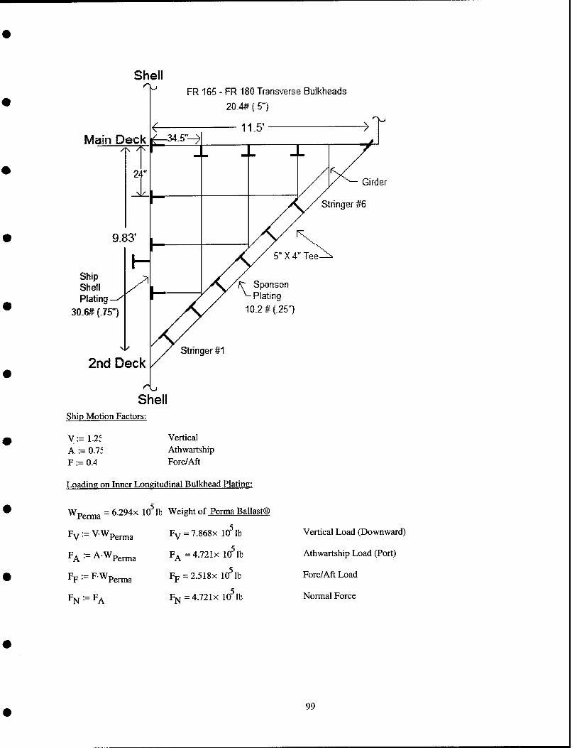
Main Deck
FR 165 - FR 180 Transverse Bulkheads
20-4# (-5")
11.5' >
Girder
Stringer #6
Ship Shell Plating
30.6# (.75")
2nd Deck
Shell Ship Motion Factors:
V:=1.2f Vertical A := O.li Athwartship F := 0.4 Fore/Aft
Loading on Inner Longitudinal Bulkhead Plating:
Wpgj^a = 6.294X 10 lb Weight of Perma Ballast®
Fy := V-Wperma
FA ■= AWpenna
Fp:- FWpgj^jjja
% ■- ^A
FY = 7.868X 10 lb
F^ =4.721x 10^ lb
Fp = 2.518x 10^ lb
Fj^=4.721x 10 lb
Vertical Load (Downward)
Athwartship Load (Port)
Fore/Aft Load
Normal Force
99
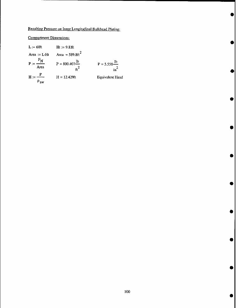
Resulting Pressure on Inner Longitudinal Bulkhead Plating:
Compartment Dimensions:
L := 60ft Ht := 9.8 Jt
Area := L-Ht Area = 589.8ft^
Area P = 800.407—
ft^
H = 12.429ft Psw
P = 5.558-1^ . 2 m
Equivalent Head
100
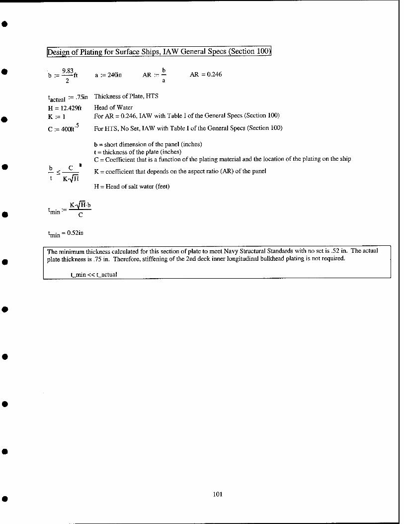
Design of Plating for Surface Ships, lAW General Specs (Section 100)
b := —ft a := 24an AR := - AR = 0.246 2 a
Wual •= •'^5'" Thickness of Plate, HTS
H = 12.429ft Head of Water K := 1 For AR = 0.246, lAW with Table I of the General Specs (Section 100)
C := 400ff^ For HTS, No Set, lAW with Table I of the General Specs (Section 100)
b = short dimension of the panel (inches) t = thickness of the plate (inches) C = Coefficient that is a function of the plating material and the location of the plating on the ship
b C ■ — < K = coefficient that depends on the aspect ratio (AR) of the panel
t,
K-VH
K-y/Hb
H = Head of salt water (feet)
min" p
Wn = 0-52in
The minimum thickness calculated for this section of plate to meet Navy Structural Standards with no set is .52 in. The actual plate thickness is .75 in. Therefore, stiffening of the 2nd deck inner longitudinal bulkhead plating is not required.
t min «t_actual
101

Calculations to Determine Strength Corrections
'min '■= •'^^'" Thickness of Plate, HTS
H = 12.429ft Head of Water (With new head of water calculated using maximum allowable ballast addition) K := 1 Assume AR remains less than .5
C := 400ft'^ For HTS, No Set
b = short dimension of the panel (inches) t = thickness of the plate (inches) C = Coefficient that is a function of the plating material and the location of the plating on the ship
K = coefficient that depends on the aspect ratio (AR) of the panel b — <■
K-VH H = Head of salt water (feet)
•'limit :=tmin- f b = 58.98in
2 KH
•'limit = 85.096in
85.096 in is the maximum distance that longitudinal stiffeners can be located apart and have no deformation occur to the .75 in plating. The current stiffener spacing is approximately 58" and well within the limiting width between stiffeners. As a result, the inner longitudinal plating does not need to be stiffened.
102
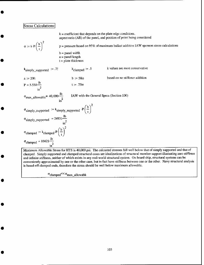
Stress Calculations:
o := kP- -
k = coefficient that depends on the plate edge conditions, aspect ratio (AR) of the panel, and position of point being considered
p = pressure based on 95% of maximum ballast addition I AW sponson stress calculations
b = panel width a = panel length t = plate thickness
^imply_supported
a := 20ft
P = 5.558— . 2 m
lb ^max_allowable= 40,000—
in
k values are most conservative
based on no stiffener addition
"^clamped •
b := 58in
t := .75in
lAW with the General Specs (Section 100)
■^simply_supported • ^imply_supported
simply_supported 24931— . 2 m
^clamped • Clamped
'^clamped =16621— . 2 m
Maximum Allowable Stress for HTS is 40,000 psi. The calcuated stresses fall well below that of simply supported and that of clamped. Simply supported and clamped structural cases are idealizations of structural member support illustrating zero stiffness and infinite stiffness, neither of which exists in any real-world structural system. On board ship, structural systems can be conveniently approximated by one or the other case, but in fact have stiffness between one or the other. Navy structural analysis is based off clamped ends, therefore the stress should be well below maximum allowable.
"'clamped ''max_allowabl(
103

structural Analysis for Compartment 2-165-8-V: Transverse Bulkhead Frames 165,170,175, and 180
Perma Ballast® Data lb
P Perma
%
:=200-
Perma fill ■
ft .9f
Density of Perma Ballast®
Based on 95% Fillable Volume
Conversion Factors
Iton := 224ab
sw :=64.4^
ft^
Compartment 2-165-8-V
Volume :=3965ft^
Wperma:=2811ton
Ship Motion Factors:
V:=1.2f
A := 0.71
F := 0.4
Density of Seawater
Volume of Compartment
Maximum Weight of Permanent Ballast that can be added in accordance with shell plating stress
calculations
Vertical
Athwartship
Fore/Aft
Loading on Transverse Plating:
Wpg^3 = 6.294x lO^lb Weight of Perma Ballast®
Pv^=V.Wp,rma
FA -■= AWperma
FF^=FWpe™3
% •- Pp
Fv = 7.868x 10 lb
FA=4.721X 10^ lb
Fp = 2.518x 10^ lb
FN=2.518X 10 lb
Vertical Load (Downward)
Athwartship Load (Port)
Fore/Aft Load
Normal Force
104
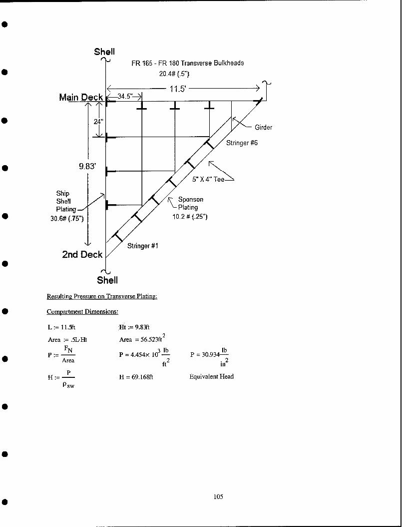
Shell
Main Deck
FR 165 - FR 180 Transverse Bulkheads
20.4# (.5"
11.5' >
Girder
Stringer #S
Ship Shell Plating
30.6# (.75")
2nd Deck
10.2 # {.25")
Shell Resulting Pressure - on Transverse Plating:
Compartment Dimensions
L:= 11.5ft Ht := 9.&m
Area := .5LHt Area = 56.523ft^
Area
3 lb p = 4.454x 10 —
ft^
P = 30.934— . 2 m
H = 69.168ft Equivalent Head
'sw
105
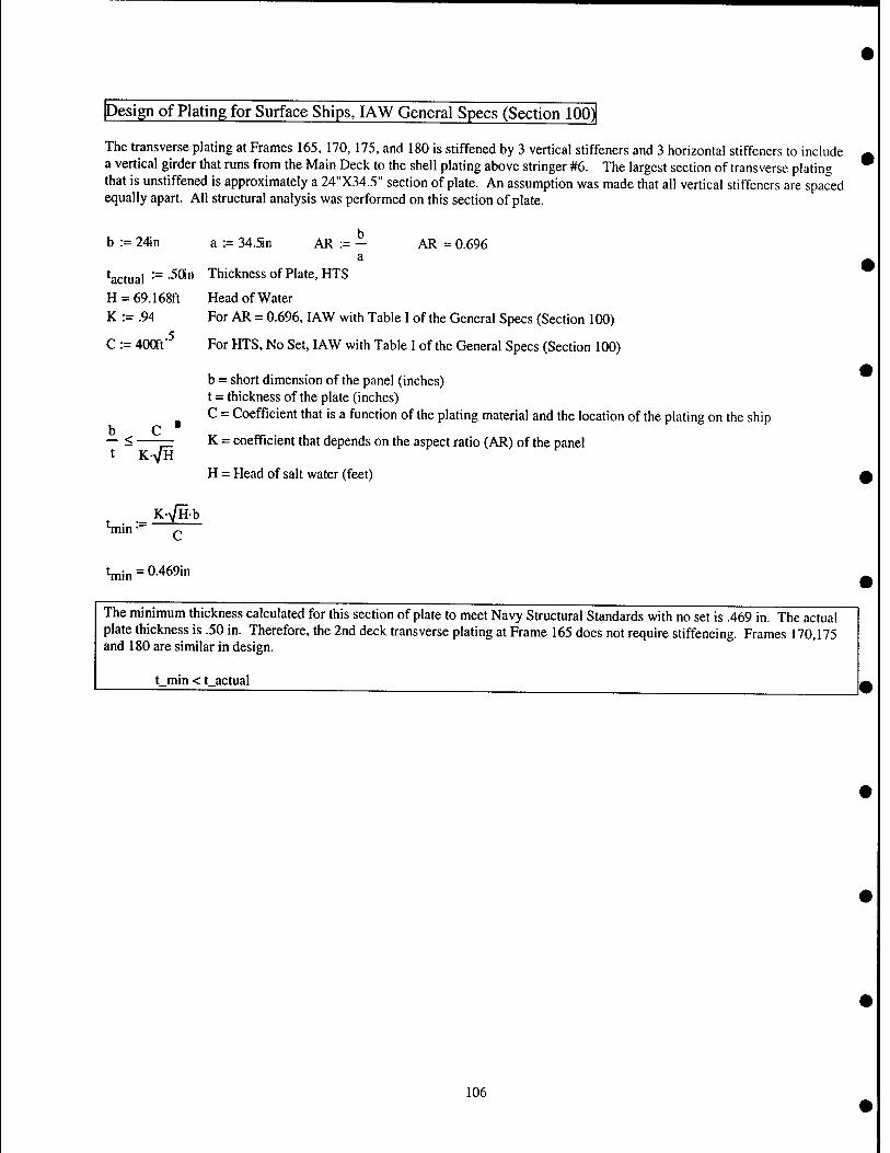
Design of Plating for Surface Ships, lAW General Specs (Section 100)|
The transverse plating at Frames 165, 170, 175, and 180 is stiffened by 3 vertical stiffeners and 3 horizontal stiffeners to include a vertical girder that runs from the Main Deck to the shell plating above stringer #6. The largest section of transverse plating that is unstiffened is approximately a 24"X34.5" section of plate. An assumption was made that all vertical stiffeners are spaced equally apart. All structural analysis was performed on this section of plate.
b := 24in a := 34.Sn AR := - AR = 0.696 a
Wual •= •^^" Thickness of Plate, HTS
H = 69.168ft Head of Water K := .94 For AR = 0.696, lAW with Table I of the General Specs (Section 100)
C := 400ft"^ For HTS, No Set, lAW with Table I of the General Specs (Section 100)
b = short dimension of the panel (inches) t = thickness of the plate (inches) C = Coefficient that is a function of the plating material and the location of the plating on the ship
K = coefficient that depends on the aspect ratio (AR) of the panel
H = Head of salt water (feet)
b — <■
K-VH
t • •= — min • p
t^i„ = 0.469in
The minimum thickness calculated for this section of plate to meet Navy Structural Standards with no set is .469 in. The actual plate thickness is .50 in. Therefore, the 2nd deck transverse plating at Frame 165 does not require stiffening. Frames 170,175 and 180 are similar in design.
t_min<t actual
106
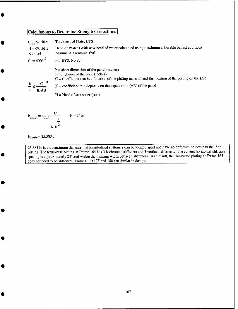
Calculations to Determine Strength Corrections
t ■ := .Sttn Thickness of Plate, HTS
H = 69.168ft Head of Water (With new head of water calculated using maximum allowable ballast addition) K := .94 Assume AR remains .696
C := 40Qft'^ For HTS, No Set
b = short dimension of the panel (inches) t = thickness of the plate (inches) C = Coefficient that is a function of the plating material and the location of the plating on the ship
b C " — < K = coefficient that depends on the aspect ratio (AR) of the panel K-VH
''limit- '•mm j
KH^
''limit = = 25.583in
H = Head of salt water (feet)
24in
25.583 in is the maximum distance that longitudinal stiffeners can be located apart and have no deformation occur to the .5 in plating. The transverse plating at Frame 165 has 3 horizontal stiffeners and 3 vertical stiffeners. The current horizontal stiffener spacing is approximately 24" and within the limiting width between stiffeners. As a result, the transverse plating at Frame 165 does not need to be stiffened. Frames 170,175 and 180 are similar in design.
107
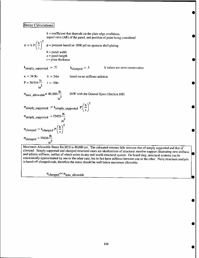
Stress Calculations:
b^2
k = coefficient that depends on the plate edge conditions, aspect ratio (AR) of the panel, and position of point being considered
a := k-Pl — I p = pressure based on 1000 psf on sponson shell plating
b = panel width a = panel length t = plate thickness
'Siniply_supported '■= ■'^- "^lamped •= -^ ^ ^^'"^^ ^""^ "1°^' conservative
a := 34.Sn b := 24in based on no stiffener addition
P = 30.934— t := .SOn . 2 in
*^max_allowable~ 40,000— I AW with the General Specs (Section 100) 2
in
^simply_supported ' *Simply_supported '^l
'^simply_supported ~ "o
b^2
... b ^clamped " '^clamped
^clamped = 35636-^ in
in
2
Maximum Allowable Stress for HTS is 40,000 psi. The calcuated stresses falls between that of simply supported and that of clamped. Simply supported and clamped structural cases are idealizations of structural member support illustrating zero stiffness and infinite stiffness, neither of which exists in any real-world structural system. On board ship, structural systems can be conveniently approximated by one or the other case, but in fact have stiffness between one or the other. Navy structural analysis is based off clamped ends, therefore the stress should be well below maximum allowable.
'^clamped*^'^ ^max_allowabl(
108
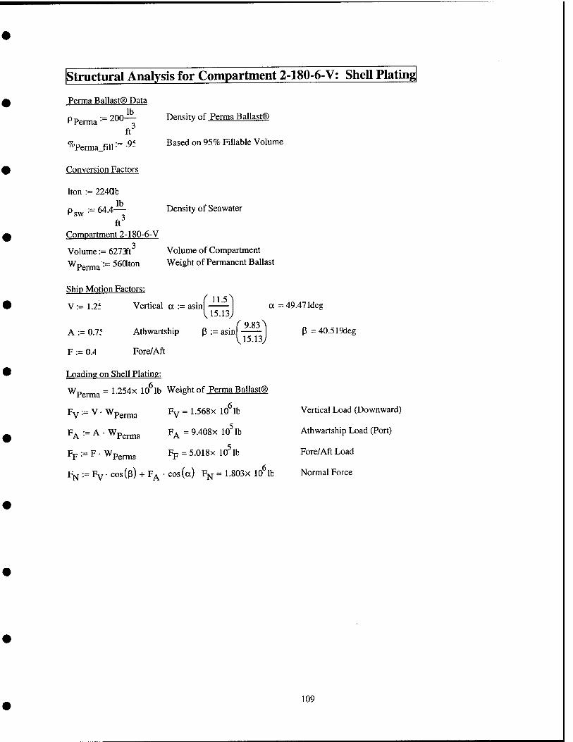
structural Analysis for Compartment 2-180-6-V: Shell Plating
Perma Ballast® Data
PPerma^=200-^ ft
^"Perma_fill •= •^-
Conversion Factors
Iton := 224ab
Density of Perma Ballast®
Based on 95% Fillable Volume
'sw : 64.4 lb
ft Compartment 2-180-6-V
Volume := 6272ft^ Wperma==56aton
Density of Seawater
Volume of Compartment Weight of Permanent Ballast
Ship Motion Factors:
V := 1.2f Vertical a := asin r n.5
15.13 a = 49.47 Ideg
A := 0.7f
F := 0.4
Athwartship
Fore/Aft
P := asin f 9.83
15.13
Loading on Shell Plating:
Wperma = ^■254x 10^ lb Weight of Perma Ballast®
Fy := V • Wpgrma Fv=1.568x 10 lb
F^ =9.408x 10^ lb
Fp = 5.018x 10^ lb
F^ :- A • Wpgj.j^g
Fp := F • Wpgj.jjjg
F^ := Fy • cos(p) + F^ ■ cos(a) Fj^ = 1.803x 10^lb
P =40.519deg
Vertical Load (Downward)
Athwartship Load (Port)
Fore/Aft Load
Normal Force
109
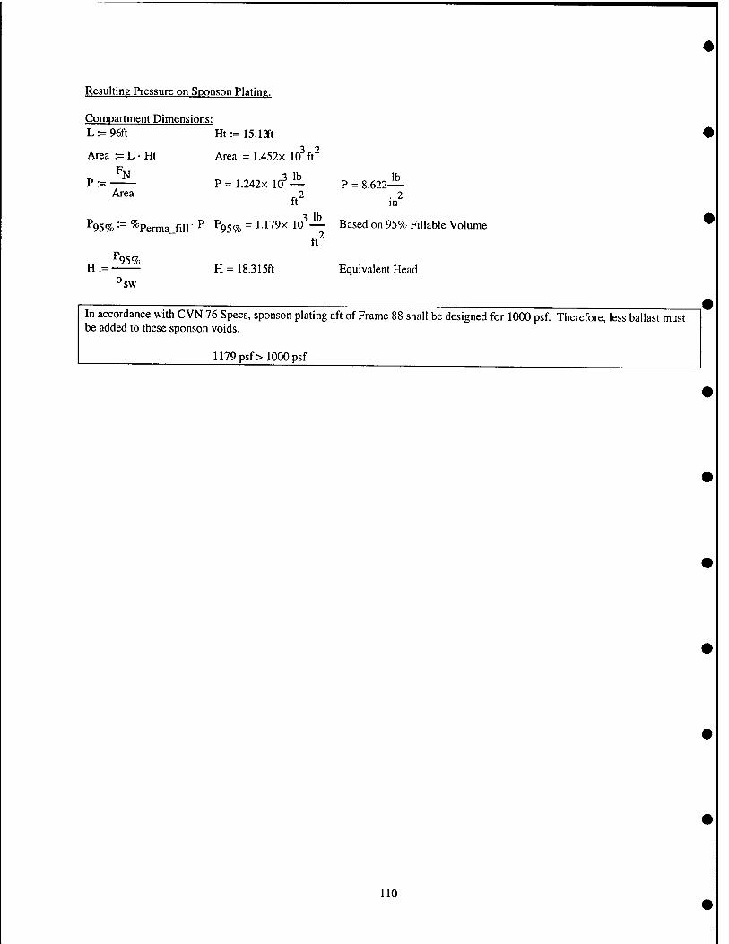
Resulting Pressure on Sponson Plating:
Compartment Dimensions: L:=96ft Ht:= 15.13ft
Area := L • Ht Area = 1.452x 10^ ft^ p
P := P = 1.242x 10^ — P = 8.622— Area 2 .2
It m
^95% -"^ %erma_fill' ^ ^95% = ^ •179x 10 — Based on 95% Fillable Volume ft^
^95% H := H = 18.315ft Equivalent Head
Psw
In accordance with CVN 76 Specs, sponson plating aft of Frame 88 shall be designed for 1000 psf. Therefore, less ballast must be added to these sponson voids.
1179 psf > 1000 psf
110
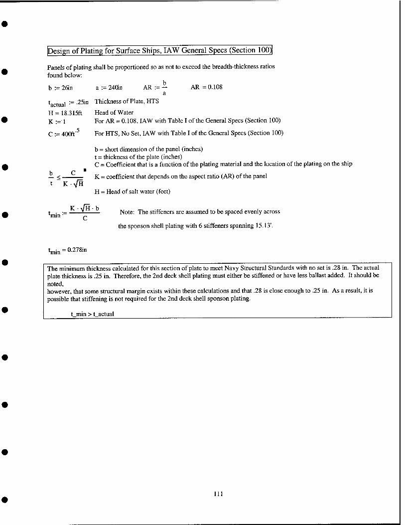
Design of Plating for Surface Ships, lAW General Specs (Section 100)
Panels of plating shall be proportioned so as not to exceed the breadth-thickness ratios found below:
b := 26in a := lidn AR := - AR =: 0.108 a
^actual '•= -251" Thickness of Plate, HTS
H = 18.315ft Head of Water K := 1 For AR = 0.108, lAW with Table I of the General Specs (Section 100)
C := 400ft'^ For HTS, No Set, lAW with Table I of the General Specs (Section 100)
b = short dimension of the panel (inches) t = thickness of the plate (inches) C = Coefficient that is a function of the plating material and the location of the plating on the ship
b C ■ — < K = coefficient that depends on the aspect ratio (AR) of the panel t K-VH
H = Head of salt water (feet)
l^.^ ■- —12t—'.— Note: The stiffeners are assumed to be spaced evenly across
the sponson shell plating with 6 stiffeners spanning 15.13'.
"^imn Q
t^„ = 0.278in
The minimum thickness calculated for this section of plate to meet Navy Structural Standards with no set is .28 in. The actual plate thickness is .25 in. Therefore, the 2nd deck shell plating must either be stiffened or have less ballast added. It should be noted, however, that some structural margin exists within these calculations and that .28 is close enough to .25 in. As a result, it is possible that stiffening is not required for the 2nd deck shell sponson plating.
t min > t actual
111
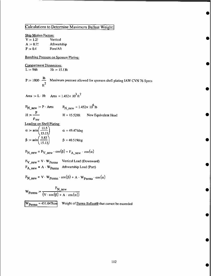
Calculations to Determine Maximum Ballast Weight:
Ship Motion Factors: V:=1.2f Vertical A := 0.7; Athwartship F := O.A Fore/Aft
Resulting Pressure on Sponson Plating:
Compartment Dimensions: L:=9fft Ht:=15.1Jt
P := 1000- — Maximum pressure allowed for sponson shell plating lAW CVN 76 Specs ft^
Area := L • Ht Area = 1.452x 10^ ft^
%_new ■■= P • Area F^^gw = 1 •452x 10^ lb
P H := H = 15.528ft New Equivalent Head
Psw Loading on Shell Plating:
f 11.5 1 ■ a := asin a = 49.47 Ideg U5.13J
3:=asin^- P=40.519deg
%_new = Fv_new ' cos(p) + F^_„g^ • cos (a)
^V_new = ^ ■ ^Perma Vertical Load (Downward)
'^Ajew - A ■ ^Perma Athwartship Load (Port)
%_new = V • Wperma • cos(3) + A • Wpg^ia " cos (a)
N_new
P^™^^^(v.cos(p) + A.cos(a))
^Perma ~ ^^ ^ ■0471tor Weight of Perma Ballast® that cannot be exceeded
112
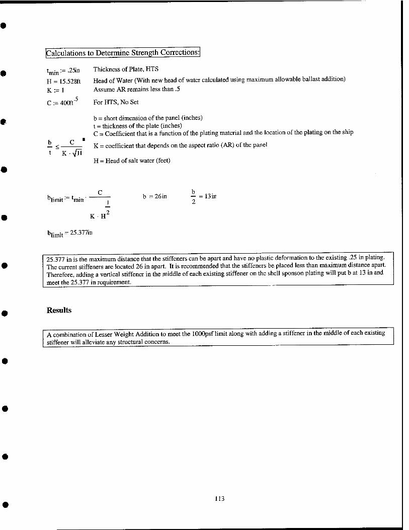
Calculations to Determine Strength Corrections:!
25in Thickness of Plate, HTS ■^min"
H = 15.528ft K:=l
C := 400ff^
b — < K yfU
Head of Water (With new head of water calculated using maximum allowable ballast addition)
Assume AR remains less than .5
For HTS, No Set
b = short dimension of the panel (inches) t = thickness of the plate (inches) C = Coefficient that is a function of the plating material and the location of the plating on the ship
K = coefficient that depends on the aspect ratio (AR) of the panel
H = Head of salt water (feet)
limit ■ min'
K • H
b = 26in - = Bin 2
blimit = 25.377in
25.377 in is the maximum distance that the stiffeners can be apart and have no plastic deformation to the existing .25 in plating. The current stiffeners are located 26 in apart. It is recommended that the stiffeners be placed less than maximum distance apart. Therefore, adding a vertical stiffener in the middle of each existing stiffener on the shell sponson plating will put b at 13 in and meet the 25.377 in requirement.
Results
A combination of Lesser Weight Addition to meet the lOOOpsf limit along with adding a stiffener in the middle of each existing stiffener will alleviate any structural concerns.
113
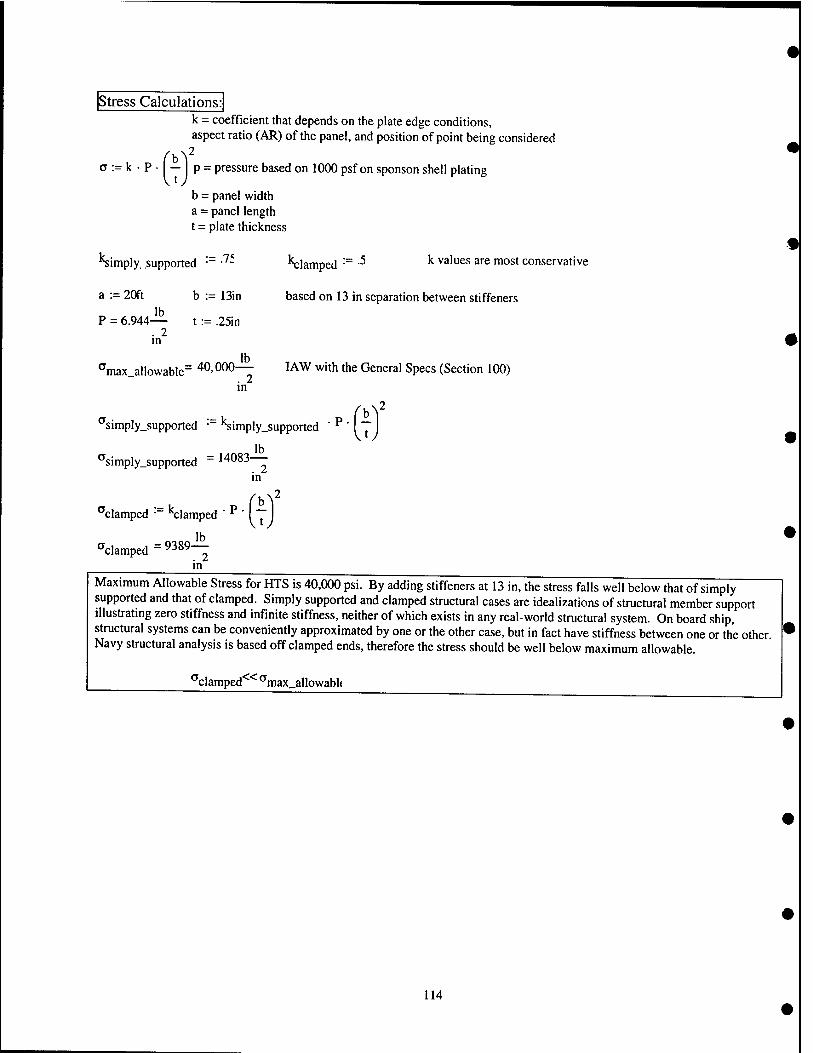
Stress Calculations: k = coefficient that depends on the plate edge conditions, aspect ratio (AR) of the panel, and position of point being considered
a := k • P • — p = pressure based on 1000 psf on sponson shell plating
b = panel width a = panel length t = plate thickness
'^imply_supported •= •'^- K;laniped •= -^ ^ ^^'"^^ ^""^ ""o^t conservative
a := 20ft b := 13in based on 13 in separation between stiffeners
P = 6.944— t := .25in . 2 in
°max_allowable'= 40,000— lAW with the General Specs (Section 100) in
"'simply_supported •" 'Simply_supported ' '^ ' I T I
^simply_supported ~ 14083— in
'^clamped • "^clamped ' ^ ' '
^clamped =9389-!^
in
Maximum Allowable Stress for HTS is 40,000 psi. By adding stiffeners at 13 in, the stress falls well below that of simply supported and that of clamped. Simply supported and clamped structural cases are idealizations of structural member support illustrating zero stiffness and infinite stiffness, neither of which exists in any real-world structural system. On board ship, structural systems can be conveniently approximated by one or the other case, but in fact have stiffness between one or the other. Navy structural analysis is based off clamped ends, therefore the stress should be well below maximum allowable.
''clamped^^^max.allowabU
114
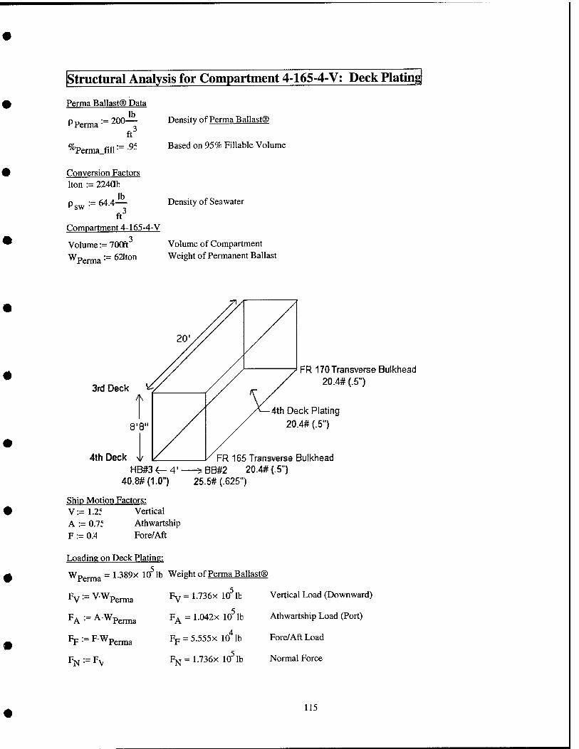
structural Analysis for Compartment 4-165-4-V; Deck Plating
Perma Ballast® Data
Pperma
^^Perma fill
200^ 3
ft" :=.9f
Conversion Factors Iton := 224ab
sw ■ 64.4^
ft^
Density of Perma Ballast®
Based on 95% Fillable Volume
Compartment 4-165-4-V
Volume :=700ft^ Wpenna==621ton
Density of Seawater
Volume of Compartment Weight of Permanent Ballast
3rd Deck
4th Deck
FR 170 Transverse Bulkhead 20.M{.5")
8'8"
HB#3 4-4'- 40.8#(1.0") 25.5#{.625")
4th Deck Plating 20.4# (.5")
FR 165 Transverse Bulkhead BB#2 20.4#(-5")
Ship Motion Factors: V:=1.2f Vertical A := 0.7f Athwartship F := 0.4 Fore/Aft
Loading on Deck Plating:
Wperma = 1-389x10'lb Weight of Perma Ballast®
Fv^=V.Wp,^3 Fy=1.736x lo'lb
FA ■■= AWpenna F^ = 1.042x lo'lb
Fp := FWp^j^g Fp = 5.555x lo'^lb
% •= Fv Fi>j = 1.736x lo'lb
Vertical Load (Downward)
Athwartship Load (Port)
Fore/Aft Load
Normal Force
115

Resulting Pressure on Deck Plating:
Compartment Dimensions: L := 20ft W := 4ft
Area := LW Area = 80ft^
P:=^ P.ZnxlO^i^ P = 15.06^ Area ^2 .2
It m
^^95% '-"^ ^"Perma.fiir^ ^95% = ^^O^x lo'^— Based on 95% Fillable Volume m
^95% H := H = 32.011ft Equivalent Head
Psw
The actual head for flooding of the 4th deck to the 6" above the 2nd deck (DC Deck) will result in a head of 27.7'. This value is below the head calculated above of 32'. As a result, the deck plating must be stiffened.
32 ft > 27.7 ft
116
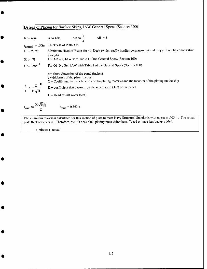
Design of Plating for Surface Ships, lAW General Specs (Section 100)
b := 48in a := 48in AR:=^ AR =1
^actual H := 27.7ft
K := .78
C := 35Qft
- .5Qiii Thickness of Plate, OS
Maximum Head of Water for 4th Deck (which really implies permanent set and may still not be conservative enough) For AR = 1, lAW with Table I of the General Specs (Section 100)
For OS, No Set, lAW with Table I of the General Specs (Section 100) .5
b — < K-VH
b = short dimension of the panel (inches) t = thickness of the plate (inches) C = Coefficient that is a function of the plating material and the location of the plating on the ship
K = coefficient that depends on the aspect ratio (AR) of the panel
H = Head of salt water (feet)
K-VHb min" tmin = 0-563in
The minimum thickness calculated for this section of plate to meet Navy Structural Standards with no set is .563 in. The actual plate thickness is .5 in. Therefore, the 4th deck shell plating must either be stiffened or have less ballast added.
t_min »t_actual
117
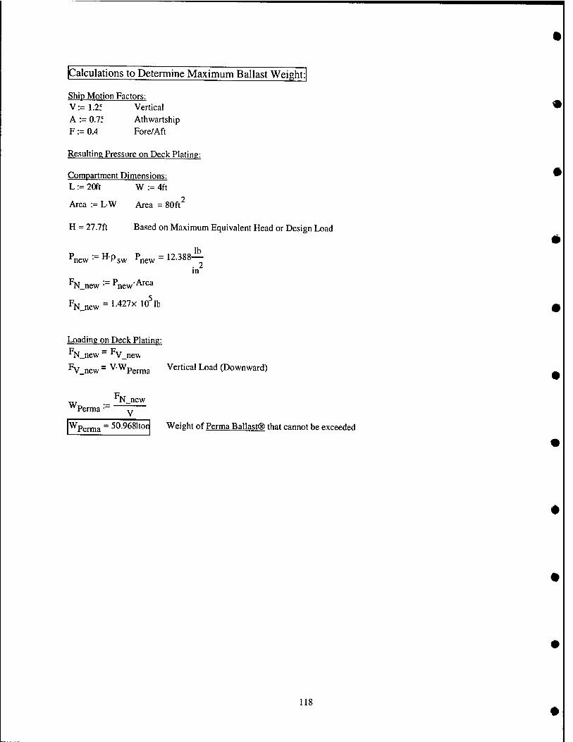
Calculations to Determine Maximum Ballast Weight:]
Ship Motion Factors: V:=1.2f Vertical A :- 0.11 Atiiwartship F := O.A Fore/Aft
Resulting Pressure on Deck Plating:
Compartment Dimensions: L := 20ft W := 4ft
Area := L-W Area = 80ft^
H = 27.7ft Based on Maximum Equivalent Head or Design Load
^new '■' ^'Psw ^new ~ 12.388— in
%_new ■" ^new'^^^
pN_new = 1-427x10^ lb
Loading on Deck Plating: F — F N_new ~ ^V_new
^V new ~ ^"^Perma Vertical Load (Downward)
^Perma '■- N_new
V
^Perma ~ 50.9681tor Weight of Perma Ballast® that cannot be exceeded
118
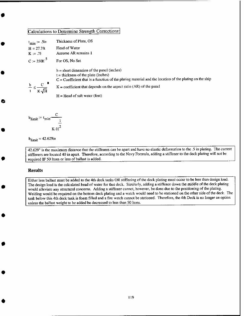
Calculations to Determine Strength Corrections:
tjni„:=.5in Thickness of Plate, OS
H = 27.7ft Head of Water
K - .78 Assume AR remains 1
C := 350ft'^ For OS, No Set
b — < •
K-VH
b = short dimension of the panel (inches) t = thickness of the plate (inches) C = Coefficient that is a function of the plating material and the location of the plating on the ship
K = coefficient that depends on the aspect ratio (AR) of the panel
H = Head of salt water (feet)
limit • ^min"
KH
^limit'' ■■ 42.629in
42.629" is the maximum distance that the stiffeners can be apart and have no elastic deformation to the .5 in plating. The current stiffeners are located 40 in apart. Therefore, according to the Navy Formula, adding a stiffener to the deck plating will not be required IF 50 Itons or less of ballast is added.
Results
Either less ballast must be added to the 4th deck tanks OR stiffening of the deck plating must occur to be less than design load. The design load is the calculated head of water for that deck. Similarly, adding a stiffener down the middle of the deck plating would alleviate any structural concerns. Adding a stiffener cannot, however, be done due to the positioning of the plating. Welding would be required on the bottom deck plating and a watch would need to be stationed on the other side of the deck. The tank below this 4th deck tank is foam filled and a fire watch cannot be stationed. Therefore, the 4th Deck is no longer an option unless the ballast weight to be added be decreased to less than 50 Itons.
119

Stress Calculations: No Stiffening
CT := kP- -
k = coefficient that depends on the plate edge conditions, aspect ratio (AR) of the panel, and position of point being considered
p = pressure based on 50 Itons of ballast addition
b = panel width a = panel length t = plate thickness
'^imply_supported ■" ■'- a := 20ft
Pnew = 12-388-!^ in
"niax_allowable= 28,000— in
'^lamped " " ^ values are most conservative
b :- 48in based on no stiffener addition
t := .5in
I AW with the General Specs (Section 100)
,2
*^simply_supported ' "Simply.supported '^new /i
U
^simply_supported ~ 85626— in
^clamped • '^clamped'^newi j
«^clamped= 57084- Jb_ . 2 in
Maximum Allowable Stress for OS is 28,000 psi. If no stiffeners are added, the calculated stress is much greater than maximum allowable stress. As a result, stiffeners must still be added to be less than the maximum allowable stress (even with less ballast added and based off design load using maximum head of water).
^clamped'^^^max_allowabl<
120
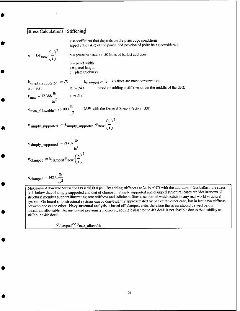
Stress Calculations: Stiffening
a := kP, new
k = coefficient that depends on the plate edge conditions, aspect ratio (AR) of the panel, and position of point being considered
p = pressure based on 50 Itons of ballast addition
b = panel width a = panel length t = plate thickness
k . , _^ j •= 7' k_i j •= .5 k values are most conservative Nimply_supported • ■'- "^jlamped a .- 20ft b :- 24ir based on adding a stiffener down the nviddle of the deck
Pnew = 12.388^ in
t := .5in
lb a II ui = 28 000— lAW with the General Specs (Section 100) max_allowable -^"'""^ ^ t- v ^
in
^simply_supported • 'Simply_supported '^newl ^
^simply_supported = 21407— . 2 in
^clamped • Clamped newl ^
clamped 14271 lb
m Maximum Allowable Stress for OS is 28,000 psi. By adding stiffeners at 24 in AND with the addition of less ballast, the stress falls below that of simply supported and that of clamped. Simply supported and clamped structural cases are idealizations of structural member support illustrating zero stiffness and infinite stiffness, neither of which exists in any real-world structural system. On board ship, structural systems can be conveniently approximated by one or the other case, but in fact have stiffness between one or the other. Navy structural analysis is based off clamped ends, therefore the stress should be well below maximum allowable. As mentioned previously, however, adding ballast to the 4th deck is not feasible due to the inability to stiffen the 4th deck.
^clamped ^max_allowabl(
121
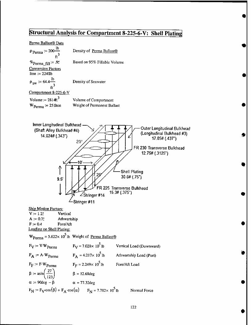
structural Analysis for Compartment 8-225-6-V; Shell Plating
Perma Ballast® Data
PPerma:=2{)0-!^
ft
^''Perma_fill •= ■^~ Conversion Factors Iton := 224ab
lb sw 64.4-
ft" Compartment 8-225-6-V
Volume := 28 l^t^
Wperma '■= 2511ton
Density of Perma Ballast®
Based on 95% Fillable Volume
Density of Seawater
Volume of Compartment Weight of Permanent Ballast
Inner Longitudinal Bulkhead (Shaft Alley Bulkhead #4)
14.024# (.343")
Outer Longitudinal Bulkhead / (Longitudinal Bulkhead #3)
'^ 17.85# (.437")
FR 230 Transverse Bulkhead 12.75# (.3125")
\A^s -^ ^stringer #14
^Stringer #11
Ship Motion Factors: V:=1.2f Vertical A := 0.7i Athwartship F := 0.4 Fore/Aft leading on Shell Plating:
^Perma = 5.622x 10^ lb Weight of Perma Ballast®
Plating (.75")
FR 225 Transverse Bulkhead 15.3# (.375")
Pv^=V.Wp,^3
FA==A-Wp,^3
Fp := FWp^^g
R • ("27 p := asm
U23. a := 90deg - P
Fv = 7.028x 10 lb
F^ =4.217x 10^ lb
Fp=2.249x 10^ lb
P = 12.68deg
a = 77.32deg
Vertical Load (Downward)
Athwartship Load (Port)
Fore/Aft Load
Fi^:=Fvcos(p) + F^-cos(a) Fj^j = 7.782x lO^lb Normal Force
122
Resulting Pressure on Shell Plating:
Compartment Dimensions: L := 20ft Ht := 12Sn
Area := L-Hl Area = 205ft^
% 3 lb lb P :=:: —^ P = 3.796X 10 — P = 26.363—
Area .2 . 2 ft m - It-
^95% ■= ^"Perma.fiir'f' ^95% " ^-^^^^ ^^ — ^^^^^ °" ^^^^ ^^^^^^^^ Volume ft^
^9'5% H := —^ H = 56ft Equivalent Head
Psw
123

Design of Plating for Surface Ships, lAW General Specs (Section 100)
b:=41in a := 24an AR := - AR =0.171 a
'actual :=-^Sin Thickness of Plate, HTS
H = 56ft Head of Water K := 1 For AR = 0.171, lAW with Table I of the General Specs (Section 100)
C := 400ft' For HTS, No Se, lAW with Table I of the General Specs (Section 100)t
b = short dimension of the panel (inches) t = thickness of the plate (inches) C = Coefficient that is a function of the plating material and the location of the plating on the ship
— ^ = K = coefficient that depends on the aspect ratio (AR) of the panel t KVH
H = Head of salt water (feet)
K-VHb 'min • C
t„i„ = 0.767in
The minimum thickness calculated for this section of plate to meet Navy Structural Standards with no set is .767 in. The actual plate thickness is .75 in. Therefore, the 8th deck shell plating must either be stiffened or have less ballast added.
t_min »t actual
124
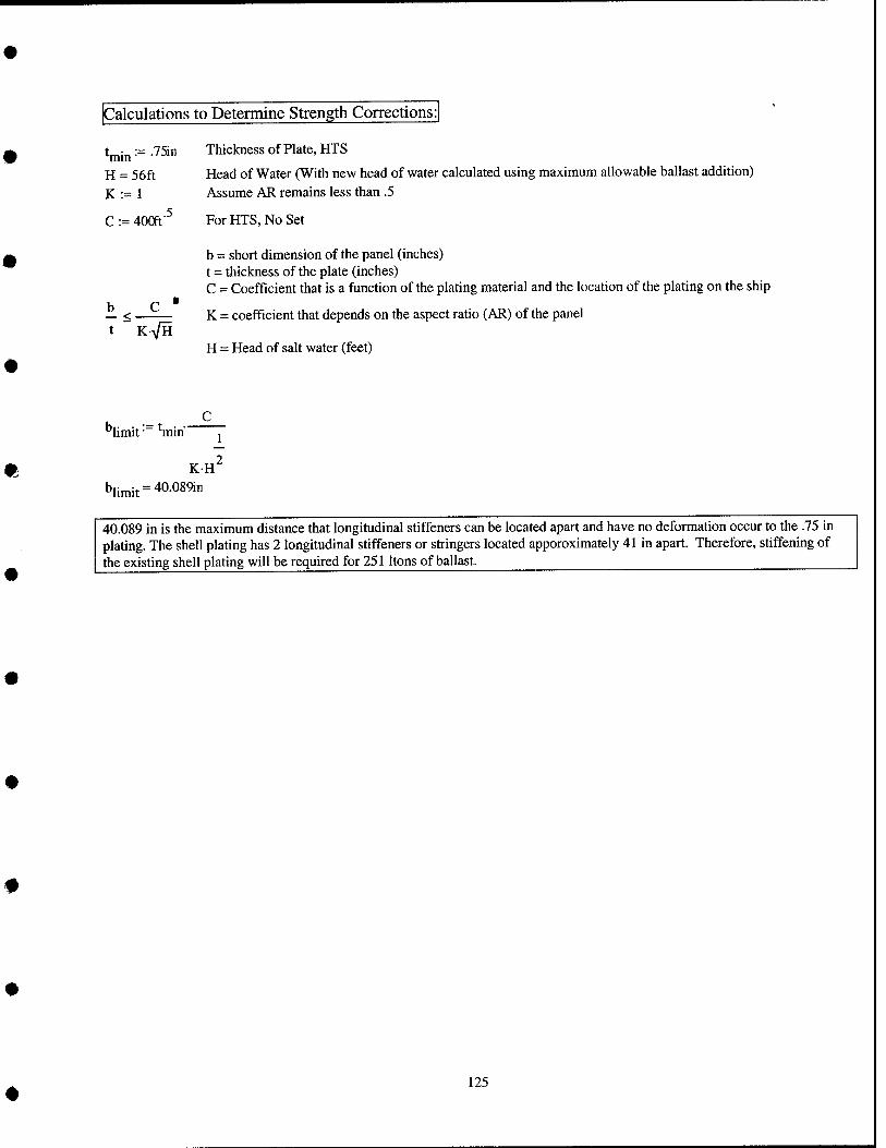
Calculations to Determine Strength Corrections:!
t ■ -.75in Thickness of Plate, HTS
H = 56ft Head of Water (With new head of water calculated using maximum allowable ballast addition) K := 1 Assume AR remains less than .5
C := 400ft'^ For HTS, No Set
b = short dimension of the panel (inches) t = thickness of the plate (inches) C = Coefficient that is a function of the plating material and the location of the plating on the ship
b C ■ _ < K = coefficient that depends on the aspect ratio (AR) of the panel K-y/H
"limit • ^min
KH blimit = 40-08911,
H = Head of salt water (feet)
C
40.089 in is the maximum distance that longitudinal stiffeners can be located apart and have no deformation occur to the .75 in plating. The shell plating has 2 longitudinal stiffeners or stringers located apporoximately 41 in apart. Therefore, stiffening of the existing shell plating will be required for 251 Itons of ballast.
125
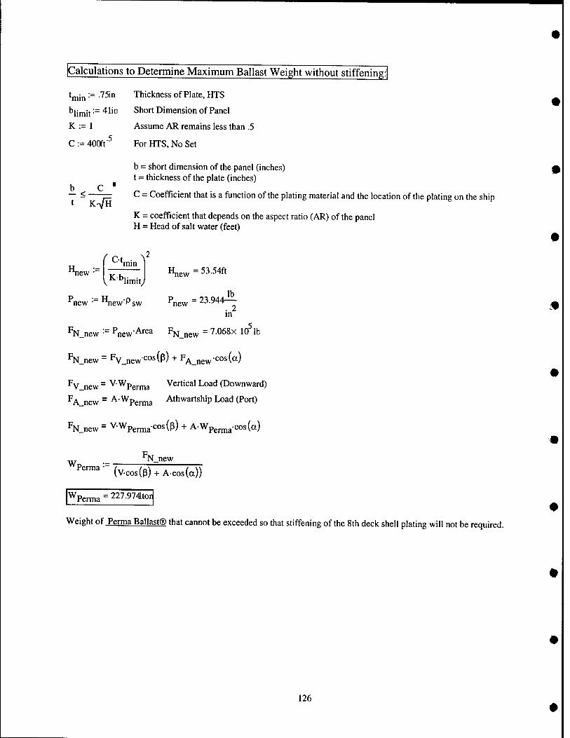
Calculations to Determine Maximum Ballast Weight without stiffening:
trnin := .75in Thickness of Plate, HTS min b|jjjjjj := 41in Short Dimension of Panel
K := 1 Assume AR remains less than .5 .5
C := 400ft' For HTS, No Set
b — < t K>/H
b = short dimension of the panel (inches) t - thickness of the plate (inches)
C = Coefficient that is a function of the plating material and the location of the plating on the ship
K = coefficient that depends on the aspect ratio (AR) of the panel H = Head of salt water (feet)
Hn^ lew • f Ct ■ \ min
^^^■''limity H„e^= 53.54ft
Pnew ■= HnewPsw ^new = 23.944^ in
N new • *^new ■•= Pnp,.,Area F, N new =7.068x 10 lb
%_new = Fv_new-'^°s(p) + F^jg^-cosCa)
'^V new ~ ^'^Perma Vertical Load (Downward)
'^A.new ~ ^'^Perma Athwartship Load (Port)
%_new = VWpern,aCos(p) + A-Wpern,a-cos(a)
W N_new Perma
(Vcos(p) + A-cos(a))
Wperma=227.9741ton
Weight of Perma Ballast® that cannot be exceeded so that stiffening of the 8th deck shell plating will not be required.
126
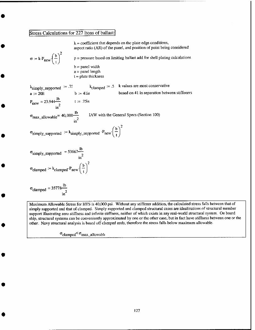
Stress Calculations for 227 Itons of ballast:
k = coefficient that depends on the plate edge conditions, aspect ratio (AR) of the panel, and position of point being considered
P ._ y^.p -I — I p = pressure based on limiting ballast add for shell plating calculations new , j
b = panel width a = panel length t = plate thickness
1c . , _ j •= 7' L.1 „ j •= .5 k values are most conservative •^imply.supported • •'- "xlamped a := 20ft b := 41in based on 41 in separation between stiffeners
Pnew=23.944i^ t := .75ii, in
^max allowable= ^^' ^^— ^^^ ^'^'^ *^ General Specs (Section 100) in
b^^ '^simply_supported • 'Simply_supported '^newl j.
'^simply_supported -53667 ^ in
,b^2 ^clamped ■ clamped new"! ^
f^clamped = 35778— in
Maximum Allowable Stress for HTS is 40,000 psi. Without any stiffener addition, the calculated stress falls between that of simply supported and that of clamped. Simply supported and clamped structural cases are idealizations of structural member support illustrating zero stiffness and infinite stiffhess, neither of which exists in any real-world structural system. On board ship, structural systems can be conveniently approximated by one or the other case, but in fact have stiffness between one or the other. Navy structural analysis is based off clamped ends, therefore the stress falls below maximum allowable.
^clamped*^ ''max_allowabl<
127
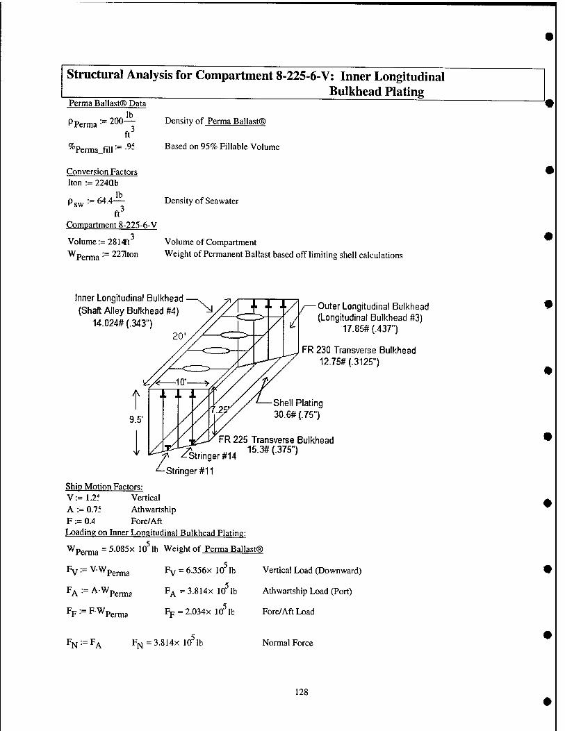
structural Analysis for Compartment 8-225-6-V: Inner Longitudinal Bulkhead Plating
Perma Ballast® Data lb
PP, erma := 200- ft"
hernia filb^^-
Density of Perma Ballast®
Based on 95% Fillable Volume
Conversion Factors Iton := 224ab
lb sw 64.4-
ft Compartment 8-225-6-V
Volume := 281'tft"'
Wperma '■= 2271ton
Density of Seawater
Volume of Compartment Weight of Permanent Ballast based off limiting shell calculations
Inner Longitudinal Bulkhead (Shaft Alley Bulkhead #4)
14.024# (.343 20
Outer Longitudinal Bulkhead A (Longitudinal Bulkhead #3)
^ 17.85# (.437")
FR 230 Transverse Bulkhead 12.75# (.3125")
-Stringer #14
FR 225 Transverse Bulkhead 15.3# (.375"
Z_c Stringer #11
Ship Motion Factors: V:=1.2f Vertical A := 0.7f Athwartship F := 0.4 Fore/Aft Loading on Inner Longitudinal Bulkhead Plating:
^Perma = 5.085x 10^ lb Weight of Perma Ballast®
Fv^^VWp^^^
FA -■= AWperma
FP ■■= FWpenna
FY=:6.356X 10 lb
F^ =3.814x 10^ lb
Fp = 2.034x 10^ lb
Vertical Load (Downward)
Athwartship Load (Port)
Fore/Aft Load
r^j: Fi^=3.814x 10 lb Normal Force
128
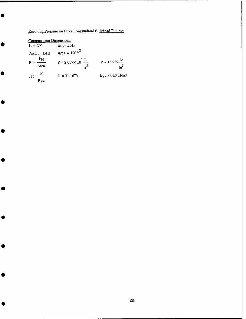
Resulting Pressure on Inner Longitudinal Bulkhead Plating:
Compartment Dimensions: L:=20ft Ht:=114n
Area := L-Ht Area = 190ft^
% 3 lb lb P •= —^ P = 2.007X 10 — P = 13.939—
Area ^2 .2
p H := —— H = 31.167ft Equivalent Head
Psw
129

Design of Plating for Surface Ships, lAW General Specs (Section 100)
b := 48in a := 114)n AR := — AR = 0.421 a
^actual :=-34311 Thickness of Plate, HTS
H = 31.167ft Head of Water K := 1 For AR = 0.421,1 AW with Table I of the General Specs (Section 100)
C := 400ft' For HTS, No Set, lAW with Table I of the General Specs (Section 100)
b = short dimension of the panel (inches) t = thickness of the plate (inches) C = Coefficient that is a function of the plating material and the location of the plating on the ship
K = coefficient that depends on the aspect ratio (AR) of the panel
H = Head of salt water (feet)
b — < • K-VH
K-VH-b t„:„ := — mm"
^min = 0-67in
The 8th deck inner longitudinal bulkhead (Shaft Alley Bulkhead #4) currently has 4 vertical stiffeners spaced 4 ft apart. The minimum thickness calculated for this section of plate to meet Navy Structural Standards with no set is .67 in. The actual plate thickness is .343 in. Therefore, the 8th deck inner longitudinal bulkhead plating must be stiffened.
t_min »t actual
130
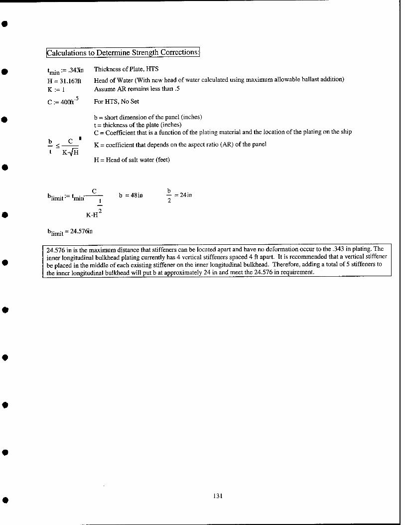
Calculations to Determine Strength Corrections:
tj„i„:= .34311
H = 31.167ft K:= 1
C := 400ft'^
i<. K-VH
Thickness of Plate, HTS
Head of Water (With new head of water calculated using maximum allowable ballast addition) Assume AR remains less than .5
For HTS, No Set
b = short dimension of the panel (inches) t = thickness of the plate (inches) C = Coefficient that is a function of the plating material and the location of the plating on the ship
K - coefficient that depends on the aspect ratio (AR) of the panel
H = Head of salt water (feet)
'limit := t mm
KH
:48in b - = 24in 2
blimit=24.576in
24.576 in is the maximum distance that stiffeners can be located apart and have no deformation occur to the .343 in plating. The inner longitudinal bulkhead plating currently has 4 vertical stiffeners spaced 4 ft apart. It is recommended that a vertical stiffener be placed in the middle of each existing stiffener on the inner longitudinal bulkhead. Therefore, adding a total of 5 stiffeners to the inner longitudinal bulkhead will put b at approximately 24 in and meet the 24.576 in requirement.
131
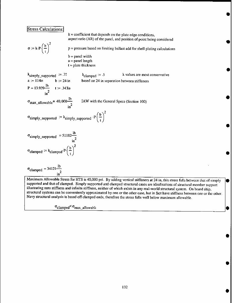
Stress Calculations:
a := kPl -
k = coefficient that depends on the plate edge conditions, aspect ratio (AR) of the panel, and position of point being considered
p - pressure based on limiting ballast add for shell plating calculations
b = panel width a = panel length t = plate thickness
Simply_supported '■" •^- a := 114in b := 24-in
P = 13.939^ t := .343in . 2 in
lb ^max_allowable= 40,000—
in
:= k.;.
''clamped •" -^ ^ values are most conservative
based on 24 in separation between stiffeners
lAW with the General Specs (Section 100)
,2
^simply_supported • '^simply_supported .P.i^
lb *'simply_supported 51182 . 2
m
■'clamped ■ "Clamped'"I I
clamped 34121-!^ . 2 m
Maximum Allowable Stress for HTS is 40,000 psi. By adding vertical stiffeners at 24 in, this stress falls between that of simply supported and that of clamped. Simply supported and clamped structural cases are idealizations of structural member support illustrating zero stiffness and infinite stiffness, neither of which exists in any real-world structural system. On board ship, structural systems can be conveniently approximated by one or the other case, but in fact have stiffness between one or the other. Navy structural analysis is based off clamped ends, therefore the stress falls well below maximum allowable.
1<CT, clamped "max_allowabl(
132
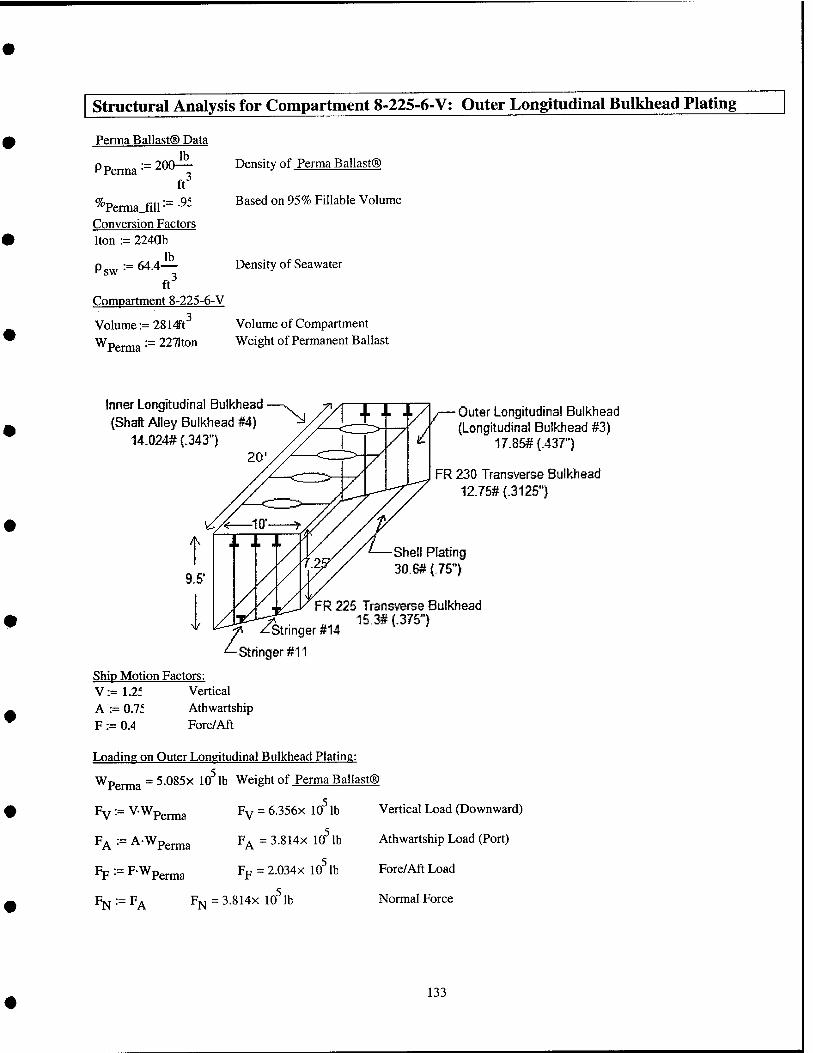
structural Analysis for Compartment 8-225-6-V; Outer Longitudinal Bulkhead Plating
Perma Ballast® Data lb
PP, 'erma ■ 200-
% Pema fill •
ft 9f
Conversion Factors Iton := 224ab
sw 64.4^^
ft^ Compartment 8-225-6-V
Volume := 2814Ft^ Wperma:=2271ton
Density of Perma Ballast®
Based on 95% Fillable Volume
Density of Seawater
Volume of Compartment Weight of Permanent Ballast
Inner Longitudinal Bulkhead (Shaft Alley Bulkhead #4}
14.024# (.343") 20
Outer Longitudinal Bulkhead (Longitudinal Bulkhead #3)
17.8S# (.437")
FR 230 Transverse Bulkhead 12.7^ (.3125")
Shell Plating 30.6#(.751
FR 225 Transverse Bulkhead ^.. 15.3#{.3751
-Stnnger #14
Ship Motion Factors: V:=1.2f Vertical A := 0.7f Athwartship F := 0.4 Fore/Aft
Loading on Outer Longitudinal Bulkhead Plating:
Wpg,^a = 5.085x lO^lb Weight of Perma Ballast®
Fv:=V.Wp,^3
F^ := AWpg^a
Fp := F-Wpg^a
Fv = 6.356x 10 lb
F^ =3.814x 10^ lb
Fp = 2.034x 10^ lb
^N F^ = 3.814X 10 lb
Vertical Load (Downward)
Athwartship Load (Port)
Fore/Aft Load
Normal Force
133
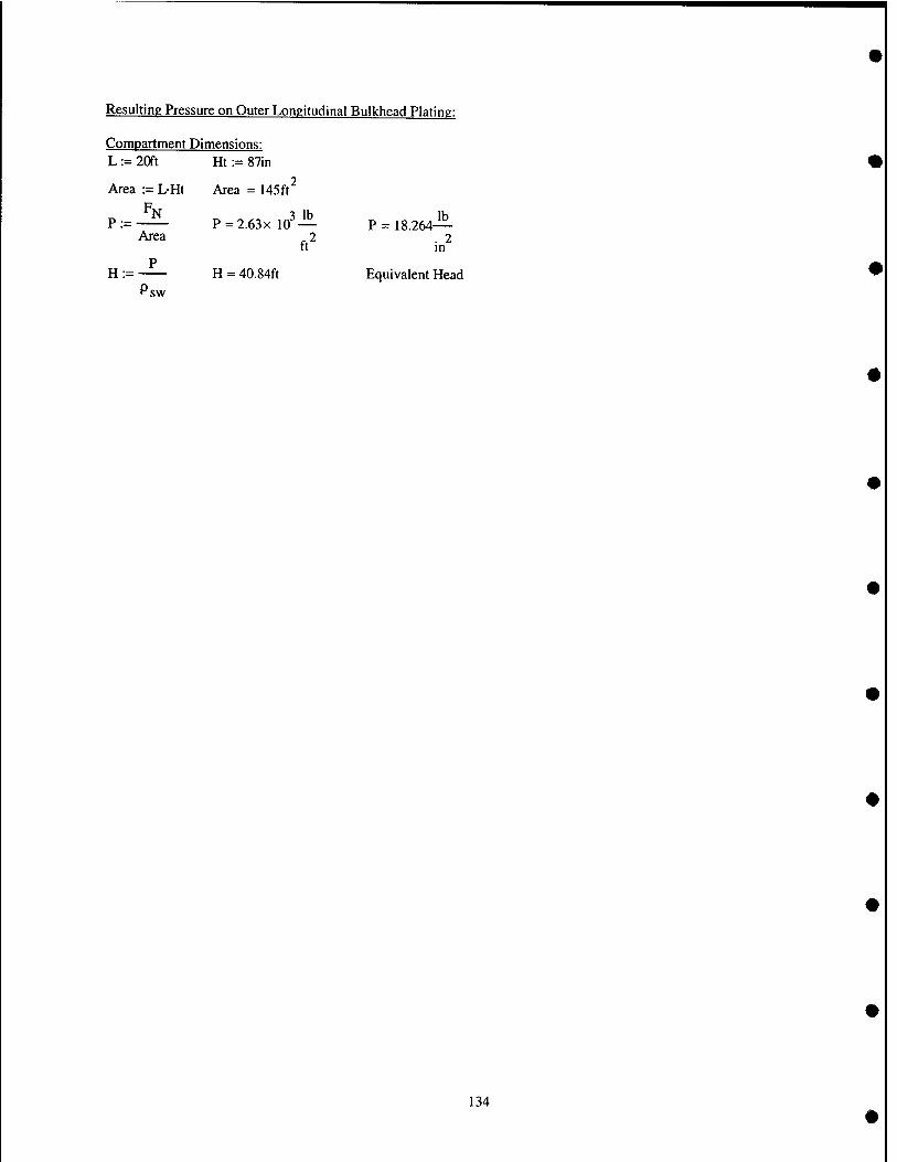
Compartment Dimensions: L := 20ft Ht := 87in
Area := L-Ht Area = 145ft^
Area P-2.63x10^'^ P= 18.264"'
. 2 m
H:= ^ Psw
H = 40.84ft Equivalent Head
134
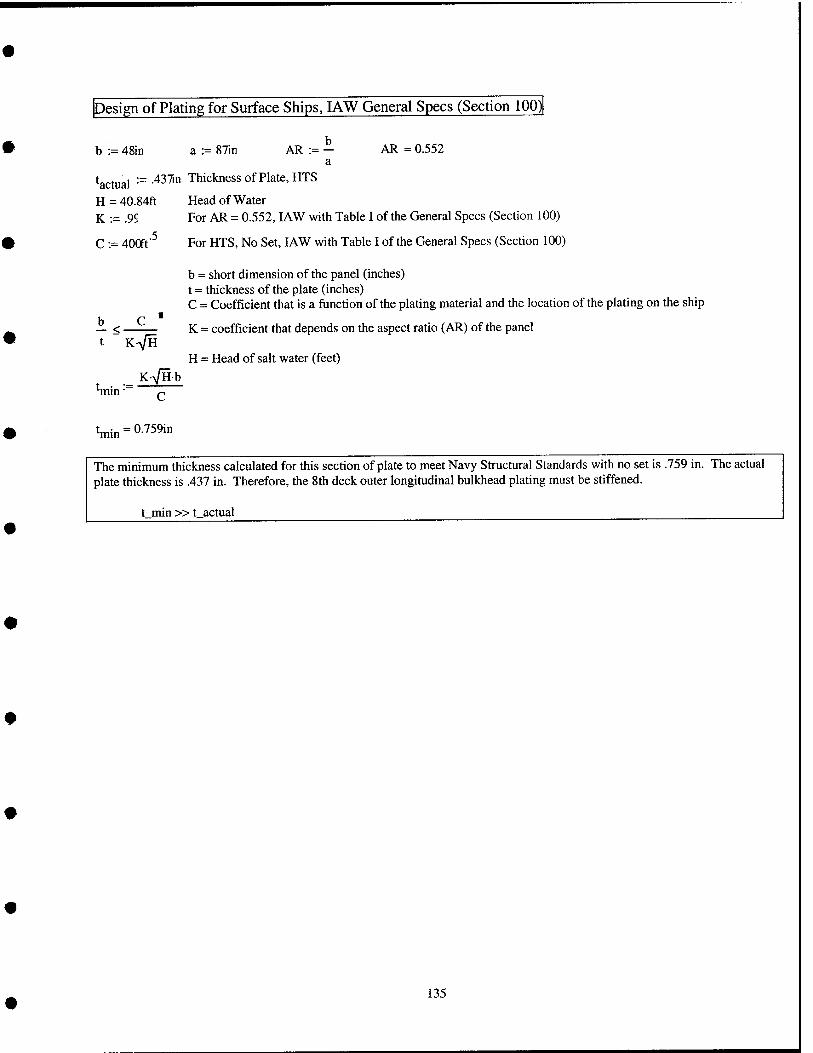
Design of Plating for Surface Ships, lAW General Specs (Section 100)|
b := 48in a := 87in AR := - AR = 0.552 a
^actual :=-43'^n Thickness of Plate, HTS
H = 40.84ft Head of Water K := .9S For AR = 0.552, lAW with Table I of the General Specs (Section 100)
C := 400ft"^ For HTS, No Set, lAW with Table I of the General Specs (Section 100)
b = short dimension of the panel (inches) t = thickness of the plate (inches) C = Coefficient that is a function of the plating material and the location of the plating on the ship
K = coefficient that depends on the aspect ratio (AR) of the panel
H = Head of salt water (feet)
^< t K-A/H
K>/Hb 'min'
Wn = 0-759in
The minimum thickness calculated for this section of plate to meet Navy Structural Standards with no set is .759 in. The actual plate thickness is .437 in. Therefore, the 8th deck outer longitudinal bulkhead plating must be stiffened.
t min »t actual
135
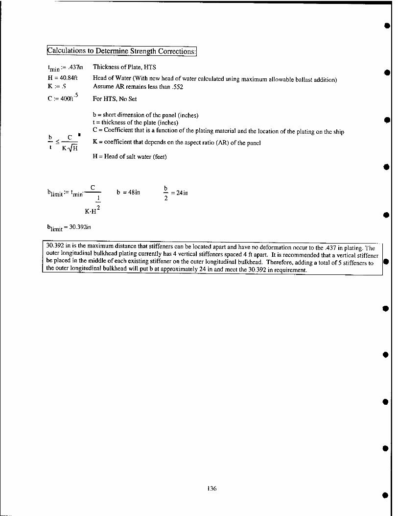
Calculations to Determine Strength Corrections:
^min '"^ -^^^n Thickness of Plate, HTS
H = 40.84ft Head of Water (With new head of water calculated using maximum allowable ballast addition) K := .9 Assume AR remains less than .552
C:= 400ft-^ For HTS, No Set
b = short dimension of the panel (inches) t = thickness of the plate (inches) C = Coefficient that is a function of the plating material and the location of the plating on the ship
K = coefficient that depends on the aspect ratio (AR) of the panel b — <
K-y/H H = Head of salt water (feet)
C h ^limit ■= ^min J" b = 48in - = 24in
2 KH
blimit=30.392in
30.392 in is the maximum distance that stiffeners can be located apart and have no deformation occur to the .437 in plating. The outer longitudinal bulkhead plating currently has 4 vertical stiffeners spaced 4 ft apart. It is recommended that a vertical stiffener be placed in the middle of each existing stiffener on the outer longitudinal bulkhead. Therefore, adding a total of 5 stiffeners to the outer longitudinal bulkhead will put b at approximately 24 in and meet the 30.392 in requirement.
136
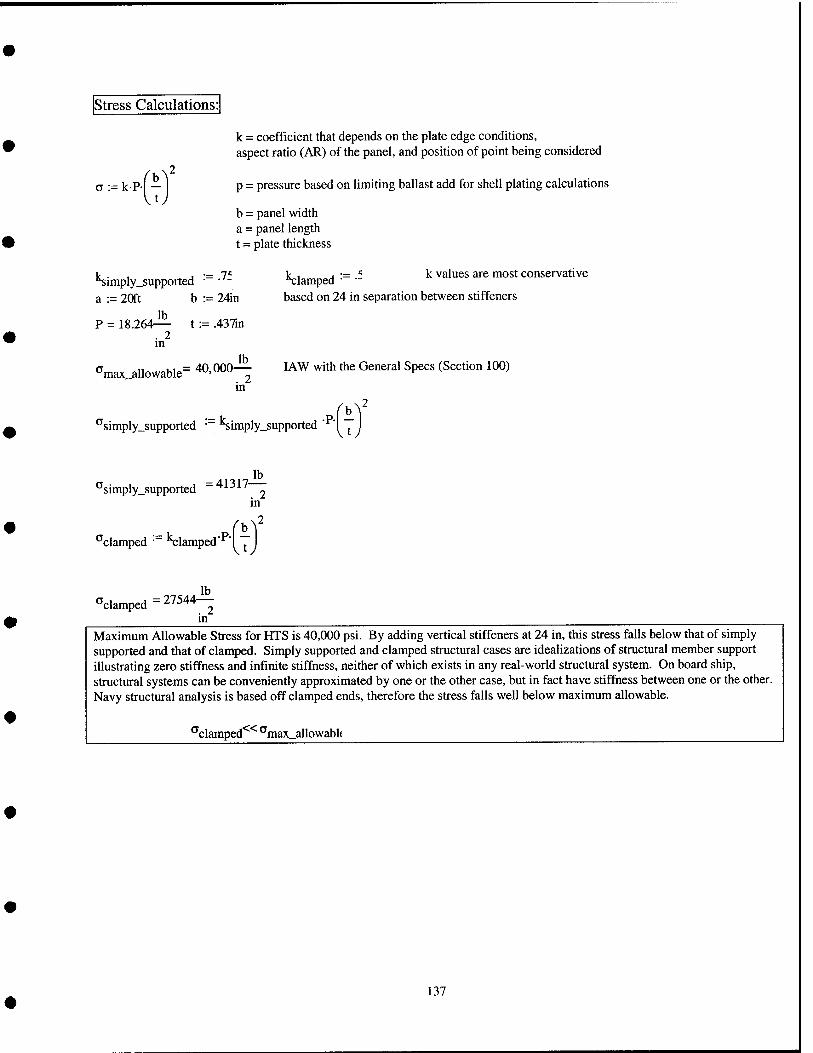
Stress Calculations
o := kP-
k = coefficient that depends on the plate edge conditions, aspect ratio (AR) of the panel, and position of point being considered
p = pressure based on limiting ballast add for shell plating calculations
b = panel width a = panel length t := plate thickness
'Simply_supported ■ a := 20ft b := 24in
IK P = 18.264— t := .437in
. 2 in
lb ^max_allowable= 40,000—
in
k , j •= 5 k values are most conservative Clamped • based on 24 in separation between stiffeners
lAW with the General Specs (Section 100)
^simply_supported • Simply_supported '^'\ ^ h^
O^; simply_supported 41317— . 2 in
^clamped • Clamped I .
clamped :27544- Ib
in
Maximum Allowable Stress for HTS is 40,000 psi. By adding vertical stiffeners at 24 in, this stress falls below that of simply supported and that of clamped. Simply supported and clamped structural cases are idealizations of structural member support illustrating zero stiffness and infinite stiffness, neither of which exists in any real-world structural system. On board ship, structural systems can be conveniently approximated by one or the other case, but in fact have stiffness between one or the other. Navy structural analysis is based off clamped ends, therefore the stress falls well below maximum allowable.
'^clamped'^^ ''max_allowabl(
137
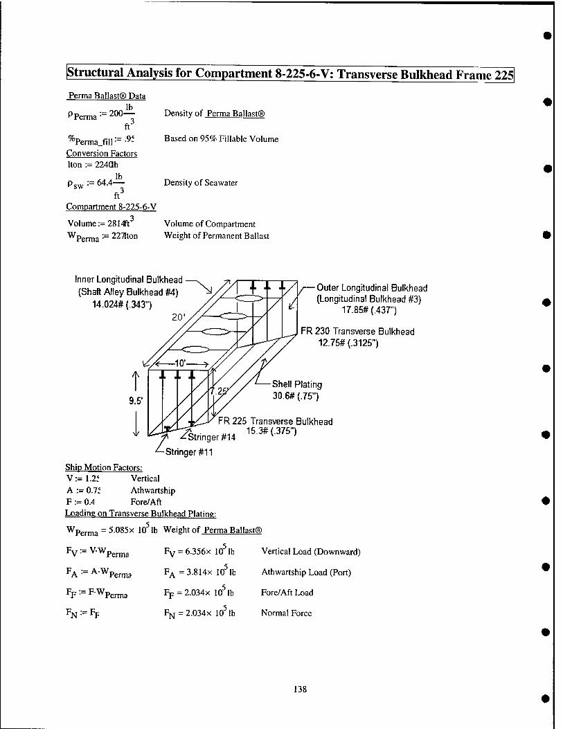
structural Analysis for Compartment 8-225-6-V; Transverse Bulkhead Frame 225
Perma Ballast® Data
Pp. erma 200J^ ft^
^"Perma.fill •= ■^- Conversion Factors Iton := 224ab
Psw ■■= 64-4-^ ft
Compartment 8-225-6-V
Volume := 2814^1^
Wperma ■= 2271ton
Density of Perma Ballast®
Based on 95% Fillable Volume
Density of Sea water
Volume of Compartment Weight of Permanent Ballast
Inner Longitudinal Bulkhead {Shaft Alley Bulkhead #4)
14.024# (.343 . 20
Outer Longitudinal Bulkhead / (Longitudinal Bulkhead #3)
'^ 17.85#(.437")
FR 230 Transverse Bulkhead 12.75# (.3125")
-Stringer #14
Shell Plating 30.6# (.75")
FR 225 Transverse Bulkhead 15.3# (.375")
^Stringer #11
Ship Motion Factors: V := 1.2f Vertical A := O.lt Athwartship F := 0.4 Fore/Aft Loading on Transverse Bulkhead Plating
Wpg^3 = 5.085x 10^ lb Weight of Perma Ballast®
Fv^=V.Wp,^3 Fv = 6.356x 10^ lb Vertical Load (Downward)
FA ■■= AWpen„3 F^=3.814x 10^ lb Athwartship Load (Port)
FF:=FWP,^3 Fp=2.034x 10^ lb Fore/Aft Load
FN := Fp FN=2.034X 10^ lb Normal Force
138
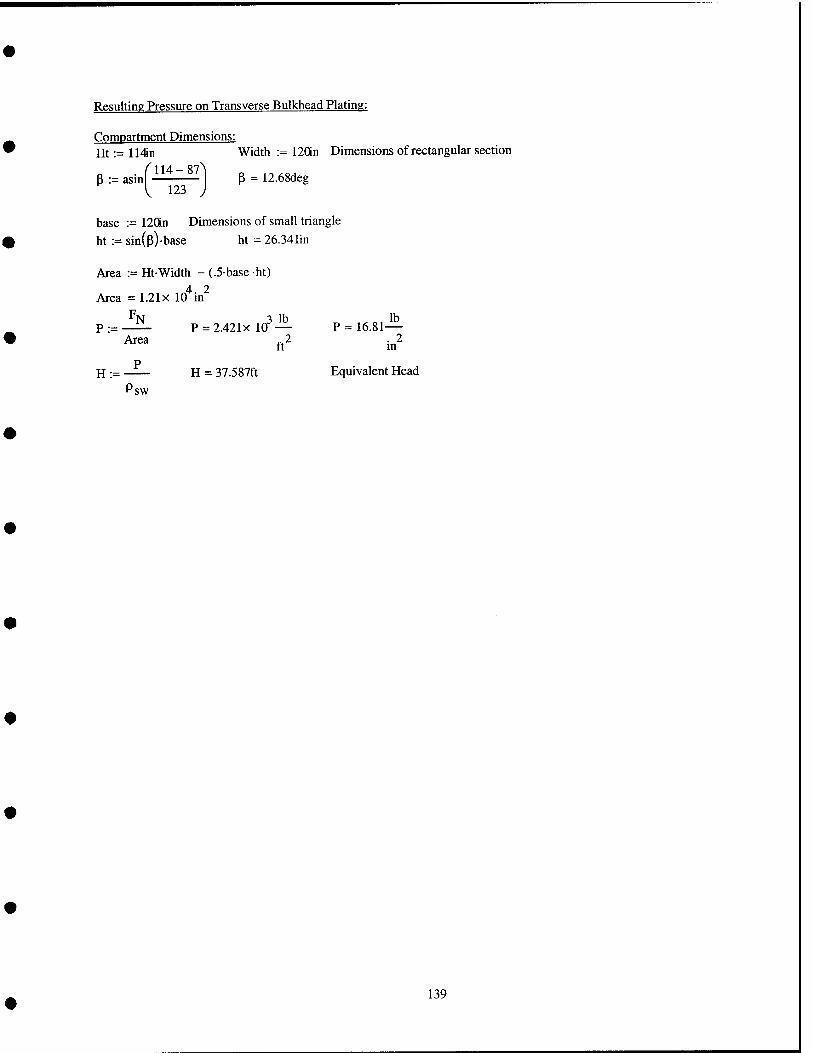
Resulting Pressure on Transverse Bulkhead Plating:
Compartment Dimensions: Ht:=lMn Width := 120in Dimensions of rectangular section
P := asinf""^"^"^! P = 12.68deg
base := 120in Dimensions of small triangle
ht := sin(p)-base ht = 26.341in
Area := Ht-Width - (.5-base -ht) 4 2
Area = 1.21x 10 in
P:=
H:= Psw
Area P = 2.421x 10''—
ft^ P := 16.81 ^^
. 2 m
P H = 37.587ft Equivalent Head
139
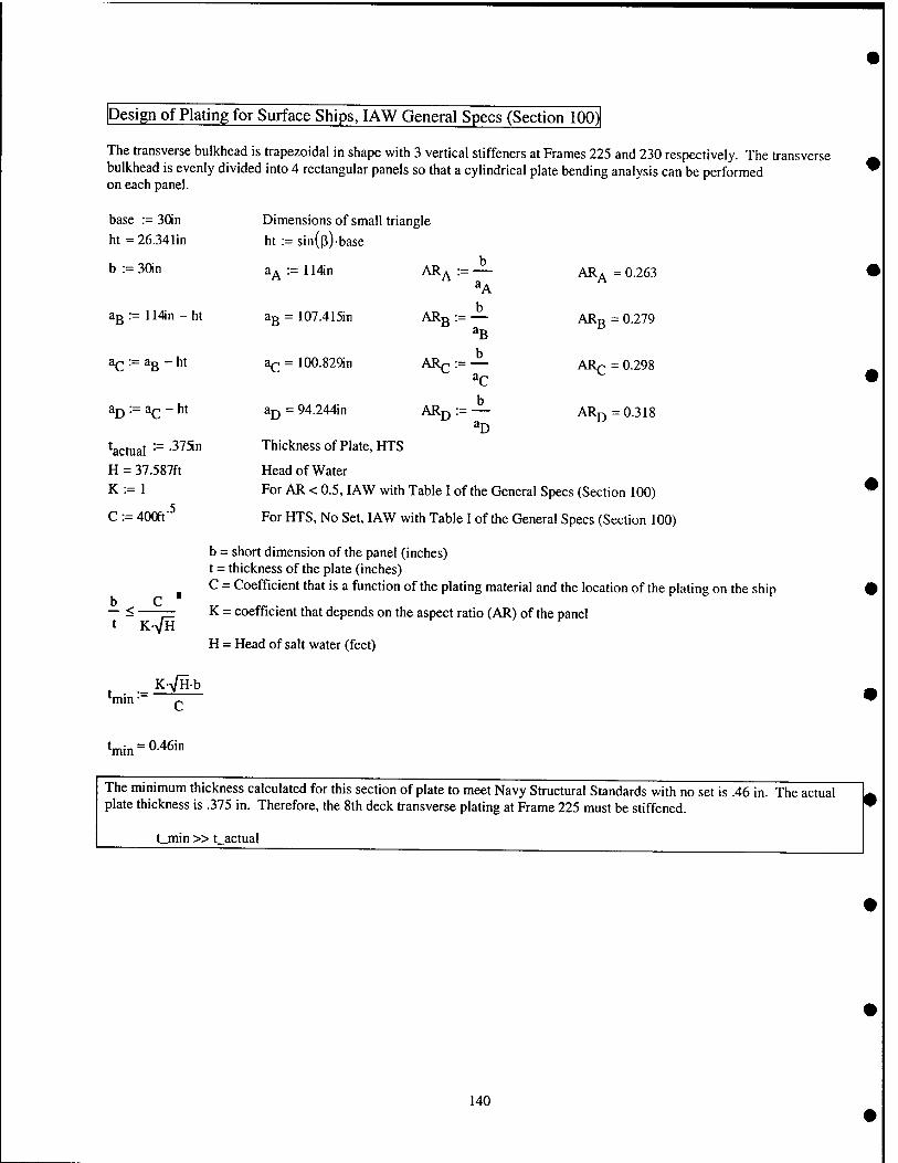
Design of Plating for Surface Ships, lAW General Specs (Section 100)
The transverse bulkhead is trapezoidal in shape with 3 vertical stiffeners at Frames 225 and 230 respectively. The transverse bulkhead is evenly divided into 4 rectangular panels so that a cylindrical plate bending analysis can be performed on each panel.
base := 30in Dimensions of small triangle
ht=26.341in ht := sin(p)-base
b := 3{)in a^ := 114in AR^ := — AR^ = 0.263 ^A
aB:=114in-ht ag = 107.415iii ARg := — ARg = 0.279
aQ-a^-ht ac = 100.82CHn ARp :=— ARp = 0.298
^D '•'= ^C ~^^ ^D = 94.244in AR^ := — AR^ =0.318 ^D
^actual -^ •^^^" Thickness of Plate, HTS
H = 37.587ft Head of Water K := 1 For AR < 0.5, lAW with Table I of the General Specs (Section 100)
C := 400ft' For HTS, No Set, I AW with Table I of the General Specs (Section 100)
b = short dimension of the panel (inches) t = thickness of the plate (inches) C = Coefficient that is a function of the plating material and the location of the plating on the ship
K = coefficient that depends on the aspect ratio (AR) of the panel b — <• t K-VH
K>/Hb
H = Head of salt water (feet)
™n-
Vin = 0.46in
The minimum thickness calculated for this section of plate to meet Navy Structural Standards with no set is .46 in. The actual plate thickness is .375 in. Therefore, the 8th deck transverse plating at Frame 225 must be stiffened.
t_min »t actual
140
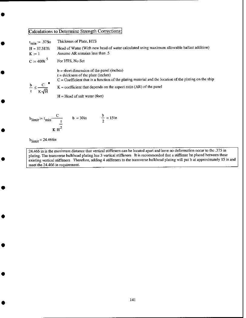
Calculations to Determine Strength Corrections:
tj^„:= .37511
H = 37.587ft K:= 1
C := 400ft'^
Thickness of Plate, HTS
Head of Water (With new head of water calculated using maximum allowable ballast addition) Assume AR remains less than .5
For HTS, No Set
b — < K-VH
b = short dimension of the panel (inches) t = thickness of the plate (inches) C = Coefficient that is a function of the plating material and the location of the plating on the ship
K = coefficient that depends on the aspect ratio (AR) of the panel
H = Head of salt water (feet)
*'limit • min
KH
b = 30in ^=15in 2
■'limit'' 24.466in
24.466 in is the maximum distance that vertical stiffeners can be located apart and have no deformation occur to the .375 in plating. The transverse bulkhead plating has 3 vertical stiffeners It is recommended that a stiffener be placed between these existing vertical stiffeners. Therefore, adding 4 stiffeners to the transverse bulkhead plating will put b at approximately 15 in and meet the 24.466 in requirement^ ^
141
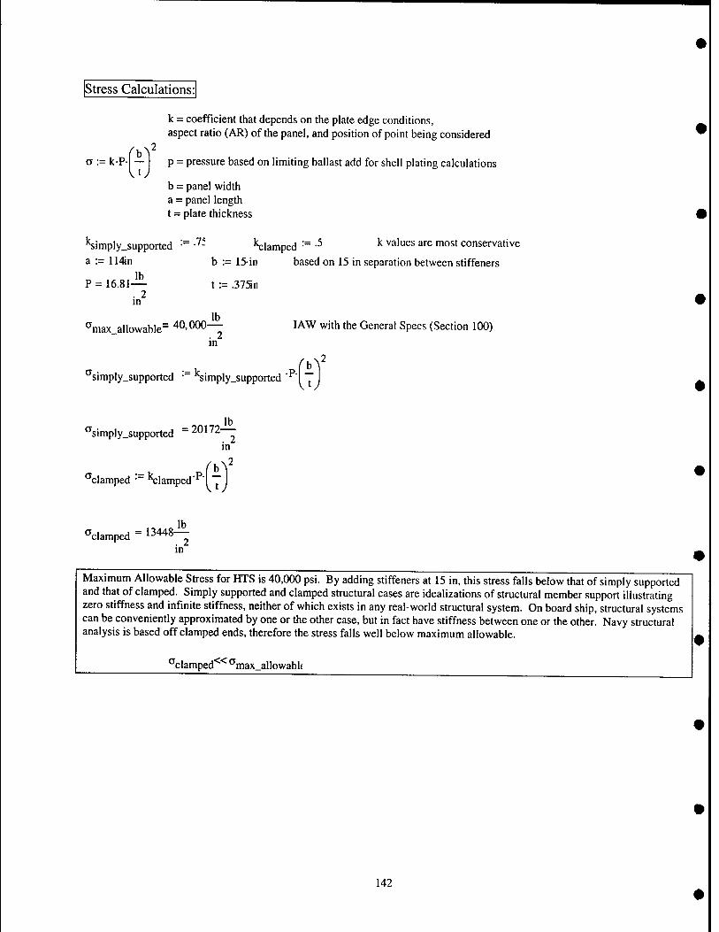
Stress Calculations:
k = coefficient that depends on the plate edge conditions, aspect ratio (AR) of the panel, and position of point being considered
o := k-P- — p = pressure based on limiting ballast add for shell plating calculations
b = panel width a = panel length t = plate thickness
•Simply.supported -^ •'^- K;lamped •= -^ ^ ^''''"^^ ^""^ "1°^' conservative a := 114Jn b := 15-in based on 15 in separation between stiffeners
P = 16.81— t := .375n . 2 m
^max allowable" 40,000— JAW with the General Specs (Section 100) . 2 m
"'simply.supported • "Simply.supported '^i
*^siniply_supported - 20172
bV
. 2 m
''clamped • "^clamped'" I I
lb "clamped = 13448—
. 2 m
Maximum Allowable Stress for HTS is 40,000 psi. By adding stiffeners at 15 in, this stress falls below that of simply supported and that of clamped. Simply supported and clamped structural cases are idealizations of structural member support illustrating zero stiffness and infinite stiffness, neither of which exists in any real-world structural system. On board ship, structural systems can be conveniently approximated by one or the other case, but in fact have stiffness between one or the other. Navy structural analysis is based off clamped ends, therefore the stress falls well below maximum allowable.
"clamped*^*^ "max_allowabl(
142
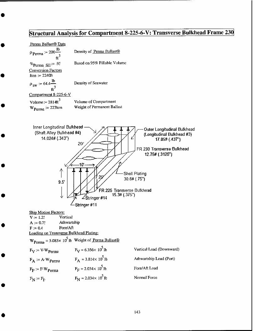
structural Analysis for Compartment 8-225-6-V: Transverse Bulkhead Frame 230
Perma Ballast® Data lb
Pp, erma := 200-
% Perma fill
ft :=.9f
Conversion Factors Iton :== 224ab
lb Psw ~ 64.4—
ft Compartment 8-225-6-V
Volume := 2814Ft^ Wperma-=2271ton
Density of Perma Ballast®
Based on 95% Fillable Volume
Density of Seawater
Volume of Compartment Weight of Permanent Ballast
Inner Longitudinal Bulkhead (Shaft Alley Bulkhead #4)
14.024# (.343' 20'
— Outer Longitudinal Bulkhead / (Longitudinal Bulkhead #3)
^ 17.85# (.437')
FR 230 Transverse Bulkhead 12.75# (.3125")
Shell Plating 30.6# (.75")
FR 225 Transverse Bulkhead 15.3#(.375l
Stnnger #14 7 '^stringer #11
Ship Motion Factors: V:=L2f Vertical A := 0.7f Athwartship F := 0.4 Fore/Aft Loading on Transverse Bulkhead Plating:
Wpgjjjjg = 5.085X 10^ lb Weight of Perma Ballast®
Fy := VWp^^g
PA •= ^•'^Perma
Fp := FWpgrma
^N'
Fv = 6.356x 10 lb
F^ =3.814x 10^ lb
Fp=2.034x 10^ lb
Fjsj = 2.034X 10 lb
Vertical Load (Downward)
Athwartship Load (Port)
Fore/Aft Load
Normal Force
143
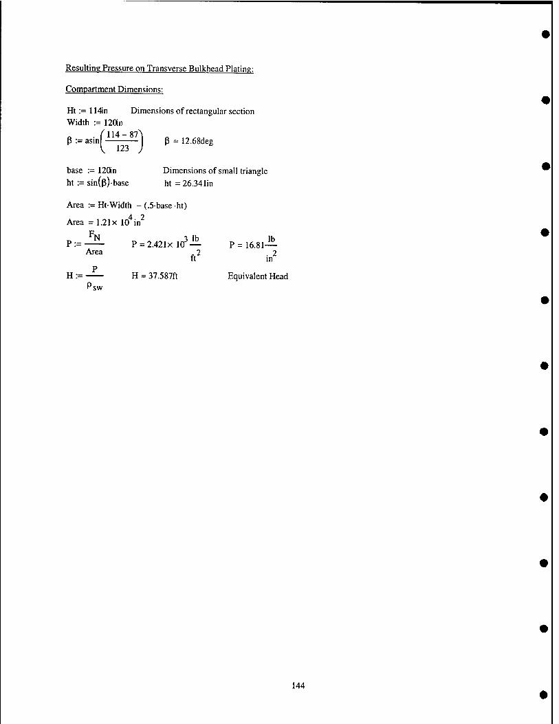
Resulting Pressure on Transverse Bulkhead Plating:
Compartment Dimensions:
Ht := 114in Dimensions of rectangular section Width := 12an
P := asm p = 12.68deg
base := 120in Dimensionsof small triangle ht := sin(p)-base ht = 26.341in
Area := Ht-Width - (.5-base ht)
Area =1.21x 10* in^
P:=— P = 2.421x10^-!^ P = 16.81— Area 2 .2
It m P
H := H = 37.587ft Equivalent Head Psw
144
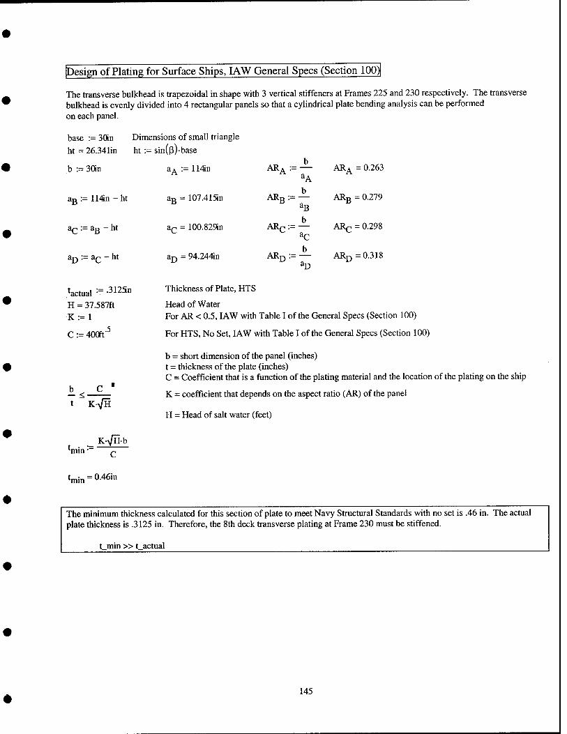
Design of Plating for Surface Ships, lAW General Specs (Section 100)
The transverse bulkhead is trapezoidal in shape with 3 vertical stiffeners at Frames 225 and 230 respectively. The transverse bulkhead is evenly divided into 4 rectangular panels so that a cylindrical plate bending analysis can be performed on each panel.
base := 30in Dimensions of small triangle
ht = 26.341in ht := sin(p)-base
b := 30in a^ :- 114in
ag = 107.415in
a^ = 100.829in
aj) = 94.244in
Thickness of Plate, HTS
Head of Water For AR < 0.5, lAW with Table I of the General Specs (Section 100)
For HTS, No Set, lAW with Table I of the General Specs (Section 100)
b = short dimension of the panel (inches) t = thickness of the plate (inches) C = Coefficient that is a function of the plating material and the location of the plating on the ship
K = coefficient that depends on the aspect ratio (AR) of the panel
H = Head of salt water (feet)
^B = 114in-ht
^ = ag - ht
^D := ac - ht
tactual := -31251 H = 37.587ft K:=l
C:= = 400ft'^
ARA b
ARA = 0.263
ARB b
^B ARB = = 0.279
ARQ b
ARc = = 0.298
ARD b
^D ARD = 0.318
t
c ■
K-VH
K^Hb TTun C
^min = 0.46in
The minimum thickness calculated for this section of plate to meet Navy Structural Standards with no set is .46 in. The actual plate thickness is .3125 in. Therefore, the 8th deck transverse plating at Frame 230 must be stiffened.
t min »t_actual
145
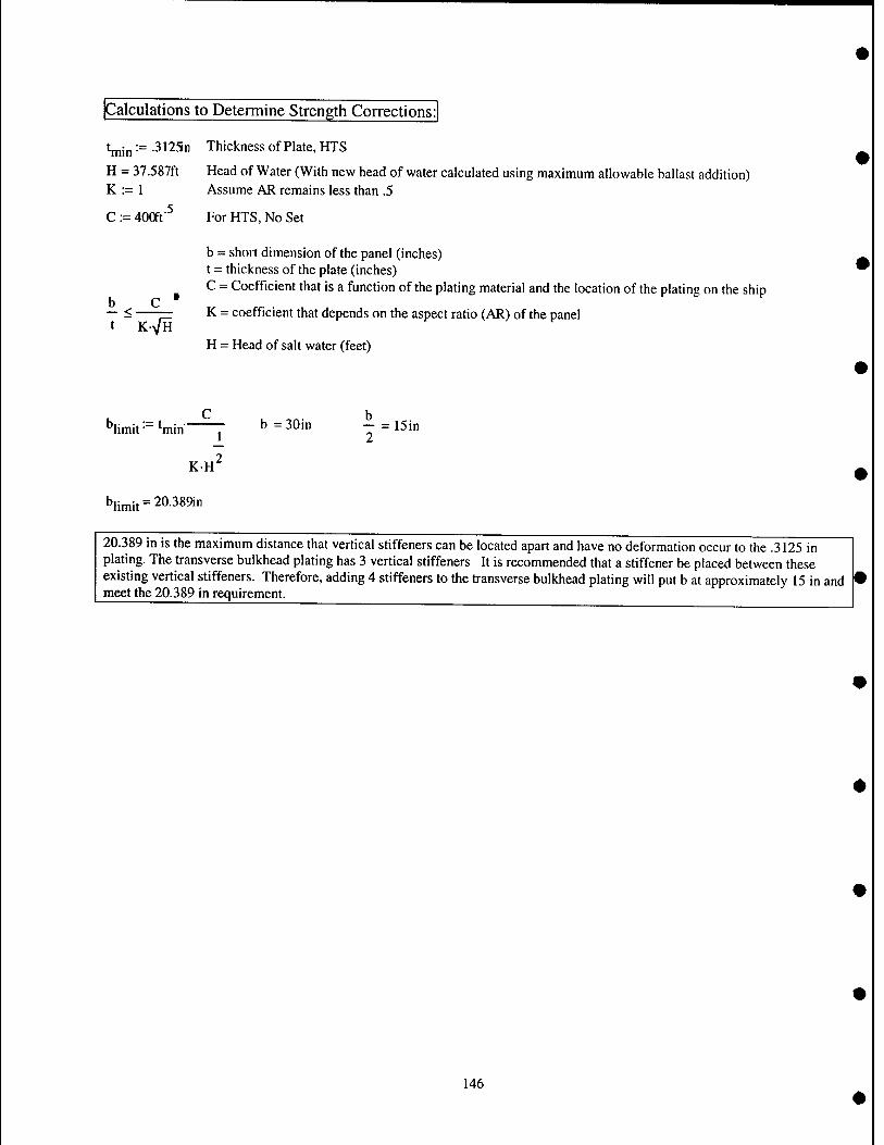
Calculations to Determine Strength Corrections:
t^jp := .3125n Thickness of Plate, HTS
H = 37.587ft Head of Water (With new head of water calculated using maximum allowable ballast addition) K :- 1 Assume AR remains less than .5
C := 400ft'^ For HTS, No Set
b = short dimension of the panel (inches) t = thickness of the plate (inches) C = Coefficient that is a function of the plating material and the location of the plating on the ship
K = coefficient that depends on the aspect ratio (AR) of the panel b c • — <•
K-VH H = Head of salt water (feet)
C h *'limit==^ %in ^ = 30i" ^ " ^^'"
2 KH
blimit=20.389in
20.389 in is the maximum distance that vertical stiffeners can be located apart and have no deformation occur to the .3125 in plating. The transverse bulkhead plating has 3 vertical stiffeners It is recommended that a stiffener be placed between these existing vertical stiffeners. Therefore, adding 4 stiffeners to the transverse bulkhead plating will put b at approximately 15 in and meet the 20.389 in requirement.
146
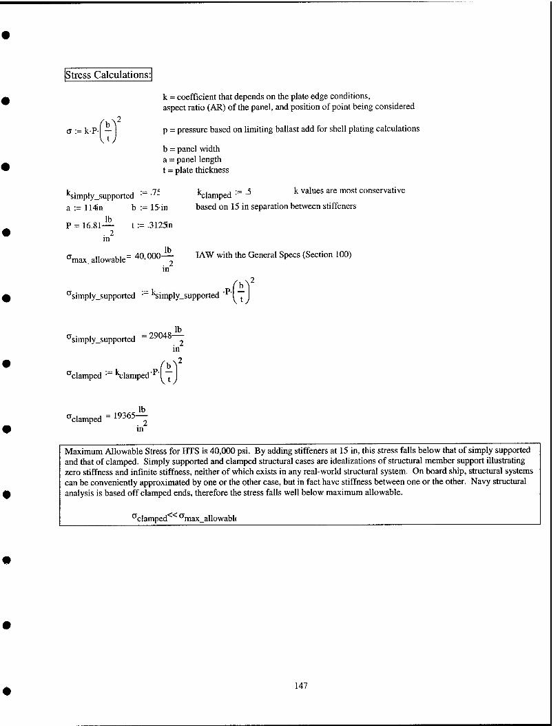
Stress Calculations:
a := kP- -
k = coefficient that depends on the plate edge conditions, aspect ratio (AR) of the panel, and position of point being considered
p = pressure based on limiting ballast add for shell plating calculations
b = panel width a = panel length t = plate thickness
'^imply_supported • a := 114in b :- 15-in
lb P ^ 16.81-
. 2 in
t := .3125n
lb "max allowable= 40,000-
m
Ic , j •= 5 k values are most conservative *t;lamped • based on 15 in separation between stiffeners
I AW with the General Specs (Section 100)
>2
^simply_supported ■ 'Simply_supported I ^
simply_supported 29048- Jb_ . 2 in
'clamped • Clamped I ^
'clamped 19365- Jb_ . 2 m
Maximum Allowable Stress for HTS is 40,000 psi. By adding stiffeners at 15 in, this stress falls below that of simply supported and that of clamped. Simply supported and clamped structural cases are idealizations of structural member support illustrating zero stiffness and infinite stiffness, neither of which exists in any real-world structural system. On board ship, structural systems can be conveniently approximated by one or the other case, but in fact have stiffness between one or the other. Navy structural analysis is based off clamped ends, therefore the stress falls well below maximum allowable.
^«a, clamped "max_allowabl<
147
Appendix F: Final POSSE Modeling Results
148
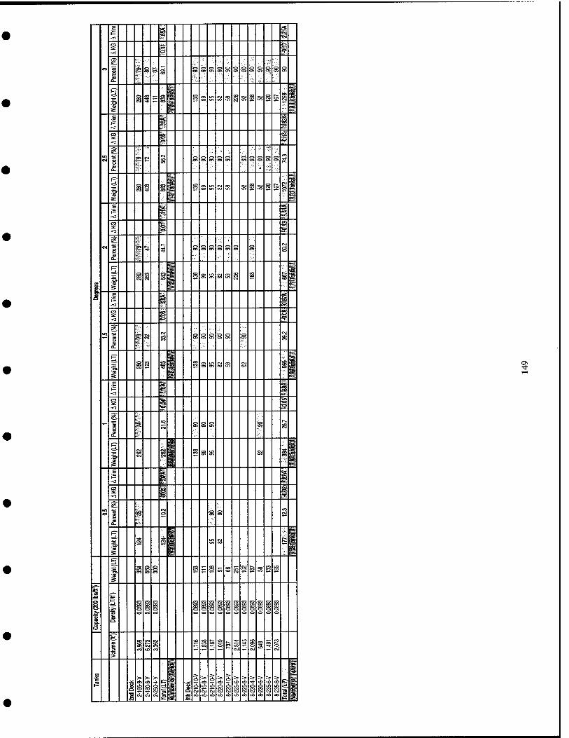
__ — __ — """ " *c; 1— ai S s <] c>
CO s r-. f->
P ai <n UJ
Q-
p & « i 00
5 ^ £3 % g in en s s CO a g s § s s S
s br 3''
e ^ rS (== tn CO
-=3 '""
-=3 i -<*• 9
?i«
(r> <-N en
1 K o> ri-
5- s
* E i i § CO s S la 35 a g a g to 1 j2 ■<u fl^ll s: u ^^^ E <■ iC:
<3 ^ B
<1 1 m
"E ,—, <~> <-> g 0 ^ o>
o> OL
m ^M F^ &to
s § 8 § g s s in sa a> S g g ^ ■m
i S fc /■''
E i g -3 W'. *"» 9 s s <1 V
^
' 1 s Si
CM
S3 g g g s ^ i S
PT .:•?, i '??
1, ^ ~ wp s s o> & en CT> i ^ » S ',.■ ^p i" E jj.
tK 1— s <1
s? g -d # "^ ftS iv
1 |: CM
8 s g S s
p- i r.M
t CM ip g s s ffl i i ^ W ^
'f= 1?
*3 1 BS
S 1 1
0 g g u P- ''' w 'f!:: H 1. a §■ 0 sa fe R S- ''- ^p Wi p- ■F s <^ R ff! ^ SR oi s m ?! a s s t«
CO
5
^ p= f^ r^ fO ro (^ ro ro ro ro fO ro
St ci fS m rT< J^ J^ ro fr< ir, ro nf< r#i nri
■i* £r 0 0 c, 0 •=> C3 0 0 c=> 0 0 0 0
ri C-1
<-> .^
CO c^ CM <%
> ,„ ..,. ^ ^ m.
1 1 i > > > c:^ 1 S S S S ci => S > r> S > c- 1 ?i -» 1 rS • h .^ rS rS nS .^ r->
a Ki C\J CM C<1 fi i# i
ob CO 00 00 00 CO CO to 00 c6 06 ■2 g
OS
Appendix G: Final Cost Estimation Data and Worksheets
Provided by Norfolk Naval Shipyard Structural Engineering and Planning Office (Code 256)
150

o o
> o
o
-o B
u <u u a a o
o u
1/3
a S
T3 a
es B (A
en N o ;a
u Si
M o
<» 'S
b2i
ON H 00 ^
^
^^
oo
^ <
\0 T—1
wo w
en a
CO ^
^ 00
^^ ■^ Tt
r-l IT) ^ 00
o
1- >H
r^ 00
r-H 1—H ON 1—1 ^ s?
WO
RK
TO
BE
AC
CO
MPL
ISH
ED
0!! O
Z >
S Vi H^ CO f<l
§ >
u <^
o CU
T/I
NST
AC
CE
SSE
S FO
R S
TIF
FEN
ING
O
o o
00
00 H
CU
T/I
NST
AC
CE
SSE
S (6
) 12
" FO
R F
ILL
ING
00 w 00 00
8 u < H 00 W H
S 00
PL, 2 o
|i
ii
TO
TA
L P
RO
D
$139
,216
M ON 2 ^5- AD
DL
WE
IGH
T:
4,47
0 #'
S
yg
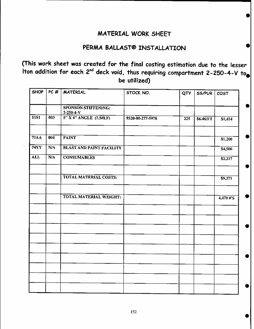
MATERIAL WORK SHEET
PERMA BALLAST® INSTALLATION •
(This work sheet was created for the final costing estimation due to the lesser Iton addition for each Z"'' deck void, thus requiring compartment 2-250-4-V tO|
be utilized)
SHOP PC# MATERIAL STOCK NO. QTY SS/PUR COST
SPONSON STIFFENING: 2-250-4-V
llSl 003 5" X 4" ANGLE (7.5#LF) 9520-00-277-5978 225 $6.46/FT $1,454
71AA 004 PAINT $1,200
74YY N/A BLAST AND PAINT FACILITY $4,500
ALL N/A CONSUMABLES $2,217
TOTAL MATERIAL COSTS: $9,371
TOTAL MATERIAL WEIGHT: 4,470 #'S
152
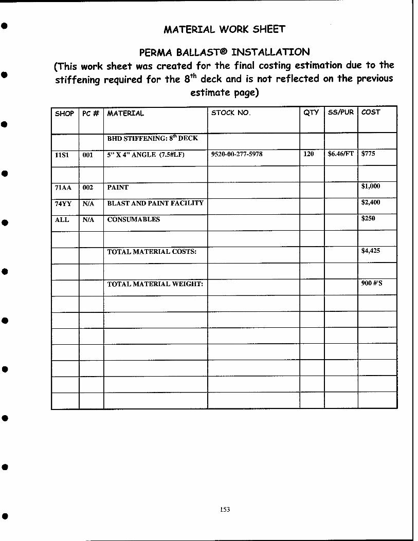
MATERIAL WORK SHEET
PERMA BALLAST® INSTALLATION (This work sheet was created for the final costing estimation due to the stiffening required for the 8^^ deck and is not reflected on the previous
estimate page)
SHOP PC# MATERIAL STOCK NO. QTY SS/PUR COST
BHD STIFFENING: 8"" DECK
llSl 001 5" X 4" ANGLE (7.5#LF) 9520-00-277-5978 120 $6.46/FT $775
71AA 002 PAINT $1,000
74YY N/A BLAST AND PAINT FACILITY $2,400
ALL N/A CONSUMABLES $250
TOTAL MATERIAL COSTS: $4,425
TOTAL MATERIAL WEIGHT: 900 #'S
153
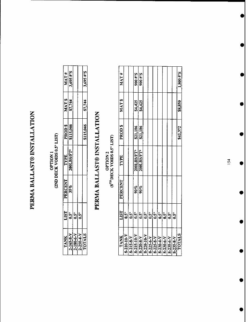
o >
u Ed O
N
*
so
«5
5
1 o
i
i as o o
0 o
d
z >
I 00 i
I
>
o M
I 1
r» d
oa
u Q
00
1/1 *
ON 00
VJ «ft © Ift 00 00
Q O CL,
00 I-l
El oa o
oa o o
H Z a u
1 © ©
H 0 d
o in d
o
d o Ift
d o Ift
d 0 o
Ift
d o Ift
d 0 Ift
d o Ift
d 0 Ift
d
z ■ o •
00 ■
00
> o i-i
•ft 1^
1 00
> 1
00
00
> 6 rH
1 00
> ■
Ift r^
■ 00
> Ift
1 00
> ■
00
> ■
2
> I
SO 1
00
> • 00 •
• 00 i
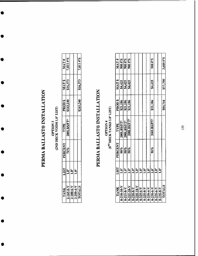
H
o o
^ u Ed
fs
*• en M * 5fc
S 00 00
^■ p H CO f^ < SD ^o § rH TH ««- </*
^ ? 0
U «S <s 0 f^' Q
£ ^ ^» <^
Cd I4
eu 1/J
r:
H Z
0« ? M BU
H 0 0 0 {/) 0 0 0
J 1H T-l 1—1
> > > c«
Z 4 4 00
©
I-I < H 0 H fH rH n
r^ M f<i H
CO
Z o H O
CO
Z < H
U
* yj c« 1/3 CO CO 5^
H * 3fc * * -<*! 0 ^ 0 0
S 0 (^ 0 •© vn OS c W\
f<^
<«■ VJ Wl tT) Vi © ©
H ^ ?? ^ s^ ■6^
rH
^■ se vo \a SO 3: Q 00 00 00 00 Tf
rH rH y-t rH t^ 0 i-H rH y-< rH ■*
Pi r<« «S r» «S 00 PH ^ <«■ <^ <«• *«•
m m m ^ H H
§ ^ M W5 pa pa
1-} s 0 rJ ©
e © 0 0 0 »s n <s PI
^ Z
^ ^ ^ ^ 0 0 © © ets «\ » a\ »\
M PH
H 0 0 0 0 n 0 n 0 n 0 0
c« 0 0 © © © © © © © 0 ©
h-] i-H rH rH ^ rH rH T^ rH rH 1-H wi
1 > > ©
rH > % > > > > > >
CO rJ
00 00 ^^ \o *? T "^ ^ 00
6 <r) in © © Vi Vt © © V) «n 1-H rH rH fs »s «s «s fo fO fo fO f^ <V n fs m r< r« n (M r« r^ 00 00 00 00 00 00 00 00 00 00 00
10 10

So
U U
00 in *
00
00 00 m
00 00
Q O
ID o
1 00
>-
i ©
s ^
o o in
o v\ f-H
> I
00
I-t
> • o
00
> I
o ■
2
i
t/3
o CO
u u Q
00
4t
H <<
CO
5fc o o OS
CO 5fc
CO
o
CO * o o 0\
CO
0\
CO
in
«n in © in m
00
1-? 1^
00 00 1-1 l-H
1-H 1-H
00 rH I-H"
T-i t-H
>< H s
oa
i n to SQ o o
PQ
i PQ
i Z
1 O 9\ o 0\ O
^ g ^ g o
fe NN NJ
0
1-5
o in 1-5
o in 1-5
o in 1-5
o in 1-H
o in rH
o in 1-5
o in 1-5
o in
o in 1-5
o «n 1-H
z >
o
>
1 00
> ■ o
1-H
m *? 00
> • 00
i 00
> 1-H
00
> I
SO
2
> of)
!Q ■
00
> 1
o ^ 00
>
00
>
i 00
> ■
00 I
1 00
CO
S
in
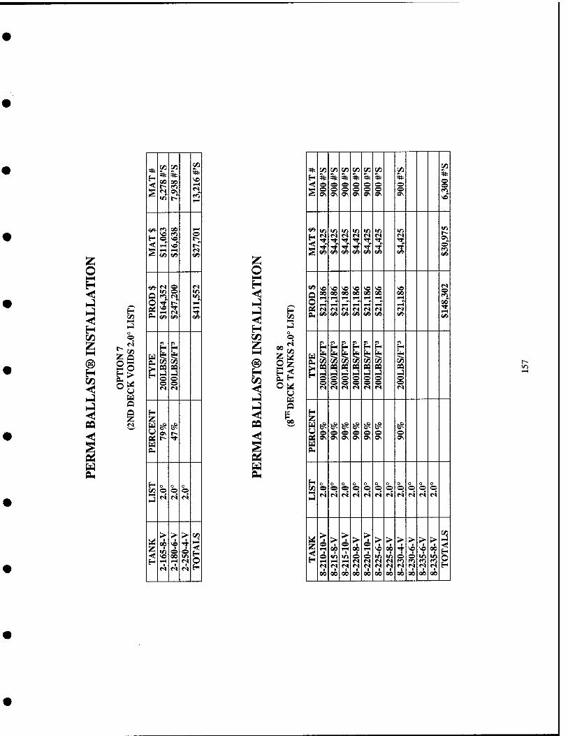
o
H OH o o
Q
H
Q O PM
H Z U
Z
CO 5t CO 00
00
VO
o o
pa o o
o
■se-
H
00
Z o H O
o
H O H
en St
0\
CO 5t o ©
St o o o
3t c« W3
St:
ON
CO
* o ©
NO
H >/5
©
Q O
VO 00 00
rH rH~
00 rH^ rH^
rH rH 1-H rH
NO 00 rH rn" »S
s 00 •<!r rH
g ^
pa
i 1 o 1 O o s O rJ
1 u o ON o 0\
^ ^ ^ ^
^ g ^ g O
0\
H
3 o O r4
o o 0 O 0 O o o o O o o o o f4
o O
o o r4
o o r4
Z >
o r-l
o&
00
rH
00
> 6 rH
>A rH
00
>■
00
00
> 6
00
> I
00
> I
00
> f
o
00
NO
o
GO
> NO
■
00
> I
00
00
CO
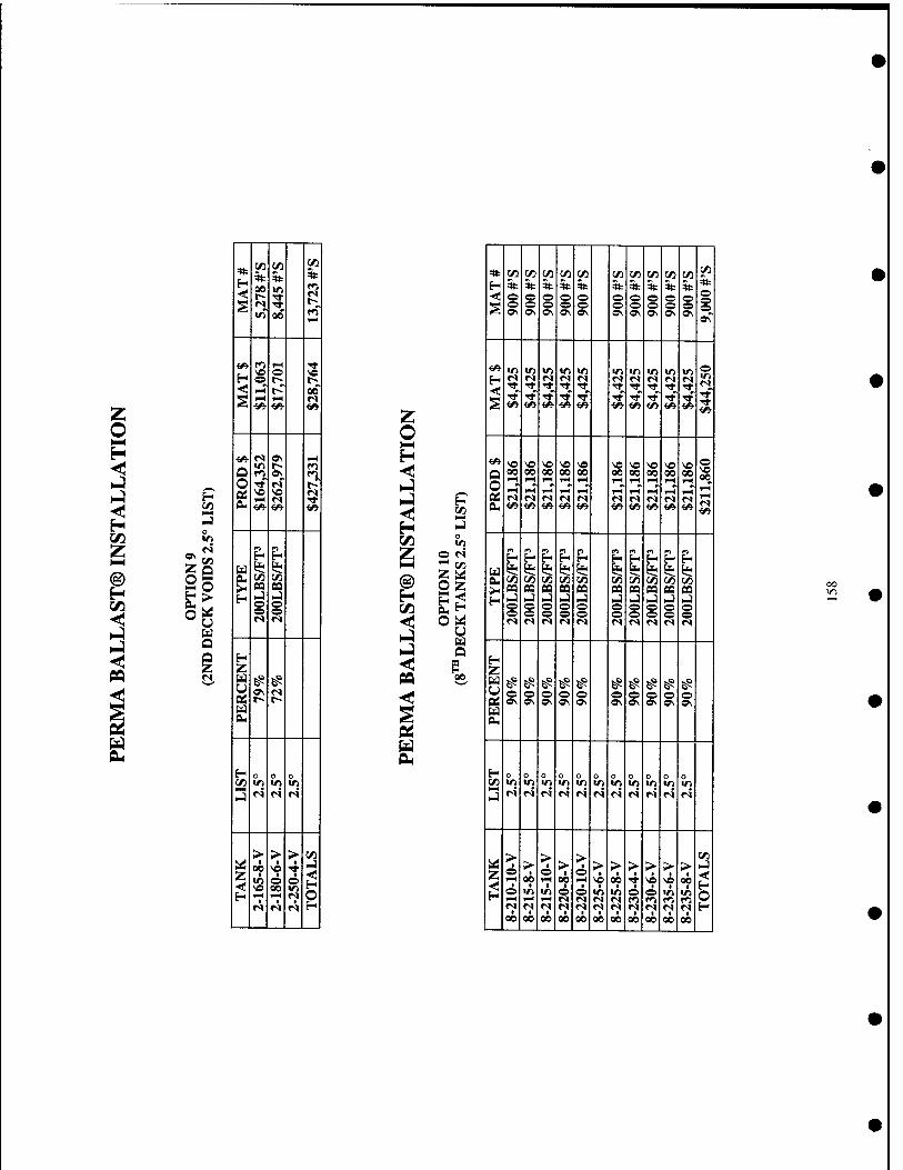
a\ V)
* H <:
5t in
3t 00 i? R
S 00 1^
•w i*i l-H Tt
H ^ ^ VO
< i^ r~- 00
S 1^ I-H n «» f«^ <A
f^ «s OS I-H
§ lO r- rn n 9\ n ■^r fS r-
« OM
vo VC «s w^ *N Tt Vi f^ ^■
ri n
u ^ fe? a. W3 ^
^ CQ CO U NJ o O o O r^ r»
H Z
£? E^ 9\ «s u t~- r--
a Pu
H o o o C/l m Vt »/) NJ
fS «s n
> > > C/l
tli^ ■ 00 VO
■ >-]
z, <
■ o 00
O 1 H 1-H TH r« p!« <S n H
C/3
c«
Z <: H
U a a 00
«: (Zl C/3 C/5 C/1 C/) V) C/l C/1 C/1 in on E- * * * * * * * * * •«
* * < o © © © ^ © ^ ^ © © ^ S o © © © © © o o © ©
0\ 0\ Oi o\ »\ 0\ »v Ov 0\ *r
^ *n v> in «r) V) m 1/1 lO •n m © n Si! «s n «s «N »s «s «N rq <s
^' i^ ^ <^ <^ v> ^ «^ i/i ^ «» ^
i«- \« VO VO VO VO VO VO VO VO VO ©
Q O C6
00 00 00 00 00 00 00 00 00 on ^ rH 1—( »-H l-H 1H lH rH TH
FH 1-H f-H 1-H rH rH f-H 1-H 1-H <S ri «s «N «s «N «S rq IS fs &. <«^ {«• f« <» Vi ^ ^ ^ <«■ i/» ^
(0 n n w fn n t^ ^ H l«H H H U l* ^ 1*1 I* l? ^ ^ SJ^ ^ eu !/D ^ ^ ^ (A t/l ^ ^ r/1 C/l
>' n BQ sa oa ca CQ 09 CQ oa 09 H u .4 u NJ NJ >-) HJ .J NJ .J o o © © o © © <^ O) © © 1^ ^5 © © f^ © <s n n «s n n <s fs <s r»
H Z
^ ^ ^ ^ ^ ^ ^ ^ ^ ^ o © © © © © o © © ©
Q£ OS ©\ OS *\ »N Ov »\ ON 0\ ©\ U eu
H o o o o O o o o o o o irt *r> trt W1 V) tn V) VI «n >o ID >n NJ
n «N <S r^ r« fS n n (S <S «s
> ■ o 1
> © >
1
> 6 > > <► > > > 2
i l-H 00 1^ 00 1-H "? 00 TT VO VO *? o «o tn © © m m © © in in 1-^ 1-H 1-H (S <N «s «N r^ m r^ ro «s <s «s <M «S n r» M ri <S r< H 00 00 00 00 00 00 00 00 00 00 00
00 in

in
o
O u o Z
* CO
*
vT
*
00
in
r4~
*
vT
1 I-H
i ON
Si 2
1
BL(
H 0
1 0
0 0
H Z
P5
0 ©
0 0
0 0
> ■
• >
■ so 6 00 1-1
1
> -4 0
■
2
i
1/3
ZQ 2o
O
* cr C/l [/) C/l C/1 t/i t/i 1/5 t/l C/3 cr c«
H * * * * * * * * * * * © <i1 © © © ^ ^ ^ © © ^ © ©
§ © © © 0 0 0 © © 0 © © fTN »\ o\ a\ o\ ON o\ ON ON ON ON
^■ *n m iri v> V) in VI v> V) V) V5 VI 5S r» «s <N n <s <N «s n r^ C! D! TT Tt ■^r rr TT TT Tt Tl- Tl- ■* Tf
Tt rr TT TT Tl- ■* rr ■* ■<t TT ■*
^■ <» i«- *» <» «9- «» ^ *«■ <» <^
■^ VO V© V© SO vo \o s© NO SO NO SO so
Q 00 00 00 00 00 00 00 00 00 00 00
0 f^ 0j r^ <s (N fs rq n r< <s rq «S <s eu ^^ -e^ «* i«- ^«- ■^ {^ <^ <«■ <^ ^^
fl ^ ^ H H H ^
u 1? ^ ±1 ^ 1? i*< 1*1 is
I C/l (/i V) ^ ^ C/1 t^ ^ m C/1 C/3 n oa pa PQ pa oa M pa pa pa pa i-j hj hj ^ NJ K-) hJ hj I-; I-) I-; © © © © © © ^^ ^s © © © 0 ^ © © © © 0 0 © <s fS n <s »s n fS r« r< <M ri
H Z
0 ^ ^ ^ ^ ^ ^ ^ ^ ^ ^ ^ © © © © © © © © © © ©
tc Ov o\ ON o\ o\ 0\ ON Os ON ON ON
U CLl
H 0 0 0 0
C/l 0 © © © © © © © © © ©
J f«% fc ro f5 f^ f^ f^ rr, fO f^ r<^
Z H
5 > 1
00 © 1—1 00
6 I-H
> 4
> ■
> SO
> I
NO > 00
6 «n v> © © VI V) © ^ VI v> rH fH 1—1 «s r< «s fS r<^ fTJ fO r*^ n ^ n «s »s r« <s n fM r< ts 00 00 00 00 00 00 00 00 00 00 00
ON