A simulation study on the effects of particle size on the consolidation of polymer powder...
13
A simulation study on the effects of particle size on the consolidation of polymer powder impregnated tapes S. Padaki, L.T. Drzal * Composite Materials and Structures Center, Department of Chemical Engineering, Michigan State University, East Lansing, MI 48824-1326, USA Accepted 17 June 1998 Abstract The powder prepreg technique offers a low-cost, high-speed method of manufacture of composites. Consolidation of the prepreg tows is a key step in the manufacture of a final ‘useful’ part. The efficiency of the consolidation for any polymer powder prepreg tape produced from a powder prepreg process would conceivably depend on the material properties of the polymer, particle size, temperature, consolidation pressure, and volume fraction of the tape. A mathematical process model that identifies and describes a set of parameters to predict the consolidation conditions of a given polymer powder prepreg tape has been developed. A simulation study that identifies the different parameters and compares the advantages and limitations of polymer physical properties and particle size has been performed. An integrated Flow Resistance (FR) Index has been developed to mathematically describe the consolidation process. The results show that small powder particle sizes are beneficial to the process. q 1999 Published by Elsevier Science Ltd. All rights reserved. Keywords: A. Tape; A. Prepreg; Particle size 1. Introduction Composite materials have gained acceptance as replace- ments for traditional structural materials in many of today’s industries. Their excellent strength to weight ratio benefits are being widely utilized, producing more fuel efficient ground transportation systems, superior recreational goods and higher performance aerospace vehicles. Polymer matrix composites have an aerospace history which emphasized high structural performance with cost being a secondary consideration. Durable goods (transportation, appliance, construction, etc.), infrastructure (bridges, decking, etc.) and off-shore oil platform applications, promise to increase the use of polymer composite materials by several times if lower cost and environmentally safe processing methods can be found to manufacture these materials. Conventional proces- sing methods rely on long process cycles and/or use of toxic solvents. These aid the processability but result in higher monetary and environmental costs. Polymers used as matrices in composites can be broadly classified into two categories—thermosets and thermoplas- tics. Of the two, thermosets have traditionally dominated the polymer composite industry. In recent years, there has been an increasing interest in the use of thermoplastic matrices for composite applications. High strain-to-failure, increased fracture toughness, better impact tolerance, shorter molding cycles, infinite prepreg shelf life, recyclability and repar- ability are some of the potential reasons for the growing interest in their development. However, applications of ther- moplastic matrix composites have been limited due to the difficulty in fabrication arising essentially from their high melt viscosities. Many approaches have been developed for the processing of thermoplastic composites. These include the following. • Solution processing —dissolving the resin in a suitable solvent and impregnating the tow with dilute solution which is later processed to remove solvent [1]. • Melt impregnation —forcing molten polymer into a fiber tow to form a prepreg tape [2]. • Film stacking —compacting alternate layers of fiber with thin sheets of resin [3]. • Filament bundle coating —sheathing small filament bundles with the thermoplastic polymer [4]. • Co-mingling —weaving together reinforcing fibers with thermoplastic matrix fibers to get a shapeable fabric [5]. • Slurry processing —drawing the fiber tow through a suspension of solid, small polymer particles suspended in a liquid carrier [6]. Composites: Part A 30 (1999) 325–337 1359-835X/99/$ - see front matter q 1999 Published by Elsevier Science Ltd. All rights reserved. PII: S1359-835X(98)00115-8 * Corresponding author.
Transcript of A simulation study on the effects of particle size on the consolidation of polymer powder...

A simulation study on the effects of particle size on the consolidation ofpolymer powder impregnated tapes
S. Padaki, L.T. Drzal*
Composite Materials and Structures Center, Department of Chemical Engineering, Michigan State University, East Lansing, MI 48824-1326, USA
Accepted 17 June 1998
Abstract
The powder prepreg technique offers a low-cost, high-speed method of manufacture of composites. Consolidation of the prepreg tows is akey step in the manufacture of a final ‘useful’ part. The efficiency of the consolidation for any polymer powder prepreg tape produced from apowder prepreg process would conceivably depend on the material properties of the polymer, particle size, temperature, consolidationpressure, and volume fraction of the tape. A mathematical process model that identifies and describes a set of parameters to predict theconsolidation conditions of a given polymer powder prepreg tape has been developed. A simulation study that identifies the differentparameters and compares the advantages and limitations of polymer physical properties and particle size has been performed. An integratedFlow Resistance (FR) Index has been developed to mathematically describe the consolidation process. The results show that small powderparticle sizes are beneficial to the process.q 1999 Published by Elsevier Science Ltd. All rights reserved.
Keywords:A. Tape; A. Prepreg; Particle size
1. Introduction
Composite materials have gained acceptance as replace-ments for traditional structural materials in many of today’sindustries. Their excellent strength to weight ratio benefitsare being widely utilized, producing more fuel efficientground transportation systems, superior recreational goodsand higher performance aerospace vehicles. Polymer matrixcomposites have an aerospace history which emphasizedhigh structural performance with cost being a secondaryconsideration.
Durable goods (transportation, appliance, construction,etc.), infrastructure (bridges, decking, etc.) and off-shoreoil platform applications, promise to increase the use ofpolymer composite materials by several times if lowercost and environmentally safe processing methods can befound to manufacture these materials. Conventional proces-sing methods rely on long process cycles and/or use of toxicsolvents. These aid the processability but result in highermonetary and environmental costs.
Polymers used as matrices in composites can be broadlyclassified into two categories—thermosets and thermoplas-tics. Of the two, thermosets have traditionally dominated thepolymer composite industry. In recent years, there has been
an increasing interest in the use of thermoplastic matricesfor composite applications. High strain-to-failure, increasedfracture toughness, better impact tolerance, shorter moldingcycles, infinite prepreg shelf life, recyclability and repar-ability are some of the potential reasons for the growinginterest in their development. However, applications of ther-moplastic matrix composites have been limited due to thedifficulty in fabrication arising essentially from their highmelt viscosities.
Many approaches have been developed for the processingof thermoplastic composites. These include the following.
• Solution processing—dissolving the resin in a suitablesolvent and impregnating the tow with dilute solutionwhich is later processed to remove solvent [1].
• Melt impregnation—forcing molten polymer into a fibertow to form a prepreg tape [2].
• Film stacking—compacting alternate layers of fiber withthin sheets of resin [3].
• Filament bundle coating—sheathing small filamentbundles with the thermoplastic polymer [4].
• Co-mingling—weaving together reinforcing fibers withthermoplastic matrix fibers to get a shapeable fabric [5].
• Slurry processing—drawing the fiber tow through asuspension of solid, small polymer particles suspendedin a liquid carrier [6].
Composites: Part A 30 (1999) 325–337
1359-835X/99/$ - see front matterq 1999 Published by Elsevier Science Ltd. All rights reserved.PII: S1359-835X(98)00115-8
* Corresponding author.

• Dry powder prepregging—impregnating the fiber towwith a dry powder form of the polymer [7].
• In-situ polymerization—preimpregnating the fiber towwith a low molecular weight prepolymer and subse-quently polymerizing a linear chain in situ [5].
Fig. 1 is a schematic representation of the differences inthe various methods available for prepreg manufacture.Prepreg is a precursor to the final composite and consistsof the reinforcing fibers and the polymer matrix in an uncon-solidated form. Consolidation is the process step thatconverts a composite prepreg into a fully densified, comple-tely void-free part. The ‘ideal’ final consolidated prepregwould resemble Fig. 1(a) where each fiber is equallyspace and is wetted completely by the matrix. Solvent orslurry processing techniques (Fig. 1(b)) need the extra stepof solvent/carrier fluid removal prior to consolidation. In themelt impregnation process (Fig. 1(c)), a high viscosity poly-mer needs to impregnate the small interstices presentbetween fibers which sometimes results in voids. Prepregsthat are made to minimize long range flows (e.g. fibercommingling and powder impregnation) seem, therefore,to be an ideal alternative. However, the increased cost asso-ciated with commingling (Fig. 1(d)) of polymer and reinfor-cing fibers leaves only the dry powder processes as viablealternatives for the manufacture of thermoplastic prepregtape [8]. Because of the high viscosity of polymer matrices,
low temperature methods using organic solvents haveusually been used to manufacture these material forms.This keeps the manufacturing costs high due to the extrastep needed to remove the solvent. Even low levels of voids( , 1%) of retained solvent seriously reduce the mechanicalproperties of the resulting composite material. In addition,the solvents used could be toxic and pose an environmentalrisk resulting in expensive safety solutions. New processingmethods employing dry polymer powders offer the solutionto this problem.
2. Powder impregnation technology
Impregnation of fiber tows with polymer powder and thesubsequent firm attachment of these particles on the reinfor-cing filaments to produce aprepreg is the key step in thesolvent-free manufacture of composite materials. A prepregis a precursor of the final composite structure and consists ofthe reinforcing fibers and polymer matrix in a partly conso-lidated form. Various modes of dispersing the polymerpowder and impregnating a spread fiber tow have beendeveloped by several research groups. These processesdiffer mainly in the way the particles are deposited on thefibers and the particle–fiber forces responsible for theiradhesion to each other.
In the majority of the dry processes the spread fibers arepassed through an air suspension of particles. Fiber towspreading, particulate flow pattern, particle size, dielectricproperties of fibers and particles, and the particle cloudconcentration are some of the main factors that influencethe mode and rate of powder deposition.
Powder fluidization (or aerosolization) is a balancebetween fluid dynamic forces, gravitational and inter-parti-cle forces. The dominant force of interaction between theparticles in a powder is the van der Waals force of attractionprovided the separation distance between particles is lessthan 1mm [9]. Surface asperities or roughness of the parti-cles can nullify this force if the effective separation distancebetween particles increases to more than 1mm. Other attrac-tive forces that can be involved are capillary forces (in thepresence of moisture) and electrostatic forces.
An overview of the different processes is presentedbelow. Table 1 lists the advantages and disadvantages asso-ciated with each process.
S. Padaki, L.T. Drzal / Composites: Part A 30 (1999) 325–337326
Fig. 1. Differences in the processing of composite prepregs.
Table 1Relative advantages and disadvantages of composite powder processing technologies
Method Costs Size of powder (mm) Energy Vf control Control over distribution Additional processing steps
Conventional fluidized bed Low 50–200 Low Poor Poor NoneElectrostatic fluidized bed High 50–200 Medium Good Good NoneAcoustically fluidized bed Medium , 50 Medium Good Good NoneRecirculating fluidized bed Medium 50–200 High Poor Poor NoneMoisture assisted deposition Medium 50–200 High Good Poor DryingLiquid phase deposition Low , 10 High Good Good DryingElectrostatic spray Medium 1–250 Medium Medium Good None

2.1. Conventional fluidized bed technology
Price [7] was the first in padding a glass roving through abed of either fluidized or loosely packed thermoplasticpowder. The polypropylene particles used had a mean sizeof 250mm and the particles presumably stuck to clusters offibers due to electrostatic attraction. Ganga [10] alsoimpregnated glass rovings in a fluidization chamber bypolyamide particles of sizes less than 20mm. However, inboth these processes, little control over the fiber-matrixvolume fraction could be achieved in the impregnation step.
2.2. Electrostatic fluidized bed technology
Among the early investigators, Brown and Moran [11]developed a process in which electrically charged glassfibers were passed through a fluidized suspension of oppo-sitely charged polymer powder particles. An electrostaticgenerator connected to the microporous air distributorplate of the fluidizer served as a means for imparting elec-trostatic charge to the fluidized particles. The charging elec-trodes located under the distributor charged the fluidizing
gas which in turn charged the particles. The particle sizesranged from 10–250mm in size, but were typically greaterthan 30mm so that fluidization could be achieved byconventional gaseous means.
Muzzy and Varughese [12] demonstrated the ability tomanufacture powder prepreg by passing a spread towthrough an electrostatic fluidized bed of PEEK as shownin Fig. 2. The imposed electrostatic charges ensured thatthe particles adhered to the fibers irrespective of the particlesizes used in the process. This mode of impregnationhas also been used by Sun et al. [13] for syndiotacticpolystyrene.
2.3. Electrostatic spray process
Duvall and Ramani [14] developed a continuous processwhich combines the benefits of both mechanical entrapmentand electrostatic adhesion of the powder. The electrostaticfield is supplied by means of a negative corona electrostaticspray gun and is used to charge and direct the powder parti-cles to coat both sides of the spread fiber tow. This processhas been used to spray coat glass fibers with poly(aryl) ether
S. Padaki, L.T. Drzal / Composites: Part A 30 (1999) 325–337 327
Fig. 2. Schematic of the electrostatic fluidized bed technology.
Fig. 3. Schematic of the acoustically fluidized bed technology.

ketone ketone (PEKK) powder. An on-line consolidationfilament winding apparatus coupled to this coating systemhas been used to manufacture composite cylinders in situ.
2.4. Acoustically aerosolized bed technology
Iyer and Drzal [15] studied the creation of a uniform andcontrollable dispersion of fine cohesive polymer powderusing acoustic energy. It was found that cohesive powdersin the size range 5–30mm could be aerosolized in a cham-ber where the powder bed was subjected to low frequencyvibration from an acoustic source. A prototype process wasdeveloped by Iyer et al. [16–18] where the size of theimpregnated particles and the size of the fibers were of thesame orders of magnitude. A schematic diagram is shown inFig. 3. In this process, spread fiber was passed through theaerosol cloud that hovered at the top of the aerosolizer.Tribocharged polymer particles electrostatically adheredto the fibers which were later sintered in place. The rate ofdeposition was directly controlled by the amplitude of theacoustic energy.
More recently, a scaled-up version of this process whichoperates at high speeds was developed by Vyakarnam andDrzal [19] in which the acoustically generated aerosol ofpolymer powder was entrained into a separate impregnationchamber where spread fibers came in contact with thesettling aerosol particles in a counter current fashion. Thesize of particles was again critical as it affected both thecharge-to-mass ratio acquired and the ratio of inertial toviscous forces on the particles in suspension. The rate ofdeposition was controlled by the aerosol concentrationentrained into the impregnation chamber, which could beindirectly controlled by the amplitude of the acoustic energyand the aerosol entrainment rate [20].
2.5. Recirculating powder deposition technology
Allen et al. [21] impregnated fibers in a recirculatingpowder deposition chamber with annular walls to aid inpowder recovery. This chamber consisted of a powderfeeder whichshoweredparticles from the top. A schematicdiagram of this technology is shown in Fig. 4. The powderthat accumulated at the bottom of the chamber was recircu-lated to the top of the chamber by an exhaust fan.
Baucom et al. [22] used a similar powder circulationchamber which operated by establishing a recirculating
cloud of air borne powder particles. Baffles at the sidewalls, with a slight vacuum in between, trapped any parti-cles that escaped from the tow entry and exit slots andrecirculated them into the chamber through gaps at thebase. A resin control monitor, which measures the weightfraction matrix in the prepreg tape, was mounted before thetake-up drum and acted as a feedback loop to control thespeed of the take-up drum. This process was used to maketowpreg having average particle sizes ranging from 1 to50mm. Concerns of gas requirements for recirculation,fugitive powder containment and powder build-up in thefan and the conveying lines limited this process to smallscale operation.
Scale-up considerations of this process led to the devel-opment of a powder curtain process by the same group [23].In this process, powder was introduced into a feed tubewhich had a rotating helix. A series of holes in the tubewall allowed the powder torain down. This gave a curtaindrop effect on the traveling spread fiber tow, coating oneside of the tow. The tow was then passed over rollers whichinverted it and recoated on the other side by a secondpowder curtain feeder downline. Powder deposition wascontrolled by the geometry of the openings and the helixrotation speed.
2.6. Moisture assisted deposition technology
An alternative form of adhering particles onto fibers wasdeveloped by Ogden et al. [24] where fine droplets of moist-ure were sprayed onto spread fibers and subsequentlysprayed with polymer powder for impregnation. The moist-ure promoted adhesion of the powder to the fiber untilsubsequent melting downline. This process, however,required an additional drying step and also has the draw-backs associated with solvent techniques.
2.7. Liquid phase deposition technology
Different types of liquid phase processes are reported forpreparing thermoplastic prepreg tapes. These processes areslurry processing, solution processing, and melt impregna-tion. Of these processes only the slurry type employs parti-cles for impregnation. However, the additional step ofcarrier liquid removal is again a detrimental feature of thistechnology.
S. Padaki, L.T. Drzal / Composites: Part A 30 (1999) 325–337328
Fig. 4. Schematic of the recirculating bed technology.

3. Manufacturing scheme for powder prepregs
The ultimate goal in all composite processing techniquesis to produce a void-free composite part. The powderprepreg technique offers a low-cost, high-speed method ofmanufacture of composites. A key step in the manufactureof a final ‘useful’ part by this route is consolidation. Effi-cient time and energy management in the consolidationprocess will enhance the cost effectiveness of the process.This is directly related to the efficiency in the consolidationstep. The efficiency of the consolidation for any polymerpowder prepreg tape produced from the above processeswould conceivably depend on the material properties ofthe polymer, particle size, temperature, consolidation pres-sure, and volume fraction of the tape.
A discussion of a typical manufacturing process schemefor powder impregnated tapes is given below. A schematicdiagram is shown in Fig. 5. The model developed in thisstudy is based on this processing scheme. Changing the
scheme would not affect the model significantly, althougha few changes to the equations would be necessary.
The first step in the fabrication of a part from thepowder impregnated tow would involve the manufactureof the prepreg at a desired volume fraction level. If ther-moplastic matrices are used, this volume fraction levelcan be close to the final volume fraction of the part.However, for some thermosetting matrices, coating levelshigher than that needed in the final part should be targetedin order to account for the bleeding of the matrix duringconsolidation.
In the second step, prepreg would be cut and placed in themold of desired geometry. The number of prepreg layersrequired can be estimated by knowing the cross-sectionalarea of the final part and the corresponding desired fibervolume fraction. For a rectangular cross-section (width,W; thickness,B), this is given by
#of Prepreg tows� #of fibers#of fibers=tow
� WBVf =pr2
#of fibers=tow�1�
whereVf is the fiber volume fraction andr is the fiber radius.The number of fibers/tow is usually provided by the manu-facturer of the reinforcing.
The third step in the process requires the application ofthe heat under zero pressure conditions in order to raise theprepreg to the processing temperature. In the case of hygro-scopic material, a moisture diffusion time must also beincorporated into the heating time. This allows all the moist-ure to diffuse from the polymer into the surrounding bulk ofthe lay-up. The model that has been developed for heattransfer assumes that the prepreg lay-up is being heatedfrom both sides by the application of two platens that areat the processing temperature. In a commercial operation,this can be performed by contacting the platens of apreheated press to the mold.
Once the lay-up is at processing temperature, a predeter-mined mechanical pressure is applied in the fourth step. Thiscauses bulk devolatilization, fiber deformation and matrixflow. In a commercial operation, the pressure could bemaintained by providing mechanical clamps. This wouldincrease the overall cycle time since the platens themselveswould not need repeated heating and cooling. The hot,clamped mold can then be sent through an oven on aconveyor belt that is maintained at the processing tempera-ture. The residence time within the oven can be varied bychanging the line speed of the conveyor. The residence timecoupled with the oven temperature would incorporate thecycles required for flow, autohesion, crystallization, curing,etc.
In the final stage, the mold is cooled at a desired rate andopened when the temperature is below the glass transitiontemperature of the polymer. The consolidated part can thenbe trimmed and finished to required specifications. Thedifferent phenomena that occur are illustrated by the conso-lidation cycle shown in Fig. 6.
S. Padaki, L.T. Drzal / Composites: Part A 30 (1999) 325–337 329
Fig. 5. Schematic of the consolidation process: (1) lay-up, (2) heating, (3)compression and clamping, (4) external heating, (5) cooling, (6) partremoval.

4. Consolidation model for powder prepregs
The model developed for this study can be classified intofour basic areas: heat transfer, devolatilization, flow andkinetics. Most polymeric systems show a limited variationin their thermal properties and hence do not affect the simu-lations to a large extent. The kinetic models are extremelymaterial specific and this makes them suitable only forcomparisons within a particular matrix system. The devola-tilization models are coupled to the reinforcing fiber throughthe permeability of the lay-up. This makes it a suitablemodel to compare the behavior of different particle sizesfor a particular polymer. The development of a devolatiliza-tion model and the results from the simulation are describedbelow. The flow model is the only sub-model that is affectedby changes in material and form (e.g. viscosity, temperature,particle size, volume fraction). It can therefore be used tocompare different processing conditions for varied fiber/matrix systems. The development of the flow model isdiscussed elsewhere [25, 26] and the results of the simula-tion are discussed after the moisture diffusion models.
5. Moisture diffusion
Moisture is a major concern when processing hygro-scopic polymers. Vaporization of water can cause voids inthe final part which decreases its mechanical performance.The amount of moisture is dependent on the particular poly-mer under consideration. For example, polyamides in the 6and 6–6 series are particularly moisture sensitive and theirprocessing becomes complicated as a result. An additionaldrying step needs to be performed in order to prevent watervapor from being entrapped in the final part. A model
accounting for a moisture diffusion processing step isdiscussed.
The moisture removal from powder impregnated materi-als can be thought of as consisting of a two-step process.First, the moisture from the bulk of the polymer powderparticle diffuses from within the polymer into the openvolume in the unconsolidated fiber network. In the secondstep, all the entrapped air is removed from the compositebefore the bulk consolidation of the fiber network begins.These two steps were modeled separately as sequentialevents and are discussed individually.
5.1. Diffusion from bulk polymer powder particles
The polymer is assumed to be in the form of a perfectsphere with the moisture distributed evenly throughout itsbulk. Using spherical coordinates and ignoring inertialeffects, the equation for mass transfer can be reduced to
2C2t� D
1r2
2
2rr2 2C
2r
� �� ��2�
whereC is the concentration of moisture as a function oftime, t, and r is the radial distance from the center of theparticle.D is the diffusivity of moisture within the polymerand is dependent on the polymer.
The boundary and initial conditions applicable to thisprocess are given by
At r � R; C � Cs ;t At r � 0;2C2r� 0 ;t
At t � 0; C � Ci ;r
�3�
whereR is the radius of the particle,Cs is the outside moist-ure concentration andCi is the concentration within thepolymer sphere at the start of the process. The significantassumption to note here is that the outside concentrationremains constant. This will be true if the amount ofentrapped air within the fiber network is large and any addi-tion of moisture to it does not change its concentration to alarge extent.
The variables can be converted to a non-dimensionalform by appropriately combining them along with someconstants. This yields a non-dimensional equation with thecorresponding non-dimensional boundary conditions. Theseare given by
2u
2t� 1
j2
2
2j2 2u
2j
� ��4�
and
At j � 1; u � 0 ;t At j � 0;2u
2j� 0 ;t
At t � 0; u � 1 ;j
�5�
Using a separation of variables technique, this equation can
S. Padaki, L.T. Drzal / Composites: Part A 30 (1999) 325–337330
Fig. 6. Process consolidation cycle.

be solved to give the following analytical result
C 2 Cs
Ci 2 Cs�X∞1
Bne2n2p2Dt=R2 sin�npr =R�r=R
�6�
where Bn values are the eigen coefficients given by22 cos(np )/np .
This equation was evaluated for different particle sizes atidentical diffusivity values of moisture in polymers (fromthe literature [27],D� 11211 m2 s21). The moisture concen-tration at the center of the sphere as a function of time isplotted for the different particle sizes in Fig. 7. The resultsindicate that the drying time (i.e. when the moisture concen-tration reaches zero) rapidly increases with increasing parti-cle size. Hence it would prove advantageous to use smallerparticles in order to reduce the times required for waterremoval.
5.2. Bulk transfer
In the second step of the process, the entrapped moistureis forced out of the prepreg lay-up due to the application ofpressure. Many researchers have used Darcy’s law to modela similar process of polymer flowing into the lay-up. In thismodel, an identical treatment is proposed for the volatilesgenerated within the lay-up. An assumption that the flowoccurs perpendicular to the fiber direction, allows thesimplification of the process to a one-dimensional, flowthrough cylindrical beds problem for compression moldedunidirectional composite.
Darcy’s law for spherical beds has been extended forcylindrical beds by substituting the sphere radius by theequivalent hydraulic radius of the bed [28]. For flow ofNewtonian fluids, this equation is given by
q� Km
DPL
�7�
whereq is the fluid flow rate per unit area,K is the perme-ability, m is the viscosity of the fluid andDP is the pressuredrop over the lengthL ( � half the length of the compositeslab).
The fluid flow rate per unit area,q, can be calculated asthe volume of air being removed from within the prepregper unit time through the cross-section of the lay-up. This isgiven by
q� WLB�1 2 nf 2 nm�WL�1 2 nf 2 nm�t �
Bt
�8�
whereW, L andB are the width, length and thickness of thecomposite,t is the time, andn , with the subscripts f and m,refers to the fiber and matrix volume fraction, respectively.
The transverse permeability of the lay-up can be calcu-lated by using a modified Carman–Kozeny equation for agiven fiber volume fraction,n f and is given by [29]
K � R2
4k 0
����na
nf
r2 1
!3
na
nf1 1
� � �9�
where R is the radius of the fiber,na is the availablevolume fraction (reported in the literature as equal to0.711) andk0 is the modified Kozeny constant. This is anexperimentally fitted parameter and a value of 1.69 hasbeen reported for unidirectional PEEK powder coatedtows of carbon fibers.
The fiber volume fraction,n f is a parameter that is depen-dent on the fiber spacing. In the case of powder impregnatedtapes, it can be assumed that the fibers are uniformly distrib-uted with an inter-fiber spacing equal to the diameter of thepolymer particle. Therefore by simple geometry, a fibervolume fraction can be calculated in terms of the fiber
S. Padaki, L.T. Drzal / Composites: Part A 30 (1999) 325–337 331
Fig. 7. Comparison of diffusion times predicted by the model for different particle sizes.
diameter,df and particle diameter,dp as
nf � pd2f
4�dp 1 df �2 sin�60� �10�
Eqs. (6), (7) and (8) can be combined and simplified to
t � 32k 0
d2f
na
nf1 1
� �����na
nf
r2 1
!3
mb2
�PT 2 Pa� �11�
and, along with Eq. (9), be used to predict the time for bulktransfer of a Newtonian fluid through a powder impregnatedprepreg lay-up.
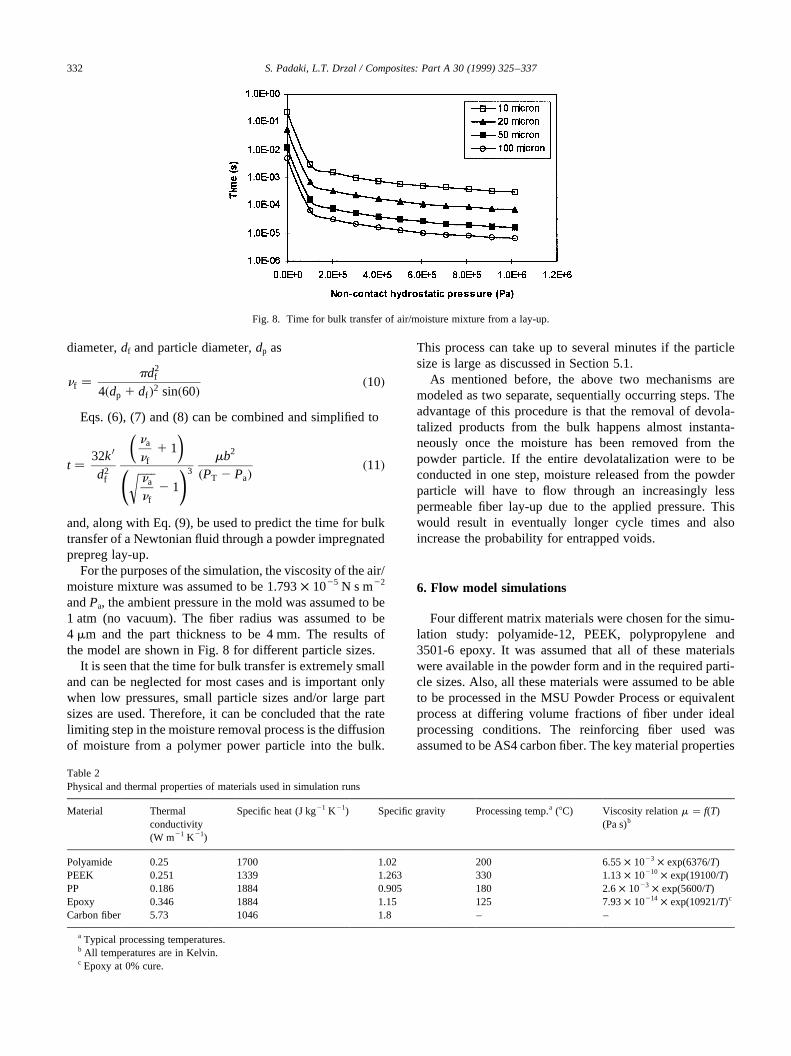
For the purposes of the simulation, the viscosity of the air/moisture mixture was assumed to be 1.793× 1025 N s m22
andPa, the ambient pressure in the mold was assumed to be1 atm (no vacuum). The fiber radius was assumed to be4 mm and the part thickness to be 4 mm. The results ofthe model are shown in Fig. 8 for different particle sizes.
It is seen that the time for bulk transfer is extremely smalland can be neglected for most cases and is important onlywhen low pressures, small particle sizes and/or large partsizes are used. Therefore, it can be concluded that the ratelimiting step in the moisture removal process is the diffusionof moisture from a polymer power particle into the bulk.
This process can take up to several minutes if the particlesize is large as discussed in Section 5.1.
As mentioned before, the above two mechanisms aremodeled as two separate, sequentially occurring steps. Theadvantage of this procedure is that the removal of devola-talized products from the bulk happens almost instanta-neously once the moisture has been removed from thepowder particle. If the entire devolatalization were to beconducted in one step, moisture released from the powderparticle will have to flow through an increasingly lesspermeable fiber lay-up due to the applied pressure. Thiswould result in eventually longer cycle times and alsoincrease the probability for entrapped voids.
6. Flow model simulations
Four different matrix materials were chosen for the simu-lation study: polyamide-12, PEEK, polypropylene and3501-6 epoxy. It was assumed that all of these materialswere available in the powder form and in the required parti-cle sizes. Also, all these materials were assumed to be ableto be processed in the MSU Powder Process or equivalentprocess at differing volume fractions of fiber under idealprocessing conditions. The reinforcing fiber used wasassumed to be AS4 carbon fiber. The key material properties
S. Padaki, L.T. Drzal / Composites: Part A 30 (1999) 325–337332
Fig. 8. Time for bulk transfer of air/moisture mixture from a lay-up.
Table 2Physical and thermal properties of materials used in simulation runs
Material Thermalconductivity(W m21 K21)
Specific heat (J kg21 K21) Specific gravity Processing temp.a (8C) Viscosity relationm � f(T)(Pa s)b
Polyamide 0.25 1700 1.02 200 6.55× 10²³ × exp(6376/T)PEEK 0.251 1339 1.263 330 1.13× 10210 × exp(19100/T)PP 0.186 1884 0.905 180 2.6× 10²³ × exp(5600/T)Epoxy 0.346 1884 1.15 125 7.93× 10214 × exp(10921/T)c
Carbon fiber 5.73 1046 1.8 – –
a Typical processing temperatures.b All temperatures are in Kelvin.c Epoxy at 0% cure.

of these materials needed for the simulation are listed inTable 2. The additional parameters that need to be specifiedfor the model are listed in Table 3. Some of these have beenexperimentally determined while others have been assumedor obtained from the literature.
The following processing variables were selected forstudy:
• particle Size (10, 20, 50, 100mm);• volume fraction (0.3–0.9);• matrix viscosity (related to processing temperature);• total pressure (calculated);• time (calculated).
Representative simulation runs were performed at differ-ent combinations of these variables for the four materialsidentified previously. The results of the simulation areshown in Fig. 9. Their interpretation is now discussed.
6.1. Effect of temperature
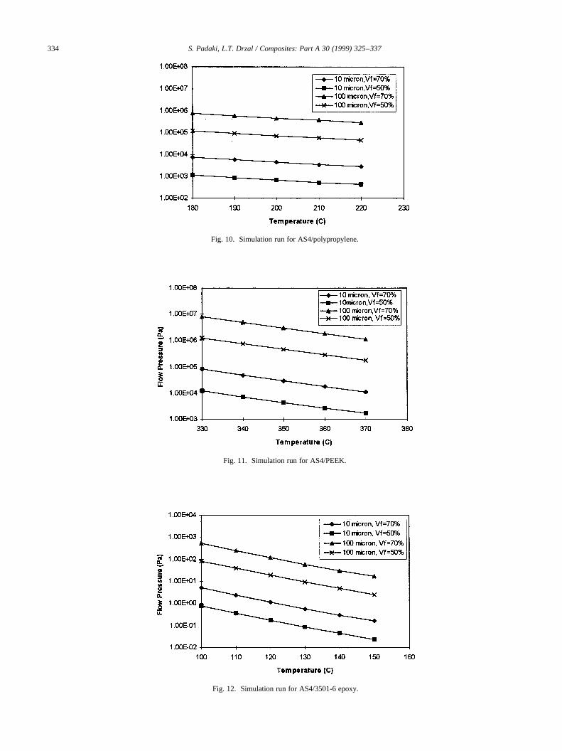
The processing temperature determines the viscosity ofthe material and significantly affects its flow characteristics.Simulations were performed for the different polymersystems at five different temperatures (all above themelttemperature of the polymer). It is seen that the pressure
required for polymer flow slightly decreases as the tempera-ture increases. This is because the viscosity of the materialdecreases exponentially. This is true for all the polymersthat are under consideration except that the absolute valuesdiffer based on the viscosity of the material. It should benoted that the effect of shear rate is neglected in the viscos-ity equation since an assumption of low mold closing rateshas been made.
6.2. Effect of particle size
The particle size affects the geometry of the tow. It iscoupled into the equations through the initial spacingbetween fibers. The results indicate that as the particlesize increases, the flow pressures increase for all composi-tions. This is because the particle have to be compressedthrough a greater distance. For example, the flow pressurerequired for the consolidation of the AS4/polyamide systemincreases by three orders of magnitude as the particle sizechanges by one order of magnitude (10–100mm). Themagnitude increase remains approximately the same asthe material system is changed. However, in the case ofhigher viscosity materials like PEEK, the pressures forflow are much larger when compared with the lower vis-cosity materials.
6.3. Effect of fiber volume fraction
The fiber volume fraction is an indirect measure of thetortuosity present in the composite. Higher volume fractionsdecrease the space available for polymer flow. This meansthat the pressures required for flow must be higher for highervolume fractions. This is shown by the simulations for thedifferent materials at two different fiber volume fractions,0.5 and 0.7 (Figs 9–12). Irrespective of the fiber/matrixsystem, increasing the fiber volume fraction from 0.5 to0.7 causes approximately an order of magnitude increasein the required flow pressure. As before, the increasing vis-cosity of the material causes the increase in the absolutevalues of the flow pressure.
S. Padaki, L.T. Drzal / Composites: Part A 30 (1999) 325–337 333
Table 3Values of simulation parameters
Quantity Value Reference
Initial temperature (8C) 25 –Heat transfer coefficient(W m22 K21)
225 Padaki [25]
Part thickness (mm) 2 –Fiber diameter (mm) 8 Hercules product literatureSpan-to-height ratio of fiber 350 Gutowskiet al. [30]Bending stiffness of fiber (Pa) 235× 109 Gutowskiet al. [30]Initial volume fraction of fiber 0.0085 Padaki [25]Maximum fiber volume fraction 0.9069 Padaki [25]Accuracy of thermocouple (8C) 0.5 –Cooling rate (8C min21) 10 –
Fig. 9. Simulation run for AS4/polyamide.
S. Padaki, L.T. Drzal / Composites: Part A 30 (1999) 325–337334
Fig. 10. Simulation run for AS4/polypropylene.
Fig. 11. Simulation run for AS4/PEEK.
Fig. 12. Simulation run for AS4/3501-6 epoxy.
7. Integration of simulation runs
7.1. Two-factor integration
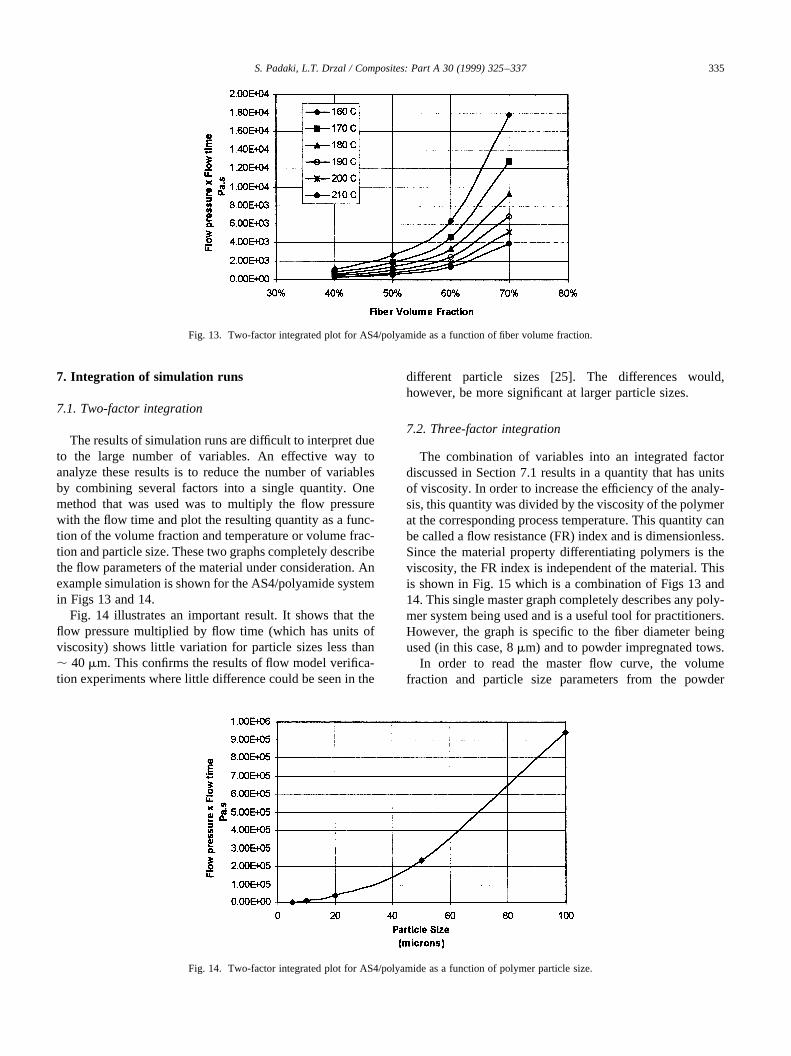
The results of simulation runs are difficult to interpret dueto the large number of variables. An effective way toanalyze these results is to reduce the number of variablesby combining several factors into a single quantity. Onemethod that was used was to multiply the flow pressurewith the flow time and plot the resulting quantity as a func-tion of the volume fraction and temperature or volume frac-tion and particle size. These two graphs completely describethe flow parameters of the material under consideration. Anexample simulation is shown for the AS4/polyamide systemin Figs 13 and 14.
Fig. 14 illustrates an important result. It shows that theflow pressure multiplied by flow time (which has units ofviscosity) shows little variation for particle sizes less than, 40mm. This confirms the results of flow model verifica-tion experiments where little difference could be seen in the
different particle sizes [25]. The differences would,however, be more significant at larger particle sizes.
7.2. Three-factor integration
The combination of variables into an integrated factordiscussed in Section 7.1 results in a quantity that has unitsof viscosity. In order to increase the efficiency of the analy-sis, this quantity was divided by the viscosity of the polymerat the corresponding process temperature. This quantity canbe called a flow resistance (FR) index and is dimensionless.Since the material property differentiating polymers is theviscosity, the FR index is independent of the material. Thisis shown in Fig. 15 which is a combination of Figs 13 and14. This single master graph completely describes any poly-mer system being used and is a useful tool for practitioners.However, the graph is specific to the fiber diameter beingused (in this case, 8mm) and to powder impregnated tows.
In order to read the master flow curve, the volumefraction and particle size parameters from the powder
S. Padaki, L.T. Drzal / Composites: Part A 30 (1999) 325–337 335
Fig. 13. Two-factor integrated plot for AS4/polyamide as a function of fiber volume fraction.
Fig. 14. Two-factor integrated plot for AS4/polyamide as a function of polymer particle size.

processing step are used to determine the FR index of thepolymer. Next, by knowing the processing temperature, theviscosity of the polymer is obtained and multiplied with theFR index. The resulting value is the product of the flow timeand flow pressure. By picking a flow time, a correspondingflow pressure can be determined. This pressure is added tothe fiber deformation pressure at the volume fraction ofinterest. This fiber pressure is shown graphically in Fig. 16.
To illustrate this process, an AS4/PEEK powder prepregconsolidation analysis is discussed below. Assuming thatthe prepreg to be consolidated has been prepared using20mm PEEK particles at a fiber volume fraction of 60%,the FR index value can be read off the graph and is equal to, 100. Knowing the viscosity of the PEEK at the processingtemperature of 3308C to be 6.5× 10³ Pa s, and assuming arapid flow time of 10 s, the required flow pressure is 0.65×10⁵ Pa. The fiber deformation pressure at this volumefraction is , 4 × 10⁵ Pa, resulting in a total required pres-sure of 4.65× 10⁵ Pa ( , 68 psi). Increasing the fiber
volume fraction to 70% causes the flow pressure to increaseto 1.95 × 10⁵ Pa and the fiber deformation pressure toincrease to 32× 105 Pa resulting in a total pressure of3.4 MPa (, 493 psi). This is a substantial increase thatcan be reduced by increasing the processing temperature.However, the total pressure can never be less than 3.2 MPa,the pressure required to deform the fiber network, and istherefore a constraint on the system.
The FR index can be thought of as a ratio of the flowlength of the polymer to the tortuosity of the tow. As before,increasing the fiber volume fraction increases the tortuosity,and hence the FR index. Similarly an increase in particlesize increases the flow length and correspondingly increasesthe FR index. Thus, a high index suggests a more difficultprocessing operation.
From the graph, it can be seen that a particle size of100mm is three orders of magnitude more difficult toprocess than a corresponding 10mm particle for the powderprocessing operation using AS4 carbon fiber tows.
S. Padaki, L.T. Drzal / Composites: Part A 30 (1999) 325–337336
Fig. 15. Three-factor integrated curve for flow-material independent fiber (diameter, 8mm).
Fig. 16. Fiber deformation pressure as a function of fiber volume fraction.

However, it should be emphasized that the pressure for flowis only a small fraction of the overall pressure required forthe consolidation step and is therefore not indicative of theoverall processability of the material. This fractionincreases with increased volume fraction, larger particlesize and increased matrix viscosity.
The total cycle time required can be obtained by addingthe flow time to the heat transfer times predicted by theheating and cooling model (almost material independent)and the kinetic times (which are material specific).
8. Conclusions
The following conclusions can be made as a result of thisstudy.
• The simulations show that small particle size powdersare advantageous to the consolidation of powder impreg-nated tapes.
• Two cases were considered in this study: (1) a non-hygroscopic polymer and (2) a hygroscopic polymer. Inboth cases, the time and pressure for flow increase withincreasing particle size.
• The amount of increase in time and pressure is directlyrelated to the viscosity of the polymer system used in thecomposite. For low viscosity matrix materials, the differ-ences in the flow times and pressures for different particlesizes are negligible. However, as more viscous polymersare used, the pressures and time scales increase signifi-cantly.
• Using a two-factor and three-factor integration approach,it has been shown that the flow model results can beconveniently viewed on a single chart. The ordinate ofthis chart is a dimensionless parameter termed the flowresistance (FR) index. High index values indicate agreater degree of difficulty in processing.
• In the case of hygroscopic polymers, an additional timeassociated with moisture removal has been considered.The results show that the time scales for bulk flow ofmoisture out of the lay-up are extremely small whencompared with times for moisture diffusion from thepolymer particle. The latter increases with increasingparticle size.
• A commercially viable processing scheme has also beensuggested based on the results of the model. It allows forthe rapid prototyping of parts using a mold clampingprocedure that eliminates press heating and coolingcycles.
Acknowledgements
The authors would like to acknowledge the financialsupport of the NSF Center for Low-Cost, High-Speed Poly-mer Composite Processing, Michigan State Universityduring the course of this study.
References
[1] Turton N, McAinsh J. Thermoplastic Compositions, US Patent No.3785916, 1974.
[2] Muzzy JD, Varughese B, Thammongkol V, Tincher W. Electrostaticprepregging of thermoplastic matrices. SAMPE J 1989;25(5):15–21.
[3] Lind DJ, Coffey VJ. UK Patent No. 1485586, 1977.[4] Carlsson LA. Thermoplastic Composite Materials. Amsterdam: Else-
vier Science Publishers, 1991.[5] Clemans SR, Western ED, Handermann AC. Thermoplastic hybrid
yarns for high-performance composites. Mater Eng 1988;105:27–30.[6] O’Connor JE. Reinforced Plastic, US Patent No. 4680224, July 1987.[7] Price RV. Production of Impregnated Roving. US Patent No.
3742106, June 1973.[8] Iyer SR. Continuous processing of unidirectional prepreg. Ph.D.
dissertation, Michigan State University, 1990.[9] Visser J. Powder Technol 1989;58:1–10.
[10] Ganga RA. Procede de Fabrication d’Objects Composites Obtenus.French Patent No. 2548048-A1, 1983.
[11] Brown AW, Moran RJ. Apparatus for Impregnating Strands, Webs,Fabrics and The Like. US Patent No. 3,817,211, 1974.
[12] Muzzy JD, Varughese B. Flexible Multiply Towpreg and Method ofProduction Thereof. US Patent No. 5,094,883, 1992.
[13] Sun Z, Morgan RJ, Lewis DN. Advanced Composite Materials: NewDevelopments and Applications, Detroit (Conf. Proc.), 1991.
[14] Duvall MS, Ramani K. In situ composite manufacture using an elec-trostatic powder spray process and filament winding. Polym PolymCompos 1996;4(5):325–334.
[15] Iyer SR, Drzal LT. J Thermoplast Compos Mater 1990;3:25–355.[16] Iyer SR, Drzal LT, Jayaraman K. Method for Coating Fibers with
Particles by Fluidization in a Gas. US Patent No. 5,102,690, 1992.[17] Iyer SR, Drzal LT, Jayaraman K. Method for Coating Fibers with
Particles By Fluidization in a Gas. US Patent No. 5,123,373, 1992.[18] Iyer SR, Drzal LT, Jayaraman K. Method for Fiber Coating with
Particles. US Patent No. 5,128,199, 1992.[19] Vyakarnam MN, Drzal LT. Apparatus and High Speed Method for
Coating Elongated Fibers. US Patent No. 5,310,582, 1994.[20] Vyakarnam MN, Drzal LT. Polymer Processing Society (Conf.
Proc.), 1992: 31-32.[21] Allen LE, Edie DD, Lickfield GC, McCollum JR. J Thermoplast
Compos Mater 1988;1:371–379.[22] Baucom RM, Snoha JJ, Marchello JM. Process for Application of
Powder Particles to Filamentary Materials. US Patent No.5,057,338, 1991.
[23] Baucom RM, Marchello JM. SAMPE International Symposium(Conf. Proc.), 1993;38:1902–1915.
[24] Ogden AL, Hyer MW, Wilkes GM, Loos AC. J Thermoplast ComposMater 1992;5:14–31.
[25] Padaki S. A process and consolidation model for polymer powderimpregnated composite tapes. Ph.D. dissertation, Michigan StateUniversity, 1995.
[26] Padaki S, Drzal LT. A consolidation model for polymer powderimpregnated composite tapes. J Compos Mater 1997;31(21):2202–2227.
[27] Willet JL. Water sorption and diffusion in starch/polyolefin blends.Polym Eng Sci 1995;35(14):1184–1190.
[28] Astrom BT, Pipes RB, Advani SG. On flow through aligned fiber bedsand its application to composite processing. J Compos Mater1992;26(9):1351–1373.
[29] Yang H, Colton JS. Microstructure-based processing parameters ofthermoplastic composite materials. Part II: Experimental results.Polym Compos 1994;15(1):42–45.
[30] Gutowski TG, Cai Z, Bauer S, Boucher D, Kingery J, Wineman S.Consolidation experiments for laminate composites. J Compos Mater1987;21:651–669.
S. Padaki, L.T. Drzal / Composites: Part A 30 (1999) 325–337 337