
A simplified approach to estimating reference source terms for ...
73
IAEA-TECDOC-1127 XA9953383 A simplified approach to estimating reference source terms for L WR designs INTERNATIONAL ATOMIC ENERGY AGENCY /A December 1999 30-50
-
Upload
khangminh22 -
Category
Documents
-
view
1 -
download
0
Transcript of A simplified approach to estimating reference source terms for ...
IAEA-TECDOC-1127XA9953383
A simplified approach to estimatingreference source terms for
L WR designs
INTERNATIONAL ATOMIC ENERGY AGENCY /A
December 1999
3 0 - 5 0
The originating Section of this publication in the IAEA was:
Engineering Safety SectionInternational Atomic Energy Agency
Wagramer Strasse 5P.O. Box 100
A-1400 Vienna, Austria
The IAEA does not normally maintain stocks of reports in this series. However, electroniccopies of these reports can be obtained from:
INIS ClearinghouseInternational Atomic Energy AgencyWagramer Strasse 5P.O. Box 100A-1400 Vienna, Austria
Telephone: (43) 1 2600-22880 or 22866Fax: (43) 1 2600-29882E-mail: [email protected] site: http://www.iaea.org/programmes/inis/inis.htm
Orders should be accompanied by prepayment of 100 Austrian Schillings in the form of acheque or credit card (MasterCard, VISA).
A SIMPLIFIED APPROACH TO ESTIMATINGREFERENCE SOURCE TERMS FOR LWR DESIGNS
IAEA, VIENNA, 1999IAEA-TECDOC-1127
ISSN 1011-4289
©IAEA, 1999
Printed by the IAEA in AustriaDecember 1999
IAEA SAFETY RELATED PUBLICATIONS
IAEA SAFETY STANDARDSUnder the terms of Article III of its Statute, the IAEA is authorized to establish standardsof safety for protection against ionizing radiation and to provide for the application of thesestandards to peaceful nuclear activities.
The regulatory related publications by means of which the IAEA establishes safetystandards and measures are issued in the IAEA Safety Standards Series. This seriescovers nuclear safety, radiation safety, transport safety and waste safety, and also generalsafety (that is, of relevance in two or more of the four areas), and the categories within itare Safety Fundamentals, Safety Requirements and Safety Guides.
• Safety Fundamentals (silver lettering) present basic objectives, concepts andprinciples of safety and protection in the development and application of atomicenergy for peaceful purposes.
• Safety Requirements (red lettering) establish the requirements that must be met toensure safety. These requirements, which are expressed as 'shall' statements, aregoverned by the objectives and principles presented in the Safety Fundamentals.
• Safety Guides (green lettering) recommend actions, conditions or procedures formeeting safety requirements. Recommendations in Safety Guides are expressed as'should' statements, with the implication that it is necessary to take the measuresrecommended or equivalent alternative measures to comply with the requirements.
The IAEA's safety standards are not legally binding on Member States but may be adoptedby them, at their own discretion, for use in national regulations in respect of their ownactivities. The standards are binding on the IAEA for application in relation to its ownoperations and to operations assisted by the IAEA.
OTHER SAFETY RELATED PUBLICATIONSUnder the terms of Articles HI and VIII.C of its Statute, the IAEA makes available andfosters the exchange of information relating to peaceful nuclear activities and serves as anintermediary among its members for this purpose.
Reports on safety and protection in nuclear activities are issued in other series, in particularthe IAEA Safety Reports Series, as informational publications. Safety Reports maydescribe good practices and give practical examples and detailed methods that can be usedto meet safety requirements. They do not establish requirements or makerecommendations.
Other IAEA series that include safety related sales publications are the Technical ReportsSeries, the Radiological Assessment Reports Series and the INSAG Series. The IAEAalso issues reports on radiological accidents and other special sales publications. Unpricedsafety related publications are issued in the TECDOC Series, the Provisional SafetyStandards Series, the Training Course Series, the IAEA Services Series and theComputer Manual Series, and as Practical Radiation Safety and Protection Manuals.

FOREWORD
The IAEA has initiated an extensive programme to review and bring up to date thecomplete set of the Standards (Codes and Guides) of the Nuclear Safety Series (NUSS). Themain reason behind this is to make all the Standards consistent with the Safety FundamentalsSafety Series No. 110 "The Safety of Nuclear Installations", which represents the top levelpublication in the hierarchy of the IAEA Safety Series. The work has begun and is expected tobe concluded by the year 2000.
The revision of the standards which address the design process is of particular interestbecause of its impact on the design of the next generation of reactors. This programme wasinitiated at the IAEA in 1991 following the recommendations of the General Conference. Thefirst task, preparing safety objectives and principles for future reactors, has been completedand its results published in IAEA-TECDOC-801 "Development of Safety Principles for theDesign of Future Nuclear Power Plants".
The substantial innovation proposed in TECDOC-801 is that severe accidents must beexplicitly considered in the design of future NPPs to ensure that the impact on individuals andthe environment beyond the site fence is limited to an acceptably low level.
Since TECDOC-801 reflects the quite general consensus that severe accidents must beconsidered explicitly in the design of future plants, the IAEA has decided to devote asignificant amount of resources to the identification of safety issues associated with severeaccidents which should be addressed in the design of future NPPs.
As limiting the need for off-site countermeasures is an objective in many countries whenconsidering the designs of future NPPs, work has been initiated on the evaluation of thequantity of fission products that is available for leakage from the containment in the case ofsevere accident sequences that should be used for design purposes. This was considered anecessary input for the design of the containment and its associated systems.
The publication of this IAEA technical document represents the conclusion of a task,initiated in 1996, devoted to the estimation of the radioactive source term in nuclear reactors.It focuses mainly on light water reactors (LWRs).
The IAEA is grateful to the experts who contributed to this publication. The majorcontributors were M.C. Dutton (NNC Limited, UK), T. Kress (Kress Associates, USA),J. Eyink (Nuclear Power International) and C. Benson (AEA Technology, UK) who provideda comprehensive review. The officer of the IAEA responsible for the TECDOC wasM. Gasparini of the Division of Nuclear Installation Safety.

EDITORIAL NOTE
In preparing this publication for press, staff of the IAEA have made up the pages from theoriginal manuscript(s). The views expressed do not necessarily reflect those of the IAEA, thegovernments of the nominating Member States or the nominating organizations.
Throughout the text names of Member States are retained as they were when the text wascompiled.
The use of particular designations of countries or territories does not imply any judgement bythe publisher, the IAEA, as to the legal status of such countries or territories, of their authorities andinstitutions or of the delimitation of their boundaries.
The mention of names of specific companies or products (whether or not indicated asregistered) does not imply any intention to infringe proprietary rights, nor should it be construed asan endorsement or recommendation on the part of the IAEA.
CONTENTS
1. INTRODUCTION 1
1.1. Background 11.2. Ojective 11.3.Sope 2
2. SOURCE TERM TO THE CONTAINMENT 4
2.1. Fuel design and core inventory 42.2. Methodology and codes for determination of the fission product and actinide
inventory 42.3. Uncertainties 4
3. THERMAL HYDRAULICS AND CORE DEGRADATION CONSIDERATIONS 5
3.1. Generalized thermal hydraulic algorithm 63.1.1. Time to start of core uncovery 73.1.2. The fraction of core involvement as a function of time 83.1.3. The initial heat-up rate 93.1.4. Heat-up rate due to runaway Zr oxidation 9
3.2. Uncertainties 10
4. IN-VESSEL SOURCES 10
4.1. Fission product/aerosol release 104.1.1. Introduction 104.1.2. Chemical forms 114.1.3. Control rod and structural release 124.1.4. In-vessel melt retention strategies 134.1.5. Reflood 14
4.2. Uncertainties 14
5. EFFECTS OF THE RCS ON FISSION PRODUCT BEHAVIOUR 14
6. EX-VESSEL SOURCES 14
6.1. Molten core-concrete interactions (MCCI) 156.2. Release from molten pools 166.3. Fuel—coolant interaction (FCI) and direct containment heating (DCH) 166.4. Additional ex-vessel phenomena 17
7. IN-CONTAINMENT BEHAVIOUR OF FISSION PRODUCTS 18
7.1. Introduction 187.2. In-containment aerosol behaviour algorithms 19
7.2.1. Agglomeration and gravitational settling 197.2.2. Spray removal of aerosols 227.2.3. Pool scrubbing decontamination factors 237.2.4. Containment coolers 247.2.5. Major uncertainties and R&D requirements in aerosol behaviour 24
7.3. Iodine behaviour including pH control 247.3.1. Introduction 24
7.3.2. Phenomena 257.3.3. pH control 267.3.4. Computer codes 277.3.5. Uncertainties and R&D requirements 28
8. SPECIFICS OF NEW GENERATION DESIGNS 29
8.1. General concepts of new generation plants 298.2. Specific characteristics of new generation plants (AP600, EPR, simplified BWR,
and WWER-640) which affect the source term 308.2.1. Specific characteristics of the AP600 308.2.2. Specific characteristics of the EPR 318.2.3. Specific characteristics of a simplified BWR 328.2.4. Specific characteristics of the WWER-640 32
8.3. Evolutions in fuel and core designs 34
9. CONCLUSIONS 34
9.1. Fuel design and core inventory 359.2. Thermal hydraulics and core degradation considerations 359.3. In-vessel sources 359.4. Effects of the RCS on fission product behaviour 369.5. Ex-vessel sources 369.6. In-containment behaviour 36
9.6.1. Important phenomena 369.6.2. Major uncertainties 37
9.7. The design of new generation plants and fuels 37
REFERENCES 39
APPENDIX: APPLICATION EXAMPLE FOR THE SIMPLIFIED SOURCETERM METHODOLOGY 43
ANNEX: CODE LISTINGS AND CALCULATION RESULTS 57
1. INTRODUCTION
1.1. BACKGROUND
The amount of fission products that can be released from a nuclear power plant in anaccident is a fundamental parameter to estimate the consequences of the accident onindividuals and environment.
The regulatory environment and industrial expectations vary in different countries.There is, however, a clear convergence on the need to define a reference quantity, called either"source term" or "in-containment source term".
This source term, which is defined as the timing, fraction, speciation of fission productsreleased to the containment during a severe accident and their behaviour when they aresuspended in the containment atmosphere, is intended to be used for:
— assessing the robustness of the containment to contain fission products,
— assessing external consequences to demonstrate compliance with deterministic criteria,
— designing some containment systems,
— defining conditions for the environmental qualification and assessing the survivability ofkey components,
— providing adequate protection from direct radiation for the operating staff in the controlroom and in other areas where access is required.
This source term must be such that the regulators and the industry have a highconfidence that the containment systems and safety related structures and components, whichare designed using this source term, will result in an acceptable level of safety. Thus, it isrequired to be reasonably representative for all the risk dominant sequences that involve apartial or total melting of the core.
The work that the IAEA is carrying out on source terms is considered to make avaluable contribution to the subject by promoting the exchange of information and theharmonization of views. It is considered that it will significantly contribute to the revision ofthe IAEA NUSS standards.
1.2. OBJECTIVE
This report focuses on the source term for light water reactors.
For the purposes of this report, the expression 'source term' is defined as follows:
(a) Source term to the containment is the magnitude, physical and chemical form andtiming of the release of fission products and other aerosols from core materials andconcrete to the primary containment atmosphere or to the suppression pool from bothin- and ex-vessel sources.
(b) In-containment source term is the airborne radioactivity and its physical and chemicalform in the atmosphere of the primary containment as a function of time. Thus, the in-containment source term is the radioactivity that is available to be released from theprimary containment.
The first of these definitions represents the material that is released into the containmentfrom both the reactor coolant circuit and ex-vessel sources, while the second definitionrepresents the behaviour of that material in the containment.
The most important barrier to the release of fission products to the environment is thecontainment. To mitigate the consequences of severe accidents, it is important that thecontainment maintain its capability as an effective barrier and that the combination of thefission product activity in the containment that is available for release (the airborne activity orin-containment source term) and the performance of the containment systems result inacceptable radiological consequences as defined in IAEA-TECDOC-801 for new generationplants.
With respect to releases to the environment, three important issues need to be addressed:
— the source term to containment and the in-containment source term as defined above,
— the performance of the containment in withstanding the severe accident loads and theresultant leakage of fission products,
— the pathway for fission-products to escape from the containment and the associateddepletion due to the secondary containment, the filters and the stack.
Only the first is the subject of the present report. The other two (and possibly a fourthwhich may address the demonstration of compliance with regulatory acceptance criteria andthus deals with dose calculations) will be the subject of future work.
The third aspect is important because European NPPs differ not only in theircontainment design but also in the extent to which the primary containment is enclosed byadjacent buildings such as a secondary containment and the auxiliary buildings. If thecontainment fails or leaks, the release of fission products will not be directly into theatmosphere but into the adjacent buildings. Because these buildings are relatively cold andhave large surface areas, a significant additional depletion of aerosols and gaseous iodine canbe expected, depending on the residence time and, in general, any extract to the environmentwill be via filters. It is therefore necessary to consider carefully the release paths in order toquantify the release and to assess the accident management procedures, such as activating fansand filtered release paths.
The objectives of the present report are:
(1) To identify the main aspects associated with new generation plant designs which couldsignificantly affect the source term to the containment.
(2) To identify the worldwide methodologies (codes and models) for evaluating the effect ofthese design aspects on the source term to the containment and the airborne activity inthe containment atmosphere.
(3) To identify the major uncertainties which affect the source term to the containment andthe airborne activity in the containment atmosphere.
(4) To identify the R&D requirements needed to address these uncertainties for newgeneration NPPs.
(5) To determine the usefulness of providing guidance on how a reference source term tothe containment could be evaluated parametrically based on simple algorithms and, ifuseful, describe such algorithms as far as practicable.
1.3. SCOPE
The scope of this report is to provide regulatory bodies, utilities and vendors with asimple means for evaluating a source term, both to and in the containment, which provides areasonably bounding envelope for the risk-dominant sequences that are applicable to thedesign being considered. This is relevant to both existing and future reactor designs.
Events at shutdown may contribute significantly to the overall core melt frequency.With respect to the release into the containment, they are bounded by the events at powerbecause, in both cases, the temperature excursion is the same, driven by the Zr oxidation rateand not by the decay heat.
This report does not address the release of radioactivity via paths that by-pass theprimary containment structure since the consideration of by-pass paths does not affect thedesign of the primary containment systems. They will, however, affect the design of localcontainment systems outside the primary and secondary containments and will need to beaddressed separately for this purpose. It is anticipated that the designs of future plants willreduce the frequency of by-pass faults involving a core melt to low levels.
It is considered that specifying a single source term for all light water reactors is notappropriate, due to the wide variety of design features, fuels and cores in future designs.However the following are proposed for any individual plant:
— A reference sequence which has the necessary attributes to derive a numerical referencesource term;
— the identification and a description of the relevant core degradation mechanisms forreference sequence do not take credit for accident management other thandepressurizing the primary circuit before the vessel fails;
— simple algorithms for the evaluation of the melt progression, the quantification ofreleases to the containment; and
— their speciation and behaviour in the containment for the reference sequence.
As engineering judgement must be exercised due to the complexity of phenomena andall the associated uncertainties, guidance is also provided on the following:
— the remaining uncertainties and sensitivity analyses that are needed to assess the results;and
— the computer codes available which can also be used to predict the in-containmentsource term for those situations for which simple algorithms are inadequate.
In developing the source term, the following considerations are taken into account:
— the loss of all permanent sources of water to the reactor coolant system (RCS) apartfrom pressurized vessels, such as the accumulators, is assumed, as otherwise therewould not be a core melt;
— future designs are expected to provide a robust and reliable means for depressurizing thereactor coolant system;
— the application of the proposed algorithms should be straightforward.
The proposed reference sequence for deriving the reference source term is a lowpressure core melt sequence in which the reactor coolant system is depressurized well beforethe reactor pressure vessel fails. This approach is consistent with the risk dominant sequencesthat have been identified in plant assessments [1-5].
The evaluation of the proposed reference source term contains simplifying assumptions.However, these should be modified on the basis of engineering judgement in cases where theywould otherwise lead to a less robust design. For example, the derived timing of theblow down should not be used to justify less reliable or slower reacting containment isolationvalves.
2. SOURCE TERM TO THE CONTAINMENT
2.1. FUEL DESIGN AND CORE INVENTORY
Although the quantification of the source term is generally expressed in terms of thefractions of all the relevant radionuclides, the utilization of these fractions for variouspurposes requires that they be converted into actual quantities using the fission-product andactinide inventories of the core.
These data are not expected to be the same for all plants, even if they have the samedesign. Design parameters such as the core thermal output, the maximum burnup of the fuel,the type of fuel (e.g. UO2 or MOX), may have a significant impact on the inventory of all therelevant radionuclides. Thus, in the analysis of accidents for the purposes of designing thecontainment, a bounding inventory should be evaluated which anticipates the likely changes tothe core and fuel design or management over the lifetime of the plant, which may be up to 60years.
2.2. METHODOLOGY AND CODES FOR DETERMINATION OF THE FISSIONPRODUCT AND ACTINIDE INVENTORY
The evaluation of the core inventory is a complex process, which has at least twoobjectives that are relevant to this report, namely:
— to provide the necessary data for quantifying the source term by using simple algorithmsor computer codes (examples of these data are the decay heat or the power distributionin the core);
— to provide the absolute magnitude of the maximum radioactivity which is required thatis available in the core to be released to the containment in order to demonstratecompliance with the defined acceptance criteria, for equipment qualification and fordemonstrating equipment survivability.
To evaluate these quantities, the assumption is made that the accident occurs at the endof an equilibrium fuel cycle.
Systematic studies are required to define the fuel loading patterns that are compatiblewith the fuel design limits and, based on these to derive the maximum inventories of therelevant fission products and actinides (i.e. those that will contribute significantly to the decayheat or the environmental consequences). This process is similar to that performed by a fueldesigner when optimizing his product.
Although simple algorithms and approximate methods have been used in the past forsuch evaluations, it is recommended that the inventory be evaluated using a well validatedcomputer code together with a critically assessed and internationally accepted database.
Examples of such codes, which have typically been validated for the core and fueldesigns and fuel management strategies are ORIGEN (USA), APOLLO (France) and FISPIN(UK).
2.3. UNCERTAINTIES
In addition to the uncertainties associated with the conditions for which the codes havebeen validated, there are uncertainties associated with (a) the potential evolution of the designof the core and fuel and the fuel management strategy, and (b) the limited database againstwhich the codes are validated. However, these uncertainties in predicting the fission productinventory are small compared to the uncertainties in estimating the fission product release
from the primary circuit and are negligible compared to those associated with evaluating thefission product distribution within the containment.
Some middle term to long term developments in the design of fuel as described inSection 8.3 have the potential for significantly affecting the quantification of the inventory.
Examples of possible developments are:
— increased burnup,— extended use of MOX fuel,— extended use of burnable poisons and new burnable poisons,— new control rod designs,— new types of fuel, and— changes to the dimensions and material of the cladding, spacers, etc.
3. THERMAL HYDRAULICS AND CORE DEGRADATIONCONSIDERATIONS
Generally, the determination of the source term requires a knowledge of the thermal-hydraulic progression that leads to the coolant boiling off, and the subsequent core heat-up,melting and degradation. For such information, use has traditionally been made of computercodes that model the core and primary circuit as finite elements and include such phenomenaas steam/Zr chemical reactions, ZrO2-uranium dissolution and fission product/aerosol release.These codes have been partially validated using experiments carried out under the relevantconditions, but there are still significant uncertainties.
It is clear that plant and sequence specific source terms could be developed for futureplants after their designs have been specified by using such codes to analyse a range ofrelevant accident sequences. The selection of a bounding case among these could be anappropriate way to proceed to develop design specific source terms provided that sufficientguidance is available on what constitutes a "valid" code along with guidance on how to makethe key assumptions that are required for the application of such codes, which sequences needevaluating for the purposes of designing the containment systems, how the results should beinterpreted and how sensitivity/uncertainty analyses should be utilized.
While such a procedure should be acceptable, it amounts to a case-by-casedetermination that is done after the design of the RCS is complete. Guidance would still berequired on which sequences are appropriate for use in comparing with regulatory dosecriteria, which codes can be certified for such use, and how to quantify the uncertainties andinterpret the results. This procedure will give the designer or the regulator little prior guidanceas to what is likely to be an acceptable design basis source term.
One of the objectives of this report is to explore the feasibility of developing simple, butrobust, algorithms (or an algorithmic methodology) that can capture the essence of thethermal-hydraulic behaviour of future plants related to their important (to source terms) designdifferences without having to resort to such large complex codes. Such algorithms should beuseful to both regulators and designers as they easily accommodate readjustments anddifferent design options. They can make clear the extent of the effects that different designoptions have on the source term.
The purpose of developing source term algorithms, as advocated here, is to have aneasily applied, consistent and transparent means to give sufficient guidance (quantity and
timing of fission product releases) to designers and regulators as to whether or not a specificdesign is likely to meet regulatory requirements that involve the use of a design basis sourceterm.
A primary requirement for such a design basis source term is that it should be able toresult in a containment design that would provide "defence in depth" to compensate for thelack of knowledge on calculating risk or lack of confidence in the ability to terminateaccidents before they lead to extensive core damage. Almost by definition, a reference sourceterm must be based on a low probability sequence involving failure of the ECCS (whetheractive or passive) to terminate the accident sequence and which would allow a major degreeof core melt. Thus, the choice of the type of sequence (or sequences) to use to developrepresentative source terms for design basis is largely a matter of judgement and experience asto what would result in a sufficiently robust containment design.
Experience has shown that low pressure LOCA sequences generally develop faster thanhigh-pressure sequences and will release equally significant amounts of fission products.Since it is expected that future LWRs will utilize a strategy of depressurization for all accidentsequences in order to avoid high pressure melt ejection events, it is judged that an appropriatechoice for developing a representative design basis source term is a depressurized sequence(to give the fastest timing), coupled with sufficient conservatism in the heat-up transient togive fission product releases that are appropriately large for design basis use. The"appropriateness" would be related to both the probabilities and source term quantitiesassociated with the spectrum of severe accidents sequences. The overall objective, of course,is to end up with a design that leads to an acceptable risk but which also provides a sufficientdegree of confidence that any fission products released from the fuel in the unlikely event ofan accident will be adequately contained.
3.1. GENERALIZED THERMAL HYDRAULIC ALGORITHM
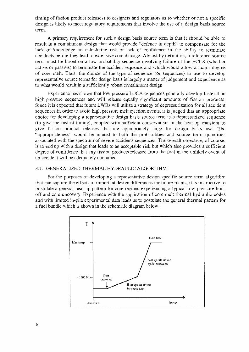
For the purposes of developing a representative design specific source term algorithmthat can capture the effects of important design differences for future plants, it is instructive topostulate a general heat-up pattern for core regions experiencing a typical low pressure boil-off and core uncovery. Experience with the application of core-melt thermal hydraulic codesand with limited in-pile experimental data leads us to postulate the general thermal pattern fora fuel bundle which is shown in the schematic diagram below.
Max
T '
temp. —
1500 K —
shutdown
Coreuncovery
Holdtime
/ heat up rate/ byZr oxida
Heat up rate drivenby decay heat
drivention
time
This, of course, is a "stylized" representation that does not recognize severalcomplicated features of core degradation behaviour such as the mechanics of fuel dissolution,relocation and blockage. Nevertheless, it is considered that such a representation provides asimple vehicle that, when applied with the appropriate fission product release modelling, willresult in a representative source term that can readily account for the important designdifferences that might exist in future plants. Such a generalized pattern can be extended towhole core behaviour if a specification is also made for the fraction of the core that enters thistransient as a function of time.
Whilst the temperature profile of the core will not be uniform, a simplified approach isto assume that the whole core will behave in the same way as the fuel pin. This can affect thetiming of the release, as well as the magnitude of the overall source term to the containment.However, treating all parts of the core as behaving in this way simultaneously is conservativewith respect to the timing and magnitude of the source term. Therefore additionalconservatism can be incorporated into the algorithm by choosing a sufficiently high value forthe "maximum temperature before relocation" (i.e. the maximum temperature applied to thewhole core, and a sufficiently long "hold time" (i.e. the length of time for which the core is atthis temperature). Slower heat-up transients are known to release more fission products thando rapid transients. Therefore, the selection of the "maximum temperature" and the "holdtime" needs to be such that the resulting fission product release is also representative of theslower sequences. The appropriate selection of these parameters is largely a matter ofjudgement. The "test" for sufficiency in the conservatism provided by the recommendedvalues in this section is to compare the magnitude of the resulting source term with one thathas been developed from the full range of sequences using an equivalent release model. Thiswas performed in the Appendix to this report by comparing the NUREG-1465 [6] PWRvalues with the results of the algorithms in the last two columns of Table A.4. Thiscomparison indicates that the values selected for a maximum temperature of 2960 K and zerohold time are sufficiently conservative for the volatile elements, which are the mostradiologically significant.
Thus, simple but robust algorithms are proposed in which these parameters can beincorporated to envelope their effects on quantifying the generalized thermal transient patternand how that can be converted directly into release timing and quantities. To convert thegeneralized thermal transient into fission-product release, the following input is required:
(1) The Zr oxidation runaway heat-up rate;
(2) The maximum temperature reached in the transient;
(3) The hold time at the maximum temperature. Using these data, the algorithms need toquantify the following elements associated with the generalized thermal transient;
(4) The fraction of the core entering the generalized thermal transient as a function of time;
(5) The time to uncovery of the core;
(6) The initial heat-up rate and associated timing;
(7) The fission product/aerosol release rates throughout the transient.
3.1.1. Time to start of core uncovery
Core uncovery during a depressurization accident occurs after the choked-flowblowdown of the coolant through either the break and/or the depressurisation system followedby both drainage of the primary system coolant out of the break and boiling away of theresidual coolant.
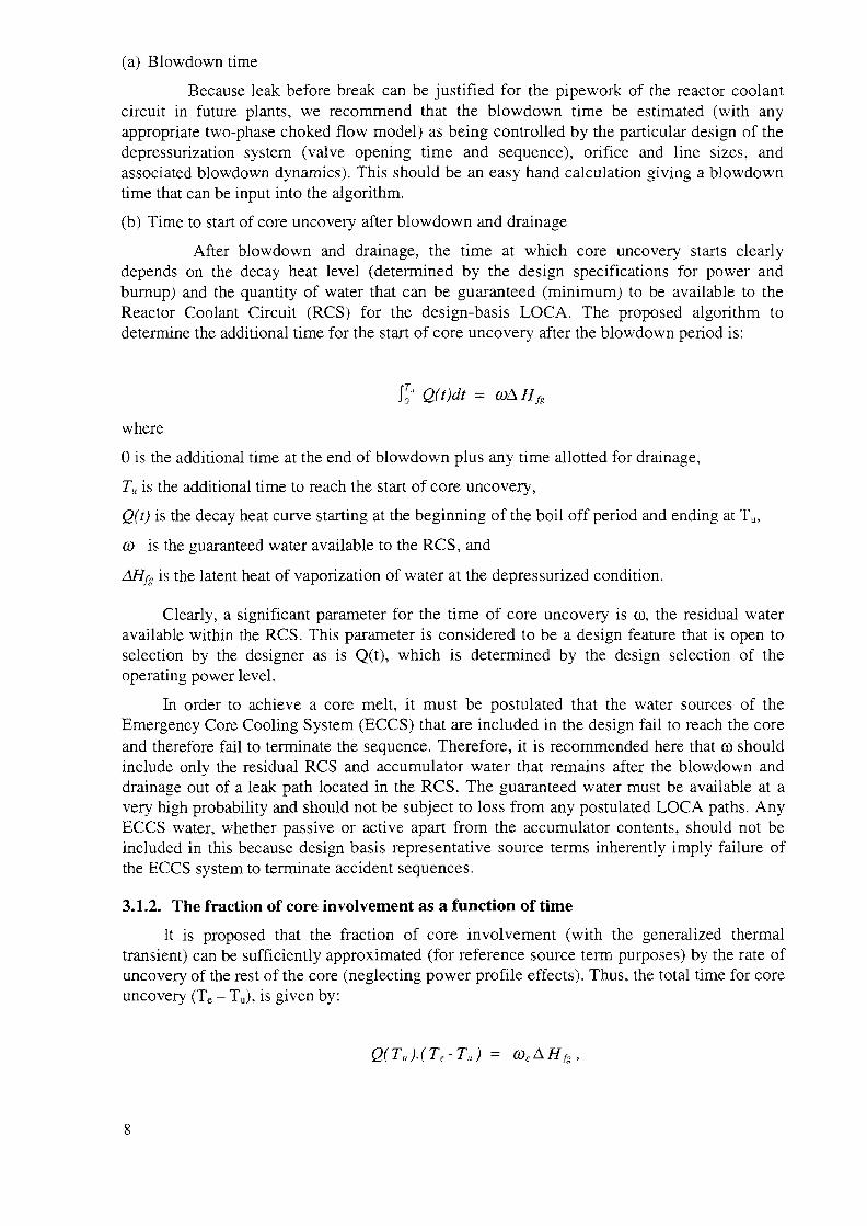
(a) Blowdown time
Because leak before break can be justified for the pipework of the reactor coolantcircuit in future plants, we recommend that the blowdown time be estimated (with anyappropriate two-phase choked flow model) as being controlled by the particular design of thedepressurization system (valve opening time and sequence), orifice and line sizes, andassociated blowdown dynamics). This should be an easy hand calculation giving a blowdowntime that can be input into the algorithm.
(b) Time to start of core uncovery after blowdown and drainage
After blowdown and drainage, the time at which core uncovery starts clearlydepends on the decay heat level (determined by the design specifications for power andburnup) and the quantity of water that can be guaranteed (minimum) to be available to theReactor Coolant Circuit (RCS) for the design-basis LOCA. The proposed algorithm todetermine the additional time for the start of core uncovery after the blowdown period is:
\To Q(t)dt = coAHfs
where
0 is the additional time at the end of blowdown plus any time allotted for drainage,
Tu is the additional time to reach the start of core uncovery,
Q(t) is the decay heat curve starting at the beginning of the boil off period and ending at Tu,
co is the guaranteed water available to the RCS, and
AHfg is the latent heat of vaporization of water at the depressurized condition.
Clearly, a significant parameter for the time of core uncovery is co, the residual wateravailable within the RCS. This parameter is considered to be a design feature that is open toselection by the designer as is Q(t), which is determined by the design selection of theoperating power level.
In order to achieve a core melt, it must be postulated that the water sources of theEmergency Core Cooling System (ECCS) that are included in the design fail to reach the coreand therefore fail to terminate the sequence. Therefore, it is recommended here that co shouldinclude only the residual RCS and accumulator water that remains after the blowdown anddrainage out of a leak path located in the RCS. The guaranteed water must be available at avery high probability and should not be subject to loss from any postulated LOCA paths. AnyECCS water, whether passive or active apart from the accumulator contents, should not beincluded in this because design basis representative source terms inherently imply failure ofthe ECCS system to terminate accident sequences.
3.1.2. The fraction of core involvement as a function of time
It is proposed that the fraction of core involvement (with the generalized thermaltransient) can be sufficiently approximated (for reference source term purposes) by the rate ofuncovery of the rest of the core (neglecting power profile effects). Thus, the total time for coreuncovery (Te - Tu), is given by:
Q(Tu).(Te-Tu) = cocAHfg,
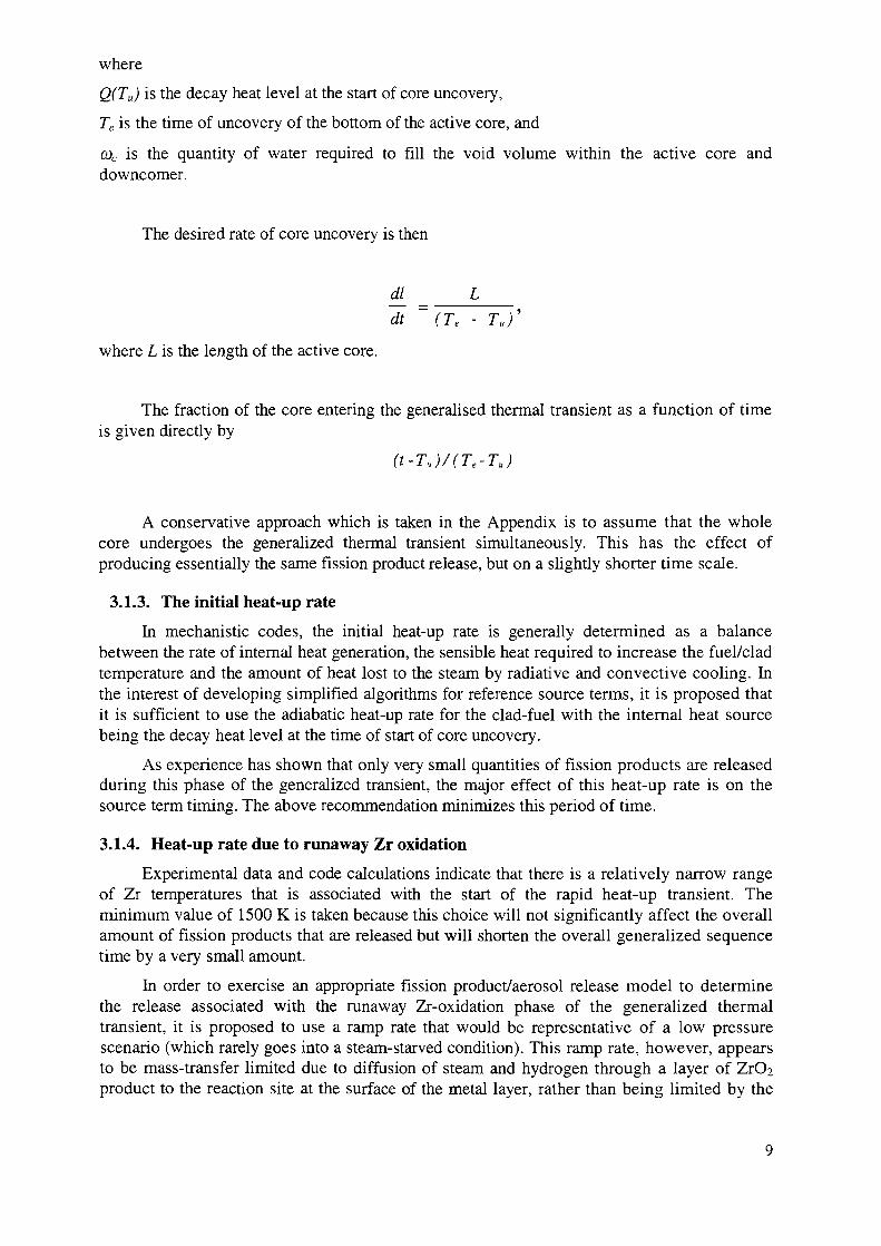
where
Q(TU) is the decay heat level at the start of core uncovery,
Te is the time of uncovery of the bottom of the active core, and
0)c is the quantity of water required to fill the void volume within the active core anddowncomer.
The desired rate of core uncovery is then
where L is the length of the active core.
The fraction of the core entering the generalised thermal transient as a function of timeis given directly by
(t-Tu)/(Te-TJ
A conservative approach which is taken in the Appendix is to assume that the wholecore undergoes the generalized thermal transient simultaneously. This has the effect ofproducing essentially the same fission product release, but on a slightly shorter time scale.
3.1.3. The initial heat-up rate
In mechanistic codes, the initial heat-up rate is generally determined as a balancebetween the rate of internal heat generation, the sensible heat required to increase the fuel/cladtemperature and the amount of heat lost to the steam by radiative and convective cooling. Inthe interest of developing simplified algorithms for reference source terms, it is proposed thatit is sufficient to use the adiabatic heat-up rate for the clad-fuel with the internal heat sourcebeing the decay heat level at the time of start of core uncovery.
As experience has shown that only very small quantities of fission products are releasedduring this phase of the generalized transient, the major effect of this heat-up rate is on thesource term timing. The above recommendation minimizes this period of time.
3.1.4. Heat-up rate due to runaway Zr oxidation
pYr»f»rimf»ntnl Hatn flnH rr\r\p palonlsitinnc inriir'Experimental data and code calculations indicate that there is a relatively narrow rangeof Zr temperatures that is associated with the start of the rapid heat-up transient. Theminimum value of 1500 K is taken because this choice will not significantly affect the overallamount of fission products that are released but will shorten the overall generalized sequencetime by a very small amount.
In order to exercise an appropriate fission product/aerosol release model to determinethe release associated with the runaway Zr-oxidation phase of the generalized thermaltransient, it is proposed to use a ramp rate that would be representative of a low pressurescenario (which rarely goes into a steam-starved condition). This ramp rate, however, appearsto be mass-transfer limited due to diffusion of steam and hydrogen through a layer of ZrOaproduct to the reaction site at the surface of the metal layer, rather than being limited by the

chemical reaction kinetics [7]. The determination of this rate, therefore, requires appropriatemass transport considerations. An expression for a limiting value for this rate resides in theSource-Term Code Package (STCP) and is reproduced in the Appendix to this report. Thisexpression was evaluated in the Appendix for the temperatures at each end of this heat-upphase to give 18 K/s and 25 K/s respectively. It is recommended that an average value of21 K/s be used for the generalized thermal transient. This value is consistent with themaximum rates that have been observed in appropriate experiments and in calculations usingvarious mechanistic codes. Clearly, if the heat-up rate for this period were to be associatedwith "steam-starved" conditions, it could be considerably lower (and, consequently, wouldproduce greater fission product release under such conditions). To use the larger heat-up rateand still maintain sufficiently "representative" fission product release, an appropriately highvalue can be selected for the "maximum temperature" for the generalized thermal transient. Itis evident that the recommended value for this is indeed representative from the comparisonsmade in Table A.4 of the Appendix.
3.2. UNCERTAINTIES
The major uncertainties associated with the quantification of the generalized thermaltransient are the heat-up rate for the runaway Zr-oxidation phase, the maximum temperature towhich this phase is specified to reach, and any hold time selected for use at that temperature.(Note that the hold time has the equivalent effect, as the maximum temperature on thequantities of fission products released so that both do not have to be specified. The inclusionof the hold time here in the algorithm is to provide an apparently better representation ofreality and to give an independent means to somewhat vary the timing.)
Although these uncertainties exist, the effect on the source term of the recommendedvalues for these parameters are shown to be sufficiently representative by the comparisons inTable A.4 of the Appendix.
Another uncertainty is associated with the algorithm for the fraction of the core whichenters the generalized thermal transient as a function of time. The algorithm in the Appendixtreats the core homogeneously and does not recognize radial or axial power profiles. Adetailed analysis would lead to a less conservative release.
The algorithms do not deal with such traditional source term concepts as "gap release".Consequently, the algorithms should not be used for the purpose of making decisions onisolation valve closure times.
4. IN-VESSEL SOURCES
4.1. FISSION PRODUCT/AEROSOL RELEASE
4.1.1. Introduction
Once the thermal transient and the timing for whole core involvement have beendetermined by the previous steps, an appropriate fission product release model can be used aslong as it can incorporate temperature transients and burnup. No particular release model isrecommended. Some possible choices are the models in FASTGRASS, SCDAP, VICTORIA,MAAP, MELCOR, ICARE, ELSA and KESS or a simplified "Booth-type" model, but notethat not all of these include correlations for the effects of burnup. An alternative is to use asimplified model, such as RelVol, which is based on a Booth type kinetics and described inthe Appendix.
10
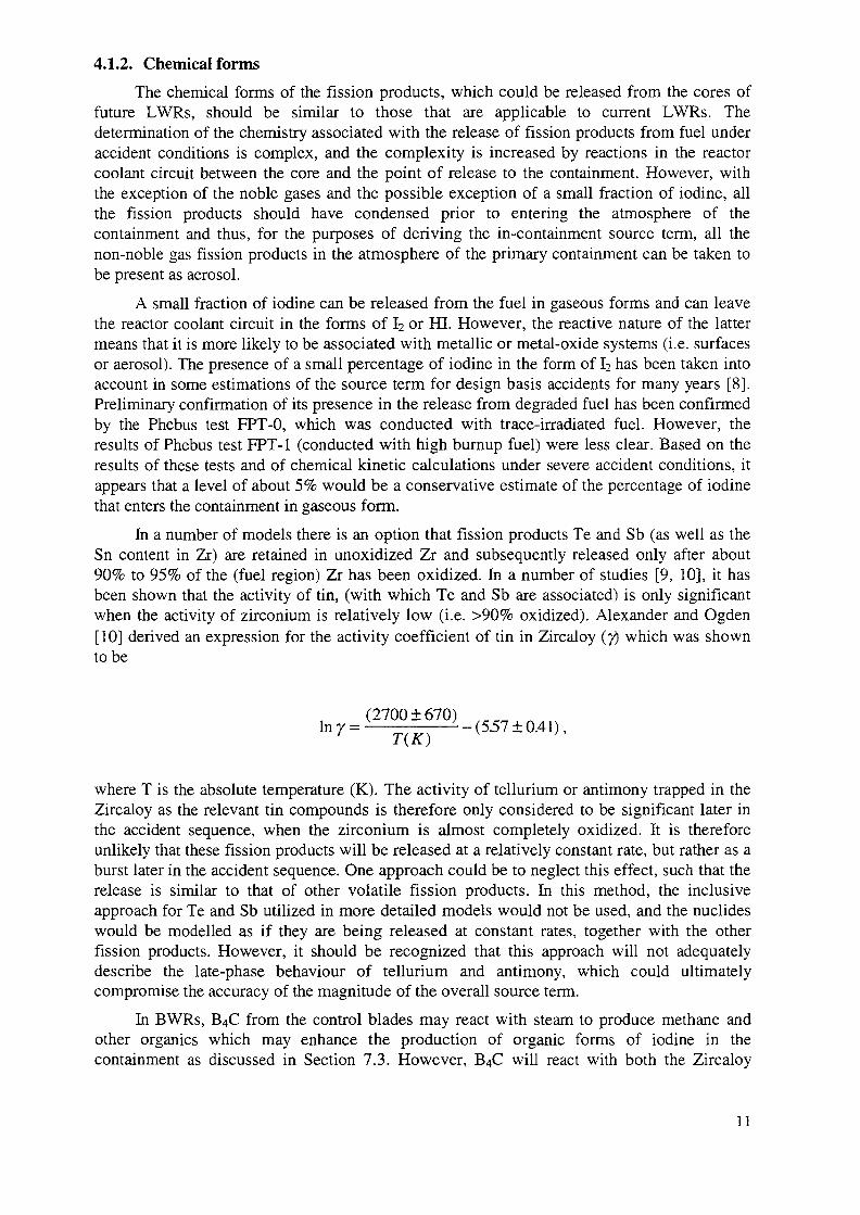
4.1.2. Chemical forms
The chemical forms of the fission products, which could be released from the cores offuture LWRs, should be similar to those that are applicable to current LWRs. Thedetermination of the chemistry associated with the release of fission products from fuel underaccident conditions is complex, and the complexity is increased by reactions in the reactorcoolant circuit between the core and the point of release to the containment. However, withthe exception of the noble gases and the possible exception of a small fraction of iodine, allthe fission products should have condensed prior to entering the atmosphere of thecontainment and thus, for the purposes of deriving the in-containment source term, all thenon-noble gas fission products in the atmosphere of the primary containment can be taken tobe present as aerosol.
A small fraction of iodine can be released from the fuel in gaseous forms and can leavethe reactor coolant circuit in the forms of I2 or HI. However, the reactive nature of the lattermeans that it is more likely to be associated with metallic or metal-oxide systems (i.e. surfacesor aerosol). The presence of a small percentage of iodine in the form of I2 has been taken intoaccount in some estimations of the source term for design basis accidents for many years [8].Preliminary confirmation of its presence in the release from degraded fuel has been confirmedby the Phebus test FPT-0, which was conducted with trace-irradiated fuel. However, theresults of Phebus test FPT-1 (conducted with high burnup fuel) were less clear. Based on theresults of these tests and of chemical kinetic calculations under severe accident conditions, itappears that a level of about 5% would be a conservative estimate of the percentage of iodinethat enters the containment in gaseous form.
In a number of models there is an option that fission products Te and Sb (as well as theSn content in Zr) are retained in unoxidized Zr and subsequently released only after about90% to 95% of the (fuel region) Zr has been oxidized. In a number of studies [9, 10], it hasbeen shown that the activity of tin, (with which Te and Sb are associated) is only significantwhen the activity of zirconium is relatively low (i.e. >90% oxidized). Alexander and Ogden[10] derived an expression for the activity coefficient of tin in Zircaloy (y) which was shownto be
(2700 ±670)lny=K - (5.57 ±0.41),
1 (A )
where T is the absolute temperature (K). The activity of tellurium or antimony trapped in theZircaloy as the relevant tin compounds is therefore only considered to be significant later inthe accident sequence, when the zirconium is almost completely oxidized. It is thereforeunlikely that these fission products will be released at a relatively constant rate, but rather as aburst later in the accident sequence. One approach could be to neglect this effect, such that therelease is similar to that of other volatile fission products. In this method, the inclusiveapproach for Te and Sb utilized in more detailed models would not be used, and the nuclideswould be modelled as if they are being released at constant rates, together with the otherfission products. However, it should be recognized that this approach will not adequatelydescribe the late-phase behaviour of tellurium and antimony, which could ultimatelycompromise the accuracy of the magnitude of the overall source term.
In BWRs, B4C from the control blades may react with steam to produce methane andother organics which may enhance the production of organic forms of iodine in thecontainment as discussed in Section 7.3. However, B4C will react with both the Zircaloy
11
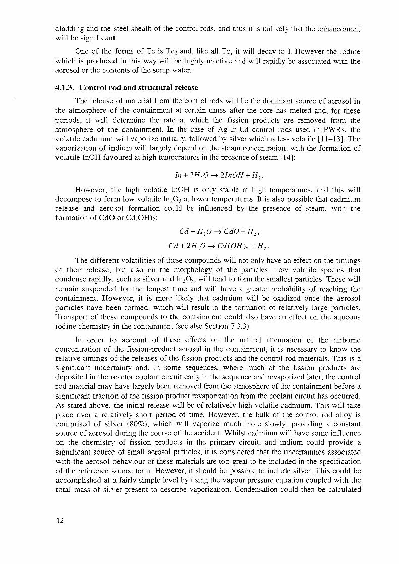
cladding and the steel sheath of the control rods, and thus it is unlikely that the enhancementwill be significant.
One of the forms of Te is Te2 and, like all Te, it will decay to I. However the iodinewhich is produced in this way will be highly reactive and will rapidly be associated with theaerosol or the contents of the sump water.
4.1.3. Control rod and structural release
The release of material from the control rods will be the dominant source of aerosol inthe atmosphere of the containment at certain times after the core has melted and, for theseperiods, it will determine the rate at which the fission products are removed from theatmosphere of the containment. In the case of Ag-In-Cd control rods used in PWRs, thevolatile cadmium will vaporize initially, followed by silver which is less volatile [11-13]. Thevaporization of indium will largely depend on the steam concentration, with the formation ofvolatile InOH favoured at high temperatures in the presence of steam [14]:
In + 2H2O-^ UnOH + H2.
However, the high volatile InOH is only stable at high temperatures, and this willdecompose to form low volatile frbOs at lower temperatures. It is also possible that cadmiumrelease and aerosol formation could be influenced by the presence of steam, with theformation of CdO or Cd(OH)2:
Cd + H2O -> CdO + H2,
Cd + 2H2O -» Cd{OH)2 + H2.
The different volatilities of these compounds will not only have an effect on the timingsof their release, but also on the morphology of the particles. Low volatile species thatcondense rapidly, such as silver and L12O3, will tend to form the smallest particles. These willremain suspended for the longest time and will have a greater probability of reaching thecontainment. However, it is more likely that cadmium will be oxidized once the aerosolparticles have been formed, which will result in the formation of relatively large particles.Transport of these compounds to the containment could also have an effect on the aqueousiodine chemistry in the containment (see also Section 7.3.3).
In order to account of these effects on the natural attenuation of the airborneconcentration of the fission-product aerosol in the containment, it is necessary to know therelative timings of the releases of the fission products and the control rod materials. This is asignificant uncertainty and, in some sequences, where much of the fission products aredeposited in the reactor coolant circuit early in the sequence and revaporized later, the controlrod material may have largely been removed from the atmosphere of the containment before asignificant fraction of the fission product revaporization from the coolant circuit has occurred.As stated above, the initial release will be of relatively high-volatile cadmium. This will takeplace over a relatively short period of time. However, the bulk of the control rod alloy iscomprised of silver (80%), which will vaporize much more slowly, providing a constantsource of aerosol during the course of the accident. Whilst cadmium will have some influenceon the chemistry of fission products in the primary circuit, and indium could provide asignificant source of small aerosol particles, it is considered that the uncertainties associatedwith the aerosol behaviour of these materials are too great to be included in the specificationof the reference source term. However, it should be possible to include silver. This could beaccomplished at a fairly simple level by using the vapour pressure equation coupled with thetotal mass of silver present to describe vaporization. Condensation could then be calculated
12
along the relevant temperature gradient. A good knowledge of silver transport is alsoimportant in order that the iodine behaviour in the containment can be accurately quantified.This is dealt with in more detail in Section 7.3.
Boric acid is present in the primary coolant of a PWR as a soluble moderator. Theconcentration of this material will depend on the point in the fuel cycle [15]. It will be at itshighest with fresh fuel (typically -1200 ppm) and is systematically reduced as the cycleproceeds (typically to a minimum of -50 ppm). In a BWR, the B4C control blades can reactwith steam to form boric acid and methane [16] under accident conditions. Whilst boric acidwill react with metallic surfaces, typically to form borates [17], this will not act as asignificant attenuation mechanism. The influence of boric acid is primarily on the formationof caesium species. Both caesium iodide and caesium hydroxide react with boric acid to formcaesium borate:
CsOH + HBO2 -» CsBO2 + H2O ,
Csl + HBO2 -» CsBO2 + HI.
In the case of the reaction with Csl, volatile hydrogen iodide will be formed, thusinfluencing the behaviour of iodine as well as caesium. Boric acid can react with Csl or CsOHeither in the vapour phase or as a reaction between the fission product vapours and boric acidaerosol, formed by flashing or condensation. The uncertainties associated with the latter aretoo great to be included in the reference source term, but it may be possible to include thevapour-vapour reaction. Vaporization of boric acid is most significant in the presence ofsteam. Studies at ORNL have shown [18, 19] that voltilization occurs up to core melt, afterwhich it ceases due to its affinity for metal oxides. The CsBO? formed by the reactions withcaesium species is far less volatile than either Csl or CsOH, and thus it may deposit earlierthan would be the case for the precursors. However, because of its low volatility, CSBO2 islikely to condense to form small particles that will remain suspended for longer, and thus havea greater chance of reaching the containment. Once the boric acid aerosol reaches thecontainment, it will deposit and ultimately influence the pH of the sump. Volatilization ofiodine from the sump is strongly dependent on pH. Therefore boric acid transport to thecontainment could influence accident management strategies which depend on an alkalinesump. It is also possible that CSBO2 could have an effect on the aqueous iodine chemistry inthe containment. These phenomena are discussed in more detail in Section 7.3.3.
Similarly, because of the large uncertainties in the release models for structural aerosols,we recommend these not be included in the representative source term specification. On theother hand, if particular containment design features are proposed for which a large quantityof structural aerosol would interfere with their proper functioning, there is a need to estimatethe structural aerosol release. This could be done by applying structural release models to thestructural materials in the core assuming that they undergo the same generalized thermaltransient as those which prevailed for the core.
4.1.4. In-vessel melt retention strategies
A feature for some future NPPs may be external cooling of the rector vessel in order toretain the melt within the vessel. If a future plant proposes this strategy, it is recommendedthat no additional in-vessel fission product or aerosol release (over than that calculated for theheat-up and melt period) be included in the source term. The reason for this recommendationis that it is considered that the driving forces for the release of fission products fromunsparged pools and for driving fission products and aerosols out of the primary vessel to theleakage paths will be small, while the melt is in the bottom head, and that little will escapefrom the RCS into the containment.
13
4.1.5. Reflood
Experiments that have included reflooding of the degrading core have shown "spikes" inthe production of hydrogen and the release of fission products. However, the probability of thereflood occurring just at the time when the fission product release has neared its maximumvalue such that any additional release can be considered as an enhancement is extremelysmall. For this reason, it is not considered to be appropriate to include an enhancement of thesource term due to reflooding the core. There may also be accident managementconsiderations resulting from the long term effects of a core immersed in a water pool over along period of time.
4.2. UNCERTAINTIES
Increasing the average burnup to values of greater than 40 000 MW-d/t U may have asignificant effect on the release of fission products and other materials.
The effect of burnup on fission product release is included in the RelVol modeldiscussed and used in the Appendix. However, the database underlying this model is sparseand there are significant uncertainties to be associated with extrapolating the model to (forexample) 60 000 MW-d/t U.
There is a potential for air-ingress to influence the late stages of the source term withrespect to its potential for adding significant Ru, Mo and, perhaps, Pu into the source term.However, the probability of this occurring is considered to be low enough that it need not beaccounted for in the reference source term.
5. EFFECTS OF THE RCS ON FISSION PRODUCT BEHAVIOUR
The effects of the RCS on attenuating the release of fission products and aerosols,changing the timing via revaporization or resuspension, and affecting the chemical forms areundoubtedly important for many severe accident sequences. It is noted, however, that theseeffects are minimized in low pressure sequences in which the fission product residence time inthe RCS is small. It is very likely that future LWRs will employ a strategy of depressurization.Therefore, in the interest of simplifying the regulatory expectations and in developing arepresentative reference source term, it is proposed that no credit be given for the effects ofthe RCS. This greatly simplifies the application of the algorithmic methodology and is notconsidered to introduce any unacceptable distortion into the design basis "representative"source term. However, it should be remembered that exclusion of all primary circuit effectsfrom the definition of the "representative source term" will not necessarily give a maximumvalue. Whilst this may be the case for fission products, other materials such as control rodalloy and boric acid could have an effect on the behaviour of iodine in the containment interms of both mitigating or exacerbating the consequences of an accident.
6. EX-VESSEL SOURCES
Despite the many phenomena that are important for evaluating melt behaviour withinthe containment, the associated fission product source term is generally low compared to thesource term from heating-up and melting of the core within the vessel. This is mainly becauseof the geometrical conditions and reduced temperatures. In order to describe the ex-vesselsource term properly, one has to distinguish between existing plants, where there is no
14
provision against molten core-concrete interaction (MCCI) and those future plants, which willbe designed to avoid penetration of the basemat.
In the case of existing plants, a significant release of fission products and especiallynon-active aerosols is predicted to occur as a result of MCCI after the corium has meltedthrough the reactor pressure vessel (RPV) and fallen into the reactor cavity. The release ismainly driven by gas and steam, which results from the concrete decomposition. Other ex-vessel sources are related to transient phenomena, which occur at about the time that thevessel is breached, or to long-lasting but small effects, namely:
— direct containment heating (DCH) by the corium following high pressure melt ejection,
— fuel-coolant interactions (FCI) in the reactor cavity or spreading area,
— resuspension of fission products from boiling water pools or from surfaces in thecontainment or the RCS due to mechanical or thermal forces,
— the formation of gaseous forms of iodine from involatile forms in the aqueous aerosol,water pools and films (see Section 7).
For future reactor designs, the requirement to mitigate the consequences of severeaccidents has to be taken into account. As a result, measures are expected to be introducedthat might reduce the probability of vessel failure and/or will stabilize the corium in thecontainment to avoid penetration of the basemat. In addition, measures to depressurize thereactor coolant system deliberately will significantly reduce the probability of a high pressuremelt ejection and the early breach of the containment as a result of a missile. However, wherecore retention measures are introduced, there is a need to consider the potential of a releasefrom the molten corium if there is a dry phase and, where water is introduced to cool thecorium, there is the need to consider the release of fission products as a result of theinteraction of the corium with the water.
These phenomena are complex and, in many cases, are plant specific, so that it is notpossible to recommend generic numerical source terms. However, methodologies for derivingthe associated source terms to the containment are given in the following sections. Asmentioned above, the additional ex-vessel source term is generally small.
6.1. MOLTEN CORE-CONCRETE INTERACTIONS (MCCI)
As noted above, MCCI may occur at operating plants but its probability is expected tobe significantly reduced by the design measures that are expected to be incorporated into thedesigns of future plants. A similar type of release may occur if core retention devices involvesome sacrificial materials that also provoke a sparging process.
The reaction between molten corium and concrete without water is sufficiently wellunderstood and can be calculated using codes such as CORCON (NRC) or WECHSL (FZKand IPSN), which have been validated using the SURC (SNL), BETA (FZK) and ACEexperimental programmes. In spite of the Mace experimental programme, which addressedthe late addition of water, uncertainties in the source term to the containment still exist as towhen MCCI stops. Codes to calculate fission-product and aerosol release associated withMCCI, such as VANESA or CHEMSAGE have been validated by the ACE experiments. IfMCCI were to occur, it is expected that all the noble gases, iodine, caesium and tellurium thatremain in the corium will be rapidly released. In addition, the release of moderately volatilefission products such as ruthenium, barium and strontium, and the isotopes of plutonium needto be evaluated, especially if oxidizing conditions occur.
15
The corium spreading and freezing process in a large reactor cavity or spreading area isthe subject of experimental programmes, which have been mainly carried out in France andGermany (FZK: KATS, Siempelkamp: CORESA, CEA: CORINE, VULCANO, JRC: FARO[20, 21]) and these experiments will provide the necessary data to validate the codesCORFLOW (Siemens), MELTSPREAD (EPRI) and CROCO (IPSN). However, theconsensus of expert opinion is that if the corium can spread over a large enough area and if itis quenched with water, there will be no significant enhancement of the source term tocontainment as a result of MCCI.
6.2. RELEASE FROM MOLTEN POOLS
Fission product release from molten pools is generally taken to be an ex-vesselphenomena. However, it is also relevant to in-vessel processes where fuel liquefaction occursprior to vessel failure. The general assumption with respect to molten pool behaviour is that,where a core retention device retains the corium in the form of a molten pool and no spargingoccurs, there will be no significant addition to the source term to the containment. In the caseof the noble gases, iodine and caesium, around 50% of the inventory is expected to be releasedduring the in-vessel phase, as outlined in Section 4. For the other nuclides, the lowequilibrium activity coefficients and the potential for the formation of a crust lead to thejudgement that the release will not be significant. A programme comprising experiments toexamine the release of fission products from metallic and oxide melts, associated codedevelopment and testing, and plant calculations has been conducted by AEA Technology,NES/Ruhr University of Bochum, IPSN, Siemens/KWU and Leningrad Special KombatInstitute "Radon" (LSK, St. Petersburg) as part of the Commission of the EuropeanCommunities 4th Framework Programme. The experiments have addressed such issues assparging, and crust formation, whilst the code testing and development has been concernedwith development of the RELOS/CHEMSAGE code package. Plant calculations have beenmainly concerned with issues associated with the EPR. Preliminary results from theexperimental programme [22, 23] have shown that there was significant release of fissionproducts of intermediate volatility (Ba, Sr, etc.), even in the absence of sparging. Rutheniumwill only be released in oxidizing atmospheres due to the formation of volatile RUO3. Theexperimental results for this programme need to be assessed further with respect to thebehaviour of ruthenium and that of the lanthanides and actinides.
6.3. FUEL-COOLANT INTERACTION (FCI) AND DIRECT CONTAINMENTHEATING (DCH)
In the context of the source term to the containment, the phenomena of FCI and DCHhave the potential to fragment the molten fuel thermally or mechanically, provoke chemicalreactions and change the chemical nature of the fission products into more volatile forms. Themost important chemical reactions are those that lead to the formation of ruthenium oxideswhich are both volatile and radiologically significant.
The subject of energetic fuel-coolant interactions or steam explosions has beenextensively considered from the point of view of creating missiles which would threaten theintegrity of the containment. The work prior to 1985 was considered by the first SteamExplosion Review Group in the USA, which concluded that the probability of such an event islow enough to be considered negligible. More recent work presented at the CSNI SpecialistsMeeting in Santa Barbara in 1993 supported the above conclusion. For several years,considerable research, in the form of the QUEOS, PREMDC and BERDA experimentalprogrammes and the development of the FVA-KA code, has been under way at FZK to
16
demonstrate that a steam explosion with the consequence of a containment failure ispractically excluded. Nevertheless, 'minor' steam explosions, which are limited to a smallfraction of the core, may have an influence on the source term. Because of the difficulty ofcalculating the corresponding fission product release, it is recommended that the release of alllow and medium volatile species, including Ru, which are contained in this fraction of thecore, is assumed. As this fraction of the core is small, the reference source term is stillconsidered to be adequately conservative to have included this contribution. For both presentreactor designs, as a result of accident management, and future designs, as a result of designmeasures, DCH will be practically avoided or limited by depressurizing the reactor coolantcircuit sufficiently early, in order to avoid vessel failure above a threshold pressure level.Experiments will be performed by FZK to define this threshold.
6.4. ADDITIONAL EX-VESSEL PHENOMENA
In addition to the production of gaseous forms of iodine, which is addressed in Section 7,the other phenomena which have the potential to affect the source term are:
— the revolatilization of fission products which are deposited on the surfaces of the reactorcoolant system and the containment,
— the resuspension of radionuclides from boiling water pools,
— the effects of hydrogen burns and the use of recombiners,
— the use of spray with chemicals added to the sump or spray water.
It is the consensus of expert opinion that none of these phenomena are really importantin deriving the cumulative source term from the containment for the sequence that is relevantto the present report, where the integrity of the containment is maintained and the source termis to be used for design purposes.
Revolatilization may affect the timing of the release to the containment, but neglectingretention in the reactor coolant circuit, as discussed in Section 4, will lead to a reasonablyrobust source term. Revolatilization will, however, be an important phenomenon in riskanalyses which consider sequences where the containment fails or is vented.
The resuspension phenomenon in pipes has been studied in various national andinternational experimental programmes and continues to be the subject of the STORMprogramme, but again, neglecting retention in the primary circuit leads to a reasonably robustsource term and avoids the uncertainties associated with predicting the thermal-hydraulicbehaviour of the reactor coolant circuit.
The judgement that resuspension from the boiling sump will not significantly affect thesource term is expected to be confirmed by the ongoing experimental programme at FZK(KAREX) and related theoretical work.
The following effects are associated with hydrogen mitigation:
— hydrogen burns: mechanical resuspension, effect on iodine chemistry (short, but hightemperature peak);
— recombiners: superheated atmosphere and thus less condensation of steam on aerosols,smaller aerosol size distribution and lower removal rate, effect on iodine chemistry (seeSection 7).
The magnitude of these effects is negligible in the context of the conservative procedurefor calculating the removal of airborne aerosols, as proposed in Section 7.
17
7 IN-CONTAINMENT BEHAVIOUR OF FISSION PRODUCTS
7.1. INTRODUCTION
The release of radioactivity from the containment depends on the magnitude andchemical and physical form of the radioactivity that is airborne in the containment as afunction of time. Thus, once the source term to the containment is established, it is thesubsequent behaviour of the released material within the containment that determines the in-containment source term.
The regulatory requirements associated with the use of design-basis source terms andthe subsequent behaviour of the fission products in the containment sometimes take the formof an acceptable dose criteria at the site boundary given an additional design basisspecification that establishes a pressure source in the containment to be coupled to a designleak rate. The pressure "source term" specification in some countries is to use the maximumpressure resulting from the containment response to a set of design basis accidents. Thispressure is specified to be held constant for a relatively long time (e.g. 24 hours). The pressuresource also includes a contribution from the burning of some specified fraction (of the totalpossible) of the hydrogen that is expected to be generated by severe accidents. In developingthe containment response, credit has been allowed for engineered safety features such as theuse of sprays for containment cooling and the removal of gaseous iodine, the use ofsuppression pools if they are not saturated, and the use of coolers.
It was never intended that design-basis source terms be used with any particular accidentsequence to determine the dose at the site boundary. Instead, the intent was that thecombination of the fission product source term, the pressure source term, and the containmentdesign leakage rate results in an acceptable containment design with respect to overall riskresulting from all accident sequences. Although it would seem consistent to develop the in-containment behaviour by using an actual depressurized (large break LOCA) sequence, thisshould not be done because the "representative" source term presented here is a surrogate forthe spectrum of credible severe accident sequence source terms. It is not appropriate to try toidentify it with any one sequence.
It is clear that the evaluation of the thermal-hydraulic behaviour of the containment withrespect to any particular accident sequence is only appropriate for general guidance and is notto be used to evaluate the in-containment behaviour of the reference source term aerosols. Thequestion then is how to deal with containment thermal-hydraulic effects in evaluating the in-containment behaviour of the design-basis representative source term. Clearly, since there isno technically defendable basis for coupling the source term to any specific timing associatedwith thermal-hydraulic phenomena and to parameters such as diffusiophoresis,thermophoresis, and relative humidity, then it is inappropriate to take these into account.
The aerosol behaviour phenomena, in which high confidence can always be placed onthe expectation that the effect will always be present for all accident sequences at all times, areagglomeration (gravitational and Brownian), gravitational settling and diffusional plateout. Inaddition, in order to encourage the innovative use of engineered safety features (e.g.containment sprays and suppression pools) for source term mitigation, credit should beallowed for these only in proportion to the confidence level that can be placed on theiravailability during severe accidents. Thus, it is proposed that only the above phenomena andreliable ESF systems be used in evaluating the in-containment behaviour of fission productaerosols.
The reference pressure "source" to be used along with the in-containment aerosolbehaviour is a separate issue. An option would be to stay with the above-mentioned approach
18
of design basis accidents and utilize the maximum pressure arbitrarily held for some specifiedperiod of time. While this appears to be an appropriate regulatory approach, there is still anissue of what credit, if any, should be allowed for the use of ESFs in reducing the design basispressure. In making any decision on this issue, appropriate consideration should be given as towhether or not an acceptable level of defence in depth is achieved in view of the reliabilitiesof the proposed ESFs.
Aerosol agglomeration, gravitational settling and the effect of ESF actions on thetransient aerosol concentrations in the containment are generally included within detailedmechanistic aerosol codes such as CONTAIN, ECART, FIPLOC, FUMO, GOTHIC,JERICHO, MAAP, and MELCOR. One possible acceptable approach to account for the in-containment aerosol behaviour would be to use such codes to determine the transient aerosolbehaviour but, in deriving the reference in-containment source term, it will be necessary to"turn off all associated thermal hydraulics along with the models for diffusiophoresis,thermophoresis, condensation and hygroscopic effects.
In keeping with the spirit of this report, simple algorithms are proposed to capture theessence of these mechanistic models for the effects of:
— Brownian and gravitational agglomeration,— gravitational settling,— spray removal,— decontamination by water pools.
7.2. IN-CONTAINMENT AEROSOL BEHAVIOUR ALGORITHMS
7.2.1. Agglomeration and gravitational settling
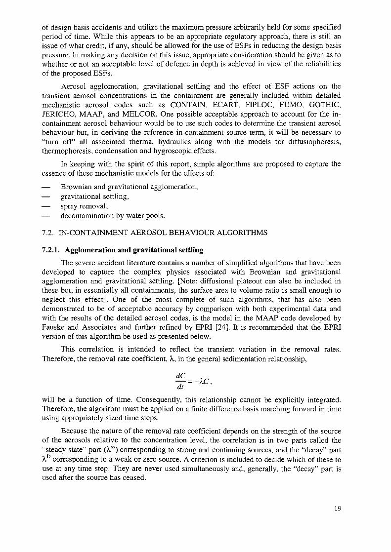
The severe accident literature contains a number of simplified algorithms that have beendeveloped to capture the complex physics associated with Brownian and gravitationalagglomeration and gravitational settling. [Note: diffusional plateout can also be included inthese but, in essentially all containments, the surface area to volume ratio is small enough toneglect this effect]. One of the most complete of such algorithms, that has also beendemonstrated to be of acceptable accuracy by comparison with both experimental data andwith the results of the detailed aerosol codes, is the model in the MAAP code developed byFauske and Associates and further refined by EPRI [24]. It is recommended that the EPRIversion of this algorithm be used as presented below.
This correlation is intended to reflect the transient variation in the removal rates.Therefore, the removal rate coefficient, X, in the general sedimentation relationship,
dC
will be a function of time. Consequently, this relationship cannot be explicitly integrated.Therefore, the algorithm must be applied on a finite difference basis marching forward in timeusing appropriately sized time steps.
Because the nature of the removal rate coefficient depends on the strength of the sourceof the aerosols relative to the concentration level, the correlation is in two parts called the"steady state" part (kss) corresponding to strong and continuing sources, and the "decay" partA° corresponding to a weak or zero source. A criterion is included to decide which of these touse at any time step. They are never used simultaneously and, generally, the "decay" part isused after the source has ceased.
19
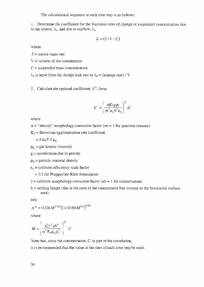
The calculational sequence at each time step is as follows:
1. Determine the coefficient for the fractional rates of change of suspended concentration dueto the source, Xs, and due to outflow, \0
L = {S/V/C)
where
S = source mass rate
V = volume of the containment
C = suspended mass concentration
A.o is input from the design leak rate as Xo = (leakage rate) / V
2. Calculate the optimal coefficient, XSi, from
where
a = "density" morphology correction factor (set = 1 for practical reasons)
Ko = Brownian agglomeration rate coefficient
= 4 kBT/3 \L,
[la = gas kinetic viscosity
g = acceleration due to gravity
pp = particle material density
80 = collision efficiency scale factor
= 1/3 for Pruppacher-Klett formulation
y = collision morphology correction factor (set = 1 for conservatism)
h = settling height (this is the ratio of the containment free volume to the horizontal surfacearea),
and
where
M = •C
Note that, since the concentration, C, is part of the correlation,
it is recommended that the value at the start of each time step be used.
20

3. Decide whether or not to use the "steady-state" or the "decay" correlation from the criteriabelow.
If 35 / A"f< C use" steady - state"
|> C use" decay"
4. If decay correlation is selected from the criteria, calculate the coefficient for the "decay"option from
XD=XSSAD/ASS
where
AD = 0. O.473M0J54)a786
5. Either total fractional rate of increase of suspended mass for the time step using theappropriate coefficient (1) or (2) below as indicated by the criterion in step 3:
(1) "Steady state": A = ( rp r V +
where
As£o/A =
Rls = A0/A
or
j ^ S
3 ^1 +
1 + R? 13
4.5 0.222
D/ A = 1 + RL
Note that, if the leakage rate is zero or very small, then the above correlation optionsreduce to
(1) "steady state": X - -A55 + A and
(2) "decay": A = -AD + As
It should be noted that this algorithm implicitly assumes the source aerosol size to besmall and log-normally distributed and, therefore, does not require an input specification foreither the mean size or the variance.
21

7.2.2. Spray removal of aerosols
The basic equation used for spray removal of aerosols is,
dmf
^ , (1)
in which mf is the mass fraction [M(t)/M0] of aerosol remaining airborne in the containmentas a function of time, t.
Generally, the removal rate coefficient, e, has been found to be a function of the sprayflow rate (on a per nozzle area coverage basis), Q (cm7crrr s) and the spray droplet fallheight, H(cm) as well as the spray droplet diameter, the aerosol size, and the massconcentration of aerosols airborne, M(t).
Powers [25], however, noted that the distributed range of droplet sizes from standardnozzles currently in use is sufficiently narrow that it can be treated as an uncertainty parameterrather than as an independent variable. Similarly, from the results of severe accidentcalculations that used the Source Term Code Package (STCP), he noted that the distributedaerosol size as released into containment from the RCS or from dry MCCI can be wellrepresented by a log-normal distribution with the range in the mean size of 1.5 to 5.5 1m(assumed uniformly distributed in his uncertainty analysis) and a geometric standard deviationrange of 1.6 to 3.7 (also assumed uniformly distributed) and can, therefore, also be treated asan uncertainty parameter.
Consequently, these two parameters, along with other important influencing parameters,were exercised in an uncertainty assessment [Monte Carlo sampling] from appropriatelyassigned distributions by Powers using a detailed mechanistic model for spray removal. Thismechanistic model purposely did not include condensation (or diffusiophoresis) andthermophoresis effects.
Powers correlated the results for the calculated distribution of the rate coefficient for the10%, the 90%, and median values in terms of the important independent variables, Q and H,and the important dependent variable, mf. These correlations were developed in two parts:
(a) A,(nif) = 0.9 —» presented as a function of Q and H, and
(b) X(mf) / A.(mf = 0.9) —> presented as a function of Q and mf,
to give an overall X(rrif) as a function of Q, H, and mf.
The basic relationship, then, becomes :
dmf
—L = -UQ,H,mf)mf (2)at
Power's correlation for the median result of the uncertainty analysis (which is recommendedhere) is
In Mmf = 0.9) = 6.83707 + 1.0074 In Q - (4,1731 xl0~3)Q2H - (1.2478)Q
- (2.4045 x 10"5)H + (9.006 x 10~8)QH2
where
X has units of h"1,Q is in cnrVcm2 s, andH is in cm.
This is to be combined with
0.5843X(mf)A,(nu=0.9) = (0.1815 - 0.01183 log,0Q)-[l - (mf/O^f384'] + (mf/0.9)
Since A, is a function of rrif, the procedure recommended here for the simplifiedalgorithm is as follows:
(1) Input into the correlations the known values for Q and H to get X as a function of mfalone.
(2) Substitute the result of (1) into Equation (2) and numerically solve for mf as a functionof time.
If there are fractional volumes of the containment that are unsprayed,
[a = V (unsprayed)/V(sprayed)], then the effective X would be
7.2.3. Pool scrubbing decontamination factors
Similar to the above treatment to develop a simplified correlation for spray removal ofaerosols, Powers [26] also exercised a detailed mechanistic model in an uncertainty mannerover the ranges of important parameters to develop a simplified correlation fordecontamination by suppression pools.
Along the lines of his spray analysis, Powers treated the assumed log-normal aerosolsize distribution characteristic of the in-vessel release as being an uncertainty parameter (both|i and a). He also treated the carrier flow (steam and hydrogen) as an uncertainty parameteralong with the uncertainties in the phenomenological relationships. This approach left only thedepth of submergence of the quenchers as being the important independent variable. Thecorrelation developed by Powers applies to both "T" and "X" quencher designs.
The parameter of interest, of course, is the decontamination factor, DF, defined as theratio of the total mass of aerosol entering the pool to the total mass escaping after passagethrough the quencher submergence depth, H.
The median correlation (considered here to be the best estimate value) developed byPowers is simply:
log10DF = 1.791 + (2.477 x lO~3)H(cm)
A measure of the spread about the median can also be obtained with Power'scorrelations for the 10 and the 90 percentile values which can be viewed as lower and upperbounds on the DF:
and :(90%)log10£>F = 3.964 + (6.028 x 10"3 )H(cm)
23
Note: in evaluating the reduction of the reference source term into containment as aresult of its passage through a suppression pool, it is important to make an assessment of thebypass and exclude that portion from the removal by the suppression pool. It should also benoted that the description of Powers does not apply to the churn-turbulent flow regime, but isonly applicable to bubbly flow conditions. It is possible to envisage scenarios in which churn-turbulent flow will be important, and this effect is not currently modelled by pool-scrubbingcodes such as BUSCA and SPARC [27, 28].
7.2.4. Containment coolers
In some designs, fan coolers are provided to reduce the containment temperaturefollowing a severe accident. Fan coolers will also remove aerosols from the flow stream butthe removal process is diffusiophoresis via steam condensation. As discussed above,diffusiophoresis processes are specific to individual fault sequences and have therefore notbeen included in the derivation of the representative in-containment source term.
7.2.5. Major uncertainties and R&D requirements in aerosol behaviour
The basic phenomena associated with aerosol physics including particle agglomerationand gravitational settling are well understood. There are, however, uncertainties associatedwith the specification of the initial aerosol size distribution and with the so-called shapefactors. The uncertainty in size can be compensated for by specifying a small size asrecommended above. The uncertainties associated with shape factors can partially be dealtwith by conservatively setting the agglomeration shape factor to 1. Setting the dynamic shapefactor (settling velocity effect) to a value of 1 will not be conservative. However, in view ofthe fact that most severe accident sequences occur at high humidity and that the resultingaerosols are hygroscopic, using a value of 1 for this shape factor is probably appropriate.
7.3. IODINE BEHAVIOUR INCLUDING pH CONTROL
7.3.1. Introduction
For PWR designs where the pH of the sump water is controlled at 8 or greater for theduration of the accident and where the materials in the containment and those released fromthe reactor coolant circuit are typical of current designs, the simplification of assuming that allthe iodine remains in the form of Csl will be appropriate, providing that it can bedemonstrated that the formation of acids does not significantly reduce the pH of the aqueousaerosol (airborne). It should also be noted that boric acid from the primary coolant in a PWRor the B4C control blades in a BWR will also have the effect of reducing the pH of the sumpin an accident (see also Section 4.1.3).
However, if the pH is not controlled, there is the potential for it to fall significantlybelow 8 for the reasons outlined in Section 7.3.3 below. In this case, there will be aconsiderable increase in the production of gaseous iodine, such that the total release from thecontainment is measured by a factor of 5 compared to that which is predicted if all the iodineis present as Csl. Currently data are not sufficient to predict with confidence that moleculariodine will be trapped by materials such as silver from the control rods (if present, see Section4.1.3), and thus a full account of iodine chemistry must be made when evaluating thispotential contribution to the source term. This evaluation must include the production ofvolatile forms by radiolysis in the aqueous aerosol and in the sump or suppression pool wateras well as the subsequent production of organic iodine.
24
7.3.2. Phenomena
The dominant form of iodine released from the core in most accident sequences isexpected to be F, which will be converted into Csl vapour within the RCS. In the RCS or atleast on entering the containment, the Csl vapour will condense to form an aerosol but,because of its hygroscopic nature, Csl will either dissolve in airborne water droplets or, in thesteam-rich atmosphere, it will form nuclei for condensation droplets and form Cs+ and F.Thus, the majority of the iodine will initially be in the form of F in the aqueous phase of theprimary containment atmosphere.
The aqueous aerosol will be transported to the sump or to other surfaces within thecontainment by the natural processes described in the previous section, or by the containmentsprays. However, F in the aqueous aerosol or the sump, can be converted to the volatile formsI2 or HOI by radiolysis, due to the high radiation fields in the containment. The same willoccur in the water of the suppression pool in a BWR. These volatile forms can be transferredto the gas phase by mass transfer and, since they will be removed from the containmentatmosphere at a slower rate than the aerosol, they have the potential to significantly enhancethe quantity of iodine that is airborne in the containment atmosphere and thus the source termto the environment.
In turn, gas phase iodine can undergo mass transfer to the aqueous phases of the aerosol,the sump or suppression pool or the droplets of the containment spray system. Anotherpotentially important mechanism for removing iodine from the containment atmosphere isdiffusiophoresis, whereby both gaseous iodine and the aerosol are transported to surfaceswhere condensation is occurring and iodine in the aqueous phase can drain to the sump. Inaddition, I2 and HOI can further oxidise to IO3, which is involatile, or it can be formed by Iireacting with ozone in the atmosphere of the containment, although this behaviour can beconsidered to be atypical.
In addition to radiolysis, there are several other chemical reactions which have thepotential to affect the behaviour of iodine in the containment significantly. In particular,volatile organic iodine compounds can be formed by reactions of iodine in both the gaseousand aqueous phases. The hydrocarbons needed for such reactions may be present in thecontainment before the onset of the accident, or they may be produced during the course of theaccident. Potential sources of hydrocarbons are, for example, paints, coatings, oils, lubricants,and cable insulation material in the containment and boron carbide in the core (see Section4.1.3). The release of hydrocarbons may be due to radiolysis, heating, or chemical reactions.Organic iodine is not as reactive as molecular iodine and it is not readily removed by spraydroplets. Thus, it has the potential to remain airborne in the containment atmosphere.
Other potentially important reactions include the reactions of volatile iodine with silverin the aqueous phase and with ozone in the gaseous phase. In some operating PWRs, silver ispresent in the control rods and a much larger mass of silver is released to the primarycontainment during a core melt than of iodine (see Section 4.1.3). The presence of silver leadsto the potential for the formation of Agl, which would reduce the amount of volatile iodinethat is present in the containment atmosphere. However, this potential mechanism for trappingiodine will not occur in those new generation reactors where silver is not used as a rodmaterial. In the absence of a radiation field, molecular iodine has been measured to react withozone in the air to produce IO3", which will condense on the aerosol. This may also be animportant mechanism in wet atmospheres where the radiation levels are high.
A major factor which affects the rate at which volatile iodine is produced in the aqueousform is the pH of the water as discussed in Section 7.3.2. A second important factor is the rateat which mass transfer occurs between the aqueous and gas phases. In the case of a PWR
25
sump, the water can be boiling when it comes into contact with corium released from thevessel. Currently there are few experimental data for the mass transfer between the sumpwater and the gas phase for a boiling sump.
An upper bound value is obtained by assuming instantaneous equilibrium between I2 inthe steam and I2 in the sump, which is currently considered to be the best estimate approach.An effective rate constant for pool boiling is given by:
kevap=B/(Viiq . pc)
where:
B is the sump boiling rate (m3.s"'),
Vijq is the sump volume (m3) and
pc is the L volume partition coefficient.
The overall rate constant is, therefore:
k,otai = 1/Vuq . (B/pc + Vmt. Aig)
where:
Vmt is the mass transfer rate (m.s"1) and
A]g is the liquid/gas interfacial area (m2).
The overall rate constant will be dominated by the sump boiling effect. The boiling ofthe sump is expected to result in the above behaviour for the volatile reactants, I2, HOI, H2 andO2.
In the non-equilibrium case, the reverse partitioning rate constant is that which wouldapply to a non-boiling sump with a forward (gas to liquid) mass transfer coefficient in theorder of 3.1O'6 m s"1. The actual behaviour is expected to lie between these extremes.
In order to evaluate the in-containment source term, all the above processes need to beconsidered and, as a result, computer models have been developed to predict iodinebehaviour. These are briefly described in Section 7.3.4. However, the relative importance ofthese processes critically depends on the pH of the aqueous phase, as discussed immediatelybelow.
7.3.3. pH control
Controlling the pH is a major factor which affects the distribution between volatile andnon-volatile iodine species in the containment. If, during the whole duration of the accidentsequence, the pH of the aqueous phase is kept alkaline, at a value greater than 8, a very limitedfraction of iodine will be converted into volatile species (elemental iodine and organic iodide)in the sump or suppression pool water. If, on the contrary, during the course of the accidentthe pH drops into the neutral or acidic range, the distribution of iodine species can beconsiderably different, with the volatile forms becoming dominant inside the containment.
In some NPP designs, pH control is practised either by storing chemicals in thecontainment at a place where they are inherently flooded and dissolve in the sump water or bypumping them into the containment during an accident using the containment spray system.The disadvantage of the former is that in some plant designs, water in the containment mayexist in the form of separate pools, and in order to inhibit the production of elemental iodine,
26

the engineering design should ensure that the pH of each pool is adequately controlled. Thedisadvantages of the latter are that
— highly alkaline water is introduced into the containment if the spray system is activatedinadvertently and
— pH control depends on the successful operation of the spray system.
If the design does not include an engineered system for controlling the pH, the pH willneed to be calculated in order to evaluate the iodine source term. The assessment of the pH ofthe containment water pools must take into account the following materials and phenomena:
— boric acid and boron oxides (acidic);
— caesium hydroxide and caesium borates (basic);
— other basic compounds which may be formed such as metal oxides and hydroxides (e.g.Cd(OH)2);
— hydrogen iodide (acidic);
— pH additives such as lithium hydroxide, sodium hydroxide and tri-sodium phosphate (allbasic);
— absorption of atmospheric CO2 and CO2 generated by MCCI by water to form carbonicacid;
— irradiation of water and air to form nitric acid;
— core-concrete interactions producing basic oxides (K2O, Na2O and CaO);
— pyrolysis and radiolysis of organo-chlorine and -sulphur materials producinghydrochloric and sulphuric acids;
— acids formed due to dissolution of paints.
Some sources of chemicals are difficult to quantify, for example radiolysis and pyrolysisproducts. Since exact data on release rates may not be available, the pH must be calculatedusing estimates for the amounts of acidic and basic materials that are conservative. Thisapplies to the accident sequences both with and without the pH control systems.
7.3.4. Computer codes
In order to predict the behaviour of iodine in the containment, several computer codeshave been developed. Five codes which model the behaviour of iodine are INSPECT [29, 30],IODE [31, 32], IMPAIR [33, 34], the LIRIC database [35] and TRENDS [36]. All of theseconsider many chemical processes that occur in the course of the accident. The modellingconcepts and underlying databases of the mechanistic INSPECT and empirical IODE andIMPAIR codes are discussed in detail in Ref. [37]. This comparison identifies severalimportant differences. In particular, INSPECT is the only code which models radiolysis in theaqueous aerosol which is potentially the greatest source of gaseous iodine in the containmentatmosphere. On the other hand, it does not model the production of organic iodine, which ispotentially another important source of gaseous iodine and which is modelled empirically inthe other codes. However, a general requirement is that a good overall model is required forthis process. As illustrated in Ref. [38], there are other important differences in terms of themodelling of mass transfer from the boiling sump water, condensation, the transfer ofcondensed water from the containment surfaces to the sump and the reaction of moleculariodine with ozone to produce iodinate. Thus, for a complete description of iodine behaviour inthe containment, more than one of the existing codes is required. However, from analyses
27
such as those described in Ref. [38], some general conclusions can be drawn which have beensummarised in Section 7.1.1 above.
7.3.5. Uncertainties and R&D requirements
The major uncertainties which affect the production of the in-containment iodine sourceterm are as follows:
(1) Although there is considerable evidence to support the view that the major release ofiodine into the containment will be in the form of Csl, the completed Phebus FP testsshow that a significant proportion of the iodine release was in gaseous form. In addition,there is an uncertainty associated with the chemical forms of the constituents of therelease from the reactor coolant circuit which affects the quantity of chemicals that isrequired to achieve a pH in excess of 8.
(2) The effect of acid formation and other processes on the pH of the aerosol and of thesump water in sequences where the pH control is not effective should be determined forreleases into the reactor building, taking into account the nature of the non-aqueousaerosol.
(3) For reactor designs where low pH sequences have a high frequency, validated modelsare required for reverse partitioning and the return flow of iodine to the boiling sump(either by condensation or "wash-out") and the pH dependency of iodine behaviour atthese low pH values.
(4) The extent to which the iodine transferred to water pools will dissolve should bedetermined for releases to suppression pools. If significant pool scrubbing can beestablished, the following code developments should be addressed:
(a) the effect of the presence of silver on slowing the radiolytic oxidation of iodine;(b) the effect of the formation of nitric acid, and competing chemical reactions, on the
solubility of the silver aerosol. This could greatly increase the formation rate ofAgl.
(5) Data are required in severe accident conditions to determine the importance of iodinateformation as a result of iodine reactions with ozone. The data need to address both theformation of ozone and its reactions with iodine.
(6) In plants which use boron carbide as an absorber material, when the core is heating up,boron carbide can form an eutectic melt with the steel cladding surrounding it. Aftercladding failure, direct reactions between boron carbide and the steam present in thesurrounding atmosphere have the potential to generate methane. This phenomenoncould lead to the production of organic iodine. Therefore, there is requirement todetermine whether methane will be formed by this process and if it will react withiodine.
(7) Another area of uncertainty is related to the hydrogen production inside the containmentduring a severe accident. Experiments have shown that hydrogen burns, due to theactuation of igniters, can convert a significant amount of iodine into volatile species.Further data are required to remove the existing uncertainties including the effects ofblank recombiners.
(8) The reaction schemes between iodine and the containment surfaces, both in the aqueousand the gaseous phase, need to be better understood in order to determine which kindsof surface have the potential to irreversibly retain volatile iodine.
(9) More information is required on the reactions of iodine in the gas phase.
28
8. SPECIFICS OF NEW GENERATION DESIGNS
8.1. GENERAL CONCEPTS OF NEW GENERATION PLANTS
It is expected that the designs of new generation nuclear power plants will build on thedesign and operating experience of existing plants. It is anticipated that some of thesedevelopments will address severe accidents by design, as outlined in the EPRI UtilityRequirements Document (EPRI URD) and in the European Utility Requirements Document(EUR).
As economics, in general, and investment protection, in particular, are major concernsfor the utilities, in addition to safety, their major priorities include:
— improving the system reliability;
— making the plant more forgiving in terms of the effect of incidents and accidents on botheconomic penalties and risk;
— decreasing the major contributors to the generation cost, i.e.
• the investment cost, through simplification of the design,• the operational and maintenance costs, and• the fuel cycle cost.
The requirement to control severe accidents mainly affects:
— the reactor coolant system (melt retention, depressurization, passive heat removal);
— containment devices (for melt retention and hydrogen mitigation);
— containment design (heat removal, leak rate, fission product pathways).
In pursuing these objectives, some potential design changes will affect the source term,and an integral part of the design process is to ensure that developments do not lead to anunacceptable source term.
For the sake of clarity, a distinction is hereby made between two aspects of the design ofnew generation nuclear power plants, namely:
— aspects which are not expected to change during the life of the plant, or whosemodification would result in heavy costs for the utility (e.g. the RCS water inventoryand means for melt retention);
— those modifications which can be introduced during the life of the plant, depending onthe implications on cost or regulatory acceptability, e.g. new fuel designs: increasing theburnup, new control rod materials, burnable poisons, new cladding material, and meansfor hydrogen control such as: recombiners, igniters and post-inertization devices.
The former will be illustrated in Section 8.2 which discusses some examples of specificdesign features of the AP 600, the EPR, a simplified BWR and the WWER-640 designs,which have the potential to influence the source term. Some aspects of fuel development willbe addressed in Section 8.3.
29
8.2. SPECIFIC CHARACTERISTICS OF NEW GENERATION PLANTS (AP600, EPR,SIMPLIFIED BWR, AND WWER-640) WHICH AFFECT THE SOURCE TERM
8.2.1. Specific characteristics of the AP600
The AP600 design incorporates some specific design features which will affect thesource term, including the following:
— The thermal output of the core is less than for most current plants. This is not expectedto result in major differences with respect to evaluating the source term. However, thelower core inventory could result in less constraints on the design of some systems dueto increased grace periods.
— Safety injection system design:
• High and medium pressure components of the system. These are essentially the coremake-up tanks (CMTs) and the accumulators. These are storage tanks of boratedwater whose function is to provide water to the RCS in the case of a depletion of theinventory in the short term after the accident. As they cannot prevent a core melt andsince system actuation is independent of those that are used for long term cooling,they can reasonably be considered to be available during fission product release.Their effect is to provide additional water to the RCS and, thus, to delay coredegradation. Therefore, they influence the timing of events but they are not expectedto have a major effect on the source term.
• Low pressure part of the system. The IRWST is the permanent source of water to theRCS for the long term removal of decay heat. It therefore must be unavailable for acore melt to occur.
— Flooding the cavity to provide ex-vessel cooling is possible through dedicated lines. Ifthis design provision is shown to prevent penetration of the vessel by the molten core inmost or all low pressure sequences reliably, the contribution of MCCI to the source termneed not be considered.
— Automatic depressurization system: this engineered safety system is provided for rapidRCS depressurization after a LOCA. Its influence on the source terms defined in thisdocument, is accommodated in the specification of the type of LOCA which should beconsidered to evaluate the source term. However, the design of the system is such that itprovides confidence that high pressure sequences need not be considered in theproposed approach.
— Passive containment cooling system: water supplied from an external storage tank forthe first 72 hours, or air in the longer term if the tank is not replenished, provides fordecay heat removal from the containment. This heat sink promotes turbulence inside thecontainment atmosphere and facilitates aerosol growth and gravitational settling.
— pH is maintained higher than 8 in containment water pools by a pH control system. Thislimits the formation of gaseous iodine, either elemental or organic.
— Igniters and passive autocatalytic recombiners limit H2 buildup inside the containmentand can influence aerosol chemistry, in particular, iodine species.
30
8.2.2. Specific characteristics of the EPR
The EPR is being designed for compliance with regulatory recommendations, asspecified in the GPR-RSK document, and with EUR. The most important features orrequirements which have the potential for influencing the source term are:
High thermal output (about 4900 MW) together with the target of a high burnup(envisaged as 60 000 MW-d/t U) and a large flexibility in the use of MOX fuel (Thedesign target is 50% MOX fuel). This obviously influences the decay heat level, andthus the timing of events, the fission product inventory (long-lived fission products areproportional to the burnup) and the release fraction. The influence of MOX fuel on thecomposition of the fission products is of minor importance.
Reliable depressurization system (normal bleed system for design-base accidents and adedicated bleed system, with the same capacity, for severe accident conditions) provideda high confidence that low pressure sequences will be the only relevant ones forevaluating the source term.
Ex-vessel melt retention to avoid basemat ablation. This is done in three steps involvingthe reactor pit and a dedicated spreading area:
• Retention of the melt in the dry reactor pit to avoid fuel coolant interaction, to collectthe whole corium melt, and thus avoiding any late discharge of melt in the presenceof water. Special material is foreseen to be dissolved by the melt, oxidizing theremaining Zr, lowering the density of the oxidic phase.
Major effect on the source term: enclosure of fission products in a glass-likestructure.
• After the dissolution of the sacrificial material, the melt will destroy a thin iron gateand spread — in one event — over a large dry surface (in the order of 170 m2) whichis foreseen to be in a dedicated compartment. Two layers of sacrificial material (oneoxidic layer to guarantee that the oxidic phase has a lower density than the metallicphase and one metallic layer to guarantee that in any case, a metallic layer is incontact with the protective layer) and a layer of protective material (based on ZrOa tolimit the heat transfer to the basemat) are foreseen.
Major effect on the source term: lowering the temperature.
• After a significant fraction of the sacrificial material of the spreading compartmenthas dissolved, with the oxidic melt at the top, the melt will be flooded automaticallyat a limited rate using water from the IRWST. The subsequent removal of the heat isaccomplished first by evaporating this water, which condenses on the walls of thecontainment and later by activation of the spray system. Fission products which leachout of the melt have to pass through the water layer where they are effectivelyscrubbed.
Major effect on the source term: water layer above the melt.
Recirculation spray using water from the IRWST for fast depressurization of thecontainment. As the spray system is designed to be operated late in the accident whennatural removal mechanisms have already reduced the airborne activity significantly, thespray system will limit the long term activity concentration, which results fromresuspension processes.
31
Passive autocatalytic recombiners and igniters for continuous hydrogen removal fromthe containment atmosphere. Major effect on source term: superheated atmosphere.
Another feature which is worth noting, although it does not have a direct consequenceon the in-containment source term of the evaluation, is the double containment, whichconsists of pre-stressed concrete and reinforced concrete shells, with a low leak rate forthe inner containment (1 vol% per day at a design pressure of 6.5 bar), with sub-pressurein the annulus, which is maintained by an air ventilation system and exhausted to thestack through a filter system. This avoids a ground release, as well as contamination ofthe surrounding buildings.
For a LOCA, natural processes lead a reduction in the airborne aerosol concentration inthe containment by more than three orders of magnitude within 12 h, which is before the spraysystem is activated. Additional depletion can be gained in the annulus between the inner andouter containments (by between one and two orders of magnitude) and by the filters (by afactor of 100).
8.2.3. Specific characteristics of a simplified BWR
The development of the future small BWR is in the direction of using more passivefeatures for core melt prevention and mitigation. This leads, on the one hand, to a very lowcore melt frequency and on the other hand, to a high probability that the containment willretain its function after a core melt and thus limit the consequences to the environment, as forfuture PWRs. For the in-containment source term, the following features are important:
— limited core thermal output (see the AP600) together with a large water inventory, withconsequences for the grace periods and timing of events;
— passive emergency core cooling (potential for water injection on the hot core) and drywell flooding for outside cooling of the RPV;
— passive containment heat removal to a water pool above the containment;
— inerted containment to avoid the risk of hydrogen detonation (but the pressure load aswell as the effect on heat transfer from the existing hydrogen remains).
8.2.4. Specific characteristics of the WWER-640
Specific characteristics or features of the WWER-640 that could influence the sourceterm evaluation are:
— the limited core thermal output (see AP600);— the large water inventory in the RCS (and the secondary system) (see AP600 and EPR);— passive emergency core cooling system with the additional possibility of cavity flooding
(see AP600);— large water inventory inside containment (see AP600 and EPR);— passive containment cooling system (see AP600);— double containment system (see EPR).
Table I summarizes the major characteristics of future plants that influence the sourceterm.
32
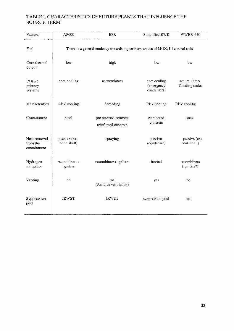
TABLE I. CHARACTERISTICS OF FUTURE PLANTS THAT INFLUENCE THESOURCE TERM
Feature
Fuel
Core thermaloutput
Passiveprimarysystems
Melt retention
Containment
Heat removalfrom thecontainment
Hydrogenmitigation
Venting
Suppressionpool
AP600
There is a
low
core cooling
RPV cooling
steel
passive (ext.cont. shell)
recombiners+igniters
no
IRWST
EPR Simplified BWR WWER-640
general tendency towards higher burn-up use of MOX, Hf control rods
high
accumulators
Spreading
pre-stressed concrete
reinforced concrete
spraying
recombiners+ igniters
no(Annulus ventilation)
IRWST
low
core cooling(emergencycondensers)
RPV cooling
reinforcedconcrete
passive(condenser)
inerted
yes
suppression pool
low
accumulators,flooding tanks
RPV cooling
steel
passive (ext.cont. shell)
recombiners(igniters?)
no
no
33
8.3. EVOLUTIONS IN FUEL AND CORE DESIGNS
In addition to plant design, the evolution of fuel and core design may have an impact on thein-containment source term. According to present trends, new plants will be introduced veryslowly in the next century for economic reasons but new fuel development may be quiteextensive because of the large number of existing plants. It is therefore worthwhile to considerthe potential for innovation in the light of its impact on the source term.
A change that is desirable for future fuel designs is that the fuel cycle will be consideredas a whole entity and not as many separate parts. All parts of the fuel cycle have an effect oneach other and will not be considered in isolation. This holistic approach means that fuels willbe designed so that the nuclear utility and its customers will receive the largest possibleeconomic benefit by virtue of a framework of a fuel cycle which is optimized in terms of thetotal cost. It may be expected that future fuels will be easier and cheaper to manufacture, aswell as to reprocess or to store, and will provide an overall environmental impact that is aslow as reasonably achievable (ALARA). Nevertheless, it is expected that advanced fuel cyclesshould make maximum use of fissile materials. At present, thermal reactors use only about3% of the original fissile material in their fuel.
This philosophy provides a driver for the definition of source terms for future reactorsystems. It is expected that the following fuel design issues will impact the source term:
— fuel discharge buraup targets will be set at optimum levels, up to 60 000 (MW-d/t U)which increases the fission product inventory (proportional for the long lived nuclides)and increases the release rates (see Section 4);
— MOX fuel cycles will be more widespread with potential consequences on the Pu sourceterm;
— extended use of more burnable absorbers (limited to 2-5% of a PWR and to 50% of aBWR core) with a potential consequence on release rate;
— new rod control cluster assembly (RCCA) designs;
— more RCCAs will be required (for MOX cycles especially). The choice of control rodmaterial has two effects on the source term,
• provides a source of inactive aerosols (Cd, Ag, H3BO3, etc.),
• influences the liquefaction temperature and thus the relevant melting temperature(B4C probably leading to the lowest, and Ha to highest temperature to be consideredfor fission product release),
• cladding changes based on fuel rod performance considerations. Stainless steelcladding may be considered in this context with some advanced core designs (highconversion reactor). Whereas the hydrogen production (by steam) is quite similar toreactions with Zircaloy cladding, the amount of associated heat, and therefore alsothe heat-up rate of the core, is much smaller.
9. CONCLUSIONS
The important phenomena which determine both the source term to the containment andthe in-containment source term have been addressed. A deterministic approach has beenadopted so that guidance has been provided for the relevant phenomena. However, it has beenrecognized that future designs and accident management measures will reduce to very low
34
values the probability that the vessel will fail at a high reactor coolant circuit pressure andthus, no details have been provided for phenomena that are specifically associated with thesesequences.
In the case of both the release to the containment and the behaviour of fission productsin the containment, a reasonably bounding approach has been proposed. Numerical values arenot given, but a parametric approach has been adopted which will enable to evaluate thesource term to the containment. The proposed approach is equally applicable to existing andfuture generation reactors, but the features that are specific to some future generation designshave been identified.
The major uncertainties which affect the evaluation of the source term to thecontainment and the in-containment source term have been identified together with theassociated R&D requirements.
Therefore, all the objectives that are identified in Section 1 have been met.
9.1. FUEL DESIGN AND CORE INVENTORY
It is recommended that the core inventory of fission products and actinides be evaluatedusing one of the recognized core inventory computer codes. These codes and their associateddatabases have been validated for current core and fuel designs and fuel managementstrategies.
However, it is anticipated that future developments will extend beyond the existingrange of validation. Thus, additional validation will be required or engineering judgement willneed to be applied which reasonably bounds the associated uncertainties.
9.2. THERMAL HYDRAULICS AND CORE DEGRADATION CONSIDERATIONS
(1) Design differences between current and future plants that may be important for thethermal hydraulics of core degradation are:
• increased water inventory;• lower power levels;• higher discharge burnups;• depressurization of the primary circuit;• heat removal from the containment;• passive flooding of the core or the basement of the containment.
(2) A LOCA with no intervention of the ECCS seems to be an appropriate representativesequence to evaluate for determining a reference source term for future reactors.
(3) It is useful to develop simple algorithms for evaluating the effects of different designfeatures on the thermal-hydraulic behaviour important to source term evaluation.
9.3. IN-VESSEL SOURCES
(1) The simple thermal-hydraulic algorithms developed in Section 3 need to be used alongwith a stand-alone fission product/aerosol model to predict the release from the core.Specific models may be required to describe the late-phase release of tellurium andantimony retained in Zircaloy up to 90% oxidation.
(2) The chemical forms of the fission products that may be released from the RCS for futurecore designs are likely to be the same as for current core designs.
35
(3) There are large uncertainties associated with release of materials from control rods andstructures and there is a justification for excluding one or both of these from the sourceterm specification. The effect of neglecting the latter is expected to be generallyconservative with respect to the robustness of the containment design. Whilst it may bepossible to exclude cadmium because of its release early in the accident, the lowvolatility of silver means that there will be a release over a longer period of time. Thiswill have a significant impact on the containment aerosol behaviour, as well as on theaqueous containment iodine behaviour. Therefore additional considerations of thesephenomena may be needed, particularly if they impact the function of importantsystems.
(4) The role of boric acid from the primary coolant (PWR) or from the B4C control blades(BWR) should also be considered. This has the potential of influencing the caesium andiodine species formed, and may also affect the containment sump pH.
(5) Whilst the largest release of radioactive products from a molten pool is likely to takeplace when it is sparged, there is experimental evidence that release will take placewhere there is no sparging. These data therefore require further assessment.
(6) There is not a unique sequence which results in both a bounding fission product releaseand the highest concentration of hydrogen in the containment. The intention of thepresent report is to provide a reasonably bounding value for the latter.
9.4. EFFECTS OF THE RCS ON FISSION PRODUCT BEHAVIOUR
For a low pressure sequence, it is considered reasonable to neglect the effects of theRCS on the reference source term.
9.5. EX-VESSEL SOURCES
(1) The strategy of depressurizing the reactor coolant circuit before the vessel leads to avery low probability of high pressure melt ejection and direct containment heating.Their contribution to the source term for design purposes can be neglected.
(2) If the probability of molten core-concrete interactions is not very low or if concrete isused as a sacrificial material in a core retention device which also will result in sparging,the molten core-concrete interactions must be addressed. The phenomenon is wellunderstood and several codes which have been validated by representative experimentalprogrammes are recommended. These may require significant modification forapplication to any catcher material other than concrete and which also results insparging.
9.6. IN-CONTAINMENT BEHAVIOUR
9.6.1. Important phenomena
(1) The most important aspects which affect the in-containment source term are the rate ofaerosol deposition, the behaviour of gaseous iodine, the effect of the spray system and,in the case of accidents where the release to the containment is via a water pool, thedecontamination factor due to pool scrubbing.
(2) The rate of aerosol deposition with respect to agglomeration and the subsequentgravitational settling can always be assured and credit is taken for these phenomena inthe reference source term. They are, however sensitive to the particle size distribution.Because the thermal hydraulic behaviour in the containment is sequence specific, no
36
credit is taken for the rate of particle growth due to condensation on the aerosol. Thelatter is also sensitive to the solubility of the initial aerosol.
(3) The production of gaseous iodine is sensitive to the pH of both the aqueous phasesnamely the aqueous aerosol and the water pools, and will be minimized if the pH of thesump water is controlled to be 8 or greater.
(4) The decontamination factor associated with pool scrubbing is sensitive to the velocity,steam content and size distribution of the aerosol, the flow regime within the water pooland whether or not the pool is boiling.
(5) A spray system can be a very effective means of removing fission products from the in-containment source term. Its effectiveness is sensitive to the size distribution of both thespray droplets and the aerosol. The effectiveness increases as the size of the spraydroplets decreases and has a minimum for an aerosol size of approximately 1 micron.
9.6.2. Major uncertainties
(1) If the sump pH is controlled at or greater than 8, the consensus of expert opinion is thatthe iodine can be modelled as if it behaves as an aerosol. The major uncertaintyassociated with this approach is the effect of acid formation in the containmentatmosphere on the pH of the aqueous aerosol. There is a requirement to determine andmodel the importance of this effect and the potential for the formation of Agl to retainiodine in the aqueous phases.
(2) If the sump pH is not controlled, there is a requirement to perform a reasonablyconservative evaluation of the pH of the aqueous aerosol and water pools and toevaluate the behaviour of the volatile forms of iodine and their contribution to therelease from the containment. The main uncertainties are the constituents of the aqueousphases as a function of time, which govern the pH, and the ability of reactions withsilver to retain iodine in an involatile form. For designs where the pH is not controlled,there is a requirement to develop modelling for both these effects.
(3) There is a good database for pool scrubbing in bubbly conditions which are applicableto many BWR conditions but there are less data for churn turbulent conditions. Thus,the major uncertainties associated with pool scrubbing are the size distribution of theaerosol, decontamination factors in churn-turbulent regimes and the effect of saturatedand boiling pools.
9.7. THE DESIGN OF NEW GENERATION PLANTS AND FUELS
Some aspects of the designs of both the designs of new generation plants and their fuelsare expected to have a significant impact on the source term. Because it is a requirement toaddress severe accidents in the design of future reactors, the overall effect of changes in theplant design is expected to reduce the source term. Some of the anticipated changes to thedesign of the fuel and its management are expected to increase the fission product and actinideinventories, but source term considerations are not expected to rule out any developments thatare currently envisaged.
Examples of potential changes with respect to the design are:
— an increased water inventory in the RCS which will delay the time at which the releasefrom the fuel occurs and
— quenching of the molten corium if it penetrates the reactor pressure vessel which willgreatly reduce the probability of any ex-vessel contribution to the source term.
37

Examples of potential changes with respect to the fuel are;
— higher burnups than are utilized today and
— changes to the designs of the control rods and burnable poisons and the introduction ofnew cladding designs.
Some of the developments in fuel design may extend beyond the existing range ofvalidation of the codes and data that are used to evaluate the core inventory. Thus, anextension to the validated database will be required.
38
REFERENCES
[I] DUTTON, L.M.C., JONES, S.H.M, EYTNK, J., Plant Assessments, Identification ofUncertainties in Source Term Analysis, European Commission, EUR 16502 EN,Luxembourg (1995).
[2] NUCLEAR REGULATORY COMMISSION, Severe Accident Risks: An Assessmentfor Five US Nuclear Power Plants, Rep. NUREG-1150, Division of Systems Research,Washington, DC (1990).
[3] NUCLEAR REGULATORY COMMISSION, Individual Plant Examination for SevereAccident Vulnerabilities, Generic Letter 88-20 of 23 Nov 1988, USNRC, Washington,DC.
[4] WRIGHT, A.L., Primary System Fission Product Release and Transport, Rep.NUREG/CR-6193 Oak Ridge Nat. Labs, TN (1994).
[5] NUCLEAR REGULATORY COMMISSION, Reactor Safety Study an Assessment ofAccident Risk in US Commercial Nuclear Power Plants, WASH-1400 (NUREG-75/014), Washington, DC (1975).
[6] SOFFER, L., BURSON, S.B., FERRELL, CM., LEE, R.Y., RIDGLEY, J.N., AccidentSource Terms for Light-Water Nuclear Power Plants, Rep. NUREG-1465 Division ofSystems Technology, Washington, DC (1995).
[7] PAWEL, R.E., CATHCART, J.V., MCKEE, R.A., The kinetics of oxidation ofZircaloy-4 in steam at high temperatures, J. Electrochem. Soc. 126 7 (1979) 1105-1 111.
[8] DUTTON, L.M.C., HANDY, B.J., SMEDLEY, C, STEPHENSON, W., RealisticMethods for Calculating the Releases and Consequences of a Large LOCA, EuropeanCommission, EUR 14179 EN, Luxembourg (1992).
[9] BOWSHER, B.R., AEA Technology, Winfrith, private communication (1987).[10] ALEXANDER, C.A., OGDEN, J.S., J. Nucl. Mat. 175 197 (1990).[II] BOWSHER, B.R., NICHOLS, A.L., Ag-In-Cd Control rod behaviour during a severe
accident in a pressurised water reactor, High Temperature. Matls Science 33 25 (1995).[12] BOWSHER, B.R., JENKINS, R.A. NICHOLS, A.L., ROWE, N.A., SIMPSON, J.A.H,
AEA Technology Report AEEW-R 1991 (1986).[13] PETTI, D.A., Silver-indium-cadmium control rod behaviour in severe reactor
accidents, Nuclear Technology 84 128 (1989).[14] BEATTJJE, I.R., Fission Product Transport in Reactor Accidents (ROGERS, J.T., Ed.),
Hemisphere Publishing Corporation, New York (1990) 447 pp.[15] BOWSHER, B.R., Fission-product chemistry and aerosol behaviour in the primary
circuit of a pressurized water reactor under severe accident conditions, Prog. NuclearEnergy 20 199(1987).
[16] ELRICK, R.M., SALLACH, R.A, "Fission product chemistry in the primary system",International Meeting on LWR Severe Accident Evaluation, Cambridge, MA (1983).
[17] ANDERSON, A.B., BEARD, A.M., BENNETT, P.J., BENSON, C.G., Report AEATechnology Reactor Services, Winfrith, UK, TRS 5091 (1991).
[18] ADAMS, R.E., TOBIAS., M.L., Rep. NUREG/CR-3830 Vol. 1, Oak Ridge NationalLab., TN (1984).
[19] PARKER, G.W., Proceedings of ACS. Symp. on Chemical Phenomena Associated withRadioactivity Release During Sever Nuclear Plant Accidents (1986), Anaheim, Rep.NUREG/CP-0078 (1987).
[20] MAGALLON, D., et al., High Temperature Melt/Water Mixing: Results andCalculations of FARO Premix and Mixa Experiments, FISA 95 — EU Research onSevere Accidents (VAN GOETHEM, G., BALTZ, W., DELLA LOGGIA, E., Eds),CEC Report EUR 16896 EN 140 Luxembourg (1996).
39
[21] MAGALLON, D., et al., Characterization of Processes which Govern Quenching ofMolten Corium in Water, Including Steam Explosion (MFCI) FISA 97-EU Research onSevere Accidents (VAN GOETHEM, G... KEINHORST, G., MARTIN BERMEJO J.,ZURITA, A., Eds), CEC Report EUR 18258 EN 93 Luxembourg (1998).
[22] BENSON, C.G., KEMP C.C., NEWLAND, M.S., Fission Product Release from MoltenPools: Interim Data Report, AEA Technology Report AEAT-3777 (1998).
[23] PETROV, YU.B., et al., "Fission product release from molten pool: ceramic melt tests",Workshop on Severe Accident Research held in Tokyo (SARJ-98), Japan AtomicResearch Institute, Tokyo (1998).
[24] MAAP 3.0b Computer Code Manual, Fauske & Associates, EPRI NE 7071-CCML,Palo Alto, CA( 1990).
[25] POWERS, D.A., BURSON, S.B., A Simplified Method of Aerosol Removal byContainment Sprays, Rep. NUREG/CR-5966 (SAND92-2689), Sandia National Labs,Albuquerque, NM (1993).
[26] POWERS, D.A., and SPRUNG, J.L., A Simplified Model of Aerosol Scrubbing by aWater Pool Overlying Core Debris Interacting with Concrete, Rep. NUREG/CR-5901(SAND92-1422), Sandia National Labs, Albuquerque, NM (1993).
[27] RAMSDALE, S., GUNTAY, S., FRIEDERICHS, H-G., BUSCA-June 91 ReferenceManual, Paul Scherrer Institute (PSI), Villigen, Bericht Nr.: 95-05 (1995).
[28] OWCZARSKI, P.C., POSTMA, A.K., SCHRECK, R.I., Technical Bases and User'sManual for the Prototype of SPARC — A Suppression Pool Aerosol Removal Code,Rep. NUREG/CR-3317 (PNL-4742), Pacific Northwest Labs., Richland, WA (1985).
[29] BURNS, W.G., SIMS, H.E., "The use of the facsimile program in the speciation ofiodine in a PWR reactor containment following a loss of coolant", Proc. of the secondCSNI Workshop on iodine chemistry in reactor safety, 1988, Toronto, Canada, AECL-9923, Toronto (1989).
[30] CURTIS, A.R., SWEETENHAM, W.P., FACSMILE/CHECKMAT User's Manual,AERE-R12805, Atomic Energy Research Establishment, Harwell (1988).
[31] GAUVAIN, J., PEPIN, P., FELIPPI, M., Systeme ESCADRE-Code IODE, Version-2,"Transferts d'iode dans l'enceinte d'un reacteur lors d'un accident grave", Rapporttechnique SASC/89/66, Commissariat a l'Energie Atomique (CEA), Fontenay-aux-Roses(1989).
[32] GAUVAIN, J., et al., IODE 2.0 User Manual, Rapport technique SEAC/91/04,Commissariat a l'Energie Atomique (CEA), Fontenay-aux-Roses.
[33] CRIPPS, R., FURRER, M., HELLMANN, S., FUNKE, F., User's Handbook for theIodine Severe Accident Behaviour Code IMPAIR 2.2, PSI-Bericht Nr.114, PaulScherrer Institute (PSI), Villigen (1992).
[34] GUNTAY, S., CRIPPS, R., IMPAIRy3: A Computer Program to Analyse the IodineBehaviour in Multi-compartments of a LWR Containment, PSI-Bericht Nr. 128, PaulScherrer Institute (PSI), Villigen (1992).
[35] BEAHM, E.C., et al., "Chemistry and mass transfer of iodine in containment", Proc.2nd CSNI Workshop on iodine chemistry in reactor safety, Toronto, ON (1988), AECL-9923, CSNI-149, Toronto (1988).
[36] WREN, J.C., SAGERT, N.H., SIMS, H.E., "Modelling of iodine chemistry: The LIRICdatabase", Proc. 3rd CSNI Workshop on Iodine Chemistry in Reactor Safety,ISHIGURE, K.J., Tokyo Univ., Japan, SAEKI, M., SODA, K., SUGIMOTO, J. (Eds.).Japan Atomic Energy Research Inst., Tokyo, Japan (1991), JEARI-M 92-012,NEA/CSNI/R(91)15, Tokai (1991).
40

[37] SIMS, H.E., et al., Reinforced Concerted Action on Reactor Safety; Source TermProject: Iodine Code Comparison, CEC Contract F13S-CT92-0006, ST(93)-P75,published as a EURATOM report, Brussels (1993).
[38] DUTTON, L.M.C., et al., Iodine Behaviour in Severe Accidents, EuropeanCommission, Contract FT3S-CT93-OOO9, ST(95)-P105 Issue V05, published as aEURATOM report, Brussels (1995).
41
Appendix
APPLICATION EXAMPLE FOR THE SIMPLIFIEDSOURCE TERM METHODOLOGY
A.I. INTRODUCTION
The TECDOC to which this appends proposes a simplified source term methodology asbeing a viable approach for developing plant specific design source terms. The proposedmethodology uses simple algorithms to quantify an associated reference sequence"generalised thermal transient" that is to be used along with an appropriate fission productrelease model to develop the source term. The method is intended to accommodate differentdesign options for future nuclear power plants (NPPs).
The proposal spelled out in the TECDOC is an innovative approach not known to havebeen used previously. Consequently, this appendix was developed to provide an exampleapplication of the methodology — hopefully to demonstrate its validity and usefulness.
The approach taken in this appendix for the application of the example was to develop aPC computer model for quantification of the proposed "generalized thermal transient" ofSection 3 using the simple algorithms suggested. The computer model developed [SimplifiedSource Term (SST)] required a fission product release model to "translate" the generalizedthermal transient into the desired source term. Two optional models for fission product releasewere included in SST: (1) the CORSOR-M model currently in MELCOR, and (2) a newmodel called the Kress/Booth RelVol model.
The CORSOR-M model was included in SST to allow benchmarking the derived sourceterm because the CORSOR-like models were used [along with the Source Term CodePackage (STCP) and along with MELCOR] to "initialize" best-estimate values for the expertelicitation process of NUREG-1150 that went into quantifying the STs and uncertainties onwhich the NUREG-1465 source terms were based.
The new RelVol model was included because of the now widely known tendency for thevarious CORSOR models to significantly overestimate the releases of volatile fission productscompared with experimental data and with the calculated results of more sophisticated fissionproduct release models such as FASTGRASS. In addition, the RelVol model includes acorrelation for the effects of burnup which will be required if SST is to be used for estimatingsource terms for future NPPs (CORSOR does not have such a correlation). The RelVol fissionproduct release model is much more accurate in predicting experimental data for fissionproduct release than is CORSOR and is just as easy to implement.
The Kress/Booth aspect of RelVol for Cs release was developed as a stand-alone model(called ASSTCs) that will accept arbitrary thermal transient input (as a series of linearfunctions) for purposes of comparison with experimental data. This ASSTCs Kress/Boothmodel was then compared with the Cs release results from the ORNL VI-3 experiment toillustrate the validity and accuracy of the model.
The SST code, with the complete Kress/Booth RelVol and the CORSOR-M models,was used to develop the source term for a large-break loss of coolant accident (LBLOCA)sequence for the SURRY PWR plant. SURRY was selected for this example applicationbecause it was one of the reference plants used in NUREG-1150 on which the PWR sourceterm in NUREG-1465 was based. The resulting calculated source terms using both RelVoland CORSOR-M were then compared with the NUREG-1465 values to illustrate the efficacyof the simplified source term methodology.
43
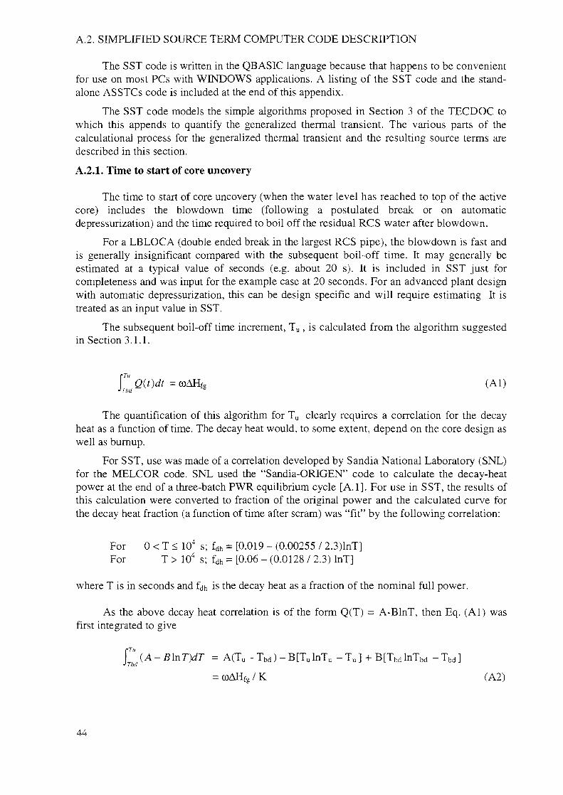
A.2. SIMPLIFIED SOURCE TERM COMPUTER CODE DESCRIPTION
The SST code is written in the QBASIC language because that happens to be convenientfor use on most PCs with WINDOWS applications. A listing of the SST code and the stand-alone ASSTCs code is included at the end of this appendix.
The SST code models the simple algorithms proposed in Section 3 of the TECDOC towhich this appends to quantify the generalized thermal transient. The various parts of thecalculational process for the generalized thermal transient and the resulting source terms aredescribed in this section.
A.2.1. Time to start of core uncovery
The time to start of core uncovery (when the water level has reached to top of the activecore) includes the blowdown time (following a postulated break or on automaticdepressurization) and the time required to boil off the residual RCS water after blowdown.
For a LBLOCA (double ended break in the largest RCS pipe), the blowdown is fast andis generally insignificant compared with the subsequent boil-off time. It may generally beestimated at a typical value of seconds (e.g. about 20 s). It is included in SST just forcompleteness and was input for the example case at 20 seconds. For an advanced plant designwith automatic depressurization, this can be design specific and will require estimating It istreated as an input value in SST.
The subsequent boil-off time increment, Tu , is calculated from the algorithm suggestedin Section 3.1.1.
(Al)
The quantification of this algorithm for Tu clearly requires a correlation for the decayheat as a function of time. The decay heat would, to some extent, depend on the core design aswell as burnup.
For SST, use was made of a correlation developed by Sandia National Laboratory (SNL)for the MELCOR code. SNL used the "Sandia-ORIGEN" code to calculate the decay-heatpower at the end of a three-batch PWR equilibrium cycle [A.I]. For use in SST, the results ofthis calculation were converted to fraction of the original power and the calculated curve forthe decay heat fraction (a function of time after scram) was "fit" by the following correlation:
For 0 < T < 104 s; fdh = [0.019 - (0.00255 / 2.3)lnT]For T > 104 s; fdh = [0.06 - (0.0128 / 2.3) lnT]
where T is in seconds and f is the decay heat as a fraction of the nominal full power.
As the above decay heat correlation is of the form Q(T) = A-BlnT, then Eq. (Al) wasfirst integrated to give
P (A-BlnT)dT = A(TU - Tbd) -B[TulnTu - T u ] + B[TbdlnTbd - T b d ]r•> Tbd
= coAHfg / K (A2)
44
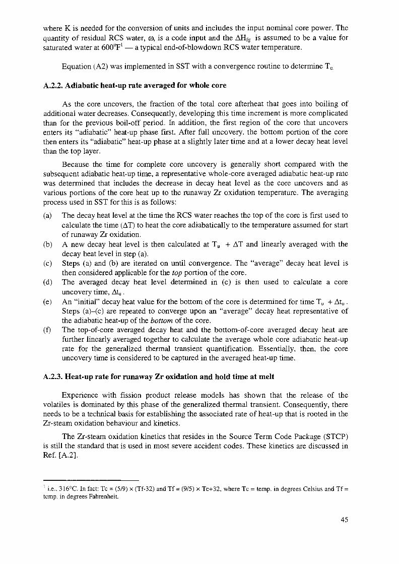
where K is needed for the conversion of units and includes the input nominal core power. Thequantity of residual RCS water, co, is a code input and the AHfg is assumed to be a value forsaturated water at 600°F' — a typical end-of-blowdown RCS water temperature.
Equation (A2) was implemented in SST with a convergence routine to determine Tu.
A.2.2. Adiabatic heat-up rate averaged for whole core
As the core uncovers, the fraction of the total core afterheat that goes into boiling ofadditional water decreases. Consequently, developing this time increment is more complicatedthan for the previous boil-off period. In addition, the first region of the core that uncoversenters its "adiabatic" heat-up phase first. After full uncovery, the bottom portion of the corethen enters its "adiabatic" heat-up phase at a slightly later time and at a lower decay heat levelthan the top layer.
Because the time for complete core uncovery is generally short compared with thesubsequent adiabatic heat-up time, a representative whole-core averaged adiabatic heat-up ratewas determined that includes the decrease in decay heat level as the core uncovers and asvarious portions of the core heat up to the runaway Zr oxidation temperature. The averagingprocess used in SST for this is as follows:
(a) The decay heat level at the time the RCS water reaches the top of the core is first used tocalculate the time (AT) to heat the core adiabatically to the temperature assumed for startof runaway Zr oxidation.
(b) A new decay heat level is then calculated at Tu + AT and linearly averaged with thedecay heat level in step (a).
(c) Steps (a) and (b) are iterated on until convergence. The "average" decay heat level isthen considered applicable for the top portion of the core.
(d) The averaged decay heat level determined in (c) is then used to calculate a coreuncovery time, Atu.
(e) An "initial" decay heat value for the bottom of the core is determined for time Tu + Atu.Steps (a)-(c) are repeated to converge upon an "average" decay heat representative ofthe adiabatic heat-up of the bottom of the core.
(f) The top-of-core averaged decay heat and the bottom-of-core averaged decay heat arefurther linearly averaged together to calculate the average whole core adiabatic heat-uprate for the generalized thermal transient quantification. Essentially, then, the coreuncovery time is considered to be captured in the averaged heat-up time.
A.2.3. Heat-up rate for runaway Zr oxidation and hold time at melt
Experience with fission product release models has shown that the release of thevolatiles is dominated by this phase of the generalized thermal transient. Consequently, thereneeds to be a technical basis for establishing the associated rate of heat-up that is rooted in theZr-steam oxidation behaviour and kinetics.
The Zr-steam oxidation kinetics that resides in the Source Term Code Package (STCP)is still the standard that is used in most severe accident codes. These kinetics are discussed inRef. [A.2].
1 i.e., 316°C. In fact: Tc = (5/9) x (Tf-32) and Tf = (9/5) x Tc+32, where Tc = temp, in degrees Celsius and Tf =temp, in degrees Fahrenheit.
45
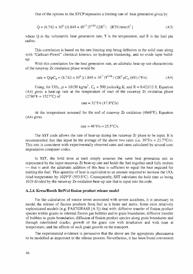
One of the options in the STCP represents a limiting rate of heat generation given by
Q = (8.742 x 10⁶)(1.849 x 1CT7 )T068/(2R2) [BTU/min.ft3 ] (A3)
where Q is the volumetric heat generation rate, T is the temperature, and R is the fuel pinradius.
This correlation is based on the rate limiting step being diffusion in the solid state alongwith "Cathcart-Powel" chemical kinetics, no hydrogen blanketing, and no oxide layer build-up.
With this correlation for the heat generation rate, an adiabatic heat-up rate characteristicof the runaway Zr oxidation phase would be
rate = Q/pCp = (8.742 x 10⁶)(1.849 x 10"7 )T068 / (2R2 pCp )(60) (°F/s) (A4)
Using, for UO2, p = 10150 kg/m3, Cp = 500 joules/kg.K, and R = 0.422/12 ft, Equation(A4) gives a heat-up rate at the temperature of start of the runaway Zr oxidation phase(2780°F= 1527°C)of
rate = 32°F/s(17.8°C/s)
At the temperature assumed for the end of runaway Zr oxidation (4868°F), Equation(A4) gives
rate = 46°F/s = 25.5°C/s.
The SST code allows the rate of heat-up during the runaway Zr phase to be input. It isrecommended that this input be the average of the above two rates (i.e. 39°F/s = 21.7°C/s).This rate is consistent with experimentally observed rates and rates calculated by several coredegradation computer codes.
In SST, the hold time at melt simply assumes the same heat generation rate asrepresented by the input runaway Zr heat-up rate and holds the fuel together until fully molten— that is until the adiabatic addition of this heat is sufficient to equal the heat required formelting the fuel. This quantity of heat is equivalent to an amount required to increase the UOo/clad temperature by 1029°F (553.9°C). Consequently, SST calculates the hold time as being1029 divided by the runaway Zr-oxidation heat-up rate that is input into the code.
A.2.4. Kress/Booth RelVoI fission product release model
For the calculation of source terms associated with severe accidents, it is necessary tomodel the release of fission products from fuel as it heats and melts. Some exist relativelysophisticated models (e.g. FASTGRASS [A.3]) deal with: diffusive transfer of fission productspecies within grains to internal fission gas bubbles and to grain boundaries; diffusive transferof bubbles to grain boundaries; diffusion of fission product species along grain boundaries andthrough interlinked cracks; growth of the grain size with irradiation and with time attemperature, and the effects of such grain growth on the transport.
The experimental evidence is persuasive that the above are the appropriate phenomenato be modelled as important in the release process. Nevertheless, it has been found convenient
46
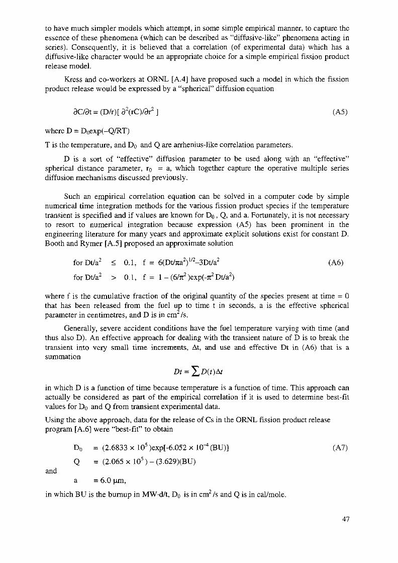
to have much simpler models which attempt, in some simple empirical manner, to capture theessence of these phenomena (which can be described as "diffusive-like" phenomena acting inseries). Consequently, it is believed that a correlation (of experimental data) which has adiffusive-like character would be an appropriate choice for a simple empirical fission productrelease model.
Kress and co-workers at ORNL [A.4] have proposed such a model in which the fissionproduct release would be expressed by a "spherical" diffusion equation
ac/dt = (D/r)[ 92(rC)/3r2 ] (A5)
where D = Doexp(-Q/RT)
T is the temperature, and Do and Q are arrhenius-like correlation parameters.
D is a sort of "effective" diffusion parameter to be used along with an "effective"spherical distance parameter, ro = a, which together capture the operative multiple seriesdiffusion mechanisms discussed previously.
Such an empirical correlation equation can be solved in a computer code by simplenumerical time integration methods for the various fission product species if the temperaturetransient is specified and if values are known for Do, Q, and a. Fortunately, it is not necessaryto resort to numerical integration because expression (A5) has been prominent in theengineering literature for many years and approximate explicit solutions exist for constant D.Booth and Rymer [A.5] proposed an approximate solution
forDt/a2 < 0.1, f = 6(Dt/7ta2)1/2-3Dt/a2 (A6)
forDt/a2 > 0.1, f = 1 - (6/jt2 )exp(-7t2 Dt/a2)
where f is the cumulative fraction of the original quantity of the species present at time = 0that has been released from the fuel up to time t in seconds, a is the effective sphericalparameter in centimetres, and D is in cm2/s.
Generally, severe accident conditions have the fuel temperature varying with time (andthus also D). An effective approach for dealing with the transient nature of D is to break thetransient into very small time increments, At, and use and effective Dt in (A6) that is asummation
in which D is a function of time because temperature is a function of time. This approach canactually be considered as part of the empirical correlation if it is used to determine best-fitvalues for Do and Q from transient experimental data.
Using the above approach, data for the release of Cs in the ORNL fission product releaseprogram [A.6] were "best-fit" to obtain
Do = (2.6833 x 10⁵)exp[-6.052 x 10""* (BU)] (A7)
Q = (2.065 x 10⁵) - (3.629)(BU)and
a = 6.0 um,
in which BU is the burnup in MW-d/t, Do is in cm2/s and Q is in cal/mole.
47
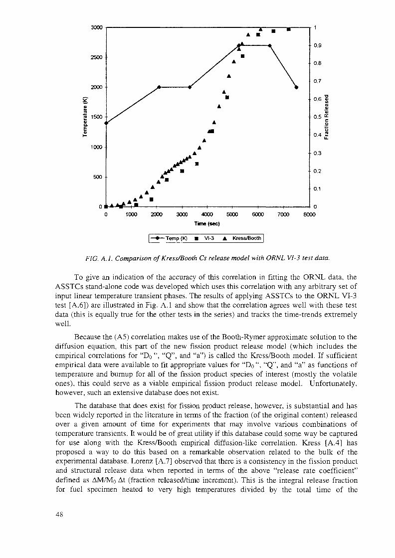
3000
1000 2000 3000 4000 5000 6000
Time (sec)
7000
0.1
0
8000
-Temp(K) • VI-3 A Kress/Booth
FIG. A.I. Comparison of Kress/Booth Cs release model with ORNL VI-3 test data.
To give an indication of the accuracy of this correlation in fitting the ORNL data, theASSTCs stand-alone code was developed which uses this correlation with any arbitrary set ofinput linear temperature transient phases. The results of applying ASSTCs to the ORNL VI-3test [A.6]) are illustrated in Fig. A.I and show that the correlation agrees well with these testdata (this is equally true for the other tests in the series) and tracks the time-trends extremelywell.
Because the (A5) correlation makes use of the Booth-Rymer approximate solution to thediffusion equation, this part of the new fission product release model (which includes theempirical correlations for "Do ", "Q", and "a") is called the Kress/Booth model. If sufficientempirical data were available to fit appropriate values for "Do ", "Q", and "a" as functions oftemperature and burnup for all of the fission product species of interest (mostly the volatileones), this could serve as a viable empirical fission product release model. Unfortunately,however, such an extensive database does not exist.
The database that does exist for fission product release, however, is substantial and hasbeen widely reported in the literature in terms of the fraction (of the original content) releasedover a given amount of time for experiments that may involve various combinations oftemperature transients. It would be of great utility if this database could some way be capturedfor use along with the Kress/Booth empirical diffusion-like correlation. Kress [A.4] hasproposed a way to do this based on a remarkable observation related to the bulk of theexperimental database. Lorenz [A.7] observed that there is a consistency in the fission productand structural release data when reported in terms of the above "release rate coefficient"defined as AM/Mo At (fraction released/time increment). This is the integral release fractionfor fuel specimen heated to very high temperatures divided by the total time of the
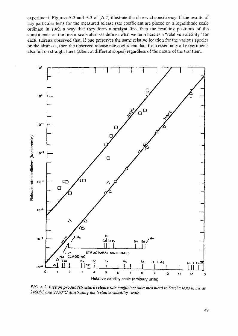
experiment. Figures A.2 and A.3 of [A.7] illustrate the observed consistency. If the results ofany particular tests for the measured release rate coefficient are placed on a logarithmic scaleordinate in such a way that they form a straight line, then the resulting positions of theconstituents on the linear-scale abscissa defines what we term here as a "relative volatility" foreach. Lorenz observed that, if one preserves the same relative location for the various specieson the abscissa, then the observed release rate coefficient data from essentially all experimentsalso fall on straight lines (albeit at different slopes) regardless of the nature of the transient.
to1
10"
0)[o"S3ooCD
2CDCOCO
"53or
1 0 "
1-6
f— CDD
Sn S b /Mn
Zr STRUCTURAI MATERIALSNd CLADDING
z'\ I N ! h » I I I I ISb T e l A9 Ci I Tr-2
3 « S 6 7 B 9
Relative volatility scale (arbitrary units)to 11
FIG. A.2. Fission product/structure release rate coefficient data measured in Sascha tests in air at2400°C and 2750°C illustrating the 'relative volatility' scale.
49
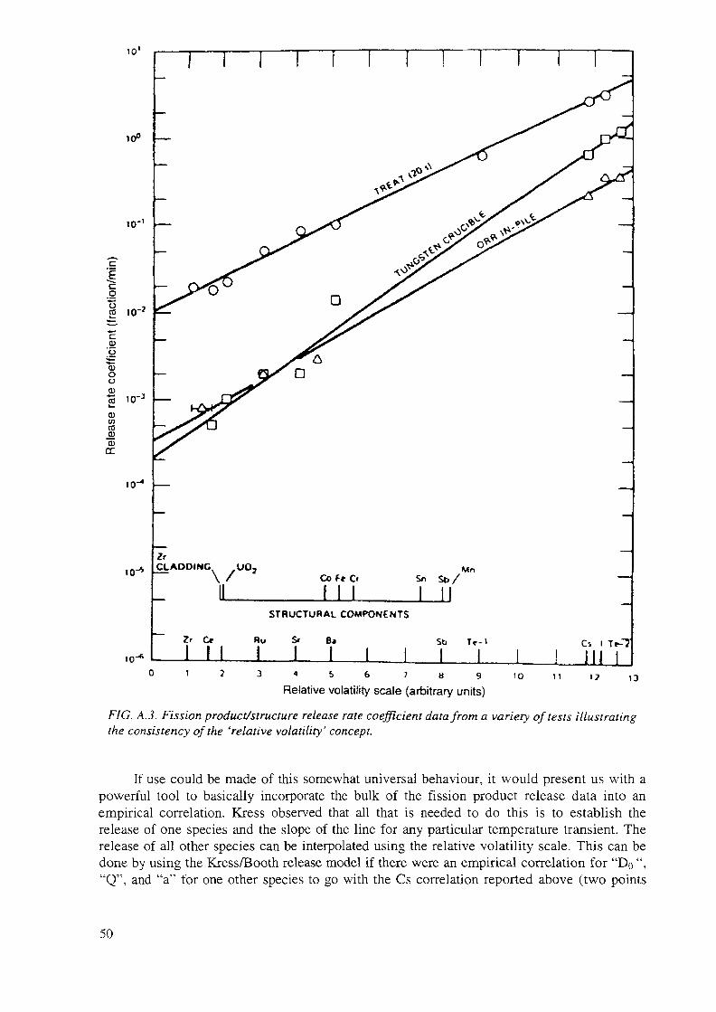
10'
10°
£
g75cC
CD
'oSo
enCO
10"
ro I0"3
10"
10"
T—i—i r
C_L ADDING yt>O2
Co ft C
JLLLS b /
Mn
Cr
1
STRUCTURAL COMPONENTS
Sr BJ Cs l
3 ^ 5 6 7 S 9 10
Relative volatility scale (arbitrary units)1? 13
FIG. A.3. Fission product/structure release rate coefficient data from a variety of tests illustratingthe consistency of the 'relative volatility' concept.
If use could be made of this somewhat universal behaviour, it would present us with apowerful tool to basically incorporate the bulk of the fission product release data into anempirical correlation. Kress observed that all that is needed to do this is to establish therelease of one species and the slope of the line for any particular temperature transient. Therelease of all other species can be interpolated using the relative volatility scale. This can bedone by using the Kress/Booth release model if there were an empirical correlation for "Do ","Q", and "a" for one other species to go with the Cs correlation reported above (two points
50

establish the slope of a straight line; we only need to know the release values for twoelements — we can then interpolate using the relative volatility scale to find the release valuesfor all the other constituents).
In the ORNL fission product release experiments, the experimental on-line time releasebehaviour of Cs was found by continuous reading of the downstream of the test chamber. Asthe real fuel specimens used in the test had aged considerably since their original irradiation,the activity measurements were dominated by Kr and Cs, so these were the only two elementsfor which continuous measurements were made. The "relative volatility" of Kr lies much tooclose to that of Cs for it to be a good second standard for the Kress/Booth model. Fortunately,the ORNL tests obtained limited time-correlated release data for other species by using threeseparate independent collection trains operated at different times during the tests. While thesedata are limited, they were sufficient to develop a best-fit Kress/Booth correlation forantimony as shown below.
For Sb:
a = 6 urn
Do =(3.4608xl06)exp[(-6.052xl0"4(BU)] (cm2/s) (A8)
Q = (2.494xlO5) - 3.629(BU) (cal/mole)
With the two standards (Cs and Sb) for the Kress/Booth model and the quantification ofthe generalized thermal transient, SST uses the "relative volatility" scale of Table A.I toestablish the fractional release of all species (hence the designation of the full fission productrelease model as being the Kress/Booth RelVol model).
TABLE A.I. RELATIVE VOLATILITY (RV)VALUES
Species groupNGTeI
CsSbBaSrRuLaCe
Structure materialsMnSbSnCrFeCo
uo2
RV1.11.07*1.031.000.680.420.340.250.140.085
0.690.680.630.470.440.410.17
*For oxidized clad.
51
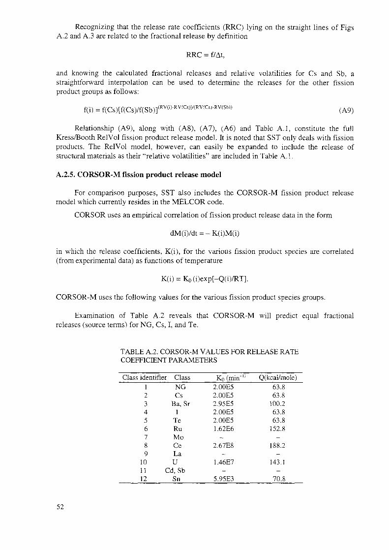
Recognizing that the release rate coefficients (RRC) lying on the straight lines of FigsA.2 and A.3 are related to the fractional release by definition
RRC = f/At,
and knowing the calculated fractional releases and relative volatilities for Cs and Sb, astraightforward interpolation can be used to determine the releases for the other fissionproduct groups as follows:
f(i) = f(Cs)[f(Cs)/f(Sb)](RV(l)-RV(Cs))/(RV(Cs)-RV(Sb)) (A9)
Relationship (A9), along with (A8), (A7), (A6) and Table A.I, constitute the fullKxess/Booth RelVol fission product release model. It is noted that SST only deals with fissionproducts. The RelVol model, however, can easily be expanded to include the release ofstructural materials as their "relative volatilities" are included in Table A. 1.
A.2.5. CORSOR-M fission product release model
For comparison purposes, SST also includes the CORSOR-M fission product releasemodel which currently resides in the MELCOR code.
CORSOR uses an empirical correlation of fission product release data in the form
dM(i)/dt = - K
in which the release coefficients, K(i), for the various fission product species are correlated(from experimental data) as functions of temperature
K(i) = Ko(i)exp[-Q(i)/RT].
CORSOR-M uses the following values for the various fission product species groups.
Examination of Table A.2 reveals that CORSOR-M will predict equal fractionalreleases (source terms) for NG, Cs, I, and Te.
TABLE A.2. CORSOR-M VALUES FOR RELEASE RATECOEFFICIENT PARAMETERS
Class identifier Class123456789
101112
NGCs
Ba, Sr1
TeRuMoCeLaU
Cd, SbSn
Ko (mirf °2.00E52.00E52.95E52.00E52.00E51.62E6
—2.67E8
—1.46E7
—5.95E3
Q(kcal/mole)63.863.8
100.263.863.8
152.8—
188.2—
143.1—
70.8
52
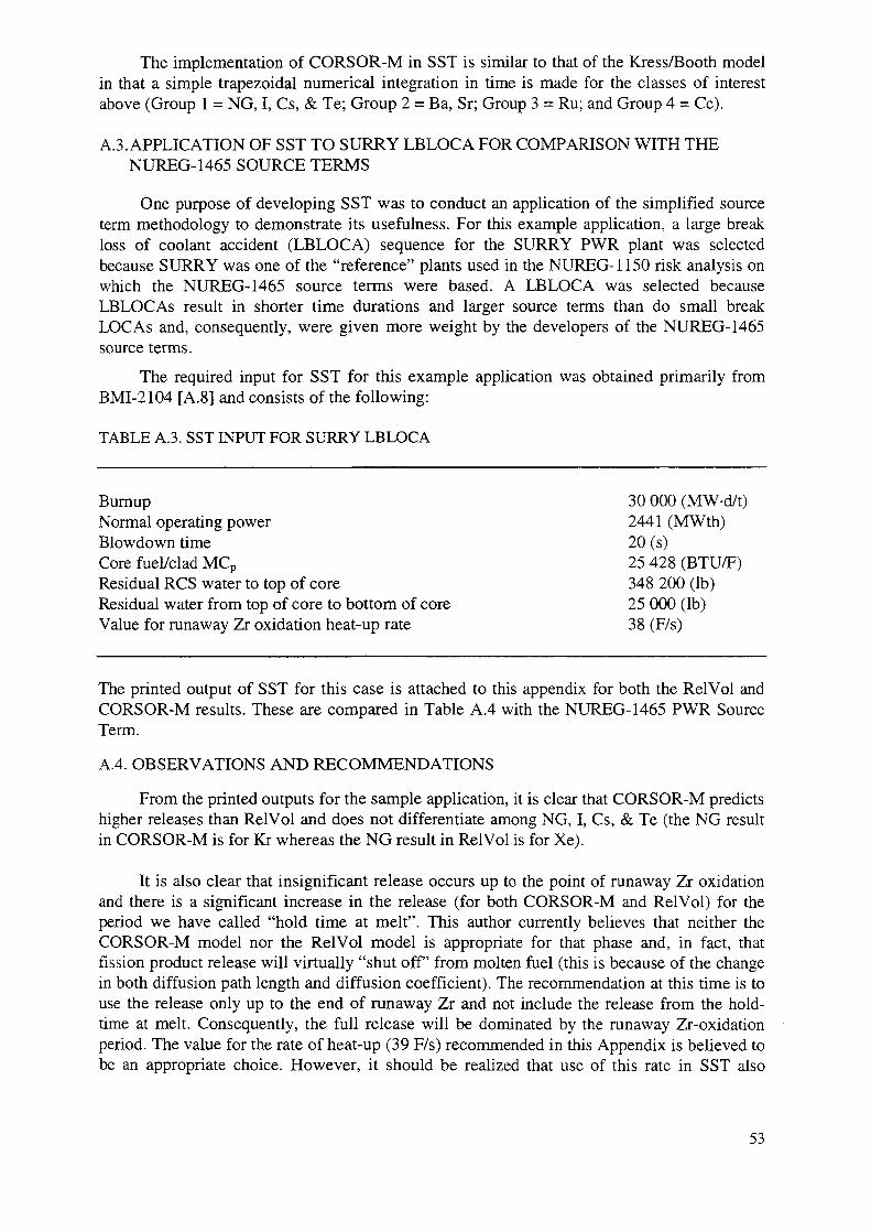
The implementation of CORSOR-M in SST is similar to that of the Kress/Booth modelin that a simple trapezoidal numerical integration in time is made for the classes of interestabove (Group 1 = NG, I, Cs, & Te; Group 2 = Ba, Sr; Group 3 = Ru; and Group 4 = Ce).
A.3. APPLICATION OF SST TO SURRY LBLOCA FOR COMPARISON WITH THENUREG-1465 SOURCE TERMS
One purpose of developing SST was to conduct an application of the simplified sourceterm methodology to demonstrate its usefulness. For this example application, a large breakloss of coolant accident (LBLOCA) sequence for the SURRY PWR plant was selectedbecause SURRY was one of the "reference" plants used in the NUREG-1150 risk analysis onwhich the NUREG-1465 source terms were based. A LBLOCA was selected becauseLBLOCAs result in shorter time durations and larger source terms than do small breakLOCAs and, consequently, were given more weight by the developers of the NUREG-1465source terms.
The required input for SST for this example application was obtained primarily fromBMI-2104 [A.8] and consists of the following:
TABLE A.3. SST INPUT FOR SURRY LBLOCA
Burnup 30 000 (MW-d/t)Normal operating power 2441 (MWth)Blowdown time 20 (s)Core fuel/clad MCP 25 428 (BTU/F)Residual RCS water to top of core 348 200 (lb)Residual water from top of core to bottom of core 25 000 (lb)Value for runaway Zr oxidation heat-up rate 38 (F/s)
The printed output of SST for this case is attached to this appendix for both the RelVol andCORSOR-M results. These are compared in Table A.4 with the NUREG-1465 PWR SourceTerm.
A.4. OBSERVATIONS AND RECOMMENDATIONS
From the printed outputs for the sample application, it is clear that CORSOR-M predictshigher releases than RelVol and does not differentiate among NG, I, Cs, & Te (the NG resultin CORSOR-M is for Kr whereas the NG result in RelVol is for Xe).
It is also clear that insignificant release occurs up to the point of runaway Zr oxidationand there is a significant increase in the release (for both CORSOR-M and RelVol) for theperiod we have called "hold time at melt". This author currently believes that neither theCORSOR-M model nor the RelVol model is appropriate for that phase and, in fact, thatfission product release will virtually "shut off from molten fuel (this is because of the changein both diffusion path length and diffusion coefficient). The recommendation at this time is touse the release only up to the end of runaway Zr and not include the release from the hold-time at melt. Consequently, the full release will be dominated by the runaway Zr-oxidationperiod. The value for the rate of heat-up (39 F/s) recommended in this Appendix is believed tobe an appropriate choice. However, it should be realized that use of this rate in SST also
53
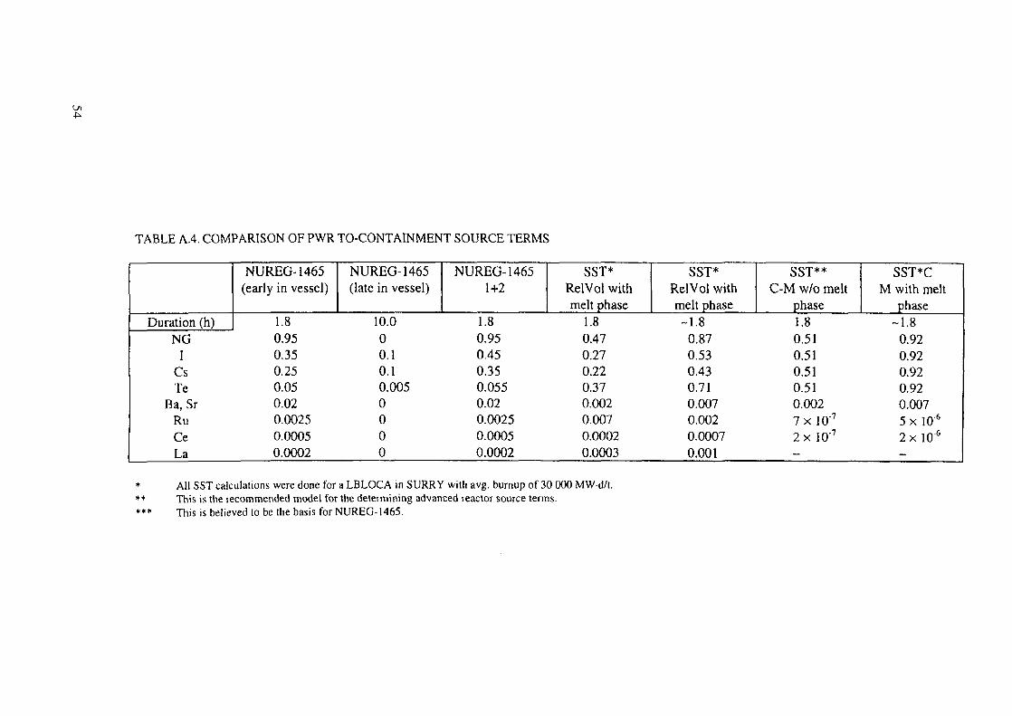
t
TABLE A.4. COMPARISON OF PWR TO-CONTAINMENT SOURCE TERMS
Duration (h)NG
ICsTe
Ba, SrRuCeLa
NUREG-1465(early in vessel)
1.80.950.350.250.050.020.00250.00050.0002
NUREG-1465(late in vessel)
10.000.10.10.0050000
NUREG-14651+2
1.80.950.450.350.0550.020.00250.00050.0002
SST*RelVol withmelt phase
1.80.470.270.220.370.0020.0070.00020.0003
SST*RelVol withmelt phase-1.8
0.870.530.430.710.0070.0020.00070.001
SST**C-M w/o melt
phase1.80.510.510.510.510.0027 x 10"7
2 x 10'7
-
SST*CM with melt
phase-1.8
0.920.920.920.920.0075 x 10'6
2 x 10"6
-
* All SST calculations were done for a LBLOCA in SURRY with avg. burnup of 30 000 MWd/t.•* This is the recommended model for the determining advanced reactor source terms.*** This is believed to be the basis for NUREG-1465.

assumes adiabatic heat up. If there are significant heat losses to the steam, then the heat-uprate could be slower. Slower heat-up rates result in greater fission product release becauselonger times are spent at any given temperature during the transient. In addition, the results ofrecent experimental programmes need to be assessed before release from molten systemswithout sparging can be discounted.
Overall, the results of SST using the generalized thermal transient and the Kress/BoothRelVol fission product release model appear to be reasonable and proper for use to developplant specific design basis source terms for future nuclear power plants.
55
REFERENCES
[A.I] HASKINS, E., Whole core decay heat power, private communication (1986).[A.2] WOOTON, R.O., AVCI, H.I., MARCH (Meltdown Accident Response Characteristics)
Code Description and Users Manual, Rep. NUREG/CR-1711, Battelle Columbus Labs,OH (1980).
[A.3] REST, J., An improved model for fission product behaviour in nuclear fuel undernormal and accident conditions, J. Nuclear Materials 120 (1994) 195.
[A.4] KRESS, T.S., LORENZ, R.A., OSBORNE, M.F., NAKAMURA, T., "Correlation ofrecent fission product release data", Proceedings of the ICHMT International Seminar,Dubrovnik, 1987, (ROGERS, J., Ed.), Hemisphere Publishing, New York (1989) 47-255.
[A.5] BOOTH, A.H., RYMER, G.T., Determination of the Diffusion Constant of FissionXenon in UOT Crystals and Sintered Compounds, Atomic Energy of Canada Limited(AECL), Rep. CRDC-720, Chalk River Laboratories, Chalk River, Ontario (1958).
[A.6] OSBORNE, M.F., LORENZ, R.A., ORNL Studies of fission product release underLWR severe accident conditions, Nuclear Safety 33 3 (1992).
[A.7] LORENZ, R.A., "The vaporization of structural material in severe accidents",Proceedings of the International Meeting on Thermal Nuclear Reactor Safety, Rep.NUREG/CR-0027, Vol. 2, Oak Ridge National Lab., TN (1982).
[A.8] GEESEKE, J.A., CYBULSKIS, P., DENNING, R.S., KUHLMAN, M.R., LEE, K.W.,Radionuclide Release under Specific LWR Accident Conditions, Rep. BMI-2104,Vol. 5, Battelle Columbus Labs, OH (1984).
56

Annex
CODE LISTINGS AND CALCULATION RESULTS
r t
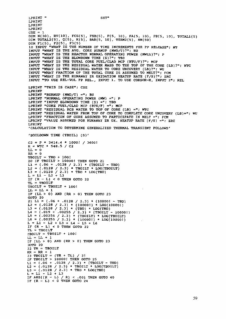
LPRINT " SST"LPRINTLPRINTLPRINTCSE = 1DIM N(30), RV(10), FCS(5), FSB(5), F(5, 10), FA(5, 10), FB(5, 10), TOTAL1(5)DIM TOTAL2(5), Q(5), K(5), BAR(5, 10), TERM2(5), NN(50)DIM Fl(5), F2(5), F3(5)10 INPUT "WHAT IS THE NUMBER OF TIME INCREMENTS FOR FP RELEASE"; NTINPUT "WHAT IS THE AVG. CORE BURNUP (MWD/T)?"; BUINPUT "WHAT IS THE REACTOR NORMAL OPERATING POWER (MWth)?"; PINPUT "WHAT IS THE BLOWDOWN TIME (S)?"; TBDINPUT "WHAT IS THE TOTAL CORE FUEL/CLAD MCP (BTU/F)?"; MCPINPUT "WHAT IS THE RESIDUAL WATER MASS TO THE TOP OF THE CORE (LB)?"; WTCINPUT "WHAT IS THE RESIDUAL WATER TO CORE UNCOVERY (LB)?"; WUINPUT "WHAT FRACTION OF THE TOTAL CORE IS ASSUMED TO MELT?"; FCMINPUT "WHAT IS THE RUNAWAY ZR OXIDATION HEATUP RATE (F/S)?"; ZRCINPUT "TO USE REL-VOL FP REL. , INPUT 1. TO USE CORSOR-M, INPUT 2"; REL
LPRINT "THIS IS CASE"; CSELPRINTLPRINT "BURNUP (MWD/T) ="; BULPRINT "NORMAL OPERATING POWER (MW) ="; PLPRINT "INPUT BLOWDOWN TIME (S) ="; TBDLPRINT "CORE FUEL/CLAD MCP (BTU/F) ="; MCPLPRINT "RESIDUAL RCS WATER TO TOP OF CORE (LB) =••; WTCLPRINT "RESIDUAL WATER FROM TOP OF CORE TO COMPLETE CORE UNCOVERY (LB)="; WULPRINT "FRACTION OF CORE ASSUMED TO PARTICIPATE IN MELT ="; FCMLPRINT "VALUE ASSUMED FOR RUNAWAY ZR OX. HEATUP RATE (F/S) ="; ZRCLPRINT'CALCULATION TO DETERMINE GENERALIZED THERMAL TRANSIENT FOLLOWS'
'BOILDOWN TIME (TBOIL) (S)'
C2 = P * 3414.4 * lOOOi / 3600!R = WTC * 548.5 / C2LL = 0RR = 0TBOILT = TBD +100!20 IF TBOILT > 10000! THEN GOTO 21LI = (.06 + .0128 / 2.3) * (TBOILT - TBD)L2 = (.0128 / 2.3) * TBOILT * LOG(TBOILT)L3 = (.0128 / 2.3) * TBD * LOG(TBD)L = LI - L2 + L3IF (R - L) < 0 THEN GOTO 22TL = TBOILTTBOILT = TBOILT + 100!LL = LL + 1IF (LL > 0) AND (RR > 0) THEN GOTO 23GOTO 2021 LI = (.06 + .0128 / 2.3) * (10000! - TBD)L2 = (.0128 / 2.3) * (10000!) * LOG(10000!)L3 = (.0128 / 2.3) * (TBD) * LOG(TBD)L4 = (.019 + .00255 / 2.3) * (TBOILT - 10000!)L5 = (.00255 / 2.3) * (TBOILT) * LOG(TBOILT)L6 = (.00255 / 2.3) * (10000!) * LOG(10000!)L = LI - L2 + L3 + L4 - L5 + L6IF (R - L) < 0 THEN GOTO 22TL = TBOILTTBOILT = TBOILT + 100!LL = LL + 1IF (LL > 0) AND (RR > 0) THEN GOTO 233OTO 2022 TR = TBOILTRR = RR + 123 TBOILT = (TR + TL) / 2!IF TBOILT > 10000! THEN GOTO 25LI = (.06 + .0128 / 2.3) * (TBOILT - TBD)L2 = (.0128 / 2.3) * TBOILT * LOG(TBOILT)L3 = (.0128 / 2.3) * TBD * LOG(TBD)L = LI - L2 + L3IF ABS((R - L) / R) < .001 THEN GOTO 40IF (R - L) < 0 THEN GOTO 24
59
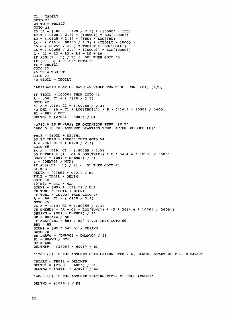
TL = TBOILTGOTO 2324 TR = TBOILTGOTO 2325 LI = (.06 + .0128 / 2.3) * (10000! - TBD)L2 = (.0128 / 2.3) * (10000!) * LOG(10000!)L3 = (.0128 / 2.3) * (TBD) * LOG(TBD)L4 = (.019 + .00255 / 2.3) * (TBOILT - 10000!)L5 = (.00255 / 2.3) * TBOILT * LOG(TBOILT)L6 = (.00255 / 2.3) * (10000!) * LOG(10000!)L = LI - L2 + L3 + L4 - L5 + L6IF ABS((R - L) / R) < .001 THEN GOTO 40IF (R - L) < 0 THEN GOTO 26TL = TBOILTGOTO 2326 TR = TBOILTGOTO 2340 TBOIL = TBOILT
'ADIABATIC HEAT-UP RATE AVERAGED FOR WHOLE CORE (Bl) (F/S)'
IF TBOIL > 10000! THEN GOTO 41A = .06: Cl = (.0128 / 2.3)GOTO 4241 A = .019: Cl = (.00255 / 2.3)42 DH1 = (A - Cl * LOG(TBOIL)) * P * 3414.4 * 1000! / 3600!Bl = DH1 / MCPDELTM1 = (2780! - 600!) / Bl
'2780.0 IS RUNAWAY ZR OXIDATION TEMP. IN F''600.0 IS THE ASSUMED STARTING TEMP. AFTER BOILOFF (F)'
TM1E = TBOIL + DELTM150 IF TM1E > 10000! THEN GOTO 54A = .06: Cl = (.0128 / 2.3)GOTO 5554 A = .019: Cl = (.00255 / 2.3)55 DHEND1 = (A - Cl * LOG(TMIE)) * P * 3414.4 * 1000! / 3600!DHAVG1 = (DH1 + DHEND1) / 2!B = (DHAVG1 / MCP)IF ABS((B1 - B) / B) < .01 THEN GOTO 60Bl = BDELTM = (2780! - 600!) / BlTM1E = TBOIL + DELTMGOTO 5060 BB1 = DH1 / MCPDTUN1 = (WU) * (548.5) / DH170 TUN1 = TBOIL + DTUN1IF TUN1 > 10000! THEN GOTO 74A = .06: Cl = ( .0128 / 2.3)GOTO 7574 A = .019: Cl = (.00255 / 2.3)75 DHEND2 = (A - Cl * LOG(TUNl)) * (P * 3414.4 * 1000! / 3600!)DH2AVG = (DH1 + DHEND2) / 2!BB = DH2AVG / MCPIF ABS((BB1 - BB) / BB) < .01 THEN GOTO 80BB1 = BBDTUN1 = (WU * 545.5) / DH2AVGGOTO 7080 DHAVG = (DHAVG1 + DH2AVG) / 2!Bl = DHAVG / MCPB2 = ZRCDELTMFP = (1700! - 600!) / Bl
'1700 (F) IS THE ASSUMED CLAD FAILURE TEMP. &, HENCE, START OF F.P. RELEASE'
TSTART = TBOIL + DELTMFPDELTM1 = (2780! - 600!) / BlDELTM2 = (4868! - 2780!) / B2
'4868 (F) IS THE ASSUMED MELTING TEMP. OF FUEL (ZR02)'
DELTM3 = (1029!) / B2
60
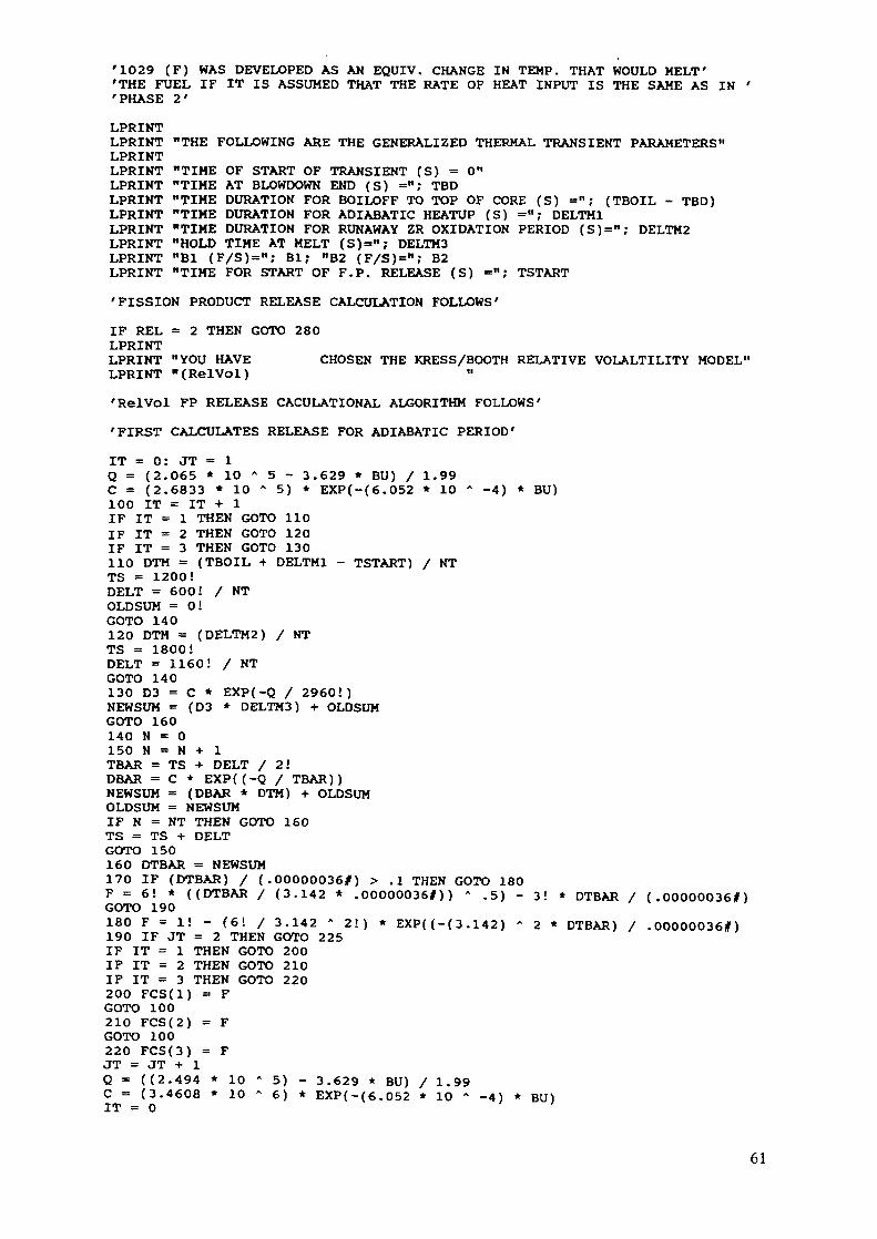
'1029 (F) WAS DEVELOPED AS AH EQUIV. CHANGE IN TEMP. THAT WOULD MELT''THE FUEL IF IT IS ASSUMED THAT THE RATE OF HEAT INPUT IS THE SAME AS IN ''PHASE 2'
LPRINTLPRINT "THE FOLLOWING ARE THE GENERALIZED THERMAL TRANSIENT PARAMETERS"LPRINTLPRINT "TIME OF START OF TRANSIENT (S) = 0"LPRINT "TIME AT BLOWDOWN END (S) ="; TBDLPRINT "TIME DURATION FOR BOILOFF TO TOP OF CORE (S) = "; (TBOIL - TBD)LPRINT "TIME DURATION FOR ADIABATIC HEATUP (S) ="; DELTM1LPRINT "TIME DURATION FOR RUNAWAY ZR OXIDATION PERIOD (S)="; DELTM2LPRINT "HOLD TIME AT MELT (S)="; DELTH3LPRINT "Bl (F/S)=n; Bl; "B2 (F/S)="; B2LPRINT "TIME FOR START OF F.P. RELEASE (S) ="; TSTART
'FISSION PRODUCT RELEASE CALCULATION FOLLOWS'
IF REL = 2 THEN GOTO 280LPRINTLPRINT "YOU HAVE CHOSEN THE KRESS/BOOTH RELATIVE VOLALTILITY MODEL"
LPRINT "(RelVol) "
'RelVol FP RELEASE CACULATIONAL ALGORITHM FOLLOWS'
'FIRST CALCULATES RELEASE FOR ADIABATIC PERIOD'
IT = 0: JT = 1Q = (2.065 * 10 A 5 - 3.629 * BU) / 1.99C = (2.6833 * 10 * 5) * EXP(-(6.052 * 10 A -4) * BU)100 IT = IT + 1IF IT = 1 THEN GOTO 110IF IT = 2 THEN GOTO 120IF IT = 3 THEN GOTO 130110 DTM = (TBOIL + DELTM1 - TSTART) / NTTS = 1200!DELT = 600! / NTOLDSUM = 0!GOTO 140120 DTM = (DELTM2) / NTTS = 1800!DELT = 1160! / NTGOTO 140130 D3 = C * EXP(-Q / 2960!)NEWSUM = (D3 * DELTM3) + OLDSUMGOTO 160140 N = 0150 N = N + 1TBAR = TS + DELT / 2!DBAR = C * EXP((-Q / TBAR))NEWSUM = (DBAR * DTM) + OLDSUMOLDSUM = NEWSUMIF N = NT THEN GOTO 160TS = TS + DELTGOTO 150160 DTBAR = NEWSUM170 IF (DTBAR) / (.00000036#) > .1 THEN GOTO 180F = 6! * ((DTBAR / (3.142 * .O0000036#)) » .5) - 3! * DTBAR / (.O0000036|MGOTO 190180 F = 1! - (6! / 3.142 * 2!) * EXP((-(3.142) " 2 * DTBAR) / .000000361)190 IF JT = 2 THEN GOTO 225IF IT = 1 THEN GOTO 200IF IT = 2 THEN GOTO 210IF IT = 3 THEN GOTO 220200 FCS(l) = FGOTO 100210 FCS(2) = FGOTO 100220 FCS(3) = FJT = JT + 1Q = ((2.494 * 10 " 5) - 3.629 * BU) / 1.99C = (3.4608 * 10 * 6) * EXP(-(6.052 * 10 A -A) * BU)IT = 0
61
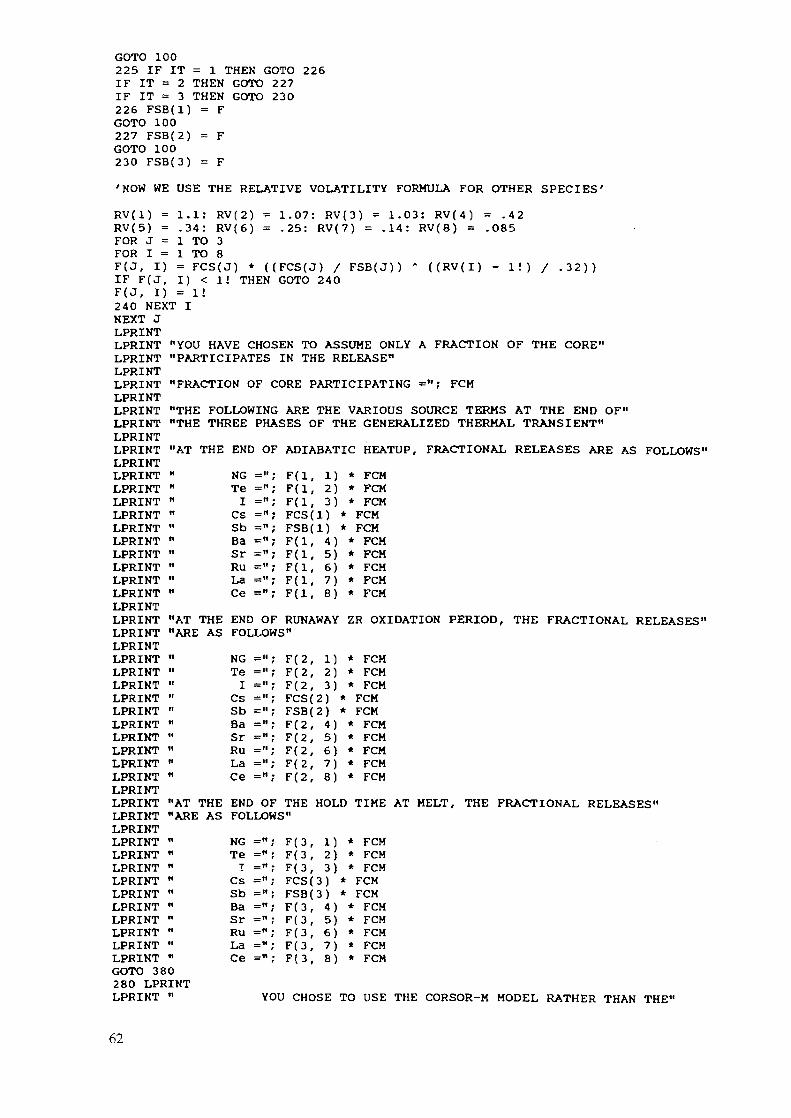
GOTO 100225 IF IT = 1 THEN GOTO 226IF IT = 2 THEN GOTO 227IF IT = 3 THEN GOTO 230226 FSB(l) = FGOTO 100227 FSB(2) = FGOTO 100230 FSB(3) = F
'NOW WE USE THE RELATIVE VOLATILITY FORMULA FOR OTHER SPECIES'
"YOU HAVE CHOSEN TO ASSUME ONLY A FRACTION OF THE CORE""PARTICIPATES IN THE RELEASE"
"FRACTION OF CORE PARTICIPATING FCM
NGTeI
CSSbBaSrRuLaCe
= «=«=»— n
F(l, 1) * FCMF(l, 2) * FCMF(l, 3) * FCMFCS(l) * FCMFSB(l) * FCM
4)5)6)7)8)
FCMFCMFCMFCMFCM
RV(1) = 1.1: RV(2) = 1.07: RV(3) = 1.03: RV(4) = .42RV(5) = .34: RV(6) = .25: RV(7) = .14: RV(8) = .085FOR J = 1 TO 3FOR I = 1 TO 8F(J, I) = FCS(J) * ((FCS(J) / FSB(J)) " ((RV(I) - 1!) / .32))IF F(J, I) < 1! THEN GOTO 240F(J, I) = 1!240 NEXT INEXT JLPRINTLPRINTLPRINTLPRINTLPRINTLPRINTLPRINT "THE FOLLOWING ARE THE VARIOUS SOURCE TERMS AT THE END OF"LPRINT "THE THREE PHASES OF THE GENERALIZED THERMAL TRANSIENT"LPRINTLPRINT "AT THE END OF ADIABATIC HEATUP, FRACTIONAL RELEASES ARE AS FOLLOWS"LPRINTLPRINTLPRINTLPRINTLPRINTLPRINTLPRINTLPRINTLPRINTLPRINTLPRINTLPRINTLPRINTLPRINTLPRINTLPRINTLPRINTLPRINTLPRINTLPRINTLPRINTLPRINTLPRINTLPRINTLPRINTLPRINTLPRINT "AT THE END OF THE HOLD TIME AT MELT,LPRINT "ARE AS FOLLOWS"LPRINTLPRINT " NGLPRINT " TeLPRINT " ILPRINT " CsLPRINT " SbLPRINT " BaLPRINT " SrLPRINT " RuLPRINT " LaLPRINT " CeGOTO 380280 LPRINTLPRINT "
"AT THE END OF RUNAWAY ZR OXIDATION PERIOD, THE FRACTIONAL RELEASES1
"ARE AS FOLLOWS"
NGTeI
CsSbBaSrRuLaCe
— 11
— II
— 11
— II
= "
— II
_n
— ii
— H
F(2, 1) * FCMF(2, 2) * FCMF(2, 3) * FCMFCS(2) * FCMFSB(2) * FCMF(2, 4)
5)6)7)8)
F(2,F(2,F(2,F(2,
FCMFCMFCMFCMFCM
THE FRACTIONAL RELEASES"
_rt
= »
— II
F(3, 1) * FCMF(3, 2) * FCMF(3, 3) * FCMFCS(3) * FCMFSB(3) * FCMF(3,F(3,F(3,F{3,F(3,
4)5)6)7)8)
FCMFCMFCMFCHFCM
YOU CHOSE TO USE THE CORSOR-M MODEL RATHER THAN THE"
62
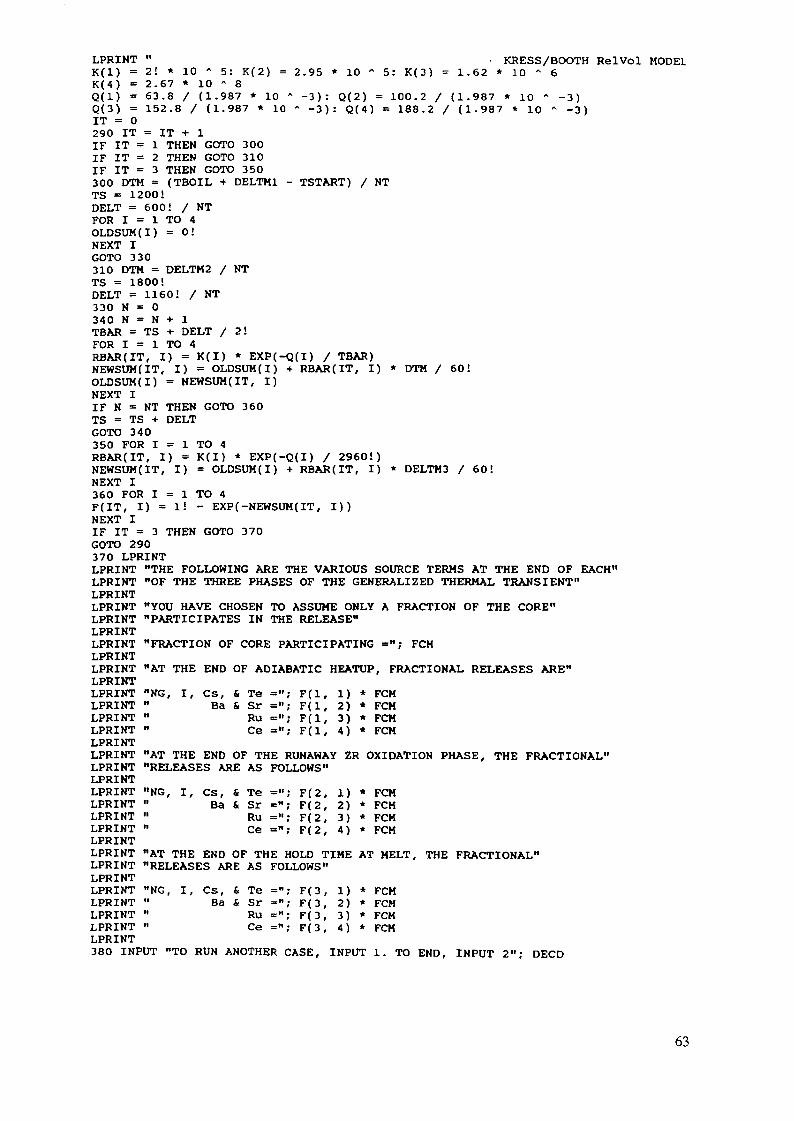
LPRINT " - KRESS/BOOTH RelVol MODE1K(l) = 21 * 10 * 5: K(2) = 2.95 * 10 A 5: K( 3) = 1.62 * 10 " 6K(4) = 2.67 * 10 A 8Q(l) = 63.8 / (1.987 * 10 A -3): Q(2) = 100.2 / (1.987 • 10 " -3)Q(3) = 152.8 / (1.987 * 10 * - 3 ) : Q(4) = 188.2 / (1.987 * 10 A -3)IT = 0290 IT = IT + 1IF IT = 1 THEN GOTO 300IF IT = 2 THEN GOTO 310IF IT = 3 THEN GOTO 350300 DTM = (TBOIL + DELTM1 - TSTART) / NTTS = 1200!DELT = 600! / NTFOR I = 1 TO 4OLDSUM(I) = 0!NEXT IGOTO 330310 DTM = DELTM2 / NTTS = 1800!DELT = 1160! / NT330 N = 0340 N = N +• 1TBAR = TS + DELT / 2!FOR I = 1 TO 4RBAR(IT, I) = K(I) * EXP(-Q(I) / TBAR)NEWSUM(IT, I) = OLDSUM(I) + RBAR(IT, I) * DTM / 60!OLDSUM(I) = NEWSUM(IT, I)NEXT IIF N = NT THEN GOTO 360TS = TS + DELTGOTO 340350 FOR I = 1 TO 4RBAR(IT, I) = K(I) * EXP(-Q(I) / 2960!)NEWSUM(IT, I) = OLDSUM(I) + RBAR(IT, I) * DELTM3 / 60!NEXT I360 FOR I = 1 TO 4F(IT, I) = 1! - EXP(-NEWSUM(IT, I))NEXT IIF IT = 3 THEN GOTO 370GOTO 290370 LPRINTLPRINT "THE FOLLOWING ARE THE VARIOUS SOURCE TERMS AT THE END OF EACH"LPRINT "OF THE THREE PHASES OF THE GENERALIZED THERMAL TRANSIENT"LPRINTLPRINT "YOU HAVE CHOSEN TO ASSUME ONLY A FRACTION OF THE CORE"LPRINT "PARTICIPATES IN THE RELEASE"LPRINTLPRINT "FRACTION OF CORE PARTICIPATING ="; FCMLPRINTLPRINT "AT THE END OF ADIABATIC HEATUP, FRACTIONAL RELEASES ARE"LPRINTLPRINT "NG, ILPRINT "LPRINT "LPRINT "LPRINTLPRINT "AT THE END OF THE RUNAWAY ZR OXIDATION PHASE, THE FRACTIONAL"LPRINT "RELEASES ARE AS FOLLOWS"LPRINTLPRINT "NG, ILPRINT "LPRINT "LPRINT "LPRINTLPRINT "AT THE END OF THE HOLD TIME AT MELT, THE FRACTIONAL"LPRINT "RELEASES ARE AS FOLLOWS"LPRINTLPRINT "NG, I, Cs, & Te ="; F(3, 1) * FCMLPRINT " Ba & Sr ="; F(3, 2) * FCMLPRINT " Ru ="; F(3, 3) * FCMLPRINT " Ce ="; F(3, 4) * FCMLPRINT380 INPUT "TO RUN ANOTHER CASE, INPUT 1. TO END, INPUT 2"; DECD
s, &Ba &
TeSrRuCe
="; F(="; F(="; F(
l, i)1, 2)1, 3)1- 4)
**•*
FCMFCMFCMFCM
s, &Ba &
Te =";Sr =";Ru =";Ce =";
F(2,F(2,F(2,F(2,
1)2)3)4)
* FCM* FCM* FCM* FCM
63
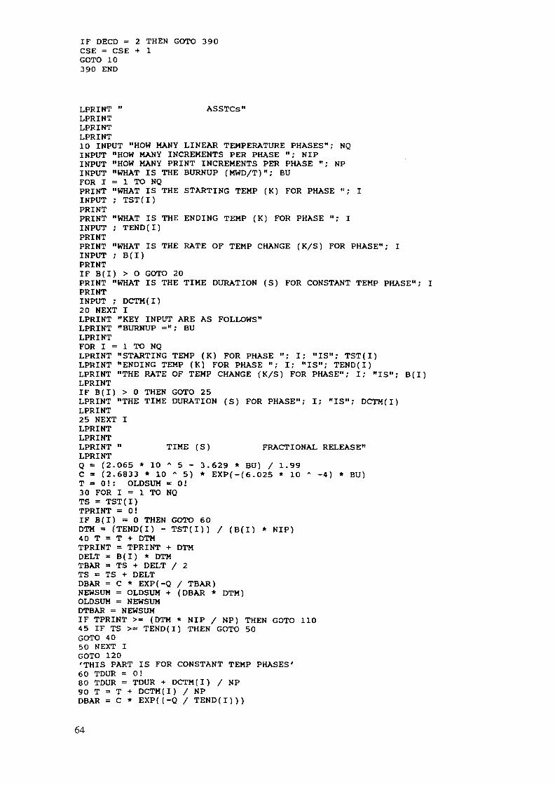
IF DECD = 2 THEN GOTO 390CSE = CSE + 1GOTO 10390 END
LPRINT " ASSTCs"LPRINTLPRINTLPRINT10 INPUT "HOW MANY LINEAR TEMPERATURE PHASES"; NQINPUT "HOW MANY INCREMENTS PER PHASE "; NIPINPUT "HOW MANY PRINT INCREMENTS PER PHASE "; NPINPUT "WHAT IS THE BURNUP (MWD/T)"; BUFOR I = 1 TO NQPRINT "WHAT IS THE STARTING TEMP (K) FOR PHASE "; IINPUT ; TST(I)PRINTPRINT "WHAT IS THE ENDING TEMP (K) FOR PHASE "; IINPUT ; TEND(I)PRINTPRINT "WHAT IS THE RATE OF TEMP CHANGE (K/S) FOR PHASE"; IINPUT ; B(I)PRINTIF B(I) > O GOTO 20PRINT "WHAT IS THE TIME DURATION (S) FOR CONSTANT TEMP PHASE"; IPRINTINPUT ; DCTM{I)20 NEXT ILPRINT "KEY INPUT ARE AS FOLLOWS"LPRINT "BURNUP ="; BULPRINTFOR I = 1 TO NQLPRINT "STARTING TEMP (K) FOR PHASE "; I; "IS"; TST(I)LPRINT "ENDING TEMP (K) FOR PHASE "; I; "IS"; TEND(I)LPRINT "THE RATE OF TEMP CHANGE (K/S) FOR PHASE"; I; "IS"; B(I)LPRINTIF B(I) > 0 THEN GOTO 25LPRINT "THE TIME DURATION (S) FOR PHASE"; I; "IS"; DCTM(I)LPRINT25 NEXT ILPRINTLPRINTLPRINT " TIME (S) FRACTIONAL RELEASE"LPRINTQ = (2.065 * 10 A 5 - 3.629 * BU) / 1.99C = (2.6833 * 10 A 5) • EXP(-(6.025 * 10 A -4) * BU)T = 0!: OLDSUM = 0!30 FOR I = 1 TO NQTS = TST(I)TPRINT = 0!IF B(I) = 0 THEN GOTO 60DTM = (TEND(I) - TST(I)) / (B(I) * NIP)40 T = T + DTMTPRINT = TPRINT + DTMDELT = B(I) * DTMTBAR = TS + DELT / 2TS = TS + DELTDBAR = C * EXP(-Q / TBAR)NEWSUM = OLDSUM + (DBAR * DTM)OLDSUM = NEWSUMDTBAR = NEWSUMIF TPRINT >= (DTM * NIP / NP) THEN GOTO 1104 5 IF TS >= TEND(I) THEN GOTO 50GOTO 4 050 NEXT IGOTO 120'THIS PART IS FOR CONSTANT TEMP PHASES'60 TDUR = 0!80 TDUR = TDUR + DCTM(I) / NP90 T = T + DCTM(I) / NPDBAR = C * EXP((-Q / TEND(I)))
64
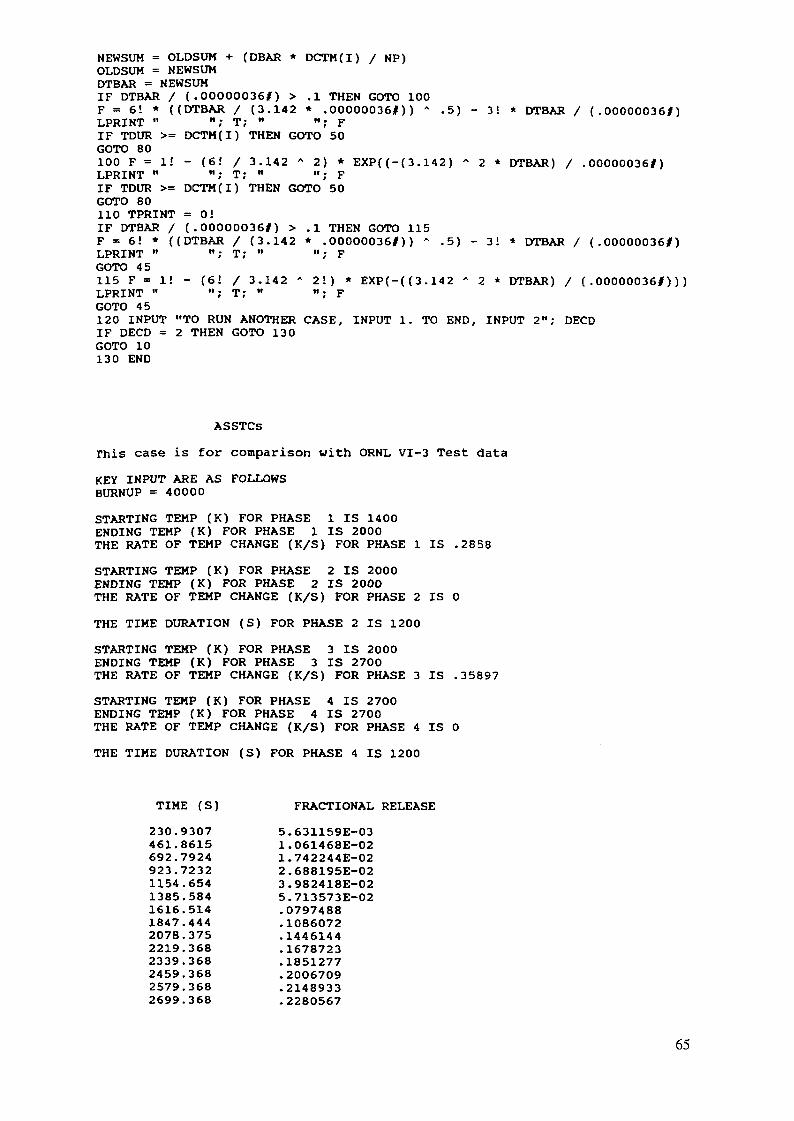
NEWSUM = OLDSUM + (DBAR * DCTM(I) / NP)OLDSUM = NEWSUMDTBAR = NEWSUMIF DTBAR / (.000000361) > .1 THEN GOTO 100F = 6! * ((DTBAR / (3.142 * .000000361)) * .5) - 3! * DTBAR / (.000000361)LPRINT " "; T; " "; FIF TDUR >= DCTM(I) THEN GOTO 50GOTO 80100 F = 1! - (6! / 3.142 * 2) * EXP((-(3.142) - 2 * DTBAR) / .00000036#)LPRINT " "; T; " "; FIF TDUR >= DCTM(I) THEN GOTO 50GOTO 80110 TPRINT = 0!IF DTBAR / (.000000361) > .1 THEN GOTO 115F = 6! * ((DTBAR / (3.142 * .000000361)) A .5) - 3! * DTBAR / (.00000036#)LPRINT " "; T; " "; FGOTO 45115 F = 1! - (6! / 3.142 * 2!) * EXP(-((3.142 - 2 * DTBAR) / (.000000361)))LPRINT " "; T; " "; FGOTO 45120 INPUT "TO RUN ANOTHER CASE, INPUT 1. TO END, INPUT 2"; DECDIF DECD = 2 THEN GOTO 130GOTO 10130 END
ASSTCs
This case is for comparison with ORNL VI-3 Test data
KEY INPUT ARE AS FOLLOWSBURNUP = 40000
STARTING TEMP (K) FOR PHASE 1 IS 1400ENDING TEMP (K) FOR PHASE 1 IS 2000THE RATE OF TEMP CHANGE (K/S) FOR PHASE 1 IS .2858
STARTING TEMP (K) FOR PHASE 2 IS 2000ENDING TEMP (K) FOR PHASE 2 IS 2000THE RATE OF TEMP CHANGE (K/S) FOR PHASE 2 IS 0
THE TIME DURATION (S) FOR PHASE 2 IS 1200
STARTING TEMP (K) FOR PHASE 3 IS 2000ENDING TEMP (K) FOR PHASE 3 IS 2700THE RATE OF TEMP CHANGE (K/S) FOR PHASE 3 IS .35897
STARTING TEMP (K) FOR PHASE 4 IS 2700ENDING TEMP (K) FOR PHASE 4 IS 2700THE RATE OF TEMP CHANGE (K/S) FOR PHASE 4 IS 0
THE TIME DURATION (S) FOR PHASE 4 IS 1200
TIME (S)
230.9307461.8615692.7924923.72321154.6541385.5841616.5141847.4442078.3752219.3682339.3682459.3682579.3682699.368
FRACTIONAL RELEASE
5.631159E-031.061468E-021.742244E-022.688195E-023.982418E-025.713573E-02.0797488.1086072.1446144.1678723.1851277.2006709.2148933.2280567
65
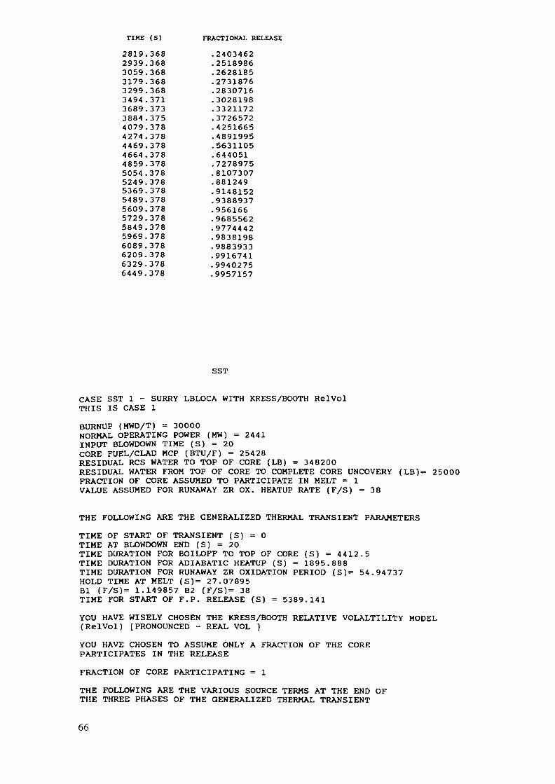
TIKE (S) FRACTIONAL RELEASE
2819.368 .24034622939.368 .25189863059.368 .26281853179.368 .27318763299.368 .28307163494.371 .30281983689.373 .33211723884.375 .37265724079.378 .42516654274.378 .48919954469.378 .56311054664.378 .6440514859.378 .72789755054.378 .81073075249.378 .8812495369.378 .91481525489.378 .93889375609.378 .9561665729.378 .96855625849.378 .97744425969.378 .98381986089.378 .98839336209.378 .99167416329.378 .99402756449.378 .9957157
SST
CASE SST 1 - SURRY LBLOCA WITH KRESS/BOOTH RelVolTHIS IS CASE 1
BURNUP (MWD/T) = 30000NORMAL OPERATING POWER (MW) = 2441INPUT BLOWDOWN TIME (S) = 20CORE FUEL/CLAD MCP (BTU/F) = 254 28RESIDUAL RCS WATER TO TOP OF CORE (LB) = 348200RESIDUAL WATER FROM TOP OF CORE TO COMPLETE CORE UNCOVERY (LB)= 25000FRACTION OF CORE ASSUMED TO PARTICIPATE IN MELT = 1VALUE ASSUMED FOR RUNAWAY ZR OX. HEATUP RATE (F/S) = 38
THE FOLLOWING ARE THE GENERALIZED THERMAL TRANSIENT PARAMETERS
TIME OF START OF TRANSIENT (S) = 0TIME AT BLOWDOWN END (S) = 20TIME DURATION FOR BOILOFF TO TOP OF CORE (S) = 4412.5TIME DURATION FOR ADIABATIC HEATUP (S) = 1895.888TIME DURATION FOR RUNAWAY ZR OXIDATION PERIOD (S)= 54.94 737HOLD TIME AT MELT (S)= 27.07895Bl (F/S)= 1.149857 B2 (F/S)= 38TIME FOR START OF F.P. RELEASE (S) = 5389.141
YOU HAVE WISELY CHOSEN THE KRESS/BOOTH RELATIVE VOLALTILITY MODEL(RelVol) [PRONOUNCED - REAL VOL ]
YOU HAVE CHOSEN TO ASSUME ONLY A FRACTION OF THE COREPARTICIPATES IN THE RELEASE
FRACTION OF CORE PARTICIPATING = 1
THE FOLLOWING ARE THE VARIOUS SOURCE TERMS AT THE END OFTHE THREE PHASES OF THE GENERALIZED THERMAL TRANSIENT
66
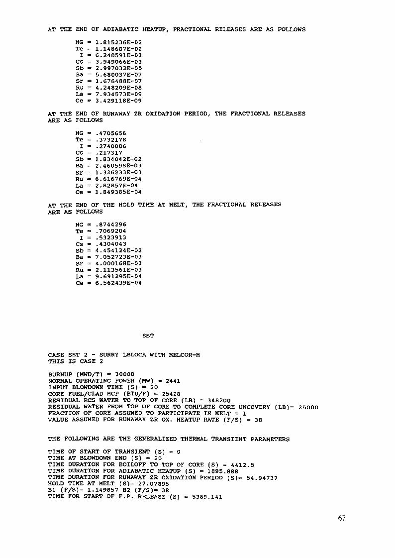
AT THE END OF ADIABATIC HEATUP, FRACTIONAL RELEASES ARE AS FOLLOWS
NG =Te =I =
Cs =Sb =Ba =Sr =Ru =La =Ce =
1.815236E-021.148687E-026.240591E-033.949066E-032.997032E-055.680037E-071.676488E-074.248209E-087.934573E-093.429118E-09
AT THE END OF RUNAWAY ZR OXIDATION PERIOD, THE FRACTIONAL RELEASESARE AS FOLLOWS
NG =Te =I =
Cs =Sb =Ba =Sr =Ru =La =Ce =
.4705656
.3732178
.2740006
.2173171.834042E-022.460598E-031.326233E-036.616769E-042.82857E-041.849385E-04
AT THE END OF THE HOLD TIME AT MELT, THE FRACTIONAL RELEASESARE AS FOLLOWS
NG =Te =I =
CS =Sb =Ba =Sr =Ru =La =Ce =
.8744296
.7069204
.5323913
.43040434.454124E-027.052723E-034.000168E-032.113561E-039.691295E-046.562439E-04
SST
CASE SST 2 - SURRY LBLOCA WITH MELCOR-MTHIS IS CASE 2
BURNUP (MWD/T) = 30000NORMAL OPERATING POWER (MW) = 2441INPUT BLOWDOWN TIME (S) = 20CORE FUEL/CLAD MCP (BTU/F) = 25428RESIDUAL RCS WATER TO TOP OF CORE (LB) = 348200RESIDUAL WATER FROM TOP OF CORE TO COMPLETE CORE UNCOVERY (LB)= 25000FRACTION OF CORE ASSUMED TO PARTICIPATE IN MELT = 1VALUE ASSUMED FOR RUNAWAY ZR OX. HEATUP RATE (F/S) = 3 8
THE FOLLOWING ARE THE GENERALIZED THERMAL TRANSIENT PARAMETERS
TIME OF START OF TRANSIENT (S) = 0TIME AT BLOWDOWN END (S) = 20TIME DURATION FOR BOILOFF TO TOP OF CORE (S) = 4412.5TIME DURATION FOR ADIABATIC HEATUP (S) = 1895.888TIME DURATION FOR RUNAWAY ZR OXIDATION PERIOD (S)= 54.94737HOLD TIME AT MELT (S)= 27.07895Bl (F/S)= 1.149857 B2 (F/S)= 38TIME FOR START OF F.P. RELEASE (S) = 5389.141
67
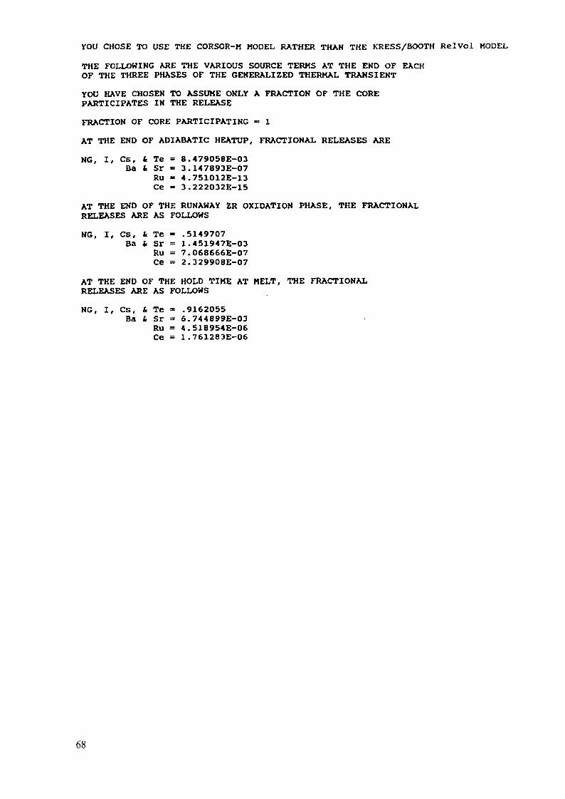
CHOSE TO USE THE CORSOR-H MODEL RATHER THAN THE KRESS/BOOTH RelVol MODEL
THE FOLLOWING ARE THE VARIOUS SOURCE TERMS AT THE END OF EACHOF THE THREE PHASES OF THE GENERALIZED THERMAL TRANSIENT
YOU HAVE CHOSEN TO ASSUME ONLY A FRACTION OF THE COREPARTICIPATES IN THE RELEASE
FRACTION OF CORE PARTICIPATING " 1
AT THE END OF ADIABATIC HEATUP, FRACTIONAL RELEASES ARE
NG, I, Cs, t Te= 8.479058E-03Ba i Sr = 3.147893E-07
Ru « 4.751012E-13Ce - 3.222032E-15
AT THE END OF THE RUNAWAY ZR OXIDATION PHASE, THE FRACTIONALRELEASES ARE AS FOLLOWS
NG, I, CS, £ Te - .5149707Ba & Sr = 1.451947E-03
Ru = 7.068666E-07Ce = 2.329908E-07
AT THE END OF THE HOLD TIME AT MELT, THE FRACTIONALRELEASES ARE AS FOLLOWS
NG, I, Cs, t Te = .9162055Ba 6 Sr = 6.744899E-03
Ru = 4.518954E-06Ce = 1.761283E-06
68