A Simple and Effective Strategy to Prevent Power Transformer ...
14
201 American Scientific Research Journal for Engineering, Technology, and Sciences (ASRJETS) ISSN (Print) 2313-4410, ISSN (Online) 2313-4402 © Global Society of Scientific Research and Researchers http://asrjetsjournal.org/ A Simple and Effective Strategy to Prevent Power Transformer Overloading Ahmed Bin-Halabi a *, Adnan Nouh b , Mohammad Abouelela c a,b,c Department of Electrical Engineering, King Saud University, Riyadh 11421, Saudi Arabia a Email: [email protected] b Email: [email protected] c Email: [email protected] Abstract This paper presents a novel strategy to prevent overloading of distribution transformers. The strategy is based on a developed algorithm for home energy management (HEM) system. The algorithm is mainly aimed to prevent the complete power outage of an area that may occur due to transformer overloading. The task can be accomplished by a supervised reduction in power consumption of the customers supplied through the overloaded transformer without tripping the transformer, since the complete disconnection of service is considered undesirable by the customers. The proposed algorithm is intended to minimize the number of switched-off appliances to lessen their impact on the customer's comfort level. The strategy is simple and effective in terms of cost and performance. MATLAB/Simulink was used to simulate the system and to validate the proposed strategy. The simulation results show the effectiveness of the strategy to avoid transformer overloading and thus preventing power outage. Keywords: Distribution transformer protection; HEM system; Interruptible appliances; Overloading prevention; Power outage. 1. Introduction One of the most challenging problems that power distribution systems are facing is the overloading of distribution transformers, especially in high population density areas, which results in a complete power outage of the areas supplied through the overloaded transformers. ------------------------------------------------------------------------ * Corresponding author.
-
Upload
khangminh22 -
Category
Documents
-
view
3 -
download
0
Transcript of A Simple and Effective Strategy to Prevent Power Transformer ...
201
American Scientific Research Journal for Engineering, Technology, and Sciences (ASRJETS) ISSN (Print) 2313-4410, ISSN (Online) 2313-4402
© Global Society of Scientific Research and Researchers http://asrjetsjournal.org/
A Simple and Effective Strategy to Prevent Power
Transformer Overloading
Ahmed Bin-Halabia*, Adnan Nouhb, Mohammad Abouelelac
a,b,cDepartment of Electrical Engineering, King Saud University, Riyadh 11421, Saudi Arabia aEmail: [email protected]
bEmail: [email protected] cEmail: [email protected]
Abstract
This paper presents a novel strategy to prevent overloading of distribution transformers. The strategy is based on
a developed algorithm for home energy management (HEM) system. The algorithm is mainly aimed to prevent
the complete power outage of an area that may occur due to transformer overloading. The task can be
accomplished by a supervised reduction in power consumption of the customers supplied through the
overloaded transformer without tripping the transformer, since the complete disconnection of service is
considered undesirable by the customers. The proposed algorithm is intended to minimize the number of
switched-off appliances to lessen their impact on the customer's comfort level. The strategy is simple and
effective in terms of cost and performance. MATLAB/Simulink was used to simulate the system and to validate
the proposed strategy. The simulation results show the effectiveness of the strategy to avoid transformer
overloading and thus preventing power outage.
Keywords: Distribution transformer protection; HEM system; Interruptible appliances; Overloading prevention;
Power outage.
1. Introduction
One of the most challenging problems that power distribution systems are facing is the overloading of
distribution transformers, especially in high population density areas, which results in a complete power outage
of the areas supplied through the overloaded transformers.
------------------------------------------------------------------------
* Corresponding author.

American Scientific Research Journal for Engineering, Technology, and Sciences (ASRJETS) (2018) Volume 48, No 1, pp 201-214
202
The main general objectives of transformer overload prevention systems can be summarized as [1]:
• Protecting the distribution system from line lockout in case of a transformer failure.
• Isolating the faulted transformer from the rest of the grid to minimize the number of customers
affected.
• Protecting the distribution transformer from overheating and thus expanding the lifespan of the
transformer.
• Allowing a rapid restoration of service in case of transformer isolation.
Many different protection techniques have been proposed in the literature [2-8]. These techniques differ in their
complexity and cost. Most of these techniques are based on differential protection of power transformer. In [8],
A modified differential protection approach with current and voltage ratios scheme is proposed to overcome the
possibility of mal-operation that occurs in the percentage differential protection scheme.
The differential protection methods, in general, protect power transformer by isolating it from the system to
reduce damage. This action, in effect, results in service discontinuity to the customers connected to the isolated
transformer, which is considered undesirable by customers.
A survey of power transformer protection techniques is done in [9]. Reference [10] reviews the development
history of power system protection and introduces the concept of integrated wide area protection and control of
power system. In fact, this system may not be feasible to be implemented in developing countries due to the lack
of the required infrastructure and the difficulty to build it in these countries in the near future.
The conventional protection systems such as fuses and circuit breakers may protect the distribution systems in
cost effective ways but they achieve this by isolating an entire area from the rest of the grid. This in fact will
result in a complete power outage of the isolated area for some time before service is restored.
In [11], the authors proposed a microcontroller-based protection system for distribution transformer. The
scheme is aimed to protect the transformer by tripping the load in case of overloading. This scheme, like the
conventional schemes, will also result in complete service disconnection to all the customers supplied through
the overloaded transformer, which is considered undesirable by the customers. The other drawback of this
scheme and all the schemes that depend on complete load disconnection in case of transformer overloading is
that the control system would not be able to measure the load current (which is the indicator of overloading)
when it is being disconnected. Consequently, the relay or breaker may either oscillate until the overload is
released or keep disconnected for a certain period of time.
In [12], a fault identification system is proposed to protect power transformer using differential relay mechanism
with GSM communication module controlled by Arduino microcontroller. This method may help in identifying
the fault but not preventing the occurrence of it, which is usually caused by transformer overloading. The
method will also result in service discontinuity to the customers connected to the faulty transformer.
To address the above mentioned problems, a smartly and fairly forced reduction in power consumption should

American Scientific Research Journal for Engineering, Technology, and Sciences (ASRJETS) (2018) Volume 48, No 1, pp 201-214
203
be considered in case of transformer overloading. In this paper, a novel method is proposed to protect
distribution transformer without disconnecting entire area from the rest of grid. The method is feasible to be
implemented in developing countries and it is based on a simple and effective algorithm to reduce power
consumption of the customers supplied through the overloaded transformer.
2. Problem statement
Transformers are critical parts in power distribution systems.
Overloading of a transformer can result in quick aging of it.
The thermal aging can cause insulation of windings to become brittle and with the time it will crack, results in
an internal transformer fault.
Once transformers fail, they usually need a long time to be replaced.Conventional protection methods such as
fuses and circuit breakers isolate the overloaded transformer from the rest of grid.
This affects the continuity of service to all the customers connected to that transformer. However, complete loss
of power is not accepted by customers.
Transformer overloading is usually caused by the increase in power consumption of some of the customers
connected to that transformer.
Therefore, instead of completely disconnecting electricity to all customers (even the low-use ones), the
customers who exceed their predefined threshold value should be forced to reduce their consumption below the
threshold.
This method will prevent transformer overloading and thus prolonging its lifespan in addition to avoiding
complete power outage of the area supplied through it.
3. The proposed scheme
3.1. System structure
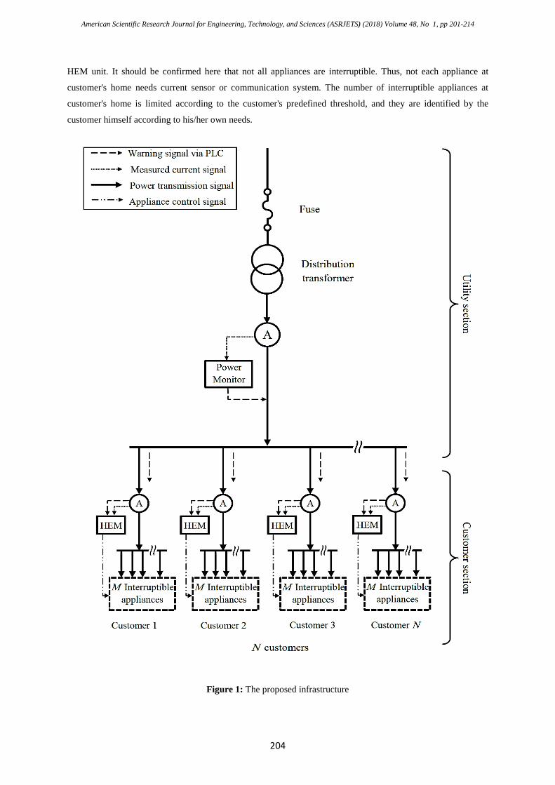
The proposed scheme is based on involving a central power monitor at the secondary side of distribution
transformer. The monitor measures the total current drawn from the transformer. In case of transformer
overloading, the monitor sends warning signals to each consumer supplied through that transformer. The
infrastructure of the proposed scheme is illustrated in Figure 1. In the customer side, a home energy
management (HEM) unit is installed at each customer's home which collects warning signals (from the central
power monitor), the customer’s total current, and the instantaneous values of currents drawn by the interruptible
appliances in building. The interruptible appliances can be specified, any time, by customer. This will give
customers the freedom to select their interruptible appliances by plugging them to the mains through a current
sensing module. Wi-Fi technology can be used for the communication between current sensing modules and
American Scientific Research Journal for Engineering, Technology, and Sciences (ASRJETS) (2018) Volume 48, No 1, pp 201-214
204
HEM unit. It should be confirmed here that not all appliances are interruptible. Thus, not each appliance at
customer's home needs current sensor or communication system. The number of interruptible appliances at
customer's home is limited according to the customer's predefined threshold, and they are identified by the
customer himself according to his/her own needs.
Figure 1: The proposed infrastructure
American Scientific Research Journal for Engineering, Technology, and Sciences (ASRJETS) (2018) Volume 48, No 1, pp 201-214
205
The threshold for each customer depends essentially on the size of distribution transformer and the number of
customers served by that transformer.
Once the HEM unit receives a warning signal, it will compare the instantaneous value of total current with the
predefined current threshold. If it exceeds the threshold, the HEM unit will send switching signals to the
minimum number of interruptible appliances according to the proposed algorithm explained in the following
subsection.
It should be noted here that only nonessential loads will be usually connected to the HEM unit. A nonessential
load is any load that can be deferred for a period of time with little to no effect on comfort level or interruption
of a process. In most situations, the interruptible appliances are appliances that have some sort of thermal
storage such as water heaters, air conditioners or freezers. Thus, the proposed system will not significantly
degrade the customer's comfort level. In contrast, reducing load by turning off some nonessential appliances for
short amounts of time is more acceptable than complete outage of the area in case of transformer overloading.
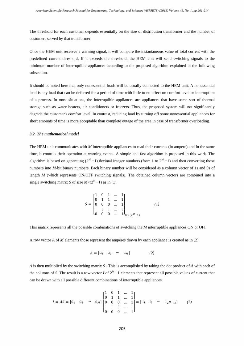
3.2. The mathematical model
The HEM unit communicates with M interruptible appliances to read their currents (in ampere) and in the same
time, it controls their operation at warning events. A simple and fast algorithm is proposed in this work. The
algorithm is based on generating (2M ̶ 1) decimal integer numbers (from 1 to 2M ̶ 1) and then converting those
numbers into M-bit binary numbers. Each binary number will be considered as a column vector of 1s and 0s of
length M (which represents ON/OFF switching signals). The obtained column vectors are combined into a
single switching matrix S of size M×(2M ̶ 1) as in (1).
𝑆𝑆 =
⎣⎢⎢⎢⎡1 0 1 … 10 1 1 … 10 0 0 … 1⋮ ⋮ ⋮ … ⋮0 0 0 … 1⎦
⎥⎥⎥⎤
𝑀𝑀×(2𝑀𝑀−1)
(1)
This matrix represents all the possible combinations of switching the M interruptible appliances ON or OFF.
A row vector A of M elements those represent the amperes drawn by each appliance is created as in (2).
𝐴𝐴 = [𝑎𝑎1 𝑎𝑎2 ⋯ 𝑎𝑎𝑀𝑀] (2)
A is then multiplied by the switching matrix S . This is accomplished by taking the dot product of A with each of
the columns of S. The result is a row vector I of 2M ̶ 1 elements that represent all possible values of current that
can be drawn with all possible different combinations of interruptible appliances.
𝐼𝐼 = 𝐴𝐴𝑆𝑆 = [𝑎𝑎1 𝑎𝑎2 ⋯ 𝑎𝑎𝑀𝑀]
⎣⎢⎢⎢⎡1 0 1 … 10 1 1 … 10 0 0 … 1⋮ ⋮ ⋮ … ⋮0 0 0 … 1⎦
⎥⎥⎥⎤
= [ 𝑖𝑖1 𝑖𝑖2 ⋯ 𝑖𝑖(2𝑀𝑀−1)] (3)
American Scientific Research Journal for Engineering, Technology, and Sciences (ASRJETS) (2018) Volume 48, No 1, pp 201-214
206
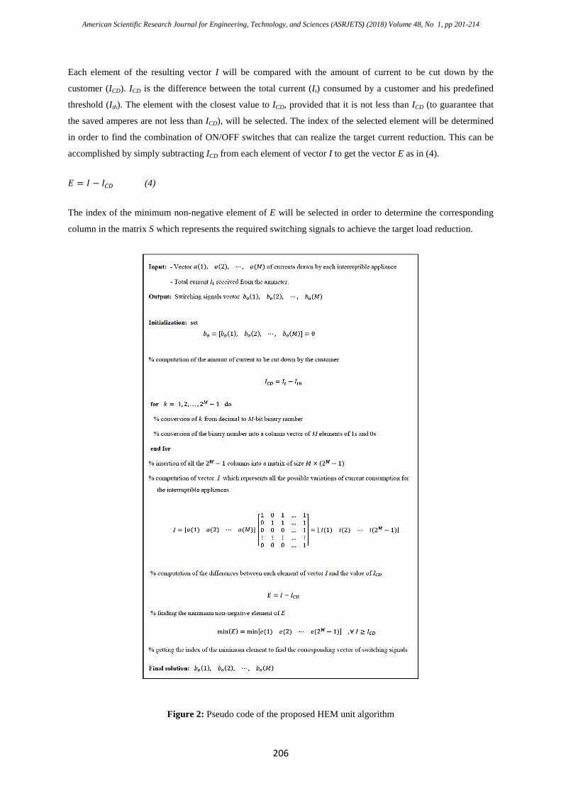
Each element of the resulting vector I will be compared with the amount of current to be cut down by the
customer (ICD). ICD is the difference between the total current (It) consumed by a customer and his predefined
threshold (Ith). The element with the closest value to ICD, provided that it is not less than ICD (to guarantee that
the saved amperes are not less than ICD), will be selected. The index of the selected element will be determined
in order to find the combination of ON/OFF switches that can realize the target current reduction. This can be
accomplished by simply subtracting ICD from each element of vector I to get the vector E as in (4).
𝐸𝐸 = 𝐼𝐼 − 𝐼𝐼𝐶𝐶𝐶𝐶 (4)
The index of the minimum non-negative element of E will be selected in order to determine the corresponding
column in the matrix S which represents the required switching signals to achieve the target load reduction.
Figure 2: Pseudo code of the proposed HEM unit algorithm

American Scientific Research Journal for Engineering, Technology, and Sciences (ASRJETS) (2018) Volume 48, No 1, pp 201-214
207
The proposed algorithm is intended to minimize the number of switched-off appliances to lessen their impact on
the customer's comfort level. The proposed algorithm is further clarified in the pseudo code shown in Figure 2.
4. Methods
MATLAB®/Simulink® was used to carry out the simulation experiments and analysis.
A single-phase power grid model was entirely built using the building blocks of Simulink environment.
For convenience, only four customers were considered in the simulation.
Each customer's house contained two types of appliances: interruptible and uninterruptible appliances. Only four
of the appliances were assumed as interruptible and the rest as uninterruptible appliances.
The uninterruptible appliances were aggregated into a single load for convenience.
Therefore, only twenty different load profiles were considered and randomly generated for the four customers.
Every five profiles were adopted for one customer (four of them were for the interruptible appliances and the
fifth one was for the aggregated uninterruptible appliances).
Each profile is a vector of 24 samples of 1's and 0's.
These samples indicates the operation status of the appliance (i.e. ON or OFF).
The vector was then multiplied by the nominal power consumption of the appliance.
The pseudo code of the proposed home energy management (HEM) algorithm was firstly developed and then
converted into MATLAB programming language to be included in "MATLAB Function" block that can be
found in User-defined library.
This block was then added to each customer's house as a HEM unit.
The phasor simulation method was utilized in this research in order to make the simulation of a whole day very
fast.
In other words, the simulation of the overall power grid for 24 hours (86400 seconds) was executed in several
minutes rather than hours in contrast with the time-domain simulation method.
The system was firstly simulated without the proposed HEM unit and then with the HEM unit involved.
The results of both simulation experiments were compared to validate the proposed technique and to show its
effectiveness to prevent transformer overloading.
American Scientific Research Journal for Engineering, Technology, and Sciences (ASRJETS) (2018) Volume 48, No 1, pp 201-214
208
5. Results and discussion
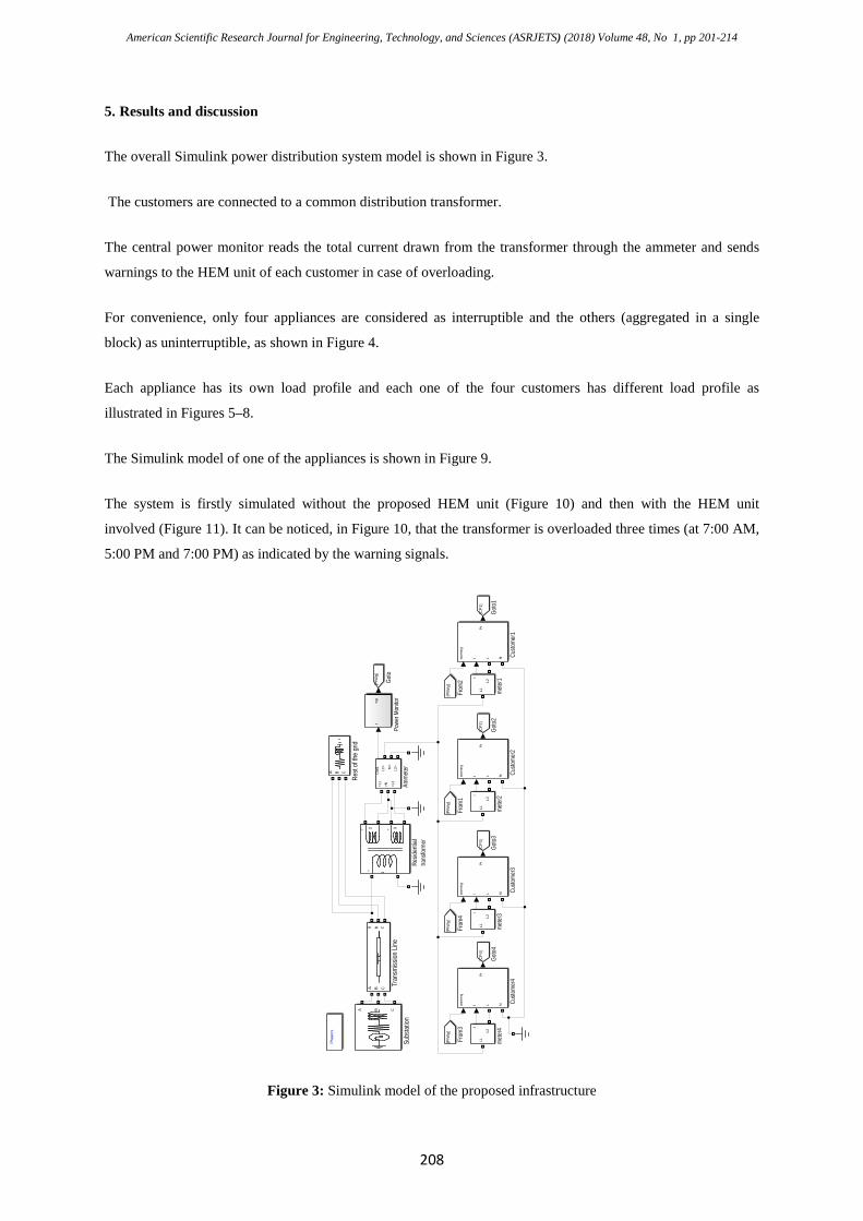
The overall Simulink power distribution system model is shown in Figure 3.
The customers are connected to a common distribution transformer.
The central power monitor reads the total current drawn from the transformer through the ammeter and sends
warnings to the HEM unit of each customer in case of overloading.
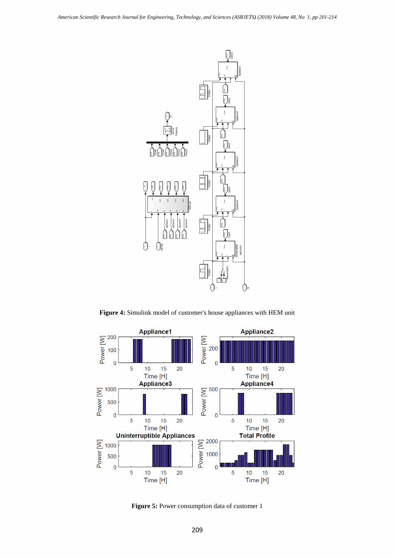
For convenience, only four appliances are considered as interruptible and the others (aggregated in a single
block) as uninterruptible, as shown in Figure 4.
Each appliance has its own load profile and each one of the four customers has different load profile as
illustrated in Figures 5–8.
The Simulink model of one of the appliances is shown in Figure 9.
The system is firstly simulated without the proposed HEM unit (Figure 10) and then with the HEM unit
involved (Figure 11). It can be noticed, in Figure 10, that the transformer is overloaded three times (at 7:00 AM,
5:00 PM and 7:00 PM) as indicated by the warning signals.
Figure 3: Simulink model of the proposed infrastructure
Phas
ors
A B C
Rest
of the
grid
1
2 3
++ +
Resid
entia
l tra
nsfor
mer
a b c
A B C
Tran
smiss
ion Li
ne
Out
1>L
1
>N >L2
L1> N>
L2>
Amme
ter
[PIW
g]
Goto
Iw
g
Powe
r Mon
itor
I
L1
L2
meter
1
[PIW
g]
From
2
A B C
Subs
tation
[CP
1]
Goto1
war
ning
I
Pt
L N Custo
mer1
I
L1
L2
meter
2
[PIW
g]
From
1
[CP
2]
Goto2
war
ning
I
Pt
L N Custo
mer2
I
L1
L2
meter
4
[PIW
g]
From
3
I
L1
L2
meter
3
[PIW
g]
From
4
[CP
3]
Goto3
[CP
4]
Goto4
war
ning
I
Pt
L N Custo
mer3
war
ning
I
Pt
L N Custo
mer4
American Scientific Research Journal for Engineering, Technology, and Sciences (ASRJETS) (2018) Volume 48, No 1, pp 201-214
209
Figure 4: Simulink model of customer's house appliances with HEM unit
Figure 5: Power consumption data of customer 1
[SW
1]
[SP
]
2 I 1
warn
ing[P
A1]
[PA
2]
[PA
3]
[PA
4]
[SW
2]
[SW
3]
[SW
4]
[PA
1]
From
8[P
A2]
From
9[P
A3]
From
10[P
A4]
From
11[P
A5]
From
12
Sum
ofEl
emen
ts
1 Pt
1 L 2 N
1
Manu
al Sw
itch
0
[PA
1]
Goto1
0
[SW
2][S
W3]
[SW
4][P
A2]
Goto1
[PA
3]
Goto2
[PA
4]
Goto3
[PA
5]
Goto4
Pro
file
SW
Pow
er
L N Appli
ance
1
Profi
le1 [SW
1]
Pro
file
SW
Pow
er
L N Appli
ance
2
Pro
file
SW
Pow
er
L N Appli
ance
3
Pro
file
SW
Pow
er
L N Appli
ance
4
Pro
file
SW
Pow
er
L N Unint
erru
ptible
Appli
ance
s
Profi
le2Pr
ofile3
Profi
le4Pr
ofile5
[I]
It Wg
Ai1
Ai2
Ai3
Ai4
SP
SW
1
SW
2
SW
3
SW
4
HEM
unit
Appli
ance
1
Appli
ance
2
Appli
ance
3
Appli
ance
4
American Scientific Research Journal for Engineering, Technology, and Sciences (ASRJETS) (2018) Volume 48, No 1, pp 201-214
210
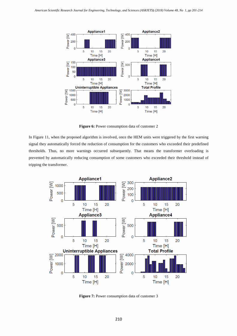
Figure 6: Power consumption data of customer 2
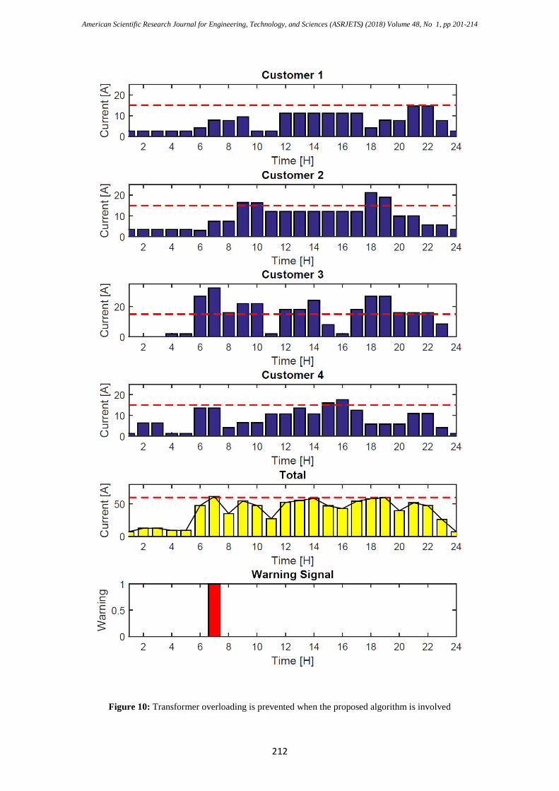
In Figure 11, when the proposed algorithm is involved, once the HEM units were triggered by the first warning
signal they automatically forced the reduction of consumption for the customers who exceeded their predefined
thresholds. Thus, no more warnings occurred subsequently. That means the transformer overloading is
prevented by automatically reducing consumption of some customers who exceeded their threshold instead of
tripping the transformer.
Figure 7: Power consumption data of customer 3
American Scientific Research Journal for Engineering, Technology, and Sciences (ASRJETS) (2018) Volume 48, No 1, pp 201-214
211
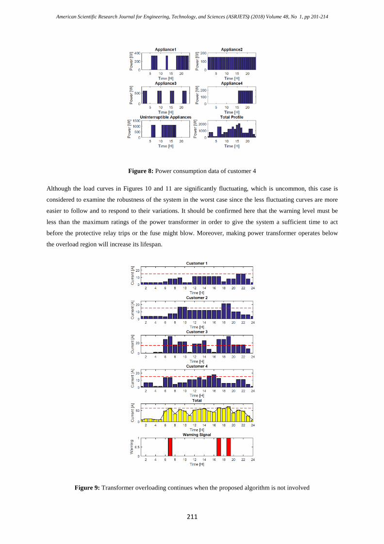
Figure 8: Power consumption data of customer 4
Although the load curves in Figures 10 and 11 are significantly fluctuating, which is uncommon, this case is
considered to examine the robustness of the system in the worst case since the less fluctuating curves are more
easier to follow and to respond to their variations. It should be confirmed here that the warning level must be
less than the maximum ratings of the power transformer in order to give the system a sufficient time to act
before the protective relay trips or the fuse might blow. Moreover, making power transformer operates below
the overload region will increase its lifespan.
Figure 9: Transformer overloading continues when the proposed algorithm is not involved
American Scientific Research Journal for Engineering, Technology, and Sciences (ASRJETS) (2018) Volume 48, No 1, pp 201-214
212
Figure 10: Transformer overloading is prevented when the proposed algorithm is involved
American Scientific Research Journal for Engineering, Technology, and Sciences (ASRJETS) (2018) Volume 48, No 1, pp 201-214
213
6. Limitations of the study
Although the simulation results have been satisfactory, the proposed strategy should have been experimentally
implemented in a real-world power sub-grid to support the simulation results. Unfortunately, there were no
available permission to utilize a real-world transformer even with a small number of customers. However, this
can be considered in future work.
7. Conclusion
Many different protection strategies have been proposed in the literature. These strategies differ in their
complexity and cost. However, most of these strategies focus on the protection of power transformer without
taking the prevention of service discontinuity into consideration. Additionally, some of the strategies are not
feasible to be implemented in most of developing countries.
A simple and effective strategy is proposed in this paper that can prevent transformer overloading and, in the
same time, it avoids transformer tripping and consequently prevents power disconnection. Furthermore, the
strategy can be implemented in developing countries at reasonable cost.
The simulation results show that once the total current drawn from the transformer reaches a threshold level, the
power monitor sends warning signals to the customers and the HEM units switch off the minimum number of
interruptible appliances that expected to reduce the consumption and stop the warning. This strategy protects the
power transformer from being overloaded without isolating it from the rest of grid and thus prevents major
power outage of an entire area. The experimental implementation of the proposed scheme can be considered in
future work based on low-cost microcontrollers. Power line communication (PLC) technology can be utilized to
send the warning signals over existing power cables.
References
[1] H. R. Braunstein. “Alternatives for fault and overload protection of pad mounted distribution
transformers.” 1979 7th IEEE/PES Transmission and Distribution Conference and Exposition. Atlanta,
Georgia, 1979. pp. 484-493.
[2] G. Rockefeller. “Fault protection with a digital computer.” IEEE Transactions on Power Apparatus and
Systems, 88(4), pp. 438-464, 1969.
[3] A. Girgis, D. Hart and W. Chang. “An adaptive scheme for digital protection of power transformers.”
IEEE Transactions on Power Delivery, 7(2), pp. 546-553, 1992.
[4] M. Zaman, and M. Rahman. “Experimental testing of the artificial neural network based protection of
power transformers.” IEEE Transactions on Power Delivery, 13(2), pp. 510-517, 1998.
[5] L. Kojovic, M. T. Bishop and D. Sharma. “Innovative differential protection of power transformers
using low energy current sensors.” 2009 IEEE Industry Applications Society Annual Meeting, Houston,
TX, 2009, pp. 1-8.
[6] L. Sevov, Z. Zhang, I. Voloh and J. Cardenas. “Differential protection for power transformers with non-
standard phase shifts.” 2011 64th Annual Conference for Protective Relay Engineers, College Station,
American Scientific Research Journal for Engineering, Technology, and Sciences (ASRJETS) (2018) Volume 48, No 1, pp 201-214
214
TX, 2011, pp. 301-309.
[7] O. Ozgonenel and S. Karagol. “Transformer differential protection using wavelet transform.” Electric
Power Systems Research, 114, pp. 60-67, 2014.
[8] E. Ali, A. Helal, H. Desouki, K. Shebl, S. Abdelkader and O. Malik. “Power transformer differential
protection using current and voltage ratios.” Electric Power Systems Research, 154, pp. 140-150, 2018.
[9] M. Tripathy, R. Maheshwari and H. Verma. “Advances in transformer protection: a review.” Electric
Power Components and Systems, 33(11), pp. 1203-1209, 2005.
[10] Z. Bo, X. Lin, Q. Wang, Y. Yi and F. Zhou. “Developments of power system protection and
control.” Protection and Control of Modern Power Systems, 1(1), pp. 1-8, 2016.
[11] A. Naseem and N. Alam. “Protection of distribution transformer using Arduino platform.” Science
International, 27(1), pp. 403-406, 2015.
[12] K. Trivedi, C. Vibhakar and R. Sardhara. “Differential Protection of Transformer Using Arduino with
GSM and Voice Circuit.” International Journal of Novel Research and Development, 2(4), pp. 95-100,
2017.