A Service Discipline for Support of IP QoS in IEEE 802.11 Networks
20
A Service Discipline for Support of IP QoS in IEEE802.11 Networks António Grilo, Mário Macedo and Mário Nunes INESC, R. Alves Redol, N o 9, 1000 Lisboa, PORTUGAL Email: amg @ cris.inesr.pt Key words: Abstract: 802.11, IP QoS, Scheduling Discipline, Discrete Event Simulation. This paper presents a QoS aware service discipline based on estimated transmission times for use in IEEE 802.11 networks. This algorithm works based on the flow specifications defined by the IETF for the IP QoS reference models, coupling layer 2 and layer 3 QoS. Simulation results show that the proposed service discipline performs better than Weighted Round Robin in IEEE 802.11b networks, providing a better optimisation of network resources while fulfilling the QoS requirements of real-time services such as packet telephony and videoconference. 1. INTRODUCTION Wireless LANs (WLANs) are becoming a major growth factor for the wireless networks industry, promising to replace most wired LAN infrastructures in the near future. The main advantage of WLANs over their wired counterparts is the increased mobility, allowing users to roam inside their enterprise or campus without interrupting their communication sessions. The mostly commercialised WLAN products are nowadays based on the IEEE 802.11 standard [1]. The physical layer was firstly designed to work in the 2.4 GHz frequency band. Starting with a bit rate of 2 Mbps, it reached 11 Mbps with 802.1lb. This will be followed by 802.1la, which works in the 5 GHz band and is able to provide bit rates as high as 54 Mbps.
Transcript of A Service Discipline for Support of IP QoS in IEEE 802.11 Networks
A Service Discipline for Support of IP QoS in IEEE802.11 Networks
António Grilo, Mário Macedo and Mário Nunes INESC, R. Alves Redol, No9, 1000 Lisboa, PORTUGAL
Email: amg @ cris.inesr.pt
Key words:
Abstract:
802.11, IP QoS, Scheduling Discipline, Discrete Event Simulation.
This paper presents a QoS aware service discipline based on estimated transmission times for use in IEEE 802.11 networks. This algorithm works based on the flow specifications defined by the IETF for the IP QoS reference models, coupling layer 2 and layer 3 QoS. Simulation results show that the proposed service discipline performs better than Weighted Round Robin inIEEE 802.11b networks, providing a better optimisation of network resourceswhile fulfilling the QoS requirements of real-time services such as packet telephony and videoconference.
1. INTRODUCTION
Wireless LANs (WLANs) are becoming a major growth factor for the wireless networks industry, promising to replace most wired LAN infrastructures in the near future. The main advantage of WLANs over their wired counterparts is the increased mobility, allowing users to roam inside their enterprise or campus without interrupting their communication sessions. The mostly commercialised WLAN products are nowadays based on the IEEE 802.11 standard [1]. The physical layer was firstly designed to work in the 2.4 GHz frequency band. Starting with a bit rate of 2 Mbps, it reached 11 Mbps with 802.1lb. This will be followed by 802.1la, which works in the 5 GHz band and is able to provide bit rates as high as 54 Mbps.

122 António Grilo, Mário Macedo and Mário Nunes
Simultaneously with the growth of wireless communications there is the trend for multimedia communications over IP with Quality of Service (QoS) support. The use of multimedia communication services such as telephony, videoconference and streamed video over IP is now a reality in corporate networks and promises to expand to the global Internet. This has prompted the IETF to develop the IntServ and DiffServ reference models for QoS support in IP networks.
This paper addresses both issues, presenting a solution for QoS support in 802.11 networks4. The proposed solution can be easily adapted to otherWLAN technologies. The paper is focused on a scenario of wireless accessto a high performance IP core network, as can be found in corporate oruniversity environments. In order to support end-to-end QoS and avoid traffic bottlenecks at the radio access interface, layer 3 and layer 2 QoS must be closely coupled. This is achieved by a QoS aware scheduling algorithmthat works on top of the current 802.11 MAC layer and whose input consists of IP QoS parameters. Performance evaluation is attained through software simulation and considers 802.1lb, which is now widely accepted.
2. THE IEEE802.11 MAC
The QoS support mechanisms defined for the MAC layer of IEEE 802.11are quite basic. The standard defines only two priority values for a data packet: Contention and ContentionFree. The former specifies that data is to be transmitted by means of the Distributed Coordination Function (DCF), which uses a CSMA/CA mechanism. The latter specifies data transmission during the Contention Free Periods (CFPs) using a polling mechanism controlled by the Point Coordination Function (PCF) at the Access Point(AP). Within a cell, DCF and PCF modes are time multiplexed under the control of the AP (see Figure 1). A superframe is formed by a CFP followedby a contention period.
4 The work presented is partially funded by the European Union in the framework of the ISTprogram project MOICANE. The authors alone are responsible for the content of the paper.

A Service Discipline for.. . 123
Figure 1. Beacons and contention free periods
During the time interval between two CFPs, the WLAN works in DCFmode using CSMA/CA for transmission. If the end of the DCF occurs during the transmission of a packet, the start of the next CFP is delayed until the packet source ends transmission (this may only happen after all fragments of the packet are successively transmitted or the dwell time boundary expires). Additionally, the CFP is shortened in order to finish at the due time (this is illustrated by the second CFP in Figure 10). These delays and lack of preemptive control present an obvious difficulty for the handling of real-timetraffic. For this reason, the dwell time boundary of the DCF should be carefully selected. On the other hand, the DCF mode cannot be eliminated because registration of terminals with the PCF takes place in DCF mode.
Packet priorities are implemented by defining 3 IFSs (Interframe Spaces) of different lengths: . SIFS (Short IFS): This is the shortest IFS. It is used for transmission
of high priority packets: Acknowledgements of data packet fragments,CTS frames, PCF DATA frames and DCF DATA frames (except the firstfragment of a MAC SDU). . PIFS (PCF IFS): This is greater than SIFS. After this interval expires,any PCF mode frames can be transmitted. . DIFS (DCF IFS): This is greater than PIFS. After this intervalexpires, any DCF mode frames can be transmitted asynchronouslyaccording to the backoff mechanism (see below). The DCF mode is based on a CSMA/CA mechanism. The access control
scheme is shown in Figure 2.

124 António Grilo, Mário Macedo and Mário Nunes
Figure 2. Backoff mechanism in DCF
A station that intends to transmit and senses the channel busy will wait for the end of the ongoing transmission, then wait for a time period of DIFSlength, and then randomly selects a time slot within the backoff window. Ifno other station started transmitting before this slot is reached (i.e. another station that selected an earlier slot) it starts the transmission of a fragment with maximum size aFragmentationThreshold. Collisions can now only occur in the case that two stations have selected the same slot. If another station has selected an earlier slot, the station freezes its backoff counter, waits for the end of this transmission and now only waits for the slots remaining from the previous competition. After the successful transmission of the first fragment of an MSDU, the remaining fragments are transmitted is succession separated by a SIFS interval. Transmission ends when all fragments of an MAC SDU (MSDU) are transmitted or the maximum dwelltime expires.
In order to guarantee undisturbed transmission even if hidden terminals are present, an RTS/CTS mechanism is used. When this mechanism isapplied, the contention winner does not transmit the data immediately. Instead it sends an RTS frame to which the receiver answers with a CTS frame. This guarantees that all stations in the range of either the sender or the receiver know that a packet will be transmitted. Only then the sendertransmits the data frames. While the two extra messages present additional overhead, the mechanism is specially useful in the case of large data packets.
The PCF mode is based on a polling mechanism controlled by the AP as depicted in Figure 3.

A Service Discipline for ... 125
Figure 3. Polling mechanism in PCF
During the CFP, the AP polls the stations registered on its polling list and allows them undisturbed contention free access to the medium. As already said, in order to get on the polling list the STAs have to apply once during the DCF period. The maximum duration of a CFP is given by the 802.11 Management Information Base (MIB) variable aCFPMaxDuration.
During the CFP a frame can be a composite of control and data information. As such, the following combinations are allowed for PCF frames: DATA; CF-ACK, CF-POLL, DATA+CF-ACK; DATA+CF-ACK+CF-POLL and CF-ACK+CF-POLL. Only the AP has the capability to issue frames with CF-POLL. The STAs can only answer with DATA, CF-ACK or DATA+CF-ACK. Each polling request must be answered with themaximum of 1 data fragment of maximum size aFragmentationThreshold.If the STA does not answer a polling request within an interval of PIFS, theAP concludes that the STA has nothing to transmit and resumes CFP bysending downlink data and/or polling another STA.
It is useful to evaluate the maximum throughput that can be achieved with the PCF. Considering that all fragments have the same size, themaximum throughput achieved by the PCF mode can be approximated bythe following expression:
=
The average fragment transmission time is then the average betweenuplink and downlink fragment transmission times. As already seen, thetransmission of a fragment in the uplink direction involves the transmissionof a CF_POLL frame, followed by a DATA frame and finally a CF_ACKframe, while in the downlink direction no polling frame is needed. As such,the average fragment transmission time can be calculated as follows,considering piggyback of acknowledgements for uplink traffic:
MaxThroughput =aCFPMaxDuration ×
frgment_sizesuperframe_duration fragment_time

126 António Grilo, Mário Macedo and Mário Nunes
_
+ DATA _ time + CF _ ACK _ time
The transmission of a frame involves the transmission of a physical layer preamble and header at the lowest bit rate (1 Mbps), followed by the MACPDU (MPDU) transmitted at the PSDU bit rate. As such, the time taken to transmit a CF_POLL frame is the following.
The time taken to transmit a CF-ACK frame is calculated in a similar way:
The time taken to transmit a DATA frame is calculated as follows:
Both DCF and PCF have advantages that can be exploited in theappropriate context. DCF is the most appropriate in a context where there is no network infrastructure and users must form temporary ad hoc networks to communicate directly between each other. The literature provides some interesting publications on the evaluation [2] and improvement [3] [4] [5] of the 802.11 CSMA/CA algorithm.
On the other hand, if the objective is to offer a permanent network infrastructure to provide access to the Intranet/Internet with guaranteed QoS bounds, PCF is the best choice. This is the scenario considered in the present paper.

A Service Discipline for ...
3. IP QOS PARAMETERS
127
The IETF has defined two main models for QoS support in IP networks: Integrated Services (IntServ) and Differentiated Services (DiffServ).
IntServ was created to provide end-to-end QoS. The ResourceReservation Protocol RSVP [6] protocol is used for signalling QoS requests from the application to the network. In this model, the originator endpoint uses the RSVP PATH message to advertise the bandwidth requirements of a flow. That message traverses the network routers until it reaches the destination endpoint. The destination compares the required resources with the available resources and answers with a RSVP RESV message. This message travels all the way back making resource reservation for the flow at each traversed router. The IntServ model specifies three main service classes: Guaranteed Service (GS), Controlled Load (CL) and Best Effort (BE). The GS class presents the highest level of QoS guarantee, while theBE calss presents the lowest level.
Due to the scalability problems of IntServ, the IETF developed a simplerQoS model called DiffServ [7]. In this model, user flows are only controlled at the edge of network domains, being classified in one of several classes.Within a network domain, all flows that belong to the same class are aggregated and forwarded with the same priority. Until now the IETF has identified three main traffic classes or per-hop behaviours (PHB): Expedited Forwarding (EF), Assured Forwarding (AF) and Best Effort (BE). These PHBs correspond roughly to the service classes defined for IntServ. The EF class is to be used for high priority services with tight QoS bounds, such as packet telephony, its main application being the support of virtual leased lines. The AF class has lower priority than EF, but it is still able to providesome QoS guarantees. Finally, the BE class is suitable for less demandingservices, using the resources left by EF and AF.
The IP QoS parameters for a flow form a flow specification (FlowSpec) [8]. FlowSpecs are used in both IntServ and DiffServ.
In a FlowSpec, the transmission rate is parameterised as a token bucket.A token bucket has a maximum volume (Token Bucket Size) and continuously fills in at a certain byte rate (Token Rate), which corresponds to the average transmission rate. If the bucket becomes full, the incoming tokens will be thrown away. If the token bucket contains sufficient credit, the application may send data; reducing the available credit by that amount. If sufficient credits are not available, the application must wait or discard the extra traffic. If an application has been sending at a low rate for a period of time, it clearly may send a large burst of data at once with a rate not higher than Peak Rate until it runs out of credit. Having done so, it must limit itself to sending at Token Rate until its data burst is exhausted. In constant rate

128 António Grilo, Mario Macedo and Mário Nunes
applications, the Token Rate is equal to the Peak Rate, and the Token BucketSize is chosen to accommodate small variations.
Another important FlowSpec parameter is the Maximum Transmission Unit (MTU), which is the maximum packet size, in bytes, generated by thehost.
Transmission delay is also important. While some applications such asWeb access are not very sensitive to delay, real-time services such as telephony demand minimum delay in order to achieve acceptable quality. The Maximum Delay of a service is the maximum acceptable delay between transmission of a bit by the sender and its reception by the intended receiver(s), usually expressed in microseconds. If a receiving application requires data to be delivered in the same pattern that the data was transmitted, it may be necessary for the receiving host to briefly buffer data as it is received so that the receiver can restore the old transmission pattern.An easy example of this is a case where an application wishes to transmit data such as voice samples, which are generated and played at regular intervals. The regular intervals may be distorted by queuing effects in the network and the receiver may have to restore the regular spacing. The amount of buffer space that the receiving host is willing to provide determines the Maximum Delay Variation (delay variation is also known asjitter) permitted for individual packets within a given flow.
The Loss Sensitivity parameter states how sensitive the flow is to losses. The Loss Sensitivity is defined as the number of MTU-sized packets thatmay be lost out of the number of MTU-sized packets specified in the Loss Interval parameter. Another useful parameter is the Burst Loss Sensitivity, which states how sensitive the flow is to losses of consecutive packets. It is defined as the maximum number of consecutive MTU-sized packets thatmay be lost.
Finally, the Quality of Guarantee specifies the level of commitment of the network towards the QoS parameters. As we have already seen, thiscorresponds to the service classes of IntServ and DiffServ. Throughout the rest of this paper, the DiffServ service classes will be used to characterisethis parameter.
4. SCHEDULING IN 802.11
Among the common service disciplines that could be used to implement the IEEE 802.11 PCF, we have identified two main families: Weighted Fair Queuing (WFQ), and Weighted Round Robin (WRR) [9].

A Service Discipline for ... 129
WRR was chosen for performance benchmarking because it is widely accepted and simple to adapt to a WLAN environment, as it needs no information about the queued messages at the STAs or AP.
On the other hand, WFQ is difficult to adapt to a polling mechanism like the IEEE 802.11 PCF, since there is no way for the AP to know neither about the presence of queued packets at the terminals nor the packetgeneration times. The same difficulties apply to other WFQ familydisciplines, such as W2FQ, and W2FQ+. Nevertheless, it is possible to estimate the presence of packets on the terminal’s queues, and therefore implement a version of WFQ based on packet presence expectations if we observe the leaky bucket’s state. If the leaky bucket is empty, it is more probable that the corresponding terminal has already one packet to transmit than if the leaky bucket is full. However, this procedure is not accurate,because it only indicates a probability of packet generation.
Most packet scheduling disciplines are not specially designed to meet QOS constraints such as those of IP QoS models. For example, RFC 2598[10] suggests the use of simple priority for EF traffic on the DiffServ routers, as an alternative to simple WRR, in order to implement a low delay, and alow jitter service for the EF.
4.1 Weighted Round Robin
The Weighted Round Robin (WRR) service discipline can be easily adapted to the IEEE802.11 environment. The algorithm generates a polling rate proportional to the weight of the flows, but it also tries to distribute the polls as uniformly as possible. The algorithm has similarities with the DeficitWeighted Round Robin algorithm [9].
Let FRavi be the average fragment rate of flow i, while LFi is the averagefragment length. The weight of each flow i,Φ i is calculated by theexpression:
Let Ci be the transmission credit of flow i. The WRR algorithm can beimplementated as follows:
1. Init all Ci =0;2. Choose m such that Cm = max(Ci). If there are many equals,
choose the first. i
3. Send a poll to flow m;

130 António Grilo, Mário Macedo and Mário Nunes
4. Decrease the credits of flow m making Cm = Cm –1 anddistribute those credits among all flows making Ci = Ci + i ;φ
5. Go to step 2.
Note that this algorithm can only work with acceptable performancewhen the low level traffic characteristics of the sources are well known. In practice FRavi and LFi are not known in advance as these parametersdependent on layer 2.
4.2 Scheduling based on Estimated Transmission Times
The service discipline proposed in this paper bases its scheduling decisions on the estimated packet transmission times (SETT - Schedulingbased on Estimated Transmission Times). A similar procedure was used for the rt-VBR traffic scheduling in IEEE802.14 networks [11].
A variable tpoll is associated to each flow, representing the estimatedtransmission time of a burst from the source, and therefore the more or lessideal time for the AP to issue a poll to the source. Tpolling is a variable thatrepresents the time interval between polls to be issued to that flow.
SETT issues a poll to the flow that has the minimum tpoll <= t, where t is the real time clock of the system. Each time a station is polled, the next tpoll iscalculated as tpoll = tpoll + Tpolling.
When a flow is bursty, those polls are used to detect the beginning of theburst. After the detection, SETT enters a transmission procedure where theflow is polled at the maximum possible rate, not higher than the Peak Rate.
The burst detection algorithm provides different treatment for each service class:
A. AlgorithmforEFflows
Generally, EF flows have a contracted transmission rate Rav (Token Rate)and a Token Bucket Size σ. Other relevant parameters of EF flows are MTU,the Peak Rate and Tdmax (end-to-end Maximum Delay).
For the EF flows, SETT will try to transmit all the bucket size within afraction α of Tdmax leaving enough time to be spent throughout the corenetwork and destination access network. Let LF be the length of the longestallowed fragment of a flow. LF is calculated as follows:
LF = min (MTU , aFragmentationThresh old)
The polling interval Tpolling for detecting the beginning of a burst is givenby:

A Service Discipline for... 131
The polling interval Tpolling is the minimum value between the mean inter-fragment period and the fraction of the detection latency, which is the maximum latency that can be used to detect the burst at the access network.
For constant rate flows, this polling interval implies an average access delay not higher than the average inter-fragment period. Also for this type offlows, this also allows us to comply with the contracted Token Rate for the flow, Rav.
If the delay requirements are severe, the detection latency term will result in a lower polling interval. For sources with long bursts (high σ), thealgorithm must guarantee that all fragments of the burst are transmitted within the fraction of Tdmax allotted to the access network. As such, thepolling interval will depend on the ratio between σ i and LF, but not higherthan parameter β.
B. Algorithm for AF flows
Generally, AF flows have a contracted average transmission rate Rav
(Token Rate) and a token bucket size σ. Other relevant parameters of the AFflows are the MTU, and the Peak Rate.
For an AF flow, the algorithm is similar to the EF procedure describedabove, the only difference being the computation of the polling interval, which now is given by:
LFTpolling = Rav
This is due to the fact that the delay bounds are not as severe for AF than for EF.
C. Algorithm for Best-Effort flows
Best-Effort flows have no QOS requirements. As such, scheduling of BEflows is reduced to a plain Round Robin service discipline, with polls being issued whenever there are no pending polls for the EF or AF service classes. This procedure allows the even distribution of free capacity among the BE

132 António Grilo, Mário Macedo and Mário Nunes
flows. The AF flows are also included in the Round Robin cycle as they should also benefit from extra bandwidth, as suggested in RFC 2597 [ 12]. However, the transmission rates for the AF flows can never exceed thespecified Peak Rate.
5. SIMULATION RESULTS
The SETT and WRR algorithms were simulated using a discrete eventsimulator developed at INESC. The engine of the simulator was already usedin the past to study the performance of the DECT Packet Radio System [13]. The simulator allows the manipulation of some of the parameters that constitute the 802.11 MIB. The parameterisation used in this simulation is shown in Table 1.
Table 1. Simulation parameters 802.11 parameters ASlotTime 20 ms
aFragmentation 1024 bytes Threshold
SIFS 20 µs PIFS 30 µs DIFS 40 µs Beacon Interval 100 ms DTIM Interval 3aCFPMaxDuration 880 ms aCFPRate 3PLCP sublayer DSSSPLCP overhead 192 bits
PLCP preamble 1 Mbps andheader bit rate
PSDU bit rate 11 Mbps (802.11 b)SETT parameters α 0.40
β 6

A Service Discipline for... 133
802.11 parameters ASlotTime 20 ms
Physical medium Frame Loss Ratio 0%parameters
802.1 1 parameters ASlotTime 20 ms
As can be seen, a CFP occupies 880 ms (aCFPMaxDuration) of each superframe of 900 ms (aCFPRate × DTIM Interval × Beacon Interval).Such a parameterisation assumes that all data traffic is transmitted during the CFP, relegating the contension period for the exchange of management andcontrol information. It also assumes a scenario of fixed wireless access where mobility is negligible (e.g. within a room). Otherwise a handover delay of 880 ms would not be admissible. The frame loss ratio due to physical layer errors is 0%, which is not very far from the truth in a corporate environment.
During the simulations we have considered three types of traffic sources:bursty data (e.g. HTTP sessions), VoIP and video.
The model for bursty data sources follows the Source Type 1 defined for802.14 performance evaluation [14], which consists on a Poisson distribution, where message sizes and respective probabilities are thefollowing: (64, 0.6), (128, 0.06), (256, 0.04), (512, 0.02), (1024, 0.25) and(15 18,0.03). In our simulations, each busty data source generates 200 Kbps.
The audio source model generates new messages with a constant rate andsize. We have considered 8 Kbps audio sources (G.729) where 20-bytemessages are periodically generated with an interval of 20 ms. We have also considered an RTP/UDP/IP overhead of 40 bytes per message, which resultsin an overall bit rate of 24 Kbps (60 bytes per message).
For the video source model we have considered a frame rate of 15frames-per-second (fps), with one key-frame (synchronization frame which uses only intraframe compression, such as the I frame in MPEG) being generated once in every 15 frames. Each source generates video at 250 Kbps and each key-frame is 28032 bytes long. The size of the other frames isgiven by a normal distribution (µ,σ)=(229,20).
In the simulations, each wireless terminal runs only one session and allsessions are bi-directional, i.e. each terminal is the source of uplink data and the sink of downlink data for the session it runs.
Each traffic type is assigned a RFC 1363 flow specification, as providedin Table 2. The SETT algorithm uses only a subset of the FlowSpec parameters. Note that the maximum delay values for audio and video represent end-to-end delay. ITU-T recommendation G. 114 [15] specifies a Maximum Delay of 150 ms for telephony. As already seen, SETT will try to

134 António Grilo, Mário Macedo and Mario Nunes
spend no more than 40% (parameter α ) of that Figure (i.e. 60 ms) in the access network in order to leave enough time to be spent in the core (20%) and destination access (40%) networks. Video is considered to be real-time(e.g. videoconference) and as such it presents the same Maximum Delayparameter as VoIP. The tests only address the EF and BE service classes. The AF service class is left for further study.
Table 2. Flow specifications for the several traffic types
ParametersQOS Data VoIP Video
Service BE EF EF
Token Rate 24 Kbps 250 KbpsToken Burst 120 Bytes 28032 Bytes
Peak Rate 24 Kbps 11 Mbps MTU 60 Bytes 28032 Bytes Maximum 150 ms 150 ms
QoS Data VoIP Video
Class
Size
Delay
Parameters
The first experiment considers a video session running simultaneously with n VoIP sessions. Figure 4 shows the average packet delay for the VoIP streams (it includes both uplink and downlink values) as n increases. As can be seen, WRR performs better than SETT. Nevertheless, the average packet delay of SETT is kept slightly higher than 10 ms for less than 16 VoIP sessions, which is acceptable for telephony. Above 17 VoIP sessions, average delay is unacceptable (i.e. above 60 ms) for both scheduling disciplines.
--
--
-

A Service Discipline for ... 135
Figure 4. Simulation 1 : Average packet delay (ms) for the VoIP streams.
The maximum packet delay is depicted in Figure 5. It shows that SETTstarts to present delay values of more than 60 ms with more than 15 VoIP sessions. In WRR, maximum packet delay rises more smoothly, going above 60 ms only with more than 17 VoIP sessions.
Figure 5. Simulation 1: Maximum packet delay (ms) for the VoIP streams.

136 António Grilo, Mario Macedo and Mário Nunes
The average packet delay for the video session is depicted in Figure 6. Although WRR performs slightly better in the beginning, SETT starts to perform better for more than 5 VoIP sessions. Above 8 VoIP sessions, thedelay presented by SETT is less than 50% of the delay presented by WRR. Above 12 VoIP sessions, average delay rises above 60 ms for WRR, whilefor SETT this only happens with more than 15 VoIP sessions.
The maximum packet delay is depicted in Figure 7 and shows that maximum delay rises above 60 ms from the beginning for both servicedisciples, though SETT performs always better than WRR. This is due to the keyframes of 28032 bytes, which would need 3.7 Mbps to be transmitted in 60 ms. Although the instantaneous physical bit-rate is 11 Mbps, this value is impossible to achieve due to the overhead. As such, videoconference transmission over 802.1lb can be hampered by high delays. A solution is to use the key-frames for decompression of the smaller frames that follow, not showing them to the user. The impact of this technique in the qualityperceived by the user must be evaluated. With 802.1 la at bit-rate higher than 20 Mbps this problem will probably cease to exist.
Figure 6. Simulation 1 : Average packet delay (ms) for the video stream
A Service Discipline for... 137
Figure 7. Simulation 1 : Maximum packet delay (ms) for the video stream.
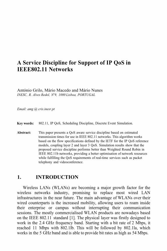
The second experiment considers a video session running simultaneously with 2 VolP sessions and n bursty data sessions, with increasing n. As delay is not much relevant for BE flows, Figure 8 depicts the throughput instead. This is the sum of uplink and downlink throughput values. As can be seen,the disciplines have similar performance. Throughput starts to rise, achieving a maximum of approximately 3 Mbps with 8 data sessions for SETT. WRR rises a little above that value (3300 Mbps), at the cost of audio and videoperformance as will be shown.
Figure 8. Simulation 2: Throughput (Kbps) of bursty data streams

138 António Grilo, Mário Macedo and Mário Nunes
It is important to note that the maximum throughput achieved (around 3 Mbps) stays well below the physical limit of 11 Mbps. This is due to the overhead introduced by the Physical and MAC layers. Knowing thatCF_POLL_size and CF_ACK_size are both equal to 14 bytes and thatDATA_header_size is equal to 34 bytes according to the standard,substituting the simulation parameters in the formula for the maximumthroughput of PCF (see above) we reach the curve depicted in Figure 9
Figure 9. Maximum throughput of 802.11 b versus MAC fragment size
The average fragment size of the bursty data sources is approximately 357 bytes, as can be easily calculated from the message size distribution.This fragment size corresponds to a maximum throughput of 3.5 Mbps, which approximately matches the value achieved for data sources in the simulation. The small difference is explained by the VoP and video sources (a total load of 596 Kbps) in the simulation and the nonlinearity of the maximum throughput function.
Figure 10 shows the average packet delay for the VoP and video sessions. As can be seen, SETT is not affected by the increase in the number of data sessions, always presenting delay values around 10 ms. As expected, the WRR service discipline offers no protection to the video and VoP streams, whose delay values start to rise fast for a number of data sessions above 5 and 10 respectively.

A Service Discipline for... 139
Figure 10. Simulation 2: Average packet delay (ms) for the VoIP and video streams
6. CONCLUSIONS
This paper has presented a QoS aware Service Discipline that supports IPQoS in IEEE 802.11 access networks. This service discipline bases its scheduling decisions on the estimated packet transmission times (SETT -Scheduling based on Estimated Transmission Times), whose computations are based on the parameters defined in RFC 1363 for FlowSpecs.
SETT was simulated in an 802.11b environment and compared with the Weighted Round Robin (WRR) service discipline, considering sources ofthree different types: bursty data, IP telephony (VoIP) and real-time video. Experiments showed that in general SETT performs better than WRR for VoIP and video streams, especially in presence of bursty data traffic. In this case SETT is able to protect the real-time sessions, keeping their QoS bounds.
The first simulated scenario considered the transmission of one 250 Kbps video session in simultaneous with n 24 Kbps VoIP sessions. The results show that WRR presents a lower average transmission delay for VoIP traffic, although SETT stays within acceptable values for voice. For more than 17 VoIP sessions, average delay is unacceptable for both disciplines. As for video, SETT performs definitely better than WRR, although in the presence of key frames both disciplines show difficulties to comply with the maximum delay bounds due to the bandwidth limitations of 802.11b.
The second simulated scenario considered one 250 Kbps video sessionrunning simultaneously with two 24 Kbps VoIP sessions and n bursty data

140 António Grilo, Mário Macedo and Mário Nunes
sessions. While the maximum throughput was similar for both disciplines, the delay of the real-time sessions was greatly affected in WRR, while SETTkept it unaffected.
The present work has left some issues for further study, namely the QoS level achieved when several applications with different QoS requirements run in the same terminal. Another issue concerns the performance of 802.11bin a scenario with high mobility, where the PCF periods must be shorter and the physical transmission rate is subject to frequent changes. Finally, theperformance of 802.11a is also an interesting subject for further study, andone that can be easily adapted with our simulation tool.
REFERENCES
[1] IEEE, “Wireless LAN Medium Access Control (MAC) and Physical Layer (PHY)
[2] J. Weinmiller et al, “Performance Study of Access Control in Wireless LANs – IEEE Specifications”, IEEE Std. 802.11, June 1997.
802.11 DFWMAC and ETSI RES 10 HIPERLAN”, Mobile Networks and Applications (MONET), Volume 2, Number 1, 1997.
[3] J. Weinmiller et al, “Analyzing and Improving the IEEE 802.11-MAC Protocol forWireless LANs”, Proceedings of the 4th Int’l Workshop on Modeling, Analysis andSimulation of Computer and Telecommunication Systems (MASCOTS’96), 1996.
[4] A. Ganz et al, “Robust Superpoll Protocol for IEEE 802.11 Wireless LANs”, IEEEMilitary Communications Conference, Boston, MA, October 1998.
[5] J. Tourrilhes, “PiggyData: Reducing CSMA/CA collisions for multimedia and TCPconnections”, Proc. of the IEEE Vehicular Technology Conference (VTC’99). Amsterdam, September 1999.
[6] IETF, “The use of RSVP with the IETF Integrated Services”, RFC 2210, September 1997. [7] IETF, “An Architecture for Differentiated Services”, RFC 2475, December 1998.[8] IETF, “A Proposed Flow Specification”, RFC 1363, September 1992. [9] S. Keshav, An Engineering Approach to Computer Networking. ATM Networks, the
Internet, and the Telephone Network; Addison-Wesley Professional Computing Series, Massachusetts, USA, 1997.
[10] IETF, “An Expedited Forwarding PHB”, RFC 2598, June 1999.[11] M. Macedo, M. Nunes, H. Duarte-Ramos, “SARPVBR – A VBR rate control algorithm
for HFC networks”, IEEE ATM’97 Workshop, Lisbon, Portugal, May 1997, p. 486-493.[12] IETF, “Assured Forward PHB Group”, RFC 2597, June 1999. [13] A. Grilo, M. Nunes, “A Bandwidth Management Algorithm for DPRS”, European
Wireless Conference (EW2000). Dresden, September 2000. [14] IEEE Cable TV Protocol Working Group, “Performance Evaluation Process for MAC
Protocols”, IEEE 802.34/96-083R3, March 1996. [15] ITU-T, “One Way Transmission Time”, ITU-T Recommendation G.114, February 1996.