
discipline syllabus for the academic year
15
DISCIPLINE SYLLABUS FOR THE ACADEMIC YEAR DESIGNING ELECTRICAL POWER SYSTEMS AND NETWORKS Field of the primary curriculum Electrical Power and Electrical Engineering Training program Design and Control of Smart Power Systems Degree Master of Science in Electrical Power and Electrical Engineering Basic academic enrolment plan 2015 Year 2 nd semester 3 d Number of credits 6 Course code M2.B.2.3 Types of academic activities Time resource Lectures, h 24 Seminars, h 32 Laboratory work, h 16 Classwork, h 72 Self-guided work, h 144 TOTAL, h 216 Type of interim attestation examination Supporting subdivision Power Networks and Power Engineering Head of Department _____________ Anton V. Prokhorov Head of the primary curriculum _________________ Anton V. Prokhorov Professor ___________________ Natalia L. Batseva 2015
-
Upload
khangminh22 -
Category
Documents
-
view
2 -
download
0
Transcript of discipline syllabus for the academic year

DISCIPLINE SYLLABUS FOR THE ACADEMIC YEAR
DESIGNING ELECTRICAL POWER SYSTEMS AND NETWORKS Field of the primary curriculum Electrical Power and Electrical Engineering Training program Design and Control of Smart Power Systems Degree Master of Science in Electrical Power and Electrical Engineering Basic academic enrolment plan 2015 Year 2nd semester 3d Number of credits 6 Course code M2.B.2.3 Types of academic activities Time resource
Lectures, h 24 Seminars, h 32 Laboratory work, h 16 Classwork, h 72 Self-guided work, h 144 TOTAL, h 216 Type of interim attestation examination Supporting subdivision Power Networks and Power Engineering Head of Department _____________ Anton V. Prokhorov Head of the primary curriculum _________________ Anton V. Prokhorov Professor ___________________ Natalia L. Batseva
2015

1. Course mastering goals
Course mastering goals: training students in: G1: scientific and research activity: analyzing power regimes of systems and networks by special engineering software; constructing mathematical models of power systems and networks; shaping a goals and results of project, developing a structure of their interrelations. G2: design-and-engineering activity: designing variants of power networks.
2. Place of course in the structure of the primary curriculum
Course “Designing electrical power systems and networks” belongs to the professional cycle.
On effective learning of this course students should be: aware of: physics of electricity: potential and voltage; conductivity; current. Ohm’s law: re-sistance; conductance. Circuit fundamentals: electric circuits. Electric and mag-netic fields: heating; electromagnetic induction. Basic circuit analysis: modeling circuits. Kirchhoff’s laws: Kirchhoff’s voltage law; Kirchhoff’s current law; mag-netic circuits. AC power: alternating current and voltage; mathematical descrip-tion; reactance; inductance; capacitance; impedance; admittance. Power definition: real (active) power; complex power; the significance of reactive power. Trans-formers: general properties. able to: to provide various calculations for simple circuits on the basis of power engineer-ing lows; to analyze results; to draw a conclusion; to complete results according to standard requirements. master of: getting information from books and the Internet; application of mathematical methods to power engineering calculations; analyzing physical phenomena in sim-ple networks.
Course “Designing electrical power systems and networks” is preceded by the following disciplines (PREREQUISITES): TCEE Electric Energy Processing and Conversation
The contents of “Designing electrical power systems and networks” course sections are consistent with the contents of the disciplines studied in parallel (COREQUISITES): M2.B.2.4 Flexible AC Transmission Systems.

3. Course learning outcomes
In compliance with the primary curriculum requirements, mastering the course is focused on developing the following learning outcomes in students, in-cluding in accordance with the Federal State Educational Standards:
Table 1
Learning outcomes to be achieved by studying this course Learning outcomes Learning out-
comes (competences from the Fed-
eral State Educational Standards)
Code Knowledge Code Skills Code Experience
Common Cultural Learning Outcomes (CCLO) CCLO1: be able to ab-stract think-ing, generali-zation, evalua-tion, classifi-cation, fore-casting for power system and network design
to be aware of
importance of information about power systems and networks for successful professional activity.
to be able
to analyze and general-ize informa-tion; to de-termine mod-ern trends of development.
to be master of
getting in-formation from scien-tific journals and the Inter-net.
CCLO3: be able to per-sonal devel-opment and fulfillment, using creativ-ity
to be aware of
basic infor-mation sources about newest devel-opments in science and engineering, appropriated for applica-tion in power engineering.
Be able
to use mod-ern technolo-gies for get-ting newest knowledge in power engi-neering.
To be master of
assimilation and applica-tion of de-velopments from another sciences.
General Professional Learning Outcomes (GPLO) GPLO1: be able to formu-late goals and problems in the area of electrical power and electrical en-gineering pro-jects, deter-mine priorities
to be aware of
subject and meaning of significant problems and processes in power engi-neering.
to be able
to analyze requirements about identi-fication and treatment of circumstances redounding to disturbances in power sys-tems and networks.
to be master of
protection techniques from distur-bances in power sys-tems and networks.
in solving problems
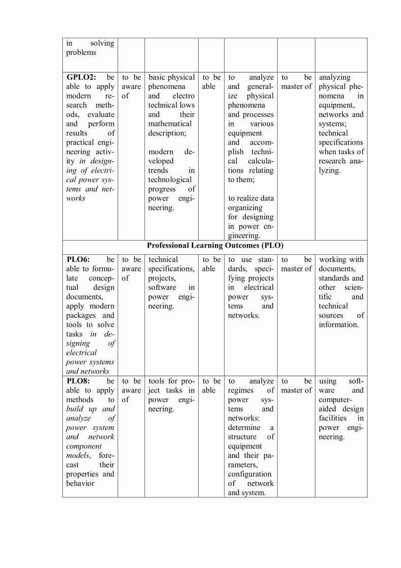
GPLO2: be able to apply modern re-search meth-ods, evaluate and perform results of practical engi-neering activ-ity in design-ing of electri-cal power sys-tems and net-works
to be aware of
basic physical phenomena and electro technical lows and their mathematical description; modern de-veloped trends in technological progress of power engi-neering.
to be able
to analyze and general-ize physical phenomena and processes in various equipment and accom-plish techni-cal calcula-tions relating to them; to realize data organizing for designing in power en-gineering.
to be master of
analyzing physical phe-nomena in equipment, networks and systems; technical specifications when tasks of research ana-lyzing.
Professional Learning Outcomes (PLO)
PLO6: be able to formu-late concep-tual design documents, apply modern packages and tools to solve tasks in de-signing of electrical power systems and networks
to be aware of
technical specifications, projects, software in power engi-neering.
to be able
to use stan-dards, speci-fying projects in electrical power sys-tems and networks.
to be master of
working with documents, standards and other scien-tific and technical sources of information.
PLO8: be able to apply methods to build up and analyze of power system and network component models, fore-cast their properties and behavior
to be aware of
tools for pro-ject tasks in power engi-neering.
to be able
to analyze regimes of power sys-tems and networks: determine a structure of equipment and their pa-rameters, configuration of network and system.
to be master of
using soft-ware and computer-aided design facilities in power engi-neering.

PLO9: be able to choose modern com-mercial equip-ment and de-sign new elec-trical network
to be aware of
standard de-vices, units, software used when design new electrical network.
to be able
to provide numerical experiments according to prescribed techniques, to process and analyze re-sults in de-sign new electrical network.
to be master of
working with software for designing new electri-cal network.
As the consequence of mastering course “Designing electrical power sys-
tems and networks”, students must achieve the following results: Table 2
Planned course learning outcomes
No. Result CCLO1 be able to abstract thinking, generalization, evaluation, classifica-
tion, forecasting for power system and network design CCLO3 be able to personal development and fulfillment, using creativity GPLO1 be able to formulate goals and problems in the area of electrical
power and electrical engineering project, determine priorities in solving problems
GPLO2 be able to apply modern research methods, evaluate and perform re-sults of practical engineering activity in designing of electrical power systems and networks
PLO6 be able to formulate conceptual design documents, apply modern packages and tools to solve tasks in designing of electrical power systems and network
PLO8 be able to apply methods to build up and analyze of power system and network component models, forecast their properties and behav-ior
PLO9 be able to choose modern commercial equipment and design new electrical network
4. Course structure and contents
Section 1. Fundamentals of Power Systems and Networks
Construction design includes the structural design of each network compo-
nent taking account of the various materials available. The object of this section is to introduce those factors which should be taken into account when designing net-works. The emphasis will be on general guidelines in this section. Later sections

are devoted to more detailed considerations of technical aspects and specific engi-neering topics.
Types of academic activity: Lectures: (4 hours) 1. Terms and definitions. Reliability theory and consumer categorization. Network configurations: high-voltage networks and medium-voltage networks. 2. Data for network design and basic approaches for network planning. Nominal voltage level, voltage standards and choice of network voltage. Load data: load-monitoring measurements; load analysis; load curves. Seminars: (8 hours) 1. Basic principles for power flow calculations. 2. Data setting up and planning of network configurations. 3. Power flow calculations in radial and mesh networks. Application of the mo-ment equation.
Section 2. Overhead Lines
Along streets, alleys, through woods, and in backyards, many of lines that feed customers are overhead structures. Because overhead lines are exposed to trees and animals, to wind and lightning, and to cars and kites, they are a critical component in the reliability of networks. This section discusses many of the key electrical considerations of overhead lines: conductor characteristics, impedances, ampacity, and other issues.
Types of academic activity:
Lectures: (4 hours) 1. Conductor typical construction and data. Equivalent circuits of overhead lines. 2. Calculation of equivalent circuits parameters. Power losses in transmission lines. Seminars: (4 hours) 1. Calculation of transmission line equivalent circuit parameters and losses. 2. Conductor cross-section selection. Ampacity, mechanical strength and cor-rosion.
Section 3. AC Transformers and Autotransformers
AC transformers and autotransformers are one of the keys to allowing wide-spread transmission and distribution of electric power. They efficiently convert electricity to higher voltage for long distance transmission and step down to low voltages suitable for customer usage. This section is intended to provide the infor-

mation on the construction and operating characteristics of AC transformers and autotransformers.
Types of academic activity:
Lectures: (4 hours) 1. General information about substation transformers and autotransformers. Equivalent circuit of transformers and autotransformers. 2. Loadings. Power losses in transformers and autotransformers. Transformer and autotransformer selection when designing. Seminars: (2 hours) 1. Calculation of transformer and autotransformer equivalent circuit parame-ters and losses. Selection and checking of transformers and autotransformers.
Section 4. Power flows analysis
This section devotes to power flow analysis which is concerned with de-scribing the operating state of a power system or network, by which it means a network of lines, transformers and loads that could represent an area. Given certain known quantities – typically, the amount of power generated and consumed at dif-ferent locations – power flow analysis allows one to determine other quantities. The most important of these quantities are the voltages at locations throughout the system or networks, which, for alternating current, consist of both a magnitude and a time element or phase angle. Once the voltages are known, the currents flowing through every link can be calculated. Thus the name power flow or load flow, as it is often called in the industry: given the amount of power delivered and where it comes from, power flow analysis tells us how it flows to its destination. In order to find out what the voltage or current at any given point will be, we should in effect simulate a system or network. Historically, such simulations were accomplished through an actual miniature model of the power system or network in use.
Types of academic activity:
Lectures: (2 hours) 1. Types of regimes. Network representation. Types of buses. Seminars: (2 hours) 1. Balancing real and reactive power. Analyses of current flows through every link and voltage levels in every node. Laboratory works: (8 hours) 1. Construction of the radial network digital model in software «Power System Simulator for Engineers». Calculation and analysis of load-peak regime. 2. Construction of the mesh network digital model in software package «Power System Simulator for Engineers» Calculation and analysis of load-peak regime.
Section 5. Voltage regulation

One of a utility’s core responsibilities is to deliver voltage to customers
within a suitable range, so utilities must regulate the voltage. Primary and secon-dary voltage drop can be allocated as necessary along the network to provide end users with suitable voltage. Voltage regulators – in the substation or on feeders – can adjust primary voltage. This section discusses voltage regulators and regulation techniques.
Types of academic activity:
Lectures: (2 hours) 1. Voltage drop. Regulation techniques. Voltage regulation and regulators. Seminars: (4 hours) 1. Application of tap-changing transformers to transmission systems. Distribu-tion system voltage regulation. Relationship between power losses and voltage drop. Laboratory works: (8 hours) 1. Practical realization of voltage regulation in consumer terminal points in the radial network. 2. Practical realization of voltage regulation in consumer terminal points in the mesh network.
Section 6. Control of active power and reactive power
This section examines control of active power and reactive power by consid-ering the system as an entity. In addition, the characteristics and modeling of equipment used are described. The flows of active power and reactive power in a network are independent each other and are influenced by different control actions. Hence, they may be studied separately. Active power control is closely related to frequency control and reactive power control s closely related to voltage control.
Types of academic activity:
Lectures: (4 hours) 1. Fundamentals of speed governing. Generator response to load change. Load response to frequency deviation. Control of generating unit power output. 2. Production and absorption of reactive power. Methods of voltage control. Compensation equipment: shunt reactors; shunt capacitors; series capacitors. Seminars: (2 hours) 1. Composite regulating characteristics of power systems. Laboratory works: (8 hours) 1. Application of compensation equipment in the radial network. 2. Application of compensation equipment in the mesh network.

Section 7. Substation engineering
The construction of new substations and the expansion of existing facilities
are commonplace projects. However, due to the complexity, very few utility em-ployees are familiar with the complete process that allows these projects to be suc-cessfully completed. This section attempts to highlight the major issues associated with the construction substations, and provide a basic understanding of the types of issues that must be addressed during this process.
Types of academic activity:
Lectures: (4 hours) 1. How a substation happens: background; needs determination; traditional and innovative substation design. 2. High-voltage substation: site location; design philosophy; mesh-type substa-tions; single and double-busbar arrangement. Medium-voltage substations. Seminars: (10 hours) 1. High-voltage switching equipment: ambient conditions; disconnect switches; load-break switches; circuit switches; circuit breakers; gas-insulated substations. 2. Substation integration and automation: definitions and terminology; open systems; architecture functional data paths substation; integration and automation system functional architecture; new vs. existing substations; equipment condition monitoring. 3. Substation Integration and Automation: technical issues; system responsi-bilities; system architecture; substation host processor; substation local area net-work; user interface; communication interfaces; data warehouse. Laboratory works: (8 hours) 1. Drawing total radial and mesh networks according to standard by software “Visio”.
Studying course “Designing of electrical power systems and networks” im-plies the use of the following training technologies:
Table 3 Methods and forms of training process organization
Forms of training proc-ess organization
Methods
Lectures Lab. work
Seminars Training, Master class
SGW Team
project
IT methods
X X X
Teamwork
X
Experience-based train- X

ing Advanced self-guided work
X X
Projective method X X Search method X X X X
6. Organization and training materials for students’ self-guided work
6.1. Types and forms of self-guided work
Students’ self-guided work includes everyday and creative problem-oriented
self-guided work (SGW). Everyday self-guided work is focused on extending and reinforcing students’
knowledge, developing practical skills and includes: working with lecture materials, looking for and over viewing literature and electronic sources of information in compliance with an individually predeter-mined course problem; performing home tasks; getting prepared for laboratory work and seminars; getting prepared for examination.
Creative self-guided work includes:
looking for, analyzing, structuring and presenting information; performing calculation; preparing the project.
6.2. Self-guided work contents under the course
Topics to be covered by students individually: modern overhead line construction; phasor diagram application for analysis of line regime; harmonics in power networks; frequency and active power regulation in power systems; modern high-voltage underground cables.
Topics of term projects: application of software “Visio” to design networks.
Topics covered on Internet simulators: application of software package “Power System Simulator for Engineers” for analysis of maximum allowed power flow; application of software “Matlab Simulink” for regime calculation and analy-sis.
6.3. Control self-guided work

The results of self-guided work are to be assessed in the following way: defending laboratory works; presentation and defending project; survey on seminars. The following should be used for self-guided work: materials on professor’s per-sonal website: http://portal.tpu.ru/SHARED/b/BATSEVAN.
7. Means of current and interim assessment of course learning outcomes
Course learning outcomes are to be assessed by means of the following con-
trol procedures: Control procedures Course learning outcomes
Defending laboratory works PLO6, PLO8, PLO9 Presentation and defending project CCLO1, CCLO3, GPLO1,
GPLO2, PLO6, PLO8, PLO9 Survey on seminars and solving tasks CCLO3, GPLO1, PLO6.
The following assessment tools are meant for assessing the course learning outcomes as part of control procedures: control questions to be asked during performance and defense of laboratory work; control questions to be asked during practical exercises; questions to be asked during examination.
Example of past paper The instruction: In tasks A1 – A10 you must choose only one correct answer and write tick ٧ on your blank. Every correct answer is assessed in 4 points. А1 Electrical installation for energy reception, transformation and distribution is
1. Power network 2. Substation 3. Busbar 4. Overhead line
А2 The frequency deviation in power system will take place when 1. changing voltage on generator terminals 2. changing power of stations and loads consistently 3. changing power of loads but power of stations is constant 4. changing power of stations but power of loads is constant
А3 In power systems the main source of reactive power is

1. Power station generators 2. Compensation equipment 3. Charge capacity of transmission lines 4. Storage batteries
А4 Standard power of an autotransformer if it nominal power is Snom=200 MVA and correspondence of winding nominal voltage is 220/110/10, equals
1. 100 MVA 2. 150 MVA 3. 200 MVA 4. 400 MVA
А5 If condensers in capacitor banks are Y-connected that power of capacitor banks equals
1. 23U C 2. 21 3 U C 3. 2U C 4. 23U C
А6 In practice, an overhead line 110 kV and above, with distance before 400 km can be presented as
1. T-type equivalent circuit 2. P- type equivalent circuit 3. Y- type equivalent circuit 4. G- type equivalent circuit
А7 Power flows on main branches of mesh network can be calculated on the basis of
1. Kirchhoff’s voltage law 2. Kirchhoff’s current law 3. Ohm’s low 4. Energy conservation low
А8 Conductor cross-section can be calculated by formula 1. nom
ecec
USj
2. maxec
ec
ISj
3. ecec
max
jSI
4. maxec
ec
PSj
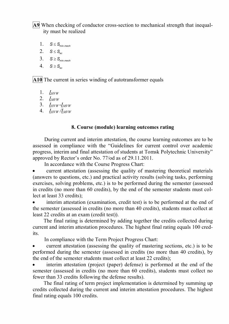
А9 When checking of conductor cross-section to mechanical strength that inequal-ity must be realized
1. min.mechS S 2. ecS S 3. min.mechS S 4. ecS S
А10 The current in series winding of autotransformer equals
1. IHVW 2. IMVW 3. IHVW -IMVW 4. IHVW /IMVW
8. Course (module) learning outcomes rating
During current and interim attestation, the course learning outcomes are to be
assessed in compliance with the “Guidelines for current control over academic progress, interim and final attestation of students at Tomsk Polytechnic University” approved by Rector’s order No. 77/od as of 29.11.2011.
In accordance with the Course Progress Chart: current attestation (assessing the quality of mastering theoretical materials (answers to questions, etc.) and practical activity results (solving tasks, performing exercises, solving problems, etc.) is to be performed during the semester (assessed in credits (no more than 60 credits), by the end of the semester students must col-lect at least 33 credits); interim attestation (examination, credit test) is to be performed at the end of the semester (assessed in credits (no more than 40 credits), students must collect at least 22 credits at an exam (credit test)).
The final rating is determined by adding together the credits collected during current and interim attestation procedures. The highest final rating equals 100 cred-its.
In compliance with the Term Project Progress Chart: current attestation (assessing the quality of mastering sections, etc.) is to be performed during the semester (assessed in credits (no more than 40 credits), by the end of the semester students must collect at least 22 credits); interim attestation (project (paper) defense) is performed at the end of the semester (assessed in credits (no more than 60 credits), students must collect no fewer than 33 credits following the defense results).
The final rating of term project implementation is determined by summing up credits collected during the current and interim attestation procedures. The highest final rating equals 100 credits.

Project “Designing 220/110 kV Radial and Mesh
Power Networks” Sections of the project:
Preface Section 1. Power network topology 1.1. Data for network design 1.2. Network planning 1.3. Tentative calculations: load powers, line length according to scale, power flows without losses 1.4. Choice of nominal voltage 1.5. Selection of conductor cross-section 1.6. Checking conductor cross-section according to ampacity, mechanical strength and corrosion 1.7. Selection of transformers and autotransformers on substations 1.8. Design equivalent circuit for radial and mesh networks 1.9. Calculation of line, transformers and autotransformers equivalent circuit pa-rameters Section 2. Calculation and analysis of load-peak regime 2.1. Analyses of current and power flows through every link and voltage levels in every node 2.2. Voltage regulation 2.3. Selection of compensator equipment Section 3. Drawing total radial and mesh networks according to standard by software “Visio” References
9. Courseware Primary literature: 1. T.A. Short, Electric Power Distribution Equipment and Systems. – CRC Press Taylor and Francis Group, 2007. – 312 p. 2. Electric Power Substation Engineering. Edited by John D. McDonald. – CRC Press LLC, 2003. – 287 p. 3. Alexandra von Meier, Electric Power Systems. A conceptual Introduction. – A John Wiley and Sons, Inc., Publication, 2006. – 328 p. Supplementary literature: 1. Electric Power Generation, Transmission and Distribution. Second Edition. Electric Power Engineering Handbook. Edited by Leonard L. Grigsby. – CRC Press Taylor and Francis Group, 2007. – 500 p. 2. P. Kundur, Power System Stability and Control. McGraw-Hill, Inc., 1994, 1176 p. Internet resources:

1. Power Delivery, IEEE Transactions on Available at: http://ieeexplore.ieee.org /xpl/RecentIssue.jsp?punumber=61 (accessed 27th April 2015).
Software used: 1. Grid Analysis Tool. Available at: https://w3.usa.siemens.com/smartgrid /us/en/transmission-grid/products/grid-analysis-tools/transmission-system-planning /Pages/University-Order.aspx (accessed 27th April 2015). 2. RastrWin Software package. Available at: http://www.rastrwin.ru/en/ (accessed 27th April 2015).
10. Facilities required for the course
List the facilities required for the course: technical aids, laboratory equipment, etc. No. Name (computer classrooms, university laboratories, equipment) Building, rooms,
number of installa-tions
1 Computers Intel Core 2 Duo E4600 – 10 units; Licensed software.
Block 8, Room 221
2 Room for lectures and seminars. Seating capacity 15 units.
Block 8, Room 331
The syllabus is developed in compliance with the Primary Curriculum Standard of TPU in accordance with the requirements of the Federal State Educational Standard for the training field Electrical Power and Electrical Engineering and profile Design and Control of Smart Power Systems.
The syllabus is approved at the meeting of Power Networks and Power En-
gineering Department Author ____________________Natalia L. Batseva Reviewer Head of the primary curriculum _________________ Anton V. Prokhorov