A Rule-Based Control for Fuel-Efficient Automotive Air Conditioning Systems
8
Abstract In a conventional passenger vehicle, the AC system is the largest ancillary load. This paper proposes a novel control strategy to reduce the energy consumption of the air conditioning system of a conventional passenger car. The problem of reducing the parasitic load of the AC system is first approached as a multi-objective optimization problem. Starting from a validated control-oriented model of an automotive AC system, an optimization problem is formalized to achieve the best possible fuel economy over a regulatory driving cycle, while guaranteeing the passenger comfort in terms of cabin temperature and reduce the wear of the components. To complete the formulation of the problem, a set of constraints on the pressure in the heat exchanger are defined to guarantee the safe operation of the system. The Dynamic Programming (DP), a numerical optimization technique, is then used to obtain the optimal solution in form of a control sequence over a prescribed driving cycle. The solution of the DP is analyzed with the scope of understanding the system optimal behavior and extracting rules to mimic the response of the DP but in a forward-looking implementation. The analysis of the global optimal solution allows for the synthesis of a sub-optimal rule-base control, which is then implemented and verified on a test vehicle. Introduction In response to the increasingly stringent mandates for CO 2 reduction, the automotive industry is striving to find solutions that lead to fuel economy improvements. While significant progress has been made in enhancing the efficiency of engines and transmissions, mitigating the power demand of vehicle ancillary loads is a promising and cost- effective way to reduce fuel consumption and emissions [1, 2, 3]. The air conditioning (AC) system is likely the largest ancillary load in a passenger car, with a significant impact on the overall fuel economy of the vehicle. Previous studies have estimated that the use of the AC system can increase the fuel consumption of up to 20% [4, 5, 6]. For this reason, EPA introduced in the 2007 the SC03 Supplemental Federal Test Procedure for fuel economy certification that requires the use of the AC system. In this sense, significant research and development has been recently done in reducing the parasitic load of automotive AC systems, through system downsizing, recuperative devices, or other means [5, 6]. In conjunction with design improvements, system integration and control play a crucial role in optimizing the energy consumption of automotive AC systems. The control strategies currently in production prioritize the cabin comfort requirements [6], while the power consumption of the AC compressor tends to be an afterthought, hence foregoing many potential fuel economy benefits that could be otherwise achieved [1, 5]. On the other hand, designing a control strategy that jointly optimizes for cabin comfort and power consumption is significantly challenging, due to the complexity of considering the thermodynamic properties of the refrigerant and the transient behavior induced by the heat exchangers. Such complexity requires the use of nonlinear models, and multi-objective optimization methods, hardly justifiable for the control of an ancillary load. In this framework, this paper presents a novel approach for the optimization of the AC system based on optimal control theory. First, using a nonlinear control-oriented model of the AC system, an optimization problem is formulated and solved using Dynamic Programming. The solution obtained represents the global optimal solution and it is used in the paper to assess the potential fuel economy savings over a prescribed duty cycle. Then, a complete analysis of the DP solution has been performed considering different driving cycles. This step allowed for the synthesis of a sub-optimal solution that can be implemented online. The obtained rule-based controller has been tested and calibrated in simulation first and then implemented on a vehicle. Experimental results show that his approach leads to an improvement in fuel economy while maintaining the cabin comfort and the control effort unchanged compared to a production controller. A Rule-Based Control for Fuel-Efficient Automotive Air Conditioning Systems 2015-01-0366 Published 04/14/2015 Cristian Rostiti, Stephanie Stockar, and Marcello Canova Ohio State University CITATION: Rostiti, C., Stockar, S., and Canova, M., "A Rule-Based Control for Fuel-Efficient Automotive Air Conditioning Systems," SAE Technical Paper 2015-01-0366, 2015, doi:10.4271/2015-01-0366. Copyright © 2015 SAE International Downloaded from SAE International by Ohio State University Center for Automotive Research, Wednesday, September 02, 2015
Transcript of A Rule-Based Control for Fuel-Efficient Automotive Air Conditioning Systems
AbstractIn a conventional passenger vehicle, the AC system is the largest ancillary load. This paper proposes a novel control strategy to reduce the energy consumption of the air conditioning system of a conventional passenger car. The problem of reducing the parasitic load of the AC system is first approached as a multi-objective optimization problem. Starting from a validated control-oriented model of an automotive AC system, an optimization problem is formalized to achieve the best possible fuel economy over a regulatory driving cycle, while guaranteeing the passenger comfort in terms of cabin temperature and reduce the wear of the components. To complete the formulation of the problem, a set of constraints on the pressure in the heat exchanger are defined to guarantee the safe operation of the system. The Dynamic Programming (DP), a numerical optimization technique, is then used to obtain the optimal solution in form of a control sequence over a prescribed driving cycle. The solution of the DP is analyzed with the scope of understanding the system optimal behavior and extracting rules to mimic the response of the DP but in a forward-looking implementation. The analysis of the global optimal solution allows for the synthesis of a sub-optimal rule-base control, which is then implemented and verified on a test vehicle.
IntroductionIn response to the increasingly stringent mandates for CO2 reduction, the automotive industry is striving to find solutions that lead to fuel economy improvements. While significant progress has been made in enhancing the efficiency of engines and transmissions, mitigating the power demand of vehicle ancillary loads is a promising and cost-effective way to reduce fuel consumption and emissions [1, 2, 3].
The air conditioning (AC) system is likely the largest ancillary load in a passenger car, with a significant impact on the overall fuel economy of the vehicle. Previous studies have estimated that the use of the AC system can increase the fuel consumption of up to 20% [4,
5, 6]. For this reason, EPA introduced in the 2007 the SC03 Supplemental Federal Test Procedure for fuel economy certification that requires the use of the AC system. In this sense, significant research and development has been recently done in reducing the parasitic load of automotive AC systems, through system downsizing, recuperative devices, or other means [5, 6].
In conjunction with design improvements, system integration and control play a crucial role in optimizing the energy consumption of automotive AC systems. The control strategies currently in production prioritize the cabin comfort requirements [6], while the power consumption of the AC compressor tends to be an afterthought, hence foregoing many potential fuel economy benefits that could be otherwise achieved [1, 5]. On the other hand, designing a control strategy that jointly optimizes for cabin comfort and power consumption is significantly challenging, due to the complexity of considering the thermodynamic properties of the refrigerant and the transient behavior induced by the heat exchangers. Such complexity requires the use of nonlinear models, and multi-objective optimization methods, hardly justifiable for the control of an ancillary load.
In this framework, this paper presents a novel approach for the optimization of the AC system based on optimal control theory. First, using a nonlinear control-oriented model of the AC system, an optimization problem is formulated and solved using Dynamic Programming. The solution obtained represents the global optimal solution and it is used in the paper to assess the potential fuel economy savings over a prescribed duty cycle. Then, a complete analysis of the DP solution has been performed considering different driving cycles. This step allowed for the synthesis of a sub-optimal solution that can be implemented online. The obtained rule-based controller has been tested and calibrated in simulation first and then implemented on a vehicle. Experimental results show that his approach leads to an improvement in fuel economy while maintaining the cabin comfort and the control effort unchanged compared to a production controller.
A Rule-Based Control for Fuel-Efficient Automotive Air Conditioning Systems
2015-01-0366
Published 04/14/2015
Cristian Rostiti, Stephanie Stockar, and Marcello CanovaOhio State University
CITATION: Rostiti, C., Stockar, S., and Canova, M., "A Rule-Based Control for Fuel-Efficient Automotive Air Conditioning Systems," SAE Technical Paper 2015-01-0366, 2015, doi:10.4271/2015-01-0366.
Copyright © 2015 SAE International
Downloaded from SAE International by Ohio State University Center for Automotive Research, Wednesday, September 02, 2015

This paper is organized as follows. First, the system and the model equations are presented together with the definition of the control problem. Then, the rule extraction procedure is described and the simulation results are shown. Finally, the novel control strategy is evaluated on the vehicle.
Description of the System and ModelThis study is conducted on a conventional automotive air conditioning system based upon a simple vapor compression cycle with R-134a as the working fluid. A schematic of the experimental setup for the vapor compression cycle is shown in Figure 1, illustrating the thermodynamic states and measured signals. The system includes a screw compressor connected to the engine auxiliary belt through an electromagnetic clutch. An ETAS Intecrio ES1000.3 system allows for measuring the relevant system outputs (pressures in the two heat exchangers, clutch state π and engine performance variables), as well as for controlling the clutch.
Figure 1. Schematic of a Typical Automotive AC System.
Overview of the AC ModelThis work is based upon a control-oriented model of the compression refrigeration cycle of the AC system, which was previously developed and validated in [7]. This lumped-parameter model describes the dynamics of the pressure in the evaporator and condenser through an energy balance equation applied to the two heat exchangers.
With reference to the thermodynamic states and notation indicated in Figure 1, the two equations describing the dynamics of the system are given as follows:
(1)
where V is the system volume, p the pressure, T is the temperature, hl is the saturated liquid enthalpy, hg the saturated vapor enthalpy, ρ is the average refrigerant density in the heat exchanger, ṁ the air mass flow rate of refrigerant, Ta,in the inlet air temperature, and γ represents the mean void fraction of the refrigerant. The parameters Ce and Cc represent the heat capacity of the metal masses of the evaporator and condenser, and the subscribe e and c identify the evaporator and
condenser respectively. The thermodynamic properties for the refrigerant are expressed as functions of the pressure and average enthalpy within the two heat exchangers.
A more detailed explanation of the derivation of this model and a validation with experimental data collected on a test vehicle are given in [7].
Analysis of the AC System Transient BehaviorTo better understand the AC system behavior and devise a control algorithm that can be implemented in vehicle, an energy analysis was performed considering the SC03 driving cycle as a case study. The production control strategy tends to operate the AC clutch with a thermostatic approach, wherein the refrigerant loop is controlled based on an upper and lower pressure threshold. Figure 2 shows a portion of the evaporator pressure profile collected from vehicle tests. At t=295s the clutch activates the compressor, which causes a sudden decrease of the evaporator pressure.
Figure 2. Analysis of Response Time of the AC System, with Respect to the Evaporator Pressure (Production Control Strategy).
The time required by the production control strategy to store the maximum amount of energy in the system (namely, allow the evaporator to reach its minimum pressure from its maximum threshold) is typically around 6 seconds. Once the evaporator pressure reaches a lower threshold, the AC clutch is disengaged. The time between two consecutive clutch engagements is around 10 seconds, meaning that the off phase is characterized by a slower dynamics due to the lower heat transfer coefficient in absence of forced refrigerant flow.
It is important to observe that the dynamics associated to the storage of energy in the in the vehicle AC system is generally much faster than a typical deceleration and braking events during a driving cycle.
Moreover, Figure 3 shows that the energy consumed by the compressor to completely pressurize the AC system is about 7.5kJ, which is rather small compared to the negative energy available at the crankshaft during a deceleration event [2, 3, 5].
The faster dynamics and low energy density that characterize the AC system allow one to assume that the evaporator behaves as a short-term energy storage system. Therefore, despite the limited storage capacity, the AC system can be used to store a portion of the vehicle brake energy, and reduce the impact of the AC compressor energy consumption.
Downloaded from SAE International by Ohio State University Center for Automotive Research, Wednesday, September 02, 2015
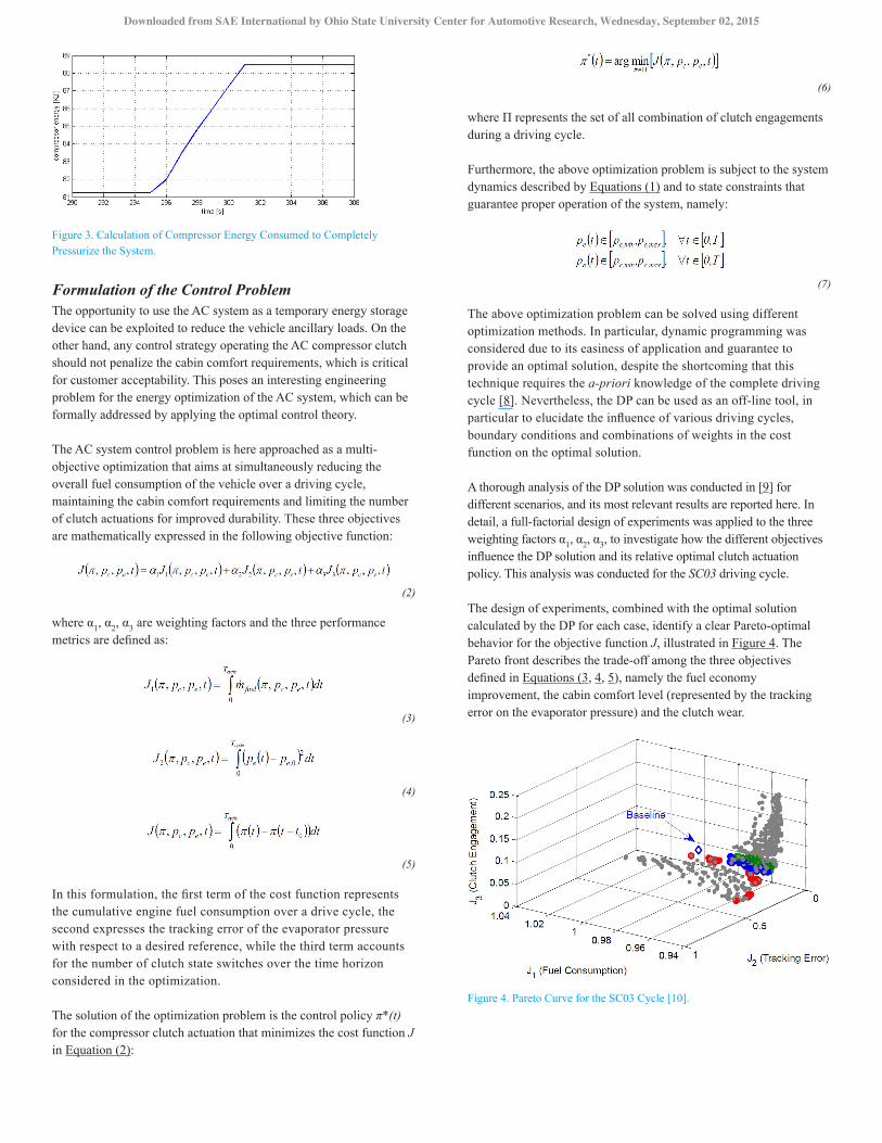
Figure 3. Calculation of Compressor Energy Consumed to Completely Pressurize the System.
Formulation of the Control ProblemThe opportunity to use the AC system as a temporary energy storage device can be exploited to reduce the vehicle ancillary loads. On the other hand, any control strategy operating the AC compressor clutch should not penalize the cabin comfort requirements, which is critical for customer acceptability. This poses an interesting engineering problem for the energy optimization of the AC system, which can be formally addressed by applying the optimal control theory.
The AC system control problem is here approached as a multi-objective optimization that aims at simultaneously reducing the overall fuel consumption of the vehicle over a driving cycle, maintaining the cabin comfort requirements and limiting the number of clutch actuations for improved durability. These three objectives are mathematically expressed in the following objective function:
(2)
where α1, α2, α3 are weighting factors and the three performance metrics are defined as:
(3)
(4)
(5)
In this formulation, the first term of the cost function represents the cumulative engine fuel consumption over a drive cycle, the second expresses the tracking error of the evaporator pressure with respect to a desired reference, while the third term accounts for the number of clutch state switches over the time horizon considered in the optimization.
The solution of the optimization problem is the control policy π*(t) for the compressor clutch actuation that minimizes the cost function J in Equation (2):
(6)
where Π represents the set of all combination of clutch engagements during a driving cycle.
Furthermore, the above optimization problem is subject to the system dynamics described by Equations (1) and to state constraints that guarantee proper operation of the system, namely:
(7)
The above optimization problem can be solved using different optimization methods. In particular, dynamic programming was considered due to its easiness of application and guarantee to provide an optimal solution, despite the shortcoming that this technique requires the a-priori knowledge of the complete driving cycle [8]. Nevertheless, the DP can be used as an off-line tool, in particular to elucidate the influence of various driving cycles, boundary conditions and combinations of weights in the cost function on the optimal solution.
A thorough analysis of the DP solution was conducted in [9] for different scenarios, and its most relevant results are reported here. In detail, a full-factorial design of experiments was applied to the three weighting factors α1, α2, α3, to investigate how the different objectives influence the DP solution and its relative optimal clutch actuation policy. This analysis was conducted for the SC03 driving cycle.
The design of experiments, combined with the optimal solution calculated by the DP for each case, identify a clear Pareto-optimal behavior for the objective function J, illustrated in Figure 4. The Pareto front describes the trade-off among the three objectives defined in Equations (3, 4, 5), namely the fuel economy improvement, the cabin comfort level (represented by the tracking error on the evaporator pressure) and the clutch wear.
Figure 4. Pareto Curve for the SC03 Cycle [10].
Downloaded from SAE International by Ohio State University Center for Automotive Research, Wednesday, September 02, 2015
If a solution lies on the Pareto front, no further improvement of a single objective can be attained without penalizing the other two. As evidenced in Figure 4, an improvement in fuel economy can be obtained only at the expense of the tracking error on the evaporator pressure, meaning that the cabin comfort will be penalized.
In addition to the Pareto front, Figure 4 indicates the location of the point corresponding to the “Baseline” condition, namely the production clutch control strategy measured on the test vehicle for the SC03 cycle. It is immediately evident that this strategy does not lie on the Pareto curve, and hence there is a concrete opportunity for improving the vehicle fuel economy without penalizing the cabin comfort requirements.
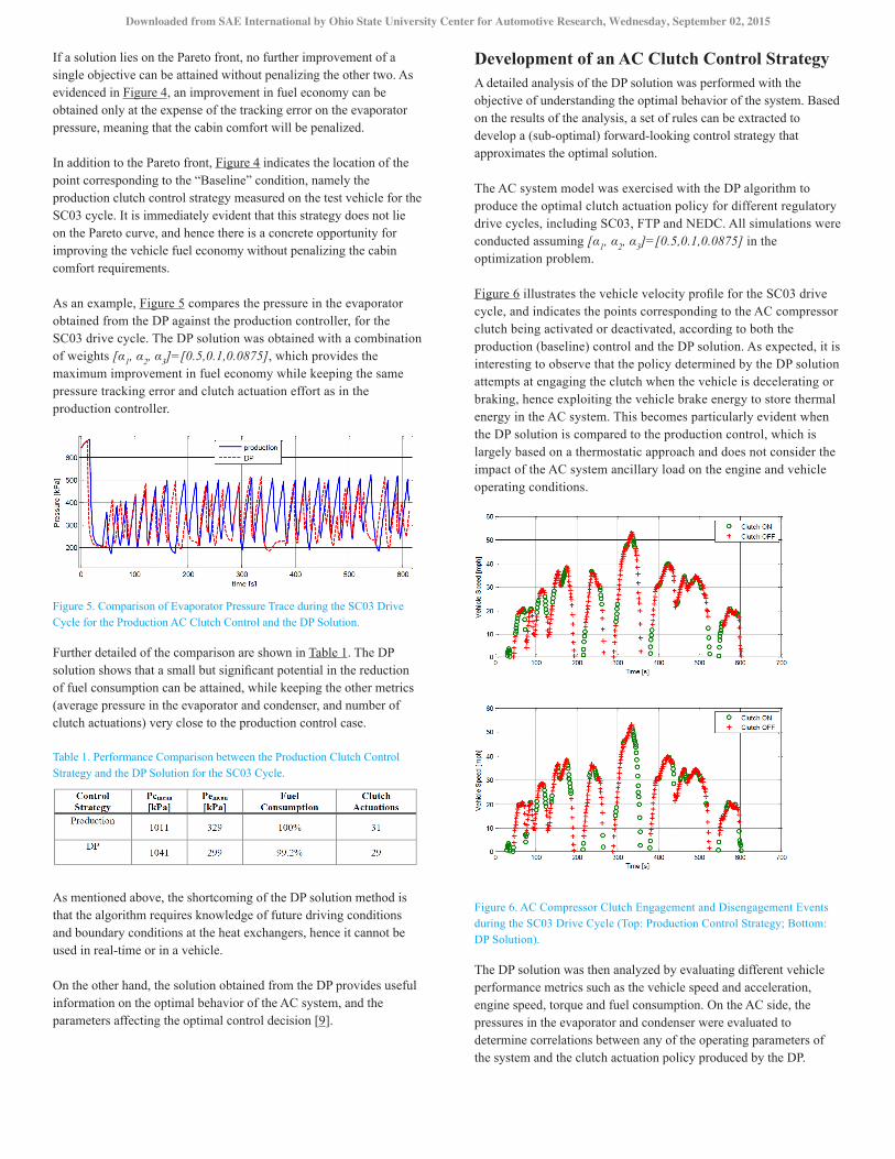
As an example, Figure 5 compares the pressure in the evaporator obtained from the DP against the production controller, for the SC03 drive cycle. The DP solution was obtained with a combination of weights [α1, α2, α3]=[0.5,0.1,0.0875], which provides the maximum improvement in fuel economy while keeping the same pressure tracking error and clutch actuation effort as in the production controller.
Figure 5. Comparison of Evaporator Pressure Trace during the SC03 Drive Cycle for the Production AC Clutch Control and the DP Solution.
Further detailed of the comparison are shown in Table 1. The DP solution shows that a small but significant potential in the reduction of fuel consumption can be attained, while keeping the other metrics (average pressure in the evaporator and condenser, and number of clutch actuations) very close to the production control case.
Table 1. Performance Comparison between the Production Clutch Control Strategy and the DP Solution for the SC03 Cycle.
As mentioned above, the shortcoming of the DP solution method is that the algorithm requires knowledge of future driving conditions and boundary conditions at the heat exchangers, hence it cannot be used in real-time or in a vehicle.
On the other hand, the solution obtained from the DP provides useful information on the optimal behavior of the AC system, and the parameters affecting the optimal control decision [9].
Development of an AC Clutch Control StrategyA detailed analysis of the DP solution was performed with the objective of understanding the optimal behavior of the system. Based on the results of the analysis, a set of rules can be extracted to develop a (sub-optimal) forward-looking control strategy that approximates the optimal solution.
The AC system model was exercised with the DP algorithm to produce the optimal clutch actuation policy for different regulatory drive cycles, including SC03, FTP and NEDC. All simulations were conducted assuming [α1, α2, α3]=[0.5,0.1,0.0875] in the optimization problem.
Figure 6 illustrates the vehicle velocity profile for the SC03 drive cycle, and indicates the points corresponding to the AC compressor clutch being activated or deactivated, according to both the production (baseline) control and the DP solution. As expected, it is interesting to observe that the policy determined by the DP solution attempts at engaging the clutch when the vehicle is decelerating or braking, hence exploiting the vehicle brake energy to store thermal energy in the AC system. This becomes particularly evident when the DP solution is compared to the production control, which is largely based on a thermostatic approach and does not consider the impact of the AC system ancillary load on the engine and vehicle operating conditions.
Figure 6. AC Compressor Clutch Engagement and Disengagement Events during the SC03 Drive Cycle (Top: Production Control Strategy; Bottom: DP Solution).
The DP solution was then analyzed by evaluating different vehicle performance metrics such as the vehicle speed and acceleration, engine speed, torque and fuel consumption. On the AC side, the pressures in the evaporator and condenser were evaluated to determine correlations between any of the operating parameters of the system and the clutch actuation policy produced by the DP.
Downloaded from SAE International by Ohio State University Center for Automotive Research, Wednesday, September 02, 2015

Out of the different metrics evaluated in this analysis, it was found that the optimal clutch actuation policy is significantly influenced by the evaporator pressure and the engine torque. To this extent, Figure 7 represents the clutch engagement and disengagement events commanded by the DP during the SC03 drive cycle, in relation with the aforementioned metrics.
Figure 7. Optimal AC Compressor Clutch Engagement and Disengagement Events in Relation with Evaporator Pressure and Engine Torque (SC03 Cycle).
The results indicate that there is a correlation between the optimal decision, the engine torque and the evaporator pressure. Intuitively, the DP solution attempts at keeping the pressure around a certain set point by engaging the clutch when the pressure in the evaporator drops below a threshold. At the same time, the DP exploits the negative engine torque region to harvest energy from the crankshaft.
Formalization of a Rule-Based ControllerThe characteristic behavior that emerges from the DP solution allows for exploiting the energy from the crankshaft when available and hence reducing the overall parasitic load on the engine over the drive cycle. The DP solution is therefore leveraged to extract a set of rules to control the AC clutch in relation with not only the evaporator pressure, but also the engine torque.
Figure 8. Definition of Thresholds for the AC System Control.
Using the notation in Figure 8, the proposed control strategy consists of three rules:
1. Engage the compressor clutch (Clutch ON) when the engine torque is below a minimum threshold (Tmin); OR
2. Engage the compressor clutch (Clutch ON) when the evaporator pressure rises above a maximum threshold (Pmax); AND
3. Disengage the AC compressor clutch when the evaporator pressure drops below a minimum threshold (Pmin).
The first rule ensures that some of the energy is harvested at the crankshaft during decelerations for the powering the AC compressor. Ideally, the torque threshold that defines this rule should be placed in
correspondence of the zero torque line. However, to avoid unwanted clutch engagements that may result from errors in the estimation of the engine torque near zero crossing conditions, the threshold should be set to slightly negative values. Moreover, this condition contributes to limiting the clutch chattering behavior and, since the total energy required for a full pressurization of the AC system is low, only negligible or marginal penalties on the fuel economy performance of the rule base controller should be expected.
The second and third rules determine the decision on the clutch actuation solely based on the current evaporator pressure. In this sense, these rules are in principle similar to the production controller case. However, a dead-band must be introduced to avoid rapid clutch transitions when the evaporator pressure becomes close to the reference value. The presence of a dead-band requires the definition of two thresholds in place of one, hence duplicating the number of tuning parameters. On the other hand, it greatly improves the smoothness of the clutch actuation and reduces the component wear.
The size of this dead-band strongly affects the performance of the controller and particularly impacts the ability of the system to maintain the evaporator pressure close to its reference value. A tighter band ensures a good tracking of the desired pressure, but causes the number of clutch actuations to increase and reduces the benefits on fuel economy. To ensure a safe operation of the compressor clutch, the rules have been implemented such that, in case of a conflicting decision where two criteria are met at the same time, the priority is assigned to the tracking of the desired pressure.
It is clear that, although the structure of the rule-based controller is relatively simple, the calibration of its parameters is key to obtain a forward-looking strategy that performs close to the DP solution.
To further reduce the chattering behavior induced by the on/off control of the compressor clutch, a hysteresis model was applied to the thresholds in the rule-base controller. Specifically, each of the three thresholds is subdivided into two bounds, for instance Tmin is implemented as Tmin+ and Tmin-. Similarly, Pmin+ and Pmin- are defined as the upper and lower bound of the hysteresis associated to the Clutch ON decision and Pmax+ and Pmax- are introduced for the Clutch OFF command.
The aforementioned rule-based control strategy is characterized by 6 calibration parameters. As mentioned above, the tuning of these parameters is particularly challenging because of the complex nature of the optimization problem. To find a set of parameters that ensures a good trade-off among the three objectives, a preliminary tuning was performed in simulation considering the SC03 cycle, using the energy-based model of the AC system as a virtual system. Once a first set of parameters is found, the strategy was implemented on the test vehicle for further tuning and performance evaluation.
Vehicle Implementation, Results and AnalysisThe rule-based controller was implemented on an ETAS Intecrio ES1000.3 rapid-prototyping system, and the experimental tests for tuning and verification were performed on a 2011 Chrysler Town & Country Minivan on a vehicle chassis dynamometer located in a temperature-controlled room.
Downloaded from SAE International by Ohio State University Center for Automotive Research, Wednesday, September 02, 2015

Figure 9. Overview of the Experimental Setup for Testing of the Rule-Based AC Clutch Control Strategy.
Figure 9 illustrates the basic architecture of the vehicle setup and outlines the procedure followed for data acquisition and evaluation of the controller performance. The rule-based control strategy requires the engine torque (from the ECU) and the measured pressure in the evaporator as inputs. The procedure for the evaluating the results requires the experimental data outlined in figure. The engine speed and torque are obtained directly from ECU-readings, while the clutch signal is obtained by measuring the actuator current.
While the tracking error on the evaporator pressure and the number of clutch engagements during a driving cycles can be directly calculated from the vehicle data, a more complex procedure is required to estimate the vehicle fuel consumption in a way that limits the uncertainties induced by variability of the driving and environmental conditions.
Specifically, the fuel consumption is calculated starting from the measured evaporator and condenser pressure, and from the measured engine crankshaft speed. These signals are used to calculate the power and torque absorbed by the AC compressor, and added as a parasitic load to the engine torque. Finally, the resulting torque and engine speed are used to compute the fuel economy for a given drive cycle, based upon a look-up table of the engine fuel consumption.
To provide a consistent comparison, the above procedure is applied to the experimental results collected for both the production controller and the rule-based strategy. Several experimental tests were conducted for tuning the rule-based controller, and for comparing its performance against the production control strategy.
Experimental tests were performed considering different settings for the vehicle HVAC control system corresponding to low, medium and full:
• Low: desired cabin temperature set to 70F with controlled cabin blower speed;
• Medium: desired cabin temperature set to 66F with controlled cabin blower speed;
• Full: minimum desired cabin temperature with automatic setting for the cabin blower (maximum speed).
For the three scenarios described above, experimental data for two consecutive SC03 driving cycles were collected for each control strategy (production and rule-based). For the rule-based strategy, the parameters were tuned starting from the preliminary values obtained from the simulation study.
The metrics used for the performance evaluation are the same used in the optimal control problem formulation. Specifically, the two strategies are evaluated based on the normalized fuel consumption over the driving cycle, the tracking error of the desired evaporator pressure and number of clutch actuations. The results of the experimental campaign are summarized in Table 2.
Table 2. Summary of Control Strategy Performance for Experimental Tests Conducted on the SC03 Drive Cycle.
The above results are obtained after performing a tuning of the control parameters. With the exception for the test at “Low” HVAC setting, the proposed rule-based control strategy leads to a systematic reduction in the vehicle fuel consumption, compared to the production controller, without significant penalty on the ability to track the reference evaporator pressure. Furthermore, a significant reduction in the frequency of clutch engagements is observed, which has a beneficial effect on the overall vehicle NVH and on the durability of the components.
Since the cabin air temperature at the exit of the evaporator can be converted into an equivalent refrigerant pressure, each of the HVAC settings considered in this study corresponds to a specific desired mean evaporator pressure. To limit the calibration effort of the rule-based control strategy, a regression analysis was performed to identify a correlation between the HVAC setpoints and the optimal control parameters. The results of thisanalysis are shown in Figure 10, where a linear relation is found between the control strategy parameter and the reference mean evaporator pressure.
Figure 10. Correlation Between Rule-Based Control Strategy Parameters and Mean Reference Evaporator Pressure.
Downloaded from SAE International by Ohio State University Center for Automotive Research, Wednesday, September 02, 2015
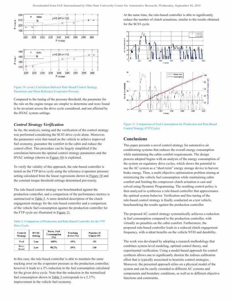
Figure 10. (cont.) Correlation Between Rule-Based Control Strategy Parameters and Mean Reference Evaporator Pressure.
Compared to the tuning of the pressure threshold, the parameter for the rule on the engine torque are simpler to determine and were found to be invariant across the drive cycle considered, and not affected by the HVAC system settings.
Control Strategy VerificationSo far, the analysis, tuning and the verification of the control strategy was performed considering the SC03 drive cycle alone. Moreover, the parameters were fine-tuned on the vehicle to achieve improved fuel economy, guarantee the comfort in the cabin and reduce the control effort. This procedure can be largely simplified if the correlation between the optimal control strategy parameters and the HVAC settings (shown in Figure 10) is exploited.
To verify the validity of this approach, the rule-based controller is tested on the FTP drive cycle using the reference evaporator pressure setting calculated from the linear regressions shown in Figure 10 and the constant torque threshold settings determined previously.
The rule-based control strategy was benchmarked against the production controller, and a comparison of the performance metrics is summarized in Table 3. A more detailed description of the clutch engagement strategy for the rule-based controller and a comparison of the vehicle fuel consumption against the production controller for the FTP cycle are illustrated in Figure 11.
Table 3. Comparison of Production and Rule-Based Controller for the FTP Drive Cycle.
In this case, the rule-based controller is able to maintain the same tracking error on the evaporator pressure as the production controller, however it leads to a 2% reduction in the fuel consumption calculated for the given drive cycle. Note that the reduction in the normalized fuel consumption shown in Table 3 corresponds to a 2.37% improvement in the vehicle fuel economy.
At the same time, the rule-based controller is able to significantly reduce the number of clutch actuations, similar to the results obtained for the SC03 cycle.
Figure 11. Comparison of Fuel Consumption for Production and Rule-Based Control Strategy (FTP Cycle).
ConclusionsThis paper presents a novel control strategy for automotive air conditioning systems that reduces the overall energy consumption while maintaining the cabin comfort requirements. The design process adopted begins with an analysis of the energy consumption of the system on regulatory drive cycles, which shows the potential to use the AC system as a “short-term” energy storage device to harvest brake energy. Then, a multi-objective optimization problem aiming at minimizing the vehicle fuel consumption while maintaining cabin comfort and limiting the compressor clutch actuation is cast and solved using Dynamic Programming. The resulting control policy is then analyzed to synthesize a rule-based controller that approximates the optimal system behavior. Verification and fine tuning of the rule-based control strategy is finally conducted on a test vehicle, benchmarking the results against the production controller.
The proposed AC control strategy systematically achieves a reduction in fuel consumption compared to the production controller, with virtually no penalties on the cabin comfort. Furthermore, the proposed rule-based controller leads to a reduced clutch engagement frequency, with evident benefits on the vehicle NVH and durability.
The work was developed by adopting a research methodology that combines system-level modeling, optimal control theory, and experimental verification. Using a model-based approach for control synthesis allows one to significantly shorten the tedious calibration effort that is typically associated to heuristic control strategies. Moreover, the presented approach relies on a physical model of the system and can be easily extended to different AC systems and components and boundary conditions, as well as to different objective functions and constraints.
Downloaded from SAE International by Ohio State University Center for Automotive Research, Wednesday, September 02, 2015

Current research is focusing on conducting further vehicle tests to confirm the results presented in this paper. As future work, the proposed approach will be extended to different AC systems, incorporate a cabin thermal model and modify the optimization problem to incorporate the cabin temperature, in place of the tracking error on evaporator pressure.
References1. Lyu, M., Doo, B., and Ku, Y., “A Study of Vehicle Fuel Economy
Improvement Potential by Optimization of the Cooling and Ancillary Systems of a Heavy Duty Engine,” SAE Technical Paper 2007-01-1772, 2007, doi:10.4271/2007-01-1772.
2. Silva C., Marc R., and Farias T., “Analysis and Simulation of Low-Cost Strategies to Reduce Fuel Consumption and Emissions in Conventional Gasoline Light-Duty Vehicles”, Energy Conversion and Management, Vol. 50, No. 2, 2009.
3. Chiara F. and Canova M., “A Review of Energy Consumption, Management and Recovery in Automotive Systems with Considerations on Future Trends”, Proc. Inst. Mech. Eng., Part D: Journal of Automobile Engineering, 2012.
4. Rugh, J., Howland, V., and Anderson, S., “Significant Fuel Savings and Emission Reduction by Improving Vehicle Air Conditioning”. Mobile Air Conditioning Summit, Washington, DC, 2004.
5. Harrison, T., “Air Conditioning System Utilizing Vehicle Waste Energy,” SAE Technical Paper 2009-01-0543, 2009, doi:10.4271/2009-01-0543.
6. Liu J., Zhou H. and Zhou X., “Automotive Air Conditioning System Control - A Survey”, Proc. Of International Conference on Electronic & Mechanical Engineering and Information Technology, 2011.
7. Zhang Q., Canova M.. “Lumped-Parameter Modeling of an Automotive Air Conditioning System for Energy Optimization and Management.” Proc. Of ASME Dynamic Systems and Control Conference, 2013.
8. Bertsekas D., “Dynamic Programming and Optimal Control”, Athena Scientific, Vol. 1, No. 2, 1995.
9. Zhang Q., “Modeling, Energy Optimization and Control of Vapor Compression Refrigeration System for Automotive Applications”, PhD Dissertation, The Ohio State University, 2014.
Contact InformationStephanie StockarCenter for Automotive ResearchThe Ohio State University930 Kinnear RoadColumbus, OH [email protected]
AcknowledgmentsThe authors gratefully acknowledge the U.S. Department of Energy and Chrysler Group, LLC for supporting the research that led to the content of this paper.
Definitions/AbbreviationsDP - Dynamic programming
AC - Air conditioning
π - Clutch command
V - Volume
p - Pressure
T - Temperature
h - Enthalpy
ṁ - Mass flow rate
γ - Mean void fraction of refrigerant
C - Heat capacity
t - Time
HVAC - Heating, ventilating and air conditioning
Tmin - Minimum Torque
The Engineering Meetings Board has approved this paper for publication. It has successfully completed SAE’s peer review process under the supervision of the session organizer. The process requires a minimum of three (3) reviews by industry experts.
All rights reserved. No part of this publication may be reproduced, stored in a retrieval system, or transmitted, in any form or by any means, electronic, mechanical, photocopying, recording, or otherwise, without the prior written permission of SAE International.
Positions and opinions advanced in this paper are those of the author(s) and not necessarily those of SAE International. The author is solely responsible for the content of the paper.
ISSN 0148-7191
http://papers.sae.org/2015-01-0366
Downloaded from SAE International by Ohio State University Center for Automotive Research, Wednesday, September 02, 2015