A review of methods for constructing coastal recreational facilities in Egypt (Red Sea
12
ecological engineering 27 ( 2 0 0 6 ) 1–12 available at www.sciencedirect.com journal homepage: www.elsevier.com/locate/ecoleng Review A review of methods for constructing coastal recreational facilities in Egypt (Red Sea) Omran E. Frihy a,∗ , Ali N. Hassan b , Walid R. El Sayed a , Moheb M. Iskander a , Mohamed Y. Sherif c a Coastal Research Institute, 15 El Pharaana Street, El Shallalat 21514, Alexandria, Egypt b Institute of Environment Studies and Research, Ain Shams University, Cairo, Egypt c Environics Environmental Consulting Firm, Cairo, Egypt article info Article history: Received in revised form 4 November 2005 Accepted 9 November 2005 Keywords: Coral reef Shoreline facilities Natural lagoons Human infringements Water-intake Coastal development planning abstract The Red Sea coast of Egypt has seen major resort facilities created over the last 20 years. Improper designs and non-environmentally friendly sea shore recreation facilities have been constructed by some developers, such as hard structures; earth embankment jetties; digging lagoons and placing landfill, all creating harmful impacts on the coastal ecosys- tem. The impacts of these illegal facilities include changing the depositional-hydrodynamic regime, as a result of blocking littoral currents by protruding structures; creating down-drift erosion to the neighboring beaches, deteriorating water quality and changing the marine biota. Moreover, these actions usually put additional costs on developers either in the form of fines or as direct restoration costs. This study illustrates best practice examples that better interface with the coastal system of the Red Sea. It reports on environmentally friendly solu- tions to deal with problems associated with wide fringing reef, water-intake effluent, rocky and elevated cliff beaches. In addition, it provides alternate solutions for the currently pop- ular “artificial lagoons” proposed by investors. The protective response of pronounced reef features against waves is discussed in relation to implementing central marinas or artificial beaches in the shelter zone of the reef. It shows how tide-induced sea–groundwater inter- action into beach sediment overlaying reef surfaces can be exploited to release brine from artificial lagoons, discharging from local desalination plants, instead of direct discharging into the sea. The lessons learned from this study indicate that detailed shoreline and bathymetric surveys associated with basic hydrodynamic measurements of a coastal area are crucial. They are fundamental in identifying natural beaches and seabed features that could be used, but preserved, for the benefits of coastal development. © 2005 Elsevier B.V. All rights reserved. 1. Introduction The Red Sea coasts of Egypt have been the site of intensive tourism developments over the last 20 years. Most of the Red ∗ Corresponding author. Tel.: +203 5276126; fax: +203 4844614. E-mail address: [email protected] (O.E. Frihy). Sea shoreline is fronted by a discontinuous series of extensive fringed coral reefs up to a maximum of 700 m wide. In some areas, such as Hurghada, these reefs are fronted by a group of barrier islands made up of igneous and metamorphic rocks. 0925-8574/$ – see front matter © 2005 Elsevier B.V. All rights reserved. doi:10.1016/j.ecoleng.2005.11.001
-
Upload
independent -
Category
Documents
-
view
0 -
download
0
Transcript of A review of methods for constructing coastal recreational facilities in Egypt (Red Sea
e c o l o g i c a l e n g i n e e r i n g 2 7 ( 2 0 0 6 ) 1–12
avai lab le at www.sc iencedi rec t .com
journa l homepage: www.e lsev ier .com/ locate /eco leng
Review
A review of methods for constructing coastal recreationalfacilities in Egypt (Red Sea)
Omran E. Frihya,∗, Ali N. Hassanb, Walid R. El Sayeda,Moheb M. Iskandera, Mohamed Y. Sherif c
a Coastal Research Institute, 15 El Pharaana Street, El Shallalat 21514, Alexandria, Egyptb Institute of Environment Studies and Research, Ain Shams University, Cairo, Egyptc Environics Environmental Consulting Firm, Cairo, Egypt
a r t i c l e i n f o
Article history:
Received in revised form 4
November 2005
Accepted 9 November 2005
Keywords:
Coral reef
Shoreline facilities
Natural lagoons
Human infringements
Water-intake
Coastal development planning
a b s t r a c t
The Red Sea coast of Egypt has seen major resort facilities created over the last 20 years.
Improper designs and non-environmentally friendly sea shore recreation facilities have
been constructed by some developers, such as hard structures; earth embankment jetties;
digging lagoons and placing landfill, all creating harmful impacts on the coastal ecosys-
tem. The impacts of these illegal facilities include changing the depositional-hydrodynamic
regime, as a result of blocking littoral currents by protruding structures; creating down-drift
erosion to the neighboring beaches, deteriorating water quality and changing the marine
biota. Moreover, these actions usually put additional costs on developers either in the form
of fines or as direct restoration costs. This study illustrates best practice examples that better
interface with the coastal system of the Red Sea. It reports on environmentally friendly solu-
tions to deal with problems associated with wide fringing reef, water-intake effluent, rocky
and elevated cliff beaches. In addition, it provides alternate solutions for the currently pop-
ular “artificial lagoons” proposed by investors. The protective response of pronounced reef
features against waves is discussed in relation to implementing central marinas or artificial
beaches in the shelter zone of the reef. It shows how tide-induced sea–groundwater inter-
action into beach sediment overlaying reef surfaces can be exploited to release brine from
artificial lagoons, discharging from local desalination plants, instead of direct discharging
into the sea.
The lessons learned from this study indicate that detailed shoreline and bathymetric
surveys associated with basic hydrodynamic measurements of a coastal area are crucial.
in identifying natural beaches and seabed features that could be
r th
Sea shoreline is fronted by a discontinuous series of extensive
They are fundamental
used, but preserved, fo
1. Introduction
The Red Sea coasts of Egypt have been the site of intensivetourism developments over the last 20 years. Most of the Red
∗ Corresponding author. Tel.: +203 5276126; fax: +203 4844614.E-mail address: [email protected] (O.E. Frihy).
0925-8574/$ – see front matter © 2005 Elsevier B.V. All rights reserved.doi:10.1016/j.ecoleng.2005.11.001
e benefits of coastal development.
© 2005 Elsevier B.V. All rights reserved.
fringed coral reefs up to a maximum of 700 m wide. In someareas, such as Hurghada, these reefs are fronted by a group ofbarrier islands made up of igneous and metamorphic rocks.
2 e c o l o g i c a l e n g i n e e r i n g 2 7 ( 2 0 0 6 ) 1–12
udy
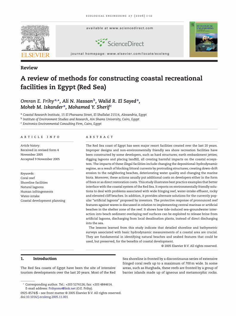
Fig. 1 – Map of the Egyptian Red Sea and Gulf of Suez stGeomorphologically, the shoreline of the Red Sea varies inshape and composition from rocky to sandy, with low or highrelief topography. This shoreline is backed by a wide coastalplain followed by rocky mountains belonging to the EasternDesert or to Sinai Peninsula (Fig. 1). The tide of the Red Seais semi-diurnal with gradually decreasing magnitude from2 m near the city of Suez to the nodal zero point at the cityof El-Tor, some 210 km to the south (Nir, 1996). Winds mainlyblow from the NW and N during most of the year with a smallcomponent from the NE quadrant. Occasionally, winds blow
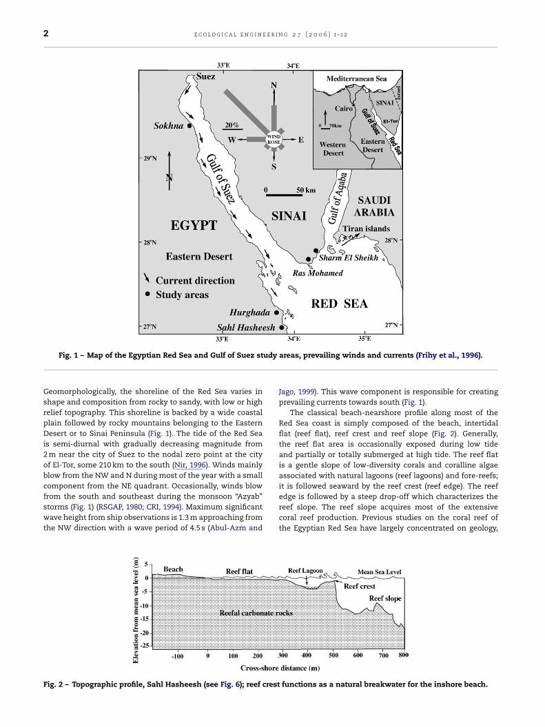
from the south and southeast during the monsoon “Azyab”storms (Fig. 1) (RSGAP, 1980; CRI, 1994). Maximum significantwave height from ship observations is 1.3 m approaching fromthe NW direction with a wave period of 4.5 s (Abul-Azm andFig. 2 – Topographic profile, Sahl Hasheesh (see Fig. 6); reef crest
areas, prevailing winds and currents (Frihy et al., 1996).
Jago, 1999). This wave component is responsible for creatingprevailing currents towards south (Fig. 1).
The classical beach-nearshore profile along most of theRed Sea coast is simply composed of the beach, intertidalflat (reef flat), reef crest and reef slope (Fig. 2). Generally,the reef flat area is occasionally exposed during low tideand partially or totally submerged at high tide. The reef flatis a gentle slope of low-diversity corals and coralline algaeassociated with natural lagoons (reef lagoons) and fore-reefs;it is followed seaward by the reef crest (reef edge). The reef
edge is followed by a steep drop-off which characterizes thereef slope. The reef slope acquires most of the extensivecoral reef production. Previous studies on the coral reef ofthe Egyptian Red Sea have largely concentrated on geology,functions as a natural breakwater for the inshore beach.
e r i n
grtSE((
chthfio((
F(a
e c o l o g i c a l e n g i n e
eochemistry, mineralogical and biological attributes withelatively little emphasis on engineering works related toourism facilities. Among these studies are Crossland (1939),hukri and Higazy (1944), Said (1951), Braithwaite (1982),l Sayed (1984), Moussa et al. (1991), Abul-Azm and Rakha1997), Abul-Azm and Jago (1999), and Hiipner and Windelberg1996).
Because of the unawareness of the importance and deli-acy of Red Sea ecosystems many of the recreation facilitiesave been implemented based on improper designs that failedo consider environmental dimensions. Such developmentsave created diverse impacts on the coastal environments
ronting some of the recreation projects. These impacts,
ncluding the recreation facilities “infringements” along partsf the Red Sea, have been discussed by, among others, CRI1994), Frihy et al. (1996), El-Gamily et al. (2001), Moufaddal2005) and Dewidar (2002). Based on remote sensing analysis
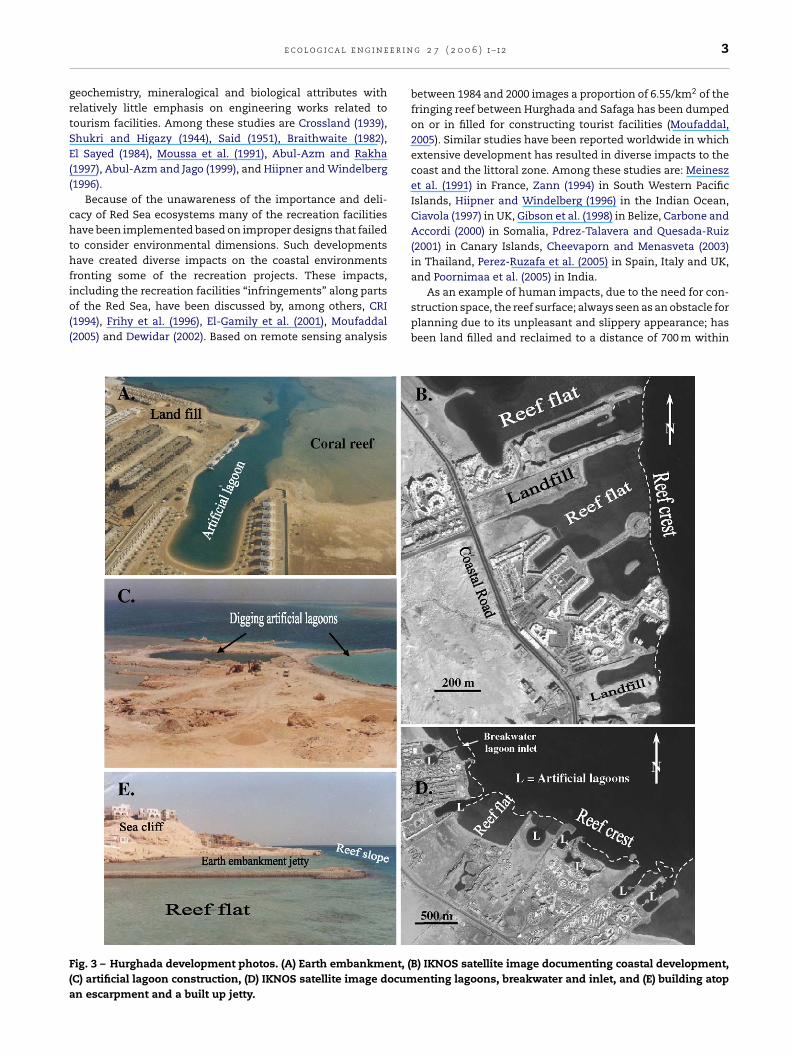
ig. 3 – Hurghada development photos. (A) Earth embankment, (BC) artificial lagoon construction, (D) IKNOS satellite image documn escarpment and a built up jetty.
g 2 7 ( 2 0 0 6 ) 1–12 3
between 1984 and 2000 images a proportion of 6.55/km2 of thefringing reef between Hurghada and Safaga has been dumpedon or in filled for constructing tourist facilities (Moufaddal,2005). Similar studies have been reported worldwide in whichextensive development has resulted in diverse impacts to thecoast and the littoral zone. Among these studies are: Meineszet al. (1991) in France, Zann (1994) in South Western PacificIslands, Hiipner and Windelberg (1996) in the Indian Ocean,Ciavola (1997) in UK, Gibson et al. (1998) in Belize, Carbone andAccordi (2000) in Somalia, Pdrez-Talavera and Quesada-Ruiz(2001) in Canary Islands, Cheevaporn and Menasveta (2003)in Thailand, Perez-Ruzafa et al. (2005) in Spain, Italy and UK,and Poornimaa et al. (2005) in India.
As an example of human impacts, due to the need for con-struction space, the reef surface; always seen as an obstacle forplanning due to its unpleasant and slippery appearance; hasbeen land filled and reclaimed to a distance of 700 m within
) IKNOS satellite image documenting coastal development,enting lagoons, breakwater and inlet, and (E) building atop
e e r i n
4 e c o l o g i c a l e n g i nthe sea (Fig. 3B). Other illegal perpetuations include excava-tions for creating artificial swimming pools (Fig. 3A and C),dumping large amount of fillings on the reef flat to create extraspaces (Fig. 3B) as well as building solid embankments to beused as jetties and mooring areas (Fig. 3E). Subsequently, thereef ecosystem has suffered dramatic and irreversible damage.The depositional-hydrodynamic pattern has been affected asa result of blocking littoral currents by protruded construc-tions (Fig. 3B and D), subsequently, some coastal segmentshave been subjected to local down drift erosion. These con-sequences are also associated with changing water qualityand a deterioration in the marine ecosystem. Economic conse-quences in the form of penalties and environmental restora-tion are expected.
Six case studies have been selected for evaluation along theRed Sea coast of Egypt. No detail monitoring plans has doneto investigate the impacts of the evaluated case studies onthe surrounding environment. Our evolution of environmentalsuccess criteria for the evaluated cases is based on the guide-lines published by the EEAA (1996) and TDA (1998), and alsofrom our experience gained from various coastal engineeringworks executed locally in Egypt and published worldwide. Alsobased on field observations and officially accepted Environ-mental Impact Assessment (EIA) studies of coastal projectsdone by the authors. Although some examples of poor envi-ronmental development exist, many examples of sound envi-ronmental planning and designs for recreational developmentcan be cited.
We report here on some real world examples showing howdetailed coastal and marine surveys can help in identifyingsites potentials and constraints (sensitivity analysis) and howthese are used to optimize recreational coastal developmentwhile safeguarding the environment. The case studies pre-sented in this study are selected from recreation resorts atSokhna, Sharm El Sheikh and Hurghada (Fig. 1).
2. Natural reef lagoons
Thorough site surveys have shown that in some areas alongthe Gulfs of Suez and Aqaba and the Red Sea the reef flatis discontinuous, incorporating remarkable natural lagoonsof various sizes which could be used as swimming poolsor for snorkeling (Fig. 2). Exploiting these lagoons would beeconomically cheaper, environmentally sound, and moresustainable than creating conventional artificial lagoons.This would avoid dredging, which is illegal (EEAA, 1996; TDA,1998), and destruction of marine life. The bottom of thesereef lagoons may be sandy, partially covered by seagrassor with patches of living corals. The ultimate use of suchnatural lagoons would be decided based on the nature ofthe bottom and the bottom biota. For example, those withseagrass beds could be kept untouched since these are con-sidered good nurseries for fish. Those with living corals couldbe used for snorklers, given the carrying capacity of each
lagoon. When having sandy bottoms, lagoons are well suitedfor swimming. However, the water depth during both highand low tides must be taken into consideration as a majorsafety factor that determines the potential users of eachlagoon.g 2 7 ( 2 0 0 6 ) 1–12
3. Access walkways
Provision of safe access to such lagoons is another challengefor developers. Reef flats are usually slippery due to algalgrowth or hard to walk on due to protruded fossilized corals,and, therefore, they may pose safety hazard for visitors. Walk-ways or access ways are preferable to provide secure and envi-ronmentally appropriate means of access (EEAA, 1996; TDA,1998). The primary advantage of these walkways is that theyassure sufficient water exchange in the area with only minorchanges in the sedimentation pattern of the coastline. Thiswould avoid beach erosion at the down drift side of adja-cent beaches. Walkways are usually constructed more or lessperpendicular to the coastline. They may be fixed or float-ing or a combination of both. The fixed type may be solid(submerged or emerged) or pile-supported structures. Typesand criteria to select the relevant walkways and their routesdepend on several factors. These factors include water depth(bathymetry), seabed gradient, tidal range, walkway length,seabed bio-system and hydrodynamic state of the project site.
3.1. Underwater walkways
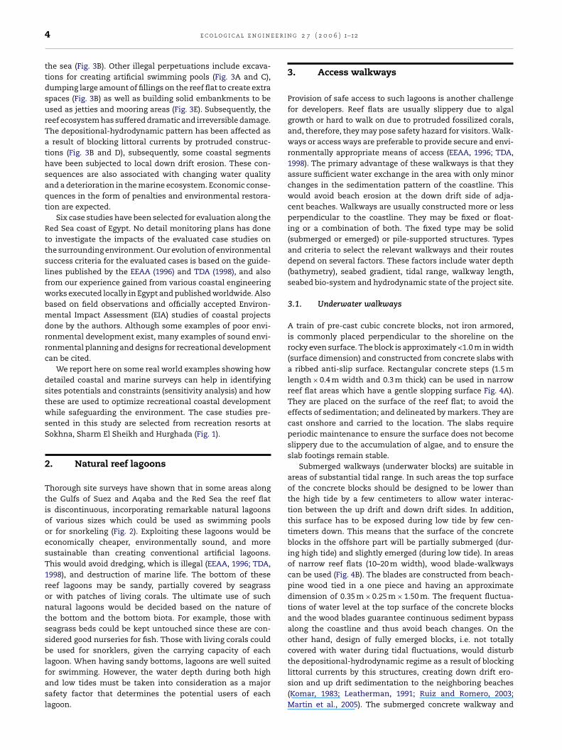
A train of pre-cast cubic concrete blocks, not iron armored,is commonly placed perpendicular to the shoreline on therocky even surface. The block is approximately <1.0 m in width(surface dimension) and constructed from concrete slabs witha ribbed anti-slip surface. Rectangular concrete steps (1.5 mlength × 0.4 m width and 0.3 m thick) can be used in narrowreef flat areas which have a gentle slopping surface Fig. 4A).They are placed on the surface of the reef flat; to avoid theeffects of sedimentation; and delineated by markers. They arecast onshore and carried to the location. The slabs requireperiodic maintenance to ensure the surface does not becomeslippery due to the accumulation of algae, and to ensure theslab footings remain stable.
Submerged walkways (underwater blocks) are suitable inareas of substantial tidal range. In such areas the top surfaceof the concrete blocks should be designed to be lower thanthe high tide by a few centimeters to allow water interac-tion between the up drift and down drift sides. In addition,this surface has to be exposed during low tide by few cen-timeters down. This means that the surface of the concreteblocks in the offshore part will be partially submerged (dur-ing high tide) and slightly emerged (during low tide). In areasof narrow reef flats (10–20 m width), wood blade-walkwayscan be used (Fig. 4B). The blades are constructed from beach-pine wood tied in a one piece and having an approximatedimension of 0.35 m × 0.25 m × 1.50 m. The frequent fluctua-tions of water level at the top surface of the concrete blocksand the wood blades guarantee continuous sediment bypassalong the coastline and thus avoid beach changes. On theother hand, design of fully emerged blocks, i.e. not totallycovered with water during tidal fluctuations, would disturbthe depositional-hydrodynamic regime as a result of blocking
littoral currents by this structures, creating down drift ero-sion and up drift sedimentation to the neighboring beaches(Komar, 1983; Leatherman, 1991; Ruiz and Romero, 2003;Martin et al., 2005). The submerged concrete walkway and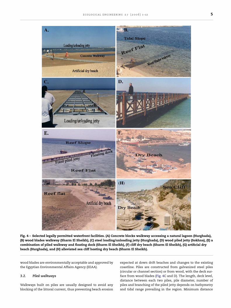
e c o l o g i c a l e n g i n e e r i n g 2 7 ( 2 0 0 6 ) 1–12 5
Fig. 4 – Selected legally permitted waterfront facilities. (A) Concrete blocks walkway accessing a natural lagoon (Hurghada),(B) wood blades walkway (Sharm El Sheikh), (C) steel loading/unloading jetty (Hurghada), (D) wood piled jetty (Sokhna), (E) ac heikb ch (S
wt
3
Wb
ombination of piled walkway and floating dock (Sharm El Seach (Hurghada), and (H) alleviated sea cliff hosting dry bea
ood blades are environmentally acceptable and approved byhe Egyptian Environmental Affairs Agency (EEAA).
.2. Piled walkways
alkways built on piles are usually designed to avoid anylocking of the littoral current, thus preventing beach erosion
h), (F) cliff dry beach (Sharm El Sheikh), (G) artificial dryharm El Sheikh).
expected at down drift beaches and changes to the existingcoastline. Piles are constructed from galvanized steel piles(circular or channel section) or from wood, with the deck sur-
face from wood blades (Fig. 4C and D). The length, deck level,distance between each two piles, pile diameter, number ofpiles and branching of the piled jetty depends on bathymetryand tidal range prevailing in the region. Minimum distance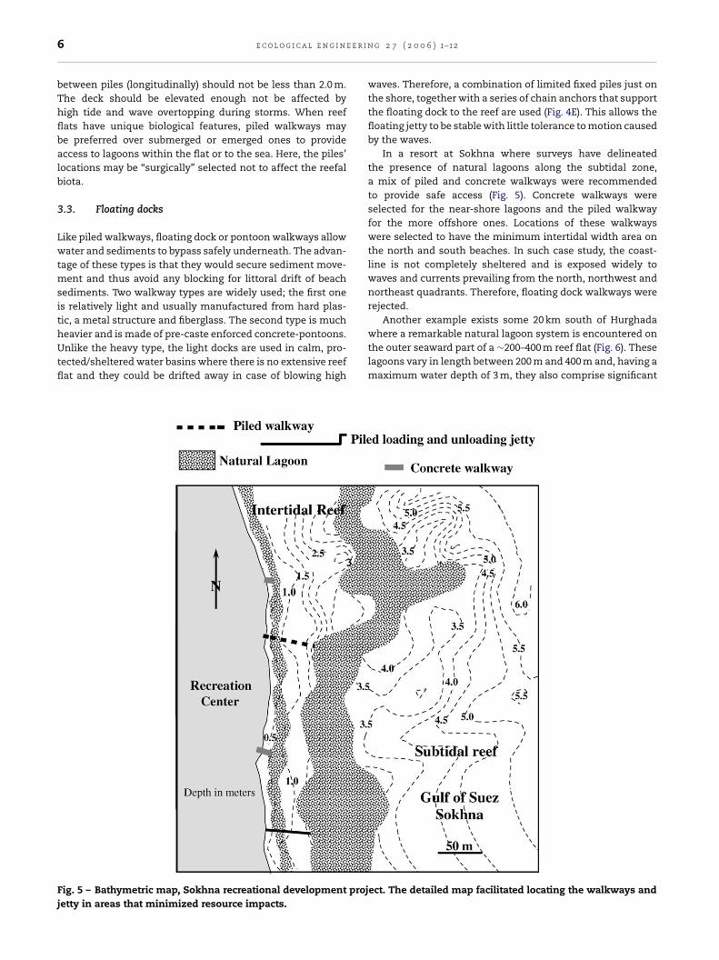
e e r i n
6 e c o l o g i c a l e n g i nbetween piles (longitudinally) should not be less than 2.0 m.The deck should be elevated enough not be affected byhigh tide and wave overtopping during storms. When reefflats have unique biological features, piled walkways maybe preferred over submerged or emerged ones to provideaccess to lagoons within the flat or to the sea. Here, the piles’locations may be “surgically” selected not to affect the reefalbiota.
3.3. Floating docks
Like piled walkways, floating dock or pontoon walkways allowwater and sediments to bypass safely underneath. The advan-tage of these types is that they would secure sediment move-ment and thus avoid any blocking for littoral drift of beachsediments. Two walkway types are widely used; the first oneis relatively light and usually manufactured from hard plas-tic, a metal structure and fiberglass. The second type is much
heavier and is made of pre-caste enforced concrete-pontoons.Unlike the heavy type, the light docks are used in calm, pro-tected/sheltered water basins where there is no extensive reefflat and they could be drifted away in case of blowing highFig. 5 – Bathymetric map, Sokhna recreational development projjetty in areas that minimized resource impacts.
g 2 7 ( 2 0 0 6 ) 1–12
waves. Therefore, a combination of limited fixed piles just onthe shore, together with a series of chain anchors that supportthe floating dock to the reef are used (Fig. 4E). This allows thefloating jetty to be stable with little tolerance to motion causedby the waves.
In a resort at Sokhna where surveys have delineatedthe presence of natural lagoons along the subtidal zone,a mix of piled and concrete walkways were recommendedto provide safe access (Fig. 5). Concrete walkways wereselected for the near-shore lagoons and the piled walkwayfor the more offshore ones. Locations of these walkwayswere selected to have the minimum intertidal width area onthe north and south beaches. In such case study, the coast-line is not completely sheltered and is exposed widely towaves and currents prevailing from the north, northwest andnortheast quadrants. Therefore, floating dock walkways wererejected.
Another example exists some 20 km south of Hurghada
where a remarkable natural lagoon system is encountered onthe outer seaward part of a ∼200–400 m reef flat (Fig. 6). Theselagoons vary in length between 200 m and 400 m and, having amaximum water depth of 3 m, they also comprise significantect. The detailed map facilitated locating the walkways and
e c o l o g i c a l e n g i n e e r i n
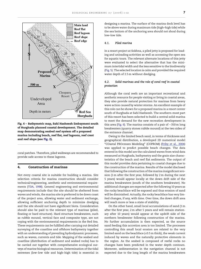
Fig. 6 – Bathymetric map, Sahl Hasheesh Embayment southof Hurghada planned coastal development. The detailedmap demonstrating seabed reef system off a proposedmarina including beach, reef flat, reef lagoons, reef cresta
cp
4
NstmrwoaasflacTswscbve
nd reef slope (see Fig. 2).
oral patches. Therefore, piled walkways are recommended torovide safe access to these lagoons.
. Construction of marinas
ot every coastal site is suitable for building a marina. Siteelection criteria for marina construction should considerechnical/engineering, aesthetic and environmental require-
ents (TDA, 1998). General engineering and environmentalequirements include that the site should be sheltered fromaves and winds, the marina site is preferred to be down coastf the project area, allowing water and sediment exchange,llowing sufficient anchoring depth to minimize dredgingnd the site should not have significant biota. Considerationhould also be paid to the relevant type of marinas (piled,oating or hard structure). Hard structure breakwaters, suchs rubble mound, vertical face and composite type, are notoping with the environmental requirements in the Red Sea.hese requirements can be fulfilled after carrying out detailedurveying of the coastline and offshore bathymetry togetherith an understanding of prevailing hydrodynamic processes,
uch as waves, currents and tide. Mapping of the seabed and
oastline (distribution of sediment and seabed rocks) has toe carried out together with comprehensive ecological sur-eys of marine biological resources. Determination of the tidalxtremes (low–low tide and high–high tide) is essential ing 2 7 ( 2 0 0 6 ) 1–12 7
designing a marina. The surface of the marina dock level hasto be above water during maximum tide (high–high tide) whilethe sea bottom of the anchoring area should not shoal duringlow–low tide.
4.1. Piled marina
In a resort project at Sokhna, a piled jetty is proposed for load-ing and unloading activities as well as accessing the open seafor aquatic tours. The relevant alternate locations of this jettywere evaluated to select the alternative that has the mini-mum intertidal width and the less sensitive to the biodiversity(Fig. 5). The selected location is calm and provided the requiredwater depth of 2.5 m without dredging.
4.2. Solid marinas and the role of coral reef in coastalprotection
Although the coral reefs are an important recreational andaesthetic resource for people visiting or living in coastal areas,they also provide natural protection for marinas from heavywave action caused by winter storms. An excellent example ofthis role can be shown for a proposed marina in a resort centersouth of Hurghada at Sahl Hasheesh. The southern-most partof this resort has been selected to build a central solid marinato meet the demand for the new recreation development inthis area (Fig. 6). The marina consists of a pair of ∼350 m longbreakwaters (quarry stones rubble mound) at the two sides ofthe entrance channel.
Owing to the limited beach sand, in terms of thickness andgeographical distribution, a developed 2D numerical model“COastal PROcesses Modeling” (COPROM) (Frihy et al., 2004)was applied to predict possible beach changes. The dataentered in this model are the calculated waves from wind datameasured at Hurghada, bathymetry and the grain size charac-teristics of the beach and reef flat sediments. The output ofthis model provides data pertaining to coastal changes due tothe construction of the marina. Results of the model disclosedthat following the construction of the marina insignificant ero-sion (1 m after the first year, followed by 2 m during the next5 years) would appear locally at the down drift side of themarina breakwaters (south of the southern breakwater). Noadditional changes are expected after the following 10 years asthe rocky beachface will be exposed and thus erosion of sandwill be diminished. Actually, the rocky beachface has very lim-ited changes, if any, with time. Over time, the down drift areawill reach more or less a state of stability.
On the other hand, small local accumulations of sand (1 mafter the first year, 2 m after 5 years and will remain station-ary after 10 years) would appear at the updrift side of thenorthern breakwater following construction of the marina.No further accumulation is then expected, as the sourcesand feeding this accretion area is too limited. The processescontrolling this small local erosion are related to the verylimited sand on the beachface (<0.5 m thick), the weak currentinduced by waves and the naturally protective elements in
the region. As the seabed is composed of reefal rocks nochanges have been predicted in the water depth contours.Moreover, sedimentation in the navigation channel is notexpected due to the long length of the marina breakwaters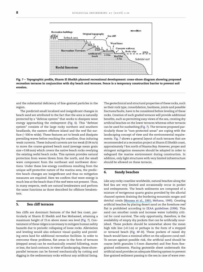
8 e c o l o g i c a l e n g i n e e r i n g 2 7 ( 2 0 0 6 ) 1–12
Fig. 7 – Topographic profile, Sharm El Sheikh planned recreational development: cross-shore diagram showing proposedrecreation terraces in conjunction with dry beach and terraces. Fence is a temporary construction barrier to prevent soil
erosion.and the substantial deficiency of fine-grained particles in theregion.
The predicted small localized and insignificant changes inbeach sand are attributed to the fact that the area is naturallyprotected by a “defense system” that works to dissipate waveenergy approaching the embayment (Fig. 6). This “defensesystem” consists of the large rocky northern and southernheadlands, the eastern offshore island and the reef flat sur-face (∼500 m wide). These features act to break and dissipateprevailing waves before reaching the coastline, thus inducingweak currents. These induced currents are too weak (0.04 m/s)to move the coarse-grained beach sand (average mean grainsize = 0.68 mm) which covers the native beach rocks overlyingthe existing reefal beach rocks. This system provides naturalprotection from waves blown from the north, and the smallwave component from the northeast and northwest direc-tions. Under these low-energy conditions resulting from theunique self-protective nature of the marina area, the predic-tive beach changes are insignificant and thus no mitigationmeasures are required. Here we confirm that wave energy ismuch less at the beach than if the reef were not present. Thus,in many respects, reefs are natural breakwaters and performthe same functions as those described for offshore breakwa-ters.
5. Sea cliff terraces
Sea cliffs are dominant features of the Red Sea coast, par-ticularly at Sharm El Sheikh and Ras Mohamed, attaining amaximum height of 15 m above mean sea level (Fig. 7). Con-tainment of these ridges is necessary to mitigate human safetyhazards due to periodic collapsing of loose rocks. Alleviationand leveling would also enhance visual quality and provid-ing extra land for additional recreation facilities. In order toovercome these problems, flat areas in the form of terraces
(stepped areas) can be mechanically created following, moreor less, the land contours. In view of landscaping, these shore-parallel terraces can be formed mechanically by cutting anddigging in the sedimentary rocks without any artificial lining.The geotechnical and structural properties of these rocks, suchas their rock type, consolidation, hardness, joints and possiblefractures/faults, have to be considered before leveling of theserocks. Creation of such graded terraces will provide additionalbenefits, such as permitting easy views of the sea, creating dryartificial beaches on the lower terraces whereas other terracescan be used for sunbathing (Fig. 7). The terraces proposed par-ticularly those in “non-protected areas” are coping with thelandscaping concept of view and the environmental require-ments. Fig. 7 shows a general layout of such terraces that arerecommended at a recreation project at Sharm El Sheikh coast,approximately 7 km north of Naama Bay. However, proper andstringent mitigation measures should be adopted in order tosafeguard the marine environment during construction. Inaddition, only light structures with very limited infrastructureshould be allowed on these terraces.
6. Sandy beaches
Like any rocky coastline worldwide, natural beaches along theRed Sea are very limited and occasionally occur in pocketand embayments. The beach sediments are composed of amixture of terrigenous quartz grains provided by the alluvialchannel system draining the bordering mountain ranges anddetrital corals (Moussa et al., 1991; Mehana, 1995). Creatingartificial beaches by placing desert sand on the foreshore reefflat is prohibited according to EEAA guidelines (1996). Thissand can smother corals and increase water turbidity criti-cal for coral survival. The only opportunity, therefore, is theavailability of empty dry pockets that can be artificially nour-ished. These pockets should be somewhat above the meanhigh tide line (>0.1 m) or perhaps in the form of a steppedor terraced beach (Fig. 4F–H). These pockets of raised drybeach would have a minimal effect on the adjacent coral reef.To secure against possible risk, the artificial sand should be
coarse (with granules 1–5 mm diameter) and free from fine-grained sediments. Placing geotextile sheet underneath theartificial sand provides an adequate filtering system to preventfine-grained sediment passing to the sea in case of wave over-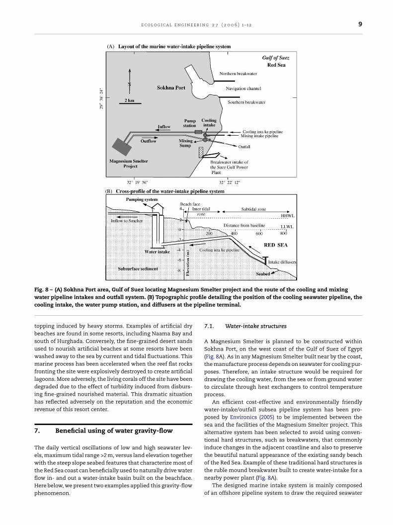
e c o l o g i c a l e n g i n e e r i n g 2 7 ( 2 0 0 6 ) 1–12 9
Fig. 8 – (A) Sokhna Port area, Gulf of Suez locating Magnesium Smelter project and the route of the cooling and mixingw rofilec pipe
tbsuwmfldihr
7
TewtflHp
ater pipeline intakes and outfall system. (B) Topographic pooling intake, the water pump station, and diffusers at the
opping induced by heavy storms. Examples of artificial dryeaches are found in some resorts, including Naama Bay andouth of Hurghada. Conversely, the fine-grained desert sandssed to nourish artificial beaches at some resorts have beenashed away to the sea by current and tidal fluctuations. Thisarine process has been accelerated when the reef flat rocks
ronting the site were explosively destroyed to create artificialagoons. More adversely, the living corals off the site have beenegraded due to the effect of turbidity induced from disburs-
ng fine-grained nourished material. This dramatic situationas reflected adversely on the reputation and the economicevenue of this resort center.
. Beneficial using of water gravity-flow
he daily vertical oscillations of low and high seawater lev-ls, maximum tidal range >2 m, versus land elevation together
ith the steep slope seabed features that characterize most ofhe Red Sea coast can beneficially used to naturally drive waterow in- and out a water-intake basin built on the beachface.ere below, we present two examples applied this gravity-flowhenomenon.
detailing the position of the cooling seawater pipeline, theline terminal.
7.1. Water-intake structures
A Magnesium Smelter is planned to be constructed withinSokhna Port, on the west coast of the Gulf of Suez of Egypt(Fig. 8A). As in any Magnesium Smelter built near by the coast,the manufacture process depends on seawater for cooling pur-poses. Therefore, an intake structure would be required fordrawing the cooling water, from the sea or from ground waterto circulate through heat exchangers to control temperatureprocess.
An efficient cost-effective and environmentally friendlywater-intake/outfall subsea pipeline system has been pro-posed by Environics (2005) to be implemented between thesea and the facilities of the Magnesium Smelter project. Thisalternative system has been selected to avoid using conven-tional hard structures, such as breakwaters, that commonlyinduce changes in the adjacent coastline and also to preservethe beautiful natural appearance of the existing sandy beachof the Red Sea. Example of these traditional hard structures is
the ruble mound breakwater built to create water-intake for anearby power plant (Fig. 8A).The designed marine intake system is mainly composedof an offshore pipeline system to draw the required seawater
10 e c o l o g i c a l e n g i n e e r i n g 2 7 ( 2 0 0 6 ) 1–12
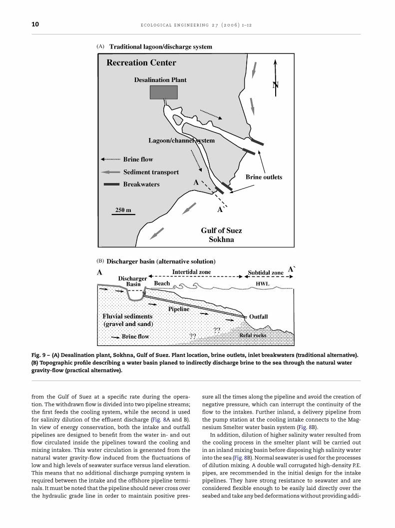
Fig. 9 – (A) Desalination plant, Sokhna, Gulf of Suez. Plant location, brine outlets, inlet breakwaters (traditional alternative).direc
(B) Topographic profile describing a water basin planed to ingravity-flow (practical alternative).
from the Gulf of Suez at a specific rate during the opera-tion. The withdrawn flow is divided into two pipeline streams;the first feeds the cooling system, while the second is usedfor salinity dilution of the effluent discharge (Fig. 8A and B).In view of energy conservation, both the intake and outfallpipelines are designed to benefit from the water in- and outflow circulated inside the pipelines toward the cooling andmixing intakes. This water circulation is generated from thenatural water gravity-flow induced from the fluctuations oflow and high levels of seawater surface versus land elevation.
This means that no additional discharge pumping system isrequired between the intake and the offshore pipeline termi-nals. It must be noted that the pipeline should never cross overthe hydraulic grade line in order to maintain positive pres-tly discharge brine to the sea through the natural water
sure all the times along the pipeline and avoid the creation ofnegative pressure, which can interrupt the continuity of theflow to the intakes. Further inland, a delivery pipeline fromthe pump station at the cooling intake connects to the Mag-nesium Smelter water basin system (Fig. 8B).
In addition, dilution of higher salinity water resulted fromthe cooling process in the smelter plant will be carried outin an inland mixing basin before disposing high salinity waterinto the sea (Fig. 8B). Normal seawater is used for the processesof dilution mixing. A double wall corrugated high-density P.E.
pipes, are recommended in the initial design for the intakepipelines. They have strong resistance to seawater and areconsidered flexible enough to be easily laid directly over theseabed and take any bed deformations without providing addi-
r i n g
tiER
7
AiaitTatsttrwswiigstrtcobtpprtits
covbnsbsweedt
8
Ta
r
e c o l o g i c a l e n g i n e e
ional internal stresses. Such efficient pipeline intake systems incompliance with the Environmental Law No. 4, 1994 andEAA guidelines for implementing coastal structures in theed Sea of Egypt.
.2. Artificial lagoon inlets
rtificial coastal lagoons are commonly constructed by dredg-ng and connecting to the sea with one or more inlets (Fig. 3And D). Direct discharging water through an effluent to the seas not approved by the EEAA due to possible contamination ofhe seawater and subsequent adverse impacts on the ecology.he artificial channel/lagoon system built at a resort villaget Sokhna on the western shore of Suez Gulf was designedo dispose of brine generated from a desalination plant to theea via two inlets (Fig. 9A). Consequently, coastal protection ofhese effluents (inlets) by constructing conventional breakwa-ers would negatively impact the depositional-hydrodynamicegime as a result of blocking littoral currents by these break-aters and creating down drift erosion to the neighboring
outhern beach and accretion on the updrift areas associatedith sedimentation into the two artificial inlets. In contrast,
t was proposed, therefore, to benefit from the hydraulicnteraction between tide fluctuations (140 cm tidal range) andround water level. The hydrodynamic flow induced fromea/ground water interaction through the beach sedimenthat overlay the reef surface would be exploited to naturallyelease the excessive brine to the sea without direct connec-ion between them (Fig. 9B). The relationship between tidalhanges (semi-diurnal and diurnal tides) and the fluctuationf ground water level on sandy beaches have been confirmedy Clarke and Eliot (1977) and Lanyon et al. (1982). To speedhe process of brine discharge by using this measure it is pro-osed to connect the water basin and the sea via a submergedipeline (Fig. 9B). This will act as an emergency measure toelease excessive brine particularly in summer holidays whenhe center will be at full capacity. To avoid any sedimentationn the seaward terminal of this pipeline it is recommendedo place the opening terminal on a rocky seabed in the tidallope.
This alternative is selected not only to avoid any shorelinehanges but also to preserve the beautiful natural appearancef the existing sandy beach. The present landscape/authenticiew will be enhanced by creating the two small lagoons at theeach berm that represent the beach-terminals of the chan-el/lagoon system. The design parameters of such basins,uch as geometric dimensions, location, water depth, shape,ank elevation, and land/sea slope depend on specific mea-urements. Most important is the temporal measuring ofater level fluctuations in the sea (tide variations) and in an
xperimental borehole in the beach to confirm the potentialxchange between the sea and water level in the beach. Aetailed bathymetric survey is necessary to locate the best siteo place the outfall pipeline opening on the seabed.
. Conclusions
he present study provides practical examples to plannersnd investors interested in implementing successful and envi-
2 7 ( 2 0 0 6 ) 1–12 11
ronmentally friendly waterfront tourism. It shows examplesof types and nature of shorelines/coasts, and reef-land inter-faces, the importance of these types and how they may influ-ence the potential recreational uses of coastal development.Failure to understand and grasp this basic concept (i.e. thatthe type and nature of a coast influences potential environ-mentally friendly uses) is the major cause of the environmen-tal damage during development. Based on experience in thisfield, the study pinpoints some recommendations. Developersshould be educated to be able to value nature and its resourcesand processes. They should be able to recognize that eachsite/area has its own potentials and constraints. Here, the roleof the Egyptian Tourism Development Authority (ETDA) is ofparamount importance. Developers and consultants shouldwork together from day 1 to study and understand the natureof the development site and to plan accordingly. Developersshould also avoid “desk-top designs” which fail to considernature. Field surveys are essential to study the coast andmarine components and processes of a particular site. Theinformation gathered through these surveys opens a lot ofopportunities and can inspire innovative environmental solu-tions. For example, the relatively high tidal range versus landelevation together with the seabed features can beneficiallyutilizing to naturally drive water flow in- and out a water-intake basin for coastal facilities. The presented study casesare both cost-effective and environmentally friendly, and thussustainable.
e f e r e n c e s
Abul-Azm, A.G., Jago, P.A., 1999. Touristic development in theEgyptian Red Sea: an EIA approach. In: Fifth InternationalConference on Coastal and Port Engineering in DevelopingCountries, pp. 1958–1969.
Abul-Azm, A.G., Rakha, K.A., 1997. Environmental concerns formarina planning in the Gulf of Suez. In: MEDCOAST’ 97Conference, Malta, pp. 986–995.
Braithwaite, C.J., 1982. Patterns of accretion of reefs in theSudanese Red Sea. Marine Geol. 46, 297–325.
Carbone, F., Accordi, G., 2000. The Indian Ocean coast ofSomalia. Marine Pollut. Bull. 41, 141–159.
Cheevaporn, V., Menasveta, P., 2003. Water pollution andhabitat degradation in the Gulf of Thailand. Marine Pollut.Bull. 47, 43–51.
Ciavola, P., 1997. Coastal dynamics and impact of coastalprotection works on the Spurn Head spit (UK). Catena 30,369–389.
Clarke, D.J., Eliot, I.G., 1977. Groundwater-level changes in acoastal dune, sea-level fluctuations and shorelinemovement on a sandy beach. Marine Geol. 77, 319–326.
CRI (Coastal Research Institute), 1994. Studies andrecommendations for alleviating the negative impacts of theinfringements on the coastal zone between km 15 to km23.70 (Hurghada/Safaga) Road in the Red Sea. TechnicalReports, Alexandria, Egypt, 140 pp.
Crossland, C., 1939. Some coral formations. In: Report on thepreliminary expedition for the exploration of the Red Sea in
the RRS “Mabahith”, vol. 1. Marine Biological StationGhardaqa, pp. 21–35.Dewidar, Kh.M., 2002. Landfill detection in Hurghada, NorthRed Sea, Egypt using Thematic Mapper images. Int. J.Remote Sensing 5, 939–948.

e r i n
12 e c o l o g i c a l e n g i n eEEAA (Egyptian Environmental Affairs Agency), 1996. Guidelinefor development in coastal areas. EnvironmentalManagement Sector, 24 pp.
El-Gamily, H.I., Nasr, S., Raey, M., 2001. An assessment ofnatural and human-induced changes along Hurghada andRas Abu Soma coastal area, Red Sea, Egypt. Int. J. RemoteSensing, 1–16 (preview article).
El Sayed, M.Kh., 1984. Reefal sediments of Al-Ghardaqa,northern Red Sea, Egypt. Marine Geol. 56, 217–259.
Environics (Environmental Consulting Firm), 2005. Thepreliminary design of the marine intake and outfall worksfor the Magnesuim Smelter Project, Sokhna, Gulf of Suez,Red Sea. Cairo, 91 pp.
Frihy, O.E., Fanos, A.M., Khafagy, A.A., Abu Aesha, T., 1996.Human impacts on the coastal zone of Hurghada, NorthernRed Sea, Egypt. Geo-Marine Lett. 16, 324–429.
Frihy, O.E., El Ganaini, M.A., El Sayed, W.R., Iskander, M.M.,2004. The role of fringing coral reef in beach protection ofHurghada, Gulf of Suez Red Sea of Egypt. Ecol. Eng. 22,17–25.
Gibson, J., McField, M., Wells, S., 1998. Coral reef managementin Belize: an approach through integrated coastal zonemanagement. Ocean Coastal Manage. 39, 229–244.
Hiipner, T., Windelberg, J., 1996. Elements of environmentalimpact studies on coastal desalination plants. Desalination108, 11–18.
Komar, P.D., 1983. Handbook of Coastal Processes and Erosion.CRC Press, Boca Raton, FL, 305 pp.
Lanyon, J.A., Eliot, I.G., Clarke, D.J., 1982. Groundwater-levelvariation during semi-diurnal spring tidal cycle on a sandybeach. Aust. J. Marine Freshwater Res. 33, 77–400.
Leatherman, S.P., 1991. Coast and beaches. In: Kiersch, G.A.(Ed.), The Heritage of Engineering Geology, vol. 3. GeologicalSociety of America Centennial Special, pp. 183–200.
Martin, D., Bertasi, F., Colangelo, M., Vries, M., Frost, M.,Hawkinse, S., Macpherson, E., Moschella, P., Satta, M.,Thompson, R., Ceccherelli, V., 2005. Ecological impact ofcoastal defense structures on sediment and mobile fauna:
Evaluating and forecasting consequences of unavoidablemodifications of native habitats. Coastal Eng. 52, 1027–1051.Mehana, A.M., 1995. Flash floods on the eastern desert and RedSea coast. In: Flash Flood Prevention Symposium inHurghada, May 29–June 1.
g 2 7 ( 2 0 0 6 ) 1–12
Meinesz, A., Lefevre, J.R., Astier, J.M., 1991. Impact of coastaldevelopment on the infralittoral zone along theSoutheastern Mediterranean shore of continental France.Marine Pollut. Bull. 23, 343–347.
Moufaddal, W., 2005. Use of satellite imagery as EnvironmentalImpact Assessment tool; a case study from the NW EgyptianRed Sea coastal zone. Environ. Monit. Assess. 107, 427–452.
Moussa, A.A., El Askary, M.A., Nasr, S.M., El Mamoney, M.H.,1991. Unconsolidated reefal sediments in the Jubal Straitregion, Red Sea, Egypt. Marine Geol. 97, 379–390.
Nir, Y., 1996. Sediment transport patterns of southern Sinaicoast and their role in the Holocene development of coralreefs and lagoons. J. Coastal Res. 12, 70–78.
Perez-Ruzafa, A., Garca-Charton, J.A., Barcala, E., Marcos, C.,2005. Changes in benthic fish assemblages as a consequenceof coastal works in a coastal lagoon: The Mar Menor (Spain,Western Mediterranean). Marine Pollut. Bull., in press.
Pdrez-Talavera, J.L., Quesada-Ruiz, D.D., 2001. Identification ofthe mixing processes in brine discharges carried out inBarranco del Toro Beach, south of Gran Canaria (CanaryIslands). Desalination 139, 277–286.
Poornimaa, E.H., Rajaduraia, M., Raob, T.S., Anupkumarb, B.,Rajamohanb, R., Narasimhanb, S.V., Raoa, V.N.,Venugopalanb, V.P., 2005. Impact of thermal discharge froma tropical coastal power plant on phytoplankton. J. Therm.Biol. 30, 307–316.
RSGAP (Red Sea and Gulf of Aden Pilot Book), 1980.Hydrographers of the Navy, 12th ed. HydrographicDepartment, Ministry of Defense, London, 248 pp.
Ruiz, J.M., Romero, J., 2003. Effects of disturbances caused bycoastal constructions on spatial structure, growth dynamicsand photosynthesis of the seagrass Posidonia oceanica.Marine Pollut. Bull. 46, 1523–1533.
Said, R., 1951. Organic origin of some calcareous sedimentfrom the Red Sea. Science 113, 518–519.
Shukri, N.M., Higazy, R.A., 1944. Mechanical analysis of somebottom deposits of the Northern Red Sea. J. Sediment.Petrol. 14, 45–69.
TDA (Tourism Development Authority), 1998. Best practices forTourism Center Development along the Red Sea coast,Egypt, 107 pp.
Zann, L.P., 1994. The status of coral reefs in South WesternPacific Islands. Marine Pollut. Bull. 29, 52–61.