
A review of different strategies for HVAC energy saving
17
A review of different strategies for HVAC energy saving Vahid Vakiloroaya a,⇑ , Bijan Samali b , Ahmad Fakhar c , Kambiz Pishghadam d a Center for Built Infrastructure Research, School of Electrical, Mechanical and Mechatronic Systems, University of Technology, Sydney, Australia b Center for Built Infrastructure Research, School of Civil and Environmental Engineering, University of Technology, Sydney, Australia c Department of Mechanical Engineering, Faculty of Engineering, Azad University of Kashan, Iran d Department of Sustainable and NZEB Solutions, Giacomini Inc., Vancouver, BC, Canada article info Article history: Received 22 April 2013 Accepted 7 October 2013 Keywords: Energy saving Energy-efficient strategies HVAC Buildings abstract Decreasing the energy consumption of heating, ventilation and air conditioning (HVAC) systems is becoming increasingly important due to rising cost of fossil fuels and environmental concerns. Therefore, finding novel ways to reduce energy consumption in buildings without compromising comfort and indoor air quality is an ongoing research challenge. One proven way of achieving energy efficiency in HVAC systems is to design systems that use novel configurations of existing system components. Each HVAC discipline has specific design requirements and each presents opportunities for energy savings. Energy efficient HVAC systems can be created by re-configuring traditional systems to make more stra- tegic use of existing system parts. Recent research has demonstrated that a combination of existing air conditioning technologies can offer effective solutions for energy conservation and thermal comfort. This paper investigates and reviews the different technologies and approaches, and demonstrates their ability to improve the performance of HVAC systems in order to reduce energy consumption. For each strategy, a brief description is first presented and then by reviewing the previous studies, the influence of that method on the HVAC energy saving is investigated. Finally, a comparison study between these approaches is carried out. Ó 2013 Elsevier Ltd. All rights reserved. 1. Introduction Increased standards of living coupled with dwindling supplies of fossil fuels, have forced researchers and engineers to focus on the issue of energy use in buildings. Heating, ventilation and air conditioning (HVAC) systems, which play an important role in ensuring occupant comfort, are among the largest energy consum- ers in buildings. Performance enhancements to traditional HVAC systems therefore offer an exciting opportunity for significant reductions in energy consumption. Almost 50% of the energy de- mand is used to support indoor thermal comfort conditions in commercial buildings [1]. Furthermore, as most people spend more than 90% of their time inside [2], the development of energy-effi- cient HVAC systems that do not rely on fossil fuels will play a key role in reducing energy consumption. A closer look at world- wide energy consumption by HVAC equipment shows noticeable values: HVAC systems constitute over 50% of the building energy consumed in US [3]. In China, the building energy consumption has been increasing about 10% a year for the past 20 years and has comprised about 20.7% of the total national energy usage by the year 2004 [4]. In Europe, around 40% of energy consumption is represented in commercial and residential buildings [5]. In Aus- tralia 70% of power consumption in non-residential buildings is used for HVAC systems [6]. In India, air conditioning systems ac- counts around 32% of electricity consumption of a building [7]. In the subtropical Hong Kong air conditioning and refrigeration sys- tems accounted for 33% in 2006 [8]. More than 70% of building en- ergy consumption is to support cooling systems in Middle East [9]. It was estimated that world energy consumption was increased by 58% between 2001 and 2005 [10]. However, approximately 80% of the energy usage still comes from fossil fuels [11,12]. The growing reliance on HVAC systems in residential, commercial and industrial environments has resulted in a huge increase in energy usage, par- ticularly in the summer months. Developing energy efficient HVAC systems is essential, both to protect consumers from surging power costs and to protect the environment from the adverse im- pacts of greenhouse gas emissions caused by the use of energy- inefficient electrical appliances. With rapid changes in science and technology today, there are several methods that can be used to achieve energy-efficient HVAC systems. In order to develop effi- cient systems, however, a clear understanding of building comfort conditions is necessary. Thermal comfort is all about human satis- faction with their thermal environment. The design and calculation of air conditioning systems to control the thermal environment in a way that also achieves an acceptable standard of air quality inside a building should comply with the ASHRAE standard 55-2004 [13]. 0196-8904/$ - see front matter Ó 2013 Elsevier Ltd. All rights reserved. http://dx.doi.org/10.1016/j.enconman.2013.10.023 ⇑ Corresponding author. Address: P.O. Box 123, Broadway, Sydney, NSW 2007, Australia. Tel.: +61 2 9514 9043; fax: +61 2 9514 2868. E-mail address: [email protected] (V. Vakiloroaya). Energy Conversion and Management 77 (2014) 738–754 Contents lists available at ScienceDirect Energy Conversion and Management journal homepage: www.elsevier.com/locate/enconman
-
Upload
westernsydney -
Category
Documents
-
view
3 -
download
0
Transcript of A review of different strategies for HVAC energy saving

Energy Conversion and Management 77 (2014) 738–754
Contents lists available at ScienceDirect
Energy Conversion and Management
journal homepage: www.elsevier .com/locate /enconman
A review of different strategies for HVAC energy saving
0196-8904/$ - see front matter � 2013 Elsevier Ltd. All rights reserved.http://dx.doi.org/10.1016/j.enconman.2013.10.023
⇑ Corresponding author. Address: P.O. Box 123, Broadway, Sydney, NSW 2007,Australia. Tel.: +61 2 9514 9043; fax: +61 2 9514 2868.
E-mail address: [email protected] (V. Vakiloroaya).
Vahid Vakiloroaya a,⇑, Bijan Samali b, Ahmad Fakhar c, Kambiz Pishghadam d
a Center for Built Infrastructure Research, School of Electrical, Mechanical and Mechatronic Systems, University of Technology, Sydney, Australiab Center for Built Infrastructure Research, School of Civil and Environmental Engineering, University of Technology, Sydney, Australiac Department of Mechanical Engineering, Faculty of Engineering, Azad University of Kashan, Irand Department of Sustainable and NZEB Solutions, Giacomini Inc., Vancouver, BC, Canada
a r t i c l e i n f o
Article history:Received 22 April 2013Accepted 7 October 2013
Keywords:Energy savingEnergy-efficient strategiesHVACBuildings
a b s t r a c t
Decreasing the energy consumption of heating, ventilation and air conditioning (HVAC) systems isbecoming increasingly important due to rising cost of fossil fuels and environmental concerns. Therefore,finding novel ways to reduce energy consumption in buildings without compromising comfort andindoor air quality is an ongoing research challenge. One proven way of achieving energy efficiency inHVAC systems is to design systems that use novel configurations of existing system components. EachHVAC discipline has specific design requirements and each presents opportunities for energy savings.Energy efficient HVAC systems can be created by re-configuring traditional systems to make more stra-tegic use of existing system parts. Recent research has demonstrated that a combination of existing airconditioning technologies can offer effective solutions for energy conservation and thermal comfort. Thispaper investigates and reviews the different technologies and approaches, and demonstrates their abilityto improve the performance of HVAC systems in order to reduce energy consumption. For each strategy, abrief description is first presented and then by reviewing the previous studies, the influence of thatmethod on the HVAC energy saving is investigated. Finally, a comparison study between theseapproaches is carried out.
� 2013 Elsevier Ltd. All rights reserved.
1. Introduction
Increased standards of living coupled with dwindling suppliesof fossil fuels, have forced researchers and engineers to focus onthe issue of energy use in buildings. Heating, ventilation and airconditioning (HVAC) systems, which play an important role inensuring occupant comfort, are among the largest energy consum-ers in buildings. Performance enhancements to traditional HVACsystems therefore offer an exciting opportunity for significantreductions in energy consumption. Almost 50% of the energy de-mand is used to support indoor thermal comfort conditions incommercial buildings [1]. Furthermore, as most people spend morethan 90% of their time inside [2], the development of energy-effi-cient HVAC systems that do not rely on fossil fuels will play akey role in reducing energy consumption. A closer look at world-wide energy consumption by HVAC equipment shows noticeablevalues: HVAC systems constitute over 50% of the building energyconsumed in US [3]. In China, the building energy consumptionhas been increasing about 10% a year for the past 20 years andhas comprised about 20.7% of the total national energy usage bythe year 2004 [4]. In Europe, around 40% of energy consumption
is represented in commercial and residential buildings [5]. In Aus-tralia 70% of power consumption in non-residential buildings isused for HVAC systems [6]. In India, air conditioning systems ac-counts around 32% of electricity consumption of a building [7]. Inthe subtropical Hong Kong air conditioning and refrigeration sys-tems accounted for 33% in 2006 [8]. More than 70% of building en-ergy consumption is to support cooling systems in Middle East [9].It was estimated that world energy consumption was increased by58% between 2001 and 2005 [10]. However, approximately 80% ofthe energy usage still comes from fossil fuels [11,12]. The growingreliance on HVAC systems in residential, commercial and industrialenvironments has resulted in a huge increase in energy usage, par-ticularly in the summer months. Developing energy efficient HVACsystems is essential, both to protect consumers from surgingpower costs and to protect the environment from the adverse im-pacts of greenhouse gas emissions caused by the use of energy-inefficient electrical appliances. With rapid changes in scienceand technology today, there are several methods that can be usedto achieve energy-efficient HVAC systems. In order to develop effi-cient systems, however, a clear understanding of building comfortconditions is necessary. Thermal comfort is all about human satis-faction with their thermal environment. The design and calculationof air conditioning systems to control the thermal environment in away that also achieves an acceptable standard of air quality insidea building should comply with the ASHRAE standard 55-2004 [13].

V. Vakiloroaya et al. / Energy Conversion and Management 77 (2014) 738–754 739
According to this standard, thermal comfort conditions are accept-able when 80% of the building’s occupants are satisfied. In order topredict appropriate thermal comfort conditions an index called apredicted mean vote (PMV), which indicates mean the thermalsensation vote on a standard scale for a large group of people, isused. PMV is defined by six thermal variables for an indoor envi-ronment, subject to human comfort: air temperature, air humidity,air velocity, mean radiant temperature, clothing insulation and hu-man activity. The PMV index predicts the mean value of the voteson the seven point thermal sensation scales; +3: hot, +2: warm, +1:slightly warm, 0: neutral, �1: slightly cool, �2: cool, �3: cold.According to ISO 7730 standard [14], the values of PMV between�1 and 1 are the range in which 75% people are satisfied, while be-tween �0.5 and 0.5 is the range in which 90% people will besatisfied.
Different techniques need to be implemented on HVAC systemsto improve their energy efficiency and reduce their environmentalimpact. In recent years, different control and optimization strate-gies have been used to improve the energy consumption rates ofthese systems [15]. However, these approaches are either expen-sive or very complicated to implement, and require constant mon-itoring [16]. One option to achieve this objective is to combinedifferent HVAC components to create an energy-efficient configu-ration. Because building cooling load varies with the time of theday, an HVAC system should be designed in tandem with an opti-mum design scheme that will keep the process variables to theirrequired set-point in order to maintain comfort under any load
Fig. 1. HVAC energy saving strate
conditions. While optimizing the mechanical design of the tradi-tional HVAC system results in extra upfront costs, these modifica-tions can actually provide substantial savings in the long term byreducing ongoing maintenance costs associated with control andoptimization strategies.
Previous studies have described various technologies that canreduce HVAC energy consumption. However, a comprehensivestudy that describes and compares a wide range of different strat-egies for HVAC energy savings remains a gap in the existing bodyof research in the HVAC field. This study will investigate and re-view the different technologies and approaches, and demonstratetheir ability to improve the performance of HVAC systems to re-duce energy consumption. Fig. 1 shows strategies used to achievegreater HVAC energy efficiency discussed in this study. Varioustechnologies in which different configurations, component combi-nations and mechanical designs are used to improve the energyperformance of HVAC systems are also discussed in this paper.For each strategy, a brief description is first presented and thenby reviewing the previous studies, the influence of that methodon HVAC energy saving is investigated. Finally, a comparison studybetween these approaches is carried out.
2. Evaporative cooling systems
Evaporative cooling technology has been widely used sincemore than a century [17]. Direct evaporative cooling (DEC) systemshave low set-up and running costs, and have been proven to
gies discussed in this study.

740 V. Vakiloroaya et al. / Energy Conversion and Management 77 (2014) 738–754
significantly improve a building’s cooling and ventilation capacitywith minimal energy use. Using water as the working fluid, onecan avoid the use of ozone-destroying chlorofluorocarbons and hy-dro chlorofluorocarbons. Other benefits from this system includeeasy maintenance, easy installation and operation as well as obvi-ating CO2 and other emissions. Evaporative cooling systems canprovide thermal comfort via the conversion of sensible heat to la-tent heat; however, the lowest temperature DEC systems can reachis the wet-bulb temperature of the outside air. Therefore, the tem-perature of the supply air after cooling would be just on the edge ofcomfort and could rise a few degrees in passing through space, tak-ing the temperature beyond the comfort zone. Therefore, the ideais to investigate both the possibility of increasing the utilizationpotential of the evaporative cooling system by combination of dif-ferent components with this system and the capability of improv-ing the performance of other HVAC systems when integrating withevaporative cooling system.
Khalajzadeh et al. [18] presented the thermal behavior of theindirect evaporative cooler (IEC) when combining with a groundheat exchanger and cooling coil unit (CCU) as shown in Fig. 2. Inthis hybrid plant, the coolant water for the cooling coil unit wasprovided by the vertical ground heat exchanger to cool the enter-ing air of an indirect evaporative cooler. The simulation resultsshowed that the proposed hybrid system can result in effectivenessgreater than unity while comfort conditions are met. Vakiloroayaet al. [19] investigated the possibility to increase the effectivenessof an evaporative cooling system by the integration of the air-to-airsensible heat exchanger and cooling coil with the direct evapora-tive cooling process. In such a system, the air is first cooled sensi-bly, i.e. without any moisture addition, in two stages. In the firststage, an air-to-air sensible heat exchanger is used to reduce thedry-bulb air temperature entering the cooling coil. This can be per-formed through the energy transferring between the building re-turn airstream and ambient fresh air. In the second stage the airis further cooled sensibly by a cooling coil. The cooling coil getsits water supply from a cooling tower. Then the air passes throughthe direct evaporative cooling system to achieve a lower tempera-ture. Consequently, in the proposed hybrid evaporative coolingsystem the lowest temperature obtained can be lower than thewet-bulb temperature of the outside air. The performance of new-ly-configured system was then compared with the monitored dataof an existing central cooling plant of a real-world commercialbuilding in terms of the energy saving potential and thermal com-fort. Results indicated that compared to the conventional chilled-water central cooling plant, the new system offers an energy savingpotential up to 52% while maintaining the thermal comfort condi-tions in the building.
Fig. 2. The schematic diagram of hybrid system consists of the ground coupledcircuit and indirect evaporative cooling system (Ref. [18]).
Khandelwal et al. [20] evaluated the potential of reducing theannual energy consumption of a central cooling plant by combin-ing with regenerative evaporative cooling technology to accom-plish the energy conversation objective. The concept of thismethod has been introduced by Lahoti et al. [21]. As shown inFig. 3, the process air first flows through a heat exchanger and getscooled. The pre-cooled air then flows through a direct evaporativecooler and finally is mixed with return air and passes through thechilled water cooling coil located in an air-handling unit (AHU). Asa result, the chiller system load is decreased which in turn reducethe overall power usage of the chiller. Their results showed thatthe proposed system is able to provide 15.69% annual electricitysaving of the building. Heidarnejad et al. [22] studied a hybrid sys-tem of nocturnal radiative cooling, cooling coil and direct evapora-tive cooling. In this proposed system, water is cooled by means ofcirculation the water through a flat-plate radiator throughout thenight. The cooled water is then used to pre-cool the ambient airentering the direct evaporative cooling via a cooling coil unit dur-ing the next day. Their results showed that the effectiveness of theproposed hybrid system is significantly higher than the stand-alone direct evaporative cooling system. Kumar and Riangvilaikul[23] constructed and tested a dew point evaporative cooling sys-tem for sensible cooling of the ventilation air. The purpose wasto supply the outlet air temperature below the ambient wet-bulbtemperature. For this, the hot ambient air is first drawn into adry channel where loses its sensible heat to a wet channel. Somefraction of this air is again reused as a working air in the wet chan-nel where is cooled in direct contact with water. Finally, the work-ing air is rejected to atmosphere. To prevent moisture penetrationbetween the air streams, a thin-film polymer wall is used to sepa-rate the dry and wet channel. Result demonstrated the ability ofthis system to increase the effectiveness of the traditional evapora-tive cooling system at different inlet air conditions.
Delfani et al. [24] investigated the influence of combining theindirect evaporative cooling system with a packaged unit air-con-ditioner on electrical energy consumption. In this configuration theair is pre-cooled by using the indirect evaporative cooler and thenpasses through the packaged cooling unit as demonstrated inFig. 4. Their results indicated that the indirect evaporative coolercan reduce cooling load up to 75% which cause to 55% reductionin power consumption of the packaged air conditioning system.
3. Evaporative-cooled air conditioning system
Recent research reveals that air conditioning systems based onmechanical vapor compression consume significant amounts ofelectricity. Therefore, increasing the coefficient of performance(COP) of these air conditioning systems with air-cooled condensersis a challenging problem. By pre-cooling the air before it reachesthe condenser coil, the condenser is able to reject more heat. Asa result, cooling capacity increases while energy demand and usagefalls. As condensing temperatures are lowered, head pressure is re-duced. This allows the compressor to run less frequently, resultingin an energy saving. The standard design for these systems requiresa frame to be built and filled by evaporative media pads which areinstalled in front of the air-cooled condenser. A water circulationsystem, consisting of a small pump, a tank and pipes, is added.The water then is injected on the top of the media pad. Hot ambi-ent air passes the wet pad and then the condenser to improve thesystem performance. As the hot, ambient air is drawn through themedia, the water absorbs heat and evaporates, lowering the tem-perature of the ambient air and creating a cooler operating envi-ronment for the air-cooled condenser which allows thecondenser to reject additional heat into the atmosphere. The com-pression ratio is then reduced, resulting in reduced energy usage

Fig. 3. Schematic of regenerative air cooler (Ref. [20]).
Fig. 4. The schematic diagram of the indirect evaporative cooling system used for packaged unit air conditioner (Ref. [24]).
V. Vakiloroaya et al. / Energy Conversion and Management 77 (2014) 738–754 741
when the compressor is run. In a similar design, mist ware issprayed directly into the ambient air before passing through theair-cooled condenser.
Hajidavallo and Eghtedari [25] built an evaporative cooler andcoupled to the existing air-cooled condenser of a split air-condi-tioner in order to measure its effect on the cycle performance un-der various ambient air temperatures up to 49 �C as shown inFig. 5. Their experimental results showed that the power consump-tion of the air-conditioner can be reduced up to 20% and the sys-tem COP can be improved around 50%. Youbi-Idrissi et al. [26]developed a numerical model for a sprayed air-cooled condensercoupled to the refrigeration system to study the effect of sprayedwater flow rate on the energy performance of the system. Theyfound that compared to a dry air-cooled condenser, both thecalorific capacity and system COP increase by 13% and 55%
respectively. Another detailed model and numerical simulation ofthe heat transfer characteristics for the evaporative-cooledcondenser were carried out using finite element technique byJahangeer et al. [27]. The results showed that the combined heattransfer coefficient obtained for the evaporative-cooled condenseis very high for the different water film thicknesses on the con-denser tube. Yu and Chen [28] investigated how the COP of air-cooled chillers can be improved by using mist pre-cooling asshown in Fig. 6. Their results estimated that around 18% decreasein the annual electricity usage could be achieved with mist pre-cooling of air entering the air-cooled condenser of the chiller, serv-ing a hotel in a sub-tropical climate. Similar study was carried outby Vrachopoulos et al. [29]. They used a system of drop cloud viawater spraying to an air-cooled condenser. Their results showedthe energy saving up to 58% by using this method. Hwang et al.

Fig. 5. Schematic view of the evaporative-cooled air conditioner (Ref. [25]).
Fig. 6. Pipe and nozzle layouts of a mist system for the condenser of an air-cooledchiller (Ref. [28]).
742 V. Vakiloroaya et al. / Energy Conversion and Management 77 (2014) 738–754
[30] compared the performance of an evaporative-cooled con-denser with that of a conventional air-cooled condenser for a splitheat pump system. The experimented unit was a conventional heatpump with 9 kW cooling capacity in which the air-cooled con-denser was replaced with an evaporative-cooled condenser whilethe evaporator and compressor were retained. In this design, thecondenser tubes were immersed in a water bath where ambientair was blown across the rotated wheel submerged in the waterbath. As the wheel rotated its wetted surfaces pull the film of waterout of the bath into the air stream. The passing air evaporatedsome of the water film, reducing the temperature of remainedwater on the wheel. The condenser tubes rejected heat to the waterbath and the evaporation of the water film rejected heat of the airstream. Therefore, the evaporative condenser had a benefit of alower condensing temperature than that of an air-cooled con-denser. The experimental results showed that the capacity andCOP of the evaporative-cooled system can be increased by 1.8–8.1% and 11.1–21.6% respectively.
4. Ground-coupled HVAC systems
Ground-coupled technology relies on the fact that, at depth, theEarth has a relatively constant temperature that is colder than the
air temperature in summer and warmer than the air temperaturein winter. In this system, under cooling mode, operation heat isdischarged to a ground loop that provides a lower temperatureheat sink than ambient outdoor air temperature. During winterheating operations, heat is extracted from a source that is at a high-er temperature than ambient outdoor air. This system has beenused on a residential and commercial scale since the 1920s [31].Studies on vertical close-loop ground-coupled heat pumps showa yearly reduction of 30–70% in electrical energy consumptionfor heating and cooling when compared to air-to-air heat pumpsystems in a southern climate [32]. As reported in one study[33], the COP of a ground source heat pump (GSHP) was higherthan that of air source heat pump (ASHP) by 74%, due to lower con-densing temperatures in the GSHP system. Another study [34]compared the GSHP and ASHP for an archives building; resultsshowed that while the initial cost for GSHP is more than ASHP,the operating cost of the GSHP can be reduced by 55.8% with a pay-back time of about 2 years. However, GSHPs capture only a smallpercentage of the heating and cooling market due to the high costof installing the ground heat exchanger, which can increase systemcosts by 20–30% [35] and the initial capital cost by 30–50% whencompared to air source units [36]. Nevertheless, these systemscan reduce operating costs via taking benefit of off-peak electricitytariffs [37,38]. This system was widely used in Europe and USA be-tween 2004 and 2007 [39], and about 60% of total public HVACinstallations in Korea in recent decades [40]. In China, use of thissystem is rapidly growing [41]; between 1985 and 2007, therehas been increased number of patent applications for this systemwith 278 patents issues and 157 patents under examination [42].Furthermore, it is estimated that about 1.1 million ground sourceheat pumps have been installed around the world [39]. Comparedwith standard technologies such as vapor compression systems,ground-coupled heat pumps create less noise, reasonable environ-mental safety [43] and can reduce greenhouse gas emissions by66% or more compared with conventional heating and coolingsystems.
Magraner et al. [44] compared the long term energy perfor-mance experimental measurements of a monitored ground cou-pled heat pump system with the predictions from a designprocedure by using TRNSYS simulation tool. The geothermal sys-tem was consisted of a reversible water to water heat pump with15.9 kW of nominal cooling capacity and 19.3 kW of nominal heat-

V. Vakiloroaya et al. / Energy Conversion and Management 77 (2014) 738–754 743
ing capacity, a vertical borehole heat exchanger and a hydraulicgroup. The vertical heat exchanger was made up of 6 boreholesof 50 m depth in a rectangular configuration, with two boreholesin the short side of the rectangle and three in the large side. Theenergy performance of the monitored ground coupled heat pumpsystem was calculated using the instantaneous measurements oftemperature, flow and power consumption. Their results showedthat the heat pump nominal coefficient of performance is theparameter that mostly affects the energy performance predictions.Pardo et al. [45] evaluated the energy efficiency of several air con-ditioning configurations using a heat pump system. They evaluatethe electrical energy consumption of a conventional air to waterheat pump (AWHP) and a conventional ground coupled heat pump(GCHP). Then they combined both AWHP and GCHP to study its en-ergy performance. Afterwards, they combined a stratified watertank as thermal storage device separately with AWHP and GCHPto analysis these new coupled systems. Finally they presented ahybrid configuration which combines both AWHP and GCHP to-gether with a stratified water tank and then they compared theefficiency improvement of these different configurations. Theyfound that the last configuration gives the most efficient combina-tion and has the best pay-back period. Jeon et al. [46] measuredand analyzed the performance of a hybrid cooling system thatcombines a screw water chiller with a ground source heat pump(GSHP) as demonstrated in Fig. 7. The COP of the combined systemwas lower than that of a conventional chiller but the configuredsystem helped to stably provide the required cooling demand athigh-load conditions. They also simulated the performance of theproposed system by varying operating parameter and found thatthe chilled water temperature is the effective control parameter.Results showed that by proper control of the chilled water temper-ature a lower power usage can be achieved while maintainingcomfort conditions for the building. Gasparella et al. [47] presenteda hybrid cooling system which combines a ground source heatpump and a desiccant based air-handling unit. In this design, des-iccant system of a ventilation airstream could control summerhumidity while borehole heat exchangers were used to meet thesensible load. In winter, the air-handling unit could operate athigher temperature level allowing sensible and latent heat recov-ery. Results showed the primary energy savings around 30% peryear with respect to a conventional HVAC system with gas firedwater heater for heating and vapor compression chiller for cooling.This system is shown in Fig. 8.
A hybrid ground source heat pump combining of a ground flowloop and a supplemental heat rejection loop (HGSHP) in parallelwas proposed by Park et al. [48] and its performance was
Fig. 7. Schematic diagram of the hybrid cooling system that combined an
compared with a conventional ground heat pump (GSHP). Theyused a heat pump with nominal capacity of 7 kW and working fluidof R410A. The COP of the HGSHP was found 21% higher than that ofthe conventional GSHP. Inalli and Esen [49] analyzed the perfor-mance of a horizontal GSHP with R22 as the refrigerant for a heat-ing mode. The influence of various system parameters such as theburied depth of earth coupled heat exchanger and water-antifreezesolution mass flow rate were examined on the COP of the system.The average COP for the GSHP was found 2.66 and 2.81 at 1 and2 m depths respectively. Bakirci and Colak [50] evaluated the per-formance of a GSHP with and without superheating and sub-cool-ing heat exchanger (SHCHE) for a cold climate conditions. Theirexperimental results indicated that the system with and withoutSHCHE are not very different in terms of COP. However it wasfound that, the system with SHCHE is preferred for higher con-denser water temperature. Lee and Lam [51] developed a hybridground coupled liquid desiccant air conditioning system (GCLDAC)in which the fresh air was supplied by the liquid supply cycle andmixed air was handled by a conventional geothermal heat pump. Itwas found that for fresh air ratios of 0.066 and 0.122, the boreholelength for GCLDAC was reduced by respectively 10.1% and 14.3%.Their economic analysis showed that if the borehole installationcost exceeded 35 USD per meter, then cost saving may be achievedfor both fresh air ratios.
5. Thermal storage systems
Thermal storage systems (TSS) shift the energy usage of theHVAC systems from on-peak to off-peak periods to avoid peak de-mand charges. TSS are also able to rate variance between energysupply and energy demand to conserve energy [52]. In this system,Energy for cooling is stored at low temperatures normally below20 �C for cooling, while energy for heating is stored at tempera-tures usually above 20 �C [53]. Compared to conventional HVACsystems, TSS offers various advantages for heating and cooling sys-tems, such as energy and capital cost savings, system operationimprovements, system capacity extending and equipment sizereduction, resulting in a technology that is widely used. Yau andRismanchi reported that in early 1990s, about 1500–2000 unitsof TSS were employed in the US for office, school and hospitalbuildings [54]. Cooling thermal storage can be classified accordingto the thermal medium as presented by Al-Abidi et al. [55] andshown in Fig. 9. Ice and chilled-water storage systems are twomost commons TSS. In these systems, ice or chilled water is storedin tanks to cool buildings during peak electricity usage periods. Inan ice storage system, ice is usually generated using glycol or brine
air-cooled screw chiller with a ground source heat pump (Ref. [46]).

Fig. 8. Block diagram of the underground thermal energy storage and desiccant dehumidification plant: (a) winter operation and (b) summer operation (Ref. [47]).
Fig. 9. Classification of cooling thermal energy storage (Ref. [55]).
744 V. Vakiloroaya et al. / Energy Conversion and Management 77 (2014) 738–754
solutions. There are various types of ice storage systems. An iceharvester system uses an open insulated storage tank and a verticalplate surface which is located above the tank. During the chargingperiod, water flows on the outside surface of the evaporator andforms ice sheets. Ice slurry is another type of the ice storage systemin which a glycol–water solution passes through pipes submergedin an evaporating refrigerant to form the ice. The generated ice par-ticles are then dropped into the storage tank.
In an ice-on-coil system, the refrigerant is evaporated by a coilsubmerged in water. The remaining cold water in the storage tankis then used for cooling in air-handling units. Often, this system isemployed for industrial applications as it requires significantamounts of refrigerant. Furthermore, when determining the design
parameters of this system, both the energetic and exergetic behav-ior of the system should be considered as reported by Ezan et al.[56], whose study concluded that the storage capacity and energyefficiency of this system increases as a result of decreasing the inlettemperature of the heat transfer fluid and increasing the length ofthe tube, while exergy efficiency increases in response to increas-ing the inlet temperature of the heat transfer fluid and increasingthe length of the tube. However, it is worth noting that ice storagesystems may use more natural resources because they have lowerCOP than conventional air conditioning systems and also becausethe natural resource usage for generating a kWh electricity duringoff-peak periods is higher than that in the peak periods. On theother hand, applying the ice thermal storage on air conditioning

V. Vakiloroaya et al. / Energy Conversion and Management 77 (2014) 738–754 745
systems will increase the load of the peak generating unit duringthe off-peak periods which decrease the natural resource con-sumption for generating kWh electricity. As a result, it is necessaryto calculate the effect of applying ice thermal storage air condition-ing system on the natural resource consumption [57].
Chilled water storage tanks are normally charged with water at4–6 �C. Full chilled water storage system can reduced peak coolingelectric demand by 80–90% compared with conventional coolingsystems [58]. It should be noted that thermal storage systems donot necessarily save energy, but can considerably diminish the en-ergy cost: a comparison study between conventional air coolingsystem and ice thermal storage cooling system carried out by Chai-chana et al. [59] showed that the full ice thermal storage can re-duce 5% of system energy consumption but can save up to 55% ofthe electricity cost required for cooling per month.
There are two types of thermal storage systems: full storage andpartial storage. In the full TSS, all refrigeration compressors ceaseto operate in on-peak hours and the building cooling demand dur-ing that period is completely offset by the chilled-water suppliedfrom the thermal storage tank. Partial TSS is classified by load lev-eling mode and demand limited mode. In load leveling mode, com-pressors are operated at full capacity during on-peak hours, whilein demand limited mode only part of the compressors is operated.
Wang et al. [60] proposed a hybrid system which is a combina-tion of cooled ceiling, microencapsulated phase change material(MPCM) slurry storage and evaporative cooling technologies andis shown in Fig. 10. They used a conventional vapor compressionrefrigeration system to provide auxiliary cooling water generationin the case when the cooling energy stored in the MPCM slurry isnot enough to provide the cooling for the ceiling panels. In this de-sign, the cooling energy generated by the cooling tower can bestored in MPCM slurry to be used for the sensible heat removalfrom the space via a ceiling cooling system. Simulation results rec-ommended the proposed hybrid system for climatic conditionswhere the weather is dry and the diurnal temperature differenceis high. Rahman et al. [53] presented the technical and economicalfeasibility of thermal storage tank systems in a building in subtrop-ical Central Queensland, Australia. They found that cool TSS cou-pled with a conventional air-cooled chiller system is a suitableselection for both full load and partial load conditions in that
Fig. 10. Schematic diagram of the hybrid system: a MPCM slurr
climate. Their results show the potential of energy savings up to61.9% is possible. Sehar et al. [61] evaluated the impact of ice stor-age system on the chiller energy consumption for large and med-ium-sized office buildings in diverse climate zone. Their resultsindicated that chiller energy consumption for both non-storageand ice storage systems depend highly on climatic conditions.The ice storage system was able to achieve peak energy savingsby reducing the chiller operation. Sebzali et al. [62] applied the lifecycle cost (LCC) method into the chilled water thermal storage airconditioning systems to determine the most cost effective storagestrategy. They examined two operation strategies namely partialand full storage. In the partial storage (load leveling) strategy inwhich the chiller operated in 50% of its duty cycle, the storage sys-tem helps chiller to meet the building temperature requirements.In full storage strategy, the chiller was completely turns off andstored chilled water was used to meet the cooling demand. Theirresults showed the lowest life cycle cost for the load leveling strat-egy. The effects of using an ice cool thermal storage system withdifferent operation strategies such as load leveling, demand limit-ing and full storage operations on a chiller was studied for a clinicbuilding by Sebzali and Rubini [63]. Results showed that the fullstorage operation and load leveling strategy have respectivelythe largest and smallest chiller and storage capacities and peakelectrical reduction.
Cold storage systems have also been used for the purpose ofcold-air distribution, which allows cooled air to be supplied at low-er temperatures. This causes a reduction of 30–40% in fan electricaldemand and energy consumption [64]. In this regards, Stritih andButala [65] presented an experimental analysis of cooling buildingsusing night-time cold accumulation in a phase change material. Inthis system, the cold storage was filled with paraffin and located inan air duct that let in cold air during night. During the day-time hotair was led through the air duct and was cooled down due to melt-ing of paraffin. Their results indicated that the proposed methodcould reduce the energy needed for building cooling. Naganoet al. [66] proposed a floor supply air conditioning system in whicha granular latent heat storage material was used by impregnatingfoamed glass beads with paraffin wax. As shown in Fig. 11, in thissystem the temperature of supply air entering the under floorspace is reduced by using the granular PMC. Their simulation re-
y storage tank, cooled ceiling and cooling tower (Ref. [60]).

Fig. 11. Concept of the floor supply air conditioning system using granular phase change material (Ref. [66]).
746 V. Vakiloroaya et al. / Energy Conversion and Management 77 (2014) 738–754
sults for an office building indicated that about 89% of the dailycooling load could be stored each night by this system when usinga 30 mm thick packed bed of the granular PMC.
The thermal performance of a thermal battery used in the icestorage air conditioning system as a sub-cooler was experimentallyinvestigated by Huang et al. [67]. In their design, the storage tankwas consisted of the group of finned tubes and charge and dis-charge heat exchanger. The storage tank was filled with water.The low-temperature R22 flowed into the charge heat exchangerwhere the thermal energy contained in the water was transferredto the R22 inside the finned tubes. The liquid R22 then absorbedthermal energy to solidify the water as ice in the storage tank.The ice storage then was used as a sub-cooler for the air condition-ing system. According to their results, this system gives 28% morecooling capacity and 8% higher COP by using the thermal battery asa sub-cooler. A combination of radiant cooling and an air-condi-tioner integrated with ice storage system was studied by Matsukiet al. [68] as shown in Fig. 12. In their design, the chilled-waterfor the air-conditioner was provided by ice storage system. Theair-conditioner then supplied low temperature and humidity airinto the ceiling and cooled it. This air then was blown into theroom. Since ice storage system provided chilled water between 1and 2 �C to the air conditioner, the air temperature at the air con-ditioner outlet (hi) supplied low temperature and humidity air intothe ceiling. This conditioned air was directly supplied to the ceilingplenum and cooled the ceiling surface, then was blown into theroom. The room temperature and temperature of ceiling panelare respectively shown by (hr) and (hc) in Fig. 12. Therefore, thissystem could provide less supply air temperature (ho) comparedwith conventional chilled water air conditioning systems in whichtheir supplied chilled water temperature is 7 �C.
Fig. 12. Hybrid system: radiant cooling and low temperature air conditioningintegrated with ice storage system (Ref. [68]).
6. Heat recovery systems
ASHRAE standards recommend the amount of required fresh airfor different buildings. Unconditioned air greatly increases thebuilding’s cooling needs, which ultimately leads to an increase inthe overall energy consumption of the building’s HVAC systems.In the central cooling plant, the amount of fresh air is determinedbased on the upper limits of the concentrations of indoor air pollu-tants which normally is between 10% and 30% of the total air flowrate [69]. In modern buildings the ventilation losses can becomemore than 50% of total thermal losses [70]. However, mechanicalventilation can consume up to 50% of electrical power used in res-idential buildings [71]. In addition, in hot and humid regionsmechanical ventilation systems appropriate about 20–40% of thetotal energy usage of the air conditioning systems [72].
Heat recovery techniques can be used to recover energy thatmight otherwise be wasted. The objective of heat recovery is to re-duce the cost of operating an HVAC system by transferring heat be-tween two fluids such as exhaust air and fresh air. According toASHRAE handbook of HVAC Systems and Equipment (2008) [64]there are three types of heat recovery systems: comfort-to-com-fort, process-to-comfort, and process-to-process. Comfort-to-com-fort systems use exhaust air that is captured and reused as thewaste heat energy to precondition the fresh air coming into theHVAC system. This type of heat recovery system can be used asthe sensible heat recovery mode and in total heat transfer mode.Usually, rotary wheel heat exchangers are used for comfort-to-comfort heat recovery systems [64]. Process-to-comfort and pro-cess-to process systems perform sensible heat recovery. Differenttypes of heat recovery systems, which are used to recovery energybetween supply and exhaust airflows, consist of fixed plate, rotarywheel, heat pipe and run-around coil [64]. However, heat andmoisture recovery can save around 70–90% of the energy that isused for cooling and dehumidifying the fresh air [73] but it shouldbe noted that the investment and running costs are the major ex-penses associated with heat recovery systems [74].
Nasif et al. [75] studied the annual energy consumption of an airconditioner coupled with an enthalpy/membrane heat exchangerand compared it with a conventional air conditioning. They foundthat in humid climate, the annual energy saving of up to 8% is pos-sible when using the membrane heat exchanger instead of a con-ventional HVAC system. An experimental analysis was carriedout by Fernandez-Seara et al. [76] on an air-to-air heat recoveryunit equipped with a sensible polymer plate heat exchanger forventilation systems in residential buildings. The layout of their sys-tem with its heat recovery unit is shown in Fig. 13. As a part oftheir results, the heat transfer rate increased almost linearlyasthe air flow rate increased. The heat transfer rate increased around

Fig. 13. Left: Layout of the experimental facility of the heat recovery unit, Right: Heat recovery unit (Ref. [76]).
Fig. 14. Schematic of a run-around membrane energy exchanger (RAMEE) systemin a HVAC line (Ref. [81]).
V. Vakiloroaya et al. / Energy Conversion and Management 77 (2014) 738–754 747
65% by increasing the air flow rate from 50 m3/h to 175 m3/h. Theimpact of energy recovery ventilator on annual cooling and heatingenergy consumption was investigated for a 10 story-office buildingby Rasouli et al. [77]. Their results indicated that up to 20% and 40%annual cooling and heating energy consumption can respectivelybe saved using the system. Delfani et al. [78] evaluated four typesof air conditioning system experimentally as: MCC system inwhich a cooling coil was used to cool the indoor air and 30% ofthe outdoor air was mixed to 70% of return air. No heat recoverywas used in this system. The second system called MHCC in whichincoming outdoor air was cooled using a heat exchanger before itwas introduced to the cooling coil for dehumidification and thenthe air goes through the second passage of the heat exchangerfor pre-heating. In the third system, HCC, return air was used forpre-cooling the outdoor air that passes via the cooling coil. Thefourth system named HHCC used an extra heat exchanger to re-cover the return air for cooling the outdoor air. Their results dem-onstrated that HHCC consumed lower energy up to 32% incomparison to HCC in hot and humid areas. Also MHCC was ableto use 12% less energy than MCC system. Wallin et al. [79] investi-gated on how to increase energy performance of a run around coilventilation heat recovery system. They compared three systems forStockholm, Sweden: the traditional run around coil heat recoverysystem; the run around coil retrofitted with three stages heatpump and run around coil retrofitted with variable capacity heatpump. Their annual simulation results showed that by retrofittingthe three stages heat pump to the run around coil the annual heatrecovery rate for the Stockholm case is increased from 47% to 65%.For a retrofitted variable speed capacity heat pump for the Stock-holm case the annual heat recovery improved from 47% to 66%.Moreover, they found that the variable speed heat pump and themultistage heat pump could respectively cover 81% and 77% ofthe total ventilation heating demand.
A mixed air-energy recovery system was designed and tested byMartinez et al. [80] consisting of two heat pipes and indirect evap-orative recuperators. The heat pipe energy recovery equipmentwas used to cover sensible heat. They obtained the COP value of9.83 for their proposed system. Mahmud et al. [81] built and testeda run around membrane energy exchanger (RAMEE) for HVACapplications which consists of two counter-cross flow liquid-to-air membrane energy exchangers in which a micro-porous mem-brane separates the air and desiccant solution streams. As shownin Fig. 14, this system is located in supply and exhaust air streamsof the building. The RAMEE system exchanges sensible and latentenergy between the supply and exhaust air streams by using a des-iccant solution. They achieved the maximum total effectiveness ofthe proposed system about 55%.
7. Other strategies
Many studies have been carried out on energy savings for HVACsystems that result from the use of materials with enhanced capac-
ity to absorb, store and release the mass or heat. Sometimes, mod-ifying the design criteria enables air conditioning systems to workmore efficient without imposing additional costs. One of the crite-ria that can be modified is that of building’s indoor temperature ata set point during the period in which the building is unoccupied.Another option is to re-circulate the outdoor air inside the buildingduring the unoccupied period when its temperature is less than thedesired unoccupied indoor temperature. Sometimes although newconfiguration of HVAC systems leads to reduce their energy con-sumption, it may change the system operational set-points. Thiscan reduce the potential of the system to maintain the comfortconditions inside the building [82].
The solution here is to employ other techniques to fulfill theproblem, although this has the potential to increase the initial sys-tem cost [83]. In these cases, an economic comparison must bemade to determine whether the new system will provide paybackof the additional costs within a reasonable timeframe.
Some methods are only effective under special conditions. Oneexample is a liquid pressure amplification approach, which resultsin significant energy savings for vapor compression refrigerationsystems. In this method, a liquid pressure pump is installed inthe outlet line of the condenser after the liquid receiver. The pumpprovides the stable pressure needed for the expansion valve and al-lows the condensing pressure, and hence the compressor deliverypressure, to float with ambient temperatures. Fig. 15 shows theconcept of this method on p–h diagram. However, the energy sav-ing potential of this method would be limited to the period inwhich ambient temperature falls to low temperature [84]. Anotherexample is radiant ceiling cooling systems which can significantlyreduce energy consumption, but are unable to moderate indoorhumidity. To overcome this limitation, Fauchoux et al. [85] devel-oped a new panel which was able to transfer heat and moisture.However, while chilled-ceiling systems can provide substantialenergy savings, there is the risk of water condensation gatheringon the system’s chilled panels resulting in water dropping on theceiling. To solve this problem, Niu et al. [86] proposed a combina-
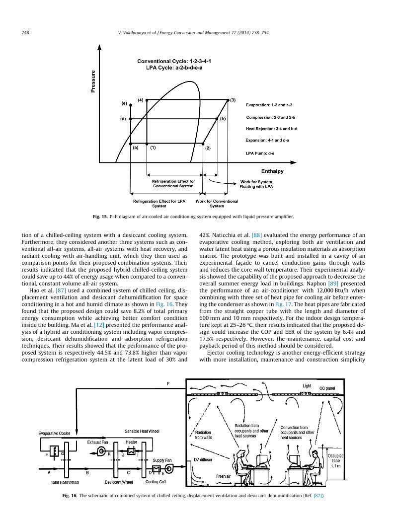
Fig. 15. P–h diagram of air-cooled air conditioning system equipped with liquid pressure amplifier.
748 V. Vakiloroaya et al. / Energy Conversion and Management 77 (2014) 738–754
tion of a chilled-ceiling system with a desiccant cooling system.Furthermore, they considered another three systems such as con-ventional all-air systems, all-air systems with heat recovery, andradiant cooling with air-handling unit, which they then used ascomparison points for their proposed combination systems. Theirresults indicated that the proposed hybrid chilled-ceiling systemcould save up to 44% of energy usage when compared to a conven-tional, constant volume all-air system.
Hao et al. [87] used a combined system of chilled ceiling, dis-placement ventilation and desiccant dehumidification for spaceconditioning in a hot and humid climate as shown in Fig. 16. Theyfound that the proposed design could save 8.2% of total primaryenergy consumption while achieving better comfort conditioninside the building. Ma et al. [12] presented the performance anal-ysis of a hybrid air conditioning system including vapor compres-sion, desiccant dehumidification and adsorption refrigerationtechniques. Their results showed that the performance of the pro-posed system is respectively 44.5% and 73.8% higher than vaporcompression refrigeration system at the latent load of 30% and
Fig. 16. The schematic of combined system of chilled ceiling, displa
42%. Naticchia et al. [88] evaluated the energy performance of anevaporative cooling method, exploring both air ventilation andwater latent heat using a porous insulation materials as absorptionmatrix. The prototype was built and installed in a cavity of anexperimental façade to cancel conduction gains through wallsand reduces the core wall temperature. Their experimental analy-sis showed the capability of the proposed approach to decrease theoverall summer energy load in buildings. Naphon [89] presentedthe performance of an air-conditioner with 12,000 Btu/h whencombining with three set of heat pipe for cooling air before enter-ing the condenser as shown in Fig. 17. The heat pipes are fabricatedfrom the straight copper tube with the length and diameter of600 mm and 10 mm respectively. For the indoor design tempera-ture kept at 25–26 �C, their results indicated that the proposed de-sign could increase the COP and EER of the system by 6.4% and17.5% respectively. However, the maintenance, capital cost andpayback period of this method should be considered.
Ejector cooling technology is another energy-efficient strategywith more installation, maintenance and construction simplicity
cement ventilation and desiccant dehumidification (Ref. [87]).

Fig. 17. Left: Schematic diagram of the air conditioner with heat pipe for cooling air in the condenser, Right: Schematic diagram of the heat pipe set and condenser unit withheat pipe set. (Ref. [89]).
V. Vakiloroaya et al. / Energy Conversion and Management 77 (2014) 738–754 749
than conventional vapor compression refrigeration systems. In anejector refrigeration system the compression may be obtainedwithout using mechanical energy [90]. The development trendand history of this technique has been investigated by Elbel andHrnjak [91]. In a heat pump system, the ejector takes the placeof the electrically driven compressor, but uses heat rather thanelectricity to produce the compression effect. This system usuallyneeds a heat source with the temperature more than 80 �C. Com-pared with vapor compression systems, the ejector cooling sys-tems have lower COP [92]. Guo and Shen [93] presented adynamic model for investigating the performance of a solar-drivenejector refrigeration plant for an office building. Their results dem-onstrated that the proposed system could conserve more than 75%of electricity compared with traditional compressor based air con-ditioner. Zhu and Jiang [94] combined a vapor compression refrig-eration cycle with an ejector cooling cycle which is demonstratedin Fig. 18. The ejector cooling system was driven by the waste heatfrom the condenser of the vapor compression system. The coolingcapacity obtained from the ejector cycle was directly fed into theevaporator of the vapor compression cycle. They found that theCOP of the hybrid system can be significantly increased when thecompressor discharge temperature is larger than 100 �C. Resultsindicated an increase of 5.5% and 8.6% for hybrid system averageCOP with R152a and R22 respectively while the average COP in-crease of hybrid system with R134a was 0.7% due to its low com-pressor discharge temperature.
Li and Zhao [95] analyzed the indoor air temperature distribu-tion of gravity air-conditioning system. In this system, several
Fig. 18. Schematic view of the vapor compression refrigeration system with theintegrated ejector cooling cycle (Ref. [94]).
plastic capillary tube nets are connected to the supply and returnwater system which is supported by a chiller. Supply water tem-perature is controlled in rang of 8–14 �C. Air is then enteredthrough the inlet at the top of the tube nets and left the coolingsystem to the room. Results demonstrated that the room tempera-ture is about 23–28 �C which means the system can provide the re-quired room cooling demand. Fasiuddin and Budaiwi [96]investigated the impact of different HVAC system strategies onenergy conservation in a commercial building in Dhahran, SaudiArabia. Their results demonstrated that using variable air volume(VAV) system instead of unitary system could save energy around22%. Also they found that an increase in indoor temperature by 3 �Cresults in 17% of saving. Modifying the fan operation schedule gavesaving about 21.4%. The use of 28 �C set point temperature duringunoccupied periods resulted in 18% saving. However, they con-cluded that energy saving of about 25% can be achieved in combi-nation of different HVAC operation strategies. Hu and Tsao [97]compared five different HVAC designs including recirculation airunit (RCU), combination of RCU with make-up air unit (MAU),combination of RCU, MAU and fan-coil unit (FCU), combinationof MAU and axial fan system and combination of MAU with fan-fil-ter unit (FFU) for a typical 200 mm wafer fabrication plant. Theyfound that the most efficient system is the combination of MAUand FFU system. Also results showed that bypassing return air tomix with make-up air can considerably reduce the energyconsumption of the RCU system. Bojic et al. [98] investigated threedifferent systems for space heating and cooling of an office build-ing as: (1) a system with a natural gas boiler and convective base-board hears for water space heating and window air conditionersfor air space cooling, (2) a system with a natural gas boiler andindividual air heaters for air space heating and a chiller plant forair space cooling and (3) an air-to-air heat pump for air space heat-ing and cooling. Simulation results showed that the first investi-gated system has the highest energy efficiency, the best economyand the lowest environmental impact. However, they mentionedthat for a complete analysis the investment costs, the maintenancecosts and other factors should be considered. Ali [99] studied thefeasibility of using naturally cooled water for human thermal com-fort inside the buildings. The water was cooled in an uninsulatedopen tank by evaporation, convection and sky radiation at nightin hot arid areas. Their experimental results for a tank having anopen surface area of 1 m2 and depth of 0.5 m showed that thewater temperature values ranged from 17.2 �C to 18.9 �C and23.8 �C to 27.1 �C can be obtained at the beginning and ends ofthe night respectively. Kilkis [100] presented a hybrid HVAC sys-tem in which a wind turbine was coupled with a convective andradiant heating and cooling system and in-space thermal energy

Fig. 19. Wind turbine driven ground source heat pump coupling to a hybrid HVAC system (Ref. [100]).
750 V. Vakiloroaya et al. / Energy Conversion and Management 77 (2014) 738–754
storage in order to satisfy the thermal loads of a 100 m2 home asdemonstrated in Fig. 19. In this design, a 6 kW wind turbine wasemployed to drive a ground source heat pump. They found thatsuch a system is more useful when the heating and cooling de-mand of the building are similar in magnitude. Sand and Fischer[101] combined a vapor compression rooftop package air condi-tioning system with an active desiccant system. The desiccant sys-tem was located after the cooling coil to dehumidify a portion ofcooled air leaving the cooling coil. This design can improve the en-ergy performance of the rooftop package when is used to precondi-tion of large amounts of outdoor air. Their simulation analysisshowed the 45% reduction in operation cost for hybrid systemcompared with the conventional rooftop package.
Using the energy management systems (EMS) can be consid-ered as another efficient method which can lead to HVAC energyusage reduction. It has been reported in several studies that adjust-ing the system variables to their optimum set-points can signifi-cantly reduce the energy consumption. Yu and Chan [102],studied how the condensing temperature control and variablechilled water flow can increase the COP of an air-cooled centrifugalchiller. They used variable speed drive for condenser fans to adjustthe condensing temperature based on the ambient temperatureand chiller load. In addition, the water flow rate of the evaporatorwas controlled to investigate its influence on the system COP. Theyfound that by controlling the condensing temperature and evapo-rator water flow rate, the COP of the system can increase by 0.8–191.7% depending on cooling load profile and ambient conditions.Chen and Deng [103] investigated the effect of a direct-digital-con-trol (DDC) based capacity controller on a variable air volume (VAV)air conditioning system. The controller regulates the compressorspeed to enhance the performance of the system. The controllerwas programmed using the real-time monitored operating data.Their results demonstrated that the desired supply air temperatureset-points can be achieved by using this method which reduces thetotal electricity usage of the system. Vakiloroaya et al. [104] pre-sented a comprehensive refinement of system optimization ofair-cooled direct expansion refrigeration systems for commercialbuildings to address the energy saving problem. They used an ac-tual DX rooftop package of a commercial building in the hot anddry climate condition for experimentation and data collection.The optimal supply air temperature and refrigerant flow rate were
calculated based on the cooling load and ambient dry-bulb tem-perature profiles. Optimization was performed by using empiri-cally-based models of the refrigeration system components forenergy savings. Their results were showed about 9% saving of theaverage power consumption. Lee et al. [105] developed and imple-mented an energy management system (EMS) for a series of cen-trifugal chillers. The EMS system was able to reduce the totalannual electricity consumption of the chillers by 23.2%. Plessiset al. [106] developed an energy management system for a deep-mine cooling system. The energy management system was con-sisted of a supervisory controller which optimized the variableset-points of the real-time system component. Their energy man-agement system led to an average electrical energy saving of 33.3%.
8. Effect of building behavior
The energy consumption of an HVAC system depends not onlyon its performance and operational parameters, but also on thecharacteristics of the heating and cooling demand and the thermo-dynamic behavior of the building. The actual load of the HVAC sys-tems is less than it is designed in most operating periods due tobuilding behavior [107]. Therefore, the most important factors thatcontribute to HVAC energy usage reduction in a given building isproper control of the heating and cooling demand [108]. Integratedcontrol of building cooling load components, such as solar radia-tion, lighting and fresh air, can result in significant energy savingsin a building’s cooling plant. It is estimated that around 70% of en-ergy savings is possible through the use of better design technolo-gies to coordinate the building demand with its HVAC systemcapacity [109]. Korolija et al. [110] investigated the relationshipbetween building heating and cooling load and subsequent energyusage with different HVAC systems. Their results indicated that thebuilding energy performance cannot be evaluated only based onbuilding heating and cooling demand due to its dependency onHVAC thermal characteristics. Huang et al. [111] developed andevaluated five energy management control functions programmedaccording to the building behavior and implemented for a variableair volume HVAC system. Their simulation results demonstratedthat energy saving of 17% can be achieved when the system isoperated with these control functions. Tzempelikos and Athienitis[112] presented the simultaneous impact of glazing area and shad-

Table 1Comparison of different HVAC energy saving strategies.
System type Capital cost Advantages Disadvantages Application Projected improvement
Direct evaporative cooling (DEC) systems They are among the very cheap airconditioning systems
Reduction of pollution emissions/life cycle cost effectiveness/reduction of peak demand
Cannot effectively work when ambientrelative humidity if higher than 40%
When comfortconditions arenot target
Their performance can besignificantly improved usingseveral approaches
In direct evaporative cooling (IEC) systems Their running and capital cost is higherthan DEC systems but lower than vaporcompression air conditioning systems
Their air quality is considerablyhigher than DEC/More energyefficient compared with vaporcompression refrigeration systems
Their installation and operation are morecomplex than DEC systems
All buildings Still there are severalopportunities to improvetheir performance
Evaporative-cooled air conditioningsystems
Water usage cost is increased whileelectricity usage cost is reduced. In total,this method add less cost than otherdiscussed methods to the air conditionsystem
Can significantly reduce the energyconsumption of the air conditioningsystem in peak demand conditions
Their energy saving potential is limited toa period that ambient temperature ishigh
Can be appliedon air-cooledvaporcompression airconditioningsystems
Control methods can reducethe water usage of theevaporative-cooledcondenser
Liquid pressure amplification (LPA)systems
More expensive than conventional vaporcompression refrigeration systems butcheaper than thermal storage, heatrecovery, ground-coupled and desiccantcooling systems
Results in significant energy savingsfor vapor compression refrigerationsystems whilst provides reasonabletimeframe payback of theadditional costs
Their energy saving potential is limited toa period that ambient temperature fallsto low temperature
Can be appliedon air-cooledvaporcompression airconditioningsystems
This method can be appliedin more air-cooled vaporcompression air conditioningsystems in operation todayworldwide
Thermal storage systems Expensive in both capital and runningcost
They significantly reduce theelectric energy cost/Requiredsmaller ducting system thanconventional air systems
Their coefficient of performance is lessthan conventional vapor compression airconditioners
Buildings withhigh cooling,short durationdemands
Robust control method canenhance the efficiency of thissystem
Heat recovery systems Expensive in both capital and runningcost
Highly Energy Efficient intemperate climates
Larger than conventional air-handlingunits
Commercialbuildings
Their dimension can bereduced by increasing theefficiency of heat recoverydevices
Ground-coupled systems Expensive in both capital and runningcost
Compared with standard vaporcompression systems, this systemcreates less noise and reducesgreenhouse gas emissions
requirements of deep below the earth’ssurface/Very high upfront costs
Residential andcommercialbuildings
Investigations should bedone to optimize theinstallation method and cost
Chilled-ceiling systems Reasonable timeframe payback of theadditional costs
They require cooled water insteadof chilled water which lead to lessrefrigeration
Are unable to moderate indoor humidity/Risk of condensation at cold surface
Public buildings More study are required toreduce the risk ofcondensation using newmaterials
Desiccant cooling systems Expensive in both capital and runningcost
When used in conjunction withconventional air conditioningsystems, humidity control isimproved
Some desiccants are corrosive/Responsetime is relatively large/Crystallizationmay be a problem
CommercialBuildings/Supermarket
This system can graduallyattain wider marketpenetration
Ejector cooling systems Reasonable timeframe payback of theadditional costs
More installation, maintenance andconstruction simplicity thanconventional vapor compressionrefrigeration systems
This system needs a heat source with thetemperature more than 80 �C/Comparedwith conventional vapor compressionsystems, the ejector cooling systems havelower COP
When enoughheat sourcetemperature isavailable
Studies should be carried outto enhance the coefficient ofperformance of this system
Variable refrigerant flow (VRF) systems Expensive in both capital and runningcost
Efficient in part load conditions Required extra control systems/Cannotprovide full control of humidity
Residential andcommercialbuildings
Several efforts are currentlycarrying out to enhance theperformance of this system
V.V
akiloroayaet
al./EnergyConversion
andM
anagement
77(2014)
738–754
751

752 V. Vakiloroaya et al. / Energy Conversion and Management 77 (2014) 738–754
ing control on building cooling and lighting demand using a cou-pled lighting and thermal simulation module. The simulation re-sults showed that the integrated control of motorized shadingand electric lighting systems could reduce the building energy de-mand. Sun et al. [113] proposed a methodology to get a near-opti-mal strategy for controlling the shading blinds, natural ventilation,lights and HVAC system jointly but they did not consider the realmonitored data for HVAC system to survey the influence of theirproposed integrated control on the HVAC energy saving potential.Kim et al. [114] investigated the influence of manual and auto-mated blinds on the both cooling energy consumption and thermalcomfort. Their study showed that in terms of cooling energy usage,automated blinds reduce the required cooling demand comparedto manual blinds which are fully opened while the automatedblinds can block the solar radiation according to the ambientconditions.
9. Discussion
Energy-efficient HVAC system designs depend on new configu-rations of traditional systems that make better use of existingparts. One effective way of achieving energy efficiency has beenthe design of HVAC system configurations that combine a rangeof different traditional HVAC system components. Recent researchhas demonstrated that a combination of existing air conditioningtechnologies can offer effective solutions for energy conservationand thermal comfort [109]. Each HVAC discipline has specific de-sign requirements and each presents opportunities for energy sav-ings. It must be understood, however, that different configurationsin one area may augment or diminish savings in another. Forexample, a new configuration might improve system performanceand thus raise its energy saving potential, but this raises the up-front cost of the system. Consequently, it is important that theuse of a new configured system results in electricity savings thatare large enough to pay back initial investments in a suitably shorttime. In this regard, a newly-developed system that can heat andcool at low cost is very desirable because of the increased financialsavings on offer. The literature shows that a blend of air condition-ing technologies can offer effective solutions for energy conserva-tion and thermal comfort. The main aim of this comparisonstudy between various types of HVAC systems is to find the opti-mum configuration for air conditioning systems that provide max-imum cooling performance while minimizing electrical powerconsumption, with a view to slowing the rampant growth of dailypeak demand on the electricity grid in summer. In this regard, thearchitectural limitations of the building must be taken into ac-count. This would reduce the number of possible HVAC systemsthat are suitable for installation in a commercial or residentialbuilding. Additionally, climatic conditions may influence the finalsystem selection. In vapor compression air conditioning systems,the water-cooled units have a higher COP than air-cooled unitsdue to their lower refrigerant condensing temperature [115]. How-ever, since the performance of cooling tower as the main part ofwater-cooled systems is highly dependent on ambient relativehumidity, then water-cooled air conditioning systems cannot beused in areas with high ambient relative humidity. It has been esti-mated that the efficiency of evaporative cooling system such ascooling tower and air washers is significantly increased when theambient relative humidity is lower than approximately 40%[116]. However, in dry regions, evaporative cooling systems cancut the electricity consumption of the vapor compression systemsas discussed in the study. Furthermore, when lower comfort condi-tions are required, then using the evaporative cooling system aloneis an appropriate selection. However, evaporative cooling systemsrequire 100% outdoor air and exhaust capability and thus the cost
of equipment area, filter capacity and air delivery must be weighedagainst the energy savings of evaporative cooling versus refrigera-tion cooling.
Another issue that drastically increases the energy usage ofHVAC systems is the requirement for fresh air in the buildings theycool. The amount of fresh air for a building is dependent on thetype of activities taking place in the building. However, in the casethat a building needs more fresh air to produce positive pressureinside the space, using a heat recovery system is the best option.For buildings with lower fresh air level quotas, controlling andadjusting the fresh air flow rates based on design criteria is a moreefficient method. Thermal storage systems are appropriate whenmaximum cooling load is significantly higher than average load.Therefore, these systems are normally used for commercial andindustrial buildings but have fewer benefits in residential build-ings. Among the buildings most suited to thermal storage systemsare buildings with high cooling, short duration demands. Althoughcapital costs for this sort of systems tend to be higher than a con-ventional system, but smaller ducting system for the thermal stor-age system can compensation that additional cost. While thissystem has higher upfront costs, its reduced energy usage will re-sult in significant long-term savings as a result of lower energybills. A ground-source heat pump takes advantage of more benignclimates belowground, limiting the efficacy of this sort of systemfor aboveground installations. Furthermore, other factors such asmaintenance and cost of repairs would cost more compared toother HVAC systems. Determining the most appropriate HVAC sys-tem option for a given building is a complex exercise that requiresdetailed analysis of cost and energy savings and offsets, as well as aholistic analysis of various internal and external factors. Perhaps,one strategy is suitable for summer while it is not energy-efficientfor winter. In this case, choosing individual systems for summerand winter should be analyzed to give the optimum solution.Although due to practical matters, considering all of these factorssimultaneously is difficult, but a designer should heed and exploitthe best energy reduction strategies by attending all technically,economically and applicability facts. However, all of discussedmethods in this study can be retrofitted to the existing conven-tional HVAC system. The cost, advantages, disadvantages, applica-tion and projected improvement of all aforementioned strategieshave been summarized in Table 1.
10. Conclusion
Conventional HVAC systems rely heavily on energy generatedfrom fossil fuels, which are being rapidly depleted. This togetherwith a growing demand for cost-effective infrastructure and appli-ances has necessitated new installations and major retrofits inoccupied buildings to achieve energy efficiency and environmentalsustainability. Therefore, finding novel ways towards green build-ings without compromising comfort and indoor air quality remainsa challenge for research and development. The overall attainablereduction in energy consumption and enhancement of humancomfort in the buildings are dependent on the performance ofHVAC systems. One proven way of achieving energy efficiency inHVAC systems is to design systems that use novel configurationsof existing system components. Recent research has demonstratedthat a combination of existing air conditioning technologies can of-fer effective solutions for energy conservation and thermal com-fort. In this paper various energy saving strategies for HVACsystems were investigated and their potential to improve the sys-tem performance were discussed. It was found that several factorssuch as climatic conditions, expected thermal comfort, initial andcapital cost, the availability of energy sources and the application

V. Vakiloroaya et al. / Energy Conversion and Management 77 (2014) 738–754 753
of the building must be considered to properly design and select anenergy-efficient HVAC system.
References
[1] Enteria N, Mizutani K. The role of the thermally activated desiccant coolingtechnologies in the issue of energy and environment. Renew Sustain EnergyRev 2011;15:2095–122.
[2] Qi R, Lu L, Yang H. Investigation on air-conditioning load profile and energyconsumption of desiccant cooling system for commercial buildings in HongKong. Energy Build 2012;49:509–18.
[3] Perez-lombard L, Ortiz J, Pout C. A review on buildings energy consumptioninformation. Energy Build 2008;40:394–8.
[4] Yao Y, Chen J. Global optimization of a central air-conditioning system usingdecomposition–coordination method. Energy Build 2010;42:570–83.
[5] Balaras CA, Grossman G, Henning H, Ferreira CAI, Podesser E, Wang L, et al.Solar air conditioning in Europe – an overview. Renew Sustain Energy Rev2007;11:299–314.
[6] Australian Greenhouse Office. Australian Commercial Building Sector Green-House Gas Emission. AGO, Canberra, Australia; 1990–2010.
[7] Energy Conversation Building Code (ECBC). Bureau of Energy Efficiency,Ministry of Power, Government of India; 2007.
[8] Fong KF, Chow TT, Lee CK, Lin Z, Chan LS. Comparative study of different solarcooling systems for buildings in subtropical city. Sol Energy 2010;84:227–44.
[9] El-Dessouky H, Ettouney H, Al-Zeefari A. Performance analysis of two-stageevaporative coolers. Chem Eng J 2004;102:255–66.
[10] IEO, International Energy Outlook (IEO), Energy Information Administration.<http://www.eia.doe.gov/oiaf/ieo>.
[11] Desideri U, Proietti S, Sdringola P. Solar-powered cooling system: technicaland economic analysis on industrial refrigeration and air-conditioningapplications. Appl Energy 2009;86:1376–86.
[12] Ma Q, Wang RZ, Dai YJ, Zhai XQ. Performance analysis on a hybrid airconditioning system of a green building. Energy Build 2006;38:447–53.
[13] ANSI/ASHRAE Standard 55–2004. Thermal Environmental Conditions forHuman Occupancy, American Society of Heating Ventilating and AirConditioning Engineers, Atlanta, GA, USA; 2004.
[14] ISO Standard 7730. Moderate Thermal Environment, Determination of PMVand PPD Indices and Specifications of the Conditions for Thermal Comfort.International Organization for Standardization, Geneva, Switzerland; 2005.
[15] Ma Z, Wang S, Xu X, Xiao F. A supervisory control strategy for building coolingwater systems for practical and real time applications. Energy ConversManage 2008;49:2324–36.
[16] Vakiloroaya V, Ha QP, Samali B. Energy-efficient HVAC systems: simulation-empirical modelling and gradient optimization. Automat Constr2013;31:176–85.
[17] Jiang Y, Xie X. Theoretical and testing performance of an innovative indirectevaporative chiller. Sol Energy 2010;84:2041–55.
[18] Khalajzadeh V, Farahani MF, Heidarnejad G. A novel integrated system ofground heat exchanger and indirect evaporative cooler. Energy Build2012;49:604–10.
[19] Vakiloroaya V, Khatibi M, Ha QP, Samali B. New integrated hybrid evaporativecooling system for HVAC energy efficiency improvement. IEEE/SICEinternational symposium on system integration, Kyoto, Japan; 2011. p.591–6.
[20] Khandelwal A, Talukdar P, Jain S. Energy savings in a building usingregenerative evaporative cooling. Energy Build 2011;43:581–91.
[21] Lahoti U, Jain S, Kaushik V, Dhar PL. A novel air cooler. Internationalconference on emerging technologies in air conditioning and refrigeration,New Delhi, India; 2001. p. 250–8.
[22] Heidarnejad G, Farahani MF, Delfani S. Investigated of a hybrid system ofnocturnal radiative cooling and direct evaporative cooling. Build Environ2010;45:1521–8.
[23] Kumar S, Riangvilaikul B. An experimental study of a novel dew pointevaporative cooling system. Energy Build 2010;42:637–44.
[24] Delfani S, Esmaeelian J, Pasdarshahri H, Karami M. Energy saving potential ofan indirect evaporative cooler as a pre-cooling unit for mechanical coolingsystem in Iran. Energy Build 2010;42:2169–76.
[25] Hajidavalloo E, Eghtedari H. Performance improvement of air-cooledrefrigeration system by using evaporatively cooled air condenser. Int JRefrig 2010;33:982–8.
[26] Youbi-Idrissi M, Macchi-Tejeda H, Fournaison L, Guilpart J. Numerical modelof sprayed air cooled condenser coupled to refrigeration system. EnergyConvers Manage 2007;48:1943–51.
[27] Jahangeer KA, Tay AAO, Islam MDR. Numerical investigation of transfercoefficient of an evaporatively-cooled condenser. Appl Therm Eng2011;31:1655–63.
[28] Yu FW, Chan KT. Improved energy performance of air-cooled chiller systemwith mist pre-cooling mist improvement on air-cooled chiller. Appl ThermEng 2011;31:537–44.
[29] Vrachopoulos M, Filios AE, Kotsiovelos GT, Kravvaritis ED. Incorporatedevaporative condenser. Appl Therm Eng 2007;27:823–8.
[30] Hwang Y, Radermacher R, Kopko W. An experimental evaluation of aresidential-sized evaporatively cooled condenser. Int J Refrig2001;24:238–49.
[31] Omer AM. Ground-source heat pumps systems and applications. RenewSustain Energy Rev 2008;12:344–71.
[32] Zogou O, Stamatelos A. Effect of climate conditions on the performance ofheat pump systems for space heating and cooling. Energy Convers Manage1998;39:609–22.
[33] Hwang Y, Lee JK, Jeong YM, Koo KM, Lee DH, Kim SW, et al. Coolingperformance of a vertical ground-coupled heat pump system installed in aschool building. Renewable Energy 2009;34:578–82.
[34] Yang Y, Zhai XQ. Experience on the application of a ground source heat pumpsystem in an archives building. Energy Build 2011;43:3263–70.
[35] Hackel S, Pertzborn A. Effective design and operation of hybrid ground-sourceheat pumps: three case studies. Energy Build 2011;43:3497–504.
[36] Hepbasli A, Akdemir O, Hancioglu E. Experimental study of a closed loopvertical ground source heat pump system. Energy Convers Manage2003;44:527–48.
[37] Agyenim F, Hewitt N. The development of a finned phase change material(PMC) storage system to take advantage of off-peak electricity tariff forimprovement cost of heat pump operation. Energy Build 2010;42:1552–60.
[38] Long J, Zhu D. Numerical and experimental study on heat pump water heaterwith PMC for thermal storage. Energy Build 2008;40:666–72.
[39] Spitler JD. Ground-source heat pump research- past, present and future.HVAC&R Res 2005;11:165–7.
[40] Lee JY. Current status of ground source heat pumps in Korea. Renew SustainEnergy Rev 2009;13:1560–8.
[41] Gao Q, Li M, Yu M, Spitler JD, Yan YY. Review of development from GSHP toUTES in China and other countries. Renew Sustain Energy Rev2009;13:1383–94.
[42] Yang W, Zhou J, Xu W, Zhang G. Current status of ground-source heat pumpsin china. Energy Policy 2010;38:323–32.
[43] Pardo N, Montero A, Sala A, Martos J, Urchueguia JF. Efficiency improvementof a ground coupled heat pump system from energy management. ApplTherm Eng 2011;31:391–8.
[44] Magraner T, Montero A, Quilis S, Urcheguia JF. Comparison between designand actual energy performance of a HVAC-ground coupled heat pump systemin cooling and heating operation. Energy Build 2010;42:1394–401.
[45] Pardo N, Montero A, Martos J, Urchueguia JF. Optimization of hybrid-groundcoupled and air source-heat pump systems in combination with thermalstorage. Appl Therm Eng 2010;30:1073–7.
[46] Jeon J, Lee S, Hong D, Kim Y. Performance evaluation and modeling of a hybridcooling system combining a screw chiller with a ground source heat pump ina building. Energy 2010;35:2006–12.
[47] Gasparella A, Longo GA, Marra R. Combination of ground source heat pumpswith chemical dehumidification of air. Appl Therm Eng 2005:295–308.
[48] Park H, Lee JS, Kim W, Kim Y. Performance optimization of a hybrid groundsource heat pump with the parallel configuration of a ground heat exchangerand a supplemental heat rejecter in the cooling mode. Int J Refrig2012;35:1357–546.
[49] Inalli M, Esen H. Experimental thermal performance evaluation of ahorizontal ground-source heat pump system. Appl Therm Eng2004;24:2219–32.
[50] Bakirci K, Colak D. Effect of superheating and sub-cooling heat exchanger tothe performance of a ground source heat pump system. Energy2012;44:996–1004.
[51] Lam HN, Lee CK. Computer simulation of ground source-coupled liquiddesiccant air conditioner for sub-tropical regions. Int J Therm Sci2009;48:2365–74.
[52] Zhao J, Li C. Experimental study on indoor air temperature distribution ofgravity air-conditioning for cooling. Energy Proc 2012;17:961–7.
[53] Rahman MM, Rasul MG, Khan MMK. Feasibility of thermal energy storagesystem in an institutional building in subtropical climates in Australia. ApplTherm Eng 2011;31:2943–50.
[54] Yau YH, Rismanchi B. A review on cool thermal storage technologies andoperating strategies. Renew Sustain Energy Rev 2012;16:787–97.
[55] Al-Abidi AA, Mat SB, Sopian K, Sulaiman MY, Lim CH, Th A. Review of thermalenergy storage for air conditioning systems. Renew Sustain Energy Rev2012;16:5802–19.
[56] Ezan MA, Erek A, Dincer I. Energy and exergy analysis of an ice-on-ice thermalenergy storage system. Energy 2011;36:6375–86.
[57] Pu J, Liu G, Feng X. Cumulative exergy analysis of ice thermal storage airconditioning system. Appl Energy 2012;93:564–9.
[58] Hasnain SM, Alabbadi NM. Need for thermal-storage air-conditioning inSaudi Arabia. Appl Energy 2000;65:153–64.
[59] Chaichana C, Charters WWS, Aye L. An ice thermal storage computer model.Appl Therm Eng 2001;21:1769–78.
[60] Wang X, Niu J, Paassen AHCV. Raising evaporative cooling potential usingcombined cooled ceiling and MPCM slurry storage. Energy Build2008;40:1691–8.
[61] Sehar F, Rahman S, Pipattanasomporn M. Impacts of ice storage on electricalenergy consumption in office buildings. Energy Build 2012;51:255–62.
[62] Sebzali MJ, Ameer B, Hussain HJ. Economic assessment of chilled waterthermal storage and conventional air-conditioning systems. Energy Proc2012;18:1485–95.
[63] Sebzali MJ, Rubini PA. Analysis of ice cool thermal storage for a clinic buildingin Kuwait. Energy Convers Manage 2006;47:3417–34.

754 V. Vakiloroaya et al. / Energy Conversion and Management 77 (2014) 738–754
[64] ASHRAE Handbook-HVAC systems and equipment. American Society ofHeating, Refrigerating and Air-Conditioning Engineers, Atlanta, GA, USA;2008.
[65] Stritih U, Butala V. Experimental investigation of energy saving in buildingswith PCM cold storage. Int J Refrig 2010;33:1676–83.
[66] Nagano K, Takeda S, Mochida T, Shimakura K, Nakamura T. Study of a floorsupply air conditioning system using granular phase change material toaugment building mass thermal storage-Heat response in small scaleexperiments. Energy Build 2006;38:436–46.
[67] Huang MC, Chen BR, Hsiao MJ, Chen SL. Application of thermal battery in theice storage air-conditioning system as a subcooler. Int J Refrig2007;30:245–53.
[68] Matsuki N, Nakano Y, Miyanaga T, Yokoo N, Oka T. Performance of radiantcooling system integrated with ice storage. Energy Build 1999;30:177–83.
[69] Stoecker WF, Jones JW. Refrigeration and air conditioning. NewYork: McGraw-Hill; 1982.
[70] Roulet CA, Heidt FD, Foradini F, Pibiri MC. Real heat recovery with airhandling units. Energy Build 2001;33:495–502.
[71] Manz H, Huber H. Experimental and numerical study of a duct/heatexchanger unit for building ventilation. Energy Build 2000;32:189–96.
[72] Zhang LZ. Progress on heat and moisture recovery with membranes: Fromfundamentals to engineering applications. Energy Convers Manage2012;63:173–95.
[73] Zhang LZ, Niu JL. Energy requirements for conditioning fresh air and the long-term savings with a membrane-based energy recovery ventilator in HongKong. Energy 2001;26:119–35.
[74] Ke Z, Yaming K. Applicability of air-to-air heat recovery ventilators in China.Appl Therm Eng 2009;29:830–40.
[75] Nasif M, Al-Waked R, Morrison G, Behnia M. Membrane heat exchanger inHVAC energy recovery systems, systems energy analysis. Energy Build2010;42:1833–40.
[76] Fernandez-Seara J, Diz R, Uhia FJ, Dopazo A, Ferro JM. Experimental analysisof an air-to-air heat recovery unit for balanced ventilation systems inresidential buildings. Energy Convers Manage 2011;52:635–40.
[77] Rasouli M, Simonson CJ, Besant RW. Applicability and optimum controlstrategy of energy recovery ventilators in different climatic conditions.Energy Build 2010;42:1376–85.
[78] Delfani S, Pasdarshahri H, Karami M. Experimental investigation of heatrecovery system for building air conditioning in hot and humid areas. EnergyBuild 2012;49:62–8.
[79] Wallin J, Madani H, Claesson J. Run-around coil ventilation heat recoverysystem: A comparative study between different system configurations. ApplEnergy 2012;90:258–65.
[80] Martinez FJR, Plasencia MAAG, Gomez EVG, Diez FV, Martin RH. Design andexperimental study of a mixed energy recovery system, heat pips and indirectevaporative equipment for air conditioning. Energy Build 2003;35:1021–30.
[81] Mahmud K, Mahmood GI, Simonson CJ, Besant RW. Performance testing of acounter-cross-flow run-around membrane energy exchanger (RAMEE)system for HVAC applications. Energy Build 2010;42:1139–47.
[82] Vakiloroaya V, Ha QP, Skibniewski M. Modeling and Experimental Validationof a Solar-Assisted Direct Expansion Air Conditioning System. Energy Build2013;66:524–36.
[83] Vakiloroaya V, Madadnia J, Samali B. Modeling and performance prediction ofan integrated central cooling plant for HVAC energy efficiency improvement.Build Simul: Int J 2013;6:127–38.
[84] Al-Rabghi OM, Akyurt MM. A survey of energy efficient strategies for effectiveair conditioning. Energy Convers Manage 2004;45:1643–54.
[85] Fauchoux M, Bansal M, Talukdar P, Simonson CJ, Torvi D. Testing andmodeling of a novel ceiling panel for maintaining space relative humidity bymoisture transfer. Int J Heat Mass Transf 2010;53:3961–8.
[86] Niu JL, Zhang LZ, Zuo HG. Energy savings potential of chilled-ceilingcombined with desiccant cooling in hot and humid climates. Energy Build2002;34:487–95.
[87] Hao X, Zhang G, Chen Y, Zou S, Moschandreas DJ. A combined system ofchilled ceiling, displacement ventilation and desiccant dehumidification.Build Environ 2007;42:3298–308.
[88] Naticchia B, Dorazio M, Carbonari A, Persico I. Energy performance evaluationof a novel evaporative cooling technique. Energy Build 2010;42:1926–38.
[89] Naphon P. On the performance of air conditioner with heat pipe for coolingair in the condenser. Energy Convers Manage 2010;51:2362–6.
[90] Chen X, Omer S, Worall M, Riffat S. Recent developments in ejectorrefrigeration technologies. Renew Sustain Energy Rev 2013;19:629–51.
[91] Elbel S, Hrnjak P. Ejector refrigeration: an overview of historical and presentdevelopments with an emphasis on air-conditioning applications.International refrigeration and air conditioning conference, Purdue, USA;July 14-17, 2008.
[92] Cardemil JM, Colle S. A general model for evaluation of vapor ejectorsperformance for application in refrigeration. Energy Convers Manage2012;64:79–86.
[93] Guo J, Shen HG. Modeling solar-driven ejector refrigeration system offeringair conditioning for office buildings. Energy Build. 2009;41:175–81.
[94] Zhu Y, Jiang P. Hybrid vapor compression refrigeration system with anintegrated ejector cooling cycle. Int J Refrig 2012;35:68–78.
[95] Li C, Zhao J. Experimental study on indoor air temperature distribution ofgravity air-conditioning for cooling. Energy Proc 2012;17:961–7.
[96] Fasiuddin M, Budaiwi I. HVAC system strategies for energy conversation incommercial buildings in Saudi Arabia. Energy Build 2011;43:3457–66.
[97] Hu SC, Tsao JM. A comparative study on energy consumption for HVACsystems of high-tech FABs. Appl Therm Eng 2007;27:2758–66.
[98] Bojic M, Nikolic N, Nikolic D, Skerlic J, Miletic I. A simulation appraisal ofperformance of different HVAC systems in an office building. Energy Build2011;43:1207–15.
[99] Ali AHH. Passive cooling of water at night in uninsulated open tank in hot aridareas. Energy Convers Manage 2007;48:93–100.
[100] Kilkis IB. Utilization of wind energy in space heating and cooling with hybridHVAC systems and heat pumps. Energy Build 1999;30:147–53.
[101] Sand JR, Fischer JC. Active desiccant integration with packaged rooftop HVACequipment. Appl Therm Eng 2005;25:3138–48.
[102] Yu FW, Chan KT. Improved energy performance of air cooled centrifugalchillers with variable chilled water flow. Energy Convers Manage2008;49:1595–911.
[103] Chen WU, Deng S. Research on a novel DDC-based capacity controller for thedirect-expansion variable-air-volume A/C system. Energy Convers Manage2010;51:1–8.
[104] Vakiloroaya V, Zhu JG, Ha QP. Modeling and optimization of direct expansionair conditioning systems for commercial buildings energy savings. The 28thinternational symposium on automation and robotics in construction, Seoul,Korea; 2011. p. 232–7.
[105] Lee SK, Teng MC, Fan KS, Yang KH, Horng RS. Application of an energymanagement system in combination with FMCS to high energy consuming ITindustries of Taiwan. Energy Convers Manage 2011;52:3060–70.
[106] Plessis GED, Liebenberg L, Mathews EH, Plessis JND. A versatile energymanagement system for large integrated cooling system. Energy ConversManage 2013;66:312–25.
[107] Vakiloroaya V, Samali B, Madadnia J, Ha QP. Component-wise optimisationfor commercial central cooling plant. The 37th international conference ofthe IEEE industrial electronics (IECON), Melbourne, Australia; 2011. p. 2686–91.
[108] Jin X, Du Z, Xiao X. Energy evaluation of optimal control strategies for centralVWV chiller systems. Appl Therm Eng 2007;27:934–41.
[109] Ellis MW, Mathews EH. Needs and trends in building and HVAC systemdesign tools. Build Environ 2002;37:461–70.
[110] Korolija I, Marjanovic-Halburd L, Zhang Y, Hanby VI. Influence of buildingparameters and HVAC systems coupling on building energy performance.Energy Build 2011;43:1247–53.
[111] Huang WZ, Zaheeruddin M, Cho SH. Dynamic simulation of energymanagement control functions for HVAC systems in buildings. EnergyConvers Manage 2006;47:926–43.
[112] Tzempelikos A, Athienitis AK. The impact of shading design and control onbuilding cooling and lighting demand. Sol Energy 2007;81:369–82.
[113] Sun B, Luh BL, Jia QS, Jiang Z, Wang F, Song C. An integrated control of shadingblinds, natural ventilation and HVAC system for energy saving and humancomfort. IEEE international conference of automation science andengineering, Toronto, Ontario, Canada; 2010. p. 7–14.
[114] Kim JH, Park YJ, Yeo MS, Kim KW. An experimental study on the environmentperformance of the automated blind in Summer. Build Environ2009;44:1517–27.
[115] Vakiloroaya V. Design optimization of the cooling coil for HVAC energysaving and comfort enhancement. Environ Prog Sustain Energy 2012. http://dx.doi.org/10.1002/ep.11729.
[116] Vakiloroaya V, Madadnia J. Cooling coil design improvement for HVAC energysavings and comfort enhancement. Sustain Energy Build 2013:965–74.