YASKAWA Energy-Saving Unit
33
High-Power Factor Converter with Power Regeneration (K5 = 0) YASKAWA Energy-Saving Unit D1000 200 V Class, 30 to 130 kW 400 V Class, 90 to 370 kW Certified for ISO9001 and ISO14001 JQA-EM0498 JQA-0422
-
Upload
khangminh22 -
Category
Documents
-
view
0 -
download
0
Transcript of YASKAWA Energy-Saving Unit
High-Power Factor Converter with Power Regeneration (K5=0)YASKAWA Energy-Saving Unit
D1000200 V Class, 30 to 130 kW400 V Class, 90 to 370 kW
Certified for
ISO9001 and
ISO14001
JQA-EM0498JQA-0422
Increase Your Power!Increase Your Power!
D1000D1000Energy-Saving
Triangle
AC Drive Motor
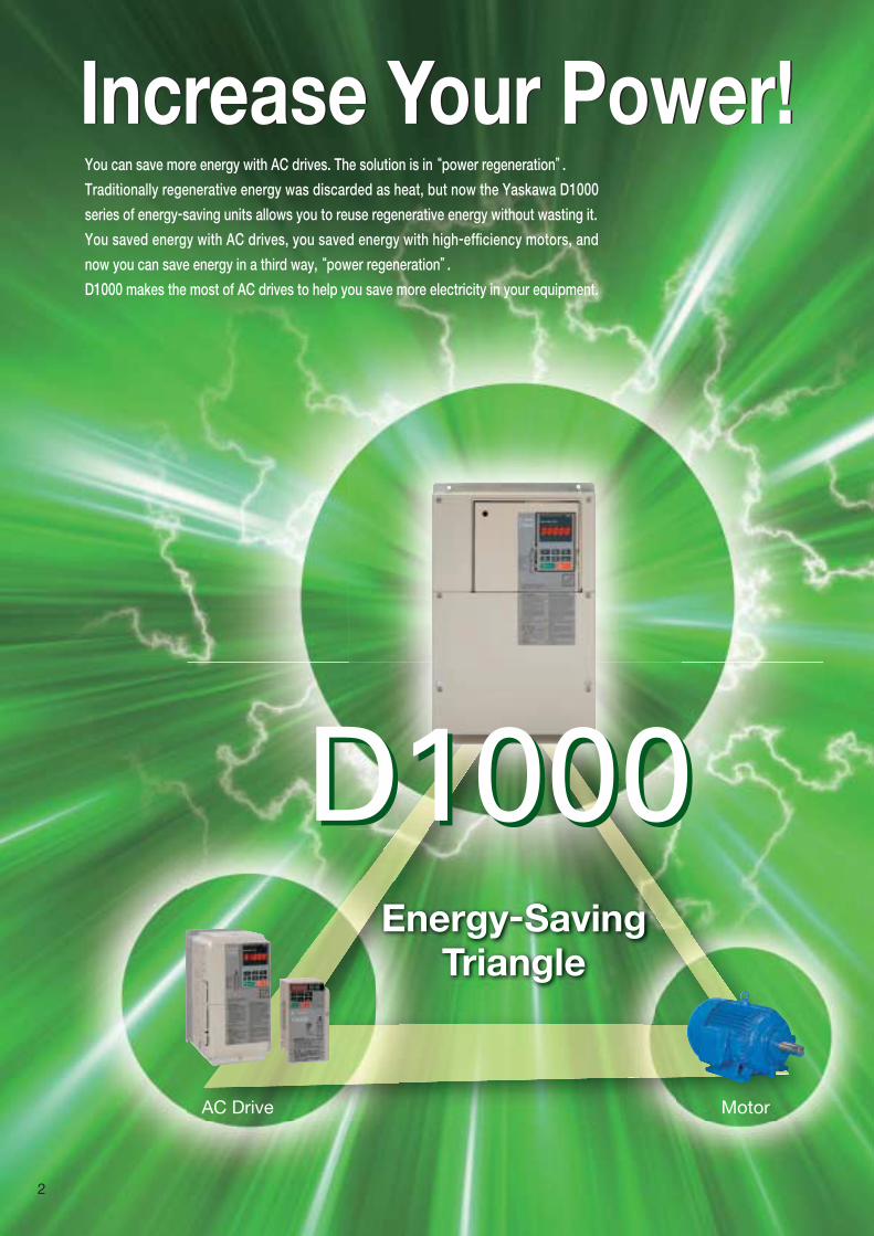
You can save more energy with AC drives. The solution is in “power regeneration”.Traditionally regenerative energy was discarded as heat, but now the Yaskawa D1000
series of energy-saving units allows you to reuse regenerative energy without wasting it.
You saved energy with AC drives, you saved energy with high-efficiency motors, and
now you can save energy in a third way, “power regeneration”. D1000 makes the most of AC drives to help you save more electricity in your equipment.
2
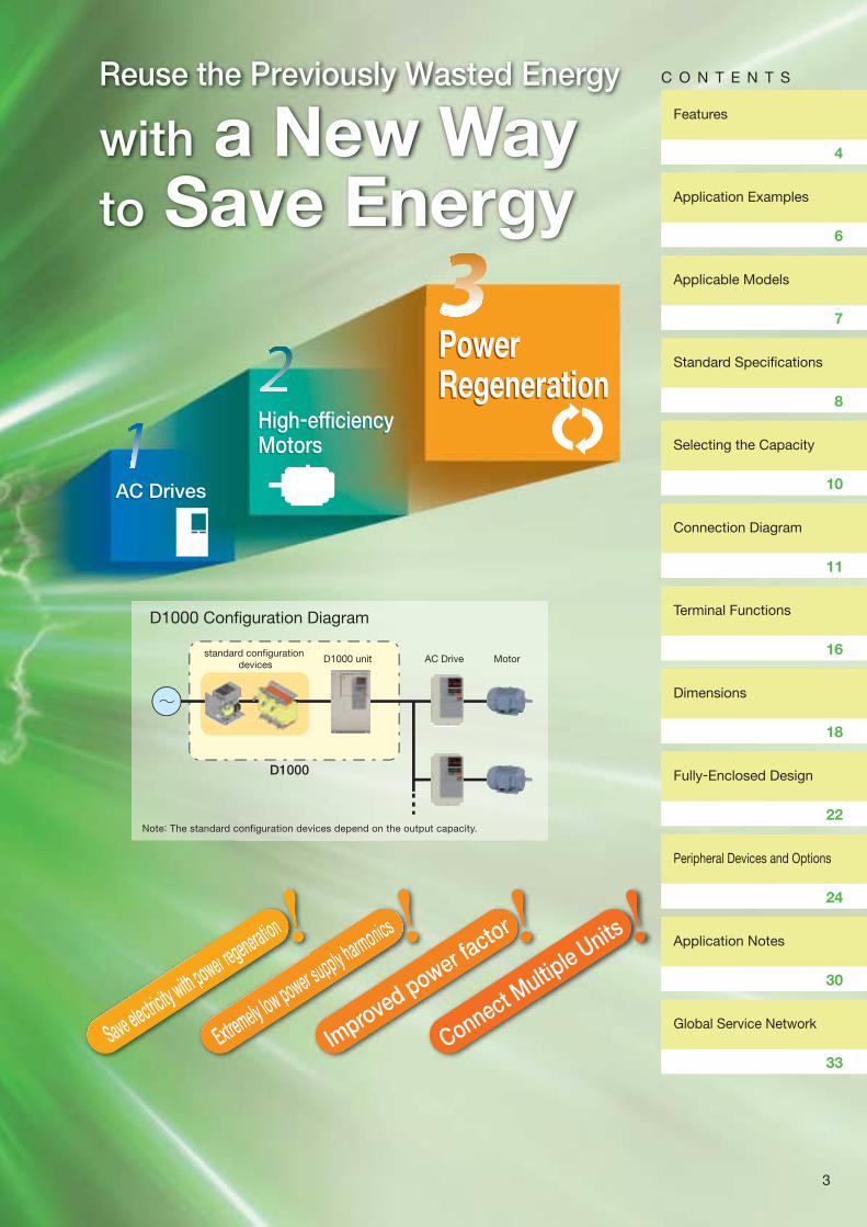
D1000 Configuration Diagram
Note: The standard configuration devices depend on the output capacity.
Reuse the Previously Wasted Energy
with a New Way to Save Energy
Save electricity with power regeneration
power regeneration
Extremely low power supply harmonics
r supply harmonics
Improved power fa
ctor
ower factor
Connect Multip
le Units
standard configuration devices
AC Drive MotorD1000 unit
D1000
AC DrivesAC Drives
High-efficiency MotorsHigh-efficiency Motors
Power RegenerationPower Regeneration
Features
Application Examples
Applicable Models
Standard Specifi cations
Selecting the Capacity
Connection Diagram
Terminal Functions
Dimensions
Fully-Enclosed Design
Peripheral Devices and Options
Application Notes
Global Service Network
4
6
7
8
10
11
16
18
22
24
30
33
C O N T E N T S
3

Let us help you improve the quality of your power.Save More EnergySave More Energy
Solve Your Harmonics IssuesSolve Your Harmonics Issues
Large power supply current distortion rate.
Power factor: Approx. 0.7
Input Power Supply Current Waveform Comparison
Standard Drive Standard Drive with D1000
Small power supply current distortion rate.
Power factor: Approx. 1.0Condition: Rated load.
D1000
Power supply energy for other devices
DriveLowering (regenerative energy)
Return Electricity with Power Regeneration
Combined with drives or servo systems, D1000 lets
you effectively use energy by returning regenerative
energy to the power supply.
There are no power supply harmonics (K5=0) and input
power supply current waveform distortion is greatly
reduced.
You can comply with harmonic suppression guidelines.
You do not need a separate harmonic compensator to
reduce harmonics to the same degree as an active filter.
You can supply a stable DC voltage to drives and servo systems
without being influenced by fluctuations in the input AC voltage.
You can greatly reduce heat loss from power
supply facilities caused by harmonics.
Supply Stable DC Voltages
You can use analog outputs
and communications
networks to easily and visually
monitor all sorts of data.
Operation is as easy as for a
Yaskawa 1000-series AC
drive. * : Available soon.
There are no power supply harmonics (K5=0) and input
No Power Supply Harmonics
Downsize Power Supply EquipmentDownsize Power Supply Equipment
Power supply power factor 1 control* and sinusoidal PWM control
enable downsizing power supply facilities, including power cables and
power receiving equipment, which greatly reduces facilities costs.
By improving the power factor, you can expand equipment without
increasing the capacity of existing power supply facilities.
Power supply power factor 1 control* and
Improved Power Factor
Energy Savings That You Can See
In equipment that uses many drives or many servos, you can
save energy by using all of the regenerative energy that you
used to waste as the energy for other equipment.
Save Energy with Regenerative Energy
Combined with drives or servrr o systems D1000 lets
Save More Electricity with Power Regeneration
You can greatly reduce heat loss from power
Reduce Wasteful Heat Loss
Save Energy with Regenerativ
Connect Multiple Units
Reduce costs
Extremely low harmonics
Compliance with Harmonic Suppression Guidelines
Power usage (kW) = √3 × V × I × cos
Power capacity (kVa) [apparent power]
Power factor
[active power]θ
Regenerative energy
is effectively returned
to the power supply.
Hoisting (drive energy)
Accumulative power pulse output*
kWh
D1000
Powerconsumption
kW
Powerfactor
%
Power saved
kW
Power bill
dollar
Visualizing Savings in Electricity
Power supply facilities
D1000
Power supply facilities
Power supply facilities
* : Power supply power factor 1 control: Control in which the power supply phase voltage and power supply current are in the same phase (power factor of 1).
Multiple
Drives and Motors
D1000
Common Power Supply
4
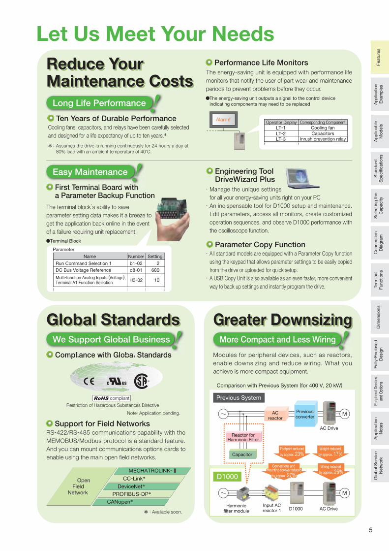
Let Us Meet Your NeedsReduce YourMaintenance Costs
Terminal Block
The energy-saving unit outputs a signal to the control device
indicating components may need to be replaced
Cooling fans, capacitors, and relays have been carefully selected
and designed for a life expectancy of up to ten years.*
Ten Years of Durable Performance
Compliance with Global Standards
RS-422/RS-485 communications capability with the
MEMOBUS/Modbus protocol is a standard feature.
And you can mount communications options cards to
enable using the main open field networks.
Support for Field Networks
* :
The terminal block’s ability to save
parameter setting data makes it a breeze to
get the application back online in the event
of a failure requiring unit replacement.
First Terminal Board with a Parameter Backup Function
Parameter Copy Function
Manage the unique settings
for all your energy-saving units right on your PC
An indispensable tool for D1000 setup and maintenance.
Edit parameters, access all monitors, create customized
operation sequences, and observe D1000 performance with
the oscilloscope function.
All standard models are equipped with a Parameter Copy function
using the keypad that allows parameter settings to be easily copied
from the drive or uploaded for quick setup.
A USB Copy Unit is also available as an even faster, more convenient
way to back up settings and instantly program the drive.
Engineering Tool DriveWizard Plus
* : Available soon.
MECHATROLINK-
CC-Link* Open FieldNetwork
DeviceNet*PROFIBUS-DP*
CANopen*
Restriction of Hazardous Substances Directive
compliant
Note: Application pending.
Name
Run Command Selection 1
DC Bus Voltage Reference
Multi-function Analog Inputs (Voltage), Terminal A1 Function Selection
Number Setting
2
680
10
b1-02
d8-01
H3-02
Parameter
Global StandardsGlobal Standards
Reduce YourMaintenance Costs
TeTT n YeYY ars of Durable Perfrr orma
Long Life Performance
First TeTT rminal Board with
Easy Maintenance
Compliance with Global Standards
We Support Global Business More Compact and Less Wiring
Greater DownsizingGreater Downsizing
Input ACreactor 1
Harmonicfilter module AC DriveD1000
Comparison with Previous System (for 400 V, 20 kW)
Previous System
D1000
ACreactor
Reactor forHarmonic Filter
Capacitor
AC Drive
Previousconverter
Footprint reduced
by approx. 23%
Wiring reduced
by approx. 25%
Weight reduced
by approx. 17%
The energy-saving unit is equipped with performance life
monitors that notify the user of part wear and maintenance
periods to prevent problems before they occur.
Performance Life Monitors
Alarm!!Operator Display Corresponding Component
LT-1 Cooling fan
LT-2 Capacitors
LT-3 Inrush prevention relay
Modules for peripheral devices, such as reactors,
enable downsizing and reduce wiring. What you
achieve is more compact equipment.
Assumes the drive is running continuously for 24 hours a day at
80% load with an ambient temperature of 40°C.
Connections and mounting screws reduced
by approx. 27%
Connections and mounting screws reduced
by approx. 27%
5
Ap
plic
ation
Exam
ple
sA
pp
licab
le
Mo
dels
Sta
nd
ard
S
pecifi c
atio
ns
Sele
cting
the
Cap
acity
Co
nnectio
n
Dia
gra
mTe
rmin
al
Functio
ns
Dim
ensio
ns
Fully
- Enclo
sed
D
esig
nP
erip
hera
l Dev
ices
an
d O
ptio
nsA
pp
licatio
n
No
tes
Glo
bal S
erv
ice
Netw
ork
Featu
res
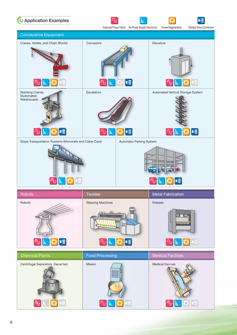
Application Examples
Conveyance Equipment
Chemical Plants Food Processing Medical Facilities
Robots Textiles Metal Fabrication
Cranes, Hoists, and Chain Blocks
Stacking Cranes (Automated Warehouses)
Slope Transportation Systems (Monorails and Cable Cars)
Conveyors
Escalators
Automatic Parking System
Elevators
Automated Vertical Storage System
Robots Weaving Machines Presses
Centrifugal Separators, Decanters Mixers Medical Devices
Improved Power Factor No Power Supply Harmonics Power Regeneration Multiple Drive Connection
rtical Storage
rs
anes
)
Devices
ion Systems (Monorails and Ca
l Separators, Decanters
6
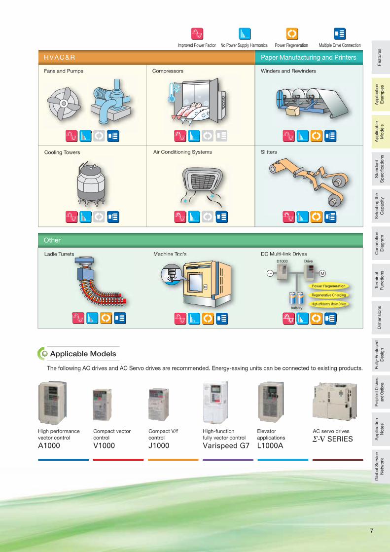
Applicable Models
High performance
vector control
A1000
Compact vector
control
V1000
Compact V/f
control
J1000
High-function
fully vector control
Varispeed G7
Elevator
applications
L1000A
HVAC&R
Other
Paper Manufacturing and Printers
Fans and Pumps
Air Conditioning Systems
Compressors
Cooling Towers
Ladle Turrets
The following AC drives and AC Servo drives are recommended. Energy-saving units can be connected to existing products.
Winders and Rewinders
Slitters
AC servo drives
SERIES
Improved Power Factor No Power Supply Harmonics Power Regeneration Multiple Drive Connection
Machine Tools DC Multi-link Drives
p
C Multi link Drives
Drive
batteryHigh-efficiency Motor Drives
Power Regeneration
Regenerative Charging
D1000
ts
~ M
Machine ToTT ols
7
Featu
res
Sta
nd
ard
S
pecifi c
atio
ns
Sele
cting
the
Cap
acity
Co
nnectio
n
Dia
gra
mTe
rmin
al
Functio
ns
Dim
ensio
ns
Fully
- Enclo
sed
D
esig
nP
erip
hera
l Dev
ices
an
d O
ptio
nsA
pp
licatio
n
No
tes
Glo
bal S
erv
ice
Netw
ork
Ap
plic
ation
Exam
ple
sA
pp
licab
le
Mo
dels
8
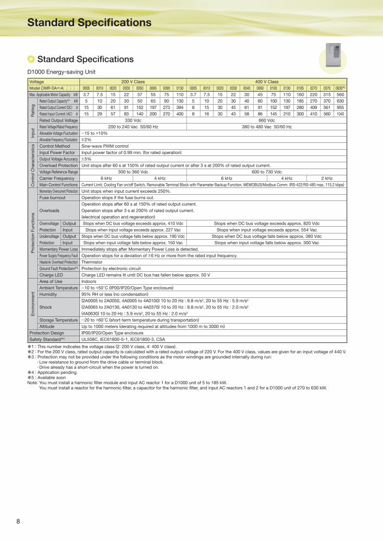
D1000 Energy-saving Unit
Standard Specifi cations
Standard Specifi cations
*1 : This number indicates the voltage class (2: 200 V class, 4: 400 V class).
*2 : For the 200 V class, rated output capacity is calculated with a rated output voltage of 220 V. For the 400 V class, values are given for an input voltage of 440 V.
*3 : Protection may not be provided under the following conditions as the motor windings are grounded internally during run:
Low resistance to ground from the drive cable or terminal block. Drive already has a short-circuit when the power is turned on.
*4 : Application pending.
*5 : Available soonNote: You must install a harmonic fi lter module and input AC reactor 1 for a D1000 unit of 5 to 185 kW.
You must install a reactor for the harmonic fi lter, a capacitor for the harmonic fi lter, and input AC reactors 1 and 2 for a D1000 unit of 270 to 630 kW.
Voltage 200 V Class 400 V Class
Model CIMR-DA A 0005 0010 0020 0030 0050 0065 0090 0130 0005 0010 0020 0030 0040 0060 0100 0130 0185 0270 0370 0630*5
Max. Applicable Motor Capacity kW 3.7 7.5 15 22 37 55 75 110 3.7 7.5 15 22 30 45 75 110 160 220 315 560
Rating
Rated Output Capacity*2 kW 5 10 20 30 50 65 90 130 5 10 20 30 40 60 100 130 185 270 370 630
Rated Output Current(DC) A 15 30 61 91 152 197 273 394 8 15 30 45 61 91 152 197 280 409 561 955
Rated Input Current(AC) A 15 29 57 83 140 200 270 400 8 16 30 43 58 86 145 210 300 410 560 1040
Rated Output Voltage 330 Vdc 660 Vdc
Inp
ut Rated Voltage/Rated Frequency 200 to 240 Vac 50/60 Hz 380 to 480 Vac 50/60 Hz
Allowable Voltage Fluctuation −15 to +10%
Allowable Frequency Fluctuation ±2%
Co
ntr
ol C
hara
cte
rist
ics Control Method Sine-wave PWM control
Input Power Factor Input power factor of 0.99 min. (for rated operation)
Output Voltage Accuracy ±5%
Overload Protection Unit stops after 60 s at 150% of rated output current or after 3 s at 200% of rated output current.
Voltage Reference Range 300 to 360 Vdc 600 to 730 Vdc
Carrier Frequency 6 kHz 4 kHz 6 kHz 4 kHz 2 kHz
Main Control Functions Current Limit, Cooling Fan on/off Switch, Removable Terminal Block with Parameter Backup Function, MEMOBUS/Modbus Comm. (RS-422/RS-485 max, 115.2 kbps)
Pro
tectio
n F
unctio
ns
Momentary Overcurrent Protection Unit stops when input current exceeds 250%.
Fuse burnout Operation stops if the fuse burns out.
Overloads
Operation stops after 60 s at 150% of rated output current.
Operation stops after 3 s at 200% of rated output current.
(electrical operation and regeneration)
Overvoltage
Protection
Output Stops when DC bus voltage exceeds approx. 410 Vdc Stops when DC bus voltage exceeds approx. 820 Vdc
Input Stops when input voltage exceeds approx. 227 Vac Stops when input voltage exceeds approx. 554 Vac
Undervoltage
Protection
Output Stops when DC bus voltage falls below approx. 190 Vdc Stops when DC bus voltage falls below approx. 380 Vdc
Input Stops when input voltage falls below approx. 150 Vac Stops when input voltage falls below approx. 300 Vac
Momentary Power Loss Immediately stops after Momentary Power Loss is detected.
Power Supply Frequency Fault Operation stops for a deviation of ±6 Hz or more from the rated input frequency.
Heatsink Overheat Protection Thermistor
Ground Fault Protectionn*3 Protection by electronic circuit
Charge LED Charge LED remains lit until DC bus has fallen below approx. 50 V
Enviro
nm
ent
Area of Use Indoors
Ambient Temperature −10 to +50°C (IP00/IP20/Open Type enclosure)
Humidity 95% RH or less (no condensation)
Shock
(2A0005 to 2A0050, 4A0005 to 4A0100) 10 to 20 Hz : 9.8 m/s2, 20 to 55 Hz : 5.9 m/s2
(2A0065 to 2A0130, 4A0130 to 4A0370) 10 to 20 Hz : 9.8 m/s2, 20 to 55 Hz : 2.0 m/s2
(4A0630) 10 to 20 Hz : 5.9 m/s2, 20 to 55 Hz : 2.0 m/s2
Storage Temperature −20 to +60°C (short-term temperature during transportation)
Altitude Up to 1000 meters (derating required at altitudes from 1000 m to 3000 m)
Protection Design IP00/IP20/Open Type enclosure
Safety Standard*4 UL508C, IEC61800-5-1, IEC61800-3, CSA
*1

9
Featu
res
Ap
plic
ation
Exam
ple
sA
pp
licab
le
Mo
dels
Sele
cting
the
Cap
acity
Co
nnectio
n
Dia
gra
mTe
rmin
al
Functio
ns
Dim
ensio
ns
Fully
- Enclo
sed
D
esig
nP
erip
hera
l Dev
ices
an
d O
ptio
nsA
pp
licatio
n
No
tes
Glo
bal S
erv
ice
Netw
ork
*1 : This number indicates the voltage class (2: 200 V class, 4: 400 V class).
*2 : Available soonNote: CIMR-DA 4A0630 requires two units of input AC reactor 1.
D1000 Standard Confi guration Devices
Model Number Key
CIMR- D A 2 A 0030 A A AYASKAWA Energy-Saving Unit D1000 Series Design Revision Order
No. Region Code
A Japan
No. Voltage Class
23-phase,
200-240 Vac
43-phase,
380-480 Vac
ModelRated Output
Capacity (kW)
0005 5
0010 10
0020 20
0030 30
0050 50
0065 65
0090 90
0130 130
ModelRated Output
Capacity (kW)
0005 5
0010 10
0020 20
0030 30
0040 40
0060 60
0100 100
0130 130
0185 185
0270 270
0370 370
0630 630
No. Customized Specifi cations
A Standard model
No. Enclosure Type
A IP00 open-chassis
B IP20 open-chassis
No. Environmental Specifi cations
A Standard
K Gas-resistant
M Humidity- and dust-resistant
N Oil-resistant
S Vibration-resistant
Three-Phase 200 V Three-Phase 400 V
Note: Contact a Yaskawa for more on environmental specifi cations.
Voltage 200 V 400 V
Model CIMR-DA A 0005 0010 0020 0030 0050 0065 0090 0130 0005 0010 0020 0030 0040 0060 0100 0130 0185 0270 0370 0630*2
Harmonic
Filter Module
Rated
CurrentA 15 29 57 83 140 200 270 400 8 16 30 43 58 86 145 210 300 - - -
Input AC
Reactor 1
Rated Current A 15 29 57 83 140 200 270 400 8 16 30 43 58 86 145 210 300 410 560 560
Inductance mH 2.45 1.27 0.64 0.44 0.26 0.18 0.14 0.09 9.19 4.59 2.45 1.71 1.27 0.85 0.51 0.35 0.25 0.18 0.13 0.13
Input AC
Reactor 2
Rated Current A- - - - - - - - - - - - - - - - -
410 560 1140
Inductance mH 0.06 0.05 0.02
Reactor for
Harmonic Filter
Rated Current A- - - - - - - - - - - - - - - - -
64 87 177
Inductance mH 0.022 0.0158 0.0079
Condenser for
Harmonic Filter
Rated
CapacityμF - - - - - - - - - - - - - - - - - 290 402 800
*1
Sta
nd
ard
S
pecifi c
atio
ns
10
Selecting the Capacity / Connection Diagram
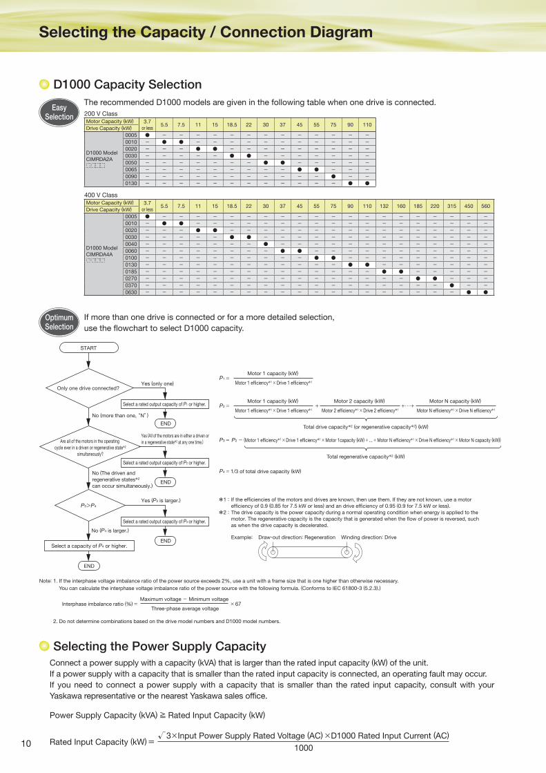
D1000 Capacity Selection
Selecting the Power Supply Capacity
If more than one drive is connected or for a more detailed selection,
use the flowchart to select D1000 capacity.
Connect a power supply with a capacity (kVA) that is larger than the rated input capacity (kW) of the unit.
If a power supply with a capacity that is smaller than the rated input capacity is connected, an operating fault may occur.
If you need to connect a power supply with a capacity that is smaller than the rated input capacity, consult with your
Yaskawa representative or the nearest Yaskawa sales office.
Power Supply Capacity (kVA) ≧ Rated Input Capacity (kW)
P1 =Motor 1 capacity (kW)
Motor 1 efficiency*1 × Drive 1 efficiency*1
P2 = + +・・・+Motor 1 capacity (kW)
Motor 1 efficiency*1 × Drive 1 efficiency*1
Motor 2 capacity (kW)
Motor 2 efficiency*1 × Drive 2 efficiency*1
Motor N capacity (kW)
Motor N efficiency*1 × Drive N efficiency*1
P3 = P2 - (Motor 1 efficiency*1 × Drive 1 efficiency*1 × Motor 1capacity (kW) + ... + Motor N efficiency*1 × Drive N efficiency*1 × Motor N capacity (kW))
P4 = 1/3 of total drive capacity (kW)
Only one drive connected?
START
Select a capacity of P4 or higher.
Are all of the motors in the operating
cycle ever in a driven or regenerative state*2
simultaneously?
P3>P4
Select a rated output capacity of P1 or higher.
END
Yes (only one)
Yes (All of the motors are in either a driven or
in a regenerative state*2 at any one time.)
Yes (P3 is larger.)
No (more than one, “N”)
No (The driven and
regenerative states*2
can occur simultaneously.)
No (P4 is larger.)
Total drive capacity*2 (or regenerative capacity*2) (kW)
Total regenerative capacity*2 (kW)
END
Select a rated output capacity of P2 or higher.
END
Select a rated output capacity of P3 or higher.
END
If the efficiencies of the motors and drives are known, then use them. If they are not known, use a motor
efficiency of 0.9 (0.85 for 7.5 kW or less) and an drive efficiency of 0.95 (0.9 for 7.5 kW or less).
The drive capacity is the power capacity during a normal operating condition when energy is applied to the
motor. The regenerative capacity is the capacity that is generated when the flow of power is reversed, such
as when the drive capacity is decelerated.
*1 :
*2 :
Example: Draw-out direction: Regeneration Winding direction: Drive
Interphase imbalance ratio (%) = × 67Maximum voltage - Minimum voltage
Three-phase average voltage
Motor Capacity (kW) 3.7
or less5.5 7.5 11 15 18.5 22 30 37 45 55 75 90 110
Drive Capacity (kW)
D1000 Model
CIMRDA2A
0005 ● - - - - - - - - - - - - -0010 - ● ● - - - - - - - - - - -0020 - - - ● ● - - - - - - - - -0030 - - - - - ● ● - - - - - - -0050 - - - - - - - ● ● - - - - -0065 - - - - - - - - - ● ● - - -0090 - - - - - - - - - - - ● - -0130 - - - - - - - - - - - - ● ●
The recommended D1000 models are given in the following table when one drive is connected.
Note: 1. If the interphase voltage imbalance ratio of the power source exceeds 2%, use a unit with a frame size that is one higher than otherwise necessary.
You can calculate the interphase voltage imbalance ratio of the power source with the following formula. (Conforms to IEC 61800-3 (5.2.3).)
2. Do not determine combinations based on the drive model numbers and D1000 model numbers.
200 V Class
400 V Class
EasySelection
OptimumSelection
Motor Capacity (kW) 3.7
or less5.5 7.5 11 15 18.5 22 30 37 45 55 75 90 110 132 160 185 220 315 450 560
Drive Capacity (kW)
D1000 Model
CIMRDA4A
0005 ● - - - - - - - - - - - - - - - - - - - -0010 - ● ● - - - - - - - - - - - - - - - - - -0020 - - - ● ● - - - - - - - - - - - - - - - -0030 - - - - - ● ● - - - - - - - - - - - - - -0040 - - - - - - - ● - - - - - - - - - - - - -0060 - - - - - - - - ● ● - - - - - - - - - - -0100 - - - - - - - - - - ● ● - - - - - - - - -0130 - - - - - - - - - - - - ● ● - - - - - - -0185 - - - - - - - - - - - - - - ● ● - - - - -0270 - - - - - - - - - - - - - - - - ● ● - - -0370 - - - - - - - - - - - - - - - - - - ● - -0630 - - - - - - - - - - - - - - - - - - - ● ●
Rated Input Capacity (kW)=√3× Input Power Supply Rated Voltage (AC) ×D1000 Rated Input Current (AC)
1000
11
Featu
res
Ap
plic
ation
Exam
ple
sA
pp
licab
le
Mo
dels
Sta
nd
ard
S
pecifi c
atio
ns
Term
inal
Functio
ns
Dim
ensio
ns
Fully
- Enclo
sed
D
esig
nP
erip
hera
l Dev
ices
an
d O
ptio
nsA
pp
licatio
n
No
tes
Glo
bal S
erv
ice
Netw
ork
Co
nnectio
n
Dia
gra
mS
ele
cting
the
Cap
acity
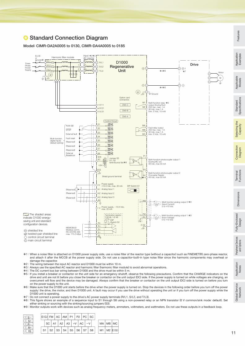
Model: CIMR-DA2A0005 to 0130, CIMR-DA4A0005 to 0185
Standard Connection Diagram
M
S1
S2
S3
S4
S5
S6
S7
S8
SC
E(G)
MA
MB
MC
RUN-SB
External fault
Fault reset
(Reserved)
(Reserved)
(Reserved)
ExternalBaseblock
Shield ground terminal
STOP
PC
V I
MEMOBUS/Modbus comm.RS-422/RS-485max. 115.2 kBps
P2
P1
M1
M2
1
D1000Regenerative
Unit
Drive
Motor
Multi-functiondigital inputs(default setting)
Fault relay output250 Vac, max. 1 A30 Vdc, max 1 A(min. 5 Vdc, 10 mA)
+V
A1
A2
A3
AC
(Reserved)
(Reserved)
(Reserved)
+24 V
Control Circuit
-V
Analog Input 1
Analog Input 2
Analog Input 3
DIP Switch S1
Termination resistor(120 Ω, 1/2 W)
DIPSwitch S2
Multi-function photocoupler output 1(During MC on)48 Vdc, max 50 mA
Multi-function photocoupler output 2(Converter Ready)48 Vdc, max 50 mA
Multi-function relayoutput (During Run)250 Vac, max. 1 A30 Vdc, max 1 A(min. 5 Vdc, 10 mA)
AM
AC
0V
E (G)R+R-
S+S-
IG
FM
Multi-function analog output 2(Input Current)0 to +10 Vdc
Multi-function analog output 1(Input Voltage)0 to +10 Vdc
Three-PhasePowerSupply
Input AC reactorHarmonic filter module
U
V
W
X
Y
Z
R/L1
S/L2
T/L3
ELCBorMCCB X
Y
Z
R/L1
S/L2
T/L3
r t
CN5-A
CN5-B
CN5-C
Option cardconnectors
Ground
SinkJumper S3H1, H2Sink/Source Sel.
Power supply+10.5 Vdc, max. 20 mA
FM
AM
Power supply, -10.5 Vdc,max. 20 mA
*7
*4*5
*6
*2*3
*1
*4*5
*8
*9
*9
r1/ 11
1/ 21
t1/ 31
+ +
- -
+-
+-
*1 : When a noise fi lter is attached on D1000 power supply side, use a noise fi lter of the reactor type (without a capacitor) such as FINEMET(R) zero-phase reactor, and attach it after the MCCB at the power supply side. Do not use a capacitor-built-in type noise fi lter since the harmonic components may overheat or damage the capacitor.
*2 : The wiring between the input AC reactor and D1000 must be within 10 m.
*3 : Always use the specifi ed AC reactor and harmonic fi lter (harmonic fi lter module) to avoid abnormal operations.
*4 : The DC current bus bar wiring between D1000 and the drive must be within 5 m.
*5 : If you install a breaker or contactor on the unit side for an emergency shutoff, observe the following precautions. Confi rm that the CHARGE indicators on the drive and unit are not lit before you close the breaker or contactor on the unit output (DC) side. If the power supply is turned on while voltages are charging, an overcurrent will fl ow and the device may be damaged. Always confi rm that the breaker or contactor on the unit output (DC) side is turned on before you turn on the power supply to the unit.
*6 : Make sure that the D1000 unit starts before the drive when the power supply is turned on. Stop the devices in the following order before you turn off the power supply: the drive, the motor, and then D1000 unit. A fault may occur if you use the drive without operating the unit or if you turn off the power supply while the D1000 unit is operating.
*7 : Do not connect a power supply to the drive’s AC power supply terminals (R/L1, S/L2, and T/L3).
*8 : This fi gure shows an example of a sequence input to S1 through S8 using a non-powered relay or an NPN transistor (0 V common/sink mode: default). Set either sinking or sourcing with the sinking/sourcing jumpers (S3).
*9 : Monitor outputs work with devices such as analog frequency meters, ammeters, voltmeters, and wattmeters. Do not use these outputs in a feedback loop.
The shaded areas indicate D1000 energy-
saving unit and standard confi guration devices.
E(G)FM AC AM P1 P2 PC SC
S2S1 S3 S4 S5 S6 S7 S8
SC A1 A2 A3 +V AC -V
M1 M2 E(G)
MA MB MC
IG
R+R-S+S-
shielded linetwisted-pair shielded linecontrol circuit terminalmain circuit terminal
12
Connection Diagram (continued)
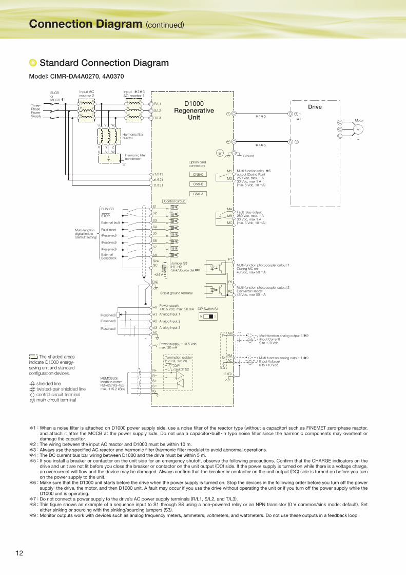
Standard Connection Diagram
Model: CIMR-DA4A0270, 4A0370
*1 : When a noise fi lter is attached on D1000 power supply side, use a noise fi lter of the reactor type (without a capacitor) such as FINEMET zero-phase reactor, and attach it after the MCCB at the power supply side. Do not use a capacitor-built-in type noise fi lter since the harmonic components may overheat or damage the capacitor.
*2 : The wiring between the input AC reactor and D1000 must be within 10 m.
*3 : Always use the specifi ed AC reactor and harmonic fi lter (harmonic fi lter module) to avoid abnormal operations.
*4 : The DC current bus bar wiring between D1000 and the drive must be within 5 m.
*5 : If you install a breaker or contactor on the unit side for an emergency shutoff, observe the following precautions. Confi rm that the CHARGE indicators on the drive and unit are not lit before you close the breaker or contactor on the unit output (DC) side. If the power supply is turned on while there is a voltage charge, an overcurrent will fl ow and the device may be damaged. Always confi rm that the breaker or contactor on the unit output (DC) side is turned on before you turn on the power supply to the unit.
*6 : Make sure that the D1000 unit starts before the drive when the power supply is turned on. Stop the devices in the following order before you turn off the power supply: the drive, the motor, and then D1000 unit. A fault may occur if you use the drive without operating the unit or if you turn off the power supply while the D1000 unit is operating.
*7 : Do not connect a power supply to the drive’s AC power supply terminals (R/L1, S/L2, and T/L3).
*8 : This fi gure shows an example of a sequence input to S1 through S8 using a non-powered relay or an NPN transistor (0 V common/sink mode: default). Set either sinking or sourcing with the sinking/sourcing jumpers (S3).
*9 : Monitor outputs work with devices such as analog frequency meters, ammeters, voltmeters, and wattmeters. Do not use these outputs in a feedback loop.
M
S1
S2
S3
S4
S5
S6
S7
S8
E(G)
MA
MB
MC
M1
M2
1
Motor
+V
A1
A2
A3
AC
+24 V
-V
R/L1
S/L2
T/L3
CN5-A
CN5-B
CN5-C
Option cardconnectors
U
V
W
X
Y
Z
U
V
W
X
Y
Z
Harmonic filterreactor
U V W
X Y Z
U V W
EHarmonic filtercondencer
Drive
V I
R+R-
S+S-
IG
Input ACreactor 2
Input AC reactor 1
ELCBorMCCB
Ground
AM
AC
0V
E (G)
FM
FM
AM
Shield ground terminal
*7
*2*3
*1
*4*5
*4*5
r1/ 11
1/ 21
t1/ 31
+ +
- -
+-
+-
D1000Regenerative
Unit
PC
P2
P1
Three-PhasePowerSupply
RUN-SB
External fault
Fault reset
(Reserved)
(Reserved)
(Reserved)
ExternalBaseblock
STOP
Multi-functiondigital inputs(default setting)
Control Circuit
SC
SinkJumper S3H1, H2Sink/Source Sel.*8
(Reserved)
(Reserved)
(Reserved) Analog Input 1
Analog Input 2
Analog Input 3
Power supply+10.5 Vdc, max. 20 mA DIP Switch S1
Power supply, -10.5 Vdc,max. 20 mA
Termination resistor(120 Ω, 1/2 W)
DIPSwitch S2
MEMOBUS/Modbus comm.RS-422/RS-485max. 115.2 kBps
Multi-function analog output 2(Input Current)0 to +10 Vdc
Multi-function analog output 1(Input Voltage)0 to +10 Vdc
Multi-function photocoupler output 1(During MC on)48 Vdc, max 50 mA
Multi-function photocoupler output 2(Converter Ready)48 Vdc, max 50 mA
Fault relay output250 Vac, max. 1 A30 Vdc, max 1 A(min. 5 Vdc, 10 mA)
Multi-function relayoutput (During Run)250 Vac, max. 1 A30 Vdc, max 1 A(min. 5 Vdc, 10 mA)
*6
*9
*9 The shaded areas indicate D1000 energy-
saving unit and standard confi guration devices.
shielded linetwisted-pair shielded linecontrol circuit terminalmain circuit terminal

13
Feat
ures
App
licat
ion
Exa
mpl
esA
pp
licab
le
Mod
els
Sta
ndar
d
Sp
ecifi
catio
nsS
elec
ting
the
Cap
acity
Term
inal
Fu
nctio
nsD
imen
sion
sFu
lly- E
nclo
sed
D
esig
nPe
riphe
ral D
evic
es
and
Opt
ions
Ap
plic
atio
n N
otes
Glo
bal
Ser
vice
N
etw
ork
Con
nect
ion
Dia
gram
Model: CIMR-DA4A0630 (Available soon)
*1: When a noise filter is attached on D1000 power supply side, use a noise filter of the reactor type (without a capacitor) such as FINEMET zero-phase reactor, and attach it after the MCCB at the power supply side. Do not use a capacitor-built-in type noise filter since the harmonic components may overheat or damage the capacitor.
*2: The wiring between the input AC reactor and D1000 must be within 10 m.
*3: Always use the specified AC reactor and harmonic filter (harmonic filter module) to avoid abnormal operations.
*4: The DC current bus bar wiring between D1000 and the drive must be within 5 m.
*5: If you install a breaker or contactor on the unit side for an emergency shutoff, observe the following precautions. Confirm that the CHARGE indicators on the drive and unit are not lit before you close the breaker or contactor on the unit output (DC) side. If the power supply is turned on while there is a voltage charge, an overcurrent will flow and the device may be damaged. Always confirm that the breaker or contactor on the unit output (DC) side is turned on before you turn on the power supply to the unit.
*6: Make sure that the D1000 unit starts before the drive when the power supply is turned on. Stop the devices in the following order before you turn off the power supply: the drive, the motor, and then D1000 unit. A fault may occur if you use the drive without operating the unit or if you turn off the power supply while the D1000 unit is operating.
*7: Do not connect a power supply to the drive’s AC power supply terminals (R/L1, S/L2, and T/L3).
*8: This figure shows an example of a sequence input to S1 through S8 using a non-powered relay or an NPN transistor (0 V common/sink mode: default). Set either sinking or sourcing with the sinking/sourcing jumpers (S3).
*9: Monitor outputs work with devices such as analog frequency meters, ammeters, voltmeters, and wattmeters. Do not use these outputs in a feedback loop.
IM
S1
S2
S3
S4
S5
S6
S7
S8
SC
E(G)
MA
MB
MC
M1
M2
Drive
Motor
Fault relay output250 Vac, max. 1 A30 Vdc, max 1 A(min. 5 Vdc, 10 mA)
Multi-function relayoutput (During Run)250 Vac, max. 1 A30 Vdc, max 1 A(min. 5 Vdc, 10 mA)
R/L1
S/L2
T/L3
Option cardconnectors
U
V
W
X
Y
Z
U
V
W
X
Y
Z
X Y Z
Ground
Sink
E
Input ACreactor 1U
V
W
X
Y
Z
R1/L11
S1/L21
T1/L31
V
DIP Switch S1
AM
AC +
0 V
E (G)
FM
FM
+
-
-AM
PC
P2
P1
Input ACreactor 2
Input ACreactor 1
U V W
U V W
*2*3
Harmonic �lterreactor *3
Harmonic �ltercondencer
r1/ 11
1/ 21
t1/ 31
+
-
CN5-A
CN5-B
CN5-C
+24 V
+V
A1
A2
A3AC
I
-V
R+R-
S+S-
IG
*6
*4*5
*4*51
*7
+
-
Three-PhasePowerSupply
ELCBorMCCB*1
D1000Regenerative
Unit
RUN-SB
External fault
Fault reset
(Reserved)
(Reserved)
(Reserved)
ExternalBaseblock
STOP
Multi-functiondigital inputs(default setting)
Control Circuit
Jumper S3H1, H2Sink/Source Sel.*8
Shield ground terminal
Analog Input 1
Analog Input 2
Analog Input 3
Power supply+10.5 Vdc, max. 20 mA
Termination resistor(120 Ω, 1/2 W)
DIPSwitch S2
Power supply, -10.5 Vdc,max. 20 mA
MEMOBUS/Modbus comm.RS-422/RS-485max. 115.2 kBps
Multi-function photocoupler output 1(During MC on)48 Vdc, max 50 mA
Multi-function photocoupler output 2(Converter Ready)48 Vdc, max 50 mA
Multi-function analog output 2(Input Current)0 to +10 Vdc
Multi-function analog output 1(Input Voltage)0 to +10 Vdc
*9
*9
(Reserved)
(Reserved)
(Reserved)
The shaded areas indicate D1000 energy-saving unit and standard con�guration devices.
shielded linetwisted-pair shielded linecontrol circuit terminalmain circuit terminal
14
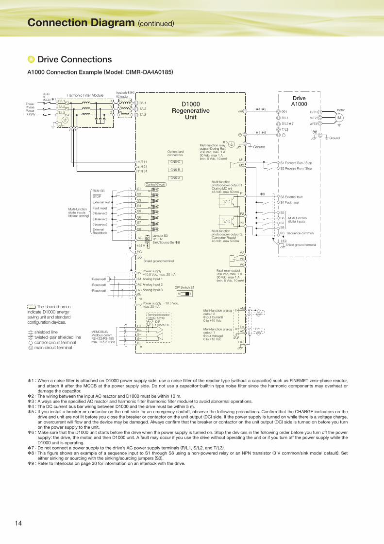
Drive Connections
A1000 Connection Example (Model: CIMR-DA4A0185)
*1 : When a noise fi lter is attached on D1000 power supply side, use a noise fi lter of the reactor type (without a capacitor) such as FINEMET zero-phase reactor, and attach it after the MCCB at the power supply side. Do not use a capacitor-built-in type noise fi lter since the harmonic components may overheat or damage the capacitor.
*2 : The wiring between the input AC reactor and D1000 must be within 10 m.
*3 : Always use the specifi ed AC reactor and harmonic fi lter (harmonic fi lter module) to avoid abnormal operations.
*4 : The DC current bus bar wiring between D1000 and the drive must be within 5 m.
*5 : If you install a breaker or contactor on the unit side for an emergency shutoff, observe the following precautions. Confi rm that the CHARGE indicators on the drive and unit are not lit before you close the breaker or contactor on the unit output (DC) side. If the power supply is turned on while there is a voltage charge, an overcurrent will fl ow and the device may be damaged. Always confi rm that the breaker or contactor on the unit output (DC) side is turned on before you turn on the power supply to the unit.
*6 : Make sure that the D1000 unit starts before the drive when the power supply is turned on. Stop the devices in the following order before you turn off the power supply: the drive, the motor, and then D1000 unit. A fault may occur if you use the drive without operating the unit or if you turn off the power supply while the D1000 unit is operating.
*7 : Do not connect a power supply to the drive’s AC power supply terminals (R/L1, S/L2, and T/L3).
*8 : This fi gure shows an example of a sequence input to S1 through S8 using a non-powered relay or an NPN transistor (0 V common/sink mode: default). Set either sinking or sourcing with the sinking/sourcing jumpers (S3).
*9 : Refer to Interlocks on page 30 for information on an interlock with the drive.
S1
S2
S3
S4
S5
S6
S7
S8
SC
E(G) MA
MB
MC
RUN-SB
External fault
Fault reset
(Reserved)
(Reserved)
(Reserved)
ExternalBaseblock
Shield ground terminal
Jumper S3H1, H2Sink/Source Sel
STOP
D1000Regenerative
Unit
Multi-functiondigital inputs(default setting)
Fault relay output250 Vac, max. 1 A30 Vdc, max 1 A(min. 5 Vdc, 10 mA)
+V
A1
A2
A3AC
R+R-S+S-IG
V I
MEMOBUS/Modbus comm.RS-422/RS-485max. 115.2 kBps
Control Circuit
-V
Power supply+10.5 Vdc, max. 20 mA
Analog Input 1
Analog Input 2
Analog Input 3DIP Switch S1
Multi-functionphotocoupler output 1(During MC on)48 Vdc, max 50 mA
Multi-functionphotocoupler output 2(Converter Ready)48 Vdc, max 50 mA
Multi-function relayoutput (During Run)250 Vac, max. 1 A30 Vdc, max 1 A(min. 5 Vdc, 10 mA)
Multi-function analogoutput 1(Input Voltage)0 to +10 Vdc
Multi-function analogoutput 2(Input Current)0 to +10 Vdc
Input side AC reactorHarmonic Filter Module
U
V
W
X
Y
Z
R/L1
S/L2
T/L3
ELCBorMCCB X
Y
Z
R/L1
S/L2
T/L3
r t
CN5-A
CN5-B
CN5-C
Option cardconnectors
S1 Forward Run / Stop
S2 Reverse Run / Stop
S3 External fault
S4 Fault reset
S5
S6
S7
S8
SC Sequence common
Multi-functiondigital inputs
Shield ground terminalE(G)
DriveA1000
R/L1
1
S/L2
T/L3
IM
U/T1
V/T2
W/T3
Ground
Motor
AC
E(G)
FM
AM
Ground
*1
*2*3
*4 *5
*4 *5
*7
*6
*9
*8
+ +
- -
M1
M2
AM
FM+-
+-
0 V
+24 V
r1/ 11
1/ 21
t1/ 31
PC
P2
P1
Three-PhasePowerSupply
Power supply, -10.5 Vdc,max. 20 mA
Termination resistor(120 Ω, 1/2 W)
DIPSwitch S2
(Reserved)
(Reserved)
(Reserved)
Connection Diagram (continued)
The shaded areas indicate D1000 energy-
saving unit and standard confi guration devices.
shielded linetwisted-pair shielded linecontrol circuit terminalmain circuit terminal
15
Featu
res
Ap
plic
ation
Exam
ple
sA
pp
licab
le
Mo
dels
Sta
nd
ard
S
pecifi c
atio
ns
Sele
cting
the
Cap
acity
Term
inal
Functio
ns
Dim
ensio
ns
Fully
- Enclo
sed
D
esig
nP
erip
hera
l Dev
ices
an
d O
ptio
nsA
pp
licatio
n
No
tes
Glo
bal S
erv
ice
Netw
ork
Co
nnectio
n
Dia
gra
m
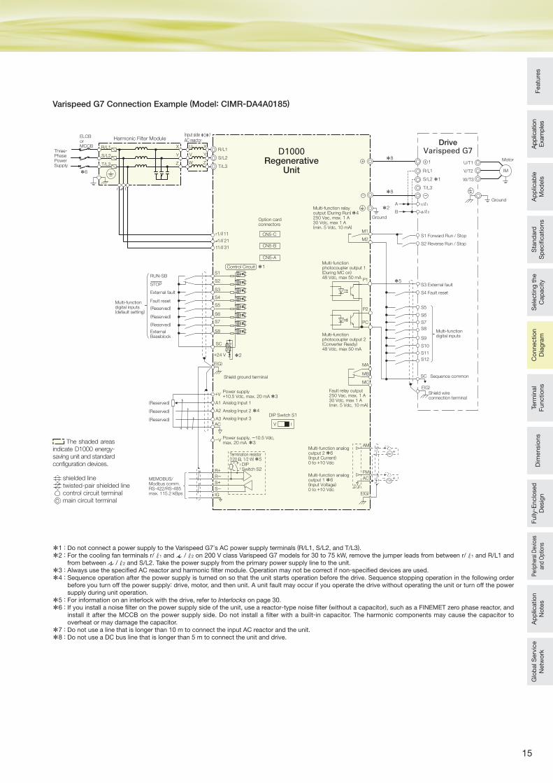
Varispeed G7 Connection Example (Model: CIMR-DA4A0185)
*1 : Do not connect a power supply to the Varispeed G7’s AC power supply terminals (R/L1, S/L2, and T/L3).
*2 : For the cooling fan terminals r/ 1 and / 2 on 200 V class Varispeed G7 models for 30 to 75 kW, remove the jumper leads from between r/ 1 and R/L1 and from between / 2 and S/L2. Take the power supply from the primary power supply line to the unit.
*3 : Always use the specifi ed AC reactor and harmonic fi lter module. Operation may not be correct if non-specifi ed devices are used.
*4 : Sequence operation after the power supply is turned on so that the unit starts operation before the drive. Sequence stopping operation in the following order before you turn off the power supply: drive, motor, and then unit. A unit fault may occur if you operate the drive without operating the unit or turn off the power supply during unit operation.
*5 : For information on an interlock with the drive, refer to Interlocks on page 30.
*6 : If you install a noise fi lter on the power supply side of the unit, use a reactor-type noise fi lter (without a capacitor), such as a FINEMET zero phase reactor, and install it after the MCCB on the power supply side. Do not install a fi lter with a built-in capacitor. The harmonic components may cause the capacitor to overheat or may damage the capacitor.
*7 : Do not use a line that is longer than 10 m to connect the input AC reactor and the unit.
*8 : Do not use a DC bus line that is longer than 5 m to connect the unit and drive.
Ground
S1
S2
S3
S4
S5
S6
S7
S8
SC
E(G) MA
MB
MCShield ground terminal
M1
A
B
M2
Fault relay output250 Vac, max. 1 A30 Vdc, max 1 A(min. 5 Vdc, 10 mA)
+V
A1
A2
A3AC
R+R-S+S-IG
V I
+24 V
-V
DIP Switch S1
Multi-functionphotocoupler output 1(During MC on)48 Vdc, max 50 mA
Multi-functionphotocoupler output 2(Converter Ready)48 Vdc, max 50 mA
Multi-function relayoutput (During Run)250 Vac, max. 1 A30 Vdc, max 1 A(min. 5 Vdc, 10 mA)
AM
Multi-function analogoutput 1(Input Voltage)0 to +10 Vdc
Multi-function analogoutput 2(Input Current)0 to +10 Vdc
Input side AC reactorHarmonic Filter Module
U
V
W
X
Y
Z
R/L1
S/L2
T/L3
ELCBorMCCB X
Y
Z
R/L1
S/L2
T/L3
CN5-A
CN5-B
CN5-C
Option cardconnectors
S1 Forward Run / Stop
S2 Reverse Run / Stop
S3 External fault
S4 Fault reset
S5
S6
S7
S8
SC Sequence common
Multi-functiondigital inputs
Shield wireconnection terminal
E(G)
DriveVarispeed G7+
R/L1
1
S/L2
T/L3
-
+
-
IM
U/T1
V/T2
W/T3
Ground
Motor
0 V
AC
E(G)
FM
AM
FM+-
+-*6
*4
*3
*5
*3
*2
*1
*6
S9
S10
S11
S12
r1/ 11
1/ 21
t1/ 31
r t
r/ 1
/ 2
*1
*2
*8
*5
*8
*6
*3*7
*4
PC
P2
P1
Three-PhasePowerSupply
D1000Regenerative
Unit
RUN-SB
External fault
Fault reset
(Reserved)
(Reserved)
(Reserved)
ExternalBaseblock
STOP
Multi-functiondigital inputs(default setting)
Control Circuit
(Reserved)
(Reserved)
(Reserved)
Power supply+10.5 Vdc, max. 20 mA
Analog Input 1
Analog Input 2
Analog Input 3
Power supply, -10.5 Vdc,max. 20 mA
MEMOBUS/Modbus comm.RS-422/RS-485max. 115.2 kBps
Termination resistor(120 Ω, 1/2 W)
DIPSwitch S2
The shaded areas indicate D1000 energy-
saving unit and standard confi guration devices.
shielded linetwisted-pair shielded linecontrol circuit terminalmain circuit terminal
16
Terminal Functions
Terminal Functions
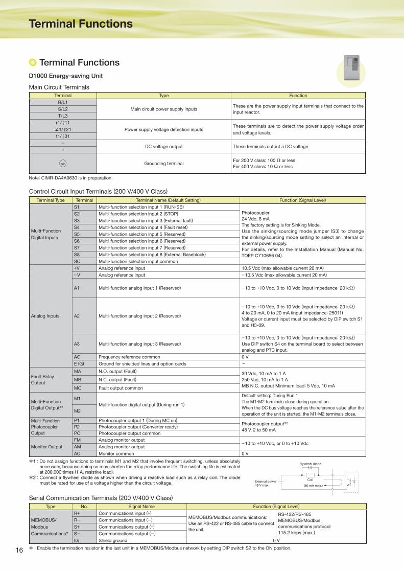
Main Circuit Terminals
D1000 Energy-saving Unit
Control Circuit Input Terminals (200 V/400 V Class)
Serial Communication Terminals (200 V/400 V Class)
Terminal Type Terminal Terminal Name (Default Setting) Function (Signal Level)
Multi-Function
Digital Inputs
S1 Multi-function selection input 1 (RUN-SB)
Photocoupler
24 Vdc, 8 mA
The factory setting is for Sinking Mode.
Use the sinking/sourcing mode jumper (S3) to change
the sinking/sourcing mode setting to select an internal or
external power supply.
For details, refer to the Installation Manual (Manual No.
TOEP C710656 04).
S2 Multi-function selection input 2 (STOP)
S3 Multi-function selection input 3 (External fault)
S4 Multi-function selection input 4 (Fault reset)
S5 Multi-function selection input 5 (Reserved)
S6 Multi-function selection input 6 (Reserved)
S7 Multi-function selection input 7 (Reserved)
S8 Multi-function selection input 8 (External Baseblock)
SC Multi-function selection input common
Analog Inputs
+V Analog reference input 10.5 Vdc (max allowable current 20 mA)
−V Analog reference input −10.5 Vdc (max allowable current 20 mA)
A1 Multi-function analog input 1 (Reserved) −10 to +10 Vdc, 0 to 10 Vdc (input impedance: 20 kΩ )
A2 Multi-function analog input 2 (Reserved)
−10 to +10 Vdc, 0 to 10 Vdc (input impedance: 20 kΩ )
4 to 20 mA, 0 to 20 mA (input impedance: 250Ω )
Voltage or current input must be selected by DIP switch S1
and H3-09.
A3 Multi-function analog input 3 (Reserved)
−10 to +10 Vdc, 0 to 10 Vdc (input impedance: 20 kΩ )
Use DIP switch S4 on the terminal board to select between
analog and PTC input.
AC Frequency reference common 0 V
E (G) Ground for shielded lines and option cards -
Fault Relay
Output
MA N.O. output (Fault) 30 Vdc, 10 mA to 1 A
250 Vac, 10 mA to 1 A
MB N.C. output Minimum load: 5 Vdc, 10 mA
MB N.C. output (Fault)
MC Fault output common
Multi-Function
Digital Output*1
M1
Multi-function digital output (During run 1)
Default setting: During Run 1
The M1-M2 terminals close during operation.
When the DC bus voltage reaches the reference value after the
operation of the unit is started, the M1-M2 terminals close.M2
Multi-Function
Photocoupler
Output
P1 Photocoupler output 1 (During MC on)Photocoupler output*2
48 V, 2 to 50 mAP2 Photocoupler output (Converter ready)
PC Photocoupler output common
Monitor Output
FM Analog monitor output −10 to +10 Vdc, or 0 to +10 VdcAM Analog monitor output
AC Monitor common 0 V
*1 : Do not assign functions to terminals M1 and M2 that involve frequent switching, unless absolutely necessary, because doing so may shorten the relay performance life. The switching life is estimated at 200,000 times (1 A, resistive load).
*2 : Connect a fl ywheel diode as shown when driving a reactive load such as a relay coil. The diode must be rated for use of a voltage higher than the circuit voltage.
Note: CIMR-DA4A0630 is in preparation.
* : Enable the termination resistor in the last unit in a MEMOBUS/Modbus network by setting DIP switch S2 to the ON position.
Terminal Type Function
R/L1
Main circuit power supply inputsThese are the power supply input terminals that connect to the
input reactor.S/L2
T/L3
r1/ 11
Power supply voltage detection inputsThese terminals are to detect the power supply voltage order
and voltage levels.1/ 21
t1/ 31
−DC voltage output These terminals output a DC voltage+
Grounding terminalFor 200 V class: 100 Ω or less
For 400 V class: 10 Ω or less
(50 mA max.)
CoilExternal power 48 V max.
Flywheel diode
Type No. Signal Name Function (Signal Level)
MEMOBUS/
Modbus
Communications*
R+ Communications input (+)MEMOBUS/Modbus communications:
Use an RS-422 or RS-485 cable to connect
the unit.
RS-422/RS-485
MEMOBUS/Modbus
communications protocol
115.2 kbps (max.)
R− Communications input (− )
S+ Communications output (+)
S− Communications output (− )
IG Shield ground 0 V
17
Featu
res
Ap
plic
ation
Exam
ple
sA
pp
licab
le
Mo
dels
Sta
nd
ard
S
pecifi c
atio
ns
Sele
cting
the
Cap
acity
Co
nnectio
n
Dia
gra
mD
imensio
ns
Fully
- Enclo
sed
D
esig
nP
erip
hera
l Dev
ices
an
d O
ptio
nsA
pp
licatio
n
No
tes
Glo
bal S
erv
ice
Netw
ork
Term
inal
Functio
ns
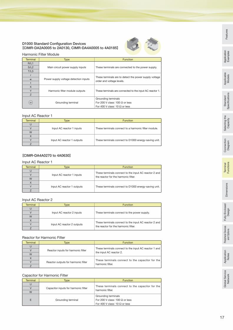
Harmonic Filter Module
【CIMR-DA2A0005 to 2A0130, CIMR-DA4A0005 to 4A0185】
【CIMR-DA4A0270 to 4A0630】
Input AC Reactor 1
Input AC Reactor 2
Input AC Reactor 1
Reactor for Harmonic Filter
Capacitor for Harmonic Filter
Terminal Type Function
R/L1
Main circuit power supply inputs These terminals are connected to the power supply.S/L2
T/L3
r
Power supply voltage detection inputsThese terminals are to detect the power supply voltage
order and voltage levels.t
X
Harmonic fi lter module outputs These terminals are connected to the input AC reactor 1.Y
Z
Grounding terminal
Grounding terminals
For 200 V class: 100 Ω or less
For 400 V class: 10 Ω or less
Terminal Type Function
U
Input AC reactor 1 inputs These terminals connect to a harmonic fi lter module.V
W
X
Input AC reactor 1 outputs These terminals connect to D1000 energy-saving unit.Y
Z
Terminal Type Function
U
Input AC reactor 2 inputs These terminals connect to the power supply.V
W
X
Input AC reactor 2 outputsThese terminals connect to the input AC reactor 2 and
the reactor for the harmonic fi lter.Y
Z
Terminal Type Function
U
Input AC reactor 1 inputsThese terminals connect to the input AC reactor 2 and
the reactor for the harmonic fi lter.V
W
X
Input AC reactor 1 outputs These terminals connect to D1000 energy-saving unit.Y
Z
Terminal Type Function
U
Reactor inputs for harmonic fi lterThese terminals connect to the input AC reactor 1 and
the input AC reactor 2.V
W
X
Reactor outputs for harmonic fi lterThese terminals connect to the capacitor for the
harmonic fi lter.Y
Z
Terminal Type Function
U
Capacitor inputs for harmonic fi lterThese terminals connect to the capacitor for the
harmonic fi lter.V
W
E Grounding terminal
Grounding terminals
For 200 V class: 100 Ω or less
For 400 V class: 10 Ω or less
D1000 Standard Confi guration Devices
18
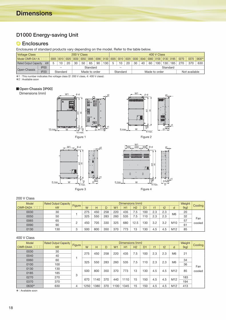
Enclosures
Dimensions
Open-Chassis【IP00】
D1000 Energy-saving Unit
Model
CIMR-DA2A
Rated Output Capacity
kWFigure
Dimensions (mm) Weight
(kg)Cooling
W H D W1 H1 H2 D1 t1 t2 d
0030 301
275 450 258 220 435 7.5 100 2.3 2.3M6
20
Fan
cooled
0050 50 325 550 283 260 535 7.5 110 2.3 2.3 32
0065 652 450 705 330 325 680 12.5 130 3.2 3.2 M10
57
0090 90 61
0130 130 3 500 800 350 370 773 13 130 4.5 4.5 M12 85
Voltage Class 200 V Class 400 V Class
Model CIMR-DA A 0005 0010 0020 0030 0050 0065 0090 0130 0005 0010 0020 0030 0040 0060 0100 0130 0185 0270 0370 0630*2
Rated Output Capacity kW 5 10 20 30 50 65 90 130 5 10 20 30 40 60 100 130 185 270 370 630
Open-ChassisIP00 − Standard − Standard
IP20 Standard Made to order Standard Made to order Not available
D1D
t2
H1
H2
H
W1
W8 max.
8 max.
t1
4-d4-dW1
W10 max.
HH1
H2 D
D1t1
t2
10 max.
H1 H
H2
W DD1
W1 6-d
t1
t2 330 440 330 8-d
H1 H
H2
6 max.W6 max.
t2
t1
D
D1
W1
6 max.
6 max.
Figure 1
Figure 3 Figure 4
Figure 2
200 V Class
Enclosures of standard products vary depending on the model. Refer to the table below.
*1 : This number indicates the voltage class (2: 200 V class, 4: 400 V class).
*2 : Available soon
* : Available soon
400 V Class
Model
CIMR-DA4A
Rated Output Capacity
kWFigure
Dimensions (mm) Weight
(kg)Cooling
W H D W1 H1 H2 D1 t1 t2 d
0030 30
1
275 450 258 220 435 7.5 100 2.3 2.3 M6 21
Fan
cooled
0040 40
0060 60325 550 283 260 535 7.5 110 2.3 2.3 M6
34
0100 100 36
0130 130
3
500 800 350 370 773 13 130 4.5 4.5 M12 850185 185
0270 270670 1140 370 440 1110 15 150 4.5 4.5 M12
183
0370 370 194
0630* 630 4 1250 1380 370 1100 1345 15 150 4.5 4.5 M12 413
Dimensions (mm)
*1

19
Featu
res
Ap
plic
ation
Exam
ple
sA
pp
licab
le
Mo
dels
Sta
nd
ard
S
pecifi c
atio
ns
Sele
cting
the
Cap
acity
Co
nnectio
n
Dia
gra
mTe
rmin
al
Functio
ns
Fully
- Enclo
sed
D
esig
nP
erip
hera
l Dev
ices
an
d O
ptio
nsA
pp
licatio
n
No
tes
Glo
bal S
erv
ice
Netw
ork
Dim
ensio
ns
Open-Chassis【IP20】
4-d
H
D11
HH1
H2
t1
4-d
D
D1t1
t2
H2
H1
H0
H3
W1
W
W1
W D 8 max.8 max.
4-dW1
W
HH1
H2 D1
t1
D
Figure 1 Figure 2 Figure 3
200 V Class
400 V Class
Model
CIMR-DA2A
Rated Output Capacity
kWFigure
Dimensions (mm) Weight
(kg)Cooling
W H D W1 H0 H1 H2 H3 D1 t1 t2 d
0005 51 180 300 187 160 - 284 8 - 75 5 - M5 5
Fan
cooled
0010 10
0020 20 2 220 365 197 192 350 335 8 15 78 5 - M6 8
0030 30
3
279 515 258 220 450 435 7.5 65 100 2.3 2.3 M6 23
0050 50 329 730 283 260 550 535 7.5 180 110 2.3 2.3 M6 36
0065 65456 960 330 325 705 680 12.5 255 130 3.2 3.2 M10
65
0090 90 69
0130 130 504 1168 350 370 800 773 13 368 130 4.5 4.5 M12 95
Model
CIMR-DA4A
Rated Output Capacity
kWFigure
Dimensions (mm) Weight
(kg)Cooling
W H D W1 H0 H1 H2 H3 D1 t1 t2 d
0005 51 180 300 187 160 - 284 8 - 75 5 - M5 5
Fan
cooled
0010 10
0020 20 2 220 365 197 192 - 335 8 - 78 5 - M6 8
0030 30
3
279 515 258 220 450 435 7.5 65 100 2.3 2.3 M6 230040 40
0060 60329 730 283 260 550 535 7.5 180 110 2.3 2.3 M6
38
0100 100 40
0130 130504 1168 350 370 800 773 13 368 130 4.5 4.5 M12 95
0185 185
Dimensions (mm)
20
Dimensions (continued)
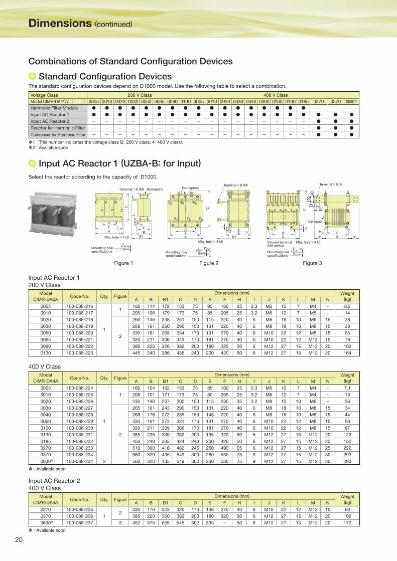
Select the reactor according to the capacity of D1000.
Combinations of Standard Confi guration Devices
Figure 1 Figure 2 Figure 3
NameplateTerminal × 6 (M)
Mtg. hole × 4 (J)
Mounting holespecifications
U
X
V
Y
W
Z
C
H
E
B
B1
D
F
A
I
L
K
Mounting holespecifications
Terminal × 6 (M)Nameplate
U
X Y
V W
Z
H
C
DFA
EB
B1
I
L KN
Mtg. hole × 4 (J)
Mounting holespecifications
Mtg. hole × 4 (J)
YXU
Ground terminal(M8 screw)
Terminal × 6 (M)
KL
4025
100
40
AD
BE
H
B1 B1
CI
ZWV
Nameplate
Model
CIMR-DA4ACode No. Qty. Figure
Dimensions (mm) Weight
(kg)A B B1 C D E F H I J K L M N
0005 100-088-224
1
1
160 104 162 133 75 85 160 25 2.3 M6 10 7 M4 − 7.1
0010 100-088-225 206 101 171 173 75 80 205 25 3.2 M6 12 7 M4 − 13
0020 100-088-226 230 146 207 200 150 115 230 35 3.2 M8 10 10 M6 − 26
0030 100-088-227
2
265 161 243 290 150 131 220 40 6 M8 18 10 M8 15 34
0040 100-088-228 268 176 272 285 150 146 220 40 6 M8 18 10 M8 15 44
0060 100-088-229 330 161 273 331 170 131 270 40 6 M10 22 12 M8 15 56
0100 100-088-230 320 211 309 366 170 181 270 40 6 M10 22 12 M8 15 87
0130 100-088-231 385 235 330 382 200 195 320 50 6 M12 27 15 M12 20 122
0185 100-088-232 450 240 335 424 240 200 420 50 6 M12 27 15 M12 20 150
0270 100-088-233 510 300 410 482 245 250 490 65 6 M12 27 15 M12 25 222
0370 100-088-234 560 320 435 549 300 260 530 75 9 M12 27 15 M12 30 293
0630* 100-088-234 2 560 320 435 549 300 260 530 75 9 M12 27 15 M12 30 293
Model
CIMR-DA4ACode No. Qty. Figure
Dimensions (mm) Weight
(kg)A B B1 C D E F H I J K L M N
0270 100-088-235
12
330 176 323 326 170 146 270 40 6 M10 22 12 M12 15 60
0370 100-088-236 385 220 350 382 200 180 320 50 6 M12 27 15 M12 20 102
0630* 100-088-237 3 452 375 635 545 302 335 − 50 6 M12 27 15 M12 20 172
Model
CIMR-DA2ACode No. Qty. Figure
Dimensions (mm) Weight
(kg)A B B1 C D E F H I J K L M N
0005 100-088-216
1
1160 114 172 133 75 95 160 25 2.3 M6 10 7 M4 − 8.2
0010 100-088-217 205 106 179 173 75 85 205 25 3.2 M6 12 7 M5 − 14
0020 100-088-218
2
266 146 238 251 150 115 220 40 6 M8 18 10 M6 15 28
0030 100-088-219 268 161 260 290 150 131 220 40 6 M8 18 10 M8 15 38
0050 100-088-220 330 161 268 334 170 131 270 40 6 M10 22 12 M8 15 65
0065 100-088-221 320 211 306 343 170 181 270 40 6 M10 22 12 M12 15 79
0090 100-088-222 380 220 320 382 200 180 320 50 6 M12 27 15 M12 20 102
0130 100-088-223 445 240 386 436 240 200 420 50 6 M12 27 15 M12 20 164
Input AC Reactor 1
200 V Class
400 V Class
Input AC Reactor 2
400 V Class
Standard Confi guration DevicesThe standard confi guration devices depend on D1000 model. Use the following table to select a combination.
Input AC Reactor 1 (UZBA-B: for Input)
Voltage Class 200 V Class 400 V Class
Model CIMR-DA A 0005 0010 0020 0030 0050 0065 0090 0130 0005 0010 0020 0030 0040 0060 0100 0130 0185 0270 0370 0630*2
Harmonic Filter Module − − −Input AC Reactor 1
Input AC Reactor 2 − − − − − − − − − − − − − − − − −Reactor for Harmonic Filter − − − − − − − − − − − − − − − − −Condenser for Harmonic Filter − − − − − − − − − − − − − − − − −
*1
*1 : This number indicates the voltage class (2: 200 V class, 4: 400 V class).
*2 : Available soon
* : Available soon
* : Available soon
21
Featu
res
Ap
plic
ation
Exam
ple
sA
pp
licab
le
Mo
dels
Sta
nd
ard
S
pecifi c
atio
ns
Sele
cting
the
Cap
acity
Co
nnectio
n
Dia
gra
mTe
rmin
al
Functio
ns
Fully
- Enclo
sed
D
esig
nP
erip
hera
l Dev
ices
an
d O
ptio
nsA
pp
licatio
n
No
tes
Glo
bal S
erv
ice
Netw
ork
Dim
ensio
ns
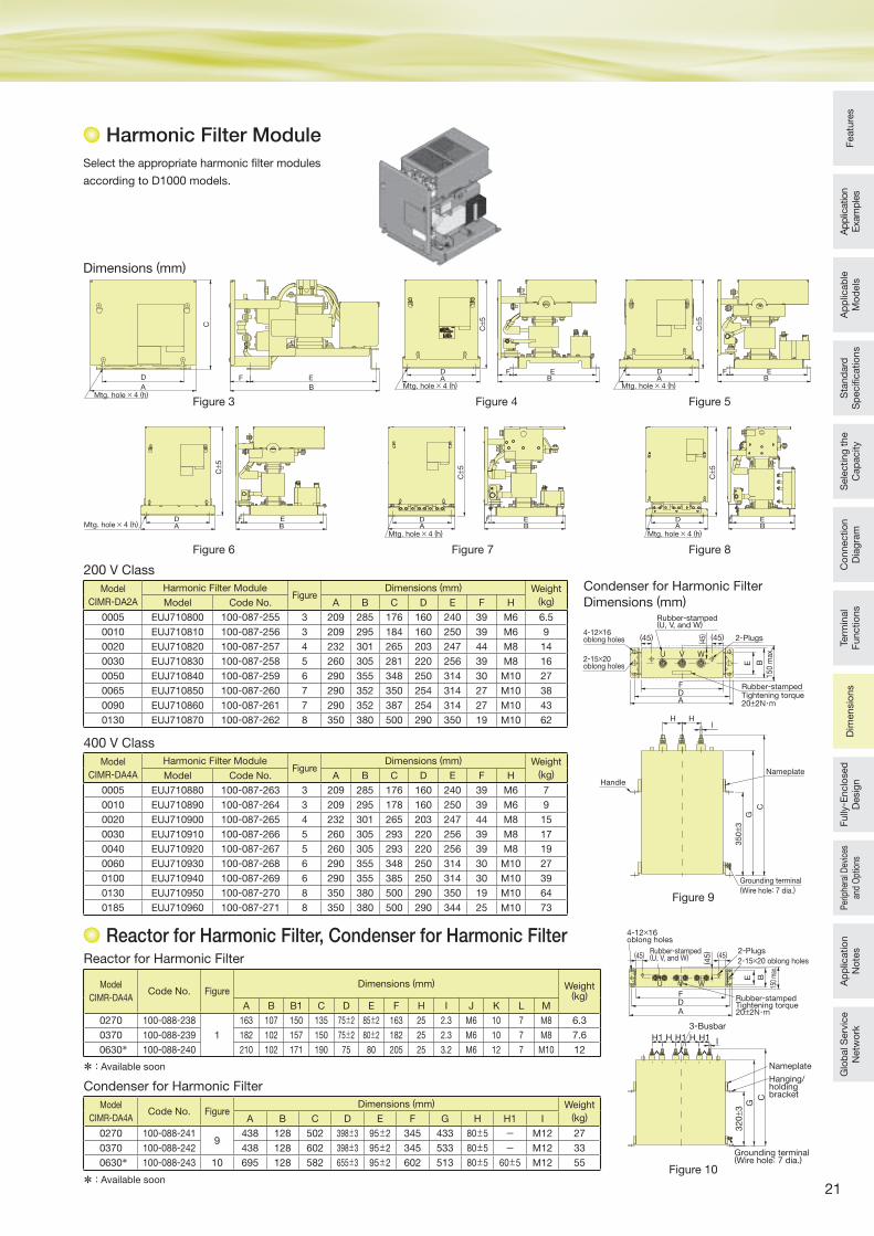
Harmonic Filter Module
D
AMtg. hole × 4 (h)
C
EB
F
Model
CIMR-DA4ACode No. Figure
Dimensions (mm) Weight(kg)
A B B1 C D E F H I J K L M
0270 100-088-238
1
163 107 150 135 75±2 85±2 163 25 2.3 M6 10 7 M8 6.3
0370 100-088-239 182 102 157 150 75±2 80±2 182 25 2.3 M6 10 7 M8 7.6
0630* 100-088-240 210 102 171 190 75 80 205 25 3.2 M6 12 7 M10 12
Model
CIMR-DA4ACode No. Figure
Dimensions (mm) Weight
(kg)A B C D E F G H H1 I
0270 100-088-2419
438 128 502 398±3 95±2 345 433 80±5 − M12 27
0370 100-088-242 438 128 602 398±3 95±2 345 533 80±5 − M12 33
0630* 100-088-243 10 695 128 582 655±3 95±2 602 513 80±5 60±5 M12 55
Dimensions (mm)
Condenser for Harmonic Filter
Dimensions (mm)
Select the appropriate harmonic fi lter modules
according to D1000 models.
Figure 3
Figure 6
Figure 5Figure 4
Figure 8Figure 7
Model
CIMR-DA2A
Harmonic Filter ModuleFigure
Dimensions (mm) Weight
(kg)Model Code No. A B C D E F H
0005 EUJ710800 100-087-255 3 209 285 176 160 240 39 M6 6.5
0010 EUJ710810 100-087-256 3 209 295 184 160 250 39 M6 9
0020 EUJ710820 100-087-257 4 232 301 265 203 247 44 M8 14
0030 EUJ710830 100-087-258 5 260 305 281 220 256 39 M8 16
0050 EUJ710840 100-087-259 6 290 355 348 250 314 30 M10 27
0065 EUJ710850 100-087-260 7 290 352 350 254 314 27 M10 38
0090 EUJ710860 100-087-261 7 290 352 387 254 314 27 M10 43
0130 EUJ710870 100-087-262 8 350 380 500 290 350 19 M10 62
Model
CIMR-DA4A
Harmonic Filter ModuleFigure
Dimensions (mm) Weight
(kg)Model Code No. A B C D E F H
0005 EUJ710880 100-087-263 3 209 285 176 160 240 39 M6 7
0010 EUJ710890 100-087-264 3 209 295 178 160 250 39 M6 9
0020 EUJ710900 100-087-265 4 232 301 265 203 247 44 M8 15
0030 EUJ710910 100-087-266 5 260 305 293 220 256 39 M8 17
0040 EUJ710920 100-087-267 5 260 305 293 220 256 39 M8 19
0060 EUJ710930 100-087-268 6 290 355 348 250 314 30 M10 27
0100 EUJ710940 100-087-269 6 290 355 385 250 314 30 M10 39
0130 EUJ710950 100-087-270 8 350 380 500 290 350 19 M10 64
0185 EUJ710960 100-087-271 8 350 380 500 290 344 25 M10 73
200 V Class
Reactor for Harmonic Filter
Condenser for Harmonic Filter
400 V Class
Mtg. hole × 4 (h)
D F EBA
C± 5
Mtg. hole × 4 (h)
D F EBA
C± 5
Mtg. hole × 4 (h)D EFA B
C± 5
Mtg. hole × 4 (h)
D F EA B
C± 5
Mtg. hole × 4 (h)
D F EA B
C± 5
G
C
35
0± 3
15
0 m
ax.
BE
ADF
Rubber-stamped (U, V, and W)
2-Plugs(45) (45)
( 45)
Handle
Nameplate
Grounding terminal(Wire hole: 7 dia.)
H HI
VU W
4-12×16 oblong holes
2-15×20 oblong holes
Tightening torque 20±2N・m
Rubber-stamped
Figure 9
Figure 10
Reactor for Harmonic Filter, Condenser for Harmonic Filter
C
32
0± 3
G
H1HH1HH1
3-Busbar
I
Nameplate
Hanging/holding bracket
( 45
) (45)(45)
FDA
4-12×16oblong holes
2-15×20 oblong holes
2-Plugs
Grounding terminal(Wire hole: 7 dia.)
Rubber-stamped (U, V, and W)
WVU
Rubber-stampedTightening torque20±2N・m
150
max
.
BE
* : Available soon
* : Available soon
22
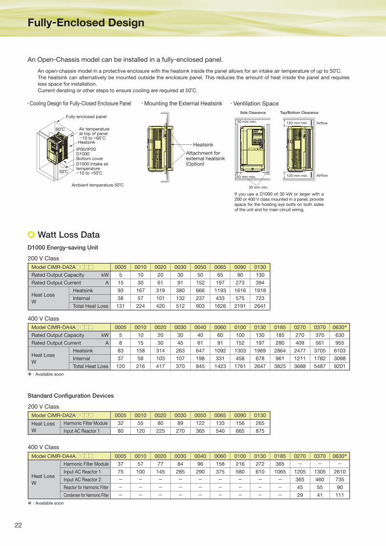
Fully-Enclosed Design
Watt Loss Data
Model CIMR-DA2A 0005 0010 0020 0030 0050 0065 0090 0130
Rated Output Capacity kW 5 10 20 30 50 65 90 130
Rated Output Current A 15 30 61 91 152 197 273 394
Heat Loss
W
Heatsink 93 167 319 380 666 1193 1616 1918
Internal 38 57 101 132 237 433 575 723
Total Heat Loss 131 224 420 512 903 1626 2191 2641
Model CIMR-DA4A 0005 0010 0020 0030 0040 0060 0100 0130 0185 0270 0370 0630*
Rated Output Capacity kW 5 10 20 30 40 60 100 130 185 270 370 630
Rated Output Current A 8 15 30 45 61 91 152 197 280 409 561 955
Heat Loss
W
Heatsink 83 158 314 263 647 1092 1303 1969 2864 2477 3705 6103
Internal 37 58 103 107 198 331 458 678 961 1211 1782 3098
Total Heat Loss 120 216 417 370 845 1423 1761 2647 3825 3688 5487 9201
Model CIMR-DA2A 0005 0010 0020 0030 0050 0065 0090 0130
Heat Loss
W
Harmonic Filter Module 32 55 80 89 122 133 156 265
Input AC Reactor 1 80 120 225 270 365 540 665 875
Model CIMR-DA4A 0005 0010 0020 0030 0040 0060 0100 0130 0185 0270 0370 0630*
Heat Loss
W
Harmonic Filter Module 37 57 77 84 96 158 216 272 365 - - -Input AC Reactor 1 75 100 145 285 290 375 580 610 1065 1205 1305 2610
Input AC Reactor 2 - - - - - - - - - 365 460 735
Reactor for Harmonic Filter - - - - - - - - - 45 55 90
Condenser for Harmonic Filter - - - - - - - - - 29 41 111
200 V Class
400 V Class
400 V Class
200 V Class
D1000 Energy-saving Unit
Standard Confi guration Devices
Cooling Design for Fully-Closed Enclosure Panel Ventilation Space
An Open-Chassis model can be installed in a fully-enclosed panel.
If you use a D1000 of 30 kW or larger with a 200 or 400 V class mounted in a panel, provide space for the hoisting eye bolts on both sides of the unit and for main circuit wiring.
Fully-enclosed panel
60˚C
50˚C
Air temperatureat top of panel-10 to +60°C
IP00/IP20D1000
D1000 Intake airtemperature-10 to +50˚C
Ambient temperature 50˚C
Bottom cover
HeatsinkHeatsink
Attachment forexternal heatsink(Option)
120 mm min. Airflow
Airflow120 mm min.
50 mm min.
Side Clearance Top/Bottom Clearance
50 mm min.
30 mm min.
An open-chassis model in a protective enclosure with the heatsink inside the panel allows for an intake air temperature of up to 50˚C.
The heatsink can alternatively be mounted outside the enclosure panel. This reduces the amount of heat inside the panel and requires
less space for installation.
Current derating or other steps to ensure cooling are required at 50˚C.
Mounting the External Heatsink
* : Available soon
* : Available soon
23
Featu
res
Ap
plic
ation
Exam
ple
sA
pp
licab
le
Mo
dels
Sta
nd
ard
S
pecifi c
atio
ns
Sele
cting
the
Cap
acity
Co
nnectio
n
Dia
gra
mTe
rmin
al
Functio
ns
Dim
ensio
ns
Per
iphe
ral D
evic
es
and
Opt
ions
Ap
plic
atio
n
No
tes
Glo
bal S
erv
ice
Netw
ork
Fully
- Enclo
sed
D
esig
n
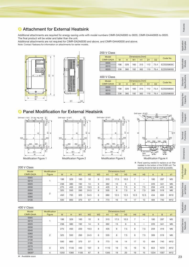
Attachment for External Heatsink
Additional attachments are required for energy-saving units with model numbers CIMR-DA2A0005 to 0020, CIMR-DA4A0005 to 0020.
The final product will be wider and taller than the unit.
Additional attachments are not required for CIMR-DA2A0030 and above, and CIMR-DA4A0030 and above. Note: Contact Yaskawa for information on attachments for earlier models.
Model
CIMR-DA2A
Dimensions (mm)Code No.
W H W1 H1 D1 D2
0005198 329 160 315 112 73.4 EZZ020800C
0010
0020 238 380 192 362 119 76.4 EZZ020800D
Model
CIMR-DA4A
Dimensions (mm)Code No.
W H W1 H1 D1 D2
0005198 329 160 315 112 73.4 EZZ020800C
0010
0020 238 380 192 362 119 76.4 EZZ020800D
200 V Class
400 V Class
HH1
W1W
D1 D2
W3 W3
H2
H3
H4
H4
W2 W2
W1
W
A
Drill hole × 4 (d1) 2-5 dia. mtg. hole
b
b
a a
a a
B H1
H
Modifi cation Figure 1
W3 W3
H2
H4
H5
H3
W2 W2
W1
W
A
Drill hole × 6 (d1)
b
a
a a a
a a
B H1
H
WW1 W2W2
A W3W3
330 440 330
H3
H1
H
352 200 380 200
BH
21
20
150
H4
88
Drill hole × 8 (d1)
H5
18
6
88
16
610
10
88
35 35 35 35
130
216
130
216
Drill hole×8 (M4) (for cover)
* *
Modifi cation Figure 3 Modifi cation Figure 4
W3 W3
H2
H3
H4
H5
W2 W2
W1
W
A
Drill hole × 4 (d1)
a a
a a
B H1
H
Modifi cation Figure 2
Model
CIMR-DA2A
Modifi cation
Figure
Dimensions (mm)
W H W1 W2 W3 H1 H2 H3 H4 H5 A B d1
0005
1198 329 160 10 9 315 17.5 10.5 7 ー 180 287 M5
0010
0020 238 380 192 14 9 362 13 8 9 ー 220 341 M6
0030
2
275 450 220 19.5 8 435 8 7.5 8 7.5 259 419 M6
0050 325 550 260 24.5 8 535 8 7.5 8 7.5 309 519 M6
0065450 705 325 54.5 8 680 12.5 12.5 12.5 12.5 434 655 M10
0090
0130 500 800 370 57 8 773 16 14 17 13 484 740 M12
Model
CIMR-DA4A
Modifi cation
Figure
Dimensions (mm)
W H W1 W2 W3 H1 H2 H3 H4 H5 A B d1
0005
1198 329 160 10 9 315 17.5 10.5 7 ー 180 287 M5
0010
0020 238 380 192 14 9 362 13 8 9 ー 220 341 M6
0030
2
275 450 220 19.5 8 435 8 7.5 8 7.5 259 419 M60040
0060325 550 260 24.5 8 535 8 7.5 8 7.5 309 519 M6
0100
0130500 800 370 57 8 773 16 14 17 13 484 740 M12
0185
02703 670 1140 440 107 8 1110 19 15 19 15 654 1072 M12
0370
0630* 4 1250 1380 1100 67 8 1345 19 20 19 15 1234 1307 M12
200 V Class
400 V Class
Panel Modifi cation for External Heatsink
* : Panel opening needed to replace an air filter installed to the bottom of the D1000 unit. The opening should be kept as small as possible.
* : Available soon
24
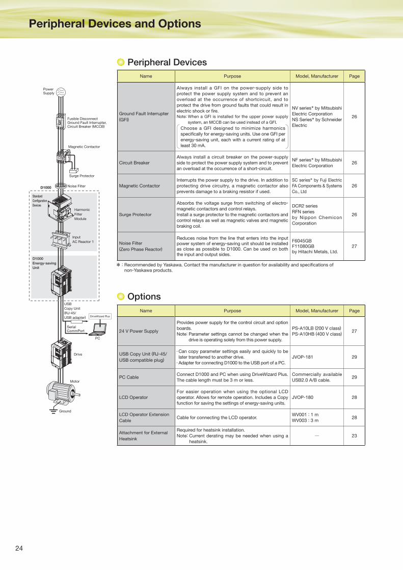
Peripheral Devices and Options
Name Purpose Model, Manufacturer Page
Ground Fault Interrupter
(GFI)
Always install a GFI on the power-supply side to
protect the power supply system and to prevent an
overload at the occurrence of shortcircuit, and to
protect the drive from ground faults that could result in
electric shock or fi re.Note: When a GFI is installed for the upper power supply
system, an MCCB can be used instead of a GFI.
Choose a GFI designed to minimize harmonics
specifi cally for energy-saving units. Use one GFI per
energy-saving unit, each with a current rating of at
least 30 mA.
NV series* by Mitsubishi
Electric Corporation
NS Series* by Schneider
Electric
26
Circuit Breaker
Always install a circuit breaker on the power-supply
side to protect the power supply system and to prevent
an overload at the occurrence of a short-circuit.
NF series* by Mitsubishi
Electric Corporation26
Magnetic Contactor
Interrupts the power supply to the drive. In addition to
protecting drive circuitry, a magnetic contactor also
prevents damage to a braking resistor if used.
SC series* by Fuji Electric
FA Components & Systems
Co., Ltd
26
Surge Protector
Absorbs the voltage surge from switching of electro-
magnetic contactors and control relays.
Install a surge protector to the magnetic contactors and
control relays as well as magnetic valves and magnetic
braking coil.
DCR2 series
RFN series
by Nippon Chemicon
Corporation
26
Noise Filter
(Zero Phase Reactor)
Reduces noise from the line that enters into the input power system of energy-saving unit should be installed as close as possible to D1000. Can be used on both the input and output sides.
F6045GBF11080GBby Hitachi Metals, Ltd.
27
Name Purpose Model, Manufacturer Page
24 V Power Supply
Provides power supply for the control circuit and option
boards.
Note: Parameter settings cannot be changed when the
drive is operating solely from this power supply.
PS-A10LB (200 V class)
PS-A10HB (400 V class)27
USB Copy Unit (RJ-45/
USB compatible plug)
Can copy parameter settings easily and quickly to be
later transferred to another drive.
Adapter for connecting D1000 to the USB port of a PC.
JVOP-181 29
PC CableConnect D1000 and PC when using DriveWizard Plus.
The cable length must be 3 m or less.
Commercially available
USB2.0 A/B cable.29
LCD Operator
For easier operation when using the optional LCD
operator. Allows for remote operation. Includes a Copy
function for saving the settings of energy-saving units.
JVOP-180 28
LCD Operator Extension
CableCable for connecting the LCD operator.
WV001 : 1 m
WV003 : 3 m28
Attachment for External
Heatsink
Required for heatsink installation.
Note: Current derating may be needed when using a
heatsink.
─ 23
* : Recommended by Yaskawa. Contact the manufacturer in question for availability and specifi cations of non-Yaskawa products.
PowerSupply
Magnetic Contactor
Surge Protector
Noise FilterD1000
Harmonic
Filter
Module
USB
Copy Unit(RJ-45/
USB adapter) DriveWizard Plus
PC
SerialCommPort
Input
AC Reactor 1
Standard
Configuration
Devices
D1000
Energy-saving
Unit
Fusible DisconnectGround Fault Interrupter,Circuit Breaker (MCCB)
Drive
Motor
Ground
Peripheral Devices
Options
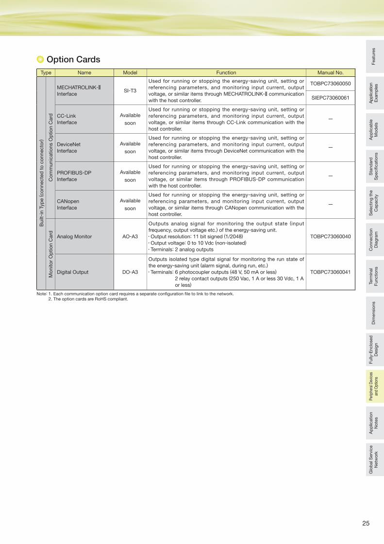
25
Featu
res
Ap
plic
ation
Exam
ple
sA
pp
licab
le
Mo
dels
Sta
nd
ard
S
pecifi c
atio
ns
Sele
cting
the
Cap
acity
Co
nnectio
n
Dia
gra
mTe
rmin
al
Functio
ns
Dim
ensio
ns
Fully
- Enclo
sed
D
esig
nA
pp
licatio
n
No
tes
Glo
bal S
erv
ice
Netw
ork
Per
iphe
ral D
evic
es
and
Opt
ions
Option Cards
Type Name Model Function Manual No.
Built
- in T
yp
e (co
nnecte
d t
o c
onnecto
r)
Co
mm
unic
atio
ns O
ptio
n C
ard
MECHATROLINK-2
InterfaceSI-T3
Used for running or stopping the energy-saving unit, setting or
referencing parameters, and monitoring input current, output
voltage, or similar items through MECHATROLINK-2 communication
with the host controller.
TOBPC73060050
SIEPC73060061
CC-Link
Interface
Available
soon
Used for running or stopping the energy-saving unit, setting or
referencing parameters, and monitoring input current, output
voltage, or similar items through CC-Link communication with the
host controller.
ー
DeviceNet
Interface
Available
soon
Used for running or stopping the energy-saving unit, setting or
referencing parameters, and monitoring input current, output
voltage, or similar items through DeviceNet communication with the
host controller.
ー
PROFIBUS-DP
Interface
Available
soon
Used for running or stopping the energy-saving unit, setting or
referencing parameters, and monitoring input current, output
voltage, or similar items through PROFIBUS-DP communication
with the host controller.
ー
CANopen
Interface
Available
soon
Used for running or stopping the energy-saving unit, setting or
referencing parameters, and monitoring input current, output
voltage, or similar items through CANopen communication with the
host controller.
ー
Mo
nito
r O
ptio
n C
ard
Analog Monitor AO-A3
Outputs analog signal for monitoring the output state (input
frequency, output voltage etc.) of the energy-saving unit.
Output resolution: 11 bit signed (1/2048)
Output voltage: 0 to 10 Vdc (non-isolated)
Terminals: 2 analog outputs
TOBPC73060040
Digital Output DO-A3
Outputs isolated type digital signal for monitoring the run state of
the energy-saving unit (alarm signal, during run, etc.)
Terminals: 6 photocoupler outputs (48 V, 50 mA or less)
2 relay contact outputs (250 Vac, 1 A or less 30 Vdc, 1 A
or less)
TOBPC73060041
Note: 1. Each communication option card requires a separate confi guration fi le to link to the network.2. The option cards are RoHS compliant.
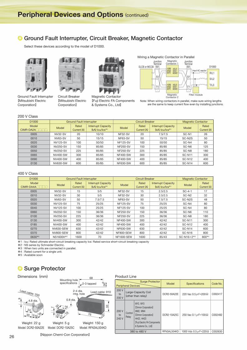
26
Peripheral Devices and Options (continued)
Ground Fault Interrupter, Circuit Breaker, Magnetic Contactor
Select these devices according to the model of D1000.
Circuit Breaker
【Mitsubishi Electric
Corporation】
Magnetic Contactor
【Fuji Electric FA Components
& Systems Co., Ltd】
D1000
S1
R1
T1
S1
R1
T1
R/L1
S/L2
T/L3
1(R)2(S)3(T)
4(U)5(V)6(W)
1(R)2(S)3(T)
4(U)5(V)6(W)
ELCB or MCCB
JunctionTerminal
JunctionTerminal
MagneticContactor 1
Input AC reactor
Filter moduleMagneticContactor 2
Wiring a Magnetic Contactor in Parallel
Note: When wiring contactors in parallel, make sure wiring lengths are the same to keep current fl ow even by installing junctions.
Ground Fault Interrupter
【Mitsubishi Electric
Corporation】
D1000 Ground Fault Interrupter Circuit Breaker Magnetic Contactor
Model
CIMR-DA4AModel
Rated
Current (A)
Interrupt Capacity
(kA) Icu/Ics*1Model
Rated
Current (A)
Interrupt Capacity
(kA) Icu/Ics*1Model
Rated
Current (A)
0005 NV32-SV 15 5/5 NF32-SV 15 2.5/2.5 SC-4-1 17
0010 NV32-SV 30 5/5 NF32-SV 30 2.5/2.5 SC-N2 32
0020 NV63-SV 50 7.5/7.5 NF63-SV 50 7.5/7.5 SC-N2S 48
0030 NV125-SV 75 25/25 NF125-SV 75 25/25 SC-N4 80
0040 NV125-SV 100 25/25 NF125-SV 100 25/25 SC-N4 80
0060 NV250-SV 150 36/36 NF250-SV 150 36/36 SC-N6 110
0100 NV250-SV 225 36/36 NF250-SV 225 36/36 SC-N8 180
0130 NV400-SW 300 42/42 NF400-SW 300 42/42 SC-N11 300
0185 NV400-SW 400 42/42 NF400-SW 400 42/42 SC-N12 400
0270 NV630-SEW 630 42/42 NF630-SW 630 42/42 SC-N14 600
0370 NV800-SEW 800 42/42 NF800-SEW 800 42/42 SC-N16 800
0630*5 NS1600H*2 1600 70 NF1600-SEW 1600 85/43 SC-N16×2*3 800*4
D1000 Ground Fault Interrupter Circuit Breaker Magnetic Contactor
Model
CIMR-DA2AModel
Rated
Current (A)
Interrupt Capacity
(kA) Icu/Ics*1Model
Rated
Current (A)
Interrupt Capacity
(kA) Icu/Ics*1Model
Rated
Current (A)
0005 NV32-SV 20 10/10 NF32-SV 20 7.5/7.5 SC-N1 26
0010 NV63-SV 50 15/15 NF63-SV 50 15/15 SC-N2S 50
0020 NV125-SV 100 50/50 NF125-SV 100 50/50 SC-N4 80
0030 NV250-SV 150 85/85 NF250-SV 150 85/85 SC-N6 125
0050 NV250-SV 225 85/85 NF250-SV 225 85/85 SC-N8 180
0065 NV400-SW 300 85/85 NF400-SW 300 85/85 SC-N11 300
0090 NV400-SW 400 85/85 NF400-SW 400 85/85 SC-N12 400
0130 NV630-SW 600 85/85 NF630-SW 600 85/85 SC-N14 600
400 V Class
200 V Class
*1 : Icu: Rated ultimate short-circuit breaking capacity Ics: Rated service short-circuit breaking capacity
*2 : NS series by Schneider Electric.
*3 : When two units are connected in parallel.
*4 : Rated current for a single unit.
*5 : Available soon
Lead cable: 910
Mounting holespecifications 2-3 tapped
34
68
76
26
33
Model: RFN3AL504KD
Weight: 150 g
Model: DCR2-10A25C
Weight: 5 g
Lead cable: 250
30
24
36
9
Model: DCR2-50A22E
Weight: 22 g
4.8 dia.
16
7
22.5
30 16
0.8 dia.
2-4 dia.mtg. hole
18 dia.
【Nippon Chemi-Con Corporation】
Surge Protector
Peripheral DevicesModel Specifi cations Code No.
200 V
to
230 V
Large-Capacity Coil
(other than relay)DCR2-50A22E 220 Vac 0.5 μ F+200Ω C002417
200 V
to
240 V
Control
Relay
MY2,MY3
【Omron Corporation】MM2,MM4
【Omron Corporation】HH22,HH23
【Fuji Electric FA Components
& Systems Co., Ltd】
DCR2-10A25C 250 Vac 0.1 μ F+100Ω C002482
380 to 480 V RFN3AL504KD 1000 Vdc 0.5 μ F+220Ω C002630
Dimensions (mm) Product Line
Surge Protector
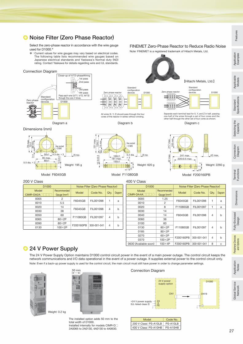
27
Featu
res
Ap
plic
ation
Exam
ple
sA
pp
licab
le
Mo
dels
Sta
nd
ard
S
pecifi c
atio
ns
Sele
cting
the
Cap
acity
Co
nnectio
n
Dia
gra
mTe
rmin
al
Functio
ns
Dim
ensio
ns
Fully
- Enclo
sed
D
esig
nA
pp
licatio
n
No
tes
Glo
bal S
erv
ice
Netw
ork
Per
iphe
ral D
evic
es
and
Opt
ions
Noise Filter (Zero Phase Reactor)
241 max.
220±0.5 max.
217
max.
155
min
.
42 max.
7
42
max.
14
Select the zero-phase reactor in accordance with the wire gauge
used for D1000.*
* : Current values for wire gauges may vary based on electrical codes.The following table lists recommended wire gauges based on Japanese electrical standards and Yaskawa’s Normal duty (ND) rating. Contact Yaskawa for details regarding wire and UL standards.
FINEMET Zero-Phase Reactor to Reduce Radio NoiseNote: FINEMET is a registered trademark of Hitachi Metals, Ltd.
D1000
Standard configuration devices
Close-up of V/T2-phaseWiring
Pass each wire (U/T1, V/T2, W/T3)through the core 4 times.
1st pass
2nd pass
3rd pass
4th pass
Zero phase reactor
Connection Diagram
D1000
All wires (X, Y, Z) should pass through the four cores of the reactor in series without winding.
Zero phase reactor
Standard configuration devices
Model F6045GB
Diagram b
78
max.
39
min
.72± 1
7± 1
12.5± 0
.3
50±1
80±195 max.
26 max.
Hex socket× 3 (M4)
4.5 dia. × 3
5.5 dia. × 2
131
max.
74
min
.
124± 1
12
.5± 0
.3
26 max.100±1
181 max.
150±1
Hex socket× 3 (M5)
8
12
5.2 dia. × 3
20± 1
Dimensions (mm)
Weight: 195 g Weight: 620 g
Model F11080GB
Diagram a
【Hitachi Metals, Ltd.】
Weight: 2260 g
Model F200160PB
Standard configuration devices D1000Zero phase reactor
Separate each terminal lead for X, Y, and Z in half, passing one half of the wires through a set of four cores and the other half through the other set of four cores as shown.
Diagram c
D1000 Noise Filter (Zero Phase Reactor)
Model
CIMR-DA2A
Recommended
Gauge (mm2)Model Code No. Qty. Diagram
0005 2F6045GB FIL001098 1 a
0010 5.5
0020 14F6045GB FIL001098 4 b
0030 38
0050 60F11080GB FIL001097 4 b
0065 80×2P
0090 80×2PF200160PB 300-001-041 4 b
0130 100×2P
D1000 Noise Filter (Zero Phase Reactor)
Model
CIMR-DA4A
Recommended
Gauge (mm2)Model Code No. Qty. Diagram
0005 1.25F6045GB FIL001098 1 a
0010 2
0020 8 F11080GB FIL001097 1 a
0030 14
F6045GB FIL001098 4 b0040 14
0060 38
0100 60
F11080GB FIL001097 4 b0130 80×2P
0185 80×2P
0270 60×2PF200160PB 300-001-041 4 b
0370 100×2P
0630 (Available soon) 100×4P F200160PB 300-001-041 8 c
200 V Class 400 V Class
24 V Power SupplyThe 24 V Power Supply Option maintains D1000 control circuit power in the event of a main power outage. The control circuit keeps the network communications and I/O data operational in the event of a power outage. It supplies external power to the control circuit only. Note: Even if a back-up power supply is used for the control circuit, the main circuit must still have power in order to change parameter settings.
D1000
240FE
24 V powersupply option
CN19CN1
+24 V power supply(UL-listed class 2)
Connection Diagram
The installed option adds 50 mm to the total width of D1000.Installed internally for models CIMR-D2A0065 to 2A0130, 4A0130 to 4A0630.
Model Code No.
200 V Class: PS-A10LB PS-A10LB
400 V Class: PS-A10HB PS-A10HB
50 mm
Weight: 0.2 kg
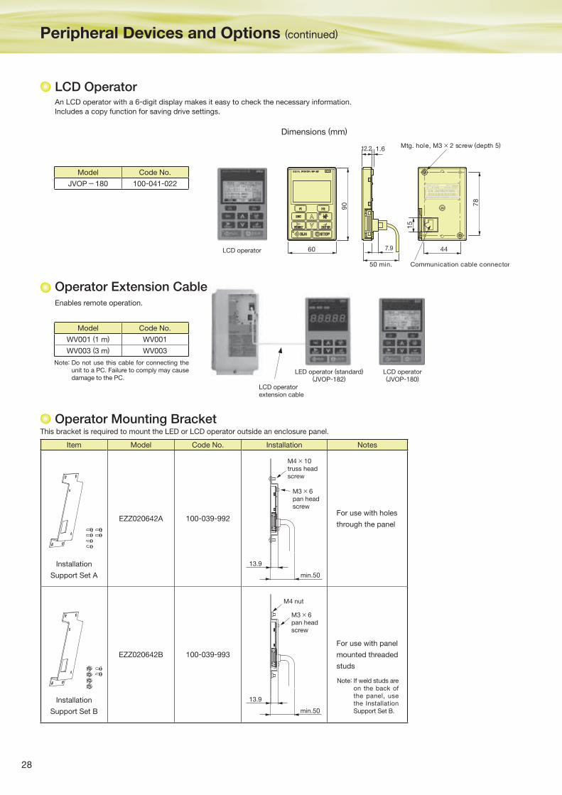
28
LCD Operator
Peripheral Devices and Options (continued)
An LCD operator with a 6-digit display makes it easy to check the necessary information.
Includes a copy function for saving drive settings.
Dimensions (mm)
90 78
60 7.9
12.2 1.6
44
15
50 min.
Mtg. hole, M3 × 2 screw (depth 5)
Communication cable connector
Model Code No.
JVOP-180 100-041-022
LCD operator
Model Code No.
WV001 (1 m) WV001
WV003 (3 m) WV003
This bracket is required to mount the LED or LCD operator outside an enclosure panel.
Item Model Code No. Installation Notes
Installation
Support Set A
EZZ020642A 100-039-992For use with holes
through the panel
Installation
Support Set B
EZZ020642B 100-039-993
For use with panel
mounted threaded
studs
13.9
min.50
M4 × 10truss headscrew
M3 × 6pan headscrew
13.9
min.50
M3 × 6pan headscrew
M4 nut
Note: If weld studs are on the back of the panel, use the Installation Support Set B.
Enables remote operation.
LCD operator(JVOP-180)
LED operator (standard)(JVOP-182)
LCD operatorextension cable
Note: Do not use this cable for connecting the unit to a PC. Failure to comply may cause damage to the PC.
Operator Extension Cable
Operator Mounting Bracket
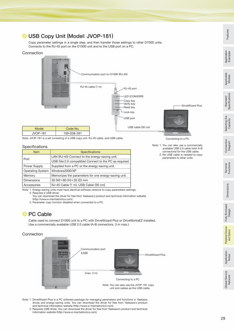
29
Featu
res
Ap
plic
ation
Exam
ple
sA
pp
licab
le
Mo
dels
Sta
nd
ard
S
pecifi c
atio
ns
Sele
cting
the
Cap
acity
Co
nnectio
n
Dia
gra
mTe
rmin
al
Functio
ns
Dim
ensio
ns
Fully
- Enclo
sed
D
esig
nA
pp
licatio
n
No
tes
Glo
bal S
erv
ice
Netw
ork
Per
iphe
ral D
evic
es
and
Opt
ions
USB Copy Unit (Model: JVOP-181)
PC Cable
Copy parameter settings in a single step, and then transfer those settings to other D1000 units.
Connects to the RJ-45 port on the D1000 unit and to the USB port on a PC.
Model Code No.
JVOP-181 100-038-281
Item Specifi cations
PortLAN (RJ-45) Connect to the energy-saving unit.
USB (Ver.2.0 compatible) Connect to the PC as required.
Power Supply Supplied from a PC or the energy-saving unit.
Operating System Windows2000/XP
Memory Memorizes the parameters for one energy-saving unit.
Dimensions 30 (W)×80 (H)×20 (D) mm
Accessories RJ-45 Cable (1 m), USB Cable (30 cm)
Specifi cations
Note: 1. Energy-saving units must have identical software versions to copy parameters settings.2. Requires a USB driver.
You can download the driver for free from Yaskawa’s product and technical information website (http://www.e-mechatronics.com).
3. Parameter copy function disabled when connected to a PC.
Note: JVOP-181 is a set consisting of a USB copy unit, RJ-45 cable, and USB cable.
Connection
RJ-45 cable (1 m)
LED (COM/ERR)
Copy keyVerify key
Read key
USB port
USB cable (30 cm)
RJ-45 port
Lock key
Communication port on D1000 (RJ-45)
DriveWizard Plus
Connecting to a PC
Connecting to a PC
Note: 1. You can also use a commercially available USB 2.0 cable (with A-B connectors) for the USB cable.
2. No USB cable is needed to copy parameters to other units.
Note: You can also use the JVOP-181 copy unit and cables as the USB cable.
Connection
Cable used to connect D1000 unit to a PC with DriveWizard Plus or DriveWorksEZ installed.
Use a commercially available USB 2.0 cable (A-B connectors, 3 m max.).
(max. 3 m)
DriveWizard Plus
Communication port
(USB)
Note: 1. DriveWizard Plus is a PC software package for managing parameters and functions in Yaskawa drives and energy-saving units. You can download the driver for free from Yaskawa’s product and technical information website (http://www.e-mechatronics.com).
2. Requires USB driver. You can download the driver for free from Yaskawa’s product and technical information website (http://www.e-mechatronics.com).
30
Application Precautions
Application Notes
prevent an external fault from being detected
when the power supply is turned on.
Example 2 Restarting the System for Momentary Power
Losses
Change the setting for the external base
block input terminal S8 on the drive from the
default setting of an N.O. contact to an N.C.
contact.
Connect the During MC ON output from
D1000 to the external base block input on
the drive. Set restarting for momentary
power losses in the drive.
Note: For V1000/J1000, an external base
block is not set in the default
settings. Set an external base block
(N.C.) for one of the multi-function
input terminals.
Example 3 Inputting a Run Commands to the Drive
Always input Run Commands to the drive
while D1000 is operating. You can check
the operating status of D1000 with a During
Run 1 signal on a multi-function output. For
an example of a drive sequence, refer to
Standard D1000 Connection Diagram.
■ Wiring Check
Do not short the output terminals or apply voltage to
output terminals (U/T1, V/T2, W/T3), because this can
cause serious damage to D1000 and the harmonic filter
module.
Be sure to perform a careful check of all sequence
wiring and other connections before turning the power
on. Make sure there are no short circuits on the control
terminals (+V, AC, etc.), because this could damage
D1000.
■ Inspection and Maintenance
Capacitors in D1000 do not immediately discharge after
shutting off the power. After shutting off the power, wait
at least the amount of time specified on the unit and
harmonic filter module before touching any components.
Failure to comply may result in injury to personnel from
electrical shock. Take proper precautions to prevent
burns, because the heatsink of D1000 and the reactors
of the harmonic filter module can get very hot during
operation. When replacing the cooling fan, shut off the
power to D1000 and wait at least 15 minutes to ensure
that the heatsink has cooled down.
Before wiring the harmonic filter module or performing
any maintenance, shut off the power and then wait at
least the amount of time specified on the module to
ensure that the heatsink has cooled down before
touching any components.
■ Wiring
Yaskawa recommends using ring terminals on all
models. Use only the tools recommended by the
terminal manufacturer for crimping.
■ Installation of D1000 Standard Configuration Devices
You must install both D1000 energy-saving unit and the
D1000 standard configuration devices.
■ Replacing Previous Models
If the peripheral devices (i.e., input AC reactors, reactors
for harmonic filters, and capacitors for harmonic filters)
for previous models ( i .e., the VS-656DC3 and
VS-656DC5) are used with D1000, abnormal heating
may occur. Refer to installation instructions and adjust
D1000 accordingly.
Do not use the D1000 standard configuration devices
with the previous models (i.e., VS-656DC3 and
VS-656DC5).
■ D1000 Sequence for Power Loss and Harmonic Filter
Installation
Always sequence the power supply for D1000 so that
the power supply circuit is opened after the operation of
D1000 is stopped.
Always install the specified harmonic filter (harmonic
filter module) to reduce the impact of voltage surges on
other devices when the circuit opens for any unexpected
reason during operation.
■Panel Installation
Install D1000 in a clean environment by either selecting
an area free of airborne oil mist, corrosive gas, flammable
gas, dust, and lint, or install D1000 in a fully-enclosed
panel. If you install D1000 in a panel, determine cooling
methods and panel dimensions so that the ambient
temperature of D1000 and harmonic filter module are
within the allowable temperature range. Do not install
D1000 on wood or other inflammable materials.
■ Installation Direction
Install D1000 upright on a wall.
■ Interlocks
An interlock is required between D1000 and a drive to
stop the drive if D1000 fails or if an error occurs in
D1000. It is also necessary to provide a suitable time to
restart the drive if it will be restarted for momentary
power losses.
Restarting can be timed with the During MC ON signal
that is output from the control circuit terminals of D1000.
Create a sequence to turn off the output from the drive
with an external base block input to the drive or by a
similar means when the During MC ON signal opens.
(Refer to *6 in the Standard Connection Diagram.)
Example 1 Not Restarting for Momentary Power Losses
(Coasting to a Stop for Momentary Power
Losses)
Connect the During MC ON output from
D1000 to the external fault input on the drive.
Use an N.C. input for the external fault input
on the drive and set the drive to detect
external faults only during operation to
31
Featu
res
Ap
plic
ation
Exam
ple
sA
pp
licab
le
Mo
dels
Sta
nd
ard
S
pecifi c
atio
ns
Sele
cting
the
Cap
acity
Co
nnectio
n
Dia
gra
mTe
rmin
al
Functio
ns
Dim
ensio
ns
Fully
- Enclo
sed
D
esig
nP
erip
hera
l Dev
ices
an
d O
ptio
nsG
lob
al S
erv
ice
Netw
ork
Ap
plic
atio
n
No
tes
Peripheral Devices
■ When installing a noise filter on the power supply side,
use a reactor type noise filter without a capacitor (such
as FINEMET zero-phase reactor) and install it after the
MCCB on the power supply side. Do not use a noise
filter with a built-in capacitor, because the harmonic
components may overheat or damage the capacitor.
Install a noise filter recommended by Yaskawa.
■ Installing a Ground Fault Interrupter or an MCCB
Be sure to install an MCCB or an ELCB recommended
by Yaskawa on the power supply side of D1000 to
protect internal circuitry.
The type of MCCB to be selected varies with the power
factor on the power supply side (power supply voltage,
output frequency, load characteristics, and others).
Sometimes a fairly large MCCB may be required due to
the affects of the harmonic current on operating
characteristics. If you use an ELCB that is not
recommended, use one with harmonic suppression
that is designed specifically for drives. A malfunction
may be caused by high-frequency leakage current, so
the rated current of the ELCB must be 30 mA or higher
per drive. If a malfunction occurs in an ELCB without
any protection, adjust the carrier frequency of the drive,
replace the ELCB with one that has countermeasures
against high frequency, or use an ELCB which has a
rated current of 200 mA or higher per drive.
Select an MCCB or an ELCB with a rated capacity
greater than the short-circuit current for the power
supply.
■ Magnetic Contactor for Input Power
Use a magnetic contactor (MC) to ensure that power to
D1000 can be completely shut off when necessary. The
MC should be wired so that it opens when a fault
output terminal is activated.
■ Wire Gauges and Wiring Distance
D1000 phase control can be unstable as a result of
voltage loss across a long cable running between D1000
and the power supply. Make sure that appropriate wire
gauge is used.
The optional LCD operator requires a dedicated cable to
connect to D1000. If an analog signal is sent via the input
terminals to operate D1000, make sure that the cable
between the analog operator and D1000 is not longer
than 50 m, and that the cable is separated from the main
circuit wiring. Use reinforced main circuit and reinforced
relay sequence circuitry to prevent inductance from
surrounding devices.
To use a multi-function analog input, use twisted shielded
pair cables and ground the shield. Refer to the Standard
Connection diagram for details.
■ Generator Power Supplies
Select a generator capacity that has at least about
twice the capacity of the input power supply to D1000.
Contact Yaskawa for details.
Set the deceleration time, load, and other factors so
that the regenerative power from the motor is 10% or
less of the generator capacity.
■ Connecting a Phase-advance Capacitor or Thyristor-
controlled Device to the Power Supply
A phase-advance capacitor is not required for D1000.
Installing a phase-advance capacitor will reduce the
power factor.
For a phase-advance capacitor already installed on the
same power supply system as D1000, install a series
reactor on the phase-advance capacitor to prevent
oscillation with D1000.
Contact Yaskawa if any device generating voltage surge
or voltage distortion, such as the thyristor controller of
the DC motor drive or magnetic agitator, uses the same
power supply.
■ Countermeasures for EMC (Radio Noise) and High-
frequency (Harmonic) Leakage Current
Preventive actions are not required for harmonic current,
but preventive actions for EMC (radio noise) or harmonic
leakage current are required as for a general drive.
If there are nearby devices that are easily affected by
noise, install a zero-phase reactor as a noise filter.
If you install an MCCB or ELCB at the power supply,
use an MCCB or ELCB designed for drives. The MCCB
or ELCB should have countermeasures for high-
frequency leakage current.
■ Compliance with Harmonic Suppression Guidelines
A guideline for the reduction of harmonic emissions is
available for users whose equipment requires 6.6 kV
or more from the power supply system. Refer to the
Harmonics Suppression Technical Guideline JEAG
9702-1995 for details.
Although D1000 is equivalent to a self-excited, three-
phase bridge (K5=0), that generates no harmonics,
note that the harmonics are not completely eliminated.
■ Impact of Power Supply Distortion
When the power supply voltage is distorted or when
several devices are connected in parallel to the same
power supply, the relative harmonic content becomes
larger, because the harmonics of the power supply
system enter D1000.
■ Transporting and Installation
Do not steam clean D1000 and harmonic filter module.
During transport, keep the unit from coming into
contact with salts, fluorine, bromine, phthalate esters,
and other such harmful chemicals.
Carry any standard configuration device or peripheral
device in a method suitable for the weight of the
device. If the devices are handled incorrectly, they
may fall and result in injury or device damage.
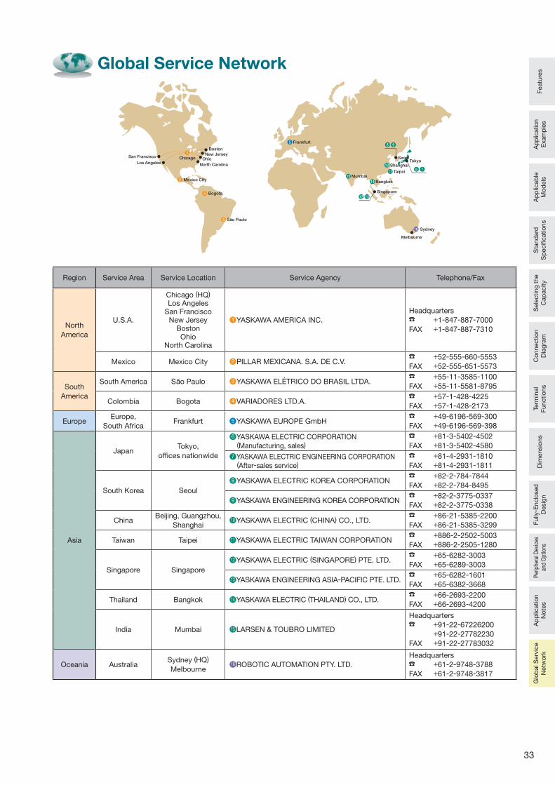
33
Featu
res
Ap
plic
ation
Exam
ple
sA
pp
licab
le
Mo
dels
Sta
nd
ard
S
pecifi c
atio
ns
Sele
cting
the
Cap
acity
Co
nnectio
n
Dia
gra
mTe
rmin
al
Functio
ns
Dim
ensio
ns
Fully
- Enclo
sed
D
esig
nP
erip
hera
l Dev
ices
an
d O
ptio
nsA
pp
licatio
n
No
tes
Glo
bal S
erv
ice
Netw
ork
Global Service Network
Region Service Area Service Location Service Agency Telephone/Fax
North
America
U.S.A.
Chicago (HQ)
Los AngelesSan Francisco
New JerseyBostonOhio
North Carolina
●1 YASKAWA AMERICA INC.
Headquarters
+1-847-887-7000
FAX +1-847-887-7310
Mexico Mexico City ●2 PILLAR MEXICANA. S.A. DE C.V. +52-555-660-5553
FAX +52-555-651-5573
South
America
South America Sao Paulo ●3 YASKAWA ELÉTRICO DO BRASIL LTDA. +55-11-3585-1100
FAX +55-11-5581-8795
Colombia Bogota ●4 VARIADORES LTD.A. +57-1-428-4225
FAX +57-1-428-2173
EuropeEurope,
South AfricaFrankfurt ●5 YASKAWA EUROPE GmbH
+49-6196-569-300
FAX +49-6196-569-398
Asia
JapanTokyo,
offi ces nationwide
●6 YASKAWA ELECTRIC CORPORATION
(Manufacturing, sales) +81-3-5402-4502
FAX +81-3-5402-4580
●7 YASKAWA ELECTRIC ENGINEERING CORPORATION
(After-sales service) +81-4-2931-1810
FAX +81-4-2931-1811
South Korea Seoul
●8 YASKAWA ELECTRIC KOREA CORPORATION +82-2-784-7844
FAX +82-2-784-8495
●9 YASKAWA ENGINEERING KOREA CORPORATION +82-2-3775-0337
FAX +82-2-3775-0338
ChinaBeijing, Guangzhou,
Shanghai●10 YASKAWA ELECTRIC (CHINA) CO., LTD.
+86-21-5385-2200
FAX +86-21-5385-3299
Taiwan Taipei ●11 YASKAWA ELECTRIC TAIWAN CORPORATION +886-2-2502-5003
FAX +886-2-2505-1280
Singapore Singapore
●12 YASKAWA ELECTRIC (SINGAPORE) PTE. LTD. +65-6282-3003
FAX +65-6289-3003
●13 YASKAWA ENGINEERING ASIA-PACIFIC PTE. LTD. +65-6282-1601
FAX +65-6382-3668
Thailand Bangkok ●14 YASKAWA ELECTRIC (THAILAND) CO., LTD. +66-2693-2200
FAX +66-2693-4200
India Mumbai ●15 LARSEN & TOUBRO LIMITED
Headquarters
+91-22-67226200
+91-22-27782230
FAX +91-22-27783032
Oceania AustraliaSydney (HQ)
Melbourne●16 ROBOTIC AUTOMATION PTY. LTD.
Headquarters
+61-2-9748-3788
FAX +61-2-9748-3817
16
ChicagoSan Francisco
Boston
Frankfurt
Mumbai
Singapore
Bangkok
SeoulTokyo
Shanghai
Taipei
Sydney
Melbourne
North Carolina
Mexico City
Bogota
Sao Paulo
New JerseyOhio
Los Angeles
1
4
3
58
10
11
14
15
12 13
9
2
6 7
High-Power Factor Converter with Power Regeneration (K5=0)YASKAWA Energy-Saving Unit
D1000200 V Class, 30 to 130 kW400 V Class, 90 to 370 kW
Certi�ed forISO9001 andISO14001
JQA-EM0498JQA-0422
In the event that the end user of this product is to be the military and said product is to be employed in any weapons systems or the manufacture thereof, the export will fall under the relevant regulations as stipulated in the Foreign Exchange and Foreign Trade Regulations. Therefore, be sure to follow all procedures and submit all relevant documentation according to any and all rules, regulations and laws that may apply.
Speci�cations are subject to change without notice for ongoing product modi�cations and improvements.
© 2013 YASKAWA ELECTRIC CORPORATION. All rights reserved.
LITERATURE NO. KAEP C710656 03A
12-8-11Published in Japan February 2013 13-1
DRIVE CENTER (INVERTER PLANT)2-13-1, Nishimiyaichi, Yukuhashi, Fukuoka, 824-8511, JapanPhone: 81-930-25-3844 Fax: 81-930-25-4369http://www.yaskawa.co.jp
YASKAWA ELECTRIC CORPORATIONNew Pier Takeshiba South Tower, 1-16-1, Kaigan, Minatoku, Tokyo, 105-6891, JapanPhone: 81-3-5402-4502 Fax: 81-3-5402-4580http://www.yaskawa.co.jp
YASKAWA AMERICA, INC.2121 Norman Drive South, Waukegan, IL 60085, U.S.A.Phone: (800) YASKAWA (927-5292) or 1-847-887-7000 Fax: 1-847-887-7310http://www.yaskawa.com
YASKAWA ELETRICO DO BRASIL LTDA.Avenda Fagundes Filho, 620 Bairro Saude, Sao Paulo, SP04304-000, BrazilPhone: 55-11-3585-1100 Fax: 55-11-5581-8795http://www.yaskawa.com.br
YASKAWA EUROPE GmbHHauptstrasse 185, 65760 Eschborn, GermanyPhone: 49-6196-569-300 Fax: 49-6196-569-398http://www.yaskawa.eu.com
YASKAWA ELECTRIC UK LTD.1 Hunt Hill Orchardton Woods, Cumbernauld, G68 9LF, United KingdomPhone: 44-1236-735000 Fax: 44-1236-458182http://www.yaskawa.co.uk
YASKAWA ELECTRIC KOREA CORPORATION9F, Kyobo Securities Bldg., 26-4, Yeouido-dong, Yeongdeungpo-gu, Seoul, 150-737, KoreaPhone: 82-2-784-7844 Fax: 82-2-784-8495http://www.yaskawa.co.kr
YASKAWA ELECTRIC (SINGAPORE) PTE. LTD.151 Lorong Chuan, #04-01, New Tech Park, 556741, SingaporePhone: 65-6282-3003 Fax: 65-6289-3003http://www.yaskawa.com.sg
YASKAWA ELECTRIC (CHINA) CO., LTD.12F, Carlton Bldg., No.21 HuangHe Road, HuangPu District, Shanghai 200003, ChinaPhone: 86-21-5385-2200 Fax: 86-21-5385-3299http://www.yaskawa.com.cn
YASKAWA ELECTRIC (CHINA) CO., LTD. BEIJING OFFICERoom 1011, Tower W3 Oriental Plaza, No.1 East Chang An Ave.,Dong Cheng District, Beijing, 100738, ChinaPhone: 86-10-8518-4086 Fax: 86-10-8518-4082
YASKAWA ELECTRIC TAIWAN CORPORATION9F, 16, Nanking E. Rd., Sec. 3, Taipei, 104, TaiwanPhone: 886-2-2502-5003 Fax: 886-2-2505-1280
YASKAWA ELECTRIC INDIA PRIVATE LIMITED#17/A Electronics City, Hosur Road Bangalore 560 100 (Karnataka), IndiaPhone: 91-80-4244-1900 Fax: 91-80-4244-1901http://www.yaskawaindia.in
YASKAWA ELECTRIC CORPORATION
D1000
0 -1