A Review in Fault Diagnosis and Health Assessment ... - MDPI
19
applied sciences Review A Review in Fault Diagnosis and Health Assessment for Railway Traction Drives Fernando Garramiola * , Javier Poza, Patxi Madina, Jon del Olmo and Gaizka Almandoz Faculty of Engineering, Mondragon Unibertsitatea, 20500 Arrasate-Mondragón, Spain; [email protected] (J.P.); [email protected] (P.M.); [email protected] (J.d.O.); [email protected] (G.A.) * Correspondence: [email protected]; Tel.: +34-943-794-700 Received: 16 November 2018; Accepted: 29 November 2018; Published: 3 December 2018 Abstract: During the last decade, due to the increasing importance of reliability and availability, railway industry is making greater use of fault diagnosis approaches for early fault detection, as well as Condition-based maintenance frameworks. Due to the influence of traction drive in the railway system availability, several research works have been focused on Fault Diagnosis for Railway traction drives. Fault diagnosis approaches have been applied to electric machines, sensors and power electronics. Furthermore, Condition-based maintenance framework seems to reduce corrective and Time-based maintenance works in Railway Systems. However, there is not any publication that summarizes all the research works carried out in Fault diagnosis and Condition-based Maintenance frameworks for Railway Traction Drives. Thus, this review presents the development of Health Assessment and Fault Diagnosis in Railway Traction Drives during the last decade. Keywords: Fault Diagnosis; Health-Assessment; Condition-based maintenance; railway traction drives 1. Introduction In the last decade, due to the increasing importance of availability in Railway systems, early fault diagnosis and Condition-based maintenance (CBM) have become key points for Railway industry. CBM is based on system health monitoring for decision-making [1]. An easy way to formalize a CBM framework is using the standard ISO 13374 [2], in which the CBM tasks are divided into six different levels. The ideal maintenance strategy should be able to act once a fault is detected and before the failure occurs. Thus, cost-effectiveness maintenance decision is made without worsening the availability of the system. Maintenance decision-making can be done based on diagnosis or prognosis. Diagnosis aims to detect and isolate faults, whereas prognosis estimates the future state of a component. Furthermore, other solutions have arisen, as Prognosis and Health Management (PHM), in order to predict and protect the systems based on estimation of time to failure [3]. A review of prognosis methods is presented in [4], classifying the methods depending on the computational resources and historical data quantity needed. CBM requires fault diagnosis for Health Assessment (HA). Fault Detection and Isolation (FDI) approaches detect and located the fault, whereas Fault Detection and Diagnosis (FDD) approaches provide the fault severity too. In case of complex systems and multivariate analysis, FDI approaches can be mainly classified as Model-based and Data-driven. A comparison of different Data-driven approaches, such as Principal Component Analysis (PCA) and Partial Least Squares (PLS), is given in [5]. Model–based approaches require a physical knowledge of system, whereas data-driven approaches need a large quantity of data. Model-based approaches require the development of an analytical model, that simulates the system behaviour, in order to calculate the difference between the real system and the analytical model output, this difference is called residual. This is the signal used Appl. Sci. 2018, 8, 2475; doi:10.3390/app8122475 www.mdpi.com/journal/applsci
-
Upload
khangminh22 -
Category
Documents
-
view
0 -
download
0
Transcript of A Review in Fault Diagnosis and Health Assessment ... - MDPI
applied sciences
Review
A Review in Fault Diagnosis and Health Assessmentfor Railway Traction Drives
Fernando Garramiola * , Javier Poza, Patxi Madina, Jon del Olmo and Gaizka Almandoz
Faculty of Engineering, Mondragon Unibertsitatea, 20500 Arrasate-Mondragón, Spain;[email protected] (J.P.); [email protected] (P.M.); [email protected] (J.d.O.);[email protected] (G.A.)* Correspondence: [email protected]; Tel.: +34-943-794-700
Received: 16 November 2018; Accepted: 29 November 2018; Published: 3 December 2018 �����������������
Abstract: During the last decade, due to the increasing importance of reliability and availability,railway industry is making greater use of fault diagnosis approaches for early fault detection, aswell as Condition-based maintenance frameworks. Due to the influence of traction drive in therailway system availability, several research works have been focused on Fault Diagnosis for Railwaytraction drives. Fault diagnosis approaches have been applied to electric machines, sensors andpower electronics. Furthermore, Condition-based maintenance framework seems to reduce correctiveand Time-based maintenance works in Railway Systems. However, there is not any publication thatsummarizes all the research works carried out in Fault diagnosis and Condition-based Maintenanceframeworks for Railway Traction Drives. Thus, this review presents the development of HealthAssessment and Fault Diagnosis in Railway Traction Drives during the last decade.
Keywords: Fault Diagnosis; Health-Assessment; Condition-based maintenance; railway traction drives
1. Introduction
In the last decade, due to the increasing importance of availability in Railway systems, early faultdiagnosis and Condition-based maintenance (CBM) have become key points for Railway industry.CBM is based on system health monitoring for decision-making [1]. An easy way to formalize aCBM framework is using the standard ISO 13374 [2], in which the CBM tasks are divided into sixdifferent levels. The ideal maintenance strategy should be able to act once a fault is detected andbefore the failure occurs. Thus, cost-effectiveness maintenance decision is made without worsening theavailability of the system. Maintenance decision-making can be done based on diagnosis or prognosis.Diagnosis aims to detect and isolate faults, whereas prognosis estimates the future state of a component.Furthermore, other solutions have arisen, as Prognosis and Health Management (PHM), in order topredict and protect the systems based on estimation of time to failure [3]. A review of prognosismethods is presented in [4], classifying the methods depending on the computational resources andhistorical data quantity needed.
CBM requires fault diagnosis for Health Assessment (HA). Fault Detection and Isolation (FDI)approaches detect and located the fault, whereas Fault Detection and Diagnosis (FDD) approachesprovide the fault severity too. In case of complex systems and multivariate analysis, FDI approachescan be mainly classified as Model-based and Data-driven. A comparison of different Data-drivenapproaches, such as Principal Component Analysis (PCA) and Partial Least Squares (PLS), is givenin [5]. Model–based approaches require a physical knowledge of system, whereas data-drivenapproaches need a large quantity of data. Model-based approaches require the development ofan analytical model, that simulates the system behaviour, in order to calculate the difference betweenthe real system and the analytical model output, this difference is called residual. This is the signal used
Appl. Sci. 2018, 8, 2475; doi:10.3390/app8122475 www.mdpi.com/journal/applsci
Appl. Sci. 2018, 8, 2475 2 of 19
for fault detection, as it is shown in Figure 1. Analytical models are mainly developed by structuralapproaches [6], based on consistency relation and observer-based approaches [7]. Residual evaluationis done using norms or statistical methods [8]. Some statistical methods are Hypothesis tests orLikelihood ratio (LR). Likelihood ratio is given by Equation (1), being p the probability density for anormal distribution N
(µ, σ2), where µ is the mean value and σ2 is the variance. Probability density is
given by Equation (2) to evaluate the residual r. Thus, p(r) gives the probability of a given sample ofthe residual to be within the normal distribution N
(µ, σ2). On the other hand, LR shows which of the
compared probability densities is more probable. For example, if a faulty case given by p1 is comparedto a fault-free case given by p0, as it is shown in Equation (1), in case that the LR(r) > 0 faulty case isaccepted, as p1 is more probable than p0, otherwise it is a fault-free case.
LR(r) = lnp1(r)p0 (r)
, (1)
being p1 and p0 the probability density of the residual for two normal distributions, for example, faultyand a fault-free cases.
p(r) =1
σ√
2πe−
(r−µ)2
2σ2 , (2)
being µ and σ2 the mean value and variance of the normal distribution to which the residual willbe compared.
Appl. Sci. 2018, 8, x FOR PEER REVIEW 2 of 19
analytical model, that simulates the system behaviour, in order to calculate the difference between the real system and the analytical model output, this difference is called residual. This is the signal used for fault detection, as it is shown in Figure 1. Analytical models are mainly developed by structural approaches [6], based on consistency relation and observer-based approaches [7]. Residual evaluation is done using norms or statistical methods [8]. Some statistical methods are Hypothesis tests or Likelihood ratio (LR). Likelihood ratio is given by Equation (1), being 𝑝 the probability density for a normal distribution Ν(𝜇, 𝜎 ) , where 𝜇 is the mean value and 𝜎 is the variance. Probability density is given by Equation (2) to evaluate the residual 𝑟 . Thus, 𝑝(𝑟) gives the probability of a given sample of the residual to be within the normal distribution Ν(𝜇, 𝜎 ). On the other hand, LR shows which of the compared probability densities is more probable. For example, if a faulty case given by 𝑝 is compared to a fault-free case given by 𝑝 , as it is shown in Equation (1), in case that the 𝐿𝑅(𝑟) > 0 faulty case is accepted, as 𝑝 is more probable than 𝑝 , otherwise it is a fault-free case. 𝐿𝑅(𝑟) = ln 𝑝 (𝑟)𝑝 (𝑟) , (1)
being 𝑝 and 𝑝 the probability density of the residual for two normal distributions, for example, faulty and a fault-free cases. 𝑝(𝑟 ) = 1𝜎√2𝜋 𝑒 ( ) , (2)
being 𝜇 and 𝜎 the mean value and variance of the normal distribution to which the residual will be compared.
System
Analytical model
Residual generation Residual evaluation
Faultdecision
Outputs
Residual
Threshold
+
-
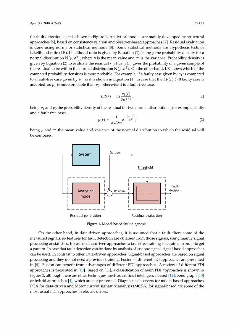
Figure 1. Model-based fault diagnosis.
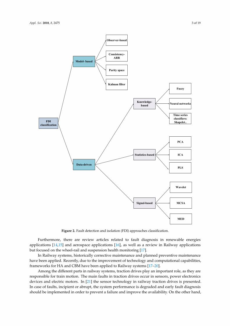
On the other hand, in data-driven approaches, it is assumed that a fault alters some of the measured signals, so features for fault detection are obtained from those signals, using mainly signal processing or statistics. In case of data-driven approaches, a fault-free training is required in order to get a pattern. In case that fault detection can be done by analysis of just one signal, signal-based approaches can be used. In contrast to other Data-driven approaches, Signal-based approaches are based on signal processing and they do not need a previous training. Fusion of different FDI approaches are presented in [9]. Fusion can benefit from advantages of different FDI approaches. A review of different FDI approaches is presented in [10]. Based on [11], a classification of main FDI approaches is shown in Figure 2, although there are other techniques, such as artificial intelligence based [12], bond graph [13] or hybrid approaches [4], which are not presented. Diagnostic observers for model-based approaches, PCA for data-driven and Motor current signature analysis (MCSA) for signal-based are some of the most usual FDI approaches in electric drives.
Furthermore, there are review articles related to fault diagnosis in renewable energies applications [14,15] and aerospace applications [16], as well as a review in Railway applications but focused on the wheel-rail and suspension health monitoring [17].
Figure 1. Model-based fault diagnosis.
On the other hand, in data-driven approaches, it is assumed that a fault alters some of themeasured signals, so features for fault detection are obtained from those signals, using mainly signalprocessing or statistics. In case of data-driven approaches, a fault-free training is required in order to geta pattern. In case that fault detection can be done by analysis of just one signal, signal-based approachescan be used. In contrast to other Data-driven approaches, Signal-based approaches are based on signalprocessing and they do not need a previous training. Fusion of different FDI approaches are presentedin [9]. Fusion can benefit from advantages of different FDI approaches. A review of different FDIapproaches is presented in [10]. Based on [11], a classification of main FDI approaches is shown inFigure 2, although there are other techniques, such as artificial intelligence based [12], bond graph [13]or hybrid approaches [4], which are not presented. Diagnostic observers for model-based approaches,PCA for data-driven and Motor current signature analysis (MCSA) for signal-based are some of themost usual FDI approaches in electric drives.
Appl. Sci. 2018, 8, 2475 3 of 19
Appl. Sci. 2018, 8, x FOR PEER REVIEW 3 of 19
In Railway systems, historically corrective maintenance and planned preventive maintenance have been applied. Recently, due to the improvement of technology and computational capabilities, frameworks for HA and CBM have been applied to Railway systems [17–20].
Among the different parts in railway systems, traction drives play an important role, as they are responsible for train motion. The main faults in traction drives occur in sensors, power electronics devices and electric motors. In [21] the sensor technology in railway traction drives is presented. In case of faults, incipient or abrupt, the system performance is degraded and early fault diagnosis should be implemented in order to prevent a failure and improve the availability. On the other hand, in case of hard faults, mainly in sensors that take part in the control strategy, the system leaves the safety zone and protections act. Thus, it could be hard to avoid the failure and there could be a loss of availability, unless a fault tolerant control (FTC) is implemented. A review of FTC is presented in [22]. Several publications related to the application of FDI to electric traction drives are presented in the literature [23]. The research works are focused on sensors [24–26], power electronics devices [15,27] and electric motors [28–30].
FDI classification
Model- based
Observer-based
Consistency- ARR
Parity space
Kalman filter
Knowledge-based
Statistics-based
Signal-based
Wavelet
MCSA
PCA
ICA
PLS
Fuzzy
Neural networks
MED
Time series classifiers: Shapelet..
Data-driven
Figure 2. Fault detection and isolation (FDI) approaches classification. Figure 2. Fault detection and isolation (FDI) approaches classification.
Furthermore, there are review articles related to fault diagnosis in renewable energiesapplications [14,15] and aerospace applications [16], as well as a review in Railway applicationsbut focused on the wheel-rail and suspension health monitoring [17].
In Railway systems, historically corrective maintenance and planned preventive maintenancehave been applied. Recently, due to the improvement of technology and computational capabilities,frameworks for HA and CBM have been applied to Railway systems [17–20].
Among the different parts in railway systems, traction drives play an important role, as they areresponsible for train motion. The main faults in traction drives occur in sensors, power electronicsdevices and electric motors. In [21] the sensor technology in railway traction drives is presented.In case of faults, incipient or abrupt, the system performance is degraded and early fault diagnosisshould be implemented in order to prevent a failure and improve the availability. On the other hand,
Appl. Sci. 2018, 8, 2475 4 of 19
in case of hard faults, mainly in sensors that take part in the control strategy, the system leaves thesafety zone and protections act. Thus, it could be hard to avoid the failure and there could be a loss ofavailability, unless a fault tolerant control (FTC) is implemented. A review of FTC is presented in [22].Several publications related to the application of FDI to electric traction drives are presented in theliterature [23]. The research works are focused on sensors [24–26], power electronics devices [15,27]and electric motors [28–30].
Furthermore, although during the last decade several publications related to fault diagnosis andhealth assessment in Railway traction drives have been published [25,31–33], there is not a review,which summarizes all the research work done in Railway traction drives. Previous review works arefocused on sensors more than in fault diagnosis [21] or on fault diagnosis in railway traction powersupply [18].
The objective of this article is to present the latest research works in fault diagnosis and healthassessment in Railway traction drives, as an essential asset for its integration in a CBM system. Scopusand Web of Science databases have been used, following PRISMA guidelines, in order to gather therelevant research works. First, documents are selected in case of finding one of the following keywords:“fault,” “monitoring” or “maintenance” on the author keywords, abstract or title. In addition to thesekeywords, search was limited to documents where “railway” and “traction” keywords appear on thetitle. Then, the search was refined to articles and conference proceedings since 2005, in the field ofengineering, computing and decision sciences. 80 documents in Scopus and 62 in Web of Science werelisted and both lists were compared to avoid duplicities. Finally, the documents were analysed in orderto select the ones related to health assessment and fault diagnosis in Railway Traction drives.
The article has the following structure: Section 2 summarizes the research works in Healthassessment and CBM in Railway traction drives. Section 3 presents different FDI approaches appliedto Railway systems. Section 4 presents the state of the art of fault diagnosis in Railway Traction Drives.Finally the discussions and conclusions are given.
2. Condition-Based Maintenance in Railway Systems
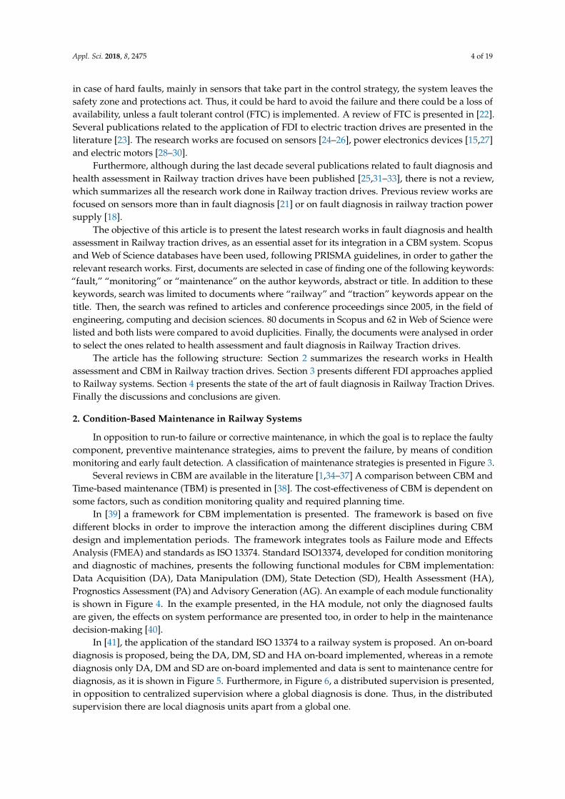
In opposition to run-to failure or corrective maintenance, in which the goal is to replace the faultycomponent, preventive maintenance strategies, aims to prevent the failure, by means of conditionmonitoring and early fault detection. A classification of maintenance strategies is presented in Figure 3.
Several reviews in CBM are available in the literature [1,34–37] A comparison between CBM andTime-based maintenance (TBM) is presented in [38]. The cost-effectiveness of CBM is dependent onsome factors, such as condition monitoring quality and required planning time.
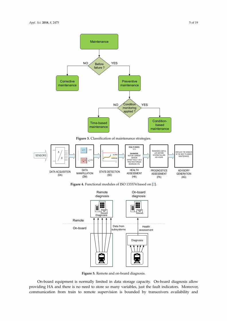
In [39] a framework for CBM implementation is presented. The framework is based on fivedifferent blocks in order to improve the interaction among the different disciplines during CBMdesign and implementation periods. The framework integrates tools as Failure mode and EffectsAnalysis (FMEA) and standards as ISO 13374. Standard ISO13374, developed for condition monitoringand diagnostic of machines, presents the following functional modules for CBM implementation:Data Acquisition (DA), Data Manipulation (DM), State Detection (SD), Health Assessment (HA),Prognostics Assessment (PA) and Advisory Generation (AG). An example of each module functionalityis shown in Figure 4. In the example presented, in the HA module, not only the diagnosed faultsare given, the effects on system performance are presented too, in order to help in the maintenancedecision-making [40].
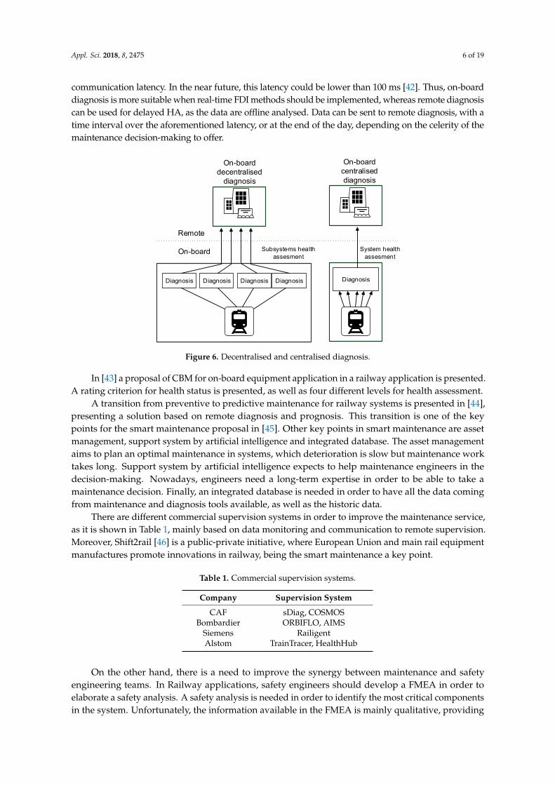
In [41], the application of the standard ISO 13374 to a railway system is proposed. An on-boarddiagnosis is proposed, being the DA, DM, SD and HA on-board implemented, whereas in a remotediagnosis only DA, DM and SD are on-board implemented and data is sent to maintenance centre fordiagnosis, as it is shown in Figure 5. Furthermore, in Figure 6, a distributed supervision is presented,in opposition to centralized supervision where a global diagnosis is done. Thus, in the distributedsupervision there are local diagnosis units apart from a global one.
Appl. Sci. 2018, 8, 2475 5 of 19
Appl. Sci. 2018, 8, x FOR PEER REVIEW 4 of 19
Furthermore, although during the last decade several publications related to fault diagnosis and health assessment in Railway traction drives have been published [25,31–33], there is not a review, which summarizes all the research work done in Railway traction drives. Previous review works are focused on sensors more than in fault diagnosis [21] or on fault diagnosis in railway traction power supply [18].
The objective of this article is to present the latest research works in fault diagnosis and health assessment in Railway traction drives, as an essential asset for its integration in a CBM system. Scopus and Web of Science databases have been used, following PRISMA guidelines, in order to gather the relevant research works. First, documents are selected in case of finding one of the following keywords: “fault,” “monitoring” or “maintenance” on the author keywords, abstract or title. In addition to these keywords, search was limited to documents where “railway” and “traction” keywords appear on the title. Then, the search was refined to articles and conference proceedings since 2005, in the field of engineering, computing and decision sciences. 80 documents in Scopus and 62 in Web of Science were listed and both lists were compared to avoid duplicities. Finally, the documents were analysed in order to select the ones related to health assessment and fault diagnosis in Railway Traction drives.
The article has the following structure: Section 2 summarizes the research works in Health assessment and CBM in Railway traction drives. Section 3 presents different FDI approaches applied to Railway systems. Section 4 presents the state of the art of fault diagnosis in Railway Traction Drives. Finally the discussions and conclusions are given.
2. Condition-Based Maintenance in Railway Systems
In opposition to run-to failure or corrective maintenance, in which the goal is to replace the faulty component, preventive maintenance strategies, aims to prevent the failure, by means of condition monitoring and early fault detection. A classification of maintenance strategies is presented in Figure 3.
Maintenance
Before failure ?
Correctivemaintenance
Preventive maintenance
Condition monitoringapplied ?
Time-basedmaintenance
Condition-based
maintenance
NO YES
YESNO
Figure 3. Classification of maintenance strategies.
Several reviews in CBM are available in the literature [1,34–37] A comparison between CBM and Time-based maintenance (TBM) is presented in [38]. The cost-effectiveness of CBM is dependent on some factors, such as condition monitoring quality and required planning time.
Figure 3. Classification of maintenance strategies.
Appl. Sci. 2018, 8, x FOR PEER REVIEW 5 of 19
In [39] a framework for CBM implementation is presented. The framework is based on five different blocks in order to improve the interaction among the different disciplines during CBM design and implementation periods. The framework integrates tools as Failure mode and Effects Analysis (FMEA) and standards as ISO 13374. Standard ISO13374, developed for condition monitoring and diagnostic of machines, presents the following functional modules for CBM implementation: Data Acquisition (DA), Data Manipulation (DM), State Detection (SD), Health Assessment (HA), Prognostics Assessment (PA) and Advisory Generation (AG). An example of each module functionality is shown in Figure 4. In the example presented, in the HA module, not only the diagnosed faults are given, the effects on system performance are presented too, in order to help in the maintenance decision-making [40].
SENSORS
DATA ACQUISITION(DA)
DATA MANIPULATION
(DM)
STATE DETECTION(SD)
HEALTH ASSESSMENT
(HA)
PROGNOSTICS ASSESSMENT
(PA)
ADVISORY GENERATION
(AG)
WARNING
ALARM
HEALTH INDEX: 5/10
DIAGNOSIS:MOTOR CURRENT
SENSOR OFFSET FAULT +40 ATRACTION TORQUE
DECREASE 10%
REMAINING USEFUL LIFE BEFORE
SYSTEM FAILURE:420 HOURS
t
r REPLACE THE SENSOR IN THE NEXT PLANNED
MAINTENANCE
A
D
Figure 4. Functional modules of ISO 133374 based on [2].
In [41], the application of the standard ISO 13374 to a railway system is proposed. An on-board diagnosis is proposed, being the DA, DM, SD and HA on-board implemented, whereas in a remote diagnosis only DA, DM and SD are on-board implemented and data is sent to maintenance centre for diagnosis, as it is shown in Figure 5. Furthermore, in Figure 6, a distributed supervision is presented, in opposition to centralized supervision where a global diagnosis is done. Thus, in the distributed supervision there are local diagnosis units apart from a global one.
On-board
RemoteDiagnosis
Diagnosis
Remotediagnosis
On-boarddiagnosis
Health assessment
Data from subsystems
Figure 5. Remote and on-board diagnosis.
On-board equipment is normally limited in data storage capacity. On-board diagnosis allow providing HA and there is no need to store so many variables, just the fault indicators. Moreover, communication from train to remote supervision is bounded by transceivers availability and communication latency. In the near future, this latency could be lower than 100 ms [42]. Thus, on-board diagnosis is more suitable when real-time FDI methods should be implemented, whereas remote diagnosis can be used for delayed HA, as the data are offline analysed. Data can be sent to
Figure 4. Functional modules of ISO 133374 based on [2].
Appl. Sci. 2018, 8, x FOR PEER REVIEW 5 of 19
In [39] a framework for CBM implementation is presented. The framework is based on five different blocks in order to improve the interaction among the different disciplines during CBM design and implementation periods. The framework integrates tools as Failure mode and Effects Analysis (FMEA) and standards as ISO 13374. Standard ISO13374, developed for condition monitoring and diagnostic of machines, presents the following functional modules for CBM implementation: Data Acquisition (DA), Data Manipulation (DM), State Detection (SD), Health Assessment (HA), Prognostics Assessment (PA) and Advisory Generation (AG). An example of each module functionality is shown in Figure 4. In the example presented, in the HA module, not only the diagnosed faults are given, the effects on system performance are presented too, in order to help in the maintenance decision-making [40].
SENSORS
DATA ACQUISITION(DA)
DATA MANIPULATION
(DM)
STATE DETECTION(SD)
HEALTH ASSESSMENT
(HA)
PROGNOSTICS ASSESSMENT
(PA)
ADVISORY GENERATION
(AG)
WARNING
ALARM
HEALTH INDEX: 5/10
DIAGNOSIS:MOTOR CURRENT
SENSOR OFFSET FAULT +40 ATRACTION TORQUE
DECREASE 10%
REMAINING USEFUL LIFE BEFORE
SYSTEM FAILURE:420 HOURS
t
r REPLACE THE SENSOR IN THE NEXT PLANNED
MAINTENANCE
A
D
Figure 4. Functional modules of ISO 133374 based on [2].
In [41], the application of the standard ISO 13374 to a railway system is proposed. An on-board diagnosis is proposed, being the DA, DM, SD and HA on-board implemented, whereas in a remote diagnosis only DA, DM and SD are on-board implemented and data is sent to maintenance centre for diagnosis, as it is shown in Figure 5. Furthermore, in Figure 6, a distributed supervision is presented, in opposition to centralized supervision where a global diagnosis is done. Thus, in the distributed supervision there are local diagnosis units apart from a global one.
On-board
RemoteDiagnosis
Diagnosis
Remotediagnosis
On-boarddiagnosis
Health assessment
Data from subsystems
Figure 5. Remote and on-board diagnosis.
On-board equipment is normally limited in data storage capacity. On-board diagnosis allow providing HA and there is no need to store so many variables, just the fault indicators. Moreover, communication from train to remote supervision is bounded by transceivers availability and communication latency. In the near future, this latency could be lower than 100 ms [42]. Thus, on-board diagnosis is more suitable when real-time FDI methods should be implemented, whereas remote diagnosis can be used for delayed HA, as the data are offline analysed. Data can be sent to
Figure 5. Remote and on-board diagnosis.
On-board equipment is normally limited in data storage capacity. On-board diagnosis allowproviding HA and there is no need to store so many variables, just the fault indicators. Moreover,communication from train to remote supervision is bounded by transceivers availability and
Appl. Sci. 2018, 8, 2475 6 of 19
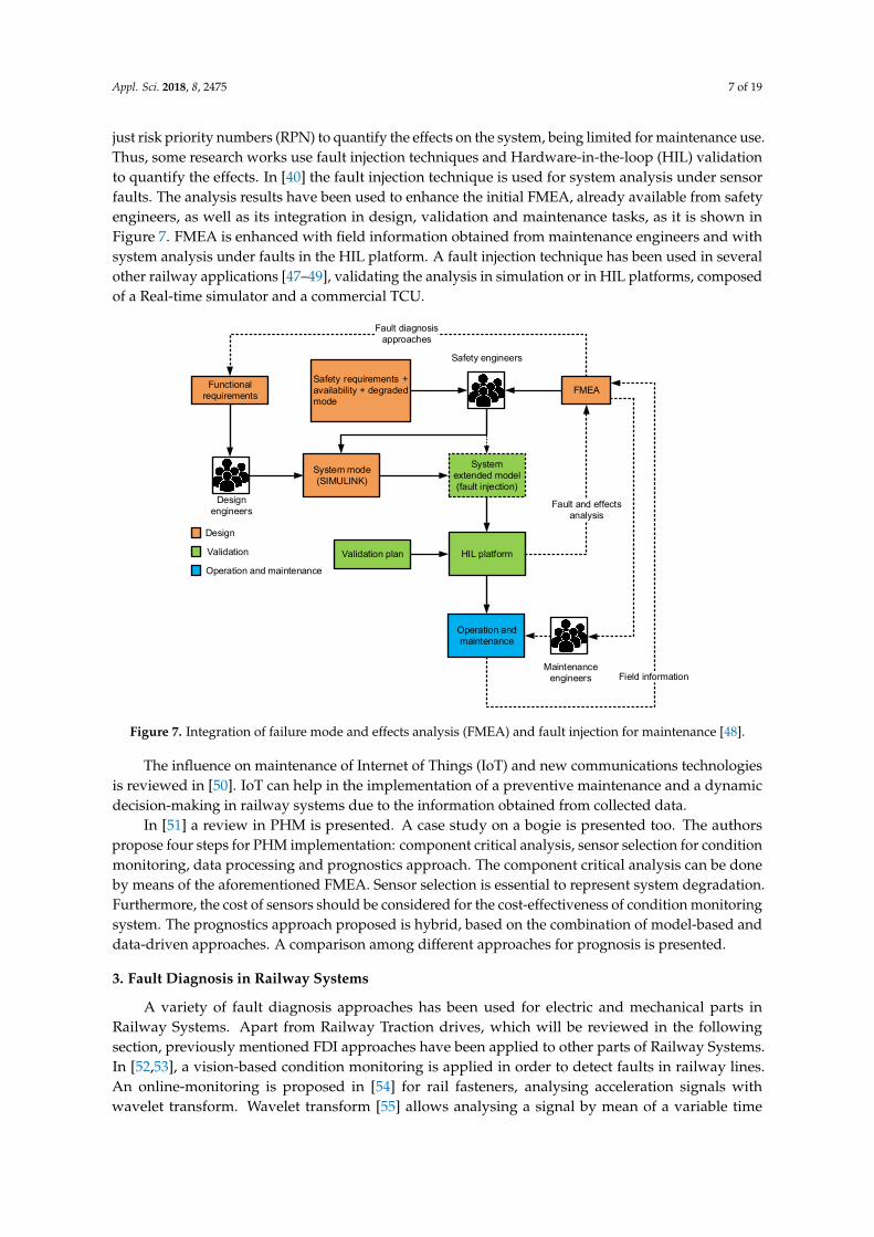
communication latency. In the near future, this latency could be lower than 100 ms [42]. Thus, on-boarddiagnosis is more suitable when real-time FDI methods should be implemented, whereas remote diagnosiscan be used for delayed HA, as the data are offline analysed. Data can be sent to remote diagnosis, with atime interval over the aforementioned latency, or at the end of the day, depending on the celerity of themaintenance decision-making to offer.
Appl. Sci. 2018, 8, x FOR PEER REVIEW 6 of 19
remote diagnosis, with a time interval over the aforementioned latency, or at the end of the day, depending on the celerity of the maintenance decision-making to offer.
On-board
Remote
Diagnosis
On-boarddecentralised
diagnosis
On-board centraliseddiagnosis
Subsystems health assesment
Diagnosis Diagnosis Diagnosis Diagnosis
System health assesment
Figure 6. Decentralised and centralised diagnosis.
In [43] a proposal of CBM for on-board equipment application in a railway application is presented. A rating criterion for health status is presented, as well as four different levels for health assessment.
A transition from preventive to predictive maintenance for railway systems is presented in [44], presenting a solution based on remote diagnosis and prognosis. This transition is one of the key points for the smart maintenance proposal in [45]. Other key points in smart maintenance are asset management, support system by artificial intelligence and integrated database. The asset management aims to plan an optimal maintenance in systems, which deterioration is slow but maintenance work takes long. Support system by artificial intelligence expects to help maintenance engineers in the decision-making. Nowadays, engineers need a long-term expertise in order to be able to take a maintenance decision. Finally, an integrated database is needed in order to have all the data coming from maintenance and diagnosis tools available, as well as the historic data.
There are different commercial supervision systems in order to improve the maintenance service, as it is shown in Table 1, mainly based on data monitoring and communication to remote supervision. Moreover, Shift2rail [46] is a public-private initiative, where European Union and main rail equipment manufactures promote innovations in railway, being the smart maintenance a key point.
Table 1. Commercial supervision systems.
Company Supervision System CAF sDiag, COSMOS
Bombardier ORBIFLO, AIMS Siemens Railigent Alstom TrainTracer, HealthHub
On the other hand, there is a need to improve the synergy between maintenance and safety engineering teams. In Railway applications, safety engineers should develop a FMEA in order to elaborate a safety analysis. A safety analysis is needed in order to identify the most critical components in the system. Unfortunately, the information available in the FMEA is mainly qualitative, providing just risk priority numbers (RPN) to quantify the effects on the system, being limited for maintenance use. Thus, some research works use fault injection techniques and Hardware-
Figure 6. Decentralised and centralised diagnosis.
In [43] a proposal of CBM for on-board equipment application in a railway application is presented.A rating criterion for health status is presented, as well as four different levels for health assessment.
A transition from preventive to predictive maintenance for railway systems is presented in [44],presenting a solution based on remote diagnosis and prognosis. This transition is one of the keypoints for the smart maintenance proposal in [45]. Other key points in smart maintenance are assetmanagement, support system by artificial intelligence and integrated database. The asset managementaims to plan an optimal maintenance in systems, which deterioration is slow but maintenance worktakes long. Support system by artificial intelligence expects to help maintenance engineers in thedecision-making. Nowadays, engineers need a long-term expertise in order to be able to take amaintenance decision. Finally, an integrated database is needed in order to have all the data comingfrom maintenance and diagnosis tools available, as well as the historic data.
There are different commercial supervision systems in order to improve the maintenance service,as it is shown in Table 1, mainly based on data monitoring and communication to remote supervision.Moreover, Shift2rail [46] is a public-private initiative, where European Union and main rail equipmentmanufactures promote innovations in railway, being the smart maintenance a key point.
Table 1. Commercial supervision systems.
Company Supervision System
CAF sDiag, COSMOSBombardier ORBIFLO, AIMS
Siemens RailigentAlstom TrainTracer, HealthHub
On the other hand, there is a need to improve the synergy between maintenance and safetyengineering teams. In Railway applications, safety engineers should develop a FMEA in order toelaborate a safety analysis. A safety analysis is needed in order to identify the most critical componentsin the system. Unfortunately, the information available in the FMEA is mainly qualitative, providing
Appl. Sci. 2018, 8, 2475 7 of 19
just risk priority numbers (RPN) to quantify the effects on the system, being limited for maintenance use.Thus, some research works use fault injection techniques and Hardware-in-the-loop (HIL) validationto quantify the effects. In [40] the fault injection technique is used for system analysis under sensorfaults. The analysis results have been used to enhance the initial FMEA, already available from safetyengineers, as well as its integration in design, validation and maintenance tasks, as it is shown inFigure 7. FMEA is enhanced with field information obtained from maintenance engineers and withsystem analysis under faults in the HIL platform. A fault injection technique has been used in severalother railway applications [47–49], validating the analysis in simulation or in HIL platforms, composedof a Real-time simulator and a commercial TCU.
Appl. Sci. 2018, 8, x FOR PEER REVIEW 7 of 19
in-the-loop (HIL) validation to quantify the effects. In [40] the fault injection technique is used for system analysis under sensor faults. The analysis results have been used to enhance the initial FMEA, already available from safety engineers, as well as its integration in design, validation and maintenance tasks, as it is shown in Figure 7. FMEA is enhanced with field information obtained from maintenance engineers and with system analysis under faults in the HIL platform. A fault injection technique has been used in several other railway applications [47–49], validating the analysis in simulation or in HIL platforms, composed of a Real-time simulator and a commercial TCU.
System mode(SIMULINK)
System extended model (fault injection)
Functional requirements
HIL platform
FMEASafety requirements + availability + degraded mode
Validation plan
Fault and effects analysis
Design engineers
Safety engineers
Fault diagnosis approaches
Operation and maintenance
Maintenance engineers
Design
Validation
Operation and maintenance
Field information
Figure 7. Integration of failure mode and effects analysis (FMEA) and fault injection for maintenance [48].
The influence on maintenance of Internet of Things (IoT) and new communications technologies is reviewed in [50]. IoT can help in the implementation of a preventive maintenance and a dynamic decision-making in railway systems due to the information obtained from collected data.
In [51] a review in PHM is presented. A case study on a bogie is presented too. The authors propose four steps for PHM implementation: component critical analysis, sensor selection for condition monitoring, data processing and prognostics approach. The component critical analysis can be done by means of the aforementioned FMEA. Sensor selection is essential to represent system degradation. Furthermore, the cost of sensors should be considered for the cost-effectiveness of condition monitoring system. The prognostics approach proposed is hybrid, based on the combination of model-based and data-driven approaches. A comparison among different approaches for prognosis is presented.
3. Fault Diagnosis in Railway Systems
A variety of fault diagnosis approaches has been used for electric and mechanical parts in Railway Systems. Apart from Railway Traction drives, which will be reviewed in the following section, previously mentioned FDI approaches have been applied to other parts of Railway Systems. In [52,53], a vision-based condition monitoring is applied in order to detect faults in railway lines. An online-monitoring is proposed in [54] for rail fasteners, analysing acceleration signals with wavelet transform. Wavelet transform [55] allows analysing a signal by mean of a variable time window and different scaling, inversely proportional to frequency, as it is shown in (3) for continuous wavelet transform.
Figure 7. Integration of failure mode and effects analysis (FMEA) and fault injection for maintenance [48].
The influence on maintenance of Internet of Things (IoT) and new communications technologiesis reviewed in [50]. IoT can help in the implementation of a preventive maintenance and a dynamicdecision-making in railway systems due to the information obtained from collected data.
In [51] a review in PHM is presented. A case study on a bogie is presented too. The authorspropose four steps for PHM implementation: component critical analysis, sensor selection for conditionmonitoring, data processing and prognostics approach. The component critical analysis can be doneby means of the aforementioned FMEA. Sensor selection is essential to represent system degradation.Furthermore, the cost of sensors should be considered for the cost-effectiveness of condition monitoringsystem. The prognostics approach proposed is hybrid, based on the combination of model-based anddata-driven approaches. A comparison among different approaches for prognosis is presented.
3. Fault Diagnosis in Railway Systems
A variety of fault diagnosis approaches has been used for electric and mechanical parts inRailway Systems. Apart from Railway Traction drives, which will be reviewed in the followingsection, previously mentioned FDI approaches have been applied to other parts of Railway Systems.In [52,53], a vision-based condition monitoring is applied in order to detect faults in railway lines.An online-monitoring is proposed in [54] for rail fasteners, analysing acceleration signals withwavelet transform. Wavelet transform [55] allows analysing a signal by mean of a variable time
Appl. Sci. 2018, 8, 2475 8 of 19
window and different scaling, inversely proportional to frequency, as it is shown in (3) for continuouswavelet transform.
wt(s, τ) =1√
s
∫ ∞
−∞x(t)Ψ∗
(t− τ
s
)dt, (3)
being Ψ∗( t−τ
s)
the complex conjugate of wavelet basis for the time translation τ and scaling s and x(t)the signal to transform.
One of the applications of wavelet transform is the suppression of the noise in the originalsignal. Based on wavelet transform, Wavelet Packet Transform (WPT) improves the resolution forhigh-frequency region. The signal is decomposed into approximation and detail signals, then the detailsignals are limited to a threshold and finally the signal is reconstructed based on approximation anddetail signals. In case of fault detection applications, a suitable wavelet basis should be chose in orderto classify between fault-free and faulty cases. Wavelet basis could be selected to identify changes inentropy, energy and so forth. In [56] WPT energy is applied to vibrations signals in combination withneural networks, in order to detect faults in the axle of bogies.
Vibration signals are analysed by mean of another signal-based approach, an improved MinimumEntropy Deconvolution (MED) [57], in order to detect faults in bearing. The method presentedimproves the fault diagnosis in case of low signal-to-noise ratio compared to classical MED.
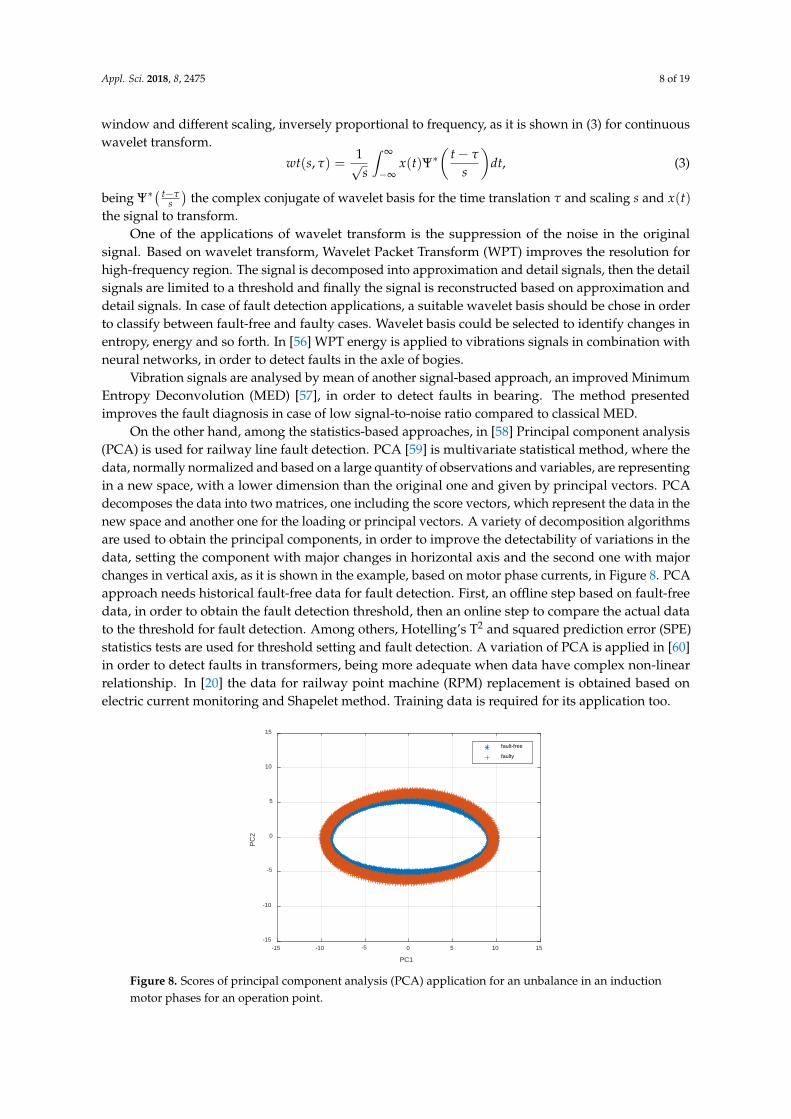
On the other hand, among the statistics-based approaches, in [58] Principal component analysis(PCA) is used for railway line fault detection. PCA [59] is multivariate statistical method, where thedata, normally normalized and based on a large quantity of observations and variables, are representingin a new space, with a lower dimension than the original one and given by principal vectors. PCAdecomposes the data into two matrices, one including the score vectors, which represent the data in thenew space and another one for the loading or principal vectors. A variety of decomposition algorithmsare used to obtain the principal components, in order to improve the detectability of variations in thedata, setting the component with major changes in horizontal axis and the second one with majorchanges in vertical axis, as it is shown in the example, based on motor phase currents, in Figure 8. PCAapproach needs historical fault-free data for fault detection. First, an offline step based on fault-freedata, in order to obtain the fault detection threshold, then an online step to compare the actual datato the threshold for fault detection. Among others, Hotelling’s T2 and squared prediction error (SPE)statistics tests are used for threshold setting and fault detection. A variation of PCA is applied in [60]in order to detect faults in transformers, being more adequate when data have complex non-linearrelationship. In [20] the data for railway point machine (RPM) replacement is obtained based onelectric current monitoring and Shapelet method. Training data is required for its application too.
Appl. Sci. 2018, 8, x FOR PEER REVIEW 8 of 19
𝑤𝑤𝑤𝑤(𝑠𝑠, 𝜏𝜏) =1√𝑠𝑠
� 𝑥𝑥(𝑤𝑤)Ψ∗ �𝑤𝑤 − 𝜏𝜏𝑠𝑠
�𝑑𝑑𝑤𝑤,∞
−∞ (3)
being Ψ∗ �𝑡𝑡−𝜏𝜏𝑠𝑠� the complex conjugate of wavelet basis for the time translation 𝜏𝜏 and scaling 𝑠𝑠 and
𝑥𝑥(𝑤𝑤) the signal to transform. One of the applications of wavelet transform is the suppression of the noise in the original signal.
Based on wavelet transform, Wavelet Packet Transform (WPT) improves the resolution for high-frequency region. The signal is decomposed into approximation and detail signals, then the detail signals are limited to a threshold and finally the signal is reconstructed based on approximation and detail signals. In case of fault detection applications, a suitable wavelet basis should be chose in order to classify between fault-free and faulty cases. Wavelet basis could be selected to identify changes in entropy, energy and so forth. In [56] WPT energy is applied to vibrations signals in combination with neural networks, in order to detect faults in the axle of bogies.
Vibration signals are analysed by mean of another signal-based approach, an improved Minimum Entropy Deconvolution (MED) [57], in order to detect faults in bearing. The method presented improves the fault diagnosis in case of low signal-to-noise ratio compared to classical MED.
On the other hand, among the statistics-based approaches, in [58] Principal component analysis (PCA) is used for railway line fault detection. PCA [59] is multivariate statistical method, where the data, normally normalized and based on a large quantity of observations and variables, are representing in a new space, with a lower dimension than the original one and given by principal vectors. PCA decomposes the data into two matrices, one including the score vectors, which represent the data in the new space and another one for the loading or principal vectors. A variety of decomposition algorithms are used to obtain the principal components, in order to improve the detectability of variations in the data, setting the component with major changes in horizontal axis and the second one with major changes in vertical axis, as it is shown in the example, based on motor phase currents, in Figure 8. PCA approach needs historical fault-free data for fault detection. First, an offline step based on fault-free data, in order to obtain the fault detection threshold, then an online step to compare the actual data to the threshold for fault detection. Among others, Hotelling’s T2 and squared prediction error (SPE) statistics tests are used for threshold setting and fault detection. A variation of PCA is applied in [60] in order to detect faults in transformers, being more adequate when data have complex non-linear relationship. In [20] the data for railway point machine (RPM) replacement is obtained based on electric current monitoring and Shapelet method. Training data is required for its application too.
Figure 8. Scores of principal component analysis (PCA) application for an unbalance in an induction motor phases for an operation point.
-15 -10 -5 0 5 10 15
PC1
-15
-10
-5
0
5
10
15
PC2
fault-free
faulty
Figure 8. Scores of principal component analysis (PCA) application for an unbalance in an inductionmotor phases for an operation point.
Appl. Sci. 2018, 8, 2475 9 of 19
Among the model-based approaches, a consistency-based approach, given analytical redundancyrelations (ARR), is proposed for traction power supply fault detection [61]. An Observer-basedapproach is presented in [62] for sensor fault detection in the suspension system. A hypothesis test isutilized for residual evaluation.
4. Fault Diagnosis in Railway Traction Drives
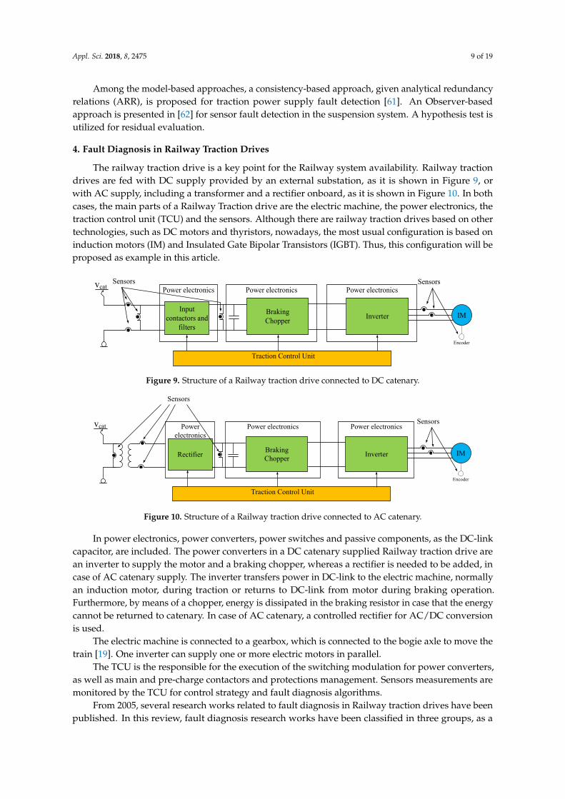
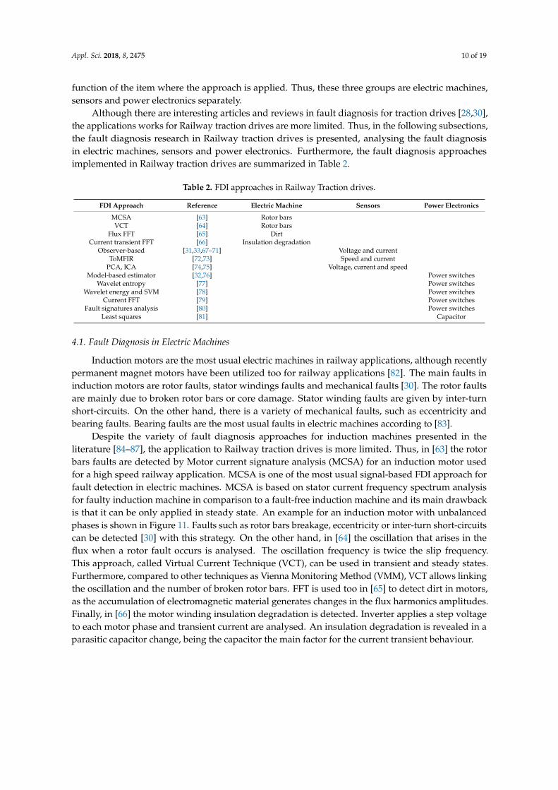
The railway traction drive is a key point for the Railway system availability. Railway tractiondrives are fed with DC supply provided by an external substation, as it is shown in Figure 9, orwith AC supply, including a transformer and a rectifier onboard, as it is shown in Figure 10. In bothcases, the main parts of a Railway Traction drive are the electric machine, the power electronics, thetraction control unit (TCU) and the sensors. Although there are railway traction drives based on othertechnologies, such as DC motors and thyristors, nowadays, the most usual configuration is based oninduction motors (IM) and Insulated Gate Bipolar Transistors (IGBT). Thus, this configuration will beproposed as example in this article.
Appl. Sci. 2018, 8, x FOR PEER REVIEW 9 of 19
Among the model-based approaches, a consistency-based approach, given analytical redundancy relations (ARR), is proposed for traction power supply fault detection [61]. An Observer-based approach is presented in [62] for sensor fault detection in the suspension system. A hypothesis test is utilized for residual evaluation.
4. Fault Diagnosis in Railway Traction Drives
The railway traction drive is a key point for the Railway system availability. Railway traction drives are fed with DC supply provided by an external substation, as it is shown in Figure 9, or with AC supply, including a transformer and a rectifier onboard, as it is shown in Figure 10. In both cases, the main parts of a Railway Traction drive are the electric machine, the power electronics, the traction control unit (TCU) and the sensors. Although there are railway traction drives based on other technologies, such as DC motors and thyristors, nowadays, the most usual configuration is based on induction motors (IM) and Insulated Gate Bipolar Transistors (IGBT). Thus, this configuration will be proposed as example in this article.
In power electronics, power converters, power switches and passive components, as the DC-link capacitor, are included. The power converters in a DC catenary supplied Railway traction drive are an inverter to supply the motor and a braking chopper, whereas a rectifier is needed to be added, in case of AC catenary supply. The inverter transfers power in DC-link to the electric machine, normally an induction motor, during traction or returns to DC-link from motor during braking operation. Furthermore, by means of a chopper, energy is dissipated in the braking resistor in case that the energy cannot be returned to catenary. In case of AC catenary, a controlled rectifier for AC/DC conversion is used.
vcat
Braking Chopper
MIMInverter
Traction Control Unit
Input contactors and
filters
Sensors SensorsPower electronics
Encoder
Power electronicsPower electronics
Figure 9. Structure of a Railway traction drive connected to DC catenary.
The electric machine is connected to a gearbox, which is connected to the bogie axle to move the train [19]. One inverter can supply one or more electric motors in parallel.
The TCU is the responsible for the execution of the switching modulation for power converters, as well as main and pre-charge contactors and protections management. Sensors measurements are monitored by the TCU for control strategy and fault diagnosis algorithms.
vcat
Braking Chopper
MIMInverter
Traction Control Unit
Rectifier
Sensors
Sensors
Encoder
Power electronics
Power electronics Power electronics
Figure 10. Structure of a Railway traction drive connected to AC catenary.
From 2005, several research works related to fault diagnosis in Railway traction drives have been published. In this review, fault diagnosis research works have been classified in three groups, as a
Figure 9. Structure of a Railway traction drive connected to DC catenary.
Appl. Sci. 2018, 8, x FOR PEER REVIEW 9 of 19
Among the model-based approaches, a consistency-based approach, given analytical redundancy relations (ARR), is proposed for traction power supply fault detection [61]. An Observer-based approach is presented in [62] for sensor fault detection in the suspension system. A hypothesis test is utilized for residual evaluation.
4. Fault Diagnosis in Railway Traction Drives
The railway traction drive is a key point for the Railway system availability. Railway traction drives are fed with DC supply provided by an external substation, as it is shown in Figure 9, or with AC supply, including a transformer and a rectifier onboard, as it is shown in Figure 10. In both cases, the main parts of a Railway Traction drive are the electric machine, the power electronics, the traction control unit (TCU) and the sensors. Although there are railway traction drives based on other technologies, such as DC motors and thyristors, nowadays, the most usual configuration is based on induction motors (IM) and Insulated Gate Bipolar Transistors (IGBT). Thus, this configuration will be proposed as example in this article.
In power electronics, power converters, power switches and passive components, as the DC-link capacitor, are included. The power converters in a DC catenary supplied Railway traction drive are an inverter to supply the motor and a braking chopper, whereas a rectifier is needed to be added, in case of AC catenary supply. The inverter transfers power in DC-link to the electric machine, normally an induction motor, during traction or returns to DC-link from motor during braking operation. Furthermore, by means of a chopper, energy is dissipated in the braking resistor in case that the energy cannot be returned to catenary. In case of AC catenary, a controlled rectifier for AC/DC conversion is used.
vcat
Braking Chopper
MIMInverter
Traction Control Unit
Input contactors and
filters
Sensors SensorsPower electronics
Encoder
Power electronicsPower electronics
Figure 9. Structure of a Railway traction drive connected to DC catenary.
The electric machine is connected to a gearbox, which is connected to the bogie axle to move the train [19]. One inverter can supply one or more electric motors in parallel.
The TCU is the responsible for the execution of the switching modulation for power converters, as well as main and pre-charge contactors and protections management. Sensors measurements are monitored by the TCU for control strategy and fault diagnosis algorithms.
vcat
Braking Chopper
MIMInverter
Traction Control Unit
Rectifier
Sensors
Sensors
Encoder
Power electronics
Power electronics Power electronics
Figure 10. Structure of a Railway traction drive connected to AC catenary.
From 2005, several research works related to fault diagnosis in Railway traction drives have been published. In this review, fault diagnosis research works have been classified in three groups, as a
Figure 10. Structure of a Railway traction drive connected to AC catenary.
In power electronics, power converters, power switches and passive components, as the DC-linkcapacitor, are included. The power converters in a DC catenary supplied Railway traction drive arean inverter to supply the motor and a braking chopper, whereas a rectifier is needed to be added, incase of AC catenary supply. The inverter transfers power in DC-link to the electric machine, normallyan induction motor, during traction or returns to DC-link from motor during braking operation.Furthermore, by means of a chopper, energy is dissipated in the braking resistor in case that the energycannot be returned to catenary. In case of AC catenary, a controlled rectifier for AC/DC conversionis used.
The electric machine is connected to a gearbox, which is connected to the bogie axle to move thetrain [19]. One inverter can supply one or more electric motors in parallel.
The TCU is the responsible for the execution of the switching modulation for power converters,as well as main and pre-charge contactors and protections management. Sensors measurements aremonitored by the TCU for control strategy and fault diagnosis algorithms.
From 2005, several research works related to fault diagnosis in Railway traction drives have beenpublished. In this review, fault diagnosis research works have been classified in three groups, as a
Appl. Sci. 2018, 8, 2475 10 of 19
function of the item where the approach is applied. Thus, these three groups are electric machines,sensors and power electronics separately.
Although there are interesting articles and reviews in fault diagnosis for traction drives [28,30],the applications works for Railway traction drives are more limited. Thus, in the following subsections,the fault diagnosis research in Railway traction drives is presented, analysing the fault diagnosisin electric machines, sensors and power electronics. Furthermore, the fault diagnosis approachesimplemented in Railway traction drives are summarized in Table 2.
Table 2. FDI approaches in Railway Traction drives.
FDI Approach Reference Electric Machine Sensors Power Electronics
MCSA [63] Rotor barsVCT [64] Rotor bars
Flux FFT [65] DirtCurrent transient FFT [66] Insulation degradation
Observer-based [31,33,67–71] Voltage and currentToMFIR [72,73] Speed and current
PCA, ICA [74,75] Voltage, current and speedModel-based estimator [32,76] Power switches
Wavelet entropy [77] Power switchesWavelet energy and SVM [78] Power switches
Current FFT [79] Power switchesFault signatures analysis [80] Power switches
Least squares [81] Capacitor
4.1. Fault Diagnosis in Electric Machines
Induction motors are the most usual electric machines in railway applications, although recentlypermanent magnet motors have been utilized too for railway applications [82]. The main faults ininduction motors are rotor faults, stator windings faults and mechanical faults [30]. The rotor faultsare mainly due to broken rotor bars or core damage. Stator winding faults are given by inter-turnshort-circuits. On the other hand, there is a variety of mechanical faults, such as eccentricity andbearing faults. Bearing faults are the most usual faults in electric machines according to [83].
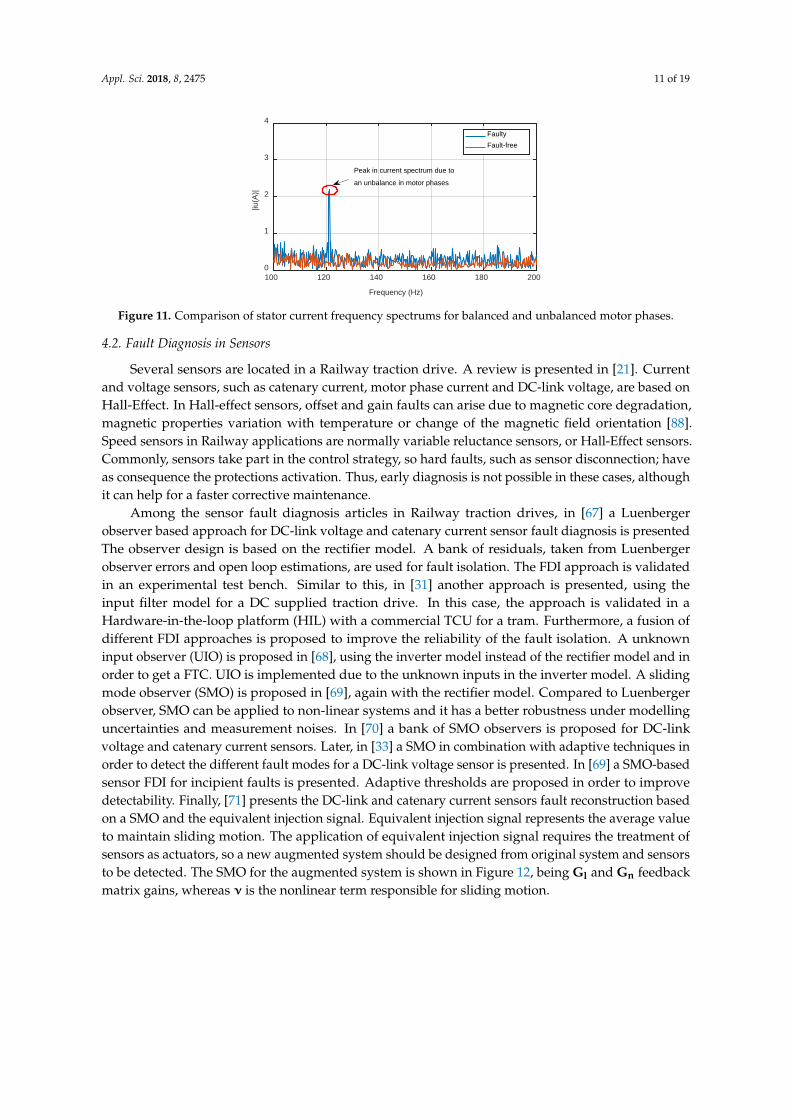
Despite the variety of fault diagnosis approaches for induction machines presented in theliterature [84–87], the application to Railway traction drives is more limited. Thus, in [63] the rotorbars faults are detected by Motor current signature analysis (MCSA) for an induction motor usedfor a high speed railway application. MCSA is one of the most usual signal-based FDI approach forfault detection in electric machines. MCSA is based on stator current frequency spectrum analysisfor faulty induction machine in comparison to a fault-free induction machine and its main drawbackis that it can be only applied in steady state. An example for an induction motor with unbalancedphases is shown in Figure 11. Faults such as rotor bars breakage, eccentricity or inter-turn short-circuitscan be detected [30] with this strategy. On the other hand, in [64] the oscillation that arises in theflux when a rotor fault occurs is analysed. The oscillation frequency is twice the slip frequency.This approach, called Virtual Current Technique (VCT), can be used in transient and steady states.Furthermore, compared to other techniques as Vienna Monitoring Method (VMM), VCT allows linkingthe oscillation and the number of broken rotor bars. FFT is used too in [65] to detect dirt in motors,as the accumulation of electromagnetic material generates changes in the flux harmonics amplitudes.Finally, in [66] the motor winding insulation degradation is detected. Inverter applies a step voltageto each motor phase and transient current are analysed. An insulation degradation is revealed in aparasitic capacitor change, being the capacitor the main factor for the current transient behaviour.
Appl. Sci. 2018, 8, 2475 11 of 19Appl. Sci. 2018, 8, x FOR PEER REVIEW 11 of 19
Figure 11. Comparison of stator current frequency spectrums for balanced and unbalanced motor phases.
4.2. Fault Diagnosis in Sensors
Several sensors are located in a Railway traction drive. A review is presented in [21]. Current and voltage sensors, such as catenary current, motor phase current and DC-link voltage, are based on Hall-Effect. In Hall-effect sensors, offset and gain faults can arise due to magnetic core degradation, magnetic properties variation with temperature or change of the magnetic field orientation [88]. Speed sensors in Railway applications are normally variable reluctance sensors, or Hall-Effect sensors. Commonly, sensors take part in the control strategy, so hard faults, such as sensor disconnection; have as consequence the protections activation. Thus, early diagnosis is not possible in these cases, although it can help for a faster corrective maintenance.
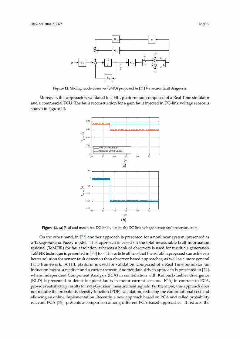
Among the sensor fault diagnosis articles in Railway traction drives, in [67] a Luenberger observer based approach for DC-link voltage and catenary current sensor fault diagnosis is presented The observer design is based on the rectifier model. A bank of residuals, taken from Luenberger observer errors and open loop estimations, are used for fault isolation. The FDI approach is validated in an experimental test bench. Similar to this, in [31] another approach is presented, using the input filter model for a DC supplied traction drive. In this case, the approach is validated in a Hardware-in-the-loop platform (HIL) with a commercial TCU for a tram. Furthermore, a fusion of different FDI approaches is proposed to improve the reliability of the fault isolation. A unknown input observer (UIO) is proposed in [68], using the inverter model instead of the rectifier model and in order to get a FTC. UIO is implemented due to the unknown inputs in the inverter model. A sliding mode observer (SMO) is proposed in [69], again with the rectifier model. Compared to Luenberger observer, SMO can be applied to non-linear systems and it has a better robustness under modelling uncertainties and measurement noises. In [70] a bank of SMO observers is proposed for DC-link voltage and catenary current sensors. Later, in [33] a SMO in combination with adaptive techniques in order to detect the different fault modes for a DC-link voltage sensor is presented. In [69] a SMO-based sensor FDI for incipient faults is presented. Adaptive thresholds are proposed in order to improve detectability. Finally, [71] presents the DC-link and catenary current sensors fault reconstruction based on a SMO and the equivalent injection signal. Equivalent injection signal represents the average value to maintain sliding motion. The application of equivalent injection signal requires the treatment of sensors as actuators, so a new augmented system should be designed from original system and sensors to be detected. The SMO for the augmented system is shown in Figure 12, being Gl and Gn feedback matrix gains, whereas ν is the nonlinear term responsible for sliding motion.
100 120 140 160 180 200
Frequency (Hz)
0
1
2
3
4
|iu(A
)|
FaultyFault-free
Peak in current spectrum due to
an unbalance in motor phases
Figure 11. Comparison of stator current frequency spectrums for balanced and unbalanced motor phases.
4.2. Fault Diagnosis in Sensors
Several sensors are located in a Railway traction drive. A review is presented in [21]. Currentand voltage sensors, such as catenary current, motor phase current and DC-link voltage, are based onHall-Effect. In Hall-effect sensors, offset and gain faults can arise due to magnetic core degradation,magnetic properties variation with temperature or change of the magnetic field orientation [88].Speed sensors in Railway applications are normally variable reluctance sensors, or Hall-Effect sensors.Commonly, sensors take part in the control strategy, so hard faults, such as sensor disconnection; haveas consequence the protections activation. Thus, early diagnosis is not possible in these cases, althoughit can help for a faster corrective maintenance.
Among the sensor fault diagnosis articles in Railway traction drives, in [67] a Luenbergerobserver based approach for DC-link voltage and catenary current sensor fault diagnosis is presentedThe observer design is based on the rectifier model. A bank of residuals, taken from Luenbergerobserver errors and open loop estimations, are used for fault isolation. The FDI approach is validatedin an experimental test bench. Similar to this, in [31] another approach is presented, using theinput filter model for a DC supplied traction drive. In this case, the approach is validated in aHardware-in-the-loop platform (HIL) with a commercial TCU for a tram. Furthermore, a fusion ofdifferent FDI approaches is proposed to improve the reliability of the fault isolation. A unknowninput observer (UIO) is proposed in [68], using the inverter model instead of the rectifier model and inorder to get a FTC. UIO is implemented due to the unknown inputs in the inverter model. A slidingmode observer (SMO) is proposed in [69], again with the rectifier model. Compared to Luenbergerobserver, SMO can be applied to non-linear systems and it has a better robustness under modellinguncertainties and measurement noises. In [70] a bank of SMO observers is proposed for DC-linkvoltage and catenary current sensors. Later, in [33] a SMO in combination with adaptive techniques inorder to detect the different fault modes for a DC-link voltage sensor is presented. In [69] a SMO-basedsensor FDI for incipient faults is presented. Adaptive thresholds are proposed in order to improvedetectability. Finally, [71] presents the DC-link and catenary current sensors fault reconstruction basedon a SMO and the equivalent injection signal. Equivalent injection signal represents the average valueto maintain sliding motion. The application of equivalent injection signal requires the treatment ofsensors as actuators, so a new augmented system should be designed from original system and sensorsto be detected. The SMO for the augmented system is shown in Figure 12, being Gl and Gn feedbackmatrix gains, whereas ν is the nonlinear term responsible for sliding motion.
Appl. Sci. 2018, 8, 2475 12 of 19Appl. Sci. 2018, 8, x FOR PEER REVIEW 12 of 19
B 0 ∫ C 0
A 0
G n
++
+
+-
-+
u
G l-
+
ez1
ez2
v
xz
z1z2
z1
z2
Figure 12. Sliding mode observer (SMO) proposed in [71] for sensor fault diagnosis.
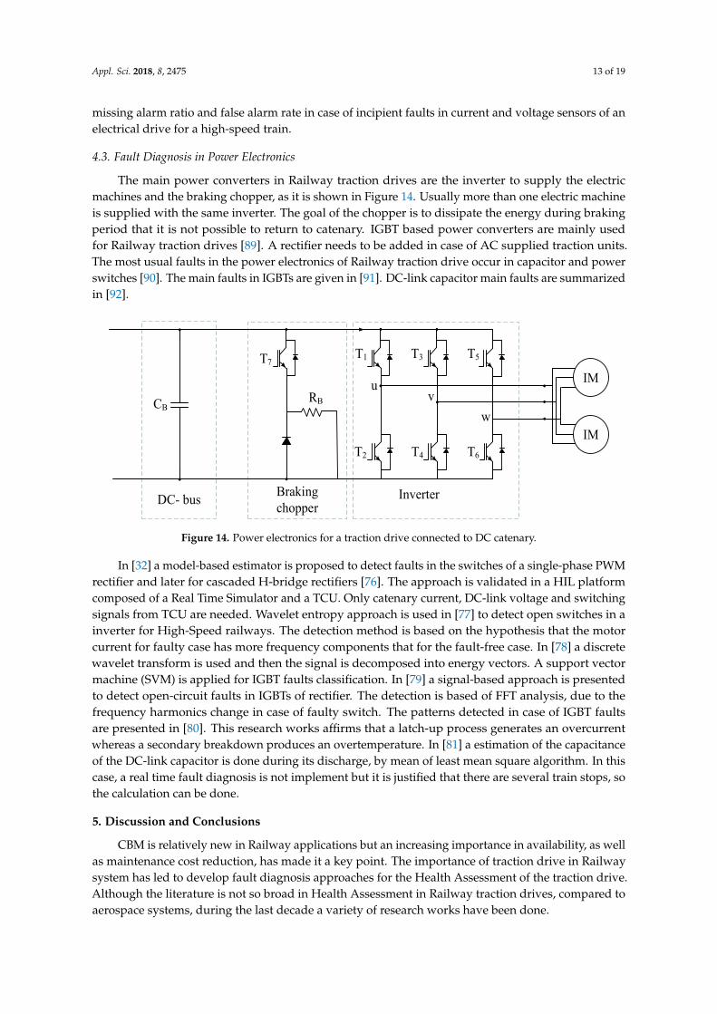
Moreover, this approach is validated in a HIL platform too, composed of a Real Time simulator and a commercial TCU. The fault reconstruction for a gain fault injected in DC-link voltage sensor is shown in Figure 13.
On the other hand, in [72] another approach is presented for a nonlinear system, presented as a Takagi-Sukeno Fuzzy model. This approach is based on the total measurable fault information residual (ToMFIR) for fault isolation, whereas a bank of observers is used for residuals generation. ToMFIR technique is presented in [73] too. This article affirms that the solution proposed can achieve a better solution for sensor fault detection than observer-based approaches, as well as a more general FDD framework. A HIL platform is used for validation, composed of a Real Time Simulator, an induction motor, a rectifier and a current sensor. Another data-driven approach is presented in [74], where Independent Component Analysis (ICA) in combination with Kullback-Leibler divergence (KLD) is presented to detect incipient faults in motor current sensors. ICA, in contrast to PCA, provides satisfactory results for non-Gaussian measurement signals. Furthermore, this approach does not require the probability density function (PDF) calculation, reducing the computational cost and allowing an online implementation. Recently, a new approach based on PCA and called probability relevant PCA [75], presents a comparison among different PCA-based approaches. It reduces the missing alarm ratio and false alarm rate in case of incipient faults in current and voltage sensors of an electrical drive for a high-speed train.
(a)
(b)
Figure 13. (a) Real and measured DC-link voltage; (b) DC-link voltage sensor fault reconstruction.
v bus (V
)f vb
us (V
)
Figure 12. Sliding mode observer (SMO) proposed in [71] for sensor fault diagnosis.
Moreover, this approach is validated in a HIL platform too, composed of a Real Time simulatorand a commercial TCU. The fault reconstruction for a gain fault injected in DC-link voltage sensor isshown in Figure 13.
Appl. Sci. 2018, 8, x FOR PEER REVIEW 12 of 19
B 0 ∫ C 0
A 0
G n
++
+
+-
-+
u
G l-
+
ez1
ez2
v
xz
z1
z2
z1
z2
Figure 12. Sliding mode observer (SMO) proposed in [71] for sensor fault diagnosis.
Moreover, this approach is validated in a HIL platform too, composed of a Real Time simulator and a commercial TCU. The fault reconstruction for a gain fault injected in DC-link voltage sensor is shown in Figure 13.
On the other hand, in [72] another approach is presented for a nonlinear system, presented as a Takagi-Sukeno Fuzzy model. This approach is based on the total measurable fault information residual (ToMFIR) for fault isolation, whereas a bank of observers is used for residuals generation. ToMFIR technique is presented in [73] too. This article affirms that the solution proposed can achieve a better solution for sensor fault detection than observer-based approaches, as well as a more general FDD framework. A HIL platform is used for validation, composed of a Real Time Simulator, an induction motor, a rectifier and a current sensor. Another data-driven approach is presented in [74], where Independent Component Analysis (ICA) in combination with Kullback-Leibler divergence (KLD) is presented to detect incipient faults in motor current sensors. ICA, in contrast to PCA, provides satisfactory results for non-Gaussian measurement signals. Furthermore, this approach does not require the probability density function (PDF) calculation, reducing the computational cost and allowing an online implementation. Recently, a new approach based on PCA and called probability relevant PCA [75], presents a comparison among different PCA-based approaches. It reduces the missing alarm ratio and false alarm rate in case of incipient faults in current and voltage sensors of an electrical drive for a high-speed train.
(a)
(b)
Figure 13. (a) Real and measured DC-link voltage; (b) DC-link voltage sensor fault reconstruction.
20 30 40 50 60 70
t (s)
0
200
400
600
800
v bu
s (V
)
Real DC-link voltageMeasured DC-link voltage
20 30 40 50 60 70
t (s)
-200
-150
-100
-50
0
50
f vb
us
(V)
Figure 13. (a) Real and measured DC-link voltage; (b) DC-link voltage sensor fault reconstruction.
On the other hand, in [72] another approach is presented for a nonlinear system, presented asa Takagi-Sukeno Fuzzy model. This approach is based on the total measurable fault informationresidual (ToMFIR) for fault isolation, whereas a bank of observers is used for residuals generation.ToMFIR technique is presented in [73] too. This article affirms that the solution proposed can achieve abetter solution for sensor fault detection than observer-based approaches, as well as a more generalFDD framework. A HIL platform is used for validation, composed of a Real Time Simulator, aninduction motor, a rectifier and a current sensor. Another data-driven approach is presented in [74],where Independent Component Analysis (ICA) in combination with Kullback-Leibler divergence(KLD) is presented to detect incipient faults in motor current sensors. ICA, in contrast to PCA,provides satisfactory results for non-Gaussian measurement signals. Furthermore, this approach doesnot require the probability density function (PDF) calculation, reducing the computational cost andallowing an online implementation. Recently, a new approach based on PCA and called probabilityrelevant PCA [75], presents a comparison among different PCA-based approaches. It reduces the
Appl. Sci. 2018, 8, 2475 13 of 19
missing alarm ratio and false alarm rate in case of incipient faults in current and voltage sensors of anelectrical drive for a high-speed train.
4.3. Fault Diagnosis in Power Electronics
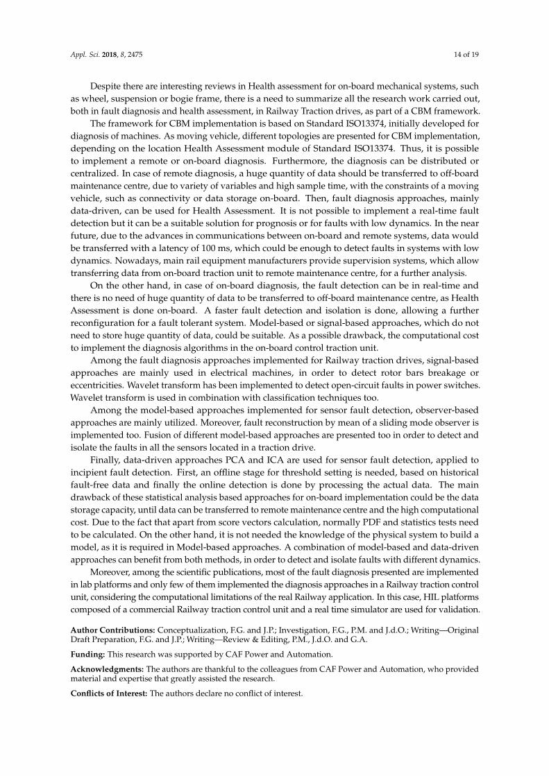
The main power converters in Railway traction drives are the inverter to supply the electricmachines and the braking chopper, as it is shown in Figure 14. Usually more than one electric machineis supplied with the same inverter. The goal of the chopper is to dissipate the energy during brakingperiod that it is not possible to return to catenary. IGBT based power converters are mainly usedfor Railway traction drives [89]. A rectifier needs to be added in case of AC supplied traction units.The most usual faults in the power electronics of Railway traction drive occur in capacitor and powerswitches [90]. The main faults in IGBTs are given in [91]. DC-link capacitor main faults are summarizedin [92].
Appl. Sci. 2018, 8, x FOR PEER REVIEW 13 of 19
4.3. Fault Diagnosis in Power Electronics
The main power converters in Railway traction drives are the inverter to supply the electric machines and the braking chopper, as it is shown in Figure 14. Usually more than one electric machine is supplied with the same inverter. The goal of the chopper is to dissipate the energy during braking period that it is not possible to return to catenary. IGBT based power converters are mainly used for Railway traction drives [89]. A rectifier needs to be added in case of AC supplied traction units. The most usual faults in the power electronics of Railway traction drive occur in capacitor and power switches [90]. The main faults in IGBTs are given in [91]. DC-link capacitor main faults are summarized in [92].
T1 T3 T5
uv
w
T2 T4 T6
T7
RBCB
MIM
MIM
InverterBrakingchopperDC- bus
Figure 14. Power electronics for a traction drive connected to DC catenary.
In [32] a model-based estimator is proposed to detect faults in the switches of a single-phase PWM rectifier and later for cascaded H-bridge rectifiers [76]. The approach is validated in a HIL platform composed of a Real Time Simulator and a TCU. Only catenary current, DC-link voltage and switching signals from TCU are needed. Wavelet entropy approach is used in [77] to detect open switches in a inverter for High-Speed railways. The detection method is based on the hypothesis that the motor current for faulty case has more frequency components that for the fault-free case. In [78] a discrete wavelet transform is used and then the signal is decomposed into energy vectors. A support vector machine (SVM) is applied for IGBT faults classification. In [79] a signal-based approach is presented to detect open-circuit faults in IGBTs of rectifier. The detection is based of FFT analysis, due to the frequency harmonics change in case of faulty switch. The patterns detected in case of IGBT faults are presented in [80]. This research works affirms that a latch-up process generates an overcurrent whereas a secondary breakdown produces an overtemperature. In [81] a estimation of the capacitance of the DC-link capacitor is done during its discharge, by mean of least mean square algorithm. In this case, a real time fault diagnosis is not implement but it is justified that there are several train stops, so the calculation can be done.
5. Discussion and Conclusions
CBM is relatively new in Railway applications but an increasing importance in availability, as well as maintenance cost reduction, has made it a key point. The importance of traction drive in Railway system has led to develop fault diagnosis approaches for the Health Assessment of the traction drive. Although the literature is not so broad in Health Assessment in Railway traction drives, compared to aerospace systems, during the last decade a variety of research works have been done.
Despite there are interesting reviews in Health assessment for on-board mechanical systems, such as wheel, suspension or bogie frame, there is a need to summarize all the research work carried out, both in fault diagnosis and health assessment, in Railway Traction drives, as part of a CBM framework.
Figure 14. Power electronics for a traction drive connected to DC catenary.
In [32] a model-based estimator is proposed to detect faults in the switches of a single-phase PWMrectifier and later for cascaded H-bridge rectifiers [76]. The approach is validated in a HIL platformcomposed of a Real Time Simulator and a TCU. Only catenary current, DC-link voltage and switchingsignals from TCU are needed. Wavelet entropy approach is used in [77] to detect open switches in ainverter for High-Speed railways. The detection method is based on the hypothesis that the motorcurrent for faulty case has more frequency components that for the fault-free case. In [78] a discretewavelet transform is used and then the signal is decomposed into energy vectors. A support vectormachine (SVM) is applied for IGBT faults classification. In [79] a signal-based approach is presentedto detect open-circuit faults in IGBTs of rectifier. The detection is based of FFT analysis, due to thefrequency harmonics change in case of faulty switch. The patterns detected in case of IGBT faultsare presented in [80]. This research works affirms that a latch-up process generates an overcurrentwhereas a secondary breakdown produces an overtemperature. In [81] a estimation of the capacitanceof the DC-link capacitor is done during its discharge, by mean of least mean square algorithm. In thiscase, a real time fault diagnosis is not implement but it is justified that there are several train stops, sothe calculation can be done.
5. Discussion and Conclusions
CBM is relatively new in Railway applications but an increasing importance in availability, as wellas maintenance cost reduction, has made it a key point. The importance of traction drive in Railwaysystem has led to develop fault diagnosis approaches for the Health Assessment of the traction drive.Although the literature is not so broad in Health Assessment in Railway traction drives, compared toaerospace systems, during the last decade a variety of research works have been done.
Appl. Sci. 2018, 8, 2475 14 of 19
Despite there are interesting reviews in Health assessment for on-board mechanical systems, suchas wheel, suspension or bogie frame, there is a need to summarize all the research work carried out,both in fault diagnosis and health assessment, in Railway Traction drives, as part of a CBM framework.
The framework for CBM implementation is based on Standard ISO13374, initially developed fordiagnosis of machines. As moving vehicle, different topologies are presented for CBM implementation,depending on the location Health Assessment module of Standard ISO13374. Thus, it is possibleto implement a remote or on-board diagnosis. Furthermore, the diagnosis can be distributed orcentralized. In case of remote diagnosis, a huge quantity of data should be transferred to off-boardmaintenance centre, due to variety of variables and high sample time, with the constraints of a movingvehicle, such as connectivity or data storage on-board. Then, fault diagnosis approaches, mainlydata-driven, can be used for Health Assessment. It is not possible to implement a real-time faultdetection but it can be a suitable solution for prognosis or for faults with low dynamics. In the nearfuture, due to the advances in communications between on-board and remote systems, data wouldbe transferred with a latency of 100 ms, which could be enough to detect faults in systems with lowdynamics. Nowadays, main rail equipment manufacturers provide supervision systems, which allowtransferring data from on-board traction unit to remote maintenance centre, for a further analysis.
On the other hand, in case of on-board diagnosis, the fault detection can be in real-time andthere is no need of huge quantity of data to be transferred to off-board maintenance centre, as HealthAssessment is done on-board. A faster fault detection and isolation is done, allowing a furtherreconfiguration for a fault tolerant system. Model-based or signal-based approaches, which do notneed to store huge quantity of data, could be suitable. As a possible drawback, the computational costto implement the diagnosis algorithms in the on-board control traction unit.
Among the fault diagnosis approaches implemented for Railway traction drives, signal-basedapproaches are mainly used in electrical machines, in order to detect rotor bars breakage oreccentricities. Wavelet transform has been implemented to detect open-circuit faults in power switches.Wavelet transform is used in combination with classification techniques too.
Among the model-based approaches implemented for sensor fault detection, observer-basedapproaches are mainly utilized. Moreover, fault reconstruction by mean of a sliding mode observer isimplemented too. Fusion of different model-based approaches are presented too in order to detect andisolate the faults in all the sensors located in a traction drive.
Finally, data-driven approaches PCA and ICA are used for sensor fault detection, applied toincipient fault detection. First, an offline stage for threshold setting is needed, based on historicalfault-free data and finally the online detection is done by processing the actual data. The maindrawback of these statistical analysis based approaches for on-board implementation could be the datastorage capacity, until data can be transferred to remote maintenance centre and the high computationalcost. Due to the fact that apart from score vectors calculation, normally PDF and statistics tests needto be calculated. On the other hand, it is not needed the knowledge of the physical system to build amodel, as it is required in Model-based approaches. A combination of model-based and data-drivenapproaches can benefit from both methods, in order to detect and isolate faults with different dynamics.
Moreover, among the scientific publications, most of the fault diagnosis presented are implementedin lab platforms and only few of them implemented the diagnosis approaches in a Railway traction controlunit, considering the computational limitations of the real Railway application. In this case, HIL platformscomposed of a commercial Railway traction control unit and a real time simulator are used for validation.
Author Contributions: Conceptualization, F.G. and J.P.; Investigation, F.G., P.M. and J.d.O.; Writing—OriginalDraft Preparation, F.G. and J.P.; Writing—Review & Editing, P.M., J.d.O. and G.A.
Funding: This research was supported by CAF Power and Automation.
Acknowledgments: The authors are thankful to the colleagues from CAF Power and Automation, who providedmaterial and expertise that greatly assisted the research.
Conflicts of Interest: The authors declare no conflict of interest.
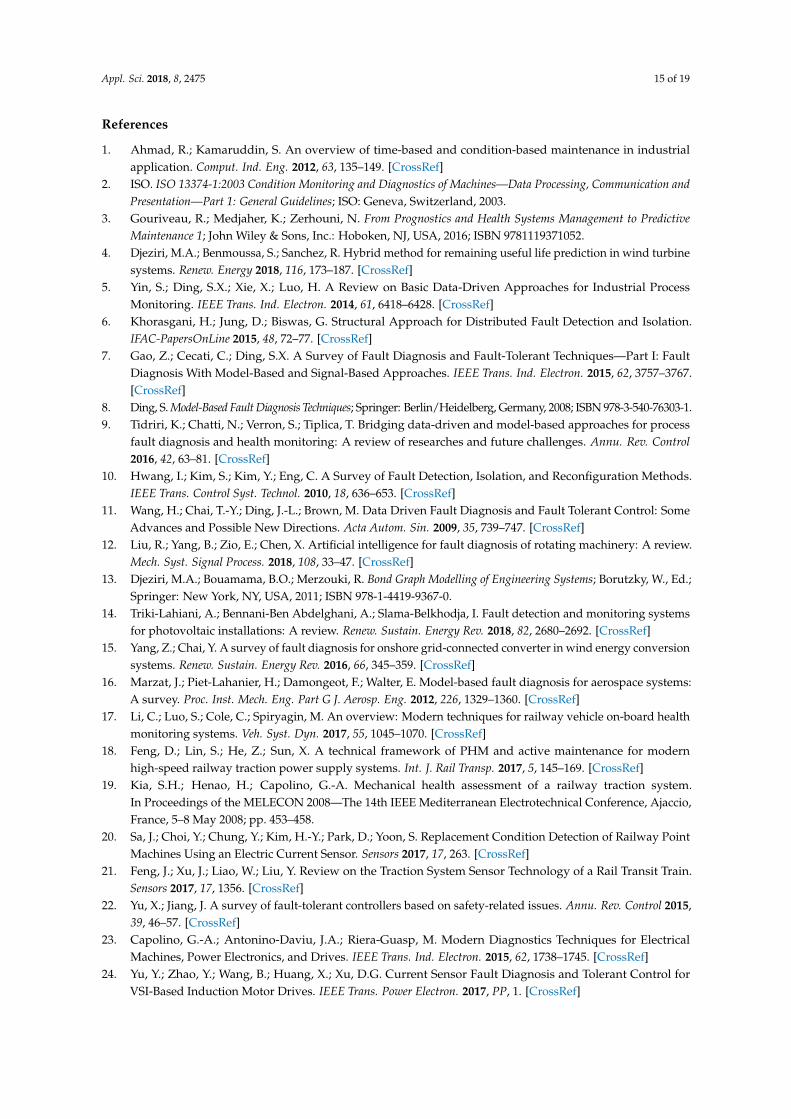
Appl. Sci. 2018, 8, 2475 15 of 19
References
1. Ahmad, R.; Kamaruddin, S. An overview of time-based and condition-based maintenance in industrialapplication. Comput. Ind. Eng. 2012, 63, 135–149. [CrossRef]
2. ISO. ISO 13374-1:2003 Condition Monitoring and Diagnostics of Machines—Data Processing, Communication andPresentation—Part 1: General Guidelines; ISO: Geneva, Switzerland, 2003.
3. Gouriveau, R.; Medjaher, K.; Zerhouni, N. From Prognostics and Health Systems Management to PredictiveMaintenance 1; John Wiley & Sons, Inc.: Hoboken, NJ, USA, 2016; ISBN 9781119371052.
4. Djeziri, M.A.; Benmoussa, S.; Sanchez, R. Hybrid method for remaining useful life prediction in wind turbinesystems. Renew. Energy 2018, 116, 173–187. [CrossRef]
5. Yin, S.; Ding, S.X.; Xie, X.; Luo, H. A Review on Basic Data-Driven Approaches for Industrial ProcessMonitoring. IEEE Trans. Ind. Electron. 2014, 61, 6418–6428. [CrossRef]
6. Khorasgani, H.; Jung, D.; Biswas, G. Structural Approach for Distributed Fault Detection and Isolation.IFAC-PapersOnLine 2015, 48, 72–77. [CrossRef]
7. Gao, Z.; Cecati, C.; Ding, S.X. A Survey of Fault Diagnosis and Fault-Tolerant Techniques—Part I: FaultDiagnosis With Model-Based and Signal-Based Approaches. IEEE Trans. Ind. Electron. 2015, 62, 3757–3767.[CrossRef]
8. Ding, S. Model-Based Fault Diagnosis Techniques; Springer: Berlin/Heidelberg, Germany, 2008; ISBN 978-3-540-76303-1.9. Tidriri, K.; Chatti, N.; Verron, S.; Tiplica, T. Bridging data-driven and model-based approaches for process
fault diagnosis and health monitoring: A review of researches and future challenges. Annu. Rev. Control2016, 42, 63–81. [CrossRef]
10. Hwang, I.; Kim, S.; Kim, Y.; Eng, C. A Survey of Fault Detection, Isolation, and Reconfiguration Methods.IEEE Trans. Control Syst. Technol. 2010, 18, 636–653. [CrossRef]
11. Wang, H.; Chai, T.-Y.; Ding, J.-L.; Brown, M. Data Driven Fault Diagnosis and Fault Tolerant Control: SomeAdvances and Possible New Directions. Acta Autom. Sin. 2009, 35, 739–747. [CrossRef]
12. Liu, R.; Yang, B.; Zio, E.; Chen, X. Artificial intelligence for fault diagnosis of rotating machinery: A review.Mech. Syst. Signal Process. 2018, 108, 33–47. [CrossRef]
13. Djeziri, M.A.; Bouamama, B.O.; Merzouki, R. Bond Graph Modelling of Engineering Systems; Borutzky, W., Ed.;Springer: New York, NY, USA, 2011; ISBN 978-1-4419-9367-0.
14. Triki-Lahiani, A.; Bennani-Ben Abdelghani, A.; Slama-Belkhodja, I. Fault detection and monitoring systemsfor photovoltaic installations: A review. Renew. Sustain. Energy Rev. 2018, 82, 2680–2692. [CrossRef]
15. Yang, Z.; Chai, Y. A survey of fault diagnosis for onshore grid-connected converter in wind energy conversionsystems. Renew. Sustain. Energy Rev. 2016, 66, 345–359. [CrossRef]
16. Marzat, J.; Piet-Lahanier, H.; Damongeot, F.; Walter, E. Model-based fault diagnosis for aerospace systems:A survey. Proc. Inst. Mech. Eng. Part G J. Aerosp. Eng. 2012, 226, 1329–1360. [CrossRef]
17. Li, C.; Luo, S.; Cole, C.; Spiryagin, M. An overview: Modern techniques for railway vehicle on-board healthmonitoring systems. Veh. Syst. Dyn. 2017, 55, 1045–1070. [CrossRef]
18. Feng, D.; Lin, S.; He, Z.; Sun, X. A technical framework of PHM and active maintenance for modernhigh-speed railway traction power supply systems. Int. J. Rail Transp. 2017, 5, 145–169. [CrossRef]
19. Kia, S.H.; Henao, H.; Capolino, G.-A. Mechanical health assessment of a railway traction system.In Proceedings of the MELECON 2008—The 14th IEEE Mediterranean Electrotechnical Conference, Ajaccio,France, 5–8 May 2008; pp. 453–458.
20. Sa, J.; Choi, Y.; Chung, Y.; Kim, H.-Y.; Park, D.; Yoon, S. Replacement Condition Detection of Railway PointMachines Using an Electric Current Sensor. Sensors 2017, 17, 263. [CrossRef]
21. Feng, J.; Xu, J.; Liao, W.; Liu, Y. Review on the Traction System Sensor Technology of a Rail Transit Train.Sensors 2017, 17, 1356. [CrossRef]
22. Yu, X.; Jiang, J. A survey of fault-tolerant controllers based on safety-related issues. Annu. Rev. Control 2015,39, 46–57. [CrossRef]
23. Capolino, G.-A.; Antonino-Daviu, J.A.; Riera-Guasp, M. Modern Diagnostics Techniques for ElectricalMachines, Power Electronics, and Drives. IEEE Trans. Ind. Electron. 2015, 62, 1738–1745. [CrossRef]
24. Yu, Y.; Zhao, Y.; Wang, B.; Huang, X.; Xu, D.G. Current Sensor Fault Diagnosis and Tolerant Control forVSI-Based Induction Motor Drives. IEEE Trans. Power Electron. 2017, PP, 1. [CrossRef]
Appl. Sci. 2018, 8, 2475 16 of 19
25. Najafabadi, T.A.; Salmasi, F.R.; Jabehdar-Maralani, P. Detection and isolation of speed-, DC-link voltage-,and current-sensor faults based on an adaptive observer in induction-motor drives. IEEE Trans. Ind. Electron.2011, 58, 1662–1672. [CrossRef]
26. Bourogaoui, M.; Sethom, H.B.A.; Belkhodja, I.S. Speed/position sensor fault tolerant control in adjustablespeed drives—A review. ISA Trans. 2016, 64, 269–284. [CrossRef] [PubMed]
27. Poon, J.; Jain, P.; Konstantakopoulos, I.C.; Spanos, C.; Panda, S.K.; Sanders, S.R. Model-Based Fault Detectionand Identification for Switching Power Converters. IEEE Trans. Power Electron. 2017, 32, 1419–1430.[CrossRef]
28. Merizalde, Y.; Hernández-Callejo, L.; Duque-Perez, O. State of the Art and Trends in the Monitoring,Detection and Diagnosis of Failures in Electric Induction Motors. Energies 2017, 10, 1056. [CrossRef]
29. Liu, Y.; Bazzi, A.M. A review and comparison of fault detection and diagnosis methods for squirrel-cageinduction motors: State of the art. ISA Trans. 2017, 70, 400–409. [CrossRef]
30. Riera-Guasp, M.; Antonino-Daviu, J.A.; Capolino, G.-A. Advances in Electrical Machine, Power Electronic,and Drive Condition Monitoring and Fault Detection: State of the Art. IEEE Trans. Ind. Electron. 2015, 62,1746–1759. [CrossRef]
31. Garramiola, F.; del Olmo, J.; Poza, J.; Madina, P.; Almandoz, G. Integral Sensor Fault Detection and Isolationfor Railway Traction Drive. Sensors 2018, 18, 1543. [CrossRef] [PubMed]
32. Gou, B.; Ge, X.; Wang, S.; Feng, X.; Kuo, J.B.; Habetler, T.G. An Open-Switch Fault Diagnosis Method forSingle-Phase PWM Rectifier Using a Model-Based Approach in High-Speed Railway Electrical TractionDrive System. IEEE Trans. Power Electron. 2016, 31, 3816–3826. [CrossRef]
33. Zhang, K.; Jiang, B.; Yan, X.-G.; Mao, Z. Incipient Voltage Sensor Fault Isolation for Rectifier in RailwayElectrical Traction Systems. IEEE Trans. Ind. Electron. 2017, PP, 1. [CrossRef]
34. Jardine, A.K.S.; Lin, D.; Banjevic, D. A review on machinery diagnostics and prognostics implementingcondition-based maintenance. Mech. Syst. Signal Process. 2006, 20, 1483–1510. [CrossRef]
35. Alaswad, S.; Xiang, Y. A review on condition-based maintenance optimization models for stochasticallydeteriorating system. Reliab. Eng. Syst. Saf. 2017, 157, 54–63. [CrossRef]
36. Olde Keizer, M.C.A.; Flapper, S.D.P.; Teunter, R.H. Condition-based maintenance policies for systems withmultiple dependent components: A review. Eur. J. Oper. Res. 2017, 261, 405–420. [CrossRef]
37. Shin, J.-H.; Jun, H.-B. On condition based maintenance policy. J. Comput. Des. Eng. 2015, 2, 119–127. [CrossRef]38. de Jonge, B.; Teunter, R.; Tinga, T. The influence of practical factors on the benefits of condition-based
maintenance over time-based maintenance. Reliab. Eng. Syst. Saf. 2017, 158, 21–30. [CrossRef]39. Guillén, A.J.; Crespo, A.; Gómez, J.F.; Sanz, M.D. A framework for effective management of condition based
maintenance programs in the context of industrial development of E-Maintenance strategies. Comput. Ind.2016, 82, 170–185. [CrossRef]
40. Del Olmo, J.; Poza, J.; Garramiola, F.; Nieva, T.; Aldasoro, L. Model driven Hardware-in-the-Loop Faultanalysis of railway traction systems. In Proceedings of the 2017 IEEE International Workshop of Electronics,Control, Measurement, Signals and their Application to Mechatronics (ECMSM), San Sebastian, Spain, 24–26May 2017; pp. 1–6.
41. Le Mortellec, A. Proposition d’une Architecture de Surveillance “Active” à base d’agents Intelligents Pour l’aideà la Maintenance de Systèmes Mobiles Application au Domaine Ferroviaire; Université de Valenciennes et duHainaut-Cambresis: Famars, France, 2014.
42. Ai, B.; Guan, K.; Rupp, M.; Kurner, T.; Cheng, X.; Yin, X.-F.; Wang, Q.; Ma, G.-Y.; Li, Y.; Xiong, L.; et al. Futurerailway services-oriented mobile communications network. IEEE Commun. Mag. 2015, 53, 78–85. [CrossRef]
43. Jiang, X.; Li, G. Research on Fault Prognostics and Health Management of the on-Board Equipment ofCTCS-3 Train Control System. Int. J. Secur. Appl. 2016, 10, 175–186. [CrossRef]
44. Ciocoiu, L.; Siemieniuch, C.E.; Hubbard, E.-M. From preventative to predictive maintenance: The organisationalchallenge. Proc. Inst. Mech. Eng. Part F J. Rail Rapid Transit 2017, 231, 1174–1185. [CrossRef]
45. Yokoyama, A. Innovative Changes for Maintenance of Railway by Using ICT–To Achieve “Smart Maintenance”.Procedia CIRP 2015, 38, 24–29. [CrossRef]
46. Shift2Rail. Available online: https://shift2rail.org/ (accessed on 29 November 2018).47. Yang, C.; Yang, C.; Peng, T.; Yang, X.; Weihua, G. A Fault-Injection Strategy for Traction Drive Control
Systems. IEEE Trans. Ind. Electron. 2017, PP, 1. [CrossRef]
Appl. Sci. 2018, 8, 2475 17 of 19
48. del Olmo, J.; Garramiola, F.; Poza, J.; Almandoz, G. Model-Based Fault Analysis for Railway Traction Systems.In Modern Railway Engineering; Hessami, A., Ed.; InTech: Rijeka, Croatia, 2018; ISBN 978-953-51-3860-0.
49. Yang, X.; Yang, C.; Peng, T.; Chen, Z.; Liu, B.; Gui, W. Hardware-in-the-Loop Fault Injection for TractionControl System. IEEE J. Emerg. Sel. Top. Power Electron. 2018, 6, 696–706. [CrossRef]
50. Fraga-Lamas, P.; Fernández-Caramés, T.M.; Castedo, L. Towards the Internet of Smart Trains: A Review onIndustrial IoT-Connected Railways. Sensors 2017, 17, 1457. [CrossRef] [PubMed]
51. Atamuradov, V.; Medjaher, K.; Dersin, P.; Lamoureux, B.; Zerhouni, N. Prognostics and Health Managementfor Maintenance Practitioners -Review, Implementation and Tools Evaluation. Int. J. Progn. Heal. Manag.2017, 2153–2648.
52. Karakose, M.; Yaman, O.; Murat, K.; Akin, E. A New Approach for Condition Monitoring and Detection ofRail Components and Rail Track in Railway. Int. J. Comput. Intell. Syst. 2018, 11, 830–845. [CrossRef]
53. Wu, Y.; Qin, Y.; Wang, Z.; Jia, L. A UAV-Based Visual Inspection Method for Rail Surface Defects. Appl. Sci.2018, 8, 1028. [CrossRef]
54. Wei, J.; Liu, C.; Ren, T.; Liu, H.; Zhou, W. Online Condition Monitoring of a Rail Fastening System onHigh-Speed Railways Based on Wavelet Packet Analysis. Sensors 2017, 17, 318. [CrossRef] [PubMed]
55. Gao, R.X.; Yan, R. Wavelets; Springer: Boston, MA, USA, 2011; ISBN 978-1-4419-1544-3.56. Gómez, M.; Corral, E.; Castejón, C.; García-Prada, J. Effective Crack Detection in Railway Axles Using
Vibration Signals and WPT Energy. Sensors 2018, 18, 1603. [CrossRef]57. Cheng, Y.; Zhou, N.; Zhang, W.; Wang, Z. Application of an improved minimum entropy deconvolution
method for railway rolling element bearing fault diagnosis. J. Sound Vib. 2018, 425, 53–69. [CrossRef]58. Espinosa, F.; García, J.J.; Hernández, A.; Mazo, M.; Ureña, J.; Jiménez, J.A.; Fernández, I.; Pérez, C.;
García, J.C. Advanced monitoring of rail breakage in double-track railway lines by means of PCA techniques.Appl. Soft Comput. 2018, 63, 1–13. [CrossRef]
59. Chen, Z. Data-Driven Fault Detection for Industrial Processes; Springer: Wiesbaden, Germany, 2017;ISBN 978-3-658-16755-4.
60. Dai, C.; Huang, K.; Hu, K.; Liu, Z. Fault diagnosis approach of traction transformers in high-speed railwaycombining kernel principal component analysis with random forest. IET Electr. Syst. Transp. 2016, 6, 202–206.[CrossRef]
61. Liu, Z.; Hu, K. A Model-Based Diagnosis System for a Traction Power Supply System. IEEE Trans. Ind. Inform.2017, 13, 2834–2843. [CrossRef]
62. Mao, Z.; Zhan, Y.; Tao, G.; Jiang, B.; Yan, X.-G. Sensor Fault Detection for Rail Vehicle Suspension SystemsWith Disturbances and Stochastic Noises. IEEE Trans. Veh. Technol. 2017, 66, 4691–4705. [CrossRef]
63. Bruzzese, C.; Honorati, O.; Santini, E. Rotor bars breakage in railway traction squirrel cage induction motorsand diagnosis by MCSA technique Part I: Accurate fault simulations and spectral analyses. In Proceedingsof the 2005 5th IEEE International Symposium on Diagnostics for Electric Machines, Power Electronics andDrives, Vienna, Austria, 7–9 September 2005; pp. 1–6.
64. Cruz, S.M.A.; Stefani, A.; Filippetti, F.; Cardoso, A.J.M. A New Model-Based Technique for the Diagnosis ofRotor Faults in RFOC Induction Motor Drives. IEEE Trans. Ind. Electron. 2008, 55, 4218–4228. [CrossRef]
65. Sancho, C.; Gomez-Parra, M.; Munoz-Condes, P.; San Andres, M.A.G.; Gonzalez-Fernandez, F.J.; Carpio, J.;Guirado, R. Advanced Maintenance of Rail Traction Motors Using a Magnetic Leakage Flux Technique.IEEE Trans. Ind. Appl. 2012, 48, 942–951. [CrossRef]
66. Zoeller, C.; Vogelsberger, M.A.; Fasching, R.; Grubelnik, W.; Wolbank, T.M. Evaluation andCurrent-Response-Based Identification of Insulation Degradation for High Utilized Electrical Machines inRailway Application. IEEE Trans. Ind. Appl. 2017, 53, 2679–2689. [CrossRef]
67. Youssef, A.B.; El Khil, S.K.; Slama-Belkhodja, I. State Observer-Based Sensor Fault Detection and Isolation,and Fault Tolerant Control of a Single-Phase PWM Rectifier for Electric Railway Traction. IEEE Trans.Power Electron. 2013, 28, 5842–5853. [CrossRef]
68. Zhang, K.; Jiang, B.; Yan, X.-G.; Mao, Z. Incipient sensor fault estimation and accommodation for inverterdevices in electric railway traction systems. Int. J. Adapt. Control Signal Process. 2017, 31, 785–804. [CrossRef]
69. Zhang, K.; Jiang, B.; Yan, X.-G.; Mao, Z. Sliding mode observer based incipient sensor fault detection withapplication to high-speed railway traction device. ISA Trans. 2016, 63, 49–59. [CrossRef]
70. Xia, J.; Guo, Y.; Dai, B.; Zhang, X. Sensor Fault Diagnosis and System Reconfiguration Approach for ElectricTraction PWM Rectifier Based on Sliding Mode Observer. IEEE Trans. Ind. Appl. 2017, PP, 1. [CrossRef]
Appl. Sci. 2018, 8, 2475 18 of 19
71. Garramiola, F.; Poza, J.; del Olmo, J.; Madina, P.; Almandoz, G. DC-Link Voltage and Catenary CurrentSensors Fault Reconstruction for Railway Traction Drives. Sensors 2018, 18, 1998. [CrossRef]
72. Wu, Y.; Jiang, B.; Shi, P. Incipient fault diagnosis for T–S fuzzy systems with application to high-speedrailway traction devices. IET Control Theory Appl. 2016, 10, 2286–2297. [CrossRef]
73. Wu, Y.; Jiang, B.; Lu, N.; Yang, H.; Zhou, Y. Multiple incipient sensor faults diagnosis with application tohigh-speed railway traction devices. ISA Trans. 2017, 67, 183–192. [CrossRef]
74. Chen, H.; Jiang, B.; Lu, N.; Chen, W. Real-time incipient fault detection for electrical traction systems ofCRH2. Neurocomputing 2018, 306, 119–129. [CrossRef]
75. Chen, H.; Jiang, B.; Chen, W.; Yi, H. Data-driven Detection and Diagnosis of Incipient Faults in ElectricalDrives of High-Speed Trains. IEEE Trans. Ind. Electron. 2018, 1. [CrossRef]
76. Xie, D.; Ge, X. Open-circuit fault diagnosis for single-phase cascaded H-bridge rectifiers in electrical tractionsystems. In Proceedings of the 2017 IEEE Transportation Electrification Conference and Expo, Asia-Pacific(ITEC Asia-Pacific), Harbin, China, 7–10 August 2017; pp. 1–6.
77. Hu, K.; Liu, Z.; Lin, S. Wavelet Entropy-Based Traction Inverter Open Switch Fault Diagnosis in High-SpeedRailways. Entropy 2016, 18, 78. [CrossRef]
78. Fei, M.; Ning, L.; Huiyu, M.; Yi, P.; Haoyuan, S.; Jianyong, Z. On-line fault diagnosis model for locomotivetraction inverter based on wavelet transform and support vector machine. Microelectron. Reliab. 2018, 88–90,1274–1280. [CrossRef]
79. Tian, Z.; Ge, X. An on-line fault diagnostic method based on frequency-domain analysis for IGBTs in tractionPWM rectifiers. In Proceedings of the 2016 IEEE 8th International Power Electronics and Motion ControlConference (IPEMC-ECCE Asia), Hefei, China, 22–26 May 2016; pp. 3403–3407.
80. Perpiñà, X.; Serviere, J.F.; Jordà, X.; Fauquet, A.; Hidalgo, S.; Urresti-Ibañez, J.; Rebollo, J.; Mermet-Guyennet, M.IGBT module failure analysis in railway applications. Microelectron. Reliab. 2008, 48, 1427–1431. [CrossRef]
81. Buiatti, G.M.; Martin-Ramos, J.A.; Amaral, A.M.R.; Dworakowski, P.; Cardoso, A. Condition Monitoring ofMetallized Polypropylene Film Capacitors in Railway Power Trains. IEEE Trans. Instrum. Meas. 2009, 58,3796–3805. [CrossRef]
82. Torrent, M.; Perat, J.; Jiménez, J. Permanent Magnet Synchronous Motor with Different Rotor Structures forTraction Motor in High Speed Trains. Energies 2018, 11, 1549. [CrossRef]
83. Bonnett, A.; Yung, C. Increased Efficiency Versus Increased Reliability. IEEE Ind. Appl. Mag. 2008, 14, 29–36.[CrossRef]
84. Bellini, A.; Filippetti, F.; Tassoni, C.; Capolino, G.-A. Advances in Diagnostic Techniques for InductionMachines. IEEE Trans. Ind. Electron. 2008, 55, 4109–4126. [CrossRef]
85. Glowacz, A.; Glowacz, Z. Diagnosis of the three-phase induction motor using thermal imaging. Infrared Phys. Technol.2017, 81, 7–16. [CrossRef]
86. Maraaba, L.; Al-Hamouz, Z.; Abido, M. An Efficient Stator Inter-Turn Fault Diagnosis Tool for InductionMotors. Energies 2018, 11, 653. [CrossRef]
87. Morinigo-Sotelo, D.; Romero-Troncoso, R.D.J.; Panagiotou, P.A.; Antonino-Daviu, J.A.; Gyftakis, K.N. ReliableDetection of Rotor Bars Breakage in Induction Motors via MUSIC and ZSC. IEEE Trans. Ind. Appl. 2018, 54,1224–1234. [CrossRef]
88. Balaban, E.; Saxena, A.; Bansal, P.; Goebel, K.F.; Curran, S. Modeling, Detection, and Disambiguation ofSensor Faults for Aerospace Applications. IEEE Sens. J. 2009, 9, 1907–1917. [CrossRef]
89. Ronanki, D.; Singh, S.A.; Williamson, S.S. Comprehensive Topological Overview of Rolling StockArchitectures and Recent Trends in Electric Railway Traction Systems. IEEE Trans. Transp. Electrif. 2017, 3,724–738. [CrossRef]
90. Fusco, L.; Pagano, M. An approach to design a prognostic based maintenance strategy for railway powerconverter unit. In Proceedings of the 2015 International Conference on Electrical Systems for Aircraft,Railway, Ship Propulsion and Road Vehicles (ESARS), Aachen, Germany, 3–5 March 2015; Volume 2015,pp. 1–6.

Appl. Sci. 2018, 8, 2475 19 of 19
91. Choi, U.M.; Blaabjerg, F.; Lee, K.B. Study and Handling Methods of Power IGBT Module Failures in PowerElectronic Converter Systems. IEEE Trans. Power Electron. 2015, 30, 2517–2533. [CrossRef]
92. Wang, H.; Blaabjerg, F. Reliability of Capacitors for DC-Link Applications in Power Electronic Converters—AnOverview. IEEE Trans. Ind. Appl. 2014, 50, 3569–3578. [CrossRef]
© 2018 by the authors. Licensee MDPI, Basel, Switzerland. This article is an open accessarticle distributed under the terms and conditions of the Creative Commons Attribution(CC BY) license (http://creativecommons.org/licenses/by/4.0/).