Quantum Transport in Graphene Nanoribbons with Realistic Edges
Upload
independentCategory
view
2download
0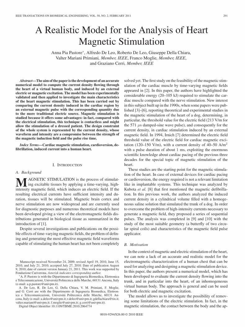
IEEE TRANSACTIONS ON BIOMEDICAL ENGINEERING, VOL. 58, NO. 2, FEBRUARY 2011 291
A Realistic Model for the Analysis of HeartMagnetic Stimulation
Anna Pia Pastore∗, Alfredo De Leo, Roberto De Leo, Giuseppe Della Chiara,Valter Mariani Primiani, Member, IEEE, Franco Moglie, Member, IEEE,
and Graziano Cerri, Member, IEEE
Abstract—The aim of the paper is the development of an accuratenumerical model to compute the current density flowing throughthe heart of a virtual human body, and induced by an externalelectric or magnetic excitation. The model has been experimentallyvalidated and then applied to investigate the main characteristicsof the heart magnetic stimulation. This has been carried out bycomparing the current density induced in the cardiac region byan external magnetic pulse with the corresponding quantity dueto the more traditional electric source. Magnetic stimulation isstudied because it offers some advantages: in fact, compared withthe electrical stimulation, this technique is contactless and mightallow the stimulation of a dressed patient. The design constraintof the whole system is represented by the current density, whosewaveform and intensity are a compromise between the strength ofthe magnetic induction field and the pulse rise time.
Index Terms—Cardiac magnetic stimulation, cardioversion, de-fibrillation, induced current into a human heart.
I. INTRODUCTION
A. Background
MAGNETIC STIMULATION is the process of stimulat-ing excitable tissues by applying a time-varying, high-
intensity magnetic field, which induces an electric field. If theresulting electrical currents have sufficient intensity and du-ration, tissues will be stimulated. Magnetic brain cortex andnerve stimulation are now widespread and are currently usedfor diagnostic purposes and numerous theoretical models havebeen developed giving a view of the electromagnetic fields dis-tributions generated in biological tissue as summarized in theintroduction of [1].
Despite several investigations and publications on the possi-ble effects of time-varying magnetic fields, the problem of defin-ing and generating the most effective magnetic field waveformscapable of stimulating the human heart has not been completely
Manuscript received November 24, 2009; revised April 19, 2010, June 15,2010, and July 21, 2010; accepted July 27, 2010. Date of publication August9, 2010; date of current version January 21, 2011. This work was supported byFondazione Cariverona. Asterisk indicates corresponding author.
∗A. P. Pastore is with the Dipartimento di Ingegneria Biomedica, Elettronicae Telecomunicazioni, Universita Politecnica delle Marche, 60131 Ancona, Italy(e-mail: [email protected]).
A. De Leo, R. De Leo, G. Della Chiara, V. M. Primiani, F. Moglie,and G. Cerri are with the Dipartimento di Ingegneria Biomedica, Elettron-ica e Telecomunicazioni, Universita Politecnica delle Marche, 60131 An-cona, Italy (e-mail: [email protected]; [email protected]; [email protected];[email protected]; [email protected]; [email protected]).
Digital Object Identifier 10.1109/TBME.2010.2064774
solved yet. The first study on the feasibility of the magnetic stim-ulation of the cardiac muscle by time-varying magnetic fieldsappeared in [2]. In this paper, the authors have highlighted theconsiderable energy (20–105 kJ) required to stimulate the car-diac muscle compared with the nerve stimulation. New interestin this subject built up in the 1990s, when some papers were pub-lished [3]–[6], reporting theoretical and experimental studies inthe magnetic stimulation of the heart of a dog, determining, inparticular, the threshold value for the electric field (213 V/m forthe 571 μs damped-sine wave pulse), and consequently for thecurrent density, in cardiac stimulation induced by an externalmagnetic field. In 1994, Irnich [7] determined the electric fieldthreshold value of the electric field for cardiac magnetic exci-tation (120–150 V/m), with a current density of 40–50 A/m2
with a pulse duration of about 1 ms, exploiting the enormousscientific knowledge about cardiac pacing of the previous threedecades for the special topic of magnetic stimulation of theheart.
These studies are the starting point for the magnetic stimula-tion of the heart. In case of external devices for cardiac pacingor cardioversion, the energy required is not a relevant limitationlike in implantable systems. This technique was analyzed byKubota et al. [8] that first mentioned the magnetic defibrilla-tion. In this previous work, the authors analyzed the inducedcurrent density in a cylindrical volume filled with a homoge-neous saline solution that simulated the trunk of a dog. In orderto overcome the problem of high-intensity currents necessary togenerate a magnetic field, they proposed a series of sequentialpulses. The analysis was completed in [9] and [10] with thestudy of the most suitable geometry (a butterfly of two circu-lar spiral coils) and characteristics of the magnetic field pulseapplicator.
B. Motivation
In the context of magnetic and electric stimulation of the heart,we can note a lack of an accurate and realistic model for theelectromagnetic characterization of a human chest that can beused for analyzing and designing a magnetic stimulation device.In this paper, the authors present a numerical model, which hasbeen developed to evaluate the current density flowing into thetrunk, and in particular into the heart, of an inhomogeneousvirtual human body. The approach is general and can be usedfor both electric and magnetic excitation.
The model allows us to investigate the possibility of remov-ing some limitations of the electric stimulation. In fact, in themagnetic stimulation, the contact between the body and the ap-
0018-9294/$26.00 © 2010 IEEE
292 IEEE TRANSACTIONS ON BIOMEDICAL ENGINEERING, VOL. 58, NO. 2, FEBRUARY 2011
Fig. 1. Geometry of the problem, coordinate system, and source representa-tion.
plicator is not required as in the electrical case, in which it isa critical constraint. This is due to the penetrability of humantissues to the magnetic field at low frequencies, which make thistechnique applicable to a dressed patient.
Based on the experience in the analysis of magnetic brainstimulation [11], and in the immunity tests of pacemakers [12],[13], we want to explore the possibility of the magnetic pulse tostimulate the cardiac region.
C. Aims of the Study
The availability of a model allows us to: 1) compare magneticand electric excitation; 2) analyze different shapes and positionsof the electrodes and coils; and 3) perform parametric studies.
The comparison between electric and magnetic stimulation isprobably the most important aspect, in the sense that magneticexcitation has to warrant the same performances provided by theelectric source in terms of current density in the cardiac region.The second aspect concerns essentially the conditions for theapplication of the stimulus, because its effectiveness stronglydepends on geometrical parameters. Moreover, the possibilityof carrying out parametric analysis is useful at a design stage,because the characterization of the induced current density interms of peak values, duration, and waveform will represent thedesign constraints of the whole system.
The numerical model has been experimentally validated bycomparing the results of the simulated current density with thecorresponding data measured in a saline solution of known con-ductivity.
The paper is organized as follows. Section II presents themodeling approach for both magnetic and electric stimulation.Section III addresses model validation through experiments.Section IV reports results for electric excitation and for magneticstimulation. In Section V, a general discussion of the obtainedresults is presented, and finally, the Section VI summarizes themain features of the work.
II. MODELING
A. Formulation of the Problem
The geometry of the problem is shown in Fig. 1, and repre-sents a source strongly coupled to a biological body.
The analytical solution of the problem is general, and bothelectric and magnetic excitation will be considered. In Fig. 1,circuit Γ is the magnetic source, in general a coil, where currentI0m is flowing. The electric source is modeled as current I0e ,which is directly injected into the body. Applying the procedurebriefly summarized in the following sections, the body is con-verted in a 3-D electrical network, and as a consequence, thefield problem is solved in terms of voltages and currents.
1) Magnetic Pulse Excitation: The electromagnetic prob-lem consists in the evaluation of the electric field and currentdensity distribution induced in biological tissues by an externalmagnetic pulse. The approach used to solve the electromagneticproblem stems from the impedance method proposed by Defordand Gandhi [14] for the study of biological bodies exposed tolow-frequency fields. The model has been properly modified byadding the inductive terms and considering the excitation termsin every branch of the grid.
The equation to be handled is the Faraday’s law in its integralform ∮
CS
E · dl = −jω
∫Sc
B · dS (1)
where B and E are total magnetic induction and electric field,respectively, in the body volume, J is the conduction currentdensity, and Cs is the boundary curve of the surface Sc .
The model is developed in the frequency domain, and time-domain results are achieved by applying an inverse fast Fouriertransform (FFT) algorithm. In order to separate the source con-tribution, the total magnetic induction is written as the sum of theexternal field B0 and the field scattered by the induced current(B(J)). Therefore, (1) becomes∮
CS
E · dl + jω
∫Sc
B0 · dS + jω
∫Sc
B(J) · dS = 0. (2)
Using the general relation∫Sc
B · dS =∮
CS
A · dl (3)
we can express the magnetic contributions in (2) in terms ofmagnetic vector potential∫
CS
(E + jωA0 + jωA
)· dl = 0 (4)
where referring to the coordinate system of Fig. 1
A0 (r) =∫
Γ
μI0m
(r′
)dl′
4π∣∣r − r′
∣∣ , A (r) =∫
V
μJ(r′
) ¯dV ′
4π∣∣r − r′
∣∣ (5)
I0m
(r′
)and ¯J
(r′
)being the source current and the induced cur-
rent density, respectively. Moreover, current density and electricfield are connected by the constitutive relation
J = σ(r)E + jωε0εr (r)E (6)
where σ(r) and εr (r) are the conductivity and relative per-mittivity in the volume. Even if the analyzed problem can beconsidered quasi-static, the displacement current is not negli-gible compared to the current driven by the induced electric
PASTORE et al.: REALISTIC MODEL FOR ANALYSIS OF HEART MAGNETIC STIMULATION 293
Fig. 2. (a) Local indexing system and current directions for the implemen-tation of the CKL. (b) Circuit parameters characterizing each branch of thenetwork: example of an x-directed current.
field, because of the high-permittivity values of the biologicaltissues [15].
A 3-D network is achieved after discretizing the volume in agrid of cubic cells of side: Δ = Δx = Δy = Δz, and applying(4) and (6) to each cell. Referring, for instance, to a single cubiccell, (4) represents the well-known voltage Kirchhoff law to beapplied to each face of the cube, Cs being an elementary meshof the 3-D network.
In this way, a distributed parameter problem is converted intoa lumped-element network. For computational purposes, it ismore convenient to express the solving system in terms of nodevoltages rather than branch current, and the impedance represen-tation allows us to express the nodes potential method (NPM) ina discrete form. The method consists of the implementation ofthe current Kirchhoff law (CKL) and expresses currents in termsof node potentials. In order to extend the analysis to the wholebody, a local indexing system is introduced [see Fig. 2(a)]. It ischaracterized by three integer values (i, j, k), which represent anode in the 3-D network, and by subscripts (x, y, z) that repre-sent the direction of a branch. Each branch is characterized byan impedance, current, and a voltage generator that takes intoaccount the external source: Fig. 2(b) shows an example of anx-directed branch. A similar circuital representation holds forall the branches oriented along other axes.
For computational purposes, we assume that physical quan-tities in (4) are constant along a branch of a cell, and therelation between the mesh current Ip and the current den-sity Jp is simply Jp = Ip/Δ2 , where p represents a genericbranch orientation (p = (x, y, z)). In order to show how thecircuit representation of the 3-D network is achieved, we ex-tracted, for example, the contribution of the x-directed branchin the mesh equation (4), and using notation of Fig. 2(b), weobtained the potential difference between nodes (i, j, k) and(i + 1, j, k)
∫ Δ
0(Ex + jωA0x + jωAx) dx = V(i,j,k) − V(i+1,j,k) . (7)
In (7), the driving electromotive force is defined as follows:
emfx,y ,z (i,j,k) = −jω
∫ Δ
0A0xdx (8)
where A0x is given by the first expression of (5) and representsthe known term of the equation. The inductive term is givenfrom (7) and the second expression of (5)∫ Δ
0Axdx ∼= AxΔ ∼=
μΔIx(i,j,k)
4π
∫ Δ
0
dx∣∣r − r′∣∣ = LIx(i,j,k) .
(9)Finally, inserting (6) in (7), the resistive and capacitive effect
is represented by∫ Δ
0Exdx ∼= Ex(i,j,k)Δ
=Ix(i,j,k)
σx,y ,z (i,j,k)Δ + jωε0εrx,y ,z (i,j,k)Δ. (10)
In (9), only the self-inductance is taken into account, whereasmutual coupling among cells is neglected because the externalmagnetic field is much greater than the scattered field. Inserting(8)–(10) in (7) and defining the impedance of the branch
Zx,y ,z (i,j,k) =1
σx,y ,z (i,j,k)Δ + jωε0εrx,y ,z (i,j,k)Δ+ jωL
(11)where L is the inductance of a conducting element with sideΔ [16]
L =μ0Δ√
2π(12)
we can express the current in a branch as follows:
Ix(i,j,k) =V(i,j,k) − V(i+1,j,k) + emfx(i,j,k)
Zx(i,j,k)(13)
and similarly for all the other branches.Introducing (13) in the node current balance
Ix(i,j,k) − Ix,(i−1,j,k) + Iy (i,j,k) − Iy,(i,j−1,k)
+ Iz (i,j,k) − Iz,(i,j,k−1) = 0 (14)
and considering all nodes, we obtain the solving linear system:
[Y ] [V ] = [I] (15)
where [Y ] is an admittance sparse matrix, whose nonzero ele-ments depend on the dielectric characteristics of the tissue andon the section of a single branch. [V ] is the unknown vector ofnode potentials and [I] is the known terms vector that dependson the currents of the magnetic source.
2) Electric Pulse Excitation: The presented model can workalso for electrical excitation: this situation is typical of cardiover-sion or defibrillation. The geometry is again described in Fig. 1,but the body is now excited by current I0e , injected and drainedthrough two surface regions. In this case, matrix Y is unchanged,whereas the excitation terms are zero, apart from the elements,which correspond to the contact points between the body and
294 IEEE TRANSACTIONS ON BIOMEDICAL ENGINEERING, VOL. 58, NO. 2, FEBRUARY 2011
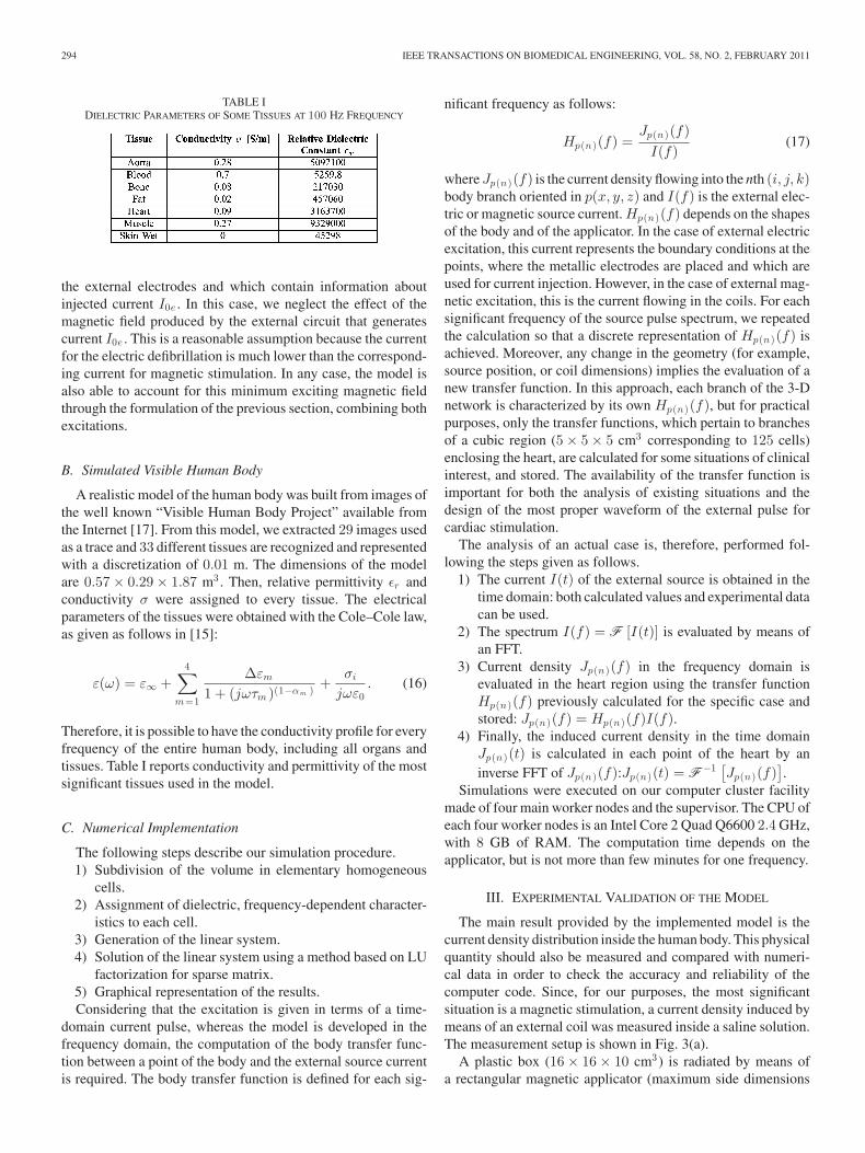
TABLE IDIELECTRIC PARAMETERS OF SOME TISSUES AT 100 HZ FREQUENCY
the external electrodes and which contain information aboutinjected current I0e . In this case, we neglect the effect of themagnetic field produced by the external circuit that generatescurrent I0e . This is a reasonable assumption because the currentfor the electric defibrillation is much lower than the correspond-ing current for magnetic stimulation. In any case, the model isalso able to account for this minimum exciting magnetic fieldthrough the formulation of the previous section, combining bothexcitations.
B. Simulated Visible Human Body
A realistic model of the human body was built from images ofthe well known “Visible Human Body Project” available fromthe Internet [17]. From this model, we extracted 29 images usedas a trace and 33 different tissues are recognized and representedwith a discretization of 0.01 m. The dimensions of the modelare 0.57 × 0.29 × 1.87 m3 . Then, relative permittivity εr andconductivity σ were assigned to every tissue. The electricalparameters of the tissues were obtained with the Cole–Cole law,as given as follows in [15]:
ε(ω) = ε∞ +4∑
m=1
Δεm
1 + (jωτm )(1−αm ) +σi
jωε0. (16)
Therefore, it is possible to have the conductivity profile for everyfrequency of the entire human body, including all organs andtissues. Table I reports conductivity and permittivity of the mostsignificant tissues used in the model.
C. Numerical Implementation
The following steps describe our simulation procedure.1) Subdivision of the volume in elementary homogeneous
cells.2) Assignment of dielectric, frequency-dependent character-
istics to each cell.3) Generation of the linear system.4) Solution of the linear system using a method based on LU
factorization for sparse matrix.5) Graphical representation of the results.Considering that the excitation is given in terms of a time-
domain current pulse, whereas the model is developed in thefrequency domain, the computation of the body transfer func-tion between a point of the body and the external source currentis required. The body transfer function is defined for each sig-
nificant frequency as follows:
Hp(n)(f) =Jp(n)(f)
I(f)(17)
where Jp(n)(f) is the current density flowing into the nth (i, j, k)body branch oriented in p(x, y, z) and I(f) is the external elec-tric or magnetic source current. Hp(n)(f) depends on the shapesof the body and of the applicator. In the case of external electricexcitation, this current represents the boundary conditions at thepoints, where the metallic electrodes are placed and which areused for current injection. However, in the case of external mag-netic excitation, this is the current flowing in the coils. For eachsignificant frequency of the source pulse spectrum, we repeatedthe calculation so that a discrete representation of Hp(n)(f) isachieved. Moreover, any change in the geometry (for example,source position, or coil dimensions) implies the evaluation of anew transfer function. In this approach, each branch of the 3-Dnetwork is characterized by its own Hp(n)(f), but for practicalpurposes, only the transfer functions, which pertain to branchesof a cubic region (5 × 5 × 5 cm3 corresponding to 125 cells)enclosing the heart, are calculated for some situations of clinicalinterest, and stored. The availability of the transfer function isimportant for both the analysis of existing situations and thedesign of the most proper waveform of the external pulse forcardiac stimulation.
The analysis of an actual case is, therefore, performed fol-lowing the steps given as follows.
1) The current I(t) of the external source is obtained in thetime domain: both calculated values and experimental datacan be used.
2) The spectrum I(f) = F [I(t)] is evaluated by means ofan FFT.
3) Current density Jp(n)(f) in the frequency domain isevaluated in the heart region using the transfer functionHp(n)(f) previously calculated for the specific case andstored: Jp(n)(f) = Hp(n)(f)I(f).
4) Finally, the induced current density in the time domainJp(n)(t) is calculated in each point of the heart by aninverse FFT of Jp(n)(f):Jp(n)(t) = F−1 [
Jp(n)(f)].
Simulations were executed on our computer cluster facilitymade of four main worker nodes and the supervisor. The CPU ofeach four worker nodes is an Intel Core 2 Quad Q6600 2.4 GHz,with 8 GB of RAM. The computation time depends on theapplicator, but is not more than few minutes for one frequency.
III. EXPERIMENTAL VALIDATION OF THE MODEL
The main result provided by the implemented model is thecurrent density distribution inside the human body. This physicalquantity should also be measured and compared with numeri-cal data in order to check the accuracy and reliability of thecomputer code. Since, for our purposes, the most significantsituation is a magnetic stimulation, a current density induced bymeans of an external coil was measured inside a saline solution.The measurement setup is shown in Fig. 3(a).
A plastic box (16 × 16 × 10 cm3) is radiated by means ofa rectangular magnetic applicator (maximum side dimensions
PASTORE et al.: REALISTIC MODEL FOR ANALYSIS OF HEART MAGNETIC STIMULATION 295
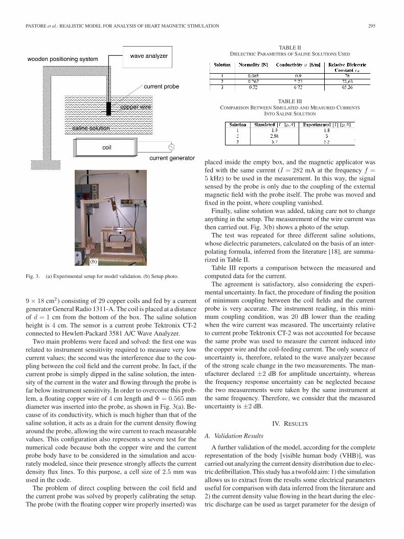
Fig. 3. (a) Experimental setup for model validation. (b) Setup photo.
9 × 18 cm2) consisting of 29 copper coils and fed by a currentgenerator General Radio 1311-A. The coil is placed at a distanceof d = 1 cm from the bottom of the box. The saline solutionheight is 4 cm. The sensor is a current probe Tektronix CT-2connected to Hewlett-Packard 3581 A/C Wave Analyzer.
Two main problems were faced and solved: the first one wasrelated to instrument sensitivity required to measure very lowcurrent values; the second was the interference due to the cou-pling between the coil field and the current probe. In fact, if thecurrent probe is simply dipped in the saline solution, the inten-sity of the current in the water and flowing through the probe isfar below instrument sensitivity. In order to overcome this prob-lem, a floating copper wire of 4 cm length and Φ = 0.565 mmdiameter was inserted into the probe, as shown in Fig. 3(a). Be-cause of its conductivity, which is much higher than that of thesaline solution, it acts as a drain for the current density flowingaround the probe, allowing the wire current to reach measurablevalues. This configuration also represents a severe test for thenumerical code because both the copper wire and the currentprobe body have to be considered in the simulation and accu-rately modeled, since their presence strongly affects the currentdensity flux lines. To this purpose, a cell size of 2.5 mm wasused in the code.
The problem of direct coupling between the coil field andthe current probe was solved by properly calibrating the setup.The probe (with the floating copper wire properly inserted) was
TABLE IIDIELECTRIC PARAMETERS OF SALINE SOLUTIONS USED
TABLE IIICOMPARISON BETWEEN SIMULATED AND MEASURED CURRENTS
INTO SALINE SOLUTION
placed inside the empty box, and the magnetic applicator wasfed with the same current (I = 282 mA at the frequency f =5 kHz) to be used in the measurement. In this way, the signalsensed by the probe is only due to the coupling of the externalmagnetic field with the probe itself. The probe was moved andfixed in the point, where coupling vanished.
Finally, saline solution was added, taking care not to changeanything in the setup. The measurement of the wire current wasthen carried out. Fig. 3(b) shows a photo of the setup.
The test was repeated for three different saline solutions,whose dielectric parameters, calculated on the basis of an inter-polating formula, inferred from the literature [18], are summa-rized in Table II.
Table III reports a comparison between the measured andcomputed data for the current.
The agreement is satisfactory, also considering the experi-mental uncertainty. In fact, the procedure of finding the positionof minimum coupling between the coil fields and the currentprobe is very accurate. The instrument reading, in this mini-mum coupling condition, was 20 dB lower than the readingwhen the wire current was measured. The uncertainty relativeto current probe Tektronix CT-2 was not accounted for becausethe same probe was used to measure the current induced intothe copper wire and the coil-feeding current. The only source ofuncertainty is, therefore, related to the wave analyzer becauseof the strong scale change in the two measurements. The man-ufacturer declared ±2 dB for amplitude uncertainty, whereasthe frequency response uncertainty can be neglected becausethe two measurements were taken by the same instrument atthe same frequency. Therefore, we consider that the measureduncertainty is ±2 dB.
IV. RESULTS
A. Validation Results
A further validation of the model, according for the completerepresentation of the body [visible human body (VHB)], wascarried out analyzing the current density distribution due to elec-tric defibrillation. This study has a twofold aim: 1) the simulationallows us to extract from the results some electrical parametersuseful for comparison with data inferred from the literature and2) the current density value flowing in the heart during the elec-tric discharge can be used as target parameter for the design of
296 IEEE TRANSACTIONS ON BIOMEDICAL ENGINEERING, VOL. 58, NO. 2, FEBRUARY 2011
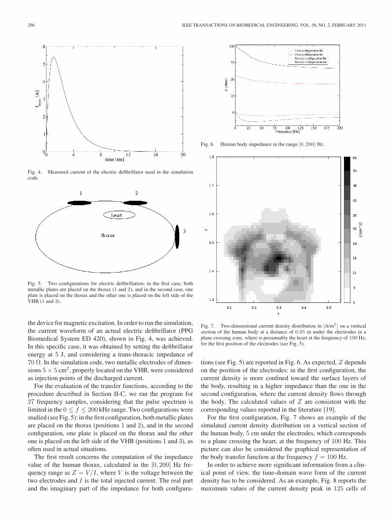
Fig. 4. Measured current of the electric defibrillator used in the simulationcode.
Fig. 5. Two configurations for electric defibrillation: in the first case, bothmetallic plates are placed on the thorax (1 and 2), and in the second case, oneplate is placed on the thorax and the other one is placed on the left side of theVHB (1 and 3).
the device for magnetic excitation. In order to run the simulation,the current waveform of an actual electric defibrillator (PPGBiomedical System ED 420), shown in Fig. 4, was achieved.In this specific case, it was obtained by setting the defibrillatorenergy at 5 J, and considering a trans-thoracic impedance of70 Ω. In the simulation code, two metallic electrodes of dimen-sions 5 × 5 cm2 , properly located on the VHB, were consideredas injection points of the discharged current.
For the evaluation of the transfer functions, according to theprocedure described in Section II-C, we ran the program for27 frequency samples, considering that the pulse spectrum islimited in the 0 ≤ f ≤ 200 kHz range. Two configurations werestudied (see Fig. 5): in the first configuration, both metallic platesare placed on the thorax (positions 1 and 2), and in the secondconfiguration, one plate is placed on the thorax and the otherone is placed on the left side of the VHB (positions 1 and 3), asoften used in actual situations.
The first result concerns the computation of the impedancevalue of the human thorax, calculated in the [0, 200] Hz fre-quency range as Z = V/I , where V is the voltage between thetwo electrodes and I is the total injected current. The real partand the imaginary part of the impedance for both configura-
Fig. 6. Human body impedance in the range [0, 200] Hz.
Fig. 7. Two-dimensional current density distribution in [A/m2 ] on a verticalsection of the human body at a distance of 0.05 m under the electrodes in aplane crossing zone, where is presumably the heart at the frequency of 100 Hz,for the first position of the electrodes (see Fig. 5).
tions (see Fig. 5) are reported in Fig. 6. As expected, Z dependson the position of the electrodes: in the first configuration, thecurrent density is more confined toward the surface layers ofthe body, resulting in a higher impedance than the one in thesecond configuration, where the current density flows throughthe body. The calculated values of Z are consistent with thecorresponding values reported in the literature [19].
For the first configuration, Fig. 7 shows an example of thesimulated current density distribution on a vertical section ofthe human body, 5 cm under the electrodes, which correspondsto a plane crossing the heart, at the frequency of 100 Hz. Thispicture can also be considered the graphical representation ofthe body transfer function at the frequency f = 100 Hz.
In order to achieve more significant information from a clin-ical point of view, the time-domain wave form of the currentdensity has to be considered. As an example, Fig. 8 reports themaximum values of the current density peak in 125 cells of
PASTORE et al.: REALISTIC MODEL FOR ANALYSIS OF HEART MAGNETIC STIMULATION 297
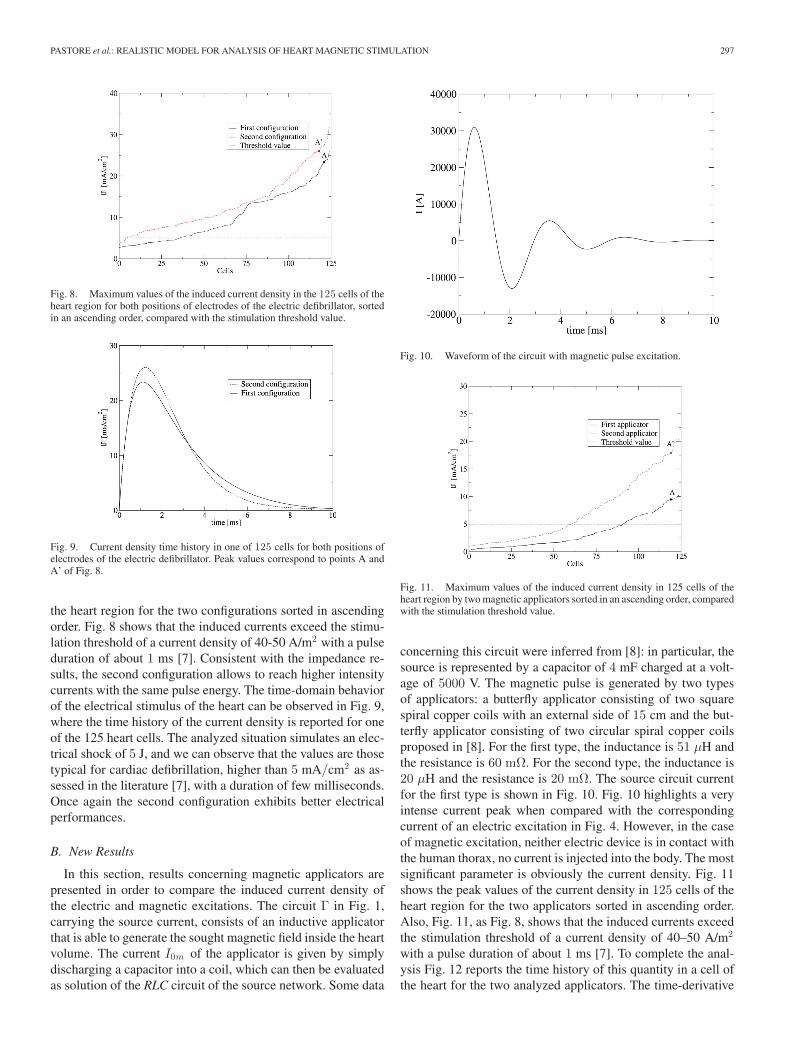
Fig. 8. Maximum values of the induced current density in the 125 cells of theheart region for both positions of electrodes of the electric defibrillator, sortedin an ascending order, compared with the stimulation threshold value.
Fig. 9. Current density time history in one of 125 cells for both positions ofelectrodes of the electric defibrillator. Peak values correspond to points A andA’ of Fig. 8.
the heart region for the two configurations sorted in ascendingorder. Fig. 8 shows that the induced currents exceed the stimu-lation threshold of a current density of 40-50 A/m2 with a pulseduration of about 1 ms [7]. Consistent with the impedance re-sults, the second configuration allows to reach higher intensitycurrents with the same pulse energy. The time-domain behaviorof the electrical stimulus of the heart can be observed in Fig. 9,where the time history of the current density is reported for oneof the 125 heart cells. The analyzed situation simulates an elec-trical shock of 5 J, and we can observe that the values are thosetypical for cardiac defibrillation, higher than 5 mA/cm2 as as-sessed in the literature [7], with a duration of few milliseconds.Once again the second configuration exhibits better electricalperformances.
B. New Results
In this section, results concerning magnetic applicators arepresented in order to compare the induced current density ofthe electric and magnetic excitations. The circuit Γ in Fig. 1,carrying the source current, consists of an inductive applicatorthat is able to generate the sought magnetic field inside the heartvolume. The current I0m of the applicator is given by simplydischarging a capacitor into a coil, which can then be evaluatedas solution of the RLC circuit of the source network. Some data
Fig. 10. Waveform of the circuit with magnetic pulse excitation.
Fig. 11. Maximum values of the induced current density in 125 cells of theheart region by two magnetic applicators sorted in an ascending order, comparedwith the stimulation threshold value.
concerning this circuit were inferred from [8]: in particular, thesource is represented by a capacitor of 4 mF charged at a volt-age of 5000 V. The magnetic pulse is generated by two typesof applicators: a butterfly applicator consisting of two squarespiral copper coils with an external side of 15 cm and the but-terfly applicator consisting of two circular spiral copper coilsproposed in [8]. For the first type, the inductance is 51 μH andthe resistance is 60 mΩ. For the second type, the inductance is20 μH and the resistance is 20 mΩ. The source circuit currentfor the first type is shown in Fig. 10. Fig. 10 highlights a veryintense current peak when compared with the correspondingcurrent of an electric excitation in Fig. 4. However, in the caseof magnetic excitation, neither electric device is in contact withthe human thorax, no current is injected into the body. The mostsignificant parameter is obviously the current density. Fig. 11shows the peak values of the current density in 125 cells of theheart region for the two applicators sorted in ascending order.Also, Fig. 11, as Fig. 8, shows that the induced currents exceedthe stimulation threshold of a current density of 40–50 A/m2
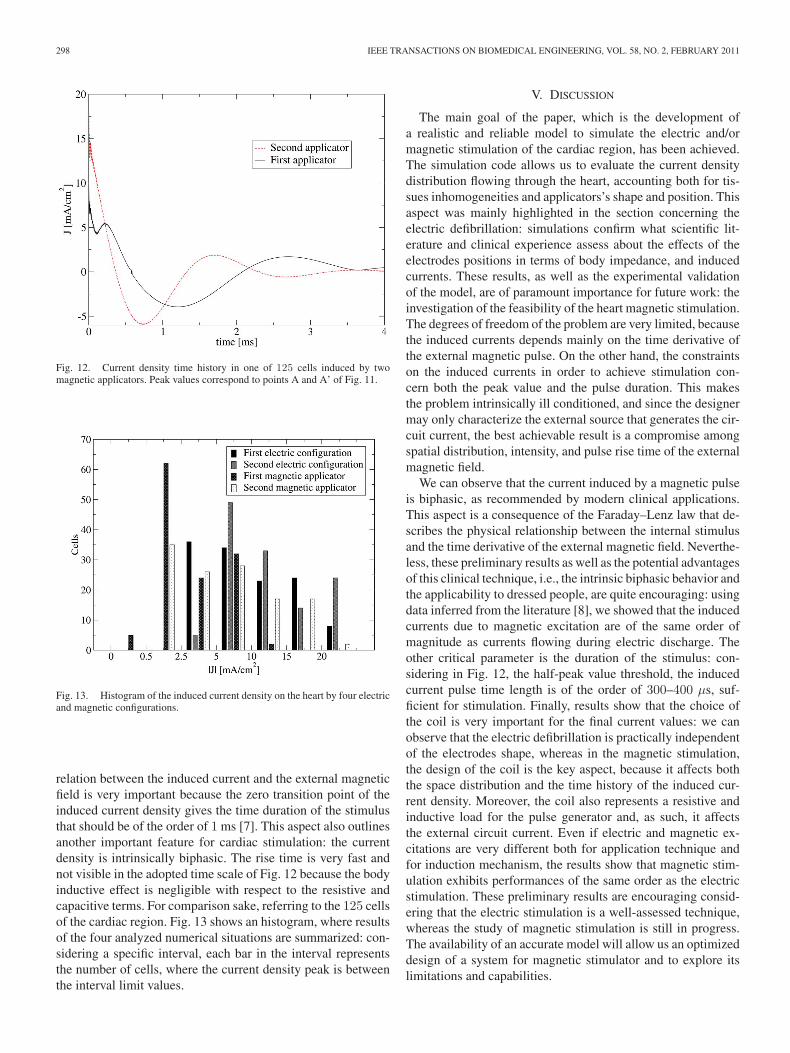
with a pulse duration of about 1 ms [7]. To complete the anal-ysis Fig. 12 reports the time history of this quantity in a cell ofthe heart for the two analyzed applicators. The time-derivative
298 IEEE TRANSACTIONS ON BIOMEDICAL ENGINEERING, VOL. 58, NO. 2, FEBRUARY 2011
Fig. 12. Current density time history in one of 125 cells induced by twomagnetic applicators. Peak values correspond to points A and A’ of Fig. 11.
Fig. 13. Histogram of the induced current density on the heart by four electricand magnetic configurations.
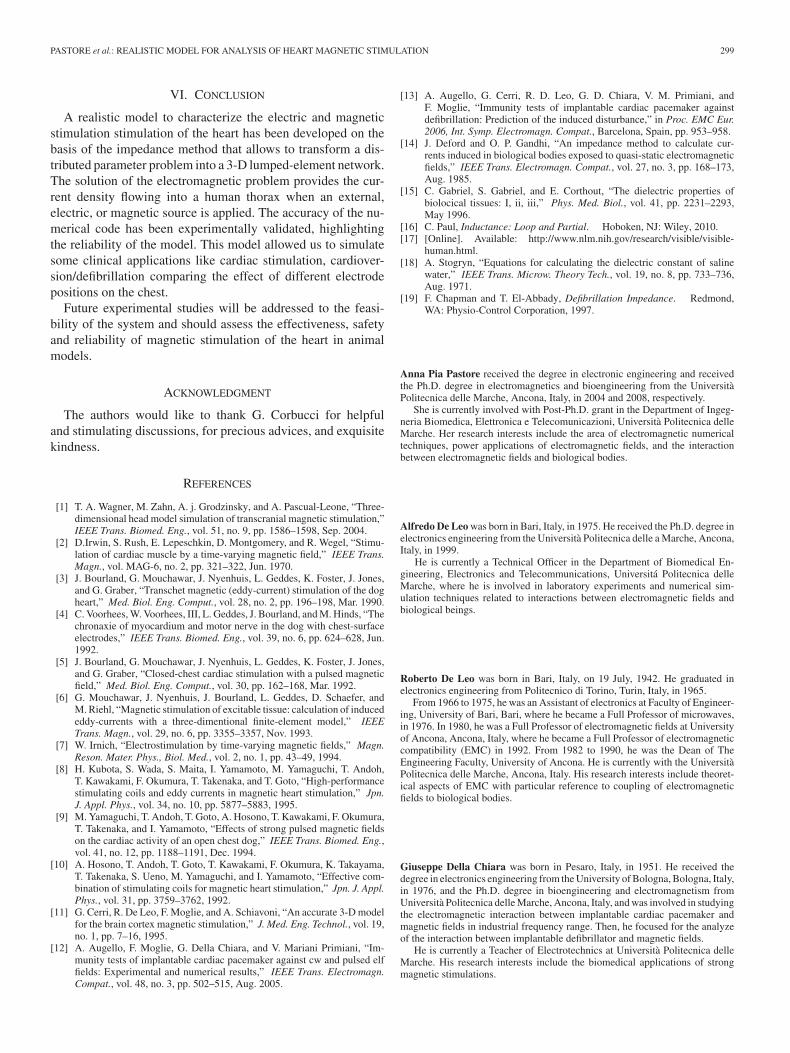
relation between the induced current and the external magneticfield is very important because the zero transition point of theinduced current density gives the time duration of the stimulusthat should be of the order of 1 ms [7]. This aspect also outlinesanother important feature for cardiac stimulation: the currentdensity is intrinsically biphasic. The rise time is very fast andnot visible in the adopted time scale of Fig. 12 because the bodyinductive effect is negligible with respect to the resistive andcapacitive terms. For comparison sake, referring to the 125 cellsof the cardiac region. Fig. 13 shows an histogram, where resultsof the four analyzed numerical situations are summarized: con-sidering a specific interval, each bar in the interval representsthe number of cells, where the current density peak is betweenthe interval limit values.
V. DISCUSSION
The main goal of the paper, which is the development ofa realistic and reliable model to simulate the electric and/ormagnetic stimulation of the cardiac region, has been achieved.The simulation code allows us to evaluate the current densitydistribution flowing through the heart, accounting both for tis-sues inhomogeneities and applicators’s shape and position. Thisaspect was mainly highlighted in the section concerning theelectric defibrillation: simulations confirm what scientific lit-erature and clinical experience assess about the effects of theelectrodes positions in terms of body impedance, and inducedcurrents. These results, as well as the experimental validationof the model, are of paramount importance for future work: theinvestigation of the feasibility of the heart magnetic stimulation.The degrees of freedom of the problem are very limited, becausethe induced currents depends mainly on the time derivative ofthe external magnetic pulse. On the other hand, the constraintson the induced currents in order to achieve stimulation con-cern both the peak value and the pulse duration. This makesthe problem intrinsically ill conditioned, and since the designermay only characterize the external source that generates the cir-cuit current, the best achievable result is a compromise amongspatial distribution, intensity, and pulse rise time of the externalmagnetic field.
We can observe that the current induced by a magnetic pulseis biphasic, as recommended by modern clinical applications.This aspect is a consequence of the Faraday–Lenz law that de-scribes the physical relationship between the internal stimulusand the time derivative of the external magnetic field. Neverthe-less, these preliminary results as well as the potential advantagesof this clinical technique, i.e., the intrinsic biphasic behavior andthe applicability to dressed people, are quite encouraging: usingdata inferred from the literature [8], we showed that the inducedcurrents due to magnetic excitation are of the same order ofmagnitude as currents flowing during electric discharge. Theother critical parameter is the duration of the stimulus: con-sidering in Fig. 12, the half-peak value threshold, the inducedcurrent pulse time length is of the order of 300–400 μs, suf-ficient for stimulation. Finally, results show that the choice ofthe coil is very important for the final current values: we canobserve that the electric defibrillation is practically independentof the electrodes shape, whereas in the magnetic stimulation,the design of the coil is the key aspect, because it affects boththe space distribution and the time history of the induced cur-rent density. Moreover, the coil also represents a resistive andinductive load for the pulse generator and, as such, it affectsthe external circuit current. Even if electric and magnetic ex-citations are very different both for application technique andfor induction mechanism, the results show that magnetic stim-ulation exhibits performances of the same order as the electricstimulation. These preliminary results are encouraging consid-ering that the electric stimulation is a well-assessed technique,whereas the study of magnetic stimulation is still in progress.The availability of an accurate model will allow us an optimizeddesign of a system for magnetic stimulator and to explore itslimitations and capabilities.
PASTORE et al.: REALISTIC MODEL FOR ANALYSIS OF HEART MAGNETIC STIMULATION 299
VI. CONCLUSION
A realistic model to characterize the electric and magneticstimulation stimulation of the heart has been developed on thebasis of the impedance method that allows to transform a dis-tributed parameter problem into a 3-D lumped-element network.The solution of the electromagnetic problem provides the cur-rent density flowing into a human thorax when an external,electric, or magnetic source is applied. The accuracy of the nu-merical code has been experimentally validated, highlightingthe reliability of the model. This model allowed us to simulatesome clinical applications like cardiac stimulation, cardiover-sion/defibrillation comparing the effect of different electrodepositions on the chest.
Future experimental studies will be addressed to the feasi-bility of the system and should assess the effectiveness, safetyand reliability of magnetic stimulation of the heart in animalmodels.
ACKNOWLEDGMENT
The authors would like to thank G. Corbucci for helpfuland stimulating discussions, for precious advices, and exquisitekindness.
REFERENCES
[1] T. A. Wagner, M. Zahn, A. j. Grodzinsky, and A. Pascual-Leone, “Three-dimensional head model simulation of transcranial magnetic stimulation,”IEEE Trans. Biomed. Eng., vol. 51, no. 9, pp. 1586–1598, Sep. 2004.
[2] D.Irwin, S. Rush, E. Lepeschkin, D. Montgomery, and R. Wegel, “Stimu-lation of cardiac muscle by a time-varying magnetic field,” IEEE Trans.Magn., vol. MAG-6, no. 2, pp. 321–322, Jun. 1970.
[3] J. Bourland, G. Mouchawar, J. Nyenhuis, L. Geddes, K. Foster, J. Jones,and G. Graber, “Transchet magnetic (eddy-current) stimulation of the dogheart,” Med. Biol. Eng. Comput., vol. 28, no. 2, pp. 196–198, Mar. 1990.
[4] C. Voorhees, W. Voorhees, III, L. Geddes, J. Bourland, and M. Hinds, “Thechronaxie of myocardium and motor nerve in the dog with chest-surfaceelectrodes,” IEEE Trans. Biomed. Eng., vol. 39, no. 6, pp. 624–628, Jun.1992.
[5] J. Bourland, G. Mouchawar, J. Nyenhuis, L. Geddes, K. Foster, J. Jones,and G. Graber, “Closed-chest cardiac stimulation with a pulsed magneticfield,” Med. Biol. Eng. Comput., vol. 30, pp. 162–168, Mar. 1992.
[6] G. Mouchawar, J. Nyenhuis, J. Bourland, L. Geddes, D. Schaefer, andM. Riehl, “Magnetic stimulation of excitable tissue: calculation of inducededdy-currents with a three-dimentional finite-element model,” IEEETrans. Magn., vol. 29, no. 6, pp. 3355–3357, Nov. 1993.
[7] W. Irnich, “Electrostimulation by time-varying magnetic fields,” Magn.Reson. Mater. Phys., Biol. Med., vol. 2, no. 1, pp. 43–49, 1994.
[8] H. Kubota, S. Wada, S. Maita, I. Yamamoto, M. Yamaguchi, T. Andoh,T. Kawakami, F. Okumura, T. Takenaka, and T. Goto, “High-performancestimulating coils and eddy currents in magnetic heart stimulation,” Jpn.J. Appl. Phys., vol. 34, no. 10, pp. 5877–5883, 1995.
[9] M. Yamaguchi, T. Andoh, T. Goto, A. Hosono, T. Kawakami, F. Okumura,T. Takenaka, and I. Yamamoto, “Effects of strong pulsed magnetic fieldson the cardiac activity of an open chest dog,” IEEE Trans. Biomed. Eng.,vol. 41, no. 12, pp. 1188–1191, Dec. 1994.
[10] A. Hosono, T. Andoh, T. Goto, T. Kawakami, F. Okumura, K. Takayama,T. Takenaka, S. Ueno, M. Yamaguchi, and I. Yamamoto, “Effective com-bination of stimulating coils for magnetic heart stimulation,” Jpn. J. Appl.Phys., vol. 31, pp. 3759–3762, 1992.
[11] G. Cerri, R. De Leo, F. Moglie, and A. Schiavoni, “An accurate 3-D modelfor the brain cortex magnetic stimulation,” J. Med. Eng. Technol., vol. 19,no. 1, pp. 7–16, 1995.
[12] A. Augello, F. Moglie, G. Della Chiara, and V. Mariani Primiani, “Im-munity tests of implantable cardiac pacemaker against cw and pulsed elffields: Experimental and numerical results,” IEEE Trans. Electromagn.Compat., vol. 48, no. 3, pp. 502–515, Aug. 2005.
[13] A. Augello, G. Cerri, R. D. Leo, G. D. Chiara, V. M. Primiani, andF. Moglie, “Immunity tests of implantable cardiac pacemaker againstdefibrillation: Prediction of the induced disturbance,” in Proc. EMC Eur.2006, Int. Symp. Electromagn. Compat., Barcelona, Spain, pp. 953–958.
[14] J. Deford and O. P. Gandhi, “An impedance method to calculate cur-rents induced in biological bodies exposed to quasi-static electromagneticfields,” IEEE Trans. Electromagn. Compat., vol. 27, no. 3, pp. 168–173,Aug. 1985.
[15] C. Gabriel, S. Gabriel, and E. Corthout, “The dielectric properties ofbiolocical tissues: I, ii, iii,” Phys. Med. Biol., vol. 41, pp. 2231–2293,May 1996.
[16] C. Paul, Inductance: Loop and Partial. Hoboken, NJ: Wiley, 2010.[17] [Online]. Available: http://www.nlm.nih.gov/research/visible/visible-
human.html.[18] A. Stogryn, “Equations for calculating the dielectric constant of saline
water,” IEEE Trans. Microw. Theory Tech., vol. 19, no. 8, pp. 733–736,Aug. 1971.
[19] F. Chapman and T. El-Abbady, Defibrillation Impedance. Redmond,WA: Physio-Control Corporation, 1997.
Anna Pia Pastore received the degree in electronic engineering and receivedthe Ph.D. degree in electromagnetics and bioengineering from the UniversitaPolitecnica delle Marche, Ancona, Italy, in 2004 and 2008, respectively.
She is currently involved with Post-Ph.D. grant in the Department of Ingeg-neria Biomedica, Elettronica e Telecomunicazioni, Universita Politecnica delleMarche. Her research interests include the area of electromagnetic numericaltechniques, power applications of electromagnetic fields, and the interactionbetween electromagnetic fields and biological bodies.
Alfredo De Leo was born in Bari, Italy, in 1975. He received the Ph.D. degree inelectronics engineering from the Universita Politecnica delle a Marche, Ancona,Italy, in 1999.
He is currently a Technical Officer in the Department of Biomedical En-gineering, Electronics and Telecommunications, Universita Politecnica delleMarche, where he is involved in laboratory experiments and numerical sim-ulation techniques related to interactions between electromagnetic fields andbiological beings.
Roberto De Leo was born in Bari, Italy, on 19 July, 1942. He graduated inelectronics engineering from Politecnico di Torino, Turin, Italy, in 1965.
From 1966 to 1975, he was an Assistant of electronics at Faculty of Engineer-ing, University of Bari, Bari, where he became a Full Professor of microwaves,in 1976. In 1980, he was a Full Professor of electromagnetic fields at Universityof Ancona, Ancona, Italy, where he became a Full Professor of electromagneticcompatibility (EMC) in 1992. From 1982 to 1990, he was the Dean of TheEngineering Faculty, University of Ancona. He is currently with the UniversitaPolitecnica delle Marche, Ancona, Italy. His research interests include theoret-ical aspects of EMC with particular reference to coupling of electromagneticfields to biological bodies.
Giuseppe Della Chiara was born in Pesaro, Italy, in 1951. He received thedegree in electronics engineering from the University of Bologna, Bologna, Italy,in 1976, and the Ph.D. degree in bioengineering and electromagnetism fromUniversita Politecnica delle Marche, Ancona, Italy, and was involved in studyingthe electromagnetic interaction between implantable cardiac pacemaker andmagnetic fields in industrial frequency range. Then, he focused for the analyzeof the interaction between implantable defibrillator and magnetic fields.
He is currently a Teacher of Electrotechnics at Universita Politecnica delleMarche. His research interests include the biomedical applications of strongmagnetic stimulations.
300 IEEE TRANSACTIONS ON BIOMEDICAL ENGINEERING, VOL. 58, NO. 2, FEBRUARY 2011
Valter Mariani Primiani (M’93) was born in Rome, Italy, in 1961. He receivedthe Dr. Ing. degree in electronics engineering from the Universita Politecnicadelle Marche, Ancona, Italy, in 1990.
He is currently an Associate Professor in electromagnetic compatibility(EMC) at the Universita Politecnica delle Marche, where he is a member of theDepartment of Biomedical, Electronic, and Telecommunications Engineering(DIBET) and is responsible for the EMC laboratory.
Prof. Primiani is a member of IEEE EMC Society, IEEE IM Society, and theItalian Electromagnetics Society.
Franco Moglie (M’91) was born in Ancona, Italy, in 1961. He received theDr. Ing. degree in electronics engineering from the Universita Politecnica delleMarche, Ancona, in 1986, and the Ph.D. degree in electronics engineering andelectromagnetics curriculum from the University of Bari, Bari, Italy, in 1992.
In 1986, he was a tenured Researcher in the Dipartimento di Elettronica edAutomatica, Universita Politecnica delle Marche, where he has been with theDIBET since 2008.
Mr. Moglie is member of the IEEE Electromagnetic Compatibility Societyand the Electromagnetic Italian Society.
Graziano Cerri (M’92) received the degree in electrical engineering from Uni-versita Politecnica delle Marche, Ancana, Italy, in 1981.
He is currently a Full Professor of electromagnetic fields in the Departmentof Bioengineering, Electronics and Telecommunications, Universita Politec-nica delle Marche. His research interests include electomagnetic compatability(EMC) problems, the analysis of the interaction between EM fields and bio-logical bodies, and plasma antennas. Since 2004, he has been a Director ofInteruniversity Italian Center for the study of the interactions between electro-magnetic fields and biosystems.
Prof. Cerri is a member of the Administrative and Scientific Board of In-teruniversity Italian Research Centre for EMC, and a member of the ScientificBoard of Italian Association of Electromagnetics. Since 2006, he has also beena member of the steering committee of the EMC-Europe International Sympo-sium on Electromagnetic Compatibility.
Copyright © 2022 FDOKUMEN