A proposed standards-based approach for representing heterogeneous objects for layered manufacturing
26
A proposed ISO 10303 (STEP)-based approach for representing heterogeneous objects for layered manufacturing Lalit Patil and Debasish Dutta Department of Mechanical Engineering University of Michigan, Ann Arbor, MI. USA. Email: [lpatil/dutta]@engin.umich.edu A. D. Bhatt, K. Jurrens, K. Lyons, M.J. Pratt and R.D. Sriram National Institute of Standards and Technology, Gaithersburg, MD. USA. Email: [abhatt/kjurrens/klyons/pratt/sriram]@nist.gov Abstract Solid modeling of objects forms an important task in design and manufacturing. Recent developments in the field of layered manufacturing (LM) have shown potential for the physical realization of heterogeneous (multi-material) objects. Thus, there is a need to represent material information as an integral part of the CAD model data. Slicing of the CAD model is an inherent part of process planning for LM. There is a need for a neutral 2D slice format to transfer data from the CAD system (slicing is done on the 3D CAD model) to the commercial LM machine. This can also be used as a file format to demonstrate inter-operability among LM machines having comparable layer thickness specifications. To fabricate heterogeneous objects, the slice format should be capable of representing both material and geometry information. Information models for the representation of product data are being developed as an international standard (ISO 10303) informally called STEP. However, the current application protocols focus on the representation of homogeneous objects only. This paper suggests an information model to represent heterogeneous objects using the in- formation modeling methodology developed for ISO 10303. The information model Address all correspondence to this author 1
-
Upload
independent -
Category
Documents
-
view
1 -
download
0
Transcript of A proposed standards-based approach for representing heterogeneous objects for layered manufacturing
A proposed ISO 10303 (STEP)-based approachfor representing heterogeneous objects for
layered manufacturing
Lalit Patil andDebasishDutta�
Departmentof MechanicalEngineering
Universityof Michigan,Ann Arbor, MI. USA.
Email: [lpatil/dutta]@engin.umich.edu
A. D. Bhatt,K. Jurrens,K. Lyons,M.J.Prattand R.D.SriramNationalInstituteof StandardsandTechnology, Gaithersburg, MD. USA.
Email: [abhatt/kjurrens/klyons/pratt/sriram]@nist.gov
Abstract
Solid modelingof objectsforms an importanttaskin designandmanufacturing.
Recentdevelopmentsin thefield of layeredmanufacturing(LM) haveshown potential
for thephysicalrealizationof heterogeneous(multi-material)objects.Thus,thereis a
needto representmaterialinformationasanintegral partof theCAD modeldata.
Slicingof theCAD modelis aninherentpartof processplanningfor LM. Thereis
a needfor a neutral2D slice formatto transferdatafrom theCAD system(slicing is
doneonthe3D CAD model)to thecommercialLM machine.Thiscanalsobeusedas
afile formatto demonstrateinter-operabilityamongLM machineshaving comparable
layer thicknessspecifications.To fabricateheterogeneousobjects,the slice format
shouldbecapableof representingbothmaterialandgeometryinformation.
Informationmodelsfor therepresentationof productdataarebeingdevelopedas
an internationalstandard(ISO 10303)informally calledSTEP. However, thecurrent
applicationprotocolsfocuson therepresentationof homogeneousobjectsonly. This
papersuggestsaninformationmodelto representheterogeneousobjectsusingthein-
formationmodelingmethodologydevelopedfor ISO 10303. The informationmodel�Addressall correspondenceto thisauthor
1
is thenextendedto representthe2D sliceinformationusingconceptsfrom ISO10303.
Theproposedformatsarevalidatedby physicalrealizationof objectsondifferentLM
machines.This informationmodelwill helpin providing auniformbasein thedevel-
opmentof heterogeneoussolidmodelingsystems.It will alsoequipthesolidmodeler
with theability to integratewith otherapplicationsandprocessplanningin thedomain
of layeredmanufacturing.
1 Introduction
Layeredmanufacturing/ rapidprototyping,alsoknownassolidfreeformfabrication(SFF),
is anadditivemanufacturingprocessin whichobjectsareconstructedby depositionof ma-
terial in layers,usually in termsof a sequenceof parallelplanarlaminae. Many layered
manufacturing(LM) processeshave beendevelopedin recentyears,usingdifferentma-
terialsandbondingmethods.Although LM wasoriginally usedfor rapid prototypingto
help the designerverify part form andfit (geometry),it is now progressingtowardsthe
productionof functionalparts. It hasalsoshown significantpotentialfor themanufacture
of uniqueandsmallbatchproductionparts.
Until recently, the domainof solid modelingfocusedmainly on modelingof solids
to capturegeometryand topology of external and internal features. Information about
materialgradationhasnot beenan integral part of the ComputerAided Design(CAD)
modeldata. Thus,all down-line processplanningassumesthepresenceof homogeneous
materialdistributionthroughouttheinteriorof thesolid.
The exigenciesof optimal designspecify the needfor functionally gradedor non-
homogeneousmaterialcompositions.Theseheterogeneousobjectsarecomposedof differ-
entconstituentmaterialsandcanexhibit continuouslyvaryingcompositionand/ormicro-
structure,thusproducinga gradationin theirproperties[1]. Dueto its additivenature,LM
is well suitedto the fabricationof heterogeneousobjects.It candepositseveralmaterials
in varyingcompositionswithin a layerandwith variationsbetweenadjacentlayers.
Heterogeneousobjectshave foundusein severalengineeringapplications.Therefore,
thereis a needto beableto designandmanufactureheterogeneousobjects[1]. However,
2
currentlytheredoesnotexist thecapabilityto createa three-dimensional(3D) CAD model
thatcanrepresentaproduct’ssolid interior, in termsof continuouslyvaryingmaterialcom-
positions.It is expectedthat thedevelopmentof a representationsuitablefor this areacan
alsobe appliedto representcolor, porosity, andotherpropertiesthat have gradientchar-
acteristics.Someof the reasonsthat make sucha representationessentialin the design
domainareasfollows:
� All LM technologiesarecomputerbasedandusetheCAD modelfor thepurposeof
processplanningandfabricationof thepart.
� Orientationof an object to be fabricatedwill dependon materialcompositionand
variationin aparticulardirectionandacrossacross-sectionaswell.
� Slicingcalculationswill requirematerialinformationbecausetheminimumandmax-
imumallowedlayerthicknessesvarywith differentmaterials.
� Applicationsfor analysis(thermal,structural,etc.) will requiresuchinformationto
beincorporatedin theCAD modelitself.
Slicing is an inherentpart of the processof LM. However, slicing maybestbedone
in theCAD systemon the3D solid modelitself [2]. Theneedfor a neutralformatfor the
purposeof slice informationis presentedin [2]. Sucha formatshouldencapsulateexact,
ratherthanfacetedgeometricinformation.Thereis no defactostandardto representsuch
sliceinformation.With theadventof LM techniquestomanufactureheterogeneousobjects,
the neutralformat shouldalso be able to representboth the materialand the geometry
informationin the2D slicedomain.
Thus,theabsenceof representationsto integratematerialandgeometryinformationat
thedesignstagewill hindernew developmentsin LM technologyaskey processplanning
stepsdependonsucharepresentation.A standardinformationmodelfor thisrepresentation
is requiredto realizethefollowing objectives:
� Provideauniformbaseto developheterogeneoussolidmodelingsystems.
3

� Transferof datain a standardformatamongvariousCAD/CAE systemssuchthatit
canbeusedefficiently for theengineeringanalysisandprocessplanningin theLM
environment.
ISO10303(informally known asSTEP)is aninternationalstandardfor theelectronic
exchangeof productdatabetweencomputeraideddesignandothercomputer-basedsys-
temsusedin theproductlife-cycle. This paperfocuseson anaspectof therepresentation
of heterogeneousobjects,andutilizesamodelingmethodologysuitablefor possibleusein
theapplicationof STEPto layeredmanufacturing.
This paperis built uponthe work reportedin [3]. This work focusedon the devel-
opmentof an IS0 10303representationschemefor heterogeneoussolids. However, an
informationmodelto representheterogeneousslicesis necessarybecauseslicing formsa
fundamentalstepin theprocessplanningfor LM [2]. A slice level representationis also
a meansto validatethe3D representationby fabricationof physicalparts.This paperalso
presentsadataplanningmodelto representslicelevel information.It furtherreportsdevel-
opmentof softwareto convert theslicerepresentationfile to machine-specificsliceformats
sothatexamplepartscanbephysicallyfabricatedoncommercialmachines.
Section2 presentsa brief review of variousapproachesfor heterogeneoussolid rep-
resentationandconsidersoneof themfor elaborationin subsequentsections.Section3
focuseson themotivationto useSTEPfor sucha representation.Detailsof theproposed
informationmodelsarediscussedat two levels (solid level andslice level) in Section4.
Validationof theproposeddataplanningmodels(DPM) is presentedin Sections5 and6.
Thepaperconcludeswith someobservationsandissuesfor futureresearch.
2 Heterogeneous solid modeling schemes
Heterogeneoussolid modelingaimsto incorporateinformationaboutmaterialdistribution
alongwith geometricinformationinto a CAD model.This necessitatesthedefinitionof a
function thatcanrepresentthematerialmacrostructure.This sectionsummarizesvarious
researchefforts in modelingheterogeneousobjects.
4
Irregular tetrahedral decompositionsof the finite elementtype provide possibilities
for modelingof materialdistributions. A solid modelcreatedon a state-of-the-artCAD
systemis meshedinto finite elements(tetrahedra).The topologyis maintainedusingthe
cell-tuplestructureasagraphof cells.Everycell is thenassociatedwith informationabout
thecompositionandthegeometry. Materialspaceis definedasM, spanningthedm mate-
rials availableto theLM machine.Thematerialcompositionof themodelis represented
asavectorvaluedfunctionm�x� definedover theinteriorof themodel.Thedesignerspec-
ifies theoverall variationin termsof distancefrom a particularfeature.This expressionis
usedto obtainthe volumefractionsat the verticesof eachtetrahedron.The composition
in the interior of the cell is thenobtainedin termsof a setof control pointsandcontrol
compositionsblendedwith barycentricBernsteinpolynomials.Representingobjectsusing
thisstrategy is thesubjectof [4].
Voxelbasedrepresentationis a specialcaseof cell decomposition.Thecell is cubical
in shapeandis locatedin a fixedgrid. A voxel (x,y,z) in a 3D discretespaceis definedby
a unit cubecenteredat (x,y,z). Voxelizationis the processof convertinga geometrically
represented3D objectinto a voxel modeldefinedby a setof voxels. Thevoxelizationis
suchthat thevoxel sizeis uniform andevery voxel is smallenoughto beconsideredasa
homogeneouslump. A scalarvalueassociatedwith everyvoxel indicatesthematerialthatis
associatedwith thatvoxel. Voxelizationis independentof thematerialdistributionfunction.
This representationallowsthedesignerto selectively assignmaterialsto individualvoxels.
Moredetailson this representationcanbefoundin [5].
TheR-functionmethodinterpolatesboundaryconditionsdirectly from thegeometric
modelusingnormalizedfunctions. Normalizedfunctionsaresmoothfunctionsthat ap-
proximatedistancefunctionsin theneighborhoodof theboundaryandcanbeconstructed
automaticallyfrom mostgeometricrepresentations(e.g. boundaryrepresentation)using
thetheoryof R-functions.More detailon this theorycanbeobtainedfrom [6]. This the-
ory appearsto have thepotentialto representthevariationof materialcompositionin the
interiorof asolid.
Along with theabove,severalotherschemesarebeingproposedfor therepresentation
of heterogeneousobjects[7, 8].
5
Therm objectmodelis a setbasedapproachto representmulti-materialobjects.It is
basedon exactrepresentationof geometryandassociatinga materialdistribution function
with thisgeometry. TheproductspaceT � E3 � Rn formsthemathematicalspaceto model
heterogeneousobjects.Materialpointsarerestrictedto lie in thematerialspaceV � Rn.
Eachpoint p in theobjectS is acombinationof n primarymaterialsandis specifiedby the
volumefractionsof theseprimary materials.Thesevolumefractionsmustsumto unity.
Thus,eachpoint p � S canbe modeledasa point (x � E3 v � V) in T, wherex andv
representthe geometricandmaterialpointsrespectively. This approachis basedon the
notionof anrm setwhichis definedasasubsetD �P B� of T whereP � E3 is anr-set[9]
andB � V assignsmaterialto ther-setP. ThesetB is specifiedby a materialfunctionF
which is requiredto beC∞. Thus,anrm setcanalsobedefinedasthepair (P F) wherethe
subsetB is definedimplicitly throughits materialfunctionasF�P� . To representaphysical
object,anrm-objectis thendefinedasa finite collectionof rm-sets{( Pj B j )} suchthat the
rm-setsareminimal andaregeometricallyinterior-disjoint. More detailson this approach
canbeobtainedin [1].
HeterogeneousSolid Modeling is an importantnew topic that is receiving increased
attention.Our brief survey wasnot intendedto beexhaustive andthe interestedreaderis
urgedto delve into thereferencesfor moredetailsandfurtherliteratureon thisandrelated
topics.
Thefocusof this paperis not therepresentationof heterogeneousobjectsperse. In-
steadwe considerone representationschemefor heterogeneousobjectsand investigate
extensionsnecessarywithin ISO 10303(STEP)for supportingit. While all representation
methodsstudiedabove have their advantagesanddisadvantages,we chosethe rm-object
modelapproachsincewe aremostfamiliar with it. In theremainderof this paper, all dis-
cussionaboutheterogeneoussolidrepresentationsandSTEPextensionsis in thecontext of
thisscheme.
6
3 Motivation for the use of ISO 10303
Informationaboutexactgeometry, materialsandtheirdistribution,andtolerancesneedsto
berepresentedandexchangedin computer-compatibleformat.A detailedstudyof existing
standardsfor representingobjectsin LM anddataformatsfor exchangingmodelinforma-
tion in thedomainof LayeredManufacturinghasbeenpresentedin [2, 10].
The needto representandmanufactureheterogeneoussolidscoupledwith the pos-
sibility that somestagesof processplanningmay migrateinto the CAD domainleadsto
thenecessityof developmentof a standarddatarepresentationfor layeredmanufacturing.
Thereis amplejustificationfor thesuitabilityof ISO10303for thispurpose[2, 10,11].
ISO 10303 (STEP)
ISO 10303(informally known asSTEP- STandardfor the Exchangeof Productmodel
data)is anevolving internationalstandardfor thecomputer-interpretablerepresentationand
exchangeof productdatafor engineeringpurposes.Thenatureof thisdescriptionmakesit
suitablefor neutralfile exchange,andalsoasabasisfor implementingandsharingproduct
databases[12].
ISO 10303is intendedultimately to cover a wide rangeof producttypesandprod-
uct life-cycle stages.It is beingissuedasa seriesof parts,includingGenericResources,
DescriptionMethods,ImplementationMethodsandApplicationProtocols(APs). APsare
complex datamodelsusedto describespecificproduct-dataapplicationsand are meant
to be implementable.Thesepartsdescribenot only what datais to be usedin describ-
ing a product,but alsohow the datais to beusedin the model. Thusactualinformation
exchangesarebasedon theapplicationprotocols.
Currently, thereis no STEPAP in theareaof LM. However, following severalmeet-
ings of an informal interestgroup, a formal projecthasbeenrecentlylaunchedin ISO
TC184/SC4(thesub-committeeresponsiblefor ISO10303development)to fill thisgapin
thespectrumof manufacturingrelatedactivitiescoveredby ISO10303.
7
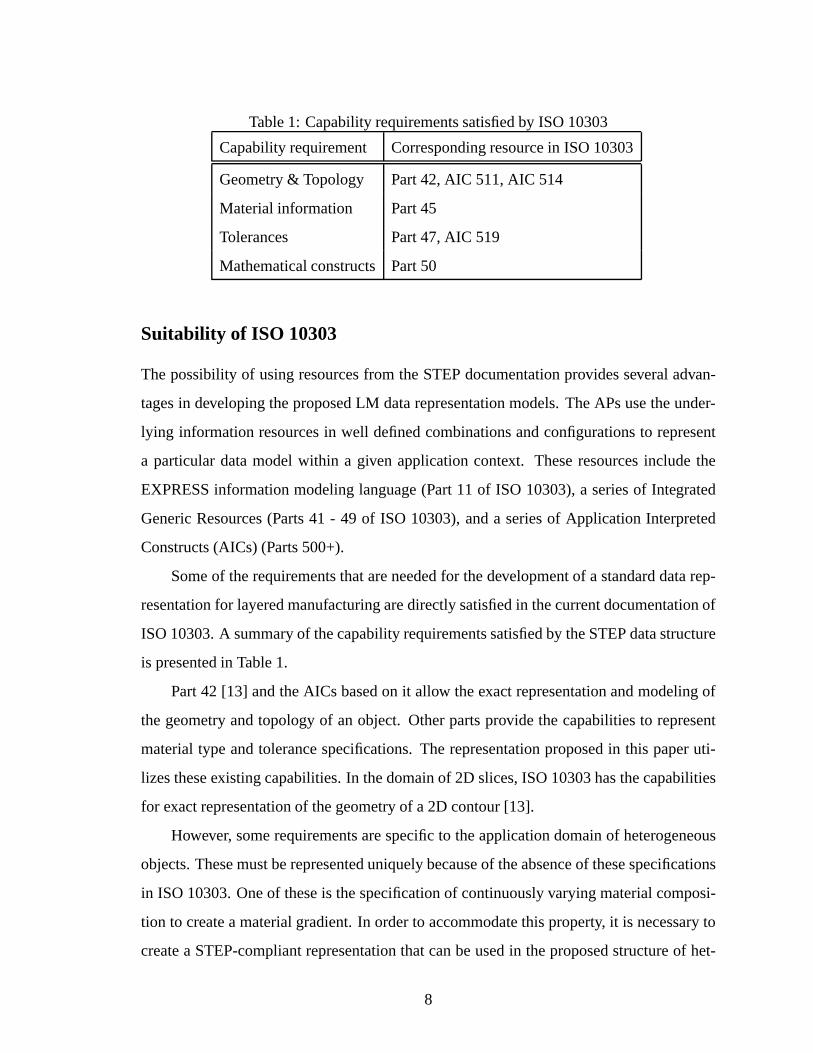
Table1: Capabilityrequirementssatisfiedby ISO10303
Capabilityrequirement Correspondingresourcein ISO10303
Geometry& Topology Part42,AIC 511,AIC 514
Materialinformation Part45
Tolerances Part47,AIC 519
Mathematicalconstructs Part50
Suitability of ISO 10303
Thepossibilityof usingresourcesfrom theSTEPdocumentationprovidesseveraladvan-
tagesin developingtheproposedLM datarepresentationmodels.TheAPsusetheunder-
lying informationresourcesin well definedcombinationsandconfigurationsto represent
a particulardatamodelwithin a given applicationcontext. Theseresourcesincludethe
EXPRESSinformationmodelinglanguage(Part 11 of ISO 10303),a seriesof Integrated
GenericResources(Parts41 - 49 of ISO 10303),anda seriesof Application Interpreted
Constructs(AICs) (Parts500+).
Someof therequirementsthatareneededfor thedevelopmentof a standarddatarep-
resentationfor layeredmanufacturingaredirectlysatisfiedin thecurrentdocumentationof
ISO10303.A summaryof thecapabilityrequirementssatisfiedby theSTEPdatastructure
is presentedin Table1.
Part 42 [13] andtheAICs basedon it allow theexactrepresentationandmodelingof
the geometryandtopologyof anobject. Otherpartsprovide the capabilitiesto represent
materialtype andtolerancespecifications.The representationproposedin this paperuti-
lizestheseexistingcapabilities.In thedomainof 2D slices,ISO10303hasthecapabilities
for exactrepresentationof thegeometryof a2D contour[13].
However, somerequirementsarespecificto theapplicationdomainof heterogeneous
objects.Thesemustberepresenteduniquelybecauseof theabsenceof thesespecifications
in ISO10303.Oneof theseis thespecificationof continuouslyvaryingmaterialcomposi-
tion to createa materialgradient.In orderto accommodatethis property, it is necessaryto
createa STEP-compliantrepresentationthatcanbeusedin theproposedstructureof het-
8
erogeneoussolid modeling[14]. This leadsto theintroductionof new entitiesconforming
to the STEPdatastructure.A specializationof this informationmodelto the2D domain
will servefor therepresentationof gradedmaterialdistributionsin theinteriorof 2D slices.
After astudyof ISO10303andheterogeneoussolidmodeling,a dataplanningmodel
(DPM) is proposedasafirst steptowardstherepresentationof heterogeneoussolidsin the
domainof ISO10303.Theremainderof thepaperdiscussesthisDPM.
4 Data Planning Model (DPM)
A dataplanningmodelillustratestheprimaryconceptsof theapplicationdomainandthe
generalrelationshipsamongthemajorconcepts.It doesnot fully describethedetailsof the
relationships.It providesanoverview of thescopeof theapplicationdomain.
Thestructureof ISO10303wasreviewedandspecificdocuments(parts)in ISO10303
werestudiedin detail.Thesepartswereanalyzedto determineif they satisfiedtherequire-
ments.It wasfoundthatsomeentitiesrequiredfor representingheterogeneoussolidmodels
arenot availablein ISO 10303. Therefore,appropriateentitieswerecreatedusingorigi-
nal datarepresentationswritten in theSTEPcomputer-interpretableinformationmodeling
languageEXPRESS[15].
Dataplanningmodelsareproposedat two levelsof thedatatransferfor layeredmanu-
facturing.TheDPM presentedin Section4.1is aproposedstructureto representheteroge-
neoussolidobjectsin thedomainof datatransferas3D CAD models.Section4.2presents
a proposedstructureto representinformationin a 2D slicedomainof layeredmanufactur-
ing. Both thesemodelsaccountfor thematerialgradationandareaimedto bethebasisof
neutralfile formatsfor datatransferamongvariouscommercialLM machines.
Theproposeddataplanningmodelsdepictonly a high level presentationof thepro-
posedformatsusing the EXPRESS-Gmodelinglanguage.The EXPRESS-Gmodeling
languageis a formal graphicalnotationfor the displayof dataspecificationsdefinedin
theEXPRESSlanguage[15]. TheDPMsdo not provide detailedinternalworking of the
structure.However, they provide anoverall structureandthenecessarycapabilitiesof the
representationbeforedevelopinga moredetailedlow level representationof the specific
9
material_solid_model_representation
material_solid_representation_item
INTEGER
product_property_definition_schema.shape_aspect
aic_advanced_brep.geometric_representation_item
aic_advanced_brep.topological_representation_item
material_property
material_representation_item geometry_schema.
axis2_placement_3d
geometry_schema.point
ISO13854_generic_expressions_schema.generic_expression
mathematical_functions_schema.maths_function
geometry_schema.curve
geometry_schema.surface
function_applicationmathematical_functions_schema.
items S[1:?]no_of_materials
local_co-ord_axes
items S[1:no_of_materials]
functionarguments L[1:?]
reference_item
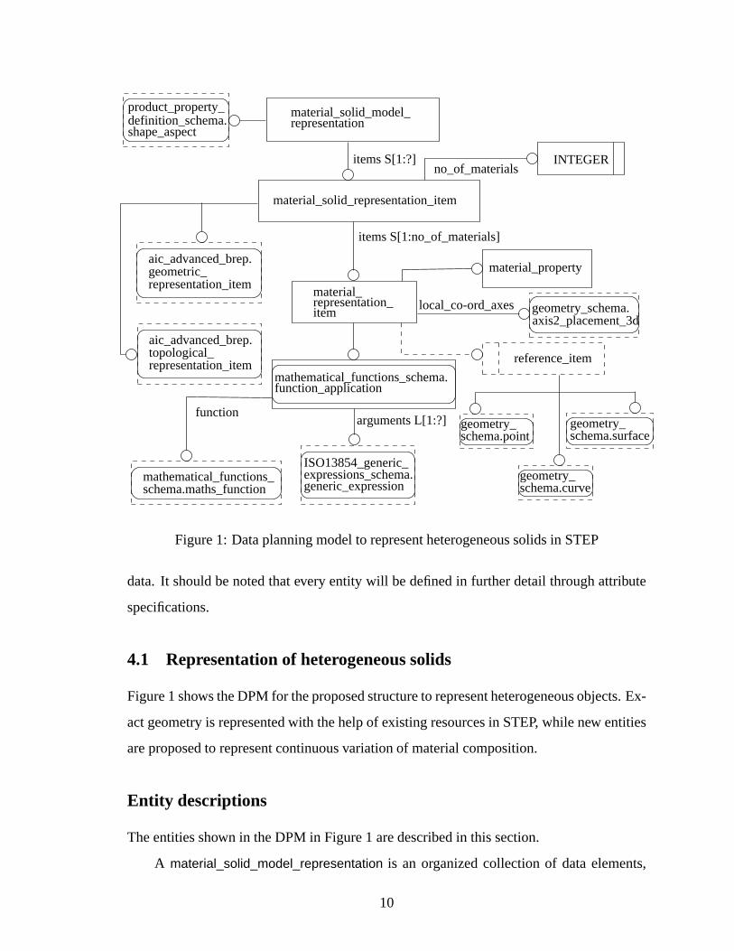
Figure1: Dataplanningmodelto representheterogeneoussolidsin STEP
data.It shouldbenotedthatevery entity will bedefinedin furtherdetail throughattribute
specifications.
4.1 Representation of heterogeneous solids
Figure1 showstheDPM for theproposedstructureto representheterogeneousobjects.Ex-
actgeometryis representedwith thehelpof existing resourcesin STEP, while new entities
areproposedto representcontinuousvariationof materialcomposition.
Entity descriptions
Theentitiesshown in theDPM in Figure1 aredescribedin thissection.
A material_solid_model_representation is an organizedcollectionof dataelements,
10
collectedtogetherto representany solid modelwith materialpropertiesassociatedwith it.
It thusrepresentsanrm-object.
The entity material_solid_representation_item forms an attribute of the entity mate-
rial_solid_model_representation. Thus,material_solid_model_representation comprisesin-
stancesof material_solid_representation_item to representan individual materialset(rm-
set)of the objectmodel. Theexistenceof morethanonerm-set in the materialobjectis
representedby multiple instancesof a material_solid_representation_item within thesame
materials_solid_model_representation.
The geometryand the topology of the 3D solid are representedby attributesgeo-
metric_representation_item and topological_representation_item respectively. Theseare
definedin Part 514 [16] of the ISO 10303documentation.The materialpropertiesand
the compositionis representedby an entity called material_representation_item. This
correspondsto the definition that an rm-object is definedasa finite collectionof rm-sets
{( Pi B j )}.
Entity material_solid_representation_item hasan attribute with an integer datatype
(no_of_materials) to representthe numberof the materialsusedin the representationfor
a rm-set. Every material_solid_representation_item comprisesa set of no_of_materials
numberof instancesof thematerial_representation_item. This consistsof theentity mate-
rial_property asoneof its attributes.This entity constitutestheindividualpropertiesof the
materialin concern.Part45 [17] of ISO10303servesasthebasisfor thisentity.
Therecanbemultiplemethodsto representthematerialgradientfunction.Therefore,
a local co-ordinatesystemis definedto aid in thedefinitionof thematerialfunction.Local
co-ordinateaxesarerepresentedby axis2_placement_3d. Geometryinformationmayalso
beassociatedwith thedefinitionof thematerialdistributionfunction.Thereforeanoptional
selecttypeentity, reference_item is introduced.This selectsoneof theentitiesviz. point,
curve, surface asthereferenceentityfor variablesin thefunction.Theseentitiesarealready
definedin Part42 [13] of theISO10303documentation.
Thecompositemathematicalfunctionthatrepresentsthematerialcompositionfor an
instanceof the rm-set is representedby the attribute function_application (usedfrom the
mathematical_constructs_schema [18]). It utilizesa maths_function anda corresponding
11
list of arguments. This (function_application) representstheoperationof applyinga math-
ematicalfunctionto anappropriatesetof arguments.Theentitymaths_function represents
thefunctionto beapplied.Theargumentsin thiscasewouldbethetuple(x y z) thatrepre-
sentstheCartesianco-ordinatesof thegeometricpoint in thatr-set.Thefunctionthus,may
berepresentedasF�x y z� . A moredetailedexplanationof thisentity(function_application)
canbefoundin [18].
Therepresentationissuchthatany assembly/parttobephysicallyrealizedcanbein the
domainof heterogeneousobjects.A componentwith a homogeneousmaterialdistribution
will becharacterizedby exactlyonematerial(no_of_materials = 1) andthecorresponding
materialdistributionfunctionwill beF � 1.
A shape_aspect is associatedwith every material_solid_model_representation. This
attributedis referencedfrom product_property_definition_schema. Entitiessuchasdatum,
datum_feature andtolerance_zone aredefinedin this scheme.Theseentitiesrepresentthe
tolerancesassociatedwith anobject. Detailedexplanationsof theseentitiescanbefound
in Part47 [19] andAIC 519[20].
4.2 Representation of heterogeneous slices
Theability of LM machinesto fabricateheterogeneousobjectssuggestsa needfor incor-
poratingvaryingmaterialcompositioninto thesliceinformation.Section4.1discussedthe
representationof heterogeneoussolidsusingconceptsfrom ISO10303.A similarapproach
canbeutilized to representa gradientin thematerialcompositionin the2D slicedomain.
Figure2 shows the dataplanningmodel for the proposedstructureto representslice in-
formationfor heterogeneousobjects.This modelis alsopresentedusingtheEXPRESS-G
notation.Theability of ISO10303to representexactgeometriesis utilizedto representthe
contoursin aslice.Thus,poly-lineapproximationdoesnot form thebasisof this represen-
tation.
Entity descriptions
Theentitiesgivenin theDPM of Figure2 aredescribedin thissection.
12
aic_advanced_brep.advanced_face* representation_
item
material_geometry_schema.axis2_placement_2d
material_property
material_region_representation_item
geometry_schema.point
geometry_schema.curve
REAL REALslice_representation_item
material_solid_model_representation geometry_schema.direction
orientation
INTEGER
function_applicationmathematical_functions_schema.
mathematical_functions_schema.maths_function
ISO13854_generic_expressions_schema.generic_expression
local_co-ord_axes
items S[1:no_of_materials]
arguments L[1:?]
reference_item
function
height thickness
items S[1:?]
no_of_materialsitems S[1:?]
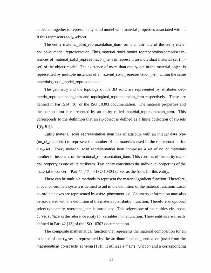
Figure2: Dataplanningmodelto representsliceinformation
A material_solid_model_representation representsa heterogeneoussolid. It is pro-
cessedthroughtheorientationmoduleandanappropriateorientation is determined.This
orientationis representedby theentity direction. Theentity direction is definedin geome-
try_schema of Part 42 [13] of the ISO 10303documentation.Thusorientation represents
thedirectionof stackingtheslices.Theslicesaregeneratednormalto thisdirection.
As a resultof slicing,a material_solid_model_representation comprisesa finite setof
slice_representation_item. Eachslice_representation_item representsan individual slice.
Slice thickness andheight of the slice from the baseareattributesassociatedwith every
slice.They arerepresentedasrealnumbers.
13
Every slice is anorganizedcollectionof dataelementsrepresentedby theentity ma-
terial_region_representation_item, whichrepresentsa2D regionon theslice.Theunionof
suchregionswhichhavedisjointgeometricinteriorsrepresentsasingleslice.
The geometryof the region canbe representedasan advanced_face definedin Part
511 [21]. It is a specialtypeof face_surface thathasadditionalconstraintsto ensurethat
the geometryis directly andcompletelydefined. It is requiredto be fully boundedby at
leastone face_bound which is a topologicalentity representinga loop. In this case,the
slice is a planarentity. Therefore,the facegeometryshall be restrictedto a plane. More
informationon theseentitiescanbeobtainedin [13, 21].
The material_region_representation_item hasan attribute with an integer datatype
(no_of_materials) to representthe numberof the materialsusedin the representationof
theregion. Everymaterial_region_representation_item consistsof asetof no_of_materials
numberof instancesof thematerial_representation_item. This consistsof theentity mate-
rial_property asoneof its attributes.This entity constitutestheindividualpropertiesof the
materialin concern.Part45[17]of ISO-10303servesasthebasisfor thisentity.
Therecanbe multiple methodsto representthe function for representinga material
gradient. In order to addressthis ambiguity, a local co-ordinatesystemis definedto
aid in the definition of the materialfunction. Local co-ordinateaxesarerepresentedby
axis2_placement_2d, which is an entity alreadydefinedin Part 42 [13] of ISO 10303.
Geometryinformationmayalsobeassociatedwith thedefinition. Therefore,anoptional
selecttypeentity reference_item thatselectsa point or a curve asthegeometricreference
entity for thevariablesin the function. Both of theseentitiesarereferencedfrom thege-
ometry_schema of Part42 [13] of ISO10303.
The compositemathematicalfunction to representthe gradientin materialcomposi-
tion in the region is representedby the attribute function_application (usedfrom mathe-
matical_constructs_schema [18]). This utilizesa maths_function anda correspondinglist
of arguments. It (function_application) representstheoperationof applyinga mathemati-
cal function to anappropriatesetof arguments.Theentity maths_function representsthe
functionto beapplied.Theargumentsin this casewould bethetuple(x y) thatrepresents
theCartesianco-ordinatesof a geometricpoint in that region. The function thus,maybe
14
representedasF�x y� . A moredetailedexplanationof theentity function_application can
befoundin [18].
This informationmodelis basedontheset-basedmethodof heterogeneoussolidmod-
eling [1]. Thetheoryis appliedto a2D domain.A slicecanbeconsideredto beequivalent
to anrm-object.It consistsof geometrically, interior-disjoint regions.Eachregion is equiv-
alentto an rm-set. Theadvanced_face representsthegeometryof the region. A material
distribution functionis usedto representthematerialgradientin this region.
5 Validation
The dataplanningmodelsproposedin Section4 needto be validatedto checkfor the
correctnessof therepresentation.
In the domainof ISO 10303validationmeanstestingwhetherthe syntaxof an EX-
PRESSschemais correctandwhetherall appropriateexternalreferences(to entitiesde-
finedin otherschema)aremade.It shouldbenotedthatthis is nottheconceptof validation
consideredin this section. However, this validationprocessis a requiredcomponentfor
developmentof anew STEPAP.
A two-level validationscheme,basedon the available resources,wasdevelopedto
physicallyfabricatepartsrepresentedin theproposedSTEPformat.
5.1 Validation of the solid model representation
Several samplecasestudieswereconsideredfor validation. Datafiles conformingto the
proposedformatandSTEPrulesfor mappingEXPRESSto physicalfile formatwerefirst
generatedmanually. Theseweremanuallycheckedto seeif theproposedformatcontained
all the requiredinformationaboutthegeometryintegratedwith the materialinformation.
However, for physicalfabricationof parts,the solid modelhasto be sliced. Themanual
checkis thuscomplementedby the developmentof a slice level representationwhich is
usedto fabricatephysicalpartsat theUniversityof Michigan,Ann Arbor.
15
Sanders slice format
... slice format
FDM slice format
Slice file in STEP format
BSplineLine Circle
1
1
1
1
1
1
1
1
1
writeFDM()
writeSanders()
write...()
readStepFile()MatRegion
AdvancedFace
FaceBound
Edge
MatRepresentationItem
StepObject
Curve
SliceRepresentationItemMatSolidRepresentation
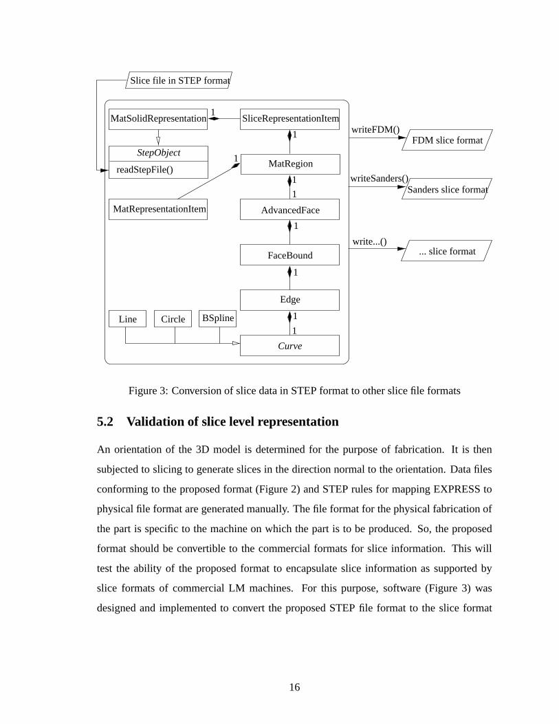
Figure3: Conversionof slicedatain STEPformatto otherslicefile formats
5.2 Validation of slice level representation
An orientationof the 3D model is determinedfor the purposeof fabrication. It is then
subjectedto slicing to generateslicesin thedirectionnormalto theorientation.Datafiles
conformingto theproposedformat (Figure2) andSTEPrulesfor mappingEXPRESSto
physicalfile formataregeneratedmanually. Thefile formatfor thephysicalfabricationof
the part is specificto the machineon which the part is to beproduced.So, theproposed
format shouldbe convertible to the commercialformatsfor slice information. This will
test the ability of the proposedformat to encapsulateslice informationas supportedby
slice formatsof commercialLM machines. For this purpose,software (Figure 3) was
designedand implementedto convert the proposedSTEPfile format to the slice format
16
of commercialLM machines.1 A successfulconversionis validatedby visualizing the
generatedslicefilesusingtheproprietarysoftwareof theLM machines.Fabricationof the
final physicalpart on the commercialLM machinesprovidesa physicalvalidationto the
encapsulationof informationof theslicegeometry.
The conversionsoftware(Figure3) readsin all informationrepresentedin the pro-
posedneutralslicefile andstoresit in aclassstructurecompatiblewith theproposedstruc-
ture in ISO 10303(Figure2). The hierarchicalnatureof the datastructurein STEPfa-
cilitatesits implementationin theobjectorientedparadigmusingC++ asa programming
tool.
Theclassdiagramin Figure3 is shown in accordancewith theOMG Unified Model-
ing LanguageSpecification[22]. ClassStepObjectis theparentabstractclass.Thevirtual
methodreadStepFile is usedto readthephysicalSTEPfile (containingsliceinformation).
MatSolidRepresentationrepresentsa slicedheterogeneoussolid. Thus,SliceRepresenta-
tionItem (2D rm-object) forms the elementsfor the compositionof a MatSolidRepresen-
tation. Every slice is composedof a finite numberof MatRegions(2D rm-set). OneAd-
vancedFaceanda finite numberof MatRepresentationItemsform oneMatRegion. Each
MatRepresentationItemis definedby amathematicalfunctionto representthematerialdis-
tribution. Every AdvancedFaceis definedby a finite numberof boundaries(FaceBound).
A closedFaceBoundis madeof oneor moreEdges. An Edge is composedof a Curve.
ClassCurveis anabstractclassthatcanberepresentedasaLine, aCircleor aBSpline.
This informationstoredin the memoryof the computerhasto be convertedinto a
machinespecificphysicalfile format. This purposeis solvedby writing routinessuchas
WriteFDM to convert theinformationinto theFDM sliceformat. Thesamedatastructure
canbe utilized to outputinformationthrougha moduleto print the informationin a par-
ticular slicefile format. Thesoftwareis thusa post-processorthatprocessesSTEPbased
sliceinformationto themachinespecificsliceinformation.
Thesliceinformationfor thefabricationof a parton oneparticularLM machinemay
bevalid for thefabricationof thepartusingadifferentLM technology. A singleSTEPfile
1TheStratasys’FDM 3D modelerandSandersPrototype’s Modelmaker areusedasrepresentative ma-
chines
17
(a)HSM(Rectangulargeometry)
P1
P2
F11 F
12
B2
P3
F13
B3B1
0 0.5 0.6 1
Y
X
S � � P1 � B1 � � � P2 � B2 � � � P3 � B3 � �P1 � � x � y� � 0 � x � 50� 0 � y � 20�P2 � � x � y� � 50 � x � 60� 0 � y � 20�P3 � � x � y� � 60 � x � 100� 0 � y � 20�B1 � � 0 � 01 � x� 2 � 1 � � 0 � 01 � x� 2 �B2 � 0 � 25� 0 � 75�B3 � 1 � 5 � 0 � 01 � x � 0 � 5 � 0 � 5 � 1 � 5 � 0 � 01 � x�
1
(b) rm objectmodel
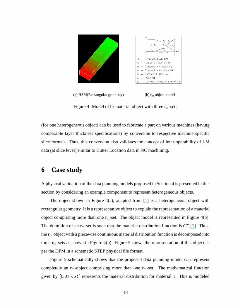
Figure4: Modelof bi-materialobjectwith threerm-sets
(for oneheterogeneousobject)canbeusedto fabricateapartonvariousmachines(having
comparablelayer thicknessspecifications)by conversionto respective machinespecific
slice formats. Thus,this conversionalsovalidatestheconceptof inter-operabilityof LM
data(at slicelevel) similar to CutterLocationdatain NC machining.
6 Case study
A physicalvalidationof thedataplanningmodelsproposedin Section4 is presentedin this
sectionby consideringanexamplecomponentto representheterogeneousobjects.
The object shown in Figure 4(a), adaptedfrom [1] is a heterogeneousobject with
rectangulargeometry. It is arepresentativeobjectto explaintherepresentationof amaterial
objectcomprisingmorethanonerm-set. Theobjectmodelis representedin Figure4(b).
Thedefinitionof anrm-setis suchthat thematerialdistribution function is C∞ [1]. Thus,
therm objectwith apiecewisecontinuousmaterialdistributionfunctionis decomposedinto
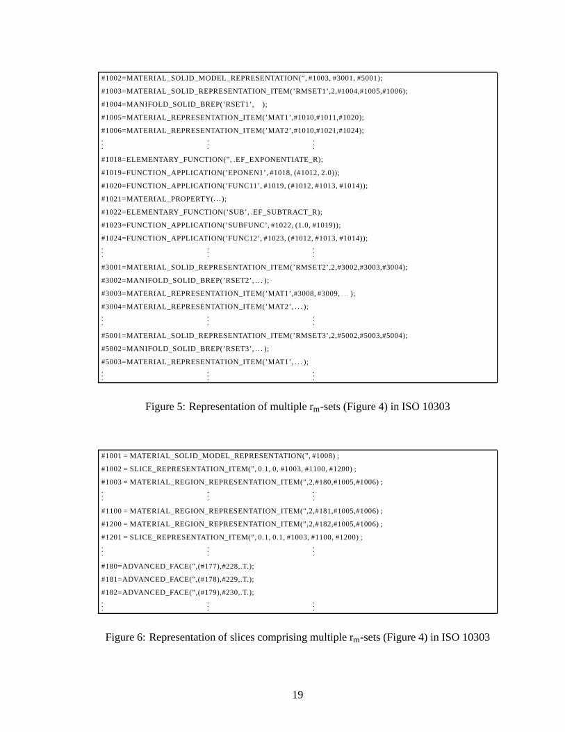
threerm-setsasshown in Figure4(b). Figure5 shows the representationof this objectas
pertheDPM in a schematicSTEPphysicalfile format.
Figure5 schematicallyshows that the proposeddataplanningmodelcan represent
completelyan rm-object comprisingmore than one rm-set. The mathematicalfunction
given by�0 � 01 � x� 2 representsthe materialdistribution for material1. This is modeled
18
#1002=MATERIAL_SOLID_MODEL_REPRESENTATION(” , #1003, #3001, #5001);
#1003=MATERIAL_SOLID_REPRESENTATION_ITEM(’ RMSET1’ ,2,#1004,#1005,#1006);
#1004=MANIFOLD_SOLID_BREP(’ RSET1’ , ����� );#1005=MATERIAL_REPRESENTATION_ITEM(’ MAT1’ ,#1010,#1011,#1020);
#1006=MATERIAL_REPRESENTATION_ITEM(’ MAT2’ ,#1010,#1021,#1024);...
......
#1018=ELEMENTARY_FUNCTION(” , .EF_EXPONENTIATE_R);
#1019=FUNCTION_APPLICATION(’ EPONEN1’ , #1018, (#1012, 2.0));
#1020=FUNCTION_APPLICATION(’ FUNC11’ , #1019, (#1012, #1013, #1014));
#1021=MATERIAL_PROPERTY( ����� );#1022=ELEMENTARY_FUNCTION(’ SUB’ , .EF_SUBTRACT_R);
#1023=FUNCTION_APPLICATION(’ SUBFUNC’ , #1022, (1.0, #1019));
#1024=FUNCTION_APPLICATION(’ FUNC12’ , #1023, (#1012, #1013, #1014));...
......
#3001=MATERIAL_SOLID_REPRESENTATION_ITEM(’ RMSET2’ ,2,#3002,#3003,#3004);
#3002=MANIFOLD_SOLID_BREP(’ RSET2’ , ����� );#3003=MATERIAL_REPRESENTATION_ITEM(’ MAT1’ ,#3008, #3009, ����� );#3004=MATERIAL_REPRESENTATION_ITEM(’ MAT2’ , ����� );...
......
#5001=MATERIAL_SOLID_REPRESENTATION_ITEM(’ RMSET3’ ,2,#5002,#5003,#5004);
#5002=MANIFOLD_SOLID_BREP(’ RSET3’ , ����� );#5003=MATERIAL_REPRESENTATION_ITEM(’ MAT1’ , ����� );...
......
Figure5: Representationof multiple rm-sets(Figure4) in ISO10303
#1001 = MATERIAL_SOLID_MODEL_REPRESENTATION(” , #1008) ;
#1002 = SLICE_REPRESENTATION_ITEM(” , 0.1, 0, #1003, #1100, #1200) ;
#1003 = MATERIAL_REGION_REPRESENTATION_ITEM(” ,2,#180,#1005,#1006) ;...
......
#1100 = MATERIAL_REGION_REPRESENTATION_ITEM(” ,2,#181,#1005,#1006) ;
#1200 = MATERIAL_REGION_REPRESENTATION_ITEM(” ,2,#182,#1005,#1006) ;
#1201 = SLICE_REPRESENTATION_ITEM(” , 0.1, 0.1, #1003, #1100, #1200) ;...
......
#180=ADVANCED_FACE(” ,(#177),#228,.T.);
#181=ADVANCED_FACE(” ,(#178),#229,.T.);
#182=ADVANCED_FACE(” ,(#179),#230,.T.);...
......
Figure6: Representationof slicescomprisingmultiple rm-sets(Figure4) in ISO10303
19
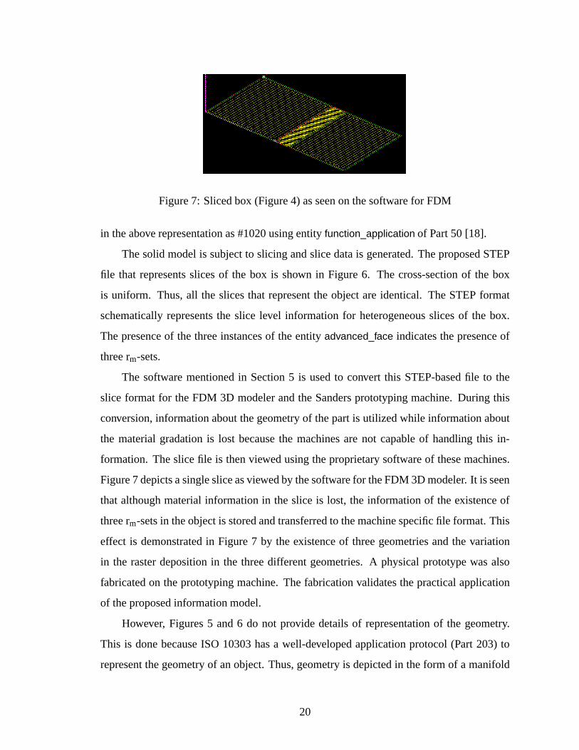
Figure7: Slicedbox (Figure4) asseenon thesoftwarefor FDM
in theaboverepresentationas#1020usingentity function_application of Part50 [18].
Thesolid modelis subjectto slicing andslicedatais generated.TheproposedSTEP
file that representsslicesof the box is shown in Figure6. The cross-sectionof the box
is uniform. Thus,all the slicesthat representthe objectareidentical. The STEPformat
schematicallyrepresentsthe slice level informationfor heterogeneousslicesof the box.
Thepresenceof the threeinstancesof theentity advanced_face indicatesthepresenceof
threerm-sets.
The softwarementionedin Section5 is usedto convert this STEP-basedfile to the
slice format for theFDM 3D modelerandthe Sandersprototypingmachine.During this
conversion,informationaboutthegeometryof thepartis utilizedwhile informationabout
the materialgradationis lost becausethe machinesare not capableof handlingthis in-
formation. Theslicefile is thenviewedusingtheproprietarysoftwareof thesemachines.
Figure7 depictsasinglesliceasviewedby thesoftwarefor theFDM 3D modeler. It is seen
that althoughmaterialinformationin the slice is lost, the informationof the existenceof
threerm-setsin theobjectis storedandtransferredto themachinespecificfile format.This
effect is demonstratedin Figure7 by the existenceof threegeometriesandthe variation
in the rasterdepositionin the threedifferentgeometries.A physicalprototypewasalso
fabricatedon theprototypingmachine.Thefabricationvalidatesthepracticalapplication
of theproposedinformationmodel.
However, Figures5 and6 do not provide detailsof representationof the geometry.
This is donebecauseISO 10303hasa well-developedapplicationprotocol(Part 203) to
representthegeometryof anobject.Thus,geometryis depictedin theform of a manifold
20
b-rep solid representationfor the solid and advancedfacefor the slice. The detailsof
the representationof this solid geometryis shown in AppendixA. It presentsa typical
representationandothergeometriescanberepresentedin asimilarmanner.
7 Conclusion
The DPM (Data PlanningModel) proposedin Section4.1 providesan overview of the
methodologyandthestructureto representheterogeneoussolidsusingtheconceptsof ISO
10303.TheDPM representsacompleteintegrationof materialinformationwith thecorre-
spondinggeometryto representheterogeneousobjectsasproposedin [1].
TheDPMproposedin Section4.2providesaslicelevel representationscheme.It helps
in validationof theDPM for representingheterogeneoussolidsby physicalrealizationof
the objects. It canalsobe usedto demonstratean initial conceptof utilizing slice level
informationasaneutralfile formatfor thetransferof dataamongdifferentLM machines.
Useof ISO 10303(STEP)asthebasiswill allow for fasterstandardizationandadop-
tion becausethecoreSTEPfunctionalityhasreachedconsensusandhasbeenalsoimple-
mentedin softwaresystems.
To enablecompleteSTEP-baseddatatransferin LayeredManufacturing,additional
aspectsof heterogeneoussolid modelingand the down-line transferof datafor process
planningneedto beconsidered.Someof theseareasfollows:
1. Representationof objectpropertiessuchascolorandsurfacefinish.
2. Developmentof an informationmodelto representdatarequirementsfor theentire
processplanningfor layeredmanufacturing
The format of representationof heterogeneousobjectsin a standardizedformat will
bean importantsteptowardsthesuccessfulphysicalrealizationof heterogeneousobjects
throughlayeredmanufacturing.
21
ACKNOWLEDGMENT
Patil and Dutta acknowledgethe financial support(Grant #70NANB9H0053) from Na-
tional Instituteof StandardsandTechnology, Gaithersburg, Maryland. We would like to
thank NIST’s SystemIntegration for ManufacturingApplications(SIMA) programand
DARPA’s Rapid DesignExplorationand Optimization(RaDEO)programfor providing
partialsupportfor thiswork.
Disclaimer
No approval or endorsementof any commercialproductby theNationalInstituteof Stan-
dardsandTechnologyis intendedor implied. Certaincommercialequipment,instruments,
or materialsareidentifiedin thispaperin orderto facilitateunderstanding.Suchidentifica-
tion doesnot imply recommendationor endorsementby theNationalInstituteof Standards
andTechnology, nordoesit imply thatthematerialsor equipmentidentifiedarenecessarily
thebestavailablefor thepurpose.
References
[1] Vinod KumarandDebasishDutta. An Approachto ModelingandRepresentationof
HeterogeneousObjects.ASMEjournal of mechanicaldesign, 120:659–667,Decem-
ber1998.
[2] DebasishDutta,Vinod Kumar, MikeJ.Pratt,andR.D.Sriram.TowardsSTEP-based
DataTransferin LayeredManufacturing. In Proceedingsof the tenthinternational
IFIP WG5.2/5.3PROLAMAT Conference, Trento,Italy, September1998.
[3] Lalit Patil, DebasishDutta,A. D. Bhatt,K. Jurrens,K. Lyons,M. J.Pratt,andR. D.
Sriram. Representationof heterogeneousobjectsin ISO 10303(STEP). In Pro-
ceedingsof theASMEManufacturingEngineeringDivision 2000, volume11, pages
355–364,Orlando,FL, 2000.
22
[4] T. R. Jackson,N. M. Patrikalakis,E.M. Sachs,andM.J.Cima.Modelinganddesign-
ing componentswith Locally ControlledComposition. In Proceedingsof the Solid
FreeformFabricationSymposium, Austin,TX, 1998.
[5] Wu Zhongke,SeahHockSoon,andLin Feng.NURBS-BasedVolumeModeling. In
InternationalWorkshoponVolumeGraphics, pages321–330,Swansea,UK, 1999.
[6] V. L. Rvachev, T. I Sheiko, V. Shapiro,andI. Tsukanov. TransfiniteInterpolation
over Implicitly DefinedSets. TechnicalReportSAL 2000– 1, SpatialAutomation
Laboratory, Universityof Wisconsin- Madison,2000.
[7] Seok-MinPark,RichardCrawford, andJosephBeaman.FunctionallyGradedMate-
rial Representationby VolumetricMulti-Texturingfor SolidFreeformFabrication.In
Proceedingsof the11thAnnualSolidFreeformFabricationSymposium, Austin,TX,
August2000.
[8] A.V KumarandA. Wood. Representationanddesignof heterogeneouscomponents.
In Proceedingsof the1999SolidFreeformFabricationSymposium, pages179–186,
Austin,TX, August1999.
[9] A. A. G. Requicha. Representationof rigid solids - theory, methodsandsystems.
ACM ComputingSurveys, 12:437–464,1980.
[10] AnneMarsan,Vinod Kumar, DebasishDutta,andMike J. Pratt. An Assessmentof
DataRequirementsand DataTransferFormatsfor LayeredManufacturing. Tech-
nical ReportNISTIR 6216,NationalInstituteof StandardsandTechnology(NIST),
Gaithersburg, Maryland,September1998.
[11] Kevin Jurrens.Standardsfor therapidprototypingindustry. RapidPrototypingJour-
nal, 5(4):169–178,1999.
[12] TheSTEPProject. URL: http://www.nist.gov/sc4/www/stepdocs.htm,valid asof Jan-
uary2001.
23
[13] Industrial automationsystemsandintegration - Productdatarepresentationandex-
change- Part 42: Integratedgenericresources:Geometricandtopological represen-
tation, ISO10303-42:2000.
[14] VinodKumar. SolidModelingandAlgorithmsfor HeterogeneousObjects. PhDthesis,
Universityof Michigan,Ann Arbor, 1999.
[15] Industrial automationsystemsandintegration - Productdatarepresentationandex-
change - Part 11: Descriptionmethods:TheEXPRESSlanguage referencemanual,
ISO/WD10303-11:1998ed-2.
[16] Industrial automationsystemsandintegration - Productdatarepresentationandex-
change - Part 514: Applicationinterpretedconstruct:Advancedboundaryrepresen-
tation, ISO10303-514:1999.
[17] Industrial automationsystemsandintegration - Productdatarepresentationandex-
change- Part 45: Integratedgenericresources:Materials, ISO10303-45:1998.
[18] Industrial automationsystemsandintegration - Productdatarepresentationandex-
change - Part 50: Integratedgenericresources: Mathematicalconstructs, ISO/CD
10303-50:1999.
[19] Industrial automationsystemsandintegration - Productdatarepresentationandex-
change - Part 47: Integrated generic resources: Shapevariation tolerances, ISO
10303-47:1998.
[20] Industrial automationsystemsandintegration - Productdatarepresentationandex-
change - Part 519: Application interpretedconstruct: Geometrictolerances, ISO
10303-519:2000.
[21] Industrial automationsystemsandintegration - Productdatarepresentationandex-
change- Part 511: Applicationinterpretedconstruct:Topologicallyboundedsurface,
ISO/FDIS10303-511:1997.
24

[22] OMG Unified Modeling Language specification,version 1.3. available at URL:
http://www.rational.com/uml/resources/documentation/index.jsp,June1999.
25
Appendix A
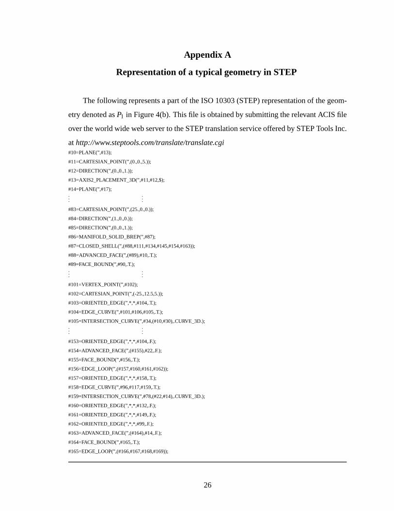
Representation of a typical geometry in STEP
Thefollowing representsapartof theISO10303(STEP)representationof thegeom-
etrydenotedasP1 in Figure4(b). Thisfile is obtainedby submittingtherelevantACISfile
over theworld widewebserver to theSTEPtranslationserviceofferedby STEPToolsInc.
athttp://www.steptools.com/translate/translate.cgi#10=PLANE(”,#13);
#11=CARTESIAN_POINT(”,(0.,0.,5.));
#12=DIRECTION(”,(0.,0.,1.));
#13=AXIS2_PLACEMENT_3D(”,#11,#12,$);
#14=PLANE(”,#17);...
...
#83=CARTESIAN_POINT(”,(25.,0.,0.));
#84=DIRECTION(”,(1.,0.,0.));
#85=DIRECTION(”,(0.,0.,1.));
#86=MANIFOLD_SOLID_BREP(”,#87);
#87=CLOSED_SHELL(”,(#88,#111,#134,#145,#154,#163));
#88=ADVANCED_FACE(”,(#89),#10,.T.);
#89=FACE_BOUND(”,#90,.T.);...
...
#101=VERTEX_POINT(”,#102);
#102=CARTESIAN_POINT(”,(-25.,12.5,5.));
#103=ORIENTED_EDGE(”,*,*,#104,.T.);
#104=EDGE_CURVE(”,#101,#106,#105,.T.);
#105=INTERSECTION_CURVE(”,#34,(#10,#30),.CURVE_3D.);...
...
#153=ORIENTED_EDGE(”,*,*,#104,.F.);
#154=ADVANCED_FACE(”,(#155),#22,.F.);
#155=FACE_BOUND(”,#156,.T.);
#156=EDGE_LOOP(”,(#157,#160,#161,#162));
#157=ORIENTED_EDGE(”,*,*,#158,.T.);
#158=EDGE_CURVE(”,#96,#117,#159,.T.);
#159=INTERSECTION_CURVE(”,#78,(#22,#14),.CURVE_3D.);
#160=ORIENTED_EDGE(”,*,*,#132,.F.);
#161=ORIENTED_EDGE(”,*,*,#149,.F.);
#162=ORIENTED_EDGE(”,*,*,#99,.F.);
#163=ADVANCED_FACE(”,(#164),#14,.F.);
#164=FACE_BOUND(”,#165,.T.);
#165=EDGE_LOOP(”,(#166,#167,#168,#169));
26