A Project Report On PREDICTIVE MAINTENANCE AND OVERHAULING OF ROTARY EQUIPMENTS IN HPCL REFINERY
91
A Project Report On PREDICTIVE MAINTENANCE AND OVERHAULING OF ROTARY EQUIPMENTS IN HPCL REFINERY Submitted By NILESH GAONKAR NIKHIL PANBUDE HARSHAL DESAI Under the guidance of PROF ASHWANI SHARMA PROF M.F.ALVI Submitted as a partial fulfillment of Bachelor of Engineering B.E. (Semester VIII), MECHANICAL [2013 - 2014] from Rizvi College of Engineering New Rizvi Educational Complex, Off-Carter Road, Bandra(w), Mumbai - 400050 Affiliated to University of Mumbai
Transcript of A Project Report On PREDICTIVE MAINTENANCE AND OVERHAULING OF ROTARY EQUIPMENTS IN HPCL REFINERY

A
Project Report On
PREDICTIVE MAINTENANCE AND OVERHAULING OF ROTARY
EQUIPMENTS IN HPCL REFINERY
Submitted By
NILESH GAONKAR
NIKHIL PANBUDE
HARSHAL DESAI
Under the guidance of
PROF ASHWANI SHARMA
PROF M.F.ALVI
Submitted as a partial fulfillment of
Bachelor of Engineering
B.E. (Semester VIII), MECHANICAL
[2013 - 2014]from
Rizvi College of EngineeringNew Rizvi Educational Complex, Off-Carter Road,
Bandra(w), Mumbai - 400050
Affiliated to
University of Mumbai

CERTIFICATE
This is certify that the project report entitled
“PREDICTIVE MAINTAINANCE AND OVERHAULING OF ROTARY EQUIPMENTS IN
HPCL REFINERY”
Submitted By
NILESH GAONKAR
NIKHIL PANBUDE
HARSHAL DESAI
of Rizvi College of Engineering, MECHANICAL has been approved in partial fulfillment of require-
ment for the degree of Bachelor of Engineering.
Prof. Ashwani Sharma Prof. Deepak ChaudharyInternal Guide External Guide
Prof. Hussain Jasdanwala Dr. Varsha ShahHead of Department Principal
Prof. ———————– Prof. ————————Internal Examiner External Examiner
Date:

Acknowledgement
I am profoundly grateful to Prof. Ashwani Sharma and Prof. M.F. Alvi for their expert guidance
and continuous encouragement throughout to see that this project rights its target since its commence-
ment to its completion.
I would like to express deepest appreciation towards Dr. Varsha Shah, Principal RCOE, Mumbai and
Prof. Hussain Jasdanwala, HoD Mechanical Dept. whose invaluable guidance supported me in com-
pleting this project.
I express our heartfelt thanks to Mr V.K. Sinha, Sr. Manager (Training) -HPCL Mumbai Refinery, for
giving us his generous approval to perform In-plant project training.
I am particularly grateful to Mr Deepak Chaudhary (Rotary) -HPCL Mumbai Refinery, who guided
me with my project work in the company.
At last I must express my sincere heartfelt gratitude to all the staff members of Mechanical Department
who helped me directly or indirectly during this course of work.
NILESH GAONKAR
NIKHIL PANBUDE
HARSHAL DESAI

ABSTRACT
Rotary equipments are critical, non-substitutable links in production chains of process industries. And
thus by extension the largest consumers of power. The state of functioning of these determine the ulti-
mate production costs and capacity of these industries.
This project aims to provide us with insight in to the condition monitoring and predictive maintenance
of rotary equipments.
Through this project we would perform the key operations concerning rotating equipment design ba-
sis, maintenance, installation and condition monitoring to enable us to:
• Understand the effect of process and environmental changes on equipment operation, maintenance
and reliability
• Condition monitor equipment on a component basis to optimize up-time, mean time between fail-
ure (MTBF) and mean time to repair (MTTR)
• Select, audit and test the equipment that will produce highest safety and reliability in the field for
the lowest life cycle cost.

Contents
1 Introduction 1
2 Literature Survey 2
2.1 Maintenance . . . . . . . . . . . . . . . . . . . . . . . . . . . . . . . . . . . . . . . . . 2
2.2 Predictive or condition-based maintenance. . . . . . . . . . . . . . . . . . . . . . . . . 3
2.2.1 Need for predictive maintenance:- . . . . . . . . . . . . . . . . . . . . . . . . . 3
2.2.2 Benefits of Predictive maintenance:- . . . . . . . . . . . . . . . . . . . . . . . . 3
2.2.3 Predictive Maintenance Techniques:- . . . . . . . . . . . . . . . . . . . . . . . 4
2.3 Condition Monitoring . . . . . . . . . . . . . . . . . . . . . . . . . . . . . . . . . . . . 4
2.4 Vibration Monitoring and Analysis . . . . . . . . . . . . . . . . . . . . . . . . . . . . . 4
2.4.1 What is vibration? . . . . . . . . . . . . . . . . . . . . . . . . . . . . . . . . . 4
2.4.2 Wave fundamentals:- . . . . . . . . . . . . . . . . . . . . . . . . . . . . . . . . 5
2.5 Vibration terminology . . . . . . . . . . . . . . . . . . . . . . . . . . . . . . . . . . . 7
2.6 Vibration Monitoring for Predictive Maintenance . . . . . . . . . . . . . . . . . . . . . 7
2.7 Domains of vibration analysis:- . . . . . . . . . . . . . . . . . . . . . . . . . . . . . . . 8
2.7.1 Time domain:- . . . . . . . . . . . . . . . . . . . . . . . . . . . . . . . . . . . 8
2.7.2 Frequency domain (Spectrum):- . . . . . . . . . . . . . . . . . . . . . . . . . . 9
2.8 Vibration Measuring Equipment . . . . . . . . . . . . . . . . . . . . . . . . . . . . . . 11
2.9 Vibration Sources:- . . . . . . . . . . . . . . . . . . . . . . . . . . . . . . . . . . . . . 11
2.10 Vibration data collection by CSI 2130 machine health analyzer:- . . . . . . . . . . . . . 12
2.11 Failure detection by vibration monitoring : . . . . . . . . . . . . . . . . . . . . . . . . 15
2.12 Bearing failure parameters:- . . . . . . . . . . . . . . . . . . . . . . . . . . . . . . . . 21
2.13 Case Study . . . . . . . . . . . . . . . . . . . . . . . . . . . . . . . . . . . . . . . . . 24
2.13.1 Case Study of Pump 11P8B . . . . . . . . . . . . . . . . . . . . . . . . . . . . 24
2.13.2 Case Study of FD Fan SG9 . . . . . . . . . . . . . . . . . . . . . . . . . . . . 26
2.13.3 Case Study 12Fan1B . . . . . . . . . . . . . . . . . . . . . . . . . . . . . . . . 28
2.14 Rotating Unbalance . . . . . . . . . . . . . . . . . . . . . . . . . . . . . . . . . . . . . 29
2.14.1 Static unbalance . . . . . . . . . . . . . . . . . . . . . . . . . . . . . . . . . . 29
2.14.2 Couple unbalance:- . . . . . . . . . . . . . . . . . . . . . . . . . . . . . . . . . 29
2.14.3 Dynamic Unbalance . . . . . . . . . . . . . . . . . . . . . . . . . . . . . . . . 29
2.15 Shaft Alignment . . . . . . . . . . . . . . . . . . . . . . . . . . . . . . . . . . . . . . 30
3 Proposed Work 33
3.1 Overhauling . . . . . . . . . . . . . . . . . . . . . . . . . . . . . . . . . . . . . . . . . 33
3.2 Pump Overhauling Procedure: . . . . . . . . . . . . . . . . . . . . . . . . . . . . . . . 34
3.3 Overhauling of mechanical seal:- . . . . . . . . . . . . . . . . . . . . . . . . . . . . . . 44
3.4 Dynamic balancing of the rotor using Abro balancing machine . . . . . . . . . . . . . . 53

3.5 Hydrotest of seals . . . . . . . . . . . . . . . . . . . . . . . . . . . . . . . . . . . . . . 58
3.6 Shaft Misalignment . . . . . . . . . . . . . . . . . . . . . . . . . . . . . . . . . . . . . 60
3.6.1 Shaft Alignment using Laser kit (ROTALIGN PRO) . . . . . . . . . . . . . . . 60
3.6.2 Shaft Alignment using Dial gauge indicator . . . . . . . . . . . . . . . . . . . . 63
3.7 Dye Penetration test . . . . . . . . . . . . . . . . . . . . . . . . . . . . . . . . . . . . . 69
4 Implementation & Technologies Used in HPCL 77
5 Project Time Line 80
6 Conclusion 82
APPENDICES 83
A Project Hosting 84

List of Figures
2.1 Maintenance philosophies . . . . . . . . . . . . . . . . . . . . . . . . . . . . . . . . . 2
2.2 Basics of vibration . . . . . . . . . . . . . . . . . . . . . . . . . . . . . . . . . . . . . 5
2.4 The Above fig. shows the relationship of time domain and frequency domain . . . . . . 10
2.5 CSI 2130 Machine health analyzer . . . . . . . . . . . . . . . . . . . . . . . . . . . . . 11
3.1 Overhauling . . . . . . . . . . . . . . . . . . . . . . . . . . . . . . . . . . . . . . . . . 33
3.2 Steaming of pump . . . . . . . . . . . . . . . . . . . . . . . . . . . . . . . . . . . . . . 35
3.3 Seal . . . . . . . . . . . . . . . . . . . . . . . . . . . . . . . . . . . . . . . . . . . . . 36
3.4 removing casing coverl . . . . . . . . . . . . . . . . . . . . . . . . . . . . . . . . . . . 36
3.6 hydraulic press . . . . . . . . . . . . . . . . . . . . . . . . . . . . . . . . . . . . . . . 37

Chapter 1 Introduction
Chapter 1
Introduction
Primary purpose of rotary equipments is to pump fluids. Any failure or malfunctioning causes partial or
complete halt of production which is highly undesirable.
System used in industries keep alternate or standby lines ready in such an eventuality. Thus the purpose
of predictive maintenance is to foresee the malfunctioning and thus to repair the equipment before com-
plete failure while using standby line.
HPCLs Mumbai refinery, one of the most complex refineries in the country, is a Lube based refinery
with the highest lube production capacity in India. It employs more than 1500 pumps as well as vari-
ous other rotary equipments. Hence we chose HPCL for performing our project as it would provide us
access to varied types of rotary equipments. Also HPCL has dedicated condition monitoring unit and
maintenance workshop with advance equipments which would provide us with required resources.
Modes of failure of rotary equipments are numerous, few of them are component specific while others
are common. So it is daunting task to determine the exact cause of failures. Also failure is the most ex-
treme stage in equipment lifecycle. Hence the deterioration is to be arrested before this stage, to reduce
repair time and repair cost.
Rizvi College of Engineering, Bandra, Mumbai. 1

Chapter 2 Literature Survey
Chapter 2
Literature Survey
2.1 Maintenance
• Breakdown or run to failure maintenance.
• Preventive or time-based maintenance (TBM).
• Predictive or condition-based maintenance.
• Proactive maintenance.
Figure 2.1: Maintenance philosophies
Rizvi College of Engineering, Bandra, Mumbai. 2

Chapter 2 Literature Survey
2.2 Predictive or condition-based maintenance.
2.2.1 Need for predictive maintenance:-
• Breakdown maintenance was practiced in the early days of production technology and was reactive
in nature. Equipment was allowed to run until a functional failure occurred. Secondary damage was
often observed along with a primary failure. This led to time-based maintenance, also called preventive
maintenance.
• Due to the high maintenance costs when using preventive maintenance, an approach to rather schedule
the maintenance or overhaul of equipment based on the condition of the equipment was needed. This
led to the evolution of predictive maintenance and its underlying techniques.
• Predictive maintenance requires continuous monitoring of equipment to detect and diagnose defects.
Only when a defect is detected, the maintenance work is planned and executed.
• Today, predictive maintenance has reached a sophisticated level in industry. Till the early 1980s, justi-
fication spreadsheets were used in order to obtain approvals for condition-based maintenance programs.
Luckily, this is no longer the case.
• The advantages of predictive maintenance are accepted in industry today, because the tangible benefits
in terms of early warnings about mechanical and structural problems in machinery are clear. The method
is now seen as an essential detection and diagnosis too that has a certain impact in reducing maintenance
costs, operational vs. repair downtime and inventory hold-up.
2.2.2 Benefits of Predictive maintenance:-
• Increase in machine productivity: By implementing predictive maintenance, it may be possible to vir-
tually eliminate plant downtime due to unexpected equipment failures.
• Extend intervals between overhauls: This maintenance philosophy provides information that allows
scheduling maintenance activities on an as needed basis.
• Minimize the number of open, inspect and repair if necessary overhaul routines: Predictive mainte-
nance pinpoints specific defects and can thus make maintenance work more focused, rather than inves-
tigating all possibilities to detect problems.
• Improve repair time: Since the specific equipment problems are known in advance, maintenance work
can be scheduled. This makes the maintenance work faster and smoother. As machines are stopped
before breakdowns occur, there is virtually no secondary damage, thus reducing repair time.
• Increase machine life: A well-maintained machine generally lasts longer.
• Resources for repair can be properly planned: Prediction of equipment defects reduces failure detec-
tion time, thus also failure reporting time, assigning of personnel, obtaining the correct documentation,
securing the necessary spares, tooling and other items required for a repair.
• Improve product quality: Often, the overall effect of improved maintenance is improved product qual-
ity. For instance, vibration in paper machines has a direct effect on the quality of the paper.
• Save maintenance costs: Studies have shown that the implementation of a proper maintenance plan
results in average savings of 2025% in direct maintenance costs in conjunction with twice this value in
increased production.
Rizvi College of Engineering, Bandra, Mumbai. 3

Chapter 2 Literature Survey
2.2.3 Predictive Maintenance Techniques:-
1. Vibration Monitoring.
2. Thermography
3. Tribology
4. Visual Inspections
5. Ultrasonic
2.3 Condition Monitoring
• Condition monitoring (CM) is the process of monitoring a parameter of condition in machinery (vi-
bration, temperature etc.), in order to identify a significant change which is indicative of a developing
fault. It is a major component of predictive maintenance.
• The use of conditional monitoring allows maintenance to be scheduled, or other actions to be taken to
prevent failure and avoid its consequences. Condition monitoring has a unique benefit in that conditions
that would shorten normal lifespan can be addressed before they develop into a major failure.
• Condition monitoring techniques are normally used on rotating equipment and other machinery (pumps,
electric motors, internal combustion engines, presses), while periodic inspection using non-destructive
testing techniques.
2.4 Vibration Monitoring and Analysis
2.4.1 What is vibration?
• Vibration, very simply put, is the motion of a machine or its part back and forth from its position of
rest.
• The most classical example is that of a body with mass M to which a spring with a stiffness k is at-
tached. Until a force is applied to the mass M and causes it to move, there is no vibration.
• The motion of the mass from its neutral position, to the top limit of travel, back through its neutral po-
sition, to the bottom limit of travel and the return to its neutral position, represents one cycle of motion.
This one cycle of motion contains all the information necessary to measure the vibration of this system.
Continued motion of the mass will simply repeat the same cycle.
• All mechanical equipment in motion generates a vibration prole, or signature, that reects its operating
condition. This is true regardless of speed or whether the mode of operation is rotation, reciprocation,
or linear motion. Vibration analysis is applicable to all mechanical equipment.
• This motion is called periodic and harmonic, and the relationship between the displacement of the
mass and time is expressed in the form of a sinusoidal equation: X=A sin (wt)
Where,
X = displacement at any given instant t;
A= maximum displacement; ω = 2 Π f ;
f = frequency (cycles/s hertz Hz); t = time (seconds).
Rizvi College of Engineering, Bandra, Mumbai. 4

Chapter 2 Literature Survey
Figure 2.2: Basics of vibration
(a) Wave terminology
2.4.2 Wave fundamentals:-
• Terms such as cycle, frequency, wavelength, amplitude and phase are frequently used when describ-
ing waveforms. We will now discuss these terms and others in detail as they are also used to describe
vibration wave propagation.
1. Frequency (cycle):-
At point E, the wave begins to repeat with a second cycle, which is completed at point I, a third cycle at
point M, etc. The peak of the positive alternation (maximum value above the line) is sometimes referred
to as the top or crest, and the peak of the negative
Alternation (maximum value below the line) is sometimes called the bottom or trough. Therefore, one
cycle has one crest and one trough.
Rizvi College of Engineering, Bandra, Mumbai. 5

Chapter 2 Literature Survey
Units of frequency:-
CPS - cycles per second (Hz)
CPM - cycles per minute (1Hz = 60 cpm)
RPM - revolutions per minute
Orders - multiples of Turning Speed
2.Wavelength :-
A wavelength is the distance in space occupied by one cycle of a transverse wave at any given instant.
If the wave could be froze and measured, the wavelength would be the distance from the leading edge
of one cycle to the corresponding point on the next cycle.
3.Amplitude (A or Xo):-
The height of a wave crest above the reference line is called the amplitude of the wave. The amplitude
of a wave gives a relative indication of the amount of energy the wave transmits.
4.Phase (φ):-
If we consider the two waves as depicted, we find that the waves are identical in amplitude and frequency
but a distance of T/4 offsets the crests of the waves.
This lag of time is called the phase lag and is measured by the phase angle.
Rizvi College of Engineering, Bandra, Mumbai. 6

Chapter 2 Literature Survey
2.5 Vibration terminology
•Vibration velocity (peak):-
As the vibrating mass moves, the velocity changes. It is zero at the top and bottom limits of motion
when it comes to a rest before it changes its direction. The velocity is at its maximum when the mass
passes through its neutral position. This maximum velocity is Called as vibration velocity peak.
It is measured in mm/s- pk or inches/s-pk (ips-pk).
In HPCL refinery velocity is analyzed in mm/s (Pk -peak).
•Vibration velocity (RMS) :-
The International Standards Organization (ISO), who establishes internationally acceptable units for
measurement of machinery vibration, suggested the velocity root mean square (RMS) as the standard
unit of measurement. This was decided in an attempt to derive criteria that would determine an effective
value for the varying function of velocity.
•Vibration acceleration (peak):-
Acceleration is normally expressed in g, which is the acceleration produced by the force Of gravity at
the surface of the earth. The value of g is 9.80665 m/s2 32.1739 ft. /s2 or 386.087 in. /s2.
In HPCL Refinery acceleration is analyzed in G (RMS).
2.6 Vibration Monitoring for Predictive Maintenance
• The fact that vibration proles can be obtained for all machinery having rotating or moving elements
allows vibration-based analysis techniques to be used for predictive maintenance.
• Vibration analysis is one of several predictive maintenance techniques used to monitor and analyze
critical machines, equipment, and systems in a typical plant. As indicated before, however, the use of
vibration analysis to monitor rotating machinery to detect budding problems and to head off catastrophic
failure is the dominant technique used with maintenance management programs.
• Vibration monitoring and analysis are the primary diagnostic tools for most mechanical systems that
are used to manufacture products. When used properly, vibration data provide the means to maintain
optimum operating conditions and efciency of critical plant systems. Vibration analysis can be used
to evaluate uid ow through pipes or vessels, to detect leaks, and to perform a variety of nondestructive
testing functions that improve the reliability and performance of critical plant system.
• In HPCL refinery we are interested in vibration monitoring and analysis of centrifugal pumps,
screw and lobe pumps, compressors, turbines, blowers, motors and fans.
Rizvi College of Engineering, Bandra, Mumbai. 7

Chapter 2 Literature Survey
2.7 Domains of vibration analysis:-
2.7.1 Time domain:-
• Vibration data plotted as amplitude versus time is referred to as a time-domain data prole.
• They are useful in the overall analysis of machine-trains to study changes in operating conditions.
• However, time-domain data are difcult to use. Because all of the vibration data in this type of plot are
added to represent the total displacement at any given time, it is difcult to determine the contribution of
any particular vibration source.
• Limitations of Time domain:-
All rotating parts in a pump generate their own vibrations of different frequencies hence in time domain
the resultant waveform is shown.
Rizvi College of Engineering, Bandra, Mumbai. 8

Chapter 2 Literature Survey
This waveform is so complex that it becomes difficult to study it for detecting a particular failure in the
pump. Hence it is necessary to convert this waveform into frequency spectrum. The example is given
below.
2.7.2 Frequency domain (Spectrum):-
• From a practical standpoint, simple harmonic vibration functions are related to the circular frequen-
cies of the rotating or moving components. Therefore, these frequencies are some multiple of the basic
running speed of the machine-train, which is expressed in revolutions per minute (rpm) or cycles per
minute (cpm). Determining these frequencies is the rst basic step in analyzing the operating condition
of the machine-train.
• Frequency-domain data are obtained by converting time-domain data using a mathematical technique
referred to as a fast Fourier transform (FFT).
• FFT allows each vibration component of a complex machine-train spectrum to be shown as a dis-
crete frequency peak. The frequency-domain amplitude can be the displacement per unit time related to
a particular frequency, which is plotted as the Y-axis against frequency as the X-axis. This is opposed to
the time-domain spectrum, which sums the velocities of all frequencies and plots the sum as the Y-axis
against time as the X-axis.
Rizvi College of Engineering, Bandra, Mumbai. 9

Chapter 2 Literature Survey
1. All common machinery problems and failure modes have distinct vibration frequency components
that can be isolated and identied.
2. A frequency-domain vibration signature is generally used for the analysis because it is comprised of
discrete peaks, each representing a specic vibration source.
3. There is a cause, referred to as a forcing function, for every frequency Component in a machine-trains
vibration signature.
4. When the signature of a machine is compared over time, it will repeat until some event changes
the vibration pattern (i.e., the amplitude of each distinct vibration component will remain constant until
there is a change in the operating dynamics of the machine-train).
Figure 2.4: The Above fig. shows the relationship of time domain and frequency domain
Rizvi College of Engineering, Bandra, Mumbai. 10

Chapter 2 Literature Survey
2.8 Vibration Measuring Equipment
• Transducer:
The transducer most commonly used to obtain vibration measurements is an accelerometer. It incorpo-
rates piezoelectric (i.e., pressure-sensitive) lms to convert mechanical energy into electrical signals. The
device generally incorporates a weight suspended between two piezoelectric lms. The weight moves in
response to vibration and squeezes the piezoelectric lms, which sends an electrical signal each time the
weight squeezes it.
• Portable Vibration Analyzer:-
The portable vibration analyzer incorporates a microprocessor that allows it to convert the electrical sig-
nal mathematically to acceleration per unit time, perform a FFT and store the data. It can be programmed
to generate alarms and displays of the data. The data stored by the analyzer can be downloaded to a per-
sonal or a more powerful computer to perform more sophisticated analyses, data storage and retrieval,
and report generation.
In HPCL we use CSI 2130 Machine health analyzer, which is a portable vibration analyzer.
Figure 2.5: CSI 2130 Machine health analyzer
2.9 Vibration Sources:-
• Rotating Machinery:-
A rotating machine has one or more machine elements that turn with a shaft, such as rolling-element
bearings, impellers, and other rotors. In a perfectly balanced machine, all rotors turn true on their center-
line and all forces are equal. However, in industrial machinery, it is common for an imbalance of these
forces to occur. In addition to imbalance generated by a rotating element, vibration may be caused by
instability in the media owing through the rotating machine.
• Rotor Imbalance:-
While mechanical imbalance generates a unique vibration prole, it is not the only form of imbalance that
affects rotating elements.
• Flow Instability and Operating Conditions:-
Rotating machines subject to imbalance caused by turbulent or unbalanced media ow include pumps,
fans, and compressors. A good machine design for these units incorporates the dynamic forces of the
gas or liquid in stabilizing the rotating element. The combination of these forces and the stiffness of the
Rizvi College of Engineering, Bandra, Mumbai. 11

Chapter 2 Literature Survey
rotor-support system (i.e., bearing and bearing pedestals) determine the vibration level.
Rotor-support stiffness is important because unbalanced forces resulting from ow instability can deect
rotating elements from their true centerline, and the stiffness resists the deection.
• Mechanical Motion and Forces:-
Almost every unique frequency contained in the vibration signature of a machine-train can be directly
attributed to a corresponding mechanical motion within the machine.
For example, the constant end play or axial movement of the rotating element in a motor-generator set
generates an elevated amplitude at the fundamental (1), second harmonic (2), and third harmonic (3) of
the shafts true running speed.
• Cavitation:-
When the pump suction pressure becomes less than the vapour pressure of the liquid then the liquid
starts to evaporate and hence small air bubbles are formed which when go to high pressure zone of the
pump implodes and hence cause pitting and corrosion of the rotor. Due to the imploding of the bubbles
vibration of very high frequency is created.
2.10 Vibration data collection by CSI 2130 machine health analyzer:-
Sensing probe mounting techniques:-
• Holding by hands
• Using magnet on the tip of the probe
• Using adhesive or wax
• Stud mounting
The probe mounting techniques are given in the increasing order of their sensitivity towards
high frequency vibrations.
Rizvi College of Engineering, Bandra, Mumbai. 12

Chapter 2 Literature Survey
• In HPCL Refinery, the magnetic mounting technique is used.
Although the stud mounting technique is most accurate but it is not practical in all the situations such
as if we have only one vibration analyzer and we have to collect readings of many pumps in a given
amount of time then mounting the stud consumes large amount of time.
Hence stud mounting is used mostly for permanent sensing probe.
Sensing probe mounting locations:-
• Vibration readings are taken at two positions in all the equipments.
• The two positions are: -
1. Inboard
2. Outboard
• At each positions vibration readings are taken at three points:-
1. Vertical
2. Horizontal
3. Axial
Displacement, velocity, acceleration which should be used?
• The displacement, velocity and acceleration characteristics of vibration are measured to determine
the severity of the vibration and these are often referred to as the amplitude of the vibration.
• The relationship between acceleration, velocity and displacement with respect to vibration amplitude
and machinery health redefines the measurement and data analysis techniques that should be used. Mo-
tion below 10 Hz (600 cpm) produces very little vibration in terms of acceleration, moderate vibration
in terms of velocity and relatively large vibrations in terms of displacement.
Hence, displacement is used in this range.
• In the high frequency range, acceleration values yield more significant values than velocity or displace-
ment. Hence, for frequencies over 1000 Hz (60 kcpm) or 1500 Hz (90 kcpm), the preferred measurement
unit for vibration is acceleration.
• It is generally accepted that between 10 Hz (600 cpm) and 1000 Hz (60 kcpm) velocity gives a good
indication of the severity of vibration, and above 1000 Hz (60 kcpm), acceleration is the only good in-
Rizvi College of Engineering, Bandra, Mumbai. 13

Chapter 2 Literature Survey
dicator.
• Since the majority of general rotating machinery (and their defects) operates in the 101000 Hz range,
velocity is commonly used for vibration measurement and analysis.
Types of frequency of the vibration:
• Sub synchronous:-
These are the vibration frequencies of the order less than the shaft rpm. I.e. for example 0.5x, 0.35x etc.
Failures:-
• Another component in the machine
• Another machine
• Belt drives
• Hydraulic instability
• Oil whirl, oil whip
• Rubs (rotor, shaft, wheel)
• Cage (fundamental train - rolling element brgs)
• Synchronous:-
These vibration frequencies are in the integral order of the shaft rpm. For ex.1x, 2x, 5x, 1000x etc.
Failures:-
• Imbalance
• Misalignment
• Bent shaft
Rizvi College of Engineering, Bandra, Mumbai. 14
Chapter 2 Literature Survey
• Looseness
• Blade / vane pass
• Gears
• Non synchronous:-
These frequencies are in the non-integral order of the shaft rpm and are more than shaft rpm. For
ex. 1.25x, 5.3x 11.5x etc. Failures:-
• Another machine
• Belt multiples
• Bearings
• Resonances
• Electrical
• Chains
• Compressor surge
• Sliding surfaces
2.11 Failure detection by vibration monitoring :
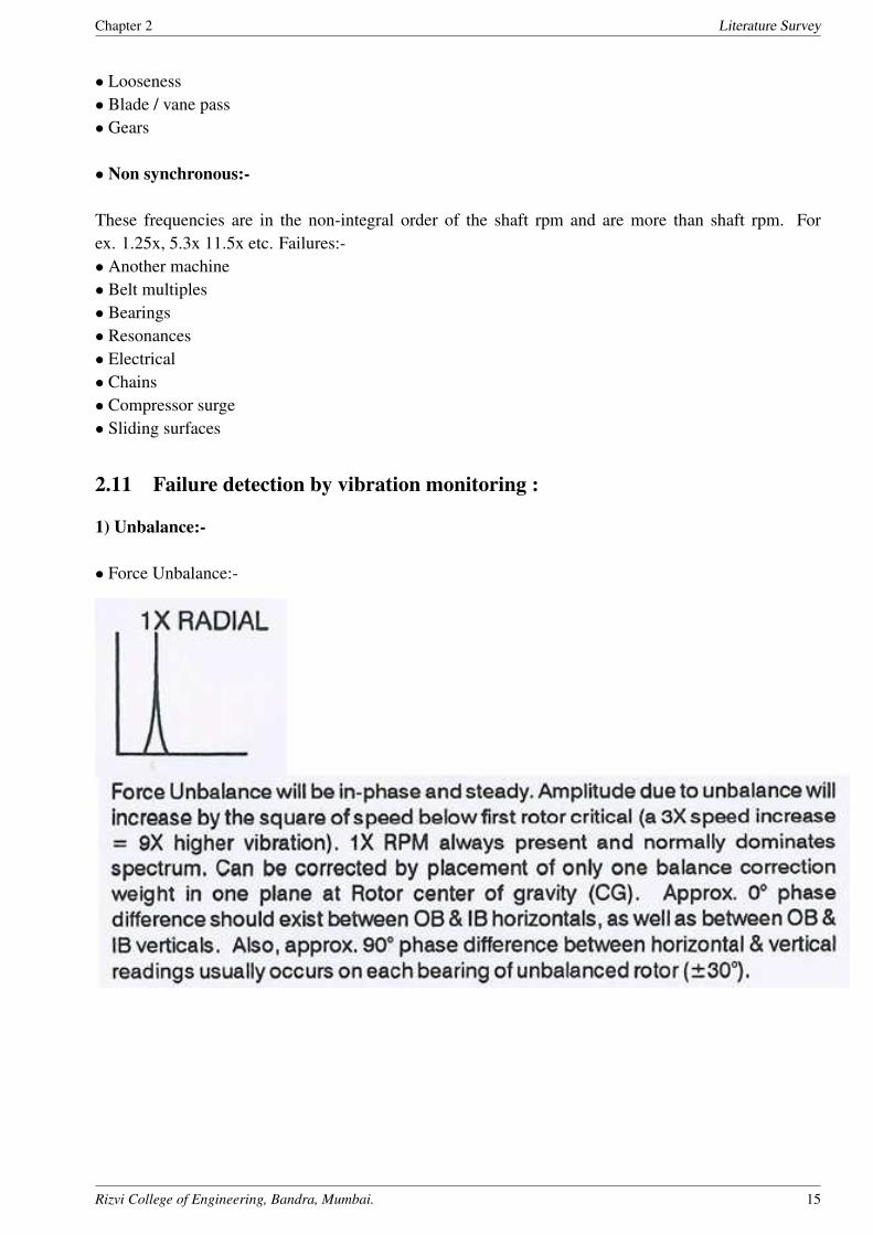
1) Unbalance:-
• Force Unbalance:-
Rizvi College of Engineering, Bandra, Mumbai. 15

Chapter 2 Literature Survey
• Couple Unbalance:-
• Dynamic Unbalance:-
2) Misalignment:-
• Angular misalignment:-
Rizvi College of Engineering, Bandra, Mumbai. 16

Chapter 2 Literature Survey
• Offset misalignment:-
3) Rotor Rub:-
Rizvi College of Engineering, Bandra, Mumbai. 17

Chapter 2 Literature Survey
4) Mechanical Looseness:-
Rizvi College of Engineering, Bandra, Mumbai. 18

Chapter 2 Literature Survey
5) Roller element bearings:-
Rizvi College of Engineering, Bandra, Mumbai. 19

Chapter 2 Literature Survey
Rizvi College of Engineering, Bandra, Mumbai. 20
Chapter 2 Literature Survey
2.12 Bearing failure parameters:-
• BPFI (ball pass inner race frequency):-
It is defined as the no. of rolling elements i.e. balls passing by any point on the inner race.
For ex: - if BPFI is 5.2 then in one revolution of the shaft, 5.2 balls are passed through a point on the
inner race.
Usually BPFI values are in the range of (4.8x to 11X).
If any defect is there on the inner race then it will be shown in the harmonics of BPFI value.
• BPFO (ball pass outer race frequency):-
It is defined as the no. of rolling elements passing by any point on the outer race.
For ex: - if BPFO is 3.5 then in one revolution of the shaft, 3.5 balls are passed through a point on the
outer race.
Range of BPFO values (2.5X to 6X).
If any defect is there on the outer race then it will be shown in the harmonics of BPFO value.
• BSF (ball spin frequency):-
It is defined as the no.of revolutions a ball makes about its own axis in one revolution of the shaft.
For ex: - if BSF is 2.3 then in one revolution of the shaft, every ball makes 2.3 revolutions about its own
axis.
Range of BSF values (2X to 3X).
If any defect is there on the rolling elements then it will be shown in the harmonics of BSF value.
• FTF (fundamental train frequency):-
Range of FTF values (0.4X to 0.6X).
The harmonics of FTF value are analyzed for bearing cage defects detection.
It is to be noted that
BPFI + BPFO = no.of rolling elements.
BPFI > BPFO > BSF > FTF
Peak view readings:-
• For bearing failure detection, peak view frequency readings are analyzed.
• Peak view readings are based on the Envelope Acceleration Technology.
• Peak view readings are used to detect bearing failures and cavitation problems, as both occur at high
frequencies.
• Peak view readings are collected only at bearing locations such as bearing housings.
• Peak view frequency > 60,000 RPM.
Rizvi College of Engineering, Bandra, Mumbai. 21

Chapter 2 Literature Survey
6) Bent shaft:-
7) Hydraulic and Aerodynamic forces:-
• Turbulent flow:-
Rizvi College of Engineering, Bandra, Mumbai. 22

Chapter 2 Literature Survey
• Cavitation:-
Rizvi College of Engineering, Bandra, Mumbai. 23

Chapter 2 Literature Survey
2.13 Case Study
2.13.1 Case Study of Pump 11P8B
Rizvi College of Engineering, Bandra, Mumbai. 24

Chapter 2 Literature Survey
Fasteners had entered the impeller. They got stuck on the impeller causing imbalance.
Impeller was pulled out and after cleaning was installed back. Vibration came down to 3 mm/sec.
Rizvi College of Engineering, Bandra, Mumbai. 25

Chapter 2 Literature Survey
2.13.2 Case Study of FD Fan SG9
Rizvi College of Engineering, Bandra, Mumbai. 26

Chapter 2 Literature Survey
• Frame foundation bolts were found loose.
• This was the case of Mechanical looseness.
• After tightening them, vibration came down to 6.4 mm/sec.
Rizvi College of Engineering, Bandra, Mumbai. 27

Chapter 2 Literature Survey
2.13.3 Case Study 12Fan1B
(Before bearing replacement)
(After bearing replacement)
Rizvi College of Engineering, Bandra, Mumbai. 28

Chapter 2 Literature Survey
2.14 Rotating Unbalance
What is unbalance?
• Rotating Unbalance is the uneven distribution of mass around an axis of rotation.
• Unbalance is caused when the center of mass (inertia axis) is out of alignment with the center of rota-
tion (geometric axis).
• When an object is forced to spin about a fixed axis, if the mass is not evenly distributed about that
fixed axis then we have unbalance.
• Unbalance causes a moment which gives an object the wobbling movement characteristic of the vibra-
tion of rotating structures.
Types of Unbalance:-
1. Static Unbalance
2. Couple unbalance
3. Dynamic unbalance
2.14.1 Static unbalance
In rotation, Due to unbalance when the mass/inertia axis is parallel to Shaft axis then it is called as Static
Unbalance. Single unbalance acting at the center of gravity is static unbalance. It occurs frequently in
disc-shaped rotors.
2.14.2 Couple unbalance:-
In rotation, Due to unbalance when the mass/inertia axis and the Shaft axis intersects on geometric cen-
ter axis then it is called a Couple Unbalance. Two equal and opposite unbalance acting at a distance b is
Static Unbalance. It occurs frequently in elongated cylindrical rotors.
2.14.3 Dynamic Unbalance
In rotation, Due to unbalance when the mass/inertia axis does not intersect with shaft axis then it is
called Dynamic Unbalance. Combination of static and couple unbalance is dynamic unbalance. It oc-
curs virtually in all rotors.
Effects of Unbalance:-
• Vibration
• Noise
• Decrease life of bearings
• Unsafe work conditions
• Reduced machine life
• Increased maintenance
Rizvi College of Engineering, Bandra, Mumbai. 29

Chapter 2 Literature Survey
2.15 Shaft Alignment
What is shaft alignment?
Deviation from a common centerline during operation.
Types of shaft misalignment:-
1. Offset misalignment:-
• Parallel horizontal misalignment:-
It occurs when the motor shaft is moved horizontally away from the pump shaft, but both shafts are still
in the same horizontal plane and parallel.
• Parallel vertical misalignment:-
It occurs when the motor shaft is moved vertically away from the pump shaft, but both shafts are still in
the same vertical plane and parallel.
Rizvi College of Engineering, Bandra, Mumbai. 30

Chapter 2 Literature Survey
2. Angular misalignment:-
• Angular horizontal misalignment:-
The motor shaft is under an angle with the pump shaft but both shafts are still in the same horizontal
plane.
• Angular vertical misalignment
The motor shaft is under an angle with the pump shaft but both shafts are still in the same vertical plane.
3. Combination of offset & angular misalignment:
Rizvi College of Engineering, Bandra, Mumbai. 31

Chapter 2 Literature Survey
Problems occur due to misalignment:-
• LOST PRODUCTION
• LEAKING SEALS
• INCREASED VIBRATION
• HIGHER ENERGY CONSUMPTION
• BEARING FAILURE
• SHAFT BREAKAGE
• COUPLING WEAR
• QUALITY PROBLEMS
Rizvi College of Engineering, Bandra, Mumbai. 32

Chapter 3 Proposed Work
Chapter 3
Proposed Work
3.1 Overhauling
The typical overhauling process of centrifugal pump involves checking the:-
• Pump shaft is straight and true to the bearings & seal housing.
• Bearing housing & fits are within tolerance.
• Wear ring clearances are within tolerance.
• Surface finish to shaft sleeves & their fits on the shaft.
• Impeller for erosion, cavitation, corrosion & the fit on the shaft.
• Condition & fit of all keys and keyways.
• Condition of stationary and rotating seals.
• Condition of bearings and lubricants.
• Casing for erosion, cavitation & corrosion.
• Condition of all fastners, seal-faces & gaskets.
• Balance of rotating assembly.
• Condition of the foundations and the holding down bolts.
• Pump , motor & pipe work alignment.
Figure 3.1: Overhauling
Rizvi College of Engineering, Bandra, Mumbai. 33

Chapter 3 Proposed Work
Removal of Pump for Inspection and Maintenance:-
1. Isolate pump electrical circuit breaker on main switch board and attach a warning notice.
2. Switch off and lock pumps supply at its local supply panel.
3. Close suction and discharge valves, chain and lock hand wheels.
4. Open pump suction and discharge pipe drain valves to bilge and when water ceases to flow; crack
open the pipes / pump flange joints carefully to ensure that pump has drained off and is safe for opening.
5. Fix a shackle to lifting pad eye above pump and hang chain block; ensuring SWL of block, slings and
shackles are satisfactory.
6. Use a center-punch to match/mark coupling and casing, then remove the coupling bolts.
7. Disconnect, fix i/d tag and remove motor supply cables; taping over bare ends with insulating tape.
8. Connect shackle and sling to motor eyebolt and lift motor clear of pump using overhead chain block.
Lay motor on its side out of harms way, protecting machined surfaces on both pump and motor coupling
halves against damage. (Cardboard and masking tape is quick and efficient method.)
9. Disconnect all external fittings from pump casing e.g. cooling pipe, pressure gauge, oil reservoirs and
air cock.
10. Remove bolting from top cover and remove cover. Scrape off old gasket and check mating surfaces,
and renew gasket on assembly. (Light smear of grease on gasket / faces)
11. The pump shaft with impeller can be lifted out of casing.
12. Dismantle the impeller, and remove the wear ring.
3.2 Pump Overhauling Procedure:
1. Drain out the lubricating oil from the bearing housing in a tray.
2. If the pump is used to pump thick (High viscosity) fluid such as Naphtha or toxic service pumps, then
Flush the inner surface of casing (including rotor assembly and other accessories) and outer surface of
the casing with water or high temperature steam.
3. Clean the pump thoroughly from outside.
4. Clamp the pump properly on the stand using E.O.T.
5. Remove the Casing cover.
6. Remove the impeller locknut and then remove the impeller using one of the following operations.
• Using hydraulic puller.
• By wedges using wedging action.
• By using hydraulic press.(application depends on size of the rotor)
• By heating inner surface of the impeller using LPG+Oxygen torch so that inner surface expands by
thermal means and impeller can be removed (Not Recommended).
7. Remove the stuffing box and mechanical seal.
8. Check the run out of the shaft.
9. Check the bearing condition and measure the axial & radial play of the bearing.
10. If any play found more than 0.003 i.e. (3 Thou), remove the coupling from the shaft.
11. Remove the shaft along with the bearings.
12. Note down the clearances.
13. Carry out thorough cleaning of all the parts.
14. Note down the physical conditions of all the parts as input to the failure analysis.
15. Check the trueness of the shaft. It should be within 0.00015 i.e. (1.5 Thou).
16. Check the bearing fit up at shaft & in housing.
Rizvi College of Engineering, Bandra, Mumbai. 34

Chapter 3 Proposed Work
17. Replace the Wear rings & throat bush if clearances are found more than desired value.
18. Lock the wear ring & maintain the clearance as specified by the vendor.
19. Refer to vibration report and carry out balancing of rotor if suggested.
20. Install the bearings using magnetic induction heater.
21. Install the shaft along with the bearings & tighten the covers.
22. Now check the axial float of the rotor. It should be within 0.002 i.e. (2 Thou).
23. Assemble the seal assembly insert on the shaft.
24. Assemble the impeller & stuffing box.
25. Tighten the impeller with torque wrench. Use the torque as specified by the vendor.
26. Insert the casing gasket & tighten the casing.
27. Hydro test the seal & casing for any leakage.
28. Attach the coupling.
29. Check all the casing nuts are tight.
30. Shift the pump at site.
31. Carry out housekeeping.
Flushing the pump with high temperature steam:-
If the pump is used to pump thick (High viscosity) fluid such as Naphtha or toxic service pumps, then
Flush the inner surface of casing (including rotor assembly and other accessories) and outer surface of
the casing with water or high temperature steam.
The above fig. shows the flushing of asphalt pump using high temp. Steam.
Figure 3.2: Steaming of pump
• After flushing, clean the pump from outside using oil.
• Always lock the mechanical seal before removing the casing from the pump. This is done by loosening
the Allen bolts and then turning the small metal plates provided, under the collar.
• This is to ensure that ,the two critical mating faces (carbon and hard face) of seal wont move relative
to each other and rub on each other while pump overhauling.
Rizvi College of Engineering, Bandra, Mumbai. 35

Chapter 3 Proposed Work
Figure 3.3: Seal
Clamping the pump on the table and removing casing cover:-
Removing the Impeller & mechanical Seal:-
Figure 3.4: removing casing coverl
Impeller can be removed by following methods:
1. Using hydraulic puller as shown in the fig. (Recommended method).
2. Using hydraulic press. (Preferred for large rotor especially for removing large F.D & I.D. fans from
the shaft).
3. Using wedging action with the help of wooden wedges. This is done by symmetrically inserting
triangular wedges in the gap between the impeller and the casing. (This method is not recommended as
it can harm the components).
4. Heating the I.D side surface by (LPG+Oxygen) heating torch so that the inner surface of the impeller
is thermally expanded and hence impeller can be removed. (Not recommended as it can thermally de-
formed the impeller of the shaft permanently).
Rizvi College of Engineering, Bandra, Mumbai. 36

Chapter 3 Proposed Work
(a) Removing impeller
(b) Hydraulic Press
Checking the Radial & Axial float:-
• Position the magnetic base of the dial indicator on the casing and position the tip of the indicator on the
circumference of the shaft. Then try to lift the shaft up by hands and note down the radial float readings.
• Now position the tip of the indicator on the center of the shaft so that probe axis is co-axial to the axis
of rotation of the shaft. Try to push and pull the shaft axially and note down the axial play readings.
• Ideally both the readings should be close to zero but some tolerance is allowed.
• If the float readings are more than acceptable range then the corresponding bearing should be replaced.
Figure 3.6: hydraulic press
Rizvi College of Engineering, Bandra, Mumbai. 37

Chapter 3 Proposed Work
Removing the coupling & removing the rotor from pump casing:-
• The coupling should be removed using hydraulic puller. These pullers come with different pres-
sure capacities and different lengths of the forks. Choosing the right puller is also important. Attach the
forks on the coupling flange and position the center piston on the center of the shaft so that after pushing
the piston by hydraulic force, the forks will pull the coupling out.
Removing lock nut & lock washer:-
• Lock nut with lock washer is used to prevent the bearings from sliding over the shaft.
• The lock washer is also called as star washer as it has protrusions all over its circumference.
• The lock nut also has a corresponding groove so that one of the protrusions of the washer can fit into
the groove.
• When one of the protrusions is fitted in the groove, it is bent down to lock the nut & washer assembly.
• It is to be noted that the lock nut is loosened by rotating it in the same direction of the shaft .This is
due to the fact that whenever an obstruction comes between the shafts the lock nut tends to tighten itself
there by justifying its purpose.
Rizvi College of Engineering, Bandra, Mumbai. 38

Chapter 3 Proposed Work
Removing the bearings:-
• Cantilever pumps usually have one radial bearing at impeller side and two oppositely positioned an-
gular contact roller bearing (Axial bearing) at motor side.
• Bearings are tight fitted with interference fit hence before removing them we have to make sure that
they must be replaced.
• There are two methods of removing the bearings.
• Using punch and hammer.
• Heating the inner race of the bearing with the heating torch.
• Once the bearing is removed, it has to be replaced.
Checking the Shaft for bents (Trueness check):-
• Mount the shaft on the lathe.
• Checking for trueness is done using dial gauge indicator.
• Dial gauge is usually positioned at three points along the shafts.
• Near the chuck
• In the middle of the shaft
• At the other end of the shaft
• First, place the dial gauge near the chuck and rotate the shaft once. If any deflection is there then adjust
the shaft with the help of chuck to make it perfectly co-axial. Repeat the step till the dial shows zero
reading.
• Place the dial gauge in the middle and rotate the shaft once. If any deflection is shows then the shaft
may be bent or the shaft is not co-axial. Hence try to adjust the chuck till the dial shows near to zero
reading.
• Place the dial gauge at the end and rotate the shaft. If again the deflection is observed then the shaft is
bent for sure.
Rizvi College of Engineering, Bandra, Mumbai. 39

Chapter 3 Proposed Work
Wear rings:-
Above fig shows the acceptable clearances for wear rings.
Rizvi College of Engineering, Bandra, Mumbai. 40
Chapter 3 Proposed Work
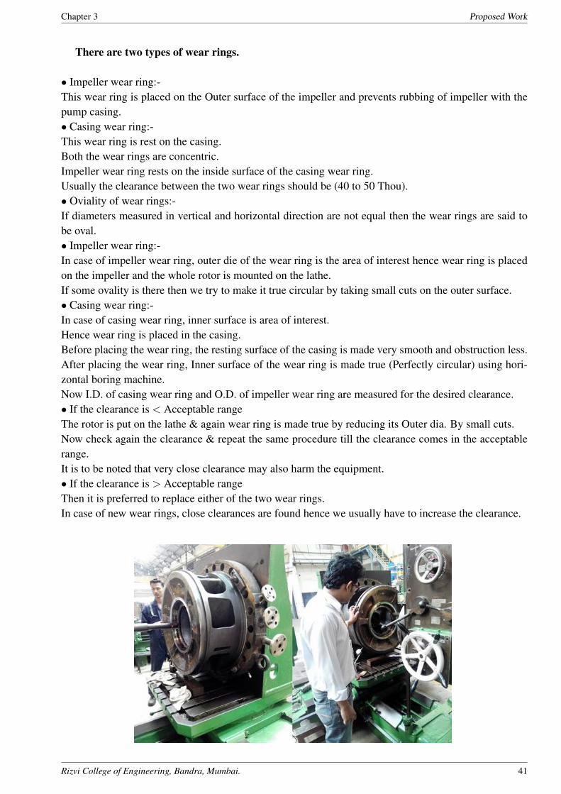
There are two types of wear rings.
• Impeller wear ring:-
This wear ring is placed on the Outer surface of the impeller and prevents rubbing of impeller with the
pump casing.
• Casing wear ring:-
This wear ring is rest on the casing.
Both the wear rings are concentric.
Impeller wear ring rests on the inside surface of the casing wear ring.
Usually the clearance between the two wear rings should be (40 to 50 Thou).
• Oviality of wear rings:-
If diameters measured in vertical and horizontal direction are not equal then the wear rings are said to
be oval.
• Impeller wear ring:-
In case of impeller wear ring, outer die of the wear ring is the area of interest hence wear ring is placed
on the impeller and the whole rotor is mounted on the lathe.
If some ovality is there then we try to make it true circular by taking small cuts on the outer surface.
• Casing wear ring:-
In case of casing wear ring, inner surface is area of interest.
Hence wear ring is placed in the casing.
Before placing the wear ring, the resting surface of the casing is made very smooth and obstruction less.
After placing the wear ring, Inner surface of the wear ring is made true (Perfectly circular) using hori-
zontal boring machine.
Now I.D. of casing wear ring and O.D. of impeller wear ring are measured for the desired clearance.
• If the clearance is < Acceptable range
The rotor is put on the lathe & again wear ring is made true by reducing its Outer dia. By small cuts.
Now check again the clearance & repeat the same procedure till the clearance comes in the acceptable
range.
It is to be noted that very close clearance may also harm the equipment.
• If the clearance is > Acceptable range
Then it is preferred to replace either of the two wear rings.
In case of new wear rings, close clearances are found hence we usually have to increase the clearance.
Rizvi College of Engineering, Bandra, Mumbai. 41

Chapter 3 Proposed Work
Clearance measurement:-
Clearances are measured in HPCL using two methods:
• Using shim gauge
• Using Plastic gauge
Shim gauge:-
Shims are very thin but precisely made metal strips .These are used to measure clearances & adjustment
of motors in alignment procedure.
Rizvi College of Engineering, Bandra, Mumbai. 42

Chapter 3 Proposed Work
Plastic precision clearance gauge:-
Rizvi College of Engineering, Bandra, Mumbai. 43

Chapter 3 Proposed Work
The above fig. shows the usage of plastigauge for checking clearance in split bearing of a fan.
In HPCL, ideal bearing clearance is from 1 to 1.5 Thou.
Clearance less than 1 Thou or greater than 1.5 Thou is not acceptable.
This is due to the fact that, for proper working of bearing and long life of bearing, the bearing clearance
is very critical parameter.
Less or more clearance than the specified range may results into
• If the clearance is more, the outer race will tend to rotate inside the upper bearing cover.
• Due to less clearance, there is a pressure on the whole bearing which results in the rubbing of rolling
balls against inner and outer race which not only decreases bearing life but also generates heat.
• If the clearance is more then there is a space for bearing vibration.
• If the clearance is less then, this may result into the ovality of the bearing due to pressure exerted by
bearing cover.
Results of split bearing clearance between I.D of bearing cover and O.D of outer race of the bear-
ing = Clearances of both the bearings are found to be (0.25 Thou)less than 1 Thou which is not
acceptable.
Solution= adding 2 thou shims under the bearing cover to increase the clearance. This method
for checking the clearance is especially used for checking the clearance of split bearings & in the
situation where shim gauges cannot be inserted.
This method is useless where there is no place for the plastigauge to attach or where its not possible
to detach one of the mating surfaces without disturbing the plastigauge. For example: - checking the
clearance between casing wear ring and impeller wear ring.
3.3 Overhauling of mechanical seal:-
Mechanical seal is the most critical components of centrifugal pumps.
Almost everywhere where pumps with rotating shafts are used, a shaft seal is involved
The shaft seal forms a barrier between what is inside the pump and the atmosphere.
Rizvi College of Engineering, Bandra, Mumbai. 44

Chapter 3 Proposed Work
There are countless variants of shaft seals, reflecting the diversity of the pump industry, and the need for
specific solutions for individual situations. In its most basic form, a shaft seal combines a rotating part
with a stationary part. When properly designed and installed, the rotating part rides on a lubricating film,
only 0.00025 mm in thickness. Should the film become too thick, the pumped medium will leak. If the
film becomes too thin, the friction loss increases and the contact surfaces overheat, triggering seal failure.
Sleeve:-
It is a hollow cylindrical component which fits on
the shaft and protects the shaft from rubbing.
It is the rotating component of the seal.
It also supports collar and retainer to hold fixed
mating surface.
when the seal is disembled for inspection, first the
sleeve along with all rotating components are re-
moved from the gland.
Rizvi College of Engineering, Bandra, Mumbai. 45

Chapter 3 Proposed Work
Gland:- Gland is the fixed component of the mechanical seal.
It is attached to the pump casing by means of bolts.
It supports all the fixed components of the seal.
It contains many steps as shown in the the fig. to place o-rings in it to prevent leakage from various
corners.
On top of it, there are usually 4 thin metal srtips which are used to lock the sleeve from rotating, by
lifting the collar while seal overhauling.
On the circumference of the gland, there are 3 pipe mounting holes with threadings on the inner side.
Two holes are on one side and are referred to as
B.I.-buffer inlet
D-drain
The third hole is on the opposite side of the two holes and is referred to as
B.O.- buffer outlet
B.I and B.O are used to connect required seal lubrication/cooling system as per the API plan for the
pump.
Drain is used to detect seal leakage.
Whenever there is seal leakage, the fluid will leak through drain and hence can be easily seen by pump
operator.
Rizvi College of Engineering, Bandra, Mumbai. 46

Chapter 3 Proposed Work
Collar and retainer:-
Collar is a hollow thin cylindrical component which is mainly used to attach the sleeve with the shaft
with the help of grub screws. Grub srew grabs the sleeve with the rotating shaft.
Retainer is a cup shaped component which is used to hold the carbon face (Rotating face) pressed against
the helical springs or leaf springs attached in the retainer. The sleeve properly sits inside the retainer on
the step provided on both.
In small pumps , the retainer is replaced by bellows.
During overhauling, the springs are checked for their good condition and stiffness.
In some of the pump seals, we found these springs are broken down by over use and corrosion.
Rizvi College of Engineering, Bandra, Mumbai. 47

Chapter 3 Proposed Work
Mating surfaces and 0-rings:-
These are the actual sealing components of the mechanical seal.
In a single seal, there is 1 mating surface pair , ie. Two mating surfaces.
One is called hard face and other is called carbon face.
In double seal, there are two mating surface pairs .
The reason for using two different materials for the rubbing surfaces is that, these surfaces rub against
each other leaving no gap for any fluid leakage. But because of the rubbing, they wear out.
The cost of the faces is very high goin even upto 1 to 1.5 lakhs for a single surface. If we use one soft
and one hard material for the faces then there will be rubbing of only soft surface and hence only carbon
needs to be replaced.
O ring:-
These are called o-rings because there cross section is circular.
An o-ring is made up of specialized elastomer such as (Viton)
It is used for sealing the leakage from corners and steps.
O-rings are designated by I.D (inner dia) x wire diameter.
For example:- if I.d is 50mm and wire diameter is 5 mm then it is designated by 50 x 5.
Rizvi College of Engineering, Bandra, Mumbai. 48

Chapter 3 Proposed Work
Case study:-
• Pump tag no:- 103P1001B
• Pumping fluid:- Naptha
• Seal arrangement:- Seal at both ends.
Observation:-
Both seals leaked after 8 minutes from starting the pump.
Observation after opening the seal:-
1. Rubbing marks on sleeve rendering it useless.
2. Hard seal face is completely broken.
3. O-Ring of carbon face is burnt and become semi-circular is cross section.
4. Carbon face is also broken.
Rizvi College of Engineering, Bandra, Mumbai. 49

Chapter 3 Proposed Work
Rizvi College of Engineering, Bandra, Mumbai. 50

Chapter 3 Proposed Work
Conclusion from the observation of damage:-
The pump is led to dry run .
Possible Reasons for dry run:-
1. Lack of seal lubrication
2. Insufficient suction pressure
3. Cavitation
After inspection of process for starting of the pump:-
It is found that the dry run of pump is caused by suddenly starting the pump without partially closing
the delivery valves of the this pump and the other pump on the same line.
There are always two pumps in parallel arrangement at each pump site. One is kept stand by, so that if
one pump needs to be overhauled then the other pump can start without discontinuing the whole plant.
It is to be noted that when starting the stand by pump and stopping the currently running pump, the
delivery valve of running pump is partially closed so that newly starting pump gets sufficient suction .
Then slowly the delivery valve of starting pump is opened and simultaneously the delivery valve of clos-
ing pump is slowly close in order to give sufficient suction to starting pump.
But in this case, the pump is directly started without closing the delivery valve of the running pump.As
a result the pump didnt get enough suction and hence it couldnt suck suffient fluid so it run dry.
Rizvi College of Engineering, Bandra, Mumbai. 51

Chapter 3 Proposed Work
Overhauling of the damaged seal:-
1. The sleeve is damged severly hence it cant be used anymore.Hence it is replaced and checked for
proper clearance.
2. Both the seal faces (hard face and carbon face) are replaced.
3. All wear rings are replaced.
4. Collar and retainer are not damaged hence no need to replace.
5. All scrub screws are intact.
6. Some of the retainer springs were found broken hence they are replaced.
7. All the components are properly cleaned,checked for proper fit and then assembled.
8. Hydrotest is done on both the seals and they were ready for the use.
9. Installed the seals on the pump and assemble the pump.
10 . Install the pump properly in the plant and laser alignment is done.
11 . It was make sure that while starting the pump, all the procedure is strictly followed under the super-
visor.
Rizvi College of Engineering, Bandra, Mumbai. 52
Chapter 3 Proposed Work
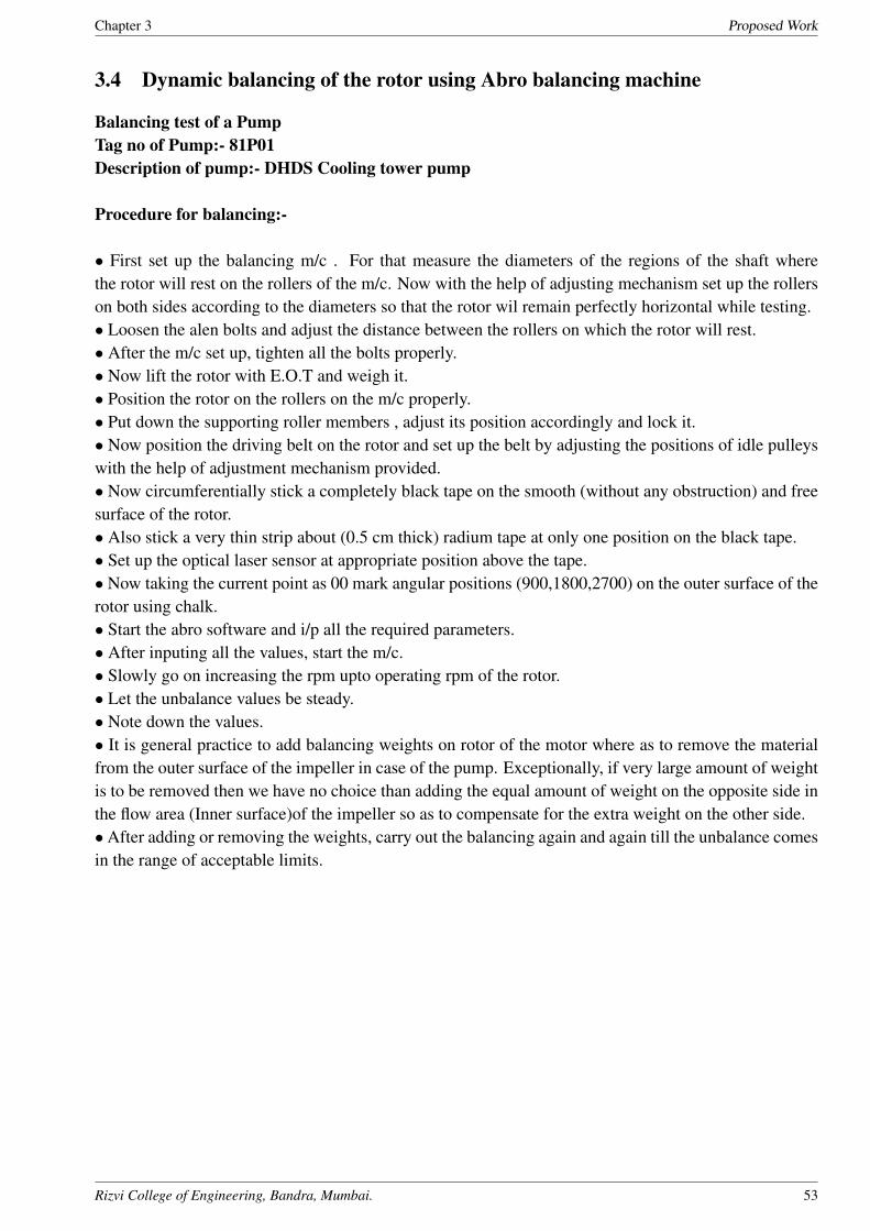
3.4 Dynamic balancing of the rotor using Abro balancing machine
Balancing test of a Pump
Tag no of Pump:- 81P01
Description of pump:- DHDS Cooling tower pump
Procedure for balancing:-
• First set up the balancing m/c . For that measure the diameters of the regions of the shaft where
the rotor will rest on the rollers of the m/c. Now with the help of adjusting mechanism set up the rollers
on both sides according to the diameters so that the rotor wil remain perfectly horizontal while testing.
• Loosen the alen bolts and adjust the distance between the rollers on which the rotor will rest.
• After the m/c set up, tighten all the bolts properly.
• Now lift the rotor with E.O.T and weigh it.
• Position the rotor on the rollers on the m/c properly.
• Put down the supporting roller members , adjust its position accordingly and lock it.
• Now position the driving belt on the rotor and set up the belt by adjusting the positions of idle pulleys
with the help of adjustment mechanism provided.
• Now circumferentially stick a completely black tape on the smooth (without any obstruction) and free
surface of the rotor.
• Also stick a very thin strip about (0.5 cm thick) radium tape at only one position on the black tape.
• Set up the optical laser sensor at appropriate position above the tape.
• Now taking the current point as 00 mark angular positions (900,1800,2700) on the outer surface of the
rotor using chalk.
• Start the abro software and i/p all the required parameters.
• After inputing all the values, start the m/c.
• Slowly go on increasing the rpm upto operating rpm of the rotor.
• Let the unbalance values be steady.
• Note down the values.
• It is general practice to add balancing weights on rotor of the motor where as to remove the material
from the outer surface of the impeller in case of the pump. Exceptionally, if very large amount of weight
is to be removed then we have no choice than adding the equal amount of weight on the opposite side in
the flow area (Inner surface)of the impeller so as to compensate for the extra weight on the other side.
• After adding or removing the weights, carry out the balancing again and again till the unbalance comes
in the range of acceptable limits.
Rizvi College of Engineering, Bandra, Mumbai. 53

Chapter 3 Proposed Work
Rizvi College of Engineering, Bandra, Mumbai. 54

Chapter 3 Proposed Work
Inputs given to abro software for balancing of pump 81P01:-
Rotor type =7
A= 0 mm
B= 1190 mm
C =0 mm
RL= 290 mm
RR=290 mm
Balancing speed =800 rpm
Rounf off (L)= 0.01
Round off(R)=0.01
Tolerance (L)=10.7 gm
Tolerance (R)=10.7gm
Offset angle = 00
Correction method= Remove
(L,R)
Correction mode= Polar (L,R)
Rizvi College of Engineering, Bandra, Mumbai. 55

Chapter 3 Proposed Work
Reading no. 1
After removing some material with the help of portable grider.
Reading no.2
As weight to be removed is more hence we decided to add weight of 35.58 gms on opposite side
i.e 289-180= 1090
we added approx. 36 gms
Rizvi College of Engineering, Bandra, Mumbai. 56

Chapter 3 Proposed Work
Reading no. 3:-
On the inspection, we found
that there is left over weld-
ing material of previous
wledings added for balanc-
ing. Hence we grinded and
removed the material and
again checked.
Reading no.4 :-
Now instead of adding 11
gms it is easier to remove it
at 2590 by grinding.
Final Reading:-
Since the unbalance reading is in tolerance hence the rotor is said to be balance.
Rizvi College of Engineering, Bandra, Mumbai. 57

Chapter 3 Proposed Work
3.5 Hydrotest of seals
Need for hydro test:-
• The purpose of a mechanical seal is to prevent leakage but all seals leak to some controlled degree.
• However, it is important to note that this minimal leakage can be so restricted that specific designs are
capable of adequately meeting all emission requirements.
• Seal failure is defined as excessive leakage. The seal can be described as a controlled leakage device
represented by two nonporous, plane, parallel walls separated by a distance h, the seal face separation.
Assuming constant physical properties and laminar, incompressible flow, the leakage rate is proportional
to the pressure and to the cube of the face separation.
• As the name suggests, hydrotest is the test carried out to check leakage failure especially in mechanical
seals.
Leakage Sources:-
In most cases, the seal leakage comes from the sealing interface. However, in some situations, leakage
may come from the secondary sealing area, such as O-rings. This could be due to O-ring degradation
caused by chemical attack, overheating and loss of resilience from compression set. In rare occasions,
the sealing rings are porous and fluid leaks through the bodies. The above leakage problems can be
identified with static pressurization.
Techniques for hydro tests:-
• Hydro test can be carried out by
1. Mounting the mechanical seal onto the specifically designed hydro test setup.
2. Assembling the seal on the pump and then carrying hydro test.
• Hydro test setup is preferred as seal can be easily repaired as it is not yet installed on the pump.
Hydro test of single seal after assembling it on the pump:-
1. Block the drain.
2. Block the suction inlet and discharge outlet using proper size blanks but dont tighten the blanks. Keep
on of the blank slightly open.
3. Attach the supply water pipe to drain outlet of the pump and fill the casing completely till the water
comes out of from the open outlet. Now stop the flow of water and tighten all the blanks.
4. Now stop the water supply and start air supply through the same line. The air pressure should be up
to (5kg/cm2).
5. Check for any leakage through BI (buffer inlet) or BO (buffer outlet).
Rizvi College of Engineering, Bandra, Mumbai. 58

Chapter 3 Proposed Work
Hydro test of double seal:-
Checking Primary seal:-
1. Block the drain.
2. Fill the tank and seal with water.
3. Then stop the water supply and start air supply by the same line. Air pressure should be 5kg/cm2.
4. Check for air or water leakage through BI or BO. Generally seal will leak through BO.
Checking the secondary seal:-
1. Let the air pressure be same in the tank.
2. Open the drain D.
3. Connect one more supply line to BI (buffer inlet).
4. Start water supply till the water comes out from BO.
5. Stop water supply.
6. Through the same line supply pressurized air (1.5 to 2.5 kg/cm2).
7. Check the leakage of air or water through drain D or from collar side.
Rizvi College of Engineering, Bandra, Mumbai. 59
Chapter 3 Proposed Work
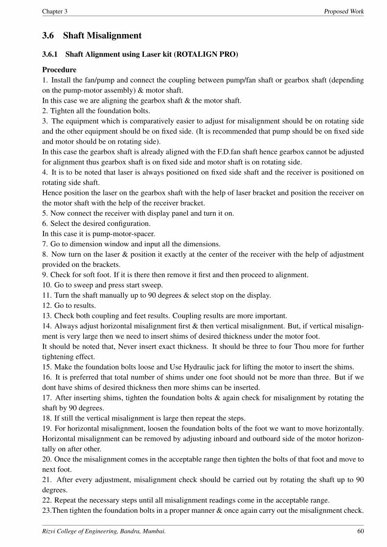
3.6 Shaft Misalignment
3.6.1 Shaft Alignment using Laser kit (ROTALIGN PRO)
Procedure
1. Install the fan/pump and connect the coupling between pump/fan shaft or gearbox shaft (depending
on the pump-motor assembly) & motor shaft.
In this case we are aligning the gearbox shaft & the motor shaft.
2. Tighten all the foundation bolts.
3. The equipment which is comparatively easier to adjust for misalignment should be on rotating side
and the other equipment should be on fixed side. (It is recommended that pump should be on fixed side
and motor should be on rotating side).
In this case the gearbox shaft is already aligned with the F.D.fan shaft hence gearbox cannot be adjusted
for alignment thus gearbox shaft is on fixed side and motor shaft is on rotating side.
4. It is to be noted that laser is always positioned on fixed side shaft and the receiver is positioned on
rotating side shaft.
Hence position the laser on the gearbox shaft with the help of laser bracket and position the receiver on
the motor shaft with the help of the receiver bracket.
5. Now connect the receiver with display panel and turn it on.
6. Select the desired configuration.
In this case it is pump-motor-spacer.
7. Go to dimension window and input all the dimensions.
8. Now turn on the laser & position it exactly at the center of the receiver with the help of adjustment
provided on the brackets.
9. Check for soft foot. If it is there then remove it first and then proceed to alignment.
10. Go to sweep and press start sweep.
11. Turn the shaft manually up to 90 degrees & select stop on the display.
12. Go to results.
13. Check both coupling and feet results. Coupling results are more important.
14. Always adjust horizontal misalignment first & then vertical misalignment. But, if vertical misalign-
ment is very large then we need to insert shims of desired thickness under the motor foot.
It should be noted that, Never insert exact thickness. It should be three to four Thou more for further
tightening effect.
15. Make the foundation bolts loose and Use Hydraulic jack for lifting the motor to insert the shims.
16. It is preferred that total number of shims under one foot should not be more than three. But if we
dont have shims of desired thickness then more shims can be inserted.
17. After inserting shims, tighten the foundation bolts & again check for misalignment by rotating the
shaft by 90 degrees.
18. If still the vertical misalignment is large then repeat the steps.
19. For horizontal misalignment, loosen the foundation bolts of the foot we want to move horizontally.
Horizontal misalignment can be removed by adjusting inboard and outboard side of the motor horizon-
tally on after other.
20. Once the misalignment comes in the acceptable range then tighten the bolts of that foot and move to
next foot.
21. After every adjustment, misalignment check should be carried out by rotating the shaft up to 90
degrees.
22. Repeat the necessary steps until all misalignment readings come in the acceptable range.
23.Then tighten the foundation bolts in a proper manner & once again carry out the misalignment check.
Rizvi College of Engineering, Bandra, Mumbai. 60

Chapter 3 Proposed Work
Rizvi College of Engineering, Bandra, Mumbai. 61

Chapter 3 Proposed Work
Laser alignment coupling results for F.D. (Forced draft) Fan of new boiler house:-
In HPCL Refinery ,the acceptable range for alignment of shaft for coupling readings: -
-5 Thou to +5 Thou
Before laser alignment:-
Vertical: - Inboard=10.25 Outboard= 7.4
Horizontal: - Inboard= 5.3 Outboard= 9.45
After laser alignment:-
Vertical: - Inboard= 3.1 Outboard= 0.7
Horizontal: - Inboard= 1.1 Outboard= -3.3
Rizvi College of Engineering, Bandra, Mumbai. 62
Chapter 3 Proposed Work
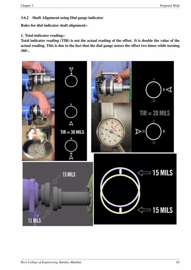
3.6.2 Shaft Alignment using Dial gauge indicator
Rules for dial indicator shaft alignment:-
1. Total indicator reading:-
Total indicator reading (TIR) is not the actual reading of the offset. It is double the value of the
actual reading. This is due to the fact that the dial gauge senses the offset two times while turning
360◦.
Rizvi College of Engineering, Bandra, Mumbai. 63
Chapter 3 Proposed Work
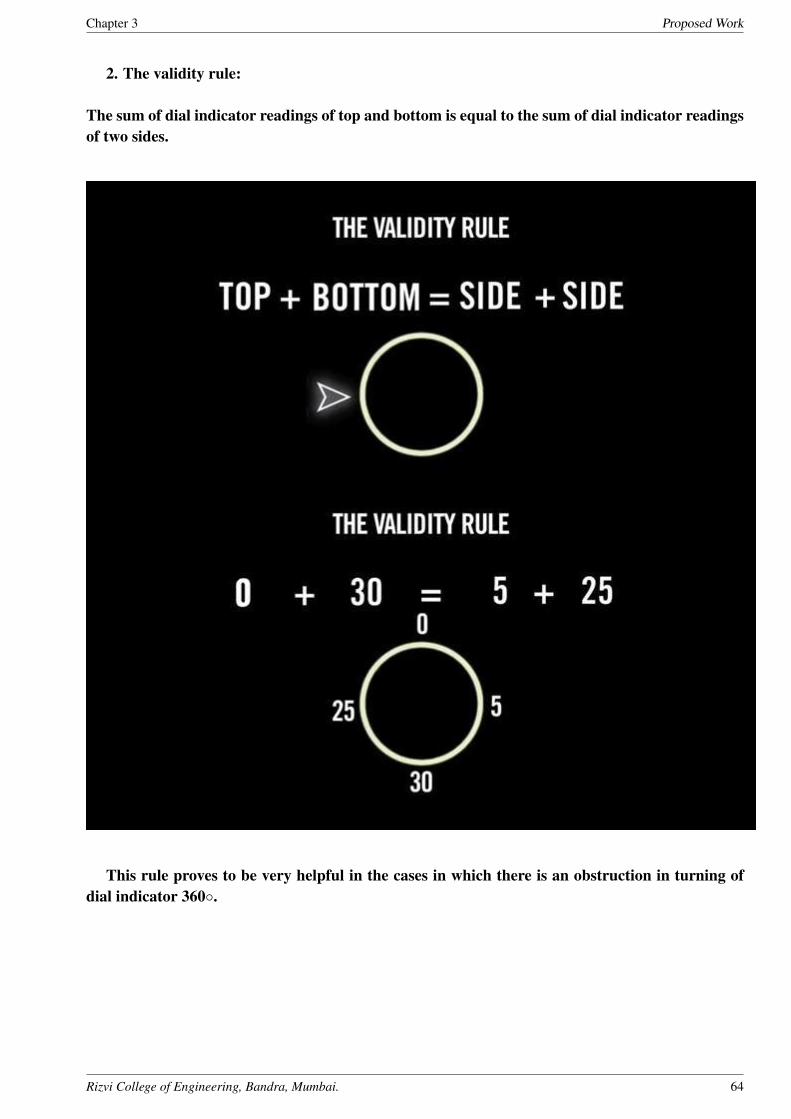
2. The validity rule:
The sum of dial indicator readings of top and bottom is equal to the sum of dial indicator readings
of two sides.
This rule proves to be very helpful in the cases in which there is an obstruction in turning of
dial indicator 360◦.
Rizvi College of Engineering, Bandra, Mumbai. 64

Chapter 3 Proposed Work
3. True position sensing:-
• At the top position set the dial at 0◦.
• Rotate the shaft along with dial gauge through 360◦ and mark dial readings at 90◦ , 180◦ &
270◦.
• Now At any position, If we set the dial indicator reading to half of the value of the reading shown
by it at the same postion, then it shows true (Actual) offset readings at all the positions ie. 0◦, 90◦
, 180◦ & 270◦.
Rizvi College of Engineering, Bandra, Mumbai. 65

Chapter 3 Proposed Work
Procedure for shaft alignment using dial indicator:-
1. Install the pump properly on the foundation and make sure all the foundation bolts of pump are
properly tight.
2. Two types of shaft misalignments are removed by this method.
3. Always angular alignment of shaft is done first and then radial (Offset) misalignment is done.
4. Initially shaft coupling is not attatched.
5. Position the magnetic base of the dial gauge on the coupling flange of the pump shaft.
6. The base should rest on the front surface where the coupling will attach afterwards.
7. Now touch the pointer of the indicator to the corresponding surface of the flange of the motor shaft.
8. Set the current position as 0 in the dial.
9. Rotate the shaft slowly and mark the readings at 90◦, 180◦ and 270◦.
10. Thses are total indicator readings(TIR).
11. For adjusting flange surface of motor with that of pump,
the thickness of shims to be added or removed = 3 * bottommisalignment reading. 12. Add or remove
required amout of shims thus remove angular misalignment.
13. Now position the base of the dial gauge on the circumference of the the coupling flange of the pump
shaft.
14. Touch the pointer of the dial gauge to the corresponding surface of the flange of the motor shaft.
15. At top position, set the dial at zero.
16. Rotate the pump shaft through 360◦ and mark dial readings at 90◦, 180◦ and 270◦.
17. Add or remove the required amount of shims thus removing the radial misalignment.
Rizvi College of Engineering, Bandra, Mumbai. 66

Chapter 3 Proposed Work
Rizvi College of Engineering, Bandra, Mumbai. 67
Chapter 3 Proposed Work
The given fig. shows the Aixial (angular) and Radial (offset) misalignment values of an asphalf pump.
Dial gauge radings of the pump:-
Axial:- (in Thou)
• Top:- 0
• Bottom:- -6
• Right:- -7
• Left:- +1
Radial:- (in Thou)
• Top:- 0
• Bottom:- +60
• Right:- -10
• Left:- +70
Rizvi College of Engineering, Bandra, Mumbai. 68

Chapter 3 Proposed Work
3.7 Dye Penetration test
The visible dye penetrant inspection process detects surface connected cracks and Other flaws, such as
laps and pores in all metals, as well as in most plastics and Ceramics. It is widely used for determining
the integrity of a weld. Through dye penetrant inspection, cracks are revealed as vivid red lines on a
white Background.
The process consists of:
(1) Applying a liquid, red dye penetrant which seeks out and enters surface flaws,
(2) Removing the red dye penetrant that did not enter a defect, and
(3) Spraying on a white developer.
Three materials are used in the process:
(1) Pink/Red dye penetrant
(2) Cleaner/Remover
(3) Developer
Rizvi College of Engineering, Bandra, Mumbai. 69

Chapter 3 Proposed Work
Pressurized spray cans are the most commonly used package. The cans are easily Carried to the part
to be inspected. There are no brushes to clean; no spillage. Plus, Spray cans protect inspection materials
from contamination. Dye penetrant can be sprayed on a limited area of a part, such as a weld or critical
Section. It can be removed by wiping with a dry towel or a towel dampened with Cleaner/Remover. In
the case of water-washable dye penetrant, it can be removed with A water-dampened towel or by water
spray. The developer is always applied by spraying.
Five basic operations:-
Rizvi College of Engineering, Bandra, Mumbai. 70
Chapter 3 Proposed Work
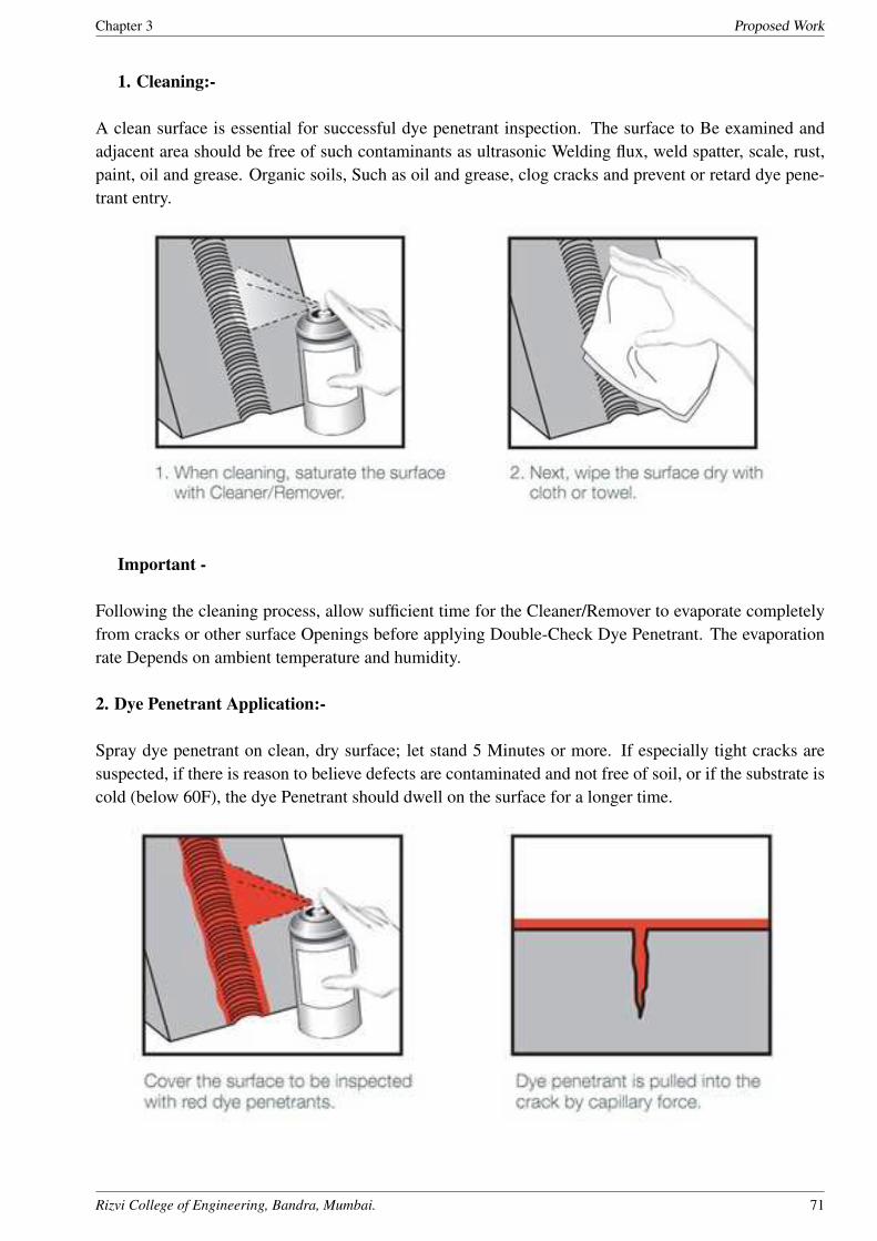
1. Cleaning:-
A clean surface is essential for successful dye penetrant inspection. The surface to Be examined and
adjacent area should be free of such contaminants as ultrasonic Welding flux, weld spatter, scale, rust,
paint, oil and grease. Organic soils, Such as oil and grease, clog cracks and prevent or retard dye pene-
trant entry.
Important -
Following the cleaning process, allow sufficient time for the Cleaner/Remover to evaporate completely
from cracks or other surface Openings before applying Double-Check Dye Penetrant. The evaporation
rate Depends on ambient temperature and humidity.
2. Dye Penetrant Application:-
Spray dye penetrant on clean, dry surface; let stand 5 Minutes or more. If especially tight cracks are
suspected, if there is reason to believe defects are contaminated and not free of soil, or if the substrate is
cold (below 60F), the dye Penetrant should dwell on the surface for a longer time.
Rizvi College of Engineering, Bandra, Mumbai. 71

Chapter 3 Proposed Work
Rizvi College of Engineering, Bandra, Mumbai. 72
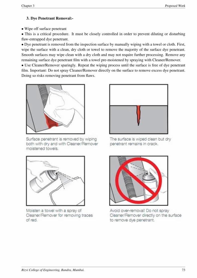
Chapter 3 Proposed Work
3. Dye Penetrant Removal:-
• Wipe off surface penetrant
• This is a critical procedure. It must be closely controlled in order to prevent diluting or disturbing
flaw-entrapped dye penetrant.
• Dye penetrant is removed from the inspection surface by manually wiping with a towel or cloth. First,
wipe the surface with a clean, dry cloth or towel to remove the majority of the surface dye penetrant.
Smooth surfaces may wipe clean with a dry cloth and may not require further processing. Remove any
remaining surface dye penetrant film with a towel pre-moistened by spraying with Cleaner/Remover.
• Use Cleaner/Remover sparingly. Repeat the wiping process until the surface is free of dye penetrant
film. Important: Do not spray Cleaner/Remover directly on the surface to remove excess dye penetrant.
Doing so risks removing penetrant from flaws.
Rizvi College of Engineering, Bandra, Mumbai. 73

Chapter 3 Proposed Work
4. Developer Application:-
• Before applying developer, vigorously shake the spray can to restore fully the white developer particle
suspension. Spraying is the ONLY recommended method of applying developer.
• The goal is to spray a light, even coat which is slightly damp when it contacts the surface. It should
be slightly damp, so the volatile solvent will couple the flaw-entrapped dye penetrant to the powder and
speed the penetrants return to the surface for viewing.
• But, it should not be so damp as to dilute and over spread the small amount of dye penetrant retained
in the flaw. A too damp developer application results in weak, blurred indications.
Rizvi College of Engineering, Bandra, Mumbai. 74

Chapter 3 Proposed Work
5. Inspection (Flaw Reading):-
• Allow time for flaw indications to appear completely.
• As soon as the developer has dried, indications of flaws (if present) will appear. However, it is sug-
gested that an additional 5 minutes, or longer, be allowed for indications to reach their full pattern prior
to final visual examination and indication interpretation. The need for a longer developing time is essen-
tial if extremely tight cracks are suspected. Some types of flaws re-bleed profusely, and monitoring the
surface during the developing time assists in correctly interpreting the characteristics of the flaw. The
rate of bleed back, depth of colour, as well as the indication pattern clues the inspector as to the defect
type.
• Red lines indicate cracks, laps or lack of fusion. Tight cracks may appear as dots in a line or curve.
Porosity appears as scattered red dots.
• The criteria for rejecting a part are usually determined by design engineers. Not all flaws may be cause
for rejection. Size, location, and type of indication, as well as a parts Eventual use and work load will
influence the rejection criteria.
Rizvi College of Engineering, Bandra, Mumbai. 75
Chapter 3 Proposed Work
Inspection results:-
A crack is found near the step on the shaft of F.D.fan.
The crack is continuous in nature hence it is relatively large crack.
Conclusion and Final decision:-
The crack is severe hence the shaft needs to be replaced.
Reasons for shaft rejection:-
• The crack is present at a very critical position i.e. near the step at bearing region.
• The size of the crack is large and can be grown during the continued service.
• The crack is causing vibrations in bearing housing.
• The F.D. fan is a critical component hence it is not economical to repair the fan frequently if the crack
is repaired by welding.
Rizvi College of Engineering, Bandra, Mumbai. 76

Chapter 4 Implementation & Technologies Used in HPCL
Chapter 4
Implementation & Technologies Used in
HPCL
1. CSI 2130 Machinery health monitor
2. Abro dynamic balancing machine
(a) Abro dynamic balancing machine
Rizvi College of Engineering, Bandra, Mumbai. 77

Chapter 4 Implementation & Technologies Used in HPCL
3. Spot radiometer (temperature gun)
4. Dedicated Machine workshop
Rizvi College of Engineering, Bandra, Mumbai. 78

Chapter 4 Implementation & Technologies Used in HPCL
5. Laser Alingment Device (Rotalign Pro)
Rizvi College of Engineering, Bandra, Mumbai. 79

Chapter 5 Project Time Line
Chapter 5
Project Time Line
Rizvi College of Engineering, Bandra, Mumbai. 80
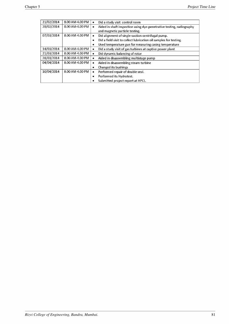
Chapter 5 Project Time Line
Rizvi College of Engineering, Bandra, Mumbai. 81

Chapter 6 Conclusion
Chapter 6
Conclusion
• The methods undertaken in this project are industry intensive. They help us obtain fairly ac-
curate inferences about the state of the system. It is possible that instrument of measurement
improve with time but not the method of performing analysis, diagnosis and repair, as they have
remained more or less the same over last 50 years.
• The methodology and technology is an exact science, but engineering isnt hence quality of work
depends upon the skill and experience of the performer of monitoring and maintenance operation.
• There are times when different tests produce varying inferences. Under those circumstances,
the diagnosis and repair of fault depends solely on the wit of the maintenance professionals.
• The field of monitoring is heavily sensor dependent hence there is much scope for automation
which would;
⋆ Remove the necessity of monitoring personnel going into difficult or hazardous locations for
monitoring the system.
⋆ Reduce the time for collecting data.
⋆ More conformity in quality of reading as the data transmission is automated.
⋆ Reduce the operating cost as automation would be a onetime investment.
• As automation gets cheaper it would be more widely used for monitoring purposes.
• The life of a rotary equipments depends upon the coating of internal surfaces and fluid pump.
The proper choice of such coats depends upon the expertise of maintenance professionals.
• Leakage of seals is very hazardous and polluting in petroleum industry hence they require criti-
cal attention. Again, improvements in sensor have improved the quality of inspection.
• Wear safety equipment at all times.
Rizvi College of Engineering, Bandra, Mumbai. 82

Chapter REFERENCES
References
Predictive Maintenance of Pumps Using Condition Monitoring by Raymond S. Beebe
Pump Handbook (4th Edition) - Karassik
Hydraulic Machines RK Rajput
Centrifugal pump vibrations: The cause by Steven J. Hrivnak
Forsthoffer’s Rotating Equipment Handbooks Vol-1 & Vol-2
Basic concept of operations, HPCL Mumbai refinery
Pump & Mechanical Seal , HPCL Mumbai refinery
Hand book on Pumps, Exchangers & Fired heaters, HPCL Mumbai Refinery
Rizvi College of Engineering, Bandra, Mumbai. 83

Chapter A Project Hosting
Appendix A
Project Hosting
The project is hosted at Google Code. The complete source code along with the manual to operate
the project and supplementary files are uploaded.
Project Link : https://www.academia.edu/6814752/PREDICTIVE MAINTENANCE & OVER-
HAULING OF ROTARY EQUIPMENTS IN HPCL REFINERY
QR CODE:
Rizvi College of Engineering, Bandra, Mumbai. 84