A procedure for the effective recalibration of liquid-in-glass ...
24
11^™^ United States Department of Commerce I Ih3 I National Institute of Standards and Technology NIST Special Publication 819 A Procedure for the Effective Recalihration of Liquid-in-Glass Thermometers Jacquelyn A, Wise NAT L INST. OF STAND S TECH R.I.C. A111D3 b33137 NIST PUBLICATiONS 100 .U57 #819 1991
-
Upload
khangminh22 -
Category
Documents
-
view
0 -
download
0
Transcript of A procedure for the effective recalibration of liquid-in-glass ...
11^™^ United States Department of Commerce
I Ih3 I National Institute of Standards and Technology
NIST Special Publication 819
A Procedure for the Effective
Recalihration of Liquid-in-Glass
Thermometers
Jacquelyn A, Wise
NAT L INST. OF STAND S TECH R.I.C.
A111D3 b33137
NIST
PUBLICATiONS
100
.U57
#819
1991

QUOD
NIST Special Publication 819
A Procedure for the Effective
Recalibration of Liquid-in-Glass
Thermometers
Jacquelyn A. Wise
Process Measurements Division
Technology Services
National Institute of Standards and Technology
Gaithersburg, MD 20899
August 1991
\
U.S. Department of Commerce
Robert A. Mosbacher, Secretary
National Institute of Standards and Technology
John W. Lyons, Director
National Institute of Standards
and Technology
Special Publication 819
Natl. Inst. Stand. Technol.
Spec. Publ. 819
17 pages (Aug. 1991)
CODEN: NSPUE2
U.S. Government Printing Office
Washington: 1991
For sale by the Superintendent
of Documents
U.S. Government Printing Office
Washington, DC 20402
CONTENTS
Page
1. Introduction 1
2. Recalibrating Liquid-in-Glass Thermometers - Method I 3
3. Recalibration of Liquid-in-Glass Thermometers - Method II 6
4. Preparing an Ice Bath 7
5. Reading Thermometers in the Ice Bath 9
6. Changing Liquid-in-Glass Thermometer Corrections
When the International Temperature Scale Changes 10
7. Conclusion 13
8. References 13
iii
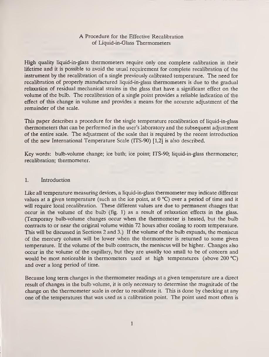
A Procedure for the Effective Recalibration
of Liquid-in-Glass Thermometers
High quality Hquid-in-glass thermometers require only one complete calibration in their
lifetime and it is possible to avoid the usual requirement for complete recalibration of the
instrument by the recalibration of a single previously calibrated temperature. The need for
recalibration of properly manufactured liquid-in-glass thermometers is due to the gradual
relaxation of residual mechanical strains in the glass that have a significant effect on the
volume of the bulb. The recalibration of a single point provides a reliable indication of the
effect of this change in volume and provides a means for the accurate adjustment of the
remainder of the scale.
This paper describes a procedure for the single temperature recalibration of liquid-in-glass
thermometers that can be performed in the user's laboratory and the subsequent adjustment
of the entire scale. The adjustment of the scale that is required by the recent introduction
of the new International Temperature Scale (ITS-90) [1,2] is also described.
Key words: bulb-volume change; ice bath; ice point; ITS-90; liquid-in-glass thermometer;
recalibration; thermometer.
1. Introduction
Like all temperature measuring devices, a liquid-in-glass thermometer may indicate different
values at a given temperature (such as the ice point, at 0 °C) over a period of time and it
will require local recalibration. These different values are due to permanent changes that
occur in the volume of the bulb (fig. 1) as a result of relaxation effects in the glass.
(Temporary bulb-volume changes occur when the thermometer is heated, but the bulb
contracts to or near the original volume within 72 hours after cooling to room temperature.
This will be discussed in Sections 2 and 3.) If the volume of the bulb expands, the meniscus
of the mercury column will be lower when the thermometer is returned to some given
temperature. If the volume of the bulb contracts, the meniscus will be higher. Changes also
occur in the volume of the capillary, but they are usually too small to be of concern and
would be most noticeable in thermometers used at high temperatures (above 200 °C)
and over a long period of time.
Because long term changes in the thermometer readings at a given temperature are a direct
result of changes in the bulb volume, it is only necessary to determine the magnitude of the
change on the thermometer scale in order to recalibrate it. This is done by checking at any
one of the temperatures that was used as a calibration point. The point used most often is
1
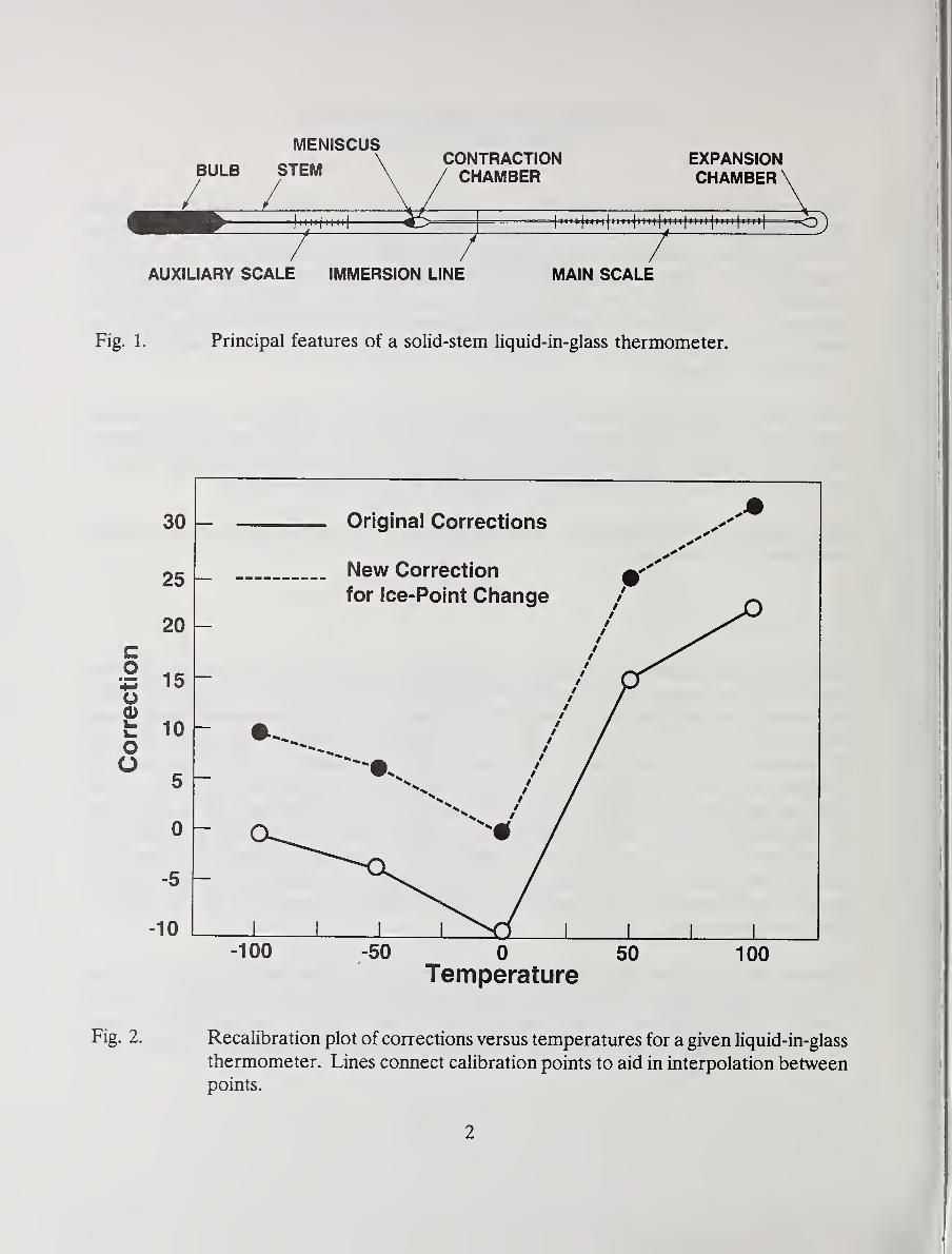
MENISCUS
BULB STEM
/ /N il III
CONTRACTIONCHAMBER
EXPANSIONCHAMBER
7| |||||| M ll| MM |l Ml|^^
AUXILIARY SCALE IMMERSION LINE MAIN SCALE
Fig. 1. Principal features of a solid-stem liquid-in-glass thermometer.
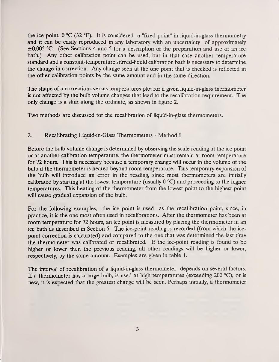
Fig. 2. Recalibration plot of corrections versus temperatures for a given liquid-in-glass
thermometer. Lines connect calibration points to aid in interpolation betweenpoints.
the ice point, 0 °C (32 °F). It is considered a "fixed point" in liquid-in-glass thermometry
and it can be easily reproduced in any laboratory with an uncertainty of approximately
±0.005 °C. (See Sections 4 and 5 for a description of the preparation and use of an ice
bath.) Any other calibration point can be used, but in that case another temperature
standard and a constant-temperature stirred-liquid calibration bath is necessary to determine
the change in correction. Any change seen at the one point that is checked is reflected in
the other calibration points by the same amount and in the same direction.
The shape of a corrections versus temperatures plot for a given liquid-in-glass thermometer
is not affected by the bulb volume changes that lead to the recalibration requirement. Theonly change is a shift along the ordinate, as shown in figure 2.
Two methods are discussed for the recalibration of liquid-in-glass thermometers.
2. Recalibrating Liquid-in-Glass Thermometers - Method I
Before the bulb-volume change is determined by observing the scale reading at the ice point
or at another calibration temperature, the thermometer must remain at room temperature
for 72 hours. This is necessary because a temporary change will occur in the volume of the
bulb if the thermometer is heated beyond room temperature. This temporary expansion of
the bulb will introduce an error in the reading, since most thermometers are initially
calibrated by starting at the lowest temperature (usually 0 °C) and proceeding to the higher
temperatures. This heating of the thermometer from the lowest point to the highest point
will cause gradual expansion of the bulb.
For the following examples, the ice point is used as the recalibration point, since, in
practice, it is the one most often used in recalibrations. After the thermometer has been at
room temperature for 72 hours, an ice point is measured by placing the thermometer in an
ice bath as described in Section 5. The ice-point reading is recorded (from which the ice-
point correction is calculated) and compared to the one that was determined the last time
the thermometer was calibrated or recalibrated. If the ice-point reading is found to be
higher or lower then the previous reading, all other readings will be higher or lower,
respectively, by the same amount. Examples are given in table 1.
The interval of recalibration of a liquid-in-glass thermometer depends on several factors.
If a thermometer has a large bulb, is used at high temperatures (exceeding 200 °C), or is
new, it is expected that the greatest change will be seen. Perhaps initially, a thermometer
3
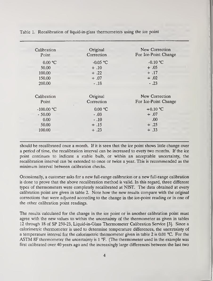
Table 1. Recalibration of liquid-in-glass thermometers using the ice point
Calibration
Point
0.00 °C
50.00
100.00
150.00
200.00
Original
Correction
-0.05 °C
-I- .10
-I- .22
+ .07
- .18
New Correction
For Ice-Point Change
-0.10 °C
-f- .05
+ .17
+ .02
- .23
Calibration Original New Correction
Point Correction For Ice-Point Change
-100.00 °C 0.00 °C +0.10 °C
- 50.00 - .03 + .07
0.00 - .10 .00
50.00 + .15 + .25
100.00 + .23 + .33
should be recalibrated once a month. If it is seen that the ice point shows little change over
a period of time, the recalibration interval can be increased to every two months. If the ice
point continues to indicate a stable bulb, or within an acceptable uncertainty, the
recalibration interval can be extended to once or twice a year. This is recommended as the
minimum interval between calibration checks.
Occasionally, a customer asks for a new full-range calibration or a new full-range calibration
is done to prove that the above recalibration method is valid. In this regard, three different
types of thermometers were completely recalibrated at NIST. The data obtained at every
calibration point are given in table 2. Note how the new results compare with the original
corrections that were adjusted according to the change in the ice-point reading or in one of
the other calibration point readings.
The results calculated for the change in the ice point or in another calibration point must
agree with the new values to within the uncertainty of the thermometer as given in tables
12 through 18 of SP 250-23, Liquid-in-Glass Thermometer Calibration Service [3], Since a
calorimetric thermometer is used to determine temperature differences, the uncertainty of
a temperature interval for the calorimetric thermometer given in table 2 is 0.01 °C. For the
ASTM 8F thermometer the uncertainty is 1 °F. (The thermometer used in the example was
first calibrated over 40 years ago and the increasingly large differences between the last two
4
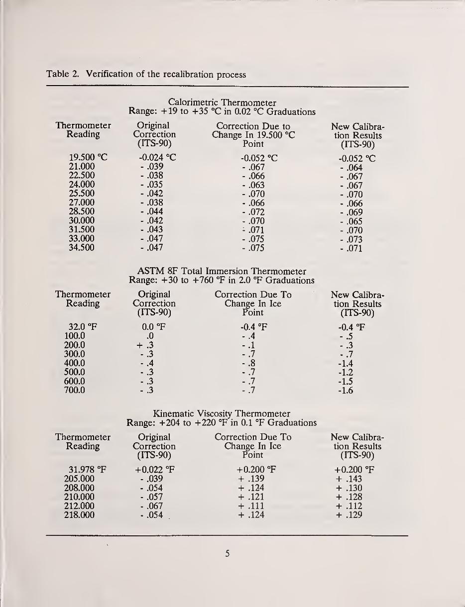
Table 2. Verification of the recalibration process
Calorimetric ThermometerRange: +19 to +35 "C in 0.02 °C Graduations
Thermometer Original Correction Due to New CalibraReading Correction Change In 19.500 °C tion Results
(ITS-90) Point (ITS-90)
19.500 ''C -0.024 °C -0.052 °C -0.052 °C21.000 - .039 - .067 - .06422.500 - .038 - .066 - .06724.000 - .035 - .063 - .067
- .042 - .070 - .U/u27.000 - .038 - .066 - .UOO28.500 - .044 - .072 - .06930.000 - .042 - .070 - .06531.500 - .043 - .071 - .07033.000 - .047 - .075 - .07334.500 - .047 - .075 - .071
ASTM 8F Total Immersion ThermometerRange: +30 to +760 °F in 2.0 T Graduations
Thermometer Original Correction Due To New Calibra-
Reading Correction Change In Ice tion Results(ITS-90) Point
32.0 T 0.0 °F -0.4 °F -0.4 °F.0 - .4 - .D
200.0 + .3 - .1 - ,J
300.0 -.3 - .7 - .7
400.0 - .4 - .8 -1.4
500.0 - .3 -.7 -1.2
600.0 - .3 -.7 -1.5
700.0 - .3 - .7 -1.6
Kinematic Viscosity ThermometerRange: +204 to +220 °F in 0.1 °F Graduations
Thermometer Original Correction Due To New Calibra-
Reading Correction Change In Ice tion Results(ITS-90) Point (ITS-90)
31.978 °F +0.022 T +0.200 T +0.200 T205.000 - .039 + .139 + .143
208.000 - .054 + .124 + .130
210.000 - .057 + .121 + .128
212.000 - .067 + .111 + .112
218.000 - .054 + .124 + .129
5
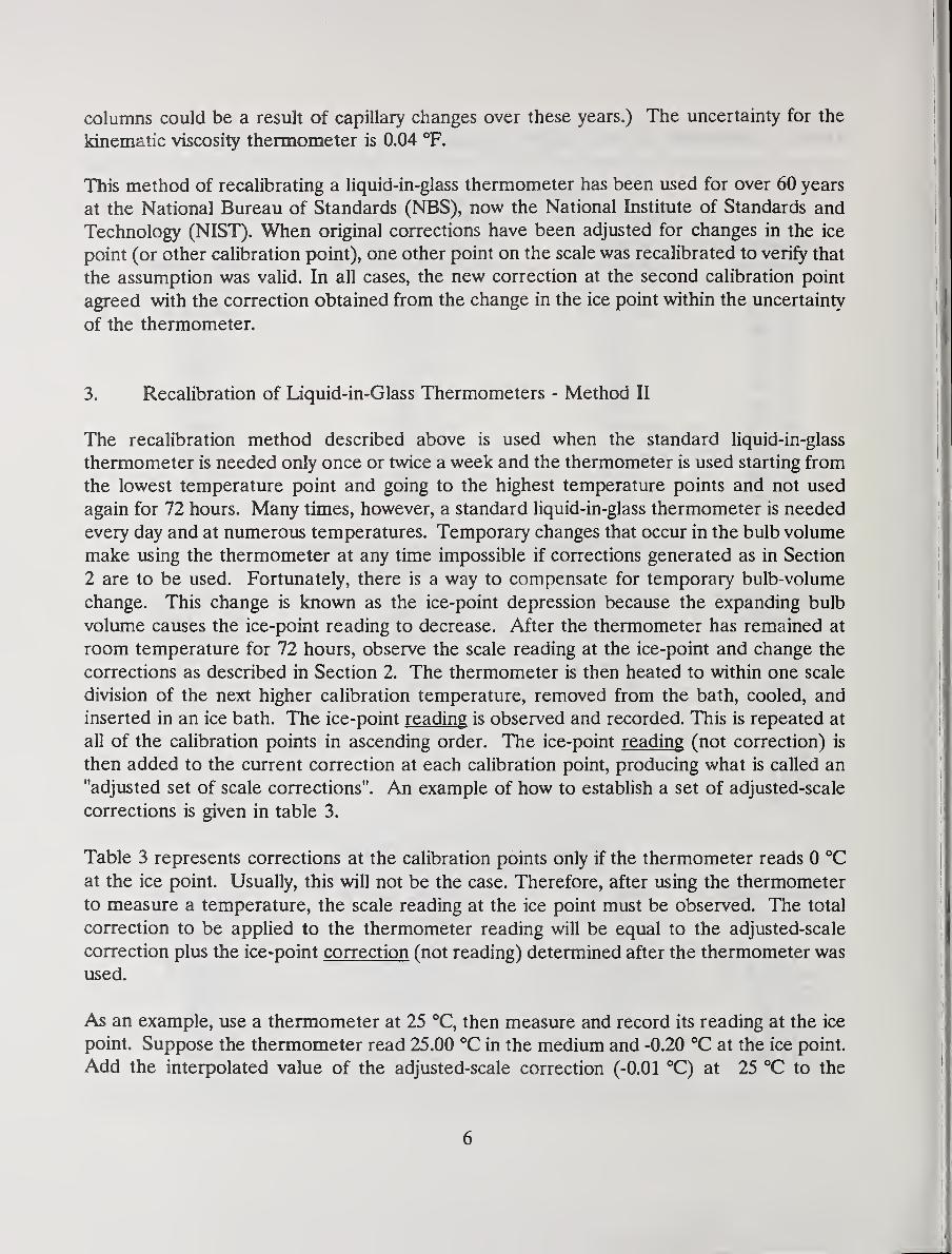
columns could be a result of capillary changes over these years.) The uncertainty for the
kinematic viscosity thermometer is 0.04 °F.
This method of recalibrating a liquid-in-glass thermometer has been used for over 60 years
at the National Bureau of Standards (NBS), now the National Institute of Standards and
Technology (NIST). When original corrections have been adjusted for changes in the ice
point (or other calibration point), one other point on the scale was recalibrated to verify that
the assumption was valid. In all cases, the new correction at the second calibration point
agreed with the correction obtained from the change in the ice point within the uncertainty
of the thermometer.
3. Recalibration of Liquid-in-Glass Thermometers - Method II
The recalibration method described above is used when the standard liquid-in-glass
thermometer is needed only once or twice a week and the thermometer is used starting from
the lowest temperature point and going to the highest temperature points and not used
again for 72 hours. Many times, however, a standard liquid-in-glass thermometer is needed
every day and at numerous temperatures. Temporary changes that occur in the bulb volume
make using the thermometer at any time impossible if corrections generated as in Section
2 are to be used. Fortunately, there is a way to compensate for temporary bulb-volume
change. This change is known as the ice-point depression because the expanding bulb
volume causes the ice-point reading to decrease. After the thermometer has remained at
room temperature for 72 hours, observe the scale reading at the ice-point and change the
corrections as described in Section 2. The thermometer is then heated to within one scale
division of the next higher calibration temperature, removed from the bath, cooled, and
inserted in an ice bath. The ice-point reading is observed and recorded. This is repeated at
all of the calibration points in ascending order. The ice-point reading (not correction) is
then added to the current correction at each calibration point, producing what is called an
"adjusted set of scale corrections". An example of how to establish a set of adjusted-scale
corrections is given in table 3.
Table 3 represents corrections at the calibration points only if the thermometer reads 0 °C
at the ice point. Usually, this will not be the case. Therefore, after using the thermometer
to measure a temperature, the scale reading at the ice point must be observed. The total
correction to be applied to the thermometer reading will be equal to the adjusted-scale
correction plus the ice-point correction (not reading) determined after the thermometer was
used.
As an example, use a thermometer at 25 °C, then measure and record its reading at the ice
point. Suppose the thermometer read 25.00 °C in the medium and -0.20 °C at the ice point.
Add the interpolated value of the adjusted-scale correction (-0.01 °C) at 25 °C to the
6
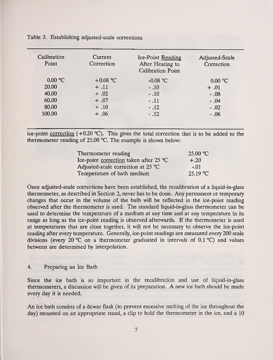
Table 3. Establishing adjusted-scale corrections
Calibration
Point
Current
Correction
Ice-Point Reading
After Heating to
Calibration Point
Adjusted-Scale
Correction
0.00 °C +0.08 °C -0.08 °C 0.00 °C20.00
40.00
60.00
80.00
100.00
+ .11
+ .02
+ .07
+ .10
+ .06
- .10
- .10
- .11
- .12
- .12
+ .01
- .08
- .04
- .02
- .06
ice-point correction (+0.20 °C). This gives the total correction that is to be added to the
thermometer reading of 25.00 °C. The example is shown below:
Once adjusted-scale corrections have been established, the recalibration of a liquid-in-glass
thermometer, as described in Section 2, never has to be done. Any permanent or temporary
changes that occur in the volume of the bulb will be reflected in the ice-point reading
observed after the thermometer is used. The standard liquid-in-glass thermometer can be
used to determine the temperature of a medium at any time and at any temperature in its
range as long as the ice-point reading is observed afterwards. If the thermometer is used
at temperatures that are close together, it will not be necessary to observe the ice-point
reading after every temperature. Generally, ice-point readings are measured every 200 scale
divisions (every 20 °C on a thermometer graduated in intervals of 0.1 °C) and values
between are determined by interpolation.
4. Preparing an Ice Bath
Since the ice bath is so important in the recalibration and use of liquid-in-glass
thermometers, a discussion will be given of its preparation. A new ice bath should be madeevery day it is needed.
An ice bath consists of a dewar flask (to prevent excessive melting of the ice throughout the
day) mounted on an appropriate stand, a clip to hold the thermometer in the ice, and a 10
Thermometer reading
Ice-point correction taken after 25 °C
Adjusted-scale correction at 25 °C
Temperature of bath medium
25.00 °C
+.20
-.01
25.19 °C
7
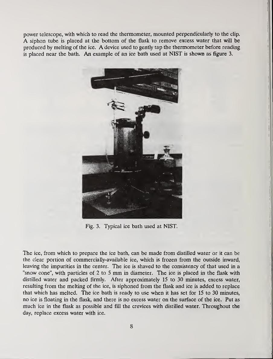
power telescope, with which to read the thermometer, mounted perpendicularly to the clip.
A siphon tube is placed at the bottom of the flask to remove excess water that will be
produced by melting of the ice. A device used to gently tap the thermometer before reading
is placed near the bath. An example of an ice bath used at NIST is shown as figure 3.
Fig. 3. Typical ice bath used at NIST.
The ice, from which to prepare the ice bath, can be made from distilled water or it can be
the clear portion of commercially-available ice, which is frozen from the outside inward,
leaving the impurities in the center. The ice is shaved to the consistency of that used in a
"snow cone", with particles of 2 to 5 mm in diameter. The ice is placed in the flask with
distilled water and packed firmly. After approximately 15 to 30 minutes, excess water,
resulting from the melting of the ice, is siphoned from the flask and ice is added to replace
that which has melted. The ice bath is ready to use when it has set for 15 to 30 minutes,
no ice is floating in the flask, and there is no excess water on the surface of the ice. Put as
much ice in the flask as possible and fill the crevices with distilled water. Throughout the
day, replace excess water with ice.
8
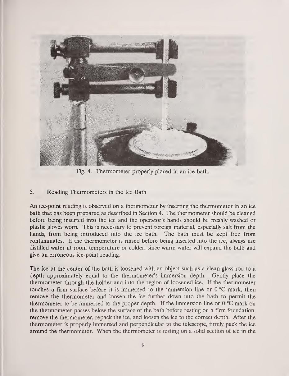
Fig. 4. Thermometer properly placed in an ice bath.
5. Reading Thermometers in the Ice Bath
An ice-point reading is observed on a thermometer by inserting the thermometer in an ice
bath that has been prepared as described in Section 4. The thermometer should be cleaned
before being inserted into the ice and the operator's hands should be freshly washed or
plastic gloves worn. This is necessary to prevent foreign material, especially salt from the
hands, from being introduced into the ice bath. The bath must be kept free from
contaminates. If the thermometer is rinsed before being inserted into the ice, always use
distilled water at room temperature or colder, since warm water will expand the bulb and
give an erroneous ice-point reading.
The ice at the center of the bath is loosened with an object such as a clean glass rod to a
depth approximately equal to the thermometer's immersion depth. Gently place the
thermometer through the holder and into the region of loosened ice. If the thermometer
touches a firm surface before it is immersed to the immersion line or 0 °C mark, then
remove the thermometer and loosen the ice further down into the bath to permit the
thermometer to be immersed to the proper depth. If the immersion line or 0 °C mark on
the thermometer passes below the surface of the bath before resting on a firm foundation,
remove the thermometer, repack the ice, and loosen the ice to the correct depth. After the
thermometer is properly immersed and perpendicular to the telescope, firmly pack the ice
around the thermometer. When the thermometer is resting on a solid section of ice in the
9
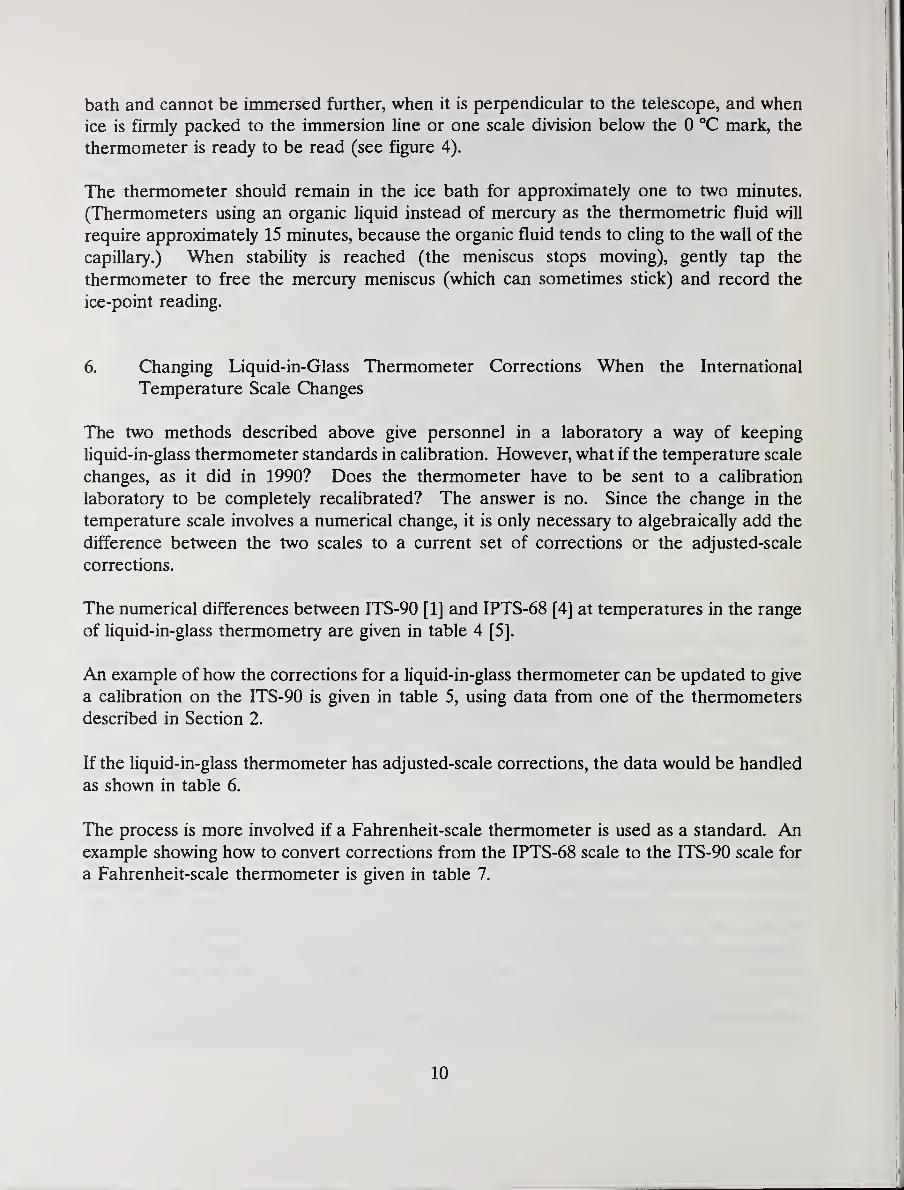
bath and cannot be immersed further, when it is perpendicular to the telescope, and when
ice is firmly packed to the immersion line or one scale division below the 0 "C mark, the
thermometer is ready to be read (see figure 4).
The thermometer should remain in the ice bath for approximately one to two minutes.
(Thermometers using an organic liquid instead of mercury as the thermometric fluid will
require approximately 15 minutes, because the organic fluid tends to cling to the wall of the
capillary.) When stability is reached (the meniscus stops moving), gently tap the
thermometer to free the mercury meniscus (which can sometimes stick) and record the
ice-point reading.
6. Changing Liquid-in-Glass Thermometer Corrections When the International
Temperature Scale Changes
The two methods described above give personnel in a laboratory a way of keeping
liquid-in-glass thermometer standards in calibration. However, what if the temperature scale
changes, as it did in 1990? Does the thermometer have to be sent to a calibration
laboratory to be completely recalibrated? The answer is no. Since the change in the
temperature scale involves a numerical change, it is only necessary to algebraically add the
difference between the two scales to a current set of corrections or the adjusted-scale
corrections.
The numerical differences between ITS-90 [1] and IPTS-68 [4] at temperatures in the range
of liquid-in-glass thermometry are given in table 4 [5].
An example of how the corrections for a liquid-in-glass thermometer can be updated to give
a calibration on the ITS-90 is given in table 5, using data from one of the thermometers
described in Section 2.
If the liquid-in-glass thermometer has adjusted-scale corrections, the data would be handled
as shown in table 6.
The process is more involved if a Fahrenheit-scale thermometer is used as a standard. Anexample showing how to convert corrections from the IPTS-68 scale to the ITS-90 scale for
a Fahrenheit-scale thermometer is given in table 7.
10
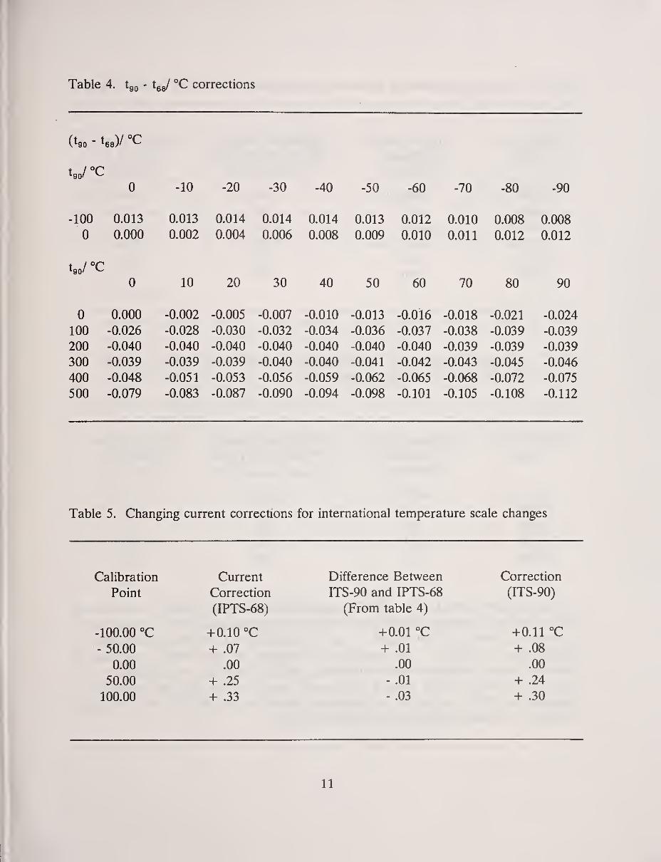
Table 4. tgo - tgg/ °C corrections
(tgo - tee)/ °C
0 -10 -?0 -30 -40 -SO -ow 70 80 QO
1 nn U.UlJ U.UiJ n 01/1 U.U14 U.UiZ U.UlU U.LKJo U.UUo
0 0.000 0.002 0.004 0.006 0.008 0.009 0.010 0.011 0.012 0.012
0 10 20 30 40 50 60 70 80 90
0 0.000 -0.002 -0.005 -0.007 -0.010 -0.013 -0.016 -0.018 -0.021 -0.024
100 -0.026 -0.028 -0.030 -0.032 -0.034 -0.036 -0.037 -0.038 -0.039 -0.039
200 -0.040 -0.040 -0.040 -0.040 -0.040 -0.040 -0.040 -0.039 -0.039 -0.039
300 -0.039 -0.039 -0.039 -0.040 -0.040 -0.041 -0.042 -0.043 -0.045 -0.046
400 -0.048 -0.051 -0.053 -0.056 -0.059 -0.062 -0.065 -0.068 -0.072 -0.075
500 -0.079 -0.083 -0.087 -0.090 -0.094 -0.098 -0.101 -0.105 -0.108 -0.112
Table 5. Changing current corrections for international temperature scale changes
Calibration
Point
-100.00 °C
- 50.00
0.00
50.00
100.00
Current
Correction
(IPTS-68)
+0.10 °C
+ .07
.00
+ .25
+ .33
Difference Between
ITS-90 and IPTS-68
(From table 4)
+0.01 °C
+ .01
.00
- .01
- .03
Correction
(ITS-90)
+0.11 °C
+ .08
.00
+ .24
+ .30
11
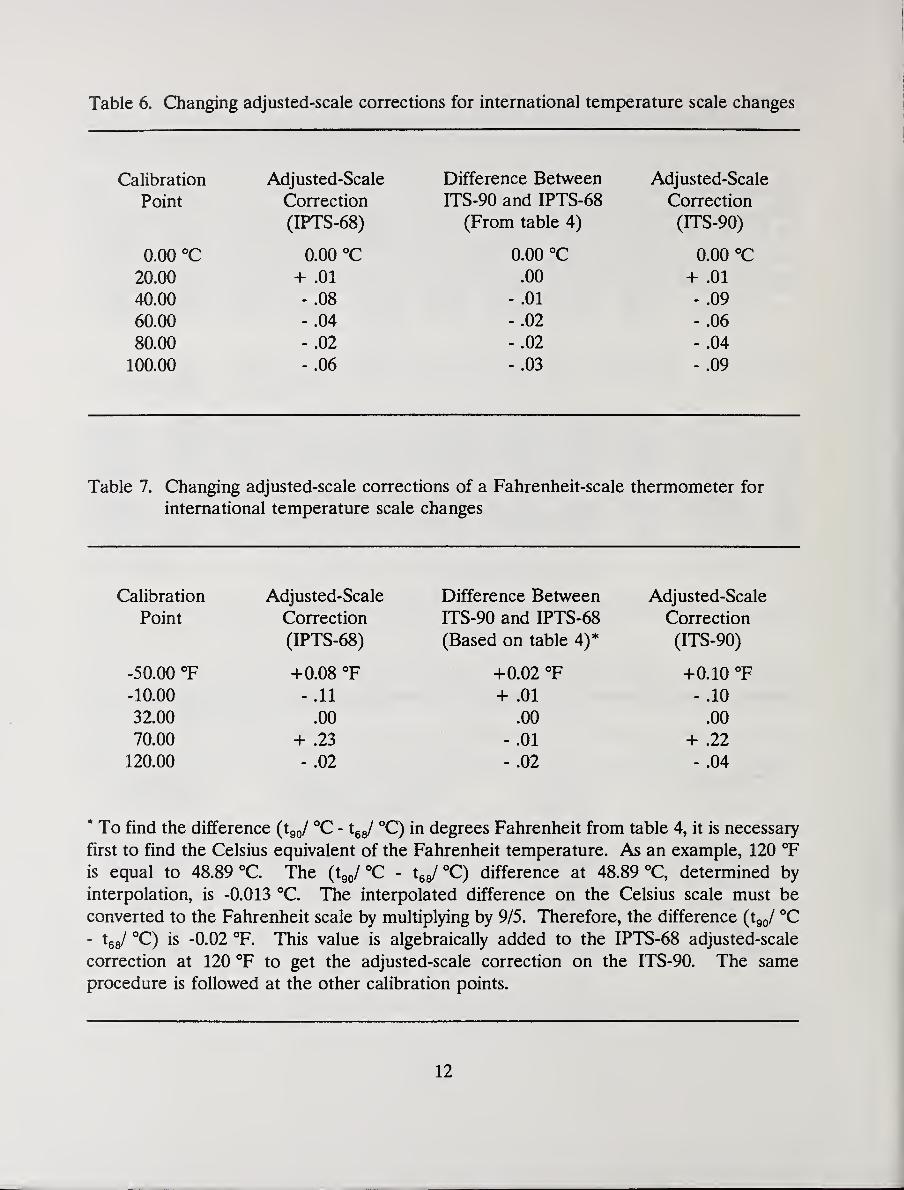
Table 6. Changing adjusted-scale corrections for international temperature scale changes
Calibration
Point
0.00 °C
20.00
40.00
60.00
80.00
100.00
Adjusted-Scale
Correction
(IPTS-68)
0.00 "C
+ .01
- .08
- .04
- .02
- .06
Difference Between
ITS-90 and IPTS-68
(From table 4)
0.00 °C
.00
- .01
- .02
- .02
- .03
Adjusted-Scale
Correction
(ITS-90)
0.00 °C
+ .01
- .09
- .06
- .04
- .09
Table 7. Changing adjusted-scale corrections of a Fahrenheit-scale thermometer for
international temperature scale changes
Calibration
Point
-50.00 °F
-10.00
32.00
70.00
120.00
Adjusted-Scale
Correction
(IPTS-68)
+0.0S °F
- .11
.00
+ .23
- .02
Difference Between
ITS-90 and IPTS-68
(Based on table 4)*
+0.02 °F
+ .01
.00
- .01
- .02
Adjusted-Scale
Correction
(ITS-90)
+0.10 °F
- .10
.00
+ .22
- .04
* To find the difference (tgj °C - X^J °C) in degrees Fahrenheit from table 4, it is necessary
first to find the Celsius equivalent of the Fahrenheit temperature. As an example, 120 °F
is equal to 48.89 °C. The {iJ^C - Xj°C) difference at 48.89 °C, determined by
interpolation, is -0.013 °C. The interpolated difference on the Celsius scale must be
converted to the Fahrenheit scale by multiplying by 9/5. Therefore, the difference {i^J °C- tgg/ °C) is -0,02 °F. This value is algebraically added to the IPTS-68 adjusted-scale
correction at 120 °F to get the adjusted-scale correction on the ITS-90. The same
procedure is followed at the other calibration points.
12
7. Conclusion
Method I, described in Section 2, for recalibrating liquid-in-glass thermometers has been
used for many years in laboratories throughout the world. It is intended that this paper be
a guide to lead laboratory personnel through the proper procedure for recalibrating
liquid-in-glass thermometers that are used as standards. Because the procedure is not
difficult and the method has been proven to be valid, the Liquid-in-Glass Thermometer
Calibration Laboratory at NIST will cease single temperature recalibration service for
customer's liquid-in-glass thermometers as of January 1, 1992. NIST will continue to
provide complete calibration of liquid-in-glass thermometers, however, and will also offer
a complete calibration of previously-calibrated thermometers when requested.
8. References
[1] Preston-Thomas, H., The International Temperature Scale of 1990 (ITS-90),
Metrologia 27, 3-10 (1990); Metrologia 27, 107 (1990).
[2] Mangum, B. W., Furukawa, G. T., Guidelines for Realizing the International
Temperature Scale of 1990 (ITS-90), Natl. Inst. Stand. Technol., TN 1265 (1990).
[3] Wise, J. A., Liquid-in-Glass Thermometer Calibration Service, Natl. Inst. Stand.
Technol., SP 250-23 (1988).
[4] The International Practical Temperature Scale of 1968, Metrologia 5, 35 (1969).
[5] Mangum, B. W., Report on The 17th Session of The Consultative Committee on
Thermometry, J. Res. Natl. Inst. Stand. Technol. 95, 69 (1990).
13
NIST-114A
(REV. 3-89)
U.S. DEPARTMENT OF COMMERCENATIONAL INSTITUTE OF STANDARDS AND TECHNOLOGY
BIBLIOGRAPHIC DATA SHEET
1. PUBUCATION OR REPORT NUMBER
NIST/SP-8192. PERFORMING ORGANIZATION REPORT NUMBER
3. PUBUCATION DATEAugust 1991
\A. TITLE AND SUBTITLE ^ p^^cedure for the EffectiveRecalibration of Liquid-ln-Glass Thermometers
5. AUTHOR(S)
Jacquelyn A. Wise
6. PERFORMING ORGANIZATION (IF JOINT OR OTHER THAN NIST, SEE INSTRUCTIONS)
U.S. DEPARTMENT OF COMMERCENATIONAL INSTITUTE OF STANDARDS AND TECHNOLOGYGAITHERSBURG, MD 20899
7. CONTRACT/GRANT NUMBER
8. TYPE OF REPORT AND PERIOD COVERED
Final
9. SPONSORING ORGANIZATION NAME AND COMPLETE ADDRESS (STREET, UTY, STATE, ZIP)
Same as Item #6
10. SUPPLEMENTARY NOTES
IDOCUMENT DESCRIBES A COMPUTER PROGRAM; SF-18S, FIPS SOFTWARE SUMMARY, IS ATTACHED.
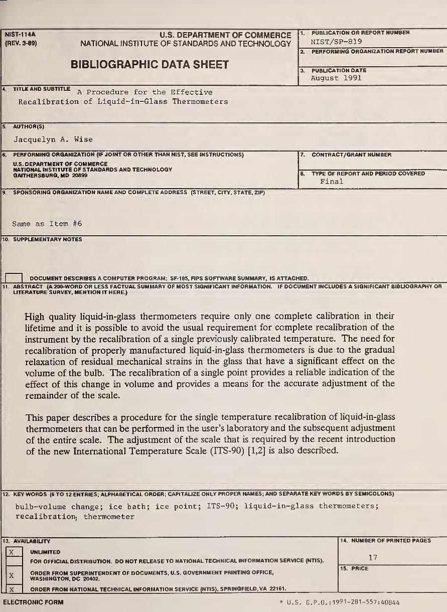
11. ABSTRACT (A 200-WORD OR LESS FACTUAL SUMMARY OF MOST SIGNIFICANT INFORMATION. IF DOCUMENT INCLUDES A SIGNIFICANT BIBUOGRAPHY ORUTERATURE SURVEY, MENTION IT HERE.)
High quality liquid-in-glass thermometers require only one complete calibration in their
lifetime and it is possible to avoid the usual requirement for complete recalibration of the
instrument by the recalibration of a single previously calibrated temperature. The need for
recalibration of properly manufactured liquid-in-glass thermometers is due to the gradual
relaxation of residual mechanical strains in the glass that have a significant effect on the
volume of the bulb. The recalibration of a single point provides a reliable indication of the
effect of this change in volume and provides a means for the accurate adjustment of the
remainder of the scale.
This paper describes a procedure for the single temperature recalibration of liquid-in-glass
thermometers that can be performed in the user's laboratory and the subsequent adjustment
of the entire scale. The adjustment of the scale that is required by the recent introduction
of the new International Temperature Scale (ITS-90) [1,2] is also described.
12. KEY WORDS (6 TO 12 ENTRIES; ALPHABETICAL ORDER; CAPITAUZE ONLY PROPER NAMES; AND SEPARATE KEY WORDS BY SEMICOLONS)
bulb-volume change; ice bath; ice point; lTS-90; liquid-in-glass thermometers;
recalibration. thermometer
13. AVAILABIUTY
UNUMITEO
FOR OFFICIAL DISTRIBUTION. DO NOT RELEASE TO NATIONAL TECHNICAL INFORMATION SERVICE (NTIS).
X
X
X
ORDER FROM SUPERINTENDENT OF DOCUMENTS, U.S. GOVERNMENT PRINTING OFFICE,WASHINGTON, DC 20402.
ORDER FROM NATIONAL TECHNICAL INFORMATION SERVICE (NTIS), SPRINGFIELD, VA 22161.
14. NUMBER OF PRINTED PAGES
17
15. PRICE
ELECTRONIC FORM * U.S. G.P.O. :1991-281-557:40U4A

i T kJ JL Technical Publications
Periodical
Journal of Research of the National Institute of Standards and Technology— Reports NISTresearch and development in those disciplines of the physical and engineering sciences in whichthe Institute is active. These include physics, chemistry, engineering, mathematics, and computersciences.
Papers cover a broad range of subjects, with major emphasis on measurement methodology andthe basic technology underlying standardization. Also included from time to time are surveyarticles on topics closely related to the Institute's technical and scientific programs. Issued six
times a year.
Nonperiodicals
Monographs — Major contributions to the technical literature on various subjects related to the
Institute's scientific and technical activities.
Handbooks — Recommended codes of engineering and industrial practice (including safety codes)developed in cooperation with interested industries, professional organizations, and regulatory
bodies.
Special Publications— Include proceedings of conferences sponsored by NIST, NIST annualreports, and other special publications appropriate to this grouping such as wall charts, pocketcards, and bibliographies.
Applied Mathematics Series— Mathematical tables, manuals, and studies of special interest to
physicists, engineers, chemists, biologists, mathematicians, computer programmers, and othersengaged in scientific and technical work.
National Standard Reference Data Series — Provides quantitative data on the physical and chemicalproperties of materials, compiled from the world's literature and critically evaluated. Developedunder a worldwide program coordinated by NIST under the authority of the National StandardData Act (Public Law 90-396). NOTE: The Journal of Physical and Chemical Reference Data(JPCRD) is published bi-monthly for NIST by the American Chemical Society (ACS) and the
American Institute of Physics (AIP). Subscriptions, reprints, and supplements are available fromACS, 1155 Sixteenth St., NW., Washington, DC 20056.
Building Science Series — Disseminates technical information developed at the Institute on building
materials, components, systems, and whole structures. The series presents research results, test
methods, and performance criteria related to the structural and environmental functions and the
durability and safety characteristics of building elements and systems.
Technical Notes— Studies or reports which are complete in themselves but restrictive in their
treatment of a subject. Analogous to monographs but not so comprehensive in scope or definitive
in treatment of the subject area. Often serve as a vehicle for final reports of work performed at
NIST under the sponsorship of other government agencies.
Voluntary Product Standards— Developed under procedures published by the Department of
Commerce in Part 10, Title 15, of the Code of Federal Regulations. The standards establish
nationally recognized requirements for products, and provide all concerned interests with a basis
for common understanding of the characteristics of the products. NIST administers this programas a supplement to the activities of the private sector standardizing organizations.
Consumer Information Series — Practical information, based on NIST research and experience,
covering areas of interest to the consumer. Easily understandable language and illustrations
provide useful background knowledge for shopping in today's technological marketplace.
Order the above NIST publications from: Superintendent of Documents, Government Printing Office,
Washington, DC 20402.
Order the following NIST publications— FIPS and NISTIRs—from the National Technical Information
Service, Springfield, VA 22161.
Federal Information Processing Standards Publications (FIPS PUB) — Publications in this series
collectively constitute the Federal Information Processing Standards Register. The Register serves
as the official source of information in the Federal Government regardmg standards issued byNIST pursuant to the Federal Property and Administrative Services Act of 1949 as amended.Public Law 89-306 (79 Stat. 1127), and as implemented by Executive Order 11717 (38 FR 12315,
dated May 11, 1973) and Part 6 of Title 15 CFR (Code of Federal Regulations).
NIST Interagency Reports (NISTIR)—A special series of interim or final reports on workperformed by NIST for outside sponsors (both government and non-government). In general,
mitial distribution is handled by the sponsor; public distribution is by the National Technical
Information Service, Springfield, VA 22161, in paper copy or microfiche form.
U.S. Department of CommerceNational Institute of Standards and Technology
Gaithersburg, MD 20899
Official Business
Penalty for Private Use $300