A preliminary study on the highway piezoelectric power supply ...
8
A preliminary study on the highway piezoelectric power supply system Hailu Yang a , Linbing Wang b,⇑ , Bin Zhou c , Ya Wei d , Qian Zhao e a National Center for Materials Service Safety, University of Science and Technology Beijing, Beijing 100083, China b Department of Civil and Environmental Engineering, Virginia Tech, USA c Yunnan Research Institute of Highway Science and Technology, Kunming 650000, China d Department of Civil Engineering, Tsinghua University, China e National Center for Materials Service Safety, University of Science and Technology Beijing, Beijing, China Received 9 September 2016; received in revised form 23 August 2017; accepted 25 August 2017 Abstract Pavement piezoelectric energy harvesting technique is to use a Piezoelectric Energy Harvester (PEH) to convert the mechanical energy of vehicles into electrical energy. A lot of research has been done on the technology of piezoelectric energy collection, but it is mainly focused on the theoretical model and the laboratory tests and lacks the on-site performance evaluation. In this paper, a stacked array type PEH is designed with protection package, which can improve the performance and the service life of the PEH. The demonstration project is also carried out to test the field performance. It is found that under the actual vehicle loading, the obtained piezoelectric energy can successfully light LED signs. Ó 2017 Production and hosting by Elsevier B.V. on behalf of Chinese Society of Pavement Engineering. This is an open access article under the CC BY-NC-ND license (http://creativecommons.org/licenses/by-nc-nd/4.0/). Keywords: PEH energy harvester; Energy collection; Sustainable development; Engineering application; Actual axle load 1. Introduction The transportation systems require a considerable amount of energy to maintain their regular operations. With the rapid development of society, the increasing energy consumption leads to the shortage of non- renewable energy resources. To solve this problem, many countries pay attention to the collection and use of renew- able energy. Pavement will bear millions of times of the axle loadings from traveling vehicles in its service life, resulting in deformation and vibration. Great mechanical energy is wasted during this process. It will be a break- through for energy conservation and emission reduction if the mechanical vibration energy is transformed into elec- tric energy. The piezoelectric energy harvesting technology has been studied for many years. Priya (2005) invented a pocket piezoelectric windmill which was attached to a rotating cam [1]. When the cam rotates, the motivated piezoelectric material will convert the mechanical energy into electric energy. Alexander et al. (2010) developed a system to col- lect vibration energy generated by pedestrians walking on the roads [2]. Yoshiyasu (2008) developed an energy collec- tion device which was embedded in the pavement [3]. It had been tested at subway entrance, shopping malls, etc. An Israel company INNOWATTECH (2010) announced that they had developed a pavement energy harvesting systems: Innowattech Piezo Electric Generator (IPEG), which is based on a piezoelectric transducer. According to reports, when traffic volume of vehicles is more than 500 in the http://dx.doi.org/10.1016/j.ijprt.2017.08.006 1996-6814/Ó 2017 Production and hosting by Elsevier B.V. on behalf of Chinese Society of Pavement Engineering. This is an open access article under the CC BY-NC-ND license (http://creativecommons.org/licenses/by-nc-nd/4.0/). ⇑ Corresponding author. E-mail addresses: [email protected] (H. Yang), [email protected] (L. Wang), [email protected] (B. Zhou), [email protected] (Y. Wei), [email protected] (Q. Zhao). Peer review under responsibility of Chinese Society of Pavement Engineering. www.elsevier.com/locate/IJPRT Available online at www.sciencedirect.com ScienceDirect International Journal of Pavement Research and Technology xxx (2017) xxx–xxx Please cite this article in press as: H. Yang et al., A preliminary study on the highway piezoelectric power supply system, Int. J. Pavement Res. Technol. (2017), http://dx.doi.org/10.1016/j.ijprt.2017.08.006
-
Upload
khangminh22 -
Category
Documents
-
view
2 -
download
0
Transcript of A preliminary study on the highway piezoelectric power supply ...

Available online at www.sciencedirect.com
www.elsevier.com/locate/IJPRT
ScienceDirect
International Journal of Pavement Research and Technology xxx (2017) xxx–xxx
A preliminary study on the highway piezoelectric power supply system
Hailu Yang a, Linbing Wang b,⇑, Bin Zhou c, Ya Wei d, Qian Zhao e
aNational Center for Materials Service Safety, University of Science and Technology Beijing, Beijing 100083, ChinabDepartment of Civil and Environmental Engineering, Virginia Tech, USA
cYunnan Research Institute of Highway Science and Technology, Kunming 650000, ChinadDepartment of Civil Engineering, Tsinghua University, China
eNational Center for Materials Service Safety, University of Science and Technology Beijing, Beijing, China
Received 9 September 2016; received in revised form 23 August 2017; accepted 25 August 2017
Abstract
Pavement piezoelectric energy harvesting technique is to use a Piezoelectric Energy Harvester (PEH) to convert the mechanical energyof vehicles into electrical energy. A lot of research has been done on the technology of piezoelectric energy collection, but it is mainlyfocused on the theoretical model and the laboratory tests and lacks the on-site performance evaluation. In this paper, a stacked arraytype PEH is designed with protection package, which can improve the performance and the service life of the PEH. The demonstrationproject is also carried out to test the field performance. It is found that under the actual vehicle loading, the obtained piezoelectric energycan successfully light LED signs.� 2017 Production and hosting by Elsevier B.V. on behalf of Chinese Society of Pavement Engineering. This is an open access article under the CCBY-NC-ND license (http://creativecommons.org/licenses/by-nc-nd/4.0/).
Keywords: PEH energy harvester; Energy collection; Sustainable development; Engineering application; Actual axle load
1. Introduction
The transportation systems require a considerableamount of energy to maintain their regular operations.With the rapid development of society, the increasingenergy consumption leads to the shortage of non-renewable energy resources. To solve this problem, manycountries pay attention to the collection and use of renew-able energy. Pavement will bear millions of times of theaxle loadings from traveling vehicles in its service life,resulting in deformation and vibration. Great mechanicalenergy is wasted during this process. It will be a break-
http://dx.doi.org/10.1016/j.ijprt.2017.08.006
1996-6814/� 2017 Production and hosting by Elsevier B.V. on behalf of Chin
This is an open access article under the CC BY-NC-ND license (http://creativec
⇑ Corresponding author.E-mail addresses: [email protected] (H. Yang), [email protected]
(L. Wang), [email protected] (B. Zhou), [email protected](Y. Wei), [email protected] (Q. Zhao).
Peer review under responsibility of Chinese Society of PavementEngineering.
Please cite this article in press as: H. Yang et al., A preliminary study on the h(2017), http://dx.doi.org/10.1016/j.ijprt.2017.08.006
through for energy conservation and emission reductionif the mechanical vibration energy is transformed into elec-tric energy.
The piezoelectric energy harvesting technology has beenstudied for many years. Priya (2005) invented a pocketpiezoelectric windmill which was attached to a rotatingcam [1]. When the cam rotates, the motivated piezoelectricmaterial will convert the mechanical energy into electricenergy. Alexander et al. (2010) developed a system to col-lect vibration energy generated by pedestrians walking onthe roads [2]. Yoshiyasu (2008) developed an energy collec-tion device which was embedded in the pavement [3]. It hadbeen tested at subway entrance, shopping malls, etc. AnIsrael company INNOWATTECH (2010) announced thatthey had developed a pavement energy harvesting systems:Innowattech Piezo Electric Generator (IPEG), which isbased on a piezoelectric transducer. According to reports,when traffic volume of vehicles is more than 500 in the
ese Society of Pavement Engineering.
ommons.org/licenses/by-nc-nd/4.0/).
ighway piezoelectric power supply system, Int. J. Pavement Res. Technol.
2 H. Yang et al. / International Journal of Pavement Research and Technology xxx (2017) xxx–xxx
single lane per hour, up to 250 kW of electrical energy canbe collected per kilometer per lane [4].
Guan et al. (2010) studied the cement-based piezoelec-tric materials for road power generation, where thecement-based piezoelectric composites are manufacturedby pre-embedding piezoelectric ceramics [5]. Zhao et al.(2011) designed the piezoelectric materials using the finiteelement analysis [6]. Xiong et al. (2012) show that the pave-ment deformation by vehicle processing and the vibrationcaused by moving vehicles on the road can be used forthe collection of electric energy, and the best power acqui-sition system is discussed in the study [7]. Xiang et al.(2013) considered the piezoelectric road model as the Ber-noulli–Euler beam model with pavement damping [8].Yuan et al. (2014) studied the use of piezoelectric transduc-ers in the collection of track vibration energy for railwaysafety driving and found that the piezoelectric energy har-vester could generate 30 mW power [9]. Zhang et al. (2014)studied the performance of a concrete-piezoelectric can-tilever beam transducer in a single vehicle using ANSYSsimulation [10].
In all, most of the research on the piezoelectric harvest-ing technology in pavement engineering is still in theexploratory stage. Although the previous studies have con-ducted preliminary theoretical analysis and laboratorytests, lack of engineering practice still limits the promotionof this new innovative green technology. In this paper, thestacked array piezoelectric energy harvester (PEH) isapplied to the actual road and its performance is tested.
2. Design of PEH for asphalt pavement
Since the PEH will be loaded millions or even billions oftimes during the service period, the PEH must have goodcompressive ability, fatigue resistance, waterproof andanti-corrosion performance. There have been manyresearches done in pavement materials’ area but few aboutPEHs [11,12]. In this study, the PEHs were prefabricatedand embedded in the pavement of a test site. Consideringthe contact area of tires, the PEH was designed to be30 cm wide and 30 cm long. PEHs in such dimension willhave better contact with the wheels of traveling vehicles.The thickness of the PEH is 8 cm, which is slightly thinnerthan the surface layer of the pavement from test site (9–10 cm). The PEH consists of 12 piezoelectric units, an inter-nal rectification circuit, and two power output cables.Other than a rectangular PEH, a circular PEH was alsofabricated with a diameter of 30 cm and a height of 8 cm,containing 12 piezoelectric units.
The PEH consists of four parts: the piezoelectric units,the packaging materials, the internal circuit boards andother sealing fastening components. The inner structureof the PEH is shown in Fig. 1.
The core component of the PEHs is piezoelectric mate-rial. This study adopted piezoelectric ceramics PZT-5H(produced by Baoding Hengsheng Acoustics ElectricApparatus Co., Ltd). For each unit, three PZT-5H slices
Please cite this article in press as: H. Yang et al., A preliminary study on the h(2017), http://dx.doi.org/10.1016/j.ijprt.2017.08.006
are stacked together and connected in parallel (c.f.Fig. 2). The dimension of the piezoelectric unit size isU20 � 23.2 mm.
Nylon (model: PA66 with 30% glass fiber) is selected tobe the protective packaging material of the piezoelectricenergy harvester. It has high strength, high load resistance,high toughness and high resistance to repeated shocks. Theprotection structure contains three layers: the upper, themiddle and the lower layer. The upper layer directly under-took the vehicle load and the lower supported with theground reaction force. The middle layer reserved the holesfor 12 piezoelectric units and desiccant positioning, andgrooves for wires and the internal circuit board (as shownin Fig. 3).
After connecting each of the piezoelectric units to thecircuit board, the power output will be rectified andextracted by the cable. The rectifier bridge is sealed withelectronic glue to prevent the short circuit caused by waterleakage. The sealing methods were as follows: applying sil-icone gasket between the upper and the lower encapsula-tion structure; putting the stainless steel gasket with adiameter of 40 between piezoelectric materials and wrap-ping it using protection package, to prevent stress concen-tration. Therefore, the piezoelectric energy harvester hasgood compression performance, fatigue resistance andwaterproof performance.
The LED demonstration board (Fig. 4) consists of fourChinese characters, meaning ‘‘piezoelectric demonstra-tion,” which adopted the high power LED yellow lampbead with condenser cover. The working voltage of LEDlamp bead is 3 V, and the working current is 10 mA. Eachcharacter on the board is organized with different numbersof lights’ series, respectively, 41 lights’ series, 50 lights’ ser-ies, 40 lights’ series, 50 lights’ series. There are a total of 181lamp beads, and the working voltage of each character was123 V, 150 V, 120 V, and 150 V respectively. Every charac-ter had two power supply lines, one for the positive and theother for the negative. There are eight wire lines in total,and all of the cables are connected to the output of thePEH through the connection chamber.
3. Demonstration project
The demonstration project of our piezoelectric powersupply system is located at K90 + 700 of Ma-Zhao High-way near Zhaotong City, Yunnan Province, where the totallength of trial pavement section is about 50 m. 20 fabri-cated PEHs are installed in real pavement, including 10rectangular and 10 circular ones. Ma-Zhao Highway is atwo-direction six-lane highway. PEHs are installed in themain lane near the emergency lane and along the wheelpath of the vehicles. The layout of the installation is illus-trated in Fig. 5. To reduce the damage from road construc-tion, the spacing is 2.5 m between two PEHs along the roadand the horizontal spacing is 1.875 m, which is consistentwith the axle structure of trailer trucks. A cable room isbuilt in the middle position of the demonstration road.
ighway piezoelectric power supply system, Int. J. Pavement Res. Technol.

Fig. 1. The inner structure of the PEH.
Fig. 2. The piezoelectric unit.
Fig. 3. Diagram of the protective middle layer.
Fig. 4. The LED board.
H. Yang et al. / International Journal of Pavement Research and Technology xxx (2017) xxx–xxx 3
The output wires of PEHs and the input wires of the LEDboard are connected in the cable room. The LED board islocated at the end of the test section, 30 m from the nearestPEH.
PEH installation process includes the following steps (asshown in Fig. 6): determining the position of each PEH,
Please cite this article in press as: H. Yang et al., A preliminary study on the h(2017), http://dx.doi.org/10.1016/j.ijprt.2017.08.006
cutting road surface, core-taking, dressing pit, installingthe PEH, laying the cable and filling the seam.
ighway piezoelectric power supply system, Int. J. Pavement Res. Technol.

Fig. 5. The schematic diagram of PEH laying.
Fig. 6. The installation process of the PEH.
4 H. Yang et al. / International Journal of Pavement Research and Technology xxx (2017) xxx–xxx
There are three coordinate positioning methods todetermine the positions of the PEHs. During the processof pavement construction, the positions of PEH have beendetermined, and the coordinates have been recorded. Thepositions are marked to make core-taking process easier.
The first step is to find the location according to therecorded coordinates. The second step is to cut the pave-
Please cite this article in press as: H. Yang et al., A preliminary study on the h(2017), http://dx.doi.org/10.1016/j.ijprt.2017.08.006
ment open using cutting machine. The pits for the PEHsand the slots for the wires are cut in this step. The third stepis to take out the asphalt concrete core. The bottom is flat-tened to make sure the distance between the bottom andthe road surface is equal to the thickness of the PEH inthe fourth step. The fifth step is to install the PEHs. Beforefilling the pit, it is necessary to make sure the pit is clean
ighway piezoelectric power supply system, Int. J. Pavement Res. Technol.

Fig. 7. The open circuit voltage curves of F2 and Y10 at different speeds.
H. Yang et al. / International Journal of Pavement Research and Technology xxx (2017) xxx–xxx 5
Please cite this article in press as: H. Yang et al., A preliminary study on the highway piezoelectric power supply system, Int. J. Pavement Res. Technol.(2017), http://dx.doi.org/10.1016/j.ijprt.2017.08.006
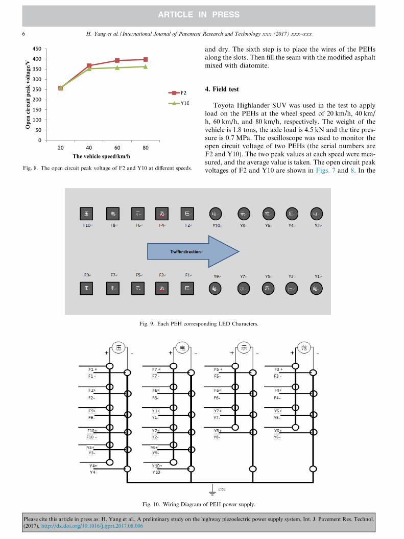
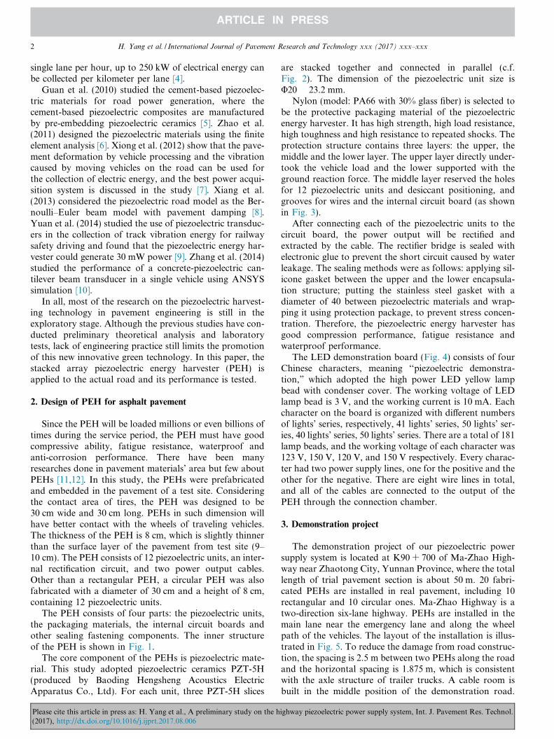
Fig. 8. The open circuit peak voltage of F2 and Y10 at different speeds.
Fig. 9. Each PEH correspo
Fig. 10. Wiring Diagram o
6 H. Yang et al. / International Journal of Pavement Research and Technology xxx (2017) xxx–xxx
Please cite this article in press as: H. Yang et al., A preliminary study on the h(2017), http://dx.doi.org/10.1016/j.ijprt.2017.08.006
and dry. The sixth step is to place the wires of the PEHsalong the slots. Then fill the seam with the modified asphaltmixed with diatomite.
4. Field test
Toyota Highlander SUV was used in the test to applyload on the PEHs at the wheel speed of 20 km/h, 40 km/h, 60 km/h, and 80 km/h, respectively. The weight of thevehicle is 1.8 tons, the axle load is 4.5 kN and the tire pres-sure is 0.7 MPa. The oscilloscope was used to monitor theopen circuit voltage of two PEHs (the serial numbers areF2 and Y10). The two peak values at each speed were mea-sured, and the average value is taken. The open circuit peakvoltages of F2 and Y10 are shown in Figs. 7 and 8. In the
nding LED Characters.
f PEH power supply.
ighway piezoelectric power supply system, Int. J. Pavement Res. Technol.

Fig. 11. SUV passed through the demonstration road.
Fig. 12. LED lights were lit by PEH devices.
H. Yang et al. / International Journal of Pavement Research and Technology xxx (2017) xxx–xxx 7
images of Fig. 7, the x-axis is time (unit: 1 s/div) and y-axisis the voltage (unit: 50 V/div).
As the speed of vehicle increases, the open circuit volt-age of embedded PEHs will rise, and more electric energyis produced. In addition, the influence of speed on the gen-erated power of PEH is greater at a low speed. In Fig. 8,the main reason for the difference between the two curvesis that the geometry of piezoelectric energy harvestersNo. F2 is different with the No. Y10. The cross sectionof F2 is square and Y10 is circular, so when the load passesfrom the pavement to the piezoelectric energy harvester,the loading process of the piezoelectric energy harvesteris different. The loading of circular piezoelectric energy har-vesters varies more gently and then the peak voltage of Y10is lower than F2.
The open circuit voltage ranges between 250 and 400 Vwhen the Toyota Highlander SUV passes the embeddedPEHs at the speed between 20 km/h and 80 km/h whichare good enough to be the power supply of the LED board.
Twenty PEH devices were embedded in demonstrationproject. The open circuit voltage of each PEH device meetsthe operating voltage of LED characters and supply powerfor one character. Methods of connecting wire betweenPEH device and LED Chinese character are shown inFigs. 9 and 10.
As shown in Fig. 11, when the vehicle passes through thedemonstration road, the LED Chinese character which isconnected to the corresponding PEH device will be lit
Please cite this article in press as: H. Yang et al., A preliminary study on the h(2017), http://dx.doi.org/10.1016/j.ijprt.2017.08.006
(see Fig. 12). The four LED characters are alternatelyflashing during the vehicles pass over the demonstrationroad. The time duration of LED bulbs being lit dependson the vehicle speed (less time indicates faster speed).Besides, LED brightness is affected by vehicle speed andwheel load. The LED will be lit and brighter with higherspeed and loading.
5. Conclusions
In this paper, a PEH is developed to convert themechanical energy wasted by traveling vehicles into electricenergy. The PEHs were installed in the pavement of a testsite, and the performance of the PEH was evaluated underthe real traffic loading. The PEH had an excellent powergenerating performance. The open circuit voltage gener-ated from the PEH under the actual road traffic conditionswas higher than 250 V. The output voltage was sensitive tothe vehicle speed and increases with the increase in speed.The electric energy produced by the PEH could be suppliedto the LED lamp, which could solve the problem of highcost of power supply system for the mountain highway.The energy collected by the PEH was derived from thepassed vehicles, and the electric energy was ultimately sup-plied to the road facilities, which was in accordance withthe concept of sustainable development.
Acknowledgement
The research performed in this paper is supported bytechnology project (NO. 2014318791080) from Ministryof communications and transportation of the People’sRepublic of China.
References
[1] S. Priya Modeling of electric energy harvesting using piezoelectricwindmill Appl. Phys. Lett. 8718 2005 184101-184101-3
[2] D. Alexander, M. Perille, Energy harvesting from a piezoelectricsidewalk[EB/OL], 2010, <http://www.seas.yale.edu/admin/uploads/46554544648ed06b348ec7.pdf> 2008.
[3] Yoshiyasu Takefuji, Known and unknown phenomena of nonlinearbehaviors in the power harvesting mat and the transverse wavespeaker, in: Proceedings of Inter-national Symposium on NonlinearTheory and Its Applications. Budapest, Republic of Hungary, 2008.
[4] INNOWATTECH, Innowattech’s solution-The innowat-tech piezo-electric generator (IPEGTM) [EB/OL], 2010, <http://www.innowat-tech.co.il/index.aspx>.
[5] Xinchun Guan, Yanchang Liu, Hui Li, Jinping Ou, Study onPreparation and properties of 1–3 cement based piezoelectric com-posites, J. Disaster Prevent. Mitigat. Eng. 30 (S1) (2010) 345–347.
[6] Zhao Hong-duo, Liang Ying-hui, Ling Jian-ming, Study on harvest-ing energy from pavement based on piezoelectric effects, J. ShanghaiJiaotong Univ 45 (S) (2011) 62.
[7] Haocheng Xiong, Linbing Wang, Dong Wang, Druta Cristian,Piezoelectric energy harvesting from traffic induced deformation ofpavements, Int. J. Pavement Res. Technol. 5 (5) (2012) 333.
[8] H.J. Xiang, J.J. Wang, Z.F. Shi, Z.W. Zhang, Theoretical analysis ofpiezoelectric energy harvesting from traffic induced deformation ofpavements, Smart Mater. Struct. 22 (9) (2013), 95024–95032(9).
ighway piezoelectric power supply system, Int. J. Pavement Res. Technol.

8 H. Yang et al. / International Journal of Pavement Research and Technology xxx (2017) xxx–xxx
[9] Yuan Tianchen, Yang Jian, Song Ruigang, Liu Xiaowei, Vibrationenergy harvesting system for railroad safety based on runningvehicles, Smart Mater. Struct. 23 (12) (2014).
[10] Y. Zhang, S.C.S. Cai, L. Deng, Piezoelectric-based energy harvestingin bridge systems, J. Intelligent Mater. Syst. Struct. 25 (12) (2013)1414–1428.
Please cite this article in press as: H. Yang et al., A preliminary study on the h(2017), http://dx.doi.org/10.1016/j.ijprt.2017.08.006
[11] Y. Hou, M. Guo, Z. Ge, L. Wang, W. Sun, Mixed-Mode I-IIcracking characterization of mortar using phase-field method, J. Eng.Mech. 143 (7) (2017) 04017033.
[12] Y. Hou, L. Wang, D.* Wang, P. Liu, M. Guo, J. Yu, Characteri-zation of bitumen micro-mechanical behaviors using AFM phasedynamics theory and MD simulation, Materials 10 (2) (2017) 208.
ighway piezoelectric power supply system, Int. J. Pavement Res. Technol.