Not All CBS Are Created Equally: COTS-Intensive Project Types
Upload
independentCategory
view
1download
0
Wireless Pers Commun (2012) 63:655–674DOI 10.1007/s11277-010-0157-7
A Practical Layer 3 Admission Control and AdaptiveScheduling (L3-ACAS) for COTS WLANs
W. L. Pang · David Chieng · Nurul Nadia Ahmad
Published online: 13 October 2010© Springer Science+Business Media, LLC. 2010
Abstract We propose a practical approach to provide QoS over the existing best-effortCommercial On The Shelf (COTS) IEEE802.11 WLANs using Layer 3 Admission Controland Adaptive Scheduling (L3-ACAS) scheme. This approach enables operators with exist-ing large-scale WLAN deployments to offer QoS control over their networks with minimaldisruption, capital expenditure (CAPEX) or infrastructure upgrade. Extensive simulationstudies show that with this scheme, the total goodput, flows throughput ratio, packets delayand jitter of the real-time applications such as VoIP and real-time video can be improvedsignificantly. We have also successfully implemented a testbed to evaluate our architectureusing the existing COTS hardware and the open source Linux components.
Keywords WLAN · Admission control · Scheduling · QoS architecture · DCF · EDCA
1 Introduction
WLAN technologies, particularly those based on IEEE802.11a/b/g standards [1–3] have beenenjoying enormous market adoption due to their ability to provide robust and yet relativelylow-cost wireless access service. BT Openzone wireless broadband service which mainlyrelies on IEEE802.11g [4] is now available at more than 5,000,000 homes, businesses andcity centers in the UK and Ireland [5]. Despite the success, large scale deployment of commer-cial services which require strict QoS control such as VoIP, live audio or video conferencing,etc., remains a challenge.
IEEE802.11, which primarily employs Distributed Coordinated Function (DCF) [2,3]uses Carrier Sense Multiple Access with Collision Avoidance (CSMA/CA) MAC protocol.This medium access control technique works perfectly well for best effort service but is
W. L. Pang (B) · N. N. AhmadMultimedia University, Cyberjaya, Malaysiae-mail: [email protected]
D. ChiengBT Malaysian Research Centre, BT Innovate and Design, Kuala Lumpur, Malaysia
123

656 W. L. Pang et al.
unable to support multimedia applications with strict QoS requirements [1–3]. A number ofsimple priority schemes can be easily implemented with minor modifications on DCF andthe outcomes seem encouraging [6–9]. However, such enhancements on the MAC protocolimply the need to replace the access points (APs) and hence incurring additional cost andtime.
The IEEE802.11e [10] introduces a new MAC called hybrid coordination function (HCF)which combines both contention based Enhanced Distributed Channel Access (EDCA) andhybrid coordination controlled channel access (HCCA) functions. HCF supports several pri-ority levels by introducing the concept of access category (AC). A station has up to four ACsto support eight different priorities, with each AC is being implemented as an independentqueue. The arriving packet is mapped in the MAC according to its priority level i.e. AC3,AC2, AC1 and AC0 for voice, video, best effort data and background traffics respectively.The EDCA uses a set of AC parameters with different contention windows (CWs) and arbi-tration inter-frame spaces (AIFSs) to differentiate the traffics. This function assigns a smallerCWmin, CWmax, or AIFS to higher priority AC to increase the channel access opportunity.Although IEEE802.11e is designed to provide QoS, it can only statically adjust the dura-tions of AIFS based on different priority levels in order to protect the real time traffic fromlower priority data traffic. Due to that, significant throughput degradation is experiencedwhen no real time traffic is present. Furthermore, when compared to IEEE802.11a, b and g,IEEE802.11e has not enjoyed a good market take-up to date.
Besides QoS control, a good admission control scheme is equally important, especially toprevent traffic load from becoming excessively high and subsequently paralyzes the network.In general, admission control is used to control the number of flows admitted to the network.Various admission control schemes for IEEE802.11 have been proposed. In [11] the schemepredicts the end-to-end residual bandwidths of the paths, and protects the existing flows fromQoS violations. The partitioning threshold admission control algorithm is proposed in [12]to control the flows admission.
Dynamically changing the QoS parameters based on the network condition is also a goodoption to provide QoS in WLAN. A dynamic queue length scheduling algorithm that dependson the operator requirements is proposed in [13] for downlink traffic. A similar approachis proposed in [14] to apply the dynamic priority re-allocation scheme in EDCA MAC andcontrolled the number of active stations over a traffic category. An adaptive two-level priori-ties scheme is proposed in [15] to control the throughput and delay of the real-time traffic byadjusting the minimum contention window. The mathematical model of the proposed schemeshown that it can provide service differentiation.
Although the above works promise QoS delivery over WLANs in one way or another,the design of our proposed architecture differs from the above with regards to the followingcriteria:
• It works on top of the existing DCF and EDCA MAC. This therefore enables best effortWLANs to be upgraded in a simple, non-disruptive and cost effective manner and alsoenhances the performance of the EDCA.
• It provides ease of control and management by means of having a centralized accesscontrol at the gateway/router side.
• In contrast to [6–15] which only offer simulation studies, L3-ACAS can be easily imple-mented using COTS hardware. This will be further discussed in the later section.
The remaining of this paper is organized as follows: The proposed architecture and algo-rithms are described in Sect. 2. Sections 3 and 4 discusses the simulation results and testbedimplementation respectively. Finally, a conclusion is drawn in Sect. 5.
123
A L3-ACAS for COTS WLANs 657
2 L3-ACAS
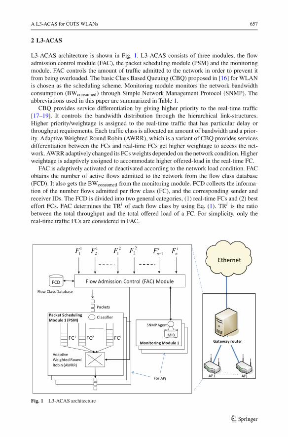
L3-ACAS architecture is shown in Fig. 1. L3-ACAS consists of three modules, the flowadmission control module (FAC), the packet scheduling module (PSM) and the monitoringmodule. FAC controls the amount of traffic admitted to the network in order to prevent itfrom being overloaded. The basic Class Based Queuing (CBQ) proposed in [16] for WLANis chosen as the scheduling scheme. Monitoring module monitors the network bandwidthconsumption (BWconsumed) through Simple Network Management Protocol (SNMP). Theabbreviations used in this paper are summarized in Table 1.
CBQ provides service differentiation by giving higher priority to the real-time traffic[17–19]. It controls the bandwidth distribution through the hierarchical link-structures.Higher priority/weightage is assigned to the real-time traffic that has particular delay orthroughput requirements. Each traffic class is allocated an amount of bandwidth and a prior-ity. Adaptive Weighted Round Robin (AWRR), which is a variant of CBQ provides servicesdifferentiation between the FCs and real-time FCs get higher weightage to access the net-work. AWRR adaptively changed its FCs weights depended on the network condition. Higherweightage is adaptively assigned to accommodate higher offered-load in the real-time FC.
FAC is adaptively activated or deactivated according to the network load condition. FACobtains the number of active flows admitted to the network from the flow class database(FCD). It also gets the BWconsumed from the monitoring module. FCD collects the informa-tion of the number flows admitted per flow class (FC), and the corresponding sender andreceiver IDs. The FCD is divided into two general categories, (1) real-time FCs and (2) besteffort FCs. FAC determines the TRi of each flow class by using Eq. (1). TRi is the ratiobetween the total throughput and the total offered load of a FC. For simplicity, only thereal-time traffic FCs are considered in FAC.
11F 1
2F 21F 2
2F inF 1−
inF
Fig. 1 L3-ACAS architecture
123

658 W. L. Pang et al.
Table 1 List of abbreviationsused in the algorithms
FC Flow class
BWconsumed Total bandwidth consumed
BW′consumed Total bandwidth consumed value measured
in previous measurement
BWthreshold Threshold value of the total bandwidthconsumption
BRi Bandwidth ratio of flow class i
BR′i Bandwidth ratio of flow class i calculated inprevious measurement
Rthreshold Threshold value of the bandwidth ratio
n Number of flows
Fi Flow class i
Fin Flow class iwith flow number n
tstep Time step
F_throughputin Throughput of the flow number n in flowclass i
F_offered_loadin Offered load of the flow number n in flow
class i
TRi Throughput ratio of flow class i
ACF Admission control flag signal
TRi =∑
F_throughputin∑F_offered_loadi
n
(1)
Algorithm 1 describes the operation of the adaptive admission control algorithm. It beginswith FAC comparing the BWconsumed value with the threshold value, BWthreshold. The Admis-sion Control Flag (ACF) is set to zero once the BWconsumed is less than BWthreshold and theadmission control is deactivated. ACF is set to 1 when BWconsumed > BWthreshold, the systemis potentially congested and the admission control is activated.
L3-ACAS accepts all the new flows when the ACF=0. L3-ACAS determines the TRi
in a loop program for all the real-time FCs in every tstep when ACF=1. If the ratioof BWconsumed/BW′
consumed is less than the threshold value, Rthreshold, it implies that thesystem total throughput is decreasing and the decreasing rate is more than the thresh-old ratio. When that occurs, L3-ACAS diverts the new Fi
n+1 flow to the best-effort FC.If BWconsumed/BW′
consumed > Rthreshold, the total throughput variation is in an accept-able range, either is slightly lower or higher than previously measured BW′
consumed value.L3-ACAS accepts the new Fi
n+1 flow once the TRi > Rthreshold, or else L3-ACAS divertsthe Fi
n and Fin+1 flows to the best-effort FC in order to reduce the number of active flows
and increases the TRi value. Higher TRi value means lower packets loss in that particularFC. If all the TRi values are below Rthreshold, L3-ACAS will stop assigning new IP addressto the new user and diverts all the new flows to the best-effort FCs. FAC updates the FCDaccordingly and repeats the measurement periodically in every tstep to guarantee the TRi ofeach FC is more than the threshold value, Rthreshold.
123

A L3-ACAS for COTS WLANs 659
Algorithm 1 L3-ACAS—Adaptive admission control algorithmACF=Admission control flagθ =number of real-time flows1: if BWconsumed < BWthresholdthen2: ACF=03: else ACF=14: end if5: for ACF==0 do6: accepts the new flow7: end for8: for ACF==1 do9: loop: i ={1, 2, 3,…., θ} {in every tstep} {10: if BWconsumed/BW′
consumed > Rthreshold then11: if TRi > Rthreshold then12: accepts the Fi
n+1flow13: else divert the Fi
n and Fin+1flows to the best-effort flow class
14: end if15: else divert the Fi
n+1flow to the best-effort flow class16: end if17: if all the TRi < Rthreshold then18: stop accepts new user and divert the new flow to best-effort FC19: else continue20: end if21: }22: BW′
consumed = BWconsumed
23: end for
Algorithm 2 L3-ACAS—Adaptive bandwidth rate configuration algorithmθ = number of real-time flows1: for every tstep do2: loop: i = {1, 2, 3, . . .., θ} {3: if TRi > Rthreshold then4: BRi = �F_offered_loadi/BWconsumed
5: else BRi = old BR′i6: end if7: Bandwidth share for best-effort flow class=1 − �BRi
8: }9: end for
FAC module accesses the monitoring module via the conventional Simple Network Man-agement Protocol (SNMP). More specifically, FAC interacts with SNMP agents in order toaccess the queue information stored in Management Information Base (MIB) database. Theinformation such as the total numbers of octets received and transmitted are obtained fromMIB is used to determine BWconsumed. FAC queries the data from MIB every tstep in order toget the updated parameters. PSM consists of two sub-modules, the packets queuing moduleand AWRR scheduler. In the packets queuing module, it configured multiple queues fromF1 to Fi to accommodate different types of FCs available in the network. Each flow class isoccupied a FC queue. F1 with the highest priority and followed by F2, F3 … and Fi . Thepackets from FAC are forwarded to a classifier. Classifier identifies the packet received and
123

660 W. L. Pang et al.
assigns the arriving packets to the appropriate FC queue. All the FC queues are scheduledby the AWRR scheduler before diverting the packets to the Wireless MAC. Real-time FCsare given higher weightage to access the WLAN compared to the best-effort FCs.
Algorithm 2 illustrates the operation of adaptive bandwidth rate configuration. This algo-rithm is used to determine the bandwidth share of each FC queue in PSM. Only the real-timeFCs are considered in this algorithm. It gathers the TRi of all the real-time FCs in every tstep.It also determines the bandwidth share of a FC queue through Eq. (2). If the TRi is more thanRthreshold, the bandwidth share of the Fi queue is set as BRi , or else the previous bandwidthshare, BR′i is used as the bandwidth share of Fi queue. The remaining bandwidth share isallocated to the best-effort FC queues in PSM.
BRi =∑
F_offered_loadi
BWconsumed(2)
One compelling point about L3-ACAS is that this scheme can be easily implementedusing real network testbed. The components used in this scheme are available in the freeopen source Linux environment and the algorithms can be written using bash scripts. Thedetail implementation of L3-ACAS is discussed in Sect. 4.
3 Simulation Analysis
We used Network Simulator tool (ns2) [20] to evaluate the proposed scheme. The wirelessstations are connected via half-duplex wireless radio based on IEEE802.11. The simulatoruses the standard two-ray ground propagation model and Omni-directional antenna. Thetransmission rate is set to 11 Mbps with RTS/CTS turned off. All the wireless stations areset to be stationary. The MAC parameters used in the simulations are shown in Table 2 andthe traffic used in the simulation is shown in Table 3. The simulations consists of three typesof FCs i.e. the F1 (VoIP), F2 (video) and best-effort F3 (FTP). Each VoIP session is bidirec-tional and produces 2 × 64 kbps CBR (constant bit rate) traffic with a fixed payload size of160 bytes, which corresponds to G.711 codec over a User Datagram Protocol (UDP). Videoflow is represented by the CBR traffic [8] with 640 kbps and payload size of 1,000 bytes. Allthe wireless stations download files from the wired stations using file transfer protocol (FTP)over TCP. All wireless stations are assumed to be within the 11 Mbps transmission range andthe simulation time is set to 100 s per iteration. For scalability analysis, a new station is addedto the system in every 5 s until the maximum of 20 stations is reached. The parameters andthreshold values used in L3-ACAS are listed in Table 4.
Table 2 MAC parameters of DCF and EDCA
Scheme DCF EDCA
AC – AC3 (Voice) AC2 (Video) AC1 (FTP)Slot 20µs 20µs
SIFS 10µs 10µs
DIFS 50µs –
AIFS – 30µs 30µs 50µs
CWmin 31 7 15 31
CWmax 1023 15 31 1023
123

A L3-ACAS for COTS WLANs 661
Table 3 Traffic configurations
Flow class (i) Traffic Transmission rate (kbps) Payload (bytes) Traffic Type
1 VoIP 2×64 160 CBR/UDP
2 Video 640 1, 000 CBR/UDP
3 FTP Always download 1, 000 FTP/TCP
Table 4 L3-ACAS parametersand thresholds
Parameter Value
BWthreshold 3 Mbps
Rthreshold 0.9
tstep 1 s
Fig. 2 Simulated network topology that consists of N wired and wireless stations
The following performance metrics are adopted in our study: (1) Total goodput(BWconsumed), (2) VoIP throughput ratio (TR1), (3) Average packet end-to-end delay ofVoIP flows, (4) Video throughput ratio (TR2), and (5) Average packet jitter of video flows.Delay is defined as the time interval from the time when a frame sends from the sender to thetime when the receiver receives it. In other words, delay including queuing delay, channelaccess delay, transmission delay and associated overhead. Jitter is the change in latency frompacket to packet that measures the variation in arrival rates between individual packets.
123

662 W. L. Pang et al.
Fig. 3 DCF flows throughput
Table 5 Number of flowscontrolled by L3-ACAS
Flow class (i) 1 2
L3-ACAS+DCF D1 4 4
D2 5 4
D3 3 5
D4 4 5
D5 5 5
L3-ACAS+EDCA E1 5 4
E2 6 4
E3 7 4
E4 6 3
E5 7 3
Figure 2 shows the simulated network topology. The scenario consists of 20 wired and20 wireless users (N=20) that are connected through a server and an access point (AP). L3-ACAS is implemented in the network router. The simulations are split in to two parts, withadaptive admission control algorithm (Algorithm 1) is disabled in the first part (Sects. 3.1and 3.2) and enabled in the second part (Sect. 3.3). The maximum number of flows of eachFC is statically preset in L3-ACAS to identify the effectiveness of L3-ACAS in variancetraffic conditions in Sects. 3.1 and 3.2. As shown in Figs. 3 and 4, in order to get sufficientbandwidth to support the real-time traffic, the maximum number of VoIP and Video are 4and 4 flows respectively in DCF. EDCA can supports 8 VoIP and 4 Video flows under thesame network topology. The maximum number of flows supported by DCF and EDCA areused as references to identify the suitable number of real-time flows that can be supported byL3-ACAS. The number of preset activated flows per FC used in the following simulationsis shown in Table 5. The preset values shown in Table 5 are generated by referring to themaximum number of the real-time flows as shown in Figs. 3 and 4. This is to identifythe optimal operation point of L3-ACAS. Finally the L3-ACAS architecture is evaluated inthe third simulation.
123

A L3-ACAS for COTS WLANs 663
Fig. 4 EDCA flows throughput
Fig. 5 Average system goodput
3.1 L3-ACAS over DCF
In this section the performance of the DCF is compared to the DCF+L3-ACAS. Five differentL3-ACAS configurations namely D1 to D5 (as in Table 5) are evaluated. As shown in Fig. 5,the maximum goodput of DCF is 3.5 Mbps and the value is decreased drastically once thereare more than six users admitted to the WLAN and the DCF goodput dropped to 1.5 Mbpsat the end of the simulation when the number of users increased to 20 users. This condi-tion is caused by high packets collision that occurred in the DCF. When the number of usersincreased in DCF, the offered load will also increase accordingly. This will increase the prob-ability of packets collision occurred. L3-ACAS controls the number of active real-time flowsin the real-time FCs and the probability of the real-time packets collision will be significantly
123

664 W. L. Pang et al.
Fig. 6 Average VoIP flows throughput ratio
Fig. 7 Average VoIP flow packets delay
reduced. The real-time traffic bandwidth is guaranteed and maintains a stable throughput inDCF with L3-ACAS. In general, L3-ACAS maintains a stable throughput when the numberof users increased. D3 goodput is the highest with the average value of more than 3.5 Mbpsthroughout the simulation, which due to D3 accommodated 5 video flows that contributedhigher traffic load. Nevertheless, the average goodput of all the L3-ACASs are much highercompared to the DCF system. At the end of the simulation, we achieve an improved good-put of 3.5 Mbps, which yields to a (3.5 − 1.5)/1.5 = 133% of the goodput improvementcompared to DCF.
The VoIP flows’ average throughput ratio and the average packet delay are shown inFigs. 6 and 7 respectively. The average VoIP throughput ratio of DCF is decreased drasticallyto less than 0.1 at the end of the simulation. This reflects that more than 90% of the VoIP
123

A L3-ACAS for COTS WLANs 665
Fig. 8 Average video flows throughput ratio
Fig. 9 Average video flow packets jitter
packets are dropped when more than 10 users are admitted to the network. All L3-ACASsprovide better average throughput ratio and D1 offers the best result followed by D3 withthe average ratios more than 0.9. The average packet delay of DCF increases drasticallywhen the number of users increases. All the L3-ACASs maintain a significantly low delay(120–140 ms) throughout the simulation and the average delay of D1 is the lowest amongother configurations.
The average throughput ratio and the average packet jitter of the video flows are shown inFigs. 8 and 9 respectively. The average video throughput ratio of DCF decreases drasticallyto less than 0.1 at the end of the simulation. All the L3-ACASs maintain a high averagethroughput ratio (>0.9). D1 is found to perform the best among all the other configurations.
123
666 W. L. Pang et al.
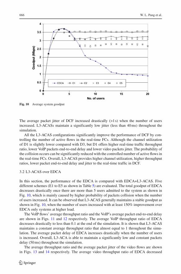
Fig. 10 Average system goodput
The average packet jitter of DCF increased drastically (>1 s) when the number of usersincreased. L3-ACASs maintain a significantly low jitter (less than 40 ms) throughout thesimulation.
All the L3-ACAS configurations significantly improve the performance of DCF by con-trolling the number of active flows in the real-time FCs. Although the channel utilizationof D1 is slightly lower compared with D3, but D1 offers higher real-time traffic throughputratio, lower VoIP packets end-to-end delay and lower video packets jitter. The probability ofthe collision occurs can be significantly reduced with the controlled number of active flows inthe real-time FCs. Overall, L3-ACAS provides higher channel utilization, higher throughputratios, lower packet end-to-end delay and jitter to the real-time traffic in DCF.
3.2 L3-ACAS over EDCA
In this section, the performance of the EDCA is compared with EDCA+L3-ACAS. Fivedifferent schemes (E1 to E5 as shown in Table 5) are evaluated. The total goodput of EDCAdecreases drastically once there are more than 5 users admitted to the system as shown inFig. 10, which is mainly caused by higher probability of packets collision when the numberof users increased. It can be observed that L3-ACAS generally maintains a stable goodput asshown in Fig. 10, when the number of users increased with at least 150% improvement overEDCA only systems at higher load.
The VoIP flows’ average throughput ratio and the VoIP’s average packet end-to-end delayare shown in Figs. 11 and 12 respectively. The average VoIP throughput ratio of EDCAdecreases drastically to less than 0.1 at the end of the simulation. It is shown that L3-ACASmaintains a constant average throughput ratio that almost equal to 1 throughout the simu-lation. The average packet delay of EDCA increases drastically when the number of usersis increased. Overall, L3-ACA is able to maintain a significantly low and constant packetsdelay (50 ms) throughout the simulation.
The average throughput ratio and the average packet jitter of the video flows are shownin Figs. 13 and 14 respectively. The average video throughput ratio of EDCA decreased
123

A L3-ACAS for COTS WLANs 667
Fig. 11 Average VoIP flows throughput ratio
Fig. 12 Average VoIP flow packets end-to-end delay
drastically to less than 0.1 at the end of the simulation. Overall, L3-ACAS maintains ahigh average throughput ratio. E1 and E3 are the highest (>0.98). The average packet jitterof EDCA increased drastically (>1 s) when the number of users increased. All L3-ACASconfigurations also maintain a significantly low and constant jitter (20 ms) throughout thesimulation.
L3-ACAS control the number of active real-time flows in the protected FCs, in order tomaintain a higher goodput, a higher real-time traffic throughput ratio, a lower packets end-to-end delay and jitter. L3-ACAS can significantly improve the performance of EDCA andE1 is the best configuration compared to the others as shown in the simulation results.
123

668 W. L. Pang et al.
Fig. 13 Average video flows throughput ratio
Fig. 14 Average video flow packets jitter
3.3 L3-ACAS with adaptive admission control algorithm
In the following simulation L3-ACAS operates without any preset condition under the sametraffic loads in order to evaluate the adaptive admission control algorithm. As shown inFig. 15, LD (L3-ACAS+DCF) admits 3 VoIP and 5 video flows, and LE (L3-ACAS+EDCA)admits 5 VoIP and 4 video flows in the same network topology. As shown in Fig. 16, LDand LE achieve significantly higher throughput (>3.5 Mbps) when compared with DCF andEDCA (>100% improvement in goodput).
It is observed that EDCA has a clear advantage in providing QoS when compared withDCF as it provides services differentiation to real-time traffic. With lower CWmin values asshown in Table 2 used in EDCA for real-time traffics, the real-time traffics get higher chances
123

A L3-ACAS for COTS WLANs 669
Fig. 15 Number of flows admitted to the network
Fig. 16 Average system goodput
to access the network compared to the best-effort traffics. The VoIP flows throughput ratioof DCF decreased drastically once there are more than 2 users admitted to the network asshown in Fig. 17. The same scenario is also observed in EDCA when there are more than 4users admitted to EDCA. In order to improve the throughput ratio of VoIP in DCF, L3-ACASdrops 2 active VoIP flows at 30 and 35 s as shown in Fig. 18. LD improves the throughputratio of VoIP from 0.75 at 25 s to 0.92 at 35 s. As shown in Fig. 17, the throughput ratio ofall the real-time traffic that protected by L3-ACAS is more than 0.9. When compared withDCF and EDCA systems without L3-ACAS, the throughput ratio of all the real-time trafficare less than 0.1 at the end of the simulation. This implies that almost 90% of the real-time
123

670 W. L. Pang et al.
Fig. 17 Average VoIP and video flows throughput ratio
Fig. 18 Average VoIP flow packets delay
packets are dropped in both systems. Both LD and LE successfully secure a stable and highergoodput.
As shown in Fig. 18, the end-to-end delay of VoIP packets are much lower in EDCAcompared to DCF that serves all the traffic equally, but when the number of active VoIPflows increases to more than 7 flows in EDCA, the VoIP packets delay of EDCA increaseddrastically. L3-ACAS successfully maintains a constant and lower VoIP packets delay in bothLD and LE systems. As shown in Fig. 19, the average video packets jitter are found to bearound 20–25 ms at the beginning of the simulation, but the video packets jitter of both DCFand EDCA increases drastically when the traffic load increases. Both DCF and EDCA failto provide the constant and low packets jitter for the video traffic but L3-ACAS successfully
123

A L3-ACAS for COTS WLANs 671
Fig. 19 Average video flow packets jitter
maintains a constant video packet jitter values throughout the simulation in both LD and LEsystems.
Overall, it can be concluded from the analysis above that L3-ACAS successfully increasesthe throughput ratio, and provides lower and constant average packets delay and jitter to thereal-time traffic. Although EDCA is able to provide a reasonable level of service differen-tiation, but without a good admission control implemented in EDCA, EDCA would fail toprovide QoS to the real-time traffic once the offered load increased. L3-ACAS successfullyprovides a better QoS with DCF compared to the normal EDCA system as shown in thesimulation results.
4 Experimental Results
In the testbed, L3-ACAS is implemented using a Linux Red Hat 9 operating system thatequipped with Intel Celeron 333 MHz processor, 256 MB SDRAM, and a 20 GB hard disk.COTS D-Link DWL-900+ AP and the D-Link DWL-520+ wireless adapters are used. Thetestbed adopts the same network topology as shown in Fig. 2. However, the testbed onlyconsists of 3 wired stations and 3 wireless stations (STA1–STA3). Due to small numberof stations, L3-ACAS is selectively programmed to provide service differentiation. SNMPconfiguration file “snmpd.conf” is configured to access the MIB of the AP, through the“DLINK-WLAN-MIB.mibs” configuration file. SNMP gets the MIB parameters from the APby using the “snmpget” command. The parameters collected are the “ifInOctets” and “ifOu-tOctets” values, with “ifInOctets”= total number of octets received on the AP and “ifOutOc-tets”= total number of octets transmitted on the AP. L3-ACAS gets the MIB parameters inevery tstep (5 s). The total throughput of the AP is calculated using Eq. (3). With ifInOctets’and ifOutOctets’ represented the MIB parameters collected in the previous cycle. Packetsanalyzer software, Windump is used to capture the throughput of the wireless users.
Total throughput = {(ifInOctets − ifInOctets′) +(ifOutOctets −ifOutOctets′)} × 8/5 (3)
123

672 W. L. Pang et al.
Table 6 BRi of each flow classFi BRi
F1 0.5
F2 0.3
F3 0.2
Fig. 20 Flows throughput of the experimental test
L3-ACAS shapes the wireless bandwidth to 2 Mbps. The bandwidth share of each flowclass is assigned by L3-ACAS, due to limited number of stations, the BRi is statically assignedand the values are shown in Table 6. L3-ACAS allocated 50% of it bandwidth to F1 (highestpriority), 30% to F2 (second priority) and 20% to F3 (lowest priority). All the traffic fromSTA1 is diverted to F1 queue, STA2 to F2 and STA3 to F3. All STAs receives video streamingand downloaded data through FTP from the wired stations. VideoLAN version 8.2 is usedfor the video streaming. The video streaming with total transmission rate of 288 kbps thatconsists of 256 kbps video and 32 kbps audio traffic are streamed to all the wireless users.Since the total throughput is shaped to 2 Mbps and is much lower than BWthreshold, all theflows are accepted by L3-ACAS.
The resulting flows’ throughput is shown in Fig. 20. The maximum throughput of the sys-tem is 2 Mbps, and all the stations obtained the allocated bandwidth share from L3-ACAS.STA1 get 50%, STA2 30% and the remaining 20% to STA3. The STAs receive the allocatedbandwidth share although the number of STAs in the system is changed as shown in Fig. 20.The experimental result shows that the L3-ACAS is able to provide service differentiationand bandwidth guarantee to the wireless users.
5 Conclusion
A Layer 3 Admission Control and Adaptive Scheduling scheme for provisioning QoS for thereal-time applications over COTS IEEE802.11 WLANs is proposed in this paper. L3-ACASoffers a natural improvement over the existing DCF and EDCA. Extensive simulation studiesshow that the L3-ACAS effectively enhances the performance of the real-time applications,with the average throughput ratio >0.9, average VoIP end-to-end packets delay=120 mswith L3_ACAS + DCF and 55 ms with L3-ACAS + EDCA, and the average video packets
123
A L3-ACAS for COTS WLANs 673
jitter=25 ms. The best operation points of L3-ACAS over DCF and EDCA have also beenidentified in this paper. From practical viewpoint, L3-ACAS is cost effective as it can beeasily implemented using COTS hardware that is powered by free Linux OS. Therefore fornetwork operators with large-scale deployments, L3-ACAS offers an attractive means forQoS support with minimal disruptions, CAPEX expenditures or infrastructure upgrade.
References
1. IEEE 802.11a W. G. (1999). Part 11: Wireless LAN Medium Access Control (MAC) and PhysicalLayer (PHY) specification: High-speed Physical Layer in the 5 GHz Band, Sep. 1999.
2. IEEE 802.11b W. G. (1999). Part 11: Wireless LAN Medium Access Control (MAC) and PhysicalLayer (PHY) specification: High-speed Physical Layer Extension in the 2.4 GHz Band, IEEE, Sep.1999.
3. IEEE Std 802.11g/D1.1 (2001). Part11: Wireless LAN Medium Access Control (MAC) and PhysicalLayer (PHY) specifications: Further Higher-Speed Physical Layer Extension in the 2.4 GHz Band.
4. Wi-Fi technical details. http://www.btopenzone.com/help/technical-details/index.jsp.5. BT lights up half a million wifi hotspots (2009). Telecoms.com, August 20, http://www.telecoms.
com/13962/bt-lights-up-half-a-million-wifi-hotspots6. Yilmaz, O., & Chen, I. R. (2009). Elastic threshold-based admission control for QoS satisfaction
with reward optimization for servicing multiple priority classes in wireless networks. InformationProcessing Letters, 109(15), 868–875.
7. Cetinkaya, C. (2009). Service differentiation mechanisms for WLANs. Ad Hoc Networks, 8(1), 46–62.8. Xiao, Y., Li, F.H., & Choi, S. (2009). Two-level protection and guarantee for multimedia traffic in
IEEE 802.11e distributed WLANs. Wireless Networks, 15(2), 141–161. (1022–0038).9. Kim, S., Cho, Y. J., Kim Y. K. (2009). Admission control scheme based on priority access for wireless
LANs. Computer Networks.10. IEEE Std 802.11eTM-2005 (2005) Part 11: Wireless LAN Medium Access Control (MAC) and phys-
ical layer (PHY) specifications: Medium Access Control (MAC) Quality of Service Enhancements,November 2005.
11. Liu, T. H., Liao, W. J., & Lee, J. F. (2009). Distributed contention-aware call admission controlfor IEEE 802.11 multi-radio multi-rate multi-channel wireless mesh networks. Mobile Networks andApplications, 14(2), 134–142. (1572–8153).
12. Yilmaz, O., & Chen, I.R. (2009). Utilizing call admission control for pricing optimization of multipleservice classes in wireless cellular networks. Computer Communications, 32(2), 317–323.
13. Zorba, N. & Verikoukis, C. (2010). A QoS-based dynamic queue length scheduling algorithm inmultiantenna heterogeneous systems. EURASIP Journal on Wireless Communications and Networking,2010.
14. Ming, L., Hua, Z., & Prabhakaran, B. (2010). Dynamic priority re-allocation scheme for quality ofservice in IEEE 802.11e wireless networks. Wireless Networks, 16, 759–774.
15. Ahmed, M., Fadeel, G. A., Ibrahim, I. I. (2010). Differentiation between different traffic cate-gories using multi-level of priority in DCF-WLAN. Sixth Advanced International Conference onTelecommunications, pp. 262–267, 9–15 May 2010.
16. Pang, W. L., Chieng, D., & Nadia, N. (2009). Enhanced layer 3 service differentiation for WLAN. WSEASTransactions on Systems, 8(5), 649–658.
17. Floyd, S., & Jacobson, V. (1995). Link-sharing and resource management models for packet networks.IEEE/ACM Transactions on Networking, 3, 365–386.
18. Floyd, S. (1995). Notes of class-based queuing: setting parameters, informal notes, September 1995.19. Floyd, S. (1995). Notes on CBQ and Guaranteed Service. Draft document, July 1995.20. The Network Simulator – ns2, http://www.isi.edu/nsnam/ns.
123

674 W. L. Pang et al.
Author Biographies
W. L. Pang is a lecturer in the Faculty of Engineering at MultimediaUniversity, Malaysia. His research interests include wireless networks,VLSI analog and digital designs. Pang received his M.Sc. in electronicfrom University Putra Malaysia.
David Chieng joined BT Malaysian Research Centre as a technicalgroup leader in broadband wireless research group in 2006. While inBT he led a work package in EU ICT Seventh Framework ProgramCarrier Grade Wireless Mesh Network (CARMEN) project (http://www.ict-carmen.eu/). Prior to BT, he was the principal researcher inproject BONDS (Brokering Open Network Differentiated Services),a collaborative project between Queen’s University of Belfast, UlsterUniversity and Fujitsu Telecommunications Europe Ltd. From 2002–2003, he worked as a product specialist (VoIP solutions) for a regionaltelecommunication software and system integration company. From2003–2006, he was a lecturer, then senior lecturer in Faculty of Engi-neering, Multimedia University, Malaysia and was leading two jointresearch projects with Panasonic R&D Centre, Malaysia, in the areasof Computer Telephony Integration and Ubiquitous Computing. Davidreceived his M.Sc. and Ph.D. from the School of Electrical and Elec-tronic Engineering, Queen’s University of Belfast, Northern Ireland,
U.K., in 1998 and 2002 respectively. He has authored and co-authored >30 publications in international jour-nals, conferences and book chapters. He has also filed 7 patents in the area of wireless and computing sys-tems. He serves as a regular reviewer for IET proceeding, Elsevier Science Computer Networks, and TPCand reviewer for major international conferences such as ICC, VTC, WCNC, etc.
Nurul Nadia Ahmad received B.E. degree in Electronic and Com-munications from University of Bristol, U.K., in 1999, and the Ph.D.degree in Electronics and Electrical Engineering (Wireless Communi-cations Group) from University of Southampton, U.K., in 2005. Since1999, she has been with Multimedia University, Malaysia. Her researchinterests include wireless communications and image processing.
123
Copyright © 2022 FDOKUMEN