A Power-Efficient MAC Protocol with Two-Level Transmit Power Control in Ad Hoc Network Using...
10
A Power-Efficient MAC Protocol with Two-Level Transmit Power Control in Ad Hoc Network Using Directional Antenna Dola Saha 1 , Siuli Roy 1 , Somprakash Bandyopadhyay 1 , Tetsuro Ueda 2 , Shinsuke Tanaka 2 1 Indian Institute of Management Calcutta Diamond Harbour Road, Joka Calcutta 700104, India {dola, siuli, somprakash}@iimcal.ac.in 2 ATR Adaptive Communications Research Laboratories 2-2-2 Hikaridai, Keihanna Science City, Kyoto 619-0288, Japan {teueda, shinsuke}@atr.co.jp Abstract. The use of directional antenna in wireless ad hoc networks largely reduces radio interference, thereby improving the utilization of wireless me- dium and consequently the network throughput, as compared to omni- directional antenna, where nodes in the vicinity of communication are kept si- lent. In this context, researchers usually assume that the gain of directional an- tennas is equal to the gain of corresponding omni-directional antenna. How- ever, for a given amount of input power, the range R with directional antenna will be much larger than that using omni-directional antenna. In this paper, we propose a two-level transmit power control mechanism in order to approxi- mately equalize the transmission range R of an antenna operating at omni- directional and directional mode. This will not only improve medium utiliza- tion but also help to conserve the power of the transmitting node during direc- tional transmission. The performance evaluation on QualNet network simulator clearly indicates the efficiency of our protocol. 1 Introduction Usually, in ad hoc networks, all nodes are equipped with omni-directional antenna. However, ad hoc networks with omni-directional antenna uses RTS/CTS based floor reservation scheme that wastes a large portion of the network capacity by reserving the wireless media over a large area. Consequently, lot of nodes in the neighborhood of transmitter and receiver has to sit idle, waiting for the data communication between transmitter and receiver to finish. To alleviate this problem, researchers have pro- posed to use directional (fixed or adaptive) antennas that direct the transmitting and receiving beams toward the receiver and transmitter node only. This would largely reduce radio interference, thereby improving the utilization of wireless medium and consequently the network throughput [1-6]. As shown in Fig. 1, while node n is communicating with node m using omni-directional antenna, node p and r have to sit
-
Upload
independent -
Category
Documents
-
view
2 -
download
0
Transcript of A Power-Efficient MAC Protocol with Two-Level Transmit Power Control in Ad Hoc Network Using...
A Power-Efficient MAC Protocol with Two-LevelTransmit Power Control in Ad Hoc Network Using
Directional Antenna
Dola Saha1, Siuli Roy1, Somprakash Bandyopadhyay1,Tetsuro Ueda2, Shinsuke Tanaka2
1 Indian Institute of Management CalcuttaDiamond Harbour Road, Joka Calcutta 700104, India
{dola, siuli, somprakash}@iimcal.ac.in2 ATR Adaptive Communications Research Laboratories
2-2-2 Hikaridai, Keihanna Science City, Kyoto 619-0288, Japan{teueda, shinsuke}@atr.co.jp
Abstract. The use of directional antenna in wireless ad hoc networks largelyreduces radio interference, thereby improving the utilization of wireless me-dium and consequently the network throughput, as compared to omni-directional antenna, where nodes in the vicinity of communication are kept si-lent. In this context, researchers usually assume that the gain of directional an-tennas is equal to the gain of corresponding omni-directional antenna. How-ever, for a given amount of input power, the range R with directional antennawill be much larger than that using omni-directional antenna. In this paper, wepropose a two-level transmit power control mechanism in order to approxi-mately equalize the transmission range R of an antenna operating at omni-directional and directional mode. This will not only improve medium utiliza-tion but also help to conserve the power of the transmitting node during direc-tional transmission. The performance evaluation on QualNet network simulatorclearly indicates the efficiency of our protocol.
1 Introduction
Usually, in ad hoc networks, all nodes are equipped with omni-directional antenna.However, ad hoc networks with omni-directional antenna uses RTS/CTS based floorreservation scheme that wastes a large portion of the network capacity by reservingthe wireless media over a large area. Consequently, lot of nodes in the neighborhoodof transmitter and receiver has to sit idle, waiting for the data communication betweentransmitter and receiver to finish. To alleviate this problem, researchers have pro-posed to use directional (fixed or adaptive) antennas that direct the transmitting andreceiving beams toward the receiver and transmitter node only. This would largelyreduce radio interference, thereby improving the utilization of wireless medium andconsequently the network throughput [1-6]. As shown in Fig. 1, while node n iscommunicating with node m using omni-directional antenna, node p and r have to sit
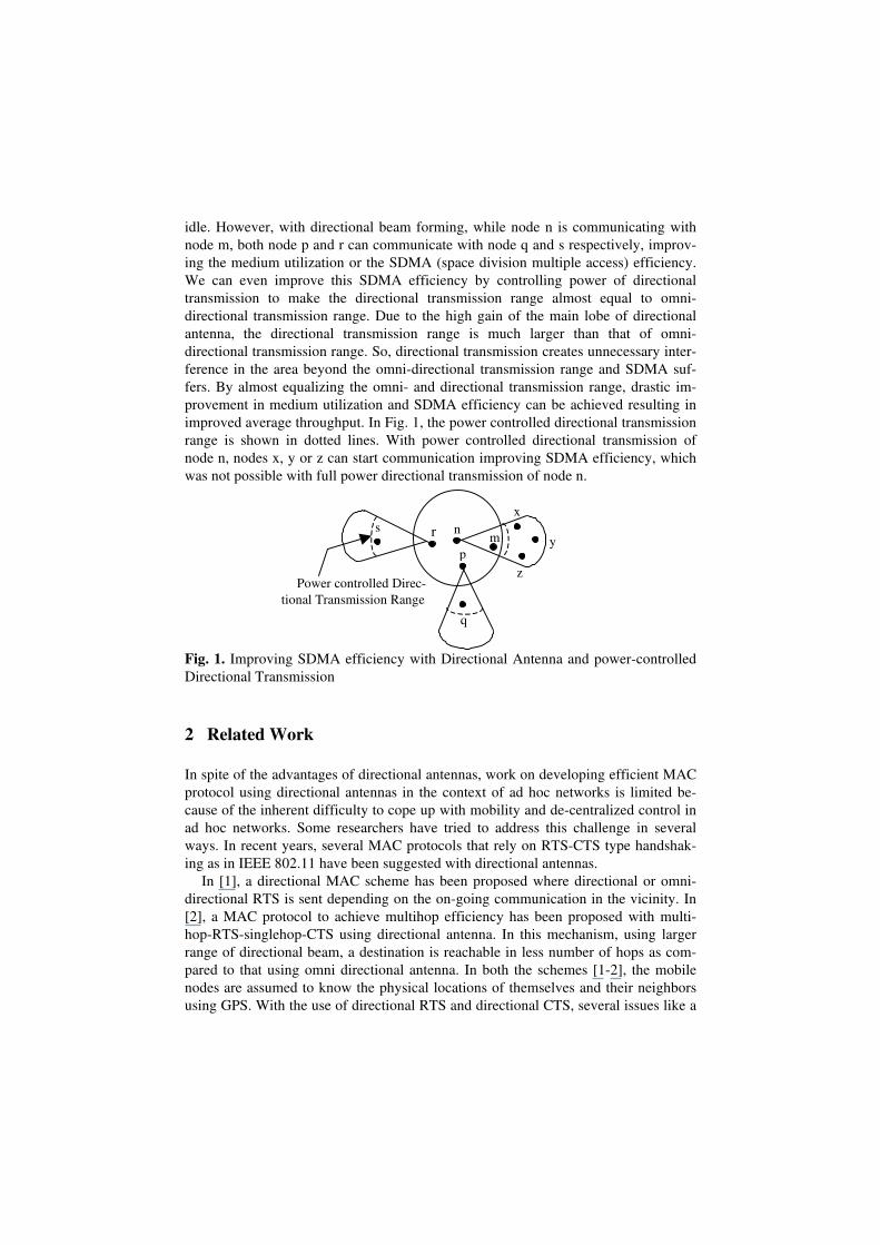
idle. However, with directional beam forming, while node n is communicating withnode m, both node p and r can communicate with node q and s respectively, improv-ing the medium utilization or the SDMA (space division multiple access) efficiency.We can even improve this SDMA efficiency by controlling power of directionaltransmission to make the directional transmission range almost equal to omni-directional transmission range. Due to the high gain of the main lobe of directionalantenna, the directional transmission range is much larger than that of omni-directional transmission range. So, directional transmission creates unnecessary inter-ference in the area beyond the omni-directional transmission range and SDMA suf-fers. By almost equalizing the omni- and directional transmission range, drastic im-provement in medium utilization and SDMA efficiency can be achieved resulting inimproved average throughput. In Fig. 1, the power controlled directional transmissionrange is shown in dotted lines. With power controlled directional transmission ofnode n, nodes x, y or z can start communication improving SDMA efficiency, whichwas not possible with full power directional transmission of node n.
Fig. 1. Improving SDMA efficiency with Directional Antenna and power-controlledDirectional Transmission
2 Related Work
In spite of the advantages of directional antennas, work on developing efficient MACprotocol using directional antennas in the context of ad hoc networks is limited be-cause of the inherent difficulty to cope up with mobility and de-centralized control inad hoc networks. Some researchers have tried to address this challenge in severalways. In recent years, several MAC protocols that rely on RTS-CTS type handshak-ing as in IEEE 802.11 have been suggested with directional antennas.
In [1], a directional MAC scheme has been proposed where directional or omni-directional RTS is sent depending on the on-going communication in the vicinity. In[2], a MAC protocol to achieve multihop efficiency has been proposed with multi-hop-RTS-singlehop-CTS using directional antenna. In this mechanism, using largerrange of directional beam, a destination is reachable in less number of hops as com-pared to that using omni directional antenna. In both the schemes [1-2], the mobilenodes are assumed to know the physical locations of themselves and their neighborsusing GPS. With the use of directional RTS and directional CTS, several issues like a
x
ynr mp
s
q
Power controlled Direc-tional Transmission Range
z
new hidden terminal problem due to asymmetry in gain & due to unheard RTS/CTS,deafness and higher directional interference, as depicted in [2], remains unsolved. In[3], the proposed MAC protocol need not know the location information; the sourceand destination nodes identify each other’s direction during omni-directional RTS-CTS exchange in an on-demand basis. It is assumed that all the neighbors of s and d,who hear this RTS-CTS dialog, will use this information to prevent interfering withthe ongoing data transmission. However, because of omnidirectional transmission ofRTS and CTS packets, this protocol provides no benefits in the spatial reuse of thewireless channel. However, it still improves the throughput over a MAC using omni-directional antennas due to the reduced amount of interference caused by the direc-tional data transmission. In our earlier work, we have developed a MAC protocol [4],where each node keeps certain neighborhood information dynamically through themaintenance of an Angle-SINR Table. In this method, in order to form AST, eachnode periodically sends a directional beacon in the form of a directional broadcast,sequentially in all direction at 30 degree interval, covering the entire 360 degreespace. The nodes, which receive these signals at different angles, determine the bestreceived signal strength and transmit the information back to the source node as datapacket with RTS/CTS handshake. However, the overhead due to control packets isvery high in this method [4].
In this paper, we will illustrate a receiver-oriented location tracking mechanism toreduce the control overhead and a simple MAC protocol for efficient medium utiliza-tion. On this directional MAC, we will show that power controlled directional trans-mission is a necessity and it improves network throughput by conserving power. Wehave done extensive performance evaluation using QualNet to demonstrate its effec-tiveness.
3 System Description
3.1 Antenna Model
There are basically two types of smart antennas used in the context of wireless net-works: switched-beam or fixed beam antennas and steerable adaptive array antennas.A switched-beam antenna generates multiple pre-defined fixed directional beam-patterns and applies one at a time when receiving a signal. In a steerable adaptivearray antenna which is more advanced than a switched beam antenna, the beamstructure adapts to Radio Frequency (RF) signal environment and directs beams to-wards the signal of interest to maximize the antenna gain, simultaneously depressingthe antenna pattern (by setting nulls) in the direction of the interferers.We have developed a wireless ad hoc network testbed using smart antenna [5] whereeach user terminal uses a small, low-cost smart antenna, known as ESPAR (Electroni-cally Steerable Passive Array Radiator) antenna. The ESPAR antenna consists of onecenter element connected to the source (the main radiator) and several surroundedparasitic elements (typically four to six passive radiators) in a circle (Fig. 2).
#0#1 #2
#3#4#5
#6
d ground plane
# 0: active rad ia tor
# 1 - 6 : pass ive rad ia tor
varac tor
coaxia l fee d through
l0
partia l cross section of each elem ent
ln
7-e lem ent overv iew
D C voltage
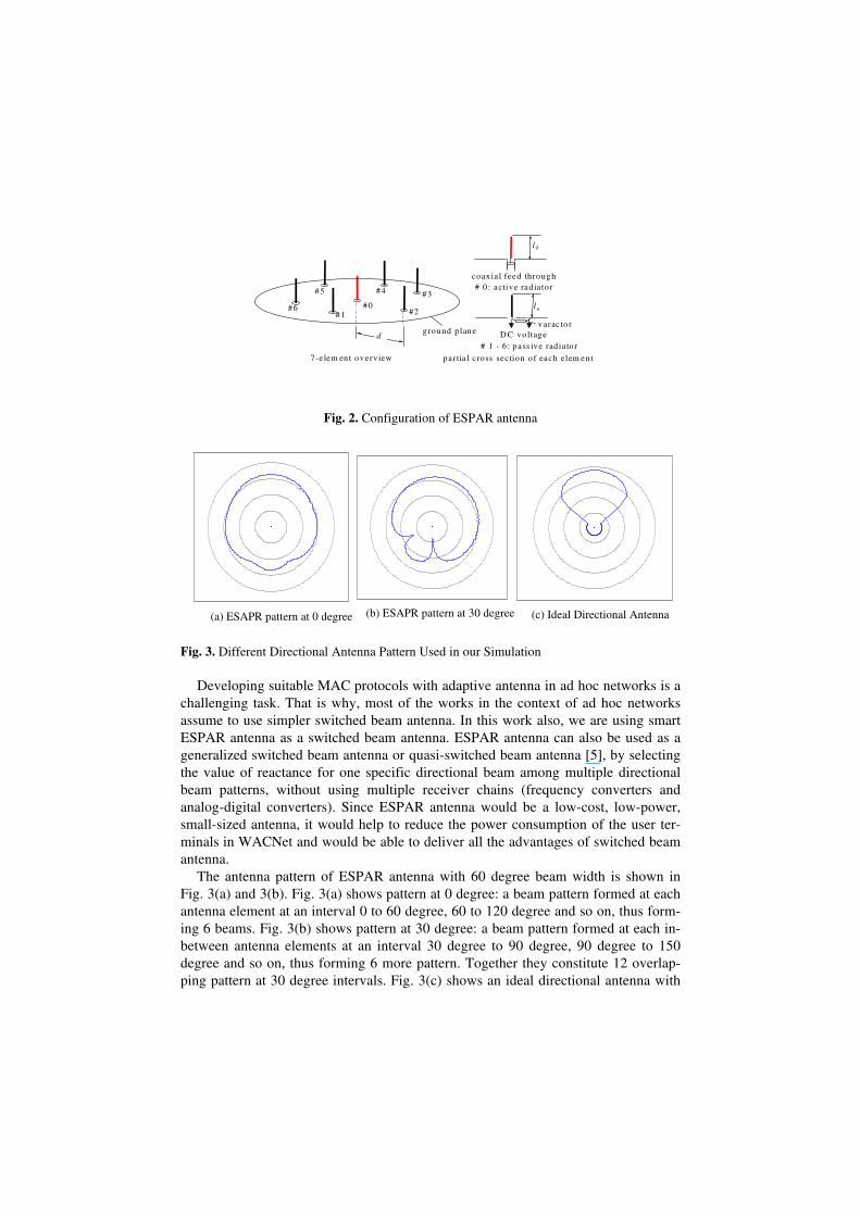
Fig. 2. Configuration of ESPAR antenna
Fig. 3. Different Directional Antenna Pattern Used in our Simulation
Developing suitable MAC protocols with adaptive antenna in ad hoc networks is achallenging task. That is why, most of the works in the context of ad hoc networksassume to use simpler switched beam antenna. In this work also, we are using smartESPAR antenna as a switched beam antenna. ESPAR antenna can also be used as ageneralized switched beam antenna or quasi-switched beam antenna [5], by selectingthe value of reactance for one specific directional beam among multiple directionalbeam patterns, without using multiple receiver chains (frequency converters andanalog-digital converters). Since ESPAR antenna would be a low-cost, low-power,small-sized antenna, it would help to reduce the power consumption of the user ter-minals in WACNet and would be able to deliver all the advantages of switched beamantenna.
The antenna pattern of ESPAR antenna with 60 degree beam width is shown inFig. 3(a) and 3(b). Fig. 3(a) shows pattern at 0 degree: a beam pattern formed at eachantenna element at an interval 0 to 60 degree, 60 to 120 degree and so on, thus form-ing 6 beams. Fig. 3(b) shows pattern at 30 degree: a beam pattern formed at each in-between antenna elements at an interval 30 degree to 90 degree, 90 degree to 150degree and so on, thus forming 6 more pattern. Together they constitute 12 overlap-ping pattern at 30 degree intervals. Fig. 3(c) shows an ideal directional antenna with
(a) ESAPR pattern at 0 degree (b) ESAPR pattern at 30 degree (c) Ideal Directional Antenna
45 degree beam-width with insignificant side-lobes. As will be demonstrated in per-formance evaluation, the performance of ideal directional antenna is the best (as ex-pected); at the same time, ESPAR performance is also comparable to that of idealdirectional antenna.
3.2 A Few Assumptions and the Rationales
♦ When the antenna of a node operating in omni-directional mode, it is capable oftransmitting and receiving signal from all direction with a gain, say, Gomni. Whileidle, a node operates in omni-directional receive mode.
♦ When the antenna of a node operating in directional mode, a node can points itsbeam (main lobe) towards a specified direction with a beam width w and with again, say Gdir (Gdir >> Gomni ).
♦ Consequently, for a given amount of input power, the transmission range Rdir
with directional antenna will be much larger than that with corresponding omni-directional antenna (Romni ).
4 A Directional MAC with Location Tracking Mechanism
In this work, our MAC protocol is basically a Receiver-oriented, Rotational SectorBased Directional MAC protocol which also serves as a Location Tracking mecha-nism. Here, each node waits in omni-directional-sensing-mode while idle. Wheneverit senses some signal above a threshold, it enters into rotational-sector-receive-mode.In rotational-sector-receive mode, node n rotates its directional antenna sequentiallyin all direction at 30-degree interval, covering the entire 360-degree space in the formof the sequential directional receiving in each direction and senses the received signalat each direction. After one full rotation, it decides the best possible direction of re-ceiving the signal with maximum received signal strength. Then it sets its beam tothat direction and receives the signal.
However, in order to enable the receiver decoding the received signal, each controlpacket is transmitted with a preceding tone with a duration such that the time to rotatea receiver’s rotational receive beam through 360 degree is little less than the durationof the tone (200 microseconds in our case). The purpose of this transmitted tone be-fore any control packet is to enable the receiver to track the best possible direction ofreceiving the signal. Once it sets its beam to that direction, the purpose of tone signalis over and subsequently the control packet is transmitted.In this proposed framework, we have used three types of omni-directional controlpackets: Beacon, RTS (Request to send) and CTS (clear to send) for medium accesscontrol. Another control packet ACK is directional control packet. Data is transmitteddirectionally after RTS/CTS handshaking is done. Beacon is a periodic signal, trans-mitted from each node at a pre-defined interval. As indicated earlier, beacon is trans-mitted with a preceding tone signal that helps the receivers to detect the best possibledirection of receiving the signal. Then each receiver sets its beam to that direction and
receives and decodes the packet. Since RTS is a broadcast packet and contains sourceaddress, nodes can decode that RTS also to form the Angle-Signal Table. So, we haveused RTS as beacon. If an RTS is sent, beacon timer is reset. The use of RTS as bea-con is advantageous at high traffic where overhead due to beacon is minimized. Thisis because, the transmitting nodes don't have to send an additional beacon to informits neighbors of its presence.
Whenever node n wants to start data communication with, say j, it checks the me-dium and if it is free, n issues an omni-directional RTS. The target node j on receivingRTS, issues omni-directional CTS. The objective of RTS/CTS here is not to inhibitthe neighbors of n and j from transmitting or receiving (as is the case with omni-directional antenna) but to inform the neighbors of j and n that j is receiving datafrom n. It also specifies the approximate duration of communication. All the neigh-boring nodes of n and j keep track of the communication between n and j by settingtheir Directional Network Allocation Vector (DNAV) towards n and j. Thus, nodes inthe neighborhood of n and j can initiate communication in other directions withoutdisturbing the existing communication between n and j. The source and destinationnodes wait for Acknowledgement and Data respectively in directional receive mode.
5 Power Controlled Directional MAC Protocol
Most researchers [6-7] used power control schemes, which suitably vary transmitpower to reduce energy consumption. But, this scheme has a shortcoming, whichincreases collisions and degrades network throughput, as pointed out in [7]. So, Junget. al. [7] proposed to transmit each data packet at maximum power level periodically,for just enough time, so that nodes in carrier sensing zone can sense it. This work hasbeen implemented using omni-directional antenna. But the scenario is completelychanged when we use directional antenna to transmit and receive signals. In [6],RTS/CTS handshake at full power is used to decide transmission power for subse-quent data and acknowledgement packets. But the marked difference between omni-and directional antenna gains has not been taken into account. So, the concept ofcontrolling power, as suggested in [6] does not work in real scenario, which is illus-trated below.
In order to demonstrate the advantage of using directional antenna in gainingSDMA efficiency, researchers usually assume that the gain of directional antennas isequal to the gain of corresponding omni-directional antenna. Under this assumption,it is easy to visualize improvement in SDMA efficiency: the coverage area or the areaof the transmission_zonen (α) of a node n forming a transmission beam with a beam-angle α (α << 360°) and a transmission range R with respect to n is αR2 /2 which ismuch low when α = 45 degree(say) compared to that when α = 360 degree ( i.e.omni-directional). If the transmission zone of a node is small, it implies that the num-ber of transmission zones that can be formed in a given area by a given number ofnodes is high, giving rise to higher SDMA efficiency. However, in real situation, thisassumption is invalid. For a given amount of input power, the range R of a user ter-minal using directional antenna will be much larger than that using omni-directional
antenna. This implies that, narrower the beam-width, higher would be the gain ofmain lobe of the directional antenna and consequently the range would be larger. So,the transmission range R is not same in both the cases and is inversely proportional toα. Consequently, SDMA efficiency will not improve as much as it is expected. Forexample, in Fig. 1, nodes x, y and z are outside the omni-directional transmissionrange of node n, but in the directional transmission range of node n. So, even if theydon't receive RTS from node n, they are captured by the directional transmission ofnode n and cannot start a communication in other directions. On the other hand, sincenode m is within omni-directional transmission range of node n, proper reception ofsignal at node m does not require higher directional transmission range of node ntowards the direction of node m. If we reduce the power to reduce the directionaltransmission range, as shown in dotted line, nodes x, y and z can start communicationin directions other than the direction of node m which is blocked by DNAV. Thus,SDMA efficiency is improved resulting in increased throughput.
In this paper, we study power control for the purpose of improving SDMA effi-ciency and as a result energy consumption is minimized. We propose a two-leveltransmit power control mechanism in order to approximately equalize the transmis-sion range R of an antenna operating at omni-directional and directional mode. Inother words, if P is the full power used during omni-directional transmission, a re-duced power level p will be used during directional transmission so as to equalize therange of transmission approximately in both the cases. This will not only improve theSDMA efficiency but also help to conserve the power of the transmitting node duringdirectional transmission of data. In this scheme, control packets like beacon, RTS andCTS are omni-directional and use full power P for their transmission. On the otherhand, directional transmission of ACK (Acknowledgement) packets and data packetsare done with reduced power p.
Since directional transmission range depends mainly on antenna pattern and thegain of its main lobe, the reduced power p will be different in different antenna pat-terns. If a node knows with which antenna it is equipped with, it can control its poweraccordingly during directional transmission to approximately equalize its directionaltransmission range with omni-directional transmission range.
6 Performance Evaluation
6.1 Simulation Environment
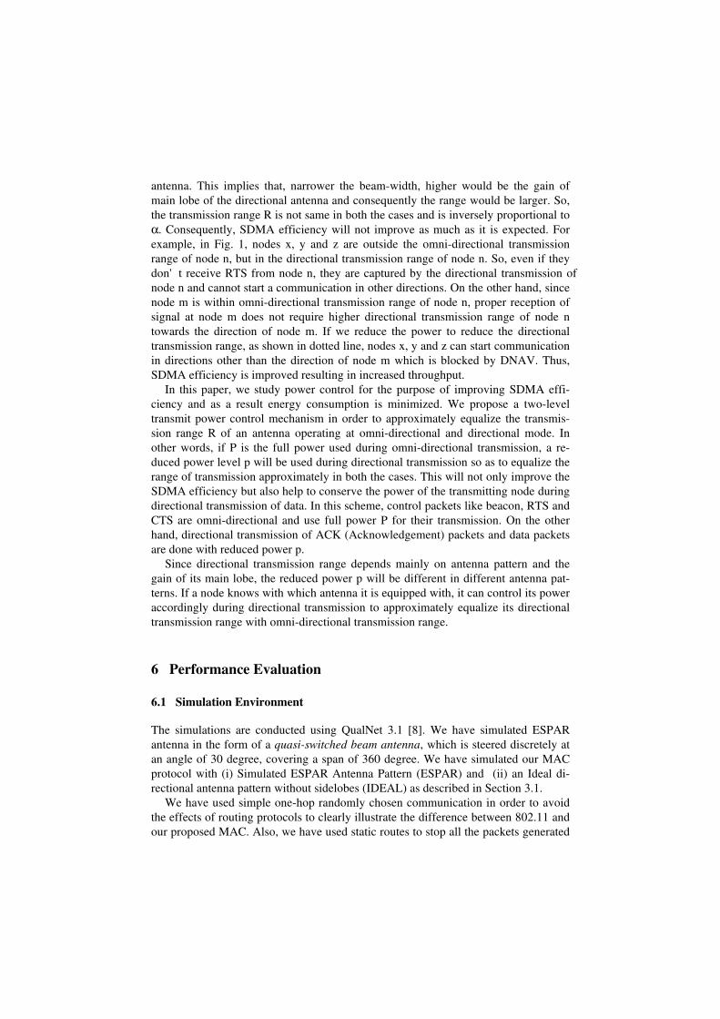
The simulations are conducted using QualNet 3.1 [8]. We have simulated ESPARantenna in the form of a quasi-switched beam antenna, which is steered discretely atan angle of 30 degree, covering a span of 360 degree. We have simulated our MACprotocol with (i) Simulated ESPAR Antenna Pattern (ESPAR) and (ii) an Ideal di-rectional antenna pattern without sidelobes (IDEAL) as described in Section 3.1.
We have used simple one-hop randomly chosen communication in order to avoidthe effects of routing protocols to clearly illustrate the difference between 802.11 andour proposed MAC. Also, we have used static routes to stop all the packets generated
by any routing protocol, whether it is proactive or reactive. In our simulation, westudied the performance of the proposed MAC protocol in comparison with the ex-isting omnidirectional 802.11 MAC protocol by varying the Data Rate and number ofsimultaneous communications. In studying our MAC protocol, we have used differentantenna patterns as described above to ensure the robustness of our proposed MACprotocol. In doing this, we have used ESPAR antenna as one of the antenna patterns,to evaluate the performance of the ESPAR antenna as well.
The set of parameters used are listed in Table I.
Table 1. Parameters used in Simulation
Parameters ValueArea 1000 x 1000 mNumber of nodes 40Transmission Power 15 dBmReceiving Threshold -81.0 dBmSensing Threshold -91.0 dBmData Rate 2MbpsPacket Size 512 bytesDuration of Preceding Tone 200 microsecondsCBR Packet Injection Interval 2 ms to 50 msNumber of simultaneous communication 4 to 12Simulation Time 5 minutes
6.2 Results and Discussions
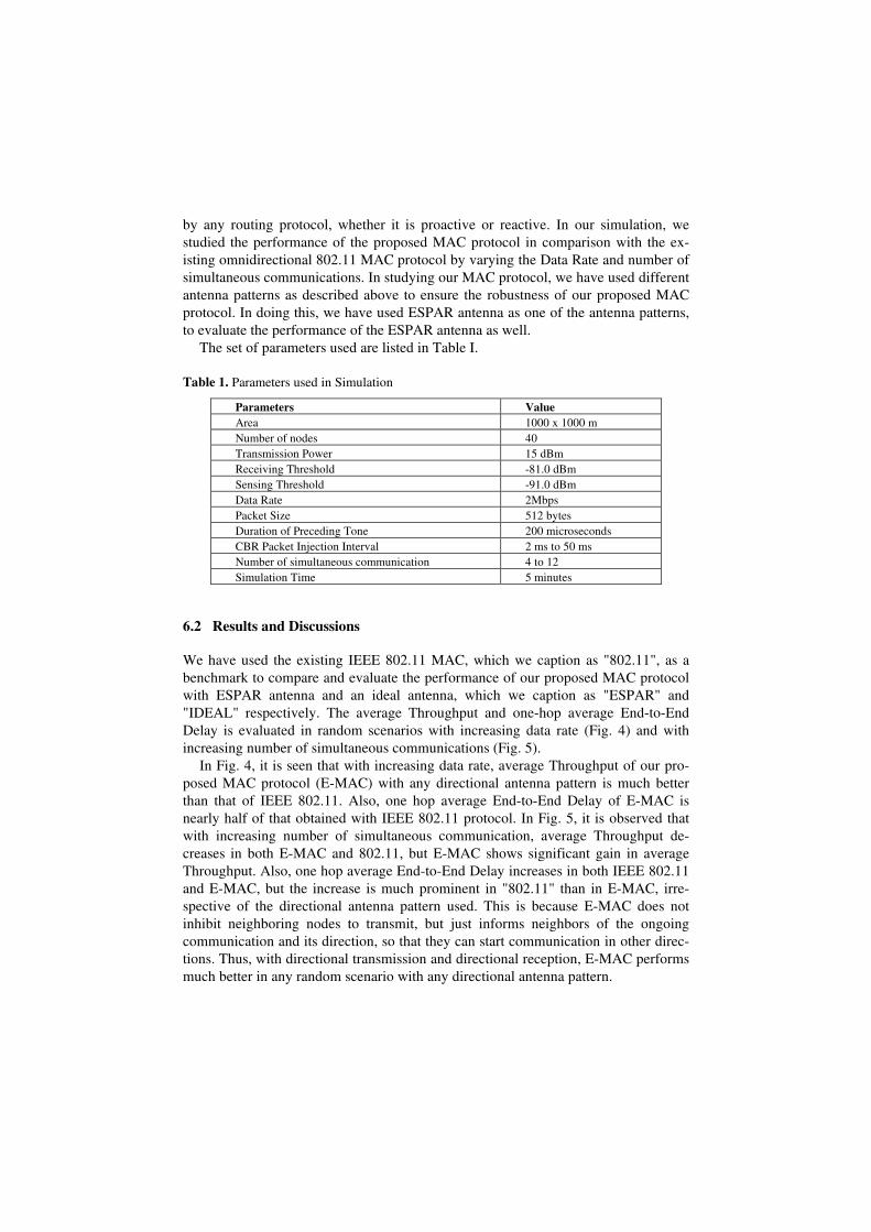
We have used the existing IEEE 802.11 MAC, which we caption as "802.11", as abenchmark to compare and evaluate the performance of our proposed MAC protocolwith ESPAR antenna and an ideal antenna, which we caption as "ESPAR" and"IDEAL" respectively. The average Throughput and one-hop average End-to-EndDelay is evaluated in random scenarios with increasing data rate (Fig. 4) and withincreasing number of simultaneous communications (Fig. 5).
In Fig. 4, it is seen that with increasing data rate, average Throughput of our pro-posed MAC protocol (E-MAC) with any directional antenna pattern is much betterthan that of IEEE 802.11. Also, one hop average End-to-End Delay of E-MAC isnearly half of that obtained with IEEE 802.11 protocol. In Fig. 5, it is observed thatwith increasing number of simultaneous communication, average Throughput de-creases in both E-MAC and 802.11, but E-MAC shows significant gain in averageThroughput. Also, one hop average End-to-End Delay increases in both IEEE 802.11and E-MAC, but the increase is much prominent in "802.11" than in E-MAC, irre-spective of the directional antenna pattern used. This is because E-MAC does notinhibit neighboring nodes to transmit, but just informs neighbors of the ongoingcommunication and its direction, so that they can start communication in other direc-tions. Thus, with directional transmission and directional reception, E-MAC performsmuch better in any random scenario with any directional antenna pattern.
Comparison of Average Throughput
0
50
100
150
200
250
300
0 0.5 1 1.5 2 2.5
Data Rate (Mbps)
Ave
rage
Thr
ough
put
(Kbp
s) 802.11ESPARIDEAL
Comparison of One Hop Average End-to-End Delay
0
5
10
15
20
0 0.5 1 1.5 2 2.5
Data Rate (Mbps)
One
Hop
Ave
rage
End
-to-
End
Del
ay (s
)
802.11ESPARIDEAL
Fig. 4. Performance Evaluation of the proposed MAC protocol with directional antenna withincreasing data rate
Comparison of Average Throughput
050
100150200250300350400450
0 5 10 15
Number of Simultaneous Communication
Ave
rage
Thr
ough
put
(Kbp
s) 802.11ESPARIDEAL
Comparison of One Hop Average End-to-End Delay
0
5
10
15
20
25
0 5 10 15
Number of Simultaneous Communication
One
Hop
Ave
rage
End
-to-
End
Del
ay (s
)802.11ESPARIDEAL
Fig. 5. Performance Evaluation of the proposed MAC protocol with directional antenna withincreasing number of simultaneous communication
Comparison of Average Transmission Energy Consumption
00.0010.0020.0030.0040.0050.0060.007
ESPAR(0.55*Full-
Power)
ESPAR (Full-Power)
IDEAL(0.20*Full-
Power)
IDEAL (Full-Power)A
vera
ge T
rans
mis
sion
Ene
rgy
Con
sum
ptio
n (m
WH
r)
Comparison of Average Throughput
050
100150200250300350400
ESPAR(0.55*Full-
Power)
ESPAR (Full-Power)
IDEAL(0.20*Full-
Power)
IDEAL (Full-Power)
Ave
rage
Thr
ough
put (
Kbp
s)
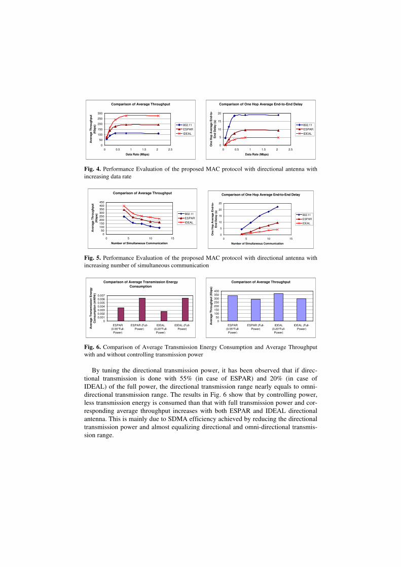
Fig. 6. Comparison of Average Transmission Energy Consumption and Average Throughputwith and without controlling transmission power
By tuning the directional transmission power, it has been observed that if direc-tional transmission is done with 55% (in case of ESPAR) and 20% (in case ofIDEAL) of the full power, the directional transmission range nearly equals to omni-directional transmission range. The results in Fig. 6 show that by controlling power,less transmission energy is consumed than that with full transmission power and cor-responding average throughput increases with both ESPAR and IDEAL directionalantenna. This is mainly due to SDMA efficiency achieved by reducing the directionaltransmission power and almost equalizing directional and omni-directional transmis-sion range.

7 Conclusion
Use of directional antenna in ad hoc wireless network can drastically improve systemperformance, if proper MAC protocol can be designed. The success of the MACprotocol highly depends on the directional antenna pattern. Currently, the ESPARantenna is under development, where we are trying to modify the beam-pattern to getmaximum gain from E-MAC. The location tracking mechanism as done in our pro-posed MAC protocol can be utilized in designing efficient Routing protocol. Pres-ently, we are working on efficient controlling of transmission power dynamically toimprove the proposed MAC performance.
8 Acknowledgements
This research was supported in part by the Telecommunications Advancement Organiza-tion of Japan.
References
1. Y.B. Ko, V. Shankarkumar and N. H. Vaidya, ``Medium access control protocols usingdirectional antennas in ad hoc networks,'' Proc. Of the IEEE INFOCOM 2000, March2000.
2. Romit Roy Choudhury, Xue Yang, Nitin H. Vaidya, Ram Ramanathan, “Using directionalantennas for medium access control in ad hoc networks” Proceedings of the eighth annualinternational conference on Mobile computing and networking September 2002
3. Nasipuri, S. Ye, J. You and R.E. Hiromoto, “A MAC Protocol for Mobile Ad Hoc Net-works Using Directional Antennas”, Proc of the IEEE WCNC 2000.
4. S. Bandyopadhyay, K. Hasuike, S. Horisawa, S. Tawara, "An Adaptive MAC Protocol forWireless Ad Hoc Community Network (WACNet) Using Electronically Steerable PassiveArray Radiator Antenna", Proc of the GLOBECOM 2001, November 25-29, 2001, SanAntonio, Texas, USA
5. T. Ueda, K. Masayama, S. Horisawa, M. Kosuga, K. Hasuike, “Evaluating the Perform-ance of Wireless Ad Hoc Network Testbed With Smart Antenna”, Fourth IEEE Confer-ence on Mobile and Wireless Communication Networks (MWCN2002), September 2002
6. Asis Nasipuri, Kai Li, and Uma Reddy Sappidi, “Power Consumption and throughput inMobile Ad Hoc Networks using Directional Antennas” in Proceedings of the IEEE Inter-national Conference on Computer Communication and Networks (ICCCN2002), October14-16, 2002, Miami, Florida.
7. Eun-Sun Jung and Nitin Vaidya, "A Power Control MAC Protocol for Ad Hoc Net-works", ACM International Conference on Mobile Computing and Networking (Mobi-Com), September 2002.
8. QualNet Simulator Version 3.1, Scalable Network Technologies, www.scalable-networks.com