A numerical tool for thermo-mechanical analysis of multilayer stepped structures
18
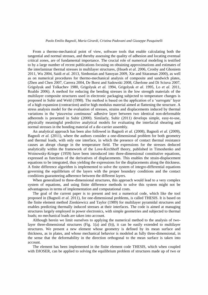
Structural Engineering and Mechanics, Vol. 48, No. 6 (2013) 000-000 DOI: http://dx.doi.org/10.12989/sem.2013.48.6.000 000 Copyright © 2013 Techno-Press, Ltd. http://www.techno-press.org/?journal=sem&subpage=8 ISSN: 1225-4568 (Print), 1598-6217 (Online) A numerical tool for thermo-mechanical analysis of multilayer stepped structures Paolo Emilio Bagnoli 1 , Maria Girardi 2 , Cristina Padovani 2 and Giuseppe Pasquinelli 2 1 Department of Information Engineering, University of Pisa, Via G. Caruso 16 56122, Pisa, Italy 2 Institute of Information Science and Technologies “A. Faedo”, National Research Council of Italy ISTI-CNR, Via G. Moruzzi 1, 56124, Pisa, Italy (Received June 6, 2012, Revised November 5, 2013, Accepted November 9, 2013) Abstract. An integrated simulation tool for multilayer stepped pyramidal structures is presented. The tool, based on a semi-analytical mathematical strategy, is able to calculate the temperature distributions and thermal stresses at the interfaces between the layers of such structures. The core of the thermal solver is the analytical simulator for power electronic devices, DJOSER, which has been supplemented with a mechanical solver based on the finite-element method. To this end, a new ele-ment is proposed whose geometry is defined by its mean surface and thickness, just as in a plate. The resulting mechanical model is fully three-dimensional, in the sense that the deformability in the direction orthogonal to the mean surface is taken into account. The dedicated finite element code developed for solving the equilibrium problem of structures made up of two or more superimposed plates subjected to thermal loads is applied to some two-layer samples made of silicon and copper. Comparisons performed with the results of standard finite element analyses using a large number of brick elements reveal the soundness of the strategy employed and the accuracy of the tool developed. Keywords: multilayer structures, thermal stresses, finite element method, power electronic devices 1. Introduction Power electronic devices are composed of structures made up of layers with different geometrical and thermo-mechanical properties. These structures are subjected to high thermal loads, which give rise to stress distributions that can damage the adhesive films between the layers and lead to debonding. The problem of the thermal analysis of such structures has been addressed in (Bagnoli et al. 2007a, Bagnoli et al. 2007b, Montesi et al. 2004), where DJOSER, a tool for computing the steady-state temperature mapping of multilayer assembly structures for power electronics, is described. The simplicity and high degree of standardization of power assemblies, which in most cases can be modeled as multilayer, stepped pyramidal structures with homogeneous layers and rectangular geometries, enable fruitful application of DJOSER, which is a time saving, user-friendly code based on an analytical approach. Corresponding author, Ph.D., E-mail: [email protected]
Transcript of A numerical tool for thermo-mechanical analysis of multilayer stepped structures
Structural Engineering and Mechanics, Vol. 48, No. 6 (2013) 000-000
DOI: http://dx.doi.org/10.12989/sem.2013.48.6.000 000
Copyright © 2013 Techno-Press, Ltd.
http://www.techno-press.org/?journal=sem&subpage=8 ISSN: 1225-4568 (Print), 1598-6217 (Online)
A numerical tool for thermo-mechanical analysis of multilayer stepped structures
Paolo Emilio Bagnoli1, Maria Girardi2, Cristina Padovani2 and
Giuseppe Pasquinelli2
1Department of Information Engineering, University of Pisa, Via G. Caruso 16 56122, Pisa, Italy
2Institute of Information Science and Technologies “A. Faedo”, National Research Council of Italy ISTI-CNR,
Via G. Moruzzi 1, 56124, Pisa, Italy
(Received June 6, 2012, Revised November 5, 2013, Accepted November 9, 2013)
Abstract. An integrated simulation tool for multilayer stepped pyramidal structures is presented. The tool, based on a semi-analytical mathematical strategy, is able to calculate the temperature distributions and thermal stresses at the interfaces between the layers of such structures. The core of the thermal solver is the analytical simulator for power electronic devices, DJOSER, which has been supplemented with a mechanical solver based on the finite-element method. To this end, a new ele-ment is proposed whose geometry is defined by its mean surface and thickness, just as in a plate. The resulting mechanical model is fully three-dimensional, in the sense that the deformability in the direction orthogonal to the mean surface is taken into account. The dedicated finite element code developed for solving the equilibrium problem of structures made up of two or more superimposed plates subjected to thermal loads is applied to some two-layer samples made of silicon and copper. Comparisons performed with the results of standard finite element analyses using a large number of brick elements reveal the soundness of the strategy employed and the accuracy of the tool developed.
Keywords: multilayer structures, thermal stresses, finite element method, power electronic devices
1. Introduction
Power electronic devices are composed of structures made up of layers with different
geometrical and thermo-mechanical properties. These structures are subjected to high thermal
loads, which give rise to stress distributions that can damage the adhesive films between the layers
and lead to debonding. The problem of the thermal analysis of such structures has been addressed
in (Bagnoli et al. 2007a, Bagnoli et al. 2007b, Montesi et al. 2004), where DJOSER, a tool for
computing the steady-state temperature mapping of multilayer assembly structures for power
electronics, is described. The simplicity and high degree of standardization of power assemblies,
which in most cases can be modeled as multilayer, stepped pyramidal structures with
homogeneous layers and rectangular geometries, enable fruitful application of DJOSER, which is
a time saving, user-friendly code based on an analytical approach.
Corresponding author, Ph.D., E-mail: [email protected]
Paolo Emilio Bagnoli, Maria Girardi, Cristina Padovani and Giuseppe Pasquinelli
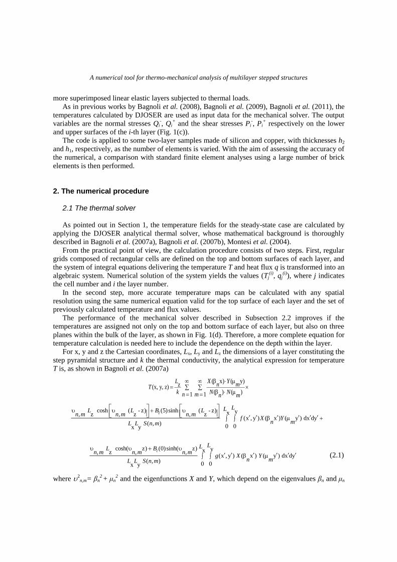
From a thermo-mechanical point of view, software tools that enable calculating both the
tangential and normal stresses, and thereby assessing the quality of adhesion and locating eventual
critical zones, are of fundamental importance. The crucial role of numerical modeling is testified
to by a large number of recent publications focusing on obtaining approximations and estimates of
the interlaminar thermal stresses in multilayer structures, (Hsueh et al. 2006, Crosby and Ghoniem
2011, Wu 2004, Saidi et al. 2013, Simhonian and Sanoyan 2009, Xie and Sitaraman 2000), as well
as on numerical procedures for thermo-mechanical analysis of composite and sandwich plates,
(Zhen and Chen 2007, Carrera 2004, De Borst and Sadowski 2008, Gherlone and Di Sciuva 2007,
Grigolyuk and Tolkachev 1980, Grigolyuk et al. 1994, Grigolyuk et al. 1995, Lo et al. 2011,
Roaldo 2006). A method for reducing the bending stresses in the low strength materials of the
multilayer composite structures used in electronic packaging subjected to temperature changes is
proposed in Suhir and Weld (1998). The method is based on the application of a „surrogate‟ layer
of a high expansion (contraction) and/or high modulus material aimed at flattening the structure. A
stress analysis model for the evaluation of stresses, strains and displacements induced by thermal
variations in the „piecewise continuous‟ adhesive layer between two identical non-deformable
adherends is presented in Suhir (2000). Similarly, Suhir (2011) develops simple, easy-to-use,
physically meaningful predictive analytical models for evaluating the interfacial shearing and
normal stresses in the bonding material of a die-carrier assembly.
An analytical approach has been also followed in Bagnoli et al. (2008), Bagnoli et al. (2009),
Bagnoli et al. (2011), where the authors consider a one-dimensional problem for both geometry
and thermal loads, with only one interface, in which the presence of contact thermal resistance
causes an abrupt change in the temperature field. The expressions for the stresses deduced
analytically within the framework of the Love-Kirchhoff theory, published in Timoshenko and
Woinowsky-Krieger (1959) have been introduced into three-dimensional constitutive equations,
expressed as functions of the derivatives of displacements. This enables the strain-displacement
equations to be integrated, thus yielding the expressions for the displacements along the thickness.
A finite difference algorithm is implemented to solve the system of integro-differential equations
governing the equilibrium of the layers with the proper boundary conditions and the contact
conditions guaranteeing adherence between the different layers.
When generalized to three-dimensional structures, this approach would lead to a very complex
system of equations, and using finite difference methods to solve this system might not be
advantageous in terms of implementation and computational costs.
The goal of the current paper is to present and test a numerical code, which like the tool
proposed in (Bagnoli et al. 2011), for one-dimensional problems, is called THESIS. It is based on
the finite element method Zienkiewicz and Taylor (1989) for multilayer pyramidal structures and
enables predicting thermally induced stresses at their interfaces. The code is aimed at managing
structures largely employed in power electronics, with simple geometries and subjected to thermal
loads; no mechanical loads are taken into account.
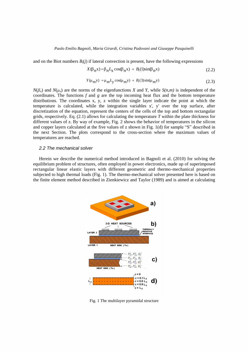
Although herein we limit ourselves to applying the numerical method to the analysis of two-
layer three-dimensional structures (Fig. 1(a) and (b)), it can be easily extended to multilayer
structures. We present a new element whose geometry is defined by its mean surface and
thickness, as in plates, and whose mechanical behavior is modeled as fully three-dimensional, in
the sense that the deformability in the direction orthogonal to the mean surface is taken into
account.
The element has been implemented in the finite element code THESIS, which when coupled
with DJOSER, can be applied to solving the equilibrium problem of structures made up of two or
A numerical tool for thermo-mechanical analysis of multilayer stepped structures
more superimposed linear elastic layers subjected to thermal loads.
As in previous works by Bagnoli et al. (2008), Bagnoli et al. (2009), Bagnoli et al. (2011), the
temperatures calculated by DJOSER are used as input data for the mechanical solver. The output
variables are the normal stresses Qi-, Qi
+ and the shear stresses Pi
-, Pi
+ respectively on the lower
and upper surfaces of the i-th layer (Fig. 1(c)).
The code is applied to some two-layer samples made of silicon and copper, with thicknesses h2
and h1, respectively, as the number of elements is varied. With the aim of assessing the accuracy of
the numerical, a comparison with standard finite element analyses using a large number of brick
elements is then performed.
2. The numerical procedure
2.1 The thermal solver As pointed out in Section 1, the temperature fields for the steady-state case are calculated by
applying the DJOSER analytical thermal solver, whose mathematical background is thoroughly
described in Bagnoli et al. (2007a), Bagnoli et al. (2007b), Montesi et al. (2004).
From the practical point of view, the calculation procedure consists of two steps. First, regular
grids composed of rectangular cells are defined on the top and bottom surfaces of each layer, and
the system of integral equations delivering the temperature T and heat flux q is transformed into an
algebraic system. Numerical solution of the system yields the values (Tj(i)
, qj(i)
), where j indicates
the cell number and i the layer number.
In the second step, more accurate temperature maps can be calculated with any spatial
resolution using the same numerical equation valid for the top surface of each layer and the set of
previously calculated temperature and flux values.
The performance of the mechanical solver described in Subsection 2.2 improves if the
temperatures are assigned not only on the top and bottom surface of each layer, but also on three
planes within the bulk of the layer, as shown in Fig. 1(d). Therefore, a more complete equation for
temperature calculation is needed here to include the dependence on the depth within the layer.
For x, y and z the Cartesian coordinates, Lx, Ly and Lz the dimensions of a layer constituting the
step pyramidal structure and k the thermal conductivity, the analytical expression for temperature
T is, as shown in Bagnoli et al. (2007a)
( x) ( y)z(x, y, z)
( ) ( )1 1
X YLn mT
k N Nn m n m
cosh ( - z) (5)sinh ( - z) yx, z , z , z (x , y ) ( x ) ( y ) dx dy
( , ) 0 0x y
i
LLL L B Ln m n m n m
f X Yn mL L S n m
cosh( z) (0)sinh( z) yx, z , ,(x , y ) ( x ) ( y ) dx dy
( , )0 0x y
i
LLL Bn m n m n m
g X Yn mL L S n m
(2.1)
where 2n,m= βn
2 + μn
2 and the eigenfunctions X and Y, which depend on the eigenvalues βn and μn
Paolo Emilio Bagnoli, Maria Girardi, Cristina Padovani and Giuseppe Pasquinelli
and on the Biot numbers Bi(j) if lateral convection is present, have the following expressions
( x) cos( x) (1)sin( x)x iX L Bn n n n
(2.2)
( y) cos( y) (3)sin( y)y iY L Bm m m m
(2.3)
N(βn) and N(μn) are the norms of the eigenfunctions X and Y, while S(n,m) is independent of the
coordinates. The functions f and g are the top incoming heat flux and the bottom temperature
distributions. The coordinates x, y, z within the single layer indicate the point at which the
temperature is calculated, while the integration variables x', y' over the top surface, after
discretization of the equation, represent the centers of the cells of the top and bottom rectangular
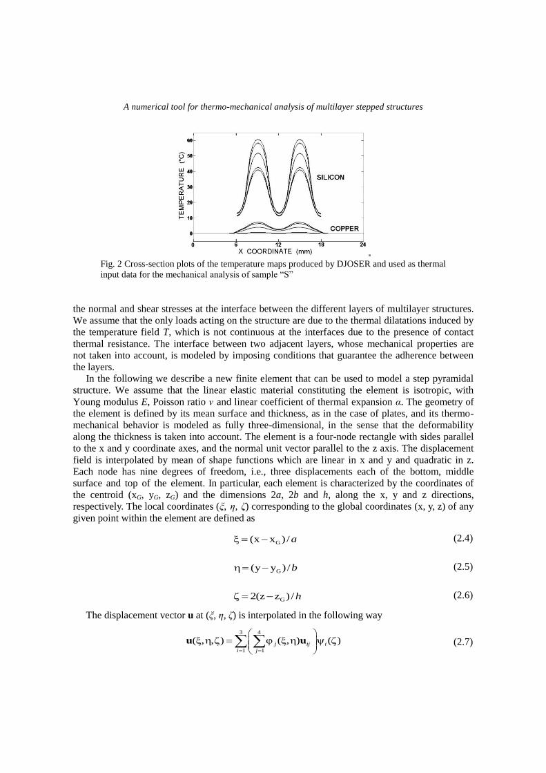
grids, respectively. Eq. (2.1) allows for calculating the temperature T within the plate thickness for
different values of z. By way of example, Fig. 2 shows the behavior of temperatures in the silicon
and copper layers calculated at the five values of z shown in Fig. 1(d) for sample “S” described in
the next Section. The plots correspond to the cross-section where the maximum values of
temperatures are reached.
2.2 The mechanical solver
Herein we describe the numerical method introduced in Bagnoli et al. (2010) for solving the
equilibrium problem of structures, often employed in power electronics, made up of superimposed
rectangular linear elastic layers with different geometric and thermo-mechanical properties
subjected to high thermal loads (Fig. 1). The thermo-mechanical solver presented here is based on
the finite element method described in Zienkiewicz and Taylor (1989) and is aimed at calculating
Fig. 1 The multilayer pyramidal structure
A numerical tool for thermo-mechanical analysis of multilayer stepped structures
Fig. 2 Cross-section plots of the temperature maps produced by DJOSER and used as thermal
input data for the mechanical analysis of sample “S”
the normal and shear stresses at the interface between the different layers of multilayer structures.
We assume that the only loads acting on the structure are due to the thermal dilatations induced by
the temperature field T, which is not continuous at the interfaces due to the presence of contact
thermal resistance. The interface between two adjacent layers, whose mechanical properties are
not taken into account, is modeled by imposing conditions that guarantee the adherence between
the layers.
In the following we describe a new finite element that can be used to model a step pyramidal
structure. We assume that the linear elastic material constituting the element is isotropic, with
Young modulus E, Poisson ratio ν and linear coefficient of thermal expansion α. The geometry of
the element is defined by its mean surface and thickness, as in the case of plates, and its thermo-
mechanical behavior is modeled as fully three-dimensional, in the sense that the deformability
along the thickness is taken into account. The element is a four-node rectangle with sides parallel
to the x and y coordinate axes, and the normal unit vector parallel to the z axis. The displacement
field is interpolated by mean of shape functions which are linear in x and y and quadratic in z.
Each node has nine degrees of freedom, i.e., three displacements each of the bottom, middle
surface and top of the element. In particular, each element is characterized by the coordinates of
the centroid (xG, yG, zG) and the dimensions 2a, 2b and h, along the x, y and z directions,
respectively. The local coordinates (ξ, η, ζ) corresponding to the global coordinates (x, y, z) of any
given point within the element are defined as
G(x x )/a (2.4)
G(y y )/b (2.5)
G2(z z )/h (2.6)
The displacement vector u at (ξ, η, ζ) is interpolated in the following way
3 4
1 1
( , , ) ( , ) ( ) u uj ij i
i j
(2.7)
Paolo Emilio Bagnoli, Maria Girardi, Cristina Padovani and Giuseppe Pasquinelli
where uij is the displacement vector of the j-th node of the bottom (i = 1), the top (i = 2) and the
middle surface (i = 3) of the element.
The bilinear in-plane shape functions υi are
1( , ) (1 )(1 ) / 4 (2.8)
2( , ) (1 )(1 ) / 4 (2.9)
3( , ) (1 )(1 ) /4 (2.10)
4( , ) (1 )(1 ) /4 (2.11)
and the quadratic out of plane shape functions ψj are
1( ) (1 ) / 2 (2.12)
2( ) (1 ) /2 (2.13)
3( ) (1 )(1 ) (2.14)
For u , the gradient of the displacement, and T
u , its transpose, the vector ε of the engineering
components of the infinitesimal strain tensor ( u +T
u )/2 at any point in the element can be
easily calculated by taking into account expression (2.7). For ux, u
y and u
z, the Cartesian
components of vector u, we have
3 4x
xx
1 1
1 u
j
ij i
i ja
(2.15)
3 4y
yy
1 1
1 u
j
ij i
i jb
(2.16)
3 4z
zz
1 1
2 u
ij ij
i jh
(2.17)
3 4y
xy
1 1
1 u
j
ij i
i ja
3 4
x
1 1
1 u
j
ij i
i jb
(2.18)
3 4z
xz
1 1
1 u
j
ij i
i ja
3 4
x
1 1
2 u
ij ij
i jh
(2.19)
3 4z
yz
1 1
1 u
j
ij i
i jb
3 4
y
1 1
2 u
ij ij
i jh
(2.20)
A numerical tool for thermo-mechanical analysis of multilayer stepped structures
Eqs. (2.15)-(2.20) can be rewritten as follows
ε Bδ (2.21)
where B is the strain matrix containing the derivatives of the shape functions, and δ is the vector of
the nodal displacements uij of the element. Denoting by ζ the vector of the engineering component
of the stress tensor, σ =(σxx, σyy, σzz, τxy, τxz, τyz)T, within the element we have
0 ζ D ε ε (2.22)
where D is the matrix depending on the elastic constants E and ν, and ε0 is the vector of the
engineering components of the thermal dilatation α(T−T0)I, with I the identity tensor and T0 the
reference temperature. As for calculation of the stiffness matrix, a four point Gauss-Legendre
scheme is used for numerical integration in the (ξ, η) plane, while integration along the thickness is
carried out analytically.
To define the geometry of the structure it is sufficient to input, for each layer, the coordinates
of two non-adjacent vertices and the thickness h. Each layer of the pyramidal structure is modeled
by one or more strata of elements (the number of strata must be specified by the user). The mesh
of finite elements used for the thermo-mechanical analysis matches the grid of cells used by
DJOSER. Regarding the boundary conditions applied to the whole structure, we assume that the
base of the structure is clamped, thus precluding any displacements of the bottom surface of the
lowest elements. Two superimposed elements are connected by assuming the top displacements of
the lower element equal the bottom displacements of the upper element. This approach does not
take into account the deformability of the adhesive layer, and any eventual debonding phenomena
can be detected by means of an analysis of the shear and normal stresses.
3. Applications and results
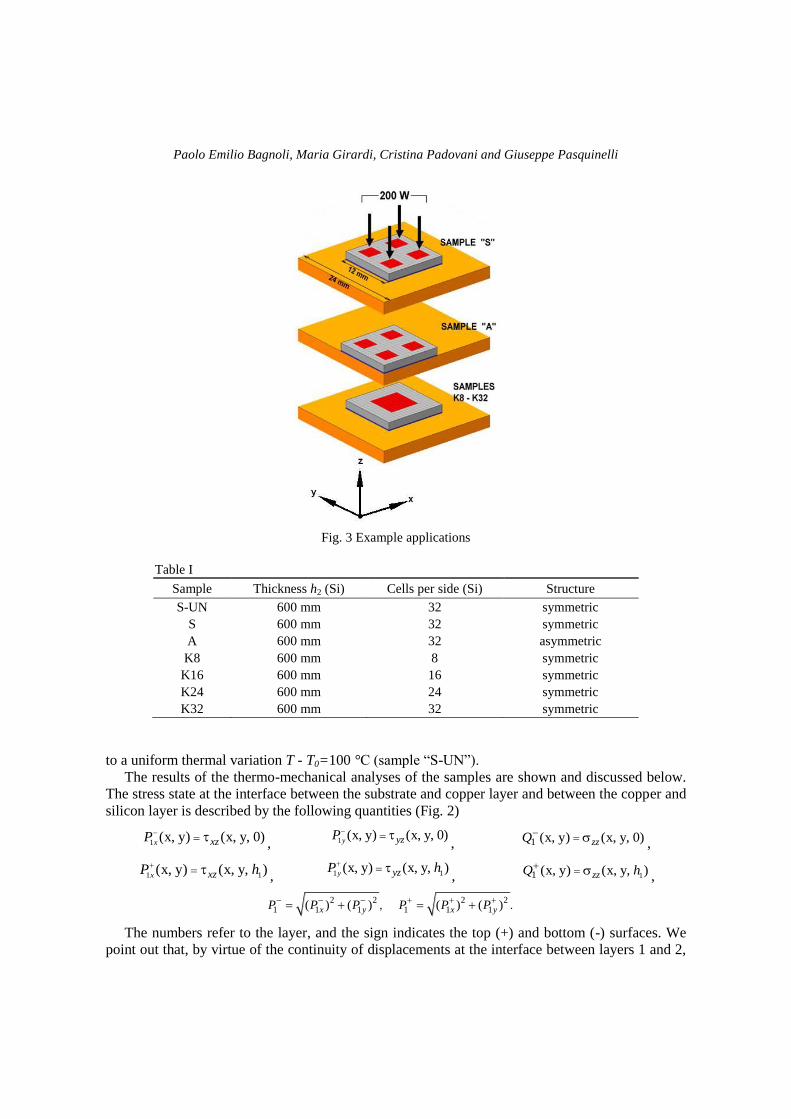
The numerical tool described in Section 2 has been applied to the set of samples shown in Fig.
3, each composed of two square slabs with different dimensions: a semiconductor device substrate
(12 mm wide and 0.6 mm thick) made of silicon (layer 2, Fig. 2(b)) and a lower heat dissipating
frame (24 mm wide and 1 mm thick) made of copper (layer 1, Fig. 2(b)).
With the aim of illustrating the accuracy of the proposed numerical procedure, a comparison is
presented with the results of standard finite element analyses using brick elements. The
dependence of the numerical results on the number of elements in the grids is then investigated.
The two-dimensional heat sources, dissipating a total of 200 W, are localized on the top silicon
surface. They are arranged in four square islands in the symmetric (“S”) and asymmetric (“A”)
samples and in one central island in the “K” series (see Fig. 3). The samples belonging to the “K”
group differ from each other in the 2-D cell densities used by both the thermal and mechanical
solvers. The main properties of all samples are reported in Table I. The number of cells per side in
the copper layer is twice that of the silicon one.
The two layers of all the samples are separated by a thermally resistive interface, representing a
gluing or fixing film, whose specific contact thermal resistance Rc is 10 mm2 °C/W. As for the
thermo-mechanical properties, we have E = 1.5 105 N/mm
2, ν = 0.17, and α = 8.0 10
-6 °C
-1 for the
silicon, and E = 1.1305 N/mm
2, ν = 0.34, and α = 1.7 10
-5 °C
-1 for the copper.
Table I also includes a further sample, with the same characteristics as sample “S”, on which an
analysis has been conducted by removing the heat sources and considering the structure subjected
Paolo Emilio Bagnoli, Maria Girardi, Cristina Padovani and Giuseppe Pasquinelli
Fig. 3 Example applications
Table I
Sample Thickness h2 (Si) Cells per side (Si) Structure
S-UN 600 mm 32 symmetric
S 600 mm 32 symmetric
A 600 mm 32 asymmetric
K8 600 mm 8 symmetric
K16 600 mm 16 symmetric
K24 600 mm 24 symmetric
K32 600 mm 32 symmetric
to a uniform thermal variation T - T0=100 °C (sample “S-UN”).
The results of the thermo-mechanical analyses of the samples are shown and discussed below.
The stress state at the interface between the substrate and copper layer and between the copper and
silicon layer is described by the following quantities (Fig. 2)
1(x, y) (x, y, 0)
x xzP , 1
(x, y) (x, y, 0)y yzP
, 1 (x, y) (x, y, 0)zzQ
,
1 1(x, y) (x, y, )
x xzP h
, 1 1(x, y) (x, y, )
y yzP h
, 11 (x, y) (x, y, )zzQ h ,
2 2 2 21 1 1 1 1 1 , .( ) ( ) ( ) ( ) x y x yP P P P P P
The numbers refer to the layer, and the sign indicates the top (+) and bottom (-) surfaces. We
point out that, by virtue of the continuity of displacements at the interface between layers 1 and 2,
A numerical tool for thermo-mechanical analysis of multilayer stepped structures
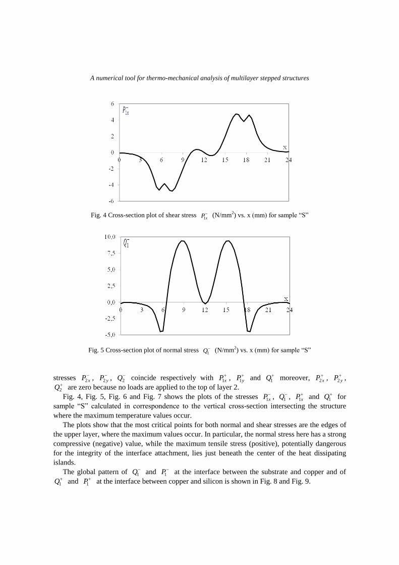
Fig. 4 Cross-section plot of shear stress
xP1 (N/mm
2) vs. x (mm) for sample “S”
Fig. 5 Cross-section plot of normal stress
1Q (N/mm2) vs. x (mm) for sample “S”
stresses xP2 ,
yP2 , 2Q coincide respectively with
xP1 , yP1 and
1Q moreover, xP2 ,
yP2 , 2Q are zero because no loads are applied to the top of layer 2.
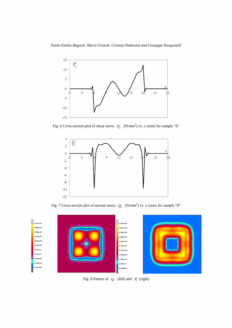
Fig. 4, Fig. 5, Fig. 6 and Fig. 7 shows the plots of the stresses xP1 ,
1Q , xP1 and
1Q for
sample “S” calculated in correspondence to the vertical cross-section intersecting the structure
where the maximum temperature values occur.
The plots show that the most critical points for both normal and shear stresses are the edges of
the upper layer, where the maximum values occur. In particular, the normal stress here has a strong
compressive (negative) value, while the maximum tensile stress (positive), potentially dangerous
for the integrity of the interface attachment, lies just beneath the center of the heat dissipating
islands.
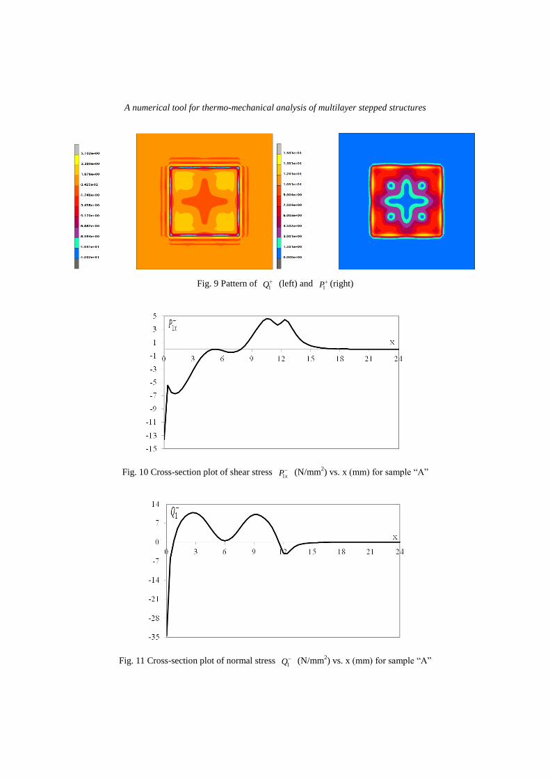
The global pattern of 1Q and
1P at the interface between the substrate and copper and of 1Q and
1P at the interface between copper and silicon is shown in Fig. 8 and Fig. 9.
Paolo Emilio Bagnoli, Maria Girardi, Cristina Padovani and Giuseppe Pasquinelli
Fig. 6 Cross-section plot of shear stress
xP1 (N/mm
2) vs. x (mm) for sample “S”
Fig. 7 Cross-section plot of normal stress
1Q (N/mm2) vs. x (mm) for sample “S”
Fig. 8 Pattern of 1Q (left) and
1P (right)
A numerical tool for thermo-mechanical analysis of multilayer stepped structures
Fig. 9 Pattern of 1Q (left) and
1P (right)
Fig. 10 Cross-section plot of shear stress xP1
(N/mm2) vs. x (mm) for sample “A”
Fig. 11 Cross-section plot of normal stress 1Q (N/mm
2) vs. x (mm) for sample “A”

Paolo Emilio Bagnoli, Maria Girardi, Cristina Padovani and Giuseppe Pasquinelli
Fig. 12 Cross-section plot of shear stress xP1 (N/mm
2) vs. x (mm) for sample “A”
Fig. 13 Cross-section plot of normal stress
1Q (N/mm2) vs. x (mm) for sample “A”
Fig. 10, Fig. 11, Fig. 12 and Fig. 13 show the plots of the stresses xP1 ,
1Q , xP1 and
1Q for
sample “A” calculated in correspondence to the vertical cross-section intersecting the structure
where the maximum temperature values occur.
Finally, by comparing the results for samples “S” and “A”, the effect of the structural
asymmetry is quite evident. In fact, in sample “A”, the values of the normal and shear stresses
reached at the copper-heat sink interface are greater than those in sample “S” (see xP1 and
1Q in
Fig. 4 and Fig. 5). On the other hand, the values of the normal and shear stresses at the copper-
silicon interface are similar in both “A” and “S”, even if the maximum values are reached at
different points.
The validation procedure is performed via thermo-mechanical analysis of the “K” series, and
comparing the results with those obtained through standard finite element analysis by discretizing
the structure with a very large number (30720) of 20-node brick elements. Fig. 14 shows the finite
element mesh of the structure, the discretizion of the layers is 64×64×6 elements for the copper
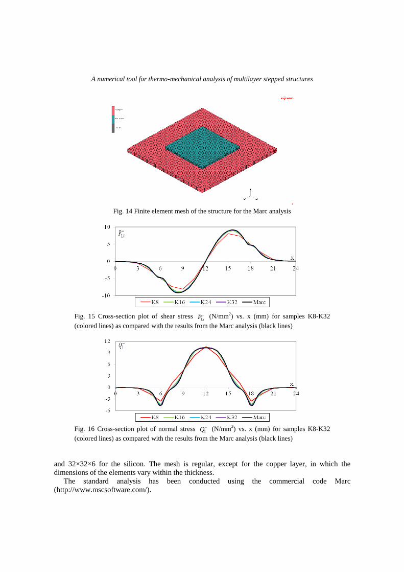
A numerical tool for thermo-mechanical analysis of multilayer stepped structures
Fig. 14 Finite element mesh of the structure for the Marc analysis
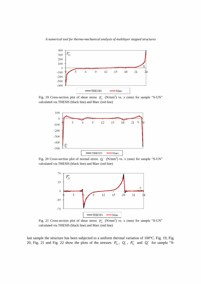
Fig. 15 Cross-section plot of shear stress xP1
(N/mm2) vs. x (mm) for samples K8-K32
(colored lines) as compared with the results from the Marc analysis (black lines)
Fig. 16 Cross-section plot of normal stress 1Q (N/mm
2) vs. x (mm) for samples K8-K32
(colored lines) as compared with the results from the Marc analysis (black lines)
and 32×32×6 for the silicon. The mesh is regular, except for the copper layer, in which the
dimensions of the elements vary within the thickness.
The standard analysis has been conducted using the commercial code Marc
(http://www.mscsoftware.com/).

Paolo Emilio Bagnoli, Maria Girardi, Cristina Padovani and Giuseppe Pasquinelli
Fig. 17 Cross-section plot of shear stress xP1
(N/mm2) vs. x (mm) for samples K8-K32
(colored lines) as compared with the results from the Marc analysis (black lines)
Fig. 18 Cross-section plot of normal stress 1Q (N/mm
2) vs. x (mm) for samples K8-K32
(colored lines) as compared with the results from the Marc analysis (black lines)
Table II
SAMPLE Cells per side (silicon) Time (sec)
K8 8 23.3
K16 16 487.2
K24 24 2541.1
K32 32 8249.6
Marc 74185.9
The aim of the numerical tests is to investigate the dependence of the results on the cell density,
and evaluate computation times. The results of these tests are presented in Fig. 15, Fig. 16, Fig. 17
and Fig. 18, which show the plots of stresses xP1 ,
1Q , xP1 and
1Q corresponding to 8, 16, 24
and 32 cells per side (red, green, light blue and purple lines, respectively) and to the Marc finite
element analysis (black line).
The figures show that the most critical points are the edges of the silicon layer, where the
accuracy of the results depends heavily on the mesh refinement. On the other hand, the
computation time required for the analysis increases with cell density, as reported in Table II,
though it still remains well below the time needed for a Marc run with 30720 brick elements.
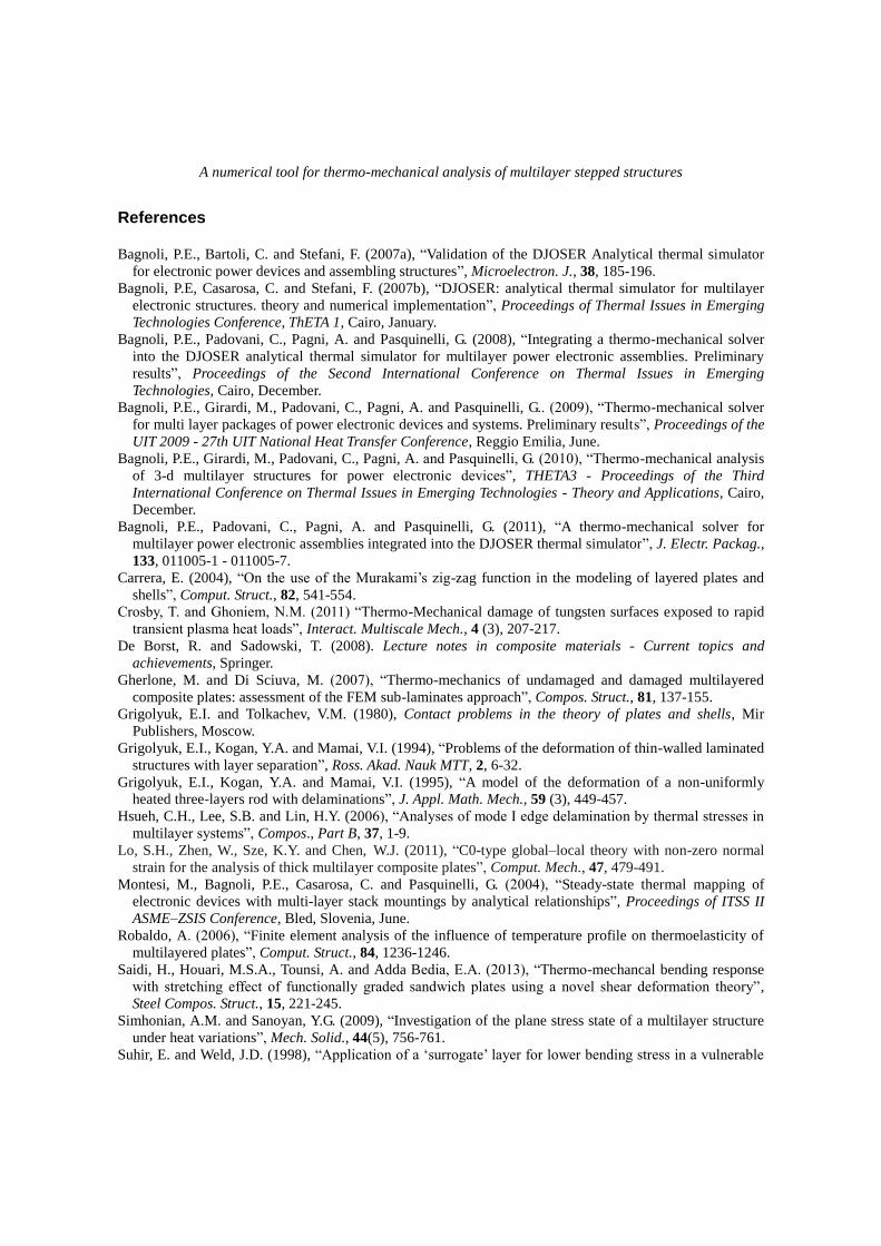
Finally, the results of the analysis performed on the “S-UN” sample is reported below. In this
A numerical tool for thermo-mechanical analysis of multilayer stepped structures
Fig. 19 Cross-section plot of shear stress xP1
(N/mm2) vs. x (mm) for sample “S-UN”
calculated via THESIS (black line) and Marc (red line)
Fig. 20 Cross-section plot of normal stress 1Q (N/mm
2) vs. x (mm) for sample “S-UN”
calculated via THESIS (black line) and Marc (red line)
Fig. 21 Cross-section plot of shear stress xP1
(N/mm2) vs. x (mm) for sample “S-UN”
calculated via THESIS (black line) and Marc (red line)
last sample the structure has been subjected to a uniform thermal variation of 100°C. Fig. 19, Fig.
20, Fig. 21 and Fig. 22 show the plots of the stresses xP1 ,
1Q , xP1 and
1Q for sample “S-

Paolo Emilio Bagnoli, Maria Girardi, Cristina Padovani and Giuseppe Pasquinelli
Fig. 22 Cross-section plot of normal stress 1Q (N/mm
2) vs. x (mm) for sample “S-UN”
calculated via THESIS (black line) and Marc (red line)
UN”, calculated in the middle cross-section, vs. x. As can be seen, once again in this case, the
stresses reach high values, especially at the boundaries of both the layers and the results of the
Marc analysis substantially match those obtained with THESIS.
4. Conclusions
In this paper a numerical mathematical tool for the thermo-mechanical analysis of power
electronic devices and their assemblies has been presented. The aim of the tool is simply to equip
the recently proposed, user-friendly, analytical thermal simulator DJOSER with a suitable
mechanical solver, called THESIS, so that the resulting temperature maps may also be used to
calculate the thermally induced mechanical stresses and strains. The advantages of this simulation
strategy concern both calculation times and the possibility of using uniform rectangular meshes
within the body layers based on the 2-D meshes used by DJOSER for the temperature mapping.
Due to the extreme complexity of a fully analytical solution to the mechanical problem, the
mechanical solver was developed following a finite element strategy, though making use of a new,
expressly developed THESIS element, as described in detail in Subsection 2.2.
The validation tests performed on the samples illustrated in Fig. 3 were carried out by
comparing the THESIS results with those obtained via standard finite element analysis performed
with the commercial code Marc and twenty-nodes brick elements. As expected, this comparison
clearly shows that the accuracy of results depends on the cell density, with the error being highest
near the borders, where the Marc code also presents singularity points and consequently undergoes
a fall in accuracy. Thus, in order to obtain accurate results on the whole structure, it is
recommended that the number of cells utilized not be less than a certain limit, also in light of the
fact that THESIS computational times nevertheless remain considerably lower than Marc ones.
Therefore, thanks to its user-friendliness and the ease of model building, which provides a high
degree of automatization, the coupled DJOSER-THESIS simulation system for thermo-mechanical
analyses of packaged power electronic devices may be a suitable substitute for the more expensive
numerical tools currently in use in small- and medium-sized enterprises involved in electronic
device manufacturing.
A numerical tool for thermo-mechanical analysis of multilayer stepped structures
References Bagnoli, P.E., Bartoli, C. and Stefani, F. (2007a), “Validation of the DJOSER Analytical thermal simulator
for electronic power devices and assembling structures”, Microelectron. J., 38, 185-196.
Bagnoli, P.E, Casarosa, C. and Stefani, F. (2007b), “DJOSER: analytical thermal simulator for multilayer
electronic structures. theory and numerical implementation”, Proceedings of Thermal Issues in Emerging
Technologies Conference, ThETA 1, Cairo, January.
Bagnoli, P.E., Padovani, C., Pagni, A. and Pasquinelli, G. (2008), “Integrating a thermo-mechanical solver
into the DJOSER analytical thermal simulator for multilayer power electronic assemblies. Preliminary
results”, Proceedings of the Second International Conference on Thermal Issues in Emerging
Technologies, Cairo, December.
Bagnoli, P.E., Girardi, M., Padovani, C., Pagni, A. and Pasquinelli, G.. (2009), “Thermo-mechanical solver
for multi layer packages of power electronic devices and systems. Preliminary results”, Proceedings of the
UIT 2009 - 27th UIT National Heat Transfer Conference, Reggio Emilia, June.
Bagnoli, P.E., Girardi, M., Padovani, C., Pagni, A. and Pasquinelli, G. (2010), “Thermo-mechanical analysis
of 3-d multilayer structures for power electronic devices”, THETA3 - Proceedings of the Third
International Conference on Thermal Issues in Emerging Technologies - Theory and Applications, Cairo,
December.
Bagnoli, P.E., Padovani, C., Pagni, A. and Pasquinelli, G. (2011), “A thermo-mechanical solver for
multilayer power electronic assemblies integrated into the DJOSER thermal simulator”, J. Electr. Packag.,
133, 011005-1 - 011005-7.
Carrera, E. (2004), “On the use of the Murakami‟s zig-zag function in the modeling of layered plates and
shells”, Comput. Struct., 82, 541-554.
Crosby, T. and Ghoniem, N.M. (2011) “Thermo-Mechanical damage of tungsten surfaces exposed to rapid
transient plasma heat loads”, Interact. Multiscale Mech., 4 (3), 207-217.
De Borst, R. and Sadowski, T. (2008). Lecture notes in composite materials - Current topics and
achievements, Springer.
Gherlone, M. and Di Sciuva, M. (2007), “Thermo-mechanics of undamaged and damaged multilayered
composite plates: assessment of the FEM sub-laminates approach”, Compos. Struct., 81, 137-155.
Grigolyuk, E.I. and Tolkachev, V.M. (1980), Contact problems in the theory of plates and shells, Mir
Publishers, Moscow.
Grigolyuk, E.I., Kogan, Y.A. and Mamai, V.I. (1994), “Problems of the deformation of thin-walled laminated
structures with layer separation”, Ross. Akad. Nauk MTT, 2, 6-32.
Grigolyuk, E.I., Kogan, Y.A. and Mamai, V.I. (1995), “A model of the deformation of a non-uniformly
heated three-layers rod with delaminations”, J. Appl. Math. Mech., 59 (3), 449-457.
Hsueh, C.H., Lee, S.B. and Lin, H.Y. (2006), “Analyses of mode I edge delamination by thermal stresses in
multilayer systems”, Compos., Part B, 37, 1-9.
Lo, S.H., Zhen, W., Sze, K.Y. and Chen, W.J. (2011), “C0-type global–local theory with non-zero normal
strain for the analysis of thick multilayer composite plates”, Comput. Mech., 47, 479-491.
Montesi, M., Bagnoli, P.E., Casarosa, C. and Pasquinelli, G. (2004), “Steady-state thermal mapping of
electronic devices with multi-layer stack mountings by analytical relationships”, Proceedings of ITSS II
ASME–ZSIS Conference, Bled, Slovenia, June.
Robaldo, A. (2006), “Finite element analysis of the influence of temperature profile on thermoelasticity of
multilayered plates”, Comput. Struct., 84, 1236-1246.
Saidi, H., Houari, M.S.A., Tounsi, A. and Adda Bedia, E.A. (2013), “Thermo-mechancal bending response
with stretching effect of functionally graded sandwich plates using a novel shear deformation theory”,
Steel Compos. Struct., 15, 221-245.
Simhonian, A.M. and Sanoyan, Y.G. (2009), “Investigation of the plane stress state of a multilayer structure
under heat variations”, Mech. Solid., 44(5), 756-761.
Suhir, E. and Weld, J.D. (1998), “Application of a „surrogate‟ layer for lower bending stress in a vulnerable
Paolo Emilio Bagnoli, Maria Girardi, Cristina Padovani and Giuseppe Pasquinelli
material of a tri-material body”, Microelectron. Reliab., 38, 1949-1954.
Suhir, E. (2000), “Adhesively bonded assemblies with identical nondeformable adherends and „piecewise
continuous‟ adhesive layer: predicted thermal stresses in the adhesive”, Int. J. Solid. Struct., 37, 2229-
2252.
Suhir, E. (2011), “Predictes stresses in die-carrier assemblies in “stretchable” electronics: is there an
incentive for using a compliant bond”, ZAMM Z. Angew. Math. Mech., 91(1), 57-67.
Timoshenko, S.P. and Woinowsky-Krieger, S. (1959), Theory of plates and shells, McGraw-Hill Internatioal
Editions.
Wu, L.Z. (2004), “Thermoelastic analysis of chip-substrate system”, J. Electron. Packag., 126, 326-332.
Xie, W.D. and Sitaraman, S.K. (2000), “Interfacial thermal stress analysis of anisotropic multi-layered
eletronic packaging structures”, J. Electron. Packag., 122, 66-68.
Zhen, W. and Chen, W.J. (2007), “A quadrilateral element based on refined global-local higher-order theory
for coupling bending and extension thermo-elastic multilayered plates”, Int. J. Solid. Struct., 44, 3187-
3217.
Zienkiewicz, O.C. and Taylor, R.L. (1989), The Finite Element Method, Basic formulation and linear
problems, Fourth Edition, Volume 1, McGraw-Hill, London, UK.