A novel autonomous low-cost on-board data handling architecture for a pin-point planetary lander
19
A novel autonomous low-cost on-board data handling architecture for a pin-point planetary lander Tanya Vladimirova a,n , Muhammad Fayyaz a , Martin N. Sweeting a , Valentin I. Vitanov b a Surrey Space Centre, Department of Electronic Engineering, University of Surrey, Guildford GU2 7XH, UK b School of Engineering and Computer Sciences, Durham University, South Road, Durham DH1 3LE, UK article info Article history: Received 2 May 2009 Received in revised form 14 June 2010 Accepted 24 August 2010 Available online 12 October 2010 Keywords: On-board data handling Pin-point planetary lander Field programmable gate array abstract There has been increased interest in the exploration of the Moon in recent years. Pin- point precision landing is highly desirable for future lunar missions. This paper is concerned with the design of the on-board data handling (OBDH) subsystem for the pin- point lunar lander of the Magnolia-1 project, funded by NASA. Four proposed on-board data handling architectures are outlined and compared in terms of power consumption, performance and reliability. Implementation results are presented, which are obtained from prototyping of the flight computer for the optimal OBDH architecture option on a Xilinx Virtex-5 Field Programmable Gate Array. & 2010 Elsevier Ltd. All rights reserved. 1. Introduction Recently, there has been increased interest in the exploration of the Moon. Pin-point precision landing is highly desirable for scientific exploration and future manned missions to the Moon. NASA’s concerted effort on precision lunar landing started in 2006 as part of the Autonomous precision Landing Hazard Avoidance Technol- ogy (ALHAT) project. The aim was to develop a lunar descent and landing guidance and navigation control (GNC) system capable of supporting lunar crewed, cargo and robotic missions [1]. Also in 2006, the UK Particle Physics and Astronomy Research Council (PPARC) funded a con- sortium, including Surrey Satellite Technology Limited (SSTL) and Surrey Space Centre, to carry out a study for a UK-led low-cost small scale lunar mission. As a conse- quence of this study, two missions were proposed, named MoonLite and MoonRaker. The MoonLite mission aimed to deploy penetrators from an orbiter onto the lunar surface while the MoonRaker mission aimed to provide a low-cost precision landing capability for robotic exploration of the Moon [2]. This was followed by a research project, funded by NASA, the aim of which was to define the subsystems requirements for the MoonRaker precision lander. The project, named Magnolia-1, was carried out by the Surrey Space Centre in collaboration with Mississippi State University. This paper reports on the preliminary design effort related to the on-board data handling (OBDH) subsystem for the pin-point precision lander of the Magnolia-1 project. The heart of any OBDH subsystem is the main on-board computer (OBC), referred to as spacecraft flight computer in this paper. Previously, OBDH subsystems had limited functionality and specialised tasks, e.g. spacecraft attitude determination and orbit control (ADOC), were performed by separate controllers and not by the flight computer. This was due to the insufficient processing power of earlier OBCs. With the migration of advanced processor technol- ogies on board, OBDH subsystems nowadays are not limited to data handling only, but are also capable of performing a wide range of data processing and control tasks, including ADOC, scheduling, planning, etc. The spacecraft flight computer has traditionally been realised in the form of a printed circuit board design (PCB), centred Contents lists available at ScienceDirect journal homepage: www.elsevier.com/locate/actaastro Acta Astronautica 0094-5765/$ - see front matter & 2010 Elsevier Ltd. All rights reserved. doi:10.1016/j.actaastro.2010.08.029 n Corresponding author. Tel.: + 44 1483 689137. E-mail address: [email protected] (T. Vladimirova). Acta Astronautica 68 (2011) 811–829
Transcript of A novel autonomous low-cost on-board data handling architecture for a pin-point planetary lander
Contents lists available at ScienceDirect
Acta Astronautica
Acta Astronautica 68 (2011) 811–829
0094-57
doi:10.1
n Corr
E-m
journal homepage: www.elsevier.com/locate/actaastro
A novel autonomous low-cost on-board data handling architecturefor a pin-point planetary lander
Tanya Vladimirova a,n, Muhammad Fayyaz a, Martin N. Sweeting a, Valentin I. Vitanov b
a Surrey Space Centre, Department of Electronic Engineering, University of Surrey, Guildford GU2 7XH, UKb School of Engineering and Computer Sciences, Durham University, South Road, Durham DH1 3LE, UK
a r t i c l e i n f o
Article history:
Received 2 May 2009
Received in revised form
14 June 2010
Accepted 24 August 2010Available online 12 October 2010
Keywords:
On-board data handling
Pin-point planetary lander
Field programmable gate array
65/$ - see front matter & 2010 Elsevier Ltd. A
016/j.actaastro.2010.08.029
esponding author. Tel.: +44 1483 689137.
ail address: [email protected] (T. Vl
a b s t r a c t
There has been increased interest in the exploration of the Moon in recent years. Pin-
point precision landing is highly desirable for future lunar missions. This paper is
concerned with the design of the on-board data handling (OBDH) subsystem for the pin-
point lunar lander of the Magnolia-1 project, funded by NASA. Four proposed on-board
data handling architectures are outlined and compared in terms of power consumption,
performance and reliability. Implementation results are presented, which are obtained
from prototyping of the flight computer for the optimal OBDH architecture option on a
Xilinx Virtex-5 Field Programmable Gate Array.
& 2010 Elsevier Ltd. All rights reserved.
1. Introduction
Recently, there has been increased interest in theexploration of the Moon. Pin-point precision landing ishighly desirable for scientific exploration and futuremanned missions to the Moon. NASA’s concerted efforton precision lunar landing started in 2006 as part of theAutonomous precision Landing Hazard Avoidance Technol-ogy (ALHAT) project. The aim was to develop a lunardescent and landing guidance and navigation control (GNC)system capable of supporting lunar crewed, cargo androbotic missions [1]. Also in 2006, the UK Particle Physicsand Astronomy Research Council (PPARC) funded a con-sortium, including Surrey Satellite Technology Limited(SSTL) and Surrey Space Centre, to carry out a study for aUK-led low-cost small scale lunar mission. As a conse-quence of this study, two missions were proposed, namedMoonLite and MoonRaker. The MoonLite mission aimed todeploy penetrators from an orbiter onto the lunar surfacewhile the MoonRaker mission aimed to provide a low-cost
ll rights reserved.
adimirova).
precision landing capability for robotic exploration of theMoon [2]. This was followed by a research project, fundedby NASA, the aim of which was to define the subsystemsrequirements for the MoonRaker precision lander. Theproject, named Magnolia-1, was carried out by the SurreySpace Centre in collaboration with Mississippi StateUniversity. This paper reports on the preliminary designeffort related to the on-board data handling (OBDH)subsystem for the pin-point precision lander of theMagnolia-1 project.
The heart of any OBDH subsystem is the main on-boardcomputer (OBC), referred to as spacecraft flight computerin this paper. Previously, OBDH subsystems had limitedfunctionality and specialised tasks, e.g. spacecraft attitudedetermination and orbit control (ADOC), were performedby separate controllers and not by the flight computer.This was due to the insufficient processing power of earlierOBCs. With the migration of advanced processor technol-ogies on board, OBDH subsystems nowadays are notlimited to data handling only, but are also capable ofperforming a wide range of data processing and controltasks, including ADOC, scheduling, planning, etc. Thespacecraft flight computer has traditionally been realisedin the form of a printed circuit board design (PCB), centred
T. Vladimirova et al. / Acta Astronautica 68 (2011) 811–829812
around a commercial microcontroller [3], however atpresent it is possible to be designed as a complete systemon a single chip [4].
The purpose of pin-point landing is to safely land onthe surface of a planet within a defined limited range. Theon-board data handling subsystem plays a crucial role inpin-point precision lunar landing, which has a very shortdescent phase (�300 s). Light detection and ranging(LIDAR) and optical camera sensors can be used for thepin-point landing navigation and targeting. The sensordata are processed by on-board processors using auton-omous hazard avoidance and detection algorithms, whichrequire substantial computer resources in terms ofmemory and throughput. In addition, pin-point landingimposes a very strong requirement with regards to thereliability of the OBDH subsystem. The OBDH should beable to recover immediately from a single-point failure inany part of the system during the extremely shortduration of the descent phase. Data transportationbetween OBDH and different subsystems on-board thelander needs to be designed carefully to minimize thelatency and power consumption in any part of the design.There are a number of data interfaces that are usedon-board such as the standard serial data buses MIL-STD-1553, Controller Area Network (CAN), SpaceWire, Fire-Wire, etc., however the existing solutions have to beevaluated to select the best option in terms of low powerand high speed.
This paper is structured as follows. Section 2 sum-marizes OBDH subsystems of existing and proposedplanetary landers. Requirement specification and con-straints for the Magnolia-1 pin-point planetary landerOBDH subsystem are outlined in Section 3. Section 4describes and compares four proposed on-board datahandling architectures. Section 5 presents prototypingresults and Section 6 concludes the paper.
2. Background
This section reviews on-board data handling subsys-tems of existing and planned planetary lander missions.
US and Russia carried out a number of Moon landingsfrom the mid-1960s to the mid-1970s. The Russian Luna 9mission was the first spacecraft to achieve a soft lunarlanding and to transmit photographic data from the Moon’ssurface to Earth on February 3, 1966. Humans first landedon the Moon on July 20, 1969 as part of the NASA Apolloprogram. The Russian Luna 17 lander delivered the firstlunar rover Lunokhod 1 (Moonwalker 1) on the Moon onNovember 17, 1970. However, apart of the Apollo missions,no details about the OBDH subsystems of these lunarlanders were found in the open literature. The mainobjective of the Apollo missions was to land men on theMoon and return them safely. The on-board data handlingarchitecture for the Apollo mission was centralized aroundone computer, called lander Guidance Computer (LGC),which provided general purpose computing as well ascontrol functionality. However, some support circuitry forthe Attitude & Orbit Control (AOC) and optical payload wereincluded in the coupling data unit, optical, inertial and
signal conditioning subsections [5]. Computer hot redun-dancy was not provided on the Apollo mission apart ofmanual fail-safe operation and the computer systemthroughput was very low.
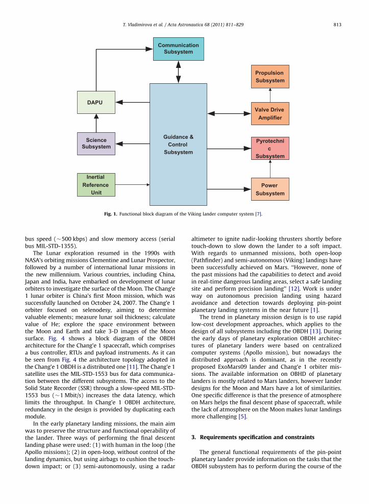
The US Mars exploration project Viking, initiated in1968, resulted in the launch of two identical spacecraftViking 1 and Viking 2, each consisting of a lander and anorbiter. Launched on August 20 and September 9, 1975Viking 1 and Viking 2 landed on Mars on July 20, andSeptember 3, 1976, respectively [6]. The main purpose ofthe Viking missions was to increase the understanding ofthe planet Mars through orbital observations or directmeasurements by the landers during the entry, descentand landing (EDL) phase. Fig. 1 shows the block diagram ofthe Viking lander computer system. It adopts a centralizedapproach and consists of two parts: a guidance & controlsubsystem and a Data Acquisition & Processing unit(DAPU). The guidance & control part is the core of thecomputer system and is responsible for generatingcommands and data for the rest of the subsystem. DAPUperforms science and engineering telemetry data acquisi-tion from all subsystems and passes telemetry data to thecommunication subsystem up on a request from theguidance & control computer [7]. Important finding fromstudying the Viking OBDH subsystem is the fact that thecomplete control loop takes 20 ms, which can be used as areference point for the design of the pin-point landercomputer system.
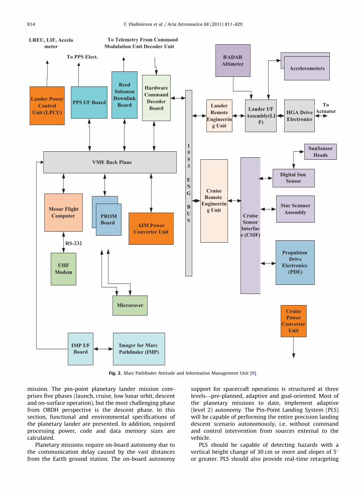
Mars Pathfinder was the first completed mission inNASA’s Discovery Program of low-cost, rapidly developedplanetary missions with highly focused science goals. Itlanded on July 4, 1997 [8]. The purpose of the Pathfindermission was to analyze the climate, atmosphere, geologyand rock-soil composition of the red planet. The MarsPathfinder spacecraft was a single propulsive soft lander,which carried the Sojourner robotic rover. The MarsPathfinder OBDH comprises one centralized unit, calledAttitude and Information Management (AIM) unit (Fig. 2),and all the other units are connected to the centralizedunit through the MIL-STD-1553 bus and the VERSAModule Eurocard (VME) bus [9]. A hybrid solution isselected for the data transportation – the VME bus is usedfor high speed data transfers and the MIL-STD-1553 bus –for low-speed data transfers. Although, the Mars Pathfin-der adopts a dual bus architecture, a single-point of failureof the RSC6000 radiation hardened processor could causea complete mission failure.
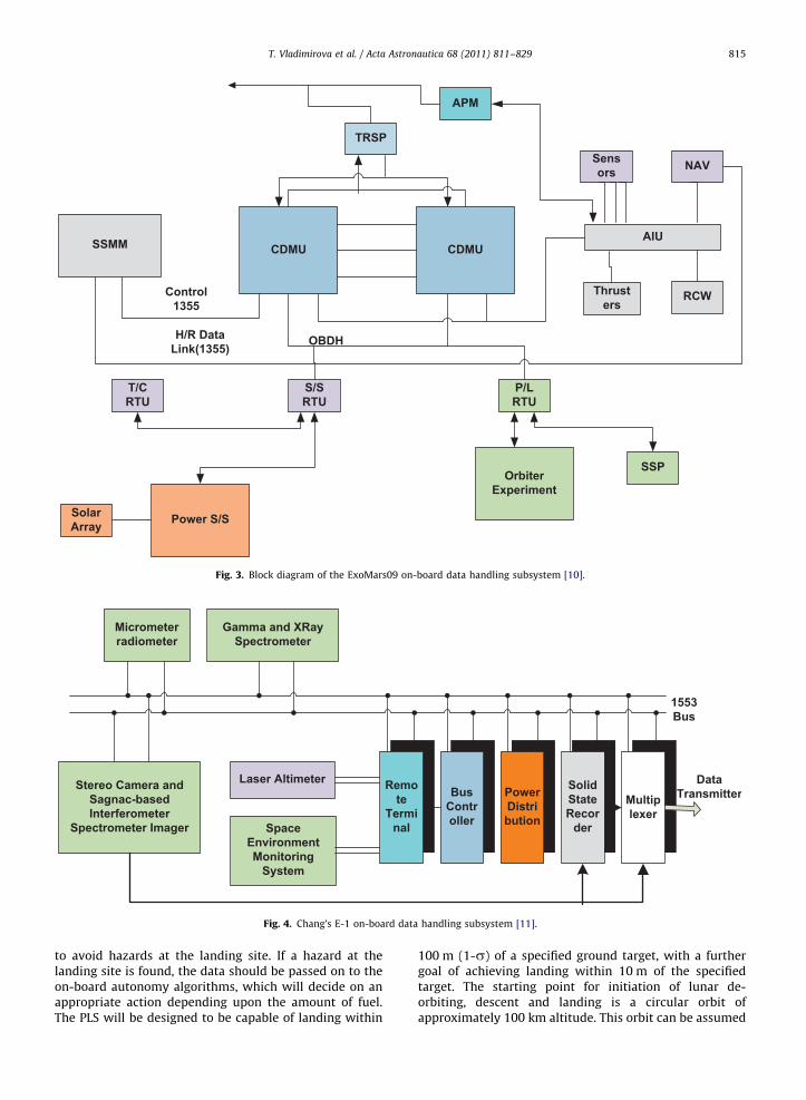
The purpose of the planned European-led ExoMars(Exobiology on Mars) mission, currently under develop-ment by the European Space Agency (ESA) and NASA, is tosearch for past and present sign of life on the red planet.The ExoMars09 mission adopts a distributed approachand its OBDH system comprises two Control & DataManagement Units (CDMUs), Payload Remote TerminalUnits (RTUs), engineering data RTUs and an AttitudeInformation Unit (AIU) as shown in Fig. 3. AIU isconnected directly to CDMU and RTUs are connectedthrough the European Space Agency OBDH bus [10]. Theredundancy technique adopted in the ExoMars09 designprovides fail-safe operation against failure, however it isnot suitable for pin-point landing due to the low OBDH
Guidance &Control
Subsystem
Valve Drive Amplifier
ScienceSubsystem
Pyrotechnic
Subsystem
Power Subsystem
CommunicationSubsystem
DAPU
Propulsion Subsystem
Inertial Reference
Unit
Fig. 1. Functional block diagram of the Viking lander computer system [7].
T. Vladimirova et al. / Acta Astronautica 68 (2011) 811–829 813
bus speed (�500 kbps) and slow memory access (serialbus MIL-STD-1355).
The Lunar exploration resumed in the 1990s withNASA’s orbiting missions Clementine and Lunar Prospector,followed by a number of international lunar missions inthe new millennium. Various countries, including China,Japan and India, have embarked on development of lunarorbiters to investigate the surface of the Moon. The Chang’e1 lunar orbiter is China’s first Moon mission, which wassuccessfully launched on October 24, 2007. The Chang’e 1orbiter focused on selenodesy, aiming to determinevaluable elements; measure lunar soil thickness; calculatevalue of He; explore the space environment betweenthe Moon and Earth and take 3-D images of the Moonsurface. Fig. 4 shows a block diagram of the OBDHarchitecture for the Chang’e 1 spacecraft, which comprisesa bus controller, RTUs and payload instruments. As it canbe seen from Fig. 4 the architecture topology adopted inthe Chang’e 1 OBDH is a distributed one [11]. The Chang’e 1satellite uses the MIL-STD-1553 bus for data communica-tion between the different subsystems. The access to theSolid State Recorder (SSR) through a slow-speed MIL-STD-1553 bus (�1 Mbit/s) increases the data latency, whichlimits the throughput. In Chang’e 1 OBDH architecture,redundancy in the design is provided by duplicating eachmodule.
In the early planetary landing missions, the main aimwas to preserve the structure and functional operability ofthe lander. Three ways of performing the final descentlanding phase were used: (1) with human in the loop (theApollo missions); (2) in open-loop, without control of thelanding dynamics, but using airbags to cushion the touch-down impact; or (3) semi-autonomously, using a radar
altimeter to ignite nadir-looking thrusters shortly beforetouch-down to slow down the lander to a soft impact.With regards to unmanned missions, both open-loop(Pathfinder) and semi-autonomous (Viking) landings havebeen successfully achieved on Mars. ‘‘However, none ofthe past missions had the capabilities to detect and avoidin real-time dangerous landing areas, select a safe landingsite and perform precision landing’’ [12]. Work is underway on autonomous precision landing using hazardavoidance and detection towards deploying pin-pointplanetary landing systems in the near future [1].
The trend in planetary mission design is to use rapidlow-cost development approaches, which applies to thedesign of all subsystems including the OBDH [13]. Duringthe early days of planetary exploration OBDH architec-tures of planetary landers were based on centralizedcomputer systems (Apollo mission), but nowadays thedistributed approach is dominant, as in the recentlyproposed ExoMars09 lander and Chang’e 1 orbiter mis-sions. The available information on OBHD of planetarylanders is mostly related to Mars landers, however landerdesigns for the Moon and Mars have a lot of similarities.One specific difference is that the presence of atmosphereon Mars helps the final descent phase of spacecraft, whilethe lack of atmosphere on the Moon makes lunar landingsmore challenging [5].
3. Requirements specification and constraints
The general functional requirements of the pin-pointplanetary lander provide information on the tasks that theOBDH subsystem has to perform during the course of the
VME Back Plane
1553
ENG
BUS
HardwareCommandDecoderBoard
ReedSolomonDownlink
BoardPPS I/F Board
PROMBoard AIM Power
Converter Unit
Mesur FlightComputer
Lander PowerControl
Unit (LPCU)LanderRemote
Engineering Unit
CruiseRemote
Engineering Unit
CruiseSensor
Interface (CSIF)
Digital Sun Sensor
Star ScannerAssembly
Propulsion Drive
Electronics (PDE)
SunSensorHeads
CruisePower
ConverterUnit
UHFModem
Microrover
IMP I/FBoard
Imager for MarsPathfinder (IMP)
Lander I/FAssembly(LI
F)
HGA DriveElectronics
LREU, LIF, Accelometer
To PPS Elect.
To Telemetry From CommandModulation Unit Decoder Unit
ToActuator
Accelerometers
RS-232
RADARAltimeter
Fig. 2. Mars Pathfinder Attitude and Information Management Unit [9].
T. Vladimirova et al. / Acta Astronautica 68 (2011) 811–829814
mission. The pin-point planetary lander mission com-prises five phases (launch, cruise, low lunar orbit, descentand on-surface operation), but the most challenging phasefrom OBDH perspective is the descent phase. In thissection, functional and environmental specifications ofthe planetary lander are presented. In addition, requiredprocessing power, code and data memory sizes arecalculated.
Planetary missions require on-board autonomy due tothe communication delay caused by the vast distancesfrom the Earth ground station. The on-board autonomy
support for spacecraft operations is structured at threelevels—pre-planned, adaptive and goal-oriented. Most ofthe planetary missions to date, implement adaptive(level 2) autonomy. The Pin-Point Landing System (PLS)will be capable of performing the entire precision landingdescent scenario autonomously, i.e. without commandand control intervention from sources external to thevehicle.
PLS should be capable of detecting hazards with avertical height change of 30 cm or more and slopes of 51or greater. PLS should also provide real-time retargeting
CDMU CDMUSSMM AIU
Sensors NAV
Thrusters
RCW
TRSP
APM
SSPOrbiter
Experiment
T/CRTU
S/SRTU
P/LRTU
Power S/SSolarArray
Control1355
H/R DataLink(1355)
OBDH
Fig. 3. Block diagram of the ExoMars09 on-board data handling subsystem [10].
SolidStateRecor
der
Remote
Terminal
BusController
PowerDistribution
Multiplexer
Gamma and XRaySpectrometer
Micrometerradiometer
Stereo Camera andSagnac-basedInterferometer
Spectrometer Imager
Laser Altimeter
SpaceEnvironmentMonitoring
System
DataTransmitter
1553Bus
Fig. 4. Chang’s E-1 on-board data handling subsystem [11].
T. Vladimirova et al. / Acta Astronautica 68 (2011) 811–829 815
to avoid hazards at the landing site. If a hazard at thelanding site is found, the data should be passed on to theon-board autonomy algorithms, which will decide on anappropriate action depending upon the amount of fuel.The PLS will be designed to be capable of landing within
100 m (1-s) of a specified ground target, with a furthergoal of achieving landing within 10 m of the specifiedtarget. The starting point for initiation of lunar de-orbiting, descent and landing is a circular orbit ofapproximately 100 km altitude. This orbit can be assumed
T. Vladimirova et al. / Acta Astronautica 68 (2011) 811–829816
to be appropriately oriented to overfly the landing siteregion with enough accuracy so that the landing site isreachable by the vehicle. The standard (non-PLS) naviga-tion system will be capable of determining its positionwithin the 100 km lunar orbit to 1 km accuracy and its3-axis attitude to 11 in each axis [14]. It is required thatthe PLS landing be planned only for time periods thatguarantee appropriate lighting for the function of thevision-based navigation and guidance sensors.
At the start of the on-surface operation phase the PLSon-board computer will support a series of deploymenttasks such as solar panel deployment, antenna deploy-ment, magnetometer boom and stereo imager deploy-ment, rover and robotic manipulator deployment, etc. It isassumed that the lander will communicate with a lunarorbiter, although direct communication with an Earthground station is also possible subject to power budgetand transmitter capabilities. Communication with a free-ranging robotic rover will also be maintained for thepurpose of sending commands and acquisition of experi-mental data.
The Moon planetary environment affects the on-boarddata handling electronics, as it is not as benign as that onEarth. The environmental components, which should betaken care of, are gravity field, topography, surfaceenvironment, thermal environment, radiation environmentand micrometeorite environment. The lunar gravity fieldneeds to be accounted for during the planning of orbitalmaneuvers, descent and landing, however risk due togravity is medium and position and velocity errors aresmall due to the non-uniform nature of the field. The lunartopography poses a significant risk to the pin-pointplanetary lander because of the extreme elevation, curva-ture and cratered high land. The Moon has no significantsurface atmosphere but has a small amount of tiny gas andatmospheric pressure equal to 10�12. The temperaturevariation on the Moon is extremely challenging because ofthe abrupt change from day temperature of +120 1C tonight temperature of �150 1C, so components should be
Table 1Communication subsystem processing power and memory.
Task Throughput Code memory
(Kwords)
Command processing 7.0 KIPS 10
Data processing 3.0 KIPS 10
Table 2Computing requirements for a traditional navigation & control subsystem.
Task Throughput Code m
(Kword
Kinematics integration 0.3 MIPS 20
Error determination 0.5 MIPS 10
Thrusters control 1.2 KIPS 6
Orbit propagations 0.2 MIPS 130
Complex ephemeris 0.2 MIPS 35
IMU 18.0 KIPS 16
Star camera – 2
selected with a proper temperature range of operation. Themost hazardous effects are caused by radiation as nonatural radiation shielding exists around the Moon, so thelunar surface is directly exposed to galactic and solarradiation. In order to avoid these effects, radiationhardened devices should be used in the critical parts ofthe spacecraft [15].
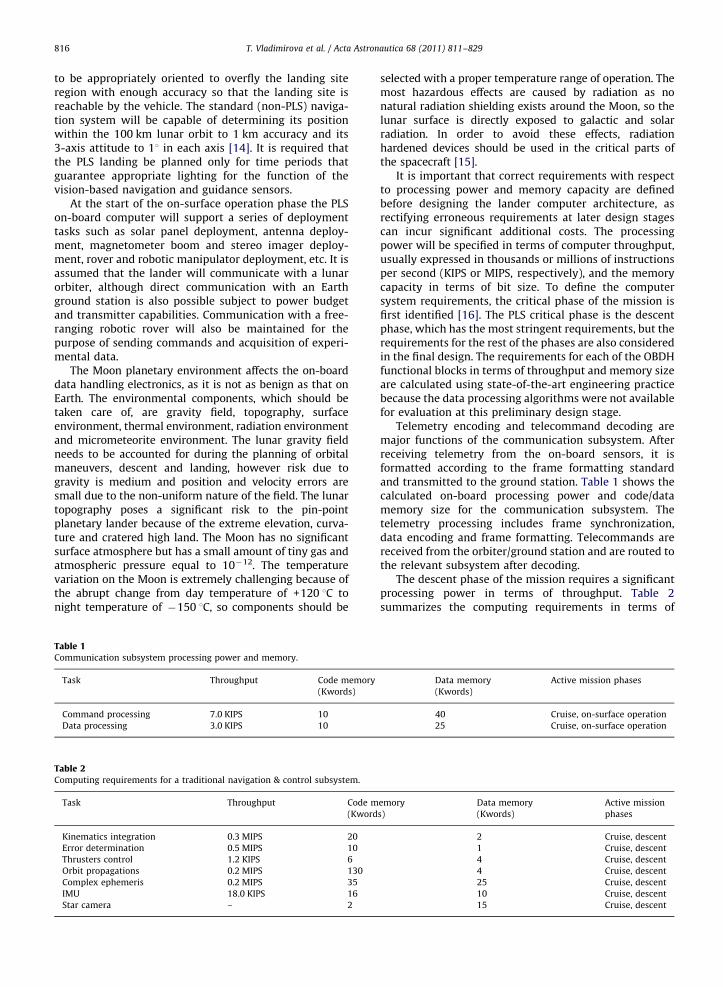
It is important that correct requirements with respectto processing power and memory capacity are definedbefore designing the lander computer architecture, asrectifying erroneous requirements at later design stagescan incur significant additional costs. The processingpower will be specified in terms of computer throughput,usually expressed in thousands or millions of instructionsper second (KIPS or MIPS, respectively), and the memorycapacity in terms of bit size. To define the computersystem requirements, the critical phase of the mission isfirst identified [16]. The PLS critical phase is the descentphase, which has the most stringent requirements, but therequirements for the rest of the phases are also consideredin the final design. The requirements for each of the OBDHfunctional blocks in terms of throughput and memory sizeare calculated using state-of-the-art engineering practicebecause the data processing algorithms were not availablefor evaluation at this preliminary design stage.
Telemetry encoding and telecommand decoding aremajor functions of the communication subsystem. Afterreceiving telemetry from the on-board sensors, it isformatted according to the frame formatting standardand transmitted to the ground station. Table 1 shows thecalculated on-board processing power and code/datamemory size for the communication subsystem. Thetelemetry processing includes frame synchronization,data encoding and frame formatting. Telecommands arereceived from the orbiter/ground station and are routed tothe relevant subsystem after decoding.
The descent phase of the mission requires a significantprocessing power in terms of throughput. Table 2summarizes the computing requirements in terms of
Data memory
(Kwords)
Active mission phases
40 Cruise, on-surface operation
25 Cruise, on-surface operation
emory
s)
Data memory
(Kwords)
Active mission
phases
2 Cruise, descent
1 Cruise, descent
4 Cruise, descent
4 Cruise, descent
25 Cruise, descent
10 Cruise, descent
15 Cruise, descent
T. Vladimirova et al. / Acta Astronautica 68 (2011) 811–829 817
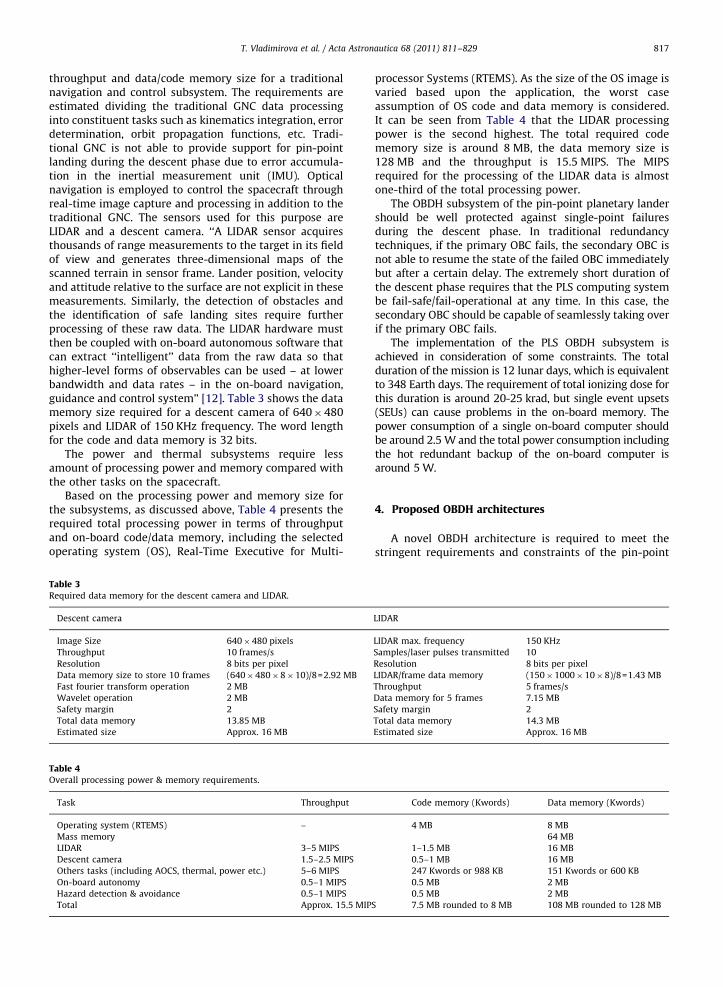
throughput and data/code memory size for a traditionalnavigation and control subsystem. The requirements areestimated dividing the traditional GNC data processinginto constituent tasks such as kinematics integration, errordetermination, orbit propagation functions, etc. Tradi-tional GNC is not able to provide support for pin-pointlanding during the descent phase due to error accumula-tion in the inertial measurement unit (IMU). Opticalnavigation is employed to control the spacecraft throughreal-time image capture and processing in addition to thetraditional GNC. The sensors used for this purpose areLIDAR and a descent camera. ‘‘A LIDAR sensor acquiresthousands of range measurements to the target in its fieldof view and generates three-dimensional maps of thescanned terrain in sensor frame. Lander position, velocityand attitude relative to the surface are not explicit in thesemeasurements. Similarly, the detection of obstacles andthe identification of safe landing sites require furtherprocessing of these raw data. The LIDAR hardware mustthen be coupled with on-board autonomous software thatcan extract ‘‘intelligent’’ data from the raw data so thathigher-level forms of observables can be used – at lowerbandwidth and data rates – in the on-board navigation,guidance and control system’’ [12]. Table 3 shows the datamemory size required for a descent camera of 640�480pixels and LIDAR of 150 KHz frequency. The word lengthfor the code and data memory is 32 bits.
The power and thermal subsystems require lessamount of processing power and memory compared withthe other tasks on the spacecraft.
Based on the processing power and memory size forthe subsystems, as discussed above, Table 4 presents therequired total processing power in terms of throughputand on-board code/data memory, including the selectedoperating system (OS), Real-Time Executive for Multi-
Table 3Required data memory for the descent camera and LIDAR.
Descent camera
Image Size 640�480 pixels
Throughput 10 frames/s
Resolution 8 bits per pixel
Data memory size to store 10 frames (640�480�8�10)/8=2.92 MB
Fast fourier transform operation 2 MB
Wavelet operation 2 MB
Safety margin 2
Total data memory 13.85 MB
Estimated size Approx. 16 MB
Table 4Overall processing power & memory requirements.
Task Throughput
Operating system (RTEMS) –
Mass memory
LIDAR 3–5 MIPS
Descent camera 1.5–2.5 MIPS
Others tasks (including AOCS, thermal, power etc.) 5–6 MIPS
On-board autonomy 0.5–1 MIPS
Hazard detection & avoidance 0.5–1 MIPS
Total Approx. 15.5 MIP
processor Systems (RTEMS). As the size of the OS image isvaried based upon the application, the worst caseassumption of OS code and data memory is considered.It can be seen from Table 4 that the LIDAR processingpower is the second highest. The total required codememory size is around 8 MB, the data memory size is128 MB and the throughput is 15.5 MIPS. The MIPSrequired for the processing of the LIDAR data is almostone-third of the total processing power.
The OBDH subsystem of the pin-point planetary landershould be well protected against single-point failuresduring the descent phase. In traditional redundancytechniques, if the primary OBC fails, the secondary OBC isnot able to resume the state of the failed OBC immediatelybut after a certain delay. The extremely short duration ofthe descent phase requires that the PLS computing systembe fail-safe/fail-operational at any time. In this case, thesecondary OBC should be capable of seamlessly taking overif the primary OBC fails.
The implementation of the PLS OBDH subsystem isachieved in consideration of some constraints. The totalduration of the mission is 12 lunar days, which is equivalentto 348 Earth days. The requirement of total ionizing dose forthis duration is around 20-25 krad, but single event upsets(SEUs) can cause problems in the on-board memory. Thepower consumption of a single on-board computer shouldbe around 2.5 W and the total power consumption includingthe hot redundant backup of the on-board computer isaround 5 W.
4. Proposed OBDH architectures
A novel OBDH architecture is required to meet thestringent requirements and constraints of the pin-point
LIDAR
LIDAR max. frequency 150 KHz
Samples/laser pulses transmitted 10
Resolution 8 bits per pixel
LIDAR/frame data memory (150�1000�10�8)/8=1.43 MB
Throughput 5 frames/s
Data memory for 5 frames 7.15 MB
Safety margin 2
Total data memory 14.3 MB
Estimated size Approx. 16 MB
Code memory (Kwords) Data memory (Kwords)
4 MB 8 MB
64 MB
1–1.5 MB 16 MB
0.5–1 MB 16 MB
247 Kwords or 988 KB 151 Kwords or 600 KB
0.5 MB 2 MB
0.5 MB 2 MB
S 7.5 MB rounded to 8 MB 108 MB rounded to 128 MB
T. Vladimirova et al. / Acta Astronautica 68 (2011) 811–829818
lander design outlined in Section 3. The PLS computingsystem is required to support GNC functionality includingoptical navigation based on image data from LIDAR andcamera sensors in addition to the traditional OBDH tasks[16]. Two approaches to LIDAR data processing are con-sidered [17]: (1) distributed approach, when two processorsare used—a dedicated LIDAR processor and an Entry,Descent and Landing Systems (EDLS) processor; (2) centra-lized approach, when one processor is used and the LIDARcontrol is implemented as a core real-time control task onthe same processor. Although the second approach is betterin terms of mass and power consumption, it may not be ableto meet the increased computing requirements [17].
An investigation was carried out in [18] to characteriseand compare the following candidate data interfaces forthe PLS OBDH subsystem: Controller Area Network, MIL-STD-1553, SpaceWire, FireWire, Inter Integrated Circuit(I2C) Bus and ESA OBDH Bus. It was found that the CANbus is the best option for on-board data handling in termsof cost and due to its well defined protocol for telemetry(TM) and telecommand (TC) applications but the data rateof the CAN protocol is limited up to 400 kbps [19]. Theoptical navigation data processing in the Magnolia-1 PLSrequires that the image data captured by the sensors aretransferred to the processor with a higher data rate.Among the other interface options, both SpaceWire andFireWire are suitable for high speed data transfer. Inaddition to being superior in terms of power consump-tion, SpaceWire has a larger distance limit and a higherdedicated bandwidth, which make it ideal for high speeddata transfer as compared with FireWire. Another advan-tage of SpaceWire is that it is supported by radiationhardened components and has space heritage being usedon-board many space missions.
This section explores different approaches to thehardware design of the PLS OBDH subsystem. Four uniquearchitectures, specifically designed for the purpose of apin-point planetary lander, are proposed based on: (1) ASystem-on-a-Chip (SoC) design implemented on an anti-fuse Field Programmable Gate Array (FPGA); (2) A digitalsignal processor (DSP) and a radiation hardened SPARC V8AT697 processor; (3) Three Intel PXA250 commercial-of-the-shelf (COTS) processors and (4) Two Intel PXA250 COTSprocessors and a Differential Port SDRAM.
4.1. Architecture-1: using a dual-core system-on-a-chip
design implemented on an anti-fuse FPGA
The proposed OBDH architecture-1 is implemented asa dual-core processor system using the LEON3 32 bitSPARC V8 soft intellectual property (IP) processor core[20]. It was shown previously that the flight computer of amicrosatellite can be implemented using a SoC based on asingle LEON processor [21].The two LEON3 processors inthe architecture-1 SoC serve different purposes: one actsas the flight processor and the other one as the opticalnavigation control processor. In this way, architecture-1adopts a distributed approach to LIDAR processing [19]and provides processor redundancy. The LEON3 processor,even if it is implemented on an FPGA, can cope with the
estimated GNC throughput of 15.5 MIPS. Thus, it is able toprocess the traditional control data (IMU, star sensor etc.)along with the optical navigation data.
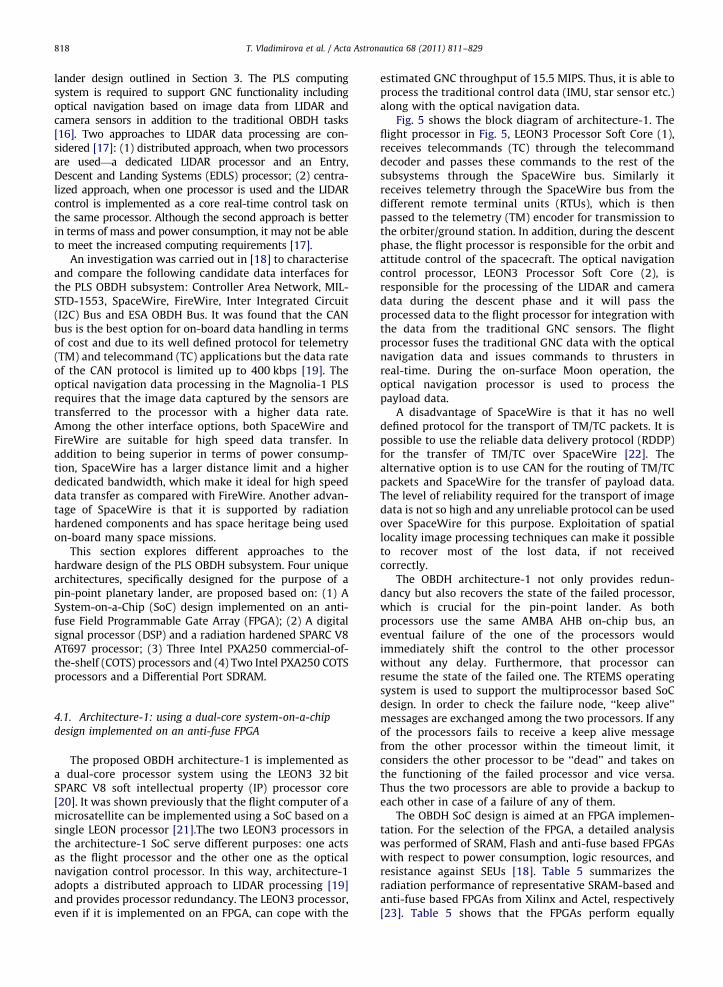
Fig. 5 shows the block diagram of architecture-1. Theflight processor in Fig. 5, LEON3 Processor Soft Core (1),receives telecommands (TC) through the telecommanddecoder and passes these commands to the rest of thesubsystems through the SpaceWire bus. Similarly itreceives telemetry through the SpaceWire bus from thedifferent remote terminal units (RTUs), which is thenpassed to the telemetry (TM) encoder for transmission tothe orbiter/ground station. In addition, during the descentphase, the flight processor is responsible for the orbit andattitude control of the spacecraft. The optical navigationcontrol processor, LEON3 Processor Soft Core (2), isresponsible for the processing of the LIDAR and cameradata during the descent phase and it will pass theprocessed data to the flight processor for integration withthe data from the traditional GNC sensors. The flightprocessor fuses the traditional GNC data with the opticalnavigation data and issues commands to thrusters inreal-time. During the on-surface Moon operation, theoptical navigation processor is used to process thepayload data.
A disadvantage of SpaceWire is that it has no welldefined protocol for the transport of TM/TC packets. It ispossible to use the reliable data delivery protocol (RDDP)for the transfer of TM/TC over SpaceWire [22]. Thealternative option is to use CAN for the routing of TM/TCpackets and SpaceWire for the transfer of payload data.The level of reliability required for the transport of imagedata is not so high and any unreliable protocol can be usedover SpaceWire for this purpose. Exploitation of spatiallocality image processing techniques can make it possibleto recover most of the lost data, if not receivedcorrectly.
The OBDH architecture-1 not only provides redun-dancy but also recovers the state of the failed processor,which is crucial for the pin-point lander. As bothprocessors use the same AMBA AHB on-chip bus, aneventual failure of the one of the processors wouldimmediately shift the control to the other processorwithout any delay. Furthermore, that processor canresume the state of the failed one. The RTEMS operatingsystem is used to support the multiprocessor based SoCdesign. In order to check the failure node, ‘‘keep alive’’messages are exchanged among the two processors. If anyof the processors fails to receive a keep alive messagefrom the other processor within the timeout limit, itconsiders the other processor to be ‘‘dead’’ and takes onthe functioning of the failed processor and vice versa.Thus the two processors are able to provide a backup toeach other in case of a failure of any of them.
The OBDH SoC design is aimed at an FPGA implemen-tation. For the selection of the FPGA, a detailed analysiswas performed of SRAM, Flash and anti-fuse based FPGAswith respect to power consumption, logic resources, andresistance against SEUs [18]. Table 5 summarizes theradiation performance of representative SRAM-based andanti-fuse based FPGAs from Xilinx and Actel, respectively[23]. Table 5 shows that the FPGAs perform equally
Payload RTUfor LowSpeed
Devices
Leon3 ProcessorSoft Core (2)
AOCSElectronics
Modem (UHF)
Rover
Camera
InertialNavigation
Sensors
LIDAR
HealthTelemetryRemoteTerminalUnit(RTU)
HealthSensors
RF FrontEnd
TM/TCEncoder/Decoder
RobotManipulatorTelemetry/
Telecommand
Actuators
SolarPanal
BatteriesPower
Conditioningunit(PCU)
PowerDistribution
unit
RTUPower
SPW
SPW
PayloadInstruments/
Sensors
MassMemory
64MB
ProgramMemory
8MB
ProgramMemory(4MB)
PayloadTelemetryPacketizer
SDRAM64MB
SDRAM64MB
Space WireRouter
Space WireRouter
AHB
SoC
RF FrontEnd
Leon3 ProcessorSoft Core (1)
Fig. 5. On-board data handling architecture-1 for the pin-point lander.
T. Vladimirova et al. / Acta Astronautica 68 (2011) 811–829 819
in terms of total ionizing dose (TID) and single eventlatch-up (SEL), but they differ significantly in terms oftheir resistance to SEUs, which is to be expected. The Actelanfi-fuse FPGAs were selected as the most suitable option
for the implementation of the SoC based flight computerof architecture-1 in view of the very high degree ofreliability required by the flight computer of the PLSmission.

Table 5Radiation performance comparison for Xilinx and Actel FPGAs [3].
FPGA Total ionizing
dose (krad)
Single event latch-up
(MeV cm2/mg)
Single event upset
(MeV cm2/mg)
SEU rate @ flip-flops SEU rate @ RAM
blocks
SEFI
RTAX250S 200 4100 450 1 per 19000 yr o10E�10 e/b–d n/a
RTAX1000S 200 4100 450 1 per 4500 yr o10E�10 e/b–d n/a
RTAX2000S 200 4100 450 1 per 2500 yr o10E-10 e/b-d n/a
XQR2V3000 200 4125 – 4.6 per day 1.4 per day 1 per 70 yr
XQR2V6000 200 4125 – 10.3 per day 2.2 per day 1 per 70 yr
Table 6Logic resources for the implementation of SoC on Actel RTAX4000 FPGA.
Soft IP core Required number
of logic gates
LEON3 Soft IP core (�2) 2�76% of
AX2000-CG624=3.04 M
Telemetry/telecommand
encoder/decoder
0.2 M
Payload data packetizer 0.2 M
Total 3.44 M
Table 7Power consumption for the SoC based architecture-1.
Device name Max. power consumption
FPGA (RTAX4000S) 2.5 W
SpaceWire interface node (�13) [26] 0.5 W�13=6.5 W
SpaceWire router (�2) [27] 4 W�2=8 W
Total 17 W
T. Vladimirova et al. / Acta Astronautica 68 (2011) 811–829820
In order to select the target Actel device the size of thedesign to be fitted onto the FPGA was estimated. The PLSOBDH SoC consists of the soft IP cores shown in Fig. 5. Thelogic resources required for the complete SoC design ofthe flight computer are calculated and given in Table 6[24]. Based on these logic resources and SEUs require-ments, the best option for the flight model of thisarchitecture was identified as the Actel RTAX4000S FPGAdevice, which has capacity equal to 4 M logic gates [18].The radiation protection provided by anti-fuse FPGAspermits the use of soft IP cores that do not have internalfault tolerant capability, which reduces the design effort.
The power calculation tool from Actel was used toestimate the power consumption of the SoC based flightcomputer [25]. The main input parameters for performingthe power calculation are the operating frequency, thenumber of S-cells, C-cells and the frequency of thehardwired clock. At 25 MHz, the power consumption forthe SoC based flight computer is 2.4992 W. Table 7 showsthe estimated values for the maximal power consumptionof architecture-1, which includes the power consumptionof all thirteen SpaceWire interface nodes [26] and the twoSpaceWire routers [27].
In conclusion it can be stated that the presented abovearchitecture-1 meets the fail-safe/fail-operational require-ment and features low power consumption, appropriatethroughput and design flexibility.
4.2. Architecture-2: using a radiation hardened processor
and a DSP processor
The proposed OBDH architecture-2 is based on twodifferent commercially available processors—the AT697SPARC V8 [28] processor from Atmel and the TMS320C670132 bit digital signal processor from Texas Instruments [29].AT697 acts as the main flight processor, while TMS320C6701serves as the optical navigation control processor. The flightprocessor tasks include on-board autonomy, clock manage-ment, power & thermal control, traditional attitude controland telemetry data handling. The other processor tasksinclude the processing of LIDAR and descent camera dataprocessing. For transfer of on-board data among the differentsubsystems, the CAN and SpaceWire protocols are used.During the descent phase of the Magnolia-1 pin-point lander,TMS320C6701 processes the data from the LIDAR anddescent camera and passes the extracted optical navigationdata to the flight processor through SpaceWire. The flightcomputer integrates this data with the traditional attitudesensors data and generates commands for the thrusters.During the on-surface operation phase, TMS320C6701 isresponsible for the operation, control and data handling ofscience instruments. In addition, it is responsible for therover communication, and transmits payload telemetry/telecommand to ground station.
Both processors meet the throughput requirements:TMS320C6701 offers 1 GFLOP and AT697—86 MIPS, andeach of them can handle all the tasks of the PLS on-boardcontrol and data processing on its own. AT697 is aradiation hardened SPARC V8 processor with radiationdose up to 300 krad and immunity against SEUs up to 1E-5/error/device/day [28]. TMS320C6701 is a commercial-off-the-shelf DSP and SEUs can disturb its operationalthough the probability of SEU occurrence during theextremely short critical descent phase is very low.A radiation hardened version of the TMS320C6701 DSPis also available, which is suitable for use in spaceenvironment [30].
Fig. 6 shows the block diagram of the OBDH architec-ture-2 for the pin-point planetary lander. The flightprocessor AT697 is in-charge of the data handling sub-system and it is also capable of distributing telecommandsto the payload RTU through the SpaceWire router. AT697receives commands from the orbiter/ground stationthrough the telemetry and telecommand (TM/TC) deco-der/encoder and passes this information to the remoteterminal units via the CAN bus. The data generated by theoptical navigation sensors (LIDAR/Camera) are processed by

AT697TMS320C6701
RS232
CAN
RS232
On-board Clk Reference
SPW
SPW
Data Memory
32MB
Payload RTUfor LowSpeed
DevicesModem (UHF)
Rover
HealthTelemetryRemoteTerminalUnit(RTU)
HealthSensors
RobotManipulatorTelemetry/
Telecommand
SolarPanal
BatteriesPower
Conditioningunit(PCU)
PowerDistribution
unit
RTUPower
PayloadInstruments/
Sensors
AOCSElectronics
Camera
InertialNavigation
Sensors
LIDAR
TM/TCEncoder/Decoder
PayloadEncoder/Decoder Actuators
MassMemory 64MB
ProgramMemory(4MB)
ProgramMemory(4MB)
Space WireRouter
Data Memory(32MB)
Fig. 6. On-board data handling architecture-2 for the pin-point lander.
Table 8Power consumption for the AT697 and TMS320C6701 DSP based
architecture-2.
Device name Max. power consumption
SpaceWire interface node (�8) [26] 0.5 W�8=4 W
SpaceWire router [27] 4 W�1=4 W
AT697 [28] 1 W@100 MHz
TMS320C6701 [29] 1.95 W
CAN Bus (�4) [19] 1 W�4=4 W
Total 14.95 W
T. Vladimirova et al. / Acta Astronautica 68 (2011) 811–829 821
the TMS320C6701 processor. As the memory interface ofTMS320C6701 limits the memory size to 52 MB, additionaldata packets from the camera and LIDAR are stored in themass memory via the SpaceWire interface, which increasesthe memory access time.
Although both processors are capable of providing veryhigh throughput, they should run at a lower speed tomask any single event transients (SETs). However, even ata lower speed, the performance of architecture-2 in termsof throughput is comparatively higher than that of theprevious architecture-1.
T. Vladimirova et al. / Acta Astronautica 68 (2011) 811–829822
The two processors are also used to provide failureredundancy. However, in case of a failure, it would bedifficult to resume the state of the failed processor, since
SPW
SPW
RS232
Intel PXA250
Camera
LIDAR
PayloadTelemetryPacketizer
Space WireRouter
RF FrontEnd
Payload RTUfor LowSpeed
DevicesModem (UHF)
Rover
RobotManipulatorTelemetry/
Telecommand
PayloadInstruments/
Sensors
Fig. 7. TMR based OBDH architectu
the data residing in the memory of the failed node will getlost. Hence this architecture does not provide a verystrong protection against a single-point failure.
InertialNavigation
Sensors
RS232
AOCSElectronics
TM/TCEncoder/Decoder
Actuators
ProgramMemory
8MB
SDRAM128 MB
Space WireRouter
RF FrontEnd
HealthTelemetryRemoteTerminalUnit(RTU)
HealthSensors
SolarPanal
BatteriesPower
Conditioningunit(PCU)
PowerDistribution
unit
RTUPower
re-3 for the pin-point lander.
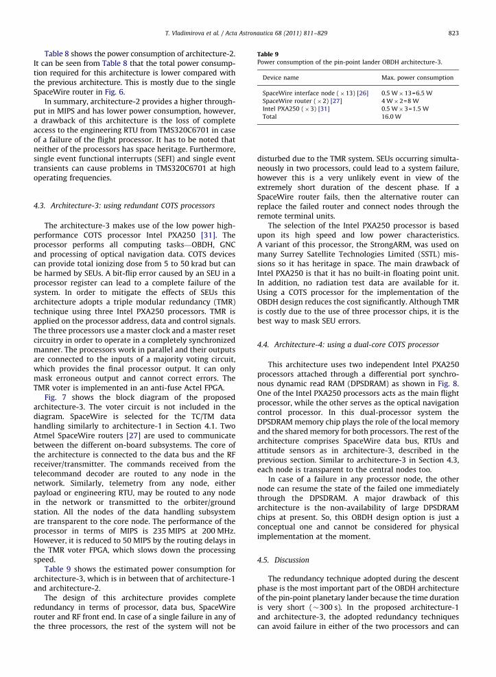
Table 9Power consumption of the pin-point lander OBDH architecture-3.
Device name Max. power consumption
SpaceWire interface node (�13) [26] 0.5 W�13=6.5 W
SpaceWire router (�2) [27] 4 W�2=8 W
Intel PXA250 (�3) [31] 0.5 W�3=1.5 W
Total 16.0 W
T. Vladimirova et al. / Acta Astronautica 68 (2011) 811–829 823
Table 8 shows the power consumption of architecture-2.It can be seen from Table 8 that the total power consump-tion required for this architecture is lower compared withthe previous architecture. This is mostly due to the singleSpaceWire router in Fig. 6.
In summary, architecture-2 provides a higher through-put in MIPS and has lower power consumption, however,a drawback of this architecture is the loss of completeaccess to the engineering RTU from TMS320C6701 in caseof a failure of the flight processor. It has to be noted thatneither of the processors has space heritage. Furthermore,single event functional interrupts (SEFI) and single eventtransients can cause problems in TMS320C6701 at highoperating frequencies.
4.3. Architecture-3: using redundant COTS processors
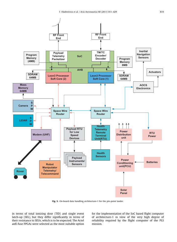
The architecture-3 makes use of the low power high-performance COTS processor Intel PXA250 [31]. Theprocessor performs all computing tasks—OBDH, GNCand processing of optical navigation data. COTS devicescan provide total ionizing dose from 5 to 50 krad but canbe harmed by SEUs. A bit-flip error caused by an SEU in aprocessor register can lead to a complete failure of thesystem. In order to mitigate the effects of SEUs thisarchitecture adopts a triple modular redundancy (TMR)technique using three Intel PXA250 processors. TMR isapplied on the processor address, data and control signals.The three processors use a master clock and a master resetcircuitry in order to operate in a completely synchronizedmanner. The processors work in parallel and their outputsare connected to the inputs of a majority voting circuit,which provides the final processor output. It can onlymask erroneous output and cannot correct errors. TheTMR voter is implemented in an anti-fuse Actel FPGA.
Fig. 7 shows the block diagram of the proposedarchitecture-3. The voter circuit is not included in thediagram. SpaceWire is selected for the TC/TM datahandling similarly to architecture-1 in Section 4.1. TwoAtmel SpaceWire routers [27] are used to communicatebetween the different on-board subsystems. The core ofthe architecture is connected to the data bus and the RFreceiver/transmitter. The commands received from thetelecommand decoder are routed to any node in thenetwork. Similarly, telemetry from any node, eitherpayload or engineering RTU, may be routed to any nodein the network or transmitted to the orbiter/groundstation. All the nodes of the data handling subsystemare transparent to the core node. The performance of theprocessor in terms of MIPS is 235 MIPS at 200 MHz.However, it is reduced to 50 MIPS by the routing delays inthe TMR voter FPGA, which slows down the processingspeed.
Table 9 shows the estimated power consumption forarchitecture-3, which is in between that of architecture-1and architecture-2.
The design of this architecture provides completeredundancy in terms of processor, data bus, SpaceWirerouter and RF front end. In case of a single failure in any ofthe three processors, the rest of the system will not be
disturbed due to the TMR system. SEUs occurring simulta-neously in two processors, could lead to a system failure,however this is a very unlikely event in view of theextremely short duration of the descent phase. If aSpaceWire router fails, then the alternative router canreplace the failed router and connect nodes through theremote terminal units.
The selection of the Intel PXA250 processor is basedupon its high speed and low power characteristics.A variant of this processor, the StrongARM, was used onmany Surrey Satellite Technologies Limited (SSTL) mis-sions so it has heritage in space. The main drawback ofIntel PXA250 is that it has no built-in floating point unit.In addition, no radiation test data are available for it.Using a COTS processor for the implementation of theOBDH design reduces the cost significantly. Although TMRis costly due to the use of three processor chips, it is thebest way to mask SEU errors.
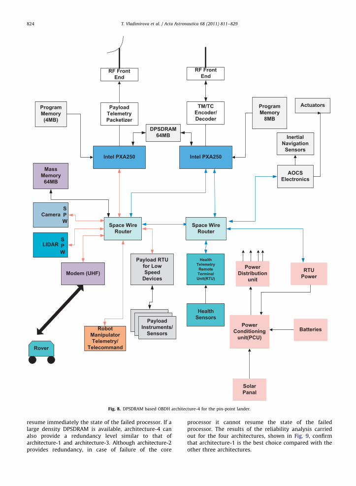
4.4. Architecture-4: using a dual-core COTS processor
This architecture uses two independent Intel PXA250processors attached through a differential port synchro-nous dynamic read RAM (DPSDRAM) as shown in Fig. 8.One of the Intel PXA250 processors acts as the main flightprocessor, while the other serves as the optical navigationcontrol processor. In this dual-processor system theDPSDRAM memory chip plays the role of the local memoryand the shared memory for both processors. The rest of thearchitecture comprises SpaceWire data bus, RTUs andattitude sensors as in architecture-3, described in theprevious section. Similar to architecture-3 in Section 4.3,each node is transparent to the central nodes too.
In case of a failure in any processor node, the othernode can resume the state of the failed one immediatelythrough the DPSDRAM. A major drawback of thisarchitecture is the non-availability of large DPSDRAMchips at present. So, this OBDH design option is just aconceptual one and cannot be considered for physicalimplementation at the moment.
4.5. Discussion
The redundancy technique adopted during the descentphase is the most important part of the OBDH architectureof the pin-point planetary lander because the time durationis very short (�300 s). In the proposed architecture-1and architecture-3, the adopted redundancy techniquescan avoid failure in either of the two processors and can
Intel PXA250
SPW
SPW
Payload RTUfor LowSpeed
Devices
AOCSElectronics
Modem (UHF)
Rover
Camera
InertialNavigation
Sensors
LIDAR
HealthTelemetryRemoteTerminalUnit(RTU)
HealthSensors
RF FrontEnd
TM/TCEncoder/Decoder
RobotManipulatorTelemetry/
Telecommand
Actuators
SolarPanal
BatteriesPower
Conditioningunit(PCU)
PowerDistribution
unit
RTUPower
PayloadInstruments/
Sensors
MassMemory
64MB
ProgramMemory
8MB
ProgramMemory(4MB)
PayloadTelemetryPacketizer
DPSDRAM64MB
Space WireRouter
Space WireRouter
RF FrontEnd
Intel PXA250
Fig. 8. DPSDRAM based OBDH architecture-4 for the pin-point lander.
T. Vladimirova et al. / Acta Astronautica 68 (2011) 811–829824
resume immediately the state of the failed processor. If alarge density DPSDRAM is available, architecture-4 canalso provide a redundancy level similar to that ofarchitecture-1 and architecture-3. Although architecture-2provides redundancy, in case of failure of the core
processor it cannot resume the state of the failedprocessor. The results of the reliability analysis carriedout for the four architectures, shown in Fig. 9, confirmthat architecture-1 is the best choice compared with theother three architectures.

0.94 0.95 0.96 0.97 0.98 0.99
Architecture-1
Architecture-2
Architecture-3
Architecture-4
0.99
0.96
0.98
0.975
Fig. 9. Reliability analysis for the pin-point lander architectures.
Table 10Comparison of the pin-point lander OBDH architectures.
Architecture Data bus Built-in floating
point unit
Failure
redundancy
Power
consumption
Performance
Architecture-1 SpaceWire Yes Complete 17 W 0.5 MIPS/MHz/Processor
Architecture-2 SpaceWire & CAN Yes Partial 14.3 W 0.86 MIPS/MHz-AT697
8.33 MFLOP/MHz-TMS320C6701
Architecture-3 SpaceWire No Complete 16 W 1.175 MIPS/MHz
T. Vladimirova et al. / Acta Astronautica 68 (2011) 811–829 825
The main features of the first three proposed archi-tectures are summarised in Table 10. As it can be seenfrom Table 10 architecture-2 outperforms the otherarchitectures in terms of power consumption andthroughput, however its poor failure redundancy andreliability do not make it a suitable candidate for thedesign of the pin-point lander OBDH subsystem in itspresent form. The proposed OBDH architecture-1 has beenidentified as the most favourable candidate for the PLSmission. Its performance in terms of MIPS is appropriatefor the execution of the pin-point landing on-board datahandling tasks; it offers good failure redundancy andlower cost. In addition, it provides design flexibility.Another merit of OBDH architecture-1 is that it can beprototyped easier and quicker compared to the otherarchitectures proposed in Section 4 due to the FPGAimplementation medium.
5. Experimental results
This section presents design and prototyping resultsfor the dual-core SoC flight computer module of archi-tecture-1, which has been selected as the best option for
the OBDH of the Magnolia-1 PLS, as discussed in section4.5 above.
5.1. Flight computer design
In any mission, the flight computer is the heart of the on-board command and data handling subsystem, whichreceives, validates, decodes, and distributes commands toother systems and gathers, processes, and formats house-keeping and mission data for downlink or use by an on-board computer [16]. The design of the flight computer forthe pin-point lander is guided by top level functionalrequirements, some of which are listed below:
�
Gathering and transmiting of telemetry from subsys-tems to TM Encoder. � Receiving and distributing of commands to relevantsubsystems for appropriate actions.
� Guidance, navigation and control (traditional+opticalnavigation & control).
� On-board autonomy support (Schemer, Sequencer,Scheduler, Fault Isolator, Mapper etc.)
� On-board data storage/management.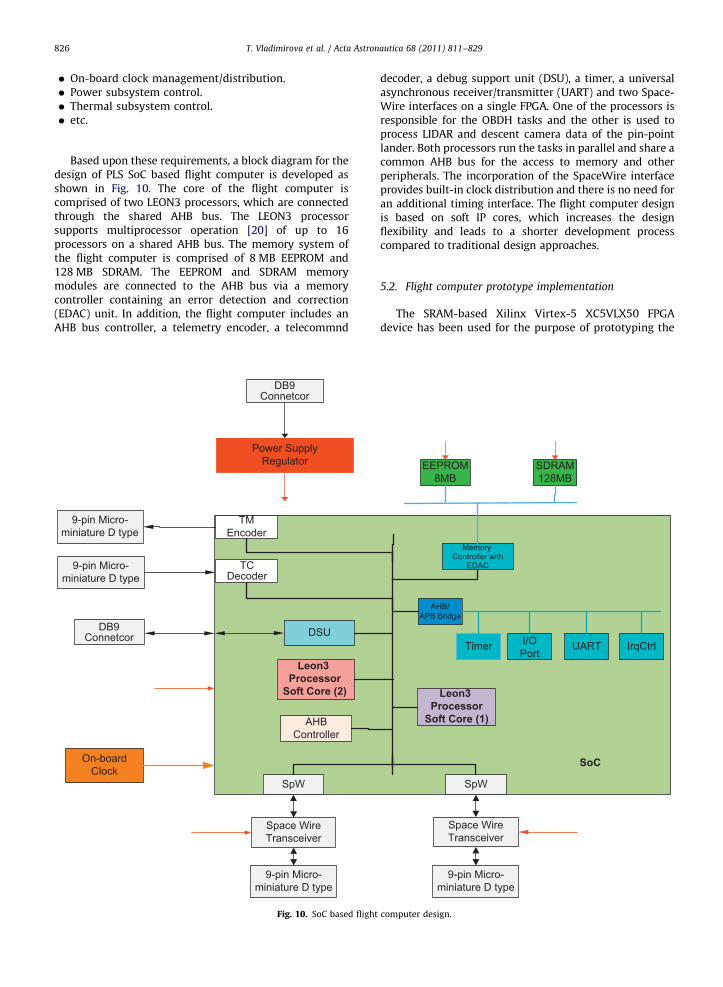
T. Vladimirova et al. / Acta Astronautica 68 (2011) 811–829826
�
m
m
On-board clock management/distribution.
� Power subsystem control. � Thermal subsystem control. � etc.Based upon these requirements, a block diagram for thedesign of PLS SoC based flight computer is developed asshown in Fig. 10. The core of the flight computer iscomprised of two LEON3 processors, which are connectedthrough the shared AHB bus. The LEON3 processorsupports multiprocessor operation [20] of up to 16processors on a shared AHB bus. The memory system ofthe flight computer is comprised of 8 MB EEPROM and128 MB SDRAM. The EEPROM and SDRAM memorymodules are connected to the AHB bus via a memorycontroller containing an error detection and correction(EDAC) unit. In addition, the flight computer includes anAHB bus controller, a telemetry encoder, a telecommnd
TMEncoder
Space WireTransceiver
Power SupplyRegulator
On-boardClock
SpW
AHBController
TCDecoder
DSU
9-pin Micro-iniature D type
9-pin Micro-iniature D type
9-pin Micro-miniature D type
DB9Connetcor
DB9Connetcor
Leon3 Processor
Soft Core (2)
Fig. 10. SoC based flight
decoder, a debug support unit (DSU), a timer, a universalasynchronous receiver/transmitter (UART) and two Space-Wire interfaces on a single FPGA. One of the processors isresponsible for the OBDH tasks and the other is used toprocess LIDAR and descent camera data of the pin-pointlander. Both processors run the tasks in parallel and share acommon AHB bus for the access to memory and otherperipherals. The incorporation of the SpaceWire interfaceprovides built-in clock distribution and there is no need foran additional timing interface. The flight computer designis based on soft IP cores, which increases the designflexibility and leads to a shorter development processcompared to traditional design approaches.
5.2. Flight computer prototype implementation
The SRAM-based Xilinx Virtex-5 XC5VLX50 FPGAdevice has been used for the purpose of prototyping the
Space WireTransceiver
SpW
Timer
AHB/APB Bridge
I/OPort
UART IrqCtrl
Memory Controller with
EDAC
EEPROM8MB
SDRAM128MB
9-pin Micro-miniature D type
SoC
Leon3 Processor
Soft Core (1)
computer design.
T. Vladimirova et al. / Acta Astronautica 68 (2011) 811–829 827
flight computer implementation although the design istargeted at the Actel anti-fuse FPGA RTAX4000. The rea-son for this is that SRAM-based FPGAs are re-programm-able and therefore more suitable for prototyping, whileanti-fuse FPGAs are one time programmable. The im-plemented SoC based flight computer includes two LEON3soft processors, AHB bus, UART, AHB/APB bridge, DSUUART, two timers and a LEON3 memory controller. TheCAD tools used for the implementation are the logicsimulator Modelsim and the Xilinxs Integrated SoftwareEnvironment (ISE) 10.1.
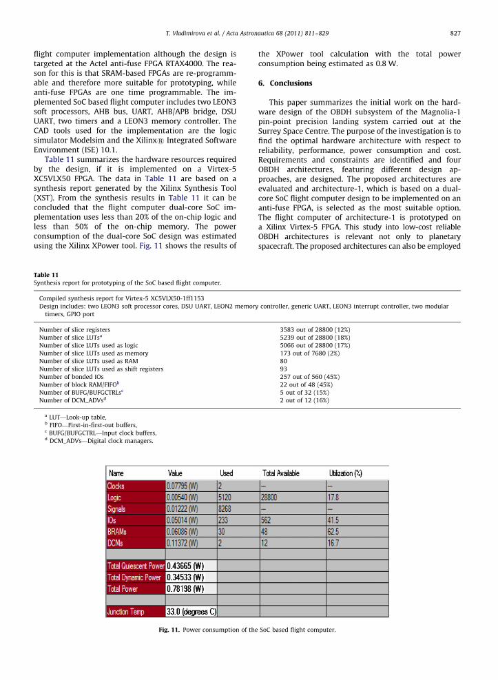
Table 11 summarizes the hardware resources requiredby the design, if it is implemented on a Virtex-5XC5VLX50 FPGA. The data in Table 11 are based on asynthesis report generated by the Xilinx Synthesis Tool(XST). From the synthesis results in Table 11 it can beconcluded that the flight computer dual-core SoC im-plementation uses less than 20% of the on-chip logic andless than 50% of the on-chip memory. The powerconsumption of the dual-core SoC design was estimatedusing the Xilinx XPower tool. Fig. 11 shows the results of
Table 11Synthesis report for prototyping of the SoC based flight computer.
Compiled synthesis report for Virtex-5 XC5VLX50-1ff1153
Design includes: two LEON3 soft processor cores, DSU UART, LEON2 memory
timers, GPIO port
Number of slice registers
Number of slice LUTsa
Number of slice LUTs used as logic
Number of slice LUTs used as memory
Number of slice LUTs used as RAM
Number of slice LUTs used as shift registers
Number of bonded IOs
Number of block RAM/FIFOb
Number of BUFG/BUFGCTRLsc
Number of DCM_ADVsd
a LUT—Look-up table,b FIFO—First-in-first-out buffers,c BUFG/BUFGCTRL—Input clock buffers,d DCM_ADVs—Digital clock managers.
Fig. 11. Power consumption of the
the XPower tool calculation with the total powerconsumption being estimated as 0.8 W.
6. Conclusions
This paper summarizes the initial work on the hard-ware design of the OBDH subsystem of the Magnolia-1pin-point precision landing system carried out at theSurrey Space Centre. The purpose of the investigation is tofind the optimal hardware architecture with respect toreliability, performance, power consumption and cost.Requirements and constraints are identified and fourOBDH architectures, featuring different design ap-proaches, are designed. The proposed architectures areevaluated and architecture-1, which is based on a dual-core SoC flight computer design to be implemented on ananti-fuse FPGA, is selected as the most suitable option.The flight computer of architecture-1 is prototyped ona Xilinx Virtex-5 FPGA. This study into low-cost reliableOBDH architectures is relevant not only to planetaryspacecraft. The proposed architectures can also be employed
controller, generic UART, LEON3 interrupt controller, two modular
3583 out of 28800 (12%)
5239 out of 28800 (18%)
5066 out of 28800 (17%)
173 out of 7680 (2%)
80
93
257 out of 560 (45%)
22 out of 48 (45%)
5 out of 32 (15%)
2 out of 12 (16%)
SoC based flight computer.
T. Vladimirova et al. / Acta Astronautica 68 (2011) 811–829828
in other space applications with similar requirements, forexample rapid response spacecraft.
The evaluation of the designed PLS OBDH architectures,presented in this paper, is the first attempt to assess thequalities of the different approaches at an early stage of thedesign. The evaluation process will be continued in thefuture. Further simulation and prototyping will be carriedout to finalize the hardware designs. In particular, theperformance of the AHB bus when operating undermultiple processors is to be quantified and a reliable datadelivery protocol for the telemetry/telecommand transmis-sion over SpaceWire is to be implemented in architecture-1. An efficient TMR voter, which can mask single eventupsets, is to be implemented in architecture-2. Improvingthe redundancy method in architecture-2 will allow thisefficient architecture to be considered for the mission too.The DPSDRAM in architecture-4 is a new concept, so theimplementation of this architecture will depend on thetechnology advancement in this area. Development ofsystem and application software will also be undertaken,which will allow us to refine the OBDH subsystemrequirements and perform functional tests on prototypedimplementations.
References
[1] C.D. Epp, T.B. Smith. Autonomous Precision Landing and HazardDetection Avoidance Technology (ALHAT), in Proceedings of the2006 IEEE Aerospace Conference, March 2006, Big Sky, Montana US.
[2] Y. Gao, A. Phipps, M. Taylor, I.A. Crawford, A.J. Ball, L. Wilson, A.Smith, A. Parker, M.N. Sweeting, A. da Silva Curiel, P. Davies.Concepts and Instruments of UK MoonLite & MoonRaker Missions,in: Proceedings of the International Astronautical Congress, IAC-07-3.6.B.01, 2007, Hyderabad, India.
[3] SSTL OBC 386, Datasheet, SSTL, /http://www.sstl.co.uk/assets/Downloads/Datasheet%20OBC%20386.pdfS.
[4] T. Vladimirova, M.N. Sweeting., System-on-a-chip development forsmall satellite on-board data handling, Journal of Aerospace Comput-ing, Information and Communication 1 (1) (2004) 36–43 AIAA.
[5] NASA, Apollo Operations Handbook Lunar Module LM10 andsubsequent, vol. I Subsystem Data, LMA790-3-LM 10 and Subse-quent, April 1, 1971.
[6] NASA Facts. Viking Mission to Mars, Datasheet, /http://www.jpl.nasa.gov/news/fact_sheets/viking.pdfS.
[7] N.A. Holmberg, R.P. Faust, and H.M. Holt, Viking ’75 SpacecraftDesign and Test Summary, vol. I—lander design, NASA ReferencePublication 1027, November 1980.
[8] NASA Facts. Mars Pathfinder. Datasheet, /http://www.jpl.nasa.gov/news/fact_sheets/mpf.pdfS.
[9] B.K. Muirhead, Mars Pathfinder Flight System Design and Imple-mentation, in: Proceedings of the Aerospace Applications Confer-ence, vol. 2, February 1996, pp. 159–171.
[10] ExoMars09 Concurrent Design Facility, European Space Agency, Ref.CDF-14(A), August 2002.
[11] S. Huixian, D. Shuwu, Y. Jianfeng, W. Ji, J. Jingshan, Scientificobjectives and payloads of Chang’E-1 lunar satellite, Journal ofEarth System Science 114 (6) (2005) 789–794.
[12] D. Neveu and J. De Lafontaine. Lidar-Based GNC for AutomaticRendezvous and Safe Landing (ARVSL) Study Synthesis andRecommendations for Safe Landing, ARVSL-TN-016-NGC, IssueDraft, Rev 0, 2005, NGC Aerospace Ltd.
[13] A. Phipps, A. da Silva Curiel, M. Meerman, D. Gibon, J. Ward. M.N.Sweeting. L. Gomes. Low Cost Lunar Orbiter System Design, in:Proceedings of the 2003 IEEE Aerospace Conference, vol. 1–225,March 2003, Big Sky, Montana US.
[14] V. Lappas, B. Smith, K. Hall , G. Olsen, C. Olsen, Systems Engineeringfor a Low Cost Lunar lander with Precision Landing Capabilities,Internal Report, Surrey Space Centre, February 28, 2008.
[15] C.I. Underwood, Lunar Surface Environment Definition, SurreySpace Centre, Internal Report March 17, 2008.
[16] J.R. Wertz, W.J. Larson, Space Mission Analysis and Design, third ed.,Microcosm Press and Kluwer Academics Publishers, Netherlands, 1999.
[17] J. Gebbie, M. Symonds, H. Winkelman, Autonomous entry, descentand landing—next-generation technologies for planetary missions,in: Proceedings of the Data Systems in Aerospace Conference,DASIA 2003, Prague, June 2003.
[18] M. Fayyaz, On-board data handling systems for a planetarylander—hardware architecture, M.Sc. Thesis, Surrey Space Centre,Department of Electronic Engineering, University of Surrey,Guildford, August 2008.
[19] A. Woodroffe, P. Madle, Applications and experience of CAN as alow cost OBDH bus system, in: Proceedings of Seventh Military andAerospace Applications of Programmable Devices and TechnologiesInternational Conference MAPLD’ 2004, P-106, September 2004,Washington, US, NASA.
[20] J. Gaisler, E. Catovic. Multi-core processor based on LEON3-FT IPcore (LEON3-FT-MP), in: Proceeding of the Data Systems inAerospace Conference, DASIA 2006, Berlin, 2006.
[21] H..Tiggeler, T..Vladimirova, D..Zheng, J..Gaisler. Experiences design-ing a system-on-a-chip for small satellite data processing andcontrol, in: Proceedings of Third International Conference onMilitary and Aerospace Applications of Programmable Devicesand Technologies, MAPLD’2000, September 2000, Laurel, Maryland,US, NASA, p. 20.
[22] G.P. Rakow. Reliable data delivery over spacewire, in: Proceedings of theNineth International Conference on Military and Aerospace Applicationsof Programmable Devices and Technologies, MAPLD’2000, September2006, Washington DC, US, p. 173.
[23] R. Roosta, A comparison of radiation-hard and radiation-tolerantFPGAs for space applications, NASA, JPL D-31228, December 30, 2004.
[24] J. Gaisler, Excel sheet for SoC area estimation, /http://www.gaisler.comS.
[25] Actel, Power Calculator for RTAX-S/SL, Datasheet, /http://www.actel.com/techdeocs/calculators.aspxS.
[26] Atmel,Triple SpaceWire links high speed controller AT7911,Datasheet, /http://www.atmel.com/S.
[27] Atmel,SpW-10X SpaceWire Router AT7910E, 7796A-Aero-04/08,Datasheet, /http://www.atmel.com/S.
[28] A.L.R. Pouponnot, Overview of the AT697E and AT697F micro-processor characteristics, functional differences, design features,availability, TEC-EDD/2008.14/ALRP, ESTEC/ESA, 31 July 2008.
[29] Texas Instruments,TMS320C6701 Floating-Point Digital SignalProcessor, Datasheet, /http://www.texas.comS.
[30] R. Joshi, R. Daniel, M. Shoga, M. Gauthier, Radiation hardnessevaluation of a class V 32 bit floating point digital signal processor,in: Proceedings of the IEEE Radiation Effects Workshop, pp. 70–78,July 2005.
[31] The Intels PXA250 Applications Processor, Datasheet, Intel, /http://www.intel.comS.
Tanya Vladimirova, MEng, MSc, PhD, CEng,MIET, MIEEE, is Reader at the Department ofElectronic Engineering, University of Surrey,UK. She is founder and leader of the VLSIDesign and Embedded Systems researchgroup at the Surrey Space Centre. Herresearch interests are in the areas of space-based wireless sensor networks, image pro-cessing for embedded systems, distributedcomputing, FPGA/ASIC design and artificialintelligence.
Muhammad Fayyaz completed his B.Sc. inElectrical Engineering at the University ofEngineering & Technology in Lahore, Paki-stan. In 2008, he was awarded a Master ofScience degree from the Department ofElectronic Engineering, University of Surrey,UK. His major areas of interest are embeddedsystems; SoC based designs, image proces-sing and wireless communication.

Astronautica 68 (2011) 811–829 829
Professor Sir Martin N. Sweeting, B.Sc.Hons.,
PhD, FRS, FREng., FIET, FRAeS, FBIS, SMIEEE,SMAIAA, MBIM, MIAA has pioneered theconcept of advanced microsatellites utilizingmodern commercial-off-the-shelf (COTS) de-vices for ‘affordable access to space.’ In 1985he formed a spin-off University company (SSTL- Surrey Satellite Technology Ltd) which hasdesigned, built, launched and operates in orbita total of 34 nano, micro, and mini-satellites -making SSTL the world’s leading microsatellitecompany. As Chief Executive of SSTL, he hasT. Vladimirova et al. / Acta
been responsible for the leadership and man-agement of the Company which by 2006 has grown to 210 commercialstaff and achieved a total export sales of over E110M. Sir Martin is alsoDirector of the Surrey Space Centre, leading a team of 80 faculty anddoctoral researchers investigating advanced small satellite concepts andtechniques. Sir Martin was knighted by HM The Queen in the 2002 BritishNew Year Honours for services to the small satellite industry.
Valentin Vitanov, MEng, MSc, PhD, FIET,MIEEE is Professor of Design, Manufactureand Management at the School of Engineer-ing at Durham University, UK. His researchinterests are divided into three closelyrelated streams: product design and technol-ogy optimization for improved reliability,production and operation management, si-mulation and statistical process control.He has had multiple project relationshipswith international companies includingEATON Corporation, GEC Marconi Defence
Systems, Airbus, Rolls Royce, BMW etc. He is an active member of six professional bodiesin the UK, USA and Europe.