A New Multithreaded Architecture Supporting Direct Execution of Esterel
18
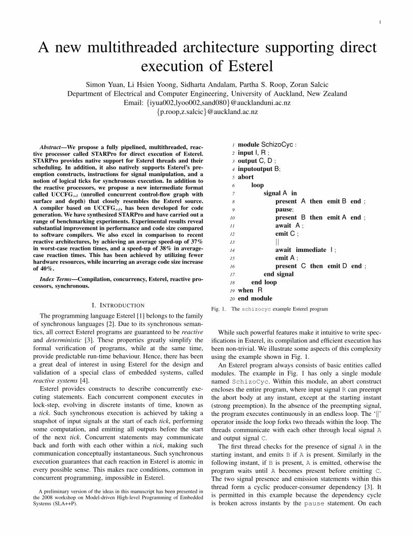
1 A new multithreaded architecture supporting direct execution of Esterel Simon Yuan, Li Hsien Yoong, Sidharta Andalam, Partha S. Roop, Zoran Salcic Department of Electrical and Computer Engineering, University of Auckland, New Zealand Email: {iyua002,lyoo002,sand080}@aucklanduni.ac.nz {p.roop,z.salcic}@auckland.ac.nz Abstract—We propose a fully pipelined, multithreaded, reac- tive processor called STARPro for direct execution of Esterel. STARPro provides native support for Esterel threads and their scheduling. In addition, it also natively supports Esterel’s pre- emption constructs, instructions for signal manipulation, and a notion of logical ticks for synchronous execution. In addition to the reactive processors, we propose a new intermediate format called UCCFG sd (unrolled concurrent control-flow graph with surface and depth) that closely resembles the Esterel source. A compiler based on UCCFG sd , has been developed for code generation. We have synthesized STARPro and have carried out a range of benchmarking experiments. Experimental results reveal substantial improvement in performance and code size compared to software compilers. We also excel in comparison to recent reactive architectures, by achieving an average speed-up of 37% in worst-case reaction times, and a speed-up of 38% in average- case reaction times. This has been achieved by utilizing fewer hardware resources, while incurring an average code size increase of 40%. Index Terms—Compilation, concurrency, Esterel, reactive pro- cessors, synchronous. I. I NTRODUCTION The programming language Esterel [1] belongs to the family of synchronous languages [2]. Due to its synchronous seman- tics, all correct Esterel programs are guaranteed to be reactive and deterministic [3]. These properties greatly simplify the formal verification of programs, while at the same time, provide predictable run-time behaviour. Hence, there has been a great deal of interest in using Esterel for the design and validation of a special class of embedded systems, called reactive systems [4]. Esterel provides constructs to describe concurrently exe- cuting statements. Each concurrent component executes in lock-step, evolving in discrete instants of time, known as a tick. Such synchronous execution is achieved by taking a snapshot of input signals at the start of each tick, performing some computation, and emitting all outputs before the start of the next tick. Concurrent statements may communicate back and forth with each other within a tick, making such communication conceptually instantaneous. Such synchronous execution guarantees that each reaction in Esterel is atomic in every possible sense. This makes race conditions, common in concurrent programming, impossible in Esterel. A preliminary version of the ideas in this manuscript has been presented in the 2008 workshop on Model-driven High-level Programming of Embedded Systems (SLA++P). 1 module SchizoCyc : 2 input I, R ; 3 output C, D ; 4 inputoutput B; 5 abort 6 loop 7 signal A in 8 present A then emit B end ; 9 pause; 10 present B then emit A end ; 11 await A ; 12 emit C ; 13 || 14 await immediate I ; 15 emit A ; 16 present C then emit D end ; 17 end signal 18 end loop 19 when R 20 end module Fig. 1. The schizocyc example Esterel program While such powerful features make it intuitive to write spec- ifications in Esterel, its compilation and efficient execution has been non-trivial. We illustrate some aspects of this complexity using the example shown in Fig. 1. An Esterel program always consists of basic entities called modules. The example in Fig. 1 has only a single module named SchizoCyc. Within this module, an abort construct encloses the entire program, where input signal R can preempt the abort body at any instant, except at the starting instant (strong preemption). In the absence of the preempting signal, the program executes continuously in an endless loop. The ‘k’ operator inside the loop forks two threads within the loop. The threads communicate with each other through local signal A and output signal C. The first thread checks for the presence of signal A in the starting instant, and emits B if A is present. Similarly in the following instant, if B is present, A is emitted, otherwise the program waits until A becomes present before emitting C. The two signal presence and emission statements within this thread form a cyclic producer-consumer dependency [3]. It is permitted in this example because the dependency cycle is broken across instants by the pause statement. On each
-
Upload
independent -
Category
Documents
-
view
2 -
download
0
Transcript of A New Multithreaded Architecture Supporting Direct Execution of Esterel
1
A new multithreaded architecture supporting directexecution of Esterel
Simon Yuan, Li Hsien Yoong, Sidharta Andalam, Partha S. Roop, Zoran SalcicDepartment of Electrical and Computer Engineering, University of Auckland, New Zealand
Email: {iyua002,lyoo002,sand080}@aucklanduni.ac.nz{p.roop,z.salcic}@auckland.ac.nz
Abstract—We propose a fully pipelined, multithreaded, reac-tive processor called STARPro for direct execution of Esterel.STARPro provides native support for Esterel threads and theirscheduling. In addition, it also natively supports Esterel’s pre-emption constructs, instructions for signal manipulation, and anotion of logical ticks for synchronous execution. In addition tothe reactive processors, we propose a new intermediate formatcalled UCCFGsd (unrolled concurrent control-flow graph withsurface and depth) that closely resembles the Esterel source.A compiler based on UCCFGsd, has been developed for codegeneration. We have synthesized STARPro and have carried out arange of benchmarking experiments. Experimental results revealsubstantial improvement in performance and code size comparedto software compilers. We also excel in comparison to recentreactive architectures, by achieving an average speed-up of 37%in worst-case reaction times, and a speed-up of 38% in average-case reaction times. This has been achieved by utilizing fewerhardware resources, while incurring an average code size increaseof 40%.
Index Terms—Compilation, concurrency, Esterel, reactive pro-cessors, synchronous.
I. INTRODUCTION
The programming language Esterel [1] belongs to the familyof synchronous languages [2]. Due to its synchronous seman-tics, all correct Esterel programs are guaranteed to be reactiveand deterministic [3]. These properties greatly simplify theformal verification of programs, while at the same time,provide predictable run-time behaviour. Hence, there has beena great deal of interest in using Esterel for the design andvalidation of a special class of embedded systems, calledreactive systems [4].
Esterel provides constructs to describe concurrently exe-cuting statements. Each concurrent component executes inlock-step, evolving in discrete instants of time, known asa tick. Such synchronous execution is achieved by taking asnapshot of input signals at the start of each tick, performingsome computation, and emitting all outputs before the startof the next tick. Concurrent statements may communicateback and forth with each other within a tick, making suchcommunication conceptually instantaneous. Such synchronousexecution guarantees that each reaction in Esterel is atomic inevery possible sense. This makes race conditions, common inconcurrent programming, impossible in Esterel.
A preliminary version of the ideas in this manuscript has been presented inthe 2008 workshop on Model-driven High-level Programming of EmbeddedSystems (SLA++P).
1 module SchizoCyc :2 input I, R ;3 output C, D ;4 inputoutput B;5 abort6 loop7 signal A in8 present A then emit B end ;9 pause;
10 present B then emit A end ;11 await A ;12 emit C ;13 ||14 await immediate I ;15 emit A ;16 present C then emit D end ;17 end signal18 end loop19 when R20 end module
Fig. 1. The schizocyc example Esterel program
While such powerful features make it intuitive to write spec-ifications in Esterel, its compilation and efficient execution hasbeen non-trivial. We illustrate some aspects of this complexityusing the example shown in Fig. 1.
An Esterel program always consists of basic entities calledmodules. The example in Fig. 1 has only a single modulenamed SchizoCyc. Within this module, an abort constructencloses the entire program, where input signal R can preemptthe abort body at any instant, except at the starting instant(strong preemption). In the absence of the preempting signal,the program executes continuously in an endless loop. The ‘‖’operator inside the loop forks two threads within the loop. Thethreads communicate with each other through local signal Aand output signal C.
The first thread checks for the presence of signal A in thestarting instant, and emits B if A is present. Similarly in thefollowing instant, if B is present, A is emitted, otherwise theprogram waits until A becomes present before emitting C.The two signal presence and emission statements within thisthread form a cyclic producer-consumer dependency [3]. Itis permitted in this example because the dependency cycleis broken across instants by the pause statement. On each
2
iteration of the loop, signal A will be reincarnated [5]. Thisis equivalent to unrolling the loop body to produce a newdeclaration of the local signal A for each pass of the loop.
The second thread, waits for input I to become present.As soon as I becomes present, A is emitted immediately.Following the emission of A, if C is emitted by the first thread,D will also be emitted in the same instant. Because of signalreincarnation, the example in Fig. 1 is said to be schizophrenic.When I is present in the first instant, signal A can be bothpresent and absent in the same instant. Hence, SchizoCycis named after the schizophrenic behaviour, and a cyclicdependency. The SchizoCyc example illustrates some of theaspects that make the compilation and efficient execution ofEsterel challenging. Correct scheduling of the threads suchthat the data dependencies between the threads are satisfied,contributes significantly to this complexity. Moreover, preserv-ing the synchronous semantics of Esterel in compiled code isalready, in itself, non-trivial.
Several approaches exist for dealing with these complexitiesin the compilation and execution of Esterel programs. Theseinclude hardware compilation [3], software compilation forgeneral-purpose microprocessors [6], [7], [8], and architecture-specific compilation for reactive processors optimized for Es-terel [9], [10]. While the translation of Esterel to digital circuitsin hardware is relatively straightforward, the generation of effi-cient software code has been challenging. Software compilerstypically map Esterel programs into another language, such asC, so that they can be executed on standard microprocessors.Consequently, concurrent statements in Esterel need to beinterleaved and appropriately scheduled in order to producean equivalent sequential program. This requires additionalsynchronization mechanisms to be added to preserve Esterel’ssemantics. Such mechanisms introduce extra execution over-head and increase the required memory footprint.
The architecture-specific approach for Esterel execution, incontrast, relies on custom microprocessors that have beenaugmented with an instruction set, which enables efficientmapping of Esterel statements to assembly code. This ap-proach yields very compact machine code, as well as efficientexecution, and will be the focus of this paper. We presenta novel multithreaded processor, named STARPro (Simulta-neous multiThreaded Auckland Reactive Processor), and anEsterel compiler for it, that achieves significant speed-up andcode size compaction over traditional methods for softwareimplementations of Esterel.
The rest of this paper is organized as follows. Section II re-views previous work related to architecture-specific executionof Esterel. Section III then presents STARPro’s architecture,which is followed by a description of its instruction set archi-tecture (ISA) in Section IV. Section V covers code generationfrom the intermediate format and the execution semantics.In Section VI, we show the experimental results obtainedfor some benchmarks. We finally end with some concludingremarks in Section VII.
II. RELATED WORK
The EMPEROR multiprocessor architecture [9] was thefirst attempt at the direct execution of Esterel using a set
of reactive processor cores. These cores communicate andsynchronize with each other using a thread control block toachieve synchronous execution. It executes Esterel programsby resolving signal dependencies during run-time using a dual-rail encoding of signals [11]. This approach, while achievinggood execution times, required excessively high hardwareresources.
In contrast to the approach taken in EMPEROR, newcontributions were also made to the idea of reactive processingthrough the KEP series of processors [12], [13], [14], [10]. TheKEP series of processors are custom designed architecturesthat have evolved from each generation with incrementalsupport for executing Esterel. The most recent processor,KEP3a [10], is capable of preserving the semantics of the fulllanguage. It also provides a multithreaded execution platformto support the concurrency in Esterel. This approach hasyielded impressive code size compaction and execution times,thus affirming again the benefits of reactive processors forexecuting Esterel.
However, there are many improvements that could be madeover KEP’s approach to reactive processor design. At present,KEP3a employs a non-pipelined architecture, which supportsEsterel’s semantics almost entirely in hardware. This approachresults in a complex hardware design, with a consequentlylower operating clock frequency.
In contrast, this paper presents a novel multithreaded pro-cessor, named STARPro [15], that provides an alterative ap-proach to direct execution compared to KEP3a. STARPro usesvariable tick lengths and a pipelined architecture to obtainmuch better average performance compared to KEP3a. Thishas been achieved using far fewer logic gates for processorimplementation, while maintaining code sizes that are slightlyinferior to KEP3a.
Plummer et al [16] have explored another approach of exe-cuting Esterel using a virtual machine (VM). The VM providescustomized instructions to support Esterel’s execution, similarto STARPro. The key difference is that a virtual machine isimplemented as software, whereas STARPro is a hardwareplatform. The code size in both approaches are superior whencompared with traditional Esterel compilers. However, theVM approach is significantly slower than traditional Esterelcompilers [16].
III. ARCHITECTURE OF THE STARPRO PROCESSOR
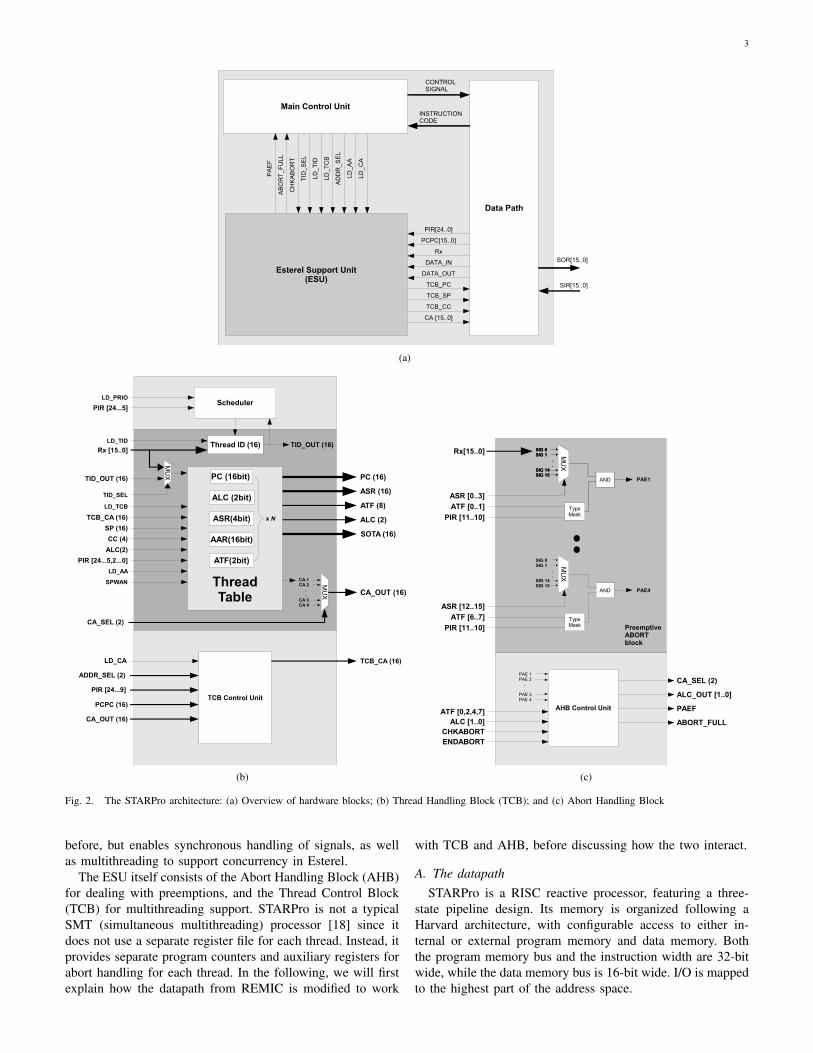
STARPro’s design extends our previous reactive architec-ture REMIC [17]. REMIC is a three-stage pipelined reactiveprocessor that was inspired by Esterel, though it was notdesigned to provide support for executing Esterel. REMIC hasa Reactive Functional Unit (RFU), attached to the control unitand datapath of the processor core, that provides instruction setsupport for efficient handling of asynchronous I/O in reactiveapplications. The RFU, however, is not well-suited for Esterelprograms, which requires I/O to be handled synchronously.Moreover, REMIC has no support for concurrency. Hence,we have developed the Esterel Support Unit (ESU) to replacethe RFU within REMIC, as illustrated in Fig. 2(a). TheESU still interfaces with the control unit and the datapath as
3
Main Control Unit
Data Path
CONTROLSIGNAL
SOR[15..0]
INSTRUCTIONCODE
Esterel Support Unit(ESU)
SIR[15..0]
PA
EF
AB
OR
T_
FU
LL
CH
KA
BO
RT
TID
_S
EL
LD_
TID
LD_
TC
B
AD
DR
_S
EL
LD_
AA
LD
_C
A
PIR[24..0]
DATA_OUT
CA [15..0]
DATA_IN
Rx
PCPC[15..0]
TCB_PC
TCB_SP
TCB_CC
(a)
Thread ID (16) TID_OUT (16)
TID_OUT (16)
CA 1CA 2 . .CA 3CA 4
CA_SEL (2)
CA_OUT (16)
MUX
ASR (16)
ATF (8)
ALC (2)
SOTA (16)
TCB_CA (16)
SP (16)
CC (4)
PIR [24...5,2...0]
LD_AA
LD_TID
LD_TCB
MUX
TID_SEL
TCB Control UnitPCPC (16)
CA_OUT (16)
LD_CA TCB_CA (16)
PIR [24...9]
ADDR_SEL (2)
ALC(2)
ThreadTable
SPWAN
PC (16)
SchedulerLD_PRIO
PC (16bit)
ALC (2bit)
AAR(16bit)
ASR(4bit)
ATF(2bit)
x N
PIR [24...5]
Rx [15..0]
(b)
MU
X
SIG 0 SIG 1 . .SIG 14SIG 15
XNOR
AND PAE1
PAE4
PreemptiveABORTblock
Rx[15..0]
ASR [0..3]
ATF [0..1]
PIR [11..10]
ASR [12..15]
ATF [6..7]
PIR [11..10]
MU
X
SIG 0 SIG 1 . .SIG 14SIG 15
TypeMask
AND
MU
X
SIG 0 SIG 1 . .SIG 14SIG 15
TypeMask
AND
AHB Control Unit
PAE 1PAE 2 . .PAE 3PAE 4
ALC [1..0]CHKABORTENDABORT
CA_SEL (2)
ALC_OUT [1..0]
PAEF
ABORT_FULL
ATF [0,2,4,7]
(c)
Fig. 2. The STARPro architecture: (a) Overview of hardware blocks; (b) Thread Handling Block (TCB); and (c) Abort Handling Block
before, but enables synchronous handling of signals, as wellas multithreading to support concurrency in Esterel.
The ESU itself consists of the Abort Handling Block (AHB)for dealing with preemptions, and the Thread Control Block(TCB) for multithreading support. STARPro is not a typicalSMT (simultaneous multithreading) processor [18] since itdoes not use a separate register file for each thread. Instead, itprovides separate program counters and auxiliary registers forabort handling for each thread. In the following, we will firstexplain how the datapath from REMIC is modified to work
with TCB and AHB, before discussing how the two interact.
A. The datapathSTARPro is a RISC reactive processor, featuring a three-
state pipeline design. Its memory is organized following aHarvard architecture, with configurable access to either in-ternal or external program memory and data memory. Boththe program memory bus and the instruction width are 32-bitwide, while the data memory bus is 16-bit wide. I/O is mappedto the highest part of the address space.
4
The datapath contains an 8-bank 16-bit wide register fileas general purpose registers. Next to the register file is theArithmetic Logic Unit (ALU). It supports standard operationssuch as addition, subtraction, and bit shifting, just to name afew.
To support the additional needs of the ESU, the datapathof REMIC [17] has been extended with additional ports tothe datapath external interface. The changes allow the ESUto directly access the register file, which now also serve assignal register. It allows any data loaded into the registers tobe treated as signals. The other important modification adds anew input to the program counter multiplexer. This additionalconnection is required for loading a new program addresswhen a preemption occurs. In the following, we will explainin more detail how the ESU use these new connections to thedatapath.
B. The Thread Control Block (TCB)
An Esterel program may have multiple threads. The TCBmaintains the status of individual threads while emulating thesynchronous concurrency using static thread scheduling. InFig. 2(b), the TCB itself is composed of a scheduler thatmaintains thread context, a thread table, and a TCB controlunit.
The thread table stores the current program counter and theabort context1 associated with the current thread. Both theprogram counter and the abort context are sufficient to fullydescribe a thread’s context in STARPro. The number of threadsthat can be stored in the thread table is parameterizable in ourdesign, and is limited only to the hardware resources available.
The thread table is indexed by the Thread ID register. Theentry indexed by that register determines the thread which iscurrently being executed. When the LD_TCB signal is asserted,write access is enabled to the table for a thread context tobe saved. Switching between threads then becomes a simplematter of changing the value stored in the thread ID register. Anew thread ID value is loaded through the Rx bus connectedto the datapath. During the processor’s reset, the thread IDregister will be initialized to zero. Consequently, the ID of theroot thread of all programs will be assigned a default value ofzero by the STARPro compiler.
The other remaining important component of the TCB is thescheduler. The scheduler stores the priority and a notion of alocal tick for each thread as boolean flags. We say that the localtick for a thread has elapsed whenever a pause statement isreached. This differs from the global tick for an entire Esterelprogram, which only elapses when all running threads havecompleted their local ticks. In STARPro, the pause statementis mapped to the PAUSE instruction, which is used within theprocessor to indicate the completion of the local tick for agiven thread.
The scheduler will always select the thread with the highestpriority for execution. In doing so, it ignores all the threadsthat have either completed their local ticks, or are otherwiseinactive. A thread is considered to be inactive if its prioritynumber is set to the lowest possible priority. When the local
1The abort context will be described in Section III-C.
tick of all the currently active threads have elapsed, the globaltick completes, and a compiler-generated management threadis selected to sample new inputs and to clear all output signalsfor the next global tick.
The distinction between local and global ticks is actually thekey idea that facilitates the use of variable tick durations inSTARPro. This idea was first introduced in [9], and has beenadapted for our current design. By relying on the completion ofindividual local ticks to determine the final duration of a globaltick, the global tick duration is dynamically changed and isequal to the actual computational time required for executinga number of threads in any instant.
C. The Abort Handling Block (AHB)
The AHB is used to monitor aborting signals, and to triggerthe appropriate preemptions if necessary. In Esterel, the prior-ity of the abort construct depends on the level of its nesting.An outer abort construct will always have higher priority overthose nested below it. The AHB supports this feature byproviding hardware-based priority resolution (controlled by afinite state machine in the AHB) for the abort constructs. Thedepth of nested aborts is fully parameterizable in our design.Fig. 2(c) depicts an AHB that has been configured with fourlevels of aborts for each thread.
The AHB relies on the abort context provided by the TCBto trigger abortions. An abort context consists of the followingelements:• Rx: This is the bus that connects to a 16-bit register
selected from the register file in the datapath. The registerhas to be loaded with the status of 16 I/O signals at a timefrom memory. It is updated at the beginning of every tick,and is used by the AHB to evaluate the current status ofthe aborting signals.
• ASR (Abort Signal Register): This stores the ID of thesignal which needs to be monitored during execution ofan abort body.
• AAR (Abort Address Register): This stores the continu-ation address, to which the thread must jump to, shouldpreemption happens
• ATF (Abort Type Flags): STARPro supports the differenttypes of abortions in Esterel. Abortions can either bestrong or weak, and may be either immediate or non-immediate. These are orthogonal to each other, resultingin four distinct behaviours for abortions in Esterel.
• ALC (Abort Level Count): Each thread can consist ofan arbitrary number of nested aborts. This register isincremented as the depth of nested aborts increases.
The TCB stores the ASR, ATF, and ALC for each thread,and provides this abort context of the current running thread tothe AHB. The AHB does not contain any memory element andit is purely control. When instructed by the main control unit,the AHB checks all abort levels that have been initialized. If apreemption is taken, it provides an index (CA_SEL in Fig. 3)that selects the continuation address (AAR, stored in the threadtable inside the TCB), as well as an updated ALC, back to theTCB. The TCB directly provides the continuation address tothe datapath, and hence the AAR is the only part of the abort
5
context not passed to the AHB. The activation and deactivationof abort levels are also controlled by the TCB control unit.
Abort Handling Block(AHB)
ESU
ASR (16)
ATF (8)
CA_SEL (2)
ALC (2)
ALC_OUT (2)
Thread Control Block(TCB)
Main Control Unit
CHKABORT
Reset
A0
A1
A2
A3
A4
a00
a11
a22
a33
a44
a01
a12
a23
a34
a10
a21
a32
a43
a20
a31
a42
a30
a41
a40
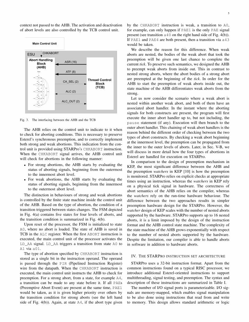
Fig. 3. The interfacing between the AHB and the TCB
The AHB relies on the control unit to indicate to it whento check for aborting conditions. This is necessary to preserveEsterel’s synchronous preemption, and to correctly implementboth strong and weak abortions. This indication from the con-trol unit is provided using STARPro’s CHKABORT instruction.When the CHKABORT signal arrives, the AHB control unitwill check for abortions in the following manner:• For strong abortions, the AHB starts by evaluating the
status of aborting signals, beginning from the outermostto the innermost abort level.
• For weak abortions, the AHB starts by evaluating thestatus of aborting signals, beginning from the innermostto the outermost abort level.
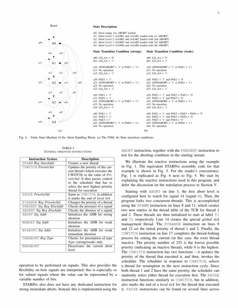
The distinction in behaviours of strong and weak abortionsis controlled by the finite state machine inside the control unitof the AHB. Based on the type of abortion, the condition of atransition triggered between states changes. The FSM depictedin Fig. 4(a) contains five states for four levels of aborts, andthe transition condition is summarized in Fig. 4(b).
Upon reset of the processor, the FSM is initialized to stateA0, where no abort is loaded. The state of AHB is saved inTCB in the ALC register. When the first ABORT instruction isexecuted, the main control unit of the processor activates theLD_AA signal. LD_AA triggers a transition from state A0 toA1 via a01.
The type of abortion specified by CHKABORT instruction isstored as a single bit in the instruction operand. The operandis passed through the PIR (Pipelined Instruction Register)wire from the datapath. When the CHKABORT instruction isexecuted, the main control unit instructs the AHB to check forpreemption. For a strong abort, from a state, for example A4,a transition can be made to any state before it. If all PAEs(Preemptive Abort Event) are present at the same time, PAE1would be taken, as it is given higher priority over others bythe transition condition for strong aborts (see the left handside of Fig. 4(b)). Again, at state A4, if the abort type given
by the CHKABORT instruction is weak, a transition to A0,for example, can only happen if PAE1 is the only PAE signalpresent (see transition a40 on the right hand side of Fig. 4(b)).If PAE1 and PAE4 are both present, then a transition via a43would be taken.
We describe the reason for this difference. When weakaborts are nested, the bodies of the weak abort that took thepreemption will be given one last chance to complete thecurrent tick. To preserve such semantics, we designed the AHBto preempt weak aborts from inside out. This in contrast tonested strong aborts, where the abort bodies of a strong abortare preempted at the beginning of the tick. In order for theAHB to start the preemption of weak aborts inside out, thestate machine of the AHB differentiates weak aborts from thestrong.
Let us now consider the scenario where a weak abort isnested within another weak abort, and both of them have anassociated abort handler. In the instant where the abortingsignals for both constructs are present, the program will firstexecute the inner abort handler up to, but not including, thepause statement (if any). Execution will then branch to theouter abort handler. This chaining of weak abort handlers is thereason behind the different order of checking between the twotypes of abort constructs. By checking a weak abort beginningat the innermost level, the preemption can be propagated fromthe inner to the outer levels of aborts. Later, in Sec. V-B, wewill discuss in more detail how the four types of abortions inEsterel are handled for execution on STARPro.
In comparison to the design of preemption mechanism inKEP, the most significant difference between the AHB andthe preemption watchers in KEP [10] is how the preemptionis monitored. STARPro relies on explicit checks at appropriatetimes using an instruction, whereas the watchers in KEP relyon a physical tick signal in hardware. The correctness ofabort semantics of the AHB relies on the compiler, whereasthe watchers rely on the run-time hardware behaviour. Thedifference between the two approaches results in simplerpreemption hardware design for the STARPro. However, thewatcher design of KEP scales with the number of nested abortssupported by the hardware. STARPro supports up to 16 nestedaborts, it is a limit imposed by the design of the instructionformat and the AHB control state machine. The complexity ofthe state machine of the AHB grows exponentially with respectto the number of nested aborts supported by the hardware.Despite the limitation, our compiler is able to handle abortsin software in addition to hardware aborts.
IV. THE STARPRO INSTRUCTION SET ARCHITECTURE
STARPro uses a 32-bit instruction format. Apart from thecommon instructions found on a typical RISC processor, weintroduce additional Esterel-oriented instructions to supportmultithreading, signal testing, and preemption. The syntax anddescription of these instructions are summarized in Table I.
The number of I/O signal ports is parameterizable. I/O sig-nals are memory-mapped, which enables signal manipulationto be also done using instructions that read from and writeto memory. This design allows standard arithmetic or logic
6
Reset
A0
A1
A2
A3
A4
a00
a11
a22
a33
a44
a01
a12
a23
a34
a10
a21
a32
a43
a20
a31
a42
a30
a41
a40
(a)
State Description:
A0: Abort empty (no ABORT loaded)A1: Abort Level 1 (AASR1 and AAAR1 loaded with 1st ABORT)A2: Abort Level 2 (AASR2 and AAAR2 loaded with 2nd ABORT)A3: Abort Level 3 (AASR3 and AAAR3 loaded with 3rd ABORT)A4: Abort Level 4 (AASR4 and AAAR4 loaded with 4th ABORT)
State Transition Condition (strong): State Transition Condition (weak):
a00: LD AA = ‘0’ a00: LD AA = ‘0’a01: LD AA = ‘1’ a01: LD AA = ‘1’
a10: (ENDABORT = ‘1’ or PAE1 = ‘1’) a10: (ENDABORT = ‘1’ or PAE1 = ‘1’)a11: No operation a11: No operationa12: LD AA = ‘1’ a12: LD AA = ‘1’
a20: PAE1 = ‘1’ a20: PAE1 = ‘1’ and PAE2 = ’0’a21: (ENDABORT = ‘1’ or PAE2 = ‘1’) a21: (ENDABORT = ‘1’ or PAE2 = ‘1’)a22: No operation a22: No operationa23: LD AA = ‘1’ a23: LD AA = ‘1’
a30: PAE1 = ‘1’ a30: PAE1 = ‘1’ and PAE2 = PAE3 = ’0’a31: PAE2 = ‘1’ a31: PAE2 = ‘1’ and PAE3 = ’0’a32: (ENDABORT = ‘1’ or PAE3 = ‘1’) a32: (ENDABORT = ‘1’ or PAE3 = ‘1’)a33: No operation a33: No operationa34: LD AA = ‘1’ a34: LD AA = ‘1’
a40: PAE1 = ‘1’ a40: PAE1 = ‘1’ and PAE2 = PAE3 = PAE4 = ’0’a41: PAE2 = ‘1’ a41: PAE2 = ‘1’ and PAE3 = PAE4 = ’0’a42: PAE3 =‘1’ a42: PAE3 = ‘1’ and PAE4 = ’0’a43: (ENDABORT = ‘1’ or PAE4 = ‘1’) a43: (ENDABORT = ‘1’ or PAE4 = ‘1’)a44: No operation a44: No operation
(b)
Fig. 4. Finite State Machine of the Abort Handling Block: (a) The FSM; (b) State transition conditions
TABLE IESTEREL-ORIENTED INSTRUCTIONS
Instruction Syntax DescriptionSPAWN Reg StartAddr Creates a new threadCSWITCH PriorityVal Updates the priority of the cur-
rent thread (which executes theCWITCH) to the value of Pri-orityVal. It then passes controlto the scheduler that has toselect the next highest prioritythread for execution
PAUSE PriorityVal Same as CSWITCH, in additionit marks the end of local tick
PCHANGE Reg PriorityVal Changes the priority of a threadPRESENT Sig Reg ElseAddr Checks the presence of a signalABSENT Sig Reg ElseAddr Checks the absence of a signalABORT Sig Addr Initializes the AHB for strong
abortionWABORT Sig Addr Initializes the AHB for weak
abortionWIABORT Sig Addr Initializes the AHB for weak
immediate abortionCHKABORT Reg Type Checks for preemption of type
Type (strong/weak) onlyENDABORT Deactivates the current abort
level
operation to be performed on signals. This also provides theflexibility on how signals are interpreted; this is especially sofor valued signals where the value can be represented by avariable number of bits.
STARPro also does not have any dedicated instruction forstrong immediate aborts. Instead, this is implemented using the
ABORT instruction, together with the PRESENT instruction totest for the aborting condition in the starting instant.
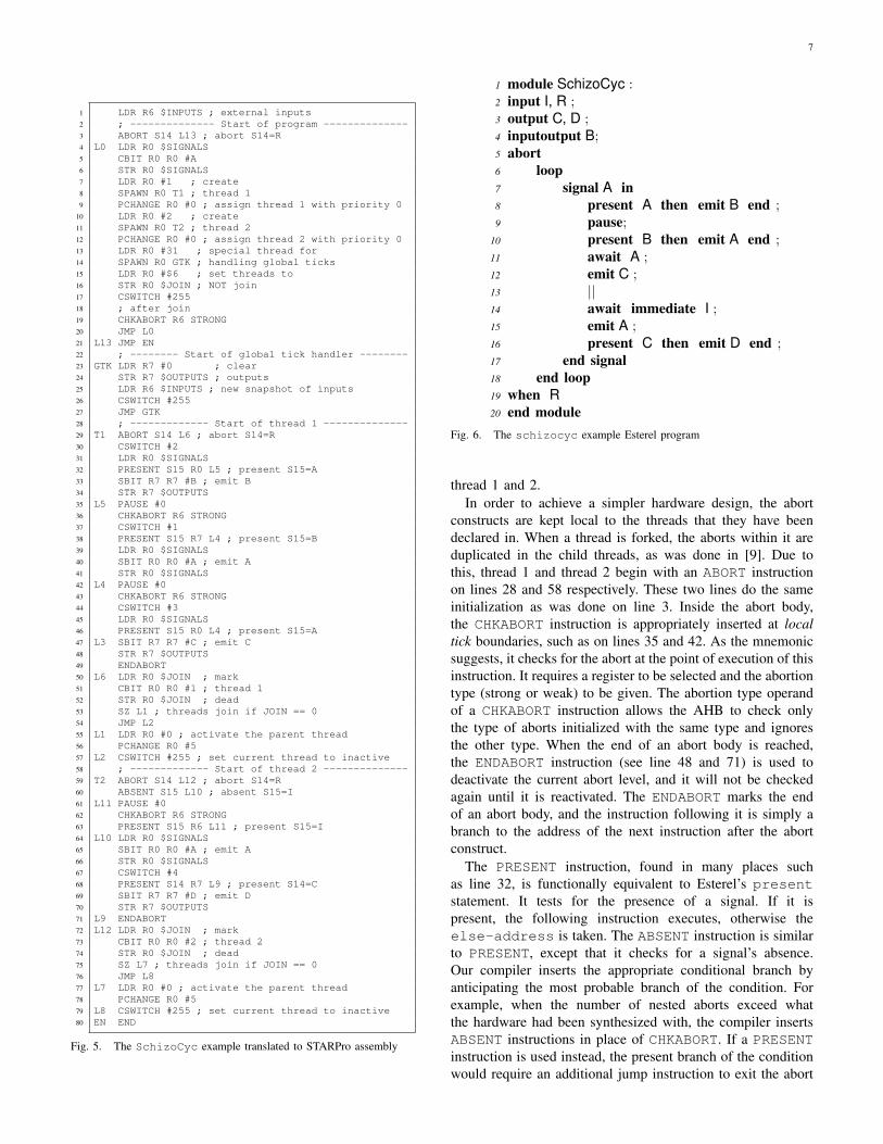
We illustrate the reactive instructions using the examplein Fig. 1. The equivalent STARPro assembly code for thatexample is shown in Fig. 5. For the reader’s convenience,Fig. 1 is replicated as Fig. 6 next to Fig. 5. We start byexplaining the reactive instructions used in this program, anddefer the discussion on the translation process to Section V.
Starting with ABORT on line 3, the first abort level isconfigured here to watch for signal 14 (signal R). Then, theprogram forks two concurrent threads. This is accomplishedusing the SPAWN instruction on lines 8 and 11, which createstwo new entries in the thread table of the TCB for thread 1and 2. These threads are then initialized to start at label T1and T2 respectively. Line 14 creates the special global tickmanagement thread. The PCHANGE instruction on lines 9and 12 set the initial priority of thread 1 and 2. Finally, theCSWITCH instruction on line 17 completes the thread-forkingprocess by setting the current (in this case, the root) threadinactive. The priority number of 255 is the lowest possiblepriority (indicating an inactive thread), while 0 is the highest.The CSWITCH instruction has two functions – it updates thepriority of the thread that executed it, and then, invokes thescheduler. The scheduler in response to CSWITCH, selectsa thread for resumption in the next instruction cycle. Sinceboth thread 1 and 2 have the same priority, the scheduler canrandomly select either thread for execution first. The PAUSEinstruction functions similarly to CSWITCH, but in addition,also marks the end of a local tick for the thread that executedit. PAUSE instructions can be found on several lines across
7
1 LDR R6 $INPUTS ; external inputs2 ; -------------- Start of program --------------3 ABORT S14 L13 ; abort S14=R4 L0 LDR R0 $SIGNALS5 CBIT R0 R0 #A6 STR R0 $SIGNALS7 LDR R0 #1 ; create8 SPAWN R0 T1 ; thread 19 PCHANGE R0 #0 ; assign thread 1 with priority 0
10 LDR R0 #2 ; create11 SPAWN R0 T2 ; thread 212 PCHANGE R0 #0 ; assign thread 2 with priority 013 LDR R0 #31 ; special thread for14 SPAWN R0 GTK ; handling global ticks15 LDR R0 #$6 ; set threads to16 STR R0 $JOIN ; NOT join17 CSWITCH #25518 ; after join19 CHKABORT R6 STRONG20 JMP L021 L13 JMP EN22 ; -------- Start of global tick handler --------23 GTK LDR R7 #0 ; clear24 STR R7 $OUTPUTS ; outputs25 LDR R6 $INPUTS ; new snapshot of inputs26 CSWITCH #25527 JMP GTK28 ; ------------- Start of thread 1 --------------29 T1 ABORT S14 L6 ; abort S14=R30 CSWITCH #231 LDR R0 $SIGNALS32 PRESENT S15 R0 L5 ; present S15=A33 SBIT R7 R7 #B ; emit B34 STR R7 $OUTPUTS35 L5 PAUSE #036 CHKABORT R6 STRONG37 CSWITCH #138 PRESENT S15 R7 L4 ; present S15=B39 LDR R0 $SIGNALS40 SBIT R0 R0 #A ; emit A41 STR R0 $SIGNALS42 L4 PAUSE #043 CHKABORT R6 STRONG44 CSWITCH #345 LDR R0 $SIGNALS46 PRESENT S15 R0 L4 ; present S15=A47 L3 SBIT R7 R7 #C ; emit C48 STR R7 $OUTPUTS49 ENDABORT50 L6 LDR R0 $JOIN ; mark51 CBIT R0 R0 #1 ; thread 152 STR R0 $JOIN ; dead53 SZ L1 ; threads join if JOIN == 054 JMP L255 L1 LDR R0 #0 ; activate the parent thread56 PCHANGE R0 #557 L2 CSWITCH #255 ; set current thread to inactive58 ; ------------- Start of thread 2 --------------59 T2 ABORT S14 L12 ; abort S14=R60 ABSENT S15 L10 ; absent S15=I61 L11 PAUSE #062 CHKABORT R6 STRONG63 PRESENT S15 R6 L11 ; present S15=I64 L10 LDR R0 $SIGNALS65 SBIT R0 R0 #A ; emit A66 STR R0 $SIGNALS67 CSWITCH #468 PRESENT S14 R7 L9 ; present S14=C69 SBIT R7 R7 #D ; emit D70 STR R7 $OUTPUTS71 L9 ENDABORT72 L12 LDR R0 $JOIN ; mark73 CBIT R0 R0 #2 ; thread 274 STR R0 $JOIN ; dead75 SZ L7 ; threads join if JOIN == 076 JMP L877 L7 LDR R0 #0 ; activate the parent thread78 PCHANGE R0 #579 L8 CSWITCH #255 ; set current thread to inactive80 EN END
Fig. 5. The SchizoCyc example translated to STARPro assembly
1 module SchizoCyc :2 input I, R ;3 output C, D ;4 inputoutput B;5 abort6 loop7 signal A in8 present A then emit B end ;9 pause;
10 present B then emit A end ;11 await A ;12 emit C ;13 ||14 await immediate I ;15 emit A ;16 present C then emit D end ;17 end signal18 end loop19 when R20 end module
Fig. 6. The schizocyc example Esterel program
thread 1 and 2.In order to achieve a simpler hardware design, the abort
constructs are kept local to the threads that they have beendeclared in. When a thread is forked, the aborts within it areduplicated in the child threads, as was done in [9]. Due tothis, thread 1 and thread 2 begin with an ABORT instructionon lines 28 and 58 respectively. These two lines do the sameinitialization as was done on line 3. Inside the abort body,the CHKABORT instruction is appropriately inserted at localtick boundaries, such as on lines 35 and 42. As the mnemonicsuggests, it checks for the abort at the point of execution of thisinstruction. It requires a register to be selected and the abortiontype (strong or weak) to be given. The abortion type operandof a CHKABORT instruction allows the AHB to check onlythe type of aborts initialized with the same type and ignoresthe other type. When the end of an abort body is reached,the ENDABORT instruction (see line 48 and 71) is used todeactivate the current abort level, and it will not be checkedagain until it is reactivated. The ENDABORT marks the endof an abort body, and the instruction following it is simply abranch to the address of the next instruction after the abortconstruct.
The PRESENT instruction, found in many places suchas line 32, is functionally equivalent to Esterel’s presentstatement. It tests for the presence of a signal. If it ispresent, the following instruction executes, otherwise theelse-address is taken. The ABSENT instruction is similarto PRESENT, except that it checks for a signal’s absence.Our compiler inserts the appropriate conditional branch byanticipating the most probable branch of the condition. Forexample, when the number of nested aborts exceed whatthe hardware had been synthesized with, the compiler insertsABSENT instructions in place of CHKABORT. If a PRESENTinstruction is used instead, the present branch of the conditionwould require an additional jump instruction to exit the abort
8
body, and to execute the abort handler. Also, whichever branchof the PRESENT instruction is taken, the processor pipelinewill be flushed, which reduces the performance benefit of thepipeline.
V. CODE GENERATION AND EXECUTION SEMANTICS
In order to generate assembly code from the Esterel source,the STARPro compiler uses an intermediate format, called theunrolled concurrent control-fow graph with surface and depth(UCCFGsd), to represent a given Esterel program. We firstpresent the UCCFGsd, and then, describe how assembly codeis generated from it.
A. Unrolled Concurrent Control-Flow Graph
The UCCFGsd is a variant of the UCCFG intermediateformat, which was first introduced in [9]. However, the UC-CFG is not capable of fully preserving Esterel’s semantics,especially for statements that have distinct start and resumptionbehaviours (also known as surface and depth behaviours),like that of the abort statement described in the exampleof Fig. 1. Some statements, like emit, are logically instan-taneous, while others, like the await statement, consumestime (ticks). Such non-instantaneous statements have distinctsurface and depth behaviours.
To overcome this, we have modified the original UCCFGformat, and extended it to explicitly capture both the surfaceand depth behaviour of every statement in Esterel. Thisapproach adapts the technique used in [7], where the start andresumption behaviours are differentiated using distinct surfacecode and depth code.
However, unlike [7], the control flow graph in our case is un-rolled due to explicit representation of the ticks. Moreover, wehave no explicit state encoding using state variables. Hence,our intermediate format is simpler and closely resembles theEsterel source.
In [7], each pass of the control-flow graph (CFG) representsan execution of just one tick. Thus, to compute the reaction formultiple ticks, the CFG would have to be executed within aloop. The selection of the appropriate surface and depth codein each pass of the graph is accomplished using state variables.In contrast, STARPro can directly preserve state informationduring execution through its PAUSE instruction, which es-sentially mimics Esterel’s pause statement by keeping theprogram counter for each thread unchanged until the start ofthe next tick.
In UCCFGsd, tick boundaries are marked by pause nodes,denoted as an arrow with a black bar on the right, as depictedin Fig. 11. Using these pause nodes, the loop required toexecute the CFG of [7] can be completely unrolled. Hence,instead of using a switch statement to select between thesurface and depth code as done in [7], code for STARProcan be conveniently represented in this form:
surface(code) followed by depth(code)
Using this approach, Esterel statements can be mapped toUCCFGsd nodes rather intuitively. The mapping of the abortstatement, however, would merit further elaboration.
B. Translating aborts
Translation of aborts is done in two stages: first, by markingthe start and end of the body, and subsequently, by placing thecheck abort node at the desired points. Depending on the typeof the abort, placement of the check abort nodes varies withrespect to the tick boundary. To handle the four types of aborts,we use the following general rules:• A strong abort always checks for preemption at the
start of a tick. Therefore, a check abort node is placedimmediately after each pause node.
• A weak abort always checks for preemption at theend of a tick. Therefore, a check abort node is placedimmediately before each pause node.
• The immediate version of a strong abort checks forpreemption before entering the abort body. A presentnode is simply added before the abort node to test forthe aborting condition.
• The non-immediate version of a weak abort also has thecheck abort nodes inserted before the pause node of thefirst instant. The reason for this is descibed below.
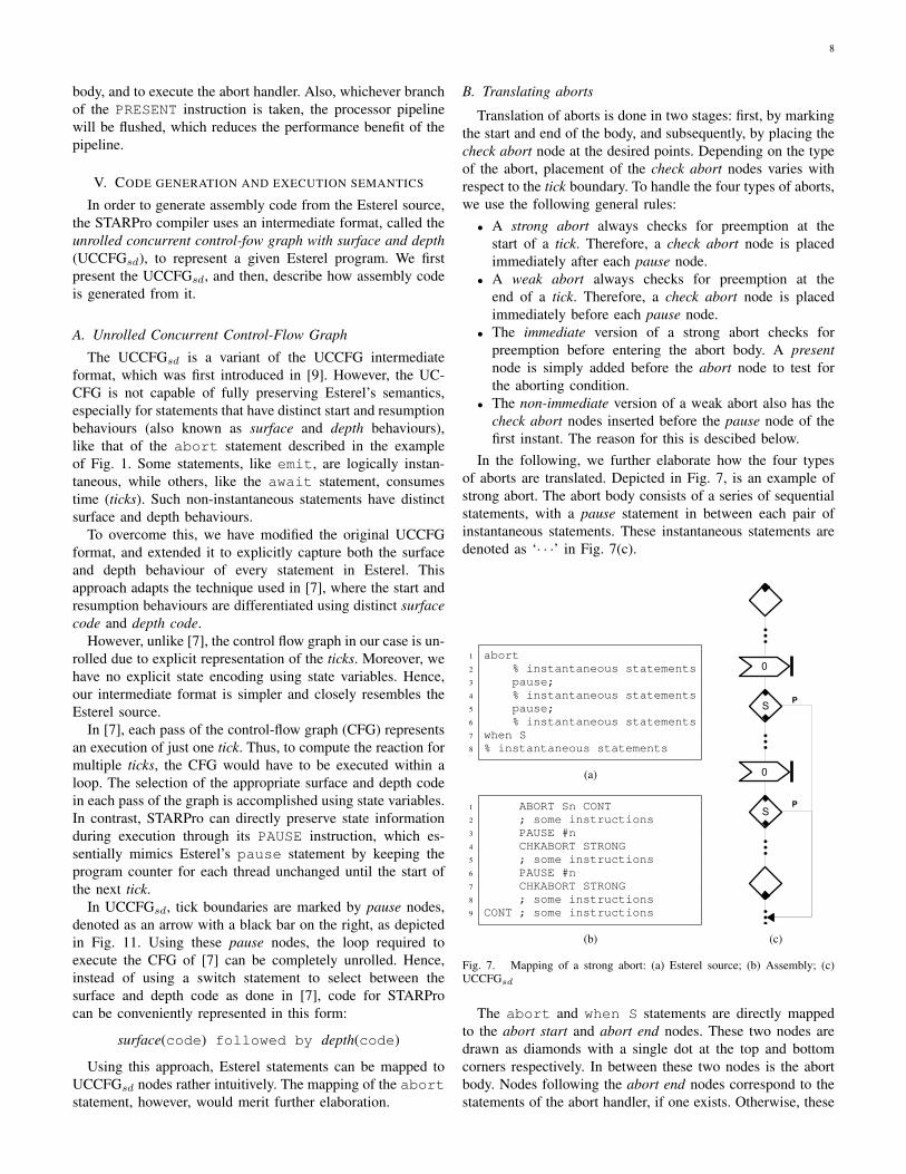
In the following, we further elaborate how the four typesof aborts are translated. Depicted in Fig. 7, is an example ofstrong abort. The abort body consists of a series of sequentialstatements, with a pause statement in between each pair ofinstantaneous statements. These instantaneous statements aredenoted as ‘· · ·’ in Fig. 7(c).
1 abort2 % instantaneous statements3 pause;4 % instantaneous statements5 pause;6 % instantaneous statements7 when S8 % instantaneous statements
(a)
1 ABORT Sn CONT2 ; some instructions3 PAUSE #n4 CHKABORT STRONG5 ; some instructions6 PAUSE #n7 CHKABORT STRONG8 ; some instructions9 CONT ; some instructions
(b)
S
0
0
S
P
P
(c)
Fig. 7. Mapping of a strong abort: (a) Esterel source; (b) Assembly; (c)UCCFGsd
The abort and when S statements are directly mappedto the abort start and abort end nodes. These two nodes aredrawn as diamonds with a single dot at the top and bottomcorners respectively. In between these two nodes is the abortbody. Nodes following the abort end nodes correspond to thestatements of the abort handler, if one exists. Otherwise, these
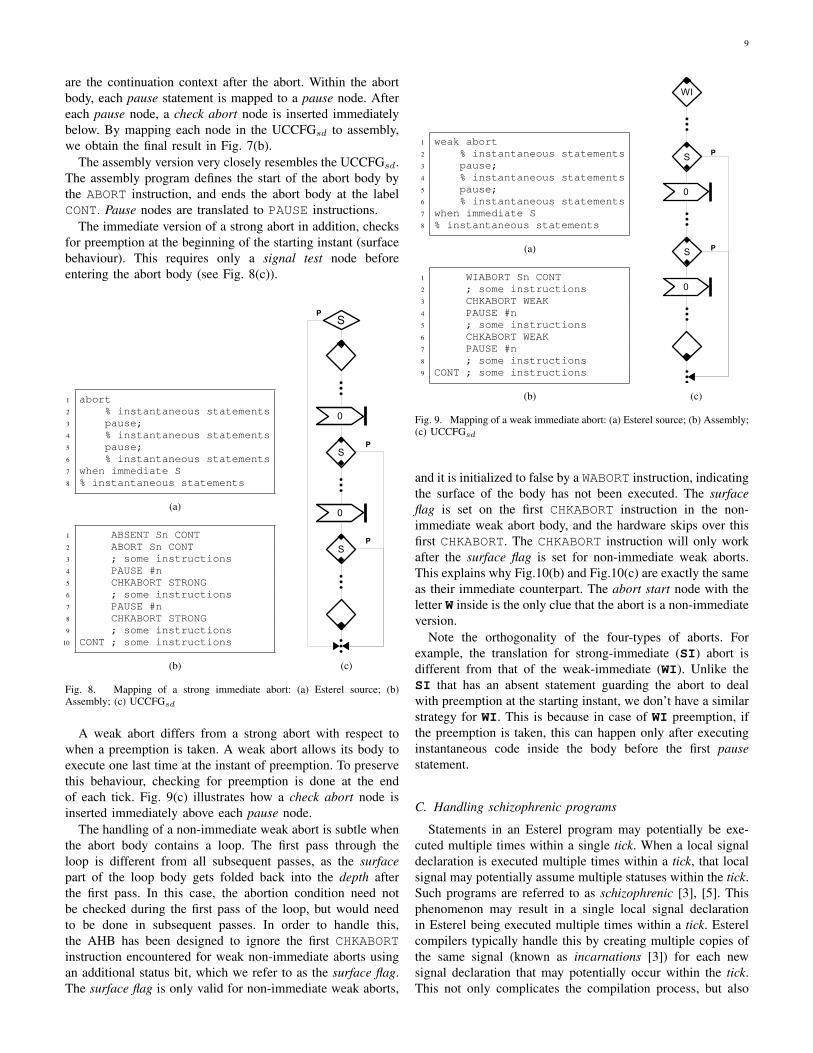
9
are the continuation context after the abort. Within the abortbody, each pause statement is mapped to a pause node. Aftereach pause node, a check abort node is inserted immediatelybelow. By mapping each node in the UCCFGsd to assembly,we obtain the final result in Fig. 7(b).
The assembly version very closely resembles the UCCFGsd.The assembly program defines the start of the abort body bythe ABORT instruction, and ends the abort body at the labelCONT. Pause nodes are translated to PAUSE instructions.
The immediate version of a strong abort in addition, checksfor preemption at the beginning of the starting instant (surfacebehaviour). This requires only a signal test node beforeentering the abort body (see Fig. 8(c)).
1 abort2 % instantaneous statements3 pause;4 % instantaneous statements5 pause;6 % instantaneous statements7 when immediate S8 % instantaneous statements
(a)
1 ABSENT Sn CONT2 ABORT Sn CONT3 ; some instructions4 PAUSE #n5 CHKABORT STRONG6 ; some instructions7 PAUSE #n8 CHKABORT STRONG9 ; some instructions
10 CONT ; some instructions
(b)
S
0
0
S
P
P
SP
(c)
Fig. 8. Mapping of a strong immediate abort: (a) Esterel source; (b)Assembly; (c) UCCFGsd
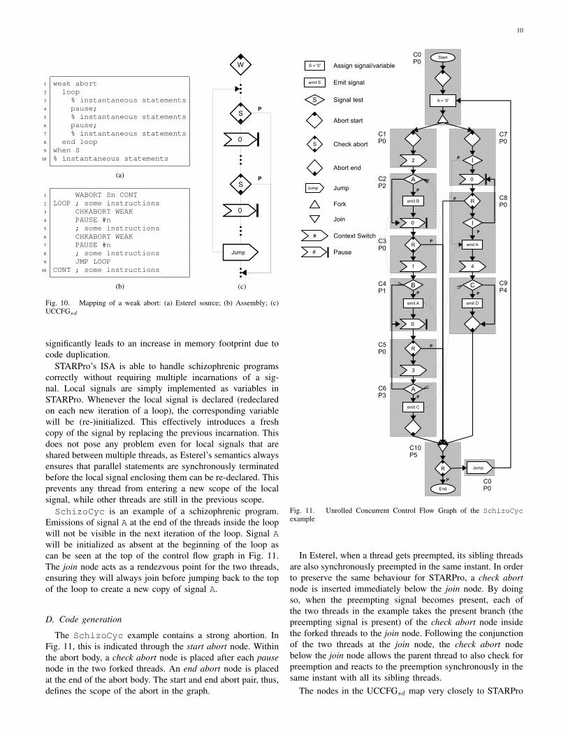
A weak abort differs from a strong abort with respect towhen a preemption is taken. A weak abort allows its body toexecute one last time at the instant of preemption. To preservethis behaviour, checking for preemption is done at the endof each tick. Fig. 9(c) illustrates how a check abort node isinserted immediately above each pause node.
The handling of a non-immediate weak abort is subtle whenthe abort body contains a loop. The first pass through theloop is different from all subsequent passes, as the surfacepart of the loop body gets folded back into the depth afterthe first pass. In this case, the abortion condition need notbe checked during the first pass of the loop, but would needto be done in subsequent passes. In order to handle this,the AHB has been designed to ignore the first CHKABORTinstruction encountered for weak non-immediate aborts usingan additional status bit, which we refer to as the surface flag.The surface flag is only valid for non-immediate weak aborts,
1 weak abort2 % instantaneous statements3 pause;4 % instantaneous statements5 pause;6 % instantaneous statements7 when immediate S8 % instantaneous statements
(a)
1 WIABORT Sn CONT2 ; some instructions3 CHKABORT WEAK4 PAUSE #n5 ; some instructions6 CHKABORT WEAK7 PAUSE #n8 ; some instructions9 CONT ; some instructions
(b)
S
WI
0
0
S
P
P
(c)
Fig. 9. Mapping of a weak immediate abort: (a) Esterel source; (b) Assembly;(c) UCCFGsd
and it is initialized to false by a WABORT instruction, indicatingthe surface of the body has not been executed. The surfaceflag is set on the first CHKABORT instruction in the non-immediate weak abort body, and the hardware skips over thisfirst CHKABORT. The CHKABORT instruction will only workafter the surface flag is set for non-immediate weak aborts.This explains why Fig.10(b) and Fig.10(c) are exactly the sameas their immediate counterpart. The abort start node with theletter W inside is the only clue that the abort is a non-immediateversion.
Note the orthogonality of the four-types of aborts. Forexample, the translation for strong-immediate (SI) abort isdifferent from that of the weak-immediate (WI). Unlike theSI that has an absent statement guarding the abort to dealwith preemption at the starting instant, we don’t have a similarstrategy for WI. This is because in case of WI preemption, ifthe preemption is taken, this can happen only after executinginstantaneous code inside the body before the first pausestatement.
C. Handling schizophrenic programs
Statements in an Esterel program may potentially be exe-cuted multiple times within a single tick. When a local signaldeclaration is executed multiple times within a tick, that localsignal may potentially assume multiple statuses within the tick.Such programs are referred to as schizophrenic [3], [5]. Thisphenomenon may result in a single local signal declarationin Esterel being executed multiple times within a tick. Esterelcompilers typically handle this by creating multiple copies ofthe same signal (known as incarnations [3]) for each newsignal declaration that may potentially occur within the tick.This not only complicates the compilation process, but also
10
1 weak abort2 loop3 % instantaneous statements4 pause;5 % instantaneous statements6 pause;7 % instantaneous statements8 end loop9 when S
10 % instantaneous statements
(a)
1 WABORT Sn CONT2 LOOP ; some instructions3 CHKABORT WEAK4 PAUSE #n5 ; some instructions6 CHKABORT WEAK7 PAUSE #n8 ; some instructions9 JMP LOOP
10 CONT ; some instructions
(b)
S
W
0
0
S
P
P
Jump
(c)
Fig. 10. Mapping of a weak abort: (a) Esterel source; (b) Assembly; (c)UCCFGsd
significantly leads to an increase in memory footprint due tocode duplication.
STARPro’s ISA is able to handle schizophrenic programscorrectly without requiring multiple incarnations of a sig-nal. Local signals are simply implemented as variables inSTARPro. Whenever the local signal is declared (redeclaredon each new iteration of a loop), the corresponding variablewill be (re-)initialized. This effectively introduces a freshcopy of the signal by replacing the previous incarnation. Thisdoes not pose any problem even for local signals that areshared between multiple threads, as Esterel’s semantics alwaysensures that parallel statements are synchronously terminatedbefore the local signal enclosing them can be re-declared. Thisprevents any thread from entering a new scope of the localsignal, while other threads are still in the previous scope.SchizoCyc is an example of a schizophrenic program.
Emissions of signal A at the end of the threads inside the loopwill not be visible in the next iteration of the loop. Signal Awill be initialized as absent at the beginning of the loop ascan be seen at the top of the control flow graph in Fig. 11.The join node acts as a rendezvous point for the two threads,ensuring they will always join before jumping back to the topof the loop to create a new copy of signal A.
D. Code generation
The SchizoCyc example contains a strong abortion. InFig. 11, this is indicated through the start abort node. Withinthe abort body, a check abort node is placed after each pausenode in the two forked threads. An end abort node is placedat the end of the abort body. The start and end abort pair, thus,defines the scope of the abort in the graph.
Start
A = '0'
0
R
3
A
emit C
2
0A
Remit B
I0
emit AR
41
CB
emit Demit A
R Jump
End
P
P
P
P
P
P
P
P
S = '0'
S
#
#
S
Jump
emit S
Assign signal/variable
Emit signal
Signal test
Abort start
Check abort
Abort end
Jump
Fork
Join
Context Switch
Pause
P
C0P0
C1P0
C2P2
C3P0
C4P1
C5P0
C6P3
C0P0
C7P0
C8P0
C9P4
C10P5
IP
Fig. 11. Unrolled Concurrent Control Flow Graph of the SchizoCycexample
In Esterel, when a thread gets preempted, its sibling threadsare also synchronously preempted in the same instant. In orderto preserve the same behaviour for STARPro, a check abortnode is inserted immediately below the join node. By doingso, when the preempting signal becomes present, each ofthe two threads in the example takes the present branch (thepreempting signal is present) of the check abort node insidethe forked threads to the join node. Following the conjunctionof the two threads at the join node, the check abort nodebelow the join node allows the parent thread to also check forpreemption and reacts to the preemption synchronously in thesame instant with all its sibling threads.
The nodes in the UCCFGsd map very closely to STARPro
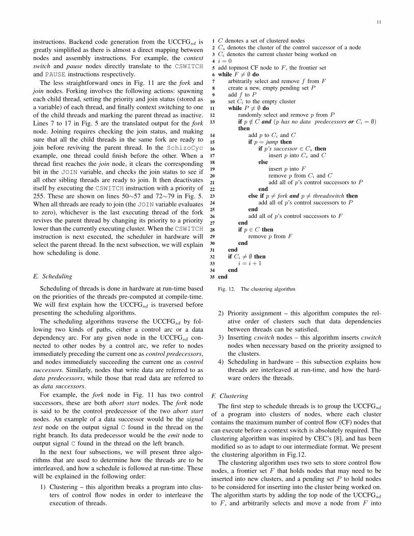
11
instructions. Backend code generation from the UCCFGsd isgreatly simplified as there is almost a direct mapping betweennodes and assembly instructions. For example, the contextswitch and pause nodes directly translate to the CSWITCHand PAUSE instructions respectively.
The less straightforward ones in Fig. 11 are the fork andjoin nodes. Forking involves the following actions: spawningeach child thread, setting the priority and join status (stored asa variable) of each thread, and finally context switching to oneof the child threads and marking the parent thread as inactive.Lines 7 to 17 in Fig. 5 are the translated output for the forknode. Joining requires checking the join status, and makingsure that all the child threads in the same fork are ready tojoin before reviving the parent thread. In the SchizoCycexample, one thread could finish before the other. When athread first reaches the join node, it clears the correspondingbit in the JOIN variable, and checks the join status to see ifall other sibling threads are ready to join. It then deactivatesitself by executing the CSWITCH instruction with a priority of255. These are shown on lines 50∼57 and 72∼79 in Fig. 5.When all threads are ready to join (the JOIN variable evaluatesto zero), whichever is the last executing thread of the forkrevives the parent thread by changing its priority to a prioritylower than the currently executing cluster. When the CSWITCHinstruction is next executed, the scheduler in hardware willselect the parent thread. In the next subsection, we will explainhow scheduling is done.
E. Scheduling
Scheduling of threads is done in hardware at run-time basedon the priorities of the threads pre-computed at compile-time.We will first explain how the UCCFGsd is traversed beforepresenting the scheduling algorithms.
The scheduling algorithms traverse the UCCFGsd by fol-lowing two kinds of paths, either a control arc or a datadependency arc. For any given node in the UCCFGsd con-nected to other nodes by a control arc, we refer to nodesimmediately preceding the current one as control predecessors,and nodes immediately succeeding the current one as controlsuccessors. Similarly, nodes that write data are referred to asdata predecessors, while those that read data are referred toas data successors.
For example, the fork node in Fig. 11 has two controlsuccessors, these are both abort start nodes. The fork nodeis said to be the control predecessor of the two abort startnodes. An example of a data successor would be the signaltest node on the output signal C found in the thread on theright branch. Its data predecessor would be the emit node tooutput signal C found in the thread on the left branch.
In the next four subsections, we will present three algo-rithms that are used to determine how the threads are to beinterleaved, and how a schedule is followed at run-time. Thesewill be explained in the following order:
1) Clustering – this algorithm breaks a program into clus-ters of control flow nodes in order to interleave theexecution of threads.
C denotes a set of clustered nodes1Cs denotes the cluster of the control successor of a node2Ci denotes the current cluster being worked on3i = 04add topmost CF node to F , the frontier set5while F 6= ∅ do6
arbitrarily select and remove f from F7create a new, empty pending set P8add f to P9set Ci to the empty cluster10while P 6= ∅ do11
randomly select and remove p from P12if p /∈ C and (p has no data predecessors or Ci = ∅)13then
add p to Ci and C14if p = jump then15
if p’s successor ∈ Cs then16insert p into Cs and C17
else18insert p into F19remove p from Ci and C20add all of p’s control successors to P21
end22else if p 6= fork and p 6= threadswitch then23
add all of p’s control successors to P24end25add all of p’s control successors to F26
end27if p ∈ C then28
remove p from F29end30
end31if Ci 6= ∅ then32
i = i + 133end34
end35
Fig. 12. The clustering algorithm
2) Priority assignment – this algorithm computes the rel-ative order of clusters such that data dependenciesbetween threads can be satisfied.
3) Inserting cswitch nodes – this algorithm inserts cswitchnodes when necessary based on the priority assigned tothe clusters.
4) Scheduling in hardware – this subsection explains howthreads are interleaved at run-time, and how the hard-ware orders the threads.
F. Clustering
The first step to schedule threads is to group the UCCFGsd
of a program into clusters of nodes, where each clustercontains the maximum number of control flow (CF) nodes thatcan execute before a context switch is absolutely required. Theclustering algorithm was inspired by CEC’s [8], and has beenmodified so as to adapt to our intermediate format. We presentthe clustering algorithm in Fig.12.
The clustering algorithm uses two sets to store control flownodes, a frontier set F that holds nodes that may need to beinserted into new clusters, and a pending set P to hold nodesto be considered for inserting into the cluster being worked on.The algorithm starts by adding the top node of the UCCFGsd
to F , and arbitrarily selects and move a node from F into
12
P . The outer loop creates a new cluster Ci everytime P isemptied by the inner loop, and the outer loop repeats until allthe nodes in the UCCFGsd have been clustered and F becomesempty.
Inside the inner loop, the algorithm first checks if the currentnode p has been clustered and that p has no data predecessor.However, node p can still be considered for clustering if thecurrent cluster Ci is empty. This is done on line 13 to ensurethat an unclustered node with data predecessors can be insertedinto a new empty cluster. For example, beginning at the top ofFig. 11, the start node is the first to be inserted into the firstcluster C0. Its control successor, the abort start node, is thenadded to P and F . A new successor is added to P and F oneach iteration of the inner loop until the fork node. The twocontrol successors of the fork node are the abort start nodes.These are inserted into F for clustering in a new cluster later.As soon as P is emptied, the outer loop restarts, creating anew cluster C1 and adding one of the abort start nodes to it.
Lines 15∼22 in the algorithm specially looks for jumpnodes, where a jump node is a node that unconditionally jumpsto some location in the program. It is used, for example, toimplement a loop. When a jump node leads to a node that hasa data predecessor, a cswitch node has to be inserted beforethe jump node. This means a jump node should be consideredas part of the cluster it is jumping to. The clustering algorithmachieves this by inserting jump nodes into set F , then add itssuccessor to P . This way, a jump node is always clusteredafter its control successor has been clustered. If a node p isnot a jump, and it is neither a fork nor a threadswitch (wherea threadswitch node is either a pause or cswitch), then all ofp’s control successors are added to set P .
G. Priority assignmentFollowing the clustering of all UCCFGsd nodes, priorities
are computed by statically analyzing the dependencies be-tween threads. The basic idea of the algorithm is to computepriority values of the clusters such that all signal producers willexecute before the consumers. This is achieved by determiningthe longest dependency chain for every cluster. The priority ofthe cluster at the start of the chain is the highest, while thatat the end of the chain is the lowest. All intermediate clustershave incrementally lower priority values. Such an algorithmrequires causal programs to compute these chains staticallyand will not work for non-causal programs. We can, however,generate correct code for programs with certain types of cyclicdependencies.
In Esterel, only non-instantaneous cyclic dependencies areallowed [3]. SchizoCyc is an example of this. It is alsopossible that an instantaneous cyclic dependency seeminglyexists in a program, but the dependency, in fact, does not existbecause at least one of the nodes in the cycle can never bereached in the same instant as the rest. An example of such aprogram is shown in Fig. 13. In this example, the first threadreacts to the presence of the input signal I on line 4, whilethe second thread reacts to the absence of I on line 8. SinceI can only be either present or absent at any instant, only oneof the statements on lines 5 and 9 can execute. Hence, thereare no dependencies between the two threads.
1 module InstCyc :2 input I ;3 output A, B ;4 present I then5 present A then emit B end ;6 end7 ||8 present I else9 present B then emit A end ;
10 end11 end module
Fig. 13. An example of a causal program with a false instantaneous cyclicdependency
foreach cluster C in the program do1traceDataPred(C)2
end3
function traceDataPred(C)1if C is visited then return priority of C2add C to the visited set3max depth = 04foreach CF node n in C do5
depth = 06foreach data predecessor p of n do7
if n = join then8n′ = first non-jump control predecessor of p9depth = traceDataPred(cluster of n′) +101if depth > max depth then11
max depth = depth12end13
else if p /∈ C then14depth = traceDataPred(cluster of n) +151if depth > max depth then16
max depth = depth17end18
end19end20
end21assign priority of C with max depth22return max depth23
end24
Fig. 14. The priority assignment algorithm
Given a causal program, if a dependency cycle is found,our compiler can still generate correct code. In such a case,the priority assignment assumes the program is causal, andan arbitrary cluster will be chosen as a starting point. Ourcompiler relies on existing tools [19] to do a priori causalityanalysis prior to compilation. This step is needed to ensurecorrect code generation using our compiler.
We present the priority assignment algorithm in Fig. 14. Thefirst two lines of the priority assignment algorithm do a depthfirst search along the data dependency arcs of each cluster,where tracing of the data dependency is done by the recursivefunction traceDataPred. Function traceDataPred im-mediately returns the priority of cluster C, the cluster beingtraced, if the cluster has already been assigned with a priority.This check on line 2 prevents the algorithm from deadlockingin a dependency cycle. For an unvisited cluster, it is, by default
13
C1 C2 C3
JumpJump
Jump
C4
n' n' n
S1 S2 S3
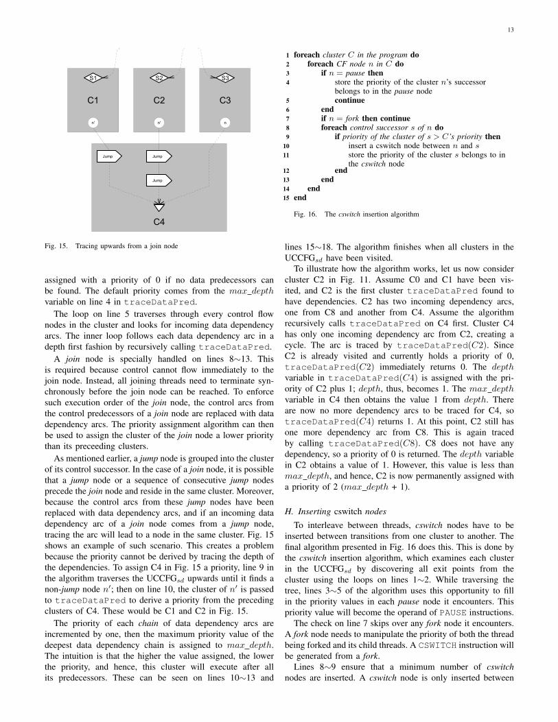
Fig. 15. Tracing upwards from a join node
assigned with a priority of 0 if no data predecessors canbe found. The default priority comes from the max depthvariable on line 4 in traceDataPred.
The loop on line 5 traverses through every control flownodes in the cluster and looks for incoming data dependencyarcs. The inner loop follows each data dependency arc in adepth first fashion by recursively calling traceDataPred.
A join node is specially handled on lines 8∼13. Thisis required because control cannot flow immediately to thejoin node. Instead, all joining threads need to terminate syn-chronously before the join node can be reached. To enforcesuch execution order of the join node, the control arcs fromthe control predecessors of a join node are replaced with datadependency arcs. The priority assignment algorithm can thenbe used to assign the cluster of the join node a lower prioritythan its preceeding clusters.
As mentioned earlier, a jump node is grouped into the clusterof its control successor. In the case of a join node, it is possiblethat a jump node or a sequence of consecutive jump nodesprecede the join node and reside in the same cluster. Moreover,because the control arcs from these jump nodes have beenreplaced with data dependency arcs, and if an incoming datadependency arc of a join node comes from a jump node,tracing the arc will lead to a node in the same cluster. Fig. 15shows an example of such scenario. This creates a problembecause the priority cannot be derived by tracing the depth ofthe dependencies. To assign C4 in Fig. 15 a priority, line 9 inthe algorithm traverses the UCCFGsd upwards until it finds anon-jump node n′; then on line 10, the cluster of n′ is passedto traceDataPred to derive a priority from the precedingclusters of C4. These would be C1 and C2 in Fig. 15.
The priority of each chain of data dependency arcs areincremented by one, then the maximum priority value of thedeepest data dependency chain is assigned to max depth.The intuition is that the higher the value assigned, the lowerthe priority, and hence, this cluster will execute after allits predecessors. These can be seen on lines 10∼13 and
foreach cluster C in the program do1foreach CF node n in C do2
if n = pause then3store the priority of the cluster n’s successor4belongs to in the pause nodecontinue5
end6if n = fork then continue7foreach control successor s of n do8
if priority of the cluster of s > C’s priority then9insert a cswitch node between n and s10store the priority of the cluster s belongs to in11the cswitch node
end12end13
end14end15
Fig. 16. The cswitch insertion algorithm
lines 15∼18. The algorithm finishes when all clusters in theUCCFGsd have been visited.
To illustrate how the algorithm works, let us now considercluster C2 in Fig. 11. Assume C0 and C1 have been vis-ited, and C2 is the first cluster traceDataPred found tohave dependencies. C2 has two incoming dependency arcs,one from C8 and another from C4. Assume the algorithmrecursively calls traceDataPred on C4 first. Cluster C4has only one incoming dependency arc from C2, creating acycle. The arc is traced by traceDataPred(C2). SinceC2 is already visited and currently holds a priority of 0,traceDataPred(C2) immediately returns 0. The depthvariable in traceDataPred(C4) is assigned with the pri-ority of C2 plus 1; depth, thus, becomes 1. The max depthvariable in C4 then obtains the value 1 from depth. Thereare now no more dependency arcs to be traced for C4, sotraceDataPred(C4) returns 1. At this point, C2 still hasone more dependency arc from C8. This is again tracedby calling traceDataPred(C8). C8 does not have anydependency, so a priority of 0 is returned. The depth variablein C2 obtains a value of 1. However, this value is less thanmax depth, and hence, C2 is now permanently assigned witha priority of 2 (max depth + 1).
H. Inserting cswitch nodes
To interleave between threads, cswitch nodes have to beinserted between transitions from one cluster to another. Thefinal algorithm presented in Fig. 16 does this. This is done bythe cswitch insertion algorithm, which examines each clusterin the UCCFGsd by discovering all exit points from thecluster using the loops on lines 1∼2. While traversing thetree, lines 3∼5 of the algorithm uses this opportunity to fillin the priority values in each pause node it encounters. Thispriority value will become the operand of PAUSE instructions.
The check on line 7 skips over any fork node it encounters.A fork node needs to manipulate the priority of both the threadbeing forked and its child threads. A CSWITCH instruction willbe generated from a fork.
Lines 8∼9 ensure that a minimum number of cswitchnodes are inserted. A cswitch node is only inserted between
14
a transition from a cluster with a priority value that is lowerthan its successor cluster. Clusters that depend on each otherare maintained in this relative order – signal producers aregiven a chance to execute before consumer clusters execute.Conversely, a cswitch node is not necessary, as the lowerpriority value of the succeeding cluster means either thedependency has already been satisfied prior to the currentexecuting cluster, or there are no data dependencies betweenthese two clusters. Finally, line 11 stores the priority of thesucceeding cluster in each cswitch node.
We will again use Fig. 11 to illustrate how cswitch nodesare inserted by the algorithm. Starting with the first cluster C0,it has two exit points from fork. Exit points from a fork nodeare skipped by the algorithm. The next cluster C1 visited bythe algorithm has one exit point to C2. The transition from C1to C2 is a transition from a higher priorty cluster to that of alower one (from P0 to P2). A cswitch is inserted before C2 togive any potential signal emitters a chance to execute prior toC2. The newly inserted cswitch node has a priority value of2 stored in it, where the value comes from the priority of C2.Moving on to the next cluster C2, the pause node in C2 isassigned with the priority of C3. One thing that Fig. 11 doesnot show is that the control arcs leading to the join node haveactually been replaced with data dependency arcs. Becauseof this change, the algorithm does not find exit points fromclusters that previously had control arcs to join. Hence, nocswitch is inserted, and instead, context switching and revivingof the parent thread is handled by the join node.
I. Scheduling in hardware
The priority of a thread is changed by executing thePCHANGE, CSWITCH or PAUSE instruction. The schedulerkeeps the priority of all threads in the TCB. The highestpriority is 0, while the number 255 is reserved as an indicationthat the thread is inactive. The scheduler also stores thelocal tick status flags of every thread. The scheduler makesa decision on which thread to select when a CSWITCH orPAUSE instruction is executed. The decision is made basedon the following steps in the given order:
1) Limit the selection to active (priority < 255) threadsonly.
2) Limit the selection to threads whose local tick statusevaluates to false.
3) Select the thread with the highest priority (lowest num-ber).
4) When no more threads can be selected, the special globaltick handler thread is selected and the local tick flags ofevery thread are reset to false. This completes the globaltick.
The last step described above is only performed at the endof a global tick, which can only be reached when the localtick status flags of all active threads evaluate to true. At theend of each global tick, all signal outputs to the environmentand local signals need to be reset. A new snapshot of inputsfrom the environment needs to be taken. STARPro relies onsoftware code to manipulate memory mapped I/O, using aspecial thread, called the global tick handler. The scheduler
selects this thread when step 4) is performed. However, as asingle threaded program does not rely on a special global tickhandler, the code of the global tick handler is simply generatedfor the pause nodes instead.
To illustrate how SchizoCyc executes on STARPro, weshow the same assembly code in Fig. 17(a) with commentsremoved. On the right, Fig. 17(b) shows the changes of thevalues of the program counter, local tick status flag, and thepriority of each thread.
In the starting instant of the program, the root thread startsforking into two threads. The global tick handler thread getscreated after line 12, while thread 1 and 2 are created online 6 and 9 respectively. All threads except the root thread areinitialized to a priority of 255 upon start up of the processor.The root thread starts with a priority of 0. During the forkingprocess, the priorities of the threads are re-assigned by thePCHANGE instruction, as can be seen in the table at the topof Fig. 17(b). We show signals that are present in the currenttick in the top right hand corner of the thread context table.
Shortly after creating threads, the newly created threads areready to be scheduled by executing the CSWITCH instructionon line 15. The second table below shows the thread contextafter the fork. The root thread becomes inactive at this pointwith the priority set to 255. This makes the priority of theparent thread 255 (lowest possible) and passes control to thescheduler. The program counter will be frozen at 16 until thethread is resumed. The same applies to all other threads thatare suspended through context switches.
Continuing on, since both thread 1 and 2 have the samepriority, it does not matter which one is executed first. Ifthread 1 is selected, it quickly reaches another context switchon line 25. Looking at the third table from the top, theinstruction on line 25 lowered the priority of thread 1 to 1,while thread 2’s priority is now higher at 0. Both thread 1 and2 have not completed their local ticks and are still active, thusboth are valid candidates to be scheduled next. Since thread 2now has higher priority it is selected for execution.
The fourth table shows the result after executing thread 2up to the first PAUSE instruction on line 55, assuming inputsignal I is absent in the first instant. PAUSE sets the local tickstatus flag of thread 2 to true, and refreshes its priority with0. Thread 2 is no longer a candidate for scheduling, leavingthread 1 as the only active thread 1 yet to complete its localtick. Similarly, we arrive with the results in the next table aftercompleting the remainder of the tick in thread 1. No morethreads can now be scheduled as thread 0 is inactive, whilethread 1 and 2 have both completed their local ticks. Thistriggers a global tick signal internal to the scheduler, whichcauses the global tick handler thread to be scheduled. Becauseof the special role of the global tick handler, and since it playsno part in the scheduling of threads, it has no priority.
Tick 1 starts after executing the CSWITCH instruction online 22. Note the local tick status flags have been reset tofalse. The flow of the execution carries on in similar fashionas described above.
In a different scenario, an interesting case arises whenthe input signal I is present in the first instant. Thread 2would finish before thread 1 in this case. The code between
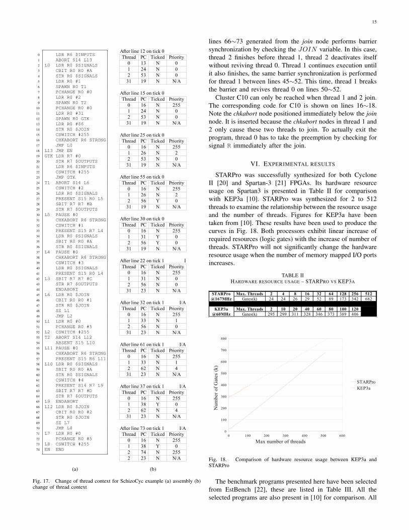
15
0 LDR R6 $INPUTS1 ABORT S14 L132 L0 LDR R0 $SIGNALS3 CBIT R0 R0 #A4 STR R0 $SIGNALS5 LDR R0 #16 SPAWN R0 T17 PCHANGE R0 #08 LDR R0 #29 SPAWN R0 T2
10 PCHANGE R0 #011 LDR R0 #3112 SPAWN R0 GTK13 LDR R0 #$614 STR R0 $JOIN15 CSWITCH #25516 CHKABORT R6 STRONG17 JMP L018 L13 JMP EN19 GTK LDR R7 #020 STR R7 $OUTPUTS21 LDR R6 $INPUTS22 CSWITCH #25523 JMP GTK24 T1 ABORT S14 L625 CSWITCH #226 LDR R0 $SIGNALS27 PRESENT S15 R0 L528 SBIT R7 R7 #B29 STR R7 $OUTPUTS30 L5 PAUSE #031 CHKABORT R6 STRONG32 CSWITCH #133 PRESENT S15 R7 L434 LDR R0 $SIGNALS35 SBIT R0 R0 #A36 STR R0 $SIGNALS37 L4 PAUSE #038 CHKABORT R6 STRONG39 CSWITCH #340 LDR R0 $SIGNALS41 PRESENT S15 R0 L442 L3 SBIT R7 R7 #C43 STR R7 $OUTPUTS44 ENDABORT45 L6 LDR R0 $JOIN46 CBIT R0 R0 #147 STR R0 $JOIN48 SZ L149 JMP L250 L1 LDR R0 #051 PCHANGE R0 #552 L2 CSWITCH #25553 T2 ABORT S14 L1254 ABSENT S15 L1055 L11 PAUSE #056 CHKABORT R6 STRONG57 PRESENT S15 R6 L1158 L10 LDR R0 $SIGNALS59 SBIT R0 R0 #A60 STR R0 $SIGNALS61 CSWITCH #462 PRESENT S14 R7 L963 SBIT R7 R7 #D64 STR R7 $OUTPUTS65 L9 ENDABORT66 L12 LDR R0 $JOIN67 CBIT R0 R0 #268 STR R0 $JOIN69 SZ L770 JMP L871 L7 LDR R0 #072 PCHANGE R0 #573 L8 CSWITCH #25574 EN END
(a)
After line 12 on tick 0Thread PC Ticked Priority
0 13 N 01 24 N 02 53 N 0
31 19 N N/A
After line 15 on tick 0Thread PC Ticked Priority
0 16 N 2551 24 N 02 53 N 0
31 19 N N/A
After line 25 on tick 0Thread PC Ticked Priority
0 16 N 2551 26 N 22 53 N 0
31 19 N N/A
After line 55 on tick 0Thread PC Ticked Priority
0 16 N 2551 26 N 22 56 Y 0
31 19 N N/A
After line 30 on tick 0Thread PC Ticked Priority
0 16 N 2551 31 Y 02 56 Y 0
31 19 N N/A
After line 22 on tick 1 IThread PC Ticked Priority
0 16 N 2551 31 N 02 56 N 0
31 23 N N/A
After line 32 on tick 1 I/AThread PC Ticked Priority
0 16 N 2551 33 N 12 56 N 0
31 23 N N/A
After line 61 on tick 1 I/AThread PC Ticked Priority
0 16 N 2551 33 N 12 62 N 4
31 23 N N/A
After line 37 on tick 1 I/AThread PC Ticked Priority
0 16 N 2551 38 Y 02 62 N 4
31 23 N N/A
After line 73 on tick 1 I/AThread PC Ticked Priority
0 16 N 2551 38 Y 02 74 N 2552 23 N N/A
(b)
Fig. 17. Change of thread context for SchizoCyc example (a) assembly (b)change of thread context
lines 66∼73 generated from the join node performs barriersynchronization by checking the JOIN variable. In this case,thread 2 finishes before thread 1, thread 2 deactivates itselfwithout reviving thread 0. Thread 1 continues execution untilit also finishes, the same barrier synchronization is performedfor thread 1 between lines 45∼52. This time, thread 1 breaksthe barrier and revives thread 0 on lines 50∼52.
Cluster C10 can only be reached when thread 1 and 2 join.The corresponding code for C10 is shown on lines 16∼18.Note the chkabort node positioned immediately below the joinnode. It is inserted because the chkabort nodes in thread 1 and2 only cause these two threads to join. To actually exit theprogram, thread 0 has to take the preemption by checking forsignal R immediately after the join.
VI. EXPERIMENTAL RESULTS
STARPro was successfully synthesized for both CycloneII [20] and Spartan-3 [21] FPGAs. Its hardware resourceusage on Spartan3 is presented in Table II for comparisonwith KEP3a [10]. STARPro was synthesized for 2 to 512threads to examine the relationship between the resource usageand the number of threads. Figures for KEP3a have beentaken from [10]. These results have been used to produce thecurves in Fig. 18. Both processors exhibit linear increase ofrequired resources (logic gates) with the increase of number ofthreads. STARPro will not significantly change the hardwareresource usage when the number of memory mapped I/O portsincreases.
TABLE IIHARDWARE RESOURCE USAGE – STARPRO VS KEP3A
STARPro Max. Threads 2 4 8 16 32 64 128 256 512@167MHz Gates(k) 24 24 26 29 52 89 173 342 682
KEP3a Max. Threads 2 10 20 40 60 80 100 120@60MHz Gates(k) 295 299 311 328 346 373 389 406
0 100 200 300 400 500 6000
100
200
300
400
500
600
700
800
STARProKEP3aLinear Regression for KEP3a
Max number of threads
Num
ber
of G
ates
(k)
Fig. 18. Comparison of hardware resource usage between KEP3a andSTARPro
The benchmark programs presented here have been selectedfrom EstBench [22], these are listed in Table III. All theselected programs are also present in [10] for comparison. All
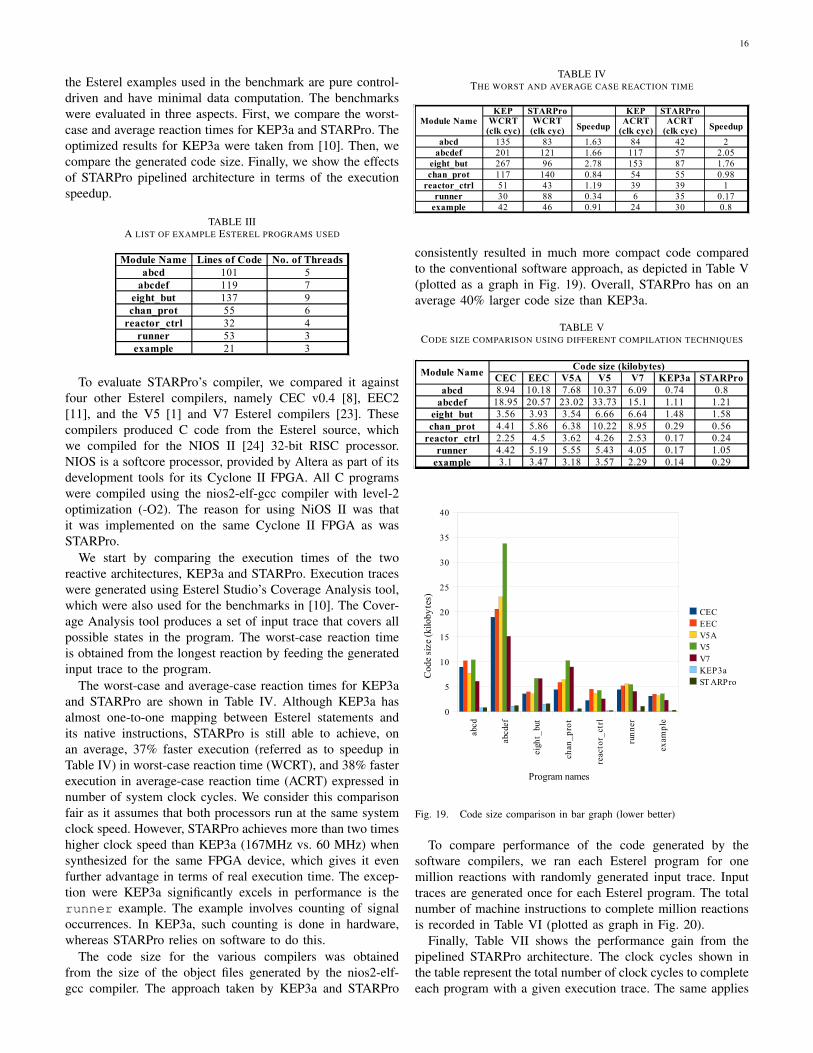
16
the Esterel examples used in the benchmark are pure control-driven and have minimal data computation. The benchmarkswere evaluated in three aspects. First, we compare the worst-case and average reaction times for KEP3a and STARPro. Theoptimized results for KEP3a were taken from [10]. Then, wecompare the generated code size. Finally, we show the effectsof STARPro pipelined architecture in terms of the executionspeedup.
TABLE IIIA LIST OF EXAMPLE ESTEREL PROGRAMS USED
Module Name Lines of Code No. of Threadsabcd 101 5
abcdef 119 7eight_but 137 9chan_prot 55 6
reactor_ctrl 32 4runner 53 3
example 21 3
To evaluate STARPro’s compiler, we compared it againstfour other Esterel compilers, namely CEC v0.4 [8], EEC2[11], and the V5 [1] and V7 Esterel compilers [23]. Thesecompilers produced C code from the Esterel source, whichwe compiled for the NIOS II [24] 32-bit RISC processor.NIOS is a softcore processor, provided by Altera as part of itsdevelopment tools for its Cyclone II FPGA. All C programswere compiled using the nios2-elf-gcc compiler with level-2optimization (-O2). The reason for using NiOS II was thatit was implemented on the same Cyclone II FPGA as wasSTARPro.
We start by comparing the execution times of the tworeactive architectures, KEP3a and STARPro. Execution traceswere generated using Esterel Studio’s Coverage Analysis tool,which were also used for the benchmarks in [10]. The Cover-age Analysis tool produces a set of input trace that covers allpossible states in the program. The worst-case reaction timeis obtained from the longest reaction by feeding the generatedinput trace to the program.
The worst-case and average-case reaction times for KEP3aand STARPro are shown in Table IV. Although KEP3a hasalmost one-to-one mapping between Esterel statements andits native instructions, STARPro is still able to achieve, onan average, 37% faster execution (referred as to speedup inTable IV) in worst-case reaction time (WCRT), and 38% fasterexecution in average-case reaction time (ACRT) expressed innumber of system clock cycles. We consider this comparisonfair as it assumes that both processors run at the same systemclock speed. However, STARPro achieves more than two timeshigher clock speed than KEP3a (167MHz vs. 60 MHz) whensynthesized for the same FPGA device, which gives it evenfurther advantage in terms of real execution time. The excep-tion were KEP3a significantly excels in performance is therunner example. The example involves counting of signaloccurrences. In KEP3a, such counting is done in hardware,whereas STARPro relies on software to do this.
The code size for the various compilers was obtainedfrom the size of the object files generated by the nios2-elf-gcc compiler. The approach taken by KEP3a and STARPro
TABLE IVTHE WORST AND AVERAGE CASE REACTION TIME
Module NameKEP STARPro KEP STARPro
Speedup Speedup
abcd 135 83 1.63 84 42 2abcdef 201 121 1.66 117 57 2.05
eight_but 267 96 2.78 153 87 1.76chan_prot 117 140 0.84 54 55 0.98
reactor_ctrl 51 43 1.19 39 39 1runner 30 88 0.34 6 35 0.17
example 42 46 0.91 24 30 0.8
WCRT(clk cyc)
WCRT(clk cyc)
ACRT(clk cyc)
ACRT(clk cyc)
consistently resulted in much more compact code comparedto the conventional software approach, as depicted in Table V(plotted as a graph in Fig. 19). Overall, STARPro has on anaverage 40% larger code size than KEP3a.
TABLE VCODE SIZE COMPARISON USING DIFFERENT COMPILATION TECHNIQUES
Module NameCode size (kilobytes)
CEC EEC V5A V5 V7 KEP3a STARProabcd 8.94 10.18 7.68 10.37 6.09 0.74 0.8
abcdef 18.95 20.57 23.02 33.73 15.1 1.11 1.21eight_but 3.56 3.93 3.54 6.66 6.64 1.48 1.58chan_prot 4.41 5.86 6.38 10.22 8.95 0.29 0.56
reactor_ctrl 2.25 4.5 3.62 4.26 2.53 0.17 0.24runner 4.42 5.19 5.55 5.43 4.05 0.17 1.05
example 3.1 3.47 3.18 3.57 2.29 0.14 0.29ab
cd
abcd
ef
eigh
t_bu
t
chan
_p
rot
reac
tor_
ctrl
run
ner
exam
ple
0
5
10
15
20
25
30
35
40
CECEECV5AV5V7KEP3aST ARPro
Program names
Cod
e si
ze (
kilo
byte
s)
Fig. 19. Code size comparison in bar graph (lower better)
To compare performance of the code generated by thesoftware compilers, we ran each Esterel program for onemillion reactions with randomly generated input trace. Inputtraces are generated once for each Esterel program. The totalnumber of machine instructions to complete million reactionsis recorded in Table VI (plotted as graph in Fig. 20).
Finally, Table VII shows the performance gain from thepipelined STARPro architecture. The clock cycles shown inthe table represent the total number of clock cycles to completeeach program with a given execution trace. The same applies
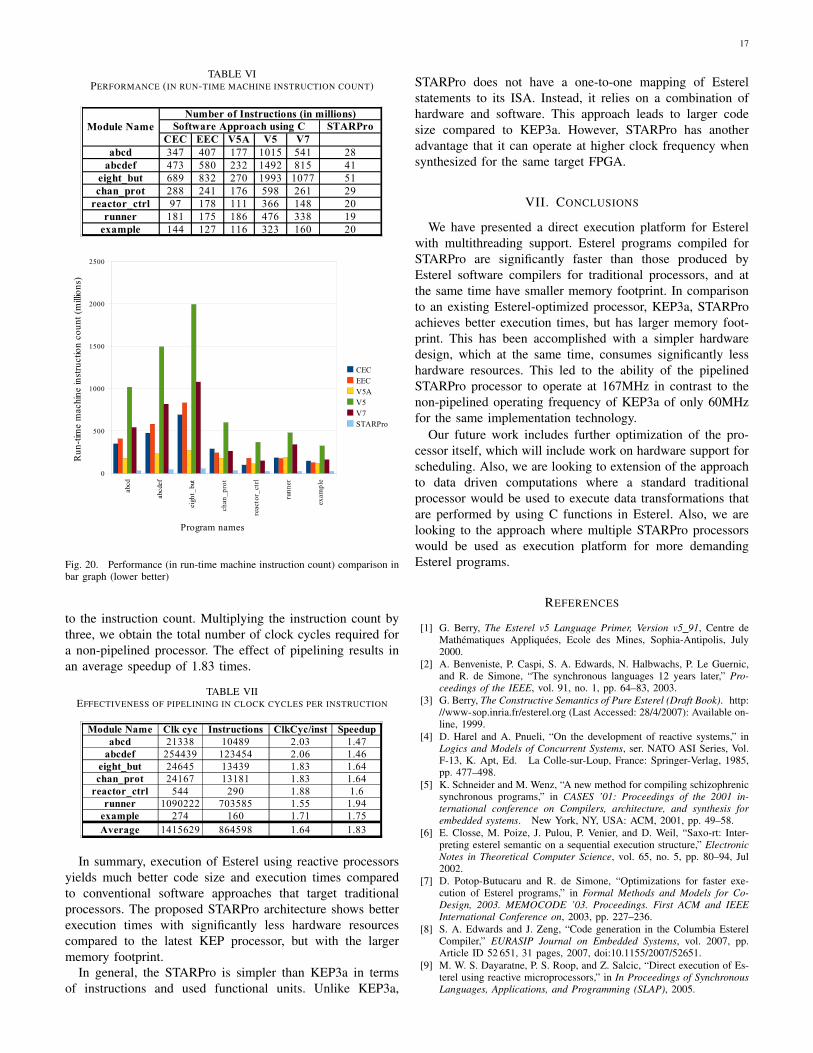
17
TABLE VIPERFORMANCE (IN RUN-TIME MACHINE INSTRUCTION COUNT)
Module NameNumber of Instructions (in millions)
Software Approach using C STARProCEC EEC V5A V5 V7
abcd 347 407 177 1015 541 28abcdef 473 580 232 1492 815 41
eight_but 689 832 270 1993 1077 51chan_prot 288 241 176 598 261 29
reactor_ctrl 97 178 111 366 148 20runner 181 175 186 476 338 19
example 144 127 116 323 160 20
abcd
abcd
ef
eigh
t_bu
t
chan
_p
rot
reac
tor_
ctrl
run
ner
exam
ple
0
500
1000
1500
2000
2500
CECEECV5AV5V7STARPro
Program names
Run
-tim
e m
achi
ne in
stru
ctio
n co
unt (
mill
ions
)
Fig. 20. Performance (in run-time machine instruction count) comparison inbar graph (lower better)
to the instruction count. Multiplying the instruction count bythree, we obtain the total number of clock cycles required fora non-pipelined processor. The effect of pipelining results inan average speedup of 1.83 times.
TABLE VIIEFFECTIVENESS OF PIPELINING IN CLOCK CYCLES PER INSTRUCTION
Module Name Clk cyc Instructions ClkCyc/inst Speedupabcd 21338 10489 2.03 1.47
abcdef 254439 123454 2.06 1.46eight_but 24645 13439 1.83 1.64chan_prot 24167 13181 1.83 1.64
reactor_ctrl 544 290 1.88 1.6runner 1090222 703585 1.55 1.94
example 274 160 1.71 1.75Average 1415629 864598 1.64 1.83
In summary, execution of Esterel using reactive processorsyields much better code size and execution times comparedto conventional software approaches that target traditionalprocessors. The proposed STARPro architecture shows betterexecution times with significantly less hardware resourcescompared to the latest KEP processor, but with the largermemory footprint.
In general, the STARPro is simpler than KEP3a in termsof instructions and used functional units. Unlike KEP3a,
STARPro does not have a one-to-one mapping of Esterelstatements to its ISA. Instead, it relies on a combination ofhardware and software. This approach leads to larger codesize compared to KEP3a. However, STARPro has anotheradvantage that it can operate at higher clock frequency whensynthesized for the same target FPGA.
VII. CONCLUSIONS
We have presented a direct execution platform for Esterelwith multithreading support. Esterel programs compiled forSTARPro are significantly faster than those produced byEsterel software compilers for traditional processors, and atthe same time have smaller memory footprint. In comparisonto an existing Esterel-optimized processor, KEP3a, STARProachieves better execution times, but has larger memory foot-print. This has been accomplished with a simpler hardwaredesign, which at the same time, consumes significantly lesshardware resources. This led to the ability of the pipelinedSTARPro processor to operate at 167MHz in contrast to thenon-pipelined operating frequency of KEP3a of only 60MHzfor the same implementation technology.
Our future work includes further optimization of the pro-cessor itself, which will include work on hardware support forscheduling. Also, we are looking to extension of the approachto data driven computations where a standard traditionalprocessor would be used to execute data transformations thatare performed by using C functions in Esterel. Also, we arelooking to the approach where multiple STARPro processorswould be used as execution platform for more demandingEsterel programs.
REFERENCES
[1] G. Berry, The Esterel v5 Language Primer, Version v5 91, Centre deMathematiques Appliquees, Ecole des Mines, Sophia-Antipolis, July2000.
[2] A. Benveniste, P. Caspi, S. A. Edwards, N. Halbwachs, P. Le Guernic,and R. de Simone, “The synchronous languages 12 years later,” Pro-ceedings of the IEEE, vol. 91, no. 1, pp. 64–83, 2003.
[3] G. Berry, The Constructive Semantics of Pure Esterel (Draft Book). http://www-sop.inria.fr/esterel.org (Last Accessed: 28/4/2007): Available on-line, 1999.
[4] D. Harel and A. Pnueli, “On the development of reactive systems,” inLogics and Models of Concurrent Systems, ser. NATO ASI Series, Vol.F-13, K. Apt, Ed. La Colle-sur-Loup, France: Springer-Verlag, 1985,pp. 477–498.
[5] K. Schneider and M. Wenz, “A new method for compiling schizophrenicsynchronous programs,” in CASES ’01: Proceedings of the 2001 in-ternational conference on Compilers, architecture, and synthesis forembedded systems. New York, NY, USA: ACM, 2001, pp. 49–58.
[6] E. Closse, M. Poize, J. Pulou, P. Venier, and D. Weil, “Saxo-rt: Inter-preting esterel semantic on a sequential execution structure,” ElectronicNotes in Theoretical Computer Science, vol. 65, no. 5, pp. 80–94, Jul2002.
[7] D. Potop-Butucaru and R. de Simone, “Optimizations for faster exe-cution of Esterel programs,” in Formal Methods and Models for Co-Design, 2003. MEMOCODE ’03. Proceedings. First ACM and IEEEInternational Conference on, 2003, pp. 227–236.
[8] S. A. Edwards and J. Zeng, “Code generation in the Columbia EsterelCompiler,” EURASIP Journal on Embedded Systems, vol. 2007, pp.Article ID 52 651, 31 pages, 2007, doi:10.1155/2007/52651.
[9] M. W. S. Dayaratne, P. S. Roop, and Z. Salcic, “Direct execution of Es-terel using reactive microprocessors,” in In Proceedings of SynchronousLanguages, Applications, and Programming (SLAP), 2005.
18
[10] X. Li, M. Boldt, and R. von Hanxleden, “Mapping Esterel onto a multi-threaded embedded processor,” in Proceedings of the 12th InternationalConference on Architectural Support for Programming Languages andOperating Systems (ASPLOS’06), San Jose, CA, October 21–25 2006.
[11] L. H. Yoong, P. Roop, Z. Salcic, and F. Gruian, “Compiling Esterelfor distributed execution,” in International Workshop on SynchronousLanguages, Applications, and Programming (SLAP’06), Vienna, Austria,March 2006.
[12] X. Li and R. von Hanxleden, “The Kiel Esterel Processor - a semi-custom, configurable reactive processor,” in Synchronous Programming- SYNCHRON’04, ser. Dagstuhl Seminar Proceedings, S. A. Edwards,N. Halbwachs, R. v. Hanxleden, and T. Stauner, Eds., no. 04491.Internationales Begegnungs- und Forschungszentrum (IBFI), SchlossDagstuhl, Germany, 2005.
[13] X. Li, J. Lukoschus, M. Boldt, M. Harder, and R. von Hanxleden, “AnEsterel processor with full preemption support and its worst case reactiontime analysis,” in CASES ’05: Proceedings of the 2005 internationalconference on Compilers, architectures and synthesis for embeddedsystems. New York, NY, USA: ACM Press, 2005, pp. 225–236.
[14] X. Li and R. von Hanxleden, “A concurrent reactive Esterel processorbased on multi-threading,” in SAC ’06: Proceedings of the 2006 ACMsymposium on Applied computing. New York, NY, USA: ACM Press,2006, pp. 912–917.
[15] S. Yuan, S. Andalam, L. H. Yoong, P. Roop, and Z. Salcic, “STARPro —a new multithreaded direct execution platform for Esterel,” in Model-driven High-level Programming of Embedded Systems (SLA++P’08),Budapest, Hungary, April 2008.
[16] B. Plummer, M. Khajanchi, and S. A. Edwards, “An esterel virtual ma-chine for embedded systems,” in International Workshop on SynchronousLanguages, Applications, and Programming (SLAP’06), Vienna, Austria,March 2006.
[17] Z. Salcic, D. Hui, P. S. Roop, and M. Biglari-Abhari, “ReMIC: design ofa reactive embedded microprocessor core,” in ASP-DAC ’05: Proceed-ings of the 2005 conference on Asia South Pacific design automation.New York, NY, USA: ACM Press, 2005, pp. 977–981.
[18] S. Eggers, J. Emer, H. Leby, J. Lo, R. Stamm, and D. Tullsen, “Si-multaneous multithreading: a platform for next-generation processors,”Micro, IEEE, vol. 17, no. 5, pp. 12–19, Sep/Oct 1997.
[19] Esterel Studio User Manual, Version 6.0, Esterel EDA TechnologiesSAS, Elancourt, November 2007.
[20] Altera Corp. Cyclone II FPGA, http://www.altera.com/products/devices/cyclone2/cy2-index.jsp (Last Accessed: 10/03/2009).
[21] Xilinx Spartan3 FPGA, http://www.xilinx.com/products/spartan3a/index.htm (Last Accessed: 10/03/2009).
[22] S. A. Edwards, EstBench Esterel Benchmark Suit, http://www1.cs.columbia.edu/∼sedwards/software.html (Last Accessed: 8/6/2007).
[23] G. Berry, The Esterel v7 Reference Manual: Version v7 30 for EsterelStudio 5.3, Esterel Technologies SA, Villeneuve-Loubet, France, De-cember 2005.
[24] Altera Corp., http://www.altera.com/products/ip/processors/nios2/ni2-index.html (Last Accessed: 20/11/2007).