A microwave imaging method for NDE/NDT based on the SMW technique for the electromagnetic field...
20
UNIVERSITY OF TRENTO DEPARTMENT OF INFORMATION AND COMMUNICATION TECHNOLOGY 38050 Povo – Trento (Italy), Via Sommarive 14 http://www.dit.unitn.it A MICROWAVE IMAGING METHOD FOR NDE/NDT BASED ON THE SMW TECHNIQUE FOR THE ELECTROMAGNETIC FIELD PREDICTION Andrea Massa, Matteo Pastorino, Andrea Rosani, Manuel Benedetti August 2004 Technical Report DIT-04-073
-
Upload
independent -
Category
Documents
-
view
1 -
download
0
Transcript of A microwave imaging method for NDE/NDT based on the SMW technique for the electromagnetic field...
UNIVERSITY OF TRENTO
DEPARTMENT OF INFORMATION AND COMMUNICATION TECHNOLOGY
38050 Povo – Trento (Italy), Via Sommarive 14 http://www.dit.unitn.it A MICROWAVE IMAGING METHOD FOR NDE/NDT BASED ON THE SMW TECHNIQUE FOR THE ELECTROMAGNETIC FIELD PREDICTION Andrea Massa, Matteo Pastorino, Andrea Rosani, Manuel Benedetti August 2004 Technical Report DIT-04-073

.
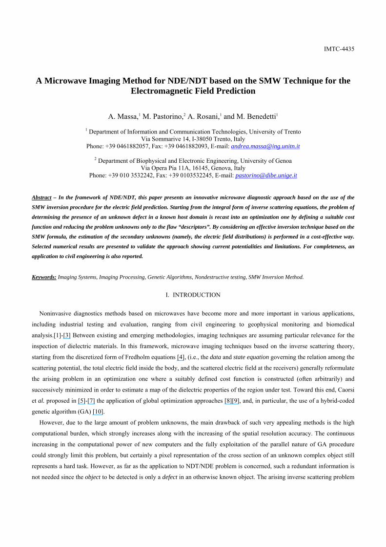
IMTC-4435
A Microwave Imaging Method for NDE/NDT based on the SMW Technique for the Electromagnetic Field Prediction
A. Massa,1 M. Pastorino,2 A. Rosani,1 and M. Benedetti1
1 Department of Information and Communication Technologies, University of Trento Via Sommarive 14, I-38050 Trento, Italy
Phone: +39 0461882057, Fax: +39 0461882093, E-mail: [email protected]
2 Department of Biophysical and Electronic Engineering, University of Genoa Via Opera Pia 11A, 16145, Genova, Italy
Phone: +39 010 3532242, Fax: +39 0103532245, E-mail: [email protected]
Abstract – In the framework of NDE/NDT, this paper presents an innovative microwave diagnostic approach based on the use of the
SMW inversion procedure for the electric field prediction. Starting from the integral form of inverse scattering equations, the problem of
determining the presence of an unknown defect in a known host domain is recast into an optimization one by defining a suitable cost
function and reducing the problem unknowns only to the flaw “descriptors”. By considering an effective inversion technique based on the
SMW formula, the estimation of the secondary unknowns (namely, the electric field distributions) is performed in a cost-effective way.
Selected numerical results are presented to validate the approach showing current potentialities and limitations. For completeness, an
application to civil engineering is also reported.
Keywords: Imaging Systems, Imaging Processing, Genetic Algorithms, Nondestructive testing, SMW Inversion Method.
I. INTRODUCTION
Noninvasive diagnostics methods based on microwaves have become more and more important in various applications,
including industrial testing and evaluation, ranging from civil engineering to geophysical monitoring and biomedical
analysis.[1]-[3] Between existing and emerging methodologies, imaging techniques are assuming particular relevance for the
inspection of dielectric materials. In this framework, microwave imaging techniques based on the inverse scattering theory,
starting from the discretized form of Fredholm equations [4], (i.e., the data and state equation governing the relation among the
scattering potential, the total electric field inside the body, and the scattered electric field at the receivers) generally reformulate
the arising problem in an optimization one where a suitably defined cost function is constructed (often arbitrarily) and
successively minimized in order to estimate a map of the dielectric properties of the region under test. Toward this end, Caorsi
et al. proposed in [5]-[7] the application of global optimization approaches [8][9], and, in particular, the use of a hybrid-coded
genetic algorithm (GA) [10].
However, due to the large amount of problem unknowns, the main drawback of such very appealing methods is the high
computational burden, which strongly increases along with the increasing of the spatial resolution accuracy. The continuous
increasing in the computational power of new computers and the fully exploitation of the parallel nature of GA procedure
could strongly limit this problem, but certainly a pixel representation of the cross section of an unknown complex object still
represents a hard task. However, as far as the application to NDT/NDE problem is concerned, such a redundant information is
not needed since the object to be detected is only a defect in an otherwise known object. The arising inverse scattering problem

IMTC-4435
is notably simplified as well as the dimension of the search space, thus allowing an effective use of a GA-based strategy. In this
framework, Caorsi et al. recently proposed a customized approach [11] and a successive extension [12][13], which
demonstrated their effectiveness in dealing with two-dimensional geometries. A further refinement of this method is presented
in this paper. The proposed improvement is aimed at considerably increase the convergence speed of the algorithm by
computing in a fast and more effective way the induced electromagnetic field. Moreover, such an approach avoids the coding
of the secondary unknowns in the arising chromosome.
The paper is organized as follows. After the problem description, the mathematical formulation (Sec. II) of the approach
will be described by focusing on the numerical procedure for the computation of the induced electric field distribution. Then, a
set of selected numerical results will be shown (Sec. III). A preliminary assessment will be performed by considering reference
scenarios. Then, the validation will be extended to more complex environments modeling realistic civil engineering test cases.
Finally, some conclusions will follow (Sec. IV).
II. MATHEMATICAL FORMULATION
Let us consider the geometry shown in Figure 1. An unknown defect (yellow area) lies in a known host medium (red area)
illuminated by a set of V TM unit plane waves, vincE , Vv ,...,1= . The test sample (formally the investigation domain) is
assumed to be of cylindrical shape, as in the case of a cement concrete or a column. It is surrounded by a circular arrangement
of probing antennas located at M positions ( )mm yx , , Mm ,...,1= and forming a microwave scanner. Starting from the
knowledge of the scattered field ),( mmscatt yxEν , Mm ,...,1= , Vv ,...,1= collected by the probing antennas, and of the incident
field ),( nninc yxEν Nn ,...,1= , Vv ,...,1= measured at N positions in the investigation domain, the reconstruction procedure is
aimed at finding the unknown descriptors of the crack assumed to be a homogeneous rectangle (i.e., the centre of mass ( )00 , yx ,
the orientation cα and the occupation rectangle defined by its dimensions cL and cW )
{ }00 ,,,, yxWLf ccccrack α= (1)
and the electric field distribution for the flaw configuration ( ){ }NnVvyxEf nnvtotfield ,...,1;,...,1;, === , by minimizing the
following cost function, Φ
( ) ( ) ( )fff StateData Φ+Φ=Φ (2)
where
( ){ }
∑∑
∑∑
= =
= =
ℑ−=Φ V M
mmmscatt
V M
m
mDatammscatt
Data
yxE
fyxEf
1 1
2
1 1
2
),(
),(
ν
ν
ν
ν
and
( ){ }
∑∑
∑∑
= =
= =
ℑ−=Φ V N
nnninc
V N
n
nStatenninc
State
yxE
fyxEf
1 1
2
1 1
2
),(
),(
ν
ν
ν
ν
.
IMTC-4435
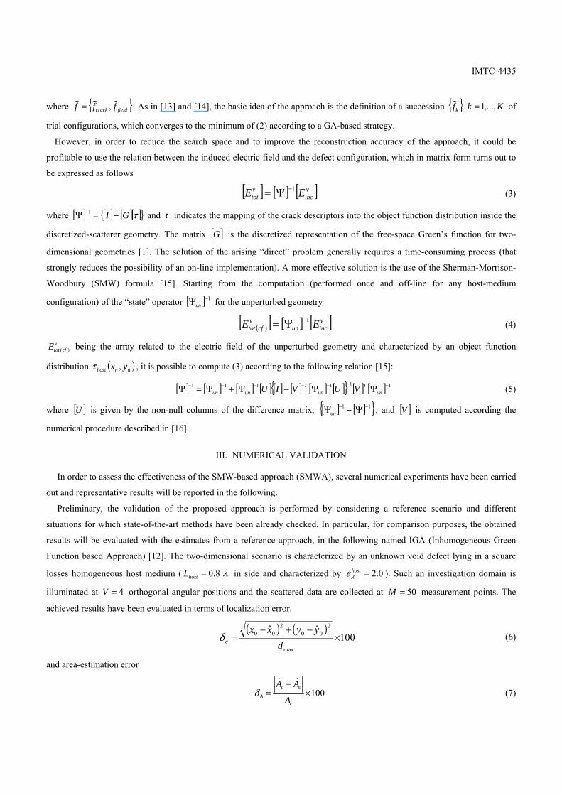
where { }fieldcrack fff ,= . As in [13] and [14], the basic idea of the approach is the definition of a succession { } Kkfk ,...,1, = of
trial configurations, which converges to the minimum of (2) according to a GA-based strategy.
However, in order to reduce the search space and to improve the reconstruction accuracy of the approach, it could be
profitable to use the relation between the induced electric field and the defect configuration, which in matrix form turns out to
be expressed as follows
[ ] [ ] [ ]vinc
vtot EE 1−Ψ= (3)
where [ ] [ ] [ ][ ]{ }τGI −=Ψ −1 and τ indicates the mapping of the crack descriptors into the object function distribution inside the
discretized-scatterer geometry. The matrix [ ]G is the discretized representation of the free-space Green’s function for two-
dimensional geometries [1]. The solution of the arising “direct” problem generally requires a time-consuming process (that
strongly reduces the possibility of an on-line implementation). A more effective solution is the use of the Sherman-Morrison-
Woodbury (SMW) formula [15]. Starting from the computation (performed once and off-line for any host-medium
configuration) of the “state” operator [ ] 1−Ψun for the unperturbed geometry
( )[ ] [ ] [ ]vincun
vcftot EE 1−Ψ= (4)
vcftotE )( being the array related to the electric field of the unperturbed geometry and characterized by an object function
distribution ( )nnhost yx ,τ , it is possible to compute (3) according to the following relation [15]:
[ ] [ ] [ ] [ ] [ ] [ ] [ ] [ ]{ } [ ] [ ] 111111 −−−−−−− ΨΨ−Ψ+Ψ=Ψ unT
unT
unun VUVIU (5)
where [ ]U is given by the non-null columns of the difference matrix, [ ] [ ]{ }11 −− Ψ−Ψun , and [ ]V is computed according the
numerical procedure described in [16].
III. NUMERICAL VALIDATION
In order to assess the effectiveness of the SMW-based approach (SMWA), several numerical experiments have been carried
out and representative results will be reported in the following.
Preliminary, the validation of the proposed approach is performed by considering a reference scenario and different
situations for which state-of-the-art methods have been already checked. In particular, for comparison purposes, the obtained
results will be evaluated with the estimates from a reference approach, in the following named IGA (Inhomogeneous Green
Function based Approach) [12]. The two-dimensional scenario is characterized by an unknown void defect lying in a square
losses homogeneous host medium ( λ8.0=hostL in side and characterized by 0.2=hostRε ). Such an investigation domain is
illuminated at 4=V orthogonal angular positions and the scattered data are collected at 50=M measurement points. The
achieved results have been evaluated in terms of localization error.
( ) ( )100
ˆˆ
max
200
200 ×
−+−=
dyyxx
cδ (6)
and area-estimation error
100ˆ
×−
=c
cc
A A
AAδ (7)
IMTC-4435
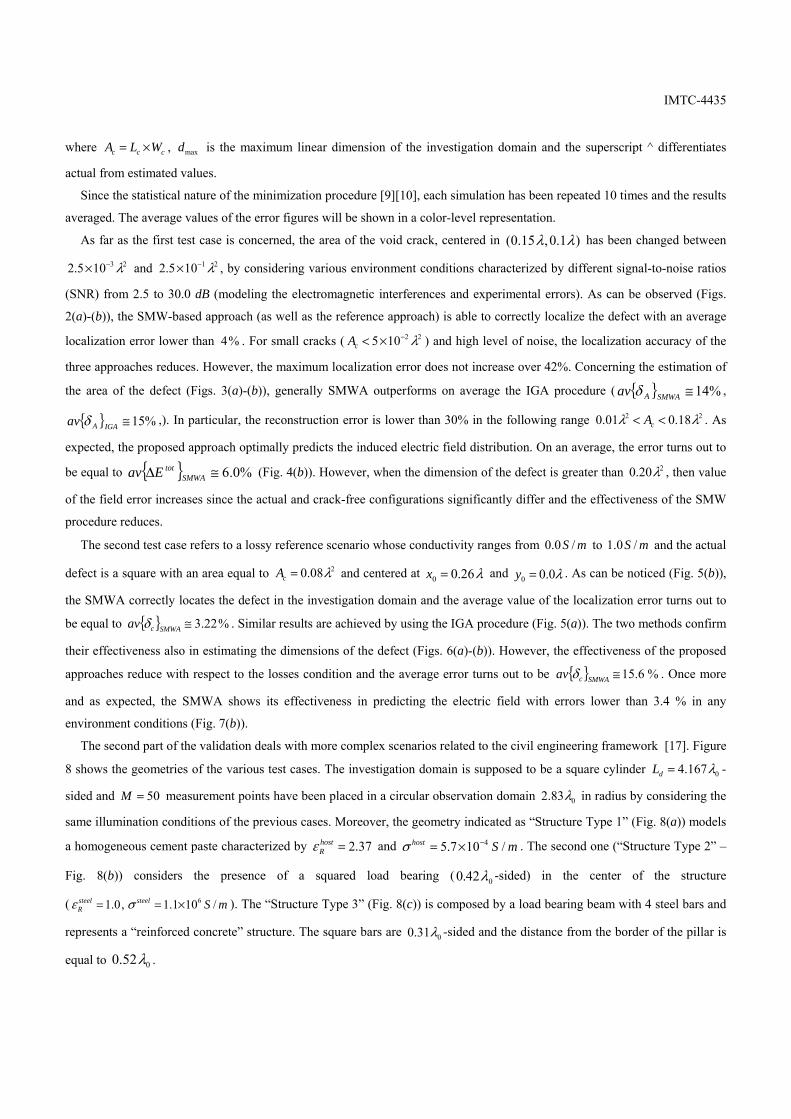
where ccc WLA ×= , maxd is the maximum linear dimension of the investigation domain and the superscript ^ differentiates
actual from estimated values.
Since the statistical nature of the minimization procedure [9][10], each simulation has been repeated 10 times and the results
averaged. The average values of the error figures will be shown in a color-level representation.
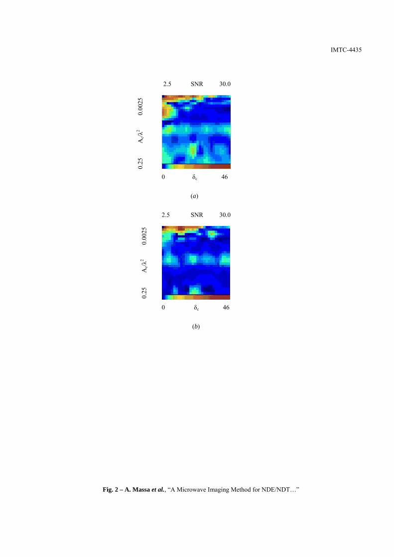
As far as the first test case is concerned, the area of the void crack, centered in )1.0,15.0( λλ has been changed between
23105.2 λ−× and 21105.2 λ−× , by considering various environment conditions characterized by different signal-to-noise ratios
(SNR) from 2.5 to 30.0 dB (modeling the electromagnetic interferences and experimental errors). As can be observed (Figs.
2(a)-(b)), the SMW-based approach (as well as the reference approach) is able to correctly localize the defect with an average
localization error lower than %4 . For small cracks ( 22105 λ−×<cA ) and high level of noise, the localization accuracy of the
three approaches reduces. However, the maximum localization error does not increase over 42%. Concerning the estimation of
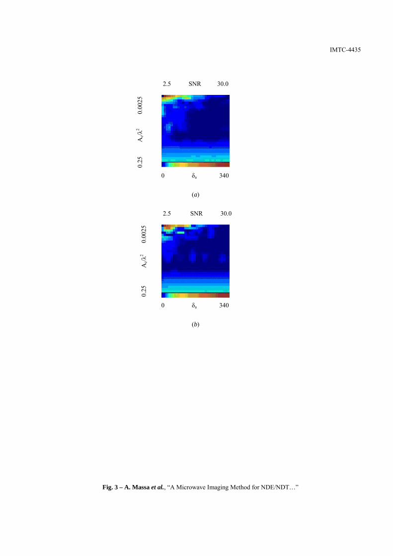
the area of the defect (Figs. 3(a)-(b)), generally SMWA outperforms on average the IGA procedure ( { } %14≅SMWAAav δ ,
{ } %15≅IGAAav δ ,). In particular, the reconstruction error is lower than 30% in the following range 22 18.001.0 λλ << cA . As
expected, the proposed approach optimally predicts the induced electric field distribution. On an average, the error turns out to
be equal to { } %0.6≅∆ SMWAtotEav (Fig. 4(b)). However, when the dimension of the defect is greater than 220.0 λ , then value
of the field error increases since the actual and crack-free configurations significantly differ and the effectiveness of the SMW
procedure reduces.
The second test case refers to a lossy reference scenario whose conductivity ranges from mS /0.0 to mS /0.1 and the actual
defect is a square with an area equal to 208.0 λ=cA and centered at λ26.00 =x and λ0.00 =y . As can be noticed (Fig. 5(b)),
the SMWA correctly locates the defect in the investigation domain and the average value of the localization error turns out to
be equal to { } %22.3≅SMWAcav δ . Similar results are achieved by using the IGA procedure (Fig. 5(a)). The two methods confirm
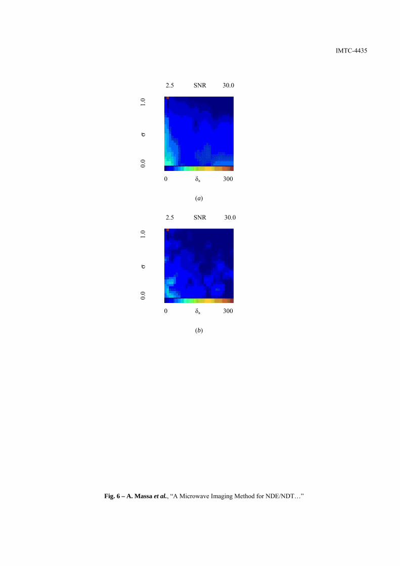
their effectiveness also in estimating the dimensions of the defect (Figs. 6(a)-(b)). However, the effectiveness of the proposed
approaches reduce with respect to the losses condition and the average error turns out to be { } %6.15≅SMWAcav δ . Once more
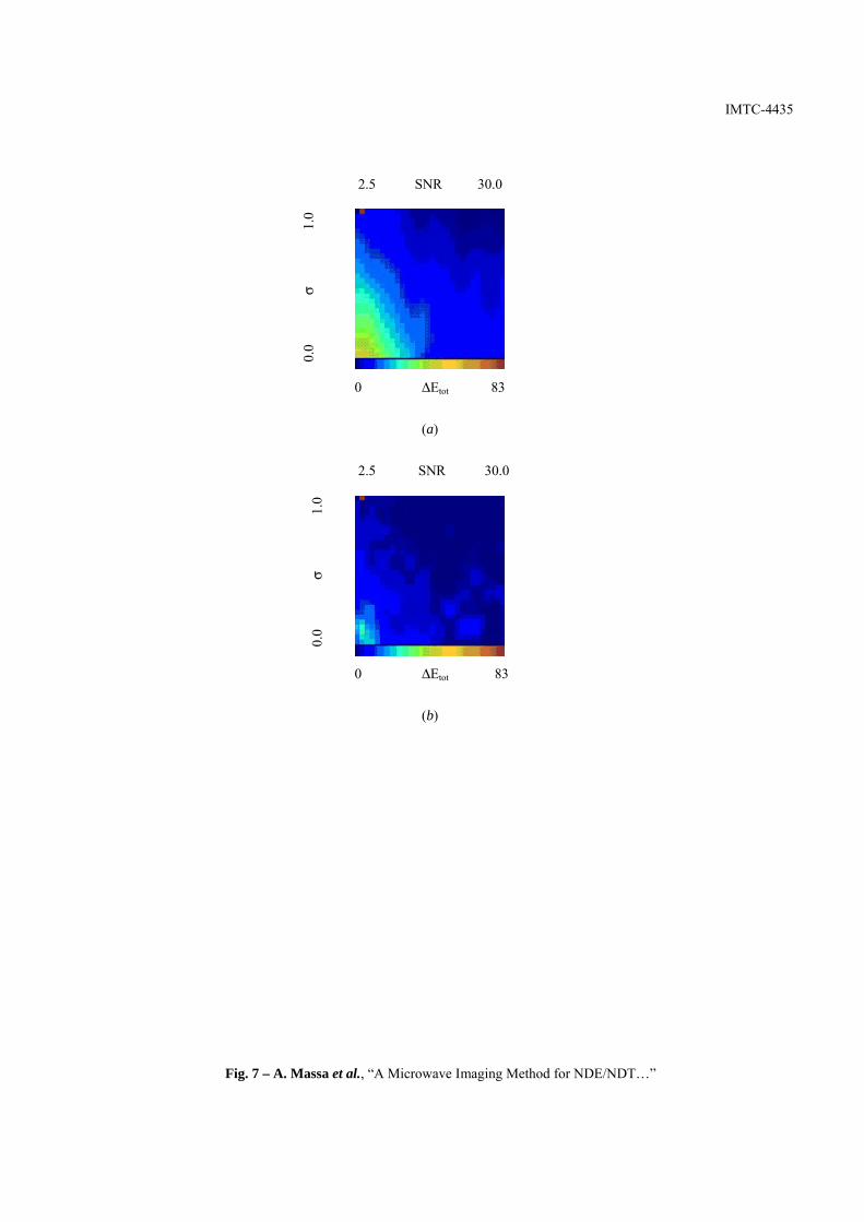
and as expected, the SMWA shows its effectiveness in predicting the electric field with errors lower than 3.4 % in any
environment conditions (Fig. 7(b)).
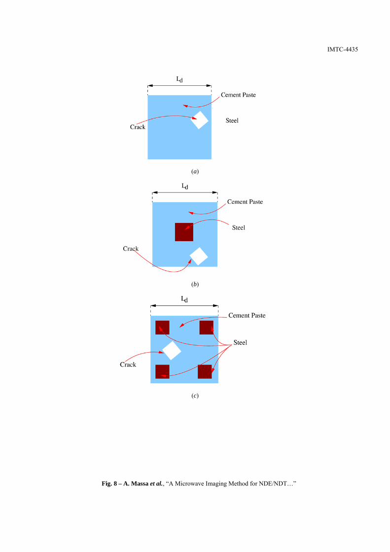
The second part of the validation deals with more complex scenarios related to the civil engineering framework [17]. Figure
8 shows the geometries of the various test cases. The investigation domain is supposed to be a square cylinder 0167.4 λ=dL -
sided and 50=M measurement points have been placed in a circular observation domain 083.2 λ in radius by considering the
same illumination conditions of the previous cases. Moreover, the geometry indicated as “Structure Type 1” (Fig. 8(a)) models
a homogeneous cement paste characterized by 37.2=hostRε and mShost /107.5 4−×=σ . The second one (“Structure Type 2” –
Fig. 8(b)) considers the presence of a squared load bearing ( 042.0 λ -sided) in the center of the structure
( mSsteelsteelR /101.1,0.1 6×== σε ). The “Structure Type 3” (Fig. 8(c)) is composed by a load bearing beam with 4 steel bars and
represents a “reinforced concrete” structure. The square bars are 031.0 λ -sided and the distance from the border of the pillar is
equal to 052.0 λ .
IMTC-4435
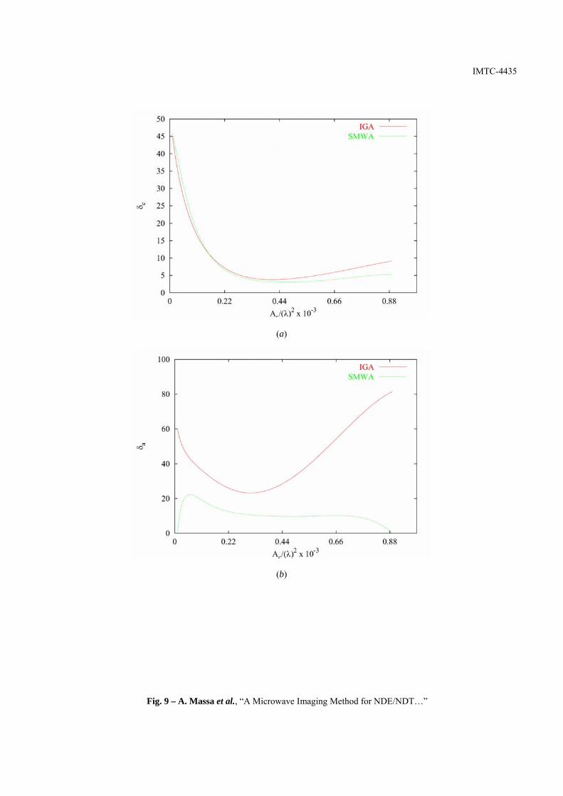
As far as the geometry shown in Fig. 8(a)), both the SMWA and the IGA techniques perform the localization of the defect
with a maximum error { } %10<cδ (Fig 9(a)) when the area of the crack satisfies the following relation
20
31022.0 λ−×>cA . However, the SMWA overcomes the results of the reference approach in estimating the area of the
crack. The error turns out to be { } %25<aδ in the all range of variation (Fig 9(b)).
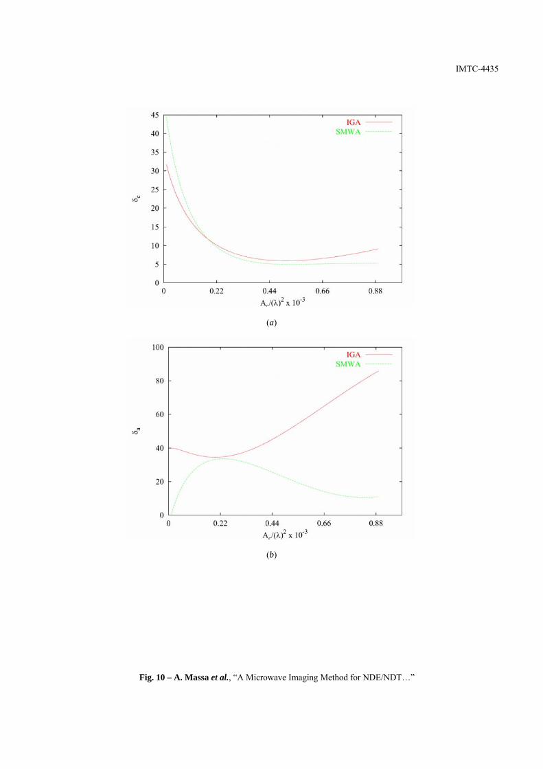
In dealing with an inhomogeneous medium (Fig. 8(b), “Structure Type 2”), the crack is again localized with an adequate
accuracy and the average error is equal to { } %2288.0,...,01.02
== cAc
av δλ
both in the case of SMWA and IGA (Fig. 10(a)). On the
other hand, the error in estimating the defect is considerably reduced using the new approach with error values { } %35<aδ
( { } %4788.0,...,01.02
== aAc
av δλ
for the IGA approach) (Fig. 10(b)).
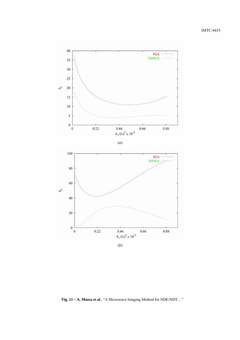
Finally, “Structure Type 3” (Fig. 8(c)) points out that the presence of a set of four steals bars significantly affects the
performances of the IGA method and seems to indicate better reconstruction capabilities of the SMWA method. As can be
observed (Fig. 11(a)-(b)), the results obtained with the SMWA approach overcome both in localization and crack dimensioning
that of the IGA approach. More in detail, { } %1088.0,...,01.02
== cAc
av δλ
and { } %38<aδ .
IV CONCLUSIONS AND FUTURE DEVELOPMENTS
In conclusion, a microwave imaging approach based on the solution of the inverse scattering equations has been proposed
by considering an effective use of the a-priori information of the scenario under test and a non-computationally expensive
numerical procedure for the field prediction. Selected numerical simulation with particular reference to realistic structures in
the framework of civil engineering have been considered and demonstrated a significant effectiveness of the proposed
approach in the defect retrieval.
Future developments and researches will be aimed at further exploit the a-priori information of the scenario under test in
order to allow an extension of the proposed procedure to three-dimensional geometries.
IMTC-4435
REFERENCES
[1] R. Zoughi, Microwave Testing and Evaluation. Kluwer Accademic Publishers, The Netherlands, 2000 [2] G.C. Giakos, M. Pastorino, F. Russo, S. Chowdhury, N. Shah, and W. Davros, “Noninvasive imaging for the new century”, IEEE Instrumentation and.
Measurement. Magazine, vol. 2, pp. 32-35, 1999. [3] E. C. Fear, P. M. Meaney, and M. A. Stuchly, “Microwaves for breast cancer detection,” IEEE Potentials, vol. 22, pp. 12-18, 2003. [4] D. S. Jones, The Theory of Electromagnetism. Oxford, U.K.: Pergamon Press, 1964. [5] M. Pastorino, A. Massa and S. Caorsi, “A microwave inverse scattering technique for image reconstruction based on a genetic algorithm,” IEEE
Transactions on Instrumentation and Measurement, vol. 49, pp. 573-578, June 2000. [6] A. Massa, “Genetic Algorithm (GA) Based Techniques for 2D Microwave Inverse Scattering,” in Recent Research Developments in Microwave Theory
and Techniques (Special Issue on Microwave Non-Destructive Evaluation and Imaging), Ed. M. Pastorino, Transworld Research Network Press, Trivandrum, India, pp. 193-218, 2002.
[7] M. Pastorino, A. Massa, and S. Caorsi, “Reconstruction algorithms for electromagnetic imaging,” Proc. IMTC 2002, Anchorage, Alaska, USA, pp. 1695-1799, May 21-23, 2002.
[8] D. E. Goldberg, Genetic Algorithms in Search, Optimization, and Machine Learning. Addison-Wesley, Reading, MA, USA, 1989. [9] J.M. Johnson and Y. Rahmat-Samii, “Genetic algorithms in engineering electromagnetics,” IEEE Transactions on Antennas and Propagation Magazine,
vol. 39, pp. 7-26, 1997. [10] S. Caorsi, A. Massa, and M. Pastorino, "A Computational Technique Based on a Real Coded Genetic Algorithm for Microwave Imaging Purposes",
IEEE Transactions on Geoscience and Remote Sensing Sensing - Special Issue on “Computational Wave Issues in Remote Sensing, Imaging and Target Identification,” vol. 38, pp. 1697-1708, 2000.
[11] M. Pastorino, A. Massa, and S. Caorsi, "A global optimization technique for microwave nondestructive evaluation," IEEE Transactions on Instrumentation and Measurement, vol. 51, pp. 666-673, 2002.
[12] S. Caorsi, A. Massa, M. Pastorino, A. Randazzo, and A. Rosani, “A reconstruction procedure for microwave nondestructive evaluation based on a numerically computed Green’s function,” Proc. IMTC 2003, Vail, Colorado, USA, pp. 669-674, May 20-22, 2003.
[13] S. Caorsi, A. Massa, M. Pastorino, and M. Donelli, “Improved microwave imaging procedure for non-destructive evaluations of two-dimensional structures,” IEEE Transactions on Antennas and Propagation, vol. 52, no. 6, pp. 1386-1397, June 2004.
[14] S. Caorsi, A. Massa, M. Pastorino, “A crack identification microwave procedure based on a genetic algorithm for nondestructive testing,” IEEE Transactions on Antennas and Propagation, vol. 49, pp. 1812-1820, 2001.
[15] E. Yip and B. Tomas, "Obtaining Scattering Solution for Perturbed Geometries and Materials from Moment Method Solutions”, ACES Journal, pp. 95-118, 1988.
[16] S. Caorsi, A. Massa, and M. Pastorino, “Application of the UMoM for the computation of the scattering by dielectrics with weakly nonlinear layers,” ACES Journal - Special Issue on “Advances in the Application of the Moment of Methods to Electromagnetic Radiation and Scattering Problems,” vol. 10, pp. 139-145, 1995.
[17] W. H. Hayt Jr., J. A. Buck, Engineering Electromagnetics, New York, USA, McGraw-Hill, 2001

IMTC-4435
FIGURE CAPTIONS
Figure 1. NDE/NDT problem geometry.
Figure 2. Test Case No 1. – Localization Error: (a) IGA and (b) SMWA. Figure 3. Test Case No 1. – Area Estimation Error: (a) IGA and (b) SMWA.
Figure 4. Test Case No 1. – Field Estimation Error: (a) IGA and (b) SMWA.
Figure 5. Test Case No 2. - Localization Error: (a) IGA and (b) SMWA.
Figure 6. Test Case No 2. – Area Estimation Error: (a) IGA and (b) SMWA.
Figure 7. Test Case No 2. – Field Estimation Error: (a) IGA and (b) SMWA.
Figure 8. Models of civil structures: (a) “Type 1”, (b) “Type 2”, and (c) “Type 3”.
Figure 9. Structure “Type 1” – Error Figures: (a) localization error and (b) area estimation error.
Figure 10. Structure “Type 2” – Error Figures: (a) localization error and (b) area estimation error.
Figure 11. Structure “Type 3” – Error Figures: (a) localization error and (b) area estimation error.

IMTC-4435
Fig. 1 – A. Massa et al., “A Microwave Imaging Method for NDE/NDT…”
IMTC-4435
2.5 SNR 30.0
0.25
A
c/λ2
0.00
25
0 δc 46
(a)
2.5 SNR 30.0
0.25
A
c/λ2
0.00
25
0 δc 46
(b)
Fig. 2 – A. Massa et al., “A Microwave Imaging Method for NDE/NDT…”
IMTC-4435
2.5 SNR 30.0
0.25
A
c/λ2
0.00
25
0 δa 340
(a)
2.5 SNR 30.0
0.25
A
c/λ2
0
.002
5
0 δa 340
(b)
Fig. 3 – A. Massa et al., “A Microwave Imaging Method for NDE/NDT…”

IMTC-4435
2.5 SNR 30.0
0.25
A
c/λ2
0.00
25
0 ∆Etot 61
(a)
2.5 SNR 30.0
0.25
A
c/λ2
0
.002
5
0 ∆Etot 61
(b)
Fig. 4 – A. Massa et al., “A Microwave Imaging Method for NDE/NDT…”

IMTC-4435
2.5 SNR 30.0
0.0
σ
1.0
0 δc 48
(a)
2.5 SNR 30.0
0.0
σ
1.0
0 δc 48
(b)
Fig. 5 – A. Massa et al., “A Microwave Imaging Method for NDE/NDT…”
IMTC-4435
2.5 SNR 30.0
0.0
σ
1.0
0 δa 300
(a)
2.5 SNR 30.0
0.0
σ
1.0
0 δa 300
(b)
Fig. 6 – A. Massa et al., “A Microwave Imaging Method for NDE/NDT…”
IMTC-4435
2.5 SNR 30.0
0.0
σ
1.0
0 ∆Etot 83
(a)
2.5 SNR 30.0
0.0
σ
1.0
0 ∆Etot 83
(b)
Fig. 7 – A. Massa et al., “A Microwave Imaging Method for NDE/NDT…”
IMTC-4435
(a)
(b)
(c)
Fig. 8 – A. Massa et al., “A Microwave Imaging Method for NDE/NDT…”
IMTC-4435
(a)
(b)
Fig. 9 – A. Massa et al., “A Microwave Imaging Method for NDE/NDT…”
IMTC-4435
(a)
(b)
Fig. 10 – A. Massa et al., “A Microwave Imaging Method for NDE/NDT…”
IMTC-4435
(a)
(b)
Fig. 11 – A. Massa et al., “A Microwave Imaging Method for NDE/NDT…”