A methodology for a Very Small Data Base design
33
A Methodology for Very Small Data Base Design C. Bolchini ∗ F. A. Schreiber L. Tanca Politecnico di Milano, Dipartimento di Elettronica e Informazione P.zza L. Da Vinci, 32 - 20133 Milano - Italy Abstract This paper proposes a design methodology for very small databases aimed at be- ing hosted by portable devices. Three main differences w.r.t. the traditional design methodologies are introduced: first, the main mobility issues are considered along with data distribution; second, context awareness is included in the data design issues to allow a full exploitation of context sensitive application functionalities; third, the peculiarities of the storage device(s) are taken into account by introduc- ing a logistic phase after the usual conceptual and logical phases. The three aspects together determine the VSDB ambient which is the set of personal and environ- mental characteristics determining the portion of data that must be stored on the portable device. This paper details the design methodology in its conceptual, logical and logistic phases. Key words: Very Small Data Base, DB Design Methodology, Portable Devices 1 Introduction The use of handheld devices, such as Smart Cards, Portable Data Assistants (PDA), Palm PCs and Cell Phones, to store data locally and to issue transac- tions against both local and remote data from Information Systems is being widely discussed in recent times [1,4,5,6,7]. Features required by portable de- vices in order to manage data are, for some aspects, similar to those found The work has been partially supported by the FIRB project MAIS ∗ Corresponding author. Tel. +39 0223993619, Fax +39 0223993410 Email addresses: bolchini@elet.polimi.it (C. Bolchini), schreibe@elet.polimi.it (F. A. Schreiber), tanca@elet.polimi.it (L. Tanca). Preprint submitted to Information Systems 29th October 2004 Figure1r
Transcript of A methodology for a Very Small Data Base design
A Methodology for Very Small Data Base
Design �
C. Bolchini ∗ F. A. Schreiber L. Tanca
Politecnico di Milano, Dipartimento di Elettronica e InformazioneP.zza L. Da Vinci, 32 - 20133 Milano - Italy
Abstract
This paper proposes a design methodology for very small databases aimed at be-ing hosted by portable devices. Three main differences w.r.t. the traditional designmethodologies are introduced: first, the main mobility issues are considered alongwith data distribution; second, context awareness is included in the data designissues to allow a full exploitation of context sensitive application functionalities;third, the peculiarities of the storage device(s) are taken into account by introduc-ing a logistic phase after the usual conceptual and logical phases. The three aspectstogether determine the VSDB ambient which is the set of personal and environ-mental characteristics determining the portion of data that must be stored on theportable device. This paper details the design methodology in its conceptual, logicaland logistic phases.
Key words: Very Small Data Base, DB Design Methodology, Portable Devices
1 Introduction
The use of handheld devices, such as Smart Cards, Portable Data Assistants(PDA), Palm PCs and Cell Phones, to store data locally and to issue transac-tions against both local and remote data from Information Systems is beingwidely discussed in recent times [1,4,5,6,7]. Features required by portable de-vices in order to manage data are, for some aspects, similar to those found
� The work has been partially supported by the FIRB project MAIS∗ Corresponding author. Tel. +39 0223993619, Fax +39 0223993410Email addresses: [email protected] (C. Bolchini),
[email protected] (F. A. Schreiber), [email protected] (L.Tanca).
Preprint submitted to Information Systems 29th October 2004
Figure1r
in Embedded Database systems [8], and range from very simple file systemfunctions to a full set of database management capabilities, including someACID transactions properties. Databases for very small devices - henceforthcalled Very Small Data Bases (VSDB) - are useful in various circumstances,among which some noticeable examples are listed below:
• The personal (micro)information system, the so-called citizen’s card, whichrecords administrative personal data like driver’s license and car informa-tion, passport, judicial register, etc.;
• The personal medical record, reporting the owner’s clinical history completewith all the past clinical tests and diagnoses; this is most useful with pa-tients suffering from some form of physical handicap or needing some criticaltreatment like periodical dialysis;
• The traveling salesman database, i.e. the “clients portfolio”, storing visitschedule and purchase orders along with the interesting information abouteach client’s particular needs;
• The personal travel database, recording all the travel (e.g. touristic) infor-mation considered interesting by the device owner.
The application domain deeply influences the model of the system, hence thedesign methodology. We can consider two opposite application examples out ofa continuum of architectural solutions: the first concerns a travelling salesmanPDA resident application; in this case the mobile VSDB stored on the PDA isa fragment of a larger Database, supporting a complex Information System,with a Global Schema, on which the VSDB Schema can be defined as a view.The second case deals with a touristic application running on a cell phone;in this case the personal travel database on the mobile device is a compositeinformation set obtained by integrating data from highly heterogeneous datasources for which no agreed schema exists [19].
The methodology we propose for Very Small Data Base design is based onthe classical three levels of the ANSI-SPARC model, sharing many issues withthe methodologies for distributed/federated database design [9,10]. However,three main differences w.r.t. the traditional design methodologies are intro-duced: first, since most interesting microdevices are portable, the main mo-bility issues are to be considered along with data distribution; second, contextawareness is included in the data design issues to allow a full exploitation ofcontext sensitive application functionalities; third, the peculiarities of the stor-age device(s) must be taken into account from the early steps, thus a logisticphase is added after the usual conceptual and logical phases, which supportsthe designer in the physical design task by taking into account the logisticaspects of data storage.
By examining these three aspects together we delineate the “VSDB ambient”,which is the set of personal and environmental characteristics determining the
2
portion of data that must be stored on the portable device [11].
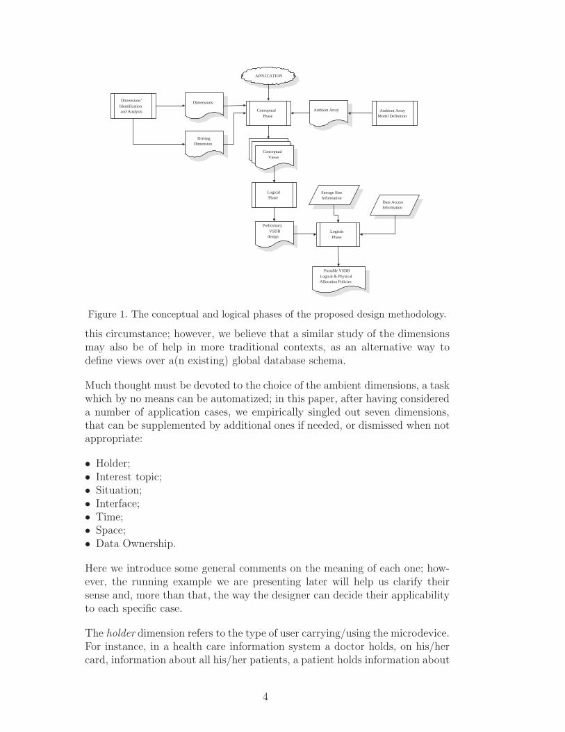
The first phase of the methodology we propose takes care of the conceptual,logical, and logistic aspects and has the main aim of ambient setting. Thesecond phase deals with physical, “on chip” features, concerning low-levelprivacy/security aspects [12] and physical memory data structures and algo-rithms [13], as depicted in Fig. 1. The aim of this paper is detailing the designmethodology in its early steps, i.e. the conceptual and logical/logistic phases.
In this paper we assume the existence of a (possibly distributed) database, forwhich a global schema has been defined and which is located on fixed devices.This means that VSDB’s are defined as (collections of) materialized views onthis database. Updates to the fixed as well as the Very Small databases areenvisaged, and their synchronization policies ar currently under study.
Future work is aimed at generalizing our research to the case where a mobiledevice joins in a complex information system where no global schema is known.A such application scenario has been delineated in [19].
Section 2 introduces the methodology for very small, portable databases, iden-tifying the main steps of the design process. Sections 3 and 4 detail each stepof the proposed approach, starting from the conceptual phase to proceed withthe logical one, using a running example to support the discussion. Section 5contains a brief discussion on the logistic phase of the VSDB methodology,already investigated in other referenced papers. Preliminary issues related totime and circumstances of synchronization are dealt with in Section 6.
2 Methodological Frame
At conceptual design time the “VSDB ambient” must be defined, which char-acterizes the VSDB with respect to the application, to the possible users thatwill carry the portable database, to the environment they are experiencing,and to their interests.
2.1 The ambient dimensions
The key elements of this phase are the “ambient dimensions”, which introducethe different perspectives the mobile device data are viewed from. These di-mensions support the definition of the portion of data residing on the mobiledevice at any given time, to be finally derived in terms of views over the globalschema. Studying the dimensions is essential and specific in the VSDB designmethodology, because the need of reducing database size is particularly felt in
3
LogisticPhase
Storage SizeInformation
Data AccessInformation
APPLICATION
ConceptualPhase
LogicalPhase
ConceptualView
ConceptualViewConceptual
Views
PreliminaryVSDB
design
Portable VSDBLogical & PhysicalAllocation Policies
Dimensions’Identificationand Analysis Ambient Array
Model Definition
Dimensions
DrivingDimension
Ambient Array
Figure 1. The conceptual and logical phases of the proposed design methodology.
this circumstance; however, we believe that a similar study of the dimensionsmay also be of help in more traditional contexts, as an alternative way todefine views over a(n existing) global database schema.
Much thought must be devoted to the choice of the ambient dimensions, a taskwhich by no means can be automatized; in this paper, after having considereda number of application cases, we empirically singled out seven dimensions,that can be supplemented by additional ones if needed, or dismissed when notappropriate:
• Holder;• Interest topic;• Situation;• Interface;• Time;• Space;• Data Ownership.
Here we introduce some general comments on the meaning of each one; how-ever, the running example we are presenting later will help us clarify theirsense and, more than that, the way the designer can decide their applicabilityto each specific case.
The holder dimension refers to the type of user carrying/using the microdevice.For instance, in a health care information system a doctor holds, on his/hercard, information about all his/her patients, a patient holds information about
4
him/herself, while a hospital administrator holds information about patients’and doctors’ accounting information in the hospital host computer. Note that,depending on the application, and if appropriate for analysis’ purposes, onemight identify as holders also people who use the information system, yet arenot microdevice holders; thus the latter character (i.e., the administrator) maybe considered as a holder if deemed interesting from the design viewpoint.
The interest topic dimension refers to the particular aspect/subject the usermight be interested in at a certain moment. In a tourist guide application thisdimension might refer to the choice of information about the city monuments,or about restaurants, etc. In many cases the designer might choose to ignorethis dimension, and interest topics might be selected on the fly, by performinga synchronization query to the fixed device(s) information during VSDB usage.
Using a somewhat hybrid approach, a priority level can be attached to eachinterest topic, in order to express the need of its availability (readiness). Anexample of the use of such a priority level is given by the need to manage flashmemory overflows that may occur at run time. In this case, a priority-basedmanagement algorithm may drive page swapping between the mobile deviceand the fixed information. On the other hand, we could “pin” some very highpriority information - e.g. “first aid” medical information such as blood group,allergy to specific drugs, etc. - in order to keep it stored on the smart card,avoiding the need of a network connection in case of emergency.
The situation dimension refers to the fact that during the device or the appli-cation life the user might wish to access different views of the data, being ableto perform different operations. Note that this dimension bears a more gen-eral significance than the mere consideration of different time periods; rather,it concerns different circumstances the system and the system users mightgo through during the Information System life. For instance, in the personalmedical information system, reporting the citizen’s clinical history, examplesof situations are the “normal”, i.e. healthy, owner’s state, as opposed to atemporary, “hospitalized” situation.
The interface dimension refers to the kind of access to the database content:indeed data access may be required by a human actor or by machine systems.This dimension suggests that different types of interacting entities may needdifferent data presentation profiles; i.e., for a human profile, internal IDs arenot necessary if not confusing, for a machine profile, internal IDs are necessarywhereas more expressive textual or visual descriptions are useless. Moreover,different humans (e.g. speaking different languages or physically disabled) ordifferent machines may require more specific interfaces.
The time dimension refers to the information lifespan the VSDB must store,e.g. current month, last week, etc..
5
The space dimension concerns a physical/geographic area related to the areathe device is currently located, e.g. current city, within a 300m radius, etc..
In mobile systems the two particular dimensions of time and space need specialconsideration: we call them kantian dimensions, from the “a priori” categoriesdefined by I. Kant in his “Critique of Pure Reason” [14]. A first peculiarity ofthe kantian dimensions is the fact that they can be implicitly evaluated by thedevice system clock (the time) and by a positioning system - GPS or other -(the spatial coordinates) and need not be explicitly provided by the user atquery or, in general, at transaction time. In this sense, we assume a relativisticview for space and time w.r.t. the “here” and “now” reference points, whichcan be easily translated, at query time, into a spatial or a temporal definitereference by binding them to the actual values of “here” and “now” [15]. Thesecond peculiarity lies in their orthogonality with respect to all of the otherdimensions: indeed, in traditional DBs attributes are mostly considered astime and space invariant, while this is not the case of Information Systemsbased on mobile devices, where many database attributes might be evaluatedat a given moment in time and at a given location.
On the other hand, we notice that when temporal or spatial attributes areexplicitly provided, i.e. when an absolute time or space reference is made inthe query, (e.g. in a query such as “...the aerobic classes in the Milan fitnessclub”), then they are better modelled as part of the interest topic dimension,because they are selecting absolute values of standard attributes (city, typeof exercise) of the considered entity and not relative to the current time andposition of query formulation.
The data ownership dimension determines which access rights apply to thestored data in terms of read and modify access permissions. It is possible toidentify three kinds of roles when accessing data in the VSDB [12]:
• the data owner;• the guest;• the device holder.
A data owner - in general a person, an authority or an institution - has fullpermissions to access its own data, in read and write mode; a guest is anyother user accessing part or all of the stored data with read only permissions.Altogether, an owner of some data can be a guest for other owners’ data; thereare also users only accessing data as guest, not owning any data on the device.The third role, and most interesting because distinctive of this context, is thedevice holder: although carrying the device, he/she is not necessarily the ownerof the information it bears, but he/she can be only a guest for data issued byothers. The main characteristic of the holder’s guest role is that he/she hasan unrestricted access to all data stored on his/her device, with at least read
6
permission, whereas other guests will only be entitled to read specific portionsof the data. Furthermore, if the device holds also the holder’s personal datathat he/she manages, then the holder will also be the owner of part of thedata, having a full access to them. This dimension will lead to the definitionof views allowing to grant access with different modes according to the useridentity and the data owner, yet it does not delimit the boundaries of theavailable information; thus it will be used to identify permission views, butnot for ambient identification.
Since the choice of the ambient dimensions is not trivial, some further elabo-ration is in order. Actually, analysis dimensions can be roughly classified intothe two categories of data-related dimensions and process-related dimensions:the former derive their values from the database schema, while the latter de-rive their values from the activities the system is supposed to perform. Amongthe dimensions listed above, holder, interest topic, time and space can be con-sidered as belonging to the first category, while situation, interface and ownerbelong to the second:
• The holder values indicate the characters who carry the device: for instance,in a medical database, at the schema level the patient’s device will containonly concepts pertaining to patients. Patients are most likely modelled as anentity in the medical database. At the instance level, further cutting per-formed by a selection on the patient’s identifier (e.g. SSN) will also eliminatethe data pertaining to all patients except the specific device holder.
• The interest topic is also data-related, since it applies to the set of possiblevalues of an entity attribute, characterizing the entity records with respectto possible categories of values. An example is “chinese restaurants” in thetravel database.
• The time dimension can only be applied if some time-related attribute ispresent in the database. Of course, views based on this dimension need somepreprocessing, since first the “now” must be translated into the current time,and then a selection based on its value can be applied.
• The space dimension behaves similarly, and needs preprocessing too, for theinterpretation of the “here”.
On the other hand:
• The situation values are typically related to the various phases or activitiesthe whole system or the specific VSDB is supposed to undergo; for instance,in a medical database, the doctor’s palm computer might carry, in differentmoments, information used and updated during house calls or those relatedto office visits, while the patient’s smart card might contain informationread and updated during a hospital sojourn as opposed to that related tonormal life.
• The interface dimension filters, in fact, only the information format used
7
and updated by a machine rather than by a human.• Also the owner dimension values are not directly present in the database:
rather, they dictate authorizations for actors who read/modify the database,and who need not be part of the database itself. As such, views for the ownerdimension’s values must be derived from the study of the actions the varioussystem owners will carry out on the data.
Accordingly, values of the data-related dimensions will constitute attributesand domain values for the selections, projections and joins that tailor thedatabase schema and the database itself, while values of the process-relateddimensions will drive database tailoring by answering the questions: “whichdata will be used by this activity?”, or: “which data will be produced by thisactivity?”.
This classification helps the designer finding the dimensions for the systemhe/she has to analyze and, at the same time, constrains him/her to reshapethe global design in order for it to be coherent with the dimension values’choice. Several feedback cycles between conceptual design and dimensions’choice might be needed before the designer is completely satisfied.
The dimension analysis and the consequent view definitions, carried out partlyat conceptual, partly at logical design time, contribute to the limitation of theDB size in view of the need to take memory size restrictions into account.However, at this level no real evaluation is made yet as for the actual numberof bytes to be stored; the choice of the cardinality of on-device relations isdelayed to a further step (the so-called logistic phase), in order to meet theknown storage constraints.
2.2 VSDB Design Methodology
The starting point of our design methodology is a model of the application:either a complete conceptual schema of the entire database supporting it, ora set of more or less integrated conceptual schemata describing the severalaspects of the reality of interest; in this paper we only deal with the formerhypothesis. As mentioned before, three are the main phases:
• conceptual phase, producing and acting upon an E-R representation of theapplication,
• logical phase, producing and acting upon the logical schemata defining thedatabase elements, and
• logistic phase, working at a lower level to determine table size, and the mostconvenient data structures and allocation policies for table implementation.
8
Each phase is further decomposed into steps, leading the designer to the def-inition of the databases to be held by the portable device.
In order to illustrate the various methodology steps, we will make use of arunning example, based on a fitness franchising with a number of clubs allover the world. Here, club members and operators are the information systemusers; each one carries a Smart Card with his/her personal data, which canbe read and modified when inserted either in one of the fitness machines or ina desktop computer.
3 Conceptual phase
The conceptual phase aims at identifying the portion of the global databaseto be stored on the portable devices. The decision to store only a part of thecomplete database is determined here by limited device resources as well asby mobility/interest aspects. As a result, its application field can be naturallyextended also to cope with devices endowed with larger memories, where mo-bility is a relevant issue and the device holder is not interested in carryingaround the complete information set; moreover the future extensions towardsa peer-to-peer heterogeneous framework (as the case of a travel informationapplication) further strengthen the need for such a methodology. Therefore, asthe improvements contributed by new technology will allow the realization ofportable devices endowed with larger memories, our methodology for the con-ceptual phase will be adopted to tailor the database according to the currentcontext.
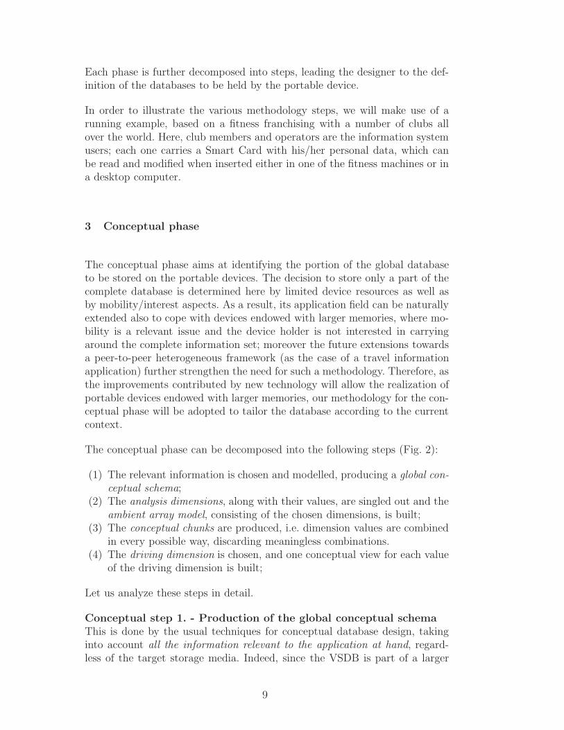
The conceptual phase can be decomposed into the following steps (Fig. 2):
(1) The relevant information is chosen and modelled, producing a global con-ceptual schema;
(2) The analysis dimensions, along with their values, are singled out and theambient array model, consisting of the chosen dimensions, is built;
(3) The conceptual chunks are produced, i.e. dimension values are combinedin every possible way, discarding meaningless combinations.
(4) The driving dimension is chosen, and one conceptual view for each valueof the driving dimension is built;
Let us analyze these steps in detail.
Conceptual step 1. - Production of the global conceptual schemaThis is done by the usual techniques for conceptual database design, takinginto account all the information relevant to the application at hand, regard-less of the target storage media. Indeed, since the VSDB is part of a larger
9
GlobalConceptual
Schema
ConceptualChunks
ConceptualView
[dim i = value1 ]
ConceptualView
[dim i = value1 ]
ConceptualView
[Drdim = value1 ]
Conceptual ViewCreation
Conceptual ChunkCreation
APPLICATION
Dimensions’Identificationand Analysis
Dimensions
DrivingDimension
Drdim
Ambient ArrayModel Definition
Ambient Array
Figure 2. The steps of the conceptual phase.
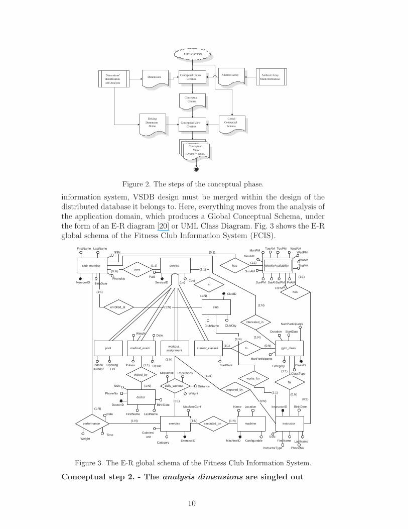
information system, VSDB design must be merged within the design of thedistributed database it belongs to. Here, everything moves from the analysis ofthe application domain, which produces a Global Conceptual Schema, underthe form of an E-R diagram [20] or UML Class Diagram. Fig. 3 shows the E-Rglobal schema of the Fitness Club Information System (FCIS).
InstructorType
(0:1)
FriPM
FriAM
ThuPM
ThuAM
club_member
exercise
daily_workout
(0:1)
workout_assignment
doctor
visited_by
(1:N)
medical_exam
(1:1)
current_classes
serviceuses
(0:N)
(1:1)
gym_class
by
instructor
to(1:1) (0:N)
(0,N)
(1:1)
prepared_by
(1:1)
(t,e)
machineexecuted_on(1:N) (1:N)
(1:N)
performance(1:N)
pool
Indoor/Outdoor
OpeningHrs
MemberID ServiceID
MachineID
InstructorIDDoctorID
ClassID
FirstName LastName
FirstName
FirstName LastName
PhoneNo
SSN
SSN
SSN
BirthDateBirthDate
PhoneNo
LastName
PhoneNo
BirthDate
Paid
ClubName
StartDate
StartDateDuration
MaxParticipants
NumParticipants
Category
Category
Cost
DateWeight
Pulses Result
ExerciseID
Calories/unit
MachineConf
Repetitions
Weight
Sequence
(1:N)
Name
Date
TimeWeight
Configurable
(0:N)
Location
has(1:1)
MonAM
MonPMTueAM TuePM
has
SunAM
SunPM
WedAMWedPM
SatAMSatPM
WeeklyAvailability
interested_in
(1:N)
ClassType
(0:1)
(1:1)
Distance
club
at
ClubCity
(1:1)
ClubID
enrolled_at (1:N)
(1:1)
works_for
(1:1)
(1:N)
(1:N)
(1:N)
Figure 3. The E-R global schema of the Fitness Club Information System.
Conceptual step 2. - The analysis dimensions are singled out
10
Analysis dimensions provide the different perspectives the mobile device isviewed from, and are used to set out the VSDB ambient. The dimensions listedin Subsection 2.1 are considered and their suitability to the application prob-lem is evaluated. For instance, in the fitness center case, the holder dimension(referring to the type of user carrying the microdevice) generates the followingSmart Card holders: {club member, class instructor, personal trainer}(pers trainer in the sequel), whose views over the whole information systemwill be quite different. As already noticed, one might identify as holders alsopeople who use the information system, but not as microdevice holders. Ifsuch a choice be made, an additional holder might be the club secretary, orclub administrator, using the information system from his/her workstation.
Note that the dimensions and the dimension values are to be coherent withthe global database schema, and the designer should be aware that a pos-sible feedback might be produced towards Conceptual Step 1. As far as thedata-related dimensions are concerned, in order for the dimension values to belater instantiated, such values must be present as a component of the schemaitself. For instance, in case the relational model be used for the logical de-sign, the dimension values may become either table names or attributes of thedatabase tables. Similarly, for the process-related dimensions we have to checkthe correspondence between the dimension values and the data that are usedor produced by the activity the dimension refers to.
Consider for example the holder dimension (a data-related one) and observethat, in the global conceptual schema, there are a CLUB MEMBER entity andan INSTRUCTOR entity, the latter with as attribute a flag InstructorType
with values pers trainer and class instructor. Note that these two en-tities have almost the same set of attributes, thus a schema revision is inorder, concentrating all the common attributes in a PERSON entity (actuallya generalization of the two); the same holds for the DOCTOR entity, which isalso included in PERSON. Thus the PERSON entity features a new attributeperson type with values club member, pers trainer, class instructor anddoctor (we omit the diagram for brevity reasons).
Moreover, the weak entity WEEKLY AVAILABILITY, which in the originalE-R schema is identified by the CLUB MEMBER or the INSTRUCTOR en-tities, will be correctly linked to the unique PERSON entity. Please note thatwe will not include doctors among the portable database holders, since in thepresent application there is no need for such a role to carry around informationon the members’ medical visits.
For the interest topic dimension of the FCIS example we have selected thevalues listed below; this dimension is also a data-related one: observe that itsvalues are either attributes or entity specializations in the global conceptualschema:
11
• Gym class type,• Exercise cat,• Service type.
Consider now the situation dimension: it is a process-related one. In our run-ning example, at the beginning of each semester there is a moment whereclasses are planned and members can enroll. At this time the members’ avail-ability information (in terms of suitable hours) is collected, in order to scheduleclasses. During the semester, once the classes have been formed, this informa-tion has no relevance. Thus, two situations are envisioned:
• Semester enrollment (enrol phase): initial stage when members subscribeto the classes they would like to attend, providing their weekly availabil-ity so that classes can be scheduled according to members’ and trainers’preferences.
• Semester activity (class time): when all timetables for classes are definedand members use the available services. If a member starts attending thegym at this stage, he/she skips the previous phase and can be directlyenrolled in one of the existing classes. Note that, for example, data onweekly availability are used by the previous situation, and are of no use tothis one.
The interface dimension refers to the mode used to access the database con-tent. This is also a process-related dimension. In the case of our gym appli-cation, we have a scenario where the club member inserts his/her personalSmart Card for the machine to read; the machine itself reads the trainee dataand sets up the established exercise program for that member. That meansthat the personal Smart Card, when inserted into a fitness machine of theclub, only provides machine related data, i.e. there is no need for the clubmember to hold, in his/her card, a textual description of the exercises he/sheis performing on each given machine. Values for this dimension are human andmachine.
The time dimension refers to the information lifespan the VSDB must store:for example, one could save the whole history of the member’s performance inthe fixed host machine of the sports hall where the member has registered inthe first place, keeping only the last month’s performances on the card itself.Of course this need presupposes the existence of dates in the database schema.
The space dimension concerns the (current) physical area. For example, theFCIS member whose home sport hall is located in Milan is interested, duringa work trip in New York, to all the sport halls of the same club in that city,disregarding the information about the other associated sport halls located inthe rest of the world, even in his/her own home club.
Note that time and space granularities must fit the application needs. For
12
example, a tourist application will use infrared sensors with a meter resolu-tion when browsing through exhibition rooms in a museum while it will useGPS with some tens of meters resolution when wandering among the city’smuseums. Therefore the measure units for these dimensions must be takeninto account in the design process, and the choice of the granularity of thedimensions of time and space should be explicitly provided for each attributereferring to these dimensions.
The data ownership dimension concerns access rights: read, update, deleteand insert rights to the VSDB information might be different depending onthe user categories. Recall that access rights are analyzed w.r.t. user cate-gories different from the categories of device holders: in the FCIS example itmight be the case that a member’s personal trainer has modify right on themember’s training program; the member, in turn, may read his/her assignedexercises, but cannot modify them. It may well happen that other users of theinformation system, normally accessing fixed devices, have rights which areorthogonal to the holders’ access rights: for example the local club adminis-tration might be the unique owner of modify rights on the members’ paymentinformation. Moreover, the doctor performing the periodical physical controlson the club members does not have a personal Smart Card, even though med-ical data are stored in the fixed database of the center and some of them areprotected against modify actions by other parties.
Generally speaking, access rights can be expressed by a four rows (modes) ta-ble, whose columns represent the Actor types and whose rows represent accessmodes, each entry being the View for Actor(j) with access right Mode(i).
V(i,j) = (Mode, Actor type)
where:
Mode = {insert, read, update, delete}
For example, in the fitness club application,
Actor type = {club member, class instructor, pers trainer,
club administrator, doctor}
A general constraint is that
⋃
i=insertj=1,n
Vi,j = G
13
⋃
i=readj=1,n
Vi,j = G
where G is the global schema; i. e. all the elements of the global schema mustbe inserted and must be read by some actor. Accordingly, we analyze theowner dimension as a process-related one.
Note that the owner dimension has been analyzed and will generate appro-priate views and authorizations, but we do not expect to use it for tailoring(subsetting) the data that has to be stored locally on the device; coherently,it does not appear in the ambient array model:
<holder, interest topic, situation, interface, time, space> .
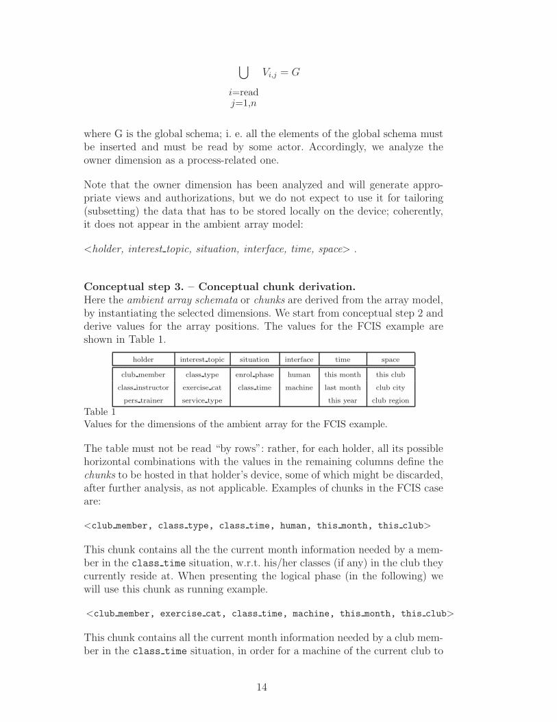
Conceptual step 3. – Conceptual chunk derivation.Here the ambient array schemata or chunks are derived from the array model,by instantiating the selected dimensions. We start from conceptual step 2 andderive values for the array positions. The values for the FCIS example areshown in Table 1.
holder interest topic situation interface time space
club member class type enrol phase human this month this club
class instructor exercise cat class time machine last month club city
pers trainer service type this year club region
Table 1Values for the dimensions of the ambient array for the FCIS example.
The table must not be read “by rows”: rather, for each holder, all its possiblehorizontal combinations with the values in the remaining columns define thechunks to be hosted in that holder’s device, some of which might be discarded,after further analysis, as not applicable. Examples of chunks in the FCIS caseare:
<club member, class type, class time, human, this month, this club>
This chunk contains all the the current month information needed by a mem-ber in the class time situation, w.r.t. his/her classes (if any) in the club theycurrently reside at. When presenting the logical phase (in the following) wewill use this chunk as running example.
<club member, exercise cat, class time, machine, this month, this club>
This chunk contains all the current month information needed by a club mem-ber in the class time situation, in order for a machine of the current club to
14
assign the appropriate exercise suite, w.r.t. the exercise categories containedin his/her fitness program.
<class instructor, class type, enrol phase, human, this month, this club>
This chunk contains the current month information class instructors need inat enrollment time (about the club they currently reside at) e.g., the numberand category of the members that have so far asked to be enrolled in theircourse(s).
Chunk derivation must be done with an eye to the chunk’s actual significance;indeed, only some of the possible combinations of dimension values make sense.Consider for example the chunks
<club member, class type, enrol phase, machine, this month, this club>
<pers trainer, class type, enrol phase, human, this month, this club>
Quite naturally, the designer may choose to discard them, since neither ma-chines nor personal trainers views use or produce data in the class schedulesituation.
As a matter of fact, the task of chunk discarding can be at least partiallyautomated. At the moment we are investigating techniques to perform thistask at least in a semi-automatic way, by exploiting (inclusion) dependencieseither between dimension values or between dimension values and databaseschema elements. In a wider view of the problem, we study the ambient di-mensions and their values as an ontology with several hierarchical levels, anddefine dependencies which cut out whole tree branches.
As a conclusion of this phase we assemble chunks to define which informa-tion is to be stored on a single device. For example, during class time a clubmember’s Smart Card will contain all the chunks related to the member’spersonal training program and to the courses he/she has enrolled in. Or, dur-ing the enrollment phase, a class instructor’s Smart Card will contain all thechunks related to all the possible courses of his/her competence that might belaunched, with the enrollment status of all the interested club members; in theclass phase, when all the classes have already been formed, the hypotheticalclasses are removed and the actual classes assigned to that class instructor areinserted, along with their composition, time and location.
Conceptual step 4. - Choice of the driving dimension.
Depending on the application, the designer should decide which dimension iscentral to the whole analysis process. The driving dimension’s views will bebuilt at conceptual design time, while all the other dimensions’ views will be
15
derived at logical design time.
The choice of the driving dimension is supported by the observation of theglobal conceptual schema, where the driving dimension’s data must constitutethe virtual center of the device data schema. In most applications, this role isnaturally taken by the holder dimension.
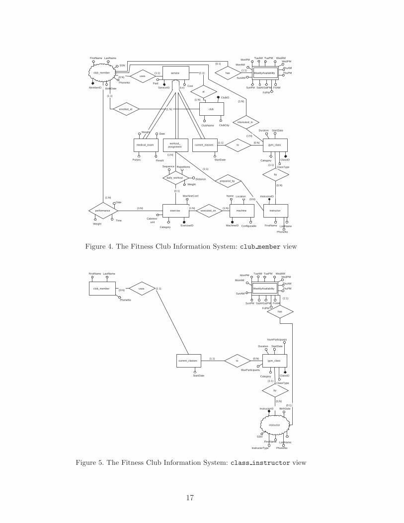
Consider the FCIS example: to begin with, at the schema level, starting fromeach of the entities referring to device holders (club member, class instructor,and pers trainer), one can tailor the conceptual views as snowflakes whosecenters are just the entities derived from the dimension’s values (Fig. 4, 5 and6 show the ER view schemata) 1 .
Further tailoring takes place at the instance level, where the snowflake centersare reduced to one singleton entry, i.e. the unique record referring to thespecific holder’s data.
We point out that, to our experience, the holder dimension has always quali-fied as the most appropriate for the role of driving dimension; this is coherentwith a “holder-centric” view of the design, but other dimensions might bechosen as well. For instance, another appropriate driving dimension is interesttopic, which could center database subsetting on the VSDB users’ interests. Ina tourist guide application, we could tailor one VSDB on information aboutcity monuments, another on hotels and restaurants, and another one on infor-mation about entertainments.
However, when this design choice is made, three main requirements for a di-mension to qualify as driving must be satisfied, i.e.: (1) the driving dimensionvalues must be present as entities in the conceptual schema; (2) the con-ceptual views referring to each particular driving dimension value must havea snowflake configuration, centered on that value’s entity; (3) each of thesesnowflake-center entities must have an attribute which, when selected on aspecific value, makes the entity collapse into a singleton record.
As a result, a reconciliation work might be needed, since the conceptualschemata produced by analyzing the application from the viewpoints of thevarious dimension values must be reconciled with the Global Conceptual Schema,in order for the former to be perceived as views over the latter, and for thelatter to satisfy the three requirements above.
1 In the view schemata we represent the entities related to the respective holdersby a small cloud.
16
(0:1)
FriPM
FriAM
ThuPM
ThuAM
exercise
daily_workout
(0:1)
workout_assignment
medical_exam current_classes
serviceuses(0:N)
(1:1)
gym_class
by
instructor
to(1:1) (0:N)
(0,N)
(1:1)
prepared_by
(1:1)
(t,e)
machineexecuted_on(1:N) (1:N)
(1:N)
performance(1:N)
MemberID ServiceID
MachineID
ClassID
FirstName LastName
FirstName
PhoneNo
SSN
PhoneNo
LastName
BirthDate
Paid
ClubName
StartDate
StartDateDuration
Category
Category
Cost
DateWeight
Pulses Result
ExerciseID
Calories/unit
MachineConf
Repetitions
Weight
Sequence
(1:N)
Name
Date
TimeWeight
Configurable
(0:N)Location
has(1:1)
MonAM
MonPMTueAM TuePM
SunAM
SunPM
WedAMWedPM
SatAMSatPM
WeeklyAvailability
interested_in
(1:N)
ClassType
Distance
club
at
ClubCity
(1:1)
ClubID
enrolled_at (1:N)
(1:1)
club_member
InstructorID
(1:N)(1:N)
Figure 4. The Fitness Club Information System: club member view
instructor
InstructorType
FriPM
FriAM
ThuPM
ThuAM
club_member
current_classes
uses(0:N)
(1:1)
gym_class
by
to(1:1) (0:N)
(0,N)
(1:1)
InstructorID
ClassID
FirstName LastName
FirstName
PhoneNo
SSN
BirthDate
PhoneNo
LastName
StartDate
StartDateDuration
MaxParticipants
NumParticipants
Category
MonAM
MonPMTueAM TuePM
has
SunAM
SunPM
WedAMWedPM
SatAMSatPM
WeeklyAvailability
ClassType
(0:1)
(1:1)
Figure 5. The Fitness Club Information System: class instructor view
17
InstructorType
FriPM
FriAM
ThuPM
ThuAM
club_member
exercise
daily_workout
(0:1)
workout_assignment
uses(0:N) (1:1)
prepared_by
(1:1)
machineexecuted_on(1:N) (1:N)
MachineID
InstructorID
FirstName LastName
FirstName
PhoneNo
SSN
BirthDate
PhoneNo
LastNameCategoryExerciseID
Calories/unit
MachineConf
Repetitions
Weight
Sequence
(1:N)
NameConfigurable
(0:N)
Location
MonAM
MonPMTueAM TuePM
has
SunAM
SunPM
WedAMWedPM
SatAMSatPM
WeeklyAvailability
(0:1)
(1:1)
Distance
pers_trainer
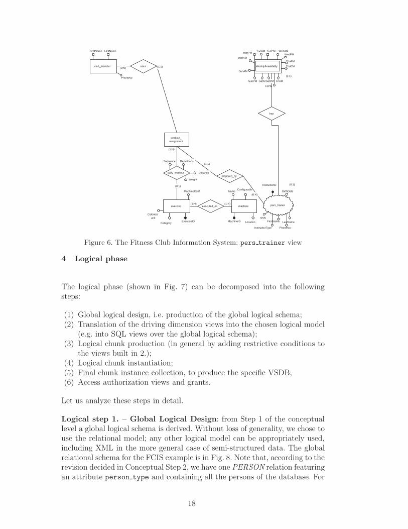
Figure 6. The Fitness Club Information System: pers trainer view
4 Logical phase
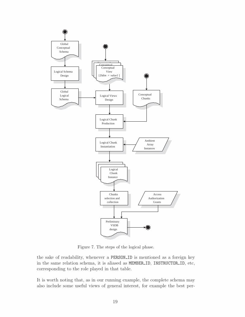
The logical phase (shown in Fig. 7) can be decomposed into the followingsteps:
(1) Global logical design, i.e. production of the global logical schema;(2) Translation of the driving dimension views into the chosen logical model
(e.g. into SQL views over the global logical schema);(3) Logical chunk production (in general by adding restrictive conditions to
the views built in 2.);(4) Logical chunk instantiation;(5) Final chunk instance collection, to produce the specific VSDB;(6) Access authorization views and grants.
Let us analyze these steps in detail.
Logical step 1. – Global Logical Design: from Step 1 of the conceptuallevel a global logical schema is derived. Without loss of generality, we chose touse the relational model; any other logical model can be appropriately used,including XML in the more general case of semi-structured data. The globalrelational schema for the FCIS example is in Fig. 8. Note that, according to therevision decided in Conceptual Step 2, we have one PERSON relation featuringan attribute person type and containing all the persons of the database. For
18
GlobalConceptual
Schema
GlobalLogicalSchema
Logical ViewsDesign
Logical SchemaDesign
Logical ChunkProduction
ConceptualChunks
AmbientArray
Instances
Logical ChunkInstantiation
LogicalChunkLogical
ChunkLogicalChunk
Instance
AccessAuthorization
Grants
Chunksselection and
collection
PreliminaryVSDB
design
ConceptualView
[dim i = value1 ]
ConceptualView
[dim i = value1 ]
ConceptualView
[Ddim = value1 ]
Figure 7. The steps of the logical phase.
the sake of readability, whenever a PERSON ID is mentioned as a foreign keyin the same relation schema, it is aliased as MEMBER ID, INSTRUCTOR ID, etc,corresponding to the role played in that table.
It is worth noting that, as in our running example, the complete schema mayalso include some useful views of general interest, for example the best per-
19
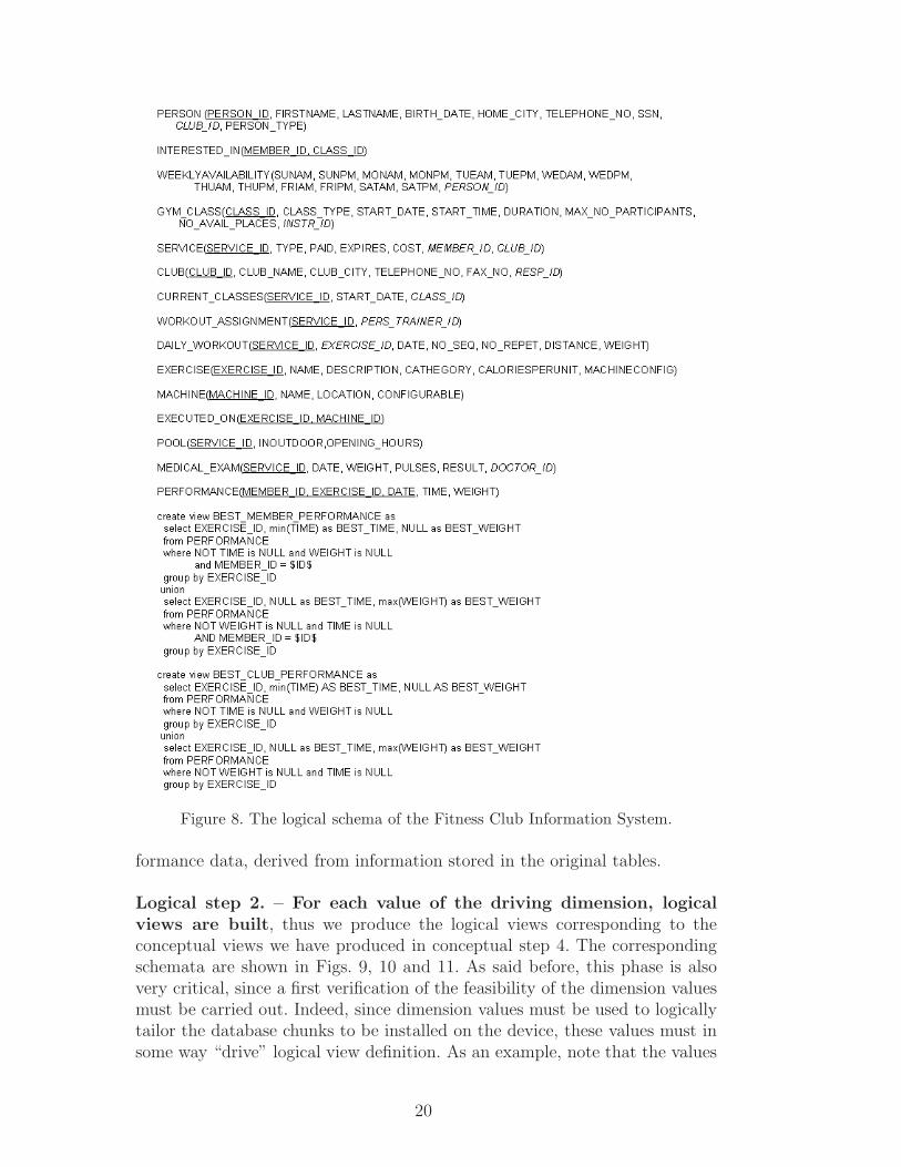
Figure 8. The logical schema of the Fitness Club Information System.
formance data, derived from information stored in the original tables.
Logical step 2. – For each value of the driving dimension, logicalviews are built, thus we produce the logical views corresponding to theconceptual views we have produced in conceptual step 4. The correspondingschemata are shown in Figs. 9, 10 and 11. As said before, this phase is alsovery critical, since a first verification of the feasibility of the dimension valuesmust be carried out. Indeed, since dimension values must be used to logicallytailor the database chunks to be installed on the device, these values must insome way “drive” logical view definition. As an example, note that the values
20
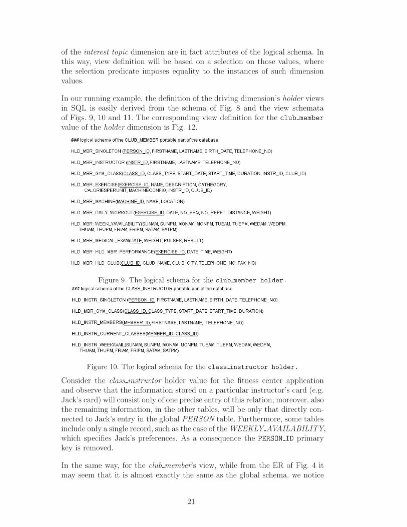
of the interest topic dimension are in fact attributes of the logical schema. Inthis way, view definition will be based on a selection on those values, wherethe selection predicate imposes equality to the instances of such dimensionvalues.
In our running example, the definition of the driving dimension’s holder viewsin SQL is easily derived from the schema of Fig. 8 and the view schemataof Figs. 9, 10 and 11. The corresponding view definition for the club member
value of the holder dimension is Fig. 12.
Figure 9. The logical schema for the club member holder.
Figure 10. The logical schema for the class instructor holder.
Consider the class instructor holder value for the fitness center applicationand observe that the information stored on a particular instructor’s card (e.g.Jack’s card) will consist only of one precise entry of this relation; moreover, alsothe remaining information, in the other tables, will be only that directly con-nected to Jack’s entry in the global PERSON table. Furthermore, some tablesinclude only a single record, such as the case of the WEEKLY AVAILABILITY,which specifies Jack’s preferences. As a consequence the PERSON ID primarykey is removed.
In the same way, for the club member’s view, while from the ER of Fig. 4 itmay seem that it is almost exactly the same as the global schema, we notice
21
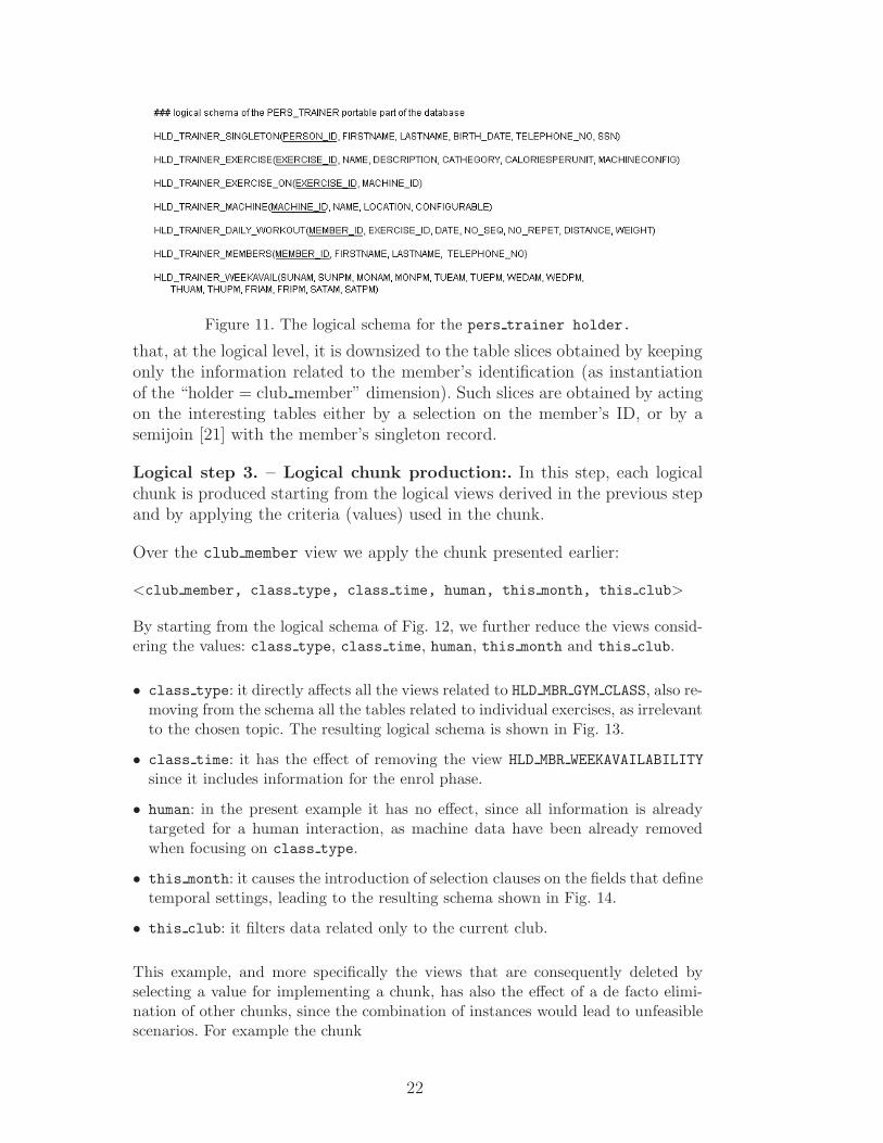
Figure 11. The logical schema for the pers trainer holder.
that, at the logical level, it is downsized to the table slices obtained by keepingonly the information related to the member’s identification (as instantiationof the “holder = club member” dimension). Such slices are obtained by actingon the interesting tables either by a selection on the member’s ID, or by asemijoin [21] with the member’s singleton record.
Logical step 3. – Logical chunk production:. In this step, each logicalchunk is produced starting from the logical views derived in the previous stepand by applying the criteria (values) used in the chunk.
Over the club member view we apply the chunk presented earlier:
<club member, class type, class time, human, this month, this club>
By starting from the logical schema of Fig. 12, we further reduce the views consid-ering the values: class type, class time, human, this month and this club.
• class type: it directly affects all the views related to HLD MBR GYM CLASS, also re-moving from the schema all the tables related to individual exercises, as irrelevantto the chosen topic. The resulting logical schema is shown in Fig. 13.
• class time: it has the effect of removing the view HLD MBR WEEKAVAILABILITYsince it includes information for the enrol phase.
• human: in the present example it has no effect, since all information is alreadytargeted for a human interaction, as machine data have been already removedwhen focusing on class type.
• this month: it causes the introduction of selection clauses on the fields that definetemporal settings, leading to the resulting schema shown in Fig. 14.
• this club: it filters data related only to the current club.
This example, and more specifically the views that are consequently deleted byselecting a value for implementing a chunk, has also the effect of a de facto elimi-nation of other chunks, since the combination of instances would lead to unfeasiblescenarios. For example the chunk
22
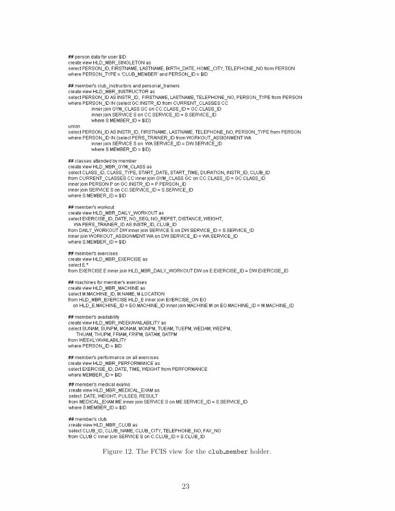
Figure 12. The FCIS view for the club member holder.
23
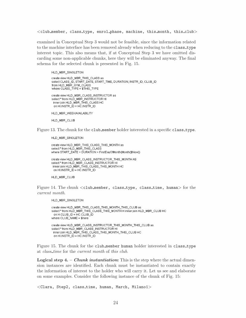
<club member, class type, enrol phase, machine, this month, this club>
examined in Conceptual Step 3 would not be feasible, since the information relatedto the machine interface has been removed already when reducing to the class typeinterest topic. This also means that, if at Conceptual Step 3 we have omitted dis-carding some non-applicable chunks, here they will be eliminated anyway. The finalschema for the selected chunk is presented in Fig. 15.
Figure 13. The chunk for the club member holder interested in a specific class type.
Figure 14. The chunk <club member, class type, class time, human> for thecurrent month.
Figure 15. The chunk for the club member human holder interested in class typeat class time for the current month of this club.
Logical step 4. – Chunk instantiation: This is the step where the actual dimen-sion instances are identified. Each chunk must be instantiated to contain exactlythe information of interest to the holder who will carry it. Let us see and elaborateon some examples. Consider the following instance of the chunk of Fig. 15:
<Clara, Step2, class time, human, March, Milano1>
24
This chunk will be hosted in the smart card of the club member Clara 2 , for theclass type Step2, in the March sessions of club Milano1. Here we can begin withnoticing two interesting points.
• The space dimension value “this club” has been instantiated to the “Milano1” cluband the time dimension value “this month” to “March”. Actually, this physicallyhappens “on the fly”, because the instantiation is based on an external informa-tion which is out of the designer’s control. This value is an input to the system assoon as some positioning device has been used, and, at the next synchronizationevent, the system will query the (central) database to obtain all the informationrelated to the month of March at the Milano1 club for this and also for the otherchunks that reside on Clara’s specific device. Here, the difference of time andspace w.r.t. the other dimensions becomes evident.
• In this chunk, not all the positions are instantiated: this, in its turn, may havetwo reasons:
· all the possible instances of the considered dimension value are interesting. Inthis case, creating one chunk for each instance only generates a useless combi-natorial explosion of the already numerous chunk population. This is the caseof the value human for the “interface” dimension, where the format of on-cardinformation carried by each human (especially because we are in the case ofclass-related information) is the same. Instead, in individual exercises, it mightbe an application requirement to have different human interfaces, for examplefor blind people.
· the dimension value cannot be further specialized: this is the case of the “sit-uation” dimension, where the class time value does not lend itself to be-ing detailed. Indeed, in this application a further specialization of such valuesseems to make little sense; for instance introducing for the class time schemaa MondayAM value to downsize the amount of data to be stored on the SmartCard seems to give a too restricted view of the available information.
Anyway, note that in this paper we decided to apply some form of Occam razor,by limiting only to three the number of generalization/specialization levels thatcan be analyzed, i.e. dimension → dimension value → value instance. Indeed,as already said, the application can lend itself to any number of levels, thusgenerating a whole ontology. Further investigations on this subject are part offuture research.
To summarize, chunk instantiation can be performed by assigning each position avalue that will normally be (or be derivable from) one (or more) value(s) in thedomain of the attribute corresponding to that dimension value; for example, Step2is the type of a course in the GYM CLASS table, or Cyclette A1 might be aninstance (id) of a machine in the MACHINE table, if deemed significant to have acomplete view of the various body building machines.
2 Note that this is a nickname we use for the sake of readability; in the real appli-cation this should be replaced by Clara’s id.
25
Logical step 5. – Final chunk instance collection, to produce the specificVSDB. At this point, all the instantiated chunks defined as views are collectedand materialized to form each specific holder’s initial VSDB. During the VSDB lifethe view definitions will be used to update the data locally stored in the tables, atsynchronization times. Consider, as an example, the member holder attending a clubin another city for a certain amount of time; the first time the holder synchronizesthe portable VSDB all stored data depending on this club will be updated to referto the current club he/she is attending. Further considerations on synchronizationare discussed in Section 6.
Logical step 6. – Access authorization views and grants. As we pointed outin Section 2, this dimension is used to define access rights to the database objectsin the global schema. With respect to the logical schema of Fig. 12, the analysisof the data ownership dimension can lead to the privileges definition reported inFig. 16. This privilege schema allows everybody to look at Person information, butonly the club administrator to modify it and to grant other people this privilege.Any club member can look at his/her own Daily Workout and Execise cat, butonly the pers trainer, or a person he/she has granted this privilege to, can modifythem; notice that the pers trainer can also update the performance of any singleclub member, through the HLD MBR PERFORMANCE view. All the remaining entrieshave similar meanings.
Given the privilege definition schema, we can instantiate it for the chunk
<club member, exercise cat, class time, human, *, *>
in order for the pers trainer to allow a colleague to modify the exercise schedulefor a club member (Fig. 17).
Note that the two GRANT clauses of Fig. 17 apply an abuse of SQL notation, sincebetween angled brackets we find the result of a query on the card resident database.It is used here to show that the privilege beneficiaries are parametric, and must bederived from card resident data.
5 Logistic phase
At this point of the design methodology the technological characteristics of thememory support device (Flash EEPROM) are taken into account to determine theamount of data to be held on the portable device, to minimize power consumption,to optimize performance and to maximize Flash memory endurance. We discuss thematter briefly here for the sake of self-containment; all the details of the method-ological approach to the logistic phase can be found in [13].
The logistic phase aims at determining the best physical data structures for storingthe relations to be held on the portable device, based on the relation characteristicssuch as number/type/dimension of the fields, existence of ordering field(s), expected
26
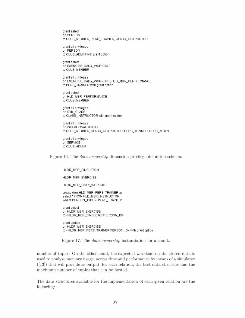
Figure 16. The data ownership dimension privilege definition schema.
Figure 17. The data ownership instantiation for a chunk.
number of tuples. On the other hand, the expected workload on the stored data isused to analyze memory usage, access time and performance by means of a simulator([13]) that will provide as output, for each relation, the best data structure and themaximum number of tuples that can be hosted.
The data structures available for the implementation of each given relation are thefollowing:
27
• heap relation: limited number of tuples, i.e. less than 10; examples of the FCISviews that might be materialized by using this data structure are HLD INSTR SINGLETON,HLD MBR SINGLETON, HLD MBR INSTRUCTOR.
• Sorted relation: number of tuples in the order of the hundreds, sorted on one ormore attribute(s); an example in the FCIS is the table used to store the members’weekly availability on the class instructor’s card in the enrol phase situation.
• Circular list relation: number of tuples in the order of the hundreds, a fixed sizerelation storing log-like entries; as soon as an insert request exceeds the maximumsize chosen for the table, the “oldest” (or “farthest”) record is deleted to makeroom for the next one to be inserted; we elaborate a little more on this datastructure below.
• Generic relation: not belonging to any of the previous categories, whose size makesthe use of indexes mandatory for the sake of efficiency; the designer should avoidto use such a relation, but, if necessary, it can be implemented by means of adhoc indexed structures [16].
The allocation policy can take into account the envisaged table size, but nothingcan be done at run time to keep the number of tuples under control; however, assaid in Section 2, priority levels assigned to the various chunks can be used forswapping table contents to and from the (central) database. Moreover, arbitraryrun time cardinality control can be automatically enforced on the relations of thethird type, recording log-like information, by keeping the number of locally storedrecords below a predefined number. In particular, reductions based on the kantiandimensions may be advisable.
Temporal attributes can be used to resize card resident data; for instance, oftenusers may be interested in data within a limited time interval and ordered by time(e.g. the latest month’s performance).
For example, the view HLD MBR PERFORMANCE can be further refined in the logis-tic design phase by adding an ORDER BY DATE clause, plus a constraint thatlimits them to the most recent N, where N is the predefined number of entries thematerialized view must contain.
When dealing with spatial attributes, things become more complex; in this casethe view must be based on the current reference location and on a variable sort-ing predicate, related to location information. Also here additional constraints canbe inserted, e.g. when using a GPS location finder, a view containing interestingrestaurants could be refined by adding:
...WHERE address NEAR self.location
and a further constraint should limit the tuples to the N whose address has beencomputed as the closest to self.location. Of course in this case the closest restaurantsmust be computed on the fly, at synchronization time.
28
Log like relations can be used also for limiting relation size by exploiting otherattributes than time and space. For instance the logistic designer may act by addingan order-by clause:
ORDER BY COST | NAME | START_TIME
and use analogous constraints to those illustrated before to reduce the entries tothe N cheapest, or to the first n names in the alphabet, etc.
A prototype tool has been developed to support the designer with the proposeddesign methodology. The tool, developed in Java [17], follows the steps we identified,providing means to define the conceptual database schema, the dimensions and thechunks.
6 Synchronization issues
Two levels of synchronizations need be taken into account in this scenario: (1) in-stance level synchronization, needed because of data modifications occurred eitheron the portable device or on the fixed database, and (2) schema level synchroniza-tion, needed because the database schema available on the portable device mustchange due to context changes.
As far as instance level synchronization is concerned, problems typical of distributeddatabases arise, when either of the following situations arises:
• data is locally modified, on the portable device, and the modified information hasto be propagated to the fixed database;
• data is modified on the fixed database and the portable device data need beupdated accordingly.
Since this synchronization issue is not affected by any specific aspect related tothe fact that a “small” portion of the database is available on the portable device,mechanisms typically used for distributed systems can be adopted here. As a resultwe focused our attention on the problems related to the fact that the distributedenvironment may be unavailable at a given time due to mobility. For the purposea one-phase commit protocol has been studied [18], to guarantee that distributedtransactions can be correctly carried out without loss of information or data incon-sistency between the portable device(s) and the fixed database.
A different scenario occurs when a schema level synchronization is possibly needed:this situation may arise when another chunk is requested, or when the “context”(here(), now(), ...) changes and the portable database has to change accordingly.In the best case, a change of value in the instance of the chunk may not require achange in the database schema, but in the worst case a different schema may be
29
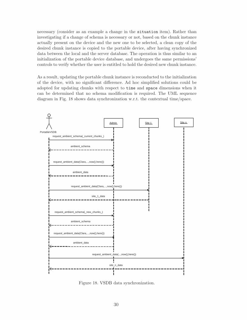
necessary (consider as an example a change in the situation item). Rather thaninvestigating if a change of schema is necessary or not, based on the chunk instanceactually present on the device and the new one to be selected, a clean copy of thedesired chunk instance is copied to the portable device, after having synchronizeddata between the local and the server database. The operation is thus similar to aninitialization of the portable device database, and undergoes the same permissions’controls to verify whether the user is entitled to hold the desired new chunk instance.
As a result, updating the portable chunk instance is reconducted to the initializationof the device, with no significant difference. Ad hoc simplified solutions could beadopted for updating chunks with respect to time and space dimensions when itcan be determined that no schema modification is required. The UML sequencediagram in Fig. 18 shows data synchronization w.r.t. the contextual time/space.
PortableVSDB
Admin
request_ambient_data(Clara,...,now(),here())
request_ambient_schema(_current_chunks_)
request_ambient_data(Clara,...,now(),here())
Site 1 Site n
ambient_data
ambient_schema
site_1_data
request_ambient_data(...,now(),here())
site_n_data
request_ambient_schema(_new_chunks_)
ambient_schema
request_ambient_data(Clara,...,now(),here())
ambient_data
Figure 18. VSDB data synchronization.
30
7 Concluding Remarks and Future work
In this paper we have presented a methodology for designing small databases tobe hosted by mobile/portable devices. Given the reduced resources available onportable systems and the quest for context aware applications, our approach aimsat defining and selecting the data to be locally stored on a portable device, to bereadily available and updated with respect to the user’s context. As already pointedout elsewhere in the paper, this research entails a number of other future directions:
• removing the global schema hypothesis, in a scenario where the mobile devicejoins in a (semi)unknown Information System whose data resources is interestedin sharing; this direction will surely include the use of semi-structured data modelsfor representing and communicating data between the mobile device and theinformation system it joins [19].
• Further investigations on the various ontological levels the dimensions can be de-tailed into, along with the study and use of possible dependencies for automaticalchunk discarding.
• Further work on the VSDB system prototype, studying appropriate versions ofthe classical ACID properties.
Acknowledgment
We thankfully acknowledge many helpful discussions on the context dimensions withAugusto Celentano, Elisa Quintarelli and Fabio Salice, plus the numerous studentswho contribute to case studies for our methodological considerations.
References
[1] S. Banerjee et Al., Rover: Scalable location-aware computing, IEEE Computer35 (10) (2002) 46–53.
[2] U. Dayal and P. Bernstein On the updatability of relational views, in:Proceedings of the Fourth International Conference on Very Large Databases,West Berlin, Germany, September 1978.
[3] Langerak, L., View updates in relational databases with an independent scheme,ACM Transactions on Database Design, 15:1, March 1990.
[4] D. L. Lee, W.-C. Lee, J. Xu and B. Zheng, Data management in location-dependent information services, IEEE Pervasive Computing 1 (3) (2002) 65–72.
31
[5] H. Mohanty, Active and nomadic transactions in mobile databases, in: ADBIS-DASFSAA Symposium, 2000, pp. 99–107.
[6] B. N. Schilit, J. Trevor, D. M. Hilbert and T. K. Koh, Web interaction usingvery small internet devices, Computer 35 (10) (2002) 37–45.
[7] J. Sutherland and W.-J. van den Heuvel, Enterprise application integration andcomplex adaptive systems, Communications of the ACM 45 (10) (2002) 59–64.
[8] M. Olson, Selecting and implementing an embedded database system, IEEEComputer 33 (9) (2000) 27–34.
[9] S. Ceri and G. Pelagatti, Distributed Databases, McGraw-Hill, Inc, 1984.
[10] M. T. Ozsu, P. Valduriez, Distributed and parallel database systems, ACMComputing Surveys 28 (1) (1996) 125–128.URL citeseer.nj.nec.com/ozsu96distributed.html
[11] C. Bolchini, F. A. Schreiber, L. Tanca, A context-aware methodology for verysmall data base design, SIGMOD Rec. 33 (1) (2004) 71–76.
[12] C. Bolchini, F. A. Schreiber, Smart card embedded information systems: amethodology for privacy oriented architectural design, Data and KnowledgeEngineering 41 (2-3) (2002) 159–182.
[13] C. Bolchini, F. Salice, F. A. Schreiber and L. Tanca, Logical and physical designissues for smart card databases, ACM Transactions on Information Systems21 (3) (2003) 1046–8188.
[14] I. Kant, Critique of the Pure Reason, Macmillan Press Ltd, 1787.URL http://www.arts.cuhk.edu.hk/Philosophy/Kant/cpr/
[15] F. A. Schreiber, Is time a real time: an overview of time ontology in informatics,in: A. Halang, A. D. Stoyenko Eds.- Real Time Computing - Springer NATOASI Series, Vol 127, 1994, pp. 283–307.
[16] C. Bobineau, L. Bouganim, P. Pucheral, P. Valduriez, PicoDBMS: Scaling downdatabase techniques for smart card, in: Proc. 26th Int. Conf. on Very LargeDatabases, 2000, pp. 11–20.
[17] C. Berg, Advanced Java 2 Development for Enterprise Applications 2nd Edition,Prentice-Hall, 2000.
[18] C. Bolchini, A. Lazaric, C. A. C. Pascali, S. Sceffer, F. A. Schreiber, L. Tanca,Implementation of a Distributed Commit Protocol on the PoLiDBMS, RapportoMAIS WP. 5.2, 2004.
[19] A. Celentano, F. A. Schreiber, L. Tanca, Requirements for Context-DependentMobile Access to Information Services, Proceedings of Tenth InternationalWorkshop on Multimedia Information Systems, College Park (MA) 2004, pp.60-65.
[20] C. Batini, S. Ceri, S. B. Navathe, Conceptual Database Design: An Entity-Relationship Approach, Benjamin/Cummings, 1992.
32

[21] R. Elmasri, S. B. Navathe, Fundamentals of Database Systems, Addison-Wesley,2004 (fourth edition).
33