A METHOD FOR THREE DIMENSIONAL TOLERANCE ...
11
A METHOD FOR THREE DIMENSIONAL TOLERANCE ANALYSIS AND SYNTHESIS APPLIED TO COMPLEX AND PRECISE ASSEMBLIES Frederic Germain, Dimitri Denimal, Max Giordano Symme Lab. University de Savoie, 5 chemin de Bellevue 74940 Annecy le Vieux {fredericgermain, dimitri.denimal,max.giordano}@univ-savoie.fr Abstract The tolerancing process for precise mechanical systems in a context of short or long run in industrial production requires a rational method from the speci- fication of the functional requirements until the final products are checked. Nowa- days the optimization of the tolerances is generally carried out empirically. Com- promises must be made between the fiinctional requirements in the design process and the manufacturing step. The limits of accuracy imposed by the process must be taken into account. The need for a rational method is particularly necessary for new products in the field of traditional mechanisms as well as of micromechanics or even of micro-systems. In the design process, in the case of an assembly, the ftinc- tional requirements must be defined in geometrical terms, in order to satisfy the customer requirements. Then, these geometrical requirements must be translated in- to specifications on the various parts so that on the one hand the assembly can be carried out under well defined conditions and on the other hand, after assembly, the functional requirements are strictly respected. This transfer of specifications with creations of new specifications of the assembly requires a three-dimensional geo- metrical analysis taking into account the geometrical deviations- form defects, posi- tion and orientation- and size deviations. Clearances in the assemblies also will in- tervene. They are necessary to ensure the mechanical motions but also to compensate for variations of geometry in the case of hyper constrained assemblies. In the phase of industrialisation, the geometrical and dimensional tolerances will be necessary for the choice of machines, for manufacturing planning process and for the measurement processes during the production but also for the final quality control of the parts and of the system. The methods of assemblies are also strongly conditioned by the functional requirements. Please use the following format when citing this chapter: Germain, F., Denimal, D., Giordano, M., 2008, in IFIP International Federation for Information Processing, Volume 260, Micro-Assembly Technologies and Applications, eds. Ratchev, S., Koelemeijer, S., (Boston: Springer), pp. 55-65.
-
Upload
khangminh22 -
Category
Documents
-
view
0 -
download
0
Transcript of A METHOD FOR THREE DIMENSIONAL TOLERANCE ...

A METHOD FOR THREE DIMENSIONAL TOLERANCE ANALYSIS AND SYNTHESIS APPLIED TO COMPLEX AND PRECISE ASSEMBLIES
Frederic Germain, Dimitri Denimal, Max Giordano
Symme Lab. University de Savoie, 5 chemin de Bellevue 74940 Annecy le Vieux {fredericgermain, dimitri.denimal,max.giordano}@univ-savoie.fr
Abstract The tolerancing process for precise mechanical systems in a context of short or long run in industrial production requires a rational method from the specification of the functional requirements until the final products are checked. Nowadays the optimization of the tolerances is generally carried out empirically. Compromises must be made between the fiinctional requirements in the design process and the manufacturing step. The limits of accuracy imposed by the process must be taken into account. The need for a rational method is particularly necessary for new products in the field of traditional mechanisms as well as of micromechanics or even of micro-systems. In the design process, in the case of an assembly, the ftinc-tional requirements must be defined in geometrical terms, in order to satisfy the customer requirements. Then, these geometrical requirements must be translated into specifications on the various parts so that on the one hand the assembly can be carried out under well defined conditions and on the other hand, after assembly, the functional requirements are strictly respected. This transfer of specifications with creations of new specifications of the assembly requires a three-dimensional geometrical analysis taking into account the geometrical deviations- form defects, position and orientation- and size deviations. Clearances in the assemblies also will intervene. They are necessary to ensure the mechanical motions but also to compensate for variations of geometry in the case of hyper constrained assemblies. In the phase of industrialisation, the geometrical and dimensional tolerances will be necessary for the choice of machines, for manufacturing planning process and for the measurement processes during the production but also for the final quality control of the parts and of the system. The methods of assemblies are also strongly conditioned by the functional requirements.
Please use the following format when citing this chapter:
Germain, F., Denimal, D., Giordano, M., 2008, in IFIP International Federation for Information Processing, Volume 260, Micro-Assembly Technologies and Applications, eds. Ratchev, S., Koelemeijer, S., (Boston: Springer), pp. 55-65.
56 A Method for Three Dimensional Tolerance Analysis and Synthesis applied to Complex and Precise Assemblies
1 References to related works and literature
Many works about dimensional and geometrical tolerances are presented in literature, but few of them offer a general method for three dimensional tolerance analysis and synthesis. The synthesis can be broken down into two parts: the qualitative and quantitative aspects. Initially, the question is to determine which surfaces are to be toleranced, which kinds of tolerances must be used, to define the references or datum reference frames. The quantitative synthesis consists in calculating the values to be assigned to the various tolerances in order to guarantee the functional requirements. Two approaches are possible: worst case tolerancing and statistical tol-erancing. O. W. Salomons presents special software to help the designer to analyse and specify the tolerances [1], [2]. This tool is based on the concept of TTRS (Technologically and Topologically Related Surfaces) suggested by A. Clement [3] and taken again by other researchers [4]. In this method starting from the fiinctional technological analysis the functional surfaces of the parts are linked between each other creating a binary tree. Several solutions are often possible and no rule is given to associate various surfaces. It seems that it is only the ability of the designer that allows one to choose the associate parts. B. Anselmetti also proposes an approach based on the expertise of the designer and he defines a named method "method CLIC". The rules, which lead to a choice of specifications, are not always justified but they give a solution in conformity with the ISO standards or with the ASME standard [5]. He shows the importance of the assembly method for the judicious choice of the tolerances and the datum systems under the qualitative aspect. On the other hand the calculation of the tolerances is based on the traditional chains of dimensions. The 3D problem is translated to a one-dimensional problem thanks to the concept of direction of analysis but the variations of orientation remain difficult to take into account. This last concept is also presented by L. Laperriere [6]. The concept of "Jacobean torsor" in fact is the same concept as the small displacements tor-sor used to model the variations of position and orientation.
In the statistical approach to analysing tolerances, generally one considers a functional condition "y", fimction of parameters characteristic of the geometry of parts xi: y=f(xi). It is assumed that each of these parameters is affected by independent dimensional tolerances. One distinguishes the analytical methods, which consists in calculating statistical characteristics of the variable y while those of variables xi are known and the simulation of Monte-Carlo which consists in generating a great number of random events. The first often encounters complex mathematical difficulties except in the particular case of linear functions. The second is greedy in computing times to obtain accurate results.
The analytical method uses the first order development in the vicinity of the configuration targets y=f(xiO)+I 5F/^i(xi-xiO). If the variables xi are random independent variables of average m(xi) and variance v(xi), then the mean value and the variance of the y variable are obtained by m(y)= f(m(xi)) and v(y)= I (9F/^i)^ v(xi). S. Nigam and J. Turner present a review of the statistical approaches for the analysis of tolerances starting from this parameterised form [7]. C. Clancy and K.

F. Germain, D, Denimal, M. Giordano 57
Chase propose a development with the second order for the analysis of tolerances of the assemblies in the nonlinear cases and use the statistical moments until order 4 [8]. The simulation of Monte-Carlo is more often used. It applies even if the relation is not linear and for any type of laws of distribution of the variables. Let us quote for example R.J. Gerth, W. Mr. Hancock who use the method of Monte-Carlo on a parameterized one and three dimensional model and use the data of manufacturing process to adapt the choice of the tolerances [9].
2 The research method
The method suggested here is based on some tools to implement in a systematic process and generally applicable to the majority of the mechanical systems, more or less complex assemblies and mechanisms. The stages are as follows:
- First the functional requirements of the assembly must be defined in geometrical terms.
- Secondly the qualitative tolerances of the parts are built in accordance with these requirements.
- Then the relations between the tolerances of the parts and the assembly requirement are established.
- Finally the values of the tolerances can be analysed or optimised.
Before detailing each of these steps, an example is presented that will be used as a discussion thread with the course of the method. Each step will be applied to the example and will enable to follow the logic of the method without losing its generic aspect. It is about a double hydraulic cylinder permitting to operate a shutter in an airplane. The cylinder acts in a classical mechanism with four principal solids according to the scheme fig.la. The cylinder is double for safety conditions. Two independent hydraulic systems feed the two bodies so that in the event of escape in a circuit or one body, the other cylinder can still control the movement.
2.1 Functional requirements of the assembly in geometrical terms
In a general way a functional requirement is expressed by the acceptable limits of a geometric feature compared to another element belonging to the same part or another part of the mechanism or compared to a reference datum system built from several geometric features of the parts. One understands by geometric feature a particular point, a set of part surface points or an element built from a surface, the axis of a cylinder for example. Thus, the tolerances can be the allowed limits of a parameter (distance or angle) or can be a tolerance zone. The ISO standards on geometrical specification of products (GPS) can be extended to the functional conditions of an assembly.
58 ^ Method for Three Dimensional Tolerance Analysis and Synthesis applied to Complex and Precise Assemblies
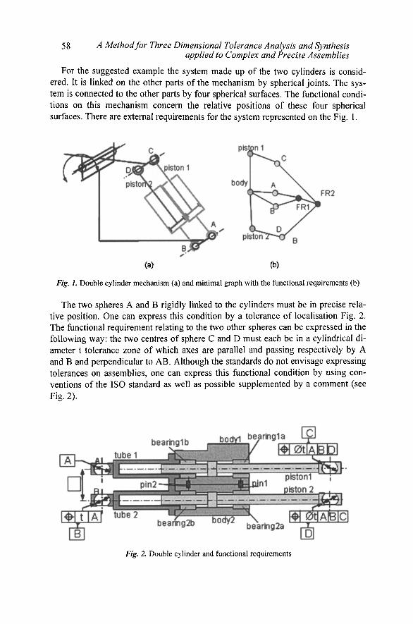
For the suggested example the system made up of the two cylinders is considered. It is linked on the other parts of the mechanism by spherical joints. The system is connected to the other parts by four spherical surfaces. The functional conditions on this mechanism concern the relative positions of these four spherical surfaces. There are external requirements for the system represented on the Fig. 1.
(a) (b)
Fig, 1. Double cylinder mechanism (a) and minimal graph with the functional requirements (b)
The two spheres A and B rigidly linked to the cylinders must be in precise relative position. One can express this condition by a tolerance of localisation Fig. 2. The functional requirement relating to the two other spheres can be expressed in the following way: the two centres of sphere C and D must each be in a cylindrical diameter t tolerance zone of which axes are parallel and passing respectively by A and B and perpendicular to AB. Although the standards do not envisage expressing tolerances on assemblies, one can express this functional condition by using conventions of the ISO standard as well as possible supplemented by a comment (see Fig. 2).
Fig, 2 Double cylinder and functional requirements

F. Germain, D. Denimal, M. Giordano 59
2.2 Qualitative aspect for tolerances
The problem is to define the dimensional and geometrical tolerances parts under qualitative aspect. The method to carry out the transfer of specifications under the qualitative aspect is based on graph representations presented in [10]. Two kinds of specifications then will appear: those which allow for carrying out the joints with given conditions of assembly and those which make it possible to guarantee the functional requirements after assembly. The kinematical graphs, the contact graphs and the tolerance graphs are imbricated graphs, which allow the qualitative synthesis even for complex cases comprising tens of surfaces of contact. In a kinematical graph, the vertices of the graph represent the parts and the edges are the joints. They are used for example for a kinematical or dynamic study. In graphs of contact, each vertex represents a Cartesian frame associated either with a contact surface, or built from several surfaces, or it is an arbitrary reference frame attached to each part. The graph edges characterise the geometrical deviation between reference frames in comparison with a perfect theoretical configuration of reference. There are two types of edges: between the reference frame of the same part, they characterise the geometrical deviations due to the manufacturing defects and surface of the joints, which characterise the possible contacts and gaps. The graphs of tolerance rise from the graphs of contact. The edges are oriented and enable to represent the toleranced surfaces and the datum system used form geometrical tolerances. These various graphs can be simplified or developed as a whole or locally. The development of the graph on a local level permits to analyze in detail the realization of a joint and the influence of a functional requirement over the feature of this joint. Specifications GPS ISO constitute an efficient tool for the representation of the tolerances because it is closed to the fimctional needs. One will define in this stage the toleranced surfaces, the surfaces or group of surfaces to be taken as a datum, the type of necessary tolerances: form orientation, localization or size.
Fig. 3, Contact graph of the double cylinder

60 ^ Method for Three Dimensional Tolerance Analysis and Synthesis applied to Complex and Precise Assemblies
Let us take again the example of the double cylinder. On the one hand, the minimal kinematical graph, the more possible simplified is represented Fig.lb. The external functional conditions were represented. On the other hand in the complete graph above Fig. 3, all the contacts and all the parts appear. From this graph, one can extract sub-graphs representing the parts or the joints (closed curves in Fig. 3).
Fig. 4, Sub-graph for the tube 1, graph of the tolerances and standardized specifications
From this graph one carries out two types of simplifications: - the joints in parallels are replaced by only one equivalent joint, the assembly requirement generate tolerances between the contact surfaces of the joint. The surfaces can be ordered, a priority surface will be a datum for the tolerance of another element. (Fig. 4). - the joints in series are replaced by only one joint, the fimctional requirement implies tolerances on the intermediate part (Error! Reference source not found.). - two parts with no relative motion are replaced by one equivalent part. Thus gradually, one passes from the graph Fig. lb to the graph Fig. 3 by generating the geometrical specifications on each part.
Fig. 5. Tolerance scheme for intermediate part

F. Germain, D. Denimal, M. Giordano 61
2.3 The quantitative step
This consists in establishing the relations between the data that characterize the specifications of the parts, and the variable that characterize the functional requirements. These relations can be established either starting from the worst case approach or according to a more realistic statistical approach in a context of inter-changeability and industrial production in series. The geometrical variations of orientation and position are characterised by small displacements torsors. A linear approximation of the angular deviations supposed small, leads to representing the rigid displacement by a torsor. The deviation of a surface will thus comprise three angular components and three linear components of displacement for a particular point and following the three orthogonal directions of the frame. According to the statistical approach, these relations require us to know a priori or to impose data relating to dispersions on the geometrical characteristics in production. The geometrical deviations are represented by the components of the small displacements torsors. They are characterised by an average vector and a covariance matrix.
In the case of the functional requirement results from a simple stack up tolerances it is easy to compute the mean vector and the covariance matrix of the resulting deviation torsor which is the sum of the torsors component by component. It is the traditional chains of dimensions method extended to the three dimensions.
When clearances in the joints intervene, one distinguishes a resulting deviation torsor and a resulting clearance torsor. The resulting deviation torsor is determined as in the preceding case without taking into account the clearances. Its components are random variables. The resulting clearance torsor is unspecified. The limits of his components are fixed by real dimensions which are random variables. For example, for a shaft in a boring, the limits of the displacements permitted by the clearance depend on the two diameters. One calls clearance domain the sets of displacements limited by these random variables. For a given set of parts, the sum of the clearance domain and the deviation torsor is called shifted clearance domain. For a whole of parts, one will be able to then determine by the Monte Carlo method the whole of the possible variations due to the deviations and the clearances.
For joints connected in parallel, and a given assembly, the intersection of all the shifted clearance domains gives the resulting deviation after assembly from each branch in parallel. The assembly is possible only if this intersection exists. One will there obtain the dispersion of the variations of positions after assembly by taking into account the geometrical defects and the clearance by the Monte Carlo method. One studies first the assembly of the two bodies. The tolerances of the diameters of the two pins-holes are given in table 1. It is supposed that the values of dimensions and geometrical defects in the manufactured production of the parts are independent random variables centred on their target value. It is also supposed that the distribution is Gaussian with a standard deviation equals to the sixth of the tolerance.

62 ^ Method for Three Dimensional Tolerance Analysis and Synthesis applied to Complex and Precise Assemblies
Pin-hole 01OH6/h6 mean tol g
hole 01OH6 10.0045 9 jam 1.5 ^m
pin 01Oh6 9.9955 9 im 1.5 |am
Table L Fit of pin-hole
The tolerances of localisation are tl=0.01 mm (see Fig. 6). Fig. 7 gives the distribution of the variations of the relative position of the two bodies after assembly. It is noticed that in the worst case the assembly is not possible without constraint, whereas nearly 97.5% of the assemblies are possible according to the assumptions of statistical distribution. In 95% of the cases, the defect of setting in position of the two bodies does not exceed 9 microns. One hundred thousand samples were carried out for this simulation.
Fig. 6. Qualitative tolerance specification for body 2.
Fig. 7. Histogram for the gap or subconstraint in the pin-hole assembly.
F. Germain, D. Denimal, M. Giordano 63
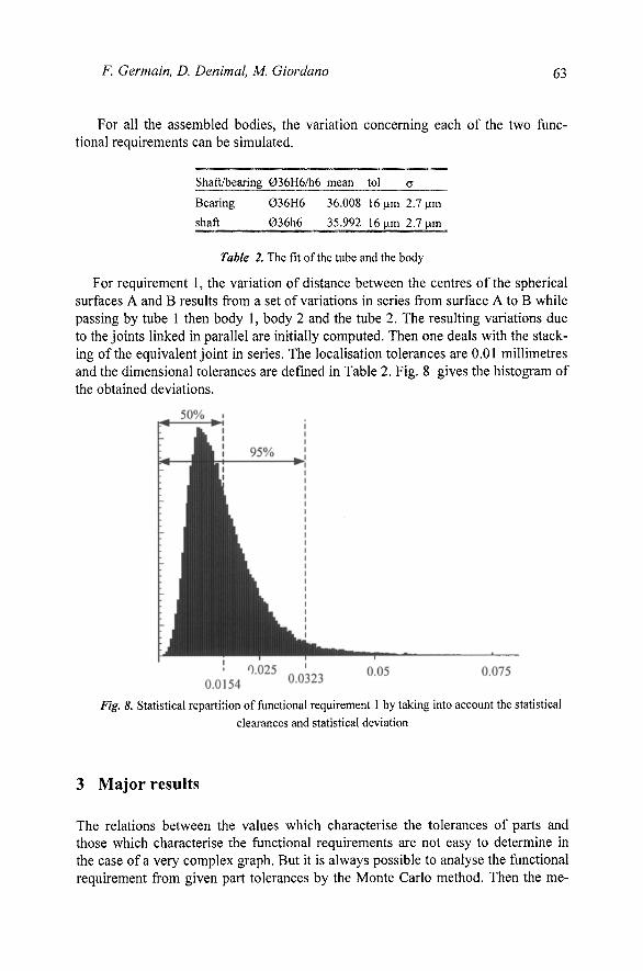
For all the assembled bodies, the variation concerning each of the two functional requirements can be simulated.
Shaft/bearing 036H6/h6 mean tol g
Bearing 036H6 36.008 16fam 2.1 \xm
shaft 036h6 35.992 16|Lim 2.7 im
Table 2. The fit of the tube and the body
For requirement 1, the variation of distance between the centres of the spherical surfaces A and B results from a set of variations in series from surface A to B while passing by tube 1 then body 1, body 2 and the tube 2. The resulting variations due to the joints linked in parallel are initially computed. Then one deals with the stacking of the equivalent joint in series. The localisation tolerances are 0.01 millimetres and the dimensional tolerances are defined in Table 2. Fig. 8 gives the histogram of the obtained deviations.
Fig, 8. Statistical repartition of functional requirement 1 by taking into account the statistical clearances and statistical deviation
3 Major results
The relations between the values which characterise the tolerances of parts and those which characterise the functional requirements are not easy to determine in the case of a very complex graph. But it is always possible to analyse the functional requirement from given part tolerances by the Monte Carlo method. Then the me-
64 ^ Method for Three Dimensional Tolerance Analysis and Synthesis applied to Complex and Precise Assemblies
thod permits us to guide a synthesis of tolerance in an objective of optimisation, i.e. choice of the tolerances which guarantee the functional requirement but without over-quality. The tools of assistance to simulation make it possible to define the structure of the mechanism by the graphs. After the qualitative determination of the tolerances defined automatically starting fi-om the decomposition of the contact graph, one will be able to introduce the values of the adjustments and the tolerances defined a priori. The computing of geometrical stack up tolerances and the combination of the motions due to the clearances allow us to check the fitting and to see the influence of the various parameters when regenerating the computing after modifying the data. An example of a hydraulic cylinder with two bodies assembled by two axes is investigated. The dispersions obtained after assembly enable designers to check the choices of the fits and the geometrical tolerances and to question the technological choices in order to optimise the system before prototyping.
The method suggested provides an important benefit in comparison with the conventional methods of analysis. On the one hand one proposes here a method of synthesis of the tolerances under the qualitative aspect which allows a coherent quantitative analysis, whereas no general method of synthesis does exist. In addition, the geometrical defects such as coaxiality, symmetry, etc, and the tolerance size are taken into account in our model. Finally the majority of the models of simulation are applied on mechanisms with particular and simple structures: open or closed loops while the method suggested here is more general and can be applied to complex mechanisms.
References
1. O.W. Salomons, and al, A computer aided tolerancing tool I : tolerance specification, Computers in Industry Vol 31 1996 pp. 161-174
2. O.W. Salomons, and al., A computer aided tolerancing tool II: tolerance analysis. Computers in Industry Vol 31 1996 pp. 175-186
3. A.Clement, A. Riviere and M. Temmerman Cotation tridimensionnelle des systemes me-caniques, theorie et pratique PYC Edition, 1994
4. ADesrochers and A. Clement A dimensioning and tolerancing assistance model for CAD/CAM systems, International Journal of Advenced Manufacturing Technology, Vol.9, 1994, pp.352, 361.
5. B. Anselmetti, K. Mawussi, Tolerancement fonctionnel d'un mecanisme : identification de la boucle de contacts, IDMME, May 14-16 2002 Clermont-Ferrand, France.
6. L. Laperriere, W. Ghie, A. Desrochers, Projection of Torsors : a Necessary Step for Tolerance Analysis Using the Unified Jacobian Torsor Model. 8^ CIRP International Seminar on Computer Aided Tolerancing, April 28-29, Charlotte, North Carolina, USA.
7. S. D. Nigam and J. U. Turner, Review of statistical approaches to tolerance analysis, Computer-Aided Design, Vol 27, N° 1, pp.6-15, 1995.
8. C.G ; Glancy, K. W. Chase, A second-order method for assembly tolerance analysis, Proceedings of the ESME Design Engineering Technical Conferences, sept. 12-15, 1999, Las Vegas, Nevada.
F. Germain, D. Denimal, M. Giordano 65
9. R. J. Gerth, W. M. Hancock, Computer aided tolerance analysis for improved process control, in Computer & Industrial Engineering, Vol. 38, 2000, pp. 1-19.
10. P Hernandez, M Giordano, G Legrais, A new method of design integrated tolerancing, 14th CIRP 2004 Cairo, Egypt.
11. M. Giordano, E. Pairel, P. Hernandez, Complex Mechanical Structure Tolerancing by Means of Hyper-graphs, in Models for Computer Aided Tolerancing in Design and Manufacturing, J.K. Davidson Editor 2007, Springer, pp. 105-114.