A method for calculating the displacements of a powrtrain and mounts in a powertrain mounting system...
14
A method for calculating the displacements of a powertrain and mounts in a powertrain mounting system including torque struts under quasi-static loads Wen-Bin Shangguan 1,2 * and Da-Ming Chen 1 1 School of Mechanical and Automotive Engineering, South China University of Technology, Guangzhou, Guangdong, People’s Republic of China 2 State Key Laboratory of Automobile Dynamic Simulation, Jilin University, Changchun, Jilin, People’s Republic of China The manuscript was received on 11 July 2011 and was accepted after revision for publication on 7 September 2011. DOI: 10.1177/0954407011424816 Abstract: A modelling and calculation method for obtaining the displacements of the power- train’s centre of gravity (CG) and mounts in a powertrain mounting system (PMS) including the torque struts under a static or quasi-static load is presented. A new mount model that is modelled as three-dimensional (3D) springs with both a translational stiffness along each axis of its local coordinate system (LCS) and a rotational stiffness around each axis of its LCS is presented. Also a torque strut is a generic construction and is regarded as a massless rigid body with a mount at each of its two ends. The equation and the solution method for estimating the displacements of the powertrain’s CG and the mounts under a quasi-static load are developed when torque struts exist in a PMS. An example is given of the calculation and comparison of the displacements of the power- train’s CG and mounts in a generic PMS including a torque strut using both the method pro- posed in this paper and the conventional method published in the referenced papers. Keywords: automotive powertrain mounting system, torque strut, displacements of the powertrain’s centre of gravity and mounts, mount model with both a translational and a rotational stiffness 1 INTRODUCTION As transversely mounted and front-wheel-drive powertrains are widely used for cars [1–3], a torque strut is frequently used in this configuration of a powertrain mounting system (PMS) [4]. The config- uration of a transversely mounted powertrain and the structure of a torque strut are shown in Figs 1(a) and 1(b) respectively. A torque strut has two mounts: mount 1 is connected with the powertrain, and mount 2 is connected with the body or cradle. The two mounts can be rubber mounts or hydraulic mounts [5]. A torque strut is mainly used to control the rota- tional motion of the powertrain around the crank- shaft direction when the powertrain bears a large torque in the crankshaft direction or a large impact load in the vehicle’s longitudinal direction [4]. The advantage of a torque strut is that it provides linear stiffness only in the direction of P 1 P 2 , and torsional stiffness around the mount axis, where the points P 1 and P 2 are the centres of mount 1 and mount 2 respectively. Since the torque strut in a PMS is usu- ally installed in a horizontal plane (the line P 1 P 2 is in horizontal plane), the vertical stiffness that a tor- que strut provides to a PMS is greatly decreased, thus enhancing the isolation of a PMS. In designing a PMS, two basic strategies are used frequently. One strategy is to move the six natural frequencies of the powertrain rigid body modes away from the frequencies of the input sources, and to decouple the powertrain vibration in six *Corresponding author: School of Mechanical and Automotive Engineering, South China University of Technology, Guangzhou, Guangdong 510641, People’s Republic of China. email: [email protected] 634 Proc. IMechE Vol. 226 Part D: J. Automobile Engineering
Transcript of A method for calculating the displacements of a powrtrain and mounts in a powertrain mounting system...

A method for calculating the displacements of apowertrain and mounts in a powertrain mountingsystem including torque struts under quasi-static loadsWen-Bin Shangguan1,2* and Da-Ming Chen1
1School of Mechanical and Automotive Engineering, South China University of Technology, Guangzhou, Guangdong,
People’s Republic of China2State Key Laboratory of Automobile Dynamic Simulation, Jilin University, Changchun, Jilin, People’s Republic of China
The manuscript was received on 11 July 2011 and was accepted after revision for publication on 7 September 2011.
DOI: 10.1177/0954407011424816
Abstract: A modelling and calculation method for obtaining the displacements of the power-train’s centre of gravity (CG) and mounts in a powertrain mounting system (PMS) includingthe torque struts under a static or quasi-static load is presented. A new mount model that ismodelled as three-dimensional (3D) springs with both a translational stiffness along each axisof its local coordinate system (LCS) and a rotational stiffness around each axis of its LCS ispresented. Also a torque strut is a generic construction and is regarded as a massless rigidbody with a mount at each of its two ends.
The equation and the solution method for estimating the displacements of the powertrain’sCG and the mounts under a quasi-static load are developed when torque struts exist in a PMS.An example is given of the calculation and comparison of the displacements of the power-train’s CG and mounts in a generic PMS including a torque strut using both the method pro-posed in this paper and the conventional method published in the referenced papers.
Keywords: automotive powertrain mounting system, torque strut, displacements of the
powertrain’s centre of gravity and mounts, mount model with both a translational and a
rotational stiffness
1 INTRODUCTION
As transversely mounted and front-wheel-drive
powertrains are widely used for cars [1–3], a torque
strut is frequently used in this configuration of a
powertrain mounting system (PMS) [4]. The config-
uration of a transversely mounted powertrain and
the structure of a torque strut are shown in Figs 1(a)
and 1(b) respectively. A torque strut has two
mounts: mount 1 is connected with the powertrain,
and mount 2 is connected with the body or cradle.
The two mounts can be rubber mounts or hydraulic
mounts [5].
A torque strut is mainly used to control the rota-
tional motion of the powertrain around the crank-
shaft direction when the powertrain bears a large
torque in the crankshaft direction or a large impact
load in the vehicle’s longitudinal direction [4]. The
advantage of a torque strut is that it provides linear
stiffness only in the direction of P1P2, and torsional
stiffness around the mount axis, where the points P1
and P2 are the centres of mount 1 and mount 2
respectively. Since the torque strut in a PMS is usu-
ally installed in a horizontal plane (the line P1P2 is
in horizontal plane), the vertical stiffness that a tor-
que strut provides to a PMS is greatly decreased,
thus enhancing the isolation of a PMS.
In designing a PMS, two basic strategies are used
frequently. One strategy is to move the six natural
frequencies of the powertrain rigid body modes
away from the frequencies of the input sources,
and to decouple the powertrain vibration in six
*Corresponding author: School of Mechanical and Automotive
Engineering, South China University of Technology, Guangzhou,
Guangdong 510641, People’s Republic of China.
email: [email protected]
634
Proc. IMechE Vol. 226 Part D: J. Automobile Engineering

directions for each vibration mode in the best way
possible [6–12]. Many methods can be used to
design mounts to meet the requirement of this strat-
egy [6–12]. The other strategy is to determine the
force versus displacement relation of a mount in its
local coordinate system (LCS) to limit the motion of
a powertrain under an external static or quasi-static
load [12–14]. Since the relation between the force
and the displacement of a mount in its LCS is usu-
ally non-linear, it is simplified as piecewise linear in
five ranges [13]. The stiffness and corresponding
displacement ranges in the force versus displace-
ment curve of a mount can be easily implemented
by the structural design of a mount.
One of the present authors and a co-worker [13]
developed a method for calculating the displace-
ments by simplifying the non-linear relation of the
force versus the displacement as piecewise linear in
five ranges. Swanson et al. [14] presented a method
to calculate the displacements of the powertrain’s
CG and mounts if the force versus displacement
relation of a mount in its LCS is linear and thus the
stiffness is constant. In reference [13], the mount is
modelled as three-dimensional (3D) springs with
only a translational stiffness along each axis of its
LCS. Also the assumption is made that there is no
torque strut in the PMS. The displacements can also
be estimated using the method proposed in refer-
ence [13] if a torque strut installed in a PMS is sim-
plified as one conventional mount that is connected
with the powertrain. However, this simplification
causes errors if the motion of the powertrain is not
small. When the powertrain undergoes a large
motion, the torque strut in a PMS can provide tor-
sional stiffness to a powertrain.
This study is the extension of previous work [13].
An enhancement of this paper with respect to refer-
ence [13] is that a new mount model is presented
and a torque strut is included in a PMS when calcu-
lating the displacements of the powertrain’s CG and
mounts. The new mount model includes the rota-
tional stiffness around each axis of its LCS. The tor-
que strut is a generic construction that makes no
simplification and is regarded as a massless rigid
body with two mounts at its two ends.
The relation between the force (or torque) and
the displacement (or angle) of a mount in its LCS is
also simplified in this paper as piecewise linear in
five ranges, as in reference [13]. The equation and
the solution method for estimating the displace-
ments of the powertrain’s CG and mounts under a
quasi-static load are developed when torque struts
exist and the new mount model is utilized in a PMS.
An example is given to calculate the displacements
of the powertrain’s CG and mounts in a generic
PMS including a torque strut under some typical
and extreme load cases using the two different
methods. It is concluded that the displacements and
reaction forces of a mount are different when the
powertrain bears a large torque around the crank-
shaft direction or a large load along the vehicle’s
longitudinal direction (the impact load case) using
different methods. Only the rotational stiffness of
mount 1 on the torque strut connected with the
powertrain needs to be considered when calculating
the displacements under extreme loads.
2 MODELLING OF A POWERTRAIN MOUNTING
SYSTEM
A sketch of a PMS including a torque strut is shown
in Fig. 2. The PMS has a transverse powertrain (an
engine and a transmission), two mounts (an engine
mount and a transmission mount), and a torque
strut. There are two mounts, namely mount 1 and
(a) Powertrain mounting system (b) Torque strut
Eng mountTrans mount
Torque strut
Fig. 1 The configuration of (a) a powertrain mounting system with (b) a torque strut
A method for calculating the displacements of a powertrain and mounts in a powertrain mounting system 635
Proc. IMechE Vol. 226 Part D: J. Automobile Engineering
mount 2, on the torque strut. Mount 1 is connected
with the powertrain, and mount 2 is connected with
the body or cradle.
A right-hand powertrain coordinate system (PCS),
denoted OpXpYpZp, is built to describe the move-
ment of the powertrain, with its origin Op located at
the powertrain’s CG under static equilibrium. Here,
the static equilibrium is defined as the position of
powertrain at rest under its dead weight. The three
orthogonal coordinate axes are set with the Xp and
Yp axes parallel to the horizontal plane, with the Zp
axis normal to the plane, and where the positive
direction of the Xp axis points to the rear of the vehi-
cle. Also a right-hand torque strut coordinate system
(SCS), denoted OsXsYsZs, is established to describe
the movement of the torque strut, with its origin Os
located at the torque strut’s CG under static equili-
brium of the powertrain. The Xs, Ys, and Zs axes are
parallel to the Xp, Yp, and Zp axes respectively.
The powertrain is modelled as a rigid body with
six degrees of freedom, including three translation
and three rotation motions along and around each
axis in PCS. Therefore the movement of the power-
train’s CG in the PCS can be described as
fqpg= (xp, yp, zp, ap, bp, gp)T ð1Þ
where xp, yp, and zp are the translational displace-
ments along each axis respectively of the PCS, and
ap, bp, and gp are the rotational angles around each
axis respectively of the PCS.
The mass of a torque strut can be ignored in
comparison with the mass of the powertrain.
Therefore the torque strut is modelled as a massless
rigid body. The movement of a torque strut CG (the
midpoint of the line P1P2 is usually regarded as the
CG of a torque strut) in its SCS can be described as
fqsg= (xs, ys, zs, as, bs, gs)T ð2Þ
where xs, ys, and zs are the translational displace-
ments along each axis respectively of its SCS and as,
bs, and gs are the rotational angles around each axis
respectively of its SCS.
The number of mounts excluding the mounts on
the torque strut is assumed to be Nm in a PMS. An
LCS, denoted omiumivmiwmi (i = 1, 2, ., Nm) is built
for each mount, with its origin omi at the elastic cen-
tre of the mount, and the three orthogonal coordi-
nate axes are expressed as umi, vmi, and wmi
respectively. The number of torque struts in a PMS
is assumed to be Ns. Two LCSs, denoted
osjm1usjm1vsjm1wsjm1 and osjm2usjm2vsjm2wsjm2 (j = 1,
2, ., Ns), are built for mount 1 and mount 2 respec-
tively on the torque strut j, with the origins osjm1
and osjm2 at the elastic centres of mount 1 and
mount 2 respectively.
Usually a mount is modelled as 3D linear springs
in its LCS [1–15]. In this paper, a mount is modelled
as 3D springs with both a translational stiffness
along and a rotational stiffness around each axis of
its LCS and is shown in Fig. 3. The translational stiff-
ness along the axes of its LCS are represented by ktu,
ktv, and ktw respectively. The rotational stiffness
around the axes of the mount’s LCS are represented
by kru, krv, and krw respectively.
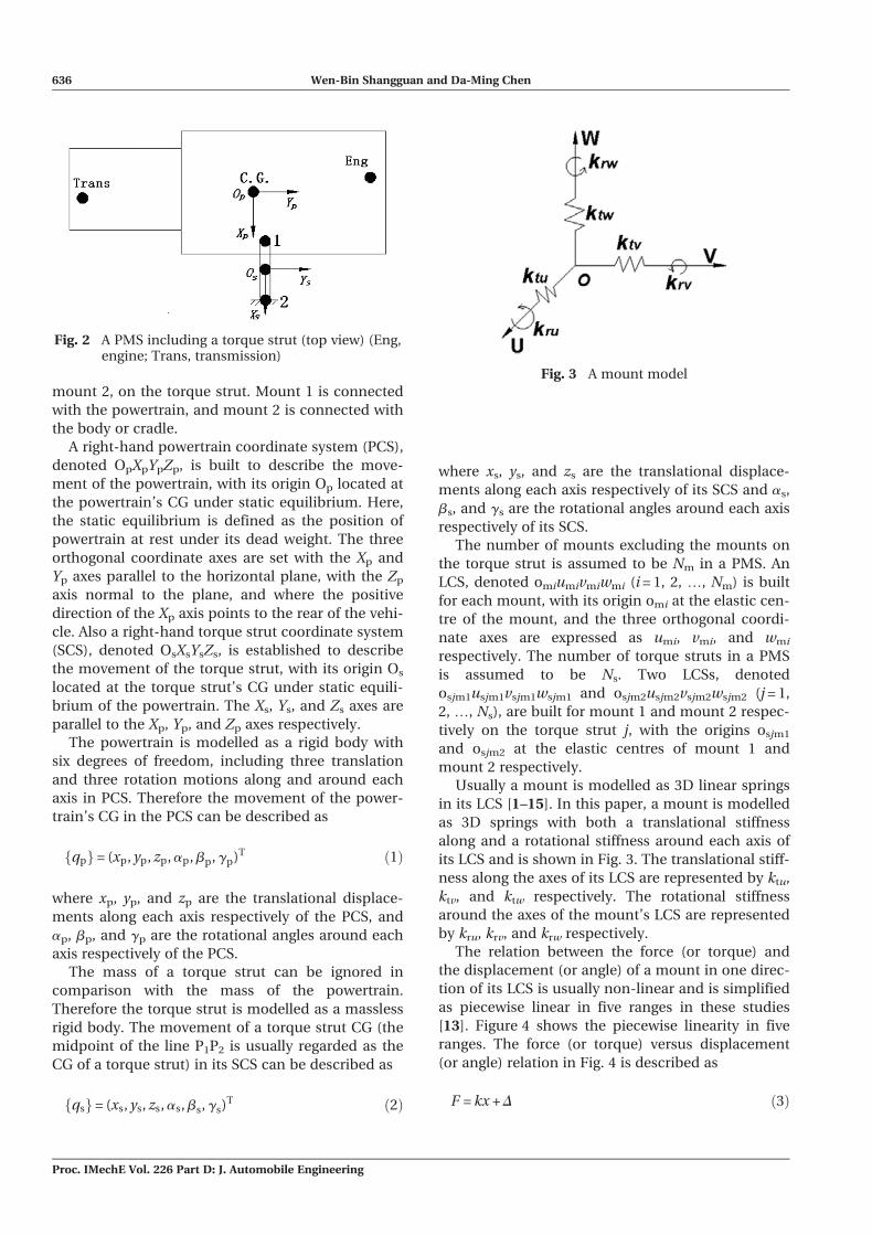
The relation between the force (or torque) and
the displacement (or angle) of a mount in one direc-
tion of its LCS is usually non-linear and is simplified
as piecewise linear in five ranges in these studies
[13]. Figure 4 shows the piecewise linearity in five
ranges. The force (or torque) versus displacement
(or angle) relation in Fig. 4 is described as
F = kx + D ð3Þ
Fig. 3 A mount model
Fig. 2 A PMS including a torque strut (top view) (Eng,engine; Trans, transmission)
636 Wen-Bin Shangguan and Da-Ming Chen
Proc. IMechE Vol. 226 Part D: J. Automobile Engineering
where k and D are the stiffness (translational or
rotational) and the correction term respectively, and
their values can be obtained using the formulae in
Table 1 when the displacement x is determined.
3 EQUATIONS OF THE POWERTRAIN–TORQUE
STRUT SYSTEM
3.1 Equation of the powertrain
The quasi-static load including the force and the
torque applied to the powertrain’s CG in the PCS is
assumed to be {F}, and it is a (6 3 1) vector. The dis-
placements of a powertrain’s CG and of the CG of
torque strut j under the load {F} are {qp} and {qsj}
respectively. If the displacements of the power-
train’s CG is {qp} in the PCS, then the displacements
of mount i in PCS are calculated from [13, 14]
Upmi
� �f
pmi
� �8<:
9=;=
I, ~Rpmi
T
0, I
24
35fqpg ð4Þ
where the superscript p denotes that the values are
defined in the PCS, T denotes the transpose of a
matrix, Upmi
� �and f
pmi
� �are the translational dis-
placements and the rotational angles respectively of
mount i in the PCS, I is a (3 3 3) unity matrix, and 0
is a (3 3 3) zero matrix.~Rp
mi in equation (4) is a (3 3 3) skew-symmetric
matrix of the position vector Rpmi for mount i in the
PCS, i.e. if Rpmi is given by
Rpmi = x
pmii + y
pmi j + z
pmik ð5Þ
Then the skew-symmetric matrix ~Rpmi is expressed
as [13]
~Rpmi =
0 �zpmi y
pmi
zpmi 0 �x
pmi
�ypmi x
pmi 0
266664
377775 ð6Þ
where xpmi, y
pmi, and z
pmi are the coordinates of mount
i in the PCS.
The displacements of mount i in its LCS are then
obtained using
�Umi
� ��fmi
� �� �=
Ami½ �, 00, Ami½ �
� �I, ~Rp
mi
T
0, I
� �fqpg ð7Þ
where �Umi
� �and �fmi
� �are the translational displa-
cements of mount i along each axis and the rota-
tional angles of mount i around each axis
respectively of its LCS, and [Ami] is a (3 3 3) transfor-
mation matrix from the PCS to the LCS of mount i.
The transformation matrix can be easily formed
from the orientation of a mount with respect to the
PCS, which can be defined using Euler angles, direc-
tion cosines, etc. [14].
The forces applied to mount i in the PCS due to
the movement of the powertrain are
Fpmi
� �M
pmi
� �8<:
9=;=
Kpmit
� , 0
0, Kpmir
� 24
35 I, ~R
pmi
T
0, I
24
35fqpg
+Ami½ �T, 0
0, Ami½ �T
24
35fDmig ð8Þ
where Fpmi
� �and M
pmi
� �are the force vector (3 3 1)
and the torque vector (3 3 1) respectively applied to
mount i in the PCS, where
½K pmit�= ½Ami�T½Kmit�½Ami� ð9Þ
and
½K pmir�= ½Ami�T½Kmir�½Ami� ð10Þ
Fig. 4 Force versus displacement relation of a mountin one direction of its LCS
Table 1 Values for k and D
x range k D
Range 1 ( –N, a] k1 – k1a + k2(a – b) + k3bRange 2 (a, b] k2 –k2b + k3bRange 3 (b, c] k3 0Range 4 (c, d] k4 k3c – k4cRange 5 (d, + N) k5 k3c – k4c + k4d – k5d
A method for calculating the displacements of a powertrain and mounts in a powertrain mounting system 637
Proc. IMechE Vol. 226 Part D: J. Automobile Engineering

are the translational stiffness matrix and rotational
stiffness matrix respectively of mount i in the PCS,
and where [Kmit] = diag(kmitu, kmitv, kmitw) and
[Kmir] = diag(kmiru, kmirv, kmirw) are the translational
stiffness matrix and rotational stiffness matrix
respectively of mount i in its LCS.
fDmig in equation (8) is the correction vector of
mount i in its LCS and is expressed as
fDmig= (Dmitu, Dmitv, Dmitw, Dmiru, Dmirv, Dmirw)T
ð11Þ
where the value of each component in fDmig for
mount i is a correction term for different force ver-
sus displacement relations along or around its LCS.
The values of the components in [Kmit], [Kmir], and
fDmig can be obtained with the formulae in Table 1
according to the values of the components in �Umi
� �and �fmi
� �.
The powertrain is moved under the forces and
moments applied to the powertrain’s CG, and so the
location of mount i with respect to the PCS is chan-
ged. The new position vector R�pmi of mount i in the
PCS is estimated using
R�pmi = R
pmi + ½I, ~RpT
mi�fqpg ð12Þ
However, the mount location has usually been
regarded as fixed in previous studies [13, 14]. This
will cause calculation errors of the displacements if
the motion of a powertrain is large.
According to equation (8), the reaction forces and
moments of mount i applied to the powertrain in
the PCS in terms of the displacements of the power-
train’s CG are
RFpmi
� �RM
pmi
� �( )
=I, 0
~R�pmi, I
� � � Fpmi
� �� M
pmi
� �( )
=� K
pmit
� , K
pmit
� ~R
pmi
� ~R�pmi Kpmit
� , ~R�pmi K
pmit
� ~Rp
mi � Kpmir
� " #
qp
� ��
Ami½ �T, 0
~R�pmi Ami½ �T, Ami½ �T
" #fDmig
ð13Þ
The displacements of mount 1 on torque strut j
in the PCS are
Upsjm1
n of
psjm1
n o8><>:
9>=>;=
I, ~Rpsjm1
T
0, I
" #fqpg �
I, ~Rssjm1
T
0, I
" #fqsjg
ð14Þ
where Upsjm1
n oand f
psjm1
n oare the translational
displacements of mount 1 along each axis and the
rotational angles of mount 1 around each axis
respectively of the PCS. The superscript s denotes
that the values are defined in the SCS; ~Rssjm1 is a
(333) skew-symmetric matrix of the position vector
Rssjm1 for mount 1 in the SCS.
The displacements of mount 1 in its LCS are then
written as
�U sjm1
� �fsjm1
n o8<:
9=;=
Asjm1
� , 0
0, Asjm1
� " #
I, ~Rpsjm1
T
0, I
" #fqpg
�Asjm1
� , 0
0, Asjm1
� " #
I; ~Rssjm1
T
0, I
" #fqsjg
ð15Þ
where �U sjm1
� �and �fsjm1
n oare the translational dis-
placements and rotational angles respectively of
mount 1 in its LCS, and [Asjm1] is the transformation
matrix from the PCS to the LCS of mount 1.
The forces applied to mount 1 owing to the
movement of the powertrain and the torque strut j
in the PCS are
Fpsjm1
n oM
psjm1
n o8><>:
9>=>;=
Kpsjm1t
h i, 0
0, Kpsjm1r
h i264
375 I, ~Rp
sjm1
T
0, I
" #fqpg
�K
psjm1t
h i, 0
0, Kpsjm1r
h i264
375 I, ~Rs
sjm1T
0, I
" #fqsjg
+Asjm1
� T, 0
0, Asjm1
� T
" #fDsjm1g
ð16Þ
where Fpsjm1
n oand M
psjm1
n oare the force vector
(3 3 1) and torque vector (3 3 1) respectively of
mount 1, and fDsjm1g is the correction vector of
mount 1 in its LCS. The expression for the transla-
tional stiffness matrix ½K psjm1t� of mount 1 and the
rotational stiffness matrix ½K psjm1r� of mount 1 in the
PCS are
½K psjm1t�= ½Asjm1�T½Ksjm1t�½Asjm1� ð17Þ
and
½K psjm1r�= ½Asjm1�T½Ksjm1r�½Asjm1� ð18Þ
respectively where [Ksjm1t] = diag(ksjm1tu, ksjm1tv,
ksjm1tw) and [Ksjm1r] = diag(ksjm1ru, ksjm1rv, ksjm1rw)
are the translational stiffness matrix and
638 Wen-Bin Shangguan and Da-Ming Chen
Proc. IMechE Vol. 226 Part D: J. Automobile Engineering

rotational stiffness matrix respectively of mount 1 in
its LCS.
The values of the components in [Ksjm1t], [Ksjm1r],
and fDsjm1g can be obtained using the formulae in
Table 1 according to the values of the components
in �Usjm1
� �and �fsjm1
n o.
The powertrain is moved under the action of {F},
and so the location of mount 1 on torque strut j is
also changed. The new position vector R�psjm1 of
mount 1 in the PCS is calculated from
R�psjm1 = R
psjm1 + ½I, ~Rp
sjm1
T�fqpg ð19Þ
The reaction forces and moments of mount 1 to
the powertrain in the PCS are
RFpsjm1
n oRM
psjm1
n o8><>:
9>=>;=
I, 0~R�psjm1, I
" # � Fpsjm1
n o� M
psjm1
n o8><>:
9>=>;
=� K
psjm1t
h i, K
psjm1t
h i~Rp
sjm1
� ~R�psjm1 Kpsjm1t
h i, ~R�psjm1 K
psjm1t
h i~Rp
sjm1 � Kpsjm1r
h i264
375 qp
� �
�� K p
sjm1t
h i, K p
sjm1t
h i~Rs
sjm1
� ~R�psjm1 Kpsjm1t
h i, ~R�psjm1 K
psjm1t
h i~Rs
sjm1 � Kpsjm1r
h i264
375 qsj
� �
�Asjm1
� T, 0
~R�psjm1 Asjm1
� T, Asjm1
� T
24
35fDsjm1g
ð20Þ
Since the reaction forces and moments applied to
the powertrain from the mounts connected with the
powertrain, and the external load {F} applied to the
powertrain are in equilibrium status, the static equi-
librium equation of the powertrain can be obtained
and is expressed as
PNm
i = 1
RFpmi
� �PNm
i = 1
RMpmi
� �8>>><>>>:
9>>>=>>>;
+
PNs
j = 1
RFpsjm1
n oPNs
j = 1
RMpsjm1
n o8>>><>>>:
9>>>=>>>;
+ fFg= f0g
ð21Þ
3.2 Equation for the torque strut
Since each axis in the SCS of torque strut j is parallel
to the corresponding axis of the PCS, and according
to equation (16), the forces F ssjm1
n o, Ms
sjm1
n on oT
applied to mount 1 in the SCS of torque strut j are
expressed as
F ssjm1
n oM s
sjm1
n o8<:
9=;= �
Fpsjm1
n oM
psjm1
n o8<:
9=; ð22Þ
where the superscript s denotes that the values are
defined in the SCS.
When the displacements of torque strut j CG in
its SCS are fqsjg, the new position vector R�ssjm1 of
mount 1 on torque strut j in the SCS is
R�ssjm1 = Rssjm1 + ½I, ~Rs
sjm1T�fqsjg ð23Þ
The reaction forces and moments of mount 1
applied to torque strut j in the SCS are
RF ssjm1
n oRM s
sjm1
n o8><>:
9>=>;=
I, 0~R�ssjm1, I
" # � F ssjm1
n o� M s
sjm1
n o8><>:
9>=>;
=� K
psjm1t
h i, K
psjm1t
h i~Rs
sjm1
� ~R�ssjm1 Kpsjm1t
h i, ~R�ssjm1 K
psjm1t
h i~Rs
sjm1 � Kpsjm1r
h i264
375 qsj
� �
�� K
psjm1t
h i, K
psjm1t
h i~Rp
sjm1
� ~R�ssjm1 K psjm1t
h i, ~R�ssjm1 K p
sjm1t
h i~Rp
sjm1 � K psjm1r
h i264
375 qp
� �
+Asjm1
� T, 0
~R�ssjm1 Asjm1
� T, Asjm1
� T
24
35fDsjm1g
ð24Þ
Following the same procedures described above
to obtain the reaction forces and moments of mount
1 to torque strut j, the reaction forces and moments
of mount 2 to torque strut j in the SCS are
RF ssjm2
n oRM s
sjm2
n o8><>:
9>=>;=
� K ssjm2t
h i, K s
sjm2t
h i~Rs
sjm2
� ~R�ssjm2 K ssjm2t
h i, ~R�ssjm2 K s
sjm2t
h i~Rs
sjm2 � K ssjm2r
h i24
35 qsj
� �
� Asjm2
� T, 0
~R�ssjm2 Asjm2
� T, Asjm2
� T
" #fDsjm2g ð25Þ
where
½K ssjm2t�= ½Asjm2�T½Ksjm2t�½Asjm2� ð26Þ
and
½K ssjm2r�= ½Asjm2�T½Ksjm2r�½Asjm2� ð27Þ
A method for calculating the displacements of a powertrain and mounts in a powertrain mounting system 639
Proc. IMechE Vol. 226 Part D: J. Automobile Engineering
are the translational stiffness matrix and rotational
stiffness matrix respectively of mount 2 in the SCS
of torque strut j, [Asjm2] is the transformation matrix
from the SCS of torque strut j to the LCS of mount
2, [Ksjm2t] and [Ksjm2r] are the translational stiffness
matrix and rotational stiffness matrix respectively of
mount 2 in its LCS and they are diagonal matrices,
Rssjm2 is the initial position vector of mount 2 in the
SCS of torque strut j, R�ssjm2 is the new position vector
of mount 2 in the SCS of torque strut j if the torque
strut is moved owing to the movement of power-
train, and fDsjm2g is the correction vector of mount
2 in its LCS.
Since torque strut j is assumed to be a rigid body
without mass, and it is in equilibrium under the
reaction forces and moments of the two mounts at
its two ends, thus the equation for torque strut j in
its SCS is then written as
RF ssjm1
n oRM s
sjm1
n o8<:
9=;+
RF ssjm2
n oRM s
sjm2
n o8<:
9=;= 0f g ð28Þ
3.3 Equation of the powertrain–torque strut
system
By combining the equilibrium equations for the
powertrain, i.e. equation (21), and for torque strut j,
i.e. equation (28), the equilibrium equation of the
powertrain–torque strut system is then expressed as
PNm
i = 1
RFpmi
� �PNm
i = 1
RMpmi
� �8>>><>>>:
9>>>=>>>;
+
PNs
j = 1
RFpsjm1
n oPNs
j = 1
RMpsjm1
n o8>>><>>>:
9>>>=>>>;
+ fFg
RF ssjm1
n oRM s
sjm1
n o8<:
9=; +
RF ssjm2
n oRM s
sjm2
n o8<:
9=;
8<:
9=;
8>>>>>>>>>><>>>>>>>>>>:
9>>>>>>>>>>=>>>>>>>>>>;
= 0f g
ð29Þ
3.4 Solution of equations
Equation (29) is non-linear and a discrete Newton
iterative algorithm is used to solve it. The variables
in equation (29) are the displacement {qp} of the CG
for the powertrain and the displacement {qsj} of tor-
que strut j. For a non-linear equation, F(X) = 0,
where X are unknown variables, the discrete
Newton iterative algorithm is used to estimate its
solution. The relation for unknown variables in the
(m + 1)th iteration and mth iteration is
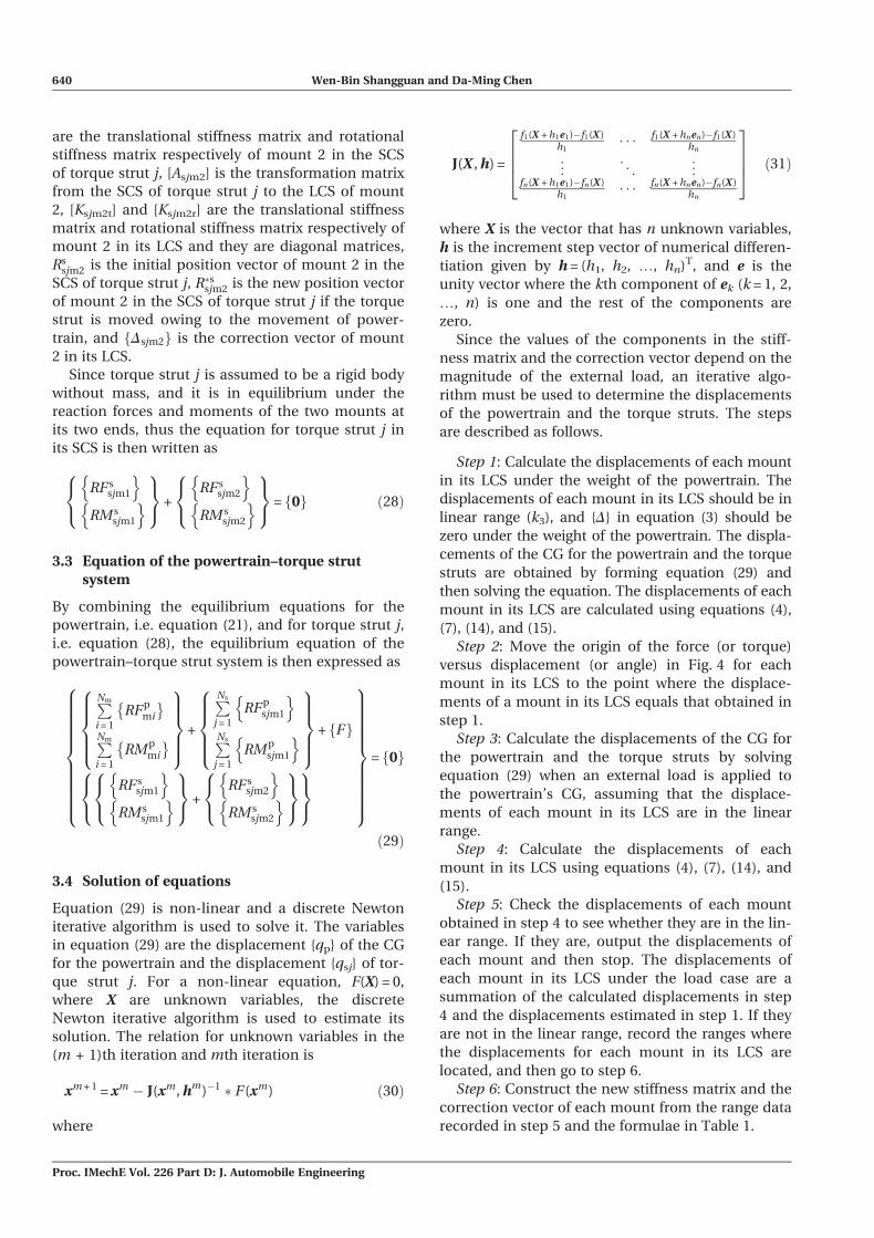
xm + 1 = xm � J(xm, hm)�1 � F(xm) ð30Þ
where
J(X , h) =
f1(X + h1e1)�f1(X )h1
� � � f1(X + hnen)�f1(X )hn
..
. . .. ..
.
fn(X + h1e1)�fn(X )h1
� � � fn(X + hnen)�fn(X )hn
2664
3775 ð31Þ
where X is the vector that has n unknown variables,
h is the increment step vector of numerical differen-
tiation given by h = (h1, h2, ., hn)T, and e is the
unity vector where the kth component of ek (k = 1, 2,
., n) is one and the rest of the components are
zero.
Since the values of the components in the stiff-
ness matrix and the correction vector depend on the
magnitude of the external load, an iterative algo-
rithm must be used to determine the displacements
of the powertrain and the torque struts. The steps
are described as follows.
Step 1: Calculate the displacements of each mount
in its LCS under the weight of the powertrain. The
displacements of each mount in its LCS should be in
linear range (k3), and {D} in equation (3) should be
zero under the weight of the powertrain. The displa-
cements of the CG for the powertrain and the torque
struts are obtained by forming equation (29) and
then solving the equation. The displacements of each
mount in its LCS are calculated using equations (4),
(7), (14), and (15).
Step 2: Move the origin of the force (or torque)
versus displacement (or angle) in Fig. 4 for each
mount in its LCS to the point where the displace-
ments of a mount in its LCS equals that obtained in
step 1.
Step 3: Calculate the displacements of the CG for
the powertrain and the torque struts by solving
equation (29) when an external load is applied to
the powertrain’s CG, assuming that the displace-
ments of each mount in its LCS are in the linear
range.
Step 4: Calculate the displacements of each
mount in its LCS using equations (4), (7), (14), and
(15).
Step 5: Check the displacements of each mount
obtained in step 4 to see whether they are in the lin-
ear range. If they are, output the displacements of
each mount and then stop. The displacements of
each mount in its LCS under the load case are a
summation of the calculated displacements in step
4 and the displacements estimated in step 1. If they
are not in the linear range, record the ranges where
the displacements for each mount in its LCS are
located, and then go to step 6.
Step 6: Construct the new stiffness matrix and the
correction vector of each mount from the range data
recorded in step 5 and the formulae in Table 1.
640 Wen-Bin Shangguan and Da-Ming Chen
Proc. IMechE Vol. 226 Part D: J. Automobile Engineering

Step 7: Estimate the displacements of the CG for
the powertrain and the torque struts by solving the
re-formed equation (29). Obtain the displacements
of each mount in its LCS using equations (4), (7),
(14), and (15).
Step 8: Check the displacements of each mount in
its LCS obtained in step 7 to see which ranges of the
displacements are located, and record the ranges of
the displacements for each mount in its LCS. If the
ranges are the same as in step 5, output the calcu-
lated results and then stop; otherwise, go to step 6.
In some loads, the iteration procedures stated above
may not converge owing to the inappropriate values
of the stiffness and tuning points. Therefore, an
interrupt program should be included in the pro-
gram designed.
4 APPLICATION EXAMPLES
4.1 Parameters of a powertrain mounting system
A generic PMS consisting of two mounts and a tor-
que strut is shown in Fig. 2. The powertrain has a
mass of 66.48 kg. The location of the powertrain’s
CG in the vehicle coordinate system (VCS) is
(1203.96, 31.09, 373.2) mm. The locations of each
mount in the VCS are listed in Table 2. Direction
angles are used to represent the orientation of a
mount in its LCS with respect to the PCS and are
listed in Table 3. The static stiffness (translational
and rotational) and the coordinates of tuning points
for each mount in three directions of its LCS are
listed in Tables 4 and 5 respectively. It is seen that
the translational and rotational stiffness of mount 1
on the torque strut are much larger than those of
the other mounts.
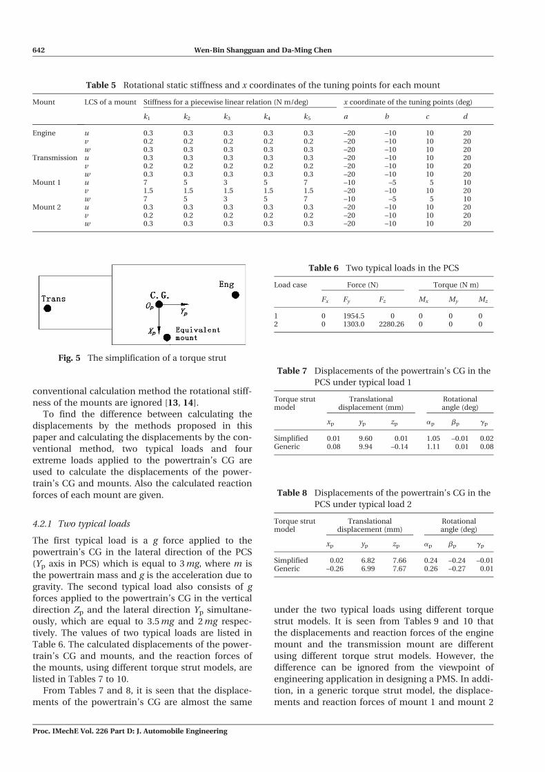
4.2 Calculation results
In the conventional calculation method, the torque
strut is simplified as a mount located at the position
of mount 1, as shown in Fig. 5. The translational
stiffness of the equivalent mount in the u direction
(line P1P2 in Fig. 1) is obtained by adding the trans-
lational stiffness of mount 1 and mount 2 in the u
direction using the principle of adding the stiffness
of two springs arranged in a series. The translational
stiffness of the simplified mount in the v and w
directions of its LCS are very small compared with
those in the u direction, and they are usually less
than 15 N/mm from experimental data. In the
Table 4 Translational static stiffness and x coordinates of the tuning points for each mount
Mount LCS of a mount Stiffness for a piecewise linear relation (N/mm) x coordinate of the tuning points (mm)
k1 k2 k3 k4 k5 a b c d
Engine u 500 250 70 250 500 –8 –3 3 8v 15 15 15 15 15 –6 –3 3 6w 800 300 60 300 800 –14 –9 2 5
Transmission u 800 250 60 250 800 –6 –3 3 6v 800 250 60 250 800 –6 –3 3 6w 800 300 85 300 800 –12 –9 0 2
Mount 1 u 8000 3000 1500 3000 8000 –3.5 –2 2 3.5v 250 250 250 250 250 –6 –4 4 6w 8000 3000 1500 3000 8000 –3.5 –2 2 3.5
Mount 2 u 800 500 90 500 800 –13 –4 3 13v 500 300 120 300 500 –13 –4 4 13w 500 40 40 40 500 –8 –6 6 8
Table 3 Mount orientations
Mount LCS of a mount Orientations in the PCS (deg)
X Y Z
Engine u 0 90 90v 90 0 90w 90 90 0
Transmission u 0 90 90v 90 0 90w 90 90 0
Mount 1 u 0 90 90v 90 0 90w 90 90 0
Mount 2 u 0 90 90v 90 0 90w 90 90 0
Table 2 Mount locations
Mount Coordinates in the VCS (mm)
X Y Z
Engine 1179.3 374.5 529.3Transmission 1178.5 –206.5 520.6Mount 1 1403.5 –0.9 165.7Mount 2 1570.5 –0.9 183.2
A method for calculating the displacements of a powertrain and mounts in a powertrain mounting system 641
Proc. IMechE Vol. 226 Part D: J. Automobile Engineering
conventional calculation method the rotational stiff-
ness of the mounts are ignored [13, 14].
To find the difference between calculating the
displacements by the methods proposed in this
paper and calculating the displacements by the con-
ventional method, two typical loads and four
extreme loads applied to the powertrain’s CG are
used to calculate the displacements of the power-
train’s CG and mounts. Also the calculated reaction
forces of each mount are given.
4.2.1 Two typical loads
The first typical load is a g force applied to the
powertrain’s CG in the lateral direction of the PCS
(Yp axis in PCS) which is equal to 3 mg, where m is
the powertrain mass and g is the acceleration due to
gravity. The second typical load also consists of g
forces applied to the powertrain’s CG in the vertical
direction Zp and the lateral direction Yp simultane-
ously, which are equal to 3.5 mg and 2 mg respec-
tively. The values of two typical loads are listed in
Table 6. The calculated displacements of the power-
train’s CG and mounts, and the reaction forces of
the mounts, using different torque strut models, are
listed in Tables 7 to 10.
From Tables 7 and 8, it is seen that the displace-
ments of the powertrain’s CG are almost the same
under the two typical loads using different torque
strut models. It is seen from Tables 9 and 10 that
the displacements and reaction forces of the engine
mount and the transmission mount are different
using different torque strut models. However, the
difference can be ignored from the viewpoint of
engineering application in designing a PMS. In addi-
tion, in a generic torque strut model, the displace-
ments and reaction forces of mount 1 and mount 2
Table 5 Rotational static stiffness and x coordinates of the tuning points for each mount
Mount LCS of a mount Stiffness for a piecewise linear relation (N m/deg) x coordinate of the tuning points (deg)
k1 k2 k3 k4 k5 a b c d
Engine u 0.3 0.3 0.3 0.3 0.3 –20 –10 10 20v 0.2 0.2 0.2 0.2 0.2 –20 –10 10 20w 0.3 0.3 0.3 0.3 0.3 –20 –10 10 20
Transmission u 0.3 0.3 0.3 0.3 0.3 –20 –10 10 20v 0.2 0.2 0.2 0.2 0.2 –20 –10 10 20w 0.3 0.3 0.3 0.3 0.3 –20 –10 10 20
Mount 1 u 7 5 3 5 7 –10 –5 5 10v 1.5 1.5 1.5 1.5 1.5 –20 –10 10 20w 7 5 3 5 7 –10 –5 5 10
Mount 2 u 0.3 0.3 0.3 0.3 0.3 –20 –10 10 20v 0.2 0.2 0.2 0.2 0.2 –20 –10 10 20w 0.3 0.3 0.3 0.3 0.3 –20 –10 10 20
Fig. 5 The simplification of a torque strut
Table 7 Displacements of the powertrain’s CG in the
PCS under typical load 1
Torque strutmodel
Translationaldisplacement (mm)
Rotationalangle (deg)
xp yp zp ap bp gp
Simplified 0.01 9.60 0.01 1.05 –0.01 0.02Generic 0.08 9.94 –0.14 1.11 0.01 0.08
Table 8 Displacements of the powertrain’s CG in the
PCS under typical load 2
Torque strutmodel
Translationaldisplacement (mm)
Rotationalangle (deg)
xp yp zp ap bp gp
Simplified 0.02 6.82 7.66 0.24 –0.24 –0.01Generic –0.26 6.99 7.67 0.26 –0.27 0.01
Table 6 Two typical loads in the PCS
Load case Force (N) Torque (N m)
Fx Fy Fz Mx My Mz
1 0 1954.5 0 0 0 02 0 1303.0 2280.26 0 0 0
642 Wen-Bin Shangguan and Da-Ming Chen
Proc. IMechE Vol. 226 Part D: J. Automobile Engineering

can be calculated simultaneously whereas, in the
conventional calculation method, a result is pro-
vided only for the simplified mount and cannot be
used directly in designing a torque strut.
From Tables 9 and 10, it is concluded that the
powertrain is in equilibrium under the external load
and the reaction forces of the engine mount, the
transmission mount, and mount 1. It is also shown
that the powertrain–torque strut system is in equili-
brium under the external load and the reaction
forces of the engine mount, the transmission
mount, and mount 2 on the torque strut. The equili-
brium for the powertrain and powertrain–torque
strut system validates the developed equations and
calculation method of obtaining the displacements
and reaction forces presented in this paper.
4.2.2 Extreme load cases
The first extreme load is a g force applied to the
powertrain’s CG in the lateral direction Yp of the
PCS and is equal to 5 mg. The second extreme load
is a g force applied to the powertrain’s CG in the
vertical direction Zp of the PCS and is equal to 5 mg.
The third extreme load is a g force applied to the
powertrain’s CG in the longitudinal direction Xp of
the PCS and is equal to 11 mg; this load case is
called longitudinal impact. The fourth extreme load
is a maximum torque load applied around the
crankshaft of powertrain (the Yp axis of the PCS)
and is equal to 15 times the maximum engine tor-
que. The values of the four extreme loads applied to
the powertrain’s CG are listed in Table 11. The cal-
culated displacements of the powertrain’s CG and
mounts, and the reaction forces of the mounts, are
listed in Tables 12 to 16 using different torque strut
models.
It is seen from Table 12 that, when an extreme
load in a lateral or vertical direction is applied to the
powertrain, the displacements of the powertrain’s
CG are approximately equal using different torque
strut models and calculation methods. However,
when the powertrain is applied with a longitudinal
impact load or a large torque, the translational
movements of the powertrain’s CG in the Xp and Zp
directions obtained by the proposed method in this
paper are larger than those obtained by the conven-
tional method. Therefore it is concluded that, when
the powertrain is applied with a longitudinal impact
load or a large torque, the torque strut cannot be
simplified as one mount in order to obtain the
results with high calculation precision.
Table 9 Displacements and reaction forces of the mounts under typical load 1
Mount Torque strut model Displacement in the LCS (mm) Reaction force in the PCS (N)
u v w Fx Fy Fz
Engine Simplified 0.42 6.74 1.84 –29.6 –101.1 –110.5Generic –0.25 6.88 2.17 17.23 –103.10 –171.82
Transmission Simplified 1.24 6.90 –8.87 –74.7 –1651.4 753.70Generic 0.74 7.04 –9.13 –44.2 –1763.0 802.90
Torque strut Simplified –1.16 13.47 –0.55 104.3 –202.0 8.30Mount 1 –0.02 0.35 –0.01 26.99 –88.36 20.39Mount 2 –0.30 0.74 –0.51 26.99 –88.36 20.39
Table 10 Displacements and reaction forces of the mounts under typical load 2
Mount Torque strut model Displacement in the LCS (mm) Reaction force in the PCS (N)
u v w Fx Fy Fz
Engine Simplified –0.04 6.17 4.55 2.60 –92.60 –883.50Generic –0.93 6.25 4.78 64.88 –93.80 –955.36
Transmission Simplified 0.51 6.21 2.02 –30.70 –1095.70 –619.70Generic –0.62 6.29 2.07 36.9 –1164.8 –654.90
Torque strut Simplified –0.31 7.65 8.37 28.10 –114.70 –125.60Mount 1 0.07 0.18 0.01 –101.79 –44.45 –18.47Mount 2 1.13 0.37 0.46 –101.79 –44.45 –18.47
Table 11 Four extreme loads in the PCS
Load case Force (N) Torque (N m)
Fx Fy Fz Mx My Mz
Lateral load 0 3257.5 0 0 0 0Vertical load 0 0 3257.5 0 0 0Longitudinal impact load 7166.6 0 0 0 0 0Large torque 0 0 0 0 2009 0
A method for calculating the displacements of a powertrain and mounts in a powertrain mounting system 643
Proc. IMechE Vol. 226 Part D: J. Automobile Engineering
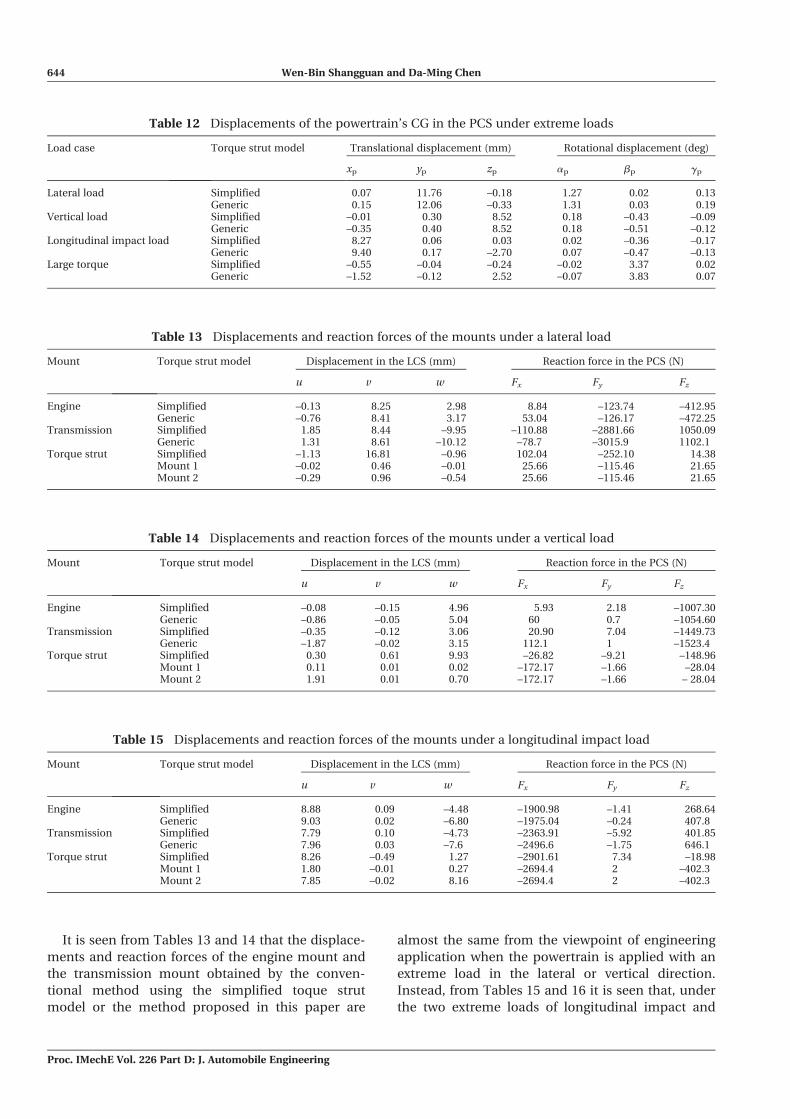
It is seen from Tables 13 and 14 that the displace-
ments and reaction forces of the engine mount and
the transmission mount obtained by the conven-
tional method using the simplified toque strut
model or the method proposed in this paper are
almost the same from the viewpoint of engineering
application when the powertrain is applied with an
extreme load in the lateral or vertical direction.
Instead, from Tables 15 and 16 it is seen that, under
the two extreme loads of longitudinal impact and
Table 12 Displacements of the powertrain’s CG in the PCS under extreme loads
Load case Torque strut model Translational displacement (mm) Rotational displacement (deg)
xp yp zp ap bp gp
Lateral load Simplified 0.07 11.76 –0.18 1.27 0.02 0.13Generic 0.15 12.06 –0.33 1.31 0.03 0.19
Vertical load Simplified –0.01 0.30 8.52 0.18 –0.43 –0.09Generic –0.35 0.40 8.52 0.18 –0.51 –0.12
Longitudinal impact load Simplified 8.27 0.06 0.03 0.02 –0.36 –0.17Generic 9.40 0.17 –2.70 0.07 –0.47 –0.13
Large torque Simplified –0.55 –0.04 –0.24 –0.02 3.37 0.02Generic –1.52 –0.12 2.52 –0.07 3.83 0.07
Table 13 Displacements and reaction forces of the mounts under a lateral load
Mount Torque strut model Displacement in the LCS (mm) Reaction force in the PCS (N)
u v w Fx Fy Fz
Engine Simplified –0.13 8.25 2.98 8.84 –123.74 –412.95Generic –0.76 8.41 3.17 53.04 –126.17 –472.25
Transmission Simplified 1.85 8.44 –9.95 –110.88 –2881.66 1050.09Generic 1.31 8.61 –10.12 –78.7 –3015.9 1102.1
Torque strut Simplified –1.13 16.81 –0.96 102.04 –252.10 14.38Mount 1 –0.02 0.46 –0.01 25.66 –115.46 21.65Mount 2 –0.29 0.96 –0.54 25.66 –115.46 21.65
Table 14 Displacements and reaction forces of the mounts under a vertical load
Mount Torque strut model Displacement in the LCS (mm) Reaction force in the PCS (N)
u v w Fx Fy Fz
Engine Simplified –0.08 –0.15 4.96 5.93 2.18 –1007.30Generic –0.86 –0.05 5.04 60 0.7 –1054.60
Transmission Simplified –0.35 –0.12 3.06 20.90 7.04 –1449.73Generic –1.87 –0.02 3.15 112.1 1 –1523.4
Torque strut Simplified 0.30 0.61 9.93 –26.82 –9.21 –148.96Mount 1 0.11 0.01 0.02 –172.17 –1.66 –28.04Mount 2 1.91 0.01 0.70 –172.17 –1.66 – 28.04
Table 15 Displacements and reaction forces of the mounts under a longitudinal impact load
Mount Torque strut model Displacement in the LCS (mm) Reaction force in the PCS (N)
u v w Fx Fy Fz
Engine Simplified 8.88 0.09 –4.48 –1900.98 –1.41 268.64Generic 9.03 0.02 –6.80 –1975.04 –0.24 407.8
Transmission Simplified 7.79 0.10 –4.73 –2363.91 –5.92 401.85Generic 7.96 0.03 –7.6 –2496.6 –1.75 646.1
Torque strut Simplified 8.26 –0.49 1.27 –2901.61 7.34 –18.98Mount 1 1.80 –0.01 0.27 –2694.4 2 –402.3Mount 2 7.85 –0.02 8.16 –2694.4 2 –402.3
644 Wen-Bin Shangguan and Da-Ming Chen
Proc. IMechE Vol. 226 Part D: J. Automobile Engineering
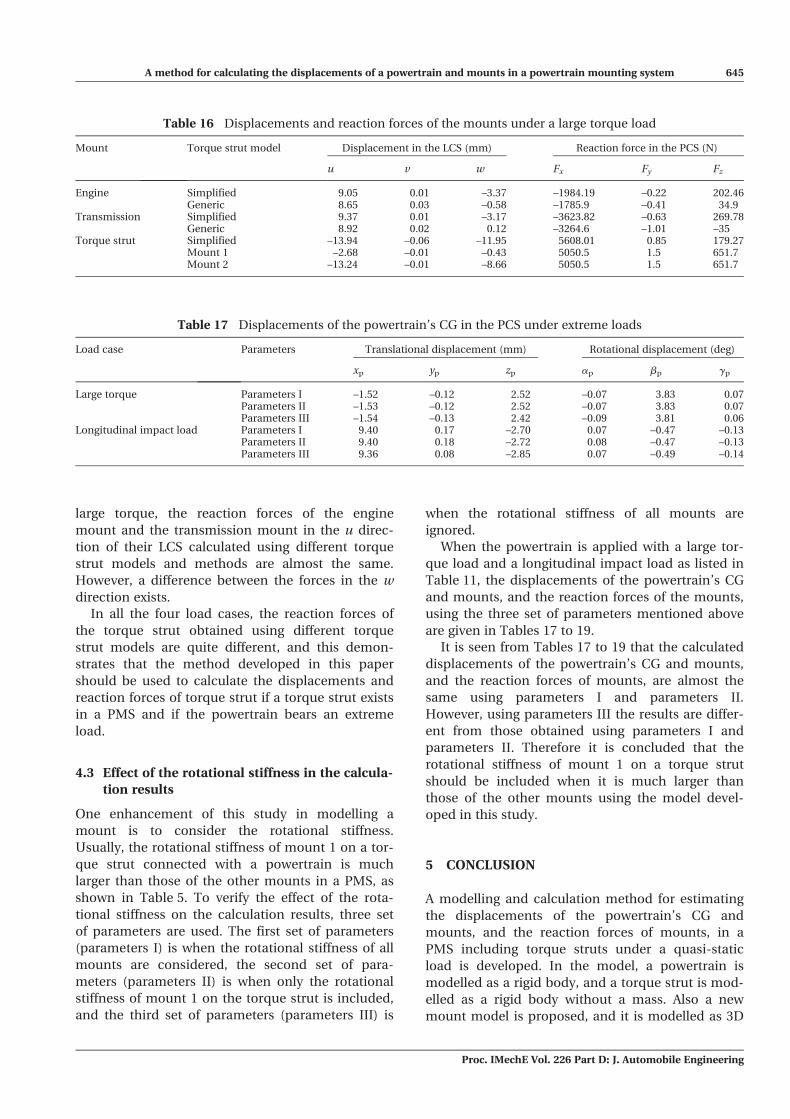
large torque, the reaction forces of the engine
mount and the transmission mount in the u direc-
tion of their LCS calculated using different torque
strut models and methods are almost the same.
However, a difference between the forces in the w
direction exists.
In all the four load cases, the reaction forces of
the torque strut obtained using different torque
strut models are quite different, and this demon-
strates that the method developed in this paper
should be used to calculate the displacements and
reaction forces of torque strut if a torque strut exists
in a PMS and if the powertrain bears an extreme
load.
4.3 Effect of the rotational stiffness in the calcula-
tion results
One enhancement of this study in modelling a
mount is to consider the rotational stiffness.
Usually, the rotational stiffness of mount 1 on a tor-
que strut connected with a powertrain is much
larger than those of the other mounts in a PMS, as
shown in Table 5. To verify the effect of the rota-
tional stiffness on the calculation results, three set
of parameters are used. The first set of parameters
(parameters I) is when the rotational stiffness of all
mounts are considered, the second set of para-
meters (parameters II) is when only the rotational
stiffness of mount 1 on the torque strut is included,
and the third set of parameters (parameters III) is
when the rotational stiffness of all mounts are
ignored.
When the powertrain is applied with a large tor-
que load and a longitudinal impact load as listed in
Table 11, the displacements of the powertrain’s CG
and mounts, and the reaction forces of the mounts,
using the three set of parameters mentioned above
are given in Tables 17 to 19.
It is seen from Tables 17 to 19 that the calculated
displacements of the powertrain’s CG and mounts,
and the reaction forces of mounts, are almost the
same using parameters I and parameters II.
However, using parameters III the results are differ-
ent from those obtained using parameters I and
parameters II. Therefore it is concluded that the
rotational stiffness of mount 1 on a torque strut
should be included when it is much larger than
those of the other mounts using the model devel-
oped in this study.
5 CONCLUSION
A modelling and calculation method for estimating
the displacements of the powertrain’s CG and
mounts, and the reaction forces of mounts, in a
PMS including torque struts under a quasi-static
load is developed. In the model, a powertrain is
modelled as a rigid body, and a torque strut is mod-
elled as a rigid body without a mass. Also a new
mount model is proposed, and it is modelled as 3D
Table 16 Displacements and reaction forces of the mounts under a large torque load
Mount Torque strut model Displacement in the LCS (mm) Reaction force in the PCS (N)
u v w Fx Fy Fz
Engine Simplified 9.05 0.01 –3.37 –1984.19 –0.22 202.46Generic 8.65 0.03 –0.58 –1785.9 –0.41 34.9
Transmission Simplified 9.37 0.01 –3.17 –3623.82 –0.63 269.78Generic 8.92 0.02 0.12 –3264.6 –1.01 –35
Torque strut Simplified –13.94 –0.06 –11.95 5608.01 0.85 179.27Mount 1 –2.68 –0.01 –0.43 5050.5 1.5 651.7Mount 2 –13.24 –0.01 –8.66 5050.5 1.5 651.7
Table 17 Displacements of the powertrain’s CG in the PCS under extreme loads
Load case Parameters Translational displacement (mm) Rotational displacement (deg)
xp yp zp ap bp gp
Large torque Parameters I –1.52 –0.12 2.52 –0.07 3.83 0.07Parameters II –1.53 –0.12 2.52 –0.07 3.83 0.07Parameters III –1.54 –0.13 2.42 –0.09 3.81 0.06
Longitudinal impact load Parameters I 9.40 0.17 –2.70 0.07 –0.47 –0.13Parameters II 9.40 0.18 –2.72 0.08 –0.47 –0.13Parameters III 9.36 0.08 –2.85 0.07 –0.49 –0.14
A method for calculating the displacements of a powertrain and mounts in a powertrain mounting system 645
Proc. IMechE Vol. 226 Part D: J. Automobile Engineering

springs with both a translational stiffness along each
axis and a rotational stiffness around each axis of its
LCS. The equation and the solution method for esti-
mating the displacements of the powertrain’s CG
and mounts under a quasi-static load is developed
when a torque strut exists in a PMS. An example is
given to calculate the displacements of the power-
train’s CG and mounts in a generic PMS including a
torque strut under some typical and extreme load
cases using the two different torque strut models.
From the calculations, the following conclusions are
found.
1. The calculated displacements of the power-
train’s CG are almost the same under typical
loads in the lateral and the vertical directions
using different torque strut models and calcula-
tion methods.
2. The displacements and the reaction forces of the
mounts excluded the mounts on the torque
struts obtained by different torque strut models,
and the calculation methods are different under
typical load cases. However, the difference can
be ignored from the viewpoint of engineering
application in designing a PMS.
3. When an extreme longitudinal impact load or a
large torque around the crankshaft is applied to
the powertrain, the translational displacements
of the powertrain’s CG calculated by the method
proposed in this paper are larger than those
obtained by the conventional method. Also the
estimated displacements and reaction forces of
mounts are different using different torque strut
models. Therefore it is concluded that, when the
powertrain is applied with an extreme longitudi-
nal impact load or a large torque, the torque
strut cannot be simplified as one mount.
4. The displacements and reaction forces of mount
1 and mount 2 on a torque strut can be calcu-
lated simultaneously when no simplification is
made to a torque strut. When in the conven-
tional calculation method a torque strut is sim-
plified as one mount, the displacements and
reaction forces are only provided for a simplified
mount, and the results cannot be used directly
in designing a torque strut.
Table 18 Displacements and reaction forces of the mounts under a large torque load
Mount Parameters Displacement in the LCS (mm) Reaction force in the PCS (N)
u v w Fx Fy Fz
Engine Parameters I 8.65 0.03 –0.58 –1785.9 –0.41 34.9Parameters II 8.66 0.03 –0.60 –1787.70 –0.46 35.82Parameters III 8.69 0.08 –0.87 –1803.84 –1.16 51.91
Transmission Parameters I 8.92 0.02 0.12 –3264.6 –1.01 –35Parameters II 8.92 0.02 0.11 –3268.44 –1.17 –33.34Parameters III 8.97 0.06 –0.02 –3305.74 –3.84 1.60
Mount 1 Parameters I –2.68 –0.01 –0.43 5050.5 1.5 651.7Parameters II –2.69 –0.01 –0.43 5056.14 1.62 649.03Parameters III –2.70 –0.02 –0.40 5109.58 4.99 598
Mount 2 Parameters I –13.24 –0.01 –8.66 5050.5 1.5 651.7Parameters II –13.25 –0.01 –8.66 5056.14 1.62 649.03Parameters III –13.31 –0.04 –8.56 5056.14 1.62 649.03
Table 19 Displacements and reaction forces of the mounts under a longitudinal impact load
Mount Rotational stiffness Displacement in the LCS (mm) Reaction forces in the PCS (N)
u v w Fx Fy Fz
Engine Parameters I 9.03 0.02 –6.80 –1975.04 –0.24 407.8Parameters II 9.03 0.02 –6.82 –1976.74 –0.25 409.40Parameters III 9.07 –0.05 –7.06 –1994.72 0.78 423.37
Transmission Parameters I 7.96 0.03 –7.6 –2496.6 –1.75 646.1Parameters II 7.96 0.03 –7.64 –2498.52 –1.84 649.54Parameters III 7.99 –0.04 –7.84 –2520.68 2.31 666.55
Mount 1 Parameters I 1.80 –0.01 0.27 –2694.4 2 –402.3Parameters II 1.79 –0.01 0.27 –2691.23 2.09 –407.44Parameters III 1.77 0.01 0.29 –2651.10 –3.09 –438.42
Mount 2 Parameters I 7.85 –0.02 8.16 –2694.4 2 –402.3Parameters II 7.84 –0.02 8.17 –2691.23 2.09 –407.44Parameters III 7.76 0.03 8.24 –2651.10 –3.09 –438.42
646 Wen-Bin Shangguan and Da-Ming Chen
Proc. IMechE Vol. 226 Part D: J. Automobile Engineering

5. When the rotational stiffness of mount 1 on the
torque strut is much larger than those of the
other mounts, only the rotational stiffness of
mount 1 needs to be considered in the
calculation.
FUNDING
This work was supported by the the NaturalScience Foundation of China [project nos50575073 and 50975091] and the Foundation ofNational Automobile Dynamic SimulationLaboratory in Jilin University [grant no. 2010-06].
� Authors 2011
REFERENCES
1 Yu, Y., Naganathan Nagi, G., and Dukkipati, R. V.A literature review of automotive vehicle enginemounting systems. Mechanism Mach. Theory, 2001,36(1), 123–142.
2 Johson, S. R. and Subhedar, J. W. Computer opti-mization of engine mounting systems. SAE paper790974, 1979.
3 Geck, P. E. and Patton, R. D. Front wheel driveengine mount optimization. SAE paper 840736,1984.
4 Shuangguan, W.-B. Engine mounts and powertrainmounting system: a review. Int. J. Veh. Des., 2009,49(4), 237–258.
5 Ishihama, M., Seto, K., Nagamatsu, A., and Doi, K.Control of engine roll and bounce vibration using
hydraulic mounts. JSME Int. J., Ser. C, 1995, 38(1),29–35.
6 Tao, J. S., Liu, G. R., and Lam, K. Y. Design optimi-zation of marine engine mount system. J. SoundVibr., 2000, 235(3), 477–494.
7 Bernard, J. E. and Starkey, J. M. Engine mountoptimization. SAE paper 830257, 1983.
8 Cho, S. Configuration and sizing optimization ofpowertrain mounting systems. Int. J. Veh. Des.,2000, 24(1), 34–37.
9 Demic, M. A contribution to the optimization ofthe position and the characteristics of a passengercar powertrain mounts. Int. J. Veh. Des., 1990,11(1), 87–99.
10 Sachdeva, D. S. and Hadi, R. Effect of enginemounting strategy on vehicle NVH. SAE paper2003-01-1467, 2003.
11 Brach, R. M. Automotive powerplant isolation stra-tegies. SAE paper 971942, 1997.
12 Diemer, P., Hueser, M. G., Govindswamy, K., andD’Anna, T. Aspects of powerplant integration withemphasis on mount and bracket optimization. SAEpaper 2003-01-1468, 2003.
13 Shangguan, W.-B. and Hou, Z. Strategies and cal-culation methods for automotive powertrainmotion control under quasi-static loads. Proc.IMechE, Part D: J. Automobile Engineering, 2006,220(8), 1131–1138.
14 Swanson, D. A., Wu, H. T., and Ashrafiuon, H.Optimization of aircraft engine suspension sys-tems. J. Aircr., 1993, 30(6), 979–984.
15 Sirafi, M. and Qatu, M. Accurate modeling forpowertrain and subframe models. SAE paper 2003-01-1469, 2003.
A method for calculating the displacements of a powertrain and mounts in a powertrain mounting system 647
Proc. IMechE Vol. 226 Part D: J. Automobile Engineering