
A Low-Order HCCI Model Extended to Capture SI-HCCI Mode ...
8
A LOW-ORDER HCCI MODEL EXTENDED TO CAPTURE SI-HCCI MODE TRANSITION DATA WITH TWO-STAGE CAM SWITCHING Patrick Gorzelic, Prasad Shingne, Jason Martz, and Anna Stefanopoulou University of Michigan Ann Arbor, Michigan, 48109 Email: [email protected] Jeff Sterniak and Li Jiang Robert Bosch LLC Farmington Hills, Michigan, 48331 ABSTRACT A low-order homogeneous charge compression ignition (HCCI) combustion model to support model-based control de- velopment for spark ignition (SI)/HCCI mode transitions is pre- sented. Emphasis is placed on mode transition strategies wherein SI combustion is abruptly switched to recompression HCCI com- bustion through a change of the cam lift and opening of the throttle, as is often employed in studies utilizing two-stage cam switching devices. The model is parameterized to a steady-state dataset which considers throttled operation and significant air- fuel ratio variation, which are pertinent conditions to two-stage cam switching mode transition strategies. Inspection and simu- lation of transient SI to HCCI (SI-HCCI) mode transition data shows that the extreme conditions present when switching from SI to HCCI can cause significant prediction error in the combus- tion performance outputs even with the model’s adequate steady- state fit. When a correction factor related to residual gas temper- ature is introduced to account for these extreme conditions, it is shown that the model reproduces transient performance output time histories in SI-HCCI mode transition data. The model is thus able to capture steady-state data as well as transient SI- HCCI mode transition data while maintaining a low-order cycle to cycle structure, making it tractable for model-based control of SI-HCCI mode transitions. INTRODUCTION Homogeneous charge compression ignition (HCCI) com- bustion offers significant improvements in fuel economy relative to traditional spark ignition (SI) gasoline combustion while pro- ducing low nitrogen oxide emissions [1]. An obstacle to attaining the benefits of HCCI is that its feasible operating range is limited to a low to mid speed-load region of the full regime of conven- tional engines. Outside this range, SI combustion must be re- verted to, which implies that transitions between SI and HCCI combustion must carried out. Most SI/HCCI mode transition studies approach the problem by means of open-loop calibra- tion of actuator sequences to change between the modes [2–11]. Other works have proposed model-based feedback control ap- proaches [12, 13] to the mode transition problem, which may help alleviate the calibration burden associated with scheduling open-loop sequences and also improve robustness to operating condition and environmental factors. A low-order, computationally efficient HCCI model is indis- pensable for model-based control approaches to SI/HCCI transi- tions, and may also be a useful tool for offline trajectory opti- mization in open-loop approaches. Numerous control-oriented HCCI models exist in the literature e.g. [14–19], though few are concerned with mode transitions. The models of [17, 18] utilize topologies wherein the model states evolve in the crank angle do- main, and must be numerically integrated throughout the cycle to calculate performance outputs such as torque and combustion phasing. The higher fidelity and physicality of these models is preferable to reduce the dependency on empirical parameteriza- tion, however the implicit and complex relationship between the inputs and performance outputs present in such model topologies makes development of model-based controllers difficult. In [13], a linearized feedforward controller was designed based on a pre- 1 Copyright © 2014 by ASME Proceedings of the ASME 2014 Dynamic Systems and Control Conference DSCC2014 October 22-24, 2014, San Antonio, TX, USA DSCC2014-6275 Downloaded From: http://proceedings.asmedigitalcollection.asme.org/ on 02/18/2016 Terms of Use: http://www.asme.org/about-asme/terms-of-use
-
Upload
khangminh22 -
Category
Documents
-
view
1 -
download
0
Transcript of A Low-Order HCCI Model Extended to Capture SI-HCCI Mode ...
A LOW-ORDER HCCI MODEL EXTENDED TO CAPTURE SI-HCCI MODETRANSITION DATA WITH TWO-STAGE CAM SWITCHING
Patrick Gorzelic, Prasad Shingne,Jason Martz, and Anna Stefanopoulou
University of MichiganAnn Arbor, Michigan, 48109
Email: [email protected]
Jeff Sterniak and Li JiangRobert Bosch LLC
Farmington Hills, Michigan, 48331
ABSTRACTA low-order homogeneous charge compression ignition
(HCCI) combustion model to support model-based control de-velopment for spark ignition (SI)/HCCI mode transitions is pre-sented. Emphasis is placed on mode transition strategies whereinSI combustion is abruptly switched to recompression HCCI com-bustion through a change of the cam lift and opening of thethrottle, as is often employed in studies utilizing two-stage camswitching devices. The model is parameterized to a steady-statedataset which considers throttled operation and significant air-fuel ratio variation, which are pertinent conditions to two-stagecam switching mode transition strategies. Inspection and simu-lation of transient SI to HCCI (SI-HCCI) mode transition datashows that the extreme conditions present when switching fromSI to HCCI can cause significant prediction error in the combus-tion performance outputs even with the model’s adequate steady-state fit. When a correction factor related to residual gas temper-ature is introduced to account for these extreme conditions, it isshown that the model reproduces transient performance outputtime histories in SI-HCCI mode transition data. The model isthus able to capture steady-state data as well as transient SI-HCCI mode transition data while maintaining a low-order cycleto cycle structure, making it tractable for model-based control ofSI-HCCI mode transitions.
INTRODUCTIONHomogeneous charge compression ignition (HCCI) com-
bustion offers significant improvements in fuel economy relative
to traditional spark ignition (SI) gasoline combustion while pro-ducing low nitrogen oxide emissions [1]. An obstacle to attainingthe benefits of HCCI is that its feasible operating range is limitedto a low to mid speed-load region of the full regime of conven-tional engines. Outside this range, SI combustion must be re-verted to, which implies that transitions between SI and HCCIcombustion must carried out. Most SI/HCCI mode transitionstudies approach the problem by means of open-loop calibra-tion of actuator sequences to change between the modes [2–11].Other works have proposed model-based feedback control ap-proaches [12, 13] to the mode transition problem, which mayhelp alleviate the calibration burden associated with schedulingopen-loop sequences and also improve robustness to operatingcondition and environmental factors.
A low-order, computationally efficient HCCI model is indis-pensable for model-based control approaches to SI/HCCI transi-tions, and may also be a useful tool for offline trajectory opti-mization in open-loop approaches. Numerous control-orientedHCCI models exist in the literature e.g. [14–19], though few areconcerned with mode transitions. The models of [17, 18] utilizetopologies wherein the model states evolve in the crank angle do-main, and must be numerically integrated throughout the cycleto calculate performance outputs such as torque and combustionphasing. The higher fidelity and physicality of these models ispreferable to reduce the dependency on empirical parameteriza-tion, however the implicit and complex relationship between theinputs and performance outputs present in such model topologiesmakes development of model-based controllers difficult. In [13],a linearized feedforward controller was designed based on a pre-
1 Copyright © 2014 by ASME
Proceedings of the ASME 2014 Dynamic Systems and Control Conference DSCC2014
October 22-24, 2014, San Antonio, TX, USA
DSCC2014-6275
Downloaded From: http://proceedings.asmedigitalcollection.asme.org/ on 02/18/2016 Terms of Use: http://www.asme.org/about-asme/terms-of-use
viously developed reduced order HCCI model [19], which wasshown to improve performance during SI-HCCI mode transi-tions. The mode transition strategy employed in [13] differs fromthe strategies considered by this paper in that the mode is grad-ually changed from SI to HCCI through continuous phasing ofthe cams, while the strategies considered in this paper abruptlychange the mode from SI to HCCI with a switch of the cam pro-file. The abrupt mode change results in a more drastic step in theoperating condition when switching from SI to HCCI, which themodel of this paper is modified to account for.
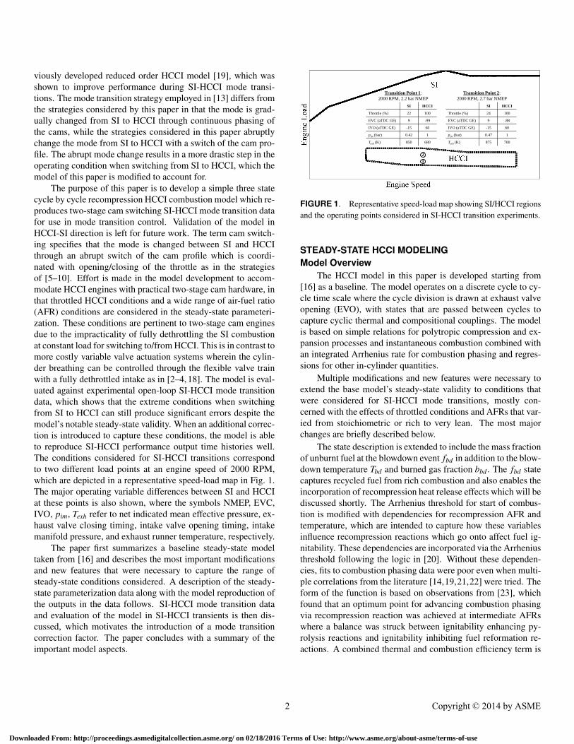
The purpose of this paper is to develop a simple three statecycle by cycle recompression HCCI combustion model which re-produces two-stage cam switching SI-HCCI mode transition datafor use in mode transition control. Validation of the model inHCCI-SI direction is left for future work. The term cam switch-ing specifies that the mode is changed between SI and HCCIthrough an abrupt switch of the cam profile which is coordi-nated with opening/closing of the throttle as in the strategiesof [5–10]. Effort is made in the model development to accom-modate HCCI engines with practical two-stage cam hardware, inthat throttled HCCI conditions and a wide range of air-fuel ratio(AFR) conditions are considered in the steady-state parameteri-zation. These conditions are pertinent to two-stage cam enginesdue to the impracticality of fully dethrottling the SI combustionat constant load for switching to/from HCCI. This is in contrast tomore costly variable valve actuation systems wherein the cylin-der breathing can be controlled through the flexible valve trainwith a fully dethrottled intake as in [2–4, 18]. The model is eval-uated against experimental open-loop SI-HCCI mode transitiondata, which shows that the extreme conditions when switchingfrom SI to HCCI can still produce significant errors despite themodel’s notable steady-state validity. When an additional correc-tion is introduced to capture these conditions, the model is ableto reproduce SI-HCCI performance output time histories well.The conditions considered for SI-HCCI transitions correspondto two different load points at an engine speed of 2000 RPM,which are depicted in a representative speed-load map in Fig. 1.The major operating variable differences between SI and HCCIat these points is also shown, where the symbols NMEP, EVC,IVO, pim, Texh refer to net indicated mean effective pressure, ex-haust valve closing timing, intake valve opening timing, intakemanifold pressure, and exhaust runner temperature, respectively.
The paper first summarizes a baseline steady-state modeltaken from [16] and describes the most important modificationsand new features that were necessary to capture the range ofsteady-state conditions considered. A description of the steady-state parameterization data along with the model reproduction ofthe outputs in the data follows. SI-HCCI mode transition dataand evaluation of the model in SI-HCCI transients is then dis-cussed, which motivates the introduction of a mode transitioncorrection factor. The paper concludes with a summary of theimportant model aspects.
Transition Point 1:
2000 RPM, 2.2 bar NMEP
SI HCCI
Throttle (%) 22 100
EVC (aTDC GE) 9 -99
IVO (aTDC GE) -15 60
pim (bar) 0.42 1
Texh (K) 850 680
Transition Point 2:
2000 RPM, 2.7 bar NMEP
1
2
SI HCCI
Throttle (%) 24 100
EVC (aTDC GE) 9 -88
IVO (aTDC GE) -15 60
pim (bar) 0.47 1
Texh (K) 875 700
FIGURE 1. Representative speed-load map showing SI/HCCI regionsand the operating points considered in SI-HCCI transition experiments.
STEADY-STATE HCCI MODELINGModel Overview
The HCCI model in this paper is developed starting from[16] as a baseline. The model operates on a discrete cycle to cy-cle time scale where the cycle division is drawn at exhaust valveopening (EVO), with states that are passed between cycles tocapture cyclic thermal and compositional couplings. The modelis based on simple relations for polytropic compression and ex-pansion processes and instantaneous combustion combined withan integrated Arrhenius rate for combustion phasing and regres-sions for other in-cylinder quantities.
Multiple modifications and new features were necessary toextend the base model’s steady-state validity to conditions thatwere considered for SI-HCCI mode transitions, mostly con-cerned with the effects of throttled conditions and AFRs that var-ied from stoichiometric or rich to very lean. The most majorchanges are briefly described below.
The state description is extended to include the mass fractionof unburnt fuel at the blowdown event fbd in addition to the blow-down temperature Tbd and burned gas fraction bbd . The fbd statecaptures recycled fuel from rich combustion and also enables theincorporation of recompression heat release effects which will bediscussed shortly. The Arrhenius threshold for start of combus-tion is modified with dependencies for recompression AFR andtemperature, which are intended to capture how these variablesinfluence recompression reactions which go onto affect fuel ig-nitability. These dependencies are incorporated via the Arrheniusthreshold following the logic in [20]. Without these dependen-cies, fits to combustion phasing data were poor even when multi-ple correlations from the literature [14,19,21,22] were tried. Theform of the function is based on observations from [23], whichfound that an optimum point for advancing combustion phasingvia recompression reaction was achieved at intermediate AFRswhere a balance was struck between ignitability enhancing py-rolysis reactions and ignitability inhibiting fuel reformation re-actions. A combined thermal and combustion efficiency term is
2 Copyright © 2014 by ASME
Downloaded From: http://proceedings.asmedigitalcollection.asme.org/ on 02/18/2016 Terms of Use: http://www.asme.org/about-asme/terms-of-use

introduced as a function of the in-cylinder relative AFR λc to ac-count for changes in work output as AFR is varied by adjustingthe temperature and hence pressure rise due to combustion. Theefficiency term represents mainly the effects of combustion effi-ciency as λc nears stoichiometry and more the effect of thermalefficiency as λc becomes significantly lean. In addition to thesechanges to expand the model’s validity, the cylinder breathingmodel was reformulated to include a regression for the residualmass mr as opposed to the residual gas fraction xr, which provedfavorable for extension to mode transition transients.
Recompression heat release (RCHR) of recycled unburntfuel from main combustion was apparent in SI-HCCI mode tran-sition data where cycles with late combustion phasing were fol-lowed by an enlarged recompression peak. The resulting cycle tocycle coupling that is explained in [24] is captured with a modelmodified after that in [25], which consists of a sigmoidal maincombustion efficiency to capture unburnt fuel at late combustionphasing, and an instantaneous combustion of the unburnt fuel ata fixed angle during recompression. The combustion efficiencyis parameterized as a function of the 50% burn angle θ50 whosesigmoidal roll-off varies with fuel mass m f to capture changes inthe late phasing limit with load. The instantaneous combustionof the unburnt fuel is simplified from that in [25] in that it is takento occur with 100% efficiency directly at EVC. The heat releasewas chosen to be at EVC because this conforms with the rest ofmodel structure and aids the model regression.
Several of the important steady-state model aspects are ex-emplified in the throttle sweep data shown in Fig. 2. All otherinputs are held constant and the data is plotted versus pim. Asthe throttle is closed (moving right to left), the θ50 at first ad-vances and then retards, which is interpreted to be a conse-quence of trade-offs between temperature and pressure effectson auto-ignition as well as chemical effects on recompression re-actions due to varying oxygen concentration during recompres-sion. Definitively characterizing the relative magnitudes of theseeffects on combustion is a difficult task for which work is stillongoing, however the model is able to reproduce the qualitativetrend as well as approximate the absolute values of θ50 with suf-ficient accuracy. The plot of gross indicated mean effective pres-sure (IMEP) illustrates the trend for which the combined thermaland combustion efficiency is incorporated. As can be seen, as thethrottle is closed and λ decreases, there is at first a mild reduc-tion in the work output from combustion, which becomes moresevere as stoichiometry is approached. Note that IMEP is shownas opposed to NMEP to exclude any effects of pumping work.
Steady-State Fitting ResultsThe test engine to which the model is parameterized is a four
cylinder, two liter displacement engine with a geometric com-pression ratio of 11.7:1. The model is parameterized to a singlecylinder of the four. The engine is equipped with a two-stage
0.88 0.9 0.92 0.94 0.96 0.98
5
6
7
8
θ 50 (
aTD
C)
DataModel
0.88 0.9 0.92 0.94 0.96 0.98
2.8
2.85
2.9
2.95
3
IME
P (
bar)
0.88 0.9 0.92 0.94 0.96 0.981
1.1
1.2
λ
pim
(bar)
FIGURE 2. Sweeps of throttle with all other inputs held fixed at 2000RPM. Model reproduction of data is shown.
cam system to switch between high/low lift cams for SI/HCCIoperation and intake and exhaust cam phasers to vary the valvetimings, similar to the configurations of [6–10]. The high lift andlow lift cams are offset from each other by a fixed crank angleamount, so that when the cams are switched, the valve timingschange instantaneously. This offset is characterized by the differ-ence in the IVO and EVC for the intake and exhaust cams whichare equal to 47◦ and −34◦, respectively.
The dataset to which the model is parameterized consists ofa 526 point grid of actuator sweeps at a single engine speed of2000 RPM with the outermost swept variable being fuel massm f , followed pim (adjusted via throttle) and then EVC timingθevc, and the innermost variable being injection timing θsoi. Sev-eral direct throttle and EVC sweeps were also carried out toclearly discern the trend in the outputs with respect to these vari-ables. Intake valve timing was held fixed with intake valve clos-ing (IVC) near BDC, as it was observed to have only a smalleffect on combustion in the vicinity of BDC. The grid of inputsand corresponding performance outputs of θ50, NMEP, and λ areshown in Fig. 3.
The model parameters were regressed using an iterative pa-rameterization routine to consider the model’s inherent internalfeedback, and the reproduction of the performance outputs isplotted against the data in Fig. 3. As can be seen, the model re-produces the performance outputs with good accuracy for a low-order model considering the wide range of actuator settings overwhich it is fit. A summary of the swept input and output rangeand mean and max absolute model errors is given in Table 1.
EXTENSION TO SI-HCCI MODE TRANSITIONSThis Section discusses results from an experimental open-
loop SI-HCCI mode transition and describes modifications to thebase model needed to accurately capture the mode transition.
3 Copyright © 2014 by ASME
Downloaded From: http://proceedings.asmedigitalcollection.asme.org/ on 02/18/2016 Terms of Use: http://www.asme.org/about-asme/terms-of-use

50 100 150 200 250 300 350 400 450 500300
350
θ soi (
bTD
C)
50 100 150 200 250 300 350 400 450 500
260
280
θ evc (
aTD
C)
50 100 150 200 250 300 350 400 450 500
0.9
0.95
1
p im (
bar)
50 100 150 200 250 300 350 400 450 500
8
10
mf (
mg)
50 100 150 200 250 300 350 400 450 500
0
5
10
θ 50 (
aTD
C)
DataModel
50 100 150 200 250 300 350 400 450 500
2
2.5
3
NM
EP
(ba
r)
50 100 150 200 250 300 350 400 450 500
1
1.5
λ
Data Point
FIGURE 3. Input grid and modeled vs. measured outputs for steady-state model parameterization data.
Min Max Mean Abs. Err. Max Err.
θsoi (bTDC) 300 390 - -
θevc (aTDC) 250 290 - -
pim (bar) 0.85 1 - -
m f (mg) 7.2 10.5 - -
θ50 (aTDC) -2 11 0.86◦ 5.16◦
NMEP (bar) 1.7 3 2.06% 12.2%
λ 0.92 1.5 2.81% 11.2%
TABLE 1. Swept range of inputs and outputs in HCCI model param-eterization data. Mean and max absolute error between model and mea-surement listed for outputs. θ50 error reported in CAD to avoid divisionby small numbers at θ50 near TDC.
Mode Transition OverviewThe format for the mode transition experiments was to take
the engine to a steady-state condition in SI mode which was ap-propriate for switching to HCCI, then to switch the intake andexhaust cams simultaneously. The cams switch while the valves
are closed during the final SI cycle. The SI switch point condi-tion was set with an advanced EVC and retarded IVO timing inorder to diminish cylinder breathing as throttle was opened in anattempt to maintain constant load while dethrottling. The throt-tle was commanded open roughly 20-30 milliseconds before thefirst low-lift cam breathing event. In the simulation results pre-sented along with the data, the HCCI model is initialized with es-timates of the model states taken from steady-state data at the SIswitch point. The mode transition discussed corresponds to tran-sition point 1 in Fig. 1 for which the initial conditions for the firstHCCI cycle are estimated to be [T 0
bd ,b0bd , f 0
bd ] = [960 K,0.893,0],where superscript 0 indicates a recycled state from the previouscycle. T 0
bd is estimated based on exhaust runner temperature andb0
bd and f 0bd are calculated using the AFR on the final SI cycle
which was commanded to λ = 1.18. The values of 0 for f 0bd and
0.893 for b0bd indicate that approximately 10.7% of the residual
charge consists of unburnt air with no unburnt fuel.The combustion response and corresponding input se-
quences for the SI-HCCI mode transition trial are shown inFig. 4, where SI -1 and HCCI 0 designate the final SI cycle andfirst HCCI cycle, respectively, following the notation in [18]. Theslight recompression peak in cycle SI -2 is the result of the earlyEVC and late IVO timing at the SI end point employed to assistin dethrottling the engine. The independent axis of the time-
4 Copyright © 2014 by ASME
Downloaded From: http://proceedings.asmedigitalcollection.asme.org/ on 02/18/2016 Terms of Use: http://www.asme.org/about-asme/terms-of-use
−2 −1 0 1 2 3 4 5 6 7−100
−85−70−55−40
θ evc (
aTD
C G
E) SI HCCI
−2 −1 0 1 2 3 4 5 6 7015304560
θ ivo (
aTD
C G
E)
−2 −1 0 1 2 3 4 5 6 7468
1012
mf (
mg)
−2 −1 0 1 2 3 4 5 6 7280300320340360
θ soi (
bTD
C)
−2 −1 0 1 2 3 4 5 6 70.5
0.650.8
0.951.1
p im (
bar)
−2 −1 0 1 2 3 4 5 6 720406080100
Thr
ottle
(%
)
−2 −1 0 1 2 3 4 5 6 7−10
0
10
20
θ 50 (
aTD
C)
−2 −1 0 1 2 3 4 5 6 70.5
11.5
22.5
NM
EP
(ba
r)
−2 −1 0 1 2 3 4 5 6 7
500
550
600
Tiv
c (K
)
−2 −1 0 1 2 3 4 5 6 7
200
300
mr (
mg)
Cycle
−100 0 100 200 300 400 5000
5
10
15
20
25
30
35
Crank Angle
Cyl
inde
r P
ress
ure
(bar
)
Data
Model, baseline
Model, with temperature correction
HCCI 0
HCCI 2
SI −2
SI −1
HCCI 0
HCCI 3HCCI 2HCCI 1
SI −1
HCCI 3
HCCI 1
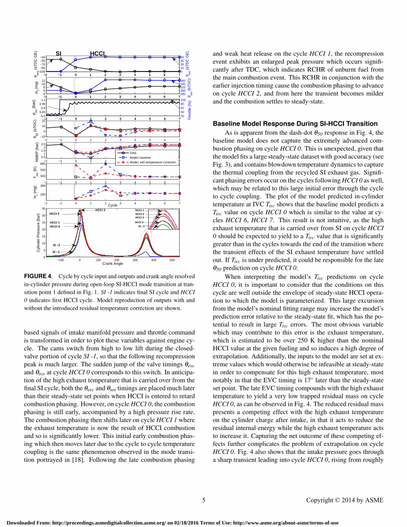
FIGURE 4. Cycle by cycle input and outputs and crank angle resolvedin-cylinder pressure during open-loop SI-HCCI mode transition at tran-sition point 1 defined in Fig. 1. SI -1 indicates final SI cycle and HCCI0 indicates first HCCI cycle. Model reproduction of outputs with andwithout the introduced residual temperature correction are shown.
based signals of intake manifold pressure and throttle commandis transformed in order to plot these variables against engine cy-cle. The cams switch from high to low lift during the closed-valve portion of cycle SI -1, so that the following recompressionpeak is much larger. The sudden jump of the valve timings θevcand θivo at cycle HCCI 0 corresponds to this switch. In anticipa-tion of the high exhaust temperature that is carried over from thefinal SI cycle, both the θevc and θsoi timings are placed much laterthan their steady-state set points when HCCI is entered to retardcombustion phasing. However, on cycle HCCI 0, the combustionphasing is still early, accompanied by a high pressure rise rate.The combustion phasing then shifts later on cycle HCCI 1 wherethe exhaust temperature is now the result of HCCI combustionand so is significantly lower. This initial early combustion phas-ing which then moves later due to the cycle to cycle temperaturecoupling is the same phenomenon observed in the mode transi-tion portrayed in [18]. Following the late combustion phasing
and weak heat release on the cycle HCCI 1, the recompressionevent exhibits an enlarged peak pressure which occurs signifi-cantly after TDC, which indicates RCHR of unburnt fuel fromthe main combustion event. This RCHR in conjunction with theearlier injection timing cause the combustion phasing to advanceon cycle HCCI 2, and from here the transient becomes milderand the combustion settles to steady-state.
Baseline Model Response During SI-HCCI TransitionAs is apparent from the dash-dot θ50 response in Fig. 4, the
baseline model does not capture the extremely advanced com-bustion phasing on cycle HCCI 0. This is unexpected, given thatthe model fits a large steady-state dataset with good accuracy (seeFig. 3), and contains blowdown temperature dynamics to capturethe thermal coupling from the recycled SI exhaust gas. Signifi-cant phasing errors occur on the cycles following HCCI 0 as well,which may be related to this large initial error through the cycleto cycle coupling. The plot of the model predicted in-cylindertemperature at IVC Tivc shows that the baseline model predicts aTivc value on cycle HCCI 0 which is similar to the value at cy-cles HCCI 6, HCCI 7. This result is not intuitive, as the highexhaust temperature that is carried over from SI on cycle HCCI0 should be expected to yield to a Tivc value that is significantlygreater than in the cycles towards the end of the transition wherethe transient effects of the SI exhaust temperature have settledout. If Tivc is under predicted, it could be responsible for the lateθ50 prediction on cycle HCCI 0.
When interpreting the model’s Tivc predictions on cycleHCCI 0, it is important to consider that the conditions on thiscycle are well outside the envelope of steady-state HCCI opera-tion to which the model is parameterized. This large excursionfrom the model’s nominal fitting range may increase the model’sprediction error relative to the steady-state fit, which has the po-tential to result in large Tivc errors. The most obvious variablewhich may contribute to this error is the exhaust temperature,which is estimated to be over 250 K higher than the nominalHCCI value at the given fueling and so induces a high degree ofextrapolation. Additionally, the inputs to the model are set at ex-treme values which would otherwise be infeasible at steady-statein order to compensate for this high exhaust temperature, mostnotably in that the EVC timing is 17◦ later than the steady-stateset point. The late EVC timing compounds with the high exhausttemperature to yield a very low trapped residual mass on cycleHCCI 0, as can be observed in Fig. 4. The reduced residual masspresents a competing effect with the high exhaust temperatureon the cylinder charge after intake, in that it acts to reduce theresidual internal energy while the high exhaust temperature actsto increase it. Capturing the net outcome of these competing ef-fects further complicates the problem of extrapolation on cycleHCCI 0. Fig. 4 also shows that the intake pressure goes througha sharp transient leading into cycle HCCI 0, rising from roughly
5 Copyright © 2014 by ASME
Downloaded From: http://proceedings.asmedigitalcollection.asme.org/ on 02/18/2016 Terms of Use: http://www.asme.org/about-asme/terms-of-use
0.55 to 1 bar in approximately 20 milliseconds. This sharp tran-sient may perturb the inducted air charge relative to what wouldotherwise be present at steady-state with the given intake pres-sure, which will go onto affect the in-cylinder temperature. Togain a better understanding of these effects on cycle HCCI 0 anddeduce whether the model’s θ50 error on cycle HCCI 0 stemsfrom error in it’s predicted Tivc, a crank-angle based simulationof the SI-HCCI mode transition is presented next.
Mode Transition Predictions Using Crank-Angle BasedModel
For a higher fidelity estimate of the in-cylinder dynamicsduring the SI-HCCI mode transition from which to draw con-clusions about the source of model error, a simplified single-cylinder GT-Power simulation was carried out. Measured intakeand exhaust manifold pressures and temperatures were specifiedas intake and exhaust runner boundary conditions on a crankangle basis, and the valve profiles/timings from the experimentwere imposed to capture the effect of the cam switch from high tolow lift and rapid cam phasing. To validate the GT-Power simula-tion, the experimental pressure traces are compared versus thosegenerated by the simulation in Fig. 5. The GT-Power simulationmatches experiment with satisfactory accuracy which indicatesthat its predictions should be reasonable.
0 100 200 300 400 500 600
5
10
15
20
Cyl
. Pre
ssur
e (b
ar) SI −2
0 100 200 300 400 500 600
5
10
15
20
Cyl
. Pre
ssur
e (b
ar) SI −1
0 100 200 300 400 500 600
10
20
30
Cyl
. Pre
ssur
e (b
ar) HCCI 0
Crank Angle0 100 200 300 400 500 600
5
10
15
20
25
Cyl
. Pre
ssur
e (b
ar) HCCI 1
Crank Angle
DataGT−Power
FIGURE 5. Comparison of experimental versus GT-Power simulationin-cylinder pressure during an SI-HCCI mode transition.
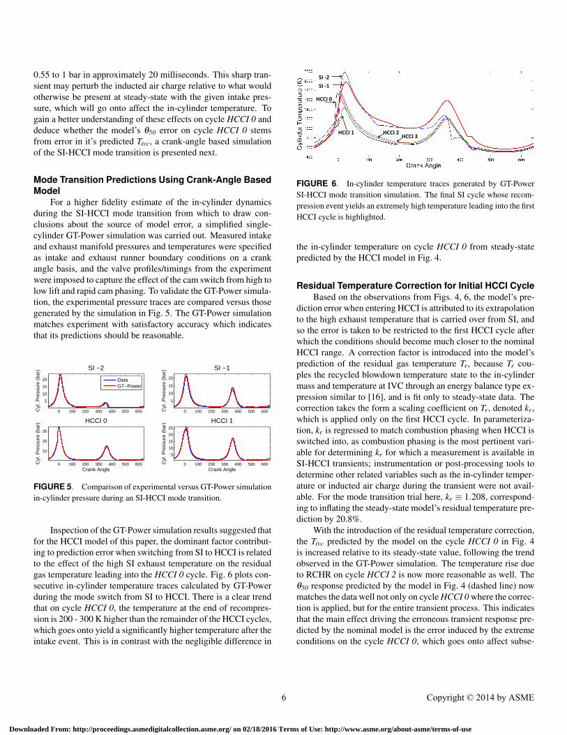
Inspection of the GT-Power simulation results suggested thatfor the HCCI model of this paper, the dominant factor contribut-ing to prediction error when switching from SI to HCCI is relatedto the effect of the high SI exhaust temperature on the residualgas temperature leading into the HCCI 0 cycle. Fig. 6 plots con-secutive in-cylinder temperature traces calculated by GT-Powerduring the mode switch from SI to HCCI. There is a clear trendthat on cycle HCCI 0, the temperature at the end of recompres-sion is 200 - 300 K higher than the remainder of the HCCI cycles,which goes onto yield a significantly higher temperature after theintake event. This is in contrast with the negligible difference in
SI -2
SI -1
HCCI 0
HCCI 1 HCCI 2 HCCI 3
FIGURE 6. In-cylinder temperature traces generated by GT-PowerSI-HCCI mode transition simulation. The final SI cycle whose recom-pression event yields an extremely high temperature leading into the firstHCCI cycle is highlighted.
the in-cylinder temperature on cycle HCCI 0 from steady-statepredicted by the HCCI model in Fig. 4.
Residual Temperature Correction for Initial HCCI CycleBased on the observations from Figs. 4, 6, the model’s pre-
diction error when entering HCCI is attributed to its extrapolationto the high exhaust temperature that is carried over from SI, andso the error is taken to be restricted to the first HCCI cycle afterwhich the conditions should become much closer to the nominalHCCI range. A correction factor is introduced into the model’sprediction of the residual gas temperature Tr, because Tr cou-ples the recycled blowdown temperature state to the in-cylindermass and temperature at IVC through an energy balance type ex-pression similar to [16], and is fit only to steady-state data. Thecorrection takes the form a scaling coefficient on Tr, denoted kr,which is applied only on the first HCCI cycle. In parameteriza-tion, kr is regressed to match combustion phasing when HCCI isswitched into, as combustion phasing is the most pertinent vari-able for determining kr for which a measurement is available inSI-HCCI transients; instrumentation or post-processing tools todetermine other related variables such as the in-cylinder temper-ature or inducted air charge during the transient were not avail-able. For the mode transition trial here, kr ≡ 1.208, correspond-ing to inflating the steady-state model’s residual temperature pre-diction by 20.8%.
With the introduction of the residual temperature correction,the Tivc predicted by the model on the cycle HCCI 0 in Fig. 4is increased relative to its steady-state value, following the trendobserved in the GT-Power simulation. The temperature rise dueto RCHR on cycle HCCI 2 is now more reasonable as well. Theθ50 response predicted by the model in Fig. 4 (dashed line) nowmatches the data well not only on cycle HCCI 0 where the correc-tion is applied, but for the entire transient process. This indicatesthat the main effect driving the erroneous transient response pre-dicted by the nominal model is the error induced by the extremeconditions on the cycle HCCI 0, which goes onto affect subse-
6 Copyright © 2014 by ASME
Downloaded From: http://proceedings.asmedigitalcollection.asme.org/ on 02/18/2016 Terms of Use: http://www.asme.org/about-asme/terms-of-use

quent cycles though the cycle to cycle states. Once this error iscorrected for, the nominal model can capture the remainder ofthe transient response, as the conditions become much closer tothe nominal HCCI range. Throughout the transient, the model isable to capture the effects of varying fuel quantity, injection tim-ing, EVC timing, as well as any variations in AFR due to rapidchanges in these actuators.
Validation with a Different SI-HCCI Transition Se-quence
To corroborate the modeling approach, the model is exer-cised to simulate a mode transition sequence at transition point 2defined in Fig. 1. This represents a transition an operating pointthat is approximately 0.5 bar NMEP higher than the case previ-ously considered, or roughly 25% of the HCCI load range at 2000RPM on the experimental engine. The initial conditions for thefirst HCCI cycle at this operating condition are estimated to be[T 0
bd ,b0bd , f 0
bd ] = [980 K,0.823,0], where the only slightly higherblowdown temperature estimate is the result of a leaner mixtureon the final SI cycle where λ = 1.3. The model parameters,including the residual temperature correction kr, are unchangedfrom the their values at transition point 1. The model predictionsof the performance outputs θ50 and NMEP along with the impor-tant combustion inputs are plotted in Fig. 7. Again it can be seenthe model reproduces the combustion outputs well. The abilityof the model to reproduce this alternate SI-HCCI mode transitionwithout adjusting the kr value may suggest that kr has only a mildsensitivity to operating condition. However, to definitively deter-mine the degree of variation and potential regression/tabulationof kr versus operation condition, more SI-HCCI transition dataover a wider range of conditions are necessary.
CONCLUSIONSA low-order HCCI combustion model extended to capture
SI-HCCI mode transition data with two-stage cam switchingstrategies has been presented. The model was shown to fitsteady-state data over a wide range of conditions, including throt-tled HCCI and rich to very lean AFRs which may be encounteredin two-stage cam switching mode transitions strategies. Despitethe adequate steady-state accuracy, the model’s predicted re-sponse exhibited significant error when simulated with SI-HCCImode transition data. The origin of of this error was traced tothe extreme conditions on the first HCCI cycle when switchingfrom SI to HCCI, which are well outside the nominal HCCI op-erating range. The dominant factor contributing to the predictionerror was found to be related to the high exhaust temperaturethat is carried over from SI, and so a correction factor whichaccounts for the error through the residual gas temperature wasintroduced. With the correction factor in place, the model repro-duced transient performance output time histories well for two
−2 −1 0 1 2 3 4 5 6 7−10
0
10
θ 50 (
aTD
C)
SI HCCI
DataModel
−2 −1 0 1 2 3 4 5 6 7
1
2
3
NM
EP
(ba
r)
Cycle
−2 −1 0 1 2 3 4 5 6 7−100
−85
−70
−55
−40
θ evc (
aTD
C G
E)
−2 −1 0 1 2 3 4 5 6 70
15
30
45
60
θ ivo (
aTD
C G
E)
−2 −1 0 1 2 3 4 5 6 74
6
8
10
12
mf (
mg)
−2 −1 0 1 2 3 4 5 6 7280
300
320
340
360
θ soi (
bTD
C)
FIGURE 7. SI-HCCI mode transition simulation at transition point 2defined in Fig. 1. Steady-state model parameters and SI-HCCI residualtemperature correction factor are unchanged from transition point 1.
different SI-HCCI mode transition sequences.Further investigation of the in-cylinder phenomena when
switching from SI to HCCI and evaluation of the proposed resid-ual gas temperature correction method over a wider range of SI-HCCI transitions is planned for future work. Additionally, ex-tension of the low-order HCCI modeling approach of this paperto encompass the effects of spark assist is a pertinent topic forfuture research, as many mode transition studies [4,5,7,9,11,26]have found spark assist to be helpful.
ACKNOWLEDGMENTThis material is based upon work supported by the Depart-
ment of Energy [National Energy Technology Laboratory] underAward Number(s) DE-EE0003533. 1 This work is performed asa part of the ACCESS project consortium (Robert Bosch LLC,AVL Inc., Emitec Inc., Stanford University, University of Michi-
1Disclaimer: This report was prepared as an account of work sponsored by an agencyof the United States Government. Neither the United States Government nor any agencythereof, nor any of their employees, makes any warranty, express or implied, or assumes anylegal liability or responsibility for the accuracy, completeness, or usefulness of any informa-tion, apparatus, product, or process disclosed, or represents that its use would not infringeprivately owned rights. Reference herein to any specific commercial product, process, orservice by trade name, trademark, manufacturer, or otherwise does not necessarily constituteor imply its endorsement, recommendation, or favoring by the United States Government orany agency thereof. The views and opinions of authors expressed herein do not necessarilystate or reflect those of the United States Government or any agency thereof.
7 Copyright © 2014 by ASME
Downloaded From: http://proceedings.asmedigitalcollection.asme.org/ on 02/18/2016 Terms of Use: http://www.asme.org/about-asme/terms-of-use

gan) under the direction of PI Hakan Yilmaz and Co-PI OliverMiersch-Wiemers, Robert Bosch LLC.
NOMENCLATUREbTDC/aTDC before/after Top Dead CenterIVO/IVC Intake Valve Opening/Closing timingEVO/EVC Exhaust Valve Opening/Closing timingRCHR Recompression Heat ReleaseAFR Air-Fuel Ratioλ/λc Relative AFR in the exhaust/cylinderTbd Temperature after blowdownbbd Burned gas fraction after blowdownfbd Unburnt fuel mass fraction after blowdownm f Fuel massmr Residual massθ50 Crank angle of 50% mass fraction burnedpim Pressure in intake manifoldNMEP/IMEP Net/Gross Indicated Mean Effective Pressureθivo/θevc Cam phaser IVO/EVC positionθsoi Start of fuel injection timingkr Residual gas temperature correction for SI-HCCI transition
References[1] Zhao, F., Asmus, T., Assanis, D., Dec, J., Eng, J., and Najt, P., 2003. Ho-
mogeneous Charge Compression Ignition (HCCI) Engines: Key Researchand Development Issues. SAE International.
[2] Koopmans, L., Strom, H., Lundgren, S., Backlund, O., and Denbratt, I.“Demonstrating a SI-HCCI-SI mode change on a Volvo 5-cylinder elec-tronic valve control engine”. SAE Technical Paper 2003-01-0753.
[3] Santoso, H., Matthews, J., and Cheng, W. “Managing SI/HCCI dual-modeengine operation”. SAE Technical Paper 2005-01-0162.
[4] Zhang, Y., Xie, H., Zhou, N., Chen, T., and Zhao, H. “Study of SI-HCCI-SI transition on a port fuel injection engine equipped with 4VVAS”. SAETechnical Paper 2007-01-0199.
[5] Milovanovic, N., Blundell, D., Gedge, S., and Turner, J. “SI-HCCI-SI modetransition at different engine operating conditions”. SAE Technical Paper2005-01-0156.
[6] Tian, G., Wang, Z., Ge, Q., Wang, J., and Shuai, S., 2007. “Control of aspark ignition homogeneous charge compression ignition mode transitionon a gasoline direct injection engine”. Proceedings of the Institution of Me-chanical Engineers, Part D: Journal of Automobile Engineering, 221(867).
[7] Cairns, A., and Blaxill, H. “The effects of two-stage cam profile switchingand external EGR on SI-CAI combustion transitions”. SAE Technical Paper2007-01-0187.
[8] Kalian, N., Zhao, H., and Qiao, J., 2008. “Investigation of transition be-tween spark ignition and controlled auto-ignition combustion in a v6 direct-injection engine with cam profile switching”. Proc. of the Institution ofMech. Engineers, Part D: J. Automobile Engineering, 222, pp. 1911–1926.
[9] Wu, H., Collings, N., Regitz, S., Etheridge, J., and Kraft, M. “Exper-imental investigation of a control method for SI-HCCI-SI transition in amulti-cylinder gasoline engine”. SAE Technical Paper 2010-01-1245.
[10] Nier, T., Kulzer, A., and Karrelmeyer, R. “Analysis of the combustionmode switch between SI and gasoline HCCI”. SAE Technical Paper 2012-01-1105.
[11] Kakuya, H., Yamaoka, S., Kumano, K., and Sato, S. “Investigation of a SI-HCCI combustion switching control method in a multi-cylinder gasolineengine”. SAE Technical Paper 2008-01-0792.
[12] Gorzelic, P., Hellstrom, E., Stefanopoulou, A., and Jiang, L., 2012. “Model-based feedback control for an automated transfer out of SI operating duringSI to HCCI transitions in gasoline engines”. ASME Dynamic Systems andControl Conference.
[13] Ravi, N., Jagsch, M., Oudart, J., Chaturvedi, N., Cook, D., and Kojic, A.,2013. “Closed-loop control of SI-HCCI mode switch using fuel injectiontiming”. ASME Dynamic Systems and Control Conference.
[14] Shaver, G., Gerdes, J., Roelle, M., Caton, P., and Edwards, C., 2005. “Dy-namic modeling of residual-affected homogeneous charge compression ig-nition engines with variable valve actuation”. J. Dyn. Sys. Meas. Control,127(3), pp. 374–81.
[15] Rausen, D., Stefanopoulou, A., Kang, J., Eng, J., and Kuo, T., 2005. “Amean value model for control of homogeneous charge compression ignition(HCCI) engines”. J. Dyn. Syst. Meas. Control, 127(3), pp. 355–362.
[16] Jade, S., Hellstrom, E., Larimore, J., Stefanopoulou, A., and Jiang, L., Toappear. “Reference governor for load control in a multicylinder recompres-sion HCCI engine”. IEEE Trans. Control Sys. Tech.
[17] Yang, X., and Zhu, G., 2011. “A two-zone control oriented SI-HCCI hybridcombustion model for the HIL engine simulation”. IEEE American ControlConference.
[18] Shaver, G., Roelle, M., and Gerdes, J., 2006. “Modeling cycle-to-cycledynamics and mode transition in HCCI engines with variable valve actua-tion”. Control Engineering Practice, 14, pp. 213–222.
[19] Ravi, N., Roelle, M., Liao, H., Jungkunz, A., Chang, C., Park, S., andGerdes, J., 2010. “Model-based control of HCCI engines using exhaustrecompression”. IEEE Trans. Control Sys. Tech., 18(6), pp. 1289–1302.
[20] Ravi, N., Liao, H.-H., Jungkunz, A., Chang, C.-F., Song, H., and Gerdes,J., 2012. “Modeling and control of an exhaust recompression HCCI engineusing split injection”. J. Dyn. Syst. Meas. Control, 134, pp. 231–250.
[21] Yun, H., Guralp, O., Grover, R., and Najt, P., 2013. “The effect of temper-ature and oxygen concentration on auto-ignition at low-load operating con-ditions in a gasoline homogeneous charge compression ignition engine”.Int. J. Engine Research, 14(5), pp. 512–524.
[22] He, X., Donovan, M., Zigler, B., Palmer, T., Walton, S., Woolridge, M.,and Atreya, A., 2005. “An experimental and modeling study of iso-octaneignition delay times under homogeneous charge compression ignition con-ditions”. Combustion and Flame, 142, pp. 266–275.
[23] Song, H. H., and Edwards, C. F., 2009. “Understanding chemical effectsin low-load-limit extension of homogeneous charge compression ignitionengines via recompression reaction”. Int. J. Engine Research, 10, pp. 231–250.
[24] Hellstrom, E., Larimore, L., Stefanopoulou, A., Sterniak, J., and Jiang, L.,2012. “Quantifying cyclic variabilityin a multicylinder HCCI engine withhigh residuals”. J. Eng. for Gas Turb. and Power, 134(11), pp. 112803–1–8.
[25] Hellstrom, E., and Stefanopoulou, A., 2011. “Modeling cyclic dispersionin autoignition combustion”. IEEE Conference on Decision and Control.
[26] Matsuda, T., Wada, H., Kono, T., Nakamura, T., and Urushihara, T. “Astudy of a gasoline-fueled HCCI engine mode changes from SI combustionto HCCI combustion”. SAE Technical Paper 2008-01-0050.
8 Copyright © 2014 by ASME
Downloaded From: http://proceedings.asmedigitalcollection.asme.org/ on 02/18/2016 Terms of Use: http://www.asme.org/about-asme/terms-of-use