
A knowledge-based framework for software evolution control
16
A knowledge-based framework for software evolution control Adeel Ahmad, Henri Basson, Laurent Deruelle, Mourad Bouneffa Laboratoire d’Informatique du Littoral, Maison de la recherche Blaise Pascal 50, rue Ferdinand Buisson - BP 719, 62228, Calais Cedex, France {ahmad, basson, deruelle, bouneffa}@lil.univ-littoral.fr ABSTRACT. An exhaustive software description is required for better understanding and analysis of different impacts of intended change. A change applied on a software artefact can propagate its impact on several other components of whole system. This impact can be considered from structural, qualitative, functional, logical, or behavioural point of view. In this article, we describe a Knowledge-Based System encompassing a large set of knowledge describing exhaustively software application targeted by change. This knowledge set is built in reference to a proposed Generic Software Model for Software Evolution. As a knowledge- based system, it manages a rule repository of application knowledge (Fact-Base) in interaction with a Rule-Base aiming at including rules destined to better handling of the future changes. A framework for better change impact analysis of software applications is first generally presented to demonstrate afterwards in detail how it can be used to control change impact propagation throughout different links between concerned software artefacts. RÉSUMÉ. Une description exhaustive de logiciels est nécessaire pour une meilleure compréhension et une analyse des différents impacts des modifications. Une modification appliquée sur un artefact logiciel peut propager son impact sur plusieurs autres composants de l’ensemble du système. Cet impact peut être considéré d’un point de vue structurel, qualitatif, fonctionnel, logique, ou comportemental. Dans cet article, nous décrivons un système à base de connaissances qui englobe un large ensemble de connaissances décrivant de façon exhaustive les applications logicielles visées par le changement. Cet ensemble est construit en référence à un modèle générique pour l’évolution des logiciels. En tant que système à base de connaissances, il gère un répertoire de règles relatives à l’application en cours (Fact-Base), en interaction avec une base des règles incluant celles destinées à la gestion des futurs changements. Un cadre pour une meilleure analyse de l'impact des changements de logiciels est d’abord globalement présenté, il est ensuite démontré en détail comment il peut être utilisé pour le contrôle de la propagation de l'impact des modifications à travers les différents liens existant entre les artefacts logiciels concernés par le changement en cours. KEYWORDS: software evolution, change impact propagation, Generic Model of Software Evolution, Knowledge-Based System. MOTS-CLÉS: évolution de logiciels, le propagation d’impact de modification, Modèle Générique pour l’Evolution des Logiciels, Système à Base de Connaissance. Actes du XXVII° congrès INFORSID, Toulouse, mai 2009 111
-
Upload
independent -
Category
Documents
-
view
1 -
download
0
Transcript of A knowledge-based framework for software evolution control
A knowledge-based framework for software evolution control
Adeel Ahmad, Henri Basson, Laurent Deruelle, Mourad Bouneffa Laboratoire d’Informatique du Littoral, Maison de la recherche Blaise Pascal
50, rue Ferdinand Buisson - BP 719, 62228, Calais Cedex, France
{ahmad, basson, deruelle, bouneffa}@lil.univ-littoral.fr
ABSTRACT. An exhaustive software description is required for better understanding and analysis
of different impacts of intended change. A change applied on a software artefact can
propagate its impact on several other components of whole system. This impact can be
considered from structural, qualitative, functional, logical, or behavioural point of view. In
this article, we describe a Knowledge-Based System encompassing a large set of knowledge
describing exhaustively software application targeted by change. This knowledge set is built
in reference to a proposed Generic Software Model for Software Evolution. As a knowledge-
based system, it manages a rule repository of application knowledge (Fact-Base) in
interaction with a Rule-Base aiming at including rules destined to better handling of the
future changes. A framework for better change impact analysis of software applications is
first generally presented to demonstrate afterwards in detail how it can be used to control
change impact propagation throughout different links between concerned software artefacts.
RÉSUMÉ. Une description exhaustive de logiciels est nécessaire pour une meilleure
compréhension et une analyse des différents impacts des modifications. Une modification
appliquée sur un artefact logiciel peut propager son impact sur plusieurs autres composants
de l’ensemble du système. Cet impact peut être considéré d’un point de vue structurel,
qualitatif, fonctionnel, logique, ou comportemental. Dans cet article, nous décrivons un
système à base de connaissances qui englobe un large ensemble de connaissances décrivant
de façon exhaustive les applications logicielles visées par le changement. Cet ensemble est
construit en référence à un modèle générique pour l’évolution des logiciels. En tant que
système à base de connaissances, il gère un répertoire de règles relatives à l’application en
cours (Fact-Base), en interaction avec une base des règles incluant celles destinées à la
gestion des futurs changements. Un cadre pour une meilleure analyse de l'impact des
changements de logiciels est d’abord globalement présenté, il est ensuite démontré en détail
comment il peut être utilisé pour le contrôle de la propagation de l'impact des modifications
à travers les différents liens existant entre les artefacts logiciels concernés par le changement
en cours.
KEYWORDS: software evolution, change impact propagation, Generic Model of Software
Evolution, Knowledge-Based System.
MOTS-CLÉS: évolution de logiciels, le propagation d’impact de modification, Modèle
Générique pour l’Evolution des Logiciels, Système à Base de Connaissance.
Actes du XXVII° congrès INFORSID, Toulouse, mai 2009
111

1. Introduction
Software evolution management is a crucial sub-domain of information system
engineering tackling the problems associated with post-development changes.
Software evolution may occur at random intervals of time, generating new cycles of
change design, implementation, and retest. The research in software evolution has
been targeted to minimize the undesired change side effects throughout several
software components.
Uncontrolled changes in a software can result into complex and numerous
undesired effects. The complexity of inter components relationships aggravates
software regression and makes more difficult to isolate the causal flows leading to
unexpected effects. Moreover, change impact analysis remains very difficult to
realize by generating and maintaining empirical data, enough significant, to elaborate
reliable causal flow.
Traditional approaches in understanding software evolution include the use of
history of software systems to analyze their present state and predict future changes
(Gall et al., 1997) complemented by existing reverse engineering approaches
(Ambros et al., 2006; Lungu et al., 2007; Huzefa et al., 2006; Rumbaugh et al.,
2005; Rysselberghe et al., 2004). Refactoring has also been proposed by Fowler
(1999) as a way of preventing the software quality decay. However, these techniques
are time consuming. Also, such manual extraction of data by both techniques at
explicit requests by the development engineers may not be sufficient to have higher
quality information for software evolution (Robbes, 2007).
Software evolution often generate structural, qualitative, functional, logical, or
behavioral variations (Ahmad et al., 2008a). Subsequently, an a priori change
impact analysis require exhaustive description of all software artefacts which would
be affected by the intended change (Ahmad et al., 2008b). This necessitates the
storage and manipulation of a large set of software description data. Traditionally
adopted approaches for these empirical studies require costly data collection (often
manual) and complex statistical analysis. This article describes a framework for
simulating software evolution using a Knowledge-Based System as a repository for
software specific information. The data in knowledge base is inserted with instances
of Generic Model of Software Evolution (GMSE). This framework uses an
automotive collection of software specific information. Once the information is
extracted, it can be manipulated with less help of experts. The collected information
is used as a seed. Thereafter, in case of any intended change, analysis can be run
repeatedly to extend the available information. Furthermore, maintaining history of
change reasons and affected software artefacts provide additional aid to make the
task easier and more efficient than using traditional empirical methods or refactoring
techniques; which also provides the basic motivation for the research described in
this article.
Actes du XXVII° congrès INFORSID, Toulouse, mai 2009
112
In the following sections, we first present and discuss proposed model GMSE
(Generic Model for Software Evolution) and its elaboration in section 2. Then, we
present the construction of KBS in section 3 and the construction of rules considered
and modeled by GMSE (section 4). We discuss the rule generation for change impact
analysis and change propagation process based on description of software
components and different occurrences of relationship types between components.
Later, we show the implementation of semi-automated Expert System (section 5)
with extracted facts as the instantiation of GMSE and rule based propagation.
2. Generic Model of Software Evolution
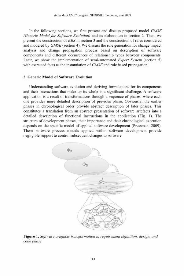
Understanding software evolution and deriving formulations for its components
and their interactions that make up its whole is a significant challenge. A software
application is a result of transformations through a sequence of phases, where each
one provides more detailed description of previous phase. Obviously, the earlier
phases in chronological order provide abstract description of later phases. This
constitutes a translation from an abstract presentation of software artefacts into a
detailed description of functional instructions in the application (Fig. 1). The
structure of development phases, their importance and their chronological execution
depends on the specific model of applied software development (Pressman, 2009).
These software process models applied within software development provide
negligible support to control subsequent changes to software.
Figure 1. Software artefacts transformation in requirement definition, design, and
code phase
Actes du XXVII° congrès INFORSID, Toulouse, mai 2009
113
In this section, we present a Generic Model of Software Evolution intended to
trace the change impact propagation among interrelated software artefacts. We
consider the common phases as shared by all major development models (waterfall,
V, Spiral, Incremental, Evolutionary, Transformational, Agile, Rapid Prototyping
etc.). Each phase is animated by a set of activities, to achieve its designated
purposes, which are managed and accomplished by software development actors.
Every actor is attributed with defined role to accomplish the assigned activity.
Software source code is written in some programming languages according to some
methods, techniques and standards. In each development phase, a set of tools is used
to support animated activities to accomplish artefact description, achievement, or
testing etc.. We denote a software phase as set Φ, actors as Atr, activities as Aty,
artefacts as Art, methods as Mtd, languages as Lng, and software tools as Stl. To the
set of phases (∑Φ) of the whole project corresponds the high level description of
phases (d∑Φ) specified as:
d∑Φ = < d∑Atr, d∑Aty, d∑Art, d∑Mtd, d∑Lng, d∑Stl >
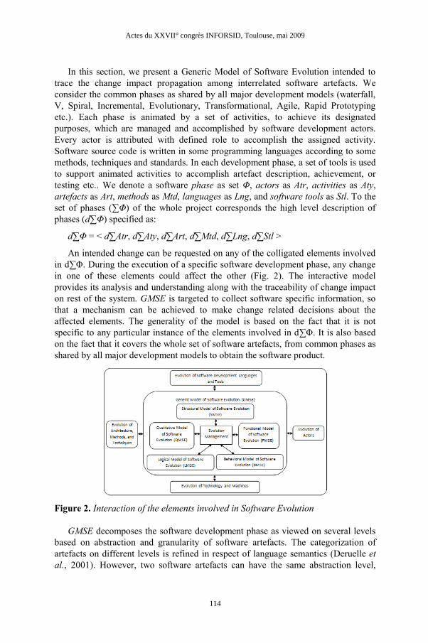
An intended change can be requested on any of the colligated elements involved
in d∑Φ. During the execution of a specific software development phase, any change
in one of these elements could affect the other (Fig. 2). The interactive model
provides its analysis and understanding along with the traceability of change impact
on rest of the system. GMSE is targeted to collect software specific information, so
that a mechanism can be achieved to make change related decisions about the
affected elements. The generality of the model is based on the fact that it is not
specific to any particular instance of the elements involved in d∑Φ. It is also based
on the fact that it covers the whole set of software artefacts, from common phases as
shared by all major development models to obtain the software product.
Figure 2. Interaction of the elements involved in Software Evolution
GMSE decomposes the software development phase as viewed on several levels
based on abstraction and granularity of software artefacts. The categorization of
artefacts on different levels is refined in respect of language semantics (Deruelle et
al., 2001). However, two software artefacts can have the same abstraction level,
Actes du XXVII° congrès INFORSID, Toulouse, mai 2009
114
without having same granularity level, e.g. in the object oriented paradigm, fields
and methods are on the same level of abstraction, but on different levels of
granularity. In the same way two software artefacts can have the same granularity
level without having the same abstraction level, e.g. a generic class indeed can be on
the same level of granularity of a very short class, but they belong to different levels
of abstraction.
Software artefacts are inter-linked with some relationship type occurrences,
which is the basic entity that provides a path for the change impact flow. GMSE
classify the relationship type as being one of the Inter-phase, Inter-level, or Intra-
level relationships. An Inter-phase relationship is a bi-directional relationship which
represent traceability links between artefacts issued from two different development
phases. As discussed, each phase has different levels. Therefore, in case of a change,
we analyze the inter-level and intra level relationships, within and among these
levels, and that progressively in each phase as well as between different phases.
The potential of a relationship occurrence to propagate a change impact from one
of the participating artefacts to another linked artefact qualifies its change impact
conductivity. This highly depends on the relationship type occurrence and its
cardinalities. A relationship cardinality encapsulates the properties characterizing the
conditions and iterations of occurrences of such relationship. Hence, change impact
analysis and conductivity of a relationship wouldn’t be effective until all the relevant
cardinalities of the relationship type are considered. In addition, cardinalities
regarding the occurrence of a relationship type caused by a certain change, will be
used to identify affected artefacts and provides a set of attributes which permits to
qualify, more precisely, the change impact conductivity.
A successful software change incorporation process may require to understand
the change impact propagation considering several aspect to prevent the software
decay. The proposed GMSE model comprises the common elements to trace the
structural, qualitative, functional, logical, and behavioral aspects of change impact
propagation. It will be further extended by Structural Model of Software
Evolution(SMSE), Qualitative Model of Software Evolution(QMSE), Functional
Model of Software Evolution(FMSE), Logical Model of Software Evolution(LMSE),
and Behavioral Model of Software Evolution(BMSE). This inheritance of GMSE can
provide its implementation for the generation of empirical data describing a specific
aspect of change propagation. This constitutes a large set of data to be maintained.
Particularly, the change relevant information of artefacts, involved relationship
types, and specified change propagation aspect. This provides the basic motivation
of model execution with the help of a knowledge base.
3. Knowledge-Based System for Software Evolution
Knowledge-Based System for Software Evolution (KBSSE) provides the meta
information regarding software artefacts constituting software application to control
Actes du XXVII° congrès INFORSID, Toulouse, mai 2009
115

the change. The representation of information follows some basic axioms that we
describe later in next section. These axioms are meant to control the software
evolution by providing descriptive knowledge of software behavior in case of a
certain change. We also deduce some corollaries based on these axioms and define
rules to follow the change impact propagation. This constitutes a rule-base for our
knowledge-based system.
The KBSSE also follows the intuitive or pragmatic knowledge, which may not
necessarily require proofs. These correspond to related heuristics of a particular
domain and express information or techniques gained (Melab et al., 2001). This
knowledge represented as rules can generate effective rules, to maintain the sequence
of their implementation and execution.
KBSSE is a complete rule management system for software applications to
incorporate changes. The two major parts involved in its constitution are fact-base
and rule-base. Fact-base is a repository of extracted facts of the software application
and it works in conjunction with the rule-base. The extracted facts results from the
execution of our pre-defined model GMSE, on software artefacts. Rule-base is
composed of rule engine and rule specification. The Rule Engine is rule generator
for an invoked relationship type and its cardinalities. The rule specification contains
the comprehensive details regarding the impact of software modification action to be
taken and relevant history of decisions. It helps in tracing the impact of change on a
particular software artefact and supports decision making during incorporation of
changes.
Figure 3. Generation of rule in Knowledge-Based System for Software Evolution
Whenever, an external change is intended on software application the event
detector triggers a requirement for maintenance in fact-base (Fig. 3). This activates
the rule engine of rule-base to consult the relevant effects. Consequently, a rule
would be created detailing the specification of change impact and actions in this
accord, in rule specification. The rule specification part iteratively invokes the rule
engine to construct the change impact flow in affected artefacts. The impact flow
path is constructed accordingly through relationship types carrying the direct impact
and then iteratively by the impact propagation on each affected artefact.
Actes du XXVII° congrès INFORSID, Toulouse, mai 2009
116
4. Generating rules to trace the change impact propagation
It is important to determine the extent to which an artefact is affected by a change
operated on another linked artefact. The creation of rules for change impact
propagation is based on the descriptive knowledge of the cardinalities of relationship
type among artefacts and its preliminary evaluation of conductivity in case of
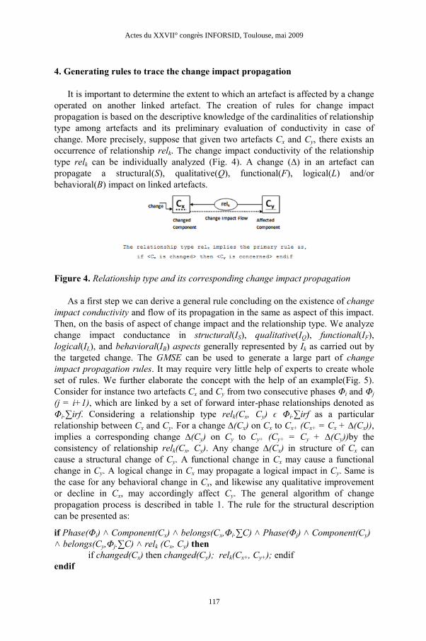
change. More precisely, suppose that given two artefacts Cx and Cy, there exists an
occurrence of relationship relk. The change impact conductivity of the relationship
type relk can be individually analyzed (Fig. 4). A change (∆) in an artefact can
propagate a structural(S), qualitative(Q), functional(F), logical(L) and/or
behavioral(B) impact on linked artefacts.
Figure 4. Relationship type and its corresponding change impact propagation
As a first step we can derive a general rule concluding on the existence of change
impact conductivity and flow of its propagation in the same as aspect of this impact.
Then, on the basis of aspect of change impact and the relationship type. We analyze
change impact conductance in structural(IS), qualitative(IQ), functional(IF),
logical(IL), and behavioral(IB) aspects generally represented by Ik as carried out by
the targeted change. The GMSE can be used to generate a large part of change
impact propagation rules. It may require very little help of experts to create whole
set of rules. We further elaborate the concept with the help of an example(Fig. 5).
Consider for instance two artefacts Cx and Cy from two consecutive phases Φi and Φj
(j = i+1), which are linked by a set of forward inter-phase relationships denoted as
Φi.∑irf. Considering a relationship type relk(Cx, Cy) ϵ Φi.∑irf as a particular
relationship between Cx and Cy. For a change ∆(Cx) on Cx to Cx+ (Cx+ = Cx + ∆(Cx)),
implies a corresponding change ∆(Cy) on Cy to Cy+ (Cy+ = Cy + ∆(Cy))by the
consistency of relationship relk(Cx, Cy). Any change ∆(Cx) in structure of Cx can
cause a structural change of Cy. A functional change in Cx may cause a functional
change in Cy. A logical change in Cx may propagate a logical impact in Cy. Same is
the case for any behavioral change in Cx, and likewise any qualitative improvement
or decline in Cx, may accordingly affect Cy. The general algorithm of change
propagation process is described in table 1. The rule for the structural description
can be presented as:
if Phase(Φi) ˄ Component(Cx) ˄ belongs(Cx,Φi.∑C) ˄ Phase(Φj) ˄ Component(Cy)
˄ belongs(Cy,Φj.∑C) ˄ relk (Cx, Cy) then
if changed(Cx) then changed(Cy); relk(Cx+, Cy+); endif
endif
Actes du XXVII° congrès INFORSID, Toulouse, mai 2009
117
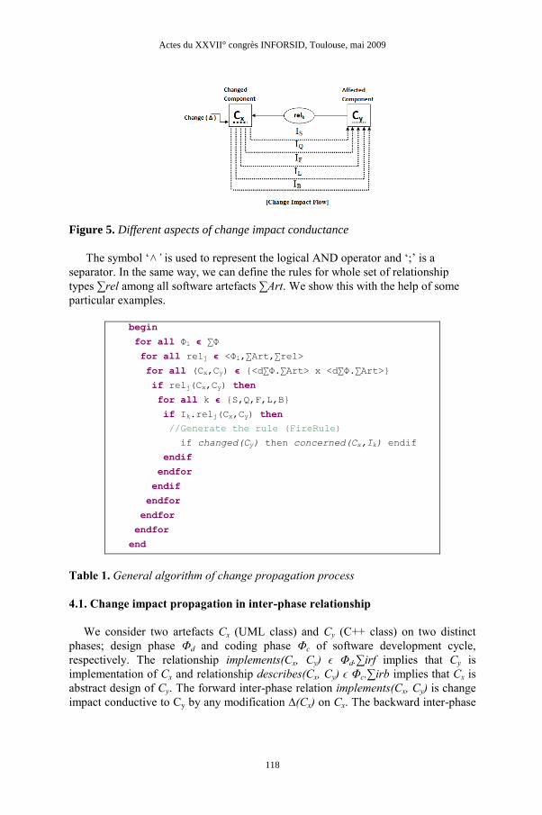
Figure 5. Different aspects of change impact conductance
The symbol ‘˄’ is used to represent the logical AND operator and ‘;’ is a
separator. In the same way, we can define the rules for whole set of relationship
types ∑rel among all software artefacts ∑Art. We show this with the help of some
particular examples.
begin
for all Φi ϵ ∑Φ
for all relj ϵ <Φi,∑Art,∑rel>
for all (Cx,Cy) ϵ {<d∑Φ.∑Art> x <d∑Φ.∑Art>}
if relj(Cx,Cy) then
for all k ϵ {S,Q,F,L,B}
if Ik.relj(Cx,Cy) then
//Generate the rule (FireRule)
if changed(Cy) then concerned(Cx,Ik) endif
endif
endfor
endif
endfor
endfor
endfor
end
Table 1. General algorithm of change propagation process
4.1. Change impact propagation in inter-phase relationship
We consider two artefacts Cx (UML class) and Cy (C++ class) on two distinct
phases; design phase Φd and coding phase Φc of software development cycle,
respectively. The relationship implements(Cx, Cy) ϵ Φd.∑irf implies that Cy is
implementation of Cx and relationship describes(Cx, Cy) ϵ Φc.∑irb implies that Cx is
abstract design of Cy. The forward inter-phase relation implements(Cx, Cy) is change
impact conductive to Cy by any modification ∆(Cx) on Cx. The backward inter-phase
Actes du XXVII° congrès INFORSID, Toulouse, mai 2009
118
relation describes(Cx, Cy) is change impact conductive to Cx by any modification
∆(Cy) on Cy.
The rule for change impact propagation for describes(Cx, Cy) can be expressed as:
if Phase(Φd) ˄ Component(Cx) ˄ belongs(Cx,Φd.∑C) ˄ Phase(Φc) ˄ Component(Cy)
˄ belongs(Cy,Φc.∑C) ˄ describes(Cx, Cy) then
if changed(Cy) then changed(Cx) ; describes(Cx+, Cy+); endif
endif
The relationship describes(Cx, Cy) is specialized to implements(Cx, Cy) then rule
for its conductivity of change impact propagation can be expressed as follows:
if Phase(Φd) ˄ Component(Cx) ˄ belongs(Cx,Φd.∑C) ˄ Phase(Φc) ˄ Component(Cy)
˄ belongs(Cy,Φc.∑C) ˄ implements(Cx, Cy) then
if changed(Cx) then changed(Cy); implements(Cx+, Cy+); endif
endif
4.2. Change impact propagation in inter-level relationship
We consider, for illustration, three artefacts Cx, Cy, and Cz in coding phase (Φc) of
software development cycle. Cx and Cy is a couple of modules on modules level
represented as (Cx, Cy ϵ <Lvmod, ∑mod>). Cz is an artefact of individual symbols on
individual symbol level represented as (Cz ϵ <Lvsym, ∑sym>). Cz is visible to both Cx
and Cy. The vertical relation modifies(Cy, Cz) ϵ Φc.∑vr implies that Cy is able to
modify the Cz. The vertical relation uses(Cx, Cz) ϵ Φc.∑vr implies that Cx is able to
use Cz. Any modification ∆(Cz) on Cz by Cy may affect the Cx.
The rule for conductivity of change impact propagation can be expressed as
follows:
if Phase(Φc) ˄ Level(Lvmod) ˄ Component(Cx) ˄ belongs(Cx,Φc. Lvmod.∑mod) ˄
Phase(Φc) ˄ Level(Lvmod) ˄ Component(Cy) ˄ belongs(Cy,Φc. Lvmod.∑mod) ˄
Phase(Φc) ˄ Level(Lvsym) ˄ Component(Cz) ˄ belongs(Cz,Φc. Lvsym.∑sym) ˄
uses(Cx, Cz) ˄ modifies(Cy, Cz) then
if modifies(Cy, Cz) ˄ changed(Cz) then changed(Cy) ; changed(Cx);
uses(Cx+, Cz+); modifies(Cy+, Cz+); endif
endif
4.3. Change impact propagation in intra-level relationship
We consider two artefacts Cx and Cy as a couple of modules in coding phase (Cx,
Cy ϵ <Φc, Lvmod, ∑mod>) such that Cy calls Cx. The horizontal calling relationship
(calls(Cx, Cy) ϵ Φc.∑hr) implies that any modification ∆(Cx) on the Cx (called
component) to Cx+ affects the Cy (calling component) and may cause a change ∆(Cy),
but the modifications in Cy have no impact on Cx. The extent to which Cy is
concerned with the change in Cx, depends obviously on the nature and the type of the
change.
Actes du XXVII° congrès INFORSID, Toulouse, mai 2009
119
The rule for its conductivity of change impact propagation can be expressed as
follows:
if Component(Cx) ˄ Component(Cy) ˄ calls(Cx, Cy) then
if changed(Cx) then changed( Cy) ; calls(Cx+, Cy+); endif
endif
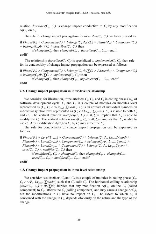
Hereafter, we show the platform architecture, which implements both GMSE model
and rule based change propagation process.
package sourceVisualizer;
import sourceVisualizer.controller.Controller;
import sourceVisualizer.model.Model;
import sourceVisualizer.view.View;
public class SourceVisualizer {
private Model model;
private View view;
private Controller control;
public SourceVisualizer() {
model = new Model();
control = new Controller();
view = new View(control);
control.setModel(model);
control.setView(view);
}
public static void main(String[] args) {
new SourceVisualizer();
}
}
Table 2. Java code slice
5. ECLIPSE Plug-in Implementation of Knowledge-Based System
We implement a semi-automated Expert System for testing and realization of
Knowledge-Based System. The fact-base of Expert System is the extracted repository
of software artefacts and their marking for change. The rules are the derived
formulations as explained above for the makeup of whole software, which are
maintained in rule-base. In this framework, we insert the artefacts to be changed and
their marked linked artefacts in knowledge base. In change propagation algorithm
(table 1), FireRule designates the set of propagation rules that can be fired.
Eclipse is a widely used open source framework for building an open
development platform comprised of extensible frameworks, tools and runtimes for
building, deploying and managing software across the lifecycle. We develop a set of
ECLIPSE plug-ins that are currently used by our team to analyze the change impact
propagation affecting a java project developed on top of ECLIPSE. The first element
Actes du XXVII° congrès INFORSID, Toulouse, mai 2009
120
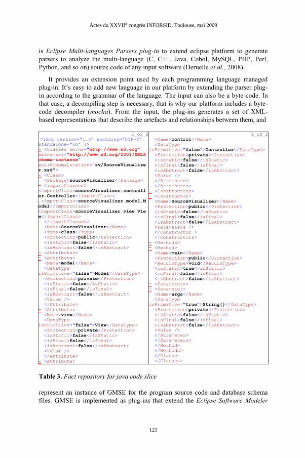
is Eclipse Multi-languages Parsers plug-in to extend eclipse platform to generate
parsers to analyze the multi-language (C, C++, Java, Cobol, MySQL, PHP, Perl,
Python, and so on) source code of any input software (Deruelle et al., 2008).
It provides an extension point used by each programming language managed
plug-in. It’s easy to add new language in our platform by extending the parser plug-
in according to the grammar of the language. The input can also be a byte-code. In
that case, a decompiling step is necessary, that is why our platform includes a byte-
code decompiler (mocha). From the input, the plug-ins generates a set of XML-
based representations that describe the artefacts and relationships between them, and
1 of 2
<?xml version="1.0" encoding="UTF-8" standalone="no" ?>
- <Classes xmlns="http://www.w3.org"
xmlns:xsi="http://www.w3.org/2001/XMLS
chema-instance"
xsi:SchemaLocation="sv/SourceVisualize
r.xsd">
- <Class>
<Package>sourceVisualizer</Package>
- <importClasses>
<importClass>sourceVisualizer.controll
er.Controller</importClass>
<importClass>sourceVisualizer.model.M
odel</importClass>
<importClass>sourceVisualizer.view.Vie
w</importClass>
</importClasses>
<Name>SourceVisualizer</Name>
<Type>class</Type>
<Protection>public</Protection>
<isStatic>false</isStatic>
<isAbstract>false</isAbstract>
- <Attributes>
- <Attribute>
<Name>model</Name>
<DataType
isPrimitive="false">Model</DataType>
<Protection>private</Protection>
<isStatic>false</isStatic>
<isFinal>false</isFinal>
<isAbstract>false</isAbstract>
<Value />
</Attribute>
- <Attribute>
<Name>view</Name>
<DataType
isPrimitive="false">View</DataType>
<Protection>private</Protection>
<isStatic>false</isStatic>
<isFinal>false</isFinal>
<isAbstract>false</isAbstract>
<Value />
</Attribute>
- <Attribute>
2 of 2
<Name>control</Name>
<DataType
isPrimitive="false">Controller</DataType>
<Protection>private</Protection>
<isStatic>false</isStatic>
<isFinal>false</isFinal>
<isAbstract>false</isAbstract>
<Value />
</Attribute>
</Attributes>
- <Constructors>
- <Constructor>
<Name>SourceVisualizer</Name>
<Protection>public</Protection>
<isStatic>false</isStatic>
<isFinal>false</isFinal>
<isAbstract>false</isAbstract>
<Parameters />
</Constructor >
</Constructors>
- <Methods>
- <Method>
<Name>main</Name>
<Protection>public</Protection>
<ReturnType>void</ReturnType>
<isStatic>true</isStatic>
<isFinal>false</isFinal>
<isAbstract>false</isAbstract>
- <Parameters>
- <Parameter>
<Name>args</Name>
<DataType
isPrimitive="true">String[]</DataType>
<Protection>private</Protection>
<isStatic>false</isStatic>
<isFinal>false</isFinal>
<isAbstract>false</isAbstract>
<Value />
</Parameter>
</Parameters>
</Method>
</Methods>
</Class>
</Classes>
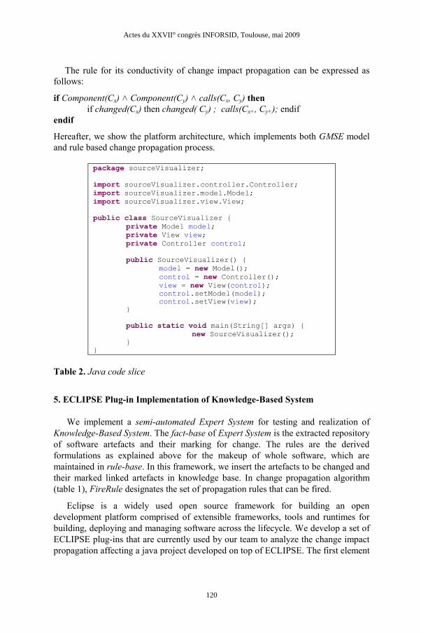
Table 3. Fact repository for java code slice
represent an instance of GMSE for the program source code and database schema
files. GMSE is implemented as plug-ins that extend the Eclipse Software Modeler
Actes du XXVII° congrès INFORSID, Toulouse, mai 2009
121
Plug-in. This provides basic services for the graph creation and transformation based
on the XML-based representation of affected software artefacts, as a result of change
incorporation process. A graph contains nodes and links representing software
artefacts and relationships defined in the implemented models plug-ins. The Eclipse
Graph Visualizer Plug-in shows the resulting graph and allows to perform changes
on the graph. The Eclipse Change Propagation Engine Plug-in is based on an
Engine Rules (JBOSS Rules) and propagates a change performed on an artefact to
the belonged artefacts. The propagation is based on change propagation rules, which
are fired by inserting facts, provided by the facts builder. The facts builder inserts
facts, that represents the software artefacts and the relationships stored in the
repository. A change propagation rule is a Production Rule which is a two-part
structure using First Order Logic for knowledge representation. The process of
matching the new or existing facts against Production Rules is based on the Rete
algorithm. An example java code slice (table 2) is used as input to our eclipse based
platform; we get the intermediate repository of facts as shown in table 3. This output
confines the results as per our GMSE facts schema for software artefacts in code
phase, given in Annex to this article.
6. Conclusion
We proposed an integrated model aiming at a better change management of
software artefacts evolution throughout a Knowledge-Based System. The
implemented system permits to visualize software artefacts of a development phase
in their different granular levels. Such a visualization eases greatly the task of
analyzing and understanding of change impact propagation. It uses the specific
potential of each individual relationship type occurrence related to change impact
conductance between linked software artefacts at their different granular levels. The
identification of change impact propagation has been there described by using a rule
based approach in which a set of expert rules is defined, for better management of
software evolution. These rules are activated in respect with the content of fact-base
extracted from the software artefacts modeled according to GMSE. The possible
flow of change impact propagation can be therefore traced on the basis of change
impact conductance as expressed by a subset of rules corresponding to the occurred
relationship type between modified components.
The KBSSE is able to define the extent to which a software artefact is affected by
a change and the propagation of that change on the other linked artefacts. It
iteratively identifies this extent on all affected artefacts and constructs the path of
change impact flow. The analysis of change impact conductivity uses different rules
describing the possible propagation of operated change from the directly concerned
software artefact to all other possible artefacts of the whole software. The flow of
propagation identification is based on the role of each particular relationship type
occurring between initially (or subsequently) affected components. The definition of
expert rules describing the different possible steps of change propagation between
Actes du XXVII° congrès INFORSID, Toulouse, mai 2009
122

software artefacts constitutes a major mechanism we have used towards a better
control of change impact propagation.
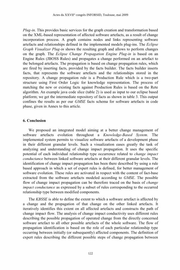
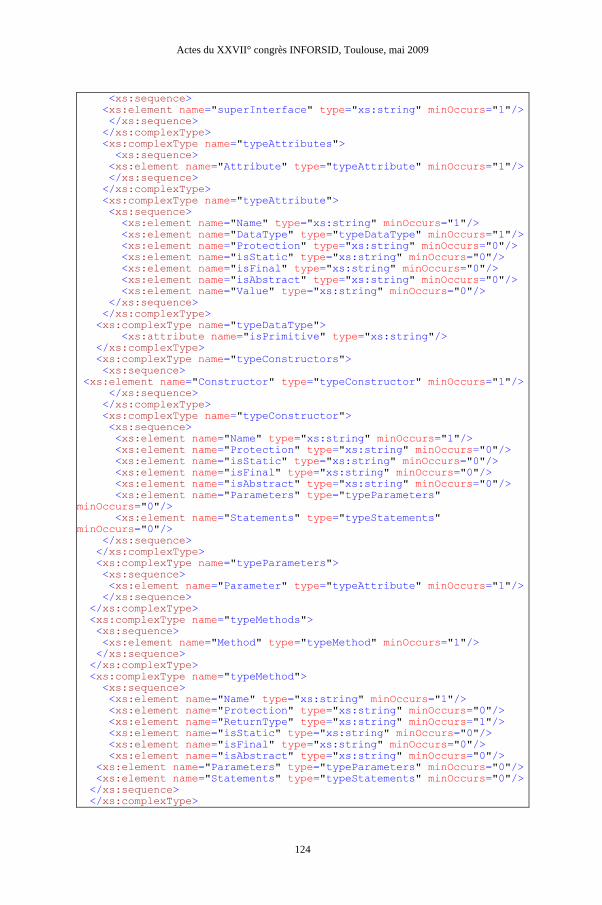
7. Annex: XML Schema Definition for software artefacts in code phase
<?xml version="1.0" encoding="UTF-8"?>
<xs:schema xmlns:xs="http://www.w3.org/2001/XMLSchema"
targetNamespace="http://www.example.org/source_visualizer"
xmlns="http://www.example.org/source_visualizer"
elementFormDefault="qualified">
<!-- @author <a href="mailto:[email protected]">Adeel Ahmad</a>
-->
<!-- @created May 30, 2008 -->
<!-- @last_Modified Feb 08, 2009 -->
<xs:element name="Classes">
<xs:complexType>
<xs:sequence>
<xs:element name="Class" type="typeClass" minOccurs="1" />
</xs:sequence>
</xs:complexType>
</xs:element>
<xs:complexType name="typeClass">
<xs:sequence>
<xs:element name="Package" type="xs:string" minOccurs="0"/>
<xs:element name="importClasses" type="typeImportClasses"
minOccurs="0"/>
<xs:element name="Name" type="xs:string" minOccurs="1"/>
<xs:element name="Type" type="xs:string" minOccurs="1"/>
<xs:element name="Protection" type="xs:string" minOccurs="1"/>
<xs:element name="isStatic" type="xs:string" minOccurs="1"/>
<xs:element name="isAbstract" type="xs:string" minOccurs="1"/>
<xs:element name="superClasses" type="typeSuperClasses"
minOccurs="0"/>
<xs:element name="superInterfaces" type="typeSuperInterfaces"
minOccurs="0"/>
<xs:element name="Attributes" type="typeAttributes"
minOccurs="0"/>
<xs:element name="Constructors" type="typeConstructors"
minOccurs="0"/>
<xs:element name="Methods" type="typeMethods" minOccurs="0"/>
<xs:element name="innerClasses" type="typeInnerClasses"
minOccurs="0"/>
<xs:element name="associateClasses" type="typeAssociateClasses"
minOccurs="0"/>
</xs:sequence>
</xs:complexType>
<xs:complexType name="typeImportClasses">
<xs:sequence>
<xs:element name="importClass" type="xs:string" minOccurs="1"/>
</xs:sequence>
</xs:complexType>
<xs:complexType name="typeSuperClasses">
<xs:sequence>
<xs:element name="superClass" type="xs:string" minOccurs="1"/>
</xs:sequence>
</xs:complexType>
<xs:complexType name="typeSuperInterfaces">
Actes du XXVII° congrès INFORSID, Toulouse, mai 2009
123
<xs:sequence>
<xs:element name="superInterface" type="xs:string" minOccurs="1"/>
</xs:sequence>
</xs:complexType>
<xs:complexType name="typeAttributes">
<xs:sequence>
<xs:element name="Attribute" type="typeAttribute" minOccurs="1"/>
</xs:sequence>
</xs:complexType>
<xs:complexType name="typeAttribute">
<xs:sequence>
<xs:element name="Name" type="xs:string" minOccurs="1"/>
<xs:element name="DataType" type="typeDataType" minOccurs="1"/>
<xs:element name="Protection" type="xs:string" minOccurs="0"/>
<xs:element name="isStatic" type="xs:string" minOccurs="0"/>
<xs:element name="isFinal" type="xs:string" minOccurs="0"/>
<xs:element name="isAbstract" type="xs:string" minOccurs="0"/>
<xs:element name="Value" type="xs:string" minOccurs="0"/>
</xs:sequence>
</xs:complexType>
<xs:complexType name="typeDataType">
<xs:attribute name="isPrimitive" type="xs:string"/>
</xs:complexType>
<xs:complexType name="typeConstructors">
<xs:sequence>
<xs:element name="Constructor" type="typeConstructor" minOccurs="1"/>
</xs:sequence>
</xs:complexType>
<xs:complexType name="typeConstructor">
<xs:sequence>
<xs:element name="Name" type="xs:string" minOccurs="1"/>
<xs:element name="Protection" type="xs:string" minOccurs="0"/>
<xs:element name="isStatic" type="xs:string" minOccurs="0"/>
<xs:element name="isFinal" type="xs:string" minOccurs="0"/>
<xs:element name="isAbstract" type="xs:string" minOccurs="0"/>
<xs:element name="Parameters" type="typeParameters"
minOccurs="0"/>
<xs:element name="Statements" type="typeStatements"
minOccurs="0"/>
</xs:sequence>
</xs:complexType>
<xs:complexType name="typeParameters">
<xs:sequence>
<xs:element name="Parameter" type="typeAttribute" minOccurs="1"/>
</xs:sequence>
</xs:complexType>
<xs:complexType name="typeMethods">
<xs:sequence>
<xs:element name="Method" type="typeMethod" minOccurs="1"/>
</xs:sequence>
</xs:complexType>
<xs:complexType name="typeMethod">
<xs:sequence>
<xs:element name="Name" type="xs:string" minOccurs="1"/>
<xs:element name="Protection" type="xs:string" minOccurs="0"/>
<xs:element name="ReturnType" type="xs:string" minOccurs="1"/>
<xs:element name="isStatic" type="xs:string" minOccurs="0"/>
<xs:element name="isFinal" type="xs:string" minOccurs="0"/>
<xs:element name="isAbstract" type="xs:string" minOccurs="0"/>
<xs:element name="Parameters" type="typeParameters" minOccurs="0"/>
<xs:element name="Statements" type="typeStatements" minOccurs="0"/>
</xs:sequence>
</xs:complexType>
Actes du XXVII° congrès INFORSID, Toulouse, mai 2009
124
<xs:complexType name="typeStatements">
<xs:sequence>
<xs:element name="Statement" type="typeStatement" minOccurs="1"/>
</xs:sequence>
</xs:complexType>
<xs:complexType name="typeStatement">
<xs:sequence>
<xs:element name="reserveWords" type="typeReserveWords"
minOccurs="0"/>
<xs:element name="DataMembers" type="typeAttributes" minOccurs="0"/>
<xs:element name="Terminator" type="xs:string" minOccurs="1"/>
</xs:sequence>
</xs:complexType>
<xs:complexType name="typeReserveWords">
<xs:sequence>
<xs:element name="reserveWord" type="typeReserveWord"
minOccurs="1"/>
</xs:sequence>
</xs:complexType>
<xs:complexType name="typeReserveWord">
<xs:sequence>
<xs:element name="Operation" type="xs:string" minOccurs="1"/>
<xs:element name="operatorSymbol" type="xs:string"
minOccurs="0"/>
</xs:sequence>
</xs:complexType>
<xs:complexType name="typeInnerClasses">
<xs:sequence>
<xs:element name="innerClass" type="typeInnerClass" minOccurs="1"/>
</xs:sequence>
</xs:complexType>
<xs:complexType name="typeInnerClass" >
<xs:complexContent>
<xs:extension base="typeClass">
<xs:sequence>
<xs:element name="outerClass" type="xs:string" minOccurs="0"/>
</xs:sequence>
</xs:extension>
</xs:complexContent>
</xs:complexType>
<xs:complexType name="typeAssociateClasses">
<xs:sequence>
<xs:element name="associateClass" type="typeAssociateClass"
minOccurs="1"/>
</xs:sequence>
</xs:complexType>
<xs:complexType name="typeAssociateClass">
<xs:complexContent>
<xs:extension base="typeClass">
<xs:sequence>
<xs:element name="publicClass" type="xs:string" minOccurs="0"/>
</xs:sequence>
</xs:extension>
</xs:complexContent>
</xs:complexType>
</xs:schema>
Actes du XXVII° congrès INFORSID, Toulouse, mai 2009
125

8. References
Ahmad A., Basson H., and Bouneffa M., “Software Evolution Control: Towards a better
identification of change impact propagation”, in 4th IEEE International Conference on
Emerging Technologies, Rawalpindi, Pakistan, Oct. 2008a, ISBN 978-1-4244-2210-4.
Ahmad A., Basson H., Deruelle L., and Bouneffa M., “Towards a better control of Change
Impact Propagation”, in 12th IEEE International Multitopic Conference (INMIC’08),
Karachi, Pakistan, 23-24 Dec. 2008b, ISBN 978-1-4244-2823-6.
D’Ambros M., Lanza M., “Reverse Engineering with Logical Coupling”, in 13th Working
Conference on Reverse Engineering, IEEE Computer Society, 2006, pp. 189–198.
Deruelle L., Basson H., “An Eclipse Platform for Analysis and Manipulation of Distributed
Multi-Language Software”, in ISCA 21st International Conference on Computer
Applications in Industry and Eng. Honolulu, Hawaii, USA, Nov. 2008 ISBN 978-1-
880843-65-9.
Deruelle L., Bouneffa M., Melab N., and Basson H., “Analysis and Manipulation of
Distributed Multi-Language Software Code”, in IEEE Intl. Workshop on Source Code
Analysis and Manipulation (IEEE-SCAM'01), Florence, Italy, Nov 2001.
Fowler M., Refactoring: Improving the Design of Existing Code, Addison Wesley Object
Technology Series, July 1999 ISBN 0201485672
Gall H., Jazayeri M., Klösh R., and Trausmuth G., “Software evolution observations based on
product release history”, in International Conference on Software Maintenance, Los
Alamitos CA, 1997, pp. 160-166.
Huzefa K., Shenaaz Y., and Jonathan M. I., “Mining Sequences of Changed-files from
Version Histories”, in International Workshop on Mining Software Repositories, 2006,
pp. 47-53.
Lungu M., Lanza M., Girba T., and Heeck R., “Reverse Engineering Super-Repositories”, in
14th Working Conference on Reverse Engineering (WCRE’07), IEEE Computer Society,
2007, pp. 120 - 129.
Melab N., Deruelle L., Bouneffa M., and Basson H., “Towards a Changeability Assessment
of Distributed Multi-language Software Code”, in 7th IEEE Intl. Workshop on Empirical
Studies of Software Maintenance (WESS'01), Florence, Italy, Nov. 9, 2001.
Pressman R. S., Software Engineering: A Practitioner's Approach, 7th edition, Mc Graw-Hill
Higher Education, Jan. 2009, ISBN 0073375977
Robbes R., “Mining a Change-Based software Repository”, in Fourth International
Workshop on Mining Software Repositories, 2007.
Rumbaugh J., Jacobson I., and Booch G., The Unified Modeling Language Reference
Manual, 2nd edition, The Addison-Wesley Professional, May 2005 ISBN 0321267974.
Rysselberghe V. F. and Demeyer S., “Studying software evolution information by visualizing
the change history”, in 20th IEEE International Conference on Software Maintenance,
Los Alamitos CA, 11-14 Sep. 2004, pp. 328-337.
Actes du XXVII° congrès INFORSID, Toulouse, mai 2009
126