A kinematic FE limit analysis model for thick English bond masonry walls
30
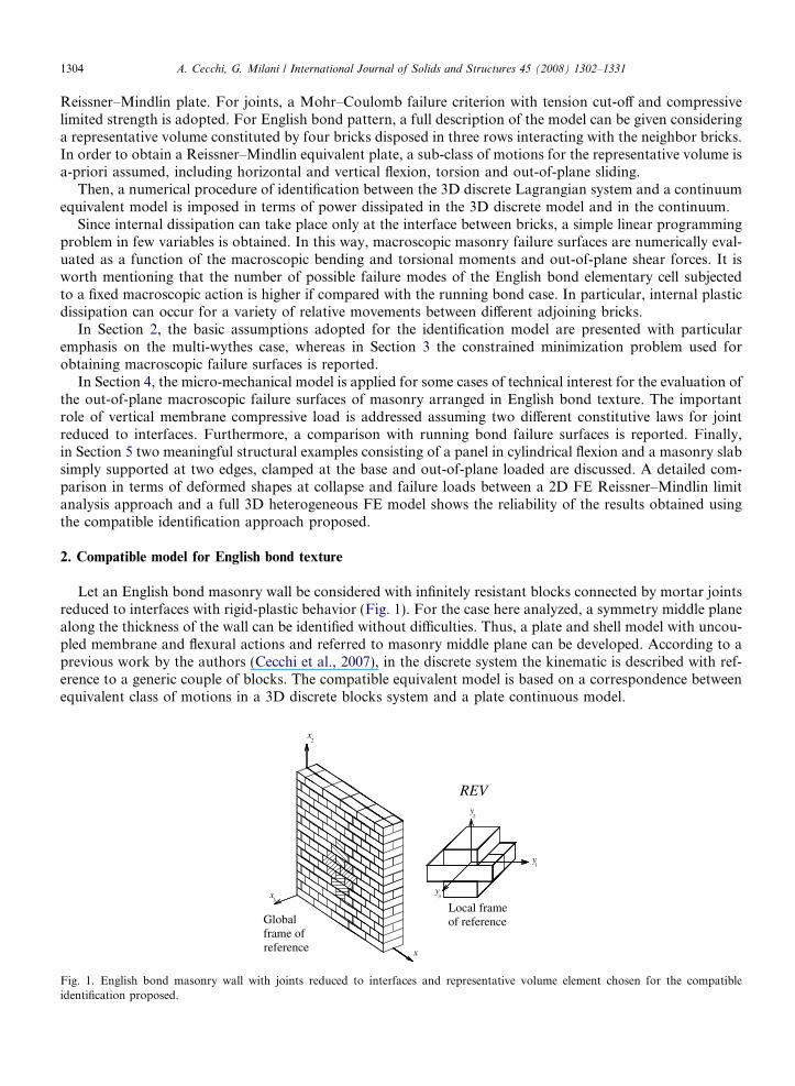
A kinematic FE limit analysis model for thick English bond masonry walls A. Cecchi a , G. Milani b, * a IUAV University of Venice Dorsoduro 2206, ex convento Terese, 30123 Venezia, Italy b Department of Engineering, University of Ferrara, Via Saragat 1, 44100 Ferrara, Italy Received 30 April 2007; received in revised form 27 August 2007 Available online 1 October 2007 Abstract Two-wythes masonry walls arranged in English bond texture were often used in the past as bearing panels in seismic area. On the other hand, earthquake surveys have demonstrated that masonry strength under horizontal actions is usually insufficient, causing premature collapses of masonry buildings, often ascribed to out-of-plane actions. Furthermore, many codes of practice impose for new brickwork walls a minimal slenderness, which for instance is fixed by the Italian O.P.C.M. 3431 equal to 12 for artificial bricks and 10 for natural blocks masonry. For the above reasons, the analysis at failure of English bond brickwork walls under out-of-plane actions is a topic that deserves consideration, despite the fact that almost the totality of the studies of masonry at failure is devoted to running bond arrangements. Furthermore, it must be noted that an approach based on the analysis of running bond texture – in comparison with English bond pattern – is not suitable for the investigation of the behavior of bearing panels. In this framework, in the present paper, a Reissner–Mindlin kinematic limit analysis approach is presented for the der- ivation of the macroscopic failure surfaces of two-wythes masonry arranged in English bond texture. In particular, the behavior of a 3D system constituted by infinitely resistant bricks connected by joints reduced to interfaces with frictional behavior and limited tensile/compressive strength is identified with a 2D Reissner–Mindlin plate. In this way, assuming both an associated flow rule for the constituent materials and a finite subclass of possible deformation modes, an upper bound approximation of macroscopic English bond masonry failure surfaces is obtained as a function of macroscopic bending moments, torsion and shear forces. Several examples of technical relevance are treated both at a cell level and at a structural level, addressing the differences in terms of collapse loads and failure surfaces due to different textures and constituent laws for joints. Finally, two mean- ingful structural examples consisting of a panel in cylindrical flexion and a masonry slab constrained at three edges and out-of-plane loaded are discussed. A detailed comparison in terms of deformed shapes at collapse and failure loads between a 2D FE Reissner–Mindlin limit analysis approach and a full 3D heterogeneous FE model shows the reliability of the results obtained using the kinematic identification approach proposed. Ó 2007 Elsevier Ltd. All rights reserved. Keywords: Masonry; Reissner–Mindlin plates; English bond; Limit analysis; Out-of-plane loads 0020-7683/$ - see front matter Ó 2007 Elsevier Ltd. All rights reserved. doi:10.1016/j.ijsolstr.2007.09.019 * Corresponding author. Tel.: +39 0532 974911; fax: +39 0532 974870. E-mail address: [email protected] (G. Milani). Available online at www.sciencedirect.com International Journal of Solids and Structures 45 (2008) 1302–1331 www.elsevier.com/locate/ijsolstr
Transcript of A kinematic FE limit analysis model for thick English bond masonry walls
Available online at www.sciencedirect.com
International Journal of Solids and Structures 45 (2008) 1302–1331
www.elsevier.com/locate/ijsolstr
A kinematic FE limit analysis model for thickEnglish bond masonry walls
A. Cecchi a, G. Milani b,*
a IUAV University of Venice Dorsoduro 2206, ex convento Terese, 30123 Venezia, Italyb Department of Engineering, University of Ferrara, Via Saragat 1, 44100 Ferrara, Italy
Received 30 April 2007; received in revised form 27 August 2007Available online 1 October 2007
Abstract
Two-wythes masonry walls arranged in English bond texture were often used in the past as bearing panels in seismicarea. On the other hand, earthquake surveys have demonstrated that masonry strength under horizontal actions is usuallyinsufficient, causing premature collapses of masonry buildings, often ascribed to out-of-plane actions. Furthermore, manycodes of practice impose for new brickwork walls a minimal slenderness, which for instance is fixed by the Italian O.P.C.M.3431 equal to 12 for artificial bricks and 10 for natural blocks masonry.
For the above reasons, the analysis at failure of English bond brickwork walls under out-of-plane actions is a topic thatdeserves consideration, despite the fact that almost the totality of the studies of masonry at failure is devoted to runningbond arrangements. Furthermore, it must be noted that an approach based on the analysis of running bond texture – incomparison with English bond pattern – is not suitable for the investigation of the behavior of bearing panels.
In this framework, in the present paper, a Reissner–Mindlin kinematic limit analysis approach is presented for the der-ivation of the macroscopic failure surfaces of two-wythes masonry arranged in English bond texture. In particular, thebehavior of a 3D system constituted by infinitely resistant bricks connected by joints reduced to interfaces with frictionalbehavior and limited tensile/compressive strength is identified with a 2D Reissner–Mindlin plate. In this way, assumingboth an associated flow rule for the constituent materials and a finite subclass of possible deformation modes, an upperbound approximation of macroscopic English bond masonry failure surfaces is obtained as a function of macroscopicbending moments, torsion and shear forces.
Several examples of technical relevance are treated both at a cell level and at a structural level, addressing the differencesin terms of collapse loads and failure surfaces due to different textures and constituent laws for joints. Finally, two mean-ingful structural examples consisting of a panel in cylindrical flexion and a masonry slab constrained at three edges andout-of-plane loaded are discussed. A detailed comparison in terms of deformed shapes at collapse and failure loadsbetween a 2D FE Reissner–Mindlin limit analysis approach and a full 3D heterogeneous FE model shows the reliabilityof the results obtained using the kinematic identification approach proposed.� 2007 Elsevier Ltd. All rights reserved.
Keywords: Masonry; Reissner–Mindlin plates; English bond; Limit analysis; Out-of-plane loads
0020-7683/$ - see front matter � 2007 Elsevier Ltd. All rights reserved.
doi:10.1016/j.ijsolstr.2007.09.019
* Corresponding author. Tel.: +39 0532 974911; fax: +39 0532 974870.E-mail address: [email protected] (G. Milani).

A. Cecchi, G. Milani / International Journal of Solids and Structures 45 (2008) 1302–1331 1303
1. Introduction
Consolidated rules of thumbs used for centuries by European technicians suggest to prevent premature lossof equilibrium of masonry elements subjected to horizontal loads by reducing their slenderness. Following thisprinciple, many codes of practice impose for new brickwork walls a minimal height/thickness ratio, which isfor instance fixed by the Italian O.P.C.M. 3431 (2005) equal to 12 for artificial bricks and 10 for natural blocksmasonry.
As a consequence, existing and new masonry structures in European seismic areas can be build in multi-wythes thickness arrangements, being English and Flemish bond two of the most diffused patterns.
On the other hand, the inadequate resistance of brickwork under out-of-plane loads is well known. Suchactions are usually related to seismic events and represent a primary cause of failure in different typologiesof masonry, especially for historical buildings (see for instance Spence and Coburn, 1992). Related to thisproblem, another relevant aspect that should be considered is the important role held by vertical compressivemembrane actions on out-of-plane strength. As a rule, in fact, vertical loads (either self weight and permanentloads) are not negligible and increase both the ultimate out-of-plane strength and the ductility of masonry,bringing additional complexity to the structural analyses.
Despite the considerable efforts made in the last decade for the analysis at collapse of masonry elementsout-of-plane loaded, almost the totality of these studies is devoted to running bond textures. On the contrary,there is still a lack of knowledge concerning multi-wythes thickness walls, probably due to complexity of pos-sible numerical models, closely related to the high number of variables involved when standard heterogeneousFE non-linear analyses are performed. Moreover, other two important aspects of masonry at failure that pre-clude the utilization of standard FE codes is the anisotropy (Milani et al., 2006a), closely related to the con-stituent materials (mortar and bricks) and the bond pattern, and the limited compressive strength, which isindependent from shear strength, as demonstrated experimentally by Page (1981).
For the above reasons, the analysis at failure of English bond brickwork walls subjected to out-of-planeactions is a topic that deserves consideration. In particular, a model based on a simplified kinematically admis-sible homogenization approach and limit analysis seems particularly attractive, since the actual arrangementof bricks and mortar can be considered only at a cell level.
Furthermore, a limit analysis approach requires only a reduced number of material parameters and is ableto provide as output information limit multipliers of loads, failure mechanisms and, at least on critical sec-tions, the stress distribution at collapse (see Sutcliffe et al., 2001).
In this framework, in the present paper, a kinematic limit analysis approach in which (�a) bricks are supposedinfinitely resistant and (�b) joints are reduced to interfaces, is used in order to have a realistic prediction of theactual behavior at failure of panels out-of-plane loaded. It is worth noting that models based on the homogeni-zation theory have been presented under the same hypotheses by de Buhan and de Felice (1997) for in-planeloaded walls and by Cecchi et al. (2007) for out-of-plane loaded running bond plates. In both cases, an associatedflow rule for joints was adopted, despite the fact that frictional phenomena may require the adoption ofnon-associated plasticity for the constituent materials (Ferris and Tin-Loi, 2001; Orduna and Lourenco, 2005).
Nevertheless, at present, we have not at disposal theorems regarding homogenization of rigid plastic mate-rials with non-associated flow rule, even if calculations could be carried out, given a friction and a dilationangles for mortar, with an ‘‘effective’’ friction and associated flow rules (Drescher and Detournay, 1993).
On the other hand, the adoption of non-associated plasticity implies the lack of the uniqueness of the solu-tion, i.e. that a multiplicity of solutions can exist for these limit analysis problems (see Begg and Fishwick,1995). On the contrary, when associated plasticity is adopted for the constituent materials, homogenizationtheory can be used in combination with limit analysis (as suggested by Suquet, 1983) for the evaluation ofthe macroscopic strength domains and simple linear programming problems (easily manageable by meansof standard packages) are obtained.
Following the general procedure adopted by the authors for running bond textures (Cecchi et al., 2007), inthis paper a simple micro-mechanical model for the kinematic limit analysis of English bond walls out-of-plane loaded under Reissner–Mindlin plate hypotheses is presented.
In analogy to what proposed for running bond textures, a 3D system of infinitely resistant bricks interact-ing through mortar joints reduced to interfaces is identified with a rigid-plastic homogeneous and anisotropic
1304 A. Cecchi, G. Milani / International Journal of Solids and Structures 45 (2008) 1302–1331
Reissner–Mindlin plate. For joints, a Mohr–Coulomb failure criterion with tension cut-off and compressivelimited strength is adopted. For English bond pattern, a full description of the model can be given consideringa representative volume constituted by four bricks disposed in three rows interacting with the neighbor bricks.In order to obtain a Reissner–Mindlin equivalent plate, a sub-class of motions for the representative volume isa-priori assumed, including horizontal and vertical flexion, torsion and out-of-plane sliding.
Then, a numerical procedure of identification between the 3D discrete Lagrangian system and a continuumequivalent model is imposed in terms of power dissipated in the 3D discrete model and in the continuum.
Since internal dissipation can take place only at the interface between bricks, a simple linear programmingproblem in few variables is obtained. In this way, macroscopic masonry failure surfaces are numerically eval-uated as a function of the macroscopic bending and torsional moments and out-of-plane shear forces. It isworth mentioning that the number of possible failure modes of the English bond elementary cell subjectedto a fixed macroscopic action is higher if compared with the running bond case. In particular, internal plasticdissipation can occur for a variety of relative movements between different adjoining bricks.
In Section 2, the basic assumptions adopted for the identification model are presented with particularemphasis on the multi-wythes case, whereas in Section 3 the constrained minimization problem used forobtaining macroscopic failure surfaces is reported.
In Section 4, the micro-mechanical model is applied for some cases of technical interest for the evaluation ofthe out-of-plane macroscopic failure surfaces of masonry arranged in English bond texture. The importantrole of vertical membrane compressive load is addressed assuming two different constitutive laws for jointreduced to interfaces. Furthermore, a comparison with running bond failure surfaces is reported. Finally,in Section 5 two meaningful structural examples consisting of a panel in cylindrical flexion and a masonry slabsimply supported at two edges, clamped at the base and out-of-plane loaded are discussed. A detailed com-parison in terms of deformed shapes at collapse and failure loads between a 2D FE Reissner–Mindlin limitanalysis approach and a full 3D heterogeneous FE model shows the reliability of the results obtained usingthe compatible identification approach proposed.
2. Compatible model for English bond texture
Let an English bond masonry wall be considered with infinitely resistant blocks connected by mortar jointsreduced to interfaces with rigid-plastic behavior (Fig. 1). For the case here analyzed, a symmetry middle planealong the thickness of the wall can be identified without difficulties. Thus, a plate and shell model with uncou-pled membrane and flexural actions and referred to masonry middle plane can be developed. According to aprevious work by the authors (Cecchi et al., 2007), in the discrete system the kinematic is described with ref-erence to a generic couple of blocks. The compatible equivalent model is based on a correspondence betweenequivalent class of motions in a 3D discrete blocks system and a plate continuous model.
y
Global frame of reference x
3x 3
y
Local frame of reference
2
y
x2
REV
1
Fig. 1. English bond masonry wall with joints reduced to interfaces and representative volume element chosen for the compatibleidentification proposed.
A. Cecchi, G. Milani / International Journal of Solids and Structures 45 (2008) 1302–1331 1305
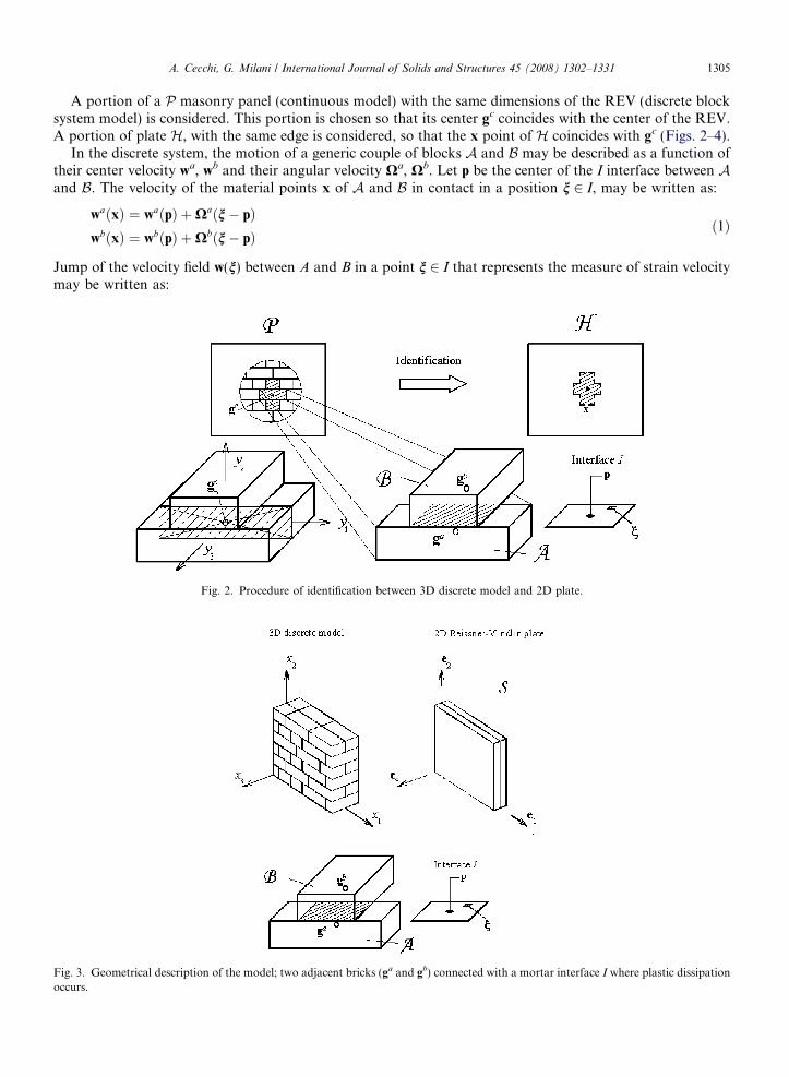
A portion of a P masonry panel (continuous model) with the same dimensions of the REV (discrete blocksystem model) is considered. This portion is chosen so that its center gc coincides with the center of the REV.A portion of plate H, with the same edge is considered, so that the x point of H coincides with gc (Figs. 2–4).
In the discrete system, the motion of a generic couple of blocks A and B may be described as a function oftheir center velocity wa, wb and their angular velocity Xa, Xb. Let p be the center of the I interface between Aand B. The velocity of the material points x of A and B in contact in a position n 2 I, may be written as:
Fig. 3.occurs
waðxÞ ¼ waðpÞ þXaðn� pÞwbðxÞ ¼ wbðpÞ þXbðn� pÞ
ð1Þ
Jump of the velocity field w(n) between A and B in a point n 2 I that represents the measure of strain velocitymay be written as:
Fig. 2. Procedure of identification between 3D discrete model and 2D plate.
Geometrical description of the model; two adjacent bricks (ga and gb) connected with a mortar interface I where plastic dissipation.

Bi, j, k+1
2
2
y3
3
y
y
y
y y y
I
I -1, -1, 0
1
3y 1, -1, 0
1
I
II
I
y3 -1, -1, -1
-1, -1, 1
1, -1, -1
1, -1, 1
1
1, 0, -1
I
-1, 1, 1II
I
0, -1, -1I
I3
-1, 1, 0
1, 1, 0
y2
y1
y0, -1, 1
1y
I
I
1, 0, 1I
1, 1, 1
3
-1, 1, -1
y2
y
y1
1, 1, -1
0, 1, 1
0, 1, -1
I
I
0, 0, 0I
y2
i, j-1, kB
Bi, j, k-1
I
0,-2, 1
0,-2,-1I
I3y
y2
1y
-1, 0, 1I
Bi, j+1, k
0, 2, 1I0, 2,-1I
1
y3
y2
y
I-1, 0, -1
y2
Fig. 4. Mortar interfaces definition.
1306 A. Cecchi, G. Milani / International Journal of Solids and Structures 45 (2008) 1302–1331
bwðnÞc ¼ wbðnÞ � waðnÞ ¼ wbðpÞ � waðpÞ þXbðn� pÞ �Xaðn� pÞ ¼ wp þXpðn� pÞ ð2Þ
where wp = wb(p) � wa(p) and Xp = Xb � Xa.Side by side for the panel, a 2D plate model is introduced independently from the discrete 3D model. The
plate is identified by its middle plane S of normal e3 (Fig. 3).In a parallel manner, respect to the discrete model, in a plate continuum model the generic motion is
described by the following fields:
wðxÞXðxÞ
ð3Þ
where w(x) and X(x) are the velocity vector and angular velocity tensor of the material point x, respectively.Hence it is possible to assign a correspondence between a class of regular motions in P and H. The velocity
and angular velocity of the center of the brick A and B in the discrete system and velocity and angular velocityof the center of the REV in the continuum model are equal:
waðxÞ ¼ wðxÞ þ grad wðxÞðga � xÞXaðxÞ ¼ XðxÞ þ gradXðxÞðga � xÞ
ð4Þ
and
wbðxÞ ¼ wðxÞ þ grad wðxÞðgb � xÞXbðxÞ ¼ XðxÞ þ gradXðxÞðgb � xÞ
ð5Þ

A. Cecchi, G. Milani / International Journal of Solids and Structures 45 (2008) 1302–1331 1307
where ga and gb are the center of the A;B 2 P generic couple of bricks and a first order Taylor approximation(first order identification) in the velocity and angular velocity is used In the discrete system, the contact forcesbetween blocks A and B are ta(n) and tb(n) for n 2 I. Equilibrium condition requires that ta(n) = �tb(n). Hence,�set tb(n) = t (n), the power dissipated at the interface is:
p ¼Z
ItaðnÞ � waðnÞ þ tbðnÞ � wbðnÞ ¼
ZI
tðnÞ � ½wbðnÞ � waðnÞ� ¼ tp � wp þXp �Z
Iskw t� ðn� pÞ ð6Þ
Set tp ¼R
I tðnÞ and Mp ¼ 2R
I skw t� ðn� pÞ, Eq. (6) can be written as follows:
pp ¼ tp � wp þ1
2Mp �Xp ð7Þ
Let us define the vector tp as tp ¼ �tp þ t3p ¼ t1p t2p 0½ �T þ 0 0 t3p½ �T where �tp denotes the projection on Sof tp and t3p is the component orthogonal to S of tp. Taking into consideration correspondent motion tests,from Eqs. (4) and (5), Eq. (7) may be written as:
tp � wp ¼ �tp � ðgb � gaÞ � ðgrad �wÞ þ t3pðgb � gaÞ � ðgradw3 þXe3Þ ð8Þþ t3p½ðp� gaÞ � ðga � xÞ � ðp� gbÞ � ðgb � xÞ� � ðgradXe3Þ
1
2Mp �Xp ¼
ZIðtðnÞ � dp � dp � tðnÞÞ � ðgradXÞðgb � gaÞ
¼ 1
2
ZIðd3p�tðnÞ � t3ðnÞ�dpÞ � ðgb � gaÞðgradXe3Þ ð9Þ
where the distance vector dp can be written as dp = n � p. According to the previous notation dp may bedecomposed as dp ¼ �dp � d3p
In the same manner, for the continuum, set N membrane and shear actions and M bending and torsion.Themechanical power evaluated on S may be written as:
p ¼ N � symðgrad wÞ þ ðNe3 � e3Þ �WþM � symðgradXe3Þ ð10Þ
where grad represents the gradient operator on S. Total internal power dissipated can be evaluated as the sumof power dissipated by membrane actions, plate shear actions, bending and torsional moments. In particular,by indicating with an upper line the projection on S, the previous equation becomes:
p ¼ N � symðgrad �wÞ þ T � ðgradw3 þXe3Þ þM � symðgradXe3Þ ð11Þ
In what follows we assume:
– symðgrad �wÞ ¼ _E, where _E is the in-plane membrane strain rate tensor;– symðgradXe3Þ ¼ _v, where _v is the curvature rate tensor ð _vab ¼ 1=2ðxa;b þ xb;aÞ with a,b = 1,2);– gradw3 þXe3 ¼ _c ¼ _c13 _c23½ �T, where _c is the shear strain rate vector.
Furthermore, N represents the membrane actions tensor, Ne3 = T represents the shear actions vector andM represents the bending moments and torsion tensor. It must be noted that the angular velocity tensor X(x)in the case of a plate model is: xa with the Greek index a = 1,2. In fact, as well known x3 component is equalto zero in the case of plate model.
At this stage, for a chosen REV and a given class of regular motions, we impose that the mechanical powerdissipated by the contact actions on P and H coincides. Under these assumptions, the membrane and momenttensors N and M, as well as plate shear vector T(T = Ne3) may be expressed as a function of the vector tp, i.e.of the measure of the stress in the micro-mechanical model.
1308 A. Cecchi, G. Milani / International Journal of Solids and Structures 45 (2008) 1302–1331
N ¼ 1
2A
Xn
sym�tp � ðgb � gaÞ
T ¼ 1
2A
Xn
t3pðgb � gaÞ
M ¼ 1
2A
Xn
t3p sym½ðp� gaÞ � ðga � xÞ � ðp� gbÞ � ðgb � xÞ�" #
þX
n
ZI
sym½d3p�tðnÞ � t3ðnÞ�dp� � ðgb � gaÞ�
ð12Þ
where A is the area of the chosen REV and the symbolP
indicates a summation extended to all the interfacesto which the chosen REV is in contact. It must be noted that the part of p associated to skw{gradW} and toskw{grad We3} is not taken into account. In fact, in the adopted plate model these kinematic fields character-ize neutral (rigid) motions.
The 1/2 coefficient which appears in the above expressions for N, T and M is relative only to the externalsinterfaces of the REV – the power dissipated at the interface between two REVs involves both REVs – while inthe case of interfaces internal to the REV the coefficient for N, T and M is 1.
2.1. The multi-wythes masonry case
In this section, the derivation of a plate model for English bond masonry is presented as a simple applica-tion of the proposed theory. In the follows the procedure adopted by the authors (Cecchi et al., 2007) for thedefinition of 3D discrete model is used.
It is worth noting that the procedure followed in this paper is not based on rigorous homogenization the-ory, but it represents a straightforward approach of identification between 3D discrete model and 2D Reiss-ner–Mindlin plate. The application of classic homogenization is avoided in order to put at disposal topractitioners a technically simple kinematically admissible model. The a-priori assumption of a sub-class ofregular motions in the RVE, representing a number of most probable elementary failure mechanisms whichcan occur in practice, simplifies the formulation to a great extent, giving the possibility of symbolically handlethe optimization problem at a cell level. From a theoretical point of view, such macroscopic motions have tobe homogeneous. In this way, the model obtained is compatible (but not necessarily equilibrated) and theintroduction of periodic velocity fields, required by rigorous homogenization theory, can be circum-vented.Therefore, even if the simple model proposed is far to be rigorous, it can be profitably used by prac-titioners for structural analyses at collapse.
From the above considerations, in fact, the following advantages of the procedure proposed can be under-lined: (1) its simplicity in terms of formulation; (2) the possibility to implement directly the procedure in a FElimit analysis code for the evaluation of collapse loads of entire walls; (3) its ability to provide in any caseupper bound approximations of the actual masonry strength domain.
Differently from the simple running bond case, the chosen REV is constituted by four blocks. Inthis case, the center of the REV corresponds to origin of the local frame of references, as shownin Fig. 1.
In order to evaluate expressions (12), 5 internal interfaces (1 in the thickness of the plate I0,0,0, and 4 hor-izontal interfaces I0,k2,k3, with k1 = k2 = ±1) and 20 external interfaces (8 bed interfaces and 12 head inter-faces) must be taken into account for the evaluation of the total internal power dissipated, Fig. 4. It mustbe remarked that the internal interfaces spend power in the interior of the REV while the external interfacesspend power for the chosen REV but also in the neighbor REVs (see Fig. 2), hence only 1/2 of its value has tobe taken into account in the total internal power dissipation.
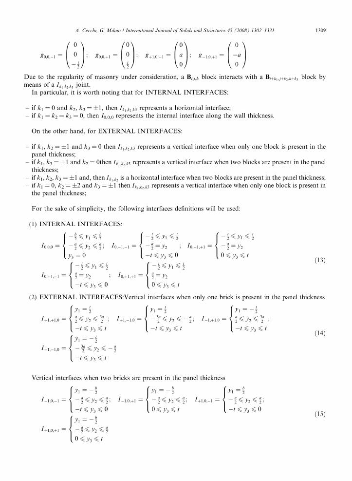
Let gi,j,k be the position of the center of the generic REV in the 3D Euclidean space, b, a and t are bricklength, brick height and brick thickness, respectively. The position of the centers of the four blocks that con-stitute the REV are:
A. Cecchi, G. Milani / International Journal of Solids and Structures 45 (2008) 1302–1331 1309
g0;0;�1 ¼0
0
� t2
0B@1CA; g0;0;þ1 ¼
0
0t2
0B@1CA; gþ1;0;�1 ¼
0
a
0
0B@1CA; g�1;0;þ1 ¼
0
�a
0
0B@1CA
Due to the regularity of masonry under consideration, a Bi,j,k block interacts with a Biþk1;jþk2;kþk3block by
means of a Ik1;k2;k3joint.
In particular, it is worth noting that for INTERNAL INTERFACES:
– if k1 = 0 and k2, k3 = ±1, then Ik1;k2;k3 represents a horizontal interface;– if k1 = k2 = k3 = 0, then I0,0,0 represents the internal interface along the wall thickness.
On the other hand, for EXTERNAL INTERFACES:
– if k1, k2 = ±1 and k3 = 0 then Ik1;k2;k3 represents a vertical interface when only one block is present in thepanel thickness;
– if k1, k3 = ±1 and k2 = 0then Ik1;k2;k3 represents a vertical interface when two blocks are present in the panelthickness;
– if k1, k2, k3 = ±1 and, then Ik1;k2is a horizontal interface when two blocks are present in the panel thickness;
– if k1 = 0, k2 = ±2 and k3 = ±1 then Ik1;k2;k3 represents a vertical interface when only one block is present inthe panel thickness;
For the sake of simplicity, the following interfaces definitions will be used:
(1) INTERNAL INTERFACES:
I0;0;0 ¼� b
26 y1 6
b2
� a26 y2 6
a2
y3 ¼ 0
8><>: ; I0;�1;�1 ¼� t
26 y1 6
t2
� a2¼ y2
�t 6 y3 6 0
;
8><>: I0;�1;þ1 ¼� t
26 y1 6
t2
� a2¼ y2
0 6 y3 6 t
8><>:I0;þ1;�1 ¼
� t26 y1 6
t2
a2¼ y2
�t 6 y3 6 0
8><>: ; I0;þ1;þ1 ¼� t
26 y1 6
t2
a2¼ y2
0 6 y3 6 t
8><>:ð13Þ
(2) EXTERNAL INTERFACES:Vertical interfaces when only one brick is present in the panel thickness
Iþ1;þ1;0 ¼y1 ¼ t
2a26 y2 6
3a2
�t 6 y3 6 t
8><>: ; Iþ1;�1;0 ¼y1 ¼ t
2
� 3a26 y2 6 � a
2
�t 6 y3 6 t
8><>: ; I�1;þ1;0 ¼y1 ¼ � t
2a26 y2 6
3a2
�t 6 y3 6 t
8><>: ;
I�1;�1;0 ¼y1 ¼ � t
2
� 3a26 y2 6 � a
2
�t 6 y3 6 t
8><>:ð14Þ
Vertical interfaces when two bricks are present in the panel thickness
I�1;0;�1 ¼y1 ¼ � b
2
� a26 y2 6
a2
�t 6 y3 6 0
8><>: ; I�1;0;þ1 ¼y1 ¼ � b
2
� a26 y2 6
a2
0 6 y3 6 t
8><>: ; Iþ1;0;�1 ¼y1 ¼ b
2
� a26 y2 6
a2
�t 6 y3 6 0
8><>: ;
Iþ1;0;þ1 ¼y1 ¼ � b
2
� a26 y2 6
a2
0 6 y3 6 t
8><>:ð15Þ
1310 A. Cecchi, G. Milani / International Journal of Solids and Structures 45 (2008) 1302–1331
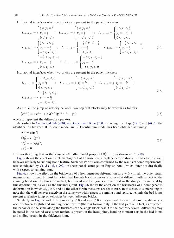
Horizontal interfaces when two bricks are present in the panel thicknesss
Iþ1;þ1;þ1 ¼
t26 y1 6
b2
y2 ¼ a2
0 6 y3 6 t
8><>: ; Iþ1;þ1;�1 ¼
t26 y1 6
b2
y2 ¼ a2
�t 6 y3 6 0
8><>: ; Iþ1;�1;þ1 ¼
t26 y1 6
b2
y2 ¼ � a2
0 6 y3 6 t
8><>: ;
Iþ1;�1;�1 ¼
t26 y1 6
b2
y2 ¼ � a2
�t 6 y3 6 0
8><>: ; I�1;þ1;þ1 ¼� b
26 y1 6 � t
2
y2 ¼ a2
0 6 y3 6 t
8><>: ; I�1;þ1;�1 ¼� b
26 y1 6 � t
2
y2 ¼ a2
�t 6 y3 6 0
8><>: ;
I�1;�1;þ1 ¼� b
26 y1 6 � t
2
y2 ¼ � a2
0 6 y3 6 t
8><>: ; I�1;�1;�1 ¼� b
26 y1 6 � t
2
y2 ¼ � a2
�t 6 y3 6 0
8><>:
ð16Þ
Horizontal interfaces when two bricks are present in the panel thickness
I0;þ2;þ1 ¼� t
26 y1 6
t2
y2 ¼ 3a2
0 6 y3 6 t
8><>: ; Iþ1;þ2;�1 ¼� t
26 y1 6
t2
y2 ¼ 3a2
�t 6 y3 6 0
8><>: ; I0;�2;þ1 ¼� t
26 y1 6
t2
y2 ¼ � 3a2
0 6 y3 6 t
8><>: ;
Iþ1;�2;�1 ¼� t
26 y1 6
t2
y2 ¼ � 3a2
�t 6 y3 6 0
8><>:ð17Þ
As a rule, the jump of velocity between two adjacent blocks may be written as follows:
½wk1;k2 � ¼ Dwk1;k2 þ DXk1;k2ðgiþk1;jþk2 � gi;jÞ ð18Þ
where D represent the difference operator.According to Cecchi and Sab (2004) and Cecchi and Rizzi (2003), starting from Eqs. (1) (3) and (4) (5), theidentification between 3D discrete model and 2D continuum model has been obtained assuming:
wi;j ¼ wðgi;jÞXi;j
32 ¼ x1ðgi;jÞXi;j
31 ¼ �x2ðgi;jÞXi;j
12 ¼ 0
ð19Þ
It is worth noting that in the Reissner–Mindlin model proposed Xi;j12 ¼ 0, as shown in Eq. (19).
Fig. 5 shows the effect on the elementary cell of homogeneous in-plane deformations. In this case, the wallbehaves similarly to running bond texture. Such behavior is also confirmed by the results of some experimentaltests conducted by Calvi et al. (1992) on shear panels arranged in English bond, which differ not drasticallywith respect to running bond.
Fig. 6a shows the effect on the brickwork of a homogeneous deformation x1,1 5 0 with all the other strainmeasures set to zero. It must be noted that English bond behavior is somewhat different with respect to therunning bond one. In this case in fact, both head and bed joints are involved in the dissipation induced bythis deformation, as well as the thickness joint. Fig. 6b shows the effect on the brickwork of a homogeneousdeformation in which x2,2 5 0 and all the other strain measures are set to zero. In this case, it is interesting tonote that the wall behaves exactly in the same way with respect to running bond texture, i.e. only the bed jointspresent a relative jump of velocities between adjacent bricks.
Similarly, in Fig. 6c and d the cases x1,2 5 0 and x2,1 5 0 are examined. In the first case, no differencesoccur between English and running bond texture (there is torsion only in the bed joints); in fact, as expected,the behavior is the same along the thickness of the single block case. On the contrary several differences maybe noted in the second case, since torsion is present in the head joints, bending moment acts in the bed jointsand sliding occurs in the thickness joint.

Fig. 5. Elementary in-plane homogeneous deformations applied to the representative volume element. (a) _E11, (b) _E12, (c) _E21, (d) _E22.
A. Cecchi, G. Milani / International Journal of Solids and Structures 45 (2008) 1302–1331 1311
Finally, Fig. 7 refers to the evaluation of the shear constants and shows shear deformation rates. In par-ticular, Fig. 7a shows the _c13 component, while Fig. 7b the _c23 component.
3. The linear programming problem at a cell level
In this section, a numerical procedure to obtain macroscopic in- and out-of-plane failure surfaces for multi-wythes masonry is presented. Reissner–Mindlin plate hypotheses with infinitely resistant bricks and jointsreduced to interfaces are assumed. For joints, a perfect plastic behavior obeying an associated flow rule is alsoadopted.
The utilization of classical limit analysis theorems allows the combined utilization of simplified or rigoroushomogenization and linear programming. In this framework, Suquet (1983) proved that macroscopic strengthdomains for periodic arrangements of heterogeneous materials may be obtained assuming a rigid-plasticbehavior and associated flow rule for the constituent materials, by means of both static and kinematic theo-rems of limit analysis. Such approaches have been widely applied for the evaluation of both in-plane (deBuhan and de Felice, 1997; Milani et al., 2006a) and out-of-plane failure surfaces of masonry (Milaniet al., 2006b; Sab, 2003; Cecchi et al., 2007) for running bond textures.
On the contrary, at present and despite the great importance of the problem, there is still a lack of knowl-edge concerning the derivation of the macroscopic failure surfaces for double-wythes thickness masonrypanels.
Experimental evidences show that basic failure modes for masonry walls with weak mortar are a mixing ofsliding along the joints, direct tensile splitting of the joints and compressive crushing at the interface between
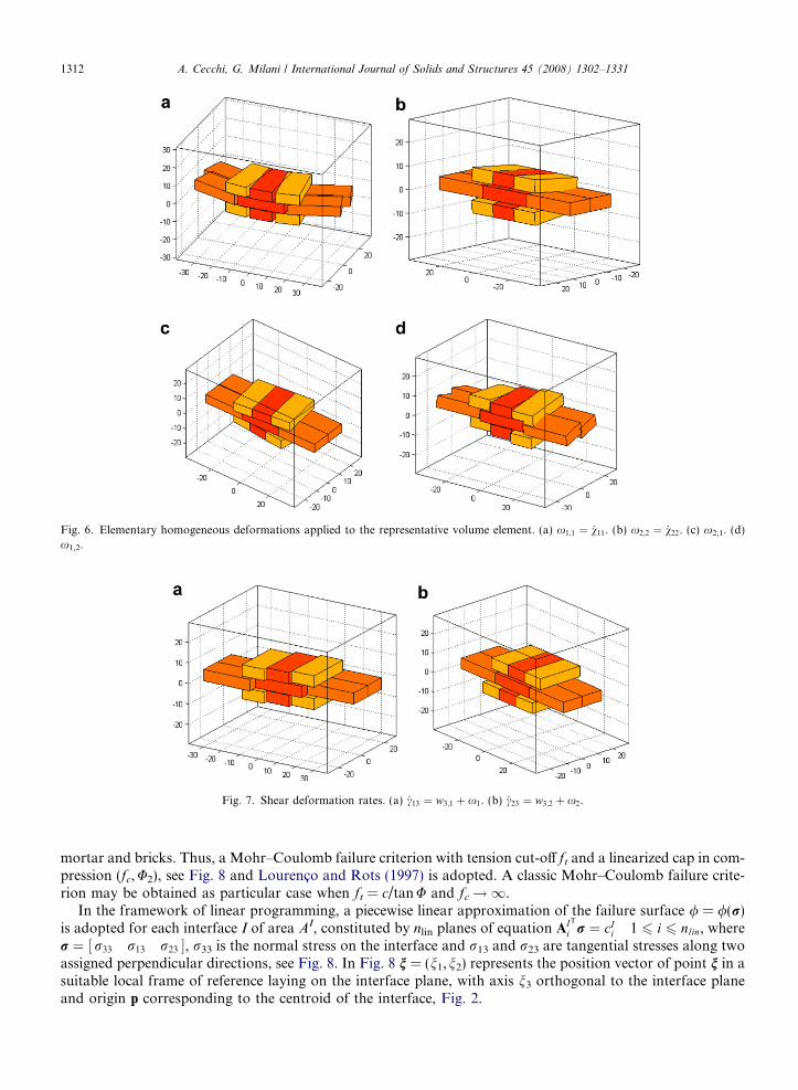
Fig. 6. Elementary homogeneous deformations applied to the representative volume element. (a) x1;1 ¼ _v11. (b) x2;2 ¼ _v22. (c) x2,1. (d)x1,2.
Fig. 7. Shear deformation rates. (a) _c13 ¼ w3;1 þ x1. (b) _c23 ¼ w3;2 þ x2.
1312 A. Cecchi, G. Milani / International Journal of Solids and Structures 45 (2008) 1302–1331
mortar and bricks. Thus, a Mohr–Coulomb failure criterion with tension cut-off ft and a linearized cap in com-pression (fc,U2), see Fig. 8 and Lourenco and Rots (1997) is adopted. A classic Mohr–Coulomb failure crite-rion may be obtained as particular case when ft = c/tanU and fc!1.
In the framework of linear programming, a piecewise linear approximation of the failure surface / = /(r)is adopted for each interface I of area AI, constituted by nlin planes of equation AIT
i r ¼ cIi 1 6 i 6 nlin, where
r ¼ r33 r13 r23½ �, r33 is the normal stress on the interface and r13 and r23 are tangential stresses along twoassigned perpendicular directions, see Fig. 8. In Fig. 8 n = (n1,n2) represents the position vector of point n in asuitable local frame of reference laying on the interface plane, with axis n3 orthogonal to the interface planeand origin p corresponding to the centroid of the interface, Fig. 2.

f : compression strength
: compression linearized capft
c : cohesion
13
c
c
f : tensile strengtht
2
2
c
f : friction angle
33
13
c
33
Horizontal Interface
3 axis
2 axis
2 axis
23
1 axis
1 axis
Vertical Interface
3 axis
23
3 axis
1 axis
vertical joint of thickness interface
2 axis
a b
Fig. 8. Piecewise linear approximation of the failure criterion adopted for joints. (a) Mohr–Coulomb failure criterion with tension cut-offand linearized compression cap, (b) classic Mohr–Coulomb failure criterion.
A. Cecchi, G. Milani / International Journal of Solids and Structures 45 (2008) 1302–1331 1313
Due to the linear interpolation of the displacements jump of joints reduced to interfaces (see Eq. (2)), 3 Æ nlin
independent plastic multiplier rates are assumed as optimization variables for each interface.As already stated in Cecchi et al. (2007), a simple set of three linear equations involving plastic multiplier
rates fields _kIi ðn1; n2Þ and velocity jump [w(n1,n2)] may be written in each point n ¼ n1 n2½ � 2 I :
½wðn1; n2Þ� ¼Xnlin
i¼1
_kIi ðn1; n2Þ
o/or
ð20Þ
In Eq. (20), we assume that ½wðn1; n2Þ� ¼ Dw33 Dw13 Dw23½ �T is the jump of velocity field (linear in(n1,n2)) on the Ith interface and Dwij corresponds to the jump along the direction j, whereas _kI
i ðn1; n2Þ is theith plastic multiplier rate field (linear in (n1,n2)) of the interface I, associated to the ith linearization planeof the failure surface.
In order to satisfy Eq. (20) for each point of the interface I, nine equality constraints for each interface haveto be imposed, that corresponds to evaluate (20) in three different and not aligned positions nk ¼ ðnk
1; nk2Þ on the
interface I as follows:
½wðnk1; n
k2Þ� ¼
Xnlin
i¼1
_kIi ðn
k1; n
k2Þ
o/or
k ¼ 1; 2; 3 ð21Þ
where _kIi ðn
k1; n
k2Þ is the is ith plastic multiplier rate of the interface I evaluated in correspondence of
nk ¼ ðnk1; n
k2Þ.

1314 A. Cecchi, G. Milani / International Journal of Solids and Structures 45 (2008) 1302–1331
Internal power dissipation occurs only on interfaces. For a generic Ith interface, such dissipation is definedas the product of the interface stress vector for the jump of velocities field, i.e. from Eq. (20):
pIint ¼
ZAI½w�TrdAI ¼
ZAI
Xnlin
i¼1
_kIi ðn1; n2Þ
o/or
� �T
rdAI ¼ 1
3
Xnlin
i¼1
cIi
X3
k¼1
_kIi ðn
k1; n
k2ÞAI ð22Þ
where cIi is the right hand side of the ith linearization plane of the interface I failure surface.
External power dissipated can be written as pext ¼ ðRT0 þ kRT
1 ÞD, where R0 is the vector of permanent loads,k is the load multiplier, RT
1 is the vector of loads dependent on the load multiplier (i.e. the optimization direc-tion in the space of macroscopic stresses) and D is the vector of macroscopic kinematic descriptors. D collectsin-plane deformation rates ( _E11
_E12_E22), out-of-plane deformation rates ð _v11 _v12 _v22Þ and shear deformation
rates ð _c13 _c23Þ, see Figs. 5–7. As the amplitude of the failure mechanism is arbitrary, a further normalizationcondition RT
1 D ¼ 1 is usually introduced. Hence, the external power becomes linear in D and k and can bewritten as follows pext ¼ RT
0 Dþ k.Due to the linearity of all the constraints, from Eqs. (18) and (19), a linear relation between D and [w(n1,n2)]
may be written for each interface I as follows:
½wðn1; n2Þ� ¼ GIðn1; n2ÞD ð23Þ
where GI(n1,n2) is a 3 · 10 matrix which depends only on the geometry of the interface under consideration.From Eqs. (20)–(23), the following constrained minimization problem may be finally obtained:
k ¼ minx¼½D;kI
i ðnkÞ�
PnI
I¼1
pIint � RT
0 D
RT1 D ¼ 1
GIðnkÞD ¼ ½wðnkÞ� ¼Pnlin
i¼1
_kIi ðn
k1; n
k2Þ
o/or
nk 2 I
8>>>>>><>>>>>>:ð24Þ
where nI is the total number of interfaces considered and x is the vector of total optimization unknowns.Problem (24) leads to reproduce the macroscopic combined in- and out-of-plane failure surfaces of
masonry through a kinematic approach.From a numerical point of view, macroscopic masonry failure surfaces may be obtained solving repeatedly
a suitable linear programming problem derived from (24). In particular, if bU ¼ bUðN 11;N 12;N 22;M11;M12;M22; T 13; T 23Þ is the macroscopic failure surface in six dimensions for masonry and ifR = (N11, N12, N22, M11, M12, M22, T13, T23) is the vector of macroscopic unknowns ultimate strength ofmasonry, a 2D representation of bU with respect to variables Ri and Rj can be obtained when a direction versor
M22
M12
M11
n macroscopic strength domain
T = T = N = N = N = 013 23 1211 22
Fig. 9. Meaning of nR in the special 3D case R = (M11, M12, M22).
A. Cecchi, G. Milani / International Journal of Solids and Structures 45 (2008) 1302–1331 1315
nR representing a macroscopic direction of the load such that [nR]Tnk = 0 " k 5 i,j is chosen. Under thesehypotheses, the following optimization problem is obtained from (24):
TableMecha
Model
U
c
minfkg ¼PnI
I¼1
pIint � RT
0 D
nTRD ¼ 1 nT
Rnk ¼ 0 8 k 6¼ i; j
GIðnkÞD ¼ ½wðnkÞ� ¼Pnlin
i¼1
_kIi ðn
k1; n
k2Þ o/
or
8>>>>><>>>>>:ð25Þ
where
– k represents the collapse load when a direction nR in the R space (see Fig. 9) is assigned;– nk is a versor such that Rk = Rnk;– i and j represent the axes of projection of bU.
4. English bond out-of-plane failure surfaces
In this section, some cases of technical interest are discussed in detail, with the aim of testing both the dif-ferences in terms of strength domain when passing from a running bond to an English bond texture and theinfluence of shear T13 � T23 macroscopic actions on the ultimate moments. Since no literature results areavailable for English bond behavior at collapse, only comparisons with running bond textures arediscussed.
In the first example, Section 4.1, the influence of shear T13 � T23 macroscopic actions on the ultimatemasonry horizontal bending, torsional and vertical bending moments (i.e. M11, M12 and M22) is addressed.
Two constitutive laws are utilized and critically compared for mortar joints, consisting of a classic Mohr–Coulomb (called here Model A) and a linearized Lourenco and Rots (1997) failure criterion (denoted asModel B). Assuming T13 = T23 = 0, a comparison between running bond and English bond texture is also pro-vided. Finally, two different vertical membrane loads N22 are applied and some sections M11 �M22 andM11 �M12 of the macroscopic failure surface are reported varying T13 and T23.
In the second example, the relevant influence of vertical compressive membrane loads on M11, M12 and M22
failure moments is addressed. As already pointed out for running bond textures (Cecchi et al., 2007), there isan optimal compressive load for which failure moments reach a maximum. Exceeded this optimum point, out-of-plane strength begins to decrease until membrane compressive failure occurs. Since joints failure is not pos-sible in compression when a classic Mohr–Coulomb failure criterion is adopted, this important phenomenoncan be reproduced only using Model B.
4.1. M11 �M12 �M22 failure surface sections for different assigned T13 � T23
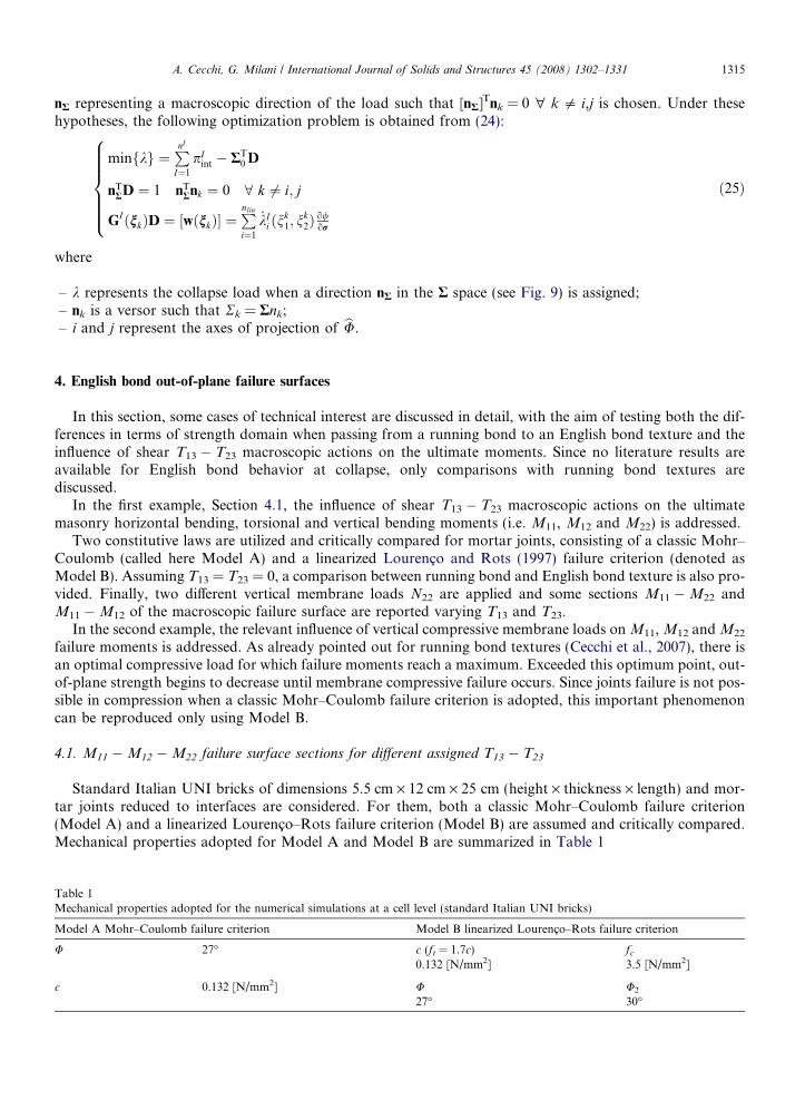
Standard Italian UNI bricks of dimensions 5.5 cm · 12 cm · 25 cm (height · thickness · length) and mor-tar joints reduced to interfaces are considered. For them, both a classic Mohr–Coulomb failure criterion(Model A) and a linearized Lourenco–Rots failure criterion (Model B) are assumed and critically compared.Mechanical properties adopted for Model A and Model B are summarized in Table 1
1nical properties adopted for the numerical simulations at a cell level (standard Italian UNI bricks)
A Mohr–Coulomb failure criterion Model B linearized Lourenco–Rots failure criterion
27� c (ft = 1.7c) fc
0.132 [N/mm2] 3.5 [N/mm2]
0.132 [N/mm2] U U2
27� 30�

1316 A. Cecchi, G. Milani / International Journal of Solids and Structures 45 (2008) 1302–1331
The goal of the comparison is to evaluate both the influence of texture (English bond versus running bond)and the role of masonry out-of-plane shear strength T13 � T23 on the macroscopic out-of-plane failure surface,in presence of different mechanical characteristics for mortar joints.
In Fig. 10a and b, respectively, several sections M11 �M22 and M11 �M12 of the macroscopic failure sur-face bU are reported for Model A varying T13 from zero to T 13 ¼ T f
13, where T f13represents masonry failure
when a pure T13 action is applied.The same comparisons for Model A are illustrated in Fig. 11a and b varying T23 from zero to T 23 ¼ T f
23.As reported in Fig. 12, such surfaces are rather different with respect to those obtained by Cecchi et al.
(2007) when a running bond texture is considered and T13 = T23 = 0, meaning that texture plays a not negli-gible role at failure, especially when out-of-plane actions are considered. In particular it must be noted that, inthis case, English bond pure M11 ultimate bending is greater than the corresponding running bond case. Thisphenomenon may be justified with the shear strength of the thickness joint in conjunction with the torsionalresistance of horizontal joints.
It is worth noting that authors experienced no technically meaningful differences between Model A andModel B in absence of vertical membrane compressive load, as a consequence of the fact that out-of-planefailure is mostly related to tensile cracking. Therefore only Model A results are reported for the sake ofconciseness.
On the contrary, significant differences occur between the models when a vertical membrane compressiveload is applied. In Fig. 13a and b, several sections M11 �M22 and M11 �M12 of the masonry failure strengthdomain are reported for Model A varying T13 and assuming N22 = 60 daN/mm.
Fig. 10. Model A failure surface sections for different values of T13. (a) M11 �M22 sections. (b) M11 �M12 sections.
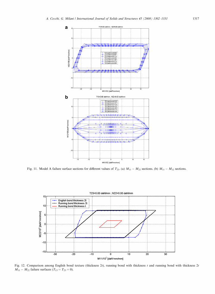
Fig. 11. Model A failure surface sections for different values of T23. (a) M11 �M22 sections. (b) M11 �M12 sections.
Fig. 12. Comparison among English bond texture (thickness 2t), running bond with thickness t and running bond with thickness 2t
M11 �M22 failure surfaces (T13 = T23 = 0).
A. Cecchi, G. Milani / International Journal of Solids and Structures 45 (2008) 1302–1331 1317

Fig. 13. (a) Model A, M11 �M22 failure surfaces at different values of T13. (b) Model A, M11 �M12 failure surfaces at different values ofT13. (c) Model B, M11 �M22 failure surfaces at different values of T13. (d) Model B, M11 �M12 failure surfaces at different values of T13.
1318 A. Cecchi, G. Milani / International Journal of Solids and Structures 45 (2008) 1302–1331
In Fig. 13c and d the same results are reported adopting Model B. As can be noted by comparing the failurecurves, evident differences occur between the models. In particular the greater strength of Model A withrespect to Model B under pure M22 ultimate bending (approximately 6000 da N/mm * mm versus1000 da N/mm * mm) underlines that a limited compressive strength influences the ultimate out-of-plane resis-tance in presence of not negligible vertical membrane compressive loads.
The examples discussed underline that masonry macroscopic failure surface results dependent both on thegeometrical and mechanical characteristics assumed for the components and that the proposed model is ableto reproduce different macroscopic strength domains whenever different failure behaviors for the componentsare taken into account.
4.2. Influence of the vertical compressive membrane load
The aim of this section is to show the influence of membrane compressive loads (kept constant) on the out-of-plane masonry failure surface, when an English bond texture is considered.
For the simulations, common Italian UNI bricks of dimensions 5.5 cm · 12 cm · 25 cm (height · thick-ness · length) are adopted.
As in the previous case, joints are reduced to interfaces adopting for mortar both a classic Mohr–Coulombfailure surface (Model A) and a frictional-type failure surface with tensile and compressive cut-off (Model B).Mechanical characteristics adopted for both models are summarized in Table 1.
A. Cecchi, G. Milani / International Journal of Solids and Structures 45 (2008) 1302–1331 1319
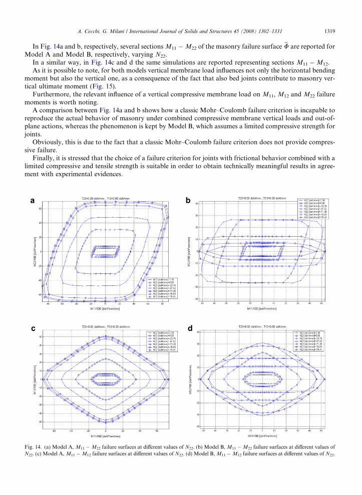
In Fig. 14a and b, respectively, several sections M11 �M22 of the masonry failure surface bU are reported forModel A and Model B, respectively, varying N22.
In a similar way, in Fig. 14c and d the same simulations are reported representing sections M11 �M12.As it is possible to note, for both models vertical membrane load influences not only the horizontal bending
moment but also the vertical one, as a consequence of the fact that also bed joints contribute to masonry ver-tical ultimate moment (Fig. 15).
Furthermore, the relevant influence of a vertical compressive membrane load on M11, M12 and M22 failuremoments is worth noting.
A comparison between Fig. 14a and b shows how a classic Mohr–Coulomb failure criterion is incapable toreproduce the actual behavior of masonry under combined compressive membrane vertical loads and out-of-plane actions, whereas the phenomenon is kept by Model B, which assumes a limited compressive strength forjoints.
Obviously, this is due to the fact that a classic Mohr–Coulomb failure criterion does not provide compres-sive failure.
Finally, it is stressed that the choice of a failure criterion for joints with frictional behavior combined with alimited compressive and tensile strength is suitable in order to obtain technically meaningful results in agree-ment with experimental evidences.
Fig. 14. (a) Model A, M11 �M22 failure surfaces at different values of N22. (b) Model B, M11 �M22 failure surfaces at different values ofN22. (c) Model A, M11 �M12 failure surfaces at different values of N22. (d) Model B, M11 �M12 failure surfaces at different values of N22.
0
70605040
30
10 020 30
20
10
20
2040
0
40
20
10
30
40
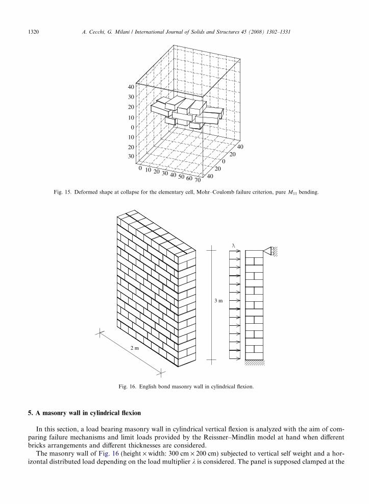
Fig. 15. Deformed shape at collapse for the elementary cell, Mohr–Coulomb failure criterion, pure M11 bending.
2 m
3 m
Fig. 16. English bond masonry wall in cylindrical flexion.
1320 A. Cecchi, G. Milani / International Journal of Solids and Structures 45 (2008) 1302–1331
5. A masonry wall in cylindrical flexion
In this section, a load bearing masonry wall in cylindrical vertical flexion is analyzed with the aim of com-paring failure mechanisms and limit loads provided by the Reissner–Mindlin model at hand when differentbricks arrangements and different thicknesses are considered.
The masonry wall of Fig. 16 (height · width: 300 cm · 200 cm) subjected to vertical self weight and a hor-izontal distributed load depending on the load multiplier k is considered. The panel is supposed clamped at the
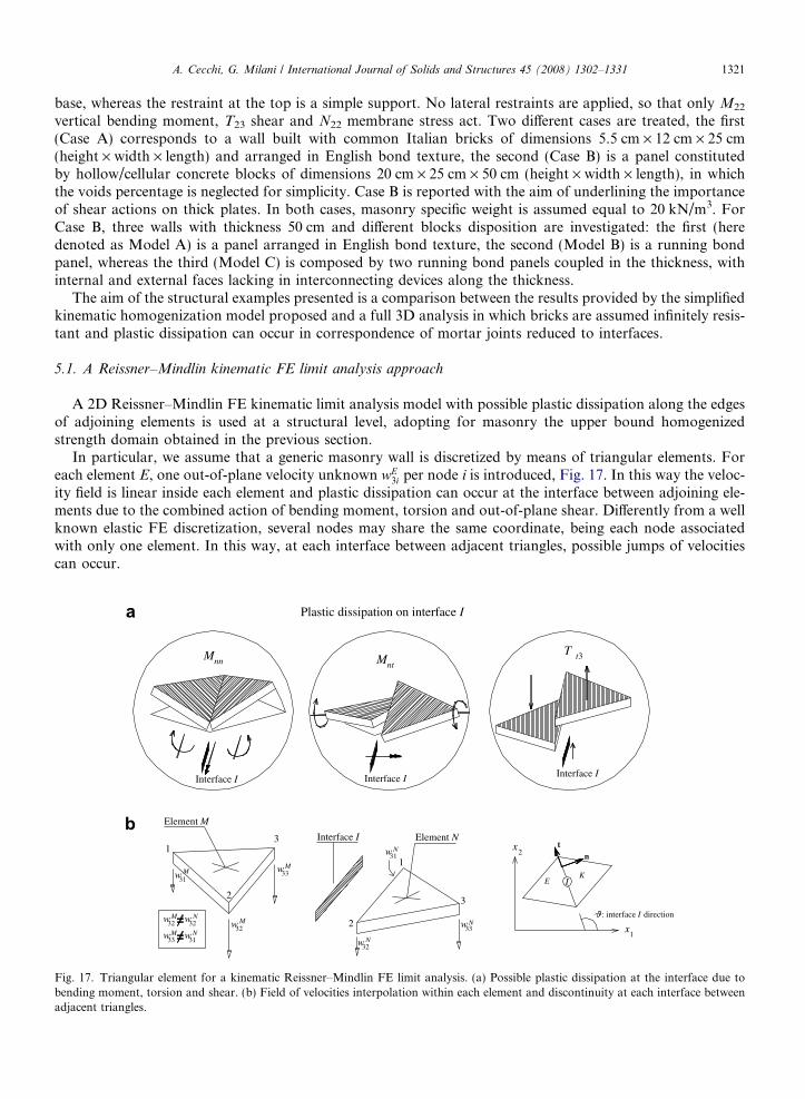
A. Cecchi, G. Milani / International Journal of Solids and Structures 45 (2008) 1302–1331 1321
base, whereas the restraint at the top is a simple support. No lateral restraints are applied, so that only M22
vertical bending moment, T23 shear and N22 membrane stress act. Two different cases are treated, the first(Case A) corresponds to a wall built with common Italian bricks of dimensions 5.5 cm · 12 cm · 25 cm(height · width · length) and arranged in English bond texture, the second (Case B) is a panel constitutedby hollow/cellular concrete blocks of dimensions 20 cm · 25 cm · 50 cm (height · width · length), in whichthe voids percentage is neglected for simplicity. Case B is reported with the aim of underlining the importanceof shear actions on thick plates. In both cases, masonry specific weight is assumed equal to 20 kN/m3. ForCase B, three walls with thickness 50 cm and different blocks disposition are investigated: the first (heredenoted as Model A) is a panel arranged in English bond texture, the second (Model B) is a running bondpanel, whereas the third (Model C) is composed by two running bond panels coupled in the thickness, withinternal and external faces lacking in interconnecting devices along the thickness.
The aim of the structural examples presented is a comparison between the results provided by the simplifiedkinematic homogenization model proposed and a full 3D analysis in which bricks are assumed infinitely resis-tant and plastic dissipation can occur in correspondence of mortar joints reduced to interfaces.
5.1. A Reissner–Mindlin kinematic FE limit analysis approach
A 2D Reissner–Mindlin FE kinematic limit analysis model with possible plastic dissipation along the edgesof adjoining elements is used at a structural level, adopting for masonry the upper bound homogenizedstrength domain obtained in the previous section.
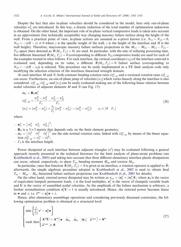
In particular, we assume that a generic masonry wall is discretized by means of triangular elements. Foreach element E, one out-of-plane velocity unknown wE
3i per node i is introduced, Fig. 17. In this way the veloc-ity field is linear inside each element and plastic dissipation can occur at the interface between adjoining ele-ments due to the combined action of bending moment, torsion and out-of-plane shear. Differently from a wellknown elastic FE discretization, several nodes may share the same coordinate, being each node associatedwith only one element. In this way, at each interface between adjacent triangles, possible jumps of velocitiescan occur.
Interface I
Plastic dissipation on interface I
Interface I
31
32
33
32
w
w
w
w
32
32w
w
2
2
31w
1
33
Interface I
w
3
Mnn
Interface I
33w
3
x1
: interface I direction
t2
x31
E
1w
KI
n
ntM t3T
Element M
Element N
M
M
M
M
M N
N
N
N
N
Fig. 17. Triangular element for a kinematic Reissner–Mindlin FE limit analysis. (a) Possible plastic dissipation at the interface due tobending moment, torsion and shear. (b) Field of velocities interpolation within each element and discontinuity at each interface betweenadjacent triangles.
1322 A. Cecchi, G. Milani / International Journal of Solids and Structures 45 (2008) 1302–1331
Despite the fact that also in-plane velocities should be considered in the model, here only out-of-planevelocities wE
3i are introduced. In this way, a drastic reduction of the total number of optimization unknownsis obtained. On the other hand, the important role of in-plane vertical compressive loads is taken into accountin an approximate (but technically acceptable) way changing masonry failure surface along the height of thewall. From a practical point of view, in-plane actions are assumed as a-priori known (i.e. N11 = N12 = 0,N22 = �c(H � z) 5 0 where c is the specific weight of the wall, z is the height of the interface and H is thewall height). Therefore, macroscopic masonry failure surfaces projections in the M11 �M22 �M12 � T13 �T23 space (here denoted as bUðMij; T ijÞ ¼ 0Þ are used. In particular, with the aim of reducing processing time,five different linearized bUðMij; T ijÞ ¼ 0 (corresponding to different N22 compressive loads) are used for each ofthe examples treated in what follows. For each interface, the vertical coordinate (zb) of the interface centroid isevaluated and, depending on its value, a different bUðMij; T ijÞ ¼ 0 failure surface (corresponding toN22 = �c(H � zb)) is selected. This procedure can be easily implemented in a FE limit analysis code onlymodifying the selection criterion of the interfaces linearized strength domain.
At each interface M and N, both constant bending rotation rates _xnnN�M and a torsional rotation rates _xnt
N�M
can occur. Furthermore, an out-of-plane jump of velocities [w3] which varies linearly along the interface is alsoconsidered. _xnn
N�M , _xntN�M and [w3] can be easily evaluated making use of the following linear relation between
nodal velocities of adjacent elements M and N (see Fig. 17):
_xN ¼ BN wN3
_xntN�M ¼
wM3j � wM
3i
CI�
wN3j � wN
3k
CI
½w3� ¼ ðwM3j � wN
3jÞ þxI
CI½ðwM
3i � wN3kÞ � ðwM
3j � wN3jÞ� xI 2 0 CI½ �
ð26Þ
where:
– wN3 ¼ wN
3i wN3j wN
3k
� �T;
– BN is a 3 · 3 matrix that depends only on the finite element geometry;– _xN ¼ _xN
i _xNj _xN
k
� �Tare the side normal rotation rates, linked with _xnn
N�M by means of the linear equa-tion _xnn
N�M ¼ _xNi � _xM
i ;– CI is the interface length.
Power dissipated at each interface between adjacent triangles (pI) may be evaluated following a generalapproach recently presented in the technical literature for the limit analysis of plane-strain problems (seeKrabbenhoft et al., 2005) and taking into account that three different elementary interface plastic dissipationscan occur, related, respectively, to shear Tnt, bending moment Mnn and torsion Mnt.
In particular, once that function bUðMij; T ijÞ ¼ 0 is given at an interface, a rotation operator is applied to bU;afterwards, the simple algebraic procedure adopted in Krabbenhoft et al., 2005 is used to obtain finalTnt �Mnn �Mnt linearized failure surfaces projections (see Krabbenhoft et al., 2005 for details).
On the other hand, external power dissipated may be written as pext ¼ ðpT0 þ kpT
1 ÞU, where p0 is the vectorof (equivalent lumped) permanent loads, k is the load multiplier, pT
1 is the vector of (lumped) variable loadsand U is the vector of assembled nodal velocities. As the amplitude of the failure mechanism is arbitrary, afurther normalization condition pT
1 U ¼ 1 is usually introduced. Hence, the external power becomes linearin w and k, i.e. P ex ¼ pT
0 wþ k.Hence, after elementary assemblage operations and considering previously discussed constraints, the fol-
lowing optimization problem is obtained at a structural level:
minPnI
i¼1
pI � pT0 w
( )
such thatAeqU ¼ Aeq
w ~_xnn~_xnt ½~w3� _kI ;ass
� �¼ beq
_kI;ass P 0
(8>>>>><>>>>>:
ð27Þ
A. Cecchi, G. Milani / International Journal of Solids and Structures 45 (2008) 1302–1331 1323
where:
– U ¼ w ~_xnn~_xnt ½~w3� _kI;ass
� �is the vector of global unknowns, which collects the vector of assembled
nodal velocities (w), the vector of assembled bending interface rotation rates (~_xnnÞ, the vector of assembledtorsion interface rotation rates (~_xntÞ, the vector of assembled jumps of velocities on interfaces (½~w3�Þ and thevector of assembled interface plastic multiplier rates ( _kI;assÞ.
– Aeq is the overall constraints matrix and collects velocity and rotation boundary conditions, Eq. (26) andconstraints for plastic flow in velocity discontinuities.
5.2. Heterogeneous full 3D kinematic FE limit analysis approach
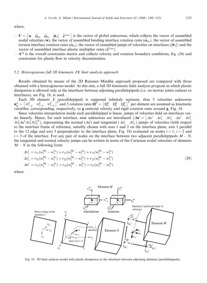
Results obtained by means of the 2D Reissner–Mindlin approach proposed are compared with thoseobtained with a heterogeneous model. At this aim, a full 3D kinematic limit analysis program in which plasticdissipation is allowed only at the interfaces between adjoining parallelepipeds (i.e. on mortar joints reduces tointerfaces), see Fig. 18, is used.
Each 3D element E (parallelepiped) is supposed infinitely resistant, thus 3 velocities unknownswE
g ¼ wE1�g wE
2�g wE3�g
� �Tand 3 rotation rates XE ¼ XE
1 XE2 XE
3
� �Tper element are assumed as kinematic
variables, corresponding, respectively, to g centroid velocity and rigid rotation rates around g, Fig. 18.Since velocities interpolation inside each parallelepiped is linear, jumps of velocities field on interfaces var-
ies linearly. Hence, for each interface, nine unknowns are introduced DuI ¼ Du1 Dv11 Dv1
2 Du2 Dv21
��Dv2
2Du3Dv31Dv3
2�TÞ, representing the normal (Dui) and tangential ( Dvi
1 Dvi2 Þ jumps of velocities (with respect
to the interface frame of reference, suitably chosen with axes 1 and 2 on the interface plane, axis 1 parallelto the 12 edge and axis 3 perpendicular to the interface plane, Fig. 18) evaluated on nodes i = 1, i = 2 andi = 3 of the interface. For any pair of nodes on the interface between two adjacent parallelepipeds M � N,the tangential and normal velocity jumps can be written in terms of the Cartesian nodal velocities of elementsM � N in the following form:
Dvf1 ¼ r11ðwMp
1 � wNs1 Þ þ r12ðwMp
2 � wNs2 Þ þ r13ðwMp
3 � wNs3 Þ
Dvf2 ¼ r21ðwMp
1 � wNs1 Þ þ r22ðwMp
2 � wNs2 Þ þ r23ðwMp
3 � wNs3 Þ
Duf ¼ r31ðwMp1 � wNs
1 Þ þ r32ðwMp2 � wNs
2 Þ þ r33ðwMp3 � wNs
3 Þð28Þ
where
2
3w 4
Mw
Axisinterface
Axis // to 1-21
1w
Element N
3-gtranslations2w
2
3
rotations
3
w2-g
1-ggg
Mw
M
Element MM
1v v
v2
14
Interface I and local frame of reference
v2
1
u11
v
1v2
1
4
u
v
1
2
u4
4
Element M
v22 2
2u
1M
M
nt
nr
nn
Stress acting on the interface I
t
r
n
Fig. 18. 3D limit analysis model with plastic dissipation at the interfaces between adjoining elements (parallelepipeds).
1324 A. Cecchi, G. Milani / International Journal of Solids and Structures 45 (2008) 1302–1331
– the first apex of wi in capital letters identifies the element (M or N), while the second identifies the nodenumber of the element (p = k,j,q or s = i,j,k);
– f = 1,2,3;– rij = (Dvi/kDvik)Tej; (Dvi/kDvik) represents the versor of the ith axis of the local frame of reference, whereas
ej indicates the versor of the jth axis of the global frame of reference.
After elementary assemblage operations on (28), it is possible to show that, for each interface, the followingequations can be written:
Aeq11wMp þ Aeq
12wNs þ Aeq13DuI ¼ 0 ð29Þ
where wMp and wNs are 6 · 1 vectors that collect centroid velocities and rotation rates of elements M and N,respectively, and A
eq11, A
eq12, A
eq13 are matrices which depend only on the geometry of the elements M and N.
In order to evaluate power dissipation pI on interfaces, for each interface I a linearization of its strengthdomain with N pl
I planes (in the form rnnAInn�i þ sntA
Int�i þ snrA
Inr�i ¼ BI
i i ¼ 1; . . . ;NplI , see Fig. 18), obtained
following what already reported in Section 3, is provided.On the other hand, it is worth noting that recent trends in limit analysis have demonstrated that the line-
arization of the strength domain can be circumvented using conic programming (e.g. Makrodimopoulos andMartin, 2006; Krabbenhoft et al., 2007). This tool is more powerful with respect to LP and could lead to lessexpensive processing times for the 3D heterogeneous analyses, which typically required around 2 h to be pro-cessed on a PC equipped with 512 Mb ram. Nonetheless, here classic interior point LP routines are used forthe sake of simplicity.
Since jump of velocities field varies linearly at each interface, it is necessary to impose plastic flow con-straints on three vertices n of the rectangular interface:
n ¼ 1; 2; 3
Dun ¼PNpl
I
i¼1
_kI ;ni AI
nn�i
Dvn1 ¼
PNplI
i¼1
_kI ;ni AI
nt�i
Dvn2 ¼
PNplI
i¼1
_kI ;ni AI
nr�i
8>>>>>>>>>><>>>>>>>>>>:ð30Þ
where:
– Dun represents the jump of displacements normal to the interface;– Dvn
1 and Dvn2 are jumps of displacement along two perpendicular axes on the interface plane;
– _kI;ni is the plastic multiplier rate of the ith linearization plane of vertex n of the interface I.
Following Eq. (30), within each interface I of area A, the power dissipated is:
pI ¼ A=4X4
n¼1
XNplI
i¼1
_kI;ni BI
i ð31Þ
where node 4 results linearly dependent with respect to previous nodes.As already discussed in this section for the 2D limit analysis approach, external power dissipation can be
written in the form pext ¼ pT0 wþ k, once that a suitable normalization condition is introduced.
Boundary conditions on velocities are imposed in a similar way with respect to classic elastic finite elements,leading to additional equality constraints on elements velocities.
After some elementary assemblage operations, a simple linear programming problem is obtained (analo-gous to that reported in Milani et al., 2007), where the objective function consists in the minimization ofthe total internal power dissipated:

Fig. 19kinema25 cm.
A. Cecchi, G. Milani / International Journal of Solids and Structures 45 (2008) 1302–1331 1325
minPNI
I¼1
pI � pT0 w
( )
such that
AeqU ¼ beq
pT1 U ¼ 1
_kI ;ass P 0
8><>:
8>>>>>>><>>>>>>>:ð32Þ
where:
– NI is the total number of interfaces in which plastic dissipation occurs;– U ¼ w DuI ;ass _kI ;ass
� �Tis the vector of global unknowns, which collects the vector of assembled centroid
velocities (wEg Þ, the vector of assembled parallelepipeds rotations rates (XE
g Þ, the vector of assembled jumpof velocities on interfaces (DuI,ass) and the vector of assembled interface plastic multiplier rates ( _kI;assÞ.
– Aeq (beq) is the overall constraints matrix (right hands vector) and collects velocity boundary conditions,relations between velocity jumps on interfaces and elements velocities and velocity constraints for plasticflow in discontinuities.
5.3. Numerical results
For the wall under consideration, in both cases (i.e. Case A and Case B), a Lourenco–Rots failure criterion(1997) is adopted for mortar joints reduced to interfaces with friction angle U = 27�, cohesion c = 0.15 N/mm2, mortar tensile strength ft = 0.27 N/mm2, mortar compressive strength fc = 5 N/mm2 and linearizedcompressive cap angle U2 = 30�.
For what concerns the kinematic identification approach proposed, a linearization of masonry failuresurface with 100 hyper-planes obtained as illustrated in the previous section is adopted. Furthermore, inthe framework of the compatible identification proposed, a coarse mesh is used for the simulations,Figs. 19 and 20.
In Fig. 19, a comparison between deformed shapes at collapse obtained by means of the kinematic identi-fication model proposed and the full 3D heterogeneous approach is presented for the wall built with commonItalian bricks (Case A). As it is possible to note, perfect agreement in terms of both collapse load and failure
Kinematic model Heterogeneous model
Plastic dissipation
25 0
200 [cm]
300 [cm]
English bond texture, thickness 25 cm. Collapse load:16.4 kN/m
. Masonry panel in cylindrical flexion, English bond texture obtained with common Italian bricks of dimensions. (a) Simplifiedtic model, deformed shape at collapse. (b) Heterogeneous model, deformed shape at collapse. English bond texture, thicknessCollapse load: 16.4 kN/m.
Kinematic model Heterogeneous model
050
200 [cm]
300 [cm]
050
200 [cm]
300 [cm]
50 0
200 [cm]
Internal and external plate elements without interconnections
300 [cm]
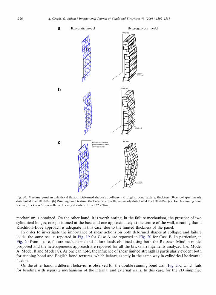
Fig. 20. Masonry panel in cylindrical flexion. Deformed shapes at collapse. (a) English bond texture, thickness 50 cm collapse linearlydistributed load 58 kN/m. (b) Running bond texture, thickness 50 cm collapse linearly distributed load 58 kN/m. (c) Double running bondtexture, thickness 50 cm collapse linearly distributed load 32 kN/m.
1326 A. Cecchi, G. Milani / International Journal of Solids and Structures 45 (2008) 1302–1331
mechanism is obtained. On the other hand, it is worth noting, in the failure mechanism, the presence of twocylindrical hinges, one positioned at the base and one approximately at the centre of the wall, meaning that aKirchhoff–Love approach is adequate in this case, due to the limited thickness of the panel.
In order to investigate the importance of shear actions on both deformed shapes at collapse and failureloads, the same results reported in Fig. 19 for Case A are reported in Fig. 20 for Case B. In particular, inFig. 20 from a to c, failure mechanisms and failure loads obtained using both the Reissner–Mindlin modelproposed and the heterogeneous approach are reported for all the bricks arrangements analyzed (i.e. ModelA, Model B and Model C). As one can note, the influence of shear limited strength is particularly evident bothfor running bond and English bond textures, which behave exactly in the same way in cylindrical horizontalflexion.
On the other hand, a different behavior is observed for the double running bond wall, Fig. 20c, which failsfor bending with separate mechanisms of the internal and external walls. In this case, for the 2D simplified
A. Cecchi, G. Milani / International Journal of Solids and Structures 45 (2008) 1302–1331 1327
homogenized approach (Fig. 20c left), two rows of triangular elements along the thickness with possible plas-tic dissipation for combined bending moment, torsion and out-of-plane shear are utilized, neglecting the pos-sible presence of shear actions at the interface between external and internal layers.
Finally, for all the arrangements analyzed (Fig. 20), the perfect agreement between heterogeneous andhomogenized results is worth noting, meaning that accurate results can be obtained with the simplified kine-matic model proposed.
6. A masonry slab arranged in English bond texture
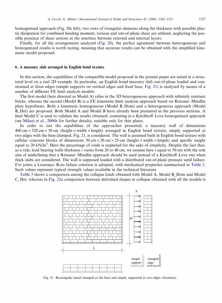
In this section, the capabilities of the compatible model proposed in the present paper are tested at a struc-tural level on a real 2D example. In particular, an English bond masonry slab out-of-plane loaded and con-strained at three edges (simple supports on vertical edges and fixed base, Fig. 21) is analyzed by means of anumber of different FE limit analysis models.
The first model (here denoted as Model A) relies in the 3D heterogeneous approach with infinitely resistantbricks, whereas the second (Model B) is a FE kinematic limit analysis approach based on Reissner–Mindlinplate hypotheses. Both a kinematic homogeneous (Model B_Hom) and a heterogeneous approach (ModelB_Het) are proposed. Both Model A and Model B have already been presented in the previous sections. Afinal Model C is used to validate the results obtained, consisting in a Kirchhoff–Love homogenized approach(see Milani et al., 2006b for further details), suitable only for thin plates.
In order to test the capabilities of the approaches presented, a masonry wall of dimensions400 cm · 320 cm · 50 cm (height · width · length) arranged in English bond texture, simply supported attwo edges with the base clamped, Fig. 21, is considered. The wall is assumed built in English bond texture withcellular concrete blocks of dimensions 50 cm · 20 cm · 25 cm (height · width · length) and specific weightequal to 20 kN/m3. Here the percentage of voids is neglected for the sake of simplicity. Despite the fact that,as a rule, load bearing walls thickness t varies from 20 to 40 cm, we assume here t equal to 50 cm with the soleaim of underlining that a Reissner–Mindlin approach should be used instead of a Kirchhoff–Love one whenthick slabs are considered. The wall is supposed loaded with a distributed out-of-plane pressure until failure.For joints a Lourenco–Rots failure criterion is adopted, with mechanical properties summarized in Table 2.Such values represent typical strength values available in the technical literature.
Table 3 shows a comparison among the collapse loads obtained with Model A, Model B_Hom and ModelC_Het, whereas in Fig. 22a comparison between deformed shapes at collapse obtained with all the models is
L
simplesupport
H
clampededge
Fig. 21. Rectangular panel clamped at the base and simply supported at two edges. Geometry.

Fig. 22. Masonry panel simply supported at three edges. Deformed shapes at collapse (Model A). (a) English bond texture, 3Dheterogeneous approach. (b) English bond texture, heterogeneous 2D (left) and simplified homogeneous kinematic approach (right).
Table 2Masonry slab constrained at three edges
ft [N/mm2] c U fc [N/mm2] U2
0.15 0.8 ft 30� 5 30�
Mechanical characteristics assumed for mortar joints ft, mortar tension cut-off; c, mortar cohesion; U, mortar friction angle; fc, mortarcompressive strength; U2, shape of the linearized compressive cap.
Table 3Masonry slab constrained at three edges
English bond texture t = 50 cm, ultimate pressure [kN/m2]
22.12 Full 3D heterogeneous model (Model A)23.40 Reissner–Mindlin homogeneous kinematic model (Model B_Hom)26.10 Reissner–Mindlin heterogeneous model (Model B_Het)
English bond bricks disposition. Comparison among failure loads obtained using a full heterogeneous 3D model, a 2D kinematichomogeneous Reissner–Mindlin FE limit analysis approach and a 2D heterogeneous Reissner–Mindlin FE limit analysis model.
1328 A. Cecchi, G. Milani / International Journal of Solids and Structures 45 (2008) 1302–1331
reported. Here, it is worth mentioning that for Model B_Het we assume, see Milani et al. (2007), 2D Reissner–Mindlin plate hypotheses with plastic dissipation only on joints reduced to interfaces. Furthermore, verticaljoints disposed along the thickness are not taken into account. Therefore, a collapse load greater than thoseobtained with Model A and Model B_Hom is expected, as confirmed by Table 3.
As it is possible to note from a comparison between Table 3 and Fig. 22, the compatible identificationapproach (Model B_Hom) gives results in excellent agreement with the full 3D heterogeneous one (ModelA). On the other hand, for both models it is particularly evident the influence of the limited shear strength,
A. Cecchi, G. Milani / International Journal of Solids and Structures 45 (2008) 1302–1331 1329
especially at the base of the wall where out-of-plane tangential actions reach their maximum value. The limitedout-of-plane strength is well reproduced also by Model B_Het, which furnishes a collapse load slightly greater.
For what concerns mesh dependence of the models used, it is worth noting that mesh orientation and size oftriangular elements used in Model B_Hom (Fig. 22b) can play a relatively important role when out-of-planemodels with plastic dissipation only at the interfaces between adjoining elements are adopted. On the otherhand, it has been shown with a number of examples (see Milani et al., 2006b; Lourenco et al., in press) thatquite refined meshes with undistorted elements (i.e. �1/10 of the edge length, as is the case here treated) givetechnically acceptable results, with differences on collapse loads obtained with classic elasto-plastic approachesless than 10%.
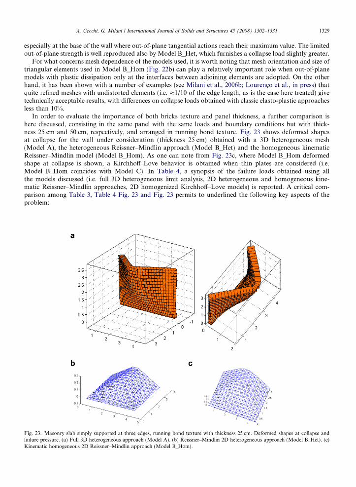
In order to evaluate the importance of both bricks texture and panel thickness, a further comparison ishere discussed, consisting in the same panel with the same loads and boundary conditions but with thick-ness 25 cm and 50 cm, respectively, and arranged in running bond texture. Fig. 23 shows deformed shapesat collapse for the wall under consideration (thickness 25 cm) obtained with a 3D heterogeneous mesh(Model A), the heterogeneous Reissner–Mindlin approach (Model B_Het) and the homogeneous kinematicReissner–Mindlin model (Model B_Hom). As one can note from Fig. 23c, where Model B_Hom deformedshape at collapse is shown, a Kirchhoff–Love behavior is obtained when thin plates are considered (i.e.Model B_Hom coincides with Model C). In Table 4, a synopsis of the failure loads obtained using allthe models discussed (i.e. full 3D heterogeneous limit analysis, 2D heterogeneous and homogeneous kine-matic Reissner–Mindlin approaches, 2D homogenized Kirchhoff–Love models) is reported. A critical com-parison among Table 3, Table 4 Fig. 23 and Fig. 23 permits to underlined the following key aspects of theproblem:
Fig. 23. Masonry slab simply supported at three edges, running bond texture with thickness 25 cm. Deformed shapes at collapse andfailure pressure. (a) Full 3D heterogeneous approach (Model A). (b) Reissner–Mindlin 2D heterogeneous approach (Model B_Het). (c)Kinematic homogeneous 2D Reissner–Mindlin approach (Model B_Hom).
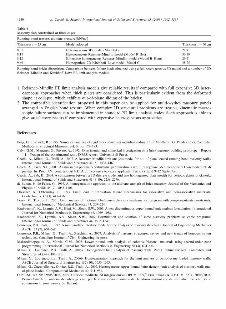
Table 4Masonry slab constrained at three edges
Running bond texture, ultimate pressure [kN/m2]
Thickness t = 25 cm Model adopted Thickness t = 50 cm
8.01 Heterogeneous 3D model (Model A) 29.918.15 Heterogeneous Reissner–Mindlin model (Model B_Het) 30.198.12 Kinematic homogeneous Reissner–Mindlin model (Model B_Hom) 29.919.69 Homogenized 2D Kirchhoff–Love model (Model C) 38.75
Running bond bricks disposition. Comparison between failure loads obtained using a full heterogeneous 3D model and a number of 2DReissner–Mindlin and Kirchhoff–Love FE limit analysis models.
1330 A. Cecchi, G. Milani / International Journal of Solids and Structures 45 (2008) 1302–1331
1. Reissner–Mindlin FE limit analysis models give reliable results if compared with full expensive 3D heter-ogeneous approaches when thick plates are considered. This is particularly evident from the deformedshape at collapse, which exhibits out-of-plane sliding of the bricks;
2. The compatible identification proposed in this paper can be applied for multi-wythes masonry panelsarranged in English bond texture. When complex 2D structural problems are treated, kinematic macro-scopic failure surfaces can be implemented in standard 2D limit analysis codes. Such approach is able togive satisfactory results if compared with expensive heterogeneous approaches.
References
Begg, D., Fishwick, R., 1995. Numerical analysis of rigid block structures including sliding. In: J. Middleton, G. Pande (Eds.), ComputerMethods in Structural Masonry, vol. 3, pp. 177–183.
Calvi, G.M., Magenes, G., Pavese, A., 1992. Experimental and numerical investigation on a brick masonry building prototype – Report1.1 – Design of the experimental tests. D.M.S report, Universita di Pavia.
Cecchi, A., Milani, G., Tralli, A., 2007. A Reissner–Mindlin limit analysis model for out-of-plane loaded running bond masonry walls.International Journal of Solids and Structures 44 (5), 1438–1460.
Cecchi, A., Rizzi, N.L., 2003. Analisi in piu parametri perturbativi per murature a struttura regolare: identificazione 3D con modelli 2D dipiastra. In: Proc. XVI congresso AIMETA di meccanica teorica e applicata, Ferrara (Italy) 9–12 September.
Cecchi, A., Sab, K., 2004. A comparison between a 3D discrete model and two homogenised plate models for periodic elastic brickwork.International Journal of Solids and Structures 41 (9-10), 2259–2276.
de Buhan, P., de Felice, G., 1997. A homogenisation approach to the ultimate strength of brick masonry. Journal of the Mechanics andPhysics of Solids 45 (7), 1085–1104.
Drescher, A., Detournay, E., 1993. Limit load in translation failure mechanisms for associative and non-associative materials.Geotechnique 43 (3), 443–456.
Ferris, M., Tin-Loi, F., 2001. Limit analysis of frictional block assemblies as a mathematical program with complementarity constraints.International Journal of Mechanical Sciences 43, 209–224.
Krabbenhoft, K., Lyamin, A.V., Hjiaj, M., Sloan, S.W., 2005. A new discontinuous upper bound limit analysis formulation. InternationalJournal for Numerical Methods in Engineering 63, 1069–1088.
Krabbenhoft, K., Lyamin, A.V., Sloan, S.W., 2007. Formulation and solution of some plasticity problems as conic programs.International Journal of Solids and Structures 44, 1533–1549.
Lourenco, P.B., Rots, J., 1997. A multi-surface interface model for the analysis of masonry structures. Journal of Engineering MechanicsASCE 123 (7), 660–668.
Lourenco, P.B., Milani, G., Tralli, A., Zucchini, A., 2007. Analysis of masonry structures: review and new trends of homogenisationtechniques. Canadian Journal of Civil Engineering, in press.
Makrodimopoulos, A., Martin, C.M., 2006. Lower bound limit analysis of cohesive-frictional materials using second-order coneprogramming. International Journal for Numerical Methods in Engineering 66 (4), 604–634.
Milani, G., Lourenco, P.B., Tralli, A., 2006a. Homogenised limit analysis of masonry walls. Part I: failure surfaces. Computers andStructures 84 (3-4), 181–195.
Milani, G., Lourenco, P.B., Tralli, A., 2006b. Homogenization approach for the limit analysis of out-of-plane loaded masonry walls.ASCE Journal of Structural Engineering 132 (10), 1650–1663.
Milani, G., Zuccarello, A., Olivito, R.S., Tralli, A., 2007. Heterogeneous upper-bound finite element limit analysis of masonry walls out-of-plane loaded. Computational Mechanics 40, 911–931.
O.P.C.M. 3431/05 09/05/2005, 2005. Ulteriori modifiche ed integrazioni all’OPCM 3274/03 (in Italian) & O.P.C.M. 3274, 20/03/2003,Primi elementi in materia di criteri generali per la classificazione sismica del territorio nazionale e di normative tecniche per lecostruzioni in zona sismica (in Italian).
A. Cecchi, G. Milani / International Journal of Solids and Structures 45 (2008) 1302–1331 1331
Orduna, A., Lourenco, P.B., 2005. Three-dimensional limit analysis of rigid blocks assemblages. Part I: torsion failure on frictional jointsand limit analysis formulation. International Journal for Solids and Structures 42 (18–19), 5140–5160.
Page, A.W., 1981. A biaxial failure criterion for brick masonry in the tension–tension range. International Journal of Masonry 1, 26–30.Sab, K., 2003. design of thin periodic plates by a homogenisation technique and an application to masonry walls. CR Mechanique 331,
641–646.Spence, R., Coburn, A., 1992. Strengthening building of stone masonry to resist earthquakes. Meccanica 27, 213–221.Suquet, P., 1983. Analyse limite et homogeneisation. Comptes Rendus de l’Academie des Sciences – Series IIB – Mechanics 296, 1355–
1358.Sutcliffe, D.J., Yu, H.S., Page, A.W., 2001. Lower bound limit analysis of unreinforced masonry shear walls. Computers and Structures 79,
1295–1312.