A GPS-Based IoT system for Black Spot Notification - SU+ Home
73
Strathmore University SU+ @ Strathmore University Library Electronic Theses and Dissertations 2019 A GPS-Based IoT system for Black Spot Notification Billy Owire Faculty of Information Technology (FIT) Strathmore University Follow this and additional works at https://su-plus.strathmore.edu/handle/11071/6701 Recommended Citation Owire, B. (2019). A GPS-Based IoT system for Black Spot Notification (Thesis, Strathmore University). Retrieved from http://su-plus.strathmore.edu/handle/11071/6701 This Thesis - Open Access is brought to you for free and open access by DSpace @Strathmore University. It has been accepted for inclusion in Electronic Theses and Dissertations by an authorized administrator of DSpace @Strathmore University. For more information, please contact [email protected]
-
Upload
khangminh22 -
Category
Documents
-
view
0 -
download
0
Transcript of A GPS-Based IoT system for Black Spot Notification - SU+ Home
Strathmore University
SU+ @ Strathmore University Library
Electronic Theses and Dissertations
2019
A GPS-Based IoT system for Black Spot Notification
Billy Owire Faculty of Information Technology (FIT) Strathmore University
Follow this and additional works at https://su-plus.strathmore.edu/handle/11071/6701 Recommended Citation
Owire, B. (2019). A GPS-Based IoT system for Black Spot Notification (Thesis, Strathmore
University). Retrieved from http://su-plus.strathmore.edu/handle/11071/6701
This Thesis - Open Access is brought to you for free and open access by DSpace @Strathmore University. It has been accepted for
inclusion in Electronic Theses and Dissertations by an authorized administrator of DSpace @Strathmore University. For more
information, please contact [email protected]
A GPS-Based IoT System for Black Spot Notification
Billy Owire
Submitted in partial fulfillment of the requirements for the Degree of Master of
Science in Information Technology at Strathmore University.
Faculty of Information Technology
Strathmore University
Nairobi, Kenya
June, 2019
This thesis is available for Library use on the understanding that it is copyright material and that
no quotation from the thesis may be published without proper acknowledgement.
ii
Declaration and Approval
I, Owire Billy, declare that this work has not been previously submitted and approved for the
award of a degree by this or any other University. To the best of my knowledge and belief, the
thesis contains no material previously published or written by another person except where due
reference is made in the thesis itself.
© No part of this thesis may be reproduced without the permission of the author and
Strathmore University
Billy Owire
……………………………..
Approval
The dissertation/thesis of Billy Owire was reviewed and approved by the following:
Dr. Bernard Shibwabo,
Senior Lecturer, Faculty of Information Technology,
Strathmore University
Dr. Joseph Orero,
Dean, Faculty of Information Technology,
Strathmore University
Prof. Ruth Kiraka,
Dean, School of Graduate Studies,
Strathmore University
iii
Abstract
Accident black spot is a length of the road marked as having high road accidents potential. Most
of Kenyan highways have become a nightmare to passengers, drivers and pedestrians in the
recent past. The situation is traumatizing especially when traffic volumes are high. Most people
have lost their lives while others left disabled. One of the common causes of these road accidents
is a driver being unfamiliar with the roads. Most accidents have always occurred in the same
place for example, in Kenya. Despite authorities using various methods to raise awareness of
black spots including use speed guns detectors the rate of the accidents on the roads is still in an
alarming rate. More often, signposts on the road can be vandalized or even be hit by a reckless
driver. There is also an assumption that every driver reads and understands these signposts. The
research proposed the development of an IoT system embedded on a vehicle and having ability
to sense a black spot from a given distance using the global positioning system (GPS)
coordinates. The system targets public transport vehicle since these vehicles get involved in road
accidents on regular basis. After sensing the black spot, the system then provides an audio
directive that notifies a driver to reduce the cruising speed and avoid overtaking. The proposed
system was developed using GPS, microcontrollers, and GSM mobile technology. The system
was tested using coordinates extracted from road sections marked us blackspots. The proposed
system’s output was in form of notifications delivered to the user using the GSM system chip.
Keywords: IoT, black spot, driver, car, audio, notification, Arduino, GPS, GSM, and
microcontroller, TX, RX
iv
Table of Contents
Declaration and Approval ........................................................................................... ii
Abstract ....................................................................................................................... iii
List of Figures ............................................................................................................. vii
List of Tables ............................................................................................................. viii
List of Abbreviations ................................................................................................... ix
Definition of Terms ...................................................................................................... x
Acknowledgement ....................................................................................................... xi
Dedication ................................................................................................................... xii
Chapter One ................................................................................................................. 1
Introduction .................................................................................................................. 1
Background ....................................................................................................... 1
Problem Statement ............................................................................................ 2
Aim ................................................................................................................... 3
Specific Objectives ........................................................................................... 3
Research Questions ........................................................................................... 3
Justification....................................................................................................... 4
Scope and Limitation ........................................................................................ 4
Chapter Two ................................................................................................................. 5
Literature Review ........................................................................................................ 5
Introduction ...................................................................................................... 5
Challenges Road Users Encounter in Identifying Black Spots .......................... 5
2.2.1 Inadequate Traffic Guidance ........................................................................ 5
2.2.2 Poor Visibility .............................................................................................. 5
2.2.3 Traffic Signs Damage ................................................................................... 6
2.2.4 Road Environment as an Interactive Organic System ................................... 7
Global Positioning System (GPS) ..................................................................... 7
Global System for Mobile Communications (GSM) ......................................... 8
2.4.1 Composition of the GSM Network ............................................................... 9
2.4.2 Existing Systems Technologies for Addressing Road Accidents .................10
Conceptual Framework ....................................................................................14
Chapter Three .............................................................................................................15
Methodology ................................................................................................................15
Introduction .....................................................................................................15
Research Design ..............................................................................................15
Location of the Study .......................................................................................15
3.3.1 Target Population and Sampling ..................................................................16
System Development Methodology .................................................................16
3.4.1 Waterfall Model Phases ...............................................................................16
3.4.2 Justification for Choosing the Waterfall Framework ...................................18
v
3.4.3 Research Quality .........................................................................................19
Ethical Considerations .....................................................................................20
3.5.1 Informed Consent ........................................................................................20
Chapter Four ...............................................................................................................21
System Analysis and Design .......................................................................................21
Introduction .....................................................................................................21
Requirements Analysis.....................................................................................21
4.2.1 Functional Requirements .............................................................................22
4.2.2 Non-Functional Requirements .....................................................................22
System Architecture .........................................................................................22
4.3.1 Scalability ...................................................................................................23
4.3.2 Data Storage ................................................................................................24
4.3.3 Usability ......................................................................................................24
Use Case Diagram ...........................................................................................24
4.4.1 Detailed Case Descriptions .........................................................................25
Sequence Diagrams ..........................................................................................28
Context Diagram ..............................................................................................29
Level 0 Data Flow Diagram .............................................................................30
Chapter Five ................................................................................................................32
System Implementation and Testing ..........................................................................32
Introduction .....................................................................................................32
Identifying Test Blackspots ..............................................................................32
5.2.1 Salgaa Black Spot – Nakuru County ...........................................................32
5.2.2 Mombasa Road between Bellevue to Cabanas – Nairobi County ................33
5.2.3 Tsavo – Maungu – Voi Road Section – Coast Region .................................33
System Implementation ...................................................................................33
5.3.1 Required Components .................................................................................33
5.3.2 System Working Explanation ......................................................................34
5.3.3 Programming Explanations .........................................................................36
Test Cases Against Several Black Spots ...........................................................38
5.4.1 Salgaa Black Spot – Nakuru County ...........................................................38
5.4.2 Mombasa Road between Bellevue to Cabanas – Nairobi County ................40
5.4.3 Tsavo – Maungu – Voi Road Section – Coast Region .................................41
5.4.4 Kinungi - Naivasha – Gilgil Toll Station – Nakuru County .........................42
5.4.5 Kiganjo - Naromoru Road - Nyeri County ..................................................43
Chapter Six ..................................................................................................................45
Discussion ....................................................................................................................45
Introduction .....................................................................................................45
Test Results ......................................................................................................45
Chapter Seven .............................................................................................................50
Conclusion and Recommendations ............................................................................50
vi
Conclusion .......................................................................................................50
Recommendation .............................................................................................51
Future work .....................................................................................................51
References ....................................................................................................................52
Appendix A ..................................................................................................................57
Interview Guide ...........................................................................................................57
Appendix B ..................................................................................................................58
Sketch Program ...........................................................................................................58
Appendix C ..................................................................................................................60
Originality Report .......................................................................................................60
vii
List of Figures
Figure 2.2.1 Traffic Sign Damage .................................................................................. 6
Figure 2.2.2: Sign Retro-Reflective Failure Rate by Damage Form ............................... 7
Figure 2.4.1: GMS Network ........................................................................................... 9
Figure 2.4.2: Accident Detection and Messaging System Schematic Diagram ............. 11
Figure 2.4.3: Arduino UNO ..........................................................................................12
Figure 2.4.4: Vehicle Tracker Using GPS and GSM Schematic Diagram ......................13
Figure 2.5.1: GPS based IoT System Conceptual Framework ..........................................
Figure 3.4.1: Waterfall Model .......................................................................................17
Figure 4.3.1: High-level Architecture of a GPS-based IoT System for Black Spot
Notifications .................................................................................................................23
Figure 4.4.1: Use Case Diagram ...................................................................................25
Figure 4.5.1: Sequence Diagram ...................................................................................29
Figure 4.6.1: Context Diagram ......................................................................................30
Figure 4.7.1: Data Flow Diagram ..................................................................................31
Figure 5.3.1: Coordinate raw data .................................................................................35
Figure 6.2.1 Test Results Chart I ...................................................................................48
Figure 6.2.2 Test Results Chart II ..................................................................................49
viii
List of Tables
Table 3.4.1 Test Results Template .................................................................................19
Table 5.3.1: $GPGGA Coordinate Data String ..............................................................36
Table 5.4.1: Test Case One ............................................................................................39
Table 5.4.2: Test case two .............................................................................................40
Table 5.4.3: Test Case Three .........................................................................................41
Table 5.4.4: Test Case Four ...........................................................................................43
Table 5.4.5: Test case five .............................................................................................44
Table 6.2.1: Sample Test Results ...................................................................................46
Table 6.2.2: Test Case One ............................................................................................47
ix
List of Abbreviations
EDGE - Enhanced Data GSM Environment.
GPRS - General Packet Radio Service
GPS - Global Positioning System
GSM - Global System for Mobile Communication
HSCSD - High-Speed Circuit-Switched Data.
UMTS - Universal Mobile Telecommunications Service.

x
Definition of Terms
Arduino UNO – A microcontroller board based on the ATmega328P (Sauter,2014).
Internet of Things - A system of interrelated computing devices, mechanical and digital
machines, objects, animals or people that are provided with unique identifiers (UIDs) and the
ability to transfer data over a network without requiring human-to-human or human-to-computer
interaction (Khalilikha, 2016).

xi
Acknowledgement
I would like to acknowledge God for His grace, strength and good health as I undertook this
research. My sincere gratitude to the members of the Faculty of Information Technology staff
including my supervisor, Dr. Bernard Shibwabo, for his continued commitment to guide, support
this research from its inception to completion and for his readiness and willingness to advice on
the research, his comments greatly improved the manuscript and to all lecturers who sat on the
presentation panels for their inputs which greatly shaped and improved the work. I wish to extend
special thanks to Miss Gillian Ngugi, from Turnkey Africa Limited for providing insights into
the correct procedures for designing and assessing IoT system performance.

xii
Dedication
I wish to dedicate this project to my dearest mother, Florence, and two sisters, Agnes and Ceci.
Thank you for your continued support and prayers throughout the course of this study.
1
Chapter One
Introduction
Background
A road accident is an undesired event on the road involving a car or several cars whose
outcome is undesired (Jorgensen, 2011; Manyara, 2016). The outcome can be as fatal as loss of
lives, severe injuries and damage to the properties like cars, houses and roads. The road accidents
affect economic growth of a country and leaves families of the deceased struggling. According
to Ekpenyong (2015) causes of road accidents are categorized into human errors, mechanical
problems and environmental factors. Amongst these human errors takes the lion share of about
90%. The human errors entail reckless driving, being unfamiliar with the road, driving while
drunk, ignoring road signs and, inadequate driving skills. Traffic levels can also lead to road
accidents, when many people own vehicles there shall be many people driving on the road and
this affect positively the chances of an accident being reported. Presence of many vehicles on
the road may also be attributed to fuel prices, when fuel prices extremely drops there shall be
many driving (Ansari, Akhdar, Mandoorah & Moutaery, 2000).
According to WHO (2009), the effects of road accidents include destabilizing families’
financial sates plunging families to poverty. Families lose their loved as result of these road
accidents. The situation has also forced many families to spend their only savings to treat
causalities of the road accidents. There is need to address this situation using technological ways.
The key players in road transport have in the recent past shifted the blame of road accidents
occurrence to poor state road network. However, some world developing economies have spent
quiet a good share of their budgets constructing good roads. However, this effort has born little
fruits because the number of accidents continues to increase (Olemo, 2016). Therefore, the
stakeholders need to embrace alternative measures to lower the rate of road accidents.
According to Malik (2017), most accidents have been attributed to the following main
causes, effects and location of occurrence.
i. Occurring in straight stretches due to over speeding.
2
ii. Occurring in sharp bends due to inadequate site distance, lack or poor traffic guidance,
poor road marking and poor road geometry designs.
iii. Head-on collisions due to over speeding and bad overtaking practices.
iv. Pedestrian’s inadequate understanding of road signs and lack of road markings.
To reduce the effects, right decisions need to be factored into transport systems.
Pedestrians and drivers need to be provided with adequate traffic guidance; road signs
implementation techniques need to have a new face. The road black spot identification study is
fundamental in the aim of reducing number road accidents. Even though the definition of black
spots tends differ from country to country, the deviation in the meaning leans towards the
physical nurture of this section of the road. The characteristic of this section of the road remains
similar among how different countries define it, that is the section of the road that high chances
of accidents occurring (Chen, 2012).
The study focuses on building a system to notify drivers using an audio signal whenever
they are approaching black spot on the road. There exists technology to send notifications to the
moving cars. This can be achieved by having a sensor on the moving vehicle, this sensor shall
read the coordinates and decode whether the coordinate range is marked as a black spot upon
which it will trigger a notification to the driver. Some highways have been described as having
bad road designs that have propagated the occurrence of road accidents. These designs include
poor road rails positioning, unmarked road bumps, inadequate road marks in some highways.
The main purpose of the study is to come up with ways that can aid in reducing prevalent
road carnage especially in poorly designed roads using IoT. The system shall curb reckless over
speeding and overtaking by alerting the driver through notifications sent by the system. The rate
of road accidents on Kenyan roads has reached an alarming stage. The situation grows worse
especially during holiday seasons whereby there are some notorious black spots that persist in
causing severe road accidents.
Problem Statement
Road accidents have been responsible for the loss of many lives of people in Kenya and
throughout the world. Road accidents rank among the highest causes of mortality, for instance
3
in Iran road accidents is the second highest cause of human deaths. More often, there are certain
regions on roads that accidents are more prone to occur. These regions are referred to as black
spots, and these are certain areas on roads where many people have lost their loved ones. This
project will focus on reducing the accidents that occur on the roads today and more specifically,
it will focus on black spot regions. According to (Broughton & Walter, 2007; Bae & Benítez‐
Silva, 2011), there are certain areas on the roads, which constitute black spots, that lead to the
occurrence of road accidents, and this problem is what my system will curb. The proposed system
will help identify such blackspots and alert the drivers if their proximity to them to minimize the
risk of accidents.
Aim
The aim of this project is to build A GPS-based IoT Black Spot Notification System for
purposes of addressing the need to reduce road accidents associated with lack of information
about the black spots. The system will necessitate the driver to take necessary action like
reducing speed and avoiding overtaking at risky areas such as at road bends.
Specific Objectives
i. To investigate the challenges faced in identification of road black spots.
ii. To investigate existing techniques and models for black spot identification.
iii. To develop a GPS based IoT system for road black spots identification.
iv. To test and validate developed system.
Research Questions
i. What challenges do road users encounter in identifying road black spots?
ii. What are the existing techniques and models for black spot identification?
iii. How can a GPS based IoT system for road black spots identification be developed?
iv. How can the developed system be tested and validated?

4
Justification
The study will tremendously contribute to safe driving in the highways. This is expected
to consequently lead to reduced number of road accidents which has been a talk of the day
especially when traffic volumes hit the upper limits. According to Malik (2017), one of the major
causes of the road accidents is lack of effective of traffic guidance. They have also highlighted
a substantial number of road accidents have accorded along the road sections with sharp bends,
which have been identified as black spots. Human behavior around dangerous road sections such
over speeding, drowsing and fatigue also contribute to likelihood of accidents occurring
(Chamarro & Fernandez-Castro, 2009).
This study proposes a technique to guide both motorists and pedestrians, whenever they
are about to get into black spot regions of roads. The existing methods of alerting road users
about the black spots are limited in their effectiveness. The black spot road signs are static and
may not provide the required assistance in time to prevent an accident. They are also limited to
people who understand their meanings. Road users also are, thus forced to remember the
meanings of such signs. This study is expected to eliminate this inadequacy by introducing a
modern approach of notifying road users of road black spots.
Scope and Limitation
This study has limited its scope to developing an IoT system can identify black spots,
and then send a signal to a mobile device inform of audio signals. The signal is a directive or
rather descriptive measure the user (Driver or pedestrians) needs to take as they approach the
black spot.
5
Chapter Two
Literature Review
Introduction
This chapter reviews the relevant literature to this research to give a better understanding
of the research problem. The challenges associated with black spot identification while driving
is investigated and a better way of addressing the issue has been proposed. Several published
studies are reviewed in this chapter to give a better understanding of how GPS based IoT system
can be utilized to reduce number of accidents occurring at the black spots.
Challenges Road Users Encounter in Identifying Black Spots
2.2.1 Inadequate Traffic Guidance
Even though there are policies to ensure dangerous sections are made aware to road users,
this is not accomplished to the latter. Some road signs are too small or too huge and some are
confusing (Lewis, 2018; Min & Wynter, 2011). This has given pedestrians and motorists a
difficult time in way finding. When a road sign indicating a black spot takes time to comprehend
or even read it leads to poor decisions and may consequently result to a road accident. GPS has
improved navigation by the drivers. However, drivers might not find time to read, interpret the
GPS maps. Some motorists even fail to update the GPS data of their vehicles. Drivers can also
fail to spot the signs especially when over speeding. Alternative approaches can be used to
counter the limitations of using road signage to alert road users of black spots.
2.2.2 Poor Visibility
Most traffic signs can only be read accurately at night. When the weather is foggy, it can
also be difficult to fully comprehend the message conveyed by a given road sign. Traffic signs
are thus effective when they are clearly seen. (Ray & Santos, 2002; Tan, Petterson & Petersson,
2007), highlight the use of retro-reflective material to enhance the visibility of traffic signs at
night. The effectiveness of retro-reflective traffic signs has proven to be ideal at night. The
approach also requires constant monitoring as vehicle can hit this post. The IoT GPS based
approach of identifying black spots while driving will eliminate the need of this traffic signs.

6
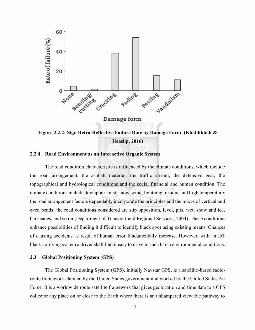
2.2.3 Traffic Signs Damage
Road traffic signs include black spot signs; damage to these signs is amongst the big
challenges that road users’ encounter. The damages are categorized into six groups that is
bending/cutting, cracking, vandalism, peeling and fading. Bending can be as result of strong
winds or when hit by a vehicle. Vandalism can result from deliberate action by human beings
(Khalilikhah & Heaslip, 2016) as depicted in Figure 2.2.1.
Figure 2.2.1 Traffic Sign Damage (Heaslip & Khalilikhah, 2016)
The damage to traffic signs brings about safety concerns to drivers and other road users.
Therefore, other measures such using GPS based IoT systems need to replace the conventional
methods. The damage to these signs affected the signs retro reflective characteristic, which made
it difficult for drivers to use them especially at night and foggy days. Figure 2.2.2 shows retro
reflective failure rate by damage of the road signs.
7
Figure 2.2.2: Sign Retro-Reflective Failure Rate by Damage Form (Khalilikhah &
Heaslip, 2016)
2.2.4 Road Environment as an Interactive Organic System
The road condition characteristic is influenced by the climate conditions, which include
the road arrangement, the asphalt material, the traffic stream, the defensive gear, the
topographical and hydrological conditions and the social financial and human condition. The
climate conditions include downpour, mist, snow, wind, lightning, residue and high temperature;
the road arrangement factors dependably incorporate the principles and the mixes of vertical and
even bends; the road conditions considered are slip opposition, level, pits, wet, snow and ice,
barricades, and so on (Department of Transport and Regional Services, 2004). These conditions
enhance possibilities of finding it difficult to identify black spot using existing means. Chances
of causing accidents as result of human error fundamentally increase. However, with an IoT
black notifying system a driver shall find it easy to drive in such harsh environmental conditions.
Global Positioning System (GPS)
The Global Positioning System (GPS), initially Navstar GPS, is a satellite-based radio-
route framework claimed by the United States government and worked by the United States Air
Force. It is a worldwide route satellite framework that gives geolocation and time data to a GPS
collector any place on or close to the Earth where there is an unhampered viewable pathway to

8
at least four GPS satellites. Obstacles, for example, mountains and structures obstruct the
moderately feeble GPS signals (Vandana, 2003; Hamilton-Baillie & Jones, 2005).
The GPS does not require the user to transmit any information, and it works
autonomously of any telephonic or web gathering. However, these innovations can improve the
helpfulness of the GPS situating data. The GPS gives basic situating capacities to military,
common, and business clients around the globe. The United States government made the
framework, looks after it, and makes it freely accessible to anybody with a GPS receiver
(Westbrook & Richharia, 2010). The GPS utilizes satellites to transmit exact microwave signals.
The cell phones with GPS recipients infer the present area, time, and speed of the gadget from
the signs (Dana, 1996). GPS has three primary parts: Absolute area; decides the area of the client,
Relative development; helpful in applications identified with Seismology and Astronomical
Sciences, Time exchange - clock synchronization that empowers time exchange. These parts
decide the present position of the client dependent on the accompanying components: Cellular
ID, Longitude and Latitude.
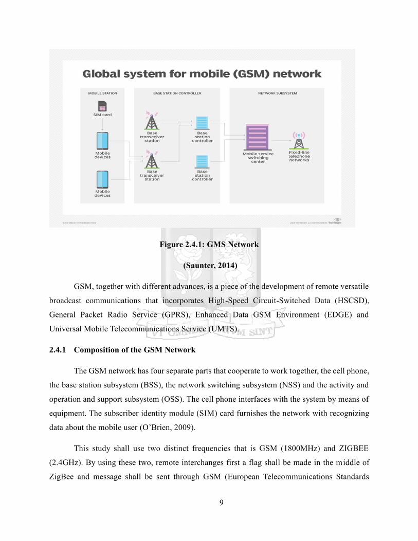
Global System for Mobile Communications (GSM)
GSM (Global System for Mobile correspondence) is an advanced versatile system that is
broadly utilized by cell phone clients all over the world. According to O’Brien (2009), GSM
utilizes a variety of time division different access (TDMA) and is the most broadly utilized of
the three computerized remote communication advancements: TDMA, GSM and code-division
numerous entrance (CDMA). GSM digitizes and packs information, at that point sends it down
a channel with two different surges of client information, each voluntarily space. It works at
either the 900-megahertz (MHz) or 1,800 MHz recurrence band (Sauter, 2014; Huurdeman,
2003). Figure 2.4.1 shows integrated GSM components.
9
Figure 2.4.1: GMS Network
(Saunter, 2014)
GSM, together with different advances, is a piece of the development of remote versatile
broadcast communications that incorporates High-Speed Circuit-Switched Data (HSCSD),
General Packet Radio Service (GPRS), Enhanced Data GSM Environment (EDGE) and
Universal Mobile Telecommunications Service (UMTS).
2.4.1 Composition of the GSM Network
The GSM network has four separate parts that cooperate to work together, the cell phone,
the base station subsystem (BSS), the network switching subsystem (NSS) and the activity and
operation and support subsystem (OSS). The cell phone interfaces with the system by means of
equipment. The subscriber identity module (SIM) card furnishes the network with recognizing
data about the mobile user (O’Brien, 2009).
This study shall use two distinct frequencies that is GSM (1800MHz) and ZIGBEE
(2.4GHz). By using these two, remote interchanges first a flag shall be made in the middle of
ZigBee and message shall be sent through GSM (European Telecommunications Standards
10
Institute, 2011). There shall be two sheets, one contains ZIGBEE and keypad and alternate
contains ZIGBEE and GSM. The primary board will be put at the black spot zones and the second
board will be put in the flag territory (Salgues, 1997; Teymourzadeh, Ahmed, Chan & Hoong,
2013).
The framework utilizes a conservative hardware worked around glimmer form of at
89s52 microcontroller with a non-unpredictable memory fit for holding the secret word
information for more than ten years. The client can alter the secret word. ISP is utilized to relay
the code into the microcontroller.
2.4.2 Existing Systems Technologies for Addressing Road Accidents
2.4.2.1 Accident Detection and Messaging System Using GSM and GPS
The main aim of the project Accident Detection and Messaging System is to inform the
Ambulance and Police of the accident site and arrange for necessary steps to control the situation.
This system is not only efficient but also worthy to be implemented. The Accident Detection and
Messaging System can be fitted in the vehicle (Ambulance or the Police) and they get informed
about any untoward incident at the go (Russell & Hasik, 2002).
Accident Detection and Messaging System execution is simple; the system makes use of
GSM and GPS technologies. GPS is used for taking the coordinates of the site of the accident
while GSM is used for sending the coordinates to cell phones. To make this process all the
controls are made using Arduino whereas an LCD is used to display the coordinates. Figure 2.4.2
shows accident detection and messaging system schematic diagram.

11
Figure 2.4.2: Accident Detection and Messaging System Schematic Diagram
The Vibration Sensor recognizes the mishap and thusly sends the signs to Arduino. Now
the Arduino takes control and begins gathering the directions got from the GPS, which are later
sent to the Central Emergency Monitoring Station by utilizing the GSM Module (Dana, 2005;
Castrejon-Pita, Baxter, Morgan, Temple & Martin, 2013).
In this study, the GPS Module is used to help in the recognition of black spots, by availing
the co-ordinates of the black spot to the microcontroller. GPS satellites circle the earth two times
per day in an exact circle and transmit flag data to earth. GPS recipients take this data and use
triangulation to figure the client's accurate area. Basically, the GPS collector looks at the time a
flag was transmitted by a satellite with the time it was gotten. The time contrast tells the GPS
beneficiary how far away the satellite is. Presently, with separation estimations from a couple of
more satellites, the beneficiary can decide the client's position and show it on the unit's electronic
guide. GPS can compute the longitude and scope of areas and transmit this data to a collector,
which helps the individual utilizing GPS to accurately find the coordinates. GPS gadgets have been
fabricated into some vehicle models and are likewise accessible as remain solitary gadgets
(Rumerman, 2009).
The blackspot position is normally definitely known and that area consolidated into the
framework. Thus, when a driver is moving toward this point, he/she is sent an audio SMS to
12
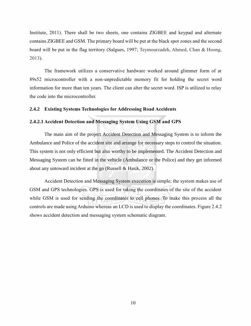
caution him/her that they are moving toward a black spot. This will make them progressively
mindful and consequently enables the driver around safely. Figure 2.4.3 shows Arduino module.
Figure 2.4.3: Arduino UNO (Rumerman, 2009)
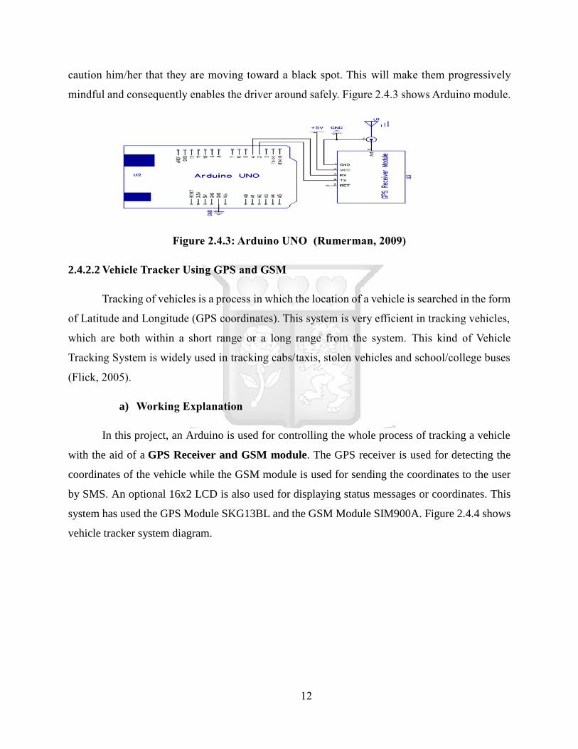
2.4.2.2 Vehicle Tracker Using GPS and GSM
Tracking of vehicles is a process in which the location of a vehicle is searched in the form
of Latitude and Longitude (GPS coordinates). This system is very efficient in tracking vehicles,
which are both within a short range or a long range from the system. This kind of Vehicle
Tracking System is widely used in tracking cabs/taxis, stolen vehicles and school/college buses
(Flick, 2005).
a) Working Explanation
In this project, an Arduino is used for controlling the whole process of tracking a vehicle
with the aid of a GPS Receiver and GSM module. The GPS receiver is used for detecting the
coordinates of the vehicle while the GSM module is used for sending the coordinates to the user
by SMS. An optional 16x2 LCD is also used for displaying status messages or coordinates. This
system has used the GPS Module SKG13BL and the GSM Module SIM900A. Figure 2.4.4 shows
vehicle tracker system diagram.
13
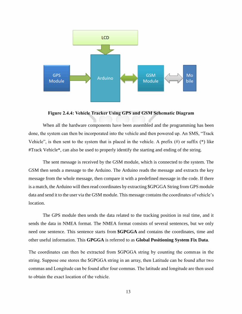
Figure 2.4.4: Vehicle Tracker Using GPS and GSM Schematic Diagram
When all the hardware components have been assembled and the programming has been
done, the system can then be incorporated into the vehicle and then powered up. An SMS, “Track
Vehicle”, is then sent to the system that is placed in the vehicle. A prefix (#) or suffix (*) like
#Track Vehicle*, can also be used to properly identify the starting and ending of the string.
The sent message is received by the GSM module, which is connected to the system. The
GSM then sends a message to the Arduino. The Arduino reads the message and extracts the key
message from the whole message, then compare it with a predefined message in the code. If there
is a match, the Arduino will then read coordinates by extracting $GPGGA String from GPS module
data and send it to the user via the GSM module. This message contains the coordinates of vehicle’s
location.
The GPS module then sends the data related to the tracking position in real time, and it
sends the data in NMEA format. The NMEA format consists of several sentences, but we only
need one sentence. This sentence starts from $GPGGA and contains the coordinates, time and
other useful information. This GPGGA is referred to as Global Positioning System Fix Data.
The coordinates can then be extracted from $GPGGA string by counting the commas in the
string. Suppose one stores the $GPGGA string in an array, then Latitude can be found after two
commas and Longitude can be found after four commas. The latitude and longitude are then used
to obtain the exact location of the vehicle.

14
Conceptual Framework
Based on the literature reviewed telecommunication provides possibility to develop a
GPS based IoT to identify black spots for drivers. This study proposes the following conceptual
framework to realize the objectives of this project. Figure 2.5.1 shows the conceptual framework
of this research.
The GPS module shall be responsible for locating the coordinates from road sections
designated as black spots. It shall then provide this information to the microcontroller, which
processes it. The microcontroller will trigger the GSM to send appropriate message to the driver.
Driver GSM
Microcontroller
GPS
Figure 2.5.1: GPS based IoT System Conceptual Framework

15
Chapter Three
Methodology
Introduction
This chapter outlines the research methods used in the study. It provides information
about the participants that is the inclusion criteria in the study, participants under study and how
they were sampled. The researcher describes the research design selected for this study and the
reasons for the selection. The tools utilized for information gathering are also outlined and the
techniques that were pursued to realize study. Finally, the moral issues that were followed in the
process are additionally talked about.
Research Design
Research design outlines the methods for doing research, including when, and under what
conditions the information should be obtained. This is to indicate an arrangement for creating
observational proof that should be utilized to respond to the research questions. The structure of
the research characterizes the research type, speculations, autonomous and subordinate factors,
test structure, information gathering techniques and a factual examination plan (Lohr, 2004).
This study took an experimental approach that involves gathering of arbitrary
coordinates, which denote and represent black spots. The study is then validated by creating an
IoT GPS based system for testing coordinates identified to represent black spots. The built IoT
system is a proof of concept under study and tends to be as objective as possible by using
coordinates from different locations.
Location of the Study
The Kenyan highways were selected to be location for testing this study. One of them
being the notorious black spot on the Nakuru-Eldoret roadway, around 27 kilometers from
Nakuru Town, Salgaa grew around 1994 with just two booths. The town gets its name from
Kipsigis words “Sal”, which implies commendation, and “Gaa” alluding to home. Along these
lines, Salgaa in Kalenjin implies adulating one's home. The GPS co-ordinates of Salgaa's
16
blackspot is (0.2048° S, 35.8479° E). Salgaa is a leading black spot in Kenya, if the quantity of
road accidents that have occurred along this point is anything to go by.
The 14 kilometer stretch on the Nakuru-Eldoret thruway has turned out to be synonymous
with grisly accidents that have terminated several lives throughout the years. Salgaa is drifting
for stunning news, and most explicitly that includes savage road accidents. It has turned into a
blackspot because of many accidents that have been happening at the same spot.
3.3.1 Target Population and Sampling
The drivers were chosen as respondents for interview questions under this study. The
questions aimed at getting requirements about the systems user requirements. This ensures
system built has the users’ expectations incorporated. Sampling was done in random manner
selecting personal car, public and institutional car drivers.
System Development Methodology
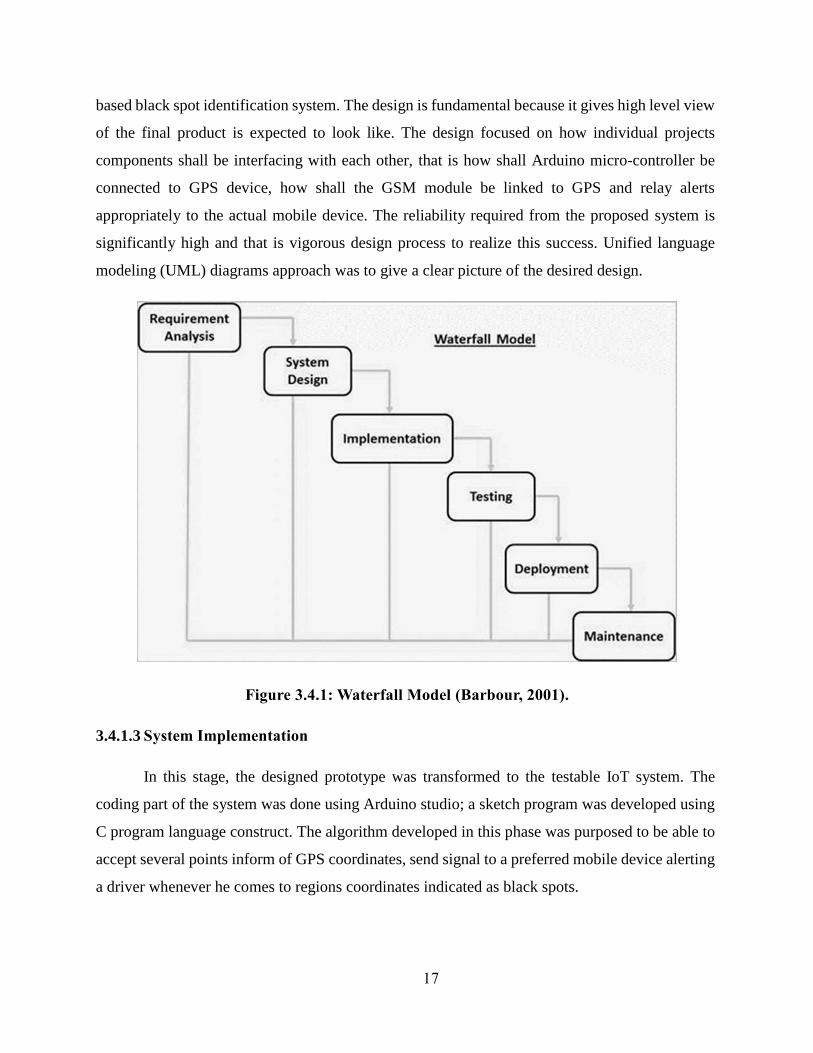
Waterfall model was chosen to implement the system under study. The waterfall model
is a generally direct successive structure approach for specific regions of building plan. In
programming advancement, it will in general be among the less iterative and adaptable
methodologies, as advancement streams in to a great extent one bearing ("downwards" like a
cascade) through the periods of origination, inception, investigation, plan, development, testing,
sending and support (Barbour, 2001).
3.4.1 Waterfall Model Phases
3.4.1.1 System Requirement Gathering and Analysis
The system requirements from the drivers were analyzed to form a basis in which the
GPS blackspot identification system shall be constructed. The drivers’ requirements helped in
component identification and prototype design.
3.4.1.2 System Design
The requirements were transformed to appropriate design in this phase. Each requirement
identified was modeled into a design construct that depicts individual components of an IoT GPS
17
based black spot identification system. The design is fundamental because it gives high level view
of the final product is expected to look like. The design focused on how individual projects
components shall be interfacing with each other, that is how shall Arduino micro-controller be
connected to GPS device, how shall the GSM module be linked to GPS and relay alerts
appropriately to the actual mobile device. The reliability required from the proposed system is
significantly high and that is vigorous design process to realize this success. Unified language
modeling (UML) diagrams approach was to give a clear picture of the desired design.
Figure 3.4.1: Waterfall Model (Barbour, 2001).
3.4.1.3 System Implementation
In this stage, the designed prototype was transformed to the testable IoT system. The
coding part of the system was done using Arduino studio; a sketch program was developed using
C program language construct. The algorithm developed in this phase was purposed to be able to
accept several points inform of GPS coordinates, send signal to a preferred mobile device alerting
a driver whenever he comes to regions coordinates indicated as black spots.
18
3.4.1.4 System Integration and Testing
All the project components; Arduino, GSM and GPS were integrated to form a complete
IoT system subsequent to testing of every unit. Testing was done using a moving car, which with
the IoT system installed. The mobile device was used to check whether the IoT system installed
in a moving car model was able to send the desired signals. The testing was done in iterative
manner to have all sampled coordinates to ascertain the reliability and robustness of the system.
3.4.1.5 Deployment of Framework
In an event that the system passes defined ethical and technical standard by the relevant
transport authority it shall be tried out in really moving vehicle along the location of the study.
This exercise is performed to ensure that the study is as objective as possible.
3.4.1.6 System Maintenance
This involves adding more features to the system already in use. It is about enhancing the
system performance for instance improving its security features, usability and reliability. The
system is software driven therefore, adding features is very easy by just adding program modules
to the existing program. Upon full acceptance of the system by the stakeholders, further
improvements shall be carried upon requests to enhance its usability and performance.
Maintenance is crucial because it addressed issues, which were never discovered in the testing
phase or add new features to the system.
3.4.2 Justification for Choosing the Waterfall Framework
The upsides of waterfall model are that it takes into consideration departmentalization and
control. A calendar can be set with due dates for each phase of improvement and an item can
continue through the advancement procedure demonstrate stages one by one. Improvement moves
from idea, through plan, usage, testing, establishment, investigating, and winds up at activity and
upkeep. Each period of advancement continues in strict request. The waterfall approach has the
following advantages; Simple and easy to understand and use, easy to manage due to the rigidity
of the model each phase has specific deliverables and a review process, Phases are processed and
completed one at a time, works well for smaller projects where requirements are (Creswell, 2014).
19
3.4.3 Research Quality
While research into quality relates to the logical procedure, proof quality relates more to
a judgment with respect to the quality and certainty one has in the examination discoveries
exuding from the logical procedure (Mosteller & Boruch, 2002). The study shall be tested using
coordinates from different locations; these points shall represent the black spot. The analysis shall
be done using the results obtained from these coordinates. Unit testing was also done during
development at the locations reachable by the researcher.
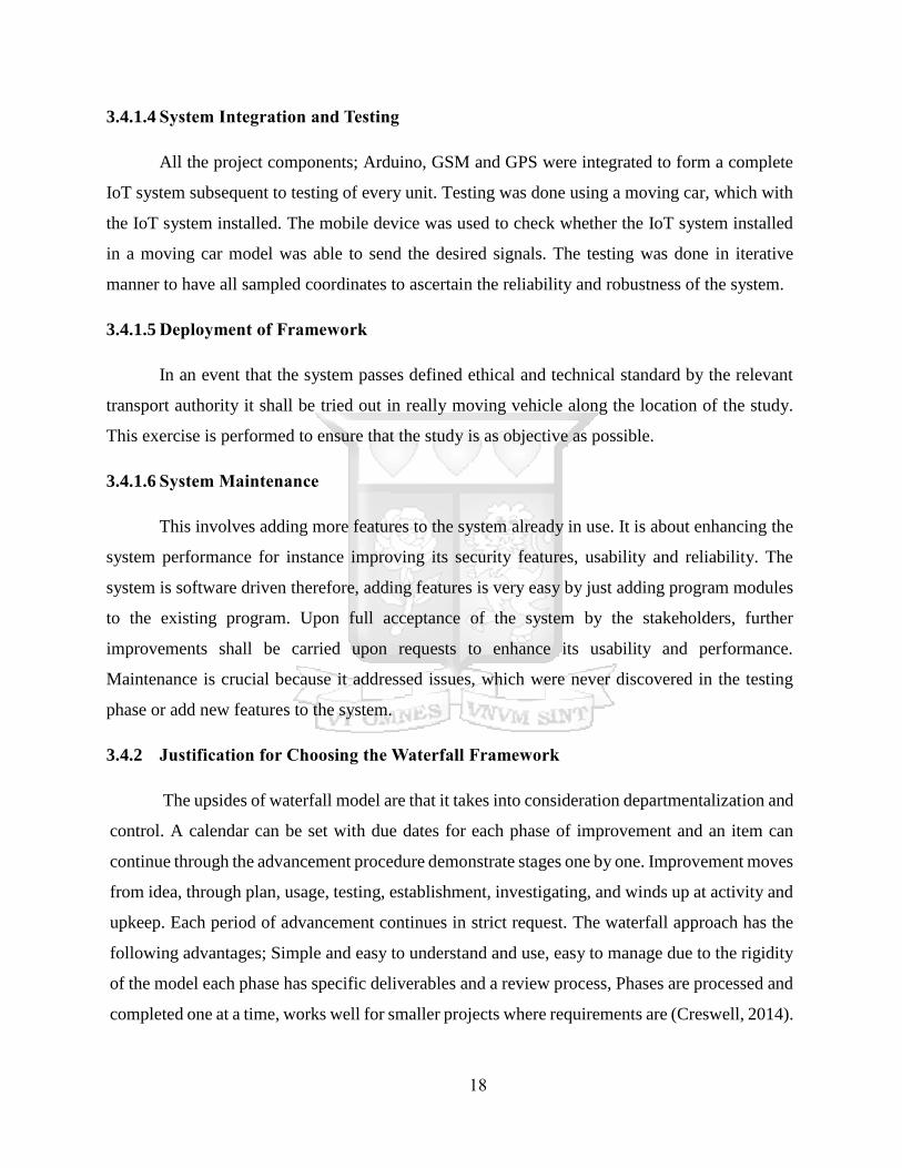
3.4.3.1 Evaluation Metrics
The IoT system developed is expected to convey correct results at every stage of its testing
for instance, when a driver is close to a black spot, when driver is at the actual black spot region
and when the driver is past this region. It is paramount to know the results of section under testing
for different points so that to give right judgment pertaining to system reliability. Table 3.4.1 was
to be used to record the outcome prior to its analysis.
Table 3.4.1 Test Results Template
Number
of
Locations
Coordinates
before
black spot
zone
Result
1
Coordinates
range of
black spot
region
Result
2
Coordinates
range after
black spot
region
Result
3
Outcome
score
1
2
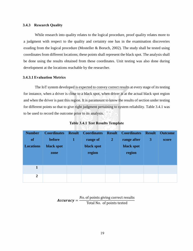
𝑨𝒄𝒄𝒖𝒓𝒂𝒄𝒚 =𝑁o. of points giving correct results
Total No. of points tested
20
The higher the accuracy scores the high the system reliability. The desired outcome is that
all the point under testing give the correct responsive to ensure to guarantee that system will
perform well after deployment.
3.4.3.2 Evaluation of System Components
GSM for instant is known to perform well in the telecommunication companies. GSM is
used to relay information between two communicating mobile devices using 2G Internet band.
The use of GSM in this study shall tremendously boost the functionality of the system due to its
proven performance. On the hand GPS has also been used in the other fields such tracking devices,
given that it is satellite technology its performance and reliability concerns are super excellent;
there many of application using currently GPS such as Google maps and car tracking devices.
Ethical Considerations
3.5.1 Informed Consent
Informed consent seeks to incorporate the rights of autonomous individuals through self-
determination. It also seeks to prevent assaults on the integrity of the patient and protect personal
liberty and veracity.
This study, to a large extent has observed informed consent by allowing all participants
to give their honest views. The interview question provided was clear and some even allowed
the interviewees to speak their own mind even outside the interview questions. This was done to
ensure that the system does not limit user understanding of the system. It is also a good way to
unlock the concepts not previously covered by the study.
21
Chapter Four
System Analysis and Design
Introduction
Software architecture is the process of determining a well-defined solution that complies
with all the operational and technical requirements and on the other hand improves such common
quality attributes as security, accessibility and performance. Software design is the process of
applying software solutions to one or more set of problems (Hay, 2003).
The study involves notifying drivers when they encounter black spots, the major goal of
application architecture is to analyze functional and technical requirement, understand use cases
and prepare the ways to apply those use cases in software. Good architecture determines requests
that affect an application structure and, due to its flexibility, lessens business risks related to the
development of technical solution. Apart from that, software architecture deals with quality and
functional requirement; realizes use-cases and scenarios and exposes the system structure while
hiding the underlying details (Laplante, 2009).
Requirements Analysis
In software engineering, requirements analysis encompasses those tasks that go into
determining the needs or conditions to meet for a new or altered product or project, taking
account of the possibly conflicting requirements of the various stakeholders, analyzing,
documenting, validating and managing software or system requirements (McConnell, 1996).
Requirements analysis is critical to the success or failure of a systems or software project.
The requirements should be documented, actionable, measurable, testable, traceable,
related to identified business needs or opportunities, and defined to a level of detail enough for
system design. A functional requirement describes what a software system should do, while non-
functional requirements place constraints on how the system will do so (Nusseibeh &
Easterbrook, 2000). The system should be able to detect a black spot at some predefined distance
and alert a driver using audio message as opposed to text message.
22
4.2.1 Functional Requirements
i. The system should be able to locate the black spot at a distance via Global Positioning
System (GPS).
ii. With the aid of the incorporated Global System for Mobile communication (GSM) in the
system, an SMS should be sent to the driver approaching a black spot, which should be
converted, to audio by the mobile device.
iii. The system should notify a driver when they are approaching a black spot via audio.
iv. The system should caution a driver when they get to the black spot.
v. The system should advice the driver on how to drive safely through the black spot to
avoid accidents.
vi. The system should inform a driver when he/she has driven out of the danger zone, and
tell them that they drove through the black spot safely.
4.2.2 Non-Functional Requirements
i. The driver should be notified that they are approaching a black spot when they are 150
meters from the black spot.
ii. An SMS audio is to be sent to the driver of the vehicle approaching the black spot through
the phone number of their registered SIM card.
iii. The guidelines that the system gives the driver should be accurate so as not to mislead
the driver into danger
System Architecture
The system architecture shows the general layout of the black spot audio notification
system and the components it is made up of as illustrated in the Figures 4.3.1. The black spot
audio notification process begins when a driver is approaching a black spot and is within a radius
of 150 meters of it. This is with the aid of the Global Positioning System (GPS). The Global
System for Mobile Communication (GSM) is then triggered.
When the GSM is triggered, it sends an audio SMS to the driver alerting them that they
are approaching a black spot and gives them some guidelines on safe driving through the black
spot. This should help reduce black spot related accidents. When the driver drives out of the

23
black spot, the system should inform them that they are safe. This should help motivate and
increase the drivers’ confidence.
Figure 4.3.1: High-level Architecture of a GPS-based IoT System for Black Spot
Notifications
4.3.1 Scalability
This proposed solution is highly scalable in that; it can be used to guide drivers driving
at night or during unfavorable weather where viewing road signs might be challenging.
Therefore, the drivers can be guided about traffic situation by the audio notification system. The
proposed solution can also be adopted to notify road users of other dangerous road sections like
sharp bends. This can be achieved by extending the code to include this scenario. The notification
messages can be scaled introducing parameters in a separate entity for each scenario and even
customized the audio to the desired language of the drivers thus eliminating the possibility of
language barrier. The advanced version of this proposed solution can be integrated to the vehicle
dashboard system so that it assumes a good abstraction as possible.
24
4.3.2 Data Storage
The system should provide data storage to store the geographical location of the car
during the time of notification when the driver is approaching the black spot, when he/she is
driving through the black spot and when he/she is out of the black spot. In the event of a black
spot related accident, the information stored is analyzed and conclusions that are made are to be
used to better the system and utilized to reduce black spot related accidents.
4.3.3 Usability
The intended users of this system are drivers driving through black spots. This black spot
audio notification system is user friendly in that the SMS that the driver receives on approaching
a black spot is an audio and not text, which highly reduces the chances of an accident. In addition
to that, the system also advises the driver on how to safely drive through a black spot making it
even more user friendly.
Use Case Diagram
A use case diagram at its simplest is a representation of a user's interaction with the
system that shows the relationship between the user and the different use cases in which the user
is involved (Stellman & Greene, 2005). A use case diagram can identify the different types of
users of a system and the different use cases and will often be accompanied by other types of
diagrams as well. The primary user of the system under study is a driver. The driver interacts
with upper layer of the system that relays notification to him/her.
The GPS system reads and matches predefined black spot coordinates from the section
of the road. The GPS then relays this information to the micro controller in our case Arduino
Uno for processing. Once this information is processed the micro controller prepares correct
message to be sent to the user. The GSM module is activated to send this information to the
mobile device from which the user gets notified via appropriate mode.
There should be also a system to log all information from GSM for future analysis. For
instance, if the diver was given the right notification and still caused the accident at this point,
what can be ruled out? The logs can also facility further improvements to the system.
25
Figure 4.4.1: Use Case Diagram
4.4.1 Detailed Case Descriptions
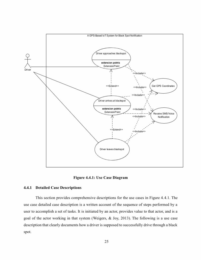
This section provides comprehensive descriptions for the use cases in Figure 4.4.1. The
use case detailed case description is a written account of the sequence of steps performed by a
user to accomplish a set of tasks. It is initiated by an actor, provides value to that actor, and is a
goal of the actor working in that system (Weigers, & Joy, 2013). The following is a use case
description that clearly documents how a driver is supposed to successfully drive through a black
spot.
26
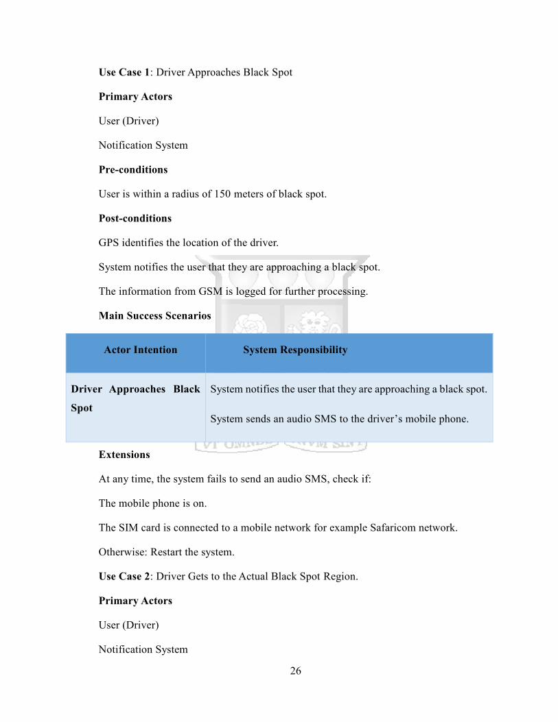
Use Case 1: Driver Approaches Black Spot
Primary Actors
User (Driver)
Notification System
Pre-conditions
User is within a radius of 150 meters of black spot.
Post-conditions
GPS identifies the location of the driver.
System notifies the user that they are approaching a black spot.
The information from GSM is logged for further processing.
Main Success Scenarios
Actor Intention System Responsibility
Driver Approaches Black
Spot
System notifies the user that they are approaching a black spot.
System sends an audio SMS to the driver’s mobile phone.
Extensions
At any time, the system fails to send an audio SMS, check if:
The mobile phone is on.
The SIM card is connected to a mobile network for example Safaricom network.
Otherwise: Restart the system.
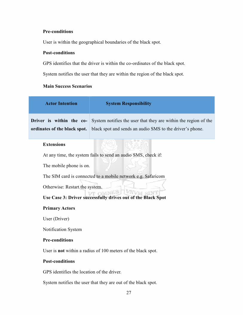
Use Case 2: Driver Gets to the Actual Black Spot Region.
Primary Actors
User (Driver)
Notification System
27
Pre-conditions
User is within the geographical boundaries of the black spot.
Post-conditions
GPS identifies that the driver is within the co-ordinates of the black spot.
System notifies the user that they are within the region of the black spot.
Main Success Scenarios
Actor Intention System Responsibility
Driver is within the co-
ordinates of the black spot.
System notifies the user that they are within the region of the
black spot and sends an audio SMS to the driver’s phone.
Extensions
At any time, the system fails to send an audio SMS, check if:
The mobile phone is on.
The SIM card is connected to a mobile network e.g. Safaricom
Otherwise: Restart the system.
Use Case 3: Driver successfully drives out of the Black Spot
Primary Actors
User (Driver)
Notification System
Pre-conditions
User is not within a radius of 100 meters of the black spot.
Post-conditions
GPS identifies the location of the driver.
System notifies the user that they are out of the black spot.
28
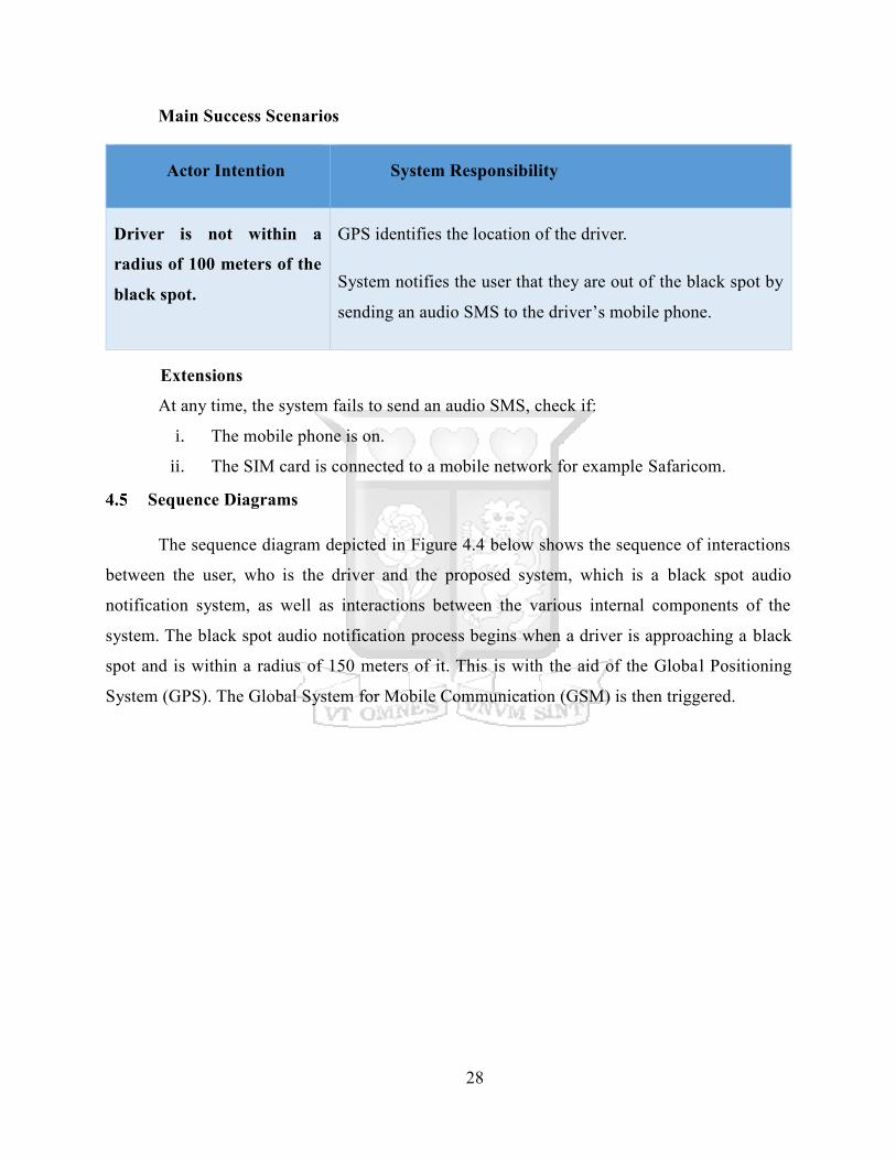
Main Success Scenarios
Actor Intention System Responsibility
Driver is not within a
radius of 100 meters of the
black spot.
GPS identifies the location of the driver.
System notifies the user that they are out of the black spot by
sending an audio SMS to the driver’s mobile phone.
Extensions
At any time, the system fails to send an audio SMS, check if:
i. The mobile phone is on.
ii. The SIM card is connected to a mobile network for example Safaricom.
Sequence Diagrams
The sequence diagram depicted in Figure 4.4 below shows the sequence of interactions
between the user, who is the driver and the proposed system, which is a black spot audio
notification system, as well as interactions between the various internal components of the
system. The black spot audio notification process begins when a driver is approaching a black
spot and is within a radius of 150 meters of it. This is with the aid of the Global Positioning
System (GPS). The Global System for Mobile Communication (GSM) is then triggered.
29
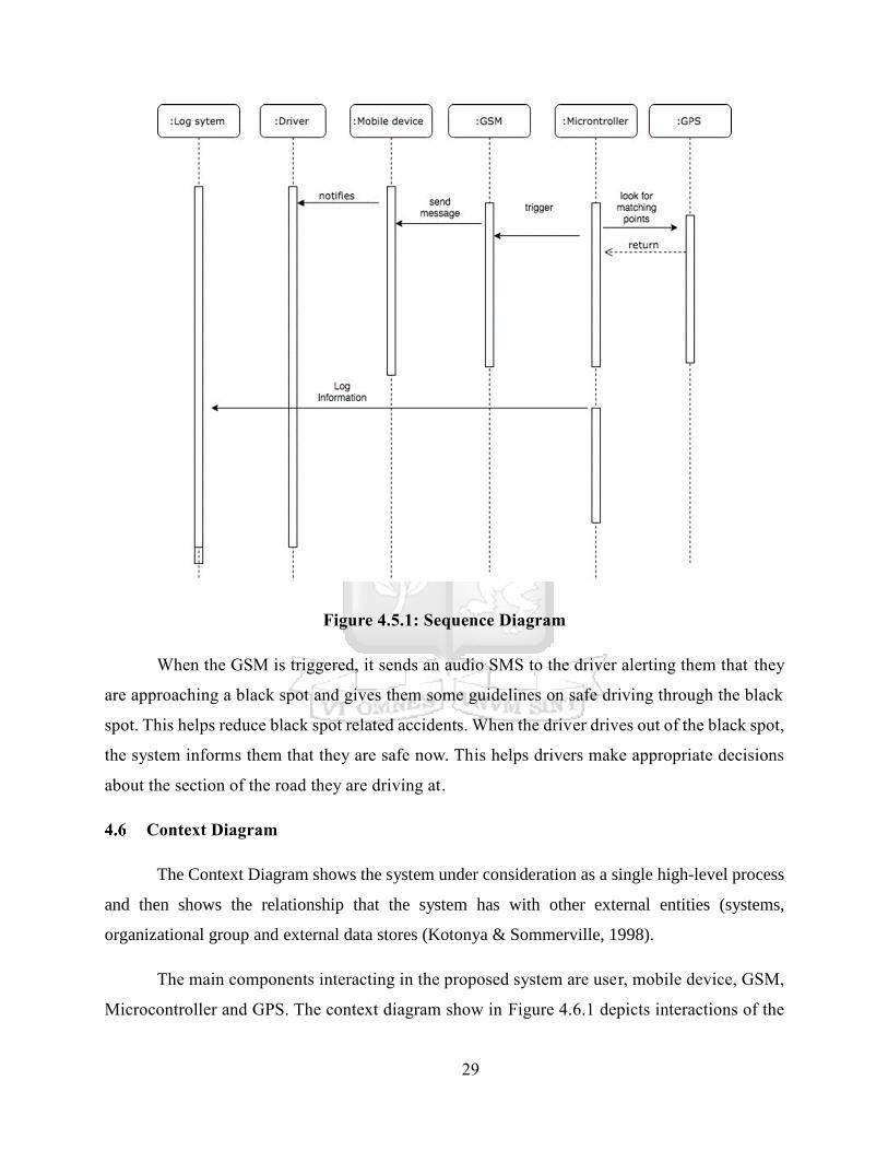
Figure 4.5.1: Sequence Diagram
When the GSM is triggered, it sends an audio SMS to the driver alerting them that they
are approaching a black spot and gives them some guidelines on safe driving through the black
spot. This helps reduce black spot related accidents. When the driver drives out of the black spot,
the system informs them that they are safe now. This helps drivers make appropriate decisions
about the section of the road they are driving at.
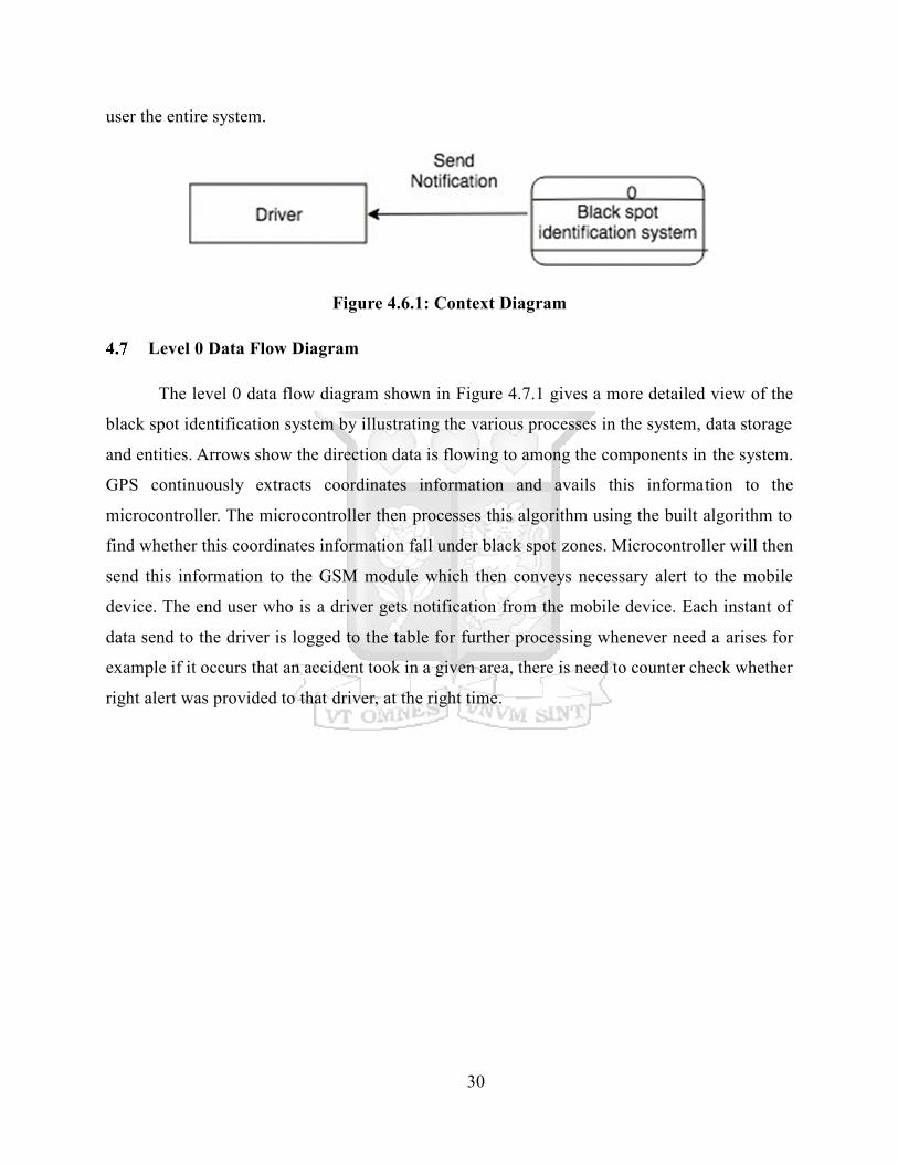
Context Diagram
The Context Diagram shows the system under consideration as a single high-level process
and then shows the relationship that the system has with other external entities (systems,
organizational group and external data stores (Kotonya & Sommerville, 1998).
The main components interacting in the proposed system are user, mobile device, GSM,
Microcontroller and GPS. The context diagram show in Figure 4.6.1 depicts interactions of the
30
user the entire system.
Figure 4.6.1: Context Diagram
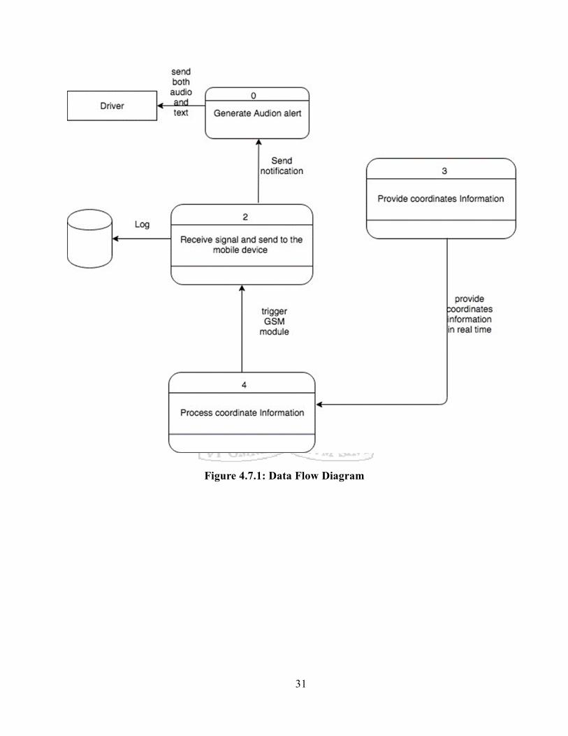
Level 0 Data Flow Diagram
The level 0 data flow diagram shown in Figure 4.7.1 gives a more detailed view of the
black spot identification system by illustrating the various processes in the system, data storage
and entities. Arrows show the direction data is flowing to among the components in the system.
GPS continuously extracts coordinates information and avails this information to the
microcontroller. The microcontroller then processes this algorithm using the built algorithm to
find whether this coordinates information fall under black spot zones. Microcontroller will then
send this information to the GSM module which then conveys necessary alert to the mobile
device. The end user who is a driver gets notification from the mobile device. Each instant of
data send to the driver is logged to the table for further processing whenever need a arises for
example if it occurs that an accident took in a given area, there is need to counter check whether
right alert was provided to that driver, at the right time.
31
Figure 4.7.1: Data Flow Diagram

32
Chapter Five
System Implementation and Testing
Introduction
This chapter describes how the system was implemented, tested and validated. System
implementation is a realization of a technical specification or algorithm as a program, software
component, or other computer system through computer programming and deployment. Many
implementations may exist for a given specification or standard (African Development Bank,
2013). System Testing is a level of software testing where complete and integrated software is
tested. The purpose of this test is to evaluate the system's compliance with the specified
requirements. In the system testing what is concentrated on is finding bugs/defects on integrated
modules. However, in the Software System Testing, what is concentrated on is finding
bugs/defects based on software application behavior, software design and expectations of the
end user.
Identifying Test Blackspots
A black spot is a place on a road that is considered to be dangerous because several
accidents have happened there. The project focuses on three major black spots in Kenya.
According to research conducted by the National Transport and Safety Authority (NTSA), Rift
Valley has 12 black spots, the greatest number, while North Eastern has the least at five (Ministry
of Transport-Kenya, 2005). In Nairobi County, Mombasa Road is the top killer, statistics by the
National Transport Safety Authority (NTSA) show. Between January and December 1, 2015,
Mombasa Road recorded 59 fatalities out of 628 deaths in Nairobi County. The killer spots have
been mapped out to warn motorists, pedestrians and cyclists to approach the areas with caution,
especially during the festive season when there is a lot of traffic on the roads. According to
NTSA, some 2,905 people have died on the roads between January and December 17 this year.
5.2.1 Salgaa Black Spot – Nakuru County
This black spot is a 14-kilometer stretch on the Nakuru-Eldoret highway. The 14-kilometer
stretch on the Nakuru-Eldoret highway has become synonymous with gruesome accidents that
33
have claimed hundreds of lives over the years. Police and the National Transport and Safety
Authority have blamed most of the accidents on speeding, careless overtaking and
freewheeling, especially by truck drivers. The accidents have robbed dozens of families of their
loved ones and left tens of others with injuries. NTSA is considering building a dual carriageway
between Salgaa and Sachangwan to minimize the accidents, which are mainly head-on collisions.
5.2.2 Mombasa Road between Bellevue to Cabanas – Nairobi County
In Nairobi County, Mombasa Road is the top killer, statistics by the National Transport
Safety Authority (NTSA) show. Between January and December 1, 2015, Mombasa Road
recorded 59 fatalities out of 628 deaths in Nairobi County. Mombasa Road is a deadly black spot
that has claimed so many lives over the past decade and that is why I chose it as a test black spot
area for this project.
5.2.3 Tsavo – Maungu – Voi Road Section – Coast Region
In the Coast Region, the Tsavo – Maungu – Voi Road Section is the top killer. This is in
accordance to the National Transport Safety Authority (NTSA) statistics. Latest statistics
available at the Traffic Headquarters in Nairobi indicate that 274 people were killed in accidents
as people travelled to various destinations to celebrate (European Commission, 2007). They
include 248 killed last December and 26 who have lost their lives since January as official
statistics show. This road section is a deadly black spot that has claimed so many lives over the
past decade and that is why it was chosen as one of the test black spot area for this project.
System Implementation
5.3.1 Required Components
a) Arduino
b) GSM Module
c) GPS Module
d) 16x2 LCD
e) Power Supply
f) Connecting Wires

34
5.3.2 System Working Explanation
GPS stands for Global Positioning System and used to detect the Latitude and Longitude
of any location on the Earth, with exact UTC time (Universal Time Coordinated). GPS module
is the main component in our vehicle tracking system project. This device receives the
coordinates from the satellite for each second, with time and date.
GPS module sends the data related to tracking position in real time, and it sends so many
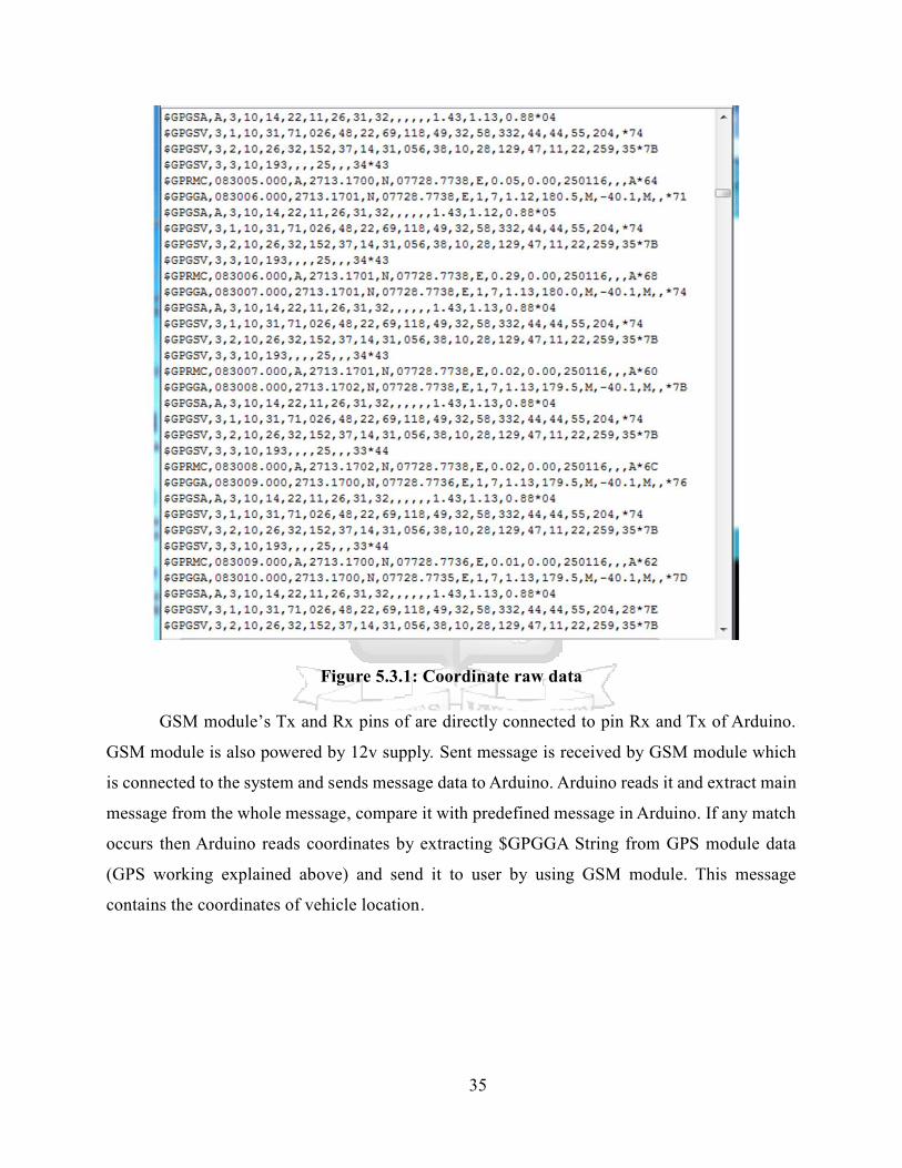
data in NMEA format (see the screenshot below). NMEA format consist several sentences, in
which we only need one sentence. This sentence starts from $GPGGA and contains the
coordinates, time and other useful information. This GPGGA is referred to Global Positioning
System Fix Data.
Coordinates can be extracted from $GPGGA string by counting the commas in the string.
Suppose you find $GPGGA string and stores it in an array, then Latitude can be found after two
commas and Longitude can be found after four commas. Now these latitude and longitude can
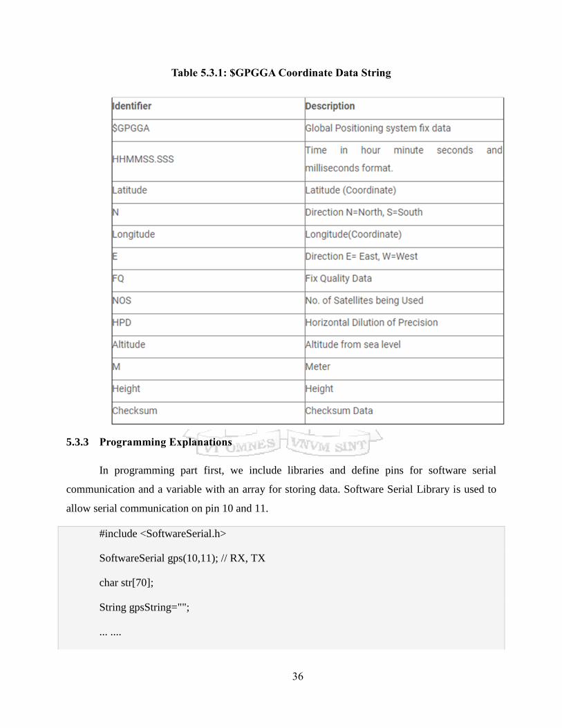
be put in other arrays. Table 5.3.1 presents the $GPGGA String, along with its description:
$GPGGA,104534.000,7791.0381, N,06727.4434, E,1,08,0.9,510.4, M,43.9, M, *47
$GPGGA,HHMMSS.SSS,latitude,N,longitude,E,FQ,NOS,HDP,altitude,M,height,M,,checksum
data.
35
Figure 5.3.1: Coordinate raw data
GSM module’s Tx and Rx pins of are directly connected to pin Rx and Tx of Arduino.
GSM module is also powered by 12v supply. Sent message is received by GSM module which
is connected to the system and sends message data to Arduino. Arduino reads it and extract main
message from the whole message, compare it with predefined message in Arduino. If any match
occurs then Arduino reads coordinates by extracting $GPGGA String from GPS module data
(GPS working explained above) and send it to user by using GSM module. This message
contains the coordinates of vehicle location.
36
Table 5.3.1: $GPGGA Coordinate Data String
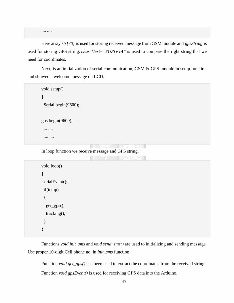
5.3.3 Programming Explanations
In programming part first, we include libraries and define pins for software serial
communication and a variable with an array for storing data. Software Serial Library is used to
allow serial communication on pin 10 and 11.
#include <SoftwareSerial.h>
SoftwareSerial gps(10,11); // RX, TX
char str[70];
String gpsString="";
... ....
37
.... ....
Here array str[70] is used for storing received message from GSM module and gpsString is
used for storing GPS string. char *test=”$GPGGA” is used to compare the right string that we
need for coordinates.
Next, is an initialization of serial communication, GSM & GPS module in setup function
and showed a welcome message on LCD.
void setup()
{
Serial.begin(9600);
gps.begin(9600);
... ....
.... ....
In loop function we receive message and GPS string.
void loop()
{
serialEvent();
if(temp)
{
get_gps();
tracking();
}
}
Functions void init_sms and void send_sms() are used to initializing and sending message.
Use proper 10-digit Cell phone no, in init_sms function.
Function void get_gps() has been used to extract the coordinates from the received string.
Function void gpsEvent() is used for receiving GPS data into the Arduino.
38
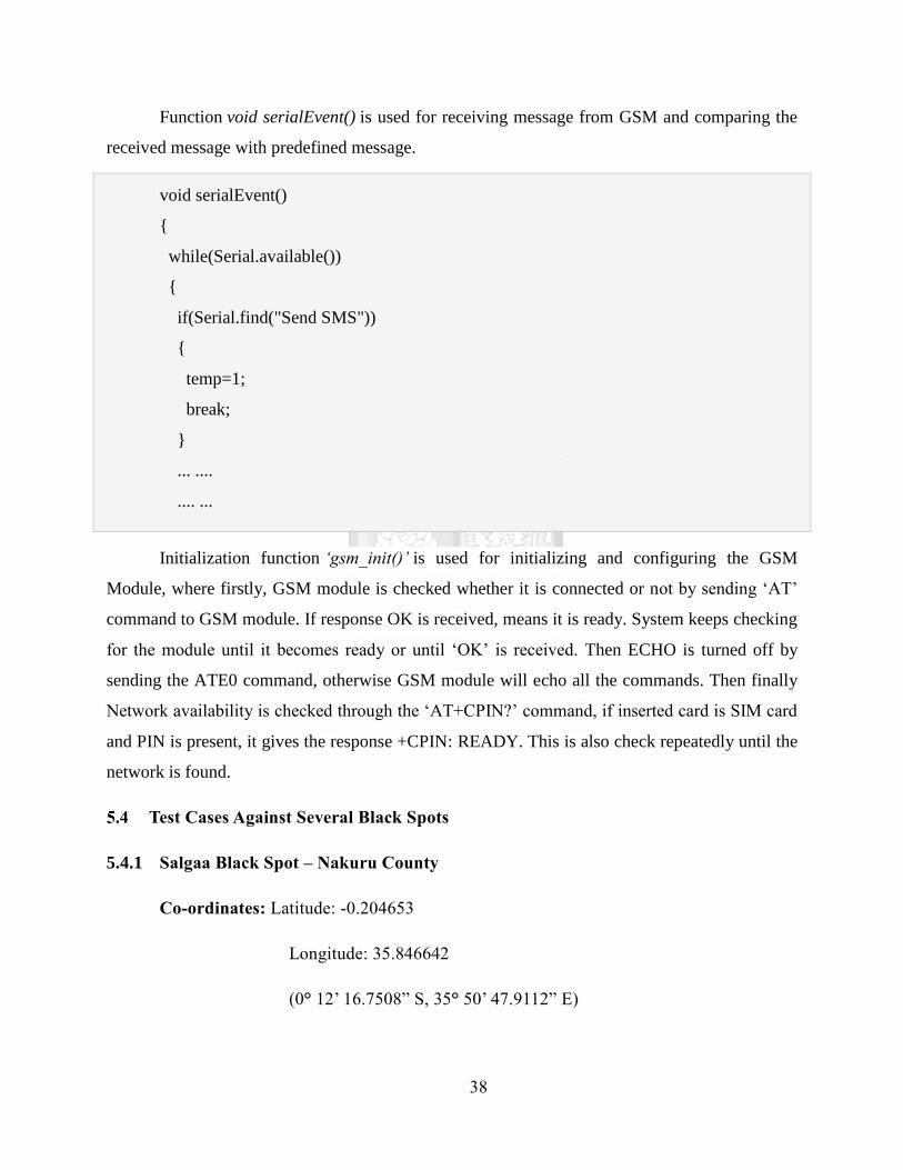
Function void serialEvent() is used for receiving message from GSM and comparing the
received message with predefined message.
void serialEvent()
{
while(Serial.available())
{
if(Serial.find("Send SMS"))
{
temp=1;
break;
}
... ....
.... ...
Initialization function ‘gsm_init()’ is used for initializing and configuring the GSM
Module, where firstly, GSM module is checked whether it is connected or not by sending ‘AT’
command to GSM module. If response OK is received, means it is ready. System keeps checking
for the module until it becomes ready or until ‘OK’ is received. Then ECHO is turned off by
sending the ATE0 command, otherwise GSM module will echo all the commands. Then finally
Network availability is checked through the ‘AT+CPIN?’ command, if inserted card is SIM card
and PIN is present, it gives the response +CPIN: READY. This is also check repeatedly until the
network is found.
Test Cases Against Several Black Spots
5.4.1 Salgaa Black Spot – Nakuru County
Co-ordinates: Latitude: -0.204653
Longitude: 35.846642
(0° 12’ 16.7508” S, 35° 50’ 47.9112” E)

39
Table 5.4.1 shows an explanation of the tests that were conducted at the notorious Salgaa
Black Spot. The table also explains the expected action of the system from when a user is
approaching a black spot, to when the user gets to the black spot, until the point when the user
exits the black spot. The system is supposed to notify the user of the system by sending them an
audio SMS informing them of their proximity to the black spot and to give them guidelines on
how to safely drive through a black spot.
Table 5.4.1: Test Case One
Black Spot
Location
Black
Spot
Region
Action
Number
User Action Expected System
Action
Actual System
Action
Salgaa
Black Spot
Nakuru
County
1 Approaches
Black Spot
(Is within a
radius of
150m)
The system
should notify the
user by sending
an audio SMS that
they are
approaching a
Black Spot.
The system
should give the
user some
guidelines on how
to safely drive
through a black
spot.
The user was
notified on
approaching the
black spot.
The user received
guidelines on how
to safely drive
through the black
spot.
Salgaa
Black Spot
Nakuru
County
2 Gets to the
Black Spot
(Is within the
black spot
coordinates)
The system
should notify the
user that they
have entered the
region of the
black spot.
The user is notified
that they have
entered the black
spot region.
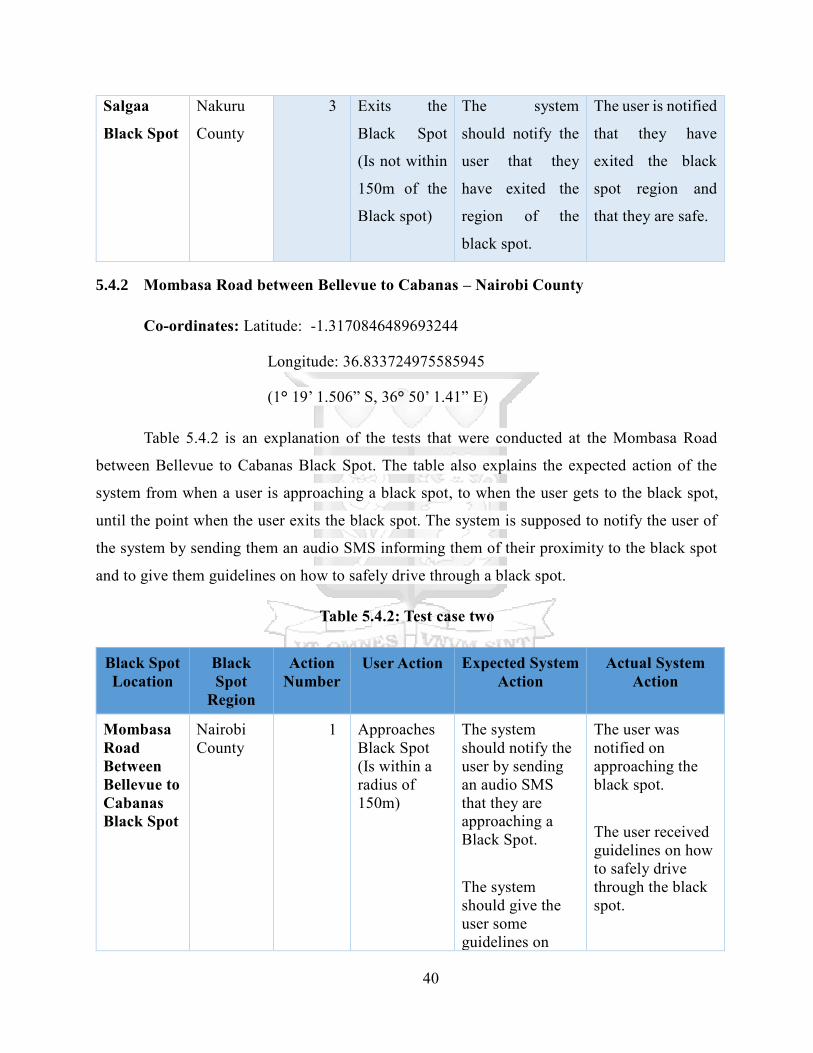
40
Salgaa
Black Spot
Nakuru
County
3 Exits the
Black Spot
(Is not within
150m of the
Black spot)
The system
should notify the
user that they
have exited the
region of the
black spot.
The user is notified
that they have
exited the black
spot region and
that they are safe.
5.4.2 Mombasa Road between Bellevue to Cabanas – Nairobi County
Co-ordinates: Latitude: -1.3170846489693244
Longitude: 36.833724975585945
(1° 19’ 1.506” S, 36° 50’ 1.41” E)
Table 5.4.2 is an explanation of the tests that were conducted at the Mombasa Road
between Bellevue to Cabanas Black Spot. The table also explains the expected action of the
system from when a user is approaching a black spot, to when the user gets to the black spot,
until the point when the user exits the black spot. The system is supposed to notify the user of
the system by sending them an audio SMS informing them of their proximity to the black spot
and to give them guidelines on how to safely drive through a black spot.
Table 5.4.2: Test case two
Black Spot
Location
Black
Spot
Region
Action
Number
User Action Expected System
Action
Actual System
Action
Mombasa
Road
Between
Bellevue to
Cabanas
Black Spot
Nairobi
County
1 Approaches
Black Spot
(Is within a
radius of
150m)
The system
should notify the
user by sending
an audio SMS
that they are
approaching a
Black Spot.
The system
should give the
user some
guidelines on
The user was
notified on
approaching the
black spot.
The user received
guidelines on how
to safely drive
through the black
spot.

41
how to safely
drive through a
black spot.
Mombasa
Road
Between
Bellevue to
Cabanas
Black Spot
Nairobi
County
2 Gets to the
Black Spot
(Is within the
black spot
coordinates)
The system
should notify the
user that they
have entered the
region of the
black spot.
The user is
notified that they
have entered the
black spot region.
Mombasa
Road
Between
Bellevue to
Cabanas
Black Spot
Nairobi
County
3 Exits the
Black Spot
(Is not within
150m of the
Black spot)
The system
should notify the
user that they
have exited the
region of the
black spot.
The user is
notified that they
have exited the
black spot region
and that they are
safe.
5.4.3 Tsavo – Maungu – Voi Road Section – Coast Region
Co-ordinates: Latitude: -3.339051
Longitude: 38.525666
(3° 20’ 20.5836” S, 38° 31’ 32.3976” E)
Table 5.4 is an explanation of the tests that were conducted at the Tsavo – Maungu – Voi
Road Section Black Spot. The table also explains the expected action of the system from when
a user is approaching a black spot, to when the user gets to the black spot, until the point when
the user exits the black spot. The system is supposed to notify the user of the system by sending
them an audio SMS informing them of their proximity to the black spot and to give them
guidelines on how to safely drive through a black spot.
Table 5.4.3: Test Case Three
Black Spot
Location
Black
Spot
Region
Action
Number
User Action Expected System
Action
Actual System
Action
Tsavo –
Maungu –
Voi Road
Coast
Region
1 Approaches
Black Spot
(Is within a
The system
should notify the
user by sending
an audio SMS
The user was
notified on
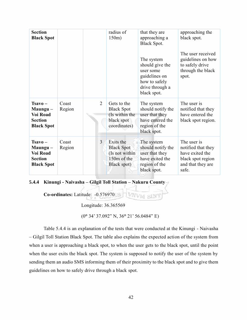
42
Section
Black Spot
radius of
150m)
that they are
approaching a
Black Spot.
The system
should give the
user some
guidelines on
how to safely
drive through a
black spot.
approaching the
black spot.
The user received
guidelines on how
to safely drive
through the black
spot.
Tsavo –
Maungu –
Voi Road
Section
Black Spot
Coast
Region
2 Gets to the
Black Spot
(Is within the
black spot
coordinates)
The system
should notify the
user that they
have entered the
region of the
black spot.
The user is
notified that they
have entered the
black spot region.
Tsavo –
Maungu –
Voi Road
Section
Black Spot
Coast
Region
3 Exits the
Black Spot
(Is not within
150m of the
Black spot)
The system
should notify the
user that they
have exited the
region of the
black spot.
The user is
notified that they
have exited the
black spot region
and that they are
safe.
5.4.4 Kinungi - Naivasha – Gilgil Toll Station – Nakuru County
Co-ordinates: Latitude: -0.576970
Longitude: 36.365569
(0° 34’ 37.092” N, 36° 21’ 56.0484” E)
Table 5.4.4 is an explanation of the tests that were conducted at the Kinungi - Naivasha
– Gilgil Toll Station Black Spot. The table also explains the expected action of the system from
when a user is approaching a black spot, to when the user gets to the black spot, until the point
when the user exits the black spot. The system is supposed to notify the user of the system by
sending them an audio SMS informing them of their proximity to the black spot and to give them
guidelines on how to safely drive through a black spot.
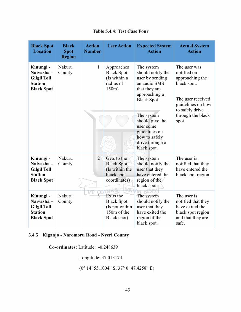
43
Table 5.4.4: Test Case Four
Black Spot
Location
Black
Spot
Region
Action
Number
User Action Expected System
Action
Actual System
Action
Kinungi -
Naivasha –
Gilgil Toll
Station
Black Spot
Nakuru
County
1 Approaches
Black Spot
(Is within a
radius of
150m)
The system
should notify the
user by sending
an audio SMS
that they are
approaching a
Black Spot.
The system
should give the
user some
guidelines on
how to safely
drive through a
black spot.
The user was
notified on
approaching the
black spot.
The user received
guidelines on how
to safely drive
through the black
spot.
Kinungi -
Naivasha –
Gilgil Toll
Station
Black Spot
Nakuru
County
2 Gets to the
Black Spot
(Is within the
black spot
coordinates)
The system
should notify the
user that they
have entered the
region of the
black spot.
The user is
notified that they
have entered the
black spot region.
Kinungi -
Naivasha –
Gilgil Toll
Station
Black Spot
Nakuru
County
3 Exits the
Black Spot
(Is not within
150m of the
Black spot)
The system
should notify the
user that they
have exited the
region of the
black spot.
The user is
notified that they
have exited the
black spot region
and that they are
safe.
5.4.5 Kiganjo - Naromoru Road - Nyeri County
Co-ordinates: Latitude: -0.248639
Longitude: 37.013174
(0° 14’ 55.1004” S, 37° 0’ 47.4258” E)
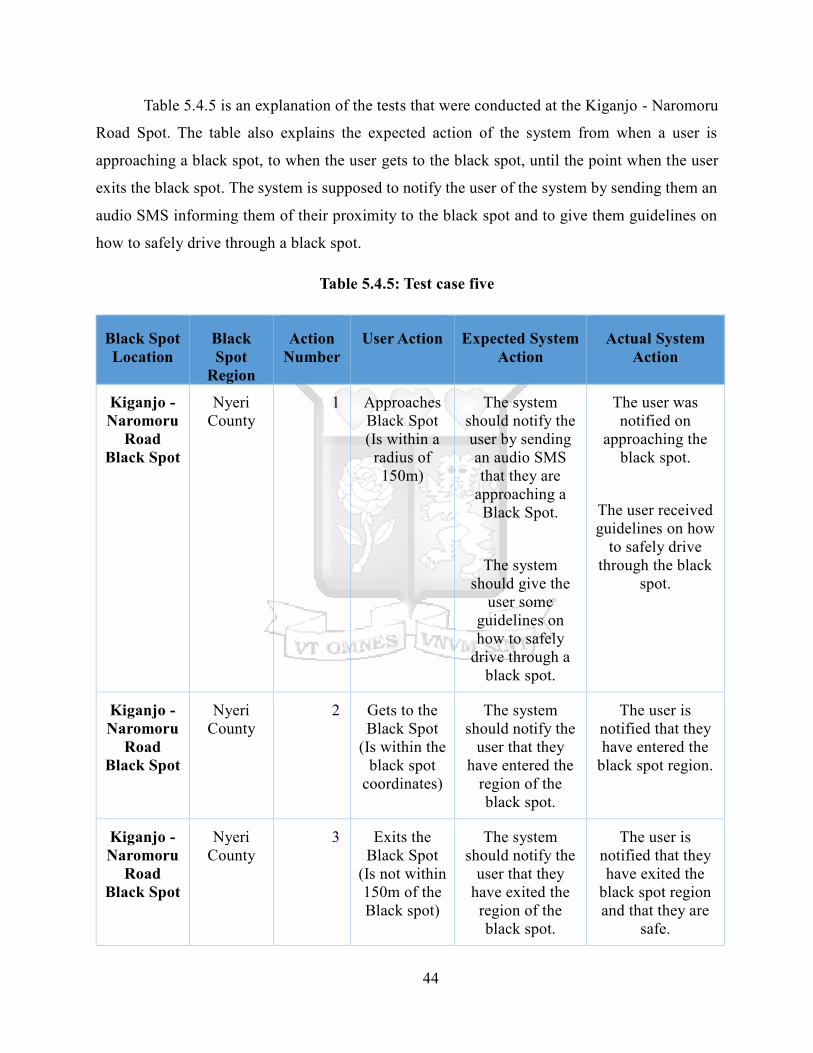
44
Table 5.4.5 is an explanation of the tests that were conducted at the Kiganjo - Naromoru
Road Spot. The table also explains the expected action of the system from when a user is
approaching a black spot, to when the user gets to the black spot, until the point when the user
exits the black spot. The system is supposed to notify the user of the system by sending them an
audio SMS informing them of their proximity to the black spot and to give them guidelines on
how to safely drive through a black spot.
Table 5.4.5: Test case five
Black Spot
Location
Black
Spot
Region
Action
Number
User Action Expected System
Action
Actual System
Action
Kiganjo -
Naromoru
Road
Black Spot
Nyeri
County
1 Approaches
Black Spot
(Is within a
radius of
150m)
The system
should notify the
user by sending
an audio SMS
that they are
approaching a
Black Spot.
The system
should give the
user some
guidelines on
how to safely
drive through a
black spot.
The user was
notified on
approaching the
black spot.
The user received
guidelines on how
to safely drive
through the black
spot.
Kiganjo -
Naromoru
Road
Black Spot
Nyeri
County
2 Gets to the
Black Spot
(Is within the
black spot
coordinates)
The system
should notify the
user that they
have entered the
region of the
black spot.
The user is
notified that they
have entered the
black spot region.
Kiganjo -
Naromoru
Road
Black Spot
Nyeri
County
3 Exits the
Black Spot
(Is not within
150m of the
Black spot)
The system
should notify the
user that they
have exited the
region of the
black spot.
The user is
notified that they
have exited the
black spot region
and that they are
safe.
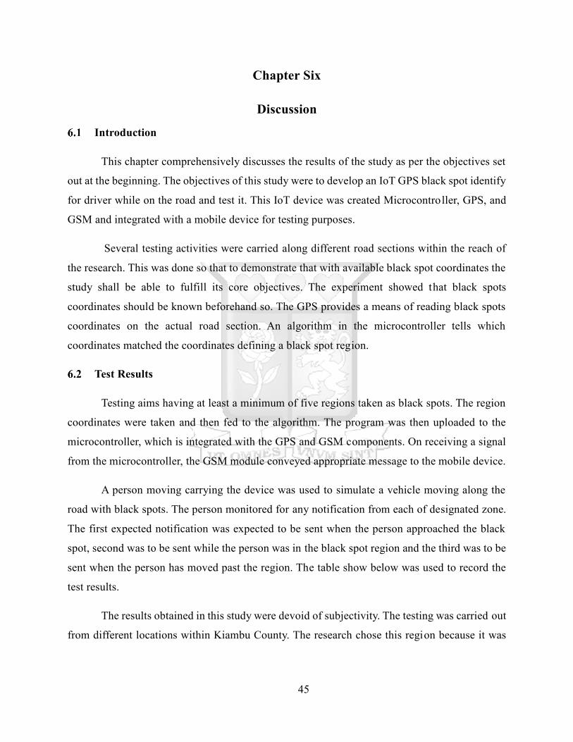
45
Chapter Six
Discussion
Introduction
This chapter comprehensively discusses the results of the study as per the objectives set
out at the beginning. The objectives of this study were to develop an IoT GPS black spot identify
for driver while on the road and test it. This IoT device was created Microcontroller, GPS, and
GSM and integrated with a mobile device for testing purposes.
Several testing activities were carried along different road sections within the reach of
the research. This was done so that to demonstrate that with available black spot coordinates the
study shall be able to fulfill its core objectives. The experiment showed that black spots
coordinates should be known beforehand so. The GPS provides a means of reading black spots
coordinates on the actual road section. An algorithm in the microcontroller tells which
coordinates matched the coordinates defining a black spot region.
Test Results
Testing aims having at least a minimum of five regions taken as black spots. The region
coordinates were taken and then fed to the algorithm. The program was then uploaded to the
microcontroller, which is integrated with the GPS and GSM components. On receiving a signal
from the microcontroller, the GSM module conveyed appropriate message to the mobile device.
A person moving carrying the device was used to simulate a vehicle moving along the
road with black spots. The person monitored for any notification from each of designated zone.
The first expected notification was expected to be sent when the person approached the black
spot, second was to be sent while the person was in the black spot region and the third was to be
sent when the person has moved past the region. The table show below was used to record the
test results.
The results obtained in this study were devoid of subjectivity. The testing was carried out
from different locations within Kiambu County. The research chose this region because it was
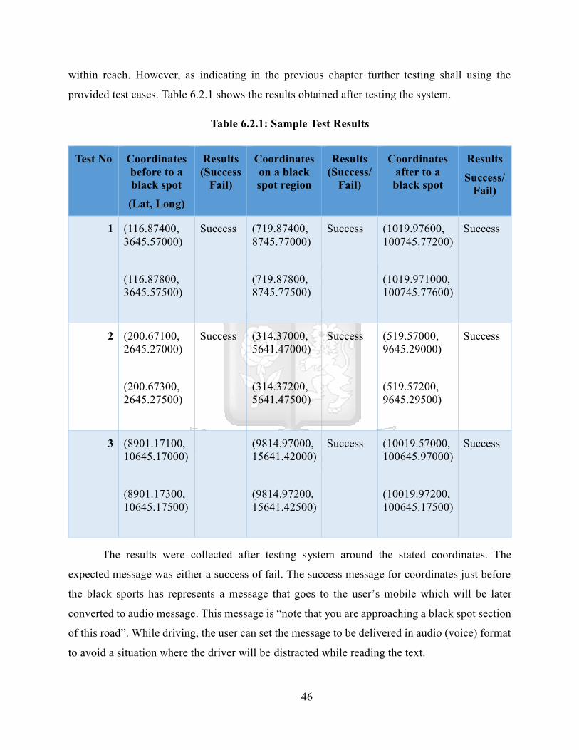
46
within reach. However, as indicating in the previous chapter further testing shall using the
provided test cases. Table 6.2.1 shows the results obtained after testing the system.
Table 6.2.1: Sample Test Results
Test No Coordinates
before to a
black spot
(Lat, Long)
Results
(Success
Fail)
Coordinates
on a black
spot region
Results
(Success/
Fail)
Coordinates
after to a
black spot
Results
Success/
Fail)
1 (116.87400,
3645.57000)
(116.87800,
3645.57500)
Success (719.87400,
8745.77000)
(719.87800,
8745.77500)
Success (1019.97600,
100745.77200)
(1019.971000,
100745.77600)
Success
2 (200.67100,
2645.27000)
(200.67300,
2645.27500)
Success (314.37000,
5641.47000)
(314.37200,
5641.47500)
Success (519.57000,
9645.29000)
(519.57200,
9645.29500)
Success
3 (8901.17100,
10645.17000)
(8901.17300,
10645.17500)
(9814.97000,
15641.42000)
(9814.97200,
15641.42500)
Success (10019.57000,
100645.97000)
(10019.97200,
100645.17500)
Success
The results were collected after testing system around the stated coordinates. The
expected message was either a success of fail. The success message for coordinates just before
the black sports has represents a message that goes to the user’s mobile which will be later
converted to audio message. This message is “note that you are approaching a black spot section
of this road”. While driving, the user can set the message to be delivered in audio (voice) format
to avoid a situation where the driver will be distracted while reading the text.
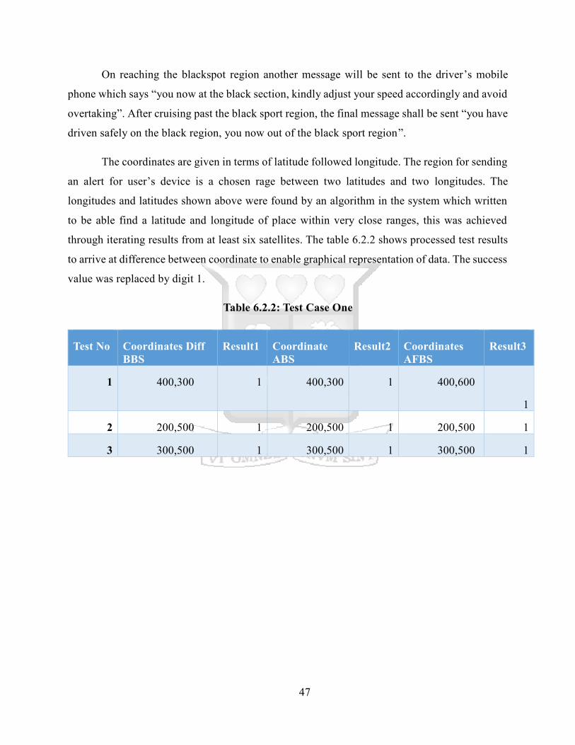
47
On reaching the blackspot region another message will be sent to the driver’s mobile
phone which says “you now at the black section, kindly adjust your speed accordingly and avoid
overtaking”. After cruising past the black sport region, the final message shall be sent “you have
driven safely on the black region, you now out of the black sport region”.
The coordinates are given in terms of latitude followed longitude. The region for sending
an alert for user’s device is a chosen rage between two latitudes and two longitudes. The
longitudes and latitudes shown above were found by an algorithm in the system which written
to be able find a latitude and longitude of place within very close ranges, this was achieved
through iterating results from at least six satellites. The table 6.2.2 shows processed test results
to arrive at difference between coordinate to enable graphical representation of data. The success
value was replaced by digit 1.
Table 6.2.2: Test Case One
Test No Coordinates Diff
BBS
Result1 Coordinate
ABS
Result2 Coordinates
AFBS
Result3
1 400,300 1 400,300 1 400,600
1
2 200,500 1 200,500 1 200,500 1
3 300,500 1 300,500 1 300,500 1
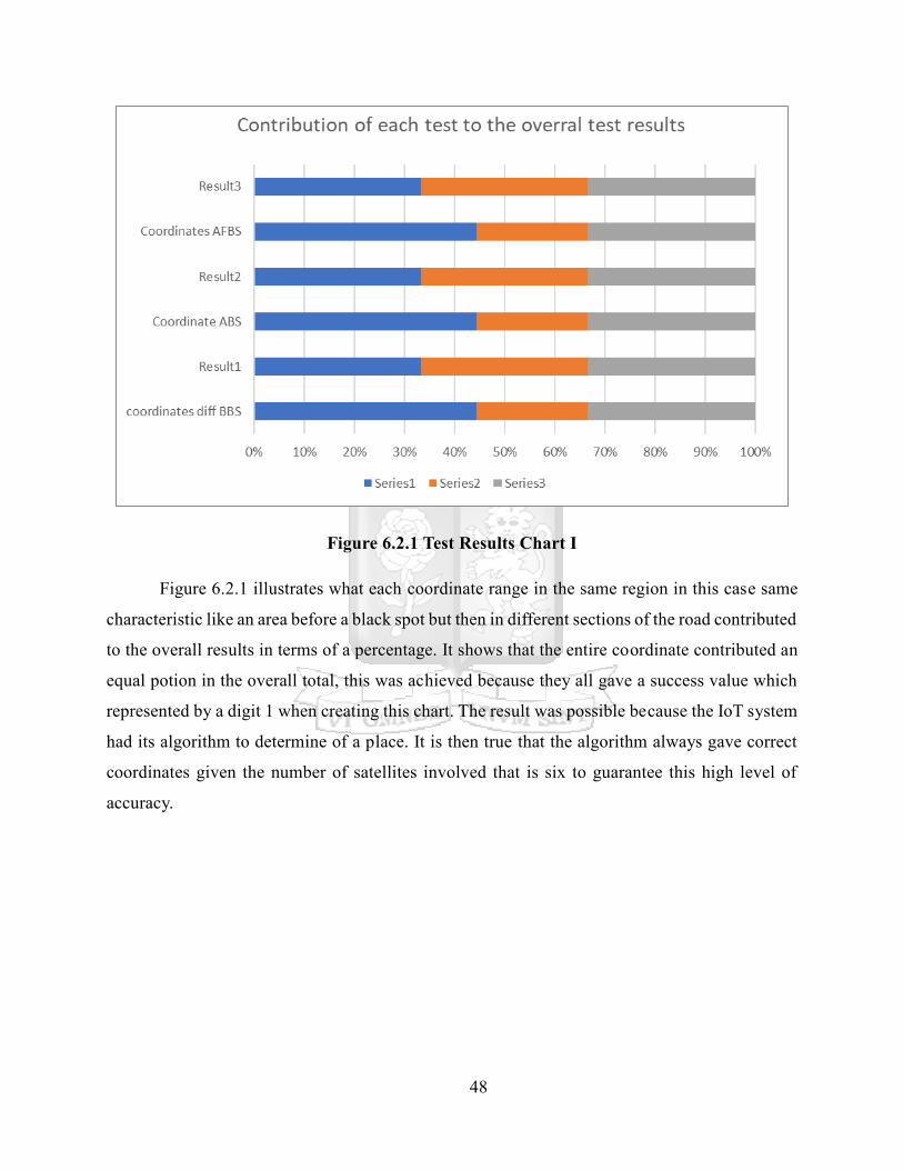
48
Figure 6.2.1 Test Results Chart I
Figure 6.2.1 illustrates what each coordinate range in the same region in this case same
characteristic like an area before a black spot but then in different sections of the road contributed
to the overall results in terms of a percentage. It shows that the entire coordinate contributed an
equal potion in the overall total, this was achieved because they all gave a success value which
represented by a digit 1 when creating this chart. The result was possible because the IoT system
had its algorithm to determine of a place. It is then true that the algorithm always gave correct
coordinates given the number of satellites involved that is six to guarantee this high level of
accuracy.
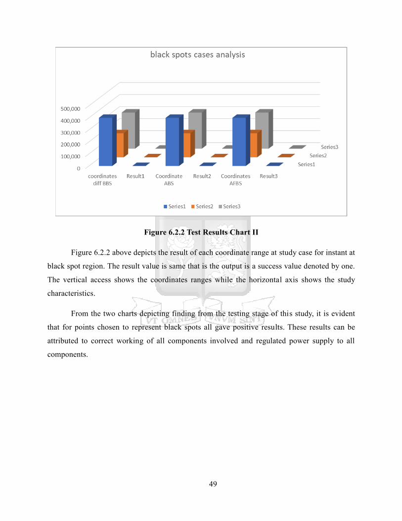
49
Figure 6.2.2 Test Results Chart II
Figure 6.2.2 above depicts the result of each coordinate range at study case for instant at
black spot region. The result value is same that is the output is a success value denoted by one.
The vertical access shows the coordinates ranges while the horizontal axis shows the study
characteristics.
From the two charts depicting finding from the testing stage of this study, it is evident
that for points chosen to represent black spots all gave positive results. These results can be
attributed to correct working of all components involved and regulated power supply to all
components.

50
Chapter Seven
Conclusion and Recommendations
Conclusion
This study was focused on developing an IoT black spot identification GPS for drivers.
The system uses GPS to find coordinates while a driving on the road. To ensure that project
successfully achieves its objectives several components were put together during its
development. Enough literature review was conducted on each of the component used in this
study to ascertain their suitability in the project. There was also need to factor in user expectation;
sampled out of drivers were interview regarding their view expectations and suggestions so that
the built system fits well in their scenario.
a) The first and second objectives were achieved through a comprehensive literature
review, which involved looking at different sources of knowledge available and
determining the available techniques for identifying dangerous road sections and
challenges this means pose to the drivers.
b) The third and fourth objectives were realized by building an IoT GPS based black
spot system and testing against selected coordinates to ascertain its performance
and accuracy.
The main objective of this study was developing a black spot identifying system which
could then result in reduction of number accidents which occur in this section of the road. The
black spot information was collected using GPS pin. The black spots data used in this study are
predefined. However, because of the distant location of the actual black spot zones, a few points
within reach of the research were selected to represent the really zone to assist testing the
functionality of the system.
The results obtained from system testing were analyzed to validate the usability and
credibility of the system. The results showed that the system can be used in really time
environment to assists drivers make right decision whenever they approach a dangerous road
section.
51
Recommendation
a) This study showed it is possible to identify dangerous road sections interims of
its GPS coordinates. It is also possible to relay this information to the drivers
using appropriate message modes. The proposed system is however, decoupled
from the entire vehicle systems.
b) Black spot identification system can be made much better by integrating the
proposed system to vehicle system. This will provide a better level of abstraction
than having it isolated.
c) The isolation proves to be a bit cumbersome and components can get disconnected
easily when the vehicle is moving especially in bumpy roads.
d) It will also be a good idea to incorporate a system that determines black spot
coordinates in really time as opposed to relying in predefined points. When data
from black spot is more dynamic the system will attract more users and its benefits
shall span a wide scope.
Future work
The proposed system leans to just providing drivers about the black spot information and
directives. This system can be extended to cover entire traffic events such notifying the drivers
about the road blocks on the roads, alerting drivers whenever there is an accident a head and
perhaps whether this accident can result to traffic jams so that he/she can change course.
The project can also be made around to be a data generating system for further analysis
by traffic experts. For instance, it can be providing data to traffic control agencies on the impact
it has on drivers’ behavior around the black spots. This information can assist the government
make decisions on possibilities of deploying the projects to various transport systems.
52
References
African Development Bank (2013). Road Safety in Africa: Assessment of Progresses and
Challenges in Road Safety Management System. Transport & ICT Department.
Ansari, S., Akhdar, F., Mandoorah, M., & Moutaery, K. (2000). Causes and effects of road traffic
accidents in Saudi Arabia. Public health, 114(1), 37-39.
Bae, Y. K., & Benítez‐Silva, H. (2011). Do vehicle recalls reduce the number of accidents? The
case of the US car market. Journal of Policy Analysis and Management, 30(4), 821-862.
Barbour, R. (2001). Checklists for improving rigor in qualitative research: A case of the tai l
wagging the dog? British Medical Journal, 322, 1115–1117.
Broughton, J., & Water, L. (2007). Trends in Fatal Car Accidents: Analyses of CCIS Data. TRL
Report PPR172. Transport Research Laboratory, Crowthorne.
Castrejon-Pita, J. R., Baxter, W. R. S., Morgan, J., Temple, S., Martin, G. D., & Hutchings, I. M.
(2013). Future, opportunities and challenges of inkjet technologies. Atomization and
Sprays, 23(6), 541-565.
Chamarro, A., & Fernández-Castro, J. (2009). The perception of causes of accidents in mountain
sports: a study based on the experiences of victims. Accident Analysis &
Prevention, 41(1), 197-201.
Chen, H. (2012). Black Spot Determination of Traffic Accident Locations and its Spatial
Association Characteristic Analysis Based on GIS. Journal of Geographic
Information System, 4, 608-617.
Creswell, J.W. (2012). Educational Research: Planning, Conducting, and Evaluating
Quantitative and Qualitative Research. Upper Saddle River, NJ: Prentice Hall.
Dana, P. H. (1996). GPS Orbital Planes. Retrieved from
http://www.colorado.edu/geography/gcraft/notes/gps/gif/oplanes.gif.
Department of Transport and Regional Services (2004). Annual Report 2003–04. Australian
Government.
53
Ekpenyong, E. & Pius, O. (2015). Analysis of Reported Cases of Road Traffic Accidents in
Umuahia Metropolis. Journal of Applied Quantitative Methods, 10, 27-35.
European Commission. (2007). Summary and publication of best Practices in Road safety in
the E. U. Member States. Retrieved from
https://ec.europa.eu/transport/road_safety/sites/roadsafety/.../projects/supreme.pdf
European Telecommunications Standards Institute (2011). Cellular History. Retrieved from
https://www.etsi.org/.
Flick, K. E. (2005). U.S. Patent No. 6,888,495. Washington, DC: U.S. Patent and Trademark
Office.
Fuller, R., & Santos, J. A. (2002). Human Factors for Highway Engineers. Bingley, United
Kingdom: Emerald Group Publishing.
Hamilton-Baillie, B., & Jones, P. (2005). Improving traffic behavior and safety through urban
design. Proceedings of the Institution of Civil Engineers-Civil Engineering, 158, (5), 39-
47.
Hay, D. C. (2003). Requirements Analysis: From Business Views to Architecture (1st ed.). Upper
Saddle River, NJ: Prentice Hall.
Hegyi, P., Borsos, A., & Koren. (2017). Searching possible accident black spot locations
with accident analysis and GIS software based on GPS coordinates. Pollack
Periodica. 12. 129-140. 10.1556/606.2017.12.3.12.
Huurdeman, A. A. (2003). The Worldwide History of Telecommunications. New Jersey, NJ: John
Wiley & Sons, Inc.
Jørgensen, K. Concepts of Accident Analysis. Encyclopedia of Occupational Health and Safety.
International Labor Organization, Geneva.
Khalilikha, M. & Heaslip, K. (2016). The effects of damage on sign visibility: Journal of
Traffic and Transportation Engineering (English Edition), 6(3), 571-581.
54
Kotonya, G., & Sommerville, I. (1998). Requirements Engineering: Processes and
Techniques. Chichester, UK: John Wiley and Sons.
Laplante, P. (2009). Requirements Engineering for Software and Systems (1st ed.). Redmond,
WA: CRC Press. ISBN 1-4200-6467-3.
Lewis, K., R. (2018). Road signs that are too small or too confusing. The Washington Post.
Retrieved from https://www.washingtonpost.com/realestate/2018/01/25/b2c7859e-0081-
11e8-8acf-ad2991367d9d_story.html?noredirect=on&utm_term=.5f4af6396851.
Lohr, K., N. (2004). Rating the strength of scientific evidence: Relevance for quality
improvement programs. International Journal for Quality in Health Care, 16(1), 9-18.
Malik, F., A. (2017). Road Accidents and Prevention. International Journal of Engineering
Development and Research,5, 40-46.
Manyara C.G. (2016) Combating Road Traffic Accidents in Kenya: A Challenge for an Emerging
Economy. Palgrave Macmillan, New York.
McConnell, S. (1996). Rapid Development: Taming Wild Software Schedules (1st ed.).
Redmond, WA: Microsoft Press. ISBN 1-55615-900-5.
Min, W., & Wynter, L. (2011). Real-time road traffic prediction with spatio-temporal
correlations. Transportation Research Part C: Emerging Technologies, 19(4), 606-616.
Ministry of Transport- Kenya. (2005). National Road Safety Action Plan -2005-2010.
Mosteller, F., & Boruch, R. (Eds.). (2002). Evidence matters: Randomized trials in education
research. Washington, DC: The Brookings Institute.
Nuseibeh, B., & Easterbrook, S. (2000). Requirements Engineering: A
Roadmap ICSE'00. Proceedings of The Conference on The Future of Software
Engineering, Limerick, Ireland — June 04 - 11, 2000, pp.35-46.
O’Brien, K. J. (2009). Cellphone Encryption Code Is Divulged. The New York Times. Retrieved
from https://www.nytimes.com/2009/12/29/technology/29hack.html.
55
Olemo, C. D. (2016). Exploring the major causes of road traffic accidents in Nairobi County.
University of Nairobi.
Rumerman, J. A. (2009). NASA Historical Data Book, Volume VII. NASA.
Russell, R., M., & Hasik, M., J. (2002). The Precision Revolution: GPS and the Future of Aerial
Warfare. Annapolis, MD: Naval Institute Press.
Salgues, B. (1997). Les Telecoms Mobiles, GCS, DCS. Paris, Hermes Science.
Sauter, M. (2014). From GSM to LTE-Advanced: An Introduction to Mobile Networks and Mobile
Broadband, Revised Second Edition. New Jersey, NJ: John Wiley & Sons.
Stellman, A., & Greene, J. (2005). Applied Software Project Management. California, CA:
O'Reilly.
Tan, R. T., Pettersson, N., & Petersson, L. (2007). Visibility enhancement for roads with foggy
or hazy scenes. In IEEE Intelligent Vehicles Symposium, 19-24. IEEE.
Teymourzadeh, R., Ahmed, S. A., Chan, K. W., & Hoong, M. V. (2013). Smart GSM based Home
Automation System. 2013 IEEE Conference on Systems, Process & Control (ICSPC) pp.
306-309. IEEE.
Thomas, M. O., & Rad, B. B. (2017). Reliability Evaluation Metrics for Internet of Things, Car
Tracking System: A Review. International Journal of Computer Science and Information
Technology 9(2), 1–10.
Vandana, S. (2003). Soldiers take digital assistants to war. GCN.com. Retrieved
from https://gcn.com/articles/2003/07/24/soldiers-take-digital-assistants-to-war.aspx.
Weigers, K., & Beatty, J. (2013). Software Requirements (3rd ed.). Redmond, WA: Microsoft
Press.
Westbrook, L. D., & Richharia, M. (2010). Satellite Systems for Personal Applications: Concepts
and Technology. New Jersey, NY: John Wiley & Sons.

56
World Health Organization. (2009). Global Status Report on Road Safety Time for Action.
Geneva, W.H.O.

57
Appendix A
Interview Guide
I am developing a GPS based Internet of things applications. This application shall be
able to notify the driver, whenever they come close to a blackspot, in the sense that it I will
provide instructions on what to do like reducing the cruising speed, avoid overtaking.
Fill your views, suggestions and comments in the following questions.
1) Do you think this strategy will reduce number of accidents?
Yes no (mark your option)
2) What type of notification would prefer to receive?
a) Text b) audio c) visual
3) What are the features you may expect from such a system?
................................................................................................. .......................................
……………………………………………………………………………………………
……………………………………………………………………………………………
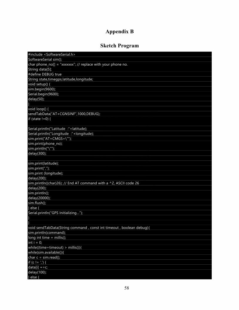
58
Appendix B
Sketch Program
#include <SoftwareSerial.h>
SoftwareSerial sim();
char phone_no[] = “xxxxxxx”; // replace with your phone no.
String data[5];
#define DEBUG true
String state,timegps,latitude,longitude;
void setup() {
sim.begin(9600);
Serial.begin(9600);
delay(50);
}
void loop() {
sendTabData(“AT+CGNSINF”,1000,DEBUG);
if (state !=0) {
Serial.println(“Latitude :”+latitude);
Serial.println(“Longitude :”+longitude);
sim.print(“AT+CMGS=\””);
sim.print(phone_no);
sim.println(“\””);
delay(300);
sim.print(latitude);
sim.print(“,”);
sim.print (longitude);
delay(200);
sim.println((char)26); // End AT command with a ^Z, ASCII code 26
delay(200);
sim.println();
delay(20000);
sim.flush();
} else {
Serial.println(“GPS Initializing…”);
}
}
void sendTabData(String command , const int timeout , boolean debug){
sim.println(command);
long int time = millis();
int i = 0;
while((time+timeout) > millis()){
while(sim.available()){
char c = sim.read();
if (c != ‘,’) {
data[i] +=c;
delay(100);
} else {
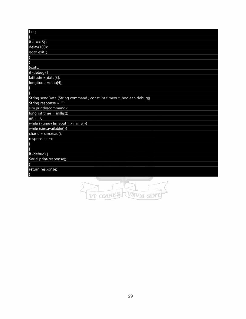
59
i++;
}
if (i == 5) {
delay(100);
goto exitL;
}
}
}exitL:
if (debug) {
latitude = data[3];
longitude =data[4];
}
}
String sendData (String command , const int timeout ,boolean debug){
String response = “”;
sim.println(command);
long int time = millis();
int i = 0;
while ( (time+timeout ) > millis()){
while (sim.available()){
char c = sim.read();
response +=c;
}
}
if (debug) {
Serial.print(response);
}
return response;
}

60
Appendix C
Originality Report