A formal analysis technique for secure software architectures
218
Arenberg Doctoral School Faculty of Engineering A FORMAL ANALYSIS TECHNIQUE FOR SECURE SOFTWARE ARCHITECTURES Thomas HEYMAN Dissertation presented in partial fulfillment of the requirements for the degree of Doctor in Engineering March 2013
-
Upload
khangminh22 -
Category
Documents
-
view
0 -
download
0
Transcript of A formal analysis technique for secure software architectures

Arenberg Doctoral SchoolFaculty of Engineering
A FORMAL ANALYSIS TECHNIQUE FORSECURE SOFTWARE ARCHITECTURES
Thomas HEYMAN
Dissertation presented in partial
fulfillment of the requirements for
the degree of Doctor in Engineering
March 2013


A formal analysis technique for securesoftware architectures
Thomas HEYMAN
Jury:Prof. dr. A. Bultheel, chairProf. dr. ir. W. Joosen, supervisorDr. ir. R. Scandariato, co-supervisorProf. dr. T. HolvoetProf. dr. B. JacobsProf. dr. ir. F. PiessensProf. dr. ir. B. PreneelProf. dr. M. Clavel(Universidad Complutense de Madrid)(IMDEA Software Institute)
Prof. dr. V. Jonckers(SOFT, Vrije Universiteit Brussel)
Dissertation presented in partialfulfillment of the requirements forthe degree of Doctor inEngineering
March 2013

© KU Leuven – Faculty of EngineeringCelestijnenlaan 200A box 2402, B-3001 Heverlee (Belgium)
Alle rechten voorbehouden. Niets uit deze uitgave mag worden vermenigvuldigden/of openbaar gemaakt worden door middel van druk, fotocopie, microfilm,elektronisch of op welke andere wijze ook zonder voorafgaande schriftelijketoestemming van de uitgever.
All rights reserved. No part of the publication may be reproduced in any form byprint, photoprint, microfilm or any other means without written permission from thepublisher.
D/2013/7515/25ISBN 978-94-6018-638-7

Acknowledgements
It took me a while to create the document you are currently reading. During that time,I have learned many things, run into many problems and frustrations, seen manyplaces, gained many friends, and met the person I now share my life with. As thesaying goes, it is indeed the journey that matters. We learn by going where we haveto go.
I want to thank my supervisor Wouter Joosen for the opportunity to pursue a PhDand the vision to put me on course, my co-supervisor Riccardo Scandariato for thecontinual guidance and advice, the members of the jury for their insightful feedback(which is sure to bring forth interesting future work), and my colleagues and officemates from iMinds-DistriNet that make it such a great place to work—especiallyKoen Yskout and Lieven Desmet for the always thought-provoking discussions, DaveClarke for patiently helping me out with all that model theory, and Marko van Doorenfor the tool support. Thanks to the members of the department of Computer Scienceand the research community at large I had the honor and pleasure of meeting andworking with over the years. It has been a tremendous experience.
I could not have done this without the support of my family, especially my motherLieve, father Walter and brother Jefri. I am also greatly indebted to my friends bothhere and abroad for keeping me afloat, and most of all to Raquel, whom I love verymuch. Coincidentally, she is also an awesome navigator. Thank you all.
This research would not have been possible without the financial support of iMindsand the IWT. It is partially funded by the Research Fund KU Leuven, and by the EU FP7project NESSoS. It has been realised with the financial support from the Preventionof and Fight against Crime Programme of the European Union.
i


Abstract
Security is no sugar coating that can be added to a software system as an afterthought;a software system should be designed securely from the start. Over the years, manyapproaches have been conceived that analyse the security of a software systemthroughout the various phases of the software development process. One phasein particular, software architecture design, has proven to be crucial in this process.
Analysis methods for software architecture security can be subdivided into twocategories: engineering methods and formal methods. While engineering methodsexcel in achieving reasonable security with reasonable effort, formal methods canprovide stronger security guarantees in return for an often much larger investment.However, formal methods do not always take the intricacies of software architecturedesign into account. This includes providing support for the decomposition of largemodels, information hiding through abstraction, reuse of verification results, creatingpartial models with incomplete information early in the design phase, catering tothe various stakeholders involved in software development, and integration of themodelling process itself in a larger enterprise risk management process. This lastfeature is critical—if the residual risk inherent in a security analysis is not madeexplicit, then the results of a formal analysis can be correct in theory but worthlessin practise.
The central thesis of this dissertation is that it is possible to bring both categoriesof secure software architecture analysis methods closer together. We propose anovel formal modelling and verification technique for software architectures thatis based on model finding. By systematically eliciting assumptions, we enableintegration of the verification results in a risk management process, and facilitate theinvolvement of various stakeholders such as the security expert, application deployerand requirements engineer. Furthermore, we prove that the verification results arecomposable, which in turn supports information hiding through abstraction, reusing(partial) verification results, and makes the verification of large models tractable.
The modelling technique is verified by creating a reusable library of a securitypattern language for accountability, in which a number of relevant undocumentedassumptions are uncovered that were left implicit in the original documentation. Theusability of this library is demonstrated through a small but rigorous observational
iii

iv ABSTRACT
case study, which shows that non experts can use this library to create securearchitectural compositions. We verify that the approach supports mainstreamarchitectural modelling practises, and that the verification supports mainstreamsecurity properties. We also illustrate how extra language concepts can be leveragedto improve upon the proposed modelling technique. We conclude that it is possibleto bring both the secure software architecture engineering community and formalcommunity closer together, a longer term process in which this work is a first step.

Beknopte samenvatting
Beveiliging is geen decoratie die achteraf aan een softwaresysteem kan wordentoegevoegd, een softwaresysteem moet veilig ontworpen worden vanaf het begin.Door de jaren heen zijn er reeds vele aanpakken bedacht die de veiligheid van eensoftwaresysteem analyseren tijdens de verscheidene fases van het ontwikkelingspro-ces. Een van die fases in het bijzonder, het ontwerpen van een software-architectuur,blijkt cruciaal in dat proces.
Methodes voor de beveiligingsanalyse van software-architecturen kunnen grotendeelsin twee categorieën ondergebracht worden: ingenieursmethodes en formele methodes.Terwijl de ingenieursmethodes uitblinken in het verschaffen van een redelijk niveauvan beveiliging in ruil voor een redelijke inspanning, kunnen formele methodeseen veel sterker niveau van veiligheid garanderen voor een meestal veel grotereinspanning. Maar formele methodes nemen niet altijd de subtiliteiten van eensoftware-architecturaal ontwerp in beschouwing. Dat houdt onder meer in dat ze nietaltijd ondersteuning bieden voor het opsplitsen van grote modellen, het verbergenvan informatie door middel van abstractie, het hergebruiken van verificatieresultaten,en het creëren van partiële modellen vroeg in de ontwerpfase. Bovendien nemen zede verscheidene belanghebbenden die betrokken zijn bij het software-ontwerpprocesniet altijd in beschouwing, en is het ontwerpproces zelf niet altijd te integreren in eenalgemeen risicobeheersproces. Dat laatste element is cruciaal. Als het overblijvenderisico inherent aan een beveiligingsanalyse niet expliciet gemaakt wordt, kunnen deresultaten van een formele analyse correct zijn in theorie, maar waardeloos in depraktijk.
De centrale stelling van deze dissertatie is dat het mogelijk is om beide kampenvan analysemethodes voor de beveiliging van software-architecturen dichter bijelkaar te brengen. We stellen een nieuwe formele modelleer- en verificatietechniekvoor software-architecturen voor die gebaseerd is op het vinden van modellen.Door systematisch assumpties bloot te leggen, kunnen we de verificatieresultatenintegreren in een risicobeheersproces. Zo vereenvoudigen we de betrekkingvan de belanghebbenden als de beveiligingsexpert, de software-installateur, envereistenexpert. Voorts bewijzen we dat de verificatieresultaten samenstelbaar zijn.Dat ondersteunt het verbergen van informatie door abstractie en het hergebruikenvan (partiële) verificatieresultaten. Ook maakt het de verificatie van grote modellen
v

vi BEKNOPTE SAMENVATTING
mogelijk.
We evalueren de techniek door een herbruikbare bibliotheek van een taal vanbeveiligingspatronen voor het domein van toerekenbaarheid te creëren. Daarinontdekken we een aantal relevante assumpties die impliciet bleven in de origineledocumentatie. De bruikbaarheid van deze bibliotheek tonen we aan door een kleinemaar rigoreuze observationele gevalsstudie, die toont dat non-experts deze bibliotheekkunnen gebruiken om veilige architecturale composities te creëren. We verifiërendat de modelleeraanpak gangbare architecturale modelleerpraktijken ondersteunt,en de verificatie gangbare beveiligingseigenschappen. We illustreren ook hoe extrataalconcepten kunnen worden aangewend om de voorgestelde modelleertechniek teverbeteren. We concluderen dat het mogelijk is om de ingenieursgemeenschap en deformele gemeenschap voor software-architecturale beveiliging dichter bij elkaar tebrengen, een langetermijnproces waarin dit werk een eerste stap is.

Contents
Abstract iii
Beknopte samenvatting v
Contents vii
1 Introduction 1
1.1 Setting the scene . . . . . . . . . . . . . . . . . . . . . . . . . . . . . . . . 2
1.2 Problem statement . . . . . . . . . . . . . . . . . . . . . . . . . . . . . . . 3
1.3 Contributions of this text . . . . . . . . . . . . . . . . . . . . . . . . . . . 5
2 Background 9
2.1 Engineering secure software architectures . . . . . . . . . . . . . . . . . 10
2.1.1 A brief overview of secure software engineering . . . . . . . . 10
2.1.2 The Microsoft Secure Development Lifecycle and STRIDE . . . 12
2.1.3 ATAM . . . . . . . . . . . . . . . . . . . . . . . . . . . . . . . . . . 14
2.1.4 Risk assessment and CORAS . . . . . . . . . . . . . . . . . . . . 17
2.2 Formal analysis of secure software architectures . . . . . . . . . . . . . 19
2.2.1 An overview of formal secure modelling methods . . . . . . . . 19
2.2.2 UMLSec . . . . . . . . . . . . . . . . . . . . . . . . . . . . . . . . . 21
2.2.3 The Software Specification and Analysis Method . . . . . . . . 24
2.2.4 A brief introduction to Alloy . . . . . . . . . . . . . . . . . . . . 25
vii

viii CONTENTS
2.2.5 Automated verification with the Alloy Analyzer . . . . . . . . . 28
2.3 Conclusion . . . . . . . . . . . . . . . . . . . . . . . . . . . . . . . . . . . . 29
3 Security centric modelling of software architectures 31
3.1 Introduction . . . . . . . . . . . . . . . . . . . . . . . . . . . . . . . . . . . 31
3.2 Ingredients for formally modelling architectures . . . . . . . . . . . . . 34
3.2.1 Important architectural views . . . . . . . . . . . . . . . . . . . . 34
3.2.2 Integrating architectural views in a meta model . . . . . . . . . 37
3.2.3 Expressing and verifying security requirements . . . . . . . . . 42
3.2.4 Meta model revisited . . . . . . . . . . . . . . . . . . . . . . . . . 43
3.3 Uncovering hidden assumptions through model relaxation . . . . . . . 44
3.3.1 Relaxation rules . . . . . . . . . . . . . . . . . . . . . . . . . . . . 45
3.3.2 Supporting relaxation via the meta model . . . . . . . . . . . . 46
3.4 Constructive model analysis . . . . . . . . . . . . . . . . . . . . . . . . . 47
3.4.1 Creating an initial model context . . . . . . . . . . . . . . . . . . 47
3.4.2 Refining the model context . . . . . . . . . . . . . . . . . . . . . 50
3.4.3 Stakeholder involvement . . . . . . . . . . . . . . . . . . . . . . . 52
3.5 Discussion . . . . . . . . . . . . . . . . . . . . . . . . . . . . . . . . . . . . 54
3.6 Conclusion . . . . . . . . . . . . . . . . . . . . . . . . . . . . . . . . . . . . 57
4 Decomposing large architectural models 59
4.1 Introduction . . . . . . . . . . . . . . . . . . . . . . . . . . . . . . . . . . . 59
4.2 Background . . . . . . . . . . . . . . . . . . . . . . . . . . . . . . . . . . . 60
4.2.1 Background on model theory . . . . . . . . . . . . . . . . . . . . 60
4.2.2 Modelling a software architecture . . . . . . . . . . . . . . . . . 62
4.2.3 The verification process . . . . . . . . . . . . . . . . . . . . . . . 63
4.3 Limits of model finding . . . . . . . . . . . . . . . . . . . . . . . . . . . . 64
4.4 Splitting up large models . . . . . . . . . . . . . . . . . . . . . . . . . . . 68

CONTENTS ix
4.5 Scalable analysis via model decomposition . . . . . . . . . . . . . . . . . 71
4.5.1 Model refinement . . . . . . . . . . . . . . . . . . . . . . . . . . . 71
4.5.2 Interpreting models on different levels of abstraction . . . . . . 74
4.5.3 Abstraction based verification . . . . . . . . . . . . . . . . . . . . 81
4.6 Model decomposition in practise . . . . . . . . . . . . . . . . . . . . . . . 87
4.6.1 Abstracting the Logger . . . . . . . . . . . . . . . . . . . . . . . . 89
4.6.2 Abstracting the AuditInterceptor . . . . . . . . . . . . . . . . . . 92
4.6.3 Abstracting the Service . . . . . . . . . . . . . . . . . . . . . . . . 93
4.6.4 Putting it all together . . . . . . . . . . . . . . . . . . . . . . . . . 95
4.7 Discussion . . . . . . . . . . . . . . . . . . . . . . . . . . . . . . . . . . . . 98
4.7.1 Trading off formal guarantees and practical applicability . . . 98
4.7.2 Creating good abstractions . . . . . . . . . . . . . . . . . . . . . 99
4.8 Conclusion . . . . . . . . . . . . . . . . . . . . . . . . . . . . . . . . . . . . 100
5 Modelling security patterns 101
5.1 Introduction . . . . . . . . . . . . . . . . . . . . . . . . . . . . . . . . . . . 101
5.2 Modelling architectural patterns . . . . . . . . . . . . . . . . . . . . . . . 102
5.2.1 Translating essential pattern concepts to Alloy . . . . . . . . . 103
5.2.2 Creating connected abstract models . . . . . . . . . . . . . . . . 104
5.2.3 Security patterns and trust assumptions . . . . . . . . . . . . . . 105
5.3 A formal pattern language . . . . . . . . . . . . . . . . . . . . . . . . . . . 106
5.3.1 Authentication Enforcer . . . . . . . . . . . . . . . . . . . . . . . 106
5.3.2 Secure Pipe . . . . . . . . . . . . . . . . . . . . . . . . . . . . . . . 115
5.3.3 Secure Logger . . . . . . . . . . . . . . . . . . . . . . . . . . . . . 118
5.3.4 Audit Interceptor . . . . . . . . . . . . . . . . . . . . . . . . . . . 119
5.3.5 Authorization Enforcer . . . . . . . . . . . . . . . . . . . . . . . . 119
5.4 Discussion . . . . . . . . . . . . . . . . . . . . . . . . . . . . . . . . . . . . 120

x CONTENTS
5.5 Conclusion . . . . . . . . . . . . . . . . . . . . . . . . . . . . . . . . . . . . 123
6 Evaluation 125
6.1 Introduction . . . . . . . . . . . . . . . . . . . . . . . . . . . . . . . . . . . 125
6.2 Evaluating the support for mainstream modelling practises . . . . . . . 126
6.2.1 Explicit and implicit communication . . . . . . . . . . . . . . . . 126
6.2.2 Architectural styles . . . . . . . . . . . . . . . . . . . . . . . . . . 128
6.3 Evaluating the support for mainstream security properties . . . . . . . 133
6.3.1 Confidentiality . . . . . . . . . . . . . . . . . . . . . . . . . . . . . 133
6.3.2 Integrity . . . . . . . . . . . . . . . . . . . . . . . . . . . . . . . . . 135
6.3.3 Availability . . . . . . . . . . . . . . . . . . . . . . . . . . . . . . . 136
6.3.4 Authenticity . . . . . . . . . . . . . . . . . . . . . . . . . . . . . . 137
6.3.5 Accountability and privacy . . . . . . . . . . . . . . . . . . . . . 138
6.4 Evaluating the usability of the pattern library . . . . . . . . . . . . . . . 138
6.4.1 Participants . . . . . . . . . . . . . . . . . . . . . . . . . . . . . . . 138
6.4.2 Experimental object . . . . . . . . . . . . . . . . . . . . . . . . . . 139
6.4.3 Tasks . . . . . . . . . . . . . . . . . . . . . . . . . . . . . . . . . . . 139
6.4.4 Setup . . . . . . . . . . . . . . . . . . . . . . . . . . . . . . . . . . . 140
6.4.5 Measurements . . . . . . . . . . . . . . . . . . . . . . . . . . . . . 141
6.4.6 Observed results . . . . . . . . . . . . . . . . . . . . . . . . . . . . 141
6.4.7 Threats to validity . . . . . . . . . . . . . . . . . . . . . . . . . . . 144
6.5 Evaluating skills required for modelling . . . . . . . . . . . . . . . . . . 144
6.5.1 Creating abstract compositions . . . . . . . . . . . . . . . . . . . 144
6.5.2 Creating refined models . . . . . . . . . . . . . . . . . . . . . . . 146
6.6 Identifying modelling idiosyncrasies for improvement . . . . . . . . . . 147
6.6.1 Modelling idiosyncrasies . . . . . . . . . . . . . . . . . . . . . . . 148
6.6.2 Facilitating modelling with new language features . . . . . . . 150

CONTENTS xi
6.7 Conclusion . . . . . . . . . . . . . . . . . . . . . . . . . . . . . . . . . . . . 154
7 Conclusion 155
7.1 Lessons learned . . . . . . . . . . . . . . . . . . . . . . . . . . . . . . . . . 156
7.2 Future work . . . . . . . . . . . . . . . . . . . . . . . . . . . . . . . . . . . 158
7.2.1 Trust assumptions and security monitoring . . . . . . . . . . . 158
7.2.2 Supporting explicit attacker models . . . . . . . . . . . . . . . . 159
7.2.3 Improved tool support . . . . . . . . . . . . . . . . . . . . . . . . 160
A An architectural meta model in Alloy 163
B The Secure Logger 173
B.1 The refined Secure Logger model . . . . . . . . . . . . . . . . . . . . . . . 173
B.2 The first abstraction—AbstractLogger . . . . . . . . . . . . . . . . . . . . 179
B.3 The second abstraction—StatelessLogger . . . . . . . . . . . . . . . . . . 181
Bibliography 185
List of publications 197


List of Symbols
sig SecureLogger Font used to denote code.
Secure Logger Font used to denote security pattern names.
L A language.
M An architectural model description.
JMKL The interpretation of the model descriptionM in language L.
A,B, . . . Model instances.
C Glue model instance.
C ∼ C′ Two equivalent glue models.
[C] The class of all equivalent glue models to C.
π Canonical projection map that maps every glue model C to itsequivalence class [C].
X Attack instance (i.e., a counterexample).
A↓L Restriction of model instance A to language L.
−↓L Function thatmaps sets ofmodel instances to theirL-restriction.
g A behaviour preserving interpretation.
ga The abstract interpretation of g.
gr The refinement interpretation of g.
xiii


CHAPTER 1Introduction
Contemporary software systems do not work in isolation. Where in the early days ofsoftware engineering a system was developed for a specific situation and deployed ina fixed context, current systems almost always collaborate to achieve their tasks anddepend heavily on networking. Moreover, many long lived and legacy systems endup migrating to different deployment environments altogether, where they interactin ways that the original software developers might not have foreseen.
At the same time, increasing modularisation and reuse of libraries, softwarecomponents, middleware, and services, entail that more and more responsibilitiesof the application are moved beyond the direct control of the software systemdeveloper. In other words, the border between the core of a software system and itsenvironment is becoming vague at best. Essentially, the software system assumes thatthe environment correctly realizes these externalized responsibilities. And the moreresponsibilities are externalized to third-party libraries, components, middleware,or services, the more the correct operation of that software system depends on thecorrect operation of, and composition with, its environment.
Assumptions made by a software system on its environment are critical for security,as security is a property that emerges from the interaction of a system with theenvironment in which it is deployed. In order to assess whether a software system issecure, these assumptions should be made explicit. Additionally, in order to build asolid security assurance argument, these assumptions should be handled rigorously—even formally. Section 1.1 motivates why formal software architecture designmethodsfor security are a good idea. However, formal methods are misaligned with the currentpractice of software engineering. Most formal methods are not developed with thesoftware architect in mind, they are not risk aware, and lack comprehensive support toelicit and reason about these assumptions during architectural design, as outlined inSection 1.2. The contribution of this dissertation, as outlined in Section 1.3, is a usableformal modelling and analysis technique to verify whether a software architecture
1

2 CHAPTER 1 ◾ INTRODUCTION
is secure, with explicit support for taking assumptions of the software system on itsenvironment into account.
1.1 Setting the scene
A software system is created to perform one or more tasks, specified in the formof functional requirements. These functional requirements should be realized ina specific qualitative way—for instance, taking certain performance, adaptability,usability and security requirements into account. These additional requirements arecalled non-functional requirements, qualities, or simply ‘ilities’, and their correctrealization is what frequently distinguishes successful from unsuccessful systems[BCK03]. Requirements engineering is the branch of software engineering thatoccupies itself with the systematic elicitation and refinement of both functional andnon-functional requirements. Some specific requirements engineering approachesare UML use cases [JCJÖ92], KAOS [vL00], and problem frames [Jac01]. Independentof the actual approach used, the end result is a list of implementable requirementsthat the system-to-be should uphold. Based on these requirements, the system canthen be designed, implemented, tested, and eventually deployed.
A key step in ensuring that a software system realizes its qualities, is designing asoftware architecture [BCK03]. According to ISO/IEC/IEEE standard 42010 [ISO11],which defines a conceptual model of software architecture descriptions, an architec-ture consists of the fundamental concepts or properties of a system in its environment,which are embodied in its elements, relationships, and in the principles of its designand evolution. It realizes the system requirements by assigning responsibilities toisolated units of deployment, called components [SGM02]. These components theninteract with each other’s interfaces and communicate over connectors to realize theintended system functionality.
Early studies have shown that it is five to one hundred times cheaper to fixfundamental flaws in the system early on [BB05], making analysis during the design ofa software system more cost-effective than finding and fixing bugs after the softwareis deployed. Especially for security, having strong guarantees that the system-to-beupholds its security requirements is essential, as even one security flaw in the designof the system suffices to compromise the entire system—a problem sometimes referredto as the brittleness of software security [Bel06]. Therefore, analyzing the securityproperties of a system on the architectural level is paramount.
Methods to analyze the security of a software architecture can be roughly groupedin two categories: engineering methods and formal methods. Engineering methodssuch as Microsoft’s Secure Development Lifecycle [HL06] are practical methods thatembrace current best practices to secure a software system. Their main characteristics

1.2 PROBLEM STATEMENT 3
are that they are scalable, fit well within current software development processes,and provide decent results with a nominal investment of effort. For instance, in[Mic], Microsoft claims that applying the SDL resulted in a reduction of disclosedvulnerabilities of 45% in the Windows operating system one year after release, and areduction of 91% in SQL Server three years after release. However, the flexibility andrelatively lower effort of these engineering methods come at a cost. In general, theobtained security assessment results are informal—they are often nothing more thana checklist of issues relevant to security, but neither allow rigorous reasoning aboutthe security of the system, nor provide any well-defined guarantees of completenessor even correctness of the verification results.
Formal approaches such as SAM [HYS+04] allow the software engineer to createmodels in a mathematically grounded language. The advantage of creating suchrigorous and well defined models is that they remove ambiguity and enable (partiallyor fully automated) verification of their correctness. It is well established that applyingformal modelling in software engineering pays off, especially when it is used fromearly on in the software development process and followed through to the finalstages [Bjo87, CW96, WLBF09, EKN+12, AJK+12]. The trade-off for creating suchrigorous models is that the formal modelling process is labour intensive, whichexplains why formal modelling is usually limited to critical parts of a software systemor algorithms, if it is applied at all. Formal methods are also not always properlyaligned with current software development processes. This misalignment rangesfrom a discrepancy in modelling abstractions (e.g., labelled transition systems andPetri nets versus components and connectors), to a lack of flexibility in the modellingprocess itself (e.g., lack of support for changing deployment environments, changingrequirements, or analyzing partial models early in the software design phase).
To summarize, software architecture design is an important phase in the softwaredevelopment process for ensuring that a software system upholds its securityrequirements. Formal methods for security provide strong arguments for theiradoption in the software architecture design phase, such as enabling rigorousreasoning, providing correctness and completeness arguments, and supportingautomated verification. However, formal methods often lack the practical applicabilityinherent in engineering methods.
1.2 Problem statement
The process of securing a software system permeates the entire life cycle of thatsystem—from inception to after it has been deployed. Therefore, securing a softwaresystem happens on various levels of abstraction, ranging from the organizational andmanagement level, over the software design level, down to the system and hardware

4 CHAPTER 1 ◾ INTRODUCTION
level. Throughout this process, and especially during the architectural design stage,risk analysis is a necessity. According to McGraw [McG04], disregarding risk at thislevel will lead to costly problems down the road. Additionally, external review (i.e.,outside the design team) of risk is often necessary. Actually, many stakeholders apartfrom the software architect are involved in the software security process, ranging fromthe requirements engineer, the security engineer that identifies and mitigates securityweaknesses, the risk manager that decides whether a certain risk is acceptable in abusiness context, the actual software engineers that implement the system, securitytesters (also called ‘pentesters’) to verify that the security mitigations are sufficient,and the system deployer and maintainer that are responsible for instantiating thesystem and its day to day care.
A usable formal method for software architecture security should heed the observationsthat securing a software system spans many levels of abstraction, is grounded inrisk, and involves many stakeholders. This does not mean that the ideal formalmethod spans the entire breadth of the software development spectrum and catersto all stakeholders equally (actually, the converse is true: a good formal method isscoped and does one thing well [CW96, vL00]). However, it should strive to be easilyintegrated in larger software development and security processes. Therefore, it shouldexplicitly support refinement of security critical parts of the architecture and hidingof irrelevant details through abstraction, risk assessment, and anticipate interactionwith various stakeholders.
So what connects architectural refinement to risk and serves as a bridge betweenstakeholders? According to Haley et al. [HLMN04], key to deciding which parts ofthe environment of the system need further analysis and which do not, are trustassumptions. Trust assumptions are the decision about how much to trust1 thesupplied indicative (i.e., objectively true) properties of the environment of a softwaresystem. These assumptions are common in all security analysis methods—after all,the result of the security analysis of a software system is necessarily relative tothe environment of that system. For instance, authentication based on passwordsassumes that the passwords of user accounts are kept private. This is a non-trivialassumption—what about when the web browser on a public computer stores yourpassword, or when you are actually giving your password to a malicious site (as in so-called phishing attacks)? None of these situations actually involves the application towhich you want to authenticate. In other words, correctly managing a password is aninherent part of the environment of the system, and can never be achieved completelyby that system itself. This moves part of the responsibility of authentication to theenvironment (e.g., the web browser, operating system, and network) of that system.
1Note that trust, as used here, is not to be confused with trustworthiness, which is often defined asthe holistic property that encompasses security, safety and reliability [Ber05]. We also do not meantrustworthiness between humans and organizations (i.e., honesty, trustfulness, and competence), as is thecase in the work by Giorgini, Massacci et al. [GMMZ06].

1.3 CONTRIBUTIONS OF THIS TEXT 5
Documenting trust assumptions is crucial during risk assessment. For instance, thethreat that information is disclosed over a connection could be discarded because thatcommunication channel is behind a firewall. If the underlying assumption (e.g., “thecommunication channel is behind a firewall”) is not explicitly documented, then anychange to the environment of that system risks voiding the results of the securityanalysis, thereby rendering the system insecure. Therefore, an explicit enumerationof the set of assumptions in which the analysis is grounded is necessary to back upthe analysis result and to build a supporting assurance argument. A security analysisshould make these trust assumptions explicit by either specifying what guaranteesthe environment offers, or what properties the environment needs to uphold.
However, support for explicit reasoning about assumptions on the level of softwarearchitectures is lacking, as we will see in Chapter 2. Engineering methods recognizethe importance of making the underlying trust assumptions explicit. This mostlyhappens informally, which inhibits rigorous reasoning and automated completenessand correctness checks. In formal methods, on the other hand, assumptions areembedded in the model used for the analysis and are often implicit. For instance,availability weaknesses are not discovered if the model can not represent the case offailing components. Clearly, if the assumptions on which the analysis is based arenot realistic, the result can be formally correct but practically meaningless. It is themain goal of this dissertation to propose a formal software architecture modellingapproach with explicit support for eliciting and reasoning about such assumptions. Itshould support both refining the security critical parts of an architecture and hidingirrelevant details through abstraction, be risk aware, and anticipate interaction withvarious stakeholders. Finally, the proposed approach should be aligned with softwarearchitecture design best practices, and increase the value of verification results bymaking them reusable.
1.3 Contributions of this text
The first research problem addressed by this work is whether it is possible to providesystematic support for uncovering trust assumptions in formal methods for modellingand analyzing the security of a software architecture. The first contribution of thisdissertation is a formal architectural modelling and analysis method that focusseson iteratively constructing the set of assumptions (called the context) which arerequired by the system to operate correctly. The analysis method is built on top ofthe Alloy language [Jac02, Jac06], a formal modelling language based on first orderlogic and set theory, and provides formal guarantees that the system model upholdsthe security requirements in light of the stated assumptions. This context, as elicitedby the software architect, can then be used by the security analyst as an explicittarget of assessment in a risk management process, and as a driver for deciding what

6 CHAPTER 1 ◾ INTRODUCTION
parts of the software architecture should be refined. The context helps to refinethe important, yet vague question “Is my system secure?”, to a more practical one,“Is the expected context realized by the deployment environment?”. Additionally,the application deployer can use the context as a checklist of properties that thedeployment environment should uphold for the application to be deployed securely.Our modelling approach is documented in Chapter 3.
The second research problem concerns the performance of verifying large, detailedmodels. Often, the level of detail inherent in architectural models is limited bythe performance overhead of verification. Contemporary enterprise systems arefar too large to be verified in one monolithic step—moreover, to enable integrationin an iterative development process, the proposed approach should be iterative aswell. Therefore, the second contribution of this work is a formal framework for thedecomposition of large architectural models. We prove that, under specific conditions, alarge architectural model can be split up in a number of refined models and an abstractcomposition that shows how these refined models are composed. We also show thatthe approach can be applied in practice to completely mitigate the performanceproblem. The framework for decomposition is presented in Chapter 4.
The third research problem investigates whether it is possible to create reusablemodels—building blocks that can easily be composed to create larger securearchitectural models. A widely accepted approach to reuse architectural securityknowledge are security patterns. The third contribution presents how the approachproposed in Chapter 3 and Chapter 4 can be leveraged to create a reusable libraryof formal security pattern models for the domain of accountability. We documentthe assumptions that were uncovered by these pattern models, and show that theuncovered assumptions are non-trivial and can be used to improve existing patterndocumentation. We also show that the uncovered assumptions can be leveraged tomake interpattern relationships more explicit. The formal pattern library is presentedin Chapter 5.
Next, we evaluate the proposed approach according to three dimensions, i.e., whetherit is sufficiently expressive to model common architectural and security concepts,whether models can successfully be composed into larger architectures, and if themodelling language itself is susceptible to improvement. In order to evaluate thefirst dimension, we document how common architectural styles can be modelledand how mainstream security properties manifest themselves in our models. Weevaluate the second dimension by means of an observational case study with twosubjects. The case study shows that the approach leads to consistent results, and thatthe proposed library of security pattern models is reusable. Furthermore, we discussthe skills that are required to successfully apply this approach. As the third leg ofthe evaluation, we critically reflect on the created models by identifying modellingquirks and idiosyncrasies, and show how they can be mitigated by means of languagesupport. The evaluation is presented in Chapter 6.

1.3 CONTRIBUTIONS OF THIS TEXT 7
We conclude in Chapter 7, where we also outline a roadmap of future work. However,we begin with an overview of the current state-of-the-art in Chapter 2.


CHAPTER 2Background
This chapter aims to overview security assessment techniques for the domain ofsoftware architecture. We begin in Section 2.1 by providing an overview of the vastfield of software security, and in particular engineering methods for creating andanalyzing secure software architectures. Our focus is on methods that comprise thestate of the practise in secure software engineering. We summarize some methodsthat gained (at least minimal) adoption by the software industry, and include a briefdiscussion on risk and risk assessment. As the focus of this work is on softwarearchitecture, we exclude those methods that are not specific to architectural design,such as requirements engineering (e.g., the KAOS approach [vL00] and problemframes [Jac01]), secure coding (e.g., secure coding principles such as in [GVW03]),security testing (e.g., the work by Potter andMcGraw [PM04]), and intrusion detectionand tolerance (e.g., the work by Madan et al. [MGPVT04]).
Formal modelling techniques for software architectures are discussed in Section 2.2.The focus of that section is on providing an overview of the current state of the formalmethods research community, as most of these approaches are not widely adopted inpractise by the software engineering community. In order to highlight the broad rangeof formal methods, we highlight one method, UMLSec, which positions itself closerto the software engineering community, and another, SAM, which is farther awayfrom software engineering practise but still specific to software architecture. Specialattention is given to Alloy—we include both a brief tutorial on Alloy, and an overviewof other software architecture modelling methods that leverage it. Again, as this workfocusses on software architecture, we exclude those methods that are not directlyapplicable to software architecture design, such as formal methods for cryptography(e.g., the work by Backes, Pfitzmann and Waidner [BPW03]; a more general overviewon formal methods for cryptography is provided by Meadows [Mea03]).
The gap between engineering and formal approaches for software architecturesecurity is summarized in Section 2.3.
9

10 CHAPTER 2 ◾ BACKGROUND
2.1 Engineering secure software architectures
The field of software engineering is extensive, and software architecture securitymethods are but a piece of the software security puzzle. Section 2.1.1 summarizes thatpuzzle and shows where software architecture methods fit in. Next, three methods inparticular are highlighted—the STRIDE threat analysis method as part of Microsoft’sSecure Development Lifecycle is discussed in Section 2.1.2, the ATAM architectureanalysis method is discussed in Section 2.1.3, and risk assessment by means of theCORAS method is discussed in Section 2.1.4. These methods were selected as they area good representation of contemporary architecture evaluation methods. Summariesof similar architectural evaluation methods, and their differences, are provided byDobrica et al. [DN02] and Babar et al. [BZJ04].
2.1.1 A brief overview of secure software engineering
On a very high level of abstraction are frameworks such as the IT InfrastructureLibrary (ITIL), which provides a complete framework for IT service management.This includes guidelines for identifying a service strategy and subsequent servicedesign, service transition to ensure a fluid migration of a new service into production,and service operation and continual service improvement to manage and improvethe efficiency of that service [Arr10]. Especially the last parts of the ITIL frameworkdictate that it is crucial to continuously monitor system health, manage and mitigatedisruptions in a timely fashion and determine the root causes of identified problems.However, actual details on implementing an IT security management framework arescarce on this level of abstraction.
Best practises for creating an IT security management framework (also referred to asan Information Security Management System or ISMS) were collected from 1995 onin the British BS 7799 standard [BS 95], which eventually evolved into the ISO 27000series of standards in 2007 [ISO09]. The purpose of an ISMS developed in compliancewith the ISO 27000 series is to select adequate security controls to protect informationassets. This is done in a circular process (plan–do–check–act). Related standardsspecific to the identification, assessment, and mitigation of threats to an IT systemare the NIST Special Publication 800-30 [GS02] and the Australian and New Zealandstandard 4360:2004 [Joi04]. However, these best practises say relatively little abouthow an actual software system should be developed. There, standards such as ISO/IEC26702 come into play [ISO07]. This standard specifies a system engineering process(including requirement analysis and validation, functional analysis and verification,and design) for commercial product oriented systems. In order to achieve a holisticapproach for secure systems engineering, best practises should be integrated in asystem engineering process, according to Evans et al. [ETTM10]. While both these

2.1 ENGINEERING SECURE SOFTWARE ARCHITECTURES 11
best practises and processes are specific to IT security, they still do not contain specificsecurity requirements or technical security guidelines.
A more specific standard for computer security evaluation is the Common Criteria(ISO/IEC 15408) [CC009]. This standard intends to allow the specification of securityrequirements of a customer, the specification of security attributes of a product, andthe evaluation of whether a product meets these security requirements in a specificsituation. The Common Criteria does specify concrete security requirements, butkeeps these requirements independent of specific technologies, and does not provideguidance during the software design stage. Other related work derived from theCommon Criteria suggests a process for dealing with security requirements early onduring the software development process [VWW02, MFMP07]. Even more specificare the PCI Data Security Standards, whose goal it is to help secure payment cardinteractions [Cou]. These include guidelines on deploying and configuring a firewall,implementing stateful network inspection, and so on. However, as the PCI standardis structured more as a checklist for security compliance, it also does not provideguidance during the actual software design stage. Three specific approaches thatcan be applied to security in the software design stage are Microsoft SDL, ATAM,and CORAS, which will be discussed in Section 2.1.2, Section 2.1.3, and Section 2.1.4,respectively.
Finally, detailed architectural design solutions are frequently packaged as securitypatterns. These patterns constitute reusable, domain independent architectural designsolutions to recurring security problems, and can be applied independently of anyspecific security process. Over the course of the last two decades, many of thesepatterns have been published and collected (e.g., [SNL05, SFBH+06, KETEH06]).Related research focusses on constructively integrating these security patterns insecure development methodologies. For instance, Schumacher et al. [Sch03] proposean ontological approach to modelling security patterns that focuses mainly on findingthe right pattern. Cheng et al. [CKCW03] leverage security patterns to verifyrequirement properties. Kubo et al. [KWF07] present a methodology to automaticallyextract security pattern relationships from HTML documents. Concerning theassessment of the quality of security patterns, Halkidis et al. [HCS04] perform aqualitative analysis of patterns contained in the Blakley and Heath inventory. Konradet al. [KCC03] apply the same evaluation criteria to the Yoder and Barcalow inventory.
The idea of eliciting and documenting assumptions made during the softwaredevelopment process is not new. It is a widely adopted practise in requirementsengineering. For instance, Haley et al. [HLMN06] claim that adequate securityrequirements explicitly take assumptions into account, and document how thesetrust assumptions can be taken into account in the problem frames requirementsengineering methodology. In KAOS [vL09], an assumption (or expectation) is a goalassigned to a single agent in the software environment that, unlike requirements,can not be enforced by the system-to-be. KAOS also supports reasoning about these

12 CHAPTER 2 ◾ BACKGROUND
expectations. Fickas et al. [FF95] note that not only requirement fulfilment shouldbe monitored, but also the assumptions under which the system is designed. Wile[Wil01] shows how assumptions can be seen as a form of residual requirements, whichremain after an architecture is created to realise a set of original requirements. Roelleret al. [RLvV06] give an overview of assumption elicitation in software engineering;they also describe a methodology to recover assumptions made on a technical,organizational and management level, based on analyzing various sources such asinterviews, financial reports, version control and source code. Khan et al. [KH06]observe that software also has to be assessed relative to the context in which it willbe deployed.
2.1.2 TheMicrosoft Secure Development Lifecycle and STRIDE
A well-known methodology for secure software development is Microsoft’s SecureDevelopment Lifecycle (SDL) [HL06]. SDL is a holistic process that provides guidancein securing an application from inception to product release. The SDL processis subdivided in 13 stages, that range from education and awareness of softwareengineers to planning security response execution for after the software is released.However, the phase that is most relevant to our purposes is risk analysis.
The risk analysis phase contains the core of the SDL process—threat modelling. Thegoal of this phase is to understand potential security threats, determine their risk, andmitigate them appropriately. The output of this process is a high-level overview of theapplication model and how it handles data, in a data flow diagram (DFD). Additionally,this DFD should be accompanied with use scenarios, external dependencies, securityassumptions and external security notes.
In [HL06], Howard and Lipner illustrate applying the SDL process on a Pet Shopapplication, and provide the following guidelines. Before beginning the risk analysis,the software engineer should compile a list of external dependencies and securityassumptions for the software-to-be. Example external dependencies of this Pet Shopare: clients should be running Internet Explorer 6.0 or later, the server runs WindowsServer 2003 SP1, etc. Example security assumptions are the following. No sensitive datais deliberately persisted on the client, but sent over SSL/TLS connections. The databaseserver holds authentication information. The server application setup program correctlyconfigures the ACL for the Web.config file. IIS 6.0 and ASP.NET enforce authenticationcorrectly. Example external security notes are that administrators can change anysetting in the system, including the Web service, and a list of permitted open ports.However, no additional information is given on how these lists of dependencies,security notes and assumptions should be compiled.
Data flow diagrams have been around for a while [Koz97]. Creating a DFD is aniterative process. On the highest level is the context diagram, which shows the

2.1 ENGINEERING SECURE SOFTWARE ARCHITECTURES 13
system under development as a black box, and the external entities that interact withthe system. Then, for every other iteration, a process of the DFD is selected andrefined into the next level DFD. This process repeats itself until there are no morecomplex processes left. An example DFD for the Pet Shop application is shown inFigure 2.1.
Figure 2.1: An example data flow diagram of the Pet Shop application from [HL06].
The DFD is subsequently used to identify threats by means of the STRIDEapproach. STRIDE represents the threats of spoofing identity, tampering, repudiation,information disclosure, denial of service, and elevation of privilege; these are matchedon the elements from a DFD, according to Table 2.1. This matching process results ina list of instantiated threats, of which the risk has to be determined. Whether a threatis acceptable or not, is determined by the “bug bar”—a baseline of threat categoriesthat are considered unacceptable, which is created in the project inception phase.Finally, mitigations are planned for every unacceptable threat. This might includecountering the threat with technology, turning off the feature, warning the user, andso on.
To summarize, as suggested in the name, Microsoft Secure Development Lifecycleintegrates security throughout the entire software development process. It does thisin an informal, yet practical way. While it explicitly acknowledges the importance of
14 CHAPTER 2 ◾ BACKGROUND
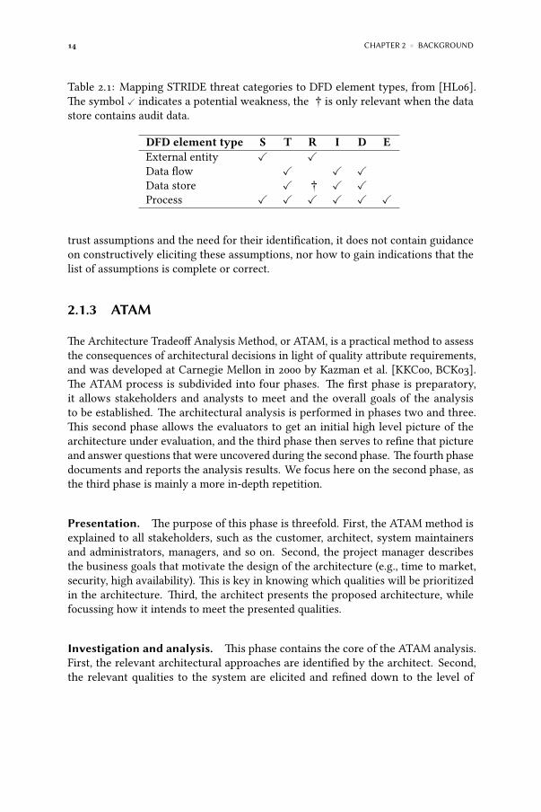
Table 2.1: Mapping STRIDE threat categories to DFD element types, from [HL06].The symbol ✓ indicates a potential weakness, the † is only relevant when the datastore contains audit data.
DFD element type S T R I D EExternal entity ✓ ✓Data flow ✓ ✓ ✓Data store ✓ † ✓ ✓Process ✓ ✓ ✓ ✓ ✓ ✓
trust assumptions and the need for their identification, it does not contain guidanceon constructively eliciting these assumptions, nor how to gain indications that thelist of assumptions is complete or correct.
2.1.3 ATAM
The Architecture Tradeoff Analysis Method, or ATAM, is a practical method to assessthe consequences of architectural decisions in light of quality attribute requirements,and was developed at Carnegie Mellon in 2000 by Kazman et al. [KKC00, BCK03].The ATAM process is subdivided into four phases. The first phase is preparatory,it allows stakeholders and analysts to meet and the overall goals of the analysisto be established. The architectural analysis is performed in phases two and three.This second phase allows the evaluators to get an initial high level picture of thearchitecture under evaluation, and the third phase then serves to refine that pictureand answer questions that were uncovered during the second phase. The fourth phasedocuments and reports the analysis results. We focus here on the second phase, asthe third phase is mainly a more in-depth repetition.
Presentation. The purpose of this phase is threefold. First, the ATAM method isexplained to all stakeholders, such as the customer, architect, system maintainersand administrators, managers, and so on. Second, the project manager describesthe business goals that motivate the design of the architecture (e.g., time to market,security, high availability). This is key in knowing which qualities will be prioritizedin the architecture. Third, the architect presents the proposed architecture, whilefocussing how it intends to meet the presented qualities.
Investigation and analysis. This phase contains the core of the ATAM analysis.First, the relevant architectural approaches are identified by the architect. Second,the relevant qualities to the system are elicited and refined down to the level of

2.1 ENGINEERING SECURE SOFTWARE ARCHITECTURES 15
scenarios. Every scenario documents a certain external stimulus, the (measurable)response that the system should generate as a reaction to that stimulus, and thearchitectural decisions that have an impact on achieving that response. Scenarios canbe subdivided in use case scenarios (i.e., involving typical uses of the system), growthscenarios (i.e., involving anticipated growth of the system), and exploratory scenarios(i.e., covering extreme changes to explore the limits of the system). The scenariosare then prioritized. Third, the architectural approaches that have been selected bythe architect to realize the quality scenarios are analyzed (e.g., a security approachthat intends to realize a security goal would be subjected to a security analysis). It isduring this step that architectural risks and potential trade off points are elicited.
As an example, Kazman et al. consider a battlefield control system in [KKC00]. Byquestioning the various stakeholders, the ATAM analyst uncover that the mainqualities of interest for this system are performance, modifyability and availability. Inorder to assist in translating qualities into testable scenarios, ATAM provides qualityattribute utility trees. These trees have a quality as their root, which then branchesinto quality attribute scenarios. Usually, these trees are elicited by the ATAM analysisteam based on information obtained by probing the stakeholders. In the battlefieldcontrol system example, the three high-level qualities are refined to the utility treeshown in Figure 2.2. While these utility trees can compile industry experience andbest practise into a reusable format, the trees are necessarily domain independentand do not provide any completeness guarantees.
48 CMU/SEI-2000-TR-004
architecture and affected the system’s performance characteristics, as we shall see. In addition to this style
• for availability, a backup commander approach was described
• for modifiability, standard subsystem organizational patterns were described
• for performance, an independent communicating components approach was described.
Each of these approaches was probed for risks, sensitivities, and tradeoffs via our style-spe-cific questions, as we shall show below.
10.2.3 Eliciting the Utility TreeThe stakeholders in this ATAM were most interested in modifiability and performance. Upon probing, however, they admitted that availability was also of great importance to them. Based upon their stated concerns and our elicitation, a utility tree was created. A portion of this is shown in Figure 13. As part of our elicitation process we ensured that each of the scenarios in the utility tree had a specific stimulus and response associated with it.
10.2.4 Analyze Architectural ApproachesAt this stage in the analysis we had in our possession a set of architectural documentation including some architectural approaches that had been identified, but we had little insight into the way that the architectural approaches actually performed to accomplish the BCS’s mission. So we used a set of screening questions and qualitative analysis heuristics to flesh out our
Utility
Performance
Modifiability
Availability
New msg format < 1 p.m.
New msg data type < 1 p.w.
Change web UI < 2 p.w.
Failure of commander nodeDiskless operation
Survive single network failure
(H,L)
(M,H)
Figure 13: A Portion of the BMS Utility Tree
Ballistics kernel computation
Inter-node message transfer(H,M)
(H,H)Response time < 1sec
Change from JVM to EJVM
HW failure MTTR < 5 min.
Figure 2.2: An example utility tree, from [KKC00].
Each quality attribute scenario is then assigned an importance for the system as awhole, as determined by the stakeholders, and an associated risk which indicates howdifficult it is to achieve this scenario. For instance, in Figure 2.2, the performanceof the subsystem that transfers messages between nodes is considered both highly

16 CHAPTER 2 ◾ BACKGROUND
important (i.e,. ‘H’) to achieve a response time under one second, while the associatedrisk of achievement is considered medium (i.e., ‘M’).
After prioritizing these scenarios based on the assigned importance and risk ofachievement values, architectural approaches can be analyzed to see whether theyaccomplish the system qualities. For instance, one identified architectural approachfor increasing the availability quality from Figure 2.2 is to have a backup commandernode to mitigate the failure of the primary commander node. The analysts thencome up with a list of questions to analyse the suitability of the chosen architecturalapproach, e.g., how the failure of a component or communication channel is detected,how a failed component is marked for replacement, and so on. These questions serveas input for the second, more in-depth, analysis phase.
Testing. This phase is essentially a second iteration of the investigation and analysisphase. It is usually performed one to two weeks after the second phase. First, the setof quality scenarios from the previous phase is extended to include extra scenariosthat might be generated by the entire group of stakeholders. The extended set ofscenarios is prioritized via voting. Second, the architectural approaches selected torealize the qualities are reevaluated (as in the ‘investigation and analysis’ phase), butthis time the new scenarios are used as test cases to evaluate them. This may resultin the identification of new risks, sensitivity and trade off points.
Reporting. The results of the analysis are collected and reported to the stakeholders.An important factor here is to report on risks, i.e., potentially problematic architecturaldecisions, and non risks, i.e., good decisions that rely on (frequently implicit)assumptions that need to be understood and explicitly recorded.
To summarize, ATAM helps in eliciting and analyzing architectural decisions ina systematic way, which allows stakeholders to trade off architectural qualities.However, as ATAM is not security centric, the guidance offered for securityassessments remains vague. For instance, there is no predefined utility tree forsecurity, forcing analysts to come up with their own interpretation (as in [RAYH09],who explicitly mention that they do not claim to have created an exhaustive securitytaxonomy). This clearly hampers the objectivity and repeatability of the analysis, andmakes it very difficult to create a completeness or correctness argument. It also makesthe success of an ATAM analysis highly dependent on the experience and expertiseof the analysts.

2.1 ENGINEERING SECURE SOFTWARE ARCHITECTURES 17
Risk Low impact Medium impact High impactHigh likelihood Low Medium High
Medium likelihood Low Medium MediumLow likelihood Low Low Low
Table 2.2: An example risk matrix, based on [GS02].
2.1.4 Risk assessment and CORAS
NIST SP 800-30 [GS02], which provides guidelines on risk management for IT systems,defines risk as a function of the likelihood of something bad happening (i.e., thelikelihood of a threat source attempting to exploit a weakness), the magnitude of theimpact should that event occur (i.e., when the weakness is successfully exploited),and the adequacy of controls that are in place to mitigate that risk. Risk is usuallysummarized in a risk matrix, such as the one shown in Table 2.2.
Based on the risk level, mitigations should be implemented as soon as possible for highrisks, mitigations should be planned in the foreseeable future for medium risks, andlow rated risks can optionally be accepted, that is, allowed to exist without mitigationsor treatments in place. According to AS/NZS 4360:2004 [Joi04], whatever risk remainsafter treatment is called residual risk. The willingness of an organization to acceptrisk is often called its risk posture.
But how is risk identified in a systematic way? We have already seen one method thathelps to elicit threats, i.e., STRIDE. However, a threat is not necessarily a risk—what ismissing is the cost of a threat being exploited, the likelihood of that happening, and theadequacy of existing controls1. One method that does exactly this is CORAS [Hog07],a graphical modelling language based on UML [Obj10] that facilitates modellingsecurity risks. The CORAS language consists of three specifications, i.e., the abstractsyntax (also known as the conceptual foundation), the graphical syntax built on topof UML, and the textual syntax which contains rules to translate a CORAS modelwith precise semantics into English.
The conceptual foundation is centered around stakeholders that assign value to assets.These assets are subject to vulnerabilities which can be exploited by threats, and giverise to unwanted incidents. A risk is then defined as an unwanted incident whichcan occur with a given likelihood and result in a specific consequence. Finally, atreatment mitigates risk. The graphical representation of these concepts is shown inFigure 2.3. Based on these concepts, a security analysis approach is then defined inseven steps.
1Note that SDL used to include a risk formula referred to as DREAD [HL06]. However, this has beenconsidered obsolete since 2005 [Epp12].

18 CHAPTER 2 ◾ BACKGROUND
8 – The CORAS language
94 A graphical approach to security risk analysis
always defined with respect to a single stakeholder. The level of risk is measured by a risk value (e.g. low, medium, high or other scales) which is based upon the estimated likelihood (a general description of frequency or probability), frequency or probabilityfor the unwanted incident to happen and its consequence in terms of damage to an asset [6]. A treatment is the selection and implementation of appropriate options for dealing with risk [55, 76].
8.1.2 The Graphical Syntax Figure 50 presents the syntactical representation of the conceptual foundation that is used in the CORAS diagrams, i.e. the graphical syntax. The stapled arrow is used for treatments, while the solid arrow is used between threats, vulnerabilities, threat scenarios, unwanted incidents and assets. The logical and/or gates are used when drawing fault trees [66] with the CORAS language.
Threat (accidental)
Threat (deliberate)
Threat (non-human)
Asset Vulnerability
and orThreat scenario
Unwanted incident Risk
Stakeholder
Logical or physical region
Treatment
Figure 50 – The graphical syntax
The graphical syntax is further described in the example driven introduction in the modeling guideline in Sect. 8.2.
8.1.3 The Textual Syntax The textual syntax of the CORAS language [36] (full details in Appendix D) has been defined for the elements in Figure 50, except for the AND/OR gates and the region. Ongoing research [21] is investigating the concept of region and this work may be included into the textual syntax in the future. Defining a textual syntax for the logical gates has so far been out of the scope of our work, but it may be a subject for future work.
To characterize the textual syntax for the CORAS language, we have used the ISO standardized Extended BNF notation [81]. The vertical bar _|_ represents options, braces {_} (respectively {_} ) means an ordered sequence of zero (respectively one) or more repetitions of the enclosed element, and square brackets [_] denotes optional features. The terminal operators are surrounded by quotes: ‘_’.
To improve readability, we do not resolve all the EBNF definitions completely into terminal operators, but stop at the level of identifier, linguistic term and numerical value.An identifier is a name or a natural language description of an element, i.e. a finite sequence of upper- and lower-case letters, numbers, spaces and punctuation marks. Its precise definition in EBNF is:
Figure 2.3: The CORAS graphical syntax, from [Hog07].
Context establishment. This phase is subdivided in three steps. The first step isan introductory meeting between the analysis team and the client, to ensure that thegoals of the analysis are clear. In the second step, the analysis team presents theirunderstanding of what they learned in the first meeting, and presents a high levelsecurity analysis to identify and fix the scope. In the third step, the target of theanalysis is additionally refined, and assumptions and preconditions are made explicit.
Risk identification, risk estimation. These two phases are organized as individualworkshops. In the first phase, the analysis team sits together with experts on thetarget of the analysis, in order to identify as many unwanted incidents, threats, andvulnerabilities as possible. An example outcome of this process is shown in Figure 2.4.In the second phase, likelihoods and consequences are assigned to the results of therisk identification phase.
8 – The CORAS language
102 A graphical approach to security risk analysis
We now explain one chain of events from the initiation caused by a threat to the left, to its impact on an asset to the right. The threat "IT-infrastructure" may first exploit the vulnerability "hardware failure" to make the server crash. Then it uses the vulnerability "poor backup solution" to initiate the threat scenario "application database fails to switch to backup solution". This threat scenario may again lead to the unwanted incident "unavailability of application", which impacts the availability of the application.
Figure 58 – Threat diagram: direct assets
To assess the indirect assets, the unwanted incidents that indirectly harm assets are specified separately (Figure 59). If they were to be modeled in the threat diagram above they would have been placed to the utmost right, but by extracting them into a separate diagram we can also include relevant incidents from other threat diagrams. Often indirect assets are of a more organizational or enterprise related kind, and therefore likely to be affected by several different types of incidents described multiple, different threat diagrams. To keep the unwanted incidents relation to their initiating threat, the threats are included in the diagram, while information about the vulnerabilities and threat scenarios are left out.
Figure 59 – Threat diagram: indirect assets
Figure 2.4: An example CORAS threat diagram from [Hog07].
Risk evaluation, risk treatment. In the risk evaluation phase, the analysis teampresents their preliminary risk findings to the client. This usually triggers adjustments

2.2 FORMAL ANALYSIS OF SECURE SOFTWARE ARCHITECTURES 19
and corrections, after which treatments are identified and evaluated by means ofdiscussion between participants. Treatments are then added to the threat diagrams.
To summarize, while the CORAS approach acknowledges the importance of makingassumptions and preconditions of an analysis explicit, no guidance is provided onhow to identify these. Additionally, the informal nature of CORAS analysis resultsprevents automated reasoning about the correctness or completeness of these results—the quality of the analysis results are therefore largely dependent on the skills andexperience of the persons involved in the analysis.
2.2 Formal analysis of secure software architectures
The brief overview of practical software engineering security approaches fromSection 2.1 highlights both the breadth of the field and its current state of the practice.While those approaches are fairly comprehensive, none of them is able to provideguarantees on the correctness of the security of the end result, or reason about thesecurity of the software system in an automated, rigorous fashion. This section brieflyoverviews formal methods for software system security. These approaches trade offthe comprehensiveness of the engineering approaches with depth and rigor of theanalysis result.
A high-level overview on the landscape of formal methods for software architecturesecurity is provided in Section 2.2.1. Section 2.2.2 documents UMLSec. Section 2.2.3goes into more detail in the Software Specification and Analysis Method. Section 2.2.4introduces the Alloy language and Alloy Analyzer tool, as that tool is relevant forthis work and will be leveraged in Chapter 3. Section 2.2.5 documents how Alloy hasbeen used in formal verification of software architectures and security.
2.2.1 An overview of formal secure modelling methods
There are many success stories of formal methods being applied to complexsystems and uncovering design issues. An early overview of industrial adoptionof formal methods by Craigen et al. [CGR95] finds that formal methods had beensuccessfully used to verify software systems ranging from the regulatory, commercialto exploratory domains. However, as the first hurdle to more widespread adoption,they identify the need for improved integration of formal methods with softwareengineering practises. Morimoto [Mor08] overviews how formal verification hasbeen successfully applied to business process modelling. Esteve et al. [EKN+12]document how they applied probabilistic model checking to verify the correctness ofthe design of a state of the art satellite platform. They conclude that full system level

20 CHAPTER 2 ◾ BACKGROUND
formal models are feasible with the current state of the art. Andronick et al. [AJK+12]document their success in verifying the seL4 operating system microkernel.
Architectural modelling techniques exist on many different levels of abstraction.Depending on their intended purpose, they range from high-level models that focuson aligning the requirement elicitation and architecture phase, to detailed models tomap architectures on hardware or detailed design.
On the requirements engineering level, it is crucial to elicit the precise requirementsthat the stakeholders expect of the system-to-be. Formal methods can help topinpoint requirements in an unambiguous way [Yu97, ELC+98, HLMN08, vL09].These requirements are then used to create a high-level software architecture. Asa bridge between the requirement space and architecture design, Grünbacher et al.[GEM04] propose a lightweight modelling approach, called CBSP (Component-Bus-System-Property). Their models are based on a small but extensible set of architecturalconcepts. They acknowledge that modelling or even partially implementing anarchitecture plays an important role in fully understanding requirements.
In architecture design as well, formal approaches have been applied successfully,either to fix the description of the architecture in an unambiguous way and checkwhether the composition is correct with respect to certain properties (e.g., [LKA+95,CCMS02, HYS+04, DCB09]), or whether the architecture upholds a specific style (e.g.,[MTWJ96]). One important aspect of architectural models is that the architect oftenonly has an incomplete view on the architecture early in the design phase. Famelis,Salay et al. [SFC12, MF12] present an approach that is able to reason with uncertaintyinherent to partial models. They conclude that well managed uncertainty can bebeneficial while introducing only minimal extra cost.
The architecture is subsequently refined down to detailed design, and eventuallytranslated to code. Again, formal methods have proven useful in showing that adetailed design specification upholds the properties of the abstract model or, in otherwords, that the detailed model is a refinement of the abstract model or specification[AL91]. Finally, formal methods can help in showing that code upholds a specification[JSP+11].
Architectural models are widely used to perform security assessments early in thedevelopment cycle. Boyd documents how secure communication can be verifiedon architectural models in [Boy93]. Luckham et al. [LKA+95] present Rapide, anapproach to specify and analyse executable architectural prototypes for propertiessuch as concurrency, synchronisation and data flow. Note that this approach islimited to analyzing a fixed list of properties, and does not lend itself well to verifyapplication specific security requirements. Sarmah et al. [SHS08] propose a latticebased classification founded on formal concept analysis using a trust based securitymodel. France et al. [FKGS04] describe a formal UML based approach to modelling

2.2 FORMAL ANALYSIS OF SECURE SOFTWARE ARCHITECTURES 21
design patterns. Eckhardt et al. [EMA+12] apply model checking to two securitypatterns for denial of service, and show that their composition leads to a new,improved pattern. Kuz et al. [KZB+12] describe a research program that builds on theresults of Andronick in [AJK+12] to enable formal verification of larger architecturesby means of so-called trusted patterns.
McUmber, Campbell et al. [MC01, CCMS02] propose a static verification approachfor security, for UML models. They accept UML class and state diagrams as input, aswell as a security property specified in their property specification language. Bothartefacts are subsequently translated to Promela and verified by the SPIN modelchecker. They conclude that linking requirements elicitation, model design andautomated verification is essential for achieving secure systems. Another securityverification approach which is built around UML, is UMLSec.
2.2.2 UMLSec
UMLSec [Jür02, Jür05, JS11] is an architectural specification and analysis methodfor security. It extends UML [Obj10] with security specific concepts which can beleveraged to verify that the model upholds specific properties, such as not leakingsensitive material (‘no down flow’), whether two parties exchange data in such a waythat cheating is impossible (‘fair exchange’), and so on. Note that this approach islimited to analyzing a fixed list of properties (i.e., secrecy, integrity and authenticity),and does not lend itself well to verifying application specific security requirements.More specifically, UMLSec extends UML with stereotypes to annotate a UML modelwith the following information.
Security requirements. These are specified on the logical level of the system. Asan example from [Jür05], a dependency from a web server to the ‘get password’interface of a client can be annotated with the stereotype secrecy, as illustrated inFigure 2.5. This signifies that for every communication link between the elements thatdepend on each other in that way, the threat scenario arising from the attacker modelassumed to hold over that link should not violate the secrecy or integrity requirementon the communicated data.
Security assumptions. These are specified on the physical level. An exampleis a communication link that is assumed to be realized by the Internet, and istherefore annotated with the Internet stereotype, as illustrated in Figure 2.5. Notethat the default attacker model specifies that Internet links uphold neither secrecynor integrity of communication. Therefore, the secrecy requirement would not holdin that example.

22 CHAPTER 2 ◾ BACKGROUND
Reclaim
Deliver
«fair exchange»Purchase
Request good
BusinessCustomer
Wait untildelivery due
Pay
undelivered
Pick up
{start={Pay}} {stop={Reclaim,Pick up}}
delivered
«Internet»
«secrecy» server machineclient machineget_password
browser access control
remote access«secure links»
client apps web server«call»
Figure 2.5: An example deployment diagram annotated with UMLSec stereotypes forsecure communication, from [Jür05].
Security policies. These govern the interactions of the different system parts. Asan example, [Jür05] documents a sales application, in which the use case diagramis annotated with the fair exchange stereotype. This fair exchange requirementcan then be additionally refined in a corresponding activity diagram of the salesprocess—actions can be annotated with the start, resp. stop tag, and executing thestart actions should eventually result in the stop actions. This can optionally bemechanically checked.
UMLSec also includes cryptographic annotations similar to those used in [NS78],which allows more complex modelling of security interactions with UML sequencediagrams. As an example, [Jür05] models a naive key exchange protocol between aclient and a server, which is then verified against an attacker model that assumes thatthe cryptographic primitives themselves can not be broken, but checks whether theinteraction itself does not contain design flaws which would allow, for instance, a‘man in the middle’ attack. Similar functionality is offered to express secure states ofobjects with state chart diagrams.
UMLSec is built on top of a formalisation of a simplified fragment of UML, whichmodels components by their input and output queues, and internal states. The securityanalysis is underpinned by an attacker model which is provided in the form of athreatsA(s) function, which maps a stereotype s on a set of actions (i.e., a subset of{read, delete, insert}) that the attackerA is able to perform on s. Attacker behaviouris then modelled by an adversary function that shows how that attacker influencescomponent input and output queues and states.
Tool support exists that enables automated verification of UMLSec models. In [Jür05],Jürjens documents three plug-ins to the overall verification framework depicted inFigure 2.6. The first leverages the Promela specification language and Spin modelchecker, and supports model checking UMLSec models that contain cryptographic

2.2 FORMAL ANALYSIS OF SECURE SOFTWARE ARCHITECTURES 23
properties such as data secrecy. That plug-in is complemented by a second plug-inthat leverages automated theorem proving by means of the TPTP notation and SPASStheorem prover. While it is more efficient, it makes extracting attack traces of insecurespecifications more difficult. That plug-in supports modeling attacker knowledge toverify data secrecy—the secrecy of an expression E from adversaries of type A isdefined asE never occurring in the knowledge set ofA during execution of the system.A third plug-in leverages the output of the second plug-in, which is in fact a set ofHorn clauses. These can then be fed to a Prolog engine, which verifies the UMLSecmodel by assigning values to these clauses, as opposed to solving them symbolically.
UML Editor(UML 1.5 / XMI 1.2 - compliant)
e.g. Poseidon 1.6
UML Model(UML 1.5 /XMI 1.2)
Analysis engineMDR
JMI
Modeland
Desiredproperties
Result
Text Report
Static Checker
Dynamic Checker
Analysis Suite
ModifiedUMLModel
Error Analyzer
“uses"
data flow
Figure 2.6: Tool support for verifying UMLSec models, from [Jür05].
To summarize, UMLSec heavily leverages UML, the de facto standard of modellinglanguages, and enriches it with stereotypes to express security properties. Thesecan then be automatically verified. However, UMLSec only allows certain categoriesof security requirements—secrecy, integrity and authenticity. Additionally, theseproperties need to be assigned to specific (sometimes detailed) elements of the

24 CHAPTER 2 ◾ BACKGROUND
architecture. This impacts the applicability of UMLSec in the early stages ofarchitectural design.
2.2.3 The Software Specification and Analysis Method
A related architectural modelling approach is the software specification and analysismethod (SAM) [WHD99, HD02, DWTB03, HYS+04]. That approach allows anarchitect to decompose and refine an architecture in such a way that certain globalproperties remain valid. It does this by subdividing a model in a structural and abehavioural part.
The structural specification. This specification is expressed in logic statements,called architectural constraints, that each of the modules and their composition mustsatisfy at every design level. The structural specification allows reasoning aboutarchitectural properties, independent of the level of abstraction. Depending on theneeds of the modeller, different logics can be used (e.g., real-time computational treelogic [WHD99] or first order linear time temporal logic [HD02]). The architecturalconstraints must be consistent.
Architectural constraints can additionally be subdivided into two categories—composition constraints and environment constraints. The former constrain theinteraction of multiple components, while the latter constrain individual componentsor connectors. Constraints are expressed over the interfaces of components, whichallows the modeller to change the design of individual components without voidingthe analysis of the entire system.
The behavioural specification. For every element that makes up an architecture(i.e., components and connectors), their behaviour is specified by means of aPetri net. This makes the architectural model executable. Again, depending onthe needs of the modeller, different types of Petri nets can be used (e.g., real-time Petri nets [WHD99] or predicate transition nets [HD02]); however, the Petrinet specification should be compatible with the chosen structural specificationlogic. The behavioural specification of every architectural element must upholdthe corresponding architectural constraints.
As shown in Figure 2.7, an architectural model in SAM is inherently hierarchical. Thestructural specification goes in lockstepwith the refinement of the architectural design.For every refinement step, the refined architecture must inherit all ports associatedwith the abstract architecture, and must uphold all constraints of the abstractarchitecture. The authors of SAM claim that because of this iterative refinement,every architectural decision can be traced back to the original requirements and,

2.2 FORMAL ANALYSIS OF SECURE SOFTWARE ARCHITECTURES 25
Fourth, SAM needs to be understandable and usable.To realize these features, we introduced hierarchicaldecomposition. The visual structure and the simplecontrol flow mechanism of Petri nets are certainly veryhelpful. Furthermore, we restrict that the propositional/predicate symbols used in temporal logic specificationsbe only the ports defined in Petri net models. This re-striction significantly simplifies the resulting temporallogic specifications such that they are easy to write andunderstand. Furthermore, we use as much software toolsupport as possible in both developing and analyzingSAM specifications.
2.1. Visualizing the structures of software architectures
In SAM, a software architecture is visualized by ahierarchical set of boxes with ports connected by di-rected arcs. These boxes are called compositions. Eachcomposition may contain other compositions. The bot-tom-level compositions are either components or con-nectors. Various constraints can be specified. Thishierarchical model supports compositionality in bothsoftware architecture design and analysis, and thus fa-cilitate scalability. Fig. 1 shows a graphical view of anSAM software architecture, in which connectors are notemphasized and are only represented by thick arrows.
Each component or connector is defined using a Petrinet. Thus the internal logical structure of a componentor connector is also visualized through the Petri netstructure.
Textually, an SAM software architecture is definedby a set of compositions C ! fC1;C2; . . . ;Ckg (eachcomposition corresponds to a design level or the conceptof sub-architecture) and a hierarchical mapping h re-
lating compositions. Each composition Ci ! fCmi;Cni;Csig consists of a set Cmi of components, a set Cniof connectors, and a set Csi of composition constraints.An element Cij ! "Sij;Bij#, (either a component or aconnector) in a composition Ci has a property specifi-cation Sij (a temporal logic formula) and a behaviormodel Bij (a Petri net). Each composition constraint inCsi is also defined by a temporal logic formula. Theinterface of a behavior model Bij consists of a set ofplaces (called ports) that is the intersection among rel-evant components and connectors. Each propertyspecification Sij only uses the ports as its atomic prop-ositions/predicates that are true in a given marking ifthey contain appropriate tokens. A composition con-straint is defined as a property specification, however itoften contains ports belonging to multiple componentsand/or connectors. A component Cij can be refined intoa lower-level composition Cl, which is defined byh"Cij# ! Cl.
2.2. Modeling the behaviors of software architectures
In SAM, the behavior of a component or a connectoris explicitly defined using a Petri net. The behavior of anoverall software architecture is implicitly derived bycomposing all the bottom-level behavior models ofcomponents and connectors. SAM provides both themodeling power and flexibility through the choice ofdi!erent Petri net models. We have used several Petri netmodels including time Petri nets (Wang et al., 1999),condition event nets, and predicate transition nets (Heand Deng, 2000, 2002) in our previous work. The se-lection of a particular Petri net model is based on theapplication under consideration. A simple Petri net
Fig. 1. An SAM software architecture.
X. He et al. / The Journal of Systems and Software 71 (2004) 11–29 13
Figure 2.7: Overview of an architectural model in SAM, from [HYS+04].
conversely, the impact of the requirements on the subsequent refinements can beseen.
To summarize, SAM focusses on creating a formal architectural representationfor simulation, reachability analysis, model checking and interactive proving ofarchitectural properties. While it does have a related concept to trust assumptions,i.e., environment constraints, SAM does not help in eliciting assumptions directly.
2.2.4 A brief introduction to Alloy
Alloy [Jac02, Jac06] is a formal modelling language based on first order logic andset theory, heavily inspired by Z [Spi89]. The Alloy Analyzer is a constraint solverthat provides fully automatic simulation and checking by finding model instancesthat correspond to a certain model description. Furthermore, the analyzer is ableto automatically verify model properties and visualise counterexamples. The Alloylanguage is explicitly designed to make it easy to build models incrementally and,according to its author, was influenced by modelling languages such as the objectmodels of OMT and UML. This makes it a prime candidate for our intended purpose,i.e., modelling software architecture design. While we have considered alternativemodel finders, it turns out that the Alloy approach is a reasonable efficient choice forour intended purpose (as we will see in Chapter 4).

26 CHAPTER 2 ◾ BACKGROUND
As a small illustration of the syntax and semantics of the Alloy language, considerthe following. There are servers that host web pages, and clients can connect to thoseservers and retrieve pages. However, we only want servers to serve pages to clientsthat are properly connected to that server, and only when the client is authorized.This situation can be modelled in Alloy as follows. First, we begin by introducingsome types (or ‘sigs’ in Alloy parlance).
Listing 2.1: Defining new types in Alloy.
1 // A page represents content that is hosted by a server.2 sig Page {}3
4 // A client connects to a server to retrieve pages.5 sig Client {6 connected: lone Server7 }8
9 // A server hosts a set of pages to its connected clients.10 sig Server {11 hosts: set Page,12 authorizedClients: set Client13 }
Of these three types, Page2 is a simple atomic type without internal structure, andClient and Server each contain fields (that is, relations) that interrelate those types toeach other. For instance, the field connected: lone Server signifies that every Client hasan attribute connected, which refers to zero or one Server. We can now define whatwe mean by “connected clients can retrieve pages”. This is encoded as a predicatedefined on the Server as follows.
Listing 2.2: Defining predicates in Alloy.
14 // Definition of the retrieve operation on a server.15 pred Server.retrieve(c:Client,p:Page) {16 c in this.authorizedClients17 p in this.contents18 }
This predicate, which represents the retrieve operation, accepts two arguments: aClient c and a Page p. The predicate is true when c is authorized, i.e., a member of thethis.authorizedClients relation where this is the Server to which the retrieve request wasmade, and p is a member of the this.contents relation. We can now express the propertywe want our model to uphold: whenever a client retrieves a page from a server, then
2From now on, modelling concepts are typeset in this font.

2.2 FORMAL ANALYSIS OF SECURE SOFTWARE ARCHITECTURES 27
that client is connected to that server and the client is authorized according to thatserver.
Listing 2.3: Defining and verifying properties in Alloy.
19 // Whenever a client retrieves a page, that client and the server are connected.20 assert Requirement {21 all c:Client, s:Server, p:Page {22 s.retrieve[c,p] implies c.connected = s and c in s.authorizedClients23 }24 }25
26 check Requirement for 3
An assertion is a predicate that can automatically be verified to hold by the AlloyAnalyzer. In order to do this, the modeller has to provide a so-called scope. Forinstance, here, the requirement is to be checked for a scope of three. This impliesthat all combinations of up to three Client, Server and Page instances will exhaustivelybe verified by the Alloy Analyzer to uphold the Requirement predicate. In this case,as depicted in Figure 2.8, the property does not hold, and the analyzer visualizes acounterexample that violates the requirement.
Figure 2.8: Verifying the example requirement.

28 CHAPTER 2 ◾ BACKGROUND
The counterexample is an instantiation of our model where the client c belongs tothe authorizedClients of server s; however, c is not connected to s. In other words, themodel does not enforce that the client is connected to the right server. This can bemitigated by either reworking the original model, or by adding a fact as follows. Thisfact enforces that whenever a server considers a client to be authorized, that client isconnected to that server.
Listing 2.4: An example fact.
27 fact ConnectIsSymmetric {28 all s:Server, c:Client | c in s.clients implies c.connected = s29 }
Given this fact, no more counterexamples are found and the Alloy Analyzer declaresthat the assertion may be valid—indeed, it is still possible that counterexamples existin larger scopes. However, one of the underlying principles of model finding, theso-called small scope hypothesis, claims that most counterexamples are found in areasonably small scope [Jac06]. And the upside of this inherent incompleteness isthat the Alloy Analyzer is able to reason about partial, incomplete models. This makesit very suitable for modelling software architectures, as we will see in the remainderof this work.
2.2.5 Automated verification with the Alloy Analyzer
Given that the Alloy language was created explicitly to model software design, itshould come as no surprise that model finding by means of the Alloy Analyzer hasgained the attention of the software architecture modelling community. Kim et al.[KG06] present an approach to analyze architectural styles for properties such asconsistency, composability, and refinement. In their work, an architectural modelconsists of components, connectors, configurations of these elements, and theirproperties (such as priority or CPU usage, latency, and reliability). Merle et al. [MS08]formally model the Fractal component model (Bruneton et al. [BCL+06]) in Alloy,as it allows for lightweight modelling and rapid iterations between modelling andverification.
Alloy has also been used to create models of security mechanisms. Lin et al. [LBC10]use Alloy to model and verify partial attacks against cryptographic systems. Theirapproach comprises two variants—one that reasons about entropy, and anotherthat reasons about possibility sets. Hashii [Has04] applied Alloy to model theDARPA Polymorphous Computing Architecture (PCA), an architecture for solvingthe multilevel security problem. They also document running into the so-called statespace explosion problem, where their model needed to be sufficiently abstracted insome areas as the Alloy Analyzer would crash with an out of memory exception on
2.3 CONCLUSION 29
larger models. We will also run into this problem, and show how it can be mitigated,in Chapter 4. Chen et al. [CGKP06] use first order epistemic logic to encode andverify a general security model in Alloy. Their security model contains properties ofsecure communication, such as message integrity, confidentiality, authentication andnon repudiation.
Akhawe et al. [ABL+10] leverage Alloy to create and verify a model for web security.De Ryck et al. [DRDJP11] use themodel from [ABL+10] tomodel and verify their client-side protection mechanism against CSRF attacks. In that work, they systematicallyextend the Akhawe model to make it more realistic, in a way that could be interpretedas an ad hoc application of the approach we present in this work.
2.3 Conclusion
Securing a software system is an inherently complex problem that permeates thewhole software life cycle and brings together viewpoints that range from theorganizational to the physical level, and from a regulatory to the implementationlevel. Engineering methods for software security are generally developed with thislife cycle in mind, but tend to trade off analysis depth for practical applicability.While they acknowledge the important role that trust assumptions play in thesecurity of a software system, they lack support to elicit and reason about theseassumptions, which are crucial for assessing the security of a software architecture.In Microsoft’s SDL approach, the risk analysis phase explicitly mentions the needfor documenting external security notes and security assumptions before startingthe STRIDE approach, but provides no constructive guidance on how to do this.ATAM also mentions the need to document architectural decisions, and especially theoften implicit assumptions on which they are built. The CORAS approach yet againmentions the need to make assumptions and preconditions explicit on which the restof the analysis is based, before the risk identification and estimation phase. Again, noconstructive guidance is provided. Finally, none of these methods provides any sortof completeness argument, and the breadth of uncovered security issues is largelydependent on either predefined checklists (e.g., the STRIDE table and ATAM utilitytrees) or the skills and experience of the security expert (e.g., during brainstormingsessions in both ATAM and CORAS).
Formal methods for software security, on the other hand, are usually scoped to asingle point in the software life cycle. What they lack in breadth, they make up indepth. As it is possible to formally reason about the results of a formal analysis, it isalso usually easier to verify the relevance of the analysis results and verify the impactof an uncovered issue on the entire system through simulation. However, there existsa disconnect between formal methods and practical engineering-oriented methods.

30 CHAPTER 2 ◾ BACKGROUND
Usually, formal methods are risk agnostic. This limits their integration in the ‘bigpicture’ of enterprise risk management processes. Also, this tends to quietly ignorethat no security solution is perfect, and it is impossible to reduce residual risk to zero.Formal methods could, in theory, provide explicit support for both uncovering andreasoning about trust assumptions. However, this support is not fully realized incurrent approaches. The SAM approach does not mention assumptions explicitly, buthas a very related concept in environment constraints in a structural specification.UMLSec has an explicit notion for security assumptions. However, these assumptionslimit themselves to predefined stereotypes on the physical level. While UMLSec doesnot contain constructive guidance on how to elicit these assumptions, it does providecapabilities to verify whether the security functionality of the system matches theseassumptions.
The next chapter presents a formal architectural modelling technique that takes afirst step in bridging this gap.

CHAPTER 3Security centric modelling of
software architectures
This chapter presents the first contribution of this dissertation—an approach to analyzethe security of software intensive system architectures. We start from the observationthat security analysis methods can provide correct yet meaningless results if theassumptions underlying the model do not conform to reality. Therefore, we focuson making these underlying assumptions explicit, so that they can be taken intoaccount. The approach is designed to be used by (and usable for) the softwarearchitect. Its semantics deliberately stay close to standard architectural conceptssuch as components and connectors, yet it is easily extended with domain specificconcepts. It can be applied early on in the architectural design phase, is iterativein nature, and can handle partial models and incomplete information. It can easilybe integrated in a larger software development process, and the interactions withdifferent stakeholders are made explicit.
3.1 Introduction
Automated analysis on formal models of software architectures can uncover gaps, asillustrated in the simple client-server example from Section 2.2.4. When this kind ofanalysis is applied in a security setting, the uncovered gaps correspond to weaknessesthat the architect did not anticipate. However, how do we know that the model itselfis realistic, and the uncovered results useful? The example model in Section 2.2.4 isclearly too abstract to use the verification results in the security assessment of theauthorization process of a real web server. Because of that naive model, the analysisnever takes situations such as network failure or unreliable connectors into account,or even hints at the example trust assumption from Section 1.2, i.e., that passwords
31

32 CHAPTER 3 ◾ SECURITY CENTRIC MODELLING OF SOFTWARE ARCHITECTURES
should not be cached and should be protected from “phishing” attacks. How to createsufficiently realistic models that are of use to the software architect is the topic ofthis chapter.
This chapter presents a formal architectural modelling and analysis method thathelps the software architect to iteratively construct the set of assumptions (calledthe context) which is required by the system to operate correctly. We provide ananalysis method that formally verifies that the system model upholds the securityrequirements in light of the stated assumptions. The context can be used as an explicittarget of assessment in a risk management process. It refines the important, yet vaguequestion “Is my system secure?”, to a more practical one, “Is the expected contextmatched by reality?”. Additionally, the context serves as a checklist of propertiesthat the deployment environment should uphold for the application to be deployedsecurely.
Accept?(add an assumption)
Mitigate?(refine/extend model)
Verify the model
Identify and assess weakness
Relaxinstance-level
constraints
Counter- example?
12
Model description(soware architecture)
Assumptions(context)
Assertions(security requirements)
Figure 3.1: An overview of the approach. The black rectangles denote the inputs tothe methodology, the arrows denote the different steps.
A number of approaches exist to assist in (semi-) automatically verifying models,including assisted theorem proving, model checking, and model finding. Central toour approach is the technique ofmodel finding. As opposed to theorem proving, modelfinding enables completely automated verification of properties and the visualisationof both positive instances (i.e., witnesses or illustrations) and negative instances(i.e., counterexamples) of a theory, at the cost of only providing guarantees that theproperty holds for relatively small model instances. Theorem proving, on the otherhand, provides universally valid results at the cost of requiring more effort—whilethere is software to assist in creating proofs, no fully automated theorem prover forsufficiently expressive logics exists. Illustrating positive or negative model instanceswith theorem provers is also not straightforward. We deliberately trade off thestronger guarantees of theorem proving for the increased usability of model finding.
Another widely used verification technique is model checking. In model checking,

3.1 INTRODUCTION 33
temporal properties are verified to hold on finite models, that is, models with afinite amount of states. Model checking takes into account all explicitly modelledstate transitions, visits the reachable states and checks whether the property underobservation holds. The models created in model checking can be seen as graphs ofstates connected by explicitly modelled transitions. Model finding, on the other hand,does not depend on the explicit modelling of transitions—if certain model behaviouris not prevented by a constraint in the model, model finding will take it into account.Therefore, models created with model finders can initially be seen as fully connectedgraphs in which all transitions between states are possible. Adding constraints to amodel removes some of these transitions. This way of modelling, where the modellerdoes not need to explicitly add transitions that express what an attacker could do, canpotentially help in uncovering more attacker behaviour. However, care needs to betaken that no overly strong constraints are added to the model. In order to preventthis from happening, we leverage model relaxation to fully realize the potential ofmodel finding in uncovering more potential attacker behaviour.
Our approach is illustrated in Figure 3.1. It uses the Alloy model finding approach toboth create and verify models. First, an Alloy model of the software architectureis created (which is supposed to contain at least information on the systemdecomposition, the deployment description and the functional scenarios). Dueto the nature of model finding, this model of the architecture does not have tobe complete; the architect can start early in the architecture design phase withsmall models, and iteratively refine them. The model is created in accordance to anarchitectural meta model which provides reusable domain independent abstractionssuch as components, connectors, and so on. The security requirements are alsoformally modelled as Alloy assertions. While verifying the architectural model againstthe security requirements, a context is iteratively built which contains a formalizationof all the assumptions that are necessary for the requirements to be realized. Thecontext is constructed by iterating over all automatically generated counterexamplesthat violate the requirements of the modelled architecture, debunking the implicitassumptions that made these scenarios feasible, and explicitly adding constraints tothe context to prevent these counterexample from occurring (see arrow 1). Theseconstraints represent the expectations on the deployment environment (e.g., thesecurity guarantees provided by the middleware), on the third party security solutionsintegrated in the architecture (e.g., an authorization engine), and on the internal partsof the system that are not explicitly modelled at the current level of refinement.
Every constraint in the context documents something that the architect explicitlytakes for granted in the current formal model. It is then up to the security engineerto accept these assumptions, or to suggest security mechanisms with which thearchitecture can be extended so that the assumption becomes superfluous (see arrow2). Note that, as the abstractions in the Alloy model (which are also used in thecounterexamples) are very close to standard architectural abstractions, it is relatively

34 CHAPTER 3 ◾ SECURITY CENTRIC MODELLING OF SOFTWARE ARCHITECTURES
easy to interpret the counterexamples and to map the results of the analysis backto the actual issues in the architectural model. Therefore, the proposed approachprovides constructive support to the architect as well.
This chapter is structured as follows. Section 3.2 describes our architectural metamodel, introduces Alloy as the target formalism for our analysis, and shows howarchitectural descriptions are mapped to Alloy. Section 3.3 introduces modelrelaxation and its impact on verifying the system security requirements. The analysisprocess, the iterative construction of the context, and the stakeholders that areinvolved in the analysis are outlined in Section 3.4. The types of weaknesses that canbe discovered are discussed in Section 3.5. We conclude in Section 3.6.
3.2 Ingredients for formallymodelling architectures
In order to create a formal architectural model, we leverage information from differentarchitectural views, as documented in Section 3.2.1. These architectural views are thensystematically encoded in Alloy by mapping them to an architectural meta model thatwe have created. This meta model is documented in Section 3.2.2. How we expressand verify properties on the resulting formal architectural model is discussed inSection 3.2.3. We conclude with some final remarks on the meta model in Section 3.2.4.
The approach is illustrated on a model of an online shop. This shop allows customersto purchase items via their webbrowser. Items can be added to a virtual shopping cart,after which the user checks out and the cost is calculated. The customer then pays forthe transaction. We focus on one security requirement, which states that successfullycompleted transactions should be logged by the shop in a secure (i.e., tamper proof)way. In other words, it should be impossible to either alter a logged transaction ordelete it, without the alteration being detected. The initial architecture of the shop isdocumented next.
3.2.1 Important architectural views
Software architectures are documented in terms of different views, with each viewconsisting of one or more models [ISO11]. For the purpose of security analysis,we propose a meta model (based on the “4+1” views from Kruchten [Kru95]) thatincorporates information from the physical, logical and scenario view. Informationfrom the development view is disregarded, as we focus on the security of a systemrunning in a specific deployment environment and less on how the system is to beconstructed. While our approach does not require precisely these views (based onavailable architectural documentation, less or more information could be included

3.2 INGREDIENTS FOR FORMALLY MODELLING ARCHITECTURES 35
(a) Logical view.
(b) Physical view. (c) Scenario view.
Figure 3.2: Different views on the online shop, using UML notation.
in the analysis), we find that they are a practical choice, given the wide acceptanceof the “4+1” model on which they are based. The views specific to the online shopillustration are shown in Figure 3.2 using UML notation [Obj10].

36 CHAPTER 3 ◾ SECURITY CENTRIC MODELLING OF SOFTWARE ARCHITECTURES
The logical view captures the components comprising the system. As shown inFigure 3.2a, the logical view of the online shop consists of a Shop component, whichrealizes the functionality expected by the shop’s customers, and a Logger component,which realizes the security requirement imposed on the transaction log, i.e., that nologged entry can be modified or deleted without detection. Such a solution could havebeen selected from a catalog of security mechanisms, such as the Secure Loggersecurity pattern from [SNL05]. The Logger exposes two interfaces, one public LogIFwhich is used by components that need to log messages, and a private LogAdminIFwhich is used by the AdminConsole. The AdminConsole component represents thedashboard that the shop administrator uses to read the log, and to verify that it isstill intact. The main purpose of including information from the logical view in themodel is to enable the functional modelling of the system (i.e., to create a model thatsimulates the behaviour of the final system, up to a certain level of abstraction). Thelogical view does not help in uncovering security weaknesses directly, but providesthe scaffolding on which the information of the other two views is grafted.
The physical view describes the mapping of the software onto the hardware andreflects its distributed aspects. In Figure 3.2b, three nodes are relevant to the shoppingsystem. The customer’s browser device (hosting the browser process which is notdepicted) is attached to the server (hosting both the Shop and the Logger process)via the Internet. The Shop and Logger are connected via a local connector, which wemodel as a link, since UML2 lacks explicit connector semantics. The AdminConsoleexecutes on the administrator’s desktop, and is connected to the server via a privateintranet. The physical view is the main driver of the security analysis process. Theinformation contained therein allows reasoning about security issues such as data andcommunication integrity, data flow properties, availability of nodes and links, andthe introduction of malicious entities in the deployment environment. For instance,Figure 3.2b allows the analysis to reason about data flow between the customer’sbrowser and the Shop, as it shows where these processes are hosted and whichcommunication channels are available to exchange this data.
The scenario view illustrates how the elements in the other views work together bythe use of a small set of important scenarios, which are instances of more generaluse cases. Figure 3.2c captures the scenario of buying an item from the Shop. Thecustomer adds items to the shopping cart, after which the cart is checked out. TheShop calculates the total cost, and returns this to the customer. The customer paysthe specified amount, after which the transaction is logged by the Shop via the Logger.This view builds upon the foundations in the logical view to allow reasoning aboutwhat the system should do. It shows which model elements are relevant for theexecution of a system operation and enables tracing the impact of low-level securityproperties to a global impact on the functionality of the system. For instance, theimpact of the inability of the Logger to logmessages is made clear in Figure 3.2c, whichshows that the Log operation is used in the implementation of the Pay operation of

3.2 INGREDIENTS FOR FORMALLY MODELLING ARCHITECTURES 37
the online shop. In general, the scenario view allows reasoning about architecturalsecurity properties such as full mediation (e.g., that all requests are routed throughan enforcement point), ordering of operations (e.g., that payment precedes shipping)and timing issues (e.g., race conditions).
3.2.2 Integrating architectural views in a meta model
We focus on creating architectural models in Alloy that are semantically close tothe industrial practise, i.e., containing an UML-like vocabulary. We facilitate this byproviding an architectural meta model, depicted in Figure 3.3, that incorporates thethree architectural views described in Section 3.2.1. Note that the cardinalities in thismeta model are deliberately kept underconstrained (e.g., an Invocation can be receivedby a Component, but does not have to be). We will come back to this in Section 3.2.4.
univ
Invocation
Operation
Connector
Component
Interface
Link
Node
args
0..∗
of
1
receivedBy
0..∗
calledBy 0..1
buffers0..∗ connects
0..∗
methods
0..∗ realizedBy
0..∗
connects
0..∗
hosts
0..∗
Figure 3.3: Our architectural meta-model (using UML syntax).
The concepts presented in the meta model represent a proper subset of UML that weexpect the architectural description to adhere to. A software architecture as describedin Section 3.2.1 is mapped to our Alloy meta model as follows. The mapping of logicaland physical elements is straightforward. An architectural component, interface andoperation are mapped to their namesake types in Alloy, as are UML nodes and links.Architectural connectors are a bit more problematic, as there is no correspondingconcept in UML. We assume that a Connector must be present between two (or more)Components, i.e., connect those Components, before they can interact. Furthermore,if a Connector exists between Components on different Nodes, then there must be acorresponding Link between those Nodes to host the Connector. These assumptionsare sufficiently generic that they are applicable to a wide range of component basedsystems, as we will see in Chapter 6.
A complete presentation of our Alloy meta model is included in Appendix A. As anillustration, the modelling process is applied to the parts of Figure 3.2 marked by adashed rectangle.

38 CHAPTER 3 ◾ SECURITY CENTRIC MODELLING OF SOFTWARE ARCHITECTURES
Concerning the logical view (c.f. Figure 3.2a), the Logger and Shop components aremodelled as follows. Note that all the types from Figure 3.3, such as Component,Invocation and Node are defined in the meta model and largely omitted here for brevity.Specific parts from the meta model are repeated where required.
Listing 3.1: Introducing the Logger component in Alloy.
30 sig Logger in Component { } // Every Logger is a Component (‘in’ denotes a subset relation).31
32 sig Shop in Component {33 logger: Logger one→Time // ‘logger’ is an attribute of Shop.34 // It contains a reference to a logger−instance.35 }36
37 sig Log in Operation { } // Log is an operation.38
39 sig LogIF in Interface { } { // LogIF is an interface.40 // The LogIF is realized by the Logger, and contains only one method (i.e., ‘Log’).41 // The methods and realizedBy relationships are defined in (and inherited from) Interface.42 methods = Log and realizedBy = Logger43 }
Before the Shop and Logger components can be detailed, we need to define the typesthat are used in their definition. As shown in the definition of LogIF (line 42), thisinterface contains the method Log and is realized by Logger. This operation acceptsand processes Messages. Internal to the Logger component, a logged message isrepresented in a different format (e.g., a sequence number is added). These additionaldetails can be derived from the description of the adopted solution (e.g., the SecureLogger pattern [SNL05]). To this aim, the ProcessedMessage type is introduced(line 44). According to a similar rationale, the SignedMessage type (which denotes adigitally signed ProcessedMessage) must be introduced as well (line 52). It containsa reference to the current ProcessedMessage (line 53), the signedContent (line 54), i.e.,the ProcessedMessage that was originally signed, as well as the Principal that signedthe message (line 55). A SignedMessage is valid at a certain point in time when thecontent matches the signed content, and it was signed by the LoggerEntity. This iscaptured in the isValid predicate on line 60. Note that the above Alloy description ofthe Secure Logger pattern could be provided to the architect via a library, as we willsee in Chapter 5.
Listing 3.2: Introducing domain-specific types used by the Logger.
44 sig ProcessedMessage {45 // ‘content’ is a relation from one Message to Time atoms.46 // Note that the arrow defines a relationship from the type on the left to the type on the right.47 content: Message one→Time,48 // Similarly, ‘id’ is a relation from one integer to time.

3.2 INGREDIENTS FOR FORMALLY MODELLING ARCHITECTURES 39
49 id: Int one→Time50 }51
52 sig SignedMessage {53 content: ProcessedMessage one→Time,54 signedContent: ProcessedMessage one→Time,55 signedBy: Principal one→Time56 }57
58 // This defines a predicate on instances of SignedMessage, with one Time ‘t’ as argument. Note that,59 // as in Java, the current instance is accessible with the keyword ‘this’.60 pred SignedMessage.isValid(t:Time) {61 // In Alloy, relationships can be navigated using the ‘.’ operator (i.e., . signifies a relational join).62 // For instance, ‘this.content.t’ denotes the current content of a SignedMessage, which is a63 // ProcessedMessage. The second ‘.content.t’ denotes the current content of that ProcessedMessage, which64 // is a Message.65 this.content.t.content.t = this.signedContent.t.content.t66 this.signedBy.t = LoggerEntity67 }
Now that the necessary types have been introduced, the previous definition of theLogger can be completed with the attribute shown in Figure 3.2 (i.e., a mutable list ofsigned messages) as follows.
Listing 3.3: Defining the internals of the Logger.
68 sig Logger in Component {69 // ‘contains’ attributes a variable list of SignedMessage instances to every Logger instance.70 contains: set SignedMessage→Time71 }
Alloy does not have a built-in notion of time. Therefore, time is explicitly modelledas a set of discrete, ordered Time instances. Associations (such as the set of nodesconnected by one link) can be made mutable by adding a relationship with the Timeset (i.e., the connects relationship that relates Node to Link in Figure 3.3 is a relationshipfrom Node over Link to Time, or Node→Link→Time).
Central to the scenario view is the Invocation, which can be created by the callingcomponent (i.e., invoked) and consumed by the receiving component (i.e., executed).Once an invocation is invoked, it is buffered in a connector. When it is consumed bythe receiving component, it is removed from the connector.
Listing 3.4: Definition of the Invocation type, from the meta model.
72 sig Invocation {73 of: one Operation, // The operation being invoked.

40 CHAPTER 3 ◾ SECURITY CENTRIC MODELLING OF SOFTWARE ARCHITECTURES
74 args: set univ, // The arguments of the invocation.75 caller: lone Component, // The caller, as expressed ‘on the wire’.76 orig_caller: one Component, // The component that sent the original invocation.77 receivers: set Component, // The receiving components.78 invoked: lone Time, // The time of invocation (if any).79 executed: lone Time // The time of execution (if any).80 }
An equivalence relationship is defined between invocations with identical senders andreceivers, the same operation, and the same invocation time. This allows analyzingsituations where an invocation is swapped for an equivalent one, e.g., one with thesame logical caller (line 76) but actually sent by a different physical caller (line 75), asis the case when an invocation is routed through different intermediary components,for instance.
Every operation is coupled to its behavioural specification by adding an extra factto the model1. In architectural terms, this corresponds to associating a requestreceived at a component interface to the internal implementation of such an operation.For instance, consider the Logger which offers a Log operation. Suppose that thespecification of the Log operation is contained in the predicate Logger.write, then theLog operation is coupled to this specification as follows (note line 102).
Listing 3.5: Coupling the Logger interface to its behavioural specification.
81 pred Logger.log(m:Message, t:Time) {82 // ‘some’ represents existential quantification in Alloy.83 some pm:ProcessedMessage, s:SignedMessage {84 pm.content.t = m and s.content.t = pm85 s.sign[LoggerEntity,t] and s in this.contains.t86 }87 }88
89 pred Shop.pay(…) {90 …91 // A client of the Logger invokes the Log operation by means of the Invoke predicate,92 // defined in the meta model.93 Invoke[this,this.logger.t,Log,m,t]94 }95
96 sig Logger in Component {97 …98 } {99 // ‘all’ represents universal quantification.
1Note that, since Alloy does not offer reflection, it is not possible to couple the behaviour of an operationdirectly to the instance of an Operation model element.

3.2 INGREDIENTS FOR FORMALLY MODELLING ARCHITECTURES 41
100 all t:Time | some c:Component,arg:univ |101 // The Execute predicate is true whenever a corresponding Invocation is executed.102 Execute[c,this,Log,arg,t]⇒ this.log[arg,t]103 }
The Shop is now able to invoke the Log operation by calling the Invoke predicate, withm the message contents, and t the current time instance, as shown on line 93. TheInvoke predicate, as part of the meta model, then creates an appropriate Invocationwith the time stamp ‘invoked’ initialized to t. That Invocation is then buffered in aconnector, as follows.
Listing 3.6: Semantics of invoking an invocation, from the meta model.
104 pred Invocation.invoke {105 // If there is a time when this invocation is invoked, then…106 some this.invoked⇔ {107 // The original calling component is connected to (at least) one connector108 // to pass the invocation on. The invocation will only be buffered in one109 // connector.110 let conn = { c:Connector | this.orig_caller in c.connects.(this.invoked) } {111 one c:conn {112 // There is a new corresponding invocation buffered by the connector.113 this in c.buffer.(this.invoked)114 // If there is a time before this.invoked (i.e., this.invoked differs from the first time tick),115 // then this invocation was not previously buffered in the connector.116 (this.invoked) ≠ TO/first⇒ this not in c.buffer.((this.invoked).prev)117 }118 }119 }120 }
This snippet of Alloy specification states what it means for an invocation to be‘invoked’. At the time of invocation (if any), the invocation is placed in the buffer ofa connector connected to the calling component. Similarly, but not shown here, thatinvocation would be removed from the buffer of the connector at execution time. Thedefinition of a connector is as follows.
Listing 3.7: Definition of connector, from the meta model.
121 sig Connector {122 // The set of components connected by this connector123 connects: set Component→Time,124 // The set of invocations buffered by this connector125 buffer: set Invocation→Time126 }{127 // Connectors have to be supported by a physical communication path

42 CHAPTER 3 ◾ SECURITY CENTRIC MODELLING OF SOFTWARE ARCHITECTURES
128 all disj c1,c2:Component,t:Time | c1 + c2 in connects.t implies129 some n1,n2:Node {130 c1 in n1.hosts.t and c2 in n2.hosts.t131 n1 = n2 or some l:Link | n1+ n2 in l.connects.t132 }133 }
The connections on line 106 and 128 relate the role of the different physical and logicalelements of the architecture to the correct realisation of the use cases. Conversely,this also links the impact of the failure of each of the architectural elements backto the correct operation of the system as a whole. For instance, consider the casewhere no physical communication path (i.e., a ‘link’) exists between two nodes. Thenthere can not be a logical connection (i.e., a ‘connector’) between the componentsdeployed on these nodes and, conversely, no invocations can be exchanged betweenthese components.
The architect can instruct the Alloy Analyzer to generate instances of the model withthe command run {} for 3. This will visualise arbitrary model instances within a scopeof 3 (i.e., with a maximum of three component instances, three connector instances,three times, etc.). Larger scopes allow reasoning over more complex instances, whileincreasing analysis overhead. By checking that the model still has instances withinthe current context, the architect can verify that the model is realizable (i.e., thatthere are no internal contradictions). This check enforces that applying our approachresults in consistent models.
3.2.3 Expressing and verifying security requirements
Supposing that the rest of the system of Figure 3.2 is similarly modelled, it is nowpossible to express and verify the security requirements of the Logger. We assume thata security requirement is expressed as constraints on the behaviour that is observablefrom the interface exposed by the respective component. This approach is similar toSAM, as summarized in Section 2.2.3, and allows the architect to change the design ofindividual components without voiding the analysis results of the entire system—thisis handled in depth in Chapter 4. The integrity requirement that messages written tothe log should not be deleted, is modelled as an assertion. Assertions are similar toregular predicates, but they can be automatically verified by the Alloy Analyzer.
Listing 3.8: Expressing a security requirement of the Logger.
134 assert NoDeletion {135 all t:Time,m:Message,s:Shop | Invoke[s,s.logger.t,Log,m,t] implies (136 some t1:t.nexts + t {137 all t2:t1.nexts + t1 | (s.logger.t2).verify[1,t2] implies

3.2 INGREDIENTS FOR FORMALLY MODELLING ARCHITECTURES 43
138 (s.logger.t2).read[m,1,t2]139 }140 )141 }
Note that the read and verify predicates represent the implementation of the Read, resp.Verify operations. The predicate read is true if the specified second argument (‘1’ for‘true’, ‘0’ for ‘false’) corresponds with that processed message being present in thelog at that time, and verify is true whenever the first argument (again, ‘1’ for ‘true’,‘0’ for ‘false’) matches the perceived status of the log. In other words, the NoDeletionrequirement asserts that an invocation from a Shop of the Log operation on its Loggerresults in a correct state of that Logger.
The architect can verify whether the NoDeletion requirement holds with the commandcheck NoDeletion for n, which would exhaustively explore every model instancewithin a scope of n. If it does not hold, a counterexample can be visualised.This counterexample represents an attack against the model. The absence ofcounterexamples guarantees that the requirements follow logically from the model,within the specified scope. This check enforces that the model is secure with respectto the current level of refinement.
3.2.4 Meta model revisited
Themeta model is deliberately defined in a way that all architectural elements containas few constraints as possible, while still behaving as expected. More specifically, themeta model does not assume the following properties. Liveness and ‘at most once’invocation semantics are not taken for granted; it might be that one invocation givesrise to a repeated execution of the corresponding operation, or no execution at all.In order message delivery or other timing related properties are also not taken forgranted. Furthermore, all modelled entities are not considered static—componentscan dynamically be added to or removed from a connector, communication links canfail and new ones can be introduced, etc. Because of the minimalistic definition ofthe architectural concepts in the meta model, it becomes more flexible and allows thearchitect to model very heterogeneous architectures, as we will see in Chapter 6.
More importantly, however, these minimalistic definitions remove bias from themodelling process. By assuming as few constraints as possible on an architecture bydefault, the analysis will consider more potential system behaviour and, therefore,uncover more weaknesses. This works as follows. During analysis, arbitrary unnamedentities such as components and nodes will be automatically taken into account by theAlloy Analyzer. This open world reasoning is at the basis of model finding, and is themain reasonwhywe leveragemodel finding as opposed tomodel checking approaches.

44 CHAPTER 3 ◾ SECURITY CENTRIC MODELLING OF SOFTWARE ARCHITECTURES
As the only thing that is taken for granted are the constraints expressed by thearchitect, the analysis on such a generic model will uncover every configuration ofmodel entities that violate the specified requirements, within the constraints imposedby the architect. Furthermore, by initially assuming as little as possible, the analysiswill uncover more trust assumptions. This is the main topic of the next section.
3.3 Uncovering hidden assumptions through modelrelaxation
The modeller may implicitly introduce constraints that are too strong (and thereforeunrealistic), as they are not realized by the deployment environment and mighttherefore not be true at runtime. In these cases, a positive result from the securityanalysis is not reliable as the architecture is “secure” only with respect to a setof unrealistic assumptions. Hence, the analysis tool might even create a counter-productive, ill grounded belief of security.
Consider, for instance, the following alternative definition of a SignedMessage inwhich the reference to time variability has been dropped. This definition silentlyassumes that the content of a signed message is immutable, i.e., it is impossible toalter a signed message, as it is not time dependent. This hidden integrity assumptionprevents reasoning about situations where the content of a SignedMessage is changedover time by an attacker, thereby hiding potential architectural weaknesses.
Listing 3.9: Alternative, static definition of SignedMessage.
142 sig SignedMessage {143 …144 content: one ProcessedMessage // was ‘‘→ Time’’.145 }
As a more subtle example, consider the following definition of an Invocation.
Listing 3.10: Alternative, static definition of Invocation.
146 sig Invocation {147 …148 executed: one Time // was ‘‘lone’’.149 }
This definition implies that every Invocation is executed at exactly one time. In otherwords, this model implicitly assumes that all invocations will eventually be executed(so denial of service attacks are effectively possible), the connector containing that

3.3 UNCOVERING HIDDEN ASSUMPTIONS THROUGH MODEL RELAXATION 45
invocation can not fail (and it is impossible to disrupt communications), there isalways a time when the receiving component is available (and, a fortiori, there is anode hosting that component, so the logging server is always up) and, if the senderis a component hosted on another node, the link between both nodes is available.
The above examples clarify how easy it is to introduce implicit assumptions in anarchitectural design and that the security implications can be far-reaching. Generally,hidden assumptions can be avoided on two levels. The first level is procedural, andconsists of enforcing certain relaxation rules, described in Section 3.3.1. The secondlevel is structural, and consists of embedding the relaxation rules in the meta model(to a large extent), as documented in Section 3.3.2. This way, whenever a model iscreated in conformance to the meta model, many hidden assumptions can be avoidedby construction. This is an advantage for the modeller, as enforcing the relaxationrules can be challenging, especially for large-scale systems.
3.3.1 Relaxation rules
While it is hard to provide completeness criteria for these relaxation rules, practisehas shown that the following rules avoid introducing hidden assumptions in newmodels.
1. Avoid overly constraining the cardinality of relationships. Both connectors andlinks should connect an arbitrary (i.e., 0..∗) number of components, resp. nodes,by default. This permits reasoning about confidentiality and availability issues,such situations where a connector fails and does not connect the necessarycomponents, or where an unforeseen component is accidentally connected.
2. Avoid overly constraining the number of instances of components and nodes. Itshould be possible to have too few (e.g., no logger is present in the system),as well as too many instances (e.g., there are two loggers) of every type. Thisrelates to availability and, to a lesser degree, integrity issues.
3. Do not assume that relationships are constant throughout time. This preventsreasoning about situations where component attributes are altered, or entitiesare spoofed. This rule mainly relates to integrity issues.
4. Avoid making timing assumptions. This includes liveness assumptions (i.e.,assuming that something will happen in every model instance) and atomicityassumptions (i.e., assuming that two events happen atomically). This rulemainly relates to availability issues, and in a lesser degree to integrity issues(race conditions etc.).

46 CHAPTER 3 ◾ SECURITY CENTRIC MODELLING OF SOFTWARE ARCHITECTURES
5. Avoid assuming that events are ordered, such as assuming that invocationsare delivered in order. This mainly relates to integrity issues, including raceconditions.
Fortunately, correctly applying these relaxation guidelines is not hard, as we will seenext.
3.3.2 Supporting relaxation via the meta model
Most of the model relaxation rules are embedded at the meta model level, so that theyare fulfilled by construction. This is done as follows.
1. The relationships between different meta model elements are not constrainedin cardinality, e.g., a connector can connect an arbitrary amount of components.Additionally, wherever applicable, cardinalities are generalized to lone (0..1)as opposed to one, and set (0..∗) as opposed to some (1..∗). This is the case forInvocations, that might be invoked (at a lone Time) and might be executed (at alone Time).
2. The amount of instances one type can have is not constrained in the metamodel.
3. All relevant relationships defined in the meta model are time dependent,except for the attributes of Invocation. However, the equivalence relationshipdefined between Invocations fulfills a similar role, as an invocation with alteredarguments will be considered equivalent to the original one.
4. The only timing assumption built into the meta model is that an Invocationcan only be executed after it is invoked. However, not all Invocations that areinvoked are necessarily executed.
5. Connectors do not guarantee in order invocation delivery (or even delivery atall, for that matter).
This ensures that “vanilla” instantiations of the meta model are relaxed as perSection 3.3.1. However, once the modeller introduces custom types and additionalconstraints in a model, some rules can no longer be enforced on the meta model levelonly. Ultimately, the modeller is responsible for not overly constraining the modeldescription. This is where the relaxation rules should be applied manually, i.e., themodeller should take care that newly introduced component attributes are mutableby making them time dependent, use lone and set as opposed to one and some, andavoid prematurely constraining the cardinality of newly introduced types.

3.4 CONSTRUCTIVE MODEL ANALYSIS 47
3.4 Constructive model analysis
In order to be usable in practise, the modelling approach needs to be integrated into aconstructive process. By systematically verifying an architectural model that upholdsthe relaxation rules, the context of that model can be elicited. This context is anexplicit set of assumptions that need to hold for the model to be secure with respect tothe formalized security requirements. How this is done systematically is documentedin Section 3.4.1. How this can be aligned with iterative software development isdocumented in Section 3.4.2.
3.4.1 Creating an initial model context
As the Alloy Analyzer is a model finder, asserting whether a property holdscorresponds to trying to find counterexamples, i.e., instances where that propertydoes not hold within the scope of the analysis. When no such counterexample is found,the property is said to be valid within the given scope. The properties of interest tous are the security requirements. Given a requirement R, the Alloy Analyzer willtry to find model instances where ¬R is true. If such an instance is found, then thatinstance is effectively the abstraction of an attack on the model. If no such instance isfound, R holds for all model instances, and the architectural model is secure (withinthe scope of the analysis).
Logger(nextUID: 1)
SignedMsg1
LoggerEntity
ProcessedMsg1(id: 0)
SignedMsg0
ProcessedMsg0(id: 6)
Principal1
Message1
Logger(nextUID: 1)
SignedMsg1
ProcessedMsg1(id: 5)
SignedMsg0
ProcessedMsg0(id: 0)
LoggerEntityPrincipal1
Message1
signedBy signedBy
signedBy signedBy
contains
contains
signedContent signedContentcontent
content
contains containscontains contains
signedContentcontent
signedContentcontent
Invocation(of: Log, args:Msg1)
receiver
Time 0 Time 1
Figure 3.4: Automatically generated visualisation in which a logged entry is deleted.
When the NoDeletion requirement from Section 3.2.3 is verified against our initialmodel, the tool finds an attack in which a message is logged and simply deleted fromthe log (i.e., removed from the Logger.contains relationship). In order to mitigate thisattack, the explicit assumption that no logged entry can be deleted, needs to be added.This is essentially the negation of the attack instance. Therefore, the counterexample

48 CHAPTER 3 ◾ SECURITY CENTRIC MODELLING OF SOFTWARE ARCHITECTURES
provided by the tool is an insightful means to constructively extend the architecturalmodel.
Listing 3.11: An initial, high level assumption.
150 pred DeletionIsImpossible {151 all l:Logger, t:Time − TO/last, s:SignedMessage |152 s in l.contains.t⇒ s in l.contains.(t.next)153 }
Interpreting counterexamples can appear daunting. Although it is not a trivialprocess, there are some helpful heuristics. First, by starting from a small scopeand systematically incrementing it, the architect can identify the nature of theuncovered weakness. A scope of one time instance hints at a (static) deploymentissue, while a scope of two or more hints at a (dynamic) runtime issue. Similarly,a minimal scope of two or more Invocations hints at either a synchronization orspoofing issue, while a minimal scope of zero for Components, Connectors etc. hints atavailability issues of those elements. For instance, the counterexample from Figure 3.4requires at least two time ticks, hinting that the uncovered issue happens at runtime.Second, by visualizing multiple counterexample, the architect can quickly identifythe commonalities between these counterexamples. For instance, in every variantof the counterexample in Figure 3.4, the contents of a Logger change, hinting thata runtime modification of the contains relationship is the cause of the uncoveredweakness. Third, a number of recurring types of assumptions are already encodedas reusable predicates in the meta model, e.g., that Connectors should be reliable, andthat Invocations should be ‘live’ (i.e., executed at least once) or ‘instantaneous’ (i.e.,executed immediately). The architect can straightforwardly test whether they are truein the generated counterexamples and, if not, add these predicates as assumptions tosee if this mitigates the problem. We return briefly to this topic in Chapter 7.
When the DeletionIsImpossible predicate from Listing 3.11 is added as a fact to themodel, deletion attacks are no longer generated. Instead, the Alloy Analyzer findsother counterexamples where the invocation to log a message is never processed bythe Logger, one where the connector buffering the invocation breaks down before theLog invocation is processed, one where a connector is used by the shop before thelogger is connected, one where log calls are routed trough insecure connectors (eventhough secure connectors exist) and one where invocations are tampered with (i.e.,their arguments modified) while transmitted. Analogous to the previous paragraph,these counterexamples are interpreted by the modeller and facts are added to themodel until no additional counterexamples are generated. This iterative processresults in the following context2, which contains both assumptions specific to thedomain of the model and domain independent assumptions on the meta model.
2Note that the full specification of the other assumptions can be found in Appendix B.

3.4 CONSTRUCTIVE MODEL ANALYSIS 49
Listing 3.12: The initial, high level context for the Logger.
154 fact Context {155 DeletionIsImpossible156 AtLeastOnceInvocationSemantics157 LogConnectorsAreReliable158 LogConnectorsCorrectlyInitialized159 LogCallsCorrectlyRouted160 LogConnectorsAreTamperProof161 }
Next to the DeletionIsImpossible assumption, this context assumes that the middlewareon which the system is built should support ‘at least once’ invocation semantics,so that the Logger receives at least one call per invocation of the Log operation.Furthermore, connectors between the Shop and Logger should be reliable (i.e., they donot become unavailable after a set of components is connected), protect the integrityof invocations ‘in transit’, and be correctly initialized (i.e., used only after both theShop and Log are connected). Additionally, invocations of the Log operation should berouted through these connectors. For instance, this corresponds to web applicationsthat also accept HTTP calls while they support HTTPS, rendering surfing sessions ofoblivious end users insecure.
Having a sufficiently relaxed model is key for reasoning about what model instancesare possible within the minimal guarantees that the modelled deployment environ-ment offers. Every model instance allowed within this space (i.e., configurations ofboth anticipated and unanticipated components, which exhibit arbitrary behaviourunless explicitly forbidden by some statement in the model description) that violatesthe requirements is considered as a possible attack.
At this point, the architect has a list of necessary trust assumptions that need to holdfor the system-to-be to realize its security requirements. However, these assumptionsare not necessarily realistic. Therefore, the risk inherent in the context should beassessed. This is where the approach integrates with existing risk managementprocesses.
Consider for instance the CORAS method, summarized in Section 2.1.4. Givenan assumption as the target of the analysis, the CORAS analysis team would sittogether with domain experts and try to identify as many unwanted incidents,threats and vulnerabilities as possible. Note that, unlike our architectural analysis,the CORAS analysis would include threats that are out of the scope of the purelytechnical architecture, and include human and other threats. In the second CORASphase, likelihoods and consequences would be assigned to the assumption failing.Independent of the actual risk assessment method used and how risk is calculated, anassumption falls into one of three categories.

50 CHAPTER 3 ◾ SECURITY CENTRIC MODELLING OF SOFTWARE ARCHITECTURES
Acceptable. The risk inherent in the assumption is sufficiently low, or it is triviallytrue, and does not need further mitigation. The assumption is accepted, and itsrisk becomes residual risk. The assumption is retained for traceability reasons,but can safely be ignored.
Unacceptable. The risk inherent in the assumption is too high for the risk postureof the system-to-be. The assumption should be mitigated by adding a securitymechanism to the architecture, e.g., by applying cryptography to mitigatea confidentiality assumption. By adding a suitable security mechanism, theassumption becomes obsolete; however, the security mechanism will mostlikely introduce new trust assumptions. The architectural model is subsequentlyverified again, and the process iterates.
Unknown risk. It is possible, especially in the initial iterations of architecturaldesign, that the uncovered assumptions are too abstract for their risk to beproperly assessed. This is a clear indication that the architecture should berefined to factor out this assumption. After refinement, the process iterates.
Exactly how an unacceptable context is refined, is handled next.
3.4.2 Refining the model context
Although the initial context presented above might be acceptable in some circum-stances (for instance, when the log is written to a “write once read many” mediumsuch as a CD-R, the assumption DeletionIsImpossible is guaranteed by construction),we will continue from the premise that it is not. In order to make the context morerealistic, the part of the model related to the unacceptable assumptions is refined byadding a countermeasure. Note that refining the architecture does not impact thesecurity requirements to be verified, as they are expressed in terms of the interface ofthe system. Here, only the component internals are modified.
The original course grained, unacceptable assumption (line 155) is removed from thecontext. The architecture is then refined with additional security mechanisms—here,the Logger is refined according to the Secure Logger pattern. The Logger is fittedwith a counter, and every ProcessedMessage receives a sequence number between 0and the value of that counter, which is subsequently incremented. After refining thearchitecture, the model is verified again. As before, the counterexamples are used asguidance to uncover new trust assumptions, resulting in lines 163 to 166 being addedto the context.
Listing 3.13: A second, more refined context for the Logger.
162 fact Context {

3.4 CONSTRUCTIVE MODEL ANALYSIS 51
163 AssumeTamperproofNextUID164 LoggerSignaturesCannotBeForged165 ShopUsesSameLogger166 LoggerDoesNotOverwriteEntries167 AtLeastOnceInvocationSemantics168 LogConnectorsAreReliable169 LogConnectorsCorrectlyInitialized170 LogCallsCorrectlyRouted171 LogConnectorsAreTamperProof172 }
First, the Logger should protect the integrity of the next sequence number to beassigned. Second, signatures of logged entries can not be forged (i.e., if the signedmessage contents differ from the actual contents, themessage signer has to be differentas well). This corresponds to assuming that the signature algorithm is secure. If themodeller is not sure about the validity of this assumption, it should be refined furtherand include, for instance, how cryptographic keys are managed. That modellingdecision would in turn uncover key management assumptions. Third, the Shop shouldmake sure to use the same Logger throughout time. This corresponds to an integrityassumption on a component attribute, as is the case in the first assumption. Fourth,the Logger does not overwrite older entries. This corresponds with an assumption oftrust in the Logger component itself—the specified behavioural description is complete,and the Logger will not exhibit additional functionality. The architectural specific partof the context remains unchanged.
The completeness of the context is trivially verified by the Alloy Analyzer—if nocounterexample is found, then the context is complete. In order to verify whetherthe context (or the model itself) is not overly restrictive, it is important to verify thatthe model still has instances by effectively generating an example instantiation of theShop. As long as the context is not complete, new assumptions are added one by oneas new counterexamples emerge.
As the context is built incrementally starting from the counterexamples providedby the tool, it is possible that too many explicit assumptions have been added alongthe way. In order to verify that the context is minimal, the Alloy Analyzer can beused to verify that the removal of any single assumption from the context results in acounterexample.
Note that this only verifies that the context is minimal with respect to the granularitywith which the assumptions are expressed—it is possible that a coarse grainedassumption a can be refined in two finer grained assumptions a = a1 ∨ a2 of whichonly one is necessary. While it is theoretically possible to normalize all assumptionsto, for instance, disjunctive normal form to try and find a minimal context, we arguethat this is not desirable, for two reasons. First and foremost, this would greatly

52 CHAPTER 3 ◾ SECURITY CENTRIC MODELLING OF SOFTWARE ARCHITECTURES
impair understandability of the uncovered assumptions. In their current form, theyrepresent the interpretation of a counterexample by the modeller. Were they to beautomatically normalized, the meaning of that interpretation would be lost. Second,design best practises are equally applicable to creating an architectural model, andthe modeller should strive for high cohesion in writing down assumptions. This helpsin avoiding too coarse grained assumptions from the start.
The previous discussion assumes that the modeller is creating a context in which thesystem will operate correctly in a top-down fashion. Conversely, it is also possibleto use an existing, pre-packaged model (i.e., a profile) which corresponds to theactual deployment environment of the system, and verify whether the architecturalmodel combined with this pre-packaged context results in a secure configuration.For instance, a profile can be developed for the security guarantees provided by aspecific middleware (e.g., in order message delivery, at least once invocation semantics,tamper proof links). Consider an environment with SSL/TLS protected connectors.This would result in the following predicate provided by the profile (to be added tothe context). When deployed in such an environment, our experiments show that tominimize the online shop context lines 168–171 can be safely removed.
Listing 3.14: Modelling an environment with SSL/TLS protected connectors.
173 pred SSL {174 all c:Connector {175 c.receiversAuthenticated and c.callersAuthenticated176 c.deleteProof and c.tamperProof177 }178 }
Profiles are one way to improve the reuse of modelling. We will see a more powerfulmethod, based on refinement, in Chapter 4.
3.4.3 Stakeholder involvement
As mentioned in Section 1.2, the full-scale software development process involvesmany stakeholders. The main stakeholder for architectural modelling is of coursethe software architect. The architect creates and maintains the formal architecturalmodels, and performs the verification. However, other involved stakeholder roles3
are shown in Figure 3.5. Their involvement is summarized below.
3Note that these roles are not necessarily fulfilled by different persons—the same person can take upmore than one role. For instance, it would not be uncommon for the architect to also fulfil the risk managerrole.

3.4 CONSTRUCTIVE MODEL ANALYSIS 53
Model description(soware architecture)
Assumptions(context)
Assertions(security requirements)
Counter-example
Securityengineer
Riskmanager
Requirementsengineer Application
deployerSowaredeveloper
Soware architect
Figure 3.5: An overview of the stakeholders involved in the approach, superimposedon Figure 3.1. The roles that are involved are in bold next to the relevant process step.The dashed arrows show whether the roles receive output from, or provide input to,specific modelling artefacts.
Requirements engineer. Apart from providing the initial security requirements,the requirements engineer can also receive feedback from the architecturalmodelling process [Nus01]. From time to time, the analysis uncovers that theprovided requirements are flawed. This can happen in a number of ways—multiple requirements can conflict, a requirement may be too strict or not strictenough, or models upholding the requirement could be significantly simplifiedif a requirement would be reworded. Especially if the requirements engineeringprocess was informal, writing requirements down in a formal language is itselfoften sufficient to uncover vague or inconsistent wording. In this case, thearchitect can provide the requirements engineer with feedback in the formof both illustrations (i.e., positive visualisations) and counterexamples (i.e.,negative visualisations) to help in revising a requirement.
Security engineer. Uncovered weaknesses in the form of assumptions that need tobe mitigated and corresponding counterexamples should be assessed by thesecurity engineer. The security engineer can, when required, help the architectto correctly interpret a counterexample, and provide advise on what securitymechanism should be implemented to mitigate the weakness.
Risk manager. The risk manager should set the risk posture of the system-to-be,thereby deciding when assumptions can be accepted or have to be mitigated.Conversely, when it is known that a trust assumption is violated, the architectcan provide the risk manager with feedback in the form of counterexamples of

54 CHAPTER 3 ◾ SECURITY CENTRIC MODELLING OF SOFTWARE ARCHITECTURES
errant system behaviour that is made possible by the violated assumption anda list of security requirements that no longer hold. This helps the risk managerto calculate and prioritize risks.
Software engineer. At the end of the process, the detailed architectural descriptionserves as a contract of the system to be built by the software engineer.
Application deployer. The final list of trust assumptions should be realized by thedeployment environment of the system for it to be secure. Therefore, that listcan serve as a checklist for the application deployer to help ensure that thesystem is deployed correctly.
Note that the software architect is the only stakeholder that needs to be exposedto the formal specification. It is not necessary for the other stakeholders to learnthe modelling technique or create models—the approach is deliberately designedto impose as few restrictions on the rest of the software development process aspossible.
3.5 Discussion
Assumptions as constraints on the environment. As mentioned in Section 3.1,assumptions act as constraints on the environment of the system-to-be. We are nowable to make this notion of ‘environment’ more precise. The assumptions in thecontext can refer to other, specific entities in the deployment environment of themodelled system (e.g., the ‘Shop’ in the assumption ShopUsesSameLogger on line 165),unnamed entities that are expected to behave in a certain way when the system isdeployed (e.g., LogCallsCorrectlyRouted on line 170, which imposes constraints on howInvocations are routed, even though the exact responsibility of routing an Invocation isnot directly assigned to any element of the environment), or constraints on data types(e.g., LoggerSignaturesCannotBeForged on line 164). This corresponds to the definitionof trust assumptions of Haley et al. in [HLMN04], i.e., that a trust assumption acts asa restriction on the behaviour of a dependent domain.
However, we also observe a fourth type of assumption that constrains internalimplementation details of the modelled system that are not explicitly modelled on thecurrent level of abstraction (e.g., both the DeletionIsImpossible assumption on line 155,and subsequent AssumeTamperproofNextUID assumption on line 163). The environmenttherefore consists of constraints on architectural entities external to the system beingmodelled, and entities that can not adequately be modelled on the current level ofabstraction. In both cases, the constraints on the environment are expressed in thevocabulary internal to the model (that is, concepts from the meta model and domain

3.5 DISCUSSION 55
specific concepts added by the architect). We will return to the nature of assumptionsin Section 5.2.3.
Relevance of uncovered weaknesses. The relevance of the uncovered weak-nesses can be interpreted in two ways. First, the types of assumptions that canbe uncovered (and conversely the type of security properties that can be analyzed)depend on the information incorporated in the model and, hence, on the view typesdescribed in Section 3.2.1. A default instantiation of the meta model can readily unveilthe following categories of security weaknesses (as is evaluated in Chapter 6).
Integrity issues are readily uncovered, as all component attributes as well asinvocations are mutable.
Availability issues are readily uncovered as the number of element instances isunconstrained (so the analysis will take situations with too few components,nodes, etc. into account).
Timing related issues such as deadlock, liveness and synchronization issues canalso be unearthed, as the model implicitly supports parallelism (i.e., multipleinvocations can be made per time instance, and under constrained parts ofthe model exhibit arbitrary behaviour). The only caveat is that predicates aretreated atomically—if an operation is encoded in a single predicate, its executionwill be implicitly atomic.
Confidentiality issues can also be uncovered. However, this property emergesfrom the way that the architect specifies the security requirement andsubsequent model. We will come back to this in Section 6.3.1.
Second, a large advantage of our approach over checklist based approaches (suchas STRIDE) is that weaknesses uncovered by this approach are necessarily relevantto the specific security requirements of the modelled architecture. Checklist basedanalysis approaches, on the other hand, have a tendency to generate many potentiallyirrelevant threats. It is then up to the architect and security engineer to assess therelevance of each generic threat in the specific context of the analysed system, whichis both time consuming and error prone.
Implicit versus explicit attacker models. There are both advantages anddisadvantages to having an implicit attacker model, as opposed to an explicit attackermodel. As argued in Section 3.2.4, the proposed approach removes the need toexplicitly model attacker behaviour early in the verification process, and focusses onreasoning about the minimal assumptions that are expected to hold in the deploymentenvironment. We argue that this is beneficial for two reasons.

56 CHAPTER 3 ◾ SECURITY CENTRIC MODELLING OF SOFTWARE ARCHITECTURES
First, removing the need to explicitly model attacker behaviour early on, allows thesoftware architect to interpret uncovered counterexamples as broadly as possible. Ingeneral, the software architect initially creates a high-level architectural model fromscratch, or composes reusable models in an abstract composition (as we will see inChapter 4). In both cases, the encountered counterexamples are sufficiently abstractand generic that they can easily be interpreted without resorting to an explicit attackermodel and linking them to attacker actions. For instance, consider the counterexampledepicted in Figure 3.4 and its corresponding interpretation as the DeletionIsImpossibleassumption in Listing 3.11. Interpreting this counterexample in a positive way (i.e.,“assume that the contents of the Logger are still there on the next time tick”) alsocaptures unwanted behaviour that is not directly linked to an attacker (e.g., the harddisk on which the Logger stores its contents might fail), while interpreting the samecounterexample in a negative way (e.g., “assume that no attacker can delete contents ofthe Logger”) might not. As the first interpretation is broader than the second, it mightbe that the risk inherent in the first interpretation would be deemed unacceptable,while the second interpretation would be considered acceptable (e.g., when a Loggeris considered in an internal, trusted network).
Second, reasoning about the minimal assumptions that the deployment environmentshould uphold, makes the verification results reusable. Conversely, having anexplicit attacker model that can be changed whenever a different type of adversaryis considered, would impair the reusability of the verification results. Consider anexplicit attacker model that can be tailored to specific anticipated threats (e.g., anattacker that can only observe invocations, but not modify them). This would ensurethat only counterexamples that are actually realizable by that specific threat wouldbe uncovered. In our example, no counterexamples that represent spoofing attackswould be generated. On the other hand, deploying the system in another environmentwhere active attackers are anticipated, would render the assumptions elicited duringverification invalid. The analysis would then have to be performed again with a newattacker model that incorporates spoofing attacks.
However, this does not remove the need to consider attacker capabilities (as per anexplicit attacker model). Instead, the need for an explicit attacker model is moved tolater in the modelling process, when the architectural model is sufficiently refined.This need manifests itself in two ways. First, the risk manager needs to take attackercapabilities into account when determining the likelihood of an uncovered attackfrom occurring, and to ‘sign off’ on assumptions when their residual risk is acceptable,as discussed in Section 3.4. Second, when creating detailed models of security criticalparts of the architecture (e.g., the security pattern models we present in Chapter 5),the uncovered counterexamples subsequently become harder to interpret. In this case,counterexamples are often interpreted by trying to link them back to attacker actions.We will return to this topic in Section 6.5, and outline how an explicit attacker modelcan still be added to assist in interpreting counterexamples in Chapter 7.

3.6 CONCLUSION 57
Usability. Theusability of this approach is influenced by three factors. First, becauseAlloy enables verification of incompletely specified models, even very small initialmodels can already be used for initial verification. Second, due to the nature of thecontext refinement process, design effort is focussed on the security critical partsof the architecture. Fine-grained refinement (possibly down to the level of detaileddesign) is only required in high-risk situations (when an assumption is unacceptable),justifying the additional effort. This is the case with the next sequence number in thelogger component from Section 3.4.2. Third, as hinted at in Section 3.2.2, often usedmodels (such as those of security patterns) could be compiled into a reusable library,greatly alleviating modelling effort for the architect. This is discussed in depth inChapter 5.
Scalability. The scalability of applying this approach is influenced mainly by theabilities of the model finder to verify large models—the verification overhead ofthe model finding process quickly becomes unwieldy. Verification performance canbe traded off with the exhaustiveness of the analysis via the scope supplied to theAlloy Analyzer. Early in the modelling process, smaller scopes can uncover thesimpler attacks (the ‘low hanging fruit’) almost in real-time. Later in the validationprocess, larger scopes can potentially find very complex attacks, while requiringconsiderably more verification time. The approach is also made more scalable bylimiting verification effort to the security critical parts of the architecture, and byhierarchically validating subsystems, as mentioned earlier. Nevertheless, a monolithicmodelling approach does not scale sufficiently to allow modelling and verifyingrealistic architectures. Therefore, a decomposition technique for large models so thatthey can be verified one part at a time is a necessity. This is handled exhaustively inChapter 4.
3.6 Conclusion
This chapter has presented a formal approach which leverages model findingtechniques to analyze a software architecture and uncover non-trivial types of securityweaknesses. It is designed to be easily integrated in larger risk aware softwaredevelopment processes, can be applied early on in the architectural design phase,supports incomplete models, and focusses on uncovering threats that are relevant tothe security requirements of the system. The presented approach is constructive as itprovides guidance through counterexamples, which makes the process of fixing thediscovered security issues easier. Furthermore, as a byproduct, the resulting formalmodel supports traceability (via the so-called context) of the assumptions made bythe modeller on the deployment environment of the system.

58 CHAPTER 3 ◾ SECURITY CENTRIC MODELLING OF SOFTWARE ARCHITECTURES
One important property of this approach is that it allows the architect to iterativelyrefine the model while focussing on the unacceptable or too abstract assumptionsin the context. In other words, the context can be used as a tool for risk drivenarchitectural decomposition. However, in order to provide the architect with hardguarantees that a refined model is still compatible with the abstract model, and thatthe composition remains secure, a more formal underpinning of the approach isrequired. That formal framework is the topic of the next chapter.

CHAPTER 4Decomposing large
architectural models
This chapter presents the second contribution of this work. We characterize theperformance of verifying large models, and conclude that it is not feasible to verifyrealistic architectural models with contemporary model finders. We propose a formalframework that allows reasoning about decomposing a large model in an abstractcomposition on one hand, and a number of refined models on the other hand. Notonly does this completely solve the performance problem of verifying large models,but it sets the stage to create reusable libraries of security pattern models, as we willsee in Chapter 5.
4.1 Introduction
In the previous chapter we have introduced a formal modelling technique for softwarearchitectures. However, the resulting models (which we call ‘monolithic’) easily growbeyond the size that can be handled by state-of-the-art verification tools, includingthe Alloy Analyzer. Furthermore, the level of detail of the uncovered weaknesses(i.e., the quality of the security analysis) is directly proportional to the level of detailwith which the architecture is modelled. In general, these tools do not manage toefficiently verify models with sufficient level of detail. In Section 4.3 we substantiatethese claims by means of a quantitative evaluation of two tools in the context of acase study. We observe that the current performance limitations of the model findingtools make them an unrealistic choice for verifying real world architectural models.
The key contribution of this chapter is a theoretical result that can be leveraged toovercome these scalability issues. This result (in the form of three theorems) provides
59

60 CHAPTER 4 ◾ DECOMPOSING LARGE ARCHITECTURAL MODELS
the necessary guidance about how to decompose an architectural model into parts in away that (1) the security of the parts can be independently verified, (2) the parts can bereplacedwithmore abstract representations, and hence (3) the security of the completemodel (which we call ‘modular’) can be verified at a fraction of the computationalcost that would be necessary for the monolithic model. Additionally, a much deeperlevel of analysis can be achieved, meaning that more sophisticated weaknesses canbe uncovered. The theorems are described in Section 4.5. In Section 4.6, these resultsare applied to the original case study of Section 4.3. We show that the theoreticalresults are applicable in practise and that they greatly improve the performance ofthe verification process. In fact, the above mentioned performance limitations arecompletely resolved.
In the concluding part of the chapter we discuss some engineering implications ofour theoretical results in Section 4.7, and provide our final remarks in Section 4.8.However, we begin with a brief overview of model theory and how this relates to ourapproach in Section 4.2.
4.2 Background
Formally, we consider an architectural description as presented in Chapter 3 as a setof constraints (i.e., a theory in model theory) over certain types such as ‘component’,‘connector’, defined in a language. First, some background on model theory ispresented in Section 4.2.1. How the approach from Chapter 3 is mapped to modeltheory is shown in Section 4.2.2.
4.2.1 Background on model theory
This section is based on the work by Hodges [Hod97]. A signature K is given by aset of constants, and for each n > 0 a set of n-ary function symbols and n-ary relationsymbols. A language L consists of the terms and formulas based on some signatureK . The set of terms of language L is inductively defined as follows. Any constant cofK is a term of L; any variable x is a term of L; if t1, . . . , tn is an n-tuple of termsof L and F is an n-place function symbol of K , then F (t1, . . . , tn) is a term of L;nothing else is a term.
The set of formulas of a language L is inductively defined as follows. If t1 and t2 areterms of L, then t1 = t2 is a formula of L; if t1, . . . , tn is an n-tuple of terms of L andR is an n-place relation symbol of K , then R(t1, . . . , tn) is a formula of L; � (readas ‘false’) is a formula of L; if ψ and φ are formulas of L, then so are ψ ∧ φ (ψ andφ), ψ ∨ φ (ψ or φ), ψ⇒ φ (ψ implies φ), and ¬φ (not φ); if ψ is a formula of L, and x

4.2 BACKGROUND 61
is a variable, then ∀x.ψ (for all x, ψ holds) and ∃x.ψ (there exists an x for which ψholds) are also formulas of L; nothing else is a formula. For simplicity, no distinctionis made between a signature and the language based on it.
Each language defines the vocabulary to a collection of structures. For instance, whilea language could contain vocabulary such as ‘Component’, and a relation ‘connectedto’, a specific structure over this language is a set of two components ‘Shop’ and‘Database’, with ‘Shop connected to Database’. Formally, a structure A for language Lis a pair (A, (⋅)A), where A is a non-empty set and (⋅)A is an interpretation functiondefined on the symbols in L, such that for every constant c of L, (c)A is an elementof A; for every n-place predicate symbol R of L, (R)A is a subset of An; and forevery n-ary function symbol F of L, (F )A is a function from An to A. The set A iscalled the universe of A. We call A typed if it is partitioned into a finite number ofsubsets Ti, called types. Similarly, every type can be partitioned in a finite number ofsubtypes. The scope of a type Ti is defined as the maximum number of elements in Ti.We define the universe A to be of scope n when all types are of scope n. Intuitively,the scope is a restriction on the size of model instances. One can readily consider theelements a ∈ A as being part of the language—but we gloss over this distinction.
The satisfaction of an L formula ψ for a structure A is defined as the relation A ⊧ ψ,pronounced as ψ is true in A or A satisfies ψ. First, the meaning of closed terms t inA is given by (t)A. Then define inductively on the formula ψ:
A ⊧ t = s if and only if (t)A = (s)A
A ⊧ R(t1, . . . , tn) if and only if ((t1)A, . . . , (tn)
A) ∈ (R)A
A ⊧ ψ ∧ φ if and only if A ⊧ ψ and A ⊧ φ
A ⊧ ψ ∨ φ if and only if A ⊧ ψ or A ⊧ φ
A ⊧ ¬ψ if and only if A /⊧ ψ
A ⊧ ∃x.ψ(x) if and only if for some a ∈ A,A ⊧ ψ(a)
A ⊧ ∀x.ψ(x) if and only if for all a ∈ A,A ⊧ ψ(a).
We use ⊧ ψ as a shorthand for A ⊧ ψ, for all A.
An L-theory is a collection of L formulas. A structure A is a model instance of thetheory T if and only if A ⊧ ψ for every ψ ∈ T . The interpretation of an L formula ψis the set of models satisfying that formula, defined as JψKL = {A ∣ A ⊧ ψ}. This caneasily be extended to a theory T , namely JT KL = ⋂ψ∈T JψKL . Model finding is theprocess of finding a model instance A ∈ JT KL , given a theory T and a maximal scope

62 CHAPTER 4 ◾ DECOMPOSING LARGE ARCHITECTURAL MODELS
for the universe of A. Model finders are tools that automate model finding. Modelfinding is only guaranteed to be complete within the scope of the analysis.
Suppose we have two languages L and L′ such that L ⊆ L′. If B is an L′-structure,then restricting its interpretation function to L gives an L-structure A. We say thatA is an L-reduct of B, denoted A = B ↓ L , and that B is an L′-expansion of A.Informally, A can be seen as B with the non L-specific parts removed. Given a setS of L′-structures, the reduction of S to L-structures, where L ⊆ L′, is denoted byS ↓ L and defined as computing the L-reduct of each element of S. We use − ↓ Lto denote the function that maps a set S to its L-reduction S ↓L . The concepts ofreduction and expansion are crucial to our decomposition approach, as we will seein Section 4.5. First, we show how these concepts can be mapped to how we modelsoftware architectures.
4.2.2 Modelling a software architecture
Whenwe write down an architectural description, we are essentially creating a theoryover a language containing architectural vocabulary. Our architectural vocabularyis defined in the meta model documented in Section 3.2.2. In effect, the meta modeldefines a language L, while an architectural model description becomes a theoryMover L.
An instantiation of an architectural description can be seen as a model of that theory(i.e., a specific set of instances of components, connectors, etc., that uphold theconstraints imposed by the architectural description). These instances are preciselywhat model finders such as Alloy compute automatically. In order to avoid confusionbetween the architectural and model theoretical notion of “model”, we will use theterm “model instance” to stand for a logical model or an instance of an architecture,while we use “model description” to refer to either the logical theory or the descriptionof an architecture. If the architectural model description M does not containinconsistencies, then there is at least one model instance A ⊧ M . In the softwarearchitecture domain, ifM were a set of constraints on the component type level, thenA would be a set of component instances that resolve the constraints inM .
The central concept in the meta model is the component, which exposes operations.A component is the concept that encapsulates behaviour. The operations can, whenexecuted, change the internal state of the component (i.e., modify the value of one ofits attributes), send out invocations to other components in turn, or return values inanswer to the original call. For the remainder of this work, a component is definedformally as the following.

4.2 BACKGROUND 63
Definition 4.1 (component). A component C with n operations andm attributes isdefined as
C ∶= (m
⋀i=1Attri) ∧ (
n
⋀j=1(Opjpre ⇒ Opjpost))
where Attri is the definition of an attribute of C , i.e., a relationship between C andone or more other types, Opipost is a predicate encapsulating the intended behaviour ofthe i-th operation (i.e., its postconditions), and Opipre the preconditions that trigger theexecution of that i-th operation.
For example, the partial model description presented in Section 3.2.2 introduces oneattribute Attr1 called contains on the Logger, on line 70. That model descriptionalso defines an operation Op1 called Log. The precondition of that operation, Op1
pre,states that an invocation of the log operation has been received by the component,as represented by the Execute predicate on line 102. The precondition implies thecorresponding postcondition Op1
post, represented there by the log predicate definedon line 81.
4.2.3 The verification process
When the modeller creates an initial, high level model description M of thearchitecture of the system-to-be, then this model description consists of a number ofdomain specific type definitions and relationships over those types, and one or morecomponent definitions. The goals of the system-to-be are also encoded as first orderlogic predicates over the operations offered by the modelled components. Call thisset of requirements R = {R1,R2, ...,Rn}. We can now begin to verify whether themodel description entails the requirements, or ⊧M ⇒ R. If A ⊧ ⋀iRi, then A is asecure model instance. If all model instances A such that A ⊧M are secure (in otherwords, ⊧M ⇒ ⋀iRi), thenM is a secure model description.
Suppose that M is not a secure model description. This means that there exists amodel instance X , called an attack, such that X ⊧M and X ⊭ Ri, for some i. In thesoftware architecture domain, X would be a configuration of component instancesthat corresponds to the constraints imposed inM , but nevertheless does not upholdthe security requirement Ri. The attack X is the result of a weakness inM , whichis essentially insufficiently constrained and allows too much behaviour. An attackmight be that the logger attribute on line 33 is modified to reference a second, illicit,Logger instance. The illicit Logger could then return arbitrary results, while claimingto still be intact.
These weaknesses arise from a mismatch between what the modeller assumed, andwhat would be true in a worst-case scenario deployment. As documented in Chapter 3,

64 CHAPTER 4 ◾ DECOMPOSING LARGE ARCHITECTURAL MODELS
such an attackX can be mitigated by finding an extra constraint cwhich precludes theattack from occurring. That is, X ∉ JM ∧ cKL . We call c an explicit assumption. Givena set of explicit assumptions C such that ⊧ (M ∧C) ⇒ R and the set JM ∧ CKLis not empty (i.e., C prevents all identified attacks from occurring, and does notintroduce contradictions), then we refer to C as a context ofM , and we call the tuple(M,C,R)
La secure model description.
4.3 Limits of model finding
As we have seen in Chapter 3, model finding is a very powerful tool for uncoveringpotential attack scenarios during a security analysis, as it enables the architect tofocus on modelling what is known to hold in the system-to-be and its environment.However, with great power comes great computational overhead. Model findersaccept an input model in a tool-specific input language, which is then translated toa normalized format (i.e., “grounded”), and verified by an off-the-shelf SAT-solver.Performance of the verification is determined by the performance of both steps.As SAT-solving is NP-complete [Coo71], there is no known method to efficientlycheck whether a model description is secure. Note that this performance problemis not limited to model finding—model checking (both for linear temporal logicand computational tree logic) is PSPACE-hard [Sch02], and suffers equally fromsimilar scalability issues. Depending on the size of the modelled architecture (i.e., thenumber of elements such as components, connectors, and nodes), the complexity ofthe requirements to be verified, and the depth of the analysis (i.e., the scope), theverification overhead quickly becomes unwieldy.
Consider the case study depicted in Figure 4.1, which is an elaboration of the simpleonline shop presented in Chapter 3. A company has deployed a service, and needsto audit all invocations made to that service. To achieve this, the software architectintroduces an interception facility (called the AuditSystem) to intercept all serviceinvocations and generate audit events which are written to a log. The loggingfunctionality is implemented by a Logger component. Furthermore, as we only wantauthorized users to access the service, the service contains authorization functionality,realized by the AuthorizationEnforcer component. The requirement to be verified isthat for every execution of the operation ProcessRequest on the ServiceIF interface, therequest is authorized and a corresponding audit event is stored by the AuditSystem.
We have selected this case study for a number of reasons. First, it models a recurringproblem that we have encountered in industrial research projects ranging from thee-health domain, to e-publishing and next-generation mashup environments. Theproblem is solved by means of well-known security patterns [SNL05]. Second, despiteits apparent simplicity, it is far from trivial as it contains heterogeneous architectural

4.3 LIMITS OF MODEL FINDING 65
concepts such asmessage passing, message interception, delegation, parallel execution,and encapsulation. Third, its size is sufficiently large that model finding quickly runsinto trouble.
Figure 4.1: Logical view on an example architecture, providing access control andauditing functionality.
To investigate how well verification with model finders scales, we run a seriesof tests in a testing environment consisting of an off-the-shelf desktop computer,equipped with an Intel Core2 Duo CPU at 3.16GHz (only one core was used duringthe verification), using the Alloy Analyzer 4.1.10 on the Sun JVM version 1.6.0_24.The JVM was assigned 2560 MB of heap space. Given that SAT solving is inherentlyfraught with heuristics and (sometimes even non-deterministic) optimizations, it isvery difficult to provide an objective, repeatable measure of its performance. Therefore,the data presented in this chapter should not be interpreted as a final benchmark, butmerely as a realistic indication of what to expect, performance wise.
We run three experiments with each an increasingly more complex model description,referred to as model description A, B and C. These three variants of the modeldescription are verified in increasing scope size (i.e., the maximum number ofinstances per type used for finding counterexamples). Model description A containsthe following elements: three components (AuditSystem, Service, and Client); twointerfaces (ServiceIF and LogIF); three operations (ProcessRequest, Read, and Verify);one connector; and two invocations. This first naive model description does not haveany detailed security mechanisms, and is therefore only secure in contexts where wepostulate that the requirements hold. Model description B decomposes the Servicecomponent by adding the AuthorizationEnforcer, and includes some simple behaviour.However, it still leaves the auditing and logging functionality abstract. Model

66 CHAPTER 4 ◾ DECOMPOSING LARGE ARCHITECTURAL MODELS
description C extends model B by decomposing the AuditSystem in an AuditInterceptorand Logger, and includes abstract cryptographic primitives to model the cryptographicpre-processing of logged messages to avoid undetected deletion of audit records,similar to the model of the Secure Logger presented in Section 3.4.2.
There are two dimensions that directly impact the size of the problem to be verified,and put a lower bound on the overhead to achieve useful results. The first dimensionis the level of detail of the model description itself. The more detailed the modeldescription, the more detailed are the attack scenarios uncovered by the analysis.Conversely, not enough detail might render the analysis (and the analysis results)useless. For instance, A is a trivial description that is of no practical use to thearchitect (i.e., it only produces the trivial result that the requirements hold when therequirements hold). While B includes slightly more detail, it is still very abstract butallows us to begin uncovering non-trivial assumptions, i.e., that connectors shouldbe reliable and correctly initialized, that invocations should be routed over thesereliable connectors, etc. Model description C is able to produce meaningful resultson a suitable level of abstraction, e.g., that the digital signatures used by the loggerto sign log entries should be unforgeable, and that the integrity of the algorithm toassign sequence numbers to logged messages should be protected.
The second dimension is the level of assurance obtained by the verification process,which is dependent on the scope of the verification. For a scope of n, the analyzer willonly reason about model instances containing up to n component instances, n nodeinstances, etc. The minimal scope is implied by the level of detail. Consider modeldescription A, which introduces (among others) three distinct component types. Toproduce meaningful verification results, A would require a scope of at least three.However, C adds two new component types, bringing the minimal scope to five.Therefore, increasing the level of detail of the model effectively increases the minimalverification scope.
Figure 4.2 shows the impact of increasing the scope on the verification duration (inseconds) of the three model descriptions A, B and C. Note that the duration on theY-axis includes both the grounding, and the subsequent SAT-solving. If we wantto verify the simple model description A for its minimal scope of 3, as documentedpreviously, the verification takes 2 seconds but produces no useful results. VerifyingB for its minimal scope 4 takes 44 seconds. Verifying the refined model descriptionC for its minimal scope of 5 takes 761 seconds (i.e., almost 13 minutes). Whenwe want to increase the size of the scope by one, to gain additional trust in theverification results, A is verified for a scope of 4 in just under 10 seconds, B takes30 minutes for a scope of 5, while C is verified for a scope of 6 in over one hour(i.e., 67 minutes). As increasing the level of detail of a model description increasesthe minimal scope and adds computational overhead at the same time, a monolithicverification process clearly does not scale well. For a scope of 7, which provides anacceptable level of assurance, the verification of C takes almost five hours. When

4.3 LIMITS OF MODEL FINDING 67
0.01
0.1
1
10
100
1000
10000
100000
1 2 3 4 5 6 7 8
Tim
e (
seco
nd
s)
Scope
Model A (minimal)Model B (intermediate)
Model C (refined)
Figure 4.2: Verification performance of model descriptions on different levels ofabstraction, in function of an increasing scope.
additionally increasing the scope to gain a stronger level of assurance, the solvercrashes with an out-of-memory error.
Of course, analyzing a model description for a fixed global scope is not optimal. Itis possible to fine-tune the scope to include fewer instances of types known to beless important in the analysis, such as only two nodes and one link if the architectknows that more can never be present in the final deployment environment. However,manually fine-tuning the scope has security implications, as the architect must becertain that the constraints implied by that scope are upheld. In a sense, reducing thescope can introduce hidden assumptions. Furthermore, this fine-tuning of the scopeby itself is not sufficient to make verification of more complex models tractable.
The numbers shown in Figure 4.2 are not specific to Alloy only, but represent the statusquo of model finders. Actually, relative to other model finders, Alloy is a reasonablyefficient choice for this type of problem. To get an indication of the performanceof Alloy relative to other model finders for the models we have in mind, the SecureLogger model as part of the refined model C was translated by an expert to the IDPsystem1, developed by Wittocx et al. [Wit11]. Figure 4.3 shows a comparison of theverification of that model by the Alloy analyzer on one hand, and the IDP system onthe other. Note that the y-axis uses a logarithmic scale. For scope 4, Alloy takes only5% the overhead of IDP (43 seconds versus 928 seconds), as the architectural modelsare highly symmetrical. That is, for our purposes, a model instance where the client is
1See http://dtai.cs.kuleuven.be/krr/software/idp.

68 CHAPTER 4 ◾ DECOMPOSING LARGE ARCHITECTURAL MODELS
0.1
1
10
100
1000
1 2 3 4 5
Tim
e (
seco
nd
s)
Scope
AlloyIDP
Figure 4.3: Comparison of verification of a part of the architectural model descriptionbetween the Alloy Analyzer and IDP.
connected to the service, or the service to the client, are identical. The Alloy Analyzerhas built-in strategies to detect and factor out these highly symmetrical situations(called “symmetry breaking”) which results in faster solving, at the cost of slightlyslower and more complex grounding. For a scope of 5, the IDP solver crashes withan out of memory exception.
In conclusion, while model finders are able to verify reasonably detailed models ofsmall architectures in an acceptable time frame, verification overhead scales verybadly. This calls for other means to scale the verification approach in order to handlerealistically large architectures, and verify them in a reasonable time.
4.4 Splitting up large models
Decomposing (and its inverse, composing) models is a well studied problem. Delawareet al. [DCB09] propose a machine checked model of safe composition of softwarefeatures, as often encountered in software product lines. Their approach is based onLightweight Feature Java, a kernel language to express feature based product linesof Java programs, in which they verify whether a feature composition is well typed.Ray [Ray03] shows how individual parts of a larger software system can be verifiedindependently by means of model checking by isolating components in a “verificationharness”, similar to unit testing. This largely mitigates the state space explosion

4.4 SPLITTING UP LARGE MODELS 69
problem. Clarke et al. [CGL94] describe how they use abstraction to hide details ofcomplex models, and then verify properties on the abstracted model that are linked tothe complex model. This allows applying model checking on models with very largestate spaces. In later work, Clarke et al. [CGJ+03] show how to use counterexamplesgenerated during the analysis to automatically guide the abstraction process. In hisPhD thesis, Long [Lon93] presents a compositional verification technique that, nextto the abstraction approach, proposes an assume-guarantee reasoning approach formodel checking. This enables splitting up a large model in multiple parallel modelson the same level of abstraction, which can then be verified independently.
Specific to software architectures, Moriconi et al. [MQ94, MQR95] document a methodfor refining an abstract architecture into amore concrete one, with relative correctnessguarantees. These relative correctness guarantees also include checking whether anarchitecture does not violate certain properties inherent to a specific architecturalstyle, such as “no feedback loops in pipe and filter systems”. One important conclusionthat Moriconi et al. draw is that it should not be possible to infer new facts about theabstract architecture from the concrete architecture. In our work, this property isrelevant in avoiding conflicts on the abstract level and ensuring that decompositionsremain non conflicting. It is realized by requiring that an abstraction is a soundinterface of a refinement, as we will see in Section 4.5. The SAM approach asdocumented in Section 2.2.3 also has provisions to iteratively refine (parts of) anarchitecture.
Formal verification approaches and cryptographic protocols have a rich andproductive history together. While the focus of this work is not on verifyingcryptographic protocols, many ideas from that world directly apply to verifyingsoftware architectures. Sprenger et al. [SB10] propose a method based on stepwiserefinement to verify security protocols with the Isabelle/HOL theorem prover[NWP02]. They document the importance of verification during the design phase (asopposed to post-hoc verification approaches), for three reasons. First, this leads tovaluable insights into the problem, when these insights are still able to influence thesolution. Second, refinement helps to focus on different aspects on different levels ofabstraction. Third, refinement is a natural match for hierarchical design.
An entire family of formal methods [Sta85, AL91, AL95, CMP94], called compositionalreasoning, exist that use refinement to obtain compositional proof techniques forsoftware systems. These methods infer the correctness of a specification from thespecification of its parts, without additional information about their internal structure.For example, Abadi et al. [AL91] propose a method of refining specifications ofsystems by modelling a system as a sequence of permitted states, and a specificationas a set of permitted behaviours. Similar to this work, in that work a specificationimplements another when every external behaviour of the abstraction is also allowedby the refinement and a refinement mapping is a mapping that preserves statemachine behaviour and liveness. Abadi et al. describe three situations where finding a

70 CHAPTER 4 ◾ DECOMPOSING LARGE ARCHITECTURAL MODELS
refinement mapping would be impossible: when the specification (i.e., the abstraction)contains an extra state with historical information not needed by the implementation(i.e., the refinement), when the specification specifies making a non-deterministicchoice before the implementation, or when the specification has a coarser timegranularity than the implementation. While these situations are also relevant to ourapproach, we solve these potential issues by means of correspondence assumptions.
An important family of compositional approaches is assume-guarantee basedreasoning. This family of approaches can largely be subdivided into two categories.The first is the assumption-commitment paradigm [MC81], which focuses on messagepassing systems in which properties of components are expressed as pairs ofguarantees that that component will provide, given that the corresponding setof assumptions hold. This reasoning is very similar to the well-known pre- andpostcondition based reasoning of Hoare [Hoa69] (i.e., Hoare logic). Shankar et al.[Sha98] introduce lazy compositional verification, which is intended to help overcomesome of the problems of the assume-commit paradigm. It is a proof style that usesa suitably weak characterization of the environment of a component so that thecomponent can still be shown to uphold a certain property. While the main idea oflazy verification is very similar to the approach presented here, the main differencesare that lazy verification is a proof system that models a system as asynchronoustransition systems (a form of state transition systems), and that composition canyield inconsistent specifications. The second is the rely-guarantee method [Jon83]which focuses more on verifying shared variable concurrency. However, as we modelsoftware architectures as message passing systems, this category is of less relevanceto us.
An excellent overview of compositional reasoning is presented by De Roever et al.[Roe01]. However, as also stated in that work, one of the main disadvantages ofthese approaches is that programs are represented by transition diagrams, and thatthis hampers the modelling of more complicated programs. Furthermore, we arenot interested in purely functional modelling of software, but mainly in its securityas a non-functional quality. A second difference is that we are not modelling allpossible system states and transitions explicitly—a model description describes a setof constraints that all model instances that correspond to that description shoulduphold. If specific behaviour is not excluded by a constraint in the model description,there is a model instance that allows it. In our experience, this underconstrainedmodelling is key in verifying the security of systems, as it leaves the architect withthe most degrees of freedom to build the actual system.
To summarize, automatically verifying formal models is a hard problem, whichis usually solved by decomposition strategies based on refinement. However, asrefinement and decomposition are generally very specific to the formalism at hand,no generic refinement and decomposition frameworks exist that are independent of

4.5 SCALABLE ANALYSIS VIA MODEL DECOMPOSITION 71
the exact formalism and can readily be applied to arbitrary specifications.
4.5 Scalable analysis via model decomposition
In order to enable the verification of larger model descriptions, a mechanism isrequired to split model descriptions up and verify the resulting parts independently.Ideally, this model decomposition process follows software engineering best practices,so the decomposition, verification and potential re-use of model descriptions can beeasily integrated with the different software design activities. We begin by layingout the foundations of a theory that achieves these goals via model refinement inSection 4.5.1. In Section 4.5.2, we show how model descriptions on different levelsof abstraction can be interpreted. In Section 4.5.3, we show how this theory can bemapped to a process based on abstraction and interpretation that is realizable withthe Alloy Analyzer.
4.5.1 Model refinement
In order to make an abstraction from a part of a large detailed model description,the principle of information hiding and encapsulation is used [Par72]. Essentially,a component can be represented on different levels of abstraction. A high levelof abstraction (i.e., an abstract model description) allows the modeller to reasonefficiently about properties on the composition level, incorporating the abstractcomponent in a model of a larger system, and verifying what guarantees thecomponent needs to fulfil in order for that composition to be secure. On the otherhand, a low level of abstraction (i.e., a refined model description) allows the modellerto model and verify the inner workings of that component up to an arbitrary levelof detail. The abstract component can be refined to a more detailed componentspecification, or even decomposed in a proper sub architecture, until the modeller issatisfied that the detailed model description is both secure and implementable. Ideally,when the abstract and refined component descriptions share the same operations(with the same operation arguments), we want to be able to transparently replace therefinement with an abstraction in a composition, and obtain the same results.
For the remainder of this work, we refer to the abstract component description asA = Cmpa ∧CCmpa (with Cmpa the component definition and CCmpa its context,expressed in an abstract language La) and the refined component description asR = Cmpr ∧CCmpr (with Cmpr the component definition and CCmpr its context,expressed in a refined languageLr). Additionally, the n shared operations are denotedOpi (with i in [1, n]). The abstract preconditions and postconditions are Opa,ipre, resp.Opa,ipost. Similarly, the refined pre- and postconditions are denoted Opr,ipre and Opr,ipost.

72 CHAPTER 4 ◾ DECOMPOSING LARGE ARCHITECTURAL MODELS
As an illustrative example, consider again the Logger introduced in Chapter 3. Apossible abstract model description of the Logger contains an interface of threeoperations, Log, Read and Verify, (i.e., Op1,Op2 and Op3) that are used respectivelyto write a new message to the Logger, read a message back, and verify whether theLogger is still intact (in other words, if all the messages are still present). Our naivemodel of the Logger has one attribute, i.e., a list of loggedmessages. The correspondingcomponent description Cmpa is the following.
Listing 4.1: Definition of the abstract logger.
179 sig AbstractLogger in Component {180 contents: set Message→Time181 }{182 all t:Time,c:Component,m:Message,i:Int {183 Execute[c,this,Log,m,t]⇒ this.log[m,t]184 Execute[c,this,Read,m+ i,t]⇒ this.read[m,i,t]185 Execute[c,this,Verify,i,t]⇒ this.verify[i,t]186 }187 }188
189 pred AbstractLogger.log(m:Message,t:Time) {190 m in this.contents.t191 }192
193 pred AbstractLogger.read(m:Message,res:Int,t:Time) {194 (this.isIntact[1,t] and m in this.contents.t) implies195 res = 1 else res = 0196 }197
198 pred AbstractLogger.verify(res:Int,t:Time) {199 (all m:Message, c:Component, t1:t.prevs+ t |200 (Execute[c,this,Log,m,t1] or m in this.contents.TO/first) implies201 m in this.contents.t) implies res = 1 else res = 0202 }
The log, read and verify predicates correspond to the abstract postconditions Opa,1post,
Opa,2post andOpa,3post. The preconditionsOpa,1pre,Op
a,2pre andOp
a,3pre are always the same—
that a corresponding invocation is executed on that component, as shown starting online 183. This abstract Logger upholds the requirement that whenever a componentinvokes the Log operation, there is a future time starting at which the log entry canbe read back as long as the Verify operation returns ‘1’ (i.e., ‘true’).
Listing 4.2: The security requirement for the logger.
204 pred Requirement {205 all t:Time,m:Message,l:AbstractLogger,c:Component|Invoke[c,l,Log,m,t] implies (

4.5 SCALABLE ANALYSIS VIA MODEL DECOMPOSITION 73
206 some t1:t.nexts+ t {207 all t2:t1.nexts+ t1 | l.verify[1,t2] implies l.read[m,1,t2]208 }209 )210 }
The abstract logger can now be verified according to the process of Chapter 3. Theresulting context of this abstract component, CCmpa , is the following.
Listing 4.3: Uncovered abstract logger assumptions.
211 pred LogConnectorsAreReliable {212 all l:AbstractLogger,c:Component,conn:getConnectors[c,l] { conn.isReliable }213 }214
215 pred LogConnectorsCorrectlyInitialized {216 all c:Component,l:AbstractLogger,conn:getConnectors[c,l] {217 let t = {t:Time | #conn.buffer.t > 0 and no t1:t.prevs | #conn.buffer.t1 > 0}{218 c + l in conn.connects.t219 }220 }221 }222
223 pred LogCallsCorrectlyRouted {224 all i:Invocation,t:Time,l:AbstractLogger |225 i.hasAuthenticCaller and i.of = Log and l in i.receivers⇒226 all c:Connector | i in c.buffer.t⇒ c in getConnectors[i.caller,l]227 }228
229 pred LogConnectorsAreTamperProof {230 all l:AbstractLogger,c:Component,conn:getConnectors[c,l] {231 conn.tamperProof232 }233 }
The advantage of this model description is that it is lightweight, and it behavesaccording to our expectation of what the Logger should do. Of course, this is avery abstract and unrealistic way of realizing the Logger. For instance, the Verifyoperation assumes the Logger remembers in some way all previous executions ofthe Log operation to determine whether the Logger is still intact. In reality, storingthis history list would require a secure logger by itself, leaving us with a circulardependency. A more realistic way of realizing a Logger would be based on the SecureLogger pattern [SNL05] as in Section 3.4.2—for the Log operation to assign sequencenumbers to logged messages and apply cryptographic signatures to check that nomessage has been deleted from the Logger. The Logger would then have two attributes:

74 CHAPTER 4 ◾ DECOMPOSING LARGE ARCHITECTURAL MODELS
a list of signed messages and a counter that contains the next sequence number toassign to a message. This would be modelled as follows.
Listing 4.4: Definition of the refined logger.
234 sig RefinedLogger in Component {235 contains: set SignedMessage→Time,236 nextUID: Int one→Time237 }238
239 pred RefinedLogger.verify(intact:Int, t:Time) {240 (this.allEntriesAccountedFor[t] and this.entriesAreValid[t]) implies241 intact = 1 else intact = 0242 }243
244 pred RefinedLogger.allEntriesAccountedFor(t:Time) {245 all i:this.nextUID.t.prevs | i ≥ 0 implies246 some s:this.contains.t | s.content.t.id.t = i247 }248
249 pred RefinedLogger.entriesAreValid(t:Time) {250 all i:Int {251 0 ≤ i and i < this.nextUID.t implies252 one s:this.contains.t | s.content.t.id.t = i and s.isValid[t]253 }254 }
The Verify operation now checks whether there is a valid signed message for everysequence number in the interval [0..(nextUID − 1)]. This is a more refined andrealistic way to realize the Logger component. The question now becomes whetherthe refinement is interchangeable with the abstraction, and if results obtained by usingthe abstraction are in some way related to results obtained by using the refinement.
4.5.2 Interpreting models on different levels of abstraction
The purpose of an abstraction is that it is simpler than a corresponding refinement.This makes the language in which the abstraction is expressed different from thelanguage of the refinement—in general, we would expect the abstract language to besimpler as well. In the case of the Logger, the refinement contains concepts such asSignedMessages and sequence numbers, while the abstraction does not. Therefore, weneed a mechanism to interpret one model instance, expressed in one language, asanother model instance, expressed in a possibly distinct language. For instance, ifour refined Logger contains a cryptographically processed message with an invalidsignature, how would the corresponding abstract view on the same Logger represent

4.5 SCALABLE ANALYSIS VIA MODEL DECOMPOSITION 75
JAKLa JRKLr
JA ∧RKLa∪Lr
A B′B
C′
C
gagr
Figure 4.4: Interpretation mapping between an abstract model A and a refined modelB. In this figure, A can be interpreted as an abstraction of B via the glue model C,as well as B′ via the glue model C′. Conversely, B and B′ are refinements of A. AsC and C′ are glue models of the same A, C ∼ C′. The equivalence classes are denotedwith dashed ovals.
this situation? We solve this problem by defining an interpretation function thatrelates abstract and refined model instances to a third model instance that upholdsboth the refined and abstract model descriptions, as depicted in Figure 4.4.
Informally, given an abstract model description A in an abstract language La and arefined model description R in a refined language Lr , we want an interpretation tohave the following properties. Every refined model instance should be in some wayrepresentable by exactly one abstract model instance in JAKLa . If there are refinedmodel instances that can not be interpreted as an abstract model instance, then theabstract model description or language is not sufficiently expressive. If there arerefined model instances that can be interpreted as multiple abstract model instances,then the abstraction is ambiguous. Similarly, every abstract model instance shouldin some way represent at least one refined model instance. If it does not, then therefined model description (or language) is not as expressive as the abstract modeldescription (or language), and the abstraction does not approximate the refinementwell. On the other hand, as an abstraction by definition includes fewer details than arefinement, it is possible that multiple refined model instances are interpreted as thesame abstract model instance.
We use the following terminology. A relation r from A to B is left total when everya ∈ A has a corresponding b ∈ B so that (a, b) ∈ r. Conversely, r is right total orsurjective when every b ∈ B has a corresponding a ∈ A so that (a, b) ∈ r. We say thatr is injective when for every b ∈ B that has a a ∈ A so that (a, b) ∈ r, that a is unique.

76 CHAPTER 4 ◾ DECOMPOSING LARGE ARCHITECTURAL MODELS
Definition 4.2 (interpretation). Given a refined model description R in language Lr ,a refinement interpretation is a bijective function gr ∶ JRKLr → JA ∧RKLa∪Lr thatmaps every refined model instance to one C ∈ JA ∧RKLa∪Lr which upholds both theconstraints ofA andR. We call the (La∪Lr)-theoryA∧R the glue model description,and the corresponding model instances glue models. Given an abstract model descriptionA in language La, an abstract interpretation ga ⊆ JAKLa × JA ∧RKLa∪Lr is a relationwhich is left total, right total, and injective. It relates an abstract model instance A to atleast one glue model C ∈ JA ∧RKLa∪Lr .
Given such a refinement and abstract interpretation, an interpretation g is defined asg−1a ○ gr ∶ JRKLr → JAKLa . It maps a refined model instance B to an abstract modelinstance A. We say that B ∈ JRKLr can be interpreted as A ∈ JAKLa under g wheng(B) = A.
A valid question would be why an interpretation is defined indirectly with the help ofglue models. We are forced to take a detour via the glue models and define aninterpretation in terms of an abstract and refined interpretation, as the abstractlanguage is not necessarily a simple subset of the refined language. Because ofthis disparity, we can not directly compare refined model instances with abstractmodel instances in an automated fashion. However, glue models, as their nameimplies, allow us to ‘glue’ abstract and refined model instances together in one modeldescription that can be used for automated verification purposes.
The conditions on both the refinement and abstract interpretations from Definition 4.2warrant an explanation. Intuitively, an interpretation simply relates many refinedmodel instances to fewer abstract model instances. It does this in a way that iscompatible with the previously proposed properties, i.e., in a total and unambiguousway. This should make an interpretation a surjective function.
Lemma 4.1. Given an abstract interpretation ga, its inverse g−1a is a surjective function.
Proof. Observe that, as an abstract refinement ga is right total and injective, its inverseg−1a is a function. As ga is left total, g−1
a is surjective.
Corollary 4.2. An interpretation is a surjective function.
Proof. As an interpretation g is defined as g−1a ○ gr with gr a bijective function and
g−1a a surjective function, g is a surjective function.
Additionally, as depicted in Figure 4.4, an abstract interpretation implicitly groupsglue models in sets that share the same abstract model instance.
Definition 4.3 (equivalence). Given an abstract interpretation ga, two glue modelsC,C′ ∈ JA ∧RKLa∪Lr are equivalent, denoted C ∼ C′, if and only if g−1
a (C) = g−1a (C
′).

4.5 SCALABLE ANALYSIS VIA MODEL DECOMPOSITION 77
Intuitively, two glue models C,C′ are equivalent if they are related to the same abstractmodel instance A via an abstract interpretation ga, i.e., (A,C) ∈ ga and (A,C′) ∈ ga.
Lemma 4.3. For every abstract interpretation ga, ∼ is an equivalence relation.
Proof. As Lemma 4.1 states that g−1a is a surjective function, the relation ∼ is reflexive
(i.e., for everyC ∈ JA∧RKLa∪Lr , C ∼ C), symmetric (i.e., for everyC,C′ ∈ JA∧RKLa∪Lr ,if C ∼ C′, then C′ ∼ C), and transitive (i.e., for every C,C′,C′′ ∈ JA∧RKLa∪Lr , if C ∼ C′
and C′ ∼ C′′, then C ∼ C′′). This makes ∼ an equivalence relation.
We use the following terminology related to the equivalence relation ∼. Denote with[C] the set {C′ ∈ JA ∧ RKLa∪Lr ⋅ C ∼ C′} which contains all C′ that are the imageof the same A under ga. Denote with JA ∧ RKLa∪Lr/∼ the set of all equivalenceclasses (also called the quotient set) of JA ∧ RKLa∪Lr defined by ∼. Denote withπ ∶ JA ∧ RKLa∪Lr → JA ∧ RKLa∪Lr/∼ the canonical projection map of ∼ so thatπ(C) = [C]. In other words, the canonical projection map is a surjective functionthat maps every glue model to a set of equivalent glue models that share the sameabstract model instance under the abstract refinement ga.
Lemma4.4. Given an abstract interpretation ga, then π○ga ∶ JAKLa → JA∧RKLa∪Lr/∼that maps every A to a set of equivalent glue models, is a bijective function.
Proof. Take an arbitrary A ∈ JAKLa . Every A has at least one interpretation C underga. By definition, all the images of A are mapped to the same equivalence class [C].This makes π ○ ga a function. Assume that there is a [C] ∈ JA ∧RKL∪L′/∼ that is notthe image of a A ∈ JAKLa . Then that C would not be the interpretation of any A, andga would not be left total, which leads to a contradiction. This makes π ○ ga surjective.Assume that A,A′ ∈ JAKLa are mapped by π ○ ga to the same [C] ∈ JA ∧RKL∪L′/∼.Now A,A′ are both interpretations of the same B ∈ JRKLr , with g(B) = A andg(B) = A′. According to Corollary 4.2, this makes A = A′. Therefore, π ○ ga isinjective.
A glue model description can be encoded in Alloy in a fairly straightforward way. Theprocess consists of creating a new model description which imports both the abstractand refined model descriptions under a separate name space (here, A denotes theabstract name space and R the refinement name space). The modeller can then encodehow abstract model elements correspond to refined model elements. For instance,the interpretation of the abstract and refined Logger as described earlier becomes thefollowing.
Listing 4.5: The glue model description linking the abstract logger to the refinedlogger.

78 CHAPTER 4 ◾ DECOMPOSING LARGE ARCHITECTURAL MODELS
255 fact Interpretation {256 // Atomic types are trivially mapped to one another.257 R/RefinedLogger = A/AbstractLogger258 R/Log = A/Log259 R/Read = A/Read260 R/Verify = A/Verify261 R/Message = A/Message262
263 // Linking the contents of the refined logger to the abstract logger.264 all l:R/Logger, t:Time, sm:l.contains.t {265 (sm.isValid[t] and 0 < = sm.content.t.id.t and sm.content.t.id.t < l.nextUID.t) implies266 sm.content.t.content.t in l.contents.t267 }268
269 // Linking the contents of the abstract logger to the refined logger.270 all l:A/Logger, t:Time, m:l.contents.t {271 some sm:l.contains.t | sm.content.t.content.t = m and272 sm.isValid[t] and 0 < = sm.content.t.id.t and sm.content.t.id.t < l.nextUID.t273 }274 }
Similar types are trivially mapped to each other. For instance, the abstract set ofMessages is identical to the refined set of Messages. The contents of the RefinedLoggers(the SignedMessages in the contains relationship) are related to the contents of theAbstractLoggers (the Messages in the contents relationship). This interpretation reflectsthat a refined logger only considers a message as ‘logged’ if its sequence numberfalls in the interval [0,nextUID] and if it has a valid signature. The interpretation cantherefore be worded as “for every message that is considered to be in the contentsof the refined logger, it is in the contents of the abstract logger” (and the other wayaround). Note that the interpretation allows RefinedLoggers with different invalidSignedMessages (e.g., SignedMessages with an invalid id or an invalid signature) to beinterpreted as the same AbstractLogger. For instance, a RefinedLogger r1 with one validSignedMessage sm1 with as its contents a Message m1, and a second RefinedLoggerwith one additional invalid SignedMessage sm2, would be interpreted as the sameAbstractLogger with only one Message in its contents, m1. Both RefinedLoggers areequivalent with respect to this interpretation.
Up until now, we have not assigned any semantics to an interpretation, that is, refinedmodel instances could be interpreted as arbitrary abstract model instances, evenif the refinement and abstraction behave completely different. However, not justany interpretation is strong enough to allow an abstraction to be replaced with itscorresponding refinement, and vice versa, in a composition. For instance, givenDefinition 4.2, it is possible to interpret every refined Logger as an abstract Loggerthat always responds ‘1’ to invocations of the Verify operation and returns arbitrary

4.5 SCALABLE ANALYSIS VIA MODEL DECOMPOSITION 79
messages with the Read operation, and has no Log operation. Obviously, verificationresults obtained by using this abstract Logger will be very different from the resultsof the original refined Logger.
For the abstraction and refinement to be mutually interchangeable, the interpretationshould guarantee two things. First, the refined model description should offer at leastthe same operations, with the same signature, as the abstract model description. Thisincludes that all types that are used in the signature of a shared operation, shouldbe shared as well. As a minimum, the abstract model description should offer thenecessary operations to be able to express the security requirement it should fulfill.Second, both abstract and refined versions of every shared operation should behaveidentically. By this we mean that both preconditions and postconditions of sharedoperations are equivalent when interpreted in the shared language. We call such aninterpretation behaviour preserving, and the model descriptions that are related by abehaviour preserving interpretation behaviourally equivalent.
Definition 4.4 (behaviourally equivalent). An interpretation g preserves behaviourwhen, for every C ∈ JA ∧RKLa∪Lr such that there exist an A ∈ JAKLa andB ∈ JRKLr
and C the glue model that corresponds to the interpretation of both A and B, thefollowing holds: for every shared operation Opi, the abstract and refined preconditions,resp. postconditions, are equivalent, C ⊧ ((Opr,ipre⇔ Opa,ipre) ∧ (Op
r,ipost⇔ Opa,ipost)).
When g preserves behaviour, A and R are said to be behaviourally equivalent modeldescriptions.
In order to verify whether an interpretation is behaviour preserving, we need toshow that the mapping between an abstraction and refinement is an interpretationaccording to Definition 4.2 and that the pre- and postconditions of the abstraction andrefinement are equivalent in every glue model instance. This could be done by meansof theorem proving, as it needs only be proven once per abstraction (i.e., the proof isindependent of the composition in which the abstraction is used). This would justifytrading off the effort required to create a formal proof with the extra guarantees itoffers with respect to model finding.
On the other hand, given a glue model description, it is fairly straightforward to testwhether a given interpretation preserves behaviour in Alloy. For instance, in thepreviously described interpretation, we can verify behavioural equivalence with thefollowing property. Note that the equivalence of the preconditions does not need tobe verified—this is already equivalent, given that whenever an invocation is executedon the abstract component, it is automatically executed on the refined component,which are assumed to be the same (see line 257).
Listing 4.6: Encoding the check for behavioural equivalence.
275 assert BehaviourallyEquivalent {276 all l:R/RefinedLogger, t:Time, m:Message | l.R/log[m,t]⇔ l.A/log[m,t]

80 CHAPTER 4 ◾ DECOMPOSING LARGE ARCHITECTURAL MODELS
277 all l:R/RefinedLogger, t:Time | l.R/verify[1,t]⇔ l.A/verify[1,t]278 all l:R/RefinedLogger, t:Time, m:Message | l.R/read[m,1,t]⇔ l.A/read[m,1,t]279 }
In general, the correspondence property will not hold at first and the modeller willhave to fine-tune the involvedmodel descriptions. Thismight be due to the abstractionthat is either not sufficiently powerful and not able to express sufficient refinementbehaviour (and then the refined model description should be additionally constrained),or too powerful and being able to express more than the refinement is able to (andthen the abstract model description should be additionally constrained). However,one of the benefits of showing refinement in this way is that the Alloy Analyzer isable to illustrate by means of counterexamples where the correspondence does nothold. This is a valuable tool for the modeller to investigate exactly in what situationsthe behaviour of the abstract model will diverge from the refined model and, in theauthor’s experience, often leads to new insights in both abstract and refined modeldescriptions.
Sometimes, however, the modeller deliberately wants to introduce simplifications bychoosing to introduce an abstraction that is not completely behaviourally equivalentto the refinement. In order to allow this, while maintaining some form of traceabilityof exactly what simplifications were made, the modeller can add correspondenceassumptions. These assumptions have to hold for the correspondence to be valid, andshould be discharged by the modeller, as is the case with the trust assumptions in thecontext.
Listing 4.7: Correspondence assumptions for the abstract and refined loggers.
280 fact CorrespondenceAssumptions {281 // No message replay.282 all i1,i2:Invocation,m:Message | i1.of = R/Log and i2.of = R/Log and283 (m in i1.args and m in i2.args) implies i1 = i2284 // Message ID numbers of all processed messages in a Logger are unique.285 all t:Time,l:R/RefinedLogger | no disj p1,p2:ProcessedMessage |286 some sm1,sm2:l.contains.t | sm1.content.t = p1 and287 sm2.content.t = p2 and p1.id.t = p2.id.t288 // The refined logger can not contain more than one valid message with the same id.289 all l:R/Logger,t:Time | one sm:l.contains.t | sm.isValid[t] and290 0 < = sm.content.t.id.t and sm.content.t.id.t < l.nextUID.t291 }
Given the above assumptions, the correspondence holds and the RefinedLogger isindeed a refinement of the AbstractLogger. The first assumption is shared betweenthe abstraction and refinement, as it constrains invocations of the Log operation.It expresses that, while the RefinedLogger is secure against replay attacks, the

4.5 SCALABLE ANALYSIS VIA MODEL DECOMPOSITION 81
AbstractLogger is not. However, given the assumption that messages will not bereplayed, they are equivalent. The second and third assumptions are internal tothe refined Logger, and constrain every refined Logger not to contain two processedmessages with the same id, and similarly not to contain multiple valid signed messageswith the same contents.
Correspondence assumptions such as these allow the modeller to make trade-offswhen finding a behaviour preserving abstraction would prove too difficult—insteadof fine-tuning the interpretation, either the abstraction or refinement (or both)are constrained so that the interpretation holds. We return to the role of thesecorrespondence assumptions in an engineering context in Section 4.7.
First, we prove that behaviour preserving interpretations allow us to switch refinedcomponent descriptions and abstract descriptions in a composition, without impactingthe correctness of the verification results.
4.5.3 Abstraction based verification
In order to make the verification of complex architectural model descriptions tractable,it should be possible to replace complex parts with simple abstractions, and thenverify both the abstract composition and the detailed refinement separately. Inthe example case study, we would like to replace the refined Logger descriptionwith the abstract Logger, as it introduces fewer types (i.e., no processed and signedmessages, no message ID numbers, etc.). However, when replacing one componentmodel description with another, two properties need to hold. The first is security,i.e., that if the composition based on the abstract model description is secure, theoriginal composition based on the refined model description would be secure. Thesecond is compatibility, i.e., that the constraints introduced by the composition onthe abstraction do not conflict with the internals of the refinement—in other words,that the composition and the refinement are not not logically inconsistent, and theresulting system is effectively implementable. We begin by defining the concept ofan interface of a theory (not to be confused with Interface from the meta model), afterwhich we explain how to use this concept to prove both the security and compatibilityproperties.
Definition 4.5 (interface). If T is an L-theory and L′ ⊆ L, then L′-theory I is asound T -interface whenever JIKL′ ⊆ JT KL ↓L′ ; it is a complete T -interface wheneverJT KL ↓L′ ⊆ JIKL′ ; and it is a faithful T -interface whenever JIKL′ = JT KL ↓L′ .
Whenever an interface is complete, the interface corresponds to at least all thereductions of the refined model description. This interface property is importantwhen the modeller verifies the abstract composition—if there are no attacks againsta complete interface, there are no attacks against the same composition with the

82 CHAPTER 4 ◾ DECOMPOSING LARGE ARCHITECTURAL MODELS
interface substituted for the refined component description. On the other hand, acomplete interface cannot guarantee the absence of conflicts. It is possible that asatisfiable abstract composition is no longer satisfiable when the abstract componentsare swapped out for their refined counterparts. This is where sound interfaces comein. Whenever an interface is sound, it means that for all solutions to the interface,there is an expansion which is a solution to the original theory.
Lemma 4.5. Given an L-theory T and I a sound T -interface over a language L′ ⊆ L,then every A ∈ JIKL′ can be expanded to an A′ ∈ JT KL .
Proof. By Definition 4.5, we know that JIKL′ ⊆ JT KL ↓L′ . Therefore, A ∈ JT KL ↓L′ .As the function − ↓L′ is surjective onto JT KL ↓L′ by definition, we can pick A′ sothat A′ ↓L′ = A, and A can be expanded to A′.
A special case of Definition 4.5 is when the model description T is itself an L theory.Then we have Lemma 4.7, which states that every theory is its own faithful interfacein a larger language. But first, we show that a property expressed in the language ofthe interface can be evaluated both on an original model instance, or on its reduction.
Lemma 4.6. Given a language L′ and an L′-theory T , and a smaller language L ⊆ L′
with anL-formula φ. For everyA ∈ JT KL′ we have thatA ⊧ φ is equivalent toA↓L ⊧ φ.
Proof. As per Section 4.2, A is defined as a pair (A, (⋅)A)whereA is a non-empty setsand (⋅)A is an interpretation function defined on the symbols in L′. By induction onφ, as it is an L-sentence, evaluating its truth only depends on on the interpretation ofL under (⋅)A. Therefore, restricting the domain of (⋅)A to L does not alter evaluatingthe truth value of φ, and A ⊧ φ is equivalent to A↓L ⊧ φ.
Lemma 4.7. Given an L-theory T and a language L′ ⊇ L, JT KL′ ↓L = JT KL .
Proof. Take an arbitrary A ∈ JT KL′ . As T is expressed solely over L, Lemma 4.5.3states that the L-reduct of that A is still in JT KL . This makes JT KL′ ↓ L ⊆ JT KL .Conversely, take an arbitrary B ∈ JT KL . As L′ ⊇ L and T is an L-theory, B is alsoin JT KL′ . The L-reduct of B (which is in JT KL ) is B itself. Therefore, JT KL′ ↓L ⊇JT KL .
The relation between the interpretation defined in Section 4.5 and the concepts ofLa-, resp. Lr-reduction, is shown in Figure 4.5. If we can show that the glue modeldescription JA∧RKLa∪Lr is both a faithful A- and R-interface, then the security andcompatibility properties follow easily. First, we prove the following lemmas.

4.5 SCALABLE ANALYSIS VIA MODEL DECOMPOSITION 83
JA ∧RKLa∪Lr JA ∧RKLa∪Lr ↓LaJA ∧RKLa∪Lr ↓Lr
JRKLr JAKLa
JA ∧RKLa∪Lr/∼
−↓La
g−1r
grik
−↓Lr
ijg−1a
hπ
g
Figure 4.5: An overview of how glue models relate refinements and abstractions.Every arrow denotes a function, with g a behaviour preserving interpretationcomposed of the abstract interpretation ga and the refinement interpretation gr . Theexistence of the dashed arrows is proven in Lemma 4.8, resp. Lemma 4.9.
Lemma 4.8. If there exists a behaviour preserving interpretation g between an abstractmodel description A and a refined model description R, then there exists an injectivefunction j ∶ JRKLr → JA ∧RKLa∪Lr ↓Lr .
Proof. Define j as − ↓ Lr ○ gr . As gr is bijective, we need only show that − ↓ Lr
is injective. Consider C,C′ ∈ JA ∧ RKLa∪Lr with corresponding C ↓ Lr ,C′ ↓ Lr ∈
JA ∧RKLa∪Lr ↓Lr . As per Section 4.2, C and C′ are defined as pairs (C, (⋅)C) and(C ′, (⋅)C
′
), where C and C ′ are non-empty sets and (⋅)C and (⋅)C′
are interpretationfunctions defined on the symbols in La ∪Lr . If C↓Lr = C′ ↓Lr , then that means thatthere are two glue models that have identical interpretation functions when theirdomain is restricted to Lr . Now either the interpretation functions specific to La
are also identical, and then C = C′, or the La-specific interpretation functions differ,and then C is different from C′. However, the latter would imply that there are twodistinct glue model instances that are the interpretations of the same refined modelinstance, and therefore g would not be a valid interpretation. Therefore, C = C′ and−↓Lr is injective.
Lemma 4.9. If there exists a behaviour preserving interpretation g between an abstractmodel description A and a refined model description R, then there exists an injectivefunction k ∶ JAKLa → JA ∧RKLa∪Lr ↓La .

84 CHAPTER 4 ◾ DECOMPOSING LARGE ARCHITECTURAL MODELS
Proof. Define h ∶ (JA ∧RKLa∪Lr/∼) → (JA ∧RKLa∪Lr ↓La) that, for every [C] inthe quotient set JA ∧RKLa∪Lr/∼, chooses a C ∈ [C] and maps it to its La-reduction.This function is well-defined because h is left total, as every equivalence class inthe quotient set is non-empty, and every C has an La-reduction. Pick two [C], [C′]from the quotient set and assume that C↓La = C′ ↓La . As the operations Opi underwhich the refinement is behaviourally equivalent are part of La, we can evaluatethe truth value of these Opi in C, C′, and their respective La-reductions. Giventhe assumption that C ↓ La = C′ ↓ La , we have (C ↓ La ⊧ Opa,ipre) ⇔ (C′ ↓ La ⊧
Opa,ipre) and (C ↓ La ⊧ Opa,ipost) ⇔ (C′ ↓ La ⊧ Opa,ipost). Lemma 4.6 implies that
(C ⊧ Opa,ipre) ⇔ (C′ ⊧ Opa,ipre) and (C ⊧ Op
a,ipost) ⇔ (C
′ ⊧ Opa,ipost). This makesC ∼ C′, and consequently [C] = [C′]. Hence, h is an injective function.
Define k as h○π ○ga. As π ○ga is a bijective function from JAKLa to JA∧RKLa∪Lr/∼(according to Lemma 4.4) and h is an injective function from JA ∧ RKLa∪Lr/∼ toJA ∧RKLa∪Lr ↓La , k is an injective function from JAKLa to JA ∧RKLa∪Lr ↓La .
We can now prove the following.
Theorem 4.10. If there exists a behaviour preserving interpretation g between anabstract model description A and a refined model description R, then A ∧R is both afaithful R-interface and a faithful A-interface.
Proof. First observe that JA∧RKLa∪Lr ↓Lr can be trivially injected into JRKLr , makingJA∧RKLa∪Lr ↓Lr ⊆ JRKLr . The converse property JA∧RKLa∪Lr ↓Lr ⊇ JRKLr followsdirectly from Lemma 4.8. This makes A ∧R a faithful R-interface.
Second, observe that JA ∧ RKL∪L′ ↓ L can be trivially injected into JAKL , makingJA ∧RKL∪L′ ↓L ⊆ JAKL . The converse, JAKLa ⊆ JA ∧RKLa∪Lr ↓La , follows directlyfrom Lemma 4.9. This makes A ∧R a faithful A-interface.
The interpretations JA ∧ RKLa∪Lr can therefore be used as stand-ins for both arefinement and a corresponding abstraction, as both every refinement and abstractionhas an interpretation. Taking the La-restriction of that interpretation, we get theabstraction. Conversely, taking the Lr-restriction gives us the refinement. This canbe used to prove that a behaviour preserving abstraction can be used as a placeholderfor a refinement in a composition S over a language Ls. Intuitively, this works asfollows. Given a model instance of an architectural composition that makes useof an abstraction A over La, we can replace the A-specific parts of that modelinstance with a glue model, after which we can drop the A-specific parts all together.This leaves us with a composition that now makes use of a refinement R over Lr .There is only one caveat. We need to assume that the composition can neitherconstrain the internals of the abstraction, nor the internals of the refinement, but itcan place constraints on shared language concepts—in other words, the component

4.5 SCALABLE ANALYSIS VIA MODEL DECOMPOSITION 85
internals should be completely encapsulated from the composition, and S should bean (Ls ∪ (La ∩Lr))-theory.
However, this separation of assumptions on the composition level on one hand,and the internals of a component on the other, is not an issue in well-designedarchitectures, as these should already uphold the design principle of informationhiding [Par72]. This states that clients of a component should only interact with it viaits interface, and that the internals of that component should be treated as a black box.Therefore, the composition S should only be allowed to place constraints on eitherthe operationsOpi of a component definitionCmp, or the types shared between bothabstraction and refinement, such as types used in their interface—in other words, theconcepts from La ∩Lr . We can therefore expect S to be an (Ls ∪ (La ∩Lr))-theory.Note that the meta model as introduced in Section 3.2.2 is an (La ∩ Lr)-theory bydefault.
If the composition S upholds the principle of information hiding, then we canreplace the refined component descriptionR with the abstract descriptionA, withoutchanging anything to S. This leaves us with two parts: an abstract composition S ∧Awhich uses the abstract component description, and a separate theory R containingthe refined component description. This allows us to verify both model descriptionsseparately—compositional properties can be verified on the abstract composition,while detailed analysis on the component in question can be performed on the refinedcomponent description.
Definition 4.6 (decomposition). A model description S ∧R in Ls ∪Lr is said to bedecomposed in an abstract composition S ∧ A as an (Ls ∪ La)-theory (with A anLa-theory) and a refined component description R as an Lr-theory when there exists abehaviour preserving interpretation betweenR andA, and S is anLs∪(La∩Lr)-theory.
We can now define and prove the following two properties.
Definition 4.7 (compatibility). The decomposition of a model description S ∧ R inLs ∪Lr (with S a composition and R a refined component definition) in S ∧A as an(Ls∪La)-theory andR as an Lr-theory (withA a behaviourally equivalent abstractionof R) is compatible or non conflicting when, if the abstract composition S ∧ A issatisfiable, the original model description S ∧R is satisfiable.
If a decomposition is compatible, it is possible to still find valid instantiationsfor the combined model or, conversely, the refinements introduced in the refinedcomponent description do not conflict with the compositional constraints in theabstract composition. This is essential for the decomposition to be useful. Thefollowing theorem states that a model decomposition always results in a compatibledecomposition.

86 CHAPTER 4 ◾ DECOMPOSING LARGE ARCHITECTURAL MODELS
Theorem 4.11. Given a model description S ∧ R, with S an Ls-theory and R anLr-theory, with A an La-theory that is a behaviourally equivalent abstraction of R,and Ls ∩ (Lr ∖La) is empty (i.e., Ls does not share vocabulary with Lr that is not inLa), then the decomposition S ∧A,R is compatible.
Proof. Choose a model instance A ∈ JS ∧ AKLs∪La . From Definition 4.7 we knowthat there is at least one such A. Now A ∈ JAKLs∪La . By Lemma 4.5, as A is afaithful (R ∧ A)-interface, A can be extended to A′ ∈ JA ∧ RKLs∪La∪Lr . Hence,A′ ∈ JRKLs∪La∪Lr . Assume that A′ ∉ JSKLs∪La∪Lr . Then S would contain a sentenceφ for which A′ ⊭ φ. As φ is necessarily expressed over the language Ls ∪ (La ∩Lr),Lemma 4.6 states that A ⊭ φ. But this would imply that A ∉ JS ∧AKLs∪La , whichis a contradiction. Therefore, A′ is both in JSKLs∪La∪Lr and in JRKLs∪La∪Lr . NowA′ ∈ JS∧RKLs∪La∪Lr and, according to Lemma 4.7, also in JS∧RKLs∪Lr . This provesthat S ∧R is satisfiable.
At this point, we know that we can replace a refined component description withan abstraction and verify both the abstract composition and the refined componentdescription independently, as long as they are behaviourally equivalent. Even better,such a decomposition is always compatible—if both parts of the decompositionstill have instances, the combined model will have at least one instance. The onlyremaining question is whether the result is secure.
Theorem 4.12. Given a model description S ∧ R, with S an Ls-theory and R anLr-theory, withA an La-theory that is a behaviourally equivalent abstraction ofR, andLs∩(Lr ∖La) is empty (i.e., Ls does not share vocabulary with Lr that is not in La). Ifthe abstract composition S ∧A is secure with respect to a requirement Q expressed overLa ∩Lr , then the original composition S ∧R is secure with respect to that requirement.
Proof. If the abstract composition is secure, but the original model description is not,then there is an attackX ∈ JS∧R∧¬QKLs∪Lr . Given that bothQ and S are expressedover a language disjoint from La ∖Lr , Lemma 4.7 gives X ∈ JS ∧R ∧ ¬QKLs∪Lr∪La .However X ↓ Lr ∉ JAKLa , otherwise X would be an attack against the abstractcomposition, which is assumed to be secure. Now A cannot be a behaviourallyequivalent abstraction of R, which leads to a contradiction. Therefore, the originalmodel description S ∧R is secure.
As a thought experiment to illustrate the relevance of the conditions that Ls ∩ (Lr ∖La) is empty and that the abstraction should be behaviourally equivalent, considerthe following illustration of a conflicting feature interaction between confidentialityand auditing. Assume that we are to verify a system that handles transactions. It iscomposed of an AuditInterceptor which is tasked with intercepting all transactions sothey can be kept for auditing reasons, and a ConfidentialTransactionProcessor which is

4.6 MODEL DECOMPOSITION IN PRACTISE 87
tasked with processing transactions so that they never leak to (i.e., be observed by)third parties.
Clearly, Transaction is a type in the language shared between the AuditInterceptorand ConfidentialTransactionProcessor, and forms part of the interface used to inter-act with both components. Assume that the refined model of AuditInterceptorhas an assumption that it should be able to observe all Transactions. Similarly,ConfidentialTransactionProcessor assumes that no one else can observe Transactions(apart from the Client and ConfidentialTransactionProcessor involved). When bothmodels are abstracted, these assumptions either have to be true in the abstractions(otherwise they could never be behaviourally equivalent) or they end up as acceptedcorrespondence assumptions. In the first case, both assumptions end up in thecomposition and lead to an observable conflict. In the second case, no conflict isdetected by the analysis itself (as the assumptions were explicitly accepted by themodeller, which goes to show that care should be taken when adding correspondenceassumptions carelessly). However, the conflict is still explicit in the correspondenceassumptions, and can be traced back to an (unrealistic) simplification made by themodeller.
This implies that for modelling and security verification purposes, a behaviourallyequivalent abstraction can safely be used as a stand-in for its refined componentdescription if the following two conditions hold: the abstraction and refinement needto be behaviourally equivalent, and the composition can not directly constrain theirinternals. In the next section, we showwhat the practical implications of this approachare, and their impact on the verification overhead of large model descriptions.
4.6 Model decomposition in practise
The theory from the previous section is now applied to the architecture presentedin Figure 4.1, which proved to be difficult to verify given current model findingtechniques. We show that the decomposition approach from Section 4.5.3 allows usto verify the architecture for a larger scope, with a much lower performance penalty.
In order to achieve this, the architecture is decomposed in three parts: the Logger part,the AuditInterceptor part, and the Service part (which includes the AuthorizationEnforcer).The choice of how to decompose is based around standard software design principles(such as low coupling, high cohesion, and reusability of the individual modeldescriptions), and is independent of the proposed verification approach. In thissection, we base our decomposition strategy on the security patterns present in thesolution, i.e., the Secure Logger, Audit Interceptor and Authorization Enforcerpatterns [SNL05]. We do this as security patterns are readily reusable, highly cohesive,

88 CHAPTER 4 ◾ DECOMPOSING LARGE ARCHITECTURAL MODELS
and their coupling to the rest of the system is sufficiently low (so they can easily beisolated).
Monolithiccomposition
Monolithiccomposition
Reusablelibrary
isolatepart
reuse
Refinedpart
Abstractcompos.
verifyglue model
verify compositionverifyrefinement
Securecomposition
Securecomposition
verify
Monolithic approach Modular approach
Figure 4.6: An overview of the verification process for both the monolithic approachand the modular approach. Rectangles denote artefacts, rounded blocks denotemodelling steps, arrows denote the normal progression of the verification process.
An overview of the modular decomposition and verification process, compared tothe monolithic process, is given in Figure 4.6. The monolithic approach depicted onthe left only allows verification of the monolithic model description which, when itsucceeds, results in a secure model description. The modular approach depicted onthe right, however, introduces more flexibility in the verification process. Startingfrom a monolithic composition, individual parts are isolated and abstracted. Therefinedmodel descriptions can be verified independently (and, if required, additionallydecomposed). The corresponding glue model description that links the refinementto the abstraction is then verified. The abstract model descriptions are composedin an abstract composition, which is verified independently of the refined modeldescriptions. The abstract composition can potentially reuse libraries of previouslymodelled components or patterns, as we will see in Chapter 5.
In the remainder of this section, we isolate and abstract the Logger, AuditInterceptor,and the Service with embedded AuthenticationEnforcer. We conclude with an overviewon the performance gains obtained by the modular approach.

4.6 MODEL DECOMPOSITION IN PRACTISE 89
4.6.1 Abstracting the Logger
The Logger component is used by the AuditInterceptor to store audit events in a secureway, i.e., so that they can not be deleted. Verifying the monolithic model description Cfrom Section 4.3 (which directly composed the AuditInterceptor with the RefinedLogger,as presented in Section 4.5), resulted in the following assumptions on the compositionof the AuditInterceptor and RefinedLogger.
Listing 4.8: Uncovered composition assumptions with the refined logger.
292 fact Context {293 Deployment // The system is deployed correctly.294 Interception // Every invocation can be intercepted.295 TamperproofConfig // The integrity of the configuration is protected.296 AtLeastOneLog // There is at least one logger.297 LogIsIntact // The logger is always intact.298 ReadCallsCorrectlyRouted // Read invocations are routed to the correct logger.299 SameLogUsed // The system always uses the same logger.300 }
The first three assumptions are specific to the AuditInterceptor. They state thatinitially, the AuditInterceptor is configured correctly; that the integrity of thatconfiguration should be protected (i.e., the configuration should be immutable);and that every invocation can be intercepted by at least one AuditInterceptor. Therest of the assumptions are specific to how the RefinedLogger is composed with theAuditInterceptor—there should be at least one Logger, which should always be intact(i.e., the Verify operation should return ‘1’); invocations to read back log entries shouldbe routed to the correct Logger; and the AuditInterceptor should always log to the sameLogger.
In Section 4.5 we showed that the AbstractLogger is behaviourally equivalent to theRefinedLogger. This implies that, in theory, we can simply remove the RefinedLoggermodel description from the model description of the composition, and replace itwith the AbstractLogger model description. Practically, as Alloy supports importstatements, this is as straightforward as replacing the import RefinedLogger statementwith import AbstractLogger.
According toTheorem 4.12, replacing the RefinedLoggerwith the AbstractLogger shouldnot compromise security. Additionally, according to Theorem 4.11, the compositionwith the abstraction will still have instances (i.e., no conflicts can be introducedmerelyby replacing a refinement with a behaviourally equivalent abstraction). Replacingthe RefinedLogger with the AbstractLogger unsurprisingly leads to exactly the sameuncovered assumptions as in the previous listing, and the AuditInterceptor compositionremains secure.

90 CHAPTER 4 ◾ DECOMPOSING LARGE ARCHITECTURAL MODELS
However, other possible abstractions for a logger exist. The AbstractLogger stillcontained state in the form of an attribute, i.e., a list of logged messages. Whilethat was already a simpler model than RefinedLogger, it turns out it is possible to findan abstraction that does not maintain state at all. As simpler model descriptions ingeneral introduce less verification overhead (as illustrated in Section 4.3), a statelesslogger alternative would be preferable to the AbstractLogger.
In order to create this simpler model description, which we will refer to asStatelessLogger, the modeller can proceed as follows. In order for StatelessLogger tomeet the requirements of Definition 4.4, it should realize at least the same operationsof RefinedLogger that are relevant to the composition—in this case, Log, Read and Verify.These operations should behave similarly to those of the RefinedLogger. Ideally, thepostconditions of the Log operation should be true whenever an invocation of theLog operation is executed. An unrealistic yet straightforward way to model this is byletting the Read operation return ‘1’ for a specific message as long as the log operationwas executed previously with that message as its argument. In this idealized situation,the StatelessLogger would always be intact, as there is no way that a logged messagecan be deleted. Therefore, the Verify operation can simply always return ‘1’. In Alloy,this becomes the following.
Listing 4.9: Definition of the stateless abstract logger.
301 pred StatelessLogger.log(m:Message,t:Time) {302 // A message is considered logged when a corresponding invocation was executed.303 some c:Component,t1:t.prevs+ t | Execute[c,this,Log,m,t1]304 }305
306 pred StatelessLogger.read(m:Message,res:Int,t:Time) {307 // A message can be read back if a corresponding invocation of the log operation308 // took place previously.309 (some t1:t.prevs+ t,c:Component | Execute[c,this,Log,m,t1]) implies310 res = 1 else res = 0311 }312
313 pred StatelessLogger.verify(res:Int,t:Time) {314 // A StatelessLogger is always considered intact.315 res = 1316 }317 …
The modeller can now create a glue model description that shows how an instance ofthis StatelessLogger should be interpreted in terms of the RefinedLogger, and vice versa.In the case of StatelessLogger, this glue model description is trivial, as there is no stateinvolved.

4.6 MODEL DECOMPOSITION IN PRACTISE 91
Listing 4.10: Glue model for the RefinedLogger and StatelessLogger. S denotes theStatelessLogger namespace, while R denotes the RefinedLogger namespace.
318 fact Interpretation {319 // Atomic types are trivially mapped to one another.320 S/Logger = R/Logger321 S/Log = R/Log322 S/Read = R/Read323 S/Verify = R/Verify324 }
Given this glue model description, we can now verify whether the behaviouralequivalence holds. The equivalence check is identical to the check used to verifythe equivalence between the RefinedLogger and the AbstractLogger on line 275. Theequivalence holds under the following correspondence assumptions.
Listing 4.11: Correspondence assumptions for the refined and stateless logger modeldescriptions.
325 fact CorrespondenceAssumptions {326 // The logger is always intact.327 all l:R/RefinedLogger,t:Time | l.R/verify[1,t]328 // Whenever read returns true, the log operation was previously executed.329 all l:R/RefinedLogger,t:Time,m:Message | l.R/read[m,1,t] implies330 some c:Component,t1:t.prevs+ t | Execute[c,l,R/Log,m,t1]331 }332 }
When the AuditInterceptor is composed with the StatelessLogger, the audit requirementstill holds and the composition still has instances. The following assumptions areuncovered.
Listing 4.12: Uncovered composition assumptions with the stateless logger modeldescription.
333 fact Context {334 Deployment // The system is deployed correctly.335 Interception // Every request can be intercepted.336 TamperproofConfig // The integrity of the configuration is protected.337 AtLeastOneLog // There is at least one logger.338 ReadCallsCorrectlyRouted // Read invocations are routed to the correct logger.339 SameLogUsed // The system always uses the same logger.340 }
If we compare the uncovered assumptions of both abstractions, then the results areequivalent except for one assumption, LogIsIntact on line 297. That assumptions is

92 CHAPTER 4 ◾ DECOMPOSING LARGE ARCHITECTURAL MODELS
no longer relevant for the StatelessLogger as it always remains intact by construction(as shown on line 315). However, the attentive reader will have noticed that thisassumption is uncovered as a correspondence assumption that needs to hold forStatelessLogger to be an abstraction of RefinedLogger (line 327). This illustrates that,even though the assumptions can be uncovered during different steps in the process,the end result remains equivalent.
4.6.2 Abstracting the AuditInterceptor
Similar to how the AbstractLogger is modelled, the AuditInterceptor can also beabstracted by a simple component that does not maintain internal state. Instead ofmaintaining a local configuration file with a list of invocations that should be loggedwhen they occur, the abstract AuditInterceptor directly refers to the initial configuration(called MasterConfig), which acts as an oracle to decide whether invocations shouldbe logged. The resulting abstraction is the following.
Listing 4.13: Glue model linking the refined audit interceptor to its abstraction.
341 fact Interpretation {342 // Atomic types are trivially mapped to one another.343 R/AuditInterceptor = A/AuditInterceptor344 R/Read = A/Read345 R/Log = A/Log346 // The ‘contents’ of the abstract and refined configuration files are identical.347 A/MasterConfig.logWhenExecuted = R/MasterConfig.logWhenExecuted348 }349
350 pred AuditInterceptor.audit(i:Invocation,t:Time,t_post:Time) {351 // Whenever something should be audited according to the ’oracle’, the log352 // operation is executed.353 all d:Data | ShouldAudit[d,i,MasterConfig,t] implies Execute[this,this,Log,d,t]354 }355
356 pred AuditInterceptor.read(d:Data,res:Int,t:Time,t_post:Time) {357 // Any data that should have been audited can be read back.358 (some i:Invocation, t1:t.prevs+ t | this.canIntercept[i,t1] and359 ShouldAudit[d,i,MasterConfig,t1]) implies res = 1 else res = 0360 }
The glue model description trivially maps similar types to each other, and ensuresthat the abstract configuration and refined configuration of the AuditInterceptor havethe same contents (line 347). Whenever the abstract AuditInterceptor should auditan invocation, it executes the Log operation on itself. Similarly, whenever a clientattempts to read back audited data, the call succeeds if there was a corresponding

4.6 MODEL DECOMPOSITION IN PRACTISE 93
invocation that the AuditInterceptor could intercept and should have audited. Thecorrespondence assumptions reflect the fact that the abstract AuditInterceptor is anabstraction of two components: the refined AuditInterceptor and the Logger. Therefore,we have to assume that both the refined AuditInterceptor and Logger componentinstances are identical to the abstract AuditInterceptor component instance.
Listing 4.14: Correspondence assumptions for the audit interceptor.
361 fact CorrespondenceAssumptions {362 // The audit interceptor is its own logger.363 all a:R/AuditInterceptor, t:Time | a.log.t = a364 // Reading something back from the audit interceptor triggers an (internal)365 // call to the read operation of the logger.366 all a:R/AuditInterceptor, t:Time, d:Data | a.A/read_impl[d,1,t,t] implies367 some res:Int | Execute[a,a,A/Read,d+ res,t]368 // Whenever the audit process is triggered, the audited invocation could be intercepted.369 all a:R/AuditInterceptor,t,t1:Time,i:Invocation |370 a.A/auditInvocation_impl[i,t,t1] implies a.canIntercept[i,t]371 }
Note the correspondence assumption on line 367. This assumption shows that, whilethe refined model description explicitly invokes the Logger to read back messages, theabstraction does not. In other words, this assumption hides the Read invocation andtransforms it to an internal invocation. This illustrates that, although an abstractionis simpler than an equivalent refinement, details of the original refinement are neverlost. They are either hidden behind the abstraction, or show up eventually as explicitcorrespondence assumptions. For instance, it might be that another component in thecomposition depends on the correct interception of all invocations. In that case, thiscorrespondence assumption would ensure that the interception facility still works asexpected.
It is here that the real power of abstraction shows up for the first time. Whilethe StatelessLogger was indeed more simple than the RefinedLogger in terms ofinternal state representation and number of types used, this abstraction replacestwo component descriptions at the same time. Similarly, whole subsystems can beabstracted away and replaced by only one simple component description. A similarabstraction is used for the Service.
4.6.3 Abstracting the Service
The Service subsystem is similar to the AuditInterceptor in that it delegates a part of itsresponsibilities to another component. Where the AuditInterceptor delegates securestorage of audit events to the SecureLogger, the Service delegates the responsibility

94 CHAPTER 4 ◾ DECOMPOSING LARGE ARCHITECTURAL MODELS
of authorization decisions to the AuthorizationEnforcer. Unlike the AuditInterceptor,however, the decision of the AuthorizationEnforcer influences the behaviour of theService.
Listing 4.15: Part of the definition of the service component.
372 pred Service.processRequest(c:Component,r:Request,t:Time) {373 // A request is considered processed when the operation was executed and the374 // caller was authorized according to the ’oracle’.375 Execute[c,this,ProcessRequest,r,t] and ActuallyAuthorized[c,this,r]376 }377
378 pred Service.checkForTransaction(r:Request,res:Int,t:Time) {379 // A transaction is present when there was a corresponding invocation of process request.380 some t1:t.prevs+ t,c:Component | (Execute[c,this,ProcessRequest,r,t1] and381 ActuallyAuthorized[c,this,r]) implies res = 1 else res = 0382 }
In the above definition of the abstract Service, a request is considered processed if theProcessRequest operation is executed and the caller was authorized to do this. As withthe AuditInterceptor, whether someone is authorized is determined via an unrealistic‘oracle’ predicate, in order to abstract away the complexity of the actual authorizationprocess. A transaction is registered in the system whenever, on a previous time, theProcessRequest operation was executed and the corresponding caller authorized to doso.
The glue model description of the abstract service is analogous to the AuditInterceptor.Again, corresponding types are directly mapped to one another, and the contents ofthe authorization policy are assumed to be identical. The correspondence assumptionsare listed below.
Listing 4.16: Correspondence assumptions for the service.
383 fact CorrespondenceAssumptions {384 // Authorization invocations are instantaneous.385 all i:Invocation | i.of = R/Authorize implies i.instantaneous386 // The postconditions of ProcessRequest are only true if it was actually executed.387 all s:R/Service,c:Component,r:Request,t:Time |388 s.R/processRequest[c,r,t,t] implies Execute[c,s,R/ProcessRequest,r,t]389 // Transactions are never deleted from the internal list.390 all s:R/Service, t:Time−TO/last | all r:s.transactions.t |391 r in s.transactions.(t.next)392 // Every service serves as its own authorization enforcer.393 all s:SVC/Service,t:Time | s.authzEnforcer.t = s394 }

4.6 MODEL DECOMPOSITION IN PRACTISE 95
We can now compare the verification results of the decomposed model descriptionswith the original monolithic model description.
4.6.4 Putting it all together
Now that the original monolithic model description C has been split up in fourparts, the runtime verification overhead of the decomposed model descriptions canbe compared to the original monolithic model description. As shown earlier inFigure 4.6, the overhead introduced by the modular model descriptions is spread overthree verification phases: verifying the composition based on the abstract modeldescriptions, verifying the individual model parts (i.e., the refined model descriptions),and verifying that the behavioural equivalences hold (i.e., verifying the glue modeldescriptions of every abstraction). We begin by comparing the verification of thecomposition, after which we document the performance of verifying the refinedmodeldescriptions and their glue models. We conclude with a direct comparison of the totaloverhead of both approaches.
0.01
0.1
1
10
100
1000
10000
100000
1 2 3 4 5 6 7 8 9
Tim
e (
seco
nds)
Scope
Monolithic overheadComposition (abstract)
Figure 4.7: Verification performance of the composition in function of the scope, forboth the modular and monolithic model descriptions. Note that the Time axis islogarithmic.
The verification overhead of verifying the composition is shown in Figure 4.7. Observethat the abstract composition check is farmore efficient than themonolithic check—forscope 7, for instance, the monolithic check takes 294 minutes, while the modular checktakes slightly less than 10 minutes. It is also possible to verify the abstract composition

96 CHAPTER 4 ◾ DECOMPOSING LARGE ARCHITECTURAL MODELS
for larger scopes than the monolithic description—the abstract description verifiesup to scope 9 in less than a third of the time it takes to verify the monolithic for itsmaximum scope 7.
The verification overhead of verifying the refined pattern descriptions is shown inFigure 4.8. All these refined model descriptions verify up to scope 6, which is wellabove what is required to gain sufficient assurance in their security. The overhead ofverifying the glue model descriptions of these refinements is not included in Figure 4.8,but shown in Table 4.1. Note that all glue model descriptions were checked for ascope of 3. A large factor of the performance overhead is the abstraction level ofthe abstract description. For instance, as the Service abstraction is almost trivial, theverification overhead of its glue model description is similarly low. On the other hand,the verification overhead of the glue model of the AbstractLogger (not in the table) is208.0 seconds—more than the 16.6 seconds of the simpler StatelessLogger, but wellwithin the capabilities of model finders.
However, as both the verification results of the refined model descriptions and theglue model descriptions are independent of the composition, they are reusable. Thisis a key difference with the monolithic approach. For instance, if a flaw is foundin the architecture specific to the case study (i.e., the composition), then only themodel description of the abstract composition needs to be checked again. Assumingthat we verify the composition in a scope of 4, then this amounts to about 5% of theverification overhead of the monolithic model description.
0.1
1
10
100
1000
10000
1 2 3 4 5 6
Tim
e (
seco
nds)
Scope
Logger (detailed)Audit Int. (detailed)
Service (detailed)
Figure 4.8: Verification performance of the detailed pattern model descriptions infunction of the scope. Note that the Time axis is logarithmic.

4.6 MODEL DECOMPOSITION IN PRACTISE 97
Model TimeStatelessLogger 16.6 sAuditInterceptor 13.0 s
Service 3.2 s
Table 4.1: Verification overhead for the refinement check of the different glue modeldescriptions, all for a global scope of 3.
Scope Monolithic Modular3 12 seconds 46 seconds4 112 seconds 75 seconds5 13 minutes 4,5 minutes6 67 minutes 37 minutes
Table 4.2: Total verification overhead for the monolithic approach versus the modularapproach. Glue model descriptions were always verified for a scope of 3, the scope ofthe other model descriptions is given in the first column.
Nevertheless, even when the modular approach increases reuse of results for themodeller, the total verification overhead of verifying the abstract composition, therefined parts, and their glue model description is significantly lower than the overheadof the monolithic approach. Table 4.2 contains an overview of the verificationoverhead of themonolithic approach, versus the sum of all individual verification stepsof the modular approach (i.e., verifying the abstract composition, all the individualrefined model descriptions, and all the glue model descriptions). For instance, atscope 4, the total modular overhead (75 seconds) is only 66% of the overhead of themonolithic model description (112 seconds). Even then, the depth of the resultingverification of the decomposed model description is an order of magnitude better.Consider that a scope of 4 for the monolithic model description is barely sufficientto instantiate a representative model, as argued in Section 4.3. A scope of 4 forthe decomposed model descriptions, however, is well above the minimal scopes ofthe individual model description parts—a scope of 4 for the Logger model impliesreasoning about situations with four parallel Loggers, etc.
Finally, the maximum achievable depth of analysis of the monolithic approach inour setup is a scope of 7, which verifies in slightly under 5 hours (294 minutes).The maximum achievable depth of analysis of the modular approach is a scope of9 for the abstract composition (which verifies in 90 minutes), and a scope of 6 forthe refined model descriptions (which verifies in 34 minutes all in all, includingglue model description verification). This implies that the decomposition approachpresented here cut down the total verification overhead by a factor of 2.38, whilesimultaneously increasing the depth of the analysis and enabling reuse of verification
98 CHAPTER 4 ◾ DECOMPOSING LARGE ARCHITECTURAL MODELS
results by separating compositional properties (which are usually domain specific)from detailed component properties (which are specific to that component and notdependent on the composition).
4.7 Discussion
Two important discussion points are on trading off formal guarantees and practicalapplicability of the approach, and (closely related to this) how to create goodabstractions. These topics are handled in Section 4.7.1 and Section 4.7.2.
4.7.1 Trading off formal guarantees and practical applicability
While the correctness of any verification approach is important, it is paramount inthe domain of software security where even the smallest error might make the entiresystem vulnerable. On the other hand, a correct approach can be equally useless if itis too cumbersome to be applied in practise. In our approach, we have tried to allowfor sufficient flexibility in the form of correspondence assumptions, which allow themodeller to trade off rigour in modelling with ease of finding an abstraction whilenot compromising the correctness of the approach.
The constraints imposed on an interpretation are essential to guarantee that everyabstract instance corresponds to at least one refined instance, and that every refinedinstance corresponds to exactly one abstract instance. If this were not the case, thenthere would be potentially more, resp. fewer refined instances than abstractions (upto equivalence). If there are more refinements, then it is possible that an abstractcomposition would be deemed secure while there exist refined model instancesthat are potentially insecure. This would violate the security of the decomposition.Conversely, fewer refinements would mean that while the abstract composition isfree of conflicts (i.e., still has instances), the refinement could potentially no longerhave instances. This would violate the compatibility of the decomposition. The roleof the correspondence assumptions is to restrict the set of abstract, resp. refinedmodel instances so that a proposed interpretation upholds these criteria. In a way,the correspondence assumptions help to operationalize the strict criteria imposed onbehavioural equivalence. However, they do this while maintaining traceability of theexact trade-offs that were made.
The scope in which the verification is performed versus verification overhead isanother trade-off to be made by the modeller. Most counterexamples are uncoveredin reasonably small scopes [Jac06]. By starting the analysis in a small scope andgradually increasing it, the analysis process upholds the security principle of fixing

4.7 DISCUSSION 99
the ‘low hanging fruit’ (the trivial weaknesses) first, and only then focusing on themore complex weaknesses. Nevertheless, the analysis is only complete up to thesize of the scope, unlike approaches such as theorem proving. However, the mainadvantage of this approach compared to theorem proving is the visualisation ofcounterexamples, allowing the modeller to more easily assess and remedy potentialissues with the model description.
Our concept of behavioural equivalence is very related to the Liskov substitutionprinciple [LW94], which states that behavioural refinements of a type should weakenthe preconditions and strengthen the postconditions of their operations. Indeed, thepreconditions of the operations of a refined component description are implied bythose of the abstraction, and the postconditions of the operations of the refinementin turn imply the postconditions of the abstraction. However, these constraints onlyguarantee that the refinement is a sound interface with respect to the abstraction,and not a faithful interface. In other words, only imposing the Liskov substitutionprinciple suffices to make the decomposition process secure, but is not sufficient tomake it compatible or to avoid false positives (i.e., irrelevant counterexamples) on thecomposition level.
4.7.2 Creating good abstractions
As illustrated in Section 4.6.1, there is more than one way to create an abstraction.While the AbstractLogger still contained state as a list of logged messages, theStatelessLogger did not. While the subsequent verification of the StatelessLoggerwas more efficient, the StatelessLogger is also less expressive. For instance, theStatelessLogger is unable to represent a log in which messages have been deleted—a fact that is made explicit by the correspondence assumption that needed to be addedfor the StatelessLogger to be a behaviour preserving refinement of the RefinedLogger.So which is better? This depends on the realism of the correspondence assumptions,e.g., whether reasoning about how a non intact log is handled is important to thearchitecture at hand. A second consideration to take into account is expressivenessof the counterexamples—the more abstract the model description, the more abstractthe counterexamples. While overly detailed counterexamples are usually difficultto interpret, the same holds for overly abstract counterexamples. For instance, it ismuch easier to understand a counterexample with the AbstractLogger (compared tothe StatelessLogger), as it is clear what messages it contains.
The model decomposition approach does not depend on the refined componentdescription upholding any specific security requirement—the modeller only needsto show that one is a behaviour preserving interpretation of the other, and notthat the refined component description upholds (part of) the requirements of thecomposition. Any properties that hold over the interface of the abstraction, also

100 CHAPTER 4 ◾ DECOMPOSING LARGE ARCHITECTURAL MODELS
hold over the interface of the refinement as they are behaviourally equivalent.Ideally, however, the refined component description realizes some partial securityrequirement that contributes directly to the requirements of the composition. Elicitingthe exact security functionality to delegate to the refined component is a requirementengineering problem. However, if the refined component description does not directlycontribute to the fulfillment of the requirements of the composition, the missingsecurity guarantees from the refinement will be uncovered as trust assumptionsin the compositional model description. This forces the modeller to wade throughcounterexamples and rediscover the same trust assumptions every time that thatcomponent description is reused in a composition. Therefore, finding the optimalsecurity requirement to delegate to the refinement and verifying it beforehand greatlyincreases both reusability and usefulness of the refined model description.
4.8 Conclusion
Model finding is a powerful technique that can be leveraged to uncover potentialsecurity threats on a model of the architecture of a software system. However, modelfinding alone does not lend itself well to verifying large, detailed models.
This dissertation solves this problem by defining an approach to decompose a largemodel (i.e., intractable with state-of-the-art model finders) of a software architecturein an abstract composition on one hand, which leverages an abstract componentdescription as a stand-in for a refined component description on the other hand. Bothparts of the model decomposition can be individually verified. The resulting runtimeverification overhead is significantly lower and provides a more in-depth analysis.Moreover, by aligning the formal modelling approach with the iterative nature ofsoftware development, the model can be iteratively refined down to the requiredlevel of detail. Additionally, these refined model descriptions are independent of theproperty to be verified on the composition, and therefore reusable. Finally, we provedthat the resulting model decomposition is both secure and free of conflicts.

CHAPTER 5Modelling security patterns
Now that we have presented both a modelling technique and a formal decompositionframework that allows large models to be split up by means of abstraction, it is timeto investigate how this can be applied in practise. One of the key tools to package andreuse architectural knowledge are architectural design patterns (and, in the context ofsecurity, security patterns). This chapter shows how the abstraction technique fromChapter 4 can be leveraged to create reusable libraries of security pattern models.
5.1 Introduction
In the previous chapters, we have presented an approach to formally model softwarearchitectures intended for critical systems, e.g., electronic health record managementsystems and smart energy grids. Although they are not safety critical, these systemsdo require a higher level of assurance and justify the extra effort of adopting formaltechniques. Especially in the early stages of the software development life cycle(including architectural design), formal modelling needs to be adopted as state of thepractice, given the key role of these stages in realizing the required system qualitiessuch as security—often a high priority in critical systems.
However, a second aspect is commonly swept under the rug. Usually, developers ofmore critical systems are of no different breed than the developers of less criticalsystems (e.g., the next social networking site). Still, the level of expertise required tomaster many of the present formal techniques goes beyond the skill set of the averagesoftware architect. This chapter shows how our formal modelling technique can bealigned with mainstream architectural design practises, which are dominated by theuse of component based modelling and patterns. In particular security patterns aregaining popularity in the secure software engineering domain.
101

102 CHAPTER 5 ◾ MODELLING SECURITY PATTERNS
The main contribution of this chapter, presented in Section 5.2, is a technique torigorously model architectural security patterns in two connected formal models,according to the technique presented in Chapter 4. The refined model contains theinternals of the pattern and is defined by a security expert who undergoes the task ofinterpreting the pattern documentation, translating it into a sound formal model, andverifying its security properties. The complexity of the refined model is not exposedto the architect. Rather, the refined model is simplified by the security expert to anequivalent abstract model, which is easier to both understand and use. This modelis directly used by the architect, who can more easily integrate it in larger models(the whole design) to reason about compositional security properties. We achieveusability by first keeping models close to architectural concepts and integratingwell with architectural design processes, and second by packaging patterns intounderstandable, reusable models. The technique is illustrated by modelling a patternlanguage, i.e., a self-contained set of five architectural security patterns, for the domainof accountability.
The second contribution, presented in Section 5.3, is geared towards the securitypatterns community. While creating the refined models, we gained insight into thesefive patterns and discovered gaps in their documentation. Obviously, insufficientdocumentation forces the architects to interpret the patterns by themselves, therebyopening up the possibility for design flaws and impairing the assurance that thepatterns provide. The uncovered gaps are discussed in this chapter with the aim atimproving the quality of the pattern documentation. Our technique could be appliedsystematically to the body of security patterns in order to unearth even more issues.
A discussion of the results of the modelling process is presented in Section 5.4,including an overview of the gap between the assumptions uncovered as a resultof the analysis, and those referred to in the original documentation. Additionally,we show how the uncovered assumptions can add additional structure to patterncollections. We conclude in Section 5.5.
5.2 Modelling architectural patterns
So far, we have mainly limited ourselves to documenting the Secure Logger patternas an illustration. It turns out that every security pattern can be modelled similarlybased on a handful of concepts.

5.2 MODELLING ARCHITECTURAL PATTERNS 103
Figure 5.1: Modelling security patterns with Alloy (top part based on [HYS+11]).
5.2.1 Translating essential pattern concepts to Alloy
In general, security patterns can be modelled following the philosophy of [HYS+11],which decomposes these patterns in new components, roles, requirements, expecta-tions, and residual goals, as depicted in Figure 5.1. This work contributes how theseessential pattern concepts are translated to Alloy.
Newly introduced components are introduced solely to realize the pattern. For instance,the Secure Logger pattern introduces the Logger as a new component. In Alloy,new components are modelled as new component types as per Chapter 3. Thesecomponents uphold behavioural requirements. The Logger, for instance, should allowits users to log messages so that they cannot be altered or deleted, and so that eventscannot be lost [SNL05]. Behavioural requirements are encoded as verifiable assertionsexpressed over the interface of the new component(s), e.g., theNoDeletion requirementon line 134 from Section 3.2.3.
Roles are named references that should be mapped to existing components, that is,components that already exist in the architecture and that interact in some way withthe security pattern. This allows the pattern writer to document how new componentscan be properly integrated in an existing architecture. The Secure Logger mentionsthe Client role that sends requests to be logged, and the Logger role that stores theprocessed log entries in the backend. Roles can be modelled in two ways. First, theycan be made explicit by introducing a new component type. For example, the Shopon line 32 in Section 3.2.2 can be seen as an instantiation of the client role on whichadditional constraints can be placed. Second, roles can be modelled implicitly—theclient role for the Logger can be described as the set of all components that invoke

104 CHAPTER 5 ◾ MODELLING SECURITY PATTERNS
the Log operation at some point in time.
Listing 5.1: Implicit definition of the client role.
395 fun ClientRoleSet : set Component { { c:Component |396 some l:Logger,m:Message,t:Time | Invoke[c,l,Log,m,t] }397 }
Not only does this show that the concept of a role is well-defined, it also facilitatescreating pattern models. By explicitly enumerating the members of a role, theirbehaviour can easily be constrained by adding so-called expectations.
Expectations are additional requirements imposed on the roles and their interactionwith the new components. Expectations are crucial for the correct integration of apattern in an existing architecture. For instance, the Secure Logger warns that careshould be taken that messages are not altered while sent from the Client to the Logger.Using our meta model, this would be expressed as the following fact.
Listing 5.2: Modelling an expectation as a fact.
398 fact ClientExpectation {399 all l:Logger,c:ClientRoleSet,conn:getConnectors[c,l] | conn.tamperProof400 }
Residual goals are other security considerations on which the correct operation of thenew components depend. However, these considerations fall outside the scope of thepattern description. For instance, the Secure Logger mentions that cryptographickeys should be properly managed. These residual goals should then be fed backinto the requirements engineering process. As residual goals are very related torequirements that are assumed to hold without additional verification, they can simplybe modelled as extra facts that are added to the model.
Using these concepts to interpret and formalize the textual pattern documentationmakes the translation less arbitrary and provides additional insights in trustassumptions.
5.2.2 Creating connected abstract models
From Chapter 4, we know that an abstraction needs to expose the same interfaceas the refinement, so that it can be used as a replacement for a refined model in acomposition. Additionally, the abstraction needs to be behaviourally equivalent to therefinement. This has implications on creating abstraction of security pattern models,and determines which pattern concepts from Section 5.2.1 are shared between theabstraction and refinement.

5.2 MODELLING ARCHITECTURAL PATTERNS 105
As an abstraction must share the same interface as its refinement and uphold thesame behavioural requirement expressed over this interface, clearly the abstractionmust introduce at least one new component that realizes this required interface. It ispossible that multiple newly introduced components from the pattern description aremapped to that same component in the abstraction. In the case of the Secure Logger,the refined model only contains one newly introduced component. However, we haveencountered an example of mapping multiple components on one abstract componentin Chapter 4. For instance, the abstract Audit Interceptor from Section 4.6.2 mapsboth the newly introduced AuditInterceptor component and the Logger to the abstractAuditInterceptor component.
As an abstraction and refinement should be transparently interchangeable in acomposition, it is clear that both roles and their expectations must be shared betweenan abstraction and refinement, as those concepts determine how a pattern model isintegrated in a composition. In the Secure Logger example, nothing changes in theClientRoleSet definition in Listing 5.1 if we replace the refined Logger definition withan abstraction. Similarly, expectations on this role do not change.
Whether residual goals are shared between the refined and abstract patternmodels, depends on whether they constrain the internals of any of the newlyintroduced components that are not withheld in the abstraction. As an example,the AssumeTamperproofNextUID assumption from the refined Secure Logger modelfrom Section 3.4.2, on line 163, is clearly not retained in the abstraction from Listing 4.3in Section 4.5.1, as that version of the Logger does not have a nextUID attribute. Thefact that some residual goals and all expectations are shared between abstraction andrefinement, has implications on whether assumptions are shared as well, as we willsee next.
5.2.3 Security patterns and trust assumptions
As we have discussed in the previous chapters, trust assumptions are constraints onthe model elements that are assumed to be true in order for the security requirementsto hold. It turns out that these trust assumptions are precisely the expectations andresidual goals presented in Section 5.2.1. If the assumption is predicated over a role orits interaction with the new components, it is an expectation. If the assumption is roleindependent, it is a residual goal. This, in turn, shows that trust assumptions form anintegral part of reusable solutions such as security patterns—a reusable solution needsto be integrated properly in an existing architecture for it to work as intended, whichimplies the need for expectations and residual goals, which implies the presence oftrust assumptions.
As patterns can be modelled on different levels of abstraction, trust assumptionsare also present on different levels of abstraction. On the abstract level, the trust

106 CHAPTER 5 ◾ MODELLING SECURITY PATTERNS
assumptions found by connecting the abstract model to the rest of the systemdocument what the composition requires to realize its security requirements. Asmentioned in Section 5.2.2, these assumptions are mainly expectations on roles andresidual goals that are not specific to the pattern internals. These assumptions clearlyserve as essential feedback for the architect to determine whether the composition(and, a fortiori, the architecture) is secure. We return to these compositionalassumptions in Chapter 6. The assumptions specific to the refinement, on the otherhand, document what the pattern requires of its environment for its internals tofunction correctly. Clearly, this is crucial information for the users of those patterns(i.e., the architect) and the pattern community. As these assumptions focus on theinternal details of the pattern, they are independent of the actual pattern composition.We discuss the uncovered detailed assumptions from a number of patterns in the nextsection.
5.3 A formal pattern language
This section presents the pattern library constructed according to the method ofSection 5.2, and discusses trust assumptions that were found in the refined patternmodels. The library contains the patterns Audit Interceptor, AuthenticationEnforcer, Authorization Enforcer, Secure Logger and Secure Pipe by Steel et al.[SNL05]. We begin with an in-depth discussion of two security patterns that we havenot encountered until now, the Authentication Enforcer and Secure Pipe, andshow step-by-step how the guidelines of Section 5.2 can be applied to construct anAlloy model, starting from the original documentation. Results of the other patternsare summarized. Both abstract and refined models of these patterns, including theformalized trust assumptions, are available online [Hey12].
5.3.1 Authentication Enforcer
Modelling the Authentication Enforcer. The Authentication Enforcercreates a centralized service to provide authentication of users while encapsulatingthe details of the authentication mechanism. According to its documentation [SNL05],the following entities play a role in realizing this pattern.
Client. A client uses the AuthenticationEnforcer to authenticate a user.
AuthenticationEnforcer. TheAuthenticationEnforcer authenticates the user usingthe credentials passed in the RequestContext.
RequestContext. TheRequestContext contains the user’s credentials extracted fromthe protocol-specific request mechanism.

5.3 A FORMAL PATTERN LANGUAGE 107
Subject. The AuthenticationEnforcer creates a Subject instance that represents theauthenticated user.
UserStore. TheAuthenticationEnforcer uses the UserStore to retrieve the credentialsof a user (e.g., a hash of the password).
User. The entity that requests to be authenticated by the AuthenticationEnforcer.
Of these entities, it is clear that the Client is a role, AuthenticationEnforcer andUserStore new components, and both the RequestContext and Subject domain specificdata types that are not components. The User will also be represented by a domainspecific data type.
The documentation also specifies how these entities collaborate to perform au-thentication. The general outline of the workings of the pattern are described asfollows in [SNL05]. “AuthenticationEnforcer retrieves the user’s credentials fromthe RequestContext and attempts to locate user’s Subject instance in its cache basedupon the supplied user identifier in the credentials. […] Unable to locate an entry inthe cache, the AuthenticationEnforcer retrieves the user’s corresponding credentialsin the UserStore. […] The AuthenticationEnforcer will verify that the user-suppliedcredentials match the known credentials for that user in the UserStore and uponsuccessful verification will create a Subject for that user. The AuthenticationEnforcerwill then place the Subject in the cache and return it to the SecureBaseAction.” Thedocumentation then goes on to refine this general outline in a number of specificstrategies, such as container or authentication provider based authentication, or viathe JAAS Login Module in Java Enterprise Edition systems. However, these specificstrategies are not relevant for our purposes.
Next, the identified entities are translated to Alloy code, according to the guidelinesfrom Section 5.2. The AuthenticationEnforcerwill have to offer an Authenticate operation,while the UserStore will need to allow us to check credentials. Additionally, theAuthenticationEnforcer will need to have a reference (in the form of an attribute) to itsUserStore. The client role can be implicitly defined as “all components that invoke theauthenticate operation”. All this results in the following (partial) code.
Listing 5.3: Encoding the new components and role from the AuthenticationEnforcer in Alloy.
401 sig AuthenticationEnforcer in Component {402 store: UserStore lone→Time403 …404 }405
406 one sig Authenticate in Operation {}407

108 CHAPTER 5 ◾ MODELLING SECURITY PATTERNS
408 one sig AuthenticationIF in Interface {409 }{410 methods = Authenticate and AuthenticationEnforcer in realizedBy411 }412
413 sig UserStore in Component { …}414
415 one sig CheckCredentials in Operation {}416
417 one sig UserStoreIF in Interface {418 }{419 methods = CheckCredentials and UserStore in realizedBy420 }421
422 fun ClientRoleSet : set Component { { c:Component |423 some ae:AuthenticationEnforcer,…,t:Time | Invoke[c,ae,Authenticate,…,t] }424 }
Before we can model the details of the operations of the new components, thedomain specific data types need to be introduced. We begin by modelling a User. Weknow from the documentation that every User has a UserID and Credential, which aremodelled as attributes of a User. Similarly, we model a Subjectwith attributes that referto theUser it represents. The documentation specifies that a RequestContext is nothingmore than a container of the Credential of a User as specified in a request, and we willtherefore not model it explicitly as a new type. Finally, given these domain specifictypes, we can model that the UserStore contains mappings of valid UserID→Credentialmappings, as per the documentation, and implement the CheckCredentials operation.Note that we simplify slightly by not modelling the lookup of cached Subjects by theAuthenticationEnforcer. This leads us to the following code.
Listing 5.4: Encoding the domain specific types from the Authentication Enforcerin Alloy.
425 sig UserID {}426
427 sig Credential {}428
429 sig User {430 id: lone UserID,431 credential: lone Credential432 }433
434 sig Subject {435 represents: lone User,436 createdOn: lone Time437 }

5.3 A FORMAL PATTERN LANGUAGE 109
438
439 sig UserStore in Component {440 contents: UserID→Credential→Time441 }{442 all t:Time,c:Component,id:UserID,cred:Credential,res:Int {443 Execute[c,this,CheckCredentials,id+ cred+ res,t] implies444 this.checkCredentials_impl[id,cred,res,t]445 }446 }447
448 pred UserStore.checkCredentials_impl(id:UserID,cred:Credential,res:Int,t:Time) {449 (id→cred in this.contents.t) implies res = 1 else res = 0450 }
Based on the preceding code, we can finish modelling the Authenticate operation.While its specification in Listing 5.5 looks unwieldy, it simply states that theCheckCredentials operation of the current UserStore of that AuthenticationEnforcershould be invoked. At the first Time that the invocation is executed, a suitable Subjectis created and returned. Note that during the modelling of that operation it becomesclear that there should be a concept to represent an invalid subject to be returned inthe case of a failed authentication attempt. This is modelled as the NULL_SUBJECT.
Listing 5.5: Encoding the authenticate operation from the Authentication Enforcerin Alloy.
451 pred AuthenticationEnforcer.authenticate_impl(u:UserID,c:Credential,s:Subject,t:Time,452 t_post:Time) {453 some res:0+ 1 | Invoke[this,this.store.t,CheckCredentials,u+ c+ res,t]454 let t1 = {t1:t.nexts+ t | Execute[this,this.store.t,CheckCredentials,u+ c+ 1,t] and455 no t2:t.nexts+ t | (Execute[this,this.store.t,CheckCredentials,u+ c+ 1,t] and456 t2.lt[t1])}{457 some t1 implies (458 (s.represents.id = u and s.createdOn = t and s.createdBy = this) and459 t_post = t1460 ) else (461 (s = NULL_SUBJECT) and t_post = TO/last462 )463 }464 }465
466 one sig NULL_SUBJECT in Subject {467 }{468 no represents // the null subject does not represent a user469 }

110 CHAPTER 5 ◾ MODELLING SECURITY PATTERNS
Finally, the requirement that the AuthenticationEnforcer needs to fulfil can be modelled.However, as no explicit requirement is mentioned in the documentation, we willneed to interpret the problem section of the documentation to formulate an explicitrequirement ourselves. In this case, we decide upon the interpretation that for everysuccessful authentication call, the returned subject should match the correspondinguser of the authenticated component. As per Section 5.2, this is expressed as anassertion over the interface exposed of the AuthenticationEnforcer (note that thisincludes the domain specific types that are used in that interface). In order to facilitatemodelling the security requirement, we introduce some helper predicates as well.
Listing 5.6: Encoding the security requirement of the Authentication Enforcer inAlloy.
470 pred Subject.isValid(u:User,t:Time) {471 t.gte[this.createdOn] // A subject is only valid after it has been created.472 this.represents = u473 // How do we know that the subject was created by an AuthenticationEnforcer?474 }475
476 pred Subject.authenticates(c:Component,u:User,t:Time) {477 // How is the specified component linked to the user?478 }479
480 assert Requirement {481 all c:ClientRoleSet,s:Subject,t:Time,ae:AuthenticationEnforcer,cred:Credential,id:UserID,482 u:User | Execute[c,ae,Authenticate,id+ cred+ s,t] and s.isValid[u,t] implies483 s.authenticates[c,u,t]484 }
In Listing 5.6, we discover two gaps in the original pattern documentation. Clearly,a Subject can only be valid if it was created by an authentic AuthenticationEnforcer.Similarly, it is not evident how Users (i.e., real world entities) can be reconciled withClients (i.e., software entities). We solve this by adding an attribute to both the Subjectand User.
Listing 5.7: Revisiting the encoding of both subjects and users in the AuthenticationEnforcer model.
485 sig User {486 …487 runs: set Component488 }489
490 sig Subject {491 …492 createdBy: lone AuthenticationEnforcer

5.3 A FORMAL PATTERN LANGUAGE 111
493 }494
495 pred Subject.isValid(u:User,t:Time) {496 t.gte[this.createdOn]497 this.represents = u498 some this.createdBy499 }500
501 pred Subject.authenticates(c:Component,u:User,t:Time) {502 c in u.runs503 this.isValid[u,t]504 }
Verifying the Authentication Enforcer. We are now ready to begin verifyingthe model, and elicit both residual goals and expectations as assumptions as perSection 5.2. Consider for instance the counterexample in Figure 5.2. It shows aComponent ‘client’ that invokes the Authenticate operation of the AuthenticationEnforcer, providing a valid user ID and credential. However, the caller of thatinvocation is spoofed by a Component ‘attacker’. This results in the AuthenticationEnforcer creating a valid Subject that authenticates the attacker for the specified User,instead of the client. In order to prevent counterexamples of this sort, the modelleradds the NetworkAuthentication assumption from Listing 5.81, among others.
Listing 5.8: Adding assumptions to mitigate counterexamples.
505 pred NetworkAuthentication {506 all conn:Connector,ae:AuthenticationEnforcer,t:Time |507 (ae in conn.connects.t) implies conn.callersAuthenticated508 }509
510 pred ClientOnlyUsesCredentialsOfCurrentUser {511 all c:Component,t:Time,cred:Credential,i:Invocation {512 i.of = Authenticate and i.orig_caller = c and cred in i.args and i.invoked = t implies513 some u:User | c in u.runs and u.has[cred]514 }515 }516 …
The elicited assumptions can be categorized as follows. A first category containsgeneral residual goals on authentication, i.e., UserIDs should uniquely represent Users,and clients of the authentication service should only use the UserID and Credential as
1These assumptions are the formal versions of the anecdote from Section 1.2, i.e., avoiding phishingattacks and ensuring that you are logged out on public computers.

112 CHAPTER 5 ◾ MODELLING SECURITY PATTERNS
Invocation 1 (invoked, executed)
args: Cred. 1, UserID 1, Subj. 1of: Authenticate
receivercaller orig. caller
Component 3 (authent. enf.)
Component 1(aacker)
Component 2(client)
User 1id: UserID 1
credential: Cred. 1Subject 1represents
createdByruns
Figure 5.2: Counterexample illustrating an authentication spoofing attack.
specified by the User. While the latter assumption might appear odd at first glance, itsignifies well-known situations such as forgetting to log out on a public computer. Thesecond category comprises expectations and residual goals on the UserStore—everyAuthentication Enforcer should have a reference to an effective UserStore, and theUser should know the Credentials as contained in the UserStore. The third categorycontains expectations on the underlying middleware. It assumes that authenticationInvocations are instantaneous (i.e., they are executed immediately) in order to avoidrace conditions, and it assumes that the components involved in authentication arethemselves authenticated on the network layer.
This last assumption hints at the inherent recursiveness of authentication—in orderto trust authentication, the Authentication Enforcer should ascertain that theclient is authentic. The assumption can be mitigated by either refining the modelto authenticate components involved in authentication on a lower level (potentiallydown to the hardware level, as with a tamper proof module), or by applying theSecure Pipe pattern from Section 5.3.2.
Abstracting the Authentication Enforcer. At this point, we have successfullyleveraged the guidelines from Section 5.2, which build on the results from Chapter 3,to create a refined model of the Authentication Enforcer. However, in order tobe usable for the architect to create compositions with this model, we need a simpleabstract version as well. This can be done, following the guidelines from Chapter 4,as follows.
First of all, the AuthenticationEnforcer component and its interface needs to be retained,as we need this to express the security requirement from Listing 5.6. This includes the

5.3 A FORMAL PATTERN LANGUAGE 113
types used in the interface, such as Subject. The UserStore, however, is not requiredand can be removed. To compensate, we can alter the AuthenticationEnforcer tostore UserID→Credential mappings internally as an attribute. As a consequence, theimplementation of the Authenticate operation can be greatly simplified as well. Theresulting abstract AuthenticationEnforcer is modelled as follows.
Listing 5.9: Abstracting the Authentication Enforcer.
517 sig AuthenticationEnforcer in Component {518 userDB: UserID→Credential→Time519 }{520 …521 }522
523 pred AuthenticationEnforcer.authenticate_impl(u:UserID,c:Credential,s:Subject,t:Time,524 t_post:Time) {525 (u→c in this.userDB.t) implies526 (s.represents.id = u and s.createdOn = t and s.createdBy = this and t = t_post) else527 (s = NULL_SUBJECT)528 t_post = t529 }
In order to verify that this is a valid abstraction of the original AuthenticationEnforcer,we create a glue model. Note that A stands for the name space of the abstract model,and R for the name space of the refined model.
Listing 5.10: Abstracting the Authentication Enforcer.
530 fact Interpretation {531 // Identical types are mapped directly to each other.532 A/AuthenticationEnforcer = R/AuthenticationEnforcer533 A/Authenticate = R/Authenticate534 …535 }
How an abstraction is interpreted in terms of a refinement is shown in Listing 5.10.Most of these interpretations are trivial. However, due to the nature of Alloy, it isnot possible to similarly map abstract Subjects directly to refined Subjects, as thesetypes are determined by their attributes (in Java parlance, we can not compare themby identity, but must compare them by value). Therefore, we need to leverage amodelling trick and introduce a helper type to link abstract Subjects to refined ones.This SubjectMapping simply maps one abstract Subject to a refined one, so we can latersay that the attributes of the Subjects that are mapped to each other are the same(which, in Java, would correspond to writing an ‘equals’ method).

114 CHAPTER 5 ◾ MODELLING SECURITY PATTERNS
Listing 5.11: Abstracting the Authentication Enforcer, continued.
536 sig SubjectMapping {537 abstr: one A/Subject,538 ref: one R/Subject539 }540
541 fact Interpretation {542 …543 all sm1,sm2:SubjectMapping {544 sm1.ref = sm2.ref implies sm1 = sm2545 sm1.abstr = sm2.abstr implies sm1 = sm2546 }547 }
Given the mapping of every abstract instance to a refined instance (and vice versa), thefollowing assertion verifies whether the interpretation represents a valid behaviouralequivalence.
Listing 5.12: Verifying behavioural equivalence of the Authentication Enforcer.
548 assert Correspondence {549 all a:R/AuthenticationEnforcer, t,t1:Time, u:UserID, c:Credential, sm:SubjectMapping {550 a.A/authenticate_impl[u,c,sm.abstr,t,t1]⇔ a.R/authenticate_impl[u,c,sm.ref,t,t1]551 }552 }553
554 fact CorrespondenceAssumptions {555 // In our abstraction, AuthenticationEnforcers are their own user stores.556 all a:R/AuthenticationEnforcer,t:Time | a.store.t = a557 // The contents of the abstract user database (i.e., as stored in an attribute558 // of the abstract AuthenticationEnforcer) are identical to the contents of559 // the UserStore in the refinement.560 all a:R/AuthenticationEnforcer,t:Time | a.store.t.contents = a.userDB561 …562 }
It turns out that this correspondence holds, given the correspondence assumptionsgiven in Listing 5.12. As none of these assumptions is overly constraining, they canbe accepted. Therefore, the abstract AuthenticationEnforcer can safely be used insteadof the refined version.

5.3 A FORMAL PATTERN LANGUAGE 115
5.3.2 Secure Pipe
Modelling the Secure Pipe. The Secure Pipe pattern protects the confidentialityand integrity2 of communication (i.e., Invocations) between two connected Endpoints.
The original documentation specifies one new component, the SecurePipe, whichserves as an encrypted communication channel. Two roles interact with the SecurePipe,i.e., the Client which initiates the communication, and the Application which createsits own SecurePipe to communicate with the Client. Essentially, a SecurePipe thereforeexists as two Components, one executing on behalf of the Client, and one on behalf ofthe Application. In order to avoid confusion, we will refer to each of these componentsas an Endpoint.
Listing 5.13: Encoding the Secure Pipe in Alloy.
563 // An atomic representation of data.564 sig Data {}565
566 // A (symmetric) encryption key.567 sig Key {}568
569 // Symmetrically encrypted data.570 sig Ciphertext in Data {571 of: one Data, // the encrypted contents572 key: one Key // the encryption key573 }{574 // this can not be an encryption of itself575 this not in this.̂@of576 }577
578 // An endpoint is a component that implements one ”half” of a secure pipe.579 // Two endpoints connect to form a secure pipe.580 sig Endpoint in Component {581 other: Endpoint lone→Time, // the other endpoint582 key: Key lone→Time // its key used for encryption/decryption583 }584
585 // Abstraction of a symmetric encryption operation.586 pred Endpoint.encrypt_impl(d:Data,c:Ciphertext,t:Time) {587 c.of = d and c.key = this.key.t588 }
2The original documentation of the Secure Pipe also provides confidentiality features. However, asconfidentiality of transmitted data is not directly required for accountability, this version of the patternonly includes the integrity requirement.

116 CHAPTER 5 ◾ MODELLING SECURITY PATTERNS
Listing 5.13 shows how we can model encrypted data with the Ciphertext typeintroduced on line 570. Note that Ciphertext is itself Data, enabling recursiveencryption. An Endpoint is a component that has a reference to another Endpoint, withwhich it communicates. Additionally, Endpoints ‘know’ a Key by having a referenceto it, as shown on line 582. They can use this to encrypt data, as shown in theEndpoint.encrypt_impl predicate.
We can now add operations to the Endpoint. According to the documentation, anEndpoint supports three operations. Connect connects to another Endpoint, Send tosend a request to the Application, and Transmit which decrypts received requests. Thiscan be modelled as follows.
Listing 5.14: Encoding the Secure Pipe operations in Alloy.
589 sig Endpoint in Component { …}{590 all t:Time,c:Component,d:Data,e:Endpoint {591 Execute[c,this,Send,d,t]⇒ this.send_impl[d,t]592 Execute[c,this,Transmit,d,t]⇒ this.transmit_impl[c,d,t]593 Execute[c,this,Connect,e,t]⇒ this.connect_impl[e,t]594 }595 }596
597 pred Endpoint.send_impl(d:Data,t:Time) {598 let e = {e:Ciphertext | this.encrypt_impl[d,e,t]}{599 some this.other.t and Invoke[this,this.other.t,Transmit,e,t]600 }601 }602
603 pred Endpoint.transmit_impl(c:Component,d:Data,t:Time) {604 d in Ciphertext605 this.connectedTo[c,t]606 some d1:Data | this.decrypt_impl[d,d1,t]607 }608
609 pred Endpoint.connect_impl(e:Endpoint,t:Time) {610 some this.key.t and this.key.t = e.key.t611 this.other.t = e and e.other.t = this612 }
How Keys are exchanged is shown on line 610. This simple key exchange processcorresponds to an idealized version of, for instance, the Diffie-Hellman protocol. TheKeys are then used to encrypt (resp. decrypt) Data, as shown on line 598. Note that thismodel assumes that the cryptographic algorithms themselves (i.e., encryption and keyexchange) are secure—it is not the purpose of this approach to uncover weaknessesin cryptographic algorithms themselves. Nevertheless, this straightforward way to

5.3 A FORMAL PATTERN LANGUAGE 117
model encryption suffices to uncover many assumptions, ranging from protectingaccess to the Key (i.e., only connected Endpoints share a Key), to key freshness (i.e.,negotiating a new Key requires that that Key has not been used before).
Verifying the Secure Pipe. As with the Authentication Enforcer, formalizingthe security requirement of this pattern takes some interpretation from the modeller.We specify the integrity requirement as follows. If some data is received and decryptedsuccessfully by an Endpoint, then that datawas encrypted by another Endpoint towhichthe first Endpoint is connected. This can be formalized as follows.
Listing 5.15: Encoding the Secure Pipe operations in Alloy.
613 // The intended situation is that whenever an endpoint c4 receives a614 // transmission from a component c3, then there was a corresponding component c1615 // that used an endpoint c2 to send that data, and c2 was connected to c4.616 pred Requirement {617 all c3:Component,c4:Endpoint,ct:Ciphertext,t2:Time {618 (Execute[c3,c4,Transmit,ct,t2]) implies619 (some c1:Component,c2:Endpoint,t1:t2.prevs+ t2,d:Data |620 Execute[c1,c2,Send,d,t1] and c2.connectedTo[c4,t1] and ct.of = d)621 }622 }
The uncovered assumptions are the following. First, as the Secure Pipe usescryptographic primitives to realize its requirement, it includes assumptions onthose primitives as well. Endpoints should only use the cryptographic key thatthey ‘know’ (i.e., have in memory), and only connected Endpoints should share thatkey. Additionally, the key should be fresh (i.e., not used previously). Second, theSecure Pipe should be trusted to only transmit what it receives from its client (i.e., itshould not encrypt and send messages that did not originate from the client). Finally,communication between Endpoints should be authenticated.
As with the Authentication Enforcer, the Secure Pipe abstracts that certaintrust relationships are implicitly recursive and can only be solved by dependingon the trustworthiness of a lower layer. This results in either an unmitigated trustassumption (e.g., the architect blindly accepts the security of an underlying library),or can be solved by refining the architecture until the ‘chain of trust’ is grounded in asufficiently trustworthy source (e.g., by depending on a tamper proof module realizedin hardware).
Abstracting the Secure Pipe. As the process is similar to that of the Authenti-cation Enforcer, it is not repeated here. The abstract model of the Secure Pipe, aswell as the glue model, is available online [Hey12].

118 CHAPTER 5 ◾ MODELLING SECURITY PATTERNS
Invocation 1 (invoked)args: Message 0
of: Log
Connector 1
Component 1(client)
Component 2 (logger) nextUID: 0contents:
connects connects
receiver
callerorig. caller
buffers
Figure 5.3: Counterexample illustrating the need for message delivery guarantees.
5.3.3 Secure Logger
The Secure Logger is modelled as described in Section 5.2, which in turn is anoperationalization of the documentation3 in [SNL05]. The pattern is verified to upholdthe security requirement that whenever the Log operation is invoked on a Loggerwith a specific message, there is a time in the future so that for all further times eitherthat message can be read back from the Logger, or the Verify operation of the Loggerreturns false.
When verifying that security requirement, counterexamples such as in Figure 5.3 aregenerated by the analyzer. This example shows a Component ‘client’ connected toa Component ‘logger’. The client invokes the Log operation on the logger. However,as the Secure Logger does not provide delivery guarantees ‘out of the box’, it ispossible that invocations are never executed (i.e., they are lost). This seeminglytrivial counterexample hints at an important assumption—if the client can not trustthat Log invocations are actually executed (e.g., because of a network problem oran attacker staging a denial of service attack), it is possible that Messages never getlogged, effectively deleting them.
This assumption could be resolved by equipping the Secure Logger with someform of message delivery notifications, or by ensuring that the middleware offersmessage delivery guarantees. Ideally, the original pattern description should eitherdocument the most common solutions as implementation alternatives, or explicitlydocument this trust assumption as a relevant security consideration. However, thedocumentation does not contain this information, which impairs the intended securityassurance of the pattern.
The Secure Logger trust assumptions can be categorized as follows. A first categoryis assumptions on the correct operation of the newly introduced components (i.e.,
3The original Secure Logger also provides data confidentiality. However, this was not required foraccountability and therefore not modelled.

5.3 A FORMAL PATTERN LANGUAGE 119
residual goals on the Logger itself). The assumptions on the correct operation of theLogger entail that it should not overwrite previous entries, and that the integrity ofthe nextUID message counter should be protected. A second category of assumptionsare expectations on the interaction with its roles. The expectations on the rolesare that the connectors used to interact with the Logger should be reliable (i.e., donot disconnect previously connected components), tamper proof (i.e., provide dataintegrity), properly initialized (i.e., not be used before the client and the Logger areconnected) and provide guaranteed delivery of invocations of the Log operation (i.e.,as discussed previously). Additionally, only these secure connectors should be used.A final category of assumptions are residual goals that fall outside of the scope ofthe pattern. These assumptions include that the cryptographic primitives used bythe Logger to digitally sign its messages are themselves secure, and that the digitalsignatures should be impossible to forge. Depending on how digital signatures arerealized, refining this assumption will in turn result in trust assumptions on keymanagement.
Note that the trust assumptions on the connector being tamper proof can be resolvedby the Secure Pipe pattern, as documented in Section 5.3.2.
5.3.4 Audit Interceptor
The Audit Interceptor pattern is used to centralize auditing functionality andsupport declaratively defining audit events. It realizes the security requirementthat for all executed Invocations deemed to be sensitive, there exists a correspondingAuditEvent and AuditInterceptor from which that AuditEvent can be read back in thefuture.
The trust assumptions of the Audit Interceptor can be subdivided in two categories.First, the AuditInterceptor is assumed to be initialized with the correct configuration,and it should be impossible to tamperwith that configuration. Second, every Invocationshould be intercepted by at least one AuditInterceptor (i.e., full mediation). EveryAuditInterceptor should have an effective Logger, and always read and write to thatsame Logger. Furthermore, that Logger should be intact (i.e., its contents not deleted).Finally, Invocations to read back AuditEvents are routed to the correct AuditInterceptor.
Note that the trust assumptions on the Logger role can be resolved by the SecureLogger pattern from Section 5.3.3.
5.3.5 Authorization Enforcer
The Authorization Enforcer acts as a mediator that encapsulates and performsauthorization checks. It realizes the following requirement. For all Components that

120 CHAPTER 5 ◾ MODELLING SECURITY PATTERNS
invoke anOperation to which access is controlled, if that Invocation is actually executed,either it was called on the AuthorizationEnforcer (which acts as a mediator), or theInvocation is authorized.
The Authorization Enforcer depends on a correct initialization of its configurationand corresponding protection of its integrity. Similarly, it also depends on fullmediation of access to the protected operations, and should be trusted to only forwardrequests on the behalf of other parties. As was the case with the Secure Logger, thisrepresents the added trust required from components that fulfil a security role. Thefinal assumption denotes that authorization depends on successful authentication.
That last assumption could be fulfilled by the Authentication Enforcer or SecurePipe.
5.4 Discussion
While well-documented security patterns such as those in [SNL05] include referencecode to aid the developer in implementing the patterns securely, we conclude that thesame patterns contain few hints for the architect to verify that an architecture builtaround these patterns is secure. This work shows that it is possible to produce reusableformal models that are of practical value to the software architect. The abstract patternmodels can be used by the architect as ‘reference code’ for formal verification purposes.Additionally, the refined pattern models can be used to more exhaustively documentthe trust assumptions on which the correct operation of the pattern is based. Wepropose that adding abstract models and explicit trust assumptions to the securitypattern description would increase the assurance it offers to the architect.
One question that frequently emerged during the modelling process, was how themodeller could be certain of the correctness of the interpretation of the original patterndocumentation and its subsequent translation to Alloy. Unfortunately, as the originalpattern documentation is informal, there is no way to verify whether the Alloy modelcorresponds completely to the pattern as it is described. This ambiguity problemextends itself to the security requirements that the pattern intends to fulfill. Thedocumentation of a security pattern often does not document its security requirementsexplicitly, but instead documents the problem that the pattern tries to solve as a setof conflicting forces. This implies that, before any type of formal verification canhappen, these requirements need to be elicited and formalized by the modeller, whichis an error prone process.
In most cases presented here, ambiguities were indeed discovered in the originaldocumentation while creating the Alloy models. As an example, consider theambiguities we encountered while modelling the Authentication Enforcer in

5.4 DISCUSSION 121
0
2
4
6
8
10
AuditInt.
Authentic.Enf.
Authoriz.Enf.
Sec.Logger
Sec.Pipe
Explic
it t
rust
ass
um
pti
ons
Formal pattern modelPattern documentation
Figure 5.4: The amount of trust assumptions found per pattern, and the amount ofthose mentioned in the original pattern documentation.
Section 5.3.1. Another example is the original documentation of the Secure Loggerfrom [SNL05]. In that documentation, no mention is made in the description ofthe Logger component of a verify operation, except for the following: “The otherstrategy, the Secure Data Logger Strategy, secures the data so that any alteration ordeletion of it can be detected.” This leaves the specification of the verify operationcompletely open for interpretation. Even given the facts in the documentation thatthe Logger uses sequence numbers and digital signatures, specifying such a verifyoperation is not trivial. Consider, for instance, the situation where a log entry isencountered with a sequence number of −1, or superfluous entries are added thatwere not generated by a client of the Logger, or an entry is deleted and then put back4;should the verify method return true or false? Indeed, in none of these situations hasan existing entry been deleted or modified during the time of inspection. While inthis work the ambiguities were resolved by judgement calls from the modeller, ideallythe ambiguities would serve as feedback to the pattern community to improve theoriginal documentation.
Nevertheless, the amount of uncovered assumptions is significant. Figure 5.4 containsthe results of cross checking the explicit assumptions with the assumptions with theoriginal pattern documentation, and shows that the majority of the trust assumptionsthat we found are not documented at all in the original descriptions. Clearly, this is animportant observation, as missing assumptions imply that it would be very difficultindeed to build a solid argument to assure that the pattern is correctly integrated inthe rest of the architecture. This approach can be systematically applied on the wholecorpus of architectural security patterns to improve their documentation.
4These hypothetical situations were all encountered at one point or another as counterexamples duringthe analysis, sometimes causing the security requirement (i.e., NoDeletion) to be revised.

122 CHAPTER 5 ◾ MODELLING SECURITY PATTERNS
AuthenticationEnforcer
SecureLogger
SecurePipe
AuthorizationEnforcer
AuditInterceptor
New dependencyKnown dependency
Figure 5.5: Dependencies uncovered between patterns in the pattern language. The‘known’ relations are documented in [SNL05], and were also found by our approach.
One observation that sheds light on the gap between the assumptions uncovered in themodel and those in the original descriptions is that practically every trust assumptionin the original documentation is related to the use of cryptographic primitives.As the Secure Logger and Secure Pipe patterns depend heavily on cryptography,the documentation of their assumptions is more complete, as shown in Figure 5.4.However, while trust assumptions on cryptography are important, they are far fromthe only trust assumptions, as this section has illustrated.
Apart from improving pattern descriptions, there is another benefit to uncoveringand documenting assumptions. Some security patterns depend on trust assumptionsthat are realized by other patterns. These inter-pattern relations are at the core ofpattern languages. The relationships that emerged in the accountability language areshown in Figure 5.5. They indicate that some security patterns naturally benefit fromanother. This is corobborated by the experience of the authors in various projectsranging from e-government to e-health and e-publishing, in which these patternsfrequently occurred together. While some of these relations are also documented inthe original description (i.e., the solid arrows in Figure 5.5, as mentioned per patternin the ‘related patterns’ section [SNL05]), many of them are not (the dashed arrows).Again, adding this information to the pattern documentation could assist the architectin selecting the right patterns for the task at hand. This approach can be used tosystematically elicit these inter-pattern relations.
A final note is on the effort required to create these pattern models. It takes onaverage one to two person days to create the refined model of a pattern on the levelof detail as presented in this chapter. Most of that time is taken up by “debugging”,i.e., analyzing and correcting counterexamples either by adjusting the goal, model,or by adding an assumption. However, the total time spent on creating a patternmodel depends heavily on two factors. These are the intended level of detail andcompleteness of the pattern documentation. First, more detailed models will takelonger to create and verify, in extremis requiring the detailed model to be split up

5.5 CONCLUSION 123
according to the technique presented in Chapter 4. In this respect, modelling effortis related to risk—higher risk incurs higher modelling overhead. Second, and asmentioned previously, not all patterns are documented equally. A ambiguous orincomplete pattern documentation will require the modeller to make more judgementcalls and explore more alternatives, which greatly increases the modelling effort.
5.5 Conclusion
Based on the combined results of Chapter 3 and Chapter 4, we have presented a novelapproach tomodel and verify security patterns. The resultingmodels uncover relevanttrust assumptions as illustrated by modelling a pattern language for accountability,which uncovered many previously undocumented issues. Additionally, theseassumptions can be leveraged to uncover dependencies between patterns, therebyimposing additional structure on the pattern landscape. These trust assumptions couldadditionally be used as a checklist to perform more efficient security evaluations.


CHAPTER 6Evaluation
This chapter evaluates the approach proposed in the previous chapters in three dimen-sions, i.e., the support offered by the approach for modelling various architectures, itssupport for well-known security properties, and the usability of the pattern libraryfor software architects. Additionally, we discuss the skills required to successfullyapply the proposed approach. We conclude by critically reflecting on suboptimalmodelling idiosyncrasies and propose language features to mitigate them.
6.1 Introduction
The purpose of this chapter is threefold. First, we verify whether the proposedapproach is applicable to the modelling of realistic systems. This includes verifyingwhether the approach is sufficiently expressive to model various real-world architec-tural styles and communication paradigms. This is handled in Section 6.2.
Second, we evaluate the support of the verification approach to uncover security issuesby analyzing its support for the most common security properties, i.e., confidentiality,integrity, availability and authenticity (also known as the CIAA) in Section 6.3.
Third, as already extensively argued in this work, reusability forms a key part of anapproach being usable in practise. In order to verify whether partial architecturalmodels (such as the security pattern library from Chapter 5) can be successfullyreused by non experts, we performed an observational case study in which twosubjects were tasked with composing some of these patterns. This is presented inSection 6.4. We also provide a discussion on the required skills to successfully applythis approach, from two viewpoints: the software architect that wants to model asoftware architecture by composing abstract parts in a composition, and the securityexpert that wants to create reusable refined architectural models.
125

126 CHAPTER 6 ◾ EVALUATION
Throughout this text, we have encountered some modelling quirks that are amenableto improvement (e.g., the convoluted way to handle return values in Listing 5.5). Wedocument these and propose language features to remove them in Section 6.6. Amongother things, these new language features allow us to automatically enforce almostall relaxation rules. We conclude in Section 6.7.
6.2 Evaluating the support for mainstreammodelling practises
During the development of the modelling approach, many models were created,including more than 5000 lines of formal specification for security patterns alone (notincluding previous revisions). During the creation of these models, many issues wereuncovered that subsequently led to improvements in either the meta model or theapproach itself. This section aims to reflect on some of these issues in order to showthat the proposed approach is sufficiently flexible to model a wide range of softwarearchitectures.
Section 6.2.1 discusses the different modes of communication supported by the metamodel. Section 6.2.2 discusses how a number of important architectural styles can bemodelled by our approach.
6.2.1 Explicit and implicit communication
So far, we havemainly focussed on invoking operations directly (i.e., standardmessagepassing, where one component sends an invocation to another component). Messagepassing is modelled straightforwardly as “the execution of an Invocation implies thatthe postconditions of that operation become true”. An illustration of this is theAbstractLogger specification in Section 4.5.1, particularly on lines 183–185 on page 72.Note that, as mentioned in Section 3.2.4, the default definition of Invocation andConnector provides no message delivery guarantees whatsoever. If this is required,themodeller will either have to assume that Invocations always reach their destinations,or model an explicit message delivery notification mechanism.
However, one-to-one message passing is only one of the few ways in which realsystems communicate. The definition of Invocation in the meta model does not limitcommunication from one to another Component. As seen on line 77 in Section 3.2.2,page 40, the receivers of an Invocation are defined as a set. Therefore, the meta modelsupports multicast—whereby one Invocation is sent to many different recipients atthe same time—without requiring any modifications. Although not that common,

6.2 EVALUATING THE SUPPORT FOR MAINSTREAM MODELLING PRACTISES 127
multicast is sometimes used in multimedia applications to deliver content to manydifferent recipients without duplicating the different content streams.
Additionally, more advanced methods of communication can readily be modelled. Forinstance, aspect oriented software, Java Enterprise Edition interceptors, and intrusiondetection systems are based on the principle of message interception. This can bemodelled by changing the precondition of an operation from “the component receivesan invocation to execute” to “the component intercepts a corresponding invocation”.For instance, this is the underlying mechanism that allows the AuditInterceptorcomponent from the Audit Interceptor pattern to intercept and analyze Invocations,as shown in the following code snippet. In Listing 6.1, line 630 shows how interceptionis leveraged by the AuditInterceptor component to trigger specific behaviour, i.e.,the AuditInterceptor.auditInvocation_impl predicate, as a response to intercepting anInvocation. Compare this to line 634, which shows an example of normal messagepassing as discussed previously. Note that the Component.canIntercept predicate isdefined in the meta model.
Listing 6.1: Example of using invocation interception to trigger postconditions, asopposed to invocation execution.
623 sig AuditInterceptor in Component {624 config: Config lone→Time, // An AuditInterceptor has a configuration.625 log: Logger lone→Time // An AuditInterceptor has a Logger to log to.626 }{627 all t:Time {628 // Whenever an AuditInterceptor can intercept an invocation, the629 // postconditions of the AuditInvocation operation become true.630 all i:Invocation | this.canIntercept[i,t] implies this.auditInvocation_impl[i,t]631 // Whenever an invocation of the Read operation is executed, the632 // postconditions of the Read operation become true.633 all c:Component,d:Data,res:Int | Execute[c,this,Read,d+ res,t] implies634 this.read_impl[d,res,t]635 }636 }
Conversely, the same interception mechanism allows the analysis to take intoaccount message interception attacks—the meta model does not preclude arbitrarycomponents to intercept Invocations that are not addressed to them directly. Therefore,default instantiations of the meta model will take message interception by arbitrarycomponents into account.

128 CHAPTER 6 ◾ EVALUATION
6.2.2 Architectural styles
Based on the different communication paradigms presented in Section 6.2.1, it ispossible to support modelling various architectural styles. According to Rozanskiand Woods [RW11], an architectural style expresses a fundamental structuralorganization schema for software systems. It provides a set of predefined elementtypes, specifies their responsibilities, and includes rules and guidelines for organizingthe relationships between them. We now show how some popular styles can bemapped to our modelling approach.
The client-server model. This well-known style is ubiquitous in today’s Internet.A number of security patterns, notably the Secure Logger and AuthenticationEnforcer, are designed according to the client-server architectural style. Eachprovides a server (the Logger, resp. AuthenticationEnforcer) that awaits incomingrequests from clients.
Event-driven architectures. This style of architectures is based around thenotion of events, which may be any significant change in state. One way toclassify the relevant participants in event-driven architectures is as event generators,event channels that transport events, and event processors that receive events andpotentially trigger other events [Mic06]. This allows a very loose coupling betweenevent generators and the event consumers.
As an illustration of how event-driven architectures can be modelled, consider thefollowing example of a book store taken from [Mic06]. Whenever the inventory ofa book store drops below a certain threshold, a ‘low inventory’ event is generatedand received by an event processing engine. This event processor is configured totrigger both a ‘reorder’ event to registered subscribers, including the inventory buyerand the inventory manager’s dashboard. In order to model this, we can proceed asfollows.
Listing 6.2: Modelling event-driven architectures in Alloy.
637 sig Book {}638
639 // A bookstore which contains books as its inventory.640 sig BookStore in Component {641 inventory: Book set→Time642 }{643 // Fact that triggers new InventoryLow events whenever the amount of books in the inventory644 // drops below 2. The event is sent to ‘epe’, the event processor, which will be defined later.645 all t:Time | #inventory.t < 2 implies Invoke[this,epe,ProcessEvent,InventoryLow,t]646 }

6.2 EVALUATING THE SUPPORT FOR MAINSTREAM MODELLING PRACTISES 129
647
648 sig Event {} // Abstraction of an event and its specific instances.649 one sig InventoryLow extends Event {}650 one sig Reorder extends Event {}651
652 // An inventory manager component which manages the inventory of a bookstore.653 sig InventoryManager in Component {654 }{655 all c:Component,e:Event,t:Time | Execute[c,this,ProcessEvent,e,t] implies656 this.processIMEvent_impl[c,e,t]657 }658
659 // Operation to process an incoming event (in this case, reorder events).660 pred InventoryManager.processIMEvent_impl(sender:Component,event:Event,t:Time) {661 event = Reorder implies …// process a Reorder event662 }663 …
Listing 6.2 shows how we can model a trivial bookstore, without operations, whichcontains a trigger to send out InventoryLow events whenever the inventory dropsbelow an arbitrary amount (here, 2). This event should then be processed by anInventoryManager, which contains a regular ProcessEvent operation which accepts asending component and an event as its arguments. Note that both components arecompletely decoupled. The missing link is the EventProcessor, which can be modelledas follows.
Listing 6.3: Modelling an event processor in Alloy.
664 // An event processor receives and handles events. It is configured with a set of event−component665 // combinations and offers one regular ‘ProcessEvent’ operation.666 sig EventProcessor in Component {667 // a configuration entry is of the form…668 // ‘triggering event’→‘reaction event’→‘destination component’669 config: Event→Event→Component→Time670 }{671 all c:Component,e:Event,t:Time {672 Execute[c,this,ProcessEvent,e,t] implies this.processEPEvent_impl[c,e,t]673 }674 }675
676 // What to do when an event is received. The EventProcessor will look up the corresponding677 // event→action→destination tuple in its configuration, and send out new events for every match.678 pred EventProcessor.processEPEvent_impl(sender:Component,event:Event,t:Time) {679 all action:Event, dest:Component | event→action→dest in this.config.t implies680 Invoke[this,dest,ProcessEvent,sender+ action,t]681 }

130 CHAPTER 6 ◾ EVALUATION
682
683 // There is one EventProcessor called ‘epe’ (as used by the bookstore). It is initially configured684 // to trigger a Reorder event on an InventoryManager on receiving an InventoryLow event.685 lone sig epe in EventProcessor {}{686 lone im:InventoryManager | InventoryLow→Reorder→im in epe.config.TO/first687 }
The manager dashboard can be modelled identical to the InventoryManager. Notethat this example is for a simple event-driven architecture. Other event-drivenarchitectures can be identified, such as stream-driven and complex event-drivenarchitectures [Mic06]. However, these can be similarly modelled by modifyingthe EventProcessor—the configuration will need to be made more expressive, theEventProcessor might need to store state in a component attribute, and the eventprocessing logic in EventProcessor.processEPEvent_impl will need to be refactored.However, none of these changes fundamentally alter the illustration as presentedhere.
Pipes and filters. This style consists of components and connectors arranged ina ‘pipeline’ so that the output of one element is the input of the next. This can bemodelled as follows.
Listing 6.4: Modelling the pipe and filter architectural style.
688 sig Data {} // We consider ‘computation’ to map one data on another.689 one sig NULL in Data {}690
691 // A filter is a component that receives input via the Process operation, and692 // stores its output in an attribute ‘output’.693 sig Filter in Component {694 output: Data→Time695 }{696 all c:Component,d:Data,t:Time {697 Execute[c,this,Process,d,t] implies this.process_impl[d,t]698 }699 }700
701 one sig Process in Operation {}702
703 pred Filter.process_impl(d:Data,t:Time) {704 // Do processing on data…705 some result:Data | result in this.output.t706 }707
708 pred Filter.getOutput_impl(d:Data,t:Time) {709 d = this.output.t

6.2 EVALUATING THE SUPPORT FOR MAINSTREAM MODELLING PRACTISES 131
710 }711
712 // A pipe, however, is a specialization of a connector (as opposed to a713 // component). It has two attributes, a source filter and a destination filter.714 sig Pipe in Connector {715 source: Filter lone→Time,716 dst: Filter lone→Time717 }{718 // Whenever the source filter has output available and both the source and destination are719 // connected to this pipe, the pipe itself generates an invocation with the output of the source720 // component to the destination component.721 all t:Time {722 let d = {d:Data | [email protected]_impl[d,t]}{723 (source.t in connects.t and dst.t in connects.t and not d = NULL) implies724 Invoke[source.t,dst.t,Process,d,t]725 }726 }727 }
Listing 6.4 shows how it is possible to create specializations of types besidesComponent. It models Pipe as a special type of Connector. Note that this precludescreating refinements of the Pipe as per Chapter 4, as it is not a proper Component.However, should this be required, it is equally possible to model Pipe as a set of twoconnected endpoints, as is the case in the model of the Secure Pipe.
Blackboard. This style, based on the metaphor of several experts meeting around ablackboard, originated in the domain of artificial intelligence [EHRLR80]. Modellinga basic blackboard in Alloy is fairly straightforward.
An architecture conforming to the blackboard style has three types of components.The knowledge sources (or software specialist modules) are components that eachperform a specialized service. The blackboard itself is a container for contributions,or partial solutions, to the problem being solved. The control shell mediates access tothe blackboard. An example blackboard model might look as follows.
Listing 6.5: Modelling knowledge sources of the blackboard architectural style.
728 // A knowledge source, with one operation ‘Notify’ that can be called729 // by the blackboard when new information is available.730 sig KS in Component {}{731 all c:Component,i:Information,t:Time {732 Execute[c,this,Notify,i,t] implies this.notify[i,t]733 }734 }735

132 CHAPTER 6 ◾ EVALUATION
736 // The reification of the Notify operation.737 sig Notify in Operation {}738
739 // The postconditions of the Notify operation.740 pred KS.notify(i:Information,t:Time) {741 // …process new information.742 }743
744 // The interface exposed by the knowledge sources.745 one sig KSIF in Interface {}{746 Notify in methods and KS in realizedBy747 }
Here, a knowledge source (KS) is modelled as a simple component with only oneoperation, Notify. This corresponds to a publish-subscribe system, where the KSsubscribes itself to a Blackboard for updates whenever new Information is available.The Blackboard then manages adding and removing Information, and notifies registeredKSs whenever something new is added. The Blackboard is then modelled as follows.
Listing 6.6: Modelling the blackboard component of the blackboard architectural stylein Alloy.
748 // The Blackboard component, which contains a set of managed information,749 // as well as a list of subscribed contributing knowledge sources.750 sig Blackboard in Component {751 contents: Information set→Time,752 contributors: KS set→Time753 }{754 all c:Component,i:Information,t:Time {755 Execute[c,this,Put,i,t] implies this.put[i,t]756 Execute[c,this,Get,i,t] implies this.get[i,t]757 Execute[c,this,Register,none,t] implies this.register[c,t]758 }759 }760
761 // The Blackboard exposes three operations: Put, Get and Register.762 one sig BlackboardIF in Interface {}{763 Put + Get + Register in methods and Blackboard in realizedBy764 }765 …766
767 // The postconditions of the Put operation store the new Information in the contents of this768 // Blackboard, and invoke the Notify operation on all registered knowledge sources.769 pred Blackboard.put(i:Information,t:Time) {770 i in this.contents.t771 all ks:this.contributors.t | Invoke[this,ks,Notify,i,t]

6.3 EVALUATING THE SUPPORT FOR MAINSTREAM SECURITY PROPERTIES 133
772 }773
774 // The postconditions of the Get operation check whether the requested775 // Information is managed by the Blackboard, and subsequently remove it.776 pred Blackboard.get(i:Information,t:Time) {777 i in this.contents.t778 t ≠ TO/last implies not i in this.contents.(t.next)779 }780
781 // The postconditions of the Register operation ensure that the calling782 // component is a KS, and register it as a contributor.783 pred Blackboard.register(c:Component,t:Time) {784 c in KS implies c in this.contributors.t785 }
Note that this is only one way to model a blackboard architectural style, but it sufficesto illustrate that the proposed modelling approach is sufficiently expressive to modelarchitectures based on this style.
6.3 Evaluating the support for mainstream securityproperties
In this section, we go into detail on the security properties confidentiality, integrity,availability (also known as the CIA triad of security properties), and authenticity. Forevery security property, we discuss how it manifests itself in the modelling approach.The decomposition of the security properties is based on [SYHJ08], which is itself arefinement of [SS75].
6.3.1 Confidentiality
Confidentiality consists of both protecting the confidentiality of stored data and dataduring transmission1.
Transmission confidentiality. Data transmission confidentiality is directly relatedto the STRIDE threat category of data flow information disclosure. These issues can
1A third way to interpret confidentiality is application confidentiality, or security through obscurity.This is generally not considered a good security practise (it is the inverse of the principle of open design[SS75]), and is not considered in this work.

134 CHAPTER 6 ◾ EVALUATION
readily be uncovered in default instantiations of the meta model, as the followingassertion shows.
Listing 6.7: Encoding a data flow information disclosure check in Alloy.
786 assert InvocationsCanNotBeIntercepted {787 no i:Invocation,c:Component,t:Time {788 c not in i.orig_caller789 c not in i.receivers790 c.canIntercept[i,t]791 }792 }
The InvocationsCanNotBeIntercepted assertion produces counterexamples upon veri-fication that show that Invocations can be intercepted by random components indefault instantiations of the meta model, which in turn indicates that the contents ofa transmission can readily leak to third parties.
The set of ‘knowledge’ of a Component can then be modelled as whatever theComponent knows initially, and whatever additional knowledge the Component gainsvia Invocations that it observes.
Listing 6.8: Encoding knowledge in Alloy.
793 // Function to determine what a component learns at a specific time.794 fun DataLearned[c:Component,t:Time] : set univ {795 {d:univ | some i:Invocation | c.canIntercept[i,t] and d in i.args }796 }797
798 // Relation that stores the knowledge of a specific component.799 sig Knowledge {800 data: univ set→Time,801 of: one Component802 }{803 // At every time, a component knows what it knew before plus what it learned.804 all t:Time − TO/first {805 data.t = data.(t.prev) + DataLearned[of,t]806 }807 }
This is a simple yet effective way to model basic transmission confidentiality issues.However, the extra Knowledge relation can often be replaced by simply specifyingin a requirement that the data that needs to be kept confidential will never arriveat unauthorized third parties as the argument of an Invocation (as we have done tomodel the Secure Pipe in Section 5.3.2).

6.3 EVALUATING THE SUPPORT FOR MAINSTREAM SECURITY PROPERTIES 135
Storage confidentiality. The case for storage confidentiality can largely be reducedto transmission confidentiality, as the only way to exchange data provided by the metamodel is to send that data as the argument of an Invocation. As default instantiationsof the meta model place restrictions on neither the amount or type of Invocations thata Component can send, nor the arguments thereof, the verification will take situationsinto account where a Component ‘leaks’ data to other Components.
A limiting factor in uncovering confidentiality issues is the simple way in whichthe learning of new data is modelled. In general, epistemic modal logics (whichallow reasoning about knowledge) include various knowledge axioms, which usuallyinclude a distribution axiom that states that if an agent (i.e., a component) knowsφ and knows that φ ⇒ ψ, then that agent also knows ψ. Examples of this in asecurity context are that if an agent learns a ciphertext and the decryption key, thatthe agent automatically learns the decrypted plaintext as well. However, this sort ofhigher order reasoning is not directly supported by Alloy, and can not be encoded ina generic way in the meta model. The modeller can work around this, if necessary,by explicitly adding inference rules to the model (e.g., by stating in a fact that if acomponent knows a ciphertext and corresponding key, the component knows theplaintext). Alternatively, the modeller can specify in a requirement that a componentshould never learn both the ciphertext and its decryption key.
6.3.2 Integrity
Integrity can be seen as the integrity of data, which includes its secure storage andtransmission, and the integrity of the application itself. Both categories of integrityissues are supported by the approach ‘out of the box’.
Transmission integrity. This corresponds to the STRIDE threat of tampering witha data flow, and in part also denial of service against a data flow. As all data isexchanged by means of Invocations, which can be modified in transit and deletedfrom a connector by default, transmission integrity violations are readily discoveredin default instantiations of the meta model. In order to verify this, the followingassertion can be used.
Listing 6.9: Encoding data flow tampering checks in Alloy.
808 assert InvocationArgumentsCanNotBeAltered {809 all c1,c2:Component, o:Operation, arg1,arg2:univ, t:Time |810 Invoke[c1,c2,o,arg1,t] implies all t1:t+ t.nexts | Execute[c1,c2,o,arg2,t1] implies811 arg1 = arg2812 }813
814 assert InvocationsCanNotBeDeleted {

136 CHAPTER 6 ◾ EVALUATION
815 all conn:Connector | conn.isLocal implies816 all c1,c2:Component,o:Operation,args:univ,t1:Time | some t2:t1.nexts+ t1 |817 Invoke[c1,c2,o,args,t1]⇒ Execute[c1,c2,o,args,t2]818 }
As both these assertion produces counterexamples, it is clear that transmissionintegrity issues can be discovered.
Storage integrity. This corresponds to the STRIDE threat of tampering with adata store, and in part also to denial of service against a data store. Data can bestored in two ways: it can be buffered in a Connector, or stored by a Component viaan attribute. Buffered invocations are susceptible to both alteration and deletion,as the discussion on transmission integrity has pointed out. By correctly applyingthe third relaxation rule from Section 3.3.1, every component attribute should betime dependent and therefore mutable. This implies that in properly relaxed modelswithout other assumptions, data stored in Components can be readily modified ordeleted (as has been illustrated in the Secure Logger model from Section 3.4.1).
6.3.3 Availability
Availability implies that a service can be invoked when required and that its resultsare available to clients. It is directly related to the STRIDE threat of denial of service(DoS). Availability issues can arise on both the component and the connector level, i.e.,the service itself might not be available, or the communication infrastructure mightnot be. Both types of availability issues are supported by the approach in defaultinstantiations of the meta model. In order to verify this, the following assertions canbe used.
Listing 6.10: Encoding denial of service checks in Alloy.
819 assert InvocationsCanNotBeDeleted {820 all t:Time,conn:Connector,i:conn.buffer.t |821 all t1:i.invoked.nexts | t1.lte[i.executed] implies i in conn.buffer.t1822 }823
824 assert InvocationsCanNotFail {825 all browser,shop:Component | some buy:Operation,click,bought:Time,inf:Interface {826 buy in inf.methods and shop in inf.realizedBy827 Invoke[browser,shop,buy,none,click]⇒ Execute[browser,shop,buy,none,bought]828 }829 }830
831 assert AllExecuted {

6.3 EVALUATING THE SUPPORT FOR MAINSTREAM SECURITY PROPERTIES 137
832 all i:Invocation | one i.invoked implies one i.executed833 }
All these assertions produce counterexamples. The InvocationsCanNotBeDeletedassertion shows that it is possible for Invocations to be removed from a Connectorbetween their time of invocation and execution. The InvocationsCanNotFail assertionshows in a more general context that invoking an operation on a service doesnot necessarily lead to execution of that operation. Finally, AllExecuted showsthat Invocations themselves do not guarantee that being invoked leads to becomingexecuted. This shows that both communication channels and services themselves canbe unresponsive.
Moreover, by correctly applying the fourth relaxation rule from Section 3.3.1, properlyrelaxed instantiations of the meta model do not guarantee that there will be at leastone instance of the intended service, additionally ensuring that availability issueswith services are unearthed.
6.3.4 Authenticity
Authenticity implies that communicating entities are who they claim to be, and thatdata exchanged between these entities did indeed originate from the proper sender.Authenticity is directly related to the STRIDE threat of spoofing, which is furthersubdivided in spoofing of external entities and spoofing of processes. As in ourapproach both external entities and processes are represented by Components, thesecan be handled together.
Authenticity issues are supported by the approach, and can readily be uncoveredin default instantiations of the meta model. This is due to Invocations having both alogical caller, i.e., the caller as expressed by the Invocation, and a physical caller, i.e.,the component that originally invoked the Invocation. An Invocation is consideredauthentic when both the caller and original caller are the same, as shown in thefollowing code.
Listing 6.11: Encoding spoofing checks in Alloy.
834 pred Invocation.hasAuthenticCaller {835 this.caller = this.orig_caller836 }837
838 assert InvocationsCanNotBeSpoofed {839 all i:Invocation | i.hasAuthenticCaller840 }

138 CHAPTER 6 ◾ EVALUATION
As the InvocationsCanNotBeSpoofed assertion produces counterexamples, it is clearthat Invocations can be spoofed in default instantiations of the meta model.
6.3.5 Accountability and privacy
Both accountability and privacy are application level properties—privacy concernsexist wherever personally identifiable information is collected and stored, whileaccountability is can be described as an account-giving relationship betweenindividuals [Sch99]. This makes privacy very related to confidentiality, andaccountability to authenticity and integrity (which should come as no surprise, as thepattern library for accountability mainly consists of both authenticity and integrityprotecting patterns).
As opposed to confidentiality, integrity and authenticity, however, these propertiesfocus on the concept of an individual. As individuals are obviously not technicalarchitectural elements, these properties fall outside of the scope of the meta model.While users can be modelled on top of the meta model, as we have done explicitlyin the Authentication Enforcer in Section 5.3.1, this is not the main purposeof the approach. Therefore, we do not consider these properties as separate fromconfidentiality, authenticity and integrity.
6.4 Evaluating the usability of the pattern library
This section reports on the usability of using the abstract models to discovercompositional assumptions, validated by an observational study in which two subjectshad to extend an architecture with two patterns. This study takes the viewpoint ofthe software architect, and therefore focusses on composing existing model parts intoa larger architecture.
6.4.1 Participants
The two subjects participating in this case study were one researcher from thedepartment of Computer Science of the KU Leuven and another from the universityof Duisburg-Essen. Their expertise and relevant experience was established viaan interview prior to starting the exercise. Both participants have seven years ofexperience in the field of software security, with one subject focussing on softwarearchitecture research and the second on requirements engineering. Furthermore, theyhave extensive experience with security patterns. Both participants have come intocontact with formal modelling (one of the subjects with Alloy in particular), but it

6.4 EVALUATING THE USABILITY OF THE PATTERN LIBRARY 139
is not their main expertise. The participants were selected based on their similarexperience, to remove potential bias in the results arising from different skills.
6.4.2 Experimental object
The case study is deliberately kept simple and as generic as possible. This way, thesubjects do not need to become familiar with the problem domain. Additionally, itavoids bias through different levels of domain mastery. Finally, it allows the tasksto be performed within a three hour slot. The application to be extended by thesubjects consists of a model of an online Shopmodule with an interface containing oneoperation PlaceOrder. This operation receives anOrder, and adds it to the internal list oforders to be processed. Additionally, an external PasswordList contains combinationsof Accounts and Password hashes. Only upon receiving valid login credentials is anOrder processed. The model of the application contains one functional requirementthat states that it should be possible for some customers to place orders.
Listing 6.12: The functional requirement of the online shop case.
841 pred FunctionalRequirement {842 some s:Shop,c:Component,a:Account,p:Passwd,o:Order,t:Time | s.placeOrder[c,a,p,o,t]843 }
This requirement is used later on to test that no contradictions were introduced duringmodelling.
6.4.3 Tasks
The subjects were asked to complete three tasks in total. The first task consisted of awarm-up exercise, in which the subjects were given two security requirements andasked to make them hold in the Alloy model by adding trust assumptions, but withoutintroducing any security patterns yet. The first security requirement stated that everytime an order is placed, it can be read back at any later time.
Listing 6.13: The first security requirement that the online shop should uphold.
844 assert SecurityRequirement1 {845 all s:Shop,c:Component,a:Account,p:Password,o:Order,t:Time {846 s.placeOrder[c,a,p,o,t] implies all t1:t.nexts | s.hasOrder[o,t1]847 }848 }
The second security requirement stated that for every order that can be read back, acorresponding order was placed earlier by an authenticated caller.

140 CHAPTER 6 ◾ EVALUATION
AuthnIF
Shop
ShopIF LogIFLogger
AuthenticationEnforcer
Figure 6.1: Structural view on the case study reference solution.
Listing 6.14: The second security requirement that the online shop should uphold.
849 assert SecurityRequirement2 {850 all s:Shop,o:Order,t:Time | s.hasOrder[o,t] implies851 some a:Account,p:Password,c:Component,t1:t.prevs+ t |852 s.placeOrder[c,a,p,o,t1] and a→p in PasswordList.contents853 }854 }
Additionally, the subjects were tasked with verifying that their solution still hadfunctional instances. The purpose of the warm-up exercise was to familiarize thesubjects with the initial model, while gaining some experience with the analysisprocess. The second task was to extend the model with the secure logger patternto operationalize the first security requirement. The subjects were not allowed tochange the security requirement or the signatures of the operations of the system.The third task was then to extend the resulting model with the authentication enforcerto realize the second security requirement. A UML representation of the Alloy modelto be created is provided in Figure 6.1.
6.4.4 Setup
All three tasks were performed by both subjects in the same room during onesupervised session. The subjects each worked on their own laptop computers, andwere provided with an archive containing the following items: a JAR file of the AlloyAnalyzer version 4.1.10, the architectural meta model, both the abstract and refinedmodels of the secure logger and authentication enforcer patterns, the initial model ofthe online shop system (counting 147 lines of code), and a ‘cheat sheet’ with somedomain independent code snippets on how to use the Alloy language. This materialis available for reproducibility [Hey12].
After the warm-up, the subjects were only allowed to ask specific modelling questionsrelated to Alloy (e.g., “How do I model an if-else construction?”, “What does thissyntax error mean?”). Questions related to how the patterns should be integrated, or

6.4 EVALUATING THE USABILITY OF THE PATTERN LIBRARY 141
open-ended questions (e.g., “What should I do here?”) were not allowed. Additionally,the subjects were not allowed to collaborate.
6.4.5 Measurements
The subjects were timed during the task execution (not during the warm-up). Afterfinishing all three tasks, the subjects were asked to send in their final models. Areference solution was created beforehand, which was used as a baseline to evaluatethe solutions of the subjects.
At the end, the subjects were asked to fill out a brief exit questionnaire asking aboutthe perceived effort of applying the patterns, the usability of the abstract models, andthe subjects’ confidence in the security of the end result.
6.4.6 Observed results
Feasibility. Both candidates successfully extended the system without externalsupport (except for answers to specific Alloy questions not related to integrating thepatterns, as mentioned earlier). Subject A managed the tasks in one hour and threeminutes, subject B in two hours thirty minutes. This can probably be attributed tosubject A having more prior experience with Alloy.
Usability. Concerning the usability of the approach, the exit questionnairecontained the following questions. Q1. Did you find the library useless (score 1)or useful (score 5) while modelling? Q2. Would you prefer modelling everythingfrom scratch (score 1) or use the library (score 5)? Q3. Did the library help convinceyou of the security of the system? (Score 1, no; score 5, yes.) Q4. From trivial(score 1) to impossible (score 5), how difficult was it to add a pattern? Q5. Did thepattern models make interpreting counterexamples easier (score 1) or harder (score5)? The answers are shown in Figure 6.2. They indicate that both subjects perceivedthe pattern library as useful and increasing the confidence in the security of thesystem (Q1-Q3). The perceived effort of adding reusable pattern models is medium(Q4). There was no consensus on whether the pattern models helped in interpretingcounterexamples (Q5).
Correctness. Both solutions were correct (i.e., they upheld the security require-ments and correctly integrated the patterns), except for a small design flaw in solutionA. Namely, after authentication the Shop does not verify whether the resulting Subjectis valid. This pushes the responsibility to the environment and effectively makes

142 CHAPTER 6 ◾ EVALUATION
1
2
3
4
5
Q1 Q2 Q3 Q4 Q5
Like
rt s
cale
Subject ASubject B
Figure 6.2: Answers to the questionnaire in Section 6.4.6.
verification of the Subject a residual goal. This was the only flaw found in eithersolution, and was present in the ‘user’ code integrating the pattern in the architecture(not in the pattern model).
Table 6.1 is used as a checklist to compare the documented assumptions of bothsubjects to the reference solution. The assumptions are compared on the lowestshared level of granularity (e.g., the assumption E and F is seen as two individualassumptions E, F). A ✓ indicates that that solution contained the assumption. Anexclamation mark (!) denotes that the assumption was present, but made superfluousby a later assumption. For instance, Assumption 5 was phrased by subject B asall s:Shop,t:Time | s.log.verify[1, t]. However, subject B then wrote Assumption 6 asInvoke[s,s.log,Log,o,t] implies s.log.read[o,1,t.next], which implies Assumption 5, makingit obsolete. A question mark (?) denotes that that assumption was absent—it was notmade explicit, but hard coded in the architectural model. For example, Assumption 2was made implicit in solution B as the reference of the Shop to the SecureLogger wasimmutable2. Solution A contains all seven trust assumptions of the reference solution.It additionally contains Assumption 3, a stronger version of Assumption 4, makingthe latter superfluous. It expresses the residual goal introduced by the authenticationflaw discussed earlier. Five assumptions of Subject B are also present in the referencesolution. Solution B contains one extra assumption, Assumption 9, due to a slightlyweaker wording of Assumption 4, so that the logging requirement does not hold ifthe Shop initially already contains orders. However, this is not a design flaw.
2These implicit assumptions would have been made explicit by applying relaxation rules as presentedin Chapter 3. However, the subjects were not tasked with applying these due to time constraints.

6.4 EVALUATING THE USABILITY OF THE PATTERN LIBRARY 143
Table 6.1: Checklist to assess the correctness of the compositions.
Assumption A B Ref.1. Only one Shop. ✓ ✓ ✓This assumptions was provided to both participants in the warm-up exercise, inorder to scope the analysis better.2. Shops use the same Logger. ✓ ? ✓The reference a Shop has to a Logger should be immutable.3. Every order has an authorized originator. ✓Whenever the Shop has an order, it was placed by someone that was allowed toplace that order.4. Orders result from PlaceOrder. ! ✓ ✓Whenever the Shop has an order, it is a direct result from executing the PlaceOrderoperation. This implies that the Shop can be trusted to only store actual Orderson behalf of customers.5. The Logger is always intact. ✓ ! ✓If the Logger detects that it has been tampered with, the security of the Shop isno longer guaranteed.6. Logging is instantaneous. ! ✓ ✓Every invocation of the Log-operation is executed immediately, so as to avoidrace conditions between writing an Order and reading it back.7. AuthenticationEnforcer configured correctly. ✓ ✓ ✓Every AuthenticationEnforcer is configured with the initial Account-Passwordlist. This was alternatively split in two statements “the configuration is initiallycorrect” and “the configuration never changes”.8. Only one AuthenticationEnforcer. ✓ ? ✓This assumptions was alternatively worded as “always use the same Authentica-tionEnforcer”.9. Shop initially empty. ✓The Shop initially does not contain Orders.

144 CHAPTER 6 ◾ EVALUATION
6.4.7 Threats to validity
Conclusion validity. An obvious threat to the validity of the conclusions of thecase study is the small number of participants. Nevertheless, the different resultscorresponded sufficiently for them to be seen as a positive first step on the road to alarger scale experiment.
Internal validity. Both participants have a similar level of experience with softwarearchitecture and requirements engineering, and are familiar with state-of-the-artdesign processes. While we acknowledge that it would be interesting to investigatethe impact of prior architectural experience on the methodology, this was not the goalof this case study. Furthermore, we believe that the experience of the participantsadds weight to their answers on the questionnaire. Similarly, not all participants hadequal experience with modelling in Alloy. In order to mitigate this, apart from theinitial presentation and warm-up exercise, participants could also refer to a short listof templates of common expressions of method invocation and return value handling(i.e., a ‘cheat sheet’). These templates were not specific to the task at hand.
External validity. The main threat to external validity is the reasonably small sizeof both the application used in the case study and the tasks performed by the subjects.Additional research is required to validate the applicability of this approach to largerarchitectures, and its applicability by architects with different formal backgrounds.As this case study only applies a subset of the library, care must be taken to generalizeresults. We have tried to mitigate this last threat by selecting one of the simplest andone of the more complex patterns in the library for the case study.
6.5 Evaluating skills required for modelling
In this section, we evaluate the knowledge and skills that are expected of the modellerduring the various phases of the approach. We focus on the skills required to createabstract compositions in Section 6.5.1, while creating refined models is discussed inSection 6.5.2.
6.5.1 Creating abstract compositions
In Section 6.4 we have documented an experiment to evaluate whether a “standard”software architect, if indeed there is such a person, is able to use our approach to createsecure abstract compositions out of individual building blocks. The observations made

6.5 EVALUATING SKILLS REQUIRED FOR MODELLING 145
during that experiment lead us to propose the following skills that are required of thesoftware architect to successfully apply the approach.
Formal modelling background. As was observed in Section 6.4.6, having aworking knowledge of the underlying modelling language (Alloy, in this case), makesa significant impact on the time spent modelling and verifying. On the other hand,while acquiring a basic working knowledge of the modelling language is not trivial, itis also not overly difficult, especially when the person already has notions of formalmodelling and SAT solving (something which many students are exposed to duringtheir education). This is corroborated by one subject who was not familiar with Alloy,yet gained sufficient working knowledge during the warm-up task to successfullycomplete the experiment.
Architectural know-how. Having sufficient architectural background knowledgeand insight in the requirement that is being verified is essential in being able tounderstand and interpret the counterexamples. An important factor here is having aworking knowledge of the underlying architectural meta model. Themeta model itselfis conceptually simple enough to be easily grasped (it contains far fewer concepts than,for instance, UML). However, because it deliberately contains few constraints (as perSection 3.3.2), it produces counterexamples that do not always behave as the modellerexpects. This can take some getting used to, but as the subjects successfully extendedthe architectural model, we conclude that this is feasible with some experience (i.e.,the warm-up task sufficed to allow the subjects to interpret the relatively simplecounterexamples from the experiment).
Security background. Even though the counterexamples are not directly linkedto attacker behaviour, it is unavoidable (and probably even helpful) that the modellerbases their interpretation on prior security expertise. For instance, consider one ofthe counterexamples experienced during the experiment in which a Shop starts out bywriting orders to one Logger, but then changes to another Logger. This counterexamplewas subsequently interpreted and mitigated by subject A by adding the assumptionfrom Listing 6.15.
Listing 6.15: Assumption to mitigate the counterexample where a Shop logs orders toan incorrect Logger.
855 fact OnlyOneLoggerIndependentOfTime{856 all t:Time−TO/first, s:Shop | s.orders.t = s.orders.(t.prev)857 }

146 CHAPTER 6 ◾ EVALUATION
It can be helpful for the architect to have a basic understanding of types of securitythreats (e.g., that the Logger might be spoofed). However, this example and the restof the uncovered assumptions in Table 6.1 illustrate that it is feasible to interpretthese reasonably abstract compositional counterexamples in an attacker agnostic way(i.e., without anticipating the method by which the reference from a Shop to a Loggershould be manipulated). Even though these assumptions can be linked to, and areassessed against, an explicit attacker model during the risk assessment phase, it isnot required that the software architect has a thorough knowledge of security at thispoint.
We therefore conclude that creating architectures by composing abstract buildingblocks is feasible by a software architect that has 1) a basic exposure to formalmodelling, 2) solid architectural know-how and insight in things that typicallygo wrong in a system at runtime (e.g., reading or writing data from the wrongcomponent, unreliable communication, and synchronization issues), and 3) basicsecurity knowledge (e.g., is familiar with the STRIDE threat categories).
6.5.2 Creating refined models
The experiment from Section 6.4 neither considered the usability of the approachfor creating refined models, nor the skills required to show that a refined model isbehaviourally equivalent to an abstraction. We evaluate this by critically reflectingon the experience gained while creating the pattern library from Chapter 5.
Formal modelling background. While formal modelling skills to create refinedmodels by themselves are not fundamentally different to those required to createabstract compositions, a better understanding of formal modelling is necessary tocreate abstractions, for two reasons. First, in order to create an abstraction that canbe quickly verified, a more in-depth understanding of the strengths and weaknessesunderlying the verification tool is required. For instance, in order to create efficientabstractions in Alloy, the modeller should know that limiting the amount of typesgreatly speeds up SAT solving, and that the Alloy Analyzer can not verify models withdeeply chained relations (e.g., a relation between Type1→Type2→…→TypeN). Second,depending on the dissimilarity between an abstraction and a refinement, linkingthem together in a glue model can require some creative modelling tricks (as in theSubjectMapping trick in Listing 5.11).
Architectural know-how. The expected architectural know-how is similar tocreating abstract compositions, as the same architectural concepts are used. However,note that the generated counterexamples tend to get more complex as the complexity

6.6 IDENTIFYING MODELLING IDIOSYNCRASIES FOR IMPROVEMENT 147
of the refined model increases, so the effort required to verify overly refined modelsincreases subsequently.
Security background. The required security background changes once the modelsbecome more refined (and especially when they concern security critical parts ofthe architecture, as in the security patterns of Chapter 5). In this case, havinga more solid security background is a necessity, for two reasons. First, in orderto create a detailed model of (part of) an architecture that is critical for security,a larger security domain knowledge is required. This manifests itself mainlyduring the modelling of abstract cryptographic primitives (e.g., digital signaturesas on line 60) and the subsequent interpretation of counterexamples (e.g., theLoggerSignaturesCannotBeForged assumption on line 164). Second, as the modelbecomes more refined, its internal details start to lean towards the implementationlevel. Consider, for instance, the abstract assumption DeletionIsImpossible on line 155.Interpreting and assessing that assumption does not necessarily take detailed securityexpertise (e.g., a basic understanding of STRIDE suffices). On the other hand, assessingthe AssumeTamperproofNextUID assumption on line 163 does—it might even lead toconsider memory protection models and the resilience of the target environment tobuffer overflows.
To conclude, creating architectural models as a composition of abstract building blocksis feasible by a software architect with both basic knowledge of formal modellingand security. On the other hand, creating and verifying refined models takes a muchstronger security background—possibly down to the level of secure coding practisesand systems security, depending on the level of detail of that model. Additionally,creating efficient abstractions and verifying that they are behaviourally equivalentrequires a more thorough formal modelling background, depending on the requiredefficiency of the abstraction and the complexity of the glue model.
6.6 Identifying modelling idiosyncrasies forimprovement
As Alloy is a generic modelling language, it lends itself well to expressing variousconcepts, such as the architectural concepts that are encapsulated in the meta modelas introduced in Chapter 3. However, the trade-off for this genericity is that somemodelling concepts are not as concise as they could be—the modeller needs tointroduce ‘plumbing’ code to link operations to their postconditions, the explicitmodelling of time and return values is sometimes subtle, and care needs to be takenthat errors are not introduced, and so on. This section identifies these modelling

148 CHAPTER 6 ◾ EVALUATION
idiosyncrasies that were uncovered during both the creation of the pattern library inSection 5.3, and the experiment presented in Section 6.4. We also provide hints onhow architectural models can be made more elegant by means of a new language andtool support, which mitigates many of the uncovered issues.
6.6.1 Modelling idiosyncrasies
Throughout the various code examples presented in this text, a number of suboptimalmodelling quirks popped up that are mainly due to the characteristics of the Alloylanguage. While working around these quirks is not technically difficult, it is tediousand brings with it a higher opportunity for introducing bugs in a model.
Modelling components and their interfaces. In the current version of themodelling approach, components, interfaces and operations have to be modelledseparately, and then correctly linked together by the modeller. This includes linkingthe interfaces to both their operations and the components that implement them, andthe components to their postconditions of every operation. An example is shown inListing 6.16.
Listing 6.16: Template for modelling a new component in Alloy.
855 sig AnOperation in Operation {}856
857 sig AnInterface in Interface {858 methods = AnOperation and TheComponent in realizedBy859 }860
861 sig TheComponent in Component {}{862 all c:Component,r:SomeType,t:Time {863 Execute[c,this,AnOperation,r,t] implies this.operation_impl[r,t]864 }865 }866
867 pred TheComponent.operation_impl(r:SomeType,t:Time) {868 …869 }
Invoking operations and handling return values. While operations are in-tended to be invoked by means of the Invoke predicate, this is not enforcedand it is possible for the modeller to circumvent this by directly calling thepostconditions on the target component. For example, in Listing 6.16, nothing

6.6 IDENTIFYING MODELLING IDIOSYNCRASIES FOR IMPROVEMENT 149
prevents another component from calling theComponent.operation_impl[r,t] directlyinstead of Invoke[this,theComponent,AnOperation,r,t].
This problem is exacerbated by how return values are handled. Consider for examplethe authenticate operation from the Authentication Enforcer, as specified inListing 5.5 in Section 5.3.1. The generic template for invoking an operation andhandling its return value is the following.
Listing 6.17: Template for invoking an operation and handling the result in Alloy.
870 pred OtherComponent.otherOperation(c:TheComponent,t:Time,t_post:Time) {871 Invoke[this,c,AnOperation,result,t]872 let t1 = {t1:t.nexts + t | Execute[this,c,AnOperation,r,t1] and873 no t2:t.nexts + t | Execute[this,c,AnOperation,r,t2] and t2.lt[t1]}{874 some t1 implies (875 // what to do if the invocation succeeds876 and t_post = t1) else t_post = TO/last877 }878 }
Also, due to the declarative nature of Alloy, there is no distinction between argumentsto operations and their return values. For instance, by only looking at line 867, it isunclear whether r is a regular argument or a return value. Clearly, there is room forimprovement.
Explicit time. As time is just another type, it needs to be passed as an argument toevery operation and added to relationships (as per the relaxation rules). Furthermore,some temporal expressions quickly become complex, as in the following example.
Listing 6.18: An example temporal expression.
879 all t:Time {880 (some t1:t.prevs + t { SomeEvent[t1] } and OtherEvent[t]) implies881 all t2:t.nexts + t | Effect[t2]882 }
The example from Listing 6.18 encodes the illustration “it is always so that if earlierSomeEvent has happened, and OtherEvent happens, then from now on Effect will betrue.”
Manually enforcing relaxation rules. The relaxation rules presented in Sec-tion 3.3.1 have to be enforced manually by the modeller, which is error prone.

150 CHAPTER 6 ◾ EVALUATION
Supporting verification tasks. Two tasks in particular are very useful for themodeller to perform, yet tedious to execute. The first is minimizing the scope of acounterexample. Usually, the first counterexample that is presented is cluttered, whichmakes interpreting it difficult. One way to reduce a counterexample to its essence, isby trying to find the smallest scope in which it still holds. This has to be donemanuallyby reducing the scopes of every individual type, until no more counterexamples areproduced—then the previous scope was minimal for that type. The second task isminimizing the context of a model to find the minimal set of assumptions that arerequired for the model to be secure. This involves commenting out every assumption,one by one, and verifying whether its absence induces counterexamples (implyingthat that assumption is necessary).
6.6.2 Facilitating modelling with new language features
Fortunately, the idiosyncrasies described in Section 6.6.1 can be mitigated by meansof tool support, as documented below.
Modelling components and their interfaces. By adding Operation, Interface andComponent from the meta model to the language as first class language concepts, themodelling of components can be greatly simplified. For instance, by borrowing syntaxfrom Java, the example from Listing 6.16 can be rewritten as follows.
Listing 6.19: Alternative template for modelling a component.
883 interface AnInterface {884 SomeType anOperation();885 }886
887 component TheComponent implements AnInterface {888 SomeType anOperation() {889 …890 }891 }
Invoking operations and handling return values. By adding additional lan-guage support (i.e., an invoke keyword) and extra verification rules, it is possible toenforce that only operations which are explicitly declared in one of the interfaces ofa component can be invoked by other components.

6.6 IDENTIFYING MODELLING IDIOSYNCRASIES FOR IMPROVEMENT 151
Handling return values of operations can also be simplified by adding a returnsexpression, and enforcing that every body of an operation actually returns values ofthe correct type.
An example illustrating these improvements is provided in Listing 6.20, which alsomakes use of a local variable declaration by means of a let statement, similar to Alloy.
Listing 6.20: An example of returning non boolean values and subsequently usingthe return value in other operations.
892 component OtherComponent {893 void otherOperation(TheComponent c) {894 let SomeType r = invoke c.anOperation() {895 // what to do if the invocation succeeds896 }897 }898 }
Listing 6.20 is clearly more concise and less prone to errors than Listing 6.17.
Implicit time. By making time implicit, the need to pass a time instance to everyoperation is removed. Additionally, by adding temporal syntax to the language,temporal constraints can be expressed more concisely. Consider, for instance, thefollowing keywords that each define a block in which time is implicitly defined. Thefirst four, initially, always, never and sometimes, are global time blocks, and can beused as a regular boolean expression. The last six, earlier, fromnowon, later, sofar,previous and next, are nested time blocks. They can only be used within anothertemporal scope, i.e., in operation bodies or in any of the global time blocks. Thiswould allow the example from Listing 6.18 to be rewritten as follows.
Listing 6.21: An alternative version of the example temporal expression.
899 always {900 if (earlier { SomeEvent() } and OtherEvent()) then fromnowon { Effect() } }901 }
Note that the SomeEvent, OtherEvent, and Effect predicates no longer require a timeargument.
Automating relaxation rule enforcement. While not all relaxation rules fromSection 3.3.1 can be completely automated, significant support can be provided. Thefollowing rules can be enforced automatically.

152 CHAPTER 6 ◾ EVALUATION
1. Avoid overly constraining the cardinality of relationships. It is easy to enforcethat component attributes can only have cardinalities of lone or set.
2. Avoid overly constraining the number of instances of components and nodes. Thisrule can not be automated completely in a straightforward way. However, bysimplifying the specification of new components, enforcing this rule manuallyis simplified.
3. Do not assume that relationships are constant throughout time. As time is nowimplicit, it can be enforced that all component attributes are time dependentby default.
4. Avoid making timing assumptions. Again, as time is implicit, this rule can nowbe enforced on a language level.
5. Avoid assuming that events are ordered. This rule is already enforced on themeta model level.
Supporting verification tasks. While it is tedious to do by hand, it is trivialto automate both scope and context minimization. For instance, the scope can beminimized by starting from a known scope that produces a counterexample, and thensystematically reducing the maximum scope for every individual type by one, untilno additional counterexamples are found.
While not part of this dissertation, a prototype of the above language features hasbeen implemented in the Smarmy language3. An example fragment of the SecureLogger specification in Smarmy is shown in Listing 6.22.
Listing 6.22: Fragment of the Secure Logger specification in Smarmy.
902 …903 // Definition of the Log interface.904 interface LogIF {905 void log(Message m);906 }907
908 // Definition of the Logger component. Note that the Logger implements the Log interface.909 component Logger implements LogIF {910 // The Logger contains two attributes: a set of SignedMessages and the next911 // sequence number to assign, as one integer value.912 set SignedMessage contains;913 lone int nextUID;914
915 // This is the implementation of the log operation.
3Smarmy stands for ‘secure modelling of architectures methodology’.

6.6 IDENTIFYING MODELLING IDIOSYNCRASIES FOR IMPROVEMENT 153
Figure 6.3: Smarmelade in action.
916 boolean log(Message m) {917 some { ProcessedMessage pm; SignedMessage s |918 pm.content = m and919 0 <= pm.id and pm.id < this.nextUID and920 s.content = pm and (s in this.contains) and921 s.sign(LoggerEntity)922 }923 }924
925 // This is the implementation of the verify operation.926 int verify() {927 if (allEntriesAccountedFor() and entriesAreValid()) then returns 1 else returns 0928 }929 …930 }

154 CHAPTER 6 ◾ EVALUATION
The syntax of Smarmy is deliberately kept as close as possible to Java, whilemaintaining the declarative features of Alloy. Smarmy is supported by Smarmelade,an integrated development environment built on top of the Chameleon framework[vDSJ12], which is a generic object oriented framework for language development.Practically, Smarmelade is offered as a plug-in to the Eclipse framework as shownin Figure 6.3. The prototype implements the improvements suggested in this section.Both the language and implementation are documented in [HSJ12].
6.7 Conclusion
To summarize, although the meta model is kept simple on purpose, it is very flexibleand allows modelling various architectural styles. Additionally, most security issuescan readily be uncovered, and the concept of knowledge can straightforwardly beintroduced to reason about confidentiality. This supports our claim that securityexperts can use this approach to model a broad range of systems and uncover relevantsecurity issues. Furthermore, non experts can successfully (re-) use the models createdby security experts to design architectures with reasonable overhead, as validatedby a small but rigorous observational study. Finally, while there are a number ofmodelling quirks in the modelling technique as presented, mainly due to the natureof Alloy, these can be mitigated by means of extra notational concepts.

CHAPTER 7Conclusion
The observations made at the beginning of this dissertation, i.e., that software systemsinherently collaborate and that the border between system and environment is vagueat best, are becoming ever more crucial. The current trend to decouple a servicefrom both its underlying hardware and software (which are now offered as servicesthemselves), implies that systematically eliciting the minimum guarantees that asoftware system needs of its environment becomes more important still. Also, giventhe rising amount of assets handled by these systems, including personal, financialand medical data, appropriately securing them is paramount. Formal methods providethe only reasonable alternative in offering strong guarantees in an automated waythat the resulting composition of a system and its environment is secure. However,the current level of adoption of formal methods in the domain of software architecturesecurity indicates that there is a way to go before this goal is achieved.
This work has presented three main contributions towards that goal. The firstcontribution is a novel formal modelling technique for software architectures thatfocusses on security. The modelling technique provides the software architect with asolid assurance argument that the security of the architecture is indeed well-founded.The second contribution is a formal framework, based on model theory, that allowsthe systematic decomposition of large models in smaller, tractable, reusable parts.The framework provides a strong foundation for the decomposition of large modelsby proving that the result is free of conflicts and secure. The third contribution is anapplication of the modelling technique to create reusable models of security patterns,illustrated by modelling a pattern library for accountability.
We present some lessons learned throughout this work in Section 7.1. Motivated bythese observations, we propose directions for future work in Section 7.2.
155

156 CHAPTER 7 ◾ CONCLUSION
7.1 Lessons learned
The underlying goal of this work, as stated in Chapter 1, is to bring the formaland engineering aspects of secure software architecture design closer together. Themotivation for building the core of the approach on a formal framework is clear—formal underpinnings are essential in enabling rigorous reasoning and finding thesubtle flaws that lead to security issues, yet are so easily overlooked during an informalanalysis. This is corroborated by the experience gained while modelling the patternlibrary (and other models not covered in this document); finding ambiguities, gaps,and flaws in informal specifications is the rule rather than the exception, even forvery simple architectures and in the documentation of well-known security patterns.This leads us to conclude that for the domain of security, formal reasoning is more anecessity than an option.
As argued in Chapter 1, the most rigorous formal approach is useless to the softwarearchitect if it can not be applied in practice. Our dependence on underconstrainedmodelling techniques all but rules out model checking to automate verification, andlimits the choice to either assisted theorem proving or model finding. To increasethe practical applicability of the approach, we have opted for model finding as itprovides an easier visualisation of model instances, and is able to verify models in acompletely automated way (as opposed to proof assistants that typically only providepartial automation for verification and can not automatically generate and visualizemodel instances). Increasing the practical applicability of the proposed approach isadditionally done in two dimensions: improving the integration of the verificationresults in a larger software development process, and allowing controlled trade-offsbetween modelling detail and practical feasibility.
Key to improving the integration of verification in a larger development process aretrust assumptions. By systematically eliciting the trust assumptions on which thesecurity of a system is founded, we link the results of the formal verification (i.e., “themodelled architecture upholds its security requirements”) to its environment, therebyhelping to integrate the verification results in a larger secure software developmentprocess. They promote stakeholder interaction as they help the software architectto isolate the security foundations of the architecture, and hand off the decisionof whether these foundations are acceptable to a security expert. Additionally, theassumptions can serve as a checklist for application deployment. In this regard, theyalso serve as a bridge between the design and deployment phases.
Making trade-offs is supported in two ways. First, trust assumptions help in makingtrade-offs as they focus modelling attention on the higher risk parts of the softwarearchitecture. Second, correspondence assumptions help by allowing the modellerto make controlled simplifications during the abstraction process. Normally, insoftware development, information loss due to abstraction is handled by allowing the

7.1 LESSONS LEARNED 157
abstraction to be less precise (i.e., the abstraction has stronger operation preconditionsand weaker postconditions). However, these constraints alone are not strong enoughfor our security verification purposes and would lead to inconsistent verificationresults. Instead, we require a stronger behavioural equivalence. Here, correspondenceassumptions allow trading off our stronger behavioural equivalence condition withpractical feasibility in a controlled way. Via these correspondence assumptions, wemaintain both formal correctness and traceability of the exact trade-offs that weremade.
As shown in this work, the proposed modelling technique is sufficiently expressive toboth model a wide range of architectures, and uncover many types of security issues,all of which are relevant and many non-trivial. The newly uncovered assumptionsare not only cryptographic in nature, e.g., as is often the case in security patterndocumentation, but also focus on the correct integration of a pattern in a largercomposition, exactly where the original pattern documentation is often lacking. Wehave shown that non experts (i.e., persons with a strong background in softwarearchitecture but not in the proposed approach) can use the abstract models to createcorrect architectural compositions. The results of the detailed model verificationprocess can also be leveraged to improve architectural documentation, as formalmodelling enforces clear and consistent documentation, identifies gaps, and ensuresthat the security requirements are unambiguous.
Of course, the proposed technique still leaves many opportunities for improvement. Afirst opportunity is to additionally integrate the verification results in a larger softwareengineering process by monitoring the fulfillment of uncovered trust assumptions atruntime. This would bridge the gap between design time and runtime, and helpin identifying suboptimal trade-offs. Second, even though the counterexamplesgenerated during the experiment are attacker agnostic, it is unclear to what degreehaving a security background helps in interpreting the counterexamples. And, asargued in Section 6.5.2, security expertise becomes more important as models areadditionally refined and come closer to the physical level. In this case, linkingthe generated counterexamples back to potential attacker behaviour can facilitatetheir interpretation. Third, observations made during the experiment presented inSection 6.4 indicate that both experience with the underlying tool and experiencein interpreting counterexamples still plays a significant role in the usability of theoverall approach. This suggests that improving the tool support can have a substantialimpact on the overall modelling and verification effort.

158 CHAPTER 7 ◾ CONCLUSION
7.2 Future work
This section proposes a number of extensions to the proposed approach that wouldrealize the improvements suggested in Section 7.1. We discuss the potential of integrat-ing the verification results in a security monitoring approach in Section 7.2.1, how anexplicit attacker model could be integrated in the visualization of counterexamples tohelp with interpreting them in Section 7.2.2, and how tool support could additionallybe improved in Section 7.2.3.
7.2.1 Trust assumptions and security monitoring
As summarized in Chapter 3, trust assumptions can function as a driver for risk basedrefinement of an architecture—when the risk inherent to an uncovered assumption isunclear, that is a clear indication that that assumption is not sufficiently understood.Consequently, the part of the architecture that gives rise to that assumption needs tobe refined. This continues until all assumptions are either accepted or mitigated.However, a third alternative is to monitor uncertain assumptions so that theirrealization can be tracked throughout the life cycle of the system, and provide feedbackto the software architect when trade-offsmade during design turn out to be suboptimalor unrealistic.
A logical extension of this work would be to develop a monitoring framework thattakes these assumptions as input, and provides assistance to automatically gatherdata on whether these assumptions hold up in reality. Whenever a violation of anassumption is detected, the framework can feed this information back to the systemmaintainer, who is then presented with a visualisation of the potential impact of thatviolation. The framework would be able to automatically identify 1) what securityrequirements are impaired by the violated assumption (i.e., the requirements that nolonger hold when the violated assumption is removed from the model description),and 2) an illustration by means of a counterexample that denotes how the violatedassumption could be leveraged to break the security of the system.
This idea could be taken one step further. As the security of a system depends on therealization of the assumptions, it is intuitively clear that one system with a subsetof the assumptions of another system is inherently more secure—the other systemis susceptible to all weaknesses of the first system, but the first system remainssecure in situations where the other system would become insecure. In other words,context strength could be used as a security metric to compare the inherent securityof different alternative architectures. This would allow a software architect, whenconfronted with different design alternatives, to make a more well-founded decisionfrom a security perspective.

7.2 FUTURE WORK 159
7.2.2 Supporting explicit attacker models
By not depending on an explicit attacker model during modelling and verification,we ensure that the results of the analysis itself are reusable (i.e., models do not needto be verified again if the environment changes, only the risk assessment needs tobe redone), and the software architect does not need to think in terms of attackerbehaviour (i.e., the negative perspective), but can analyze the counterexamples interms of unwanted behaviour (i.e., the positive perspective). On the other hand, nothaving an explicit attacker model can make life more difficult for the security expert,as system behaviour is not linked to potential attacker actions, and it is more difficultto reason about the relative strength of the analysis (e.g., “Would the system beresistant against a Dolev Yao style attacker?”).
To facilitate the task of the security expert, an explicit attacker model couldretroactively be integrated in the analysis. By adding an explicit attacker to themeta model, unwanted behaviour exposed by counterexamples can be linked backto attacker actions. Additionally, the security expert would gain assurance that theresults of the verification are at least as strong as the envisioned explicit attackermodel. An example of incorporating an explicit Dolev Yao attacker in a simple modelis shown in Figure 7.1. There, a simple client-server model is verified against therequirement that the password used for authentication should never leak. However,instead of showing unnamed components in the counterexample that intercept thepassword, the analysis now shows an attacker component that explicitly observesthe password.
Invocation 1 (invoked)of: Login
receiverarguments orig. caller
Component 3 (server)
Component 1(aacker)
Component 2(client)
Password
Connector
knows
observes
connects connects
Figure 7.1: Adding an explicit attacker model. In this instance, the attacker observesan invocation of the login operation, and therefore knows the password that is sentas an argument to the login invocation.
Note that retroactively adding an explicit attacker does not impact the results of ananalysis in any way, it merely extends the counterexamples with an explicit attackerthat can be reasoned about. It is therefore still possible for these explicit attackers to

160 CHAPTER 7 ◾ CONCLUSION
execute attacks in both positive (i.e., secure) and negative (i.e., insecure) instances ofthe system when there is no causal connection between these attacks and the securityrequirements, i.e., when the attacks do not directly impact the security requirements.For instance, an attack where the attacker successfully obtains the contents of anencrypted message is irrelevant when the security requirements only state that thesystem should protect the integrity of that message. Additional research is requiredto filter out irrelevant attacks during the visualisation of counterexamples.
Similarly, as we do not reason about systems in terms of individual traces, it wouldbe interesting to verify to what degree the analysis can take into account propertiessuch as non-interference, which can not be expressed as simple traces of systems (i.e.,so-called hyperproperties, as proposed by Clarkson and Schneider [CS10]).
7.2.3 Improved tool support
A number of potential enhancements can be envisaged that would greatly increasethe value offered by the prototype implementation Smarmelade. We summarize someof them.
Assisted model creation. As UML is still the de facto standard of documentingsoftware architectures, support for assisted model creation based on a UML modelof a software architecture could alleviate the modelling effort. Similarly, mappingscould be foreseen that automatically translate (parts of) an Alloy model back to UML.
Assisted counterexample solving. At the moment, the task of interpreting acounterexample and ‘solving’ it by adding an assumption, is up to the modeller. Onepotential direction for facilitating counterexample interpretation is linking them backto potential attacker behaviour, as discussed in Section 7.2.2. However, a secondalternative is provided in the recent work by Alrajeh et al. [AKL+12], who applyinductive logic programming to counterexamples to automatically come up with a listof suggested clauses (i.e., assumptions) that would mitigate those counterexamples.At the risk of generating assumptions that are difficult to interpret and map to reality,this technique might prove valuable.
Automated context generation. In many cases, a number of fundamentalassumptions keep reappearing, e.g., that invocations are ‘live’ (and are eventuallyexecuted), that connectors are reliable, and that component attributes are immutable.Tool support could help the modeller by automatically verifying whether any ofthese fundamental assumptions help in securing the architecture. This would allowthe modeller to focus on the more complex counterexamples (which are usuallymanifestations of domain specific weaknesses).

7.2 FUTURE WORK 161
Integrating different modelling formalisms via abstraction. According tovan Lamsweerde [vL00], a good formal method is topical and does not prevent themodeller from choosing other formalisms for other tasks. For instance, parts ofan architecture might already be verified by means of other verification techniquessuch as UMLSec or SAM. By leveraging the compositional abstraction approach, itmight suffice to create a suitable abstraction that encapsulates the verified part of thatarchitecture and hides the different formalism underneath, after which the abstractioncan be integrated in one model and reasoned with as normal.
Integrating security monitoring and measuring. This entails providing inte-gration of the future work presented in Section 7.2.1 with our proof of conceptimplementation, Smarmelade.
These ideas build upon the approach presented in this work and pave the way forlarger scale empirical validation. That, in turn, would facilitate the transition of theproposed approach from academic research to industrial practise.


APPENDIXAAn architectural meta model
in Alloy
This chapter includes the complete meta model in Alloy. It is tested with the AlloyAnalyzer 4.1.10. A digital version can be found in [Hey12].
The meta model includes assertions that model corresponding STRIDE threat classes,beginning on line 334, in order to verify that these threats are also allowed by themeta model.
1 module metamodel[Time]2 open util/ordering[Time] as TO3
4 // A link corresponds to a physical connection medium.5 // A link connects a set of nodes at any one time.6 sig Link {7 connects: set Node→Time8 }9
10 // Once this link connects a number of nodes, they remain connected.11 pred Link.isReliable {12 all t:Time − TO/last | this.connects.t in this.connects.(t.next)13 }14
15 // A node corresponds to a physical device, capable of hosting a set of components.16 sig Node {17 hosts: set Component→Time18 }19
20 // An interface represents a coherent set of operations that can be realized by21 // a number of components.
163

164 APPENDIX A ◾ AN ARCHITECTURAL META MODEL IN ALLOY
22 sig Interface {23 realizedBy: set Component,24 methods: set Operation25 }26
27 // The reification of an operation.28 sig Operation {29 }30
31 // Components, as run−time instances of self−contained units of deployment.32 // A component is deployed on exactly one (not necessarily the same) node at all times.33 sig Component {34 }{35 all t:Time | one n:Node | this in n.hosts.t36 }37
38 // A predicate to verify whether a component is deployed on at least one node at39 // a certain time.40 pred Component.isDeployed(t:Time) {41 some n:Node | this in n.hosts.t42 }43
44 // Checks whether the component can intercept the specified invocation at time t.45 pred Component.canIntercept(i:Invocation,t:Time) {46 some c:Connector | this in c.connects.t and i in c.buffer.t47 }48
49 // Connectors ”wire” components together. A connector connects a number of components50 // at any one time instance. It buffers an amount of invocations that are being routed51 // between (not necessarily connected) components.52 sig Connector {53 // The set of components connected by this connector54 connects: set Component→Time,55 // The set of invocations buffered by this connector56 buffer: set Invocation→Time57 }{58 // Connectors have to be supported by a physical communication path59 all disj c1,c2:Component,t:Time {60 c1 + c2 in connects.t implies61 some n1,n2:Node {62 c1 in n1.hosts.t63 c2 in n2.hosts.t64 n1 = n2 or some l:Link | n1+ n2 in l.connects.t65 }66 }67 }

AN ARCHITECTURAL META MODEL IN ALLOY 165
68
69 // It is impossible to inject ”fake” invocations, pretending to originate70 // from another caller, in this connector.71 pred Connector.callersAuthenticated {72 all t:Time,i:this.buffer.t | i.hasAuthenticCaller73 }74
75 // It is possible to either ”delete” invocations by removing intended receivers from the76 // set of actual receivers, or intercept them by adding unintended receivers to the set77 // of actual receivers.78 pred Connector.receiversAuthenticated {79 all t:Time,i:this.buffer.t | this.connects.t = i.receivers + i.caller80 }81
82 // It is impossible to delete invocations from this connector.83 pred Connector.deleteProof {84 all t:Time − TO/last, i:this.buffer.t | i in this.buffer.(t.next) or i.executed = t85 }86
87 // It is impossible to tamper with arguments of invocations on this connector.88 pred Connector.tamperProof {89 all t:Time,i:this.buffer.t | #equiv[i] = 190 }91
92 // Once this connector connects a number of components, they remain connected.93 pred Connector.isReliable {94 all t:Time − TO/last | this.connects.t in this.connects.(t.next)95 }96
97 // This connector only connects components deployed on one (the local) host98 // throughout its life time.99 pred Connector.isLocal {100 one n:Node {101 all t:Time | all disj c1,c2:this.connects.t | c1 + c2 in n.hosts.t102 }103 }104
105 // A helper function to find connectors connecting the two specified components106 // at two specific times.107 fun getConnectors[c1:Component,c2:Component] : set Connector {108 { c:Connector |109 some t1,t2:Time | c1 in c.connects.t1 and c2 in c.connects.t2110 }111 }112
113 // An invocation reifies the calling and executing of an operation. All invocations

166 APPENDIX A ◾ AN ARCHITECTURAL META MODEL IN ALLOY
114 // uphold both invocation and execution semantics specified below.115 sig Invocation {116 // The invoked operation.117 of: lone Operation,118 // The arguments of the invocation.119 args: set univ,120 // The supposed calling component.121 caller: lone Component,122 // The actual calling component.123 orig_caller: one Component,124 // The supposed receiving components.125 receivers: set Component,126 // The time at which the invocation is made (if any).127 invoked: lone Time,128 // The time at which the invocation is executed (if any).129 executed: lone Time130 }{131 this.invoke132 this.execute133 }134
135 // Invocation semantics.136 pred Invocation.invoke {137 // If there is a time when this invocation is invoked, then…138 some this.invoked⇔ {139 // The original calling component is connected to (at least) one connector140 // to pass the invocation on. The invocation will only be buffered in one141 // connector.142 let conn = { c:Connector | this.orig_caller in c.connects.(this.invoked) } {143 // There is maximum one such connector…144 one c:conn {145 // There is a new corresponding invocation buffered by the connector.146 this in c.buffer.(this.invoked)147 (this.invoked) ≠ TO/first⇒ this not in c.buffer.((this.invoked).prev)148 }149 }150 }151 }152
153 // Execution semantics.154 pred Invocation.execute {155 // If there is a time when this invocation is executed, then…156 some this.executed⇔ {157 // Is this invocation actually invoked at some time before the execution time?158 some this.invoked and this.invoked.lte[this.executed]159 // There has to be one connector.

AN ARCHITECTURAL META MODEL IN ALLOY 167
160 one conn:Connector {161 // The invocation should be buffered in this connector.162 this in conn.buffer.(this.executed)163 // One corresponding invocation is removed from the connector buffer.164 this.executed ≠ TO/last⇒ this not in conn.buffer.((this.executed).next)165 }166 }167 }168
169 // Live invocations are executed at some point in time. Note that live invocations170 // can still be ”deleted”, i.e. they do not reach their intended receiver.171 pred Invocation.live {172 one this.executed173 }174
175 // Instantaneous invocations are executed when (and if) they are invoked.176 pred Invocation.instantaneous {177 this.executed = this.invoked178 }179
180 // Invocations with authentic callers are actually invoked by the calling component.181 pred Invocation.hasAuthenticCaller {182 this.caller = this.orig_caller183 }184
185 // Checks whether the invocation is executed by the specified component at the186 // specified time.187 pred Invocation.executedBy(c:Component, t:Time) {188 this.executed = t189 c in this.receivers190 c.canIntercept[this,t]191 }192
193 // The Invoke predicate ”creates” an invocation corresponding to the calling of operation op,194 // with the specified details (calling component, intended receiving component, arguments,195 // invocation time).196 pred Invoke(callr:Component,recv:set Component,op:Operation,arg:set univ,t_i:Time) {197 some inv:Invocation {198 inv.of = op199 inv.args = arg200 inv.caller = callr201 inv.orig_caller = callr202 inv.receivers = recv203 inv.invoked = t_i204 }205 }

168 APPENDIX A ◾ AN ARCHITECTURAL META MODEL IN ALLOY
206
207 // The Invoked predicate checks whether an invocation corresponding to the calling of operation op,208 // with the specified details (calling component, intended receiving component, arguments,209 // invocation time), is actually invoked.210 pred Invoked(callr:Component,recv:set Component,op:Operation,arg:set univ,t_i:Time) {211 some inv:Invocation {212 inv.of = op213 inv.args = arg214 inv.caller = callr215 recv in inv.receivers216 inv.invoked = t_i217 }218 }219
220 // The Execute predicate checks whether an invocation corresponding to the calling of operation op,221 // with the specified details (calling component, intended receiving component, arguments,222 // invocation time), exists.223 pred Execute(callr:Component,recv:set Component,op:Operation,arg:set univ,t_e:Time) {224 some inv:Invocation {225 inv.of = op226 inv.args = arg227 inv.caller = callr228 recv in inv.receivers229 some c:Connector | inv in c.buffer.t_e and recv in c.connects.t_e230 inv.executed = t_e231 }232 }233
234 // The ActuallyExecute predicate is true if an invocation corresponding to the calling of operation op,235 // with the specified details (∗actual∗ calling component, actual receiving component, arguments,236 // security principal associated to the invocation, invocation time) exists.237 pred ActuallyExecute(callr:Component,recv:set Component,op:Operation,arg:set univ,238 t_e:Time) {239 some inv:Invocation {240 inv.of = op241 inv.args = arg242 inv.orig_caller = callr243 recv in inv.receivers244 some c:Connector | inv in c.buffer.t_e and recv in c.connects.t_e245 inv.executed = t_e246 }247 }248
249 // Auxiliary function that defines an equivalence class on invocations.250 fun equiv[j:Invocation] : set Invocation {251 { i:Invocation {
AN ARCHITECTURAL META MODEL IN ALLOY 169
252 i.of = j.of253 i.caller = j.caller254 i.receivers = j.receivers255 i.invoked = j.invoked256 }257 }258 }259
260
261 // Metamodel properties.262 //////////////////////////////////////////////////////////////////263
264 // Invocations are executed at least once.265 pred AtLeastOnceInvocationSemantics {266 all i:Invocation | some j:equiv[i] | j.live267 //all i:Invocation | i.live268 }269
270 // Invocations are executed at most once. Note that this does not prevent replays271 // of an invocation by different parties, or replays by the original sender at272 // a later time.273 pred AtMostOnceInvocationSemantics {274 all i:Invocation | #{j:equiv[i] | j.live} < 2275 }276
277 // Typechecking ensures that operations are present at the receiving components278 // before an invocation is done. Without typechecking, the presence of the invoked279 // operation is only verified at execution time.280 pred TypeChecking {281 // For all invocations that are invoked,282 all i:Invocation | one i.invoked implies {283 // all receivers…284 all r:i.receivers {285 // …offer the correct operation in at least one of their interfaces.286 some if:Interface | r in if.realizedBy and i.of in if.methods287 }288 }289 }290
291 // All connectors have a finite capacity ’cap’, which means that at any one292 // time, a connector can only buffer up to (and including) ’cap’ invocations.293 pred ConnectorsHaveFiniteCapacity(cap:Int) {294 all c:Connector,t:Time | #c.buffer.t < = cap295 }296
297 // If two equivalent invocations are sent by their respective actual senders,

170 APPENDIX A ◾ AN ARCHITECTURAL META MODEL IN ALLOY
298 // then their arguments are identical. In other words, senders do not send out299 // contradictory invocations (identical invocations except for the arguments).300 pred NoRepeatedInvocations {301 all disj i,j:Invocation {302 (i.hasAuthenticCaller and j.hasAuthenticCaller and j in equiv[i]) implies303 i.args = j.args304 }305 }306
307
308 // Environmental profiles.309 //////////////////////////////////////////////////////////////////310
311 // As an illustration of how specific deployment environments can be modelled,312 // this predicate models a deployment environment in which all connectors are313 // secured with SSL/TLS.314 pred SSLTLS {315 all c:Connector {316 c.receiversAuthenticated317 c.deleteProof318 c.tamperProof319 c.callersAuthenticated320 }321 }322
323
324 // Metamodel assertions.325 //////////////////////////////////////////////////////////////////326
327 // POSITIVE TESTS (no counterexamples expected)328
329 // Invocations are executed after they are invoked.330 assert Causality {331 all i:Invocation | some i.executed⇒ (some i.invoked and i.executed.gte[i.invoked])332 }333
334 // NEGATIVE TESTS (counterexamples expected)335
336 // Simple test that shows that not all invocations have authentic callers.337 // STRIDE: external entity (spoofing,repudiation) and process (spoofing), when combined with338 // arbitrary component instances339 assert InvocationsCanNotBeSpoofed {340 all i:Invocation | i.hasAuthenticCaller341 }342
343 // Simple test that shows that not all invocations are delivered to all receivers, even on local connectors.

AN ARCHITECTURAL META MODEL IN ALLOY 171
344 // STRIDE: data flow (DoS)345 assert InvocationsCanNotBeDeleted {346 all t:Time,conn:Connector,i:conn.buffer.t |347 all t1:i.invoked.nexts | t1.lte[i.executed] implies i in conn.buffer.t1348 }349
350
351 // Simple test that shows that not all invocations are delivered only to the352 // intended receivers.353 // STRIDE: data flow (information disclosure)354 assert InvocationsCanNotBeIntercepted {355 no i:Invocation,c:Component,t:Time {356 c not in i.orig_caller357 c not in i.receivers358 c.canIntercept[i,t]359 }360 }361
362 // Simple test that shows that invocations can fail (i.e., not executed, even though invoked).363 // STRIDE: process (DoS)364 assert InvocationsCanNotFail {365 all browser,shop:Component,click:Time | some buy:Operation,bought:Time,if:Interface {366 buy in if.methods and shop in if.realizedBy367 Invoke[browser,shop,buy,none,click]⇒ Execute[browser,shop,buy,none,bought]368 }369 }370
371 // All invocations are executed at some time.372 // STRIDE: process (tampering, DoS)373 assert AllExecuted {374 all i:Invocation | one i.invoked implies one i.executed375 }376
377 // Invocations can be altered ”in transit”, so that calling an operation leads to executing that378 // operation with other arguments.379 // STRIDE: data flow (tampering)380 assert InvocationArgumentsCanNotBeAltered {381 all c1,c2:Component, o:Operation, arg1,arg2:univ, t:Time |382 Invoke[c1,c2,o,arg1,t] implies all t1:t+ t.nexts | Execute[c1,c2,o,arg2,t1] implies383 arg1 = arg2384 }385
386
387 // Illustration (to check that the model has instances).388 //////////////////////////////////////////////////////////////////389

172 APPENDIX A ◾ AN ARCHITECTURAL META MODEL IN ALLOY
390 // Small illustration where someone invokes the ”buy” operation (without arguments), offered391 // by some ”shop” component. Bob’s computer, on which the browser is deployed, is392 // the client node. The shop is deployed on the server node. The buy−operation is393 // invoked at time ”click”.394 pred Show {395 one disj client,server:Node | one disj browser,shop:Component |396 one buy:Operation {397 one click:Time {398 one if:Interface | buy in if.methods and shop in if.realizedBy399 all t:Time | browser in client.hosts.t and shop in server.hosts.t400 Invoke[browser,shop,buy,none,click]401 }402 }403 }404
405 check Causality for 4 expect 0406 check InvocationsCanNotBeSpoofed for 4 expect 1407 check InvocationsCanNotBeDeleted for 4 expect 1408 check InvocationsCanNotBeIntercepted for 4 expect 1409 check InvocationsCanNotFail for 4 expect 1410 check InvocationArgumentsCanNotBeAltered for 4 expect 1411 run Show for 3

APPENDIXBThe Secure Logger
As it is used pervasively in this text, this chapter contains the full definition of theSecure Logger pattern from [SNL05], modelled in Alloy with the meta model fromAppendix A. These models can also be found digitally in [Hey12].
B.1 The refined Secure Logger model
1 module patterns/securelogger[Message,Time]2 open util/integer3 open util/ordering[Time] as TO4 open metamodel[Time]5
6 // NOTE: for best results, make sure that the ’module’ line above matches the directory structure7 // where you actually saved this file. The same goes for the metamodel, and its ’open’ statement.8 // Paths are relative to the working directory of the Alloy Analyzer.9
10
11 // An instance of the architectural meta−model in Alloy,12 // applied to the Secure Logger security pattern from13 // Core Security Patterns: Best Practices and Strategies14 // for J2EE, Web Services, and Identity Management.15 //////////////////////////////////////////////////////////////////16
17 // Components and other type definitions.18 //////////////////////////////////////////////////////////////////19
20 sig Principal {}21
22 // The AdminEntity principal represents the logging administrator.
173
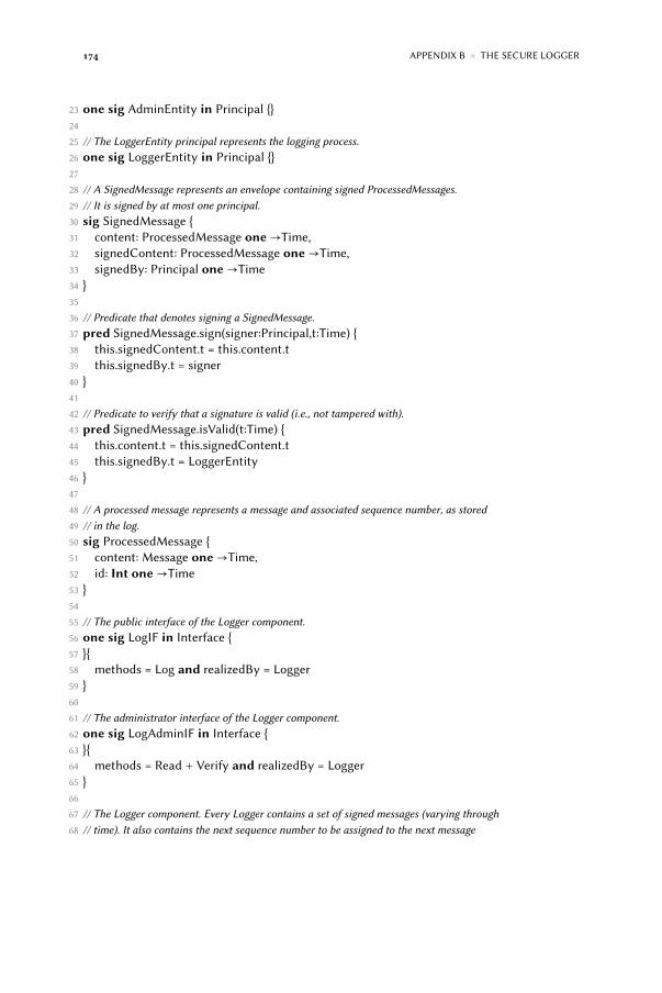
174 APPENDIX B ◾ THE SECURE LOGGER
23 one sig AdminEntity in Principal {}24
25 // The LoggerEntity principal represents the logging process.26 one sig LoggerEntity in Principal {}27
28 // A SignedMessage represents an envelope containing signed ProcessedMessages.29 // It is signed by at most one principal.30 sig SignedMessage {31 content: ProcessedMessage one→Time,32 signedContent: ProcessedMessage one→Time,33 signedBy: Principal one→Time34 }35
36 // Predicate that denotes signing a SignedMessage.37 pred SignedMessage.sign(signer:Principal,t:Time) {38 this.signedContent.t = this.content.t39 this.signedBy.t = signer40 }41
42 // Predicate to verify that a signature is valid (i.e., not tampered with).43 pred SignedMessage.isValid(t:Time) {44 this.content.t = this.signedContent.t45 this.signedBy.t = LoggerEntity46 }47
48 // A processed message represents a message and associated sequence number, as stored49 // in the log.50 sig ProcessedMessage {51 content: Message one→Time,52 id: Int one→Time53 }54
55 // The public interface of the Logger component.56 one sig LogIF in Interface {57 }{58 methods = Log and realizedBy = Logger59 }60
61 // The administrator interface of the Logger component.62 one sig LogAdminIF in Interface {63 }{64 methods = Read + Verify and realizedBy = Logger65 }66
67 // The Logger component. Every Logger contains a set of signed messages (varying through68 // time). It also contains the next sequence number to be assigned to the next message

B.1 THE REFINED SECURE LOGGER MODEL 175
69 // to be logged, as state.70 sig Logger in Component {71 contains: set SignedMessage→Time,72 nextUID: Int one→Time73 }{74 all t:Time,c:Component,m:Message,i:Int {75 Execute[c,this,Log,m,t]⇒ some t1:Time | this.log[m,t,t1]76 Execute[c,this,Read,m+ i,t]⇒ this.read[m,i,t]77 Execute[c,this,Verify,i,t]⇒ this.verify[i,t]78 }79 }80
81 // A helper function to calculate the nextUID−attribute of a logger at a certain point82 // in time. This allows multiple messages to be written to the log per time tick (as83 // opposed to simply incrementing the nextUID by one, which would make logging sequential).84 fun calculateNextUID[l:Logger, t:Time] : one Int {85 {nb:Int { all c:Component {86 (t = TO/first)⇒ (nb = #{m:Message | Execute[c,l,Log,m,t]}) else87 nb = (l.nextUID.(t.prev)).add[#{m:Message | Execute[c,l,Log,m,t]}]88 }89 }90 }91 }92
93 // The write−predicate represents the implementation of the log−operation. Given a message,94 // it constructs a new ProcessedMessage, signs it, and stores it in the log as an atomic95 // operation.96 pred Logger.log(m:Message, t:Time, t1:Time) {97 some pm:ProcessedMessage, s:SignedMessage {98 pm.content.t = m99 0 < = pm.id.t100 pm.id.t < calculateNextUID[this,t]101 s.content.t = pm102 s.sign[LoggerEntity,t]103 s in this.contains.t104 }105 t = t1106 }107
108 // Reification of the Log operation.109 one sig Log in Operation {}110
111 // The checkForEntry−predicate represents the implementation of the read−operation. It112 // checks whether a principal p can read a signedMessage s at time t in the log.113 pred Logger.read(m:Message, res:Int, t:Time) {114 ( this.verify[1,t] and some pm:ProcessedMessage |

176 APPENDIX B ◾ THE SECURE LOGGER
115 pm.content.t = m and116 pm.id.t ≥ 0 and pm.id.t < this.nextUID.t and117 some sm:this.contains.t | sm.content.t = pm118 ) implies res = 1 else res = 0119 }120
121 // Reification of the Read operation.122 one sig Read in Operation {}123
124 // The implementation of the verify operation. It checks whether the log is intact at125 // time t.126 pred Logger.verify(intact:Int, t:Time) {127 (this.allEntriesAccountedFor[t] and this.entriesAreValid[t])⇒128 intact = 1 else intact = 0129 }130
131 pred Logger.allEntriesAccountedFor(t:Time) {132 all i:this.nextUID.t.prevs | i ≥ 0 implies some s:this.contains.t | s.content.t.id.t = i133 }134
135 pred Logger.noExtraneousEntries(t:Time) {136 all s:this.contains.t | s.content.t.id.t < this.nextUID.t and s.content.t.id.t ≥ 0137 }138
139 pred Logger.entriesAreValid(t:Time) {140 all i:Int {141 0 ≤ i and i < this.nextUID.t implies142 one s:this.contains.t | s.content.t.id.t = i and s.isValid[t]143 }144 }145
146 // Reification of the verify operation.147 one sig Verify in Operation {}148
149 pred Logger.verify(callr:Component, intact:Int, t:Time) {150 Invoke[callr,this,Verify,intact,t]151 }152
153
154 // Assumptions.155 //////////////////////////////////////////////////////////////////156
157 // The integrity of the nextUID−attribute of every logger should be protected. I.e.,158 // it should conform to the calculateNextUID−specification at all times.159 pred AssumeTamperproofNextUID {160 all t:Time, l:Logger {

B.1 THE REFINED SECURE LOGGER MODEL 177
161 l.nextUID.t = calculateNextUID[l,t]162 }163 }164
165 // The signature−method used should be unforgeable. I.e., either the content remains166 // identical to the signed content, or the signer of the signature changed.167 pred LoggerSignaturesCannotBeForged {168 all s:SignedMessage, ts:Time {169 all t:ts.nexts {170 (s.signedContent.t = s.signedContent.ts and171 s.signedContent.t.content.t = s.signedContent.ts.content.ts and172 s.signedContent.t.id.t = s.signedContent.ts.id.ts) or173 s.signedBy.t ≠ s.signedBy.ts174 }175 }176 }177
178 // A logger does not overwrite valid entries with the same sequence number that are already stored.179 pred LoggerDoesNotOverwriteEntries {180 all s:SignedMessage,t:Time | s.isValid[t]⇒181 no s1:SignedMessage − s,t1:t.prevs |182 s1.isValid[t1] and s1.content.t1.id.t1 = s.content.t.id.t183 }184
185 // A logger only stores items that were written to it via the Log operation.186 pred OnlyStoreLoggedItems {187 all l:Logger,m:Message,t:Time | l.read[m,1,t] implies188 some c:Component,t1:t.prevs+ t | Execute[c,l,Log,m,t1]189 }190
191 // Connectors connecting loggers to shops are reliable, i.e., they remain connected.192 pred LogConnectorsAreReliable {193 all l:Logger,c:Component,conn:getConnectors[c,l] {194 conn.isReliable195 }196 }197
198 // Every connector used by a shop to connect to a logger has been correctly initialized,199 // i.e., the shop waits until the logger is properly connected before initializing200 // log−invocations.201 pred LogConnectorsCorrectlyInitialized {202 all c:Component,l:Logger,conn:getConnectors[c,l] {203 let t = {t:Time | #conn.buffer.t > 0 and no t1:t.prevs | #conn.buffer.t1 > 0}{204 c + l in conn.connects.t205 }206 }

178 APPENDIX B ◾ THE SECURE LOGGER
207 }208
209 // Authentic invocations of the Log−operation are routed only through connectors between210 // the caller and the logger associated to the caller.211 pred LogCallsCorrectlyRouted {212 all i:Invocation,t:Time,l:Logger |213 i.hasAuthenticCaller and i.of = Log and l in i.receivers implies214 all c:Connector | i in c.buffer.t⇒ c in getConnectors[i.caller,l]215 }216
217 // Connectors connecting loggers to shops are tamperproof, i.e., invocations buffered in218 // those connectors are unmodifyable.219 pred LogConnectorsAreTamperProof {220 all l:Logger,c:Component,conn:getConnectors[c,l] {221 conn.tamperProof222 }223 }224
225 // Context definition, which consists of a set of logger−specific and more general226 // architectural assumptions.227 // RG denotes residual goals, while E denotes an expectation.228 fact Context {229 AssumeTamperproofNextUID // RG230 LoggerSignaturesCannotBeForged // RG231 LoggerDoesNotOverwriteEntries // RG232 AtLeastOnceInvocationSemantics // E233 LogConnectorsAreReliable // E234 LogConnectorsCorrectlyInitialized // E235 LogCallsCorrectlyRouted // E236 LogConnectorsAreTamperProof // E237 }238
239
240 // Security requirement definitions.241 //////////////////////////////////////////////////////////////////242
243 // It should be impossible to delete messages logged by a shop−component244 // to the log undetectedly. Either logged messages can be read back on all245 // later times, or the log is no longer intact.246 pred NothingDeleted {247 all t:Time,m:Message,l:Logger,c:Component | Invoke[c,l,Log,m,t] implies (248 some t1:t.nexts+ t {249 all t2:t1.nexts+ t1 {250 l.verify[1,t2] implies l.read[m,1,t2]251 }252 }

B.2 THE FIRST ABSTRACTION—ABSTRACTLOGGER 179
253 )254 }255
256 assert Requirement { NothingDeleted }257
258 // An example visualization of model instances.259 pred Show {260 #Logger = 1261 some t:Time,callr:Component,l:Logger,m:Message | Invoke[callr,l,Log,m,t]262 some t:Time,l:Logger | l.nextUID.t = 1263 some t:Time,l:Logger | l.nextUID.t = 2264 all t:Time,l:Logger | l.verify[1,t]265 }266
267 run Show for 2268 check Requirement for 3
B.2 The first abstraction—AbstractLogger
1 module patterns/abstractlogger[Message,Time]2 open util/ordering[Time] as TO3 open metamodel[Time]4
5 one sig Log in Operation {}6
7 one sig Verify in Operation {}8
9 one sig Read in Operation {}10
11 one sig LogIF in Interface {12 }{13 methods = Log and realizedBy = Logger14 }15
16 one sig LogAdminIF in Interface {17 }{18 methods = Read + Verify and realizedBy = Logger19 }20
21 sig Logger in Component {22 contents: set Message→Time23 }{24 all t:Time,c:Component,m:Message,i:Int {25 Execute[c,this,Log,m,t]⇒ this.log[m,t]26 Execute[c,this,Read,m+ i,t]⇒ this.read[m,i,t]

180 APPENDIX B ◾ THE SECURE LOGGER
27 Execute[c,this,Verify,i,t]⇒ this.verify[i,t]28 }29 }30
31 pred Logger.log(m:Message,t:Time) {32 m in this.contents.t33 }34
35 pred Logger.read(m:Message,res:Int,t:Time) {36 (this.verify[1,t] and m in this.contents.t) implies res = 1 else res = 037 }38
39 pred Logger.verify(res:Int,t:Time) {40 (all m:Message, c:Component, t1:t.prevs+ t |41 (Execute[c,this,Log,m,t1] or m in this.contents.TO/first) implies42 m in this.contents.t) implies res = 1 else res = 043 }44
45 // Assumptions.46 //////////////////////////////////////////////////////////////////47
48 pred LogConnectorsAreReliable {49 all l:Logger,c:Component,conn:getConnectors[c,l] {50 conn.isReliable51 }52 }53
54 pred LogConnectorsCorrectlyInitialized {55 all c:Component,l:Logger,conn:getConnectors[c,l] {56 let t = {t:Time | #conn.buffer.t > 0 and no t1:t.prevs | #conn.buffer.t1 > 0}{57 c + l in conn.connects.t58 }59 }60 }61
62 pred LogCallsCorrectlyRouted {63 all i:Invocation,t:Time,l:Logger |64 i.hasAuthenticCaller and i.of = Log and l in i.receivers implies65 all c:Connector | i in c.buffer.t⇒ c in getConnectors[i.caller,l]66 }67
68 pred LogConnectorsAreTamperProof {69 all l:Logger,c:Component,conn:getConnectors[c,l] {70 conn.tamperProof71 }72 }

B.3 THE SECOND ABSTRACTION—STATELESSLOGGER 181
73
74 fact Context {75 AtLeastOnceInvocationSemantics76 LogConnectorsAreReliable77 LogConnectorsCorrectlyInitialized78 LogCallsCorrectlyRouted79 LogConnectorsAreTamperProof80 }81
82
83 // Security requirement definitions.84 //////////////////////////////////////////////////////////////////85
86 pred NothingDeleted {87 all t:Time,m:Message,l:Logger,c:Component | Invoke[c,l,Log,m,t] implies (88 some t1:t.nexts+ t {89 all t2:t1.nexts+ t1 {90 l.verify[1,t2] implies l.read[m,1,t2]91 }92 }93 )94 }95
96 assert Requirement { NothingDeleted }97
98 pred Show {99 #Logger = 1100 some t:Time,callr:Component,l:Logger,m:Message | Invoke[callr,l,Log,m,t]101 all t:Time,l:Logger | l.verify[1,t]102 }103
104 run Show for 2105 check Requirement for 3
B.3 The second abstraction—StatelessLogger
1 module patterns/statelesslogger[Message,Time]2 open util/ordering[Time] as TO3 open metamodel[Time]4
5 one sig Log in Operation {}6
7 one sig Verify in Operation {}8
9 one sig Read in Operation {}

182 APPENDIX B ◾ THE SECURE LOGGER
10
11 one sig LogIF in Interface {12 }{13 methods = Log and realizedBy = Logger14 }15
16 one sig LogAdminIF in Interface {17 }{18 methods = Read + Verify and realizedBy = Logger19 }20
21 sig Logger in Component {22 }{23 all t:Time,c:Component,m:Message,i:Int {24 Execute[c,this,Log,m,t]⇒ this.log[m,t]25 Execute[c,this,Read,m+ i,t]⇒ this.read[m,i,t]26 Execute[c,this,Verify,i,t]⇒ this.verify[i,t]27 }28 }29
30 pred Logger.log(m:Message,t:Time) {31 some c:Component,t1:t.prevs+ t | Execute[c,this,Log,m,t1]32 }33
34 pred Logger.read(m:Message,res:Int,t:Time) {35 (this.verify[1,t] and some t1:t.prevs+ t,c:Component |36 Execute[c,this,Log,m,t1]) implies res = 1 else res = 037 }38
39 pred Logger.verify(res:Int,t:Time) {40 res = 141 }42
43
44 // Assumptions.45 //////////////////////////////////////////////////////////////////46
47 pred LogConnectorsAreReliable {48 all l:Logger,c:Component,conn:getConnectors[c,l] {49 conn.isReliable50 }51 }52
53 pred LogConnectorsCorrectlyInitialized {54 all c:Component,l:Logger,conn:getConnectors[c,l] {55 let t = {t:Time | #conn.buffer.t > 0 and no t1:t.prevs | #conn.buffer.t1 > 0}{
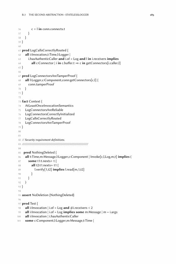
B.3 THE SECOND ABSTRACTION—STATELESSLOGGER 183
56 c + l in conn.connects.t57 }58 }59 }60
61 pred LogCallsCorrectlyRouted {62 all i:Invocation,t:Time,l:Logger |63 i.hasAuthenticCaller and i.of = Log and l in i.receivers implies64 all c:Connector | i in c.buffer.t⇒ c in getConnectors[i.caller,l]65 }66
67 pred LogConnectorsAreTamperProof {68 all l:Logger,c:Component,conn:getConnectors[c,l] {69 conn.tamperProof70 }71 }72
73 fact Context {74 AtLeastOnceInvocationSemantics75 LogConnectorsAreReliable76 LogConnectorsCorrectlyInitialized77 LogCallsCorrectlyRouted78 LogConnectorsAreTamperProof79 }80
81
82 // Security requirement definitions.83 //////////////////////////////////////////////////////////////////84
85 pred NothingDeleted {86 all t:Time,m:Message,l:Logger,c:Component | Invoke[c,l,Log,m,t] implies (87 some t1:t.nexts+ t {88 all t2:t1.nexts+ t1 {89 l.verify[1,t2] implies l.read[m,1,t2]90 }91 }92 )93 }94
95 assert NoDeletion {NothingDeleted}96
97 pred Test {98 all i:Invocation | i.of = Log and #i.receivers < 299 all i:Invocation | i.of = Log implies some m:Message | m = i.args100 all i:Invocation | i.hasAuthenticCaller101 some c:Component,l:Logger,m:Message,t:Time |

184 APPENDIX B ◾ THE SECURE LOGGER
102 Invoke[c,l,Log,m,t] and Execute[c,l,Log,m,t]103 all l:Logger,t:Time | l.verify[1,t]104 }105
106 run Test for 2107 check NoDeletion for 3

Bibliography
[ABL+10] D. Akhawe, A. Barth, P.E. Lam, J. Mitchell, and D. Song. Towards aformal foundation of web security. In Computer Security FoundationsSymposium (CSF), 2010 23rd IEEE, pages 290–304. IEEE, 2010.
[AJK+12] J. Andronick, R. Jeffery, G. Klein, R. Kolanski, M. Staples, H. Zhang,and L. Zhu. Large-scale formal verification in practice: A processperspective. In Proceedings of the 34th International Conference onSoftware Engineering (ICSE), pages 1002–1011. IEEE Press, 2012.
[AKL+12] Dalal Alrajeh, Jeff Kramer, Axel van Lamsweerde, Alessandra Russo,and Sebastián Uchitel. Generating obstacle conditions for requirementscompleteness. In Proceedings of the 34th International Conference onSoftware Engineering (ICSE), pages 705–715. IEEE Press, 2012.
[AL91] M. Abadi and L. Lamport. The existence of refinement mappings.Theoretical Computer Science, 82(2):253–284, 1991.
[AL95] M. Abadi and L. Lamport. Conjoining specifications. ACM Transactionson Programming Languages and Systems (TOPLAS), 17(3):507–535, 1995.
[Arr10] V. Arraj. ITIL®: The basics. Buckinghampshire, UK, 2010.
[BB05] B. Boehm and V.R. Basili. Software defect reduction top 10 list.Foundations of empirical software engineering: the legacy of Victor R.Basili, page 426, 2005.
[BCK03] Len Bass, Paul Clements, and Rick Kazman. Software Architecture inPractice, Second Edition. Addison-Wesley Professional, April 2003.
[BCL+06] E. Bruneton, T. Coupaye, M. Leclercq, V. Quéma, and J.B. Stefani. Thefractal component model and its support in Java. Software: Practice andExperience, 36(11-12):1257–1284, 2006.
[Bel06] S.M. Bellovin. On the brittleness of software and the infeasibility ofsecurity metrics. IEEE Security & Privacy, page 96, 2006.
185

186 BIBLIOGRAPHY
[Ber05] L. Bernstein. Trustworthy software systems. ACM SIGSOFT softwareengineering notes, 30(1):4, 2005.
[Bjo87] D. Bjorner. On the use of formal methods in software development. InProceedings of the 9th international conference on Software Engineering,pages 17–29. IEEE Computer Society Press, 1987.
[Boy93] C. Boyd. Security architectures using formal methods. IEEE Journal onSelected Areas in Communications, 11(5):694 –701, jun 1993.
[BPW03] M. Backes, B. Pfitzmann, and M. Waidner. A universally composablecryptographic library. Proceedings of the 10th ACM Conference onComputer and Communications Security, 2003.
[BS 95] BS 7799 – Information Technology, Code of practice for informationsecurity management and Information Security Management Systems,Specification with guidance for use, 1995.
[BZJ04] M.A. Babar, L. Zhu, and R. Jeffery. A framework for classifying andcomparing software architecture evaluation methods. In Proceedings ofthe Australian Software Engineering Conference (ASWEC), pages 309–318.IEEE, 2004.
[CC009] Common Criteria for information technology security evaluation, July2009. Version 3.1, revision 3.
[CCMS02] L. Campbell, B. Cheng, W. McUmber, and R. Stirewalt. Automaticallydetecting and visualising errors in uml diagrams. RequirementsEngineering, 7(4):264–287, 2002.
[CGJ+03] E. Clarke, O. Grumberg, S. Jha, Y. Lu, and H. Veith. Counterexample-guided abstraction refinement for symbolic model checking. Journal ofthe ACM (JACM), 50(5):752–794, 2003.
[CGKP06] C.L. Chen, P.S. Grisham, S. Khurshid, and D.E. Perry. Designand validation of a general security model with the Alloy Analyzer.Proceedings of the ACM SIGSOFT First Alloy Workshop, pages 38–47,2006.
[CGL94] E.M. Clarke, O. Grumberg, and D.E. Long. Model checking andabstraction. ACM Transactions on Programming Languages and Systems(TOPLAS), 16(5):1512–1542, 1994.
[CGR95] D. Craigen, S. Gerhart, and T. Ralston. Formal methods reality check:Industrial usage. Software Engineering, IEEE Transactions on, 21(2):90–98,1995.

BIBLIOGRAPHY 187
[CKCW03] B.H.C. Cheng, S. Konrad, L.A. Campbell, and R. Wassermann. Usingsecurity patterns to model and analyze security requirements. Int.Workshop on Requirements for High Assurance Systems (RHAS), 2003.
[CMP94] E. Chang, Z. Manna, and A. Pnueli. Compositional verification of real-time systems. In Logic in Computer Science, 1994. LICS’94. Proceedings.,Symposium on, pages 458–465. IEEE, 1994.
[Coo71] Stephen A. Cook. The complexity of theorem-proving procedures. InProceedings of the third annual ACM symposium on Theory of computing,STOC ’71, pages 151–158, New York, NY, USA, 1971. ACM.
[Cou] PCI Security Standards Council. PCI Data Security Standard. http://www.pcisecuritystandards.org.
[CS10] M.R. Clarkson and F.B. Schneider. Hyperproperties. Journal of ComputerSecurity, 18(6):1157–1210, 2010.
[CW96] E.M. Clarke and J.M. Wing. Formal methods: State of the art and futuredirections. ACM Computing Surveys (CSUR), 28(4):626–643, 1996.
[DCB09] B. Delaware, W.R. Cook, and D. Batory. Fitting the pieces together: amachine-checked model of safe composition. In Proceedings of the the7th joint meeting of the European software engineering conference and theACM SIGSOFT symposium on The foundations of software engineering,pages 243–252. ACM, 2009.
[DN02] L. Dobrica and E. Niemela. A survey on software architecture analysismethods. Software Engineering, IEEE Transactions on, 28(7):638 – 653,jul 2002.
[DRDJP11] Philippe De Ryck, Lieven Desmet, Wouter Joosen, and Frank Piessens.Automatic and precise client-side protection against csrf attacks. InLecture Notes in Computer Science, volume 6879, pages 100–116. Springer,September 2011.
[DWTB03] Y. Deng, J. Wang, J.J.P. Tsai, and K. Beznosov. An approach for modelingand analysis of security system architectures. IEEE Transactions onknowledge and data engineering, 2003.
[EHRLR80] L.D. Erman, F. Hayes-Roth, V.R. Lesser, and D.R. Reddy. The Hearsay-II speech-understanding system: Integrating knowledge to resolveuncertainty. ACM Computing Surveys (CSUR), 12(2):213–253, 1980.
[EKN+12] M.A. Esteve, J.P. Katoen, V.Y. Nguyen, B. Postma, and Y. Yushtein.Formal correctness, safety, dependability, and performance analysis

188 BIBLIOGRAPHY
of a satellite. In Proceedings of the 2012 International Conference onSoftware Engineering, pages 1022–1031. IEEE Press, 2012.
[ELC+98] S. Easterbrook, R. Lutz, R. Covington, J. Kelly, Y. Ampo, and D. Hamilton.Experiences using lightweight formal methods for requirementsmodeling. Software Engineering, IEEE Transactions on, 24(1):4–14, 1998.
[EMA+12] Jonas Eckhardt, Tobias Mühlbauer, Musab AlTurki, José Meseguer, andMartin Wirsing. Stable availability under denial of service attacksthrough formal patterns. In Fundamental Approaches to SoftwareEngineering, volume 7212 of Lecture Notes in Computer Science. SpringerBerlin Heidelberg, 2012.
[Epp12] Dana Epp. The evolution of elevation: Threat modeling ina Microsoft world. http://technet.microsoft.com/en-us/security/hh778966.aspx, January 2012.
[ETTM10] R. Evans, A. Tsohou, T. Tryfonas, and T. Morgan. Engineering securesystems with ISO 26702 and 27001. In System of Systems Engineering(SoSE), 2010 5th International Conference on, pages 1–6. IEEE, 2010.
[FF95] S. Fickas and M.S. Feather. Requirements monitoring in dynamicenvironments. Proceedings of the Second IEEE International Symposiumon Requirements Engineering, page 140, 1995.
[FKGS04] R.B. France, D.K. Kim, S. Ghosh, and E. Song. A UML-based patternspecification technique. IEEE Transactions on Software Engineering, 30(3),2004.
[GEM04] P. Grünbacher, A. Egyed, and N. Medvidovic. Reconciling softwarerequirements and architectures with intermediate models. Software andSystems Modeling, 3(3):235–253, 2004.
[GMMZ06] P. Giorgini, F. Massacci, J. Mylopoulos, and N. Zannone. Requirementsengineering for trust management: model, methodology, and reasoning.International Journal of Information Security, 5(4):257–274, 2006.
[GS02] Alexis Feringa Gary Stoneburner, Alice Goguen. Special Publication800-30: Risk management guide for Information Technology systems,2002.
[GVW03] M. Graff and K. VanWyk. Secure coding: principles and practices. O’ReillyMedia, Incorporated, 2003.
[Has04] B. Hashii. Lessons learned using alloy to formally specify MLS-PCAtrusted security architecture. In Proceedings of the 2004 ACM workshopon Formal methods in security engineering, pages 86–95. ACM, 2004.

BIBLIOGRAPHY 189
[HCS04] Spyros T. Halkidis, Alexander Chatzigeorgiou, and George Stephanides.A qualitative evaluation of security patterns. In International Conferenceon Information and Communications Security (ICICS), Malaga, Spain,October 2004.
[HD02] X. He and Y. Deng. A framework for developing and analyzing softwarearchitecture specifications in SAM. The Computer Journal, 45(1):111–128,2002.
[Hey12] Thomas Heyman. Formal pattern library, 2012. http://distrinet.cs.kuleuven.be/software/samodels/.
[HL06] Michael Howard and Steve Lipner. The Security Development Lifecycle:SDL: A Process for Developing Demonstrably More Secure Software.Microsoft Press, 2006.
[HLMN04] C. B. Haley, R. C. Laney, J. D. Moffett, and B. Nuseibeh. The effect of trustassumptions on the elaboration of security requirements. In 12th IEEEInternational Requirements Engineering Conference, 2004. Proceedings,pages 102–111, 2004.
[HLMN06] C.B. Haley, R.C. Laney, J.D. Moffett, and B. Nuseibeh. Using trustassumptions with security requirements. Requirements Engineering,11(2):138–151, 2006.
[HLMN08] C. B. Haley, R. C. Laney, J. D. Moffett, and B. Nuseibeh. Securityrequirements engineering: A framework for representation and analysis.IEEE Transactions on Software Engineering, 34(1):133–153, 2008.
[Hoa69] CAR Hoare. An axiomatic basis for computer programming.Communications of the ACM, 12(10):576–580, 1969.
[Hod97] W. Hodges. A shorter model theory. Cambridge University Press, 1997.
[Hog07] I. Hogganvik. A graphical approach to security risk analysis. PhD thesis,University of Oslo, Faculty of Mathematics and Natural Sciences, 2007.
[HSJ12] T. Heyman, R. Scandariato, andW. Joosen. Smarmy, a language to verifythe security of software architectures. Technical report, KU Leuven, 2012.(to appear).
[HYS+04] X. He, H. Yu, T. Shi, J. Ding, and Y. Deng. Formally analyzing softwarearchitectural specifications using SAM. The Journal of Systems &Software, 71(1-2):11–29, 2004.
[HYS+11] Thomas Heyman, Koen Yskout, Riccardo Scandariato, Holger Schmidt,and Yijun Yu. The security twin peaks. In International Symposium onEngineering Secure Software and Systems, February 2011.

190 BIBLIOGRAPHY
[ISO07] ISO 26702 – Systems engineering – Application and management of thesystems engineering process, 2007.
[ISO09] ISO 27000 – Information technology – Security techniques – Informa-tion security management systems – Overview and vocabulary, 2009.
[ISO11] ISO 42010 – Systems and software engineering —- Architecturedescription, 2011.
[Jac01] M. Jackson. Problem frames: analysing and structuring softwaredevelopment problems. Addison-Wesley, 2001.
[Jac02] D. Jackson. Alloy: a lightweight object modelling notation. ACMTransactions on Software Engineering and Methodology (TOSEM),11(2):290, 2002.
[Jac06] D. Jackson. Software Abstractions: logic, language and analysis. The MITPress, 2006.
[JCJÖ92] I. Jacobson, M. Christerson, P. Johnson, and G. Övergaard. Objectoriented Software Engeneering. A Use Case Driven Approach. Addison-Wesley, 1992.
[Joi04] Joint Standards Australia/Standards New Zealand Committee OB-007.Risk management, 2004.
[Jon83] C.B. Jones. Tentative steps toward a development method for interferingprograms. ACM Transactions on Programming Languages and Systems(TOPLAS), 5(4):596–619, 1983.
[JS11] J. Jürjens andH. Schmidt. UMLsec4UML2—Adopting UMLsec to SupportUML2. Technical report, TU Dortmund, 2011.
[JSP+11] Bart Jacobs, Jan Smans, Pieter Philippaerts, Frédéric Vogels, WillemPenninckx, and Frank Piessens. VeriFast: A Powerful, Sound, Predictable,Fast Verifier for C and Java. In NASA Formal Methods, pages 41–55, 2011.
[Jür02] J. Jürjens. UMLsec: Extending UML for secure systems development.UML – The Unified Modeling Language, pages 1–9, 2002.
[Jür05] J. Jürjens. Secure systems development with UML. Springer Verlag, 2005.
[KCC03] Sascha Konrad, Betty H.C. Cheng, and Laura A. Campbell. Usingsecurity patterns to model and analyze security requirements. In IEEEInternational Conference on Requirements Engineering (RE), MontereyBay, CA, USA, 2003.

BIBLIOGRAPHY 191
[KETEH06] Darrell M. Kienzle, Matthew C. Elder, David Tyree, and James Edwards-Hewitt. Security patterns repository, version 1.0, 2006.
[KG06] J.S. Kim and D. Garlan. Analyzing architectural styles with Alloy. InProceedings of the ISSTA 2006 workshop on Role of software architecturefor testing and analysis, pages 70–80. ACM, 2006.
[KH06] K.M. Khan and J. Han. Assessing security properties of softwarecomponents: A software engineer’s perspective. In Proceedings of the2006 Australian Software Engineering Conference (ASWEC), Apr, pages18–21, 2006.
[KKC00] R. Kazman, M. Klein, and P. Clements. ATAM: Method for architectureevaluation. Technical report, Carnegie Mellon Software EngineeringInstitute, August 2000.
[Koz97] KA Kozar. The technique of data flow diagramming. http://spot.colorado.edu/~kozar/DFDtechnique.html, 1997.
[Kru95] P. Kruchten. Architectural blueprints – the “4+ 1” view model ofsoftware architecture. IEEE Software, 12(6):42–50, 1995.
[KWF07] A. Kubo, H. Washizaki, and Y. Fukazawa. Extracting relations amongsecurity patterns. In International Workshop on Software Patterns andQuality (SPAQu), 2007.
[KZB+12] I. Kuz, L. Zhu, L. Bass, M. Staples, and X. Xu. An architectural approachfor cost effective trustworthy systems. In Proceedings of the Joint 10thWorking IEEE/IFIP Conference on Software Architecture & 6th EuropeanConference on Software Architecture, aug 2012.
[LBC10] A. Lin, M. Bond, and J. Clulow. Modeling partial attacks with Alloy. InSecurity Protocols, pages 20–33. Springer, 2010.
[LKA+95] D.C. Luckham, J.J. Kenney, L.M. Augustin, J. Vera, W. Mann, andD. Bryan. Specification and analysis of system architecture using Rapide.IEEE Transactions on Software Engineering, pages 336–355, 1995.
[Lon93] David E. Long. Model checking, abstraction, and compositionalverification. PhD thesis, Carnegie Mellon University, 7 1993.
[LW94] Barbara H. Liskov and Jeanette M. Wing. A behavioral notion ofsubtyping. ACM Transactions on Programming Languages and Systems,16:1811–1841, 1994.
[MC81] J. Misra and K.M. Chandy. Proofs of networks of processes. IEEETransactions on Software Engineering, SE-7(4):417–426, 1981.

192 BIBLIOGRAPHY
[MC01] W.E. McUmber and B.H.C. Cheng. A general framework for formalizingUML with formal languages. International Conference on SoftwareEngineering, 2001.
[McG04] G. McGraw. Software security. Security Privacy, IEEE, 2(2):80–83, 3-42004.
[Mea03] C. Meadows. Formal methods for cryptographic protocol analysis:Emerging issues and trends. IEEE Journal on Selected Areas inCommunications, 21(1):44–54, 2003.
[MF12] Marsha Chechik Michalis Famelis, Rick Salay. Partial models: Towardsmodeling and reasoning with uncertainty. In Proceedings of the 2012International Conference on Software Engineering. IEEE Press, 2012.
[MFMP07] D. Mellado, E. Fernández-Medina, and M. Piattini. A Common Criteriabased security requirements engineering process for the developmentof secure information systems. Computer standards & interfaces,29(2):244–253, 2007.
[MGPVT04] B.B. Madan, K. Goševa-Popstojanova, K. Vaidyanathan, and K.S. Trivedi.A method for modeling and quantifying the security attributes ofintrusion tolerant systems. Performance Evaluation, 56(1-4):167–186,2004.
[Mic] Microsoft. SDL helps build more secure software. http://www.microsoft.com/security/sdl/learn/measurable.aspx.
[Mic06] B.M. Michelson. Event-driven architecture overview. Patricia SeyboldGroup, 2, 2006.
[Mor08] S. Morimoto. A survey of formal verification for business processmodeling. Computational Science–ICCS 2008, pages 514–522, 2008.
[MQ94] M. Moriconi and X. Qian. Correctness and composition of softwarearchitectures. ACM SIGSOFT Software Engineering Notes, 19(5):164–174,1994.
[MQR95] M. Moriconi, X. Qian, and R.A. Riemenschneider. Correct architecturerefinement. IEEE Transactions on Software Engineering, 21(4):356–372,1995.
[MS08] P. Merle and J.B. Stefani. A formal specification of the Fractal componentmodel in Alloy. Technical report, Institut National de Recherche enInformatique et en Automatique (INRIA), November 2008.

BIBLIOGRAPHY 193
[MTWJ96] N. Medvidovic, R.N. Taylor, and E.J. Whitehead Jr. Formal modelingof software architectures at multiple levels of abstraction. ejw,714:824–2776, 1996.
[NS78] R.M. Needham andM.D. Schroeder. Using encryption for authenticationin large networks of computers. Communications of the ACM,21(12):993–999, 1978.
[Nus01] Bashar Nuseibeh. Weaving together requirements and architectures.Computer, 34(3):115–117, 2001.
[NWP02] Tobias Nipkow, Markus Wenzel, and Lawrence C. Paulson. Isabelle/HOL:a proof assistant for higher-order logic. Springer-Verlag, Berlin,Heidelberg, 2002.
[Obj10] Object Management Group. Unified Modeling Language, superstructure.http://www.omg.org/spec/UML/, May 2010.
[Par72] D.L. Parnas. On the criteria to be used in decomposing systems intomodules. Communications of the ACM, 15(12):1053–1058, 1972.
[PM04] B. Potter and G. McGraw. Software security testing. Security & Privacy,IEEE, 2(5):81–85, 2004.
[Ray03] A. Ray. Security check: a formal yet practical framework for securesoftware architecture. Proceedings of the 2003 workshop on new securityparadigms, 2003.
[RAYH09] A. Raza, H. Abbas, L. Yngstrom, and A. Hemani. Securitycharacterization for evaluation of software architectures using ATAM.In Information and Communication Technologies, 2009. ICICT ’09.International Conference on, pages 241 –246, aug 2009.
[RLvV06] R. Roeller, P. Lago, and H. van Vliet. Recovering architecturalassumptions. The Journal of Systems & Software, 79(4):552–573, 2006.
[Roe01] W.P. Roever. Concurrency verification: introduction to compositional andnoncompositional methods. Cambridge tracts in theoretical computerscience. Cambridge University Press, 2001.
[RW11] N. Rozanski and E. Woods. Software systems architecture: workingwith stakeholders using viewpoints and perspectives. Addison-WesleyProfessional, 2011.
[SB10] C. Sprenger and D. Basin. Developing security protocols byrefinement. In Proceedings of the 17th ACM conference on Computerand communications security, pages 361–374. ACM, 2010.

194 BIBLIOGRAPHY
[Sch99] A. Schedler. Conceptualizing accountability. The self-restraining state:Power and accountability in new democracies, pages 13–28, 1999.
[Sch02] P. Schnoebelen. The complexity of temporal logic model checking.Advances in Modal Logic, 4:393–436, 2002.
[Sch03] Markus Schumacher. A theoretical model for security patterns. InSecurity Engineering with Patterns, volume 2754 of Lecture Notes inComputer Science, chapter 8. Springer Berlin / Heidelberg, 2003.
[SFBH+06] Markus Schumacher, Eduardo Fernandez-Buglioni, Duane Hybertson,Frank Buschmann, and Peter Sommerlad. Security Patterns. Wiley, 2006.
[SFC12] Rick Salay, Michalis Famelis, and Marsha Chechik. Languageindependent refinement using partial modeling. In FASE, pages 224–239,2012.
[SGM02] C. Szyperski, D. Gruntz, and S. Murer. Component software: beyondobject-oriented programming. Addison-Wesley Professional, 2002.
[Sha98] N. Shankar. Lazy compositional verication. Compositionality: TheSignificant Difference, pages 541–564, 1998.
[SHS08] A. Sarmah, S.M. Hazarika, and S.K. Sinha. Security pattern lattice:A formal model to organize security patterns. In 19th InternationalWorkshop on Database and Expert Systems Application (DEXA ’08), 92008.
[SNL05] Christopher Steel, Ramesh Nagappan, and Ray Lai. Core SecurityPatterns: Best Practices and Strategies for J2EE, Web Services, and IdentityManagement. Prentice Hall, 2005.
[Spi89] J.M. Spivey. The Z notation. Prentice-Hall, 1989.
[SS75] J.H. Saltzer and M.D. Schroeder. The protection of information incomputer systems. Proceedings of the IEEE, 63(9):1278–1308, 1975.
[Sta85] E. Stark. A proof technique for rely/guarantee properties. In Foundationsof software technology and theoretical computer science, pages 369–391.Springer, 1985.
[SYHJ08] R. Scandariato, K. Yskout, T. Heyman, and W. Joosen. Architectingsoftware with security patterns. Technical report, KU Leuven, 2008.
[vDSJ12] M. van Dooren, E. Steegmans, and W. Joosen. An object-orientedframework for aspect-oriented languages. In Proceedings of the 11thannual international conference on Aspect-oriented Software Development,pages 215–226. ACM, 2012.

BIBLIOGRAPHY 195
[vL00] A. van Lamsweerde. Formal specification: a roadmap. Proceedings of theConference on The Future of Software Engineering, pages 147–159, 2000.
[vL09] Axel van Lamsweerde. Requirements Engineering: from system goals toUML models to software specifications. Wiley, March 2009.
[VWW02] M. Vetterling, G. Wimmel, and A. Wisspeintner. Secure systemsdevelopment based on the Common Criteria: the PalME project. ACMSIGSOFT Software Engineering Notes, 27(6):129–138, 2002.
[WHD99] J. Wang, X. He, and Y. Deng. Introducing software architecturespecification and analysis in SAM through an example. Informationand Software Technology, 1999.
[Wil01] D.Wile. Residual requirements and architectural residues. In Proceedingsof the 5th International Symposium on Requirements Engineering (RE’01),Toronto, Canada, pages 194–201, 2001.
[Wit11] J.Wittocx. Finite domain and symbolic inferencemethods for extensionsof first-order logic. AI Communications, 24(1):91–93, 2011.
[WLBF09] J.Woodcock, P.G. Larsen, J. Bicarregui, and J. Fitzgerald. Formalmethods:Practice and experience. ACM Computing Surveys (CSUR), 41(4):19, 2009.
[Yu97] E.S.K. Yu. Towards modelling and reasoning support for early-phase requirements engineering. In Requirements Engineering, 1997.,Proceedings of the Third IEEE International Symposium on, pages 226–235.IEEE, 1997.


List of publications
Papers at international scientific conferences,published in full in proceedings
2012 Reusable formal models for secure software architectures; Heyman T, ScandariatoR, JoosenW;Working IEEE/IFIP Conference on Software Architecture (WICSA)and the 6th European Conference on Software Architecture (ECSA).
2010 Security in context: analysis and refinement of software architectures; Heyman T,Scandariato R, Joosen W; Annual IEEE Computer Software and ApplicationsConference (COMPSAC).
2009 Risk-driven architectural decomposition; Heyman T, Scandariato R, Joosen W;International Conference on Availability, Security and Reliability (ARES).
Papers at international scientific workshops,published in full in proceedings
2011 The security twin peaks; Heyman T, Yskout K, Scandariato R, Schmidt H, Yu Y;International Symposium on Engineering Secure Software and Systems.
2010 CsFire: Transparent client-side mitigation of malicious cross-domain requests;De Ryck P, Desmet L, Heyman T, Piessens F, Joosen W; Engineering SecureSoftware and Systems (ESSoS).
2009 Browser protection against cross-site request forgery; MaesW, Heyman T, DesmetL, Joosen W; ACM workshop on Secure execution of untrusted code.
2008 Towards a quantitative assessment of security in software architectures; Yaut-siukhin A, Scandariato R, Heyman T, Massacci F, Joosen W; Nordic Workshopon Secure IT Systems (NordSec).
197

198 LIST OF PUBLICATIONS
2008 Using security patterns to combine security metrics; Heyman T, Scandariato R,Huygens C, JoosenW; International Workshop on Secure Software Engineering(SecSE).
2007 An analysis of the security patterns landscape; Heyman T, Yskout K, ScandariatoR, JoosenW;Third International Workshop on Software Engineering for SecureSystems (SESS).
2006 Improving intrusion detection through alert verification; Heyman T, De Win B,Huygens C, Joosen W; Workshop on Security in Information systems (WOSIS).
Meeting abstracts, presented at internationalscientific conferences and symposia
2008 Using model checkers to elicit security metrics; Heyman T, Yskout K, Huygens C,Joosen W; Workshop on Security Metrics, MetriCon 3.0.
2007 Developing secure applications with metrics in mind ; Heyman T, Huygens C,Joosen W; Workshop on Security Metrics, MetriCon 2.0.
2006 Software security patterns and risk; Heyman T, Huygens C; First Workshop onSecurity Metrics (MetriCon).
Internal reports
2012 Smarmy – A language to verify the security of software architectures; Heyman T,Scandariato R, Joosen W; Department of Computer Science, KU Leuven.
2010 Towards a reference framework for legal compliance: a detailed overview; WuytsK, Heyman T, Scandariato R, Huygens C, Joosen W; Department of ComputerScience, K.U.Leuven.
2008 Security patterns: 10 years later ; Yskout K, Heyman T, Scandariato R, Joosen W;Department of Computer Science, K.U.Leuven.
2008 Architecting software with security patterns; Scandariato R, Yskout K, HeymanT, Joosen W; Department of Computer Science, K.U.Leuven.
2006 A system of security patterns; Yskout K, Heyman T, Scandariato R, Joosen W;K.U.Leuven, Department of Computer Science.


Faculty of EngineeringDepartment of Computer ScienceiMinds-DistriNet Research GroupCelestijnenlaan 200A box 2402
B-3001 Heverlee, Belgium