
A flow-through reaction cell for in situ X-ray diffraction and absorption studies of heterogeneous...
9
electronic reprint Journal of Synchrotron Radiation ISSN 0909-0495 Editor: G. Ice A flow-through reaction cell for in situ X-ray diffraction and absorption studies of heterogeneous powder–liquid reactions and phase transformations Pilar Ferrer, Iv´ an da Silva, Juan Rubio-Zuazo, Bel´ en F. Alfonso, Camino Trobajo, Sergei Khainakov, Jose R. Garcia, Santiago Garcia-Granda and Germ´ an R. Castro J. Synchrotron Rad. (2012). 19, 93–100 Copyright c International Union of Crystallography Author(s) of this paper may load this reprint on their own web site or institutional repository provided that this cover page is retained. Republication of this article or its storage in electronic databases other than as specified above is not permitted without prior permission in writing from the IUCr. For further information see http://journals.iucr.org/services/authorrights.html Synchrotron radiation research is rapidly expanding with many new sources of radiation being created globally. Synchrotron radiation plays a leading role in pure science and in emerging technologies. The Journal of Synchrotron Radiation provides comprehensive coverage of the entire field of synchrotron radiation research including instrumentation, theory, computing and scientific applications in areas such as biology, nanoscience and materials science. Rapid publication ensures an up-to-date information resource for sci- entists and engineers in the field. Crystallography Journals Online is available from journals.iucr.org J. Synchrotron Rad. (2012). 19, 93–100 Pilar Ferrer et al. · A flow-through reaction cell
Transcript of A flow-through reaction cell for in situ X-ray diffraction and absorption studies of heterogeneous...
electronic reprintJournal of
SynchrotronRadiation
ISSN 0909-0495
Editor: G. Ice
A flow-through reaction cell for in situ X-ray diffraction andabsorption studies of heterogeneous powder–liquid reactionsand phase transformations
Pilar Ferrer, Ivan da Silva, Juan Rubio-Zuazo, Belen F. Alfonso, CaminoTrobajo, Sergei Khainakov, Jose R. Garcia, Santiago Garcia-Granda andGerman R. Castro
J. Synchrotron Rad. (2012). 19, 93–100
Copyright c© International Union of Crystallography
Author(s) of this paper may load this reprint on their own web site or institutional repository provided thatthis cover page is retained. Republication of this article or its storage in electronic databases other than asspecified above is not permitted without prior permission in writing from the IUCr.
For further information see http://journals.iucr.org/services/authorrights.html
Synchrotron radiation research is rapidly expanding with many new sources of radiationbeing created globally. Synchrotron radiation plays a leading role in pure science andin emerging technologies. The Journal of Synchrotron Radiation provides comprehensivecoverage of the entire field of synchrotron radiation research including instrumentation,theory, computing and scientific applications in areas such as biology, nanoscience andmaterials science. Rapid publication ensures an up-to-date information resource for sci-entists and engineers in the field.
Crystallography Journals Online is available from journals.iucr.org
J. Synchrotron Rad. (2012). 19, 93–100 Pilar Ferrer et al. · A flow-through reaction cell

research papers
J. Synchrotron Rad. (2012). 19, 93–100 doi:10.1107/S0909049511040374 93
Journal of
SynchrotronRadiation
ISSN 0909-0495
Received 9 July 2011
Accepted 30 September 2011
# 2012 International Union of Crystallography
Printed in Singapore – all rights reserved
A flow-through reaction cell for in situ X-raydiffraction and absorption studies of heterogeneouspowder–liquid reactions and phase transformations
Pilar Ferrer,a,b* Ivan da Silva,a,b Juan Rubio-Zuazo,a,b Belen F. Alfonso,c
Camino Trobajo,c Sergei Khainakov,c Jose R. Garcia,c Santiago Garcia-Grandac and
German R. Castroa,b
aSpLine Spanish CRG Beamline at the ESRF, European Synchrotron Radiation Facility, BP 220,
38043 Grenoble, France, bInstituto de Ciencia de Materiales de Madrid-ICMM/CSIC, Cantoblanco,
Madrid 28049, Spain, and cDepartamentos de Fısica, Quımica Fısica y Analıtica y Quımica
Organica e Inorganica, Universidad de Oviedo, Oviedo, Spain. E-mail: [email protected]
A portable powder–liquid high-corrosion-resistant reaction cell has been
designed to follow in situ reactions by X-ray powder diffraction (XRD) and
X-ray absorption spectroscopy (XAS) techniques. The cell has been conceived
to be mounted on the experimental stations for diffraction and absorption of the
Spanish CRG SpLine-BM25 beamline at the European Synchrotron Radiation
Facility. Powder reactants and/or products are kept at a fixed position in a
vertical geometry in the X-ray pathway by a porous membrane, under forced
liquid reflux circulation. Owing to the short pathway of the X-ray beam through
the cell, XRD and XAS measurements can be carried out in transmission
configuration/mode. In the case of the diffraction technique, data can be
collected with either a point detector or a two-dimensional CCD detector,
depending on specific experimental requirements in terms of space or time
resolution. Crystallization processes, heterogeneous catalytic processes and
several varieties of experiments can be followed by these techniques with this
cell. Two experiments were carried out to demonstrate the cell feasibility: the
phase transformations of layered titanium phosphates in boiling aqueous
solutions of phosphoric acid, and the reaction of copper carbonate and l-
isoleucine amino acid powders in boiling aqueous solution. In this last case the
shrinking of the solid reactants and the formation of Cu(isoleucine)2 is observed.
The crystallization processes and several phase transitions have been observed
during the experiments, as well as an unexpected reaction pathway.
Keywords: powder–liquid reaction cell; cell design; in situ reaction; X-ray absorptionspectroscopy; X-ray diffraction; layered titanium phosphates.
1. Introduction
Many important high-technology production processes take
place on heterogeneous reactions systems. A very important
aspect in order to improve many real scale industrial processes
is a detailed understanding of the kinetics of the underlying
heterogeneous reactions, including the morphological
changes. The development of novel reaction process
mechanisms is currently a very challenging process, as there
is a significant lack of detailed understanding. Therefore, the
main goals of today’s research should be the tailored design of
reaction processes and their end products, based on a funda-
mental understanding of the underlying reactions paths and
intermediate products during heterogeneous reactions. To
obtain these goals, an important aspect is the use of adequate
techniques and experimental set-ups capable of producing
detailed information during the reaction process. X-ray
powder diffraction (XRD) and X-ray absorption spectroscopy
(XAS) are two techniques that are very well placed to fulfil
these requirements. X-ray powder diffraction is a rapid
analytical technique, primarily used for phase identification of
crystalline compounds by their diffraction pattern, and can
provide information on unit-cell dimensions and average bulk
composition. X-ray absorption spectroscopy is a useful tech-
nique particularly suitable for the study of the structural
features of nanosystems, such as powder materials, amorphous
and diluted systems. The strength of this spectroscopic tech-
nique is the capability to obtain the local electronic and
geometrical structure of a system, without the necessity of
presenting a long-range order. X-ray powder diffraction and
electronic reprint

X-ray absorption spectroscopy are also powerful tools for
time-resolved in situ studies of phase transitions and reactions,
since the electronic and crystallographic structure, including
its morphology, can be obtained. However, even for these two
suitable techniques, a special challenge is the case of powder–
liquid reactions where, normally, the reaction bath is perma-
nently in circulation and therefore the solid parts, either for
reactants or products, are in permanent movement. In this
contribution a novel reaction cell for in situ study of
temperature-controlled powder–liquid heterogeneous reac-
tions is presented, which has the main advantage that the solid
part is kept in the X-ray path in a fixed position. The cell has
been designed to be mounted at the X-ray absorption spec-
troscopy stations and the six-circle multipurpose diffract-
ometer of SpLine, the Spanish CRG BM25 beamline at the
ESRF. In the latter case the set-up takes advantage of the two-
dimensional CCD detector mounted on the beamline. A
typical full powder diffractogram can be recorded in a minimal
time of 200 ms, which defines the minimal kinetic timescale.
Many reactions require the presence of solvents to make
possible or catalyze the solid phase transformation. Several
varieties of cells have been developed to solve the needs that
the heterogeneous reaction measurements require (Villain et
al., 1993; Norby & Hanson, 1998; Alison et al., 2003; Grun-
waldt et al., 2005; FitzGerald et al., 2007; Wall et al., 2011). The
main innovations for the cell presented in this work are: the
fact that it can handle solid–liquid heterogeneous reactions
keeping the powder reactants and/or products in the beam
pathway in a fixed position during the chemical reaction,
forced liquid solvent circulation through the powder assuring
total powder–liquid contact, accurate temperature control in
the range between 293 and 493 K, and perfect compatibly with
XRD and XAS experiments.
In order to show the cell capability, two heterogeneous
solid–liquid reactions examples are presented. On one hand,
the heterogeneous reaction of layered titanium phosphates in
boiling aqueous solutions of phosphoric acid is studied by the
X-ray powder diffraction technique. Different molar concen-
trations of phosphoric acid allow the transformations between
the �, �, � and amorphous titanium phosphates phases. On the
other hand, the Cu–isoleucine complex synthesis has been
followed by X-ray powder diffraction and X-ray absorption
spectroscopy. The phase transformation of copper carbonate
and l-isoleucine amino acid in boiling aqueous solution has
been studied in situ and the complete reaction pathway of the
Cu(isoleucine)2 complex has been obtained.
2. Beamline set-up
X-ray measurements (diffraction and absorption) have been
carried out at the Spanish CRG SpLine-BM25 beamline at
the European Synchrotron Radiation Facility (ESRF), in
Grenoble, France. The beamline can tune the photon energy
in the range 5–35 keV (wavelength 2.48–0.35 A) with an
energy resolution of �E/E = 10�4. Owing to the high flux
(�1011 photons s�1) of the beamline and the two-dimensional
CCD detector, time-resolved experiments are possible. High-
resolution experiments are performed with a point detector
which is mounted on the diffractometer arm. A �–2� set-up,
together with a goniometer head, is installed in the detector
arm in order to use a crystal analyzer for polarization analysis.
The two-dimensional CCD detector is placed on a decoupled
motorized stage. The CCD detector (Photonic Science CCD)
is used to reduce the data acquisition time. The two-dimen-
sional detector allows a short acquisition time for a whole
powder diffraction pattern, showing the lack/presence of
preferred orientation and/or large grain size. The two-
dimensional detector is a very high resolution large-area X-ray
CCD array system that incorporates three tapered X-ray CCD
modules. The camera produces a 250 mm� 125 mm 33 Mpixel
resolution image with 32.8 mm pixel size and a final resolution
of 7651 � 3825 pixels. The three sensors are multiplexed
in order to deliver a seamlessly stitched image at the user
interface in 1.1 s with the option of further processing such
as auto-flatfield and offset correction, exploiting the CCD
interline structure (electronic shutter) of the Kodak KAI
11000 CCD. The accumulated charges are transferred to a
non-sensitive area in microseconds, allowing new exposure
while charges are transferred to the readout register. Simul-
taneous integration/readout enables 100% duty-cycle acqui-
sition and increases the acquisition rate. The acquisition time
can be varied as a function of binning and post-proceeding
between a few milliseconds and 30 min. In order to calibrate
the wavelength and the sample-to-detector distance, a silicon
standard powder is used, which is placed at the sample/cell
position on the diffractometer. The powdered-sample–
detector distance can be varied from a few centimetres up to
1500 mm. This distance defines the area detector resolution.
The CCD area detector can be rotated and placed with the
larger sides either vertically or horizontally in order to maxi-
mize the accepted solid angle along or perpendicular to the
synchrotron polarization plane. The use of a beam stopper is
required to avoid detector damage occasioned by the direct
X-ray beam hitting the CCD detector.
The cell has been conceived to be mounted on the SpLine-
BM25 six-circle multipurpose diffractometer at the ESRF
(Castro, 1998), taking advantage of the exceptional experi-
mental set-up. The station, which is situated at branch B of the
beamline, allows a great variety of techniques and experiments
to be performed, with several available sample environments,
as is the case of the powder–liquid reaction cell. The designed
reaction cell has also been conceived to be mounted on the
XAS station (Huber tower) located at branch A of the
beamline, permitting X-ray absorption experiments to be
carried out.
3. Solid–liquid reaction cell description
The strength of the system is the tight integration of every
component in the final design. The powder–liquid cell has
been engineered to provide stable and precise performance on
XAS and XRD measurements. The main body of the cell is
built of Teflon material, which provides a high corrosion
resistance, allowing a huge number of chemical reactions
research papers
94 Pilar Ferrer et al. � A flow-through reaction cell J. Synchrotron Rad. (2012). 19, 93–100
electronic reprint
owing to the great variety of solvents
that could be used. Moreover, the main
body can be built on different materials,
avoiding the limitations of the Teflon.
The outside dimensions of the body are
125 mm length � 30 mm width and
51 mm height. The cell body is covered
with stainless steel to offer physical
resistance and it is used also as a metal
heat protection. The cell dimension at
the powder block support (X-ray
pathway) is reduced to 4.5 mm.
The novel cell has been designed
taking into account that: (i) the powder
must be kept in the X-ray impact posi-
tion during the whole reaction process,
and (ii) it has to be a short X-ray
pathway, as the measurements are made
in transmission mode. The powdered
solid reactant is mounted in a special
set-up which keeps the solid powder
in the X-ray path during the chemical
reaction. The liquid cavity has been
designed to force the liquid circulation
through the powder, as the vapour
pressure in the cell increases, guaran-
teeing an optimum liquid–solid contact
at the wished working conditions. The
liquid circulates across the cell channel
under reflux conditions. The X-ray
pathway through the cell is minimized in
order to reduce the X-ray absorption by the reaction bath
formed by the liquid solvents and the solid powder (reactants
and/or products). Two Kapton/Teflon windows of 5 mm
aperture diameter are foreseen for the incoming and
outcoming X-ray beam. The outcoming solid-angle aperture
has been chosen to maximize the diffracted angular accepta-
tion, covering a maximal angular range of �45�. The chosen
angular acceptance allows a maximal d-space resolution of
0.3 A for a wavelength of 0.6 A (at the beamline photon
critical energy of 20 keV). The d-space resolution can be
adapted to the experimental requirements, changing either the
detector–cell distance or the photon beam wavelength. The
liquid temperature (and, consequently, the reaction tempera-
ture) is controlled between room temperature and 493 K
by four cartridge heaters and a temperature thermocouple
located in the cell body. The reaction temperature is limited by
the material of the main body, i.e. for this reaction, Teflon. The
cartridge heaters and the thermocouple are not in contact
with the reaction bath. The liquid temperature is measured
using a thermometer immersed in the reaction vessel. The cell
is formed of three main parts (see Figs. 1 and 2): the powder
holder, the body which contains the liquid channel (with the
corresponding openings for distillation column, thermometer
and the powder holder), and the protection/furnace cover.
The powder holder is a Teflon block, which has a reception
opening where the powder is positioned, covered by a porous
membrane envelope. The powder holder block is located
in the middle of the Teflon body. Hence, the powder is kept
in the beam position by the porous membrane, whose porous
size is lower than the grain size of the powder but high enough
to assure the liquid circulation. The powder holder has
additional openings to facilitate the liquid flow and,
depending on the membrane’s porous dimensions (available,
for example, from Goodfellow), powder from 500 nm to
50 mm grain size can be studied with an optimum contact with
the flow solution.
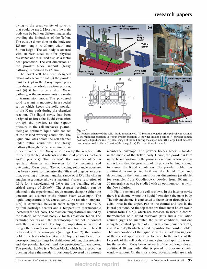
In Fig. 1 a scheme of the cell is shown. In the interior cavity
there is a channel where the liquid flows along the main body.
The solvent channel is connected to the exterior through seven
exits: three in the upper, two in the central and two in the
lateral positions. At the top there are three main holes: two in
conical form (14/23), which are foreseen to locate a control
thermometer or a liquid reservoir (left) and a distillation
column (right) to guarantee the reflux conditions, and one
elongated central aperture of 21 mm� 3 mm (length� width)
and 32 mm depth which is used to position the powder holder.
The incorporation of the liquid solvents is made through one
of the conical apertures of the top side. In the middle of the
long side of the cell body, a 12 mm cylindrical aperture is used
for the incident X-ray beam. At each of the cell long sides an
additional 20 mm outlet disc is placed to allocate a metal
window support. On the short sides, two extra holes are made
research papers
J. Synchrotron Rad. (2012). 19, 93–100 Pilar Ferrer et al. � A flow-through reaction cell 95
Figure 1(a) General scheme of the solid–liquid reaction cell. (b) Section along the principal solvent channel:1, thermometer position; 2, reflux system position; 3, powder holder position; 4, powder sampleposition; 5, liquid channel. (c) Real image of the cell during the experiment (the large CCD detectorcan be observed in the left part of the image). (d) Cross section of the cell.
electronic reprint
for construction reasons and they are used to facilitate the cell
cleaning after each experiment.
The two conical holes at the body top are used to insert a
thermometer, for checking the temperature of the bath, and a
reflux system, to continually cool down the vapour and return
it back to the cell as a liquid. Other devices can be mounted in
these holes, such as a dripping system, for example. The
aperture in the middle is used to introduce the powder holder
block in the liquid and it is covered with a Teflon plate, sealed
by a Teflon gasket. The powder-mounting aperture is very
narrow, in comparison with the body cell, reaching up to
4.5 mm width (see Fig. 1d). The powder holder system is fixed
with two Kapton/Teflon windows, which prevent the liquid
from getting out of the cell, also sealed by a gasket. The X-ray
outward window is maximized to cover a maximal angular
range of �45�. Finally, the lateral holes allow the exit of the
liquid when the chemical reaction has finished. They are
blocked by Teflon windows, linked with special extendable
gaskets, in case the main cell is deformed owing to the
temperature rising up in the interior.
Additional channels are present in the cell to carry out the
reaction at a controlled and homogeneous temperature, which
are not in contact with the solvent; there are four holes
coupled to the cell body and sited in the upper position, in
which four cartridge heaters are located to heat the cell body,
and also the liquid, in a homogeneous mode. In the lateral
view, two channels are available for placing two temperature
probes in order to control the temperature of the reaction.
The temperature of the bath reaction can be regulated
between room temperature and 493 K. As mentioned above,
the heater resistances are in direct contact with the Teflon
material and the bath is heated by thermal conductivity; so,
although the melting point of the Teflon is about 615 K, the
recommended bath temperature should be lower than 493 K
to avoid deformation of the main body. However, other
materials such as stainless steel, with a higher melting point
than Teflon, could be used to build the main body of the cell,
as in the cases of studying a reaction that takes place above
493 K.
Once the cell is mounted, the powder sample has to be fixed
and located in a particular place. A special powder holder has
been designed to assure that the sample is kept in a fixed
position, while the experiment is running, and the liquid
bathes and goes through it. This powder holder is also built of
Teflon material.
The entire cell is supported on a stainless steel platform in
order to avoid the possibility that the solvent sheds onto the
diffractometer tower. The cell can be moved into the X-ray
beam in a very precise and reproducible way, as the diffract-
ometer tower allows translations along the X, Y and Z axes,
besides other movements (rotation cradles). The X-ray
patterns are recorded as a function of either time or any other
parameter, such as temperature, if required.
3.1. Powder holder set-up
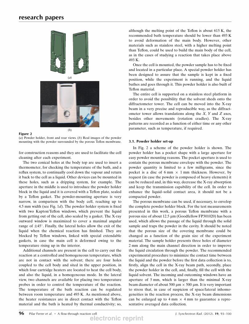
In Fig. 2 a scheme of the powder holder is shown. The
powder holder has a pocket shape with a large aperture for
easy powder mounting reasons. The pocket aperture is used to
contain the porous membrane envelope with the powder. The
powder quantity is limited to a few milligrams, since the
pocket is a disc of 6 mm � 1 mm thickness. However, by
request (in case the powder is composed of heavy elements) it
can be reduced and, in this way, decrease the X-ray absorption
and keep the transmission capability of the cell. In order to
enhance the liquid–solid contact area, it should not be a
compacted powder.
The porous membrane can be used, if necessary, to envelop
the complete powder holder block. For the test measurements
presented in this work, a porous Teflon membrane with a
porous size of about 12.5 mm (Goodfellow FP301020) has been
used, which allows the passage of the liquid through the solid
sample and traps the powder in the cavity. It should be noted
that the porous size of the covering membrane could be
changed as a function of the grain size of the experiment
material. The sample holder presents three holes of diameter
2 mm along the main channel direction in order to improve
the liquid circulation through the powder. The recommended
experimental procedure to minimize the contact time between
the liquid and the powder before the first data collection is to,
firstly, align the cell in the X-ray beam path, secondly, place
the powder holder in the cell, and, finally, fill the cell with the
liquid solvent. The incoming and outcoming windows have an
aperture of 5 mm, which is larger than the minimal X-ray
beam diameter of about 500 mm� 500 mm. It is very important
to stress that, in case of suspicion of space/lateral inhomo-
geneities in the reaction process, the X-ray beam dimensions
can be enlarged up to 4 mm � 4 mm to guarantee a repre-
sentative averaged data collection.
research papers
96 Pilar Ferrer et al. � A flow-through reaction cell J. Synchrotron Rad. (2012). 19, 93–100
Figure 2(a) Powder holder, front and rear views. (b) Real images of the powdermounting with the powder surrounded by the porous Teflon membrane.
electronic reprint

4. X-ray measurements
Diffraction experiments have been carried out at BM25B,
where the measurements were performed in transmission
mode with a monochromatic X-ray beam, set to an energy of
14.89 keV (wavelength 0.833 A) and with a spot size of 500 mm� 500 mm. The complete reaction pathways have been
followed by X-ray diffraction using a bidimensional CCD
camera. The reaction temperature ranges were varied from
room temperature to 453 K and to 373 K for the titanium
phosphates transformations and for Cu(ISO)2 formation,
respectively.
The resulting images were integrated using the XOP2.3
program (Sanchez del Rıo, 2009). The CCD detector was
mounted off-center to record the weak Debye–Scherrer
diffraction rings, reaching up to 0.54 A of d-space resolution at
the edge of the detector. The CCD detector produced images
with 3825� 1912 pixels, as 2� 2 binning was used. Diffraction
data were taken at 30 s of exposure time to obtain a better
signal-to-noise ratio for weak intensity reflections. The chosen
conditions (� = 0.833 A) allow a maximum reachable 2� angleof about 50� when the sample–CCD-detector distance is
197 mm. The diffraction data were obtained in transmission
mode, being the geometry of the cell designed to collect the
data with both detectors. The layered titanium phosphates
transformations and the crystallization of the Cu(ISO)2complex were studied under the same experimental condi-
tions.
In the case of the Cu(ISO)2 complex, XAS measurements
have been performed in transmission mode by using two
identical gas-filled ionization chambers just before and after
the studied sample, in order to ensure the best linearity in
the measurement of the photon intensity. A third ionization
chamber is present in order to simultaneously measure a
reference sample. XAS measurements were performed at the
Cu K-edge. Data treatment was achieved using ATHENA
software. Multishell EXAFS fitting analyses were performed
by shell fits on k2-weighted Fourier-transformed spectra using
the Artemis software (Ravel & Newville, 2005).
4.1. Synthesis route of layered titanium phosphate
Layered titanium and zirconium phosphates have received
considerable attention in the last decades. This is connected
with their unique properties: high thermal and chemical
stability, resistance to oxidation, selectivity to certain ions and
molecules, etc, which allows the use of such materials as ion
exchangers and adsorbents, molecular sieves, catalysts, ion
and proton conductors, and also as convenient matrices for
chemical modification (Clearfield, 1996). Two main types (�-and �-phases) of layered titanium phosphates are well known,
containing two phosphorus atoms per atom of group IV
element. In recent years some previously unknown titanium
phosphates in the form of metastable phases have been
synthesized (Garcıa-Granda et al., 2010; Bortun et al., 1996; Li
&Whittingham, 1993). The synthesis and investigation of such
metastable materials is of great theoretical and practical
interest, because it broadens the knowledge of the formation
mechanism of layered compounds in general and opens new
possibilities for the preparation of novel materials with regu-
lated and valuable properties.
The evolution of �, �, � and amorphous layered titanium
phosphates in boiling aqueous solutions of phosphoric acid
has been studied to demonstrate the feasibility of the cell. In
Figs. 3(a) and 3(b) the powder diffraction patterns show the
evolution of the �-layered titanium phosphates when the solid
phase is in contact with phosphoric acid solution at 5 and 10 M
research papers
J. Synchrotron Rad. (2012). 19, 93–100 Pilar Ferrer et al. � A flow-through reaction cell 97
Figure 3Reaction evolution of �-layered titanium phosphates with (a) 5M and (b)10 M concentration of phosphoric acid solution. (c) Reaction evolutionof amorphous titanium phosphate with 5 M concentration of phosphoricacid solution. (*, #: intermediate phases; RT: room temperature.)
electronic reprint

concentration, respectively. The
sample is placed in the sample holder
and the cell is filled with phosphoric
acid solution at 5 M concentration.
The evolution of the �-layered tita-
nium phosphate reveals an unex-
pected pathway, as an intermediate
phase appears after 30 min at 353 K.
The reaction continues until a
mixture of �-Ti(PO4)(H2PO4) and
�-Ti(HPO4)2�H2O products appears.
The pathway reaction of �-layeredtitanium phosphate in contact with a
10 M concentration of phosphoric
acid solution is different than the
previously described one. In this
synthesis route just one product is
synthesized when the reaction is
considered finished. Thus, the
concentration degree of the phos-
phoric acid which is in contact with
the �-layered titanium phosphate
is a critical factor in the reaction
pathway. The studied reactions can
be described as follows,
�-TiðPO4ÞðH2PO4Þ�2H2Oþ 5MH3PO4 !�-TiðPO4ÞðH2PO4Þ þ �-TiðHPO4Þ2�H2O;
�-TiðPO4ÞðH2PO4Þ�2H2Oþ 10MH3PO4 !� 0-TiðPO4ÞðH2PO4Þ�nH2O ðn> 2Þ:
The formation of �-titanium phosphate is also achieved
starting with an amorphous titanium phosphate, as Fig. 3(c)
shows. In this case the reaction has been carried out across an
unknown pathway, and an intermediate phase was formed,
Amorphous TiPþ 5MH3PO4 ! �-TiðHPO4Þ2�H2O:
A detailed description of the synthesis route, as well as the
intermediate phases, will be the subject of a forthcoming
manuscript (Garcıa et al., 2012). The cell described in this
work allows the study of the synthesis route of a solid in
contact with a liquid. As it is shown, starting from amorphous-
and �-titanium phosphate, the formation of �-titanium phos-
phate can be monitored. An unknown intermediate phase has
been detected; this phase is formed in the first steps of all
processes and evolves in a different way as a function of the
precursor materials and reaction parameters.
4.2. Cu–isoleucine crystallization
Copper(II) complexes of amino acids are usually consid-
ered as good model systems to attain a better insight into the
characteristics of naturally occurring metalloproteins. Copper
is an essential metalloelement, needed for metabolic processes
in cells, and isoleucine is one of the principal structural units in
metalloproteins, acting in enzymatic or structural functions.
Many enzymes require copper in the active site to be
biochemically active, superoxide dismutase being one of the
most studied. The concentration of substrates, inhibitors, pH
and many other factors play a crucial role on the protein’s
action. In order to increase the knowledge of protein’s func-
tionality, a detailed understanding of the metal amino acid
bonding and bonding mechanics, for example at different pH
values, is crucial for understanding many protein functional-
ities.
The crystallization reaction of copper carbonate and l-
isoleucine amino acid in boiling aqueous solution has been
followed by X-ray powder diffraction techniques and X-ray
absorption spectroscopy. The cell performance has also been
proved by following the phase transformation of copper
carbonate and l-isoleucine amino acid in boiling aqueous
solution. The experiment was carried out with 0.4 mmol of
CuCO3 and 0.8 mmol of l-isoleucine (with 10% excess), which
were mixed in a hand mortar and allocated in the powder
holder. Once the solid mixture is allocated in the sample
holder, the cell is filled with water and the reaction begins. The
role of the water is to dissolve the initial reactants, and also to
enhance the mobility of the ions. The chemical reaction was
carried out and the formation of Cu(ISO)2 occurs. Owing to
the exothermic character of the reaction and the reduced
space of the sample holder, the dissolved isoleucine and Cu
ions react, obtaining the complex formation (see Fig. 4). As
the mobility of the reactants is difficult because of the
presence of the porous membrane, the volume at the powder
holder is oversaturated with the reaction products, producing
their precipitation, that remains in the same sample holder
position (i.e. the X-ray beam position) instead of flowing
across the cell. This configuration allows the chemical reaction
to be followed, as the initial solid and the final product remain
research papers
98 Pilar Ferrer et al. � A flow-through reaction cell J. Synchrotron Rad. (2012). 19, 93–100
Figure 4Left: XRD patterns showing the phase evolution with temperature of the chemical reaction betweenCuCO3 and l-isoleucine amino acid. Theoretical initial reactants and Cu(ISO)2 complex patterns areshown in the lowest part. [*: Cu(ISO)2 complex.] Right: CCD images at room temperature (RT) after1 min and at 373 K after 130 min of reaction (upper and lower images, respectively).
electronic reprint

in the X-ray impact position during the whole reaction
process.
The diffraction study shows an immediate reaction between
initial products, as the Cu(ISO)2 complex is observed since the
first spectrum was collected, after 1 min in contact with water
(peak at 2� ’ 4.3�). In Fig. 4 the evolution of the chemical
reaction as a function of time and temperature is shown.
The theoretical expected diffractogram for the reactants and
product are also presented in Fig. 4 for comparison. After
1 min, the presence of the Cu(ISO)2 product is observed
suggesting an instantaneous chemical reaction. After 130 min
under reflux, the initial reactant l-isoleucine is still detected
on the spectra, which coincides with the excess of product
added at the beginning. All of the CuCO3 reacted to achieve
Cu(ISO)2. On the CCD images of Fig. 4 (right), the observed
Debye–Scherrer rings are continuous and uniform, indicating
a lack of preferential orientation, as expected.
The same reaction has been followed by XAS with the aim
of showing the compatibility of the cell presented in this work.
In Fig. 5 the evolution from the initial reactants to the final
product is shown. Two regions show the change of the ligands
around the Cu ion: the shape of the absorption curve presents
a single peak at the beginning of the reaction, whereas a
double peak can be distinguished at the end, and, a decrease
on the intensity around 9060 eV. An EXAFS spectrum of the
Cu(ISO)2 final product is shown in Fig. 6. Data are recorded
after the reaction is completed, and the results are in good
agreement with those expected for the Cu(ISO)2 complex.
The separation between the different Cu species is, in this
particular reaction, very difficult, since the oxidation state of
Cu ions does not change appreciably between the different
compounds (reactant and products). Even more, the XAS
signal is an average of present species. However, the observed
changes in XANES spectra from the beginning demonstrate
that the reaction takes place immediately when water comes
into contact with the products.
5. Conclusions
A novel reaction cell has been designed to follow in situ
powder–liquid reactions. Powder is mounted and placed at the
X-ray beam position inside a high-corrosion-resistant cell
(Teflon material). The powder is kept in the beam position
with a porous membrane, while the liquid circulates across
its channels, assuring total contact with the sample. The
temperature of the liquid is controlled, covering the range
from room temperature up to 493 K.
The cell feasibility has been demonstrated with two
complementary experiments. The �-layered titanium phos-
phate evolves to different phases depending on the concen-
tration of phosphoric acid, which has been studied by X-ray
powder diffraction. Moreover, Cu–isoleucine complex crys-
tallization has been studied by X-ray powder diffraction
techniques and X-ray absorption spectroscopy. Crystallization
processes, reaction pathways and/or phase transformations
can be studied with the cell presented in this work.
We thank the SpLine staff for their assistance in using
the BM25B-SpLine beamline. The financial support of the
Consejo Superior de Investigaciones Cientıficas and Spanish
Ministerio de Ciencia e Innovacion (PI201060E013) is also
acknowledged.
References
Alison, H. G., Davey, R. J., Garside, J., Quayle, M. J., Tiddy, G. J. T.,Clarke, D. T. & Jones, G. R. (2003). Phys. Chem. Chem. Phys. 5,4998–5000.
Bortun, A. I., Bortun, L., Clearfield, A., Villa-Garcıa, M. A., Garcıa,J. R. & Rodrıguez, J. (1996). J. Mater. Res. 11, 2490–2498.
Castro, G. R. (1998). J. Synchrotron Rad. 5, 657–660.
research papers
J. Synchrotron Rad. (2012). 19, 93–100 Pilar Ferrer et al. � A flow-through reaction cell 99
Figure 5Cu K-edge XANES spectra showing the evolution of the chemicalreaction between CuCO3 and l-isoleucine amino acid with temperature.
Figure 6Cu K-edge XAS spectra of Cu(ISO)2 in solid solution. Inset: EXAFSsignal accounting for the first coordination shells (solid circles) and fit(open curve) for the Cu(ISO)2 complex.
electronic reprint

Clearfield, A. (1996). Comprehensive Supramolecular Chemistry,Vol. 7, Solid-State Supramolecular Chemistry: Two-and Three-Dimensional Inorganic Networks, edited by G. Alberti and T. Bein.New York: Pergamon.
FitzGerald, V., Drake, K. O., Jones, J. R., Smith, M. E., Honkimaki, V.,Buslaps, T., Kretzschmer, M. & Newport, R. J. (2007). J.Synchrotron Rad. 14, 492–499.
Garcıa, J. R., Alfonso, B. F., Trobajo, C., Khainakov, S. & Garcia-Granda, S. (2012). In preparation.
Garcıa-Granda, S., Khainakov, S. A., Espina, A., Garcıa, J. R., Castro,G. R., Rocha, J. & Mafra, L. (2010). Inorg. Chem. 49, 2630–2638.
Grunwaldt, J. D., Ramin, M., Rohr, M., Michailovski, A., Patzke,G. R. & Baiker, A. (2005). Rev. Sci. Instrum. 76, 054104.
Li, Y. J. & Whittingham, M. S. (1993). Solid State Ion. 63, 391–395.Norby, P. & Hanson, J. C. (1998). Catal. Today, 39, 301–309.Ravel, B. & Newville, M. (2005). J. Synchrotron Rad. 12, 537–541.Sanchez del Rıo, M. (2009). Synchrotron Data Analysis Using XOP,in Synchrotron Radiation in Mineralogy, Seminarios de la SociedadEspanola de Mineralogıa, edited by M., Suarez, E. Ayuso andE. M. Manchado, pp. 109–141. Salamanca: Sociedad Espanolade Mineralogıa. (http://www.ehu.es/sem/revista/seminarios_m.htm#Vol6).
Villain, F., Briois, V., Castro, I., Helary, C. & Verdaguer, M. (1993).Anal. Chem. 65, 2545–2548.
Wall, A. J., Heaney, P. J., Mathur, R., Post, J. E., Hanson, J. C. & Eng,P. J. (2011). J. Appl. Cryst. 44, 429–432.
research papers
100 Pilar Ferrer et al. � A flow-through reaction cell J. Synchrotron Rad. (2012). 19, 93–100
electronic reprint