
.A FIXED-POWT SIMD ARRAY PROCESSOR AND ITS ...
166
.A FIXED-POWT SIMD ARRAY PROCESSOR AND ITS APPLICATIONS TO VIDE0 COMPRESSION CODiNG Peij ian Y I!.W DEPARTE~~EN~ DE GENIE ELECTRIQUE ET DE GÉNIE INFORMATIQUE ECOLE POLYTECHNIQUE DE MONTRÉAL MOIRE PRÉSENTÉ EN VUE DE L'OBTENTION DU GRADE DE MA~TNE ÈS SCIENCES APPLIQUÉES 0 Peijian YUAN, 200 1 .
-
Upload
khangminh22 -
Category
Documents
-
view
2 -
download
0
Transcript of .A FIXED-POWT SIMD ARRAY PROCESSOR AND ITS ...

.A FIXED-POWT SIMD ARRAY PROCESSOR AND ITS APPLICATIONS TO
VIDE0 COMPRESSION CODiNG
Peij ian Y I!.W
D E P A R T E ~ ~ E N ~ DE GENIE ELECTRIQUE ET DE GÉNIE INFORMATIQUE
ECOLE POLYTECHNIQUE DE MONTRÉAL
MOIRE PRÉSENTÉ EN VUE DE L'OBTENTION
DU GRADE DE MA~TNE ÈS SCIENCES APPLIQUÉES
0 Peijian YUAN, 200 1 .

National Li brary 1*1 of Canada Bibliothèque nationale du Canada
Acquisitions and Acquisitions et Bibliographie Services services bibliographiques
395 WeUington Street 395. nm Wellington OttawaON KlAON4 OttawaON K l A W Canada &nada
The author has granted a non- exclusive licence allowing the Naîional Libraxy of Canada to reproduce, loan, distn'bute or sell copies of this thesis in microform, paper or electronic formats.
The author retains ownership of the copyright in this thesis. Neither the thesis nor substantial extracts fiom it may be printed or othervcrise reproduced without the author's permission.
L'auteur a accordé une licence non exclusive permettant à la Bibliothèque nationale du Canada de reproduire, prêter, distribuer ou vendre des copies de cette thèse sous la forme de microfiche/nlm, de reproduction sur papier ou sur format électronique.
L'auteur conserve la propriété du droit d'auteur qui protège cette thèse. Ni la thèse ni des extraits substantiels de celle-ci ne doivent être imprimés ou autrement reproduits sans son autorisation.

Cette these intitulée:
A FIXED-POINT SIblD ARR4Y PROCESSOR AND ITS APPLIC.4TIONS TO
VIDE0 COMPRESSION CODIKG
presentée par: Peii ian YUAN
en \.ue de t'obtention du diplôme de: Maîtrise es Sciences Appliquées
a eté dûment accepté par jury d*esamen constitué de:
M. SAWAN Moharnad, Ph-D., président
M. BOIS GUY Ph.D.? membre et directeur de recherche
M. SAVARlA Yvon Ph.D., membre et codirecteur de recherche
M. ABOULHAMID Mostapha Ph-D., membre

iii
Dedication
To my wife, Beisong
To my son. Max

Acknowledgements
It is my great pleasure to express sincere gratitude to these who have contributed to the
successful compIstion of this Lvcrk.
1 have rt deep feeling of indebtedness to rny supervisor. Dr. Guy Bois for his constant
confidence. support. encouragement. guidance and providing me financial support. His
suggestions and criticisms were appreciated. and more irnportantly. his invaluable
frïendship \vil1 never be forgotten.
1 m also thankful to my CO-supervisor Dr. Yvon Savaria for introducing the thesis topic
to me and providing me financial support to work in the PULSE research group.
I would like to express my appreciation to my colleagues Ivan Kralijic and Claude
Villeneuve for helping me ~vith using the PULSE simulation tools.
Many thanks to al1 my friends for helping to establish a convivial environment in which
to work and for providing needed mord support during the difficult stages of this work.
Finally, 1 would like to thank my wife, Beisong Liu, to whom 1 owe much for her
unending patience, encouragement and understanding, without which I could hardIy have

completed this work. Special thanks are to my Iovely son Max Yuan, for understanding
me for not giving him full attention during his growing years.

Résumé
Ceîte thèse traite de l'utiiisation de PULSE. un processeur à instruction unique et domies
multiples (SIbID) pour le Traitement et la Compression d'Images en format MPEG-2. De
nos jours. les équipements de confikences vidéo. de téléphonie vidéo. de stockage
d'images vidtio numérique. de télévision haute-définition (HDTV) et les systèmes de
té ICvision et de multémedia numériques utilisent ce genre de fonctionnalité. Le stockage
ou la transmission de données d'image numérique impliquent des bandes passantes et des
quantités de m6moire importantes.
L'objectif principal de cette thèse est d'étudier Iss systèmes de codage de compression
d'imapc. Elle traite notamment de la conception de systèmes de haute performance et elle
Ctudie les compromis entre ia prticision et la complexité afin de réaliser des systèmes
sf'ticaces.
1) Le mémoire propose un algorithme précis et efficace pour effectuer la détection du
mouvement dans un flot d'images. La méthode de recherche complète est rapide et
précise. Elle est cependant très coûteuse. Une méthode de recherche graduelle mais
complète permet de trouver le meilleur appariement avec un effort moyen réduit pour
des images simples.

2) Une architecture adaptée à I'algorithme proposé est analysée et sa réalisation est
dicrite. Nos résultats démontrent qu'une puce PULSE permet de réaliser des
systkmes de compression d'images efficaces et flexibles. qui exploitent un haut degré
de parallélisme. Combiné avec un processeur de traitement de signal
commercialement disponible. 1s C4O de la société Texas Instruments. on peut réaliser
efficacement des systèmes de compression d'images de haute performance. Une telle
architecture hétérogène est efficace et flexible.
5) Nous proposons aussi une méthode efficace pour le calcul de la transformée cosinus
(DCT ct IDCT) avec uns puce PULSE. Cette methode exploite une table de cosinus
chargée dans les mémoires internes de PULSE pour éviter des calculs qui exigent un
grand nombre d'opérations.
Des dC\doppsments additionnels permettraient d'optimiser encore plus les aigorit!unes
proposés afin d'accélérer la compression d'image avec PULSE.

... V l l l
Abstract
This thesis is concemed with appiying a Fixed-point SIMD A m y Processor PULSE to
Image Compression with the MPEG-2 Standard. Video compressor is widely used in
today's video conferences. videophone. digital video storage. Storage or transmission of
digital images requires large memories and transmission bandwiuth. This motivated
rcssarch on this topic.
The main objecti\.e of this tliesis is to study image compression coding systems. Several
aspects of design h r Iiigh-speed and high accuracy processing are considered. In order to
rcdize a simple and effscti~x image compression coding system. the follo~ving areas are
im-estigatcd.
1 ) A high-spced and high accuracy aigorithm for motion estimation is developed.
The Gradua1 Full search method (GFSM) algorithm reduces the time required to find
matches and no possible solution is neglected in the search area. AIthough the
program is slightly more complex than the Full Searching Method (FSM), it is three
times faster than FSM u-hen processing a simpie image.
2) Different system architectures for image compression coding are discussed and
designed.

The results obtained dunng the research conducted for this thesis will prove that a
PULSE chip can be used to construct flexible multi DSP systerns, to accelerate image
compression. Using PULSE chips nith a C30 DSP and a FPGA control unit, we can
construct a hardwadsof tuxe system for image compression. It will not only reduce
the cost of an image compression coding systerns. but aIso improve its flexibility.
3) A simple and effective method to calculate DCT or IDCT with cosine functions
using the PULSE chip is deveIoped.
-4 possible method to computs the cosine function uses exponential function.
Calculating cosine function is relati~pely expensive. Thus we propose using
precomputed tables stored in PULSE'S interna1 memory to accelerate cornputation of
DCT or IDCT.
Further de\-cloprnents could impro\-e the throughput of image compression on the
PULSE chip.

Table of Contents
.-. Dedication ...............~.~............~.....~......................................... I I I
..................................................................... Acknowledgemen ts iv
....................................................................................... Résumé vi
.a.
........................................ A bstract ... . viii
Table of Contents ...................................................................... .u
............................................................................ a u res SV List of Fi,
......................................................................... List of Tables xvi
........................................................................ List of Appendix svii
Chapter 1 Introduction ........................................................... i
Chapter 2 A Review of Image Cornpressing Algorithms and Their
............................................ Processor Architectures 5
2. I MPEG standard ........................ ... .....................................
Bac kground ...........................................................
...................................... A bnef overview of MPEG-2
.......................................................... Convolution
2.2 Motion estimation algorithm .................................................
2.2.1 FSM (hl1 search method) ...........................................

3.2.2 CDS (conjugate direction searching) .............................. 16
2.2.3 Three-step searching ................................................. 18
2.2.4 CSA (cross-search algorithm) ..................................... 20
2.3.5 GFSM (gradua1 full search method) .............................. 21
33 2.2.6 Cornparison of the different algorithms ............. .. ........... --
2.3 Processor architecture review .................................................. 23
2.3.1 Custom chip set for MPEG-2 coding ............................. 23
2.3.2 VLSI implementation for motion estimation ..................... 26
2.3.3 APC based image compression system .................... .... 27
2.4 SIMD architecture of the PULSE chip .................... ... .............. 29
2.4.1 Introduction ........................................................... 29
2.4.2 Chip architecture .................................................... 31
2.4.3 Processing eIement block diagram ................................ 33
......................................................... 2.4.4 Instruction set 35
2.4.5 PULSE V1 assembler ................................................ 37
2.4.6 PULSE applications ................................................ 38
Chapter 3 Implementing a Convolution on PULSE ....................... 40
3.1 The convolution algorithm versus PULSE architectural features ......... 40
3.2 Structure of the convolution sohare ........................................ 44
3.3 Summary .............................. ,... .................................. 46

xii
Chapter 4 Motion Estimation Algorithms and
Implementations .......................................................... 47
4.1 Motion estimation algorithm .................................................. 47
4 . 1.1 General description ................................................ 18
4.1.3 Data structure for motion estimation in PULSE ............... 49
4.2 Gradua! fkI1 search method and full search
algorithm ~ v i t h the PULSE chip ............................................... 52
4.2.1 Speed of GFSM and FSM algorithms in PULSE ................ 52
4.2.2 Motion estimation program for PULSE .......................... 53
Chapter 5 DCT & IDCT Algorithms and
......................................................... Implementations 60
5-1 DCT & IDCT algorithms ........................................................ 60
5.1. I DCT ................................................................... 60
.................................................................. 5.1.2 IDCT 63
5.2 Implementation of DCT & IDCT on PULSE ............................... 64
5.2.1 Data structure of DCT on PULSE ............................... 64
5.2.2 Requirements and performance for DCT and
IDCT on PULSE ..................................................... 67
Chapter 6 Image Processing with PULSE Chips and
a C40 Processor ......................................................... 68
6.1 System architecture composed of one PULSE chip

. . X l l l
Chapter
and a C40 ......................................................................... 69
Irnprovernent of the C40PULSE system ..................................... 73
7 Conclusions ................................................................. 77
Results ............................................................................ 77
Future work ................................................................... 78
References .................................................................................. 8 1

xiv
List of Fi, oures
Figure 1-1
Figure 1-2
Figure 1-3
Figure 1-4
Figure 1-5
Figure 1-6
Figure 1-7
Figure 1-8
Figure 1-9
Figure 1-10
Figure f - I l
Figure 1- 12
Figure 2-1
Figure 2-2
Figure 2-3
Figure 2 4
Figure 2-5
Figure 2-6
Figure 2-7
Figure 2-8
Figure 2-9.
MPEG systern layer block diagram
System layer pack and packet structure
Picture types
Essentid elements of coding system in MPEG standard
Motion compensation
Zigzag Scan
MPEG cording system data flow block diagram
PULSE chip VI logic syrnbol - subject to design review
PULSE chip version 1 architecture
.Architecture of PEs and communication chains
PULSE V 1 -3 .f 16-bit processor architecture
Pipeline structure instruction in four cycles of dock
Function partitioning in h4PEG-2 encoding
Chip sets feature of flexible pipeline architecture based on RiSC CPUs
EST256 architecture
Structure diagram for a video image compression systern
The curent and previous fiames in a search area (N=l6,n=8)
CDS method
Three steps rnethod
CSA method
Gradually searching

Figure 3-1
Figure 3-2
Figure 3-3
Figure 3-4
Figure 3-5
Figure 4- 1
Figure 4-3
Figure 4-3.
Figure 4-4.
Figure 4-5.
Figure 4-6
Figure 4-7
Figure 7-8
Figure 5- 1
Figure 5-2
Figure 6- 1
Figure 6-2.
Figure 6-3
Figure 6-4
Splitting of 1K 'c 1 K original image into four parts for processing on a
PULSE chip
Distributed data structure for pa rde l computation of a convolution
Original picture data and result picture data (boundary effect)
Instruction pipelining in a convolution
Overiapping of calculation with exportation of output results
Position & relation between blocks & search areas in frarneA & frameB
Data of blocks and data of search areas in current picture and previous
pictursmemA and memB
Data structure in PEs
FSM & GFSM program diagram and its instructions (one block)
Flou-chart of a basic match unit
Data of block search in independent memory space
Program t 1
Prograni t2
Cosine table and input data stores in PEs mernories
DCT program diagram and instructions
The C-IOPULSE system
Program flowchart for the C40PULSE system
A C40PULSE system implementation
The C40/4PULSE system

xvi
List of Tables
Table 2- 1 Cornparison of dit'fsrent algoriiluns . . . . . . . . . . . . . . . . . . . . -. . . . . . . . . . . - -. . . 23
Table 6-1 Corn parison searching results with di fferent algorithrns . . . . . . . . . . . . . 76

List of Appendix ........................................................................ 85
. Ippendir -4 PCLSE F'l Compet it ive analjsis ....................................... 85
AppendLr B PULSE I..'I technical fearures .......................................... 89
..................... .4 ppcndix C PC'LSE C'I logic qmbol-strbject to design rerielt 91
.eippendi .r D The conidution proLqam jlolr.chart and program .................... 92
. 4pper;Jix E Conr.olrïtiott progrnn . duta q f source image
anudataofresultimdge .............................................. 96
..I ppertdix F Pro<qarn of .4 forion estirnution ......................................... 101
.......... ................................. .-lppendi .Y G Restrlr of titoric~n êsrirnurion .. 123
. 4ppemii.r H DCT prngt-crnlfor P CiLLCE ........................................... 125
.-l ppcndi.~ / /DCTprogrutn for- PLILSE .............................................. 128
-4ppenJi-r J Cosine Table ............................................................... 131
-4ppendix A' DCT progratn in C- -. .................................................... 132
.4 ppei1di.r L /DCT program in C'+ A ................................................. 134
-4ppendi-Y .A f Cosine rable generation program in C+ + ............................... 139
p e t d i \ Data tramfer prograrns-for c4O arzd PCTLSE ............................ 130
Appertdix O PULSE i's Cornpetitors ................................................. 147

CHAPTER 1
INTRODUCTION
A General Presentation of the Problem
This thesis presents a Hardware Software Co-design with the PULSE(Paralle1 Ultra
Large Scale Engine) chip used for image processing. It reports o r research canied as part
of the PULSE project that led to the development of the PULSE chip. Nowadays, rnoving
image coding systems have a very promising application field: Videoconferencing,
Videophone, Digital Video Storage, High-Definition Television (HDTV), Digital
Television and Multimedia Systems. In moving image coding systems, data compression
is needed for eficient management of large amounts of information. For example, a
coior image with a resolution of 1000 by 1000 pixels (picture elements) occupies 3
megabytes of storage in an uncompressed form. Data compression is especially useful for
the transmission of such high data through transmission channels. For instance, bit-rate
ranges fiom 10 Mb/s for broadcast-quality video to more than 100 Mb/s for KDTV
signais.
In order to reduce the transmission rate, using prediction techniques based on motion
estimation. This scheme increases the compression ratio to 50-200: 1. Motion Estimation
is the rnost demanding part in the coding algorithm. For example, in an image coding
system in MPEG2 standard (Figure 2-3), the compuîational power required is
approximately 1.2 GOPS; and around 50% of this effort is devoted to motion estimation.

At the decoder, motion estimation is not necessary, therefore lower computational power
is required.
Main Objective and Methodology
The main objective of this thesis is to study image compression coding systems and some
popular algorithms used for that purpose. Several aspects of design for high-speed and
high accuracy processing are considered. In order to realize a simple and effective image
compression coding system, the PULSE chip is considered as a potential platform.
The PULSE chip is a new ultra-high performance SIND (Single Instruction Multiple
Data) architecture DSP (Digital Signal Processing) for high-end video and related
applications. It has one controller and four process elements with clock of 54MHZ and 4
ports, having an VO capability as high as 2 16 Mega words/sec. Its VO ports are designed
to allow foming linearly connected chains of chips. With this syaem architecture and
using PULSE assembly language, a real time image processing system can be
implemented.
1) A high-speed and high accuracy algorithm for motion estimation is developed.
The Gradua1 Full search method (GFSM) algonthm reduces the time required to find
matches and no possible solution is neglected in the search area. AIthough the

progam is slightly more complex than the Full Searching Method (FSM), it is three
tirnes faster than FSM when processing a simple image.
A simple and effective method to calculate DCT or IDCT with cosine fûnctions
using the PULSE chip is developed.
A possible method to compute the cosine funaien uses the exponential fùnction.
Calculating cosine hnction is relatively expensive. Thus we propose using pre-
compute tables, stored in PULSE'S interna1 mernories, to accelerate computation of
DCT or IDCT.
Further developments could improve the throughput of image compression on the
PULSE chip.
3) Different system architectures for image compression coding are discussed and
designed.
The results obtained during the research conducted for this thesis will prove that a
PULSE chip can be used to construct flexible multi DSP systems, and to accelerate image
compression. Using PULSE chips with a C40 DSP and a FPGA control unit, we can
constnict a hardware/software systern for image compression. It will not only reduce the
cost of image compression coding systems, but also improve their fiexibility.

Organization of the Thesis
Chapter 3 will introduce the MPEG2 standard, the PULSE chip, and review some
previous research work. 1 will also describe sorne proposed algorithms. Chapter 3
describes the implementation of the convolution algorithms on PULSE. Chapter 4, 5 and
6 are the main parts o f this thesis. Chapter 4 and 5 include the processing of motion
estimation and DCT algorithms using the PULSE chip. A hardware and software co-
design system using a C40 chip & PULSE chips is discussed in chapter 6. Chapter 7
summarizes Our conclusions.

CHAPTER 2
A REVIEW OF IMAGE COMPRESSING ALGORITHMS AND
THEIR PROCESSOR ARCHITECTURES
2.1 MPEG Standard
In todq-'s world. videoconferencing. videophone. digital vidco storage. high-definition
telex-ision (HDTV). digital tele\ision and multimedia systems are widespread. Storage or
transmission of thssr data requires Iarge memories and high bit-rate. Thercfore. data
compression has been a subject of intensive research and dwelopmsnt for the p s t few
years.
2.1.1 Background
MPEG is a video compression technoIogy formulated b y the Mo\.ing P ictures Experts
Group. a joint cornmittee of the International Standardization Organization (ISO). The
first MPEG standard. known as MPEG-1. \vas fonnalized b>. the MPEG cornmittee in
January 1992.
MPEG- 1 compression incorporates both audio and video. For NTSC video (United States
and Japan) MPEG-1 uses the Standard Image Format (SIF) of 352x240 at 30 frames per
second. Audio is 16-bit, stereo sampled at 44KHz. MPEG data rates are variable,

although MPEG-1 was designed to provide VHS video quality. and CD-ROM audio
quality at a combined dzta rate of 1.2 megabits per second.
By resolution and data rate. MPEG-1 is targeted primarily at the computer and games
markets. By contrast. MPEG-2. adopted in the spring of 1994. is a broadcast standard
speci-ing 720x480 pisels resolution. playback at 60 tlelds per second and data rates
ranging from two to 10 megabits per second. MPEG-2 is the core compression
technology for DVD. the liigh-density CD-ROM standard that many feir will replace
VHS tapes as the standard for consumer video.
MPEG-3 was dropped. and MPEG-3 is a v e q low-bit-rate codec targeting
~.ideoconferencing. Intemet. and other low-bandwidth applications.
2.1.2 A Brief O\.en-iew of MPEG-2
I ) b'hat is MPEG-2
MPEG-2 is an audio/vidso compression/decompression standard. The audioivideo inputs
are cornpressed by an encoder. and decompressed by a decoder for playback.
The MPEG-2 standard is actually composed of three standards fomulated by the Moving
Pichires Experts Group, a working group of the International Organization for
Standardization (ISO). ISO standard 13 8 1 8- 1 covers the MPEG-2 system Stream, ISO
standard 1 38 1 8-2 addresses MPEG-2 video, and ISO standard 13 8 1 8-3 describes MPEG-

2 audio. Work on MPEG-2 startsd back in 1988. and al1 three standards were finally
approved in November 1 994.
MPEG-2 \.ide0 resolution can range from 720~480 to 1280x720, with the latter targeting
high-de finition tekvision ( HDTV) applications (cable 1 5.1 ). The most cornmon
resolution is 720x480, roughly the resolution of a full-screen NTSC (Nationai Television
Standards Cornmittee) image This contrasts with MPEG-1's masimum resolution of
352x240. or quartsr-scrern TV. Whils MPEG-1 is limitsd to 30 frarnes per second.
MPEG-2 c m opcrate at 60 fieIds, the scan rats of NTSC television. enhancing suitability
for broadcast applications like HDTV. cable television. and broadcast satellite.
2) Video Compression Tschnology
Since h4PEG-2 includes both audio and t-ideo. al1 MPEG-2 codecs must address both
formats. The block diagrarn of an MPEG-2 encoder system is shown in Figure2-1.
Source corn prrssor / h.Iodulator j b
V idco Video Source corn pressor ,
Ancillary data t
)I
Figurez-1 The block diagram of MPEG-2 encoder system
This thesis is mainly focused on the implementation of the video cornpressor. MPEG
video is specifically used in compression of video sequences which are simpIy a series of

pictures taken at closely spaced intervals in time. Except for the special case of a scene
change. these pictures tend to be quite similar from one to the next. htuitively. a
compression system ought to be able to take advantage of this similarity.
The compression techniques (compression models) with MPEG take advantage of this
similarity or predictability frorn one picture to the next in a sequence. Compression
techniques that use information frorn other pictures in the séquence are usually cailed
interframe techniques.
When a scene change occurs. interfrarne compression does not work and the compression
mode! should be changed. In this case the compression mode1 should be structured to
take advantage of the similarity of a given region of a picture to imrnediately adjacent
area in the sarnr picture. Compression techniques that only use information from a single
picture are usually callsd intraframe techniques. Thsse t\vo compression techniques.
interfrarne and intraframe. are at the heart of the MPEG video compression aigorithm.
Each video sequence is divided into one or more groups of pictures. and each group of
pictures is composed of one or more pictures of three different types. 1. P. and B, as
illustrated in Figure 2-2. I-pictures (intra-coded pictures) are coded independently,
entirely without reference to other pictures. P and B-pictures are compressed by coding
the differences between the picture and reference I or P-pictures, thereby exploiting the
similarities from one picture to the next.

P-pictures (prediciive-coded pictures) obtain predictions from ternpordy preceding 1 or
P-pictures in the sequence. whereas B-pictures (bi-directionaliy predictive-coded
pictures) obtain predictions fiom the nearest preceding and / or upcoming 1 or P-pictures
in the sequence. Different regions o f B-pictures may use different predictions, and may
predict from preceding pictures. upcoming pictures. both. or neither. Similady. P-pictures
rnay also predict from preceding pictures or use no prediction. If no prediction is used,
that region cf the picture is coded by intrafiarne techniques.
In a closed group of pictures. P and B-pictures are predicted only from other pictures in
that group of pictures: in an open group of pictures. the prediction rnay be from pictures
outside of the group of pictures [MPG97].

MPEG display order b
Fonvard prediction of B-kames -> Backward predict ion of B-Eames - Foward prediction of P-fiames
Figure 2-2 Picture types
3) Video Encoder
Figure 2-3 is a diagram showing the essential elements of a video coding system for
MPEG -2 Standard. Temporal redundancy is reduced using the folIowing process.

DI !Terence Picturc
B u ffer DCT ( N e w picturc) - +
I
1 Prrdicted picturc
Buffer fullness
+ Ï-l Quantizer 1
I I , picturc mcmor! C
motion estimation (o ld picture) 1 encoded cocfficicnts I I
+ Entrop? 1 P E S packets C'ontrol data cncoder B il tti-r b
L 1
Figure 2-3 Essential elements of vide0 coding system in MPEG -2 standard
In the motion estimation section. an input vidso frame. called a new picture. is compared
~v i th a previouslj. transmitted picture held in the picture memory. Pixel blocks (an area of
16-piscl n ide and 16-pixel high) of the previous picture are exarnined to determine if a
close match can be found in the iiew picture. First. the new picture buffer is divided into
8x8 pissI blocks. each 8x8 pisel block is ssarched in the old picture area of 16x1 6 pixels.
The match algorithm of motion estimation is: [Eq.2.1]

Where M is the distortion value. A[i.j] and B[i,j] are the new and odd images' pixel
values respectively. If the value of M is less than a threshola value. then the vector
coordinate of this block is cdled a close match. When a close match is found, a motion
vector is produced describing the direction and distance the pixel block moved. A
predicted picture is generated by the combination of al1 the close matches as shown in
Figurez-4. Finally. thé new picture is compared with the predicied picture to produce a
di fference picture [hIPG97].
The blocks o f a new picture are searched The blocks of old picture predict the in on old picture new picture
Figure 2 3 hdotion compensation
The process of reducing spatial redundancy begin with a DCT (Discrete Cosine
Transform) on the difference picture o f an 8x8 pixel block. The firs: value in the DCT
matrix (top lefi corner) represents the DC value of the 64 pixels of the 8s8 block. The
other 63 values in the matrix represent the AC values of the DCT with higher horizontal

and vertical frequencies as one moves to the bottom right corner of the rnatrix. If there is
little detail in the picture. these higher frequency values become very small. The DCT
values are presented to a quantizer which. in an irreversible manner, c m "round-off' the
values. Quantization noise anses because coefficients are rounded-offs. I t is important
that the round off be done in a manner that maintains the highest possible picture quality.
When quantizing the coefficients, the perceptual importance of the various coefficients
c m be exploited by allocating the bits to the perceptually more important areas. The
quantizer coarseness is adaptive. and is coarsest (fewest bits) when the quantization
crrors are espected to be least noticeable. The DCT coefficients are transmitted in a
zigzag order as sho~vn in Figure 2-5. After rounding. the higher frequency coefficients
often have a zero-\Aue (See Chapter 5 The Algorithm of DCT and IDCT). This leads to
frequent occurrence of several zero-value coefficients in sequence.
Figure 2-5 Zigzag Scan

The quantizer output is presented to an entropy encoder, which increases the coding
efficiency. by assigning shorter codes to more frequently occumng code words. The
entropy encoder bit strearn is placed in a buffer at a variable input rate. but taken from the
buffer at a constant output rate. This is done to match the capacity o f the transmission
channel and to protect the decoder buffer from overfiow or underfiow. If the encoder
buffer is almost fùll. the quantizer is signaled to decrease the precision of coefficients to
reduce the instantaneous bit rate. I f the encoder buffer is almost empty. the quantizer is
allowed to increase the precision of coefficients. The output of the buffer is packetized as
a Stream of PES packets. [DIG94]
In order to use the motion compensated picture for next prediction, the encoder requires
the reconstruction of the picture contained in the transmitted bitstrem. The quantizer
output is presented to the inverse quantizer, then to the inverse DCT. IDCT output adds
the predicted picture. and then place the result in the picture rnemory [MPG97].
The data flow coding system in MPEG standard is shown in Figure 2-6.

I n p u t n e w p i c t u r e w
Figure 2-6
I m o t i o n e s t i m a t i o n I
m o t i o n c o m p e n s a t e d p r e d i c t o I
e w p i c t u r e - p r e d i c t e d p i c t u r e l D C T t
1
I I D C T I
m o t i o n v e c t o r s ( o u t p u t )
p i c t u r e m e m o r y ( o l d p i c t u r e )
e n c o d e d c o e f f i c i e n t s
.
-
I n e w p i c t u r e t o o l d p i c t u r e m e m o r y
A
--
-
-
Data tlow of coding system in MPEG standard
2.1.3 Convolution
Most motion pictures need some pre-processing filter. This pre-processing enhances as
perceived by human visual sense. Convolution is one of the popular a1gonth.m~ used. It
will be discussed in chapter 3.
2.2 Motion Estimation Algorithm
Several algorithms for motion estimation have been proposed. A number of popular
methods, as well as the one proposed in this thesis, are presented below.

2.2-1 FSM (full search method)
The search of a block frame A (current picture) starts at the upper-left corner of the area
of frarne B(previous picture). If the value of M in equation [Eq2.1] is less than the
threshold value (zero means exact match). stop searching and output motion vector.
Othenvise search from Ieft to right and from top to bottom through frarne B. The search
is stopped when the right bottom corner is reached or when M is smaller than a threshold
value. This search sequence is illustrated in figure 2-7. [MPG97]
(nxn) block in the current fiame A
search area in the previous frame B
(nxn)block under the search in the area of previous fiame B, shiîled by i j
Figure 2-7 The current and previous fiames in a search area (N=16,n=8)
2-2.2 CDS (conjugate direction searching)
The search progresses in the direction of the smaller distortion, until a minimum
distortion is found (sel figure 2-8)[MPG97]. Descriptions of the algorithms refer to
points to express the shift between the reference positions in the hvo compared images.
The algonthm is listed below:

M is the value in equation [Eq2.1]: threshold is a value selected by the designer according
the allo~ved error: the left, right, up and down mean the direction of next compared center
point from the current center point.
[A ]horizontal: compare center point;
if (M<threshold) then stop search and output vector:
slse compare lefi and right point;
if((right(3)<left(O)and(~ght>threshold)en let right be the new center point;
elsit'((right(3)>left(O)and(lefi>threshold))en let lefi be the new center point:
endif:
endif:
repcat [.4]horizontaI until boundary or minimum point is found in horizontal direction:
[Blverticai: compare center point (4)(produced by [A]horizontal):
if (M<t!xeshoId) then stop search and output vector:
eIse compare up and down point;
if((up(7)<do~vn(6)md(up(7)>threshold))then let up(7) be the new center point:
clsif((up( 7)>do~\n(6)and(do\m(6)>threshold))then let down be the new center p p p p p p p p p p p p p - - - - - - - - - - - - - - -
point;
repeat [B]vsrtical until boundary o r minimum point is found in vertical direction;
end:

Figure 2-8 CDS method
2.2.3 Three-step searching
The three-step searching method looks for motion displacements. As it progresses
through the steps. the search range is decreased. As shown in figure 2-9[MPG97]. The
algorithm is listed below:
The definition of M and threshold are the sarne as with the CDS method.
step( 1 ): compare center point:
i f(M<threshold)then stop search and output vector;
else compare four (a) point;
if ((minimum M(a)<threshold)then stop search and output vector;
else compare tw M(aa)points(in minimum (a) direction);
if (minimum M(aa)<threshold)then stop search and output vector;

else new center point = the position of minimum M((a) or (aa));
endi f:
endif:
repeat step( 1 ) three times:(minimum M(aa) be the center for b search),(minirnurn M(b) be
the center for c search).
end:
From figure 2-9. the ria point (minimum (M(a) or M(aa))) is as the new center point in
step(2) searching. Using a similar method. the b point (minimum (M(b) or M(bb))) is
used as the new center point in step(3) searching.
Figure 2-9 Three steps method

2.2.3 CSA (Cross-Search -4lgorithm)
This algorithm differs from other search methods in the final step. In reference to figure
2-10. the final searching can be either the (X) or (+) directions. This is dirtermined by
minimum point. If i t is in lefi up comer or right down corner. the nest searching point
wi l l choose (X) points. If it is in right up corner or lefi down corner. the next searching
point will choose (+) points [CR090].
-7 -6 -5 -4 -3-3 -1 O 1 2 3 4 5 6 7
Figure 2- 10 CSA meîhod

2.2-5 GFSM(Gradua1 Full Search Method)
The gradual full search algorithm is a new method proposed here. It begiiis at the center
point and gradually increases the searching range around this point. The method is
illustrated in figure 2-1 1. This method \vas developed for two reasons.
We analysed the fast algorithms and we found similar problems with most o f them. The
search direction is usually guided toward the minimum value of M (equation 1) by
comparing 4 points nt each step. Thus many points inside the search region are skipped.
In some cases. moving by one pixel may give very different results. The search direction
is controlled by the minimum M. \vhich may lead to incorrect dccisions. Fast algorithm
are faster than FSM. but the? may give incorrect resuits.
-41~0. ~ v h e n successive frames d o not change much. the last motion sector is a short
distance from the center.
The gradual full search method typically takes a short time to find the best match. and
yet no point is ignored in the search area. Although the algorithm is slightly complex than
FSM. it is much faster for most applications.
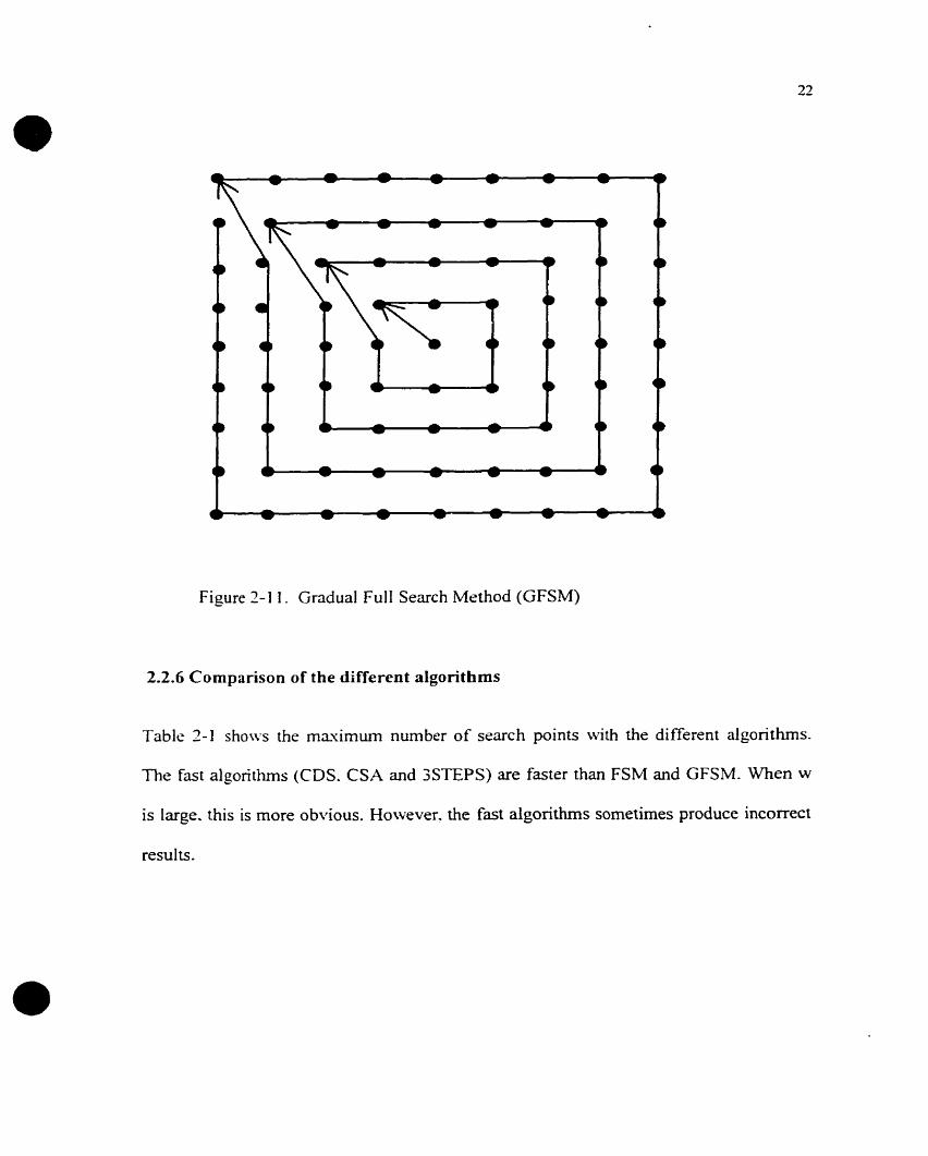
Figure 2- 1 1. Gndual Fu11 Search Method (GFSM)
2.2.6 Cornparison of the different algorithms
Table 2-1 shows the maximum number of search points with the different algonthms.
The fast algorithms (CDS. CSA and 3STEPS) are faster than FSM and GFSM. When w
is large. this is more obvious. However. the fast algorithms sometimes produce incorrect

W=(size of search area - size of block)/2
Table 2- 1 Cornparison of different algorithms
Algori thm
FSM
CDS
CSA
3 step
Gradua1 ly
2.3 Processor Architecture Review
Maximum number of search points
(2w+ 1 )?
3+2w
5+4 Iog w 7
25
(2 w+ 1 )'
w
In order to implement a MPEG coding system. a powerful calculation engine is required.
A huge number of calculations are required to perform motion estimation. DCT. etc.
Therefore. some special purpose chips are ofien used to implement these functions. Three
different MPEG-2 video encoders are discussed below.
2.3.1 Custom chip set for MPEG-2 coding
The paper "Two-chip MPEG-2 Video EncodingW[TW096], describes a system composed
of two chips that implements a MPEG-2 video encoder. The key features of these chips
set are:
! 6
IO89
35
21
---
1 089
4
81
I I
13
25
8 1
The Enc-M chip mainly executes motion estimation and compensation steps.
8
289
19
17
--
389

The Enc-C chip is the main coding and control chip. It esecutes not only coding
operations like discrete cosine transformation (DCT). inverse discrete cosine
transformation (IDCT). quantization (Q). inverse quantization (IQ). and
variablslen-eth coding (VLC). but also header generation, rate control. and output
buffer contro1. It has an external output buffer (FIFO-structured desired fiom a 2-
Mbit DRAM) to meet the requirements of the MPEG-2 algorithm.
R e o r d t g Field bu ffer
(4 Mbit w
And actikin; : detection ,
Motion estirnaor
(16 Mbit SDRAM or nvo 3 Mbit SDRAMs)
2: 1:-, ( 2 Mbit
1 - Data path
Figure 3- 12 Function partitioning in MPEG-2 encoding
Figure 2-12 shows the partitioning of the MPEG-2 encoder. It uses two encoder chips
(Enc-M and Enc-c). as well as three peripheral rnemories, a reordering field buffer. a
h e memory. and an output buffer.

Since MPEG-2 is a cornplex algorithm that requires a flexible and efficient control
structure. the pipeline architecture based on RISC CPUs (Figure 2-13) is used. Both the
Enc-M and Enc-C have thsir own RISC CPU. For flexible pipeline operation. each
îùnctiunal unit has a CPU VO device controllrd by the CPU via the VO port. Somc units
communicate with neighbouring units in a request-ûcknowledge manner.
- Video input
_I
Host CPU
Enc-C interface Host interface
RlSC CPU RISC CPU
With Multiply/
divide
Mot ion Estimation
in ter face FI FO
compensation + -+ DCT
OCTiQ ' DRAM
interface +
VLC - Figure 2- 13
CPUs
Chip set feature of flexible pipeline architecture based on RISC
The encoder chip set can easily be used to develop a compact encoder system. The
encoding algorithm is the MPEG-2 simple profile at main Ievel with a variable h e size
from 61 to 720 pixels (column) and 61 to 576 pixels (row). The chip set thus supports the
conventional sizes of 720x480. 720x576 and 640x380 pixels required for NTSC, PAL

and VGA standards. Using a 4 2 2 video input format. the maximum b e rate is 30
frames per second for a 720x480 f i m e size. That means the system processes up to
40.500 macroclocks( 16 by 16 pixel) every second for a maximum output of 1 5 Mbits per
second.
2.3.2 VLSI irnplementation for Motion Estimation
The papsr "VLSI Architecture for Motion Estimation using the Block-Matching
A1gcrrithm'-[VLS96] introducss the EST256 chip used for motion estimation. The
rtrcliitccture. EST256. ivhich consists of 256 processing elements. deals w<th a search
areri(32s32 piscl) for block( l6'i l6pisel) and perfoms I 1 GOPS at 33MHz clock
(subtrriction. absoluts \.alus determination. accumulation and companson). Considenng a
7 2 0 ~ 5 7 6 pixel image. the processing rate for motion estimation is 39 frames per second.
The numbsr of PEs n-orking concurrsntly is 256. and each single processor cornputes the
cost function for one of the 256 possible locations of the reference block within the
ssarch area. The rina? outputs the motion vector corresponding to each reference block.
256 cycles rifier the Iast pisel of the block has been entered into the array. Figure 2-14
shous the structure of the 256 processors array. To reduce the required bandwidth,
EST256 has three %bit input ports. After initial latency, the comparator block inputs one
error computation in each cycle and compares it +th the previous minimum, storing the
lowest. The boundary block disables the comparator when its input value is not valid, this
condition arises for some locations o f the blocks located on the top, bottom, lefi and right

boundaries of the image. The architecture provides the minimum error value, the
coordinates of the motion vector for this position and the error value for the (0,O) motion
vector (no movement).
Error(MV)
Figure 2- 14 EST256 architecture
- 1 1
Search , g U P P ~ ~ Lower 1 I
2.3.3 A PC based image compression system
M V 16, Y Error(O.0) I l - .
Re ference / - 0 . 0
'8 PE# 1 PE82 PEg3 +
The paper "A High-performance System for Real-time Video Image Compression
Applications"[HIG95] introduces a PC based image compression system. As shown in
Figure 2-15. the system consists of a PC-486, a motion estimation processor (MEP), a
DCTADCT processor (DCTADCTP), an image grabber, and a canera. MeanwhiIe, both
the MEP and DCTADCTP act as backend processors for PC-486 through its Vesa local-
bus interface. The PC-486 handles al1 the computations except motion estimation, DCT,
and Inverse DCT. Currently, by operating at 12.5MHz, the MEP takes around 1 OOus to
Error corn parator
PE#256
- - *
, A A
Control 1 1

cornpute the motion vector with tracking range 32x32 for each 16x16 block, and. the
DCTADCT takes around lOus to cornpute the two dimensional DCT or inverse DCT for
each 8x8 block. Also. overlapping data loading and processing c m achieve the optimal
performance. Therefore. for ench 256x256 image frame. the system presented ~vould take
around 25.6ms and lOms for computing motion vectors and two dimensional DCT or
inverse DCT individually.
Application Program
Image Compression
Control Program
Vesa
a Local Bus
.
a C
Quantization. Dequant izat ion, Run-Lm_& Coding Variable-Lm-& Coding
Estimation Processor
Image Grabber
Figure 2-1 5 Stmcture Diagram for a Video image compression System
Conclusions
As described above, in order to irnplement real time image processing, special processor
or Functional units are needed. As a general purpose DSP, single PULSE chip rnay not be
very powerful. However, it is easy to connect multiple PULSE chips to implement real

time image processing. An array of PULSE chips c m implement motion estimation.
DCT. etc. Each chip also implements a control unit. and these chips can easily be
interfaced with other processors. So- PULSE chips give us the ability to build different
systems to implsment various dgorithms and applications.
2.4 SIMD Architecture of PULSE Chip
2.4.1 Introduction
PULSE V1 is a 16 bit. fised point SIMD m a y processor designed to operate cit 53 MHz-
It contains (on a single chip) one controlltrr and four PEs (Processicg E l c ~ ~ n t s ) . The
custom designed architecture and instruction set of the PULSE processor allow efficient
impkmentation of al1 linear (muItiply add accumulate etc.). nonlinear (mnimum.
minimum. medium. r d order. etc.) and hybrid operations. thus pro\-iding a cornplete
solution for an' tïsed point DSP related applications.
PULSE V1 employs heavy parallsl operations to handle data 110. inter-processor
communications. address generations. and computations. One pgalle1 i n s ~ c t i o n could~ p p p p p p p p p p p p p p p - - - - - - - - - - - - -
sirnultaneously provide multiple computations (such as multiply add accumulate. and 3-
point rank order). multiple address generations and memory access. multiple data transfer
within the PE and between the neighbor PEs. Al1 these operations can be done at the rate
of one per cycle however. PULSE data-path is a 4-stage pipeline. One PULSE instruction
could perform more than IO conventionai operations. Effectively, the PULSE V1 chip
c m provide more than 2 Billion FUSC like operations per second for 1inea.r processing.

tlsually conditional sxecution on SIMD machines c m become highly inefficient, since
each PE might get diffsrent conditions. but the controller c m only supply a Single
Instruction based on a single condition. The usual way to sotve this multi-condition
problem is to turn somr PEs off. thus \vasting computation power. The imovative design
of the PULSE VI processor partly removes these conditional executions by supporting a
rich set of nonlinear instructions. For example. each PE cari implement a 3 point rank
order (maximum. medium, and minimum) in a single cycle of PULSE V1. The
implementation of this operation ( r d order of 4 LPectors. 3 data each) could require more
than 60 opsrations on conventional processors such as TI TMS320C40. In that specified
case. the PULSE processor provideç more than 4 Billion equivalent RISC like operations
per second for nonlinear processing.
To handle red-time image and \.ide0 processing. PULSE V I provides up to 864
Mb!tesisec. of bandxidth for data I/O and 332 Mbytss/sec. for inter-processor
communications. An imovative communication mechanism provides efficient use of the
bandw-idth and allows flexible algcrithrn mapping. Furthemore. the PULSE processor
provides a rich set of parallel and vector instructions. which can be used to improve the
application performance while reducing the program size.
PULSE VI provides easy system integration for different classes o f applications. It c m
be used as a stand-alone processor to replace some ASIC chips; it can be used as a co-
processor or accelerator to other processors of cornputer systems; it c m have extemai

programs and data memory for large kemel applications. The cascade o f multiple PULSE
chips is relatively straightfonvard. and it c m be done without any additional glue-logic.
-4 wide variety of architectures and related system applications c m be obtained wîth
suitably cascaded PULSE chips.
2-42 Chip Architecture
The PULSE chip version 1 is a PE array. nith four data communication ports (two of
them are compatible n-ith CAO). two address ports. global constant memory and intemal
program memorq.. The chip architecture is shonn in Figure 2-1 6. The PE array is the core
of the PULSE chip. Its architecture and communication chains are shown in Figure 2-1 7.

riddress port 1
modulo counter
Global constants ci C O N T R O L L E R pcm interna1 prograrn hlemory 2 5 6 x 1 6 memory 2 5 h x 16 I
north t [ From scan
To al1 blocks
and status reg isters 47T-'
1 ( cpu in terface
P U L S E V I I 1 -
I 1
C10 COXf port C-IO C o h l port Interface 8: fifo in ter face & fifo
R - Port I 1 x 'iI
[ port 3 1 1 port -I 1 I I I
I
Figure 2-1 6 PULSE Chip Version 1 Architecture

North Channel Port 1 r - -
b b s - Port3
I6bit - 16bit
South Channel
Figure 2- 1 7 .\rchitecture of PEs and Communication Chains
2.4.3 Proccssing element block diagram
Each of the four PULSE processing elements contains the following elements:
2 register files of 33. 16-bit words
- 1 read port. I w-rite port gives optimal storage density/access
* 2 mernories of 256, 16-bit words
- Single port 1 read/wite with direct link to communication charnels
- Addressing is direct, register indirect or via two modulo counters per memory
for read and write addresses

- Memories are designed to store data with a longer lifetime than those stored in
the register files
O 1 signsd multiplier-adder of 16s I6+32 bits tiith 32-bit signed result
- This is to implsmsnt MADD (multiply add)
- Direct connection of nsighbor processors data sources into addend input of the
multiplier-adder allows accumulation c h a h between processors to be built
O 1 accumulator of 32 bits
- Intcrnal rssolutiun is 33-bit signed u-ith overflow detection
- Programmable saturation and clipping functions to 32-bit signed or 31-bit
unsigned ranges
- Separate accumulator aIlows implementation of reduction algorithrns it is
possible to perfom MADD-4CC - multipIy-add-accumulate - 1 full barre1 shifier of 32 bits in. 32 bits out
- Supports full rangs of shift logical and arithmetic shifi operations - 1 multi-function 3-operand arithrnetic-logic unit
- Allows single c>.cle rank, mas. med. min, chip and cor functions on three
operands
- Usual arithmetic and logic functions available
The functional units o f each processing element are designed to operate in parallel so that
a typical PULSE instruction will simultaneously perform a computation, data load and
data communication operations. Also, the instruction set is designed to be as orthogonal

as possible so that any operation c m be performed on any piece of data, regardless of
where it resides. Figure 2- 1 8 presents PULSE V 1 -3 -f 1 6-bit processor architecture.
[accumulatorf 1 register 1 [ register 1 1 rnemory.4 1
I . source selection rnarrix : : I
1 destination selecrion marris 1
source I 1 I v I l
buses i
1 1 v . 1 1 1 1 * + + + + + + + *
destination v I I v I
buses v
r
Figure 2-1 8 PULSE V 1.3.f 16-bit procsssor architecture
2.4.4 Instruction Set
PULSE cmploys highly parallel operations to handle data W0. interprocessor
communications. address generations. and computations. Sorne parallel instmc~ions c m
sirnultaneously perform multiple computations. multiple address generations and rnemory
access. multiple data transfer \vithin the PE and between the neighbor PEs. Al1 its
operations c m be executed at the rate of one per cycle.
+ + t t t I 1
multiplier adder
PULSE instructions, due to a 4-stage pipeline. generally require four clock cycles, except
"stc", "fwd" and "io" instructions (one cycle). The pipeline operation is illustrated in
barre1 shi A e r
ALiJ

figure 2-1 9. At the first cycle. PULSE reads data fiom memory. register. or port. The
second and third cycles esecute the operation. The fourth cycle write the results back to
mernories. registers. or ports.
w rite
Instruction2 1 read \v rit4
Instruc (ion3 1 read write 1
Instruction4 read
Figure 2-1 9 Pipeline Structure Instruction in Four CycIes of- Clock
The PULSE instruction set is designed for both linear and non-linear digital signal
processing. with an ernphasis on imagdvideo processing. It provides a rich set of
instructions. including conventional instructions and estended non-conventional
instructions.
The instruction set is organized into the following functional groups:
PEs instruction set
MiscelIaneous
Data movement
Conventional arithmetic

Special arithrntltic
Conventional Iogical
Shiftlrotate
Transfer of control
Shi% registsr communication
Controller instxucrion set
ParaIlel instruction set
Vsctor instruction set
Each of rhsss groups is listed in the PULSE Technical Report Composite Document.
[PUL96]
2.4.5 PCJLSE V1 Assembler
The assembler translates assembly-laquage source files into object tiies. These files are
in common object file fomiat (COFF). Source files c m contain the following assembly
language elements:
Assembler directives
Assembly language instructions
The assembler does the following:
Process the source statements in a text file to produce an object file.
Produce a source listing (if requested) and provide the user with control over this
listing

Define and reference global syrnbols and append a cross-reference listing to the
source listing (if requested)
Each time the user uses the assembler. it processes one source program. The source
p r o g m is composed of one o r more fiies (The standard input is also a file.)
If no file namc is provided. the assembler attempts to read one input file from the
standard input. w-hich is normally the terminal.
2.4.6 PULSE Applications
As mentioned earlier. the PULSE proccssor supports both Iinear and non-linear
operations. and allows flexible algorithin mapping. These features make the PULSE
processor ideal for a \-en. wide range of applications. Some of them are listed below for
reference:
Filtering
Trans forrns
Imagelvideolgraphics procsssing
Image analysis and Machine Vision
Neural networks
Speech Processing
Communications
Instrumentation

A brief cornparison between PULSE V1 and other competitive devices from adaptive
solutions, Analog devices. Texas hstruments. and Oxford Computerç is provided in
appendix A. As can be seen from appendix A. PULSE vl offsrs significant advantages in
various aspects over the competitive devices. such as strong support for inter-processor
communication. and strong support for linear. non-linear and hybrid processing.
The PULSE V I technical features and the PULSE logic symbol are shown in appendix B
and appendix C.

CHAPTER 3
IMPLEMENTING A CONVOLUTION ON PULSE
3.1 The Convolution Algorithm Venus PULSE Architectural Features
The convolution algorithrn plays an important role in image processing. For instance. it is
used for noise reduction. edge sharpening and skeletonization. The generic convolution is
3daptt.d to perhnn these various functions by appropriately selecting the weights of its
kcrnel. In general. odd size ksrnels are used.
For esample. the 3 by 3 generic convolution a l g o r i t h is defined by equation [Eq.3.1].
Rr. j = C C Pr + i. + j Si. j
in this equation, is the convoluted pixel, value PV is the input image pi'ceI vaiue, and
SIJ is the convolution kemel weight. Equation 3.1 indicates that the 3 by 3 convolution
P'm.n (m by n pixel image) of each pixel Px.y requires knowledge of the values of its 8
immediate neighbors. On the image boundary, a different algorithrn is applied depending
on the application.

The following discussion of a convoIution applied to a 3 x 3 sarnple window on a 1K by
1 K image will refer to ri 2D FIR filter for brevity. These parameters are widely used for
preprocessing of images.
1 ) Each PE in a PULSE chip lias two 256 words memory units. For processing 1 K by 1K
images, they must be partitioned. One possibility is to split the images in vertical bands.
Thus we could calcuiate the 1024 lines of part one, then calculate part two, three and
four. as shown in Figure 3-1.
Figure 3- 1 Splitting of 1 K s i K original image into four parts for processing
on a PULSE chip
3) The processing of the convolution algorithm with a PULSE chip can be executed in
parallcl. because each chip has 4 PEs. The first data line (256 points) of part one is stored
in "memA". the second line is stored in "memB". Data is brought into 4PEs in parailel
through the "North Chamel"(Figure 2- 1 7). At the first instruction cycle, the data point
1.1 of the original image is stored in PEO, the unspecified data 'x' is stored in PEI, PE2
and PE3 individually. At the second instruction cycle, the point data 1.2 of the original
image and the data point 1.1 are respectively stored in PEO and PE 1, while an unspecified

data 'x' is stored in PE2 and PE3. This progresses until the pipeline is full and each
processor receives a pixel rit each cycle. The resuiting distributed data structure is shown
in figure 3-2. Respective positions in the rectangle correspond to data stored at the same
address o f respecti\-e processor mernories. The processing loop called "Ioopa" shown in
figure 3-5. thus cornputes 1 pisels of the output image in parallel.
O r i g i a a I I K i IK F.cruIt O D A T A R D 4 T 4
I I l 1 a l ? O 1.7 l t I 1u:4 l
2 . 1 : : : ! : 4 : 2 h :.- : a : 1h1:a
:: : ? : a : ' 2 , , : 7 : * : 1 " :a di Tl ;" R J L a t 1 . 4 r q d a 4 . 7 a s 4 . 9
l 1
- . - - - . - -- - - . - - - . - - - -- - -. A------.
P C ' L S E C I i I P
I P E I
Figure 3-2 Distributed data stmcture for parallel computation o f a convolution
3) Only t ~ v o lines of data can bc stored in rnernory, because each PE has only two 256
words memory units. The data in "memii" is first used while a third line o f data is stored
in "inemA". When the processing of first data line is finished, the third line has replaced
it in memory. The data in "memB" is then used and replaced by a fourth line of data.
Thus. '-memil'' always holds data of odd numbered lines, and "memB" stores even
nurnbered lines. Processing alternates from one to the other.

Line 1-3
Line 2-4
3 -5
MemA MernB MemA MernB Me mA MernB
Odd
Even
4) Con\.olution calculation results stored in csternai memop-. Considering the erosion of
image boundaries induced by the algorithm. the output image starts from the second line
at the second point (2.2). Thersfore. a result picture comprises 1022 b>. 1022 pixels and
edge points --B*' as shoun in Figure 3-2. The edge points "B" of result image can be filled
u-ith the cdgr points of the original image at the same position. In this case. the edge
points are not the result of a convolution. In order to overcome boundary effects between
parts (see Figure 3-1). the edge parts are calcuiated by processing 257 columns. Vertical
bands expansion is illustrated in figure 3-3. For part 1. columns 1 to 258 (original image)
are processed and columns 2 to 257 (result image) are produced. Part II. colurnns 257 to
514 (original image) are produced and coIurnns 258 to 513 (result image) are produced.
Part III, operates on pixels 512 to 770 (original image). and part IV operates on pixels
768 to 1074+2 (original image). Thus, only the edge of the 1 K by 1 K output picture
rshibits boundary effects. There are no boundary effects between part I and part II. part II
and part III, and part III and part IV.

O r i n t n a l d a r a
1 ' ' P E O 2 5 9 " P E O
R c s u l t 4- B B B B B d a t a t m a g c
2 5 7 ' '
d a t a B P a r t 1
-8" p a r t d a r a in P E s
3 " P E 1 2'" P E I
" P E 3 [ 1
B B
2 5 8 "
P a r t I l
( I . I O 1 1 ) P E 2
O r i g ~ n a l 1 . 1 0 1 1 > . I o 2 1 1 . 1 0 2 1 2 . 1 1 1 . 2 1
R c s u l i d a i s B B
~ 5 8 " P F l
- J I , I
d a t a P a r t I V
d a t a
P r r t 1
U n c x t l r n r
Figure 3-3
1 . 2 5 9
2 5 7 " P E 2
P a r t I I
I !
Original picture data and result picture data (boundary effect)
1 . 2
3.2 Structure of the Convolution Software
1 . 2 5 8
2 5 6 t h P E 3 r 1 . 3
For a 3 x 3 convolution. nine multiplies are needed. The minimum theoretical processing
tirne is 9 multiply instructions and 1 loop control instruction. However each instruction
takes 4 cycles. Aiso, five additional instructions must be inserted with the 9 multiply
instructions (three "fivd[lnsrl[io", one "madd" and one "ld"). Figure 3-4 shows the detail
of a loop that cornputes a convolution.
1 . 4 1.5 1 . 6 1 . 2 5 5 1 . 2 5 6 1 . 2 5 1

More precisely. it shows that the result of the first mdtiply is available after the fifih
cycle. Two kvait cycles are needed before the second multiply. Then, the "fivdllnsrl!io7'
and "madd" instructions are inserted to avoid waiting time due to processing latency.
Using the sarne pnnciple. two *-fivdllnsrllio.' and one "Id" instructions are inserted arnong
the remaining instructions. thus. five additional instructions are inserted to fil1 up various
waiting cycle. \vhich reduces the loop esecution time.
qde
Figure 3-4 Instructi~n pipelining in a convolution

To process the basic 3 by 3 convolution. the output is first computed and then the result is
sent out as shou-n in figure 3-5. The process of sending out the previously computed
output line is overlapped with the calculation of the next to avoid wasting time.
A +dial calculation
A
data input Ioopa
results output
tkure 3-5 OverIappi ng of calculation \\-ith exportation of output resu lts
An ideal processor with one multiplier requires at least 10 cycles to compute a 3 by 3
convolution. PULSE takes 15 instructions due to pipeline Iatencies and data
dependencies. A PULSE chip cornputes 4 results at the same time. This corresponds to an
average of 3.75 instructions (75ns) per 3x3 convolution. The program flow chart and
listing are provided in appendix A. A sample image and the computed results are Iisted in
appendix B.

CHAPTER 4
MOTION ESTIMATION ALGORITKMS AND
IMPLEMENTATIONS
The principle of Motion Estimation is to per fom a search that mavirnize the correlation
or minimize error behveen a block in the new (current) picture and a corresponding area
in the oId (prekrious) picture. The search process tries to find the coordinate values of a
block of already transmittcd pixel values in the new picture and transmit thsm. Thus. if
the search succeeds. the block in the new picture is not trmsmitted-
Motion estimation is a key component of an image processing system such as the
MPEGI standard. because it consumes most of the processing time. For this system. the
data rate of 76Sx480x30~8bps can be reduced 100 times by motion estimation.
Obviousb. choosing ri suitable processor and a good aIgorith.cn for motion estimation is
key in an image processing system that supports the MPEGî standard.
4.1 Motion Estimation Algorithm
The motion estimation algorithm that was implemented is given in section 4.1.1. Section
4.1.2 describes the data structure used in PULSE to implement it.

4.1.1 General Description
The mean Square Error (MSE) (Eq.4.1) and Mean Absolute Distortion (MAD) (Eq.4.2)
are popular criterions used to msasure the fit behveen data blocks. MAD is the simplest.
The method for choosiiig the corresponding area in the reference (old) picture is based on
the estimation of the moving speed in the content of an image. If this speed is slow. a
small a r a in the reference picture is chosen for searching, otherwise, it is necessary to
ciioose rt larger rireri. The larger the area in the reference picture is. the longer is the
ssarch tirne. Gsnerall!~. if 8x8 or 16x1 6 data block in the new picture is chosen, then,
16s 16 or 32x32 search area in the reference picture is chosen. Considering the boundary,
riccording to Figure 4-1 and equation (Eq.4.2). there are nine cases of interest, where for
each case. the block size is not changed (8x8), but the size of the corresponding area is
changed ( 1 2 pixels x 1 2 lines, 16 pixels x 12 lines, 12 pixels x 16 lines and 1 6 pixels x 16
lines etc.). Thus. nine diffèrent programs have been created.

Column 2 - 7 Column 1 k-+
- \ block in current picture ( 8x8 ) \ cor responding a r i a in previous picture ( 1 2x1 2)
Figure 4- 1 Position &: relation between blocks & search areas
in current picture and previous picture
4.1.2 Data Structure for Motion Estimation in PULSE
The blocks of data frorn the new picture search area and from the old pichue are
respectively loaded into memory A and memory B of each PE in PULSE. Each tirne 128
pixels are loaded. Figure 4-2 illustrates these data structures.

M e m A . B
8 x 8 Block in M e m A of current picture
1 6 s area in h lemB of p r e v i o u s p ic ture
Figure 3-2 Data of blocks and data of search areas in memA and memB
The data is distributrd in 4 PEs as shonn in Figure 4-3. The results for positions 68. 69,
70 and 71 are calculated in paraIlel n-ith 4PEs in one processing phase. The nest step
computcs elrments 72 to 75. There is no ne\v input data in memA and memB before
finishing the block search in the correspond area.
Furthemore. Figure 4-3 illustrates the proposrd mrihod IO per fom a Gradua1 Full Search
Method (GFSM). There are t u - O nddress counters pointing rnrmory A and B holding
respectively a block of new picture and a corresponding area of an old picture. For each
cornparison. 4 pixel pointers are adjusted to point to the next 4 pixels. When the first
search over 64 pixels is completed. the counter indesing memory A is retumed to the fust
pixel unit of the new picture block and the counter indexing rnemory B is set to the next
start pointer of correspond area in the old picture according the gradua1 search algorithm.

No matter whether a match is found or not. after 8 1 cornparisons with these data sets. the
new data of nest block and nest corresponding area are loaded in MemA and MemB. The
nest block searching thsn starts. The gradua1 search algorithm is somewhat more
comples than FSM with respecr to the order in which pointers are adjusted. but it is 3
times fastsr on average.
Figure 4-3. Data structure in PEs

4.2 Gradual Full Search Method and Full Search Algorithm with the PULSE Chip
In section 3.2.1. the speed of the GFSM and FSM dgorithms (see chapter 2.2) are
characterized. Moreover. the basic match program is presented in section 4-22.
4.2-1 Speed of GFSM and FSM Algorithms in PULSE
The kI.AD algorithm needs 192 operations (61 subtractions + 64 absoIute value
cornputations + 64 accumulate instructions). If this \vas spread ideally on 4 processors. a
minimum of 48 instructions n-ould be required.
In order to complete 8 1 btock cornparisons over one region- 3888 instructions (38 x 8 1 )
are needed. There are 5760 (768 s 480 / 64) blocks in one frame. In a real time system.
pictures must be processed at the rate of 30 per second. A total of (5760 x 30 = 172800)
blocks search must be done e\.ep- second.
Assuming 54 MHz PULSE chips. (18 x 81 x 172800 / 54E6 = 12.4) 12.4 chips wouId be
required. Howe~rer. in practice. more resources are needed due to the overhead associated
with data input. loop control, address counter setting and instructions that cannot be
paral Ielized.
Figure 3-3 shows the prograrn flow chart and its instructions with GFSM or FSM
algorithms, for one block match. For a single search, it uses 768 input + 355 cal. = 1123
cycles or 17.7 cycles / pixel. For a full search, time is 768 input +28009 calculations =
28777 cycles or 449.6 cycles / pixels. Considering that: 1) one PULSE chip c m run
54,000.000 instnictions/second, 2) one 768x480 pixels image has 96x60=5760(8~8)

blocks to be processsd out. 3 ) 30 frame picnues/ second are used. then 28777instnictions
x 30 s 5760 / 53E6 = 92 PULSE chips are needed for GFSM.
input 128 1'1 6bits data to mr.m.4. B
I input 128 I l bbits data to mem.4. B 1 -
"O-'=' position I t x x t o r l
I * I - basic match unit 3361
*
instructions FS h.1 GFSM
minimum
mavirnurn position - "1-'
nrst block a Figure 43. FSM 6C GFSM program diagram and its instructions (one b1ock)
4.2.2 Motion Estimation Program for PULSE
Figure 4-5 shows the instructions executed to perfonn one basic match program for the
full search method (FSM) or the gradua1 f i l 1 search method (GFSM). (corresponds to
PULSE assembly language)

l o o p 8
l o o p 3
ra16- addra rbI 6- addrb
Figure 3-5. Flowchart of a basic match unit
Ioop 2
As showm in figure 3-2. address pointer for memA and memB is 256. If the address
pointer is over 255. it \vil1 retum to O. For the second block search. some data remains
fiom the first block search. thus the start address in the new picture is 193 and the start
address of area in the old picture is 128. In other words. each block search only needs to
rensw 138 pixels. In order to implement this behavior. mechanism to adjust address
pointers are needed. In the basic match prograrn. 72 instructions are required for this
task. For one block search, 5832 instructions are needed, out of which a f i f i are used to
check and adjust address pointers. Tbese instructions are identified in basic match
prograrn (Figures 4-7 and 4-8).
/ 'addra - * a d d r b , ra2I * [ / raz+ ra2 1 + 1 rb2 + ra+ra3]
I

For each block search. Figure 4-6, if 256 memory locations are resenred. starting at
address zero, then some instructions can be saved. In order to implement this idea for
each block search. 256 pixels (one search area) must be transferred from extemal
memory- -4s shoun in Figure 3-6. some instructions are added to adjust the start address
of the pointer that accesses the estemal memory. 80 PULSE chips would be required to
support real time processing of this algorithm.
p j c t u r e s -. . . . . . . . . -. . . . . . . . . . . . .. - . . - -. . -- - . . -. -. . .-- - .- -. , . - . . -
n 8 x 8 B l o c k in M e m A o f c u r r e n t picture
16x area in M e m B o f p r e v i o u s p i c t u r e
J
Figure 4-6 Data of block search in independent memory space
In figure 3-7. the basic match program called 'tl ', contains some 'nop' instructions due to
PULSE' s pipeline architecture. h order to reduce the nurnber of hop' instruction, some
instructions c m be shifted without changing the result. In Figure 4-8, the program 3.2' is
an improved version exploiting this idea- It removes loop2 to Save loop set instruction
cycles. The marked instructions are moved into other places occupied by 'nop' in ' t l ' .

With tfiis improved version 21 3OOinstnictions x 172800/54E6 = 68 PULSE chips are
nesded.
~ccumülarc € 4 pixeis
C -: r - nrc
àdd râle, 4 , râ16; + 4
àdd rb16, 4 , r~16; + 4
dDr loow2
add ra16, 8, ral6;

Ici -
ré:, s p o r t
ret
' * The "2nd r o l 6 , c c f f h , r a 1 6 " ï r i s t r üc t i on keeps C h e v a l u e of r â 1 6 less
t h a n 256 , when increase 4 .
aad ra16, 4 , r a l 6 ;

a n d ra16, O O f f h , r s l 6 ; mode1 256
Figure 3-7 Prograrn t l
a b c r b 2 , r c 2 ;
$ 3 ncc
cca r L f , r z 3 , r a 3
SUS *adcira, 'oddrb, rbf ; r a 2
# 3 nop
abs rb2 , rb2;

ld r33, s p o r t
p u s h 3
â c d r c 3 , sFor:, ra3
?-;y * - -
Figure 3-8 Progrm t2
Sample programs and corresponding results are provided in appendis A. The simulation
uses Mentor Graphic QHSIh4 tool. The source file includes tn-O 64x64 pisel images. The
8x8 block FSM and Gradua1 Full Ssarch Method (GFSM) are implernented with 16.u 16
rnatching area. The running time. matched pixels coordinate values in new picture and
the coordinate values of corresponding area in old picture for first block searching are
also provided in appendis A.

CHAPTER 5
DCT & IDCT ALGORITHMS AND IMPLEMENTATIONS
5.1 DCT & IDCT Algorithms
In this section. a data cornprcssion algorithm. the Discrete Cosine transforrn (DCT)
[Fa4S87] and its inverse algorithm. the Inverse Discrete Cosine Transfomi (IDCT)
[IEE90] are described. These algorithms are u-idely used in image compression
programs. The- implsmcnt ri transform from the timc domain to the frequency domain.
5.1.1 DCT
DCT is an essential pan of the MPEG data comprcssion. There are two good reasons for
using DCT in data compression. First. DCT coefficients have bcen shown to be relatively
uncorrelated. and this makss i t possible to construct relativsly simple aigorithms for
compressing the coefficient \dues . Second. the DCT is a process for (approximately)
decomposing the data into undsrlying spatial frequencies. This is very important in terms
of compression, as it allows the precision of the DCT coefficients to be reduced in a
manner consistent ivith the properties of the human 1-isual system. [MPG97]
For data compression tvith the MPEG standard, two-dimensionai array (2-D) of samples
are considered. Arrays of eight points by eight points (8x8) are usually considered.
Suppose that a 2-D array of sample. f(x.y), is to be transformed into a 2-D DCT. The
equation is as below (Eq.5.1):

For esarnplr. the input value of matrix f(s.y) is:
120 IO8 90 75 69 73 83 89
127115 97 81 75 79 88 95
13412210589 83 87 96 103
137135 10792 86 90 99 106
131 119 10186 80 83 93 100
117105 87 73 65 69 78 85
100 88 70 55 49 53 62 69
89 77 59 53 48 42 51 58
Also. suppose 'O' means black and '255' rneans white. The corresponding 8x8 bar
diagram is represented below.

Then. the DCT transform calculatrd with equation (Eq.5.l). produces the folloning
result:
70090 1 0 0 0 0 0 0 0
It is remarkable that almost a11 values are equal to zero. the non-zero values are
concentrated at the upper left corner of the matrix. These non-zero values are transferred
to the receiver in zigzag scan order (see Chapter 2, Figure 2-5), which is 700 90 90 -89 O
100 O O O . . . O. The zero values are not transferred. They are replaced by an 'end-of -
block' sjmbol.

5.1.2 IDCT
IDCT is a inverse algorithm of DCT. It is used to regenerate the data back to the time
domain from frequency domain representation. The IDCT algorithm is expressed in
equation (Eq. 5.2)).
( E q -5 -2 )
In equation (Eq.j.2). the F(u.\.) of DCT result with (Eq.5.I) \vil1 be transformed again.
the resuit of matrk f (S. ) ' ) is as below:

Comparing the original matrix f (x. y) and the inverse transfer matrix f (s. y), there are
few smdl differences betwesn them. It caused by the calculation accuracy. In other word.
it is limited by the word length of the processor. This error is generated by two times
transfer cdculation (DCT and IDCT). It means that the emor is produced at remote
decoder device. In order to limit error accumulation in the decoder, the IDCT can be used
in encoding systsm to generate an 'old picture' (See Chapter 2. Figure 2-3) .
5-2 Implementation of DCT 8r IDCT on PULSE
This section deals with the storage of a cosine table and ro the timr required to compute
it.
5.2-1 Data Structure of DCT on PULSE
Parallel processing can be used to compute DCT and IDCT. With PULSE chips, a cosine
table is insertsd in mernA. The use of this cosine table c m Save a lot of calculation time.
For example. the value of (cos[(2s+ l)un/lG]) c m be found in the cosine table according
the position of (x. u). For a 8x8 DCT or IDCT, a 64 elements cosine table c m be
generated with a C M program executed on a host and then loaded to PEs mernories.
Here, a benefit of using a C H program on a host rather than the 16bit PULSE chip is that
values are more exact. The cosine table size is related to the window size (8x8 pixel or
l6x 16 pixel). So. this method is very effective for processing fixed window sizes.

Figure 5-1 shows the cosine table and elements stored in PEs mernories continuously.
The data structure is the same in each PE. In order to calculate in parallel. the beginning
positions for 'u' in 4 PEs are 0. 8. 16 and 24 individually (Sre Figure 5-1 in shadow).
Matriv of cosine table -
x l u l d u 2 ...... x7u7 x i u 9 s2u10 ...... s7u15
...... x lu17 d u 1 8 x7u23 x l ti25 .Cu26 ...... x7u3 1
...... xIu33 d u 3 4 x7u39 x 1 u4 1 .Cu42 ...... ~71.147
...... s l u 4 9 d u 5 0 x 7 S 5 s l u 5 7 d u 5 8 ...... x7u63
The shadowed elements are a corresponds to the stxting points of calculations in the 4 PEs.
24 25
PEO
Ea x I u l
xous X I u9 .**.
..-.
.... sOuI6 s l u 1 7
x o u î 4 x l u 2 5
x 11.133
PEI
xouo x 1 ul
!BE!! x l u 9
xOu16 xlu17
xOu34 xlu25
iOu32 c l u3; I
~ 7 ~ 6 3 -
PE2
xouo s l u l
xOu8 x l u9
x l u 1 7
xOu2.l x lu25
sou32 u 1 u33
f u7u63
sou0 x l u i
xOu8 xIu9
KOU 1 6 xlu17
x lu25
sou32 x l u j 3
I ~ 7 ~ 6 3
Figure 5-1 cosine table and input data stored in PEs mernories
Figure 5-2 shows the program flowchart and the associated instruction count. From inside
to outside. there are four loops (loopx, loopy, loopu and loopv). The calculation 'f(x,
y)*cos[(2x+l )*u*3.14/16]*cos[(2y+l)*v*3.14/16]' requires only two instructions 'mult'
and 'macc' in loopx. Using cosine table and setting address pointer appropriately makes

66
the complex calculation very simple and parallel. The key idea is that the address pointer
points to different units in each PE. It is shown in Figure 5-2 (dark shaded block).
1 Input cosine table, constant & data(8x8) 1
Iocp
la
1 Constant from memory -> register *
344 instructions,
~CC*CV*CU- CC output acc (4 results) set f(s.y) Io start point 1 ->CU, u+32-> u
750 instructions 1
Figure 5-2. DCT Program Diagram and Instructions
6032 instructions
Appendix H and 1. provide an implementation of DCT and IDCT assembly programs for
the PULSE machine, as well as the content of the cosine table, and compared C*
programs of DCT and IDCT.

5.2.2 Requirements and performance for DCT and IDCT on PULSE
The flowchart of a DCT progrm is presented in Figure 5-2. For each DCT in an 8x8
block. 6033 instructions are needed. To support real time DCT 6032 instructions x
172800 / S E 6 = 19 PULSE chips are needed. Since the IDCT has the sarne complexity,
the DCT and IDCT for the MPEG codec requires 38 chips, which is half the nwnber of
chips required for motion estimation (68 chips). Obviously, motion estimation, DCT and
IDCT represent the ~vhole complesity of a MPEG codec.

CHAPTER 6
IMAGE PROCESSING WITH PULSE CHIPS AND A C40
PROCESSOR
A PULSE chip is a parallcl SIMD processor. It is not very high efficient when esecuting
code with conditionals. For esample. when an "if' instruction is encountered. the
operation is modulatsd by four conditionals on 4 PEs. It is generally very difficult to
predict which condition from each PE influences the result. In order to get a certain
condition from a PE. suppose the jump condition fiom PEO. which is set active "O'., the
PE3. PE2 and PEI are set inactive "1'. with instruction (Idcr I 1 lob. acm), then PE3, PE2
and PEI are set active(1dcr 0000b. acm) afier a jump instruction. The following program
illustrates this method:
ifeq ra3. 0. O
$3 nop
bpa jumpl
jumpl : nop

Obviously. these "set" and 'Ijump" instructions decrease performance. because some
processors are l e f i idle. In order to improve performance efficiency o f PULSE, a
codesign solution based on processor/coprocessor mode1 [PRiNC], composed of PULSE
chips (calculation engins as hardware) and a TMS320C40 processor from Texas
Instruments [TEX901 (for management and processing of segmental code). has been
sspenmented.
6.1 System Architecture Composed of one PULSE Chip and a C4O
The TMS3ZOClO is a 32 bit. floating-point processor. Its Central Processing Unit (CPU)
is configured for high-speed interna1 parallelism for the highest sustained performance. It
contains a 40/32-bit Roating-pointhtegrr unit that supports multiply. divide. square-root
and arïthmetic logic operations. The C10 has six on-chip communication pons (20M-
byte/s bidirectional interface and separate 8-word-deep input/output FIFO for processor
to processor communication with no extemal hardware and simple communication
sohvare).
As shown in Figure 6-1, the image processing C40PULSE system is composed of seven
main functional blocks : a TMS320C40 (C40) as coprocessor. a PULSE chip as
processor. a glue logic unit realized with FPGA technology, three memones and one
oscillator (OSC). The C40 is a common DSP processor that can compensate the weakness
o f the PULSE chip. The C40 has three main functions. (1) transfers data from global
memory to local memory; (2) output al1 calculation results from PULSE and itself to

global memory: (3) nin accumulation and -'if' insrtuctions. PULSE gets data from local
memory to nin parallel code with no or very little 'if instructions. The 32 bits DRAM is
used as a buffer to store input data. as well as partial and final results. The 66 bits DRAM
is a program memory or data memory. n i e glue logic unit (FPGA) makes the system
easicr to modify.
Figure 6-1 The C$O/PULSE system
The interrnediate result of motion estimation (before accumulate) are sent to local
memory. The accumulation and "If' instructions are processed by the C40. Figure 6-2
shows a flowchart for a program split for the proposed heterogeneous architecture. It
suggests that the PULSE chip runs "sub'ànd "abs" instruction and the C40 coprocessor
runs "accumulate" and "if' instructions. Here. the major problem is the synchronization
between the C40 and the PULSE chip, more precisely data communication. In order to

transfer data promptly. a flag is set in local mernory afier the 'abs' finished. The C40
checks the flag unit and then start -'accumulate" while flag is not zero. An intermpt is
generated from PULSE to C3O when PULSE output results to Iocal memory. Of course,
the C-lO's procrssing time must Se less than PULSE'S processing time in each search
penod. In this case. C30 crin process intempts.
ckiay one step(one basic mitch) Ï
Figure 6-2. Prograrn flowchart for the C40PULSE system

I r i O , r a 3 ;
I d r b 6 , r b l
~ u s n 8 ;
loop3 :
p u s h 2 ;
l o o ~ Z :
# 2 nop
Id r s 1 6 , à d d r a
I d r ~ 1 6 , àcdrb
$ 2 nop
s u b ' â cd rz , 'zddxb, ra2
83 nop
âbs r a z , ra2;
# 3 n o p
Id raz, s p o r t
# 2 n o p
From the PULSE chip implementation (Figue 4-7). Figure 6-3 presents a passible
C40/PWLSE system irnplementation. More precisely. bolded instructions represent
instructions executed on the c4O processor. There were about 50% instructions in this
Part.
t l : e c c u r n u l ? t s r r a 3
â c c u m ü l a t e 6 4 p i x e l s
a c c a i u l a t e 1 lin? !I pix2lsj

add ra16, 4 , ra16; + 4
add rb16, 4 , rb16; +if
dbr l e o p 2
àdd r a 1 6 , 9 , ra16 ; 16-3xS=E
cdd rb16, 8 , r b l 6 ; 16-4:<2=9
dDr lcop3
sub ral6, 125 , r a l 6 ; -126 back to s t a r t point
s ~ b rb16 , 128, r b l 6 ; -128 back t o s t a r t point
r e c
i r e 6 - A C30/PULSE system implementation
The PULSE data input time is not incIuded in the program of figure 6-3. Considering
GFSM or FSM algorithm. experimentation shows that the C40PULSE system is about
0.3 times faster than the use of only one PULSE chip.
Data transfer programs for C30 and PULSE are listed in appendix N. The C program and
PULSE assembly program listed in Appendix N were simultaneously run in Mentor
Grriphics simulator (QuickHDL) [PUL96] [TEX90].
6.2 Improvement of the CJO/PULSE system
In order to increase performance, four PULSE chips are used in this system. This
improved system is named C40/4PULSE system and it is presented in Figure 6-4. The
four PULSE chips are comected directly into a c h a h It is easier to transmit data from

PEs of lefi PULSE chip to PEs of right PULSE chip on this chain. A common instruction
controls al1 PEs on the four PULSE chips.
Due to the increase of PE chain size. the Ioop limits are decreased and the time to inout
date is also incrcased. So. the speed increase is not linear. This system runs 3.5 times
fàster than using only one PULSE chip and 2.2 times faster than the C40/PULSE system-
( Global
Table 6.1 compares the procrssing time of various motion detection algorithms for three
architectures: one PULSE chip. the C1O/PULSE system (one C40 and one PULSE chip)
and thé C1O/IPULSE system (one C10 and four PULSE chips). The cornparison is
assumes on image size of 760x480 pixels, The search block is 8x8 pixels and the search
area is 16s 16 pisels.

According to the different algorithms. the number of search steps varies fiom 11 to 81
(see table 6-1). In the C4O/PULSE system. the processors are working in parallel and the
C30 processing time is always less thm PULSE processing tirne. The maximum time is
obtained for the one PULSE chip system. So. the Block Match Time (BMT) with only
one PULSE chip is 335 instruction c~c l e s . N'hile it 78 instruction cycles are required for
the C-IO/-iPULSE s).stem.
The FShl algorithm is slow but accurate. This cspIains its popularity. GFSM is a bit
&ter than FSM bascd on tabIe 6.1. Although GFSM is more cornples. in practice. the
change bsttveen an old picture and new- picture is often limited at rate of 30 frarnes per
second. Thus. \vith GFSM. the number of search steps is generally much lower than the
maximum value (8 1 in this case).

Table 6-1 Cornparison searching results n-ith diffsrsnt algorithrns
GFSM
FSM
CDS
3 sttr,
CS.4
*B!Wl = Basic Match Unit S = Sccond inst. = insrruction
hlaximum S d s e p
81
8 1
1 1
3
13
one P L U E chip
355 inst. / BbW 449 inst. / pisel 3.1s i 6ame
355 inst. ! BblU 450 inst. ! pixel 3.075 i tîarne
355 ina. i BMü 66.5 inst. / piscl 453mS : fkne
355 inst. / Bh.n! 144 imt. / pixel 9 8 2 6 / h n w
355 inst. ; BMLI 75 inst. / pixel 51 lms ,. km
the CJOtPULSE syst~m (one C4O md one PULSE chip
256 im / Bblü 3 2 3 inst. / pisel 2 .2s / fiame
256 insr. i Bhfll 360 irtst. / pisel 2.4s 1 h m e
256 inst. i BhW 42.8 im. / piscl 292mS / h m c
256 insr. :' Bhfü 97 inst. :' pixel 6 6 3 6 1 f m
256 inst. .' BhlLi 5 0 i-1. p i d ; 4 h S ,' f m
the C40/4PULSE systrin (one C30 and four PULSE chips)
78 inst. i BMU 98 inst. / pisel 6 6 0 m S / ~
78 inst. / BblU 1 09 inst. / pixel 7 U m S / f i a ~ ~
78 inst. / BMU l4.2 inst, t' pisel 97mS / h m
78 inst. / BhfU 32.3 inst. / pisel 22lmS/fnmc
78 insr. i BiLW 16.8 inst. / pixel I I - a m S i ~

CHAPTER 7
Conclusions
This thesis highlights and explains the key features of how a fixed-point SIMD array
processor. PULSE. c m be used to implement MPEG-2 standard codec that performs
\.ide0 compression. In particular. this research showed effective methods of partitioning
algorithms to exploit the parallttlism of the PULSE processors.
The main components of an MPEG-2 codec. the motion estimation that computes motion
\-sctors. was designed and simulated. Its pef i rmance \vas evaluated and the algorithms
w-ere optirnized for the PULSE architecture. It was found ihat low compIesity motion
estimation algorithms are fastcr but ofien inaccurate (See 2.2). The GFSM algorithm is a
better msthod than the other algorithms- because it is accurate but nevertheless
significantl>. faster than the FSM. FinalIy. ws here shown that 68 chips are required to
achieve the motion estimation under the MPEG standard.
Another time consurning operation of the MPEG-2 standard used to reduce the spatial
redundancy is the Discrete Cosine Transform @CT) and its inverse (IDCT). An
implementation of the DCT exploiting the parallelism of the PULSE chip and requiring

19 chips has been presented. An important point to underline in the implementation is the
use of a predefined cosine table to perfonn the DCT. The use of this cosine table, first
cornputed on a kvorkstation and aftenvards loaded on the PE mernories. reduces the
processing time. and also increases the accurricy of calculation (due to the precision
offered bu a laquage like C++ on a ~vorkstation, compared to the 16 bit PULSE
processor).
Finally. we have shonn that the convolution program is a good application for the
PULSE chip applied to image processing. In particular. techniques that reduce the
ninning time of loops and increases the efficiency of performance have been presented
(Chapter 3). We should that only 3.75 instructions are required on average to process
each pisel tvith one PULSE chip.
7-2 Future work
Some issues are w-orth considering for fürùier research. These issues are as follows:
Parallel Architecture: it \vas proved that the =chitechue of the PULSE chain affects the
performance of MPEG-2 codec. Using a PULSE chah of excessive Iength is not
effective. This could lead to propose a new architecture for the PULSE chain. The array
could be divided into several macro blocks, where short PULSE chains process a macro

block. In ordrr to suppon these parallel PULSE chains. multiple local memories or multi-
port memories ncreded. The data transfer from global memory to local memones are
expected to become a bottleneck. For this reason. several C30s could be used. One of
them for DMA control and others could be used to process data. In this systzm, a PULSE
chain could have different lengths for processing different algorithms. For example.
eight parallel PULSE chains. sach comprising four PULSE chips. could support motion
estimation. and other chains with only two PULSE chips could support DCT and IDCT.
Management: For each macro block. its processing time could be different. For instance.
if al1 PULSE chains have only one control unit. then the system must wait the slowest
one done to continus processing. By contrast. if each chain has its own control unit, each
chain can process at its onm pace. For irnplementing this kind of architecture. multiple
program memclries are required to supply multiple instruction strearns.
Program: In the view of appendis F "Program of motion estimation" and appendix H
"DCT progam of PULSE". it is knoun that motion estimation and DCT prograrns are
not as efficient as the convolution program. due to some waiting instructions in the
program (see 5.2.1 and Appendix H). Generally speaking. these wait cycles appear after
set address instructions and calculation instructions. For the first situation, adjusted input
data sequence may reduce address change, thus fewer address setting instructions are

required. For the second situation. input instructions should be inserted as much possible
as in the waiting times.
Furthermore. as shomn in figure 2-3. the MPEG-2 codec includes DCT and IDCT
algorithms. For an 8 by 8 DCT. only 63 PE memory units are used to store cosine table
and 64 PE memory units are used to store data. The other 128 PE memory units can be
used to store DCT result. This DCT result can be used as the input of IDCT. Using this
idea will reduce data input time for IDCT.
Others: Using FPGA technology for logic control c m rnake PULSE chips easier to
connect uith PCI or other standard interfaces for practicd applications.

References
Peter A. Ruetz, Po Tong. "A 160-MpixeVs IDCT Processor for HDTV"
IEEE Micro 1992
Roger Woods. David Trainor, Jean-Paul Heron. Queen's University of
Belfast -'Applying an XC6200 to Real-Time Image Processing" IEEE
Design & Test of Cornputers. January-March 1998
Obed Duardo. Scott C. Knauer. John N. Mailhot. Kalyan Mondai, Tornmy
C. Poon. "Architecture and Implementation of Ics for a DSC-HDTV
Video Dscoder System" IEEE Micro 1992
M. Ghanbari. "The Cross-Search Algorithm for Motion Estimation" IEEE
Transactions on Communication, Vol. 38, No. 7. July 1990
Robert Hopkins. ATSC Washington. DC "Digital Terrestrial HDTV for
North America: The Grand Alliance HDTV System" IEEE Transactions
on Consumer Electronics, Vol. 40. No. 3? August 1994
Jaswnt R. Jain. Anil K. Jain "Displacement Measurement and Its
Application in Interfiame Image Coding" IEEE Transactions on
Communications, Vol. Corn-29, No. 12, December 198 1
Liang-Gse Chen. Wai-Ting Chen, Yeu-Shen Jehng, and Tzi-Dar Chiueh
".4n Efficient Paralle1 Motion Estimation Algorithm for Digital Image
Processing" IEEE Transactions on Circuits and Systems for Video
Techology. Vol. 1, No. 4, December 199 1

Hsieh S. Hou, "A Fast Recursive AIgonthm For Computing the Discrete
Cosine Transform" IEEE Transactions on Acoustics. Speech. And signal
Processing. Vol. Assp-35, No. 10, October 1987
Gilles Privat. Eric Petajan. "Guest Editors' Introduction Processing
Hardware for Real-Time Video Coding" IEEE Micro. October 1992
Mitsuo Ikeda. Tsuneo Okubo. Tetsuya Abe. Yoshinori Ito. Yutaka Tashiro
and Ryota Kasai "A Hardware/Software Concurrent Design for a Red-
Time SP@ML MPEGZ Video-Encoder Chip Set" 1006-1 4OW6 1996
IEEE
Paul Kalapathy. " H a r d w e - S v Interactions on Mpact" IEEE Micro
Marcl-d-Apnl 1997
Laurent Letellier. Didier Juvin. "Hi& Performance Graphics on a SIMD
Linsar Processor Array" 0-7803- 1 253-6/93 1993 IEEE
Chen-Mis Wu. Dah-Jyh Pemg. Wen-Tsung Cheng and Jian-Shing Ho,
D e p m m r n t of Eiectronic Engineering National Taiwan Institute of
Technology Taipei. Taiwan. R.O.C. "A Hi&-performance System for
Real-Time Video Image Compression Applications" IEEE Transactions
on Consumer Electronics. Vol. 3 1. No. 1. Feruary 1995
"IEEE Standard Specifications for the Implementations of 8x8 inverse
Discrete Cosine Transform" Sponsor CAS Standards Cornmittee of the
IEEE Circuits and Systems Society, Approved December 6, 1990, IEEE
Standards Board

15. [NT951 Edward R. Dorgherty. Phillip A. Loplante "Entroduction to Real Time
Image"
16. [MED93] Woobin Lee and Yongmin Kim. University of Washington. Robert J.
Gove and Christopher J. Read. Texas Instruments. "Media Station 5000:
Iniegrating Vidso and Audio" IEEE Multimedia Surnmer 1994
Joan L. Mitchell. William B. Pennebaker, Chad E. fcrgg, and Didier J.
LcGall. -'MPEG Video Compression Standard" International Thornsonp
Publishing. 1997
Borko furht. Florida Atlantic University. -'Multimedia systems: An
Oven.ie\v.- IEEE MultiMedia 1993. pp.47-59.
Ran Srinivasan and K. R. Rao, "Predictive Coding Based on Efficient
Motion Estimation" IEEE Transactions on Communications. Vol. Com-
33. No. S. august 1985
J. Staunstrup NJ'. Wolf. "Hardware/Software Co - design: Principles and
Practice" Kluu-er Acadarnic Publishers. Chaptsr 3
Doug Bailey- Natthew Cressa. etc.. "Programmable Vision
Processor/Controller for Flexible Implementation of Current and Future
Image Compression Standards" IEEE Micro. October 1992
PULSE Development tearn. "PULSE Technical Report Composite
Decument" École Polytechnique de Montréal. 1996
Alexander Bugeja and Woodward Yang "A Reconfigurable VLSI
Coprocessing System for the Block Matching A I g o r i ~ " IEEE

Transactions on Very Large Scale Inte_gation (VLSI) Systems. Vol. 5. No.
3. September 1997
23. [ROL94] Bryan Ackland, "The Role of VLSI in Multimedia" IEEE Journal of
Solid-State Circuits. Vol. 29. No. 1 April 1994
25. [TEL821 Tatsuo Ishiçuro and Kazumoto Iinuma. '-Television Bandwidth
Compression Transmission by Motion-Compensated Interfrarne Coding"
IEEE Communications Magazine. Movember 1982
26. [TEX901 Texas Instruments- 'œMTS320C30 user's book"
27. [TW096] Toshio Kondo. Kanihi to Suguri. etc.. ..Tn-o-Chi p MPEG-2 Video
Encoder" IEEE Micro Apnl 1995
28. [VID97] William Chien. --Vide0 for Everyone" January 1997 BYTE
29. [VLS96] Cesar Sanz. Matias J. Ganido. Juan M. Meneses "VLSI Architecture for
Motion Estimation using the Block-Matching ~ lgo r i thm" IEEE

Appendix
PULSE VI Competirive analjxis
CNAPS SHARC PULSE V I Oxford
-4236
SIMD Architecture Single-
processor
MIMD SIMD
CIocR
Frequency
20-25 MHz
Number of
Processor on
the chip
64 PNs.
Without
Controller
Single
floating
point
Processor
One
floating-
point
Processor
One
Controller 3
fixed-point
processors
No inter-PE
cornmunicati
on
One
Controller 4
fised-point
processors
Inter-PE
Comrnunicat
Cross Bar
memory
access
S trong.
Multichanne
1 332
hf b ytes/s
Very strong
3-input. 3-
output ALU,
Mult-add-
ion support
Very weak
Multiply-acc
Strong
Two adders
one
multiplier
Weak
Multiply-acc
rnultiply-add
Parallel
Operations
in the PE
-
Strong
3-input
ALU
Multiply-acc
acc
add-acc

Non-linear
processing
Application
Mapping
Scalability
Estsrnal
Memory and
Y 0 Interface
Very
restricted
Weak
Only mm.
min and clip
o f two data
Scalable
4 buses. 63-
bit datapath
to SRAM
10 DMA
C hannels,
160
Weak
V e v
flexibIe.
But very
hard t O
program
No
Single 64-bit
Bus shared
by al1 the
processors
for data and
prog-
No
Very
restricted
Scalable
400
Mbytes/s 32-
bit sync.
Memory
2 40
Mbyteds
86
nled-add
Very strong
M a x Min.
Med
Rank-order
Index
ranking
Core
function
chip
Flexible and
easy to
program
Scalable
Two buses
$32 Mb/s
jync.
lliemory
t 108 Mb/s
iata ports

On-c hip
memory
Micro-
Instruction
Instruction-
set
Software
Tools
3kbytes on
each Pn
64-bit total
33-bit
control
32-bit PN
Very limited
Assembler
C compiler
Debugger
2Mbits or
3Mbits
38-bit
Rich,
estended for
non-1 inear
processing
Assembler
C compiler
Simulator
Debugger
Evaluation
board
SOKbytes
64-bit for
paralle1
proc.
32-bit
master
Rich.
estended for
logic
processing
Assembler
C compiler
Simulator
Debugger
Evaluation
board
DMA ports
1 kbytes Ins.
1 kbytes data
Very limited
Software
development
kit
2kbytes Ins.
2Skbytes
data
Very rich
extended for
both linear
and non-
linear proc.
Assembler
C compiler
Simulator
Debugger
Evaluation
board
Application
l ibraries

Packaging 300-pin PN
240-pin
CSC
PG-4
Availability 1 Yes
240-~in
PQFP
High
305-pin
ceramic
PGA
Yes
High
208-pin
PQFP
Low
240-pin
PQFP
Low

Appendir B PULSE Vl technicalfeatures
The following list is a summary of the features of PULSE VI:
4 processing elements (PEs) per chip
53 MHz operation (worst case)
2 1 6 klega MXCCs per second ( 1 6x 1 6 MACC)
2 16 Mega ;-operad ALU ops per second
21 6 Mega ;?-bit shi Wrotate per second
+stage esccution pipeline
ES2 ECPD07 0.6 um process
Sis modulo counters for easy modulo addressing
2 1 6-bi t shi fi-register chains for inter-processor communications and data I/O
32-bit accumuIate chain for direct data link between neighbor PEs
Instruction set includss vector and parallel instructions
Specializcd 3 operand aithmetic-logic unit
Single cycle r d . clip. cor. max, med and min operations on 3 course operuids
Accumuiator has 33-bit interna] range
Programmable overtlow saturation for both signed and unsigned values
Signed saturates to +2 -1 and -2
Unsigned saturates to O and +2 -1
Four 16-bit reconfigurable data ports 432Mbis of data I/0
S ynchronous, asynchronous pseudo-synchronous
Up to 108 Mbytes/second per port

2 ports may be configured as C40 type CQM ports
256 word intemal program rnemor).
64 bit extemal program data bus
May be used as 432 Mb/s data port
256 word interna1 constants memory
Used for coefficient storage for filter algonthms etc.
Two 24 bit tlexible address ports
- Programmable modulo counters amilable for address generation
Standard CPLr interface for configuration and status
- Configuration can also be perforrned by program
PULSE chips are cascadabls to form larger arrays of processors
- Synchronous (/O ports allow direct connection between chips to form large
Iinear arrays of processors
- Two dimensional arrays are possible sincc there are 4 I/O ports

Appendir C PULSE VI logic symbol-subject tu design review
address-2-ac t ive
ad&- l -active
rst n
CU:
halt
intr
inanc hio
tdo
tdi
tclk
trstn
unode

Appert div D The con volution program flo wchart and program
loopy I * 1 input first 2 line's 256 points to PE's memA and memB 1
i oops
* 1 input tirst 7 points o f third line (odd lines) to mrmA in ~ E s l 14 resuit was calculate and put it in each PE 's acc 1 push 63 to loop counter (256-4)/4=63
1 0 0 ~ 3 1 - - - -
input next 4 point to memA in each P t and calculate convolutioi the result is in each PE's acc. put it to rO then Ioad it to sport and output to esternal memory
-
l-
output the final result o f 4 points. adjust the mca. rncb, rncc and mcd to nest line
J
input t i n t 7 points o f third line ( r v c n lines) to mcmB in PES ] 14 result was calculate and put it in each PE's acc I 1 push 63 to loop counter (256-4)/3=63 1
input nest 4 point to memB in each PE and calculate convolution the result is in each PE's acc. put it to rO then load it to sport and output to esternal memory
1 J F
T
output the final result o f 4 points, adjust the pointer o f mca, mcb, rncc and mcd to nest line
1 adjust the extemal memory counter to the start o f next 256 colurnnl

.tex t ldeamc O. 0. mc-min. mc-min ldeamc 1048576. 10.18576, mc-mm. mc-max :(1024* 1024) ldeamc 1. 1. mc-stride, mc-stride ldeamc 0, 1025. mc-starr, mc-start ;start fiom second line and second point(I024+ 1) ldiarnc 3. 0, 255. mcar :read f?om 4* point ldiarnc O. 0. 255, mcaw ldiamc 3. 0. 255. mcbr iread kom 4~ point ldiamc O. 0. 255. mcbw
loopy:
loopm:
loopn:
;THIRD L M E
push 4 push 257
hvd nport. *mcaw(l) II nsr II io *mccro/o ;start input 256 point of first line dbr loopm ldeamc 766. 1. mc-stride. mc-stride :(+ 1023-256-2) fivd nport, *rncaw(I) II nsr II io *rnccr?'o :end input 256+2 point of first line ldeamc 1, 1. mc-stride. rnc-stride
push 257 hvd nport. *rncbw(l) II nsr II io *mccf?/o :start input 256 point o f second line dbr loopn ldeamc 766, 1. mc-stride, mc-stride ;(+ 1024-256-2) hvd nport. *mcbw(l) II nsr II io *mccro/o :end input 2 3 3 2 point o f second line ldearnc 1. 1. mc-stride. mc-stride
push 5 1 1
(mcan~=O. mcbnv=O. mccr=O at 3rd line. mcdw= 1 at znd Iine)
:(( 1024-2)E) ;(next line)
fr3 fivd nport, *mcaw(l) [I nsr I I io *mccro/o ;(input 1-3p and point to 4th) mult *mcar( l ), ra l 1, acc hvd nport, *mcaw(l) II nsr 11 io *mccro/o mult *mcar(l), ra12, acci- hvd nport. *mcaw(l) II nsr II io *mcd/o mult *mcar(-2), ra 13, acc+ mult *mcbr( 1 ), ra 14, acc+ hvd nport, *mcaw(2) 11 nsr II io *mccr?/o mult *mcbr(l), ra15, acc+ j ] nsr II io *mccr% rnuk *mcbr(2), ra 1 6, acc+ mult *mcar( 1 ), ra 17, acc+ mult *mcar( 1 ), ra 18, acc+

mult *mcar(2). ra 1 9. acc+ input 7 point. The result o f fmt 4 point is at acc
loopa: push 63 ;(2564)/3=63 mult *mcar(l). ral 1. acc fivd nport. *mcaw( 1 ) 11 nsr II io *mccr?/o madd ra 1. 0. acc, rû mult *mcar( 1). ra 12, acc+ f\vd nport. *mcaw(l ) nsr II io *mccf?'o mult *mcar(-2). ra 13. acc+ Id rbO. sport rnult *mcbr( 1 ). ral4. acc+ fivd npon. *rncaw(2) 11 nsr II io *mccr?/a mult *mcbr(l). n15 , acc+ Il nsr 11 io *mccr?/o mult *mcbr(2). raI6, acc+ 1 1 ssr II io *mcdwO'o mult *mcar(I ). n17. acc+ II ssr /I io *mcdw?'o mult *mcrir(l). ra18. acc+ jl ssr 11 io *mcdw?/o mult *mcar(2). n 19. acc- f l ssr 11 io *mcdwO'o dbr loopa
53 nop rnrtdd ra 1. 0. acc, rO $3 nop Id rbO. sport %j nop P3 ssr II io *mcd\v?0 lderimc 766. 766. mc-stride. mc-stride ;! ! ! ( 1023-(256+3)) ssr Ij io *mcdwo&. *mccP6
ldsamc 1. 1. mc-stride. mc-stride :(mccr=new Iine 1 * point, mcdw=new line 2nd point)
ldiarnc O, 0. 255. mcaw ldiamc 3.0. 255, mcbr ldiamc 3.0. 255. mcar ldiamc O. 0. 255. mcbw :(mcaw. m c b \ ~ O . mcar. rncbr=3 rhe 4h point)
-********* - * * * * **************************************
#3 fivd nport. *mcbw(l) 11 nsr li io *mccr?/o ;(input 1-3p and point to 4th) mult *mcbr(l). ral 1 , acc fivd npon, *mcbw(l) nsr II io *mccP? mult *mcbr( 1). raI2, acc+ fivd nport. *mcbw( 1 ) II nsr 11 io *mccr?h mult *mcbr(-2), ra13, acc+ muh *mcar(l), ra14, acc+ fwd nport. *mcbw(2) 11 nsr 11 io *rnccro/o mult *rncar(l), ra15, acc+ II nsr II io *mccr?/o mult *mcar(2), ra16, acc+ mult *mcbr(i). ra17. acc+ mult *mcbr(l), ra18, acc+ mult *mcbr(2), n19 , acc+
;aiready input 7 point. The result o f fus1 4 point is at acc

push 63 :(2564)N=63 loopb: mult *mcbr( 1). ra 1 1. acc
fivd nport, *mcbw(l ) 11 nsr II io *mccP9 madd ra l ,0. acc. rO mult *mcbr(l), n 12. acc+ fwd nport, *mcbw(l) II nsr I I io *mccr?'o mult *mcbr(-2). ra 13. acc+ Id rbO, sport mult *rncar( 1). ra 14. acc+ fivd nport, *mcbw(2) II nsr II io *mccr?'o mult *mcar( 1 ), n 15. acc+ II nsr I I io *mccr?b mult *mcar(Z). ra 16. acc+ II ssr / / io *mcdw08 mult *mcbr(l), ra 17, acc+ I I ssr II io *rncd\t?L mult *mcbr(l). ra18. acc+ I l ssr II io *mcdw0'o mult *mcbr(2). n 1 9. acc+ II ssr II io *mcdw04 dbr loopb
2 nop madd ra 1 . 0. acc. 13 $3 nop Id rbO. sport 43 nop g3 ssr 11 io *mcdwo6 ldeamc 766. 766. mc-stride. mc-stride ;! !! ( 1024-(256+3)) ssr II io *mcdwQ6, *mcc&
ldeamc 1. 1. mc-srride. mc-stride ;(rnccr=new line 1" point, mcdw~new line 2nd point)
ldiamc O. 0.255, mcaw ldiamc 3. 0. 255. rncbr ldiamc 3.0. 255. rncar ldiamc O. 0. 255, mcbw :(rncaw. mcbw=O. rncar, mcbr=3 the I~ point)
-******************************** dbr loops :(cuc in line)
ldeamc 256.2304. mc-&de. mc-stride;(- 1 O X * 1024+256,- 1022* 1024t256) io *mccr?6, *rncdw?'o Idearnc 1. 1. mc-stride. mc-stride
dbr loopy end

Appendîx E Convolution program (3x3 window with 32x32 pke l image), data of
source image and data of result image
p i x e l image) puQ7- l ,
.test ldeamc O. 0, mc-min. mc-min ldeamc 1023. 1023. mc-mau. mc-mm $32 * E ) ldeamc 1. 1, mc-stride. mc-stride ldeamc 0. ;2. mc-start, rnc-start :start from second line and second point(3 1 + ldiarnc 3.0. 255. mcar :read from . I~ point Idiarnc 0.0. 255. mcaw Idiarnc 3.0. 255. mcbr :read frorn qLh point ldiamc O, 0. 255. rncbw
loopm:
loopn:
loops: . * * * * * * * * *
loopa:
push 52 hvd nport, *mcaw( 1 ) i l nsr I I io *rncct?/o ;start input 32 points of first line dbr loopm push 32 fivd nport *mcbw(l) [ I nsr I I io *rnccr?'o :start input 32 points of second line dbr loopn
(mcam-O. r n c b n ~ 0 . mccr=O at 3rd line. mcdw= l at znd Iine) push 15 :(32-2)i2= 15 ((1024-2)/2)
:(nest fine)
$3 hvd nport. *mcaw(l) II nsr / I io *mccro/o :(input 1-3p and point to 4th) mult *rncar( 1). ral 1. acc fivd nport, *mcaw(l) ( 1 nsr I I io *mccf!/o mult *mcar( 1). 1312, acc+ fivd nport, *rncaw(I) 11 nsr [I io *mccr9" mult *mm(-2). ra 13, acc+ rnult *mcbr(l), ral4. acc+ fivd nport, *mcaw(2) I I nsr I I io *mccP/o mult *mcbr(l), ra15, acc+ ( 1 nsr 11 io *mccf!/a mult *mcbr(t), ral6, acc+ mult *mcar( 1 ), ral7, acc+ mult *mcar( l), ra18, acc+ mult *mcar(2), ra19, acc+
:already input 7 point. The result of fhst 4 point is at acc nopllio *mcdw?? ;pro-set first result poin- p i h 7 ;(32-4)!4-7 (256-4)/4=63 mult *mcar(I), ra11. acc

fivd npon, *mcaw(l) II nsr II io *mccr?/o madd n 1.0. acc, rû mult *mcar( 1 ). raI 2. a c c i fivd nport. *mcaw(l) I I nsr II io *rnccro/o mult *mcar(-2), ra 13, acc+ Id rbO, sport mult *mcbr( 1 ), ra 13. acc+ iîvd nport. *mcaw(2) II nsr II io *rnccr?/o mult *mcbr( 1). raI5. acc+ II nsr II io *mccr?/o mult *mcbr(2 j. ra 16. acc+ [I ssr II io *mcdw% mult *mcar( 1 ). ra 17. acc+ II ssr [I io *mcdw?G mult *mcar( 1 ). ra 18. acc+ (1 ssr [I io *mcdw% mutt *rncar(2), n 19, acc+ If ssr io *mcdw?6 dbr toopa
a3 fi\.d nport. *mcbw(l) il nsr II io *mccr?/o :(input 1-3p and point to 4th) rnult *rncbr( 1). ra 1 1 . acc fivd nport. *mcbw( 1) II nsr / I io *rnccr?'o rnult *rncbr(l j. ra12. acc+ îivd npon. *mcbw( 1 ) II nsr I j io *rnccf% mult *rncbr(-3). ra 13. acc- mult *mcrtr( 1). ra 14. acc+ fivd nport. *mcbw(2) [I nsr II io *mccf% mult *mcar(l ). ra15. acc+ I( nsr I I io *mccf% mult *mc3r(2). ra 16. acc+ mult *mcbr( l ), ra 17. acc+ rnult *mcbr( 1). ra 18, acc- mult *mcbr(2). ra19. acc+
;altead? input 7 point. The result of first 4 point is at acc noptiio *mcd\vO/o push 7 :(323)/4=7
loopb: mult *mcbr(l ). ra 1 1, acc fivd npon. *mcbw(l) II nsr /I io *mccr96 madd n 1. O? acc, rû mult *mcbr( 1). n 12. acc+ fivd nport, *mcbw(l ) 11 nsr ( 1 io *mccr?/o rnutt *mcbr(-2). ra 13. acc+ Id rbO. sport mult *mcar(l). ra 14. acc+ fivd nport, *mcbw(2) II nsr f l io *mccr?h mult *mcar(l), ra15. acc+ I I nsr 11 io *mccr?h rnult *mcar(2), ra16. acc+ II ssr I[ io *mcdwo/o mult *mcbr(l), ra17, acc+ II ssr II io *mcdw?/o mult *nicbr(l). ra18. acc+ II ssr II io *mcdw?h mult *mcbr(2), ra19. acc+ II ssr II io *mcd@/o dbr loopb
.******************************** dbr loopx ;(cyc in line) end .end

2) Data of source image (32 x 32 pixel) 2 -.. - c L 2 - - & = L - J d
0 0 0 0 0 0 Q 0 0 0 0 0 0 0 0 0 0 0 0 0 0 0 0 0 0 0 0 0 0 0 0 0 I I 1 1 1 1 1 1 2 2 2 2 2 2 2 6 4 6 4 2 2 2 2 2 2 2 1 1 1 1 1 1 1 1 1 1 1 1 : 1 ! 1 2 2 2 2 2 2 5 4 6 4 6 4 6 4 2 2 2 2 2
7 3 - 7 . 2 L - A : l L 1 1 . . I l I i I ! I l 2 2 L Z 2 64 6 4 100 100 6 64 2 2 2 2 2 1 1 1 1 1 1 1 1 1 1 1 1 'i 1 1 1 2 2 2 2 6 4 6 4 100 100 100 100 64 64 2 2 2 2 i l l l l l l l 1 i 1 i i 1 1 i 2 2 2 54 64 100 100 130 130 100 100 6 4 6 2 2 2 1 1 1 1 Z 1 1 L 1 1 i i 1 1 1 2 2 4 64 100 100 130 130 130 130 100 1 ~ 0 6 3 t 4 2 S I 1 1 1 1 1 1 1 i 1 1 1 1 1 1 2 4 64 100 100 130 130 160 160 130 130 100 190 64 64 2 1 1 1 1 1 1 1 1
1 1 1 i 1 4 b 4 :OC 100 130 130 160 160 160 160 i 3 C 130 1 0 r I O 0 64 64 I 1 1 I 1 1 1 I 1 ! 1 : 1 i I 64 4 100 100 130 130 160 160 180 180 160 165 13Q 130 i@O 100 64 64 1 1 f 1 1 1 1 1 1 i : 1 I 0 4 0 4 100 100 130 130 160 160 180 1 8 0 180 190 1 5 0 16C 130 130 130 100 64 6 3 1 1 I l 1 1 1 1 1 1 64 64 160 10Q 130 130 160 160 180 260 200 200 190 190 160 160 130 130 1 0 0 100 64 63 1 1 1 1 1 1 1 I 1 4 0 3 100 100 130 130 160 160 180 180 200 200 2" CiZCiCl 151' 1153 150 i 3 O 130 105 100 64 64 1 1 1 1 1 1 1 t a ; 64 1-0 1 13C 1 160 160 180 180 200 200 220 220 ZCL7 2 1 l e 0 183 1 0 0 1 0 0 130 130 100 100 64 64 1 1 1 1 ' - G d 4 IV@ 1120 1313 ' ,30 160 160 180 180 200 200 220 2,Q I ::CI C I 2 3 9 IEO 160 160 i30 130 100 100 64 64 1 1
I 64 t 4 L'30 130 130 138 160 160 160 180 200 200 220 220 250 2 5 Û 2213 220 200 200 LSO 180 160 160 130 130 100 100 64 6 4 1 0 Z o O ~ ~ ~ G 0 G 0 0 3 0 0 0 0 0 0 0 0 0 0 0 0 0 0 5 i ~ 3 L 7 0 0 0 0 1 1 1 l 1 1 1 1 2 2 2 2 2 2 2 6 4 6 4 2 2 2 2 2 2 S l l 1 1 l i l 1 1 1 1 1 1 1 1 1 2 2 2 2 2 2 6 4 6 4 6 4 6 4 2 2 2 2 2 2 1 1 1 1 1 1 1 1 1 1 1 1 1 1 1 1 2 2 2 2 2 6 4 6 4 1 0 0 1 0 0 6 4 6 4 2 2 2 2 2 1 1 1 1 1 1 1 1 i 1 1 1 1 1 1 1 2 2 2 2 64 64 100 100 100 100 64 64 2 2 2 2 1 1 1 1 1 1 1 1 1 1 1 i 1 1 1 1 2 2 2 64 64 100 100 130 130 100 100 6 4 6 4 2 2 2 1 1 1 1 1 1 1 1 1 1 1 1 1 1 1 1 2 2 64 64 100 100 130 130 130 130 100 1 0 0 6 4 6 4 2 2 1 1 1 1 1 1 1 1

1 1 1 1 1 1 1 1 2 64 54 100 100 130 130 160 160 130 130 100 100 63 63 2 1 1 1 1 1 1 1 1 9 1 1 1 1 1. 1 1 64 64 100 IOC) 130 130 100 160 160 160 130 130 100 100 64 64 1 1 i 1 1 1 1 1 1 1 1 1 1 1 1 64 64 i O 9 100 130 130 160 160 IBO 180 160 100 130 130 100 LOO 64 64 1 i 1 1 1 1 1 1 1 1 1 1 1 64 64 100 100 130 130 160 160 180 180 1 8 0 180 160 160 130 130 100 100 64 64 1 1 1 1 1 1 ? 1 I L 1 64 64 100 100 130 130 160 160 180 180 200 200 180 160 160 160 130 130 100 160 6 4 64 1 1 1 1 1 I 1 1 1 64 64 100 100 130 130 160 160 180 130 200 200 C O 0 200 160 180 160 i60 130 130 100 100 64 64 1 1 1 1 1 i 1 6-1 0 4 100 100 130 130 160 160 130 190 200 200 220 2 2 s 200 200 180 1 8 G 160 160 130 130 100 100 64 63 1 1 1 1 1 64 64 100 100 130 130 160 160 180 18U 200 200 22C 220 220 220 200 260 180 1 E O 160 160 130 130 100 100 64 64 1 1 1 64 64 100 100 130 130 160 160 180 180 200 200 220 220 250 250 220 220 200 200 180 ISO 160 160 130 130 100 100 64 64 1
3) Data of result image (32 s 32 pixel) -. .

i 6 40 6 5 5 6 103 I I E 132. 146 1 6 1 17s 1 7 0 163 1 5 1 131 122 2 0 6

Appendiv F Program of motion estimation
1) FSM
c o r r l c o ~ f i g ; ( 3 0 2 ) FcrY 1 as i n p u t , s y n c h r o n e o u s mode
c c r t l i n c c n ; (.:O I l p c r t 1 connect to n o r t h c h a ~ n e l ( i n p c t 1
pcrtZcenfig; (51 O 1 p o r t 2 3s i n ~ u t
c o r ~ 2 i n c o n ; !>.1 2 ) p o r t 2 c o n n e c t t o s o x î h c h a n n e l ( i n p u t )
~crt3cc,nfig s o r t 3ocr =cn pzrt4ccnfig ~ o r t 3 ~ u t c a n
for mcdulc
; @ @ @ G $ - z @ @ @ @ $ @ @ @ ~ > @ $ $ @ @ @ @ @ @ @ @ @ @ @ s t a col 1, row 1 laiamc 0 , O, 1 4 4 , ncar; 48+96=144 ldiemc O, 0 , 1 3 1 , mcaw; 48+96=i44 Idiamc O, O, 144, mcbr; 38+96=144 idiàmc 9, 9, 1-14, rncbw; 48+36=144
; .SS$SSSSSSST input frame A, 8 128-64-16=48 p i x e l s p c s h 4; 1x12 4 lines cüll t2 Ld r a l ; vector counter nimber Id O , r b l ; l 6 k , temporal vector address positicn
; $ S $ S $ S $ $ $ $ $ input frsme A, 3 128-32=96 pixels push 8; 8+8 cal1 t2
;!!!!!!!!col 1, r o w 1, calculate Id O , r a 1 6 ; memA1s address I d O , r b 1 6 ; memB's address p u s h 5; 5line loop c a l 1 t 4
; ! ! ! ! !!!!!first col, first block end ;@@@@@@@@@@@@@@@@@@@@@@@@@@@@@@@@@@end col 1, row 1

; @ @ @ @ @ @ @ @ @ @ @ $ C @ @ @ @ @ @ @ @ @ @ @ @ @ @ @ @ s t a r t co l 1, row 2-127 l d e a m c 256, 2097153, m c s t a r t , mc-start;
2 5 6 ( 6 4 ~ 4 ) ~ ZO97lS2+l ( v e c t o r ) Ldiamc O , 0 , 1 9 2 , rnczr; 96+96=192 l d i o m c 0 , 0 , 1 9 2 , mcaw; 96+96=192 l c i h r n c O , 0 , 1 9 2 , rncbr; 46+96=192 l d i a m c O , 0 , 1 9 2 , rncbw; 56+96=192 I d 48, r a 1 6 ; 4x12=48 f r omeA i n memA s t a r t p o i n t I d O , r b l 8 ; frameB i n m e m B s t a r t p o i n t
;SSS$SSSSSSS i n p u t Erame A, 6 128-32=96 p i x e l s p u s h 9; e:cl2 8 l i n e s c a l 1 t 2 p u s 5 6 ; î o l u m n 1 l o o p s ( 1 2 8 - 2 f o r b c u n d r y )
i o o p c : ;S$SsSSSSSSS i n ~ u t frarne A , 6 5 6 p i x e l s
push 5; Ex12 c s l l c 2
; ! ! ! ! ! ! ! !czi i , 2-12? b l ~ r k c a l c u i s t e it2 n c p la r a l ô , r s l 6 ; rnenA's a d d r e s s Id rbiS, rb16; memB ' s a d d r e s s p u s h 9; 9 l i n e l o ~ p c a l 1 t 4
- ' ! ! ! ! ! ! O n e b l o c k c a l c u l a t e e n d r - s d d r a 1 8 , 96, r a 1 8 ; 8x12 add rbl8, 96, r b 1 8 ; ô x 1 2 dUr l o o p o
; @ @ @ C ~ @ @ @ @ @ @ @ @ @ C @ @ ~ ~ @ @ i C C @ @ @ @ @ @ ~ @ @ @ @ @ @ @ C d e n d c o l 1, row 2-127 ; @ @ @ @ @ @ @ @ @ @ @ @ G @ @ @ @ $ @ @ @ @ @ @ @ @ l ? @ @ s t a r t c o l 1, row 128 ;SS$$S$SS$SS i n p u t frsmo .+, 6 48 p i x e l s
p u s h 4 ; 4 c a l 1 t 2
; ! ! ! ! ! ! ! ! c o l 1, 128 b l o c k c a l c u l a t e # 2 n o p I d r a 1 8 , r a16 ; rnernA1s a d d r e s s i d r b 1 8 , rb16; memB ' s a d d r e s s ~ u s h 5 ; 3 l i n e l o o p c â l l t 4
; ! ! ! ! ! ! ! ! ! c a l c ~ l a t s end ldeamc - 4 0 9 2 , 1, r n c - s t r i d e , r n c - s t r i d e ; -4096+ ( 1 2 - 4 ) -3-1=-
4092 ; o l d - 4 0 2 4 = - 6 4 ~ ( 6 4 - l ) - 8 o r + 6 3 - 8 p o i n t e d t o n e x t c o l . S t a r t p o i n t ( 6 4 x 6 4 )
# 3 n o p ; ! i o 'mccrS nop; ! ldeamc 1, 1, m c - s t r i d e , m c - s t r i d e # 2 nop; now is p o i n t e d t o nex t l i n e b e g i n
; @ @ @ @ @ @ @ @ @ @ @ @ @ @ @ @ @ @ @ @ @ @ @ @ @ @ @ @ @ @ @ @ @ @ @ @ e n d c o l 1, row 128 ; end o f c o l . 1 ! ! ! ! ! ! ! ! ! ! ! ! ! ! ! ! ! ! ! ! ! ! ! ! ;@@@@@@@@@@@@@@@@@@@@@e@@@@@@@@sta r t c o l 2-127, r o w 1
push 6; 1 2 6 c o l . s loopcol :
l d i a m c O , 0 , 192, mcar; 64+128=192

l d i a m c O , 0 , 192 , mcaw; 64+128=192 ld i a rnc O , 0 , 192 , rncbr; 64+128=192 l d i a m c O , 0 , 192, mcbw; 64+128=192
;SSSSSSSSSSS i n p u t f r a m e $., E 1 6 x 4 = 6 4 p i x e l s p u s h 4 ; 4 x 1 6 4 l i n e s c a l l t 3
;SSSSSS$SS$$ i n p u r f r a m e A, B 128 p i x e l s p u s h 9; 8 + 8 c a l l t 3
; ! ! ! ! ! ! ! ! c o l 2-127, r o w 1, c a l c u l a t e I d 4 , r a l 6 ; ( + 3 ) m e m A ' s a d d r e s s I d O , r b 1 6 ; memB1s a d d r e s s p u r h 5; S l i n e l o o p c a l l t 5
; ! ! ! ! ! ! ! ! ! c a l c c l a t e e n d ; @ @ @ @ @ @ @ @ @ @ @ @ @ @ @ @ @ @ @ @ @ @ @ @ @ @ @ @ @ @ @ @ @ @ @ @ e n d c o l 2-127, row I ; @ @ @ @ @ @ @ @ @ @ @ @ @ @ @ @ @ @ @ G @ @ @ @ @ @ @ @ @ s t a r t c o l 2-127, row 2-127
ldeamc - 5 1 2 , 1 , rnc - s t r i d e , m c - s t r i d e ; -64x8-3-1 # 3 nop ; ! i o * m c c r S nop; ! ldeamc 1, 1, mc-stride, r n c - s t r i d e $ 2 nop; now is p o i n t e d t o n e x t l i n e b e q i n l d i a m c O , 0 , 2 5 5 , m c a r ; 128+128=256 Ldiamc O , 0 , 255, mcaw; 128+129=256 l d i a m c O , 0 , 255 , m c b r ; 128+128=256 l d i a m c O , 0 , 255 , mcbw; 129+128=256 Id 68, r a 1 8 ; 4 x 1 6 + 4 = 6 8 frarneA i n m e f i s t a r t p o i n t I d O , rb18; frameB i n mem9 s t a r t p o i n t
;SSSSSS$$SSS input f r a m e A, E 128 p i x e l s p u s h 9 ; 9x16 8 lines c a l l t 3 p u s h 6; c o l u m n 1 l o o p s ( 1 2 8 - 2 f o r b o u n d r y )
l o o p o l : ;S$SSSSSSSSS i n p u t f r a m e A, B 1 2 8 p i x e l s
p u s h 8; 8 x 1 6 c a l l t 3
; ! ! ! ! ! ! ! ! c o l 2-127, 2-127 b l o c k c a l c u l a t e # 2 nop Id r a 1 8 , r a 1 6 ; memA ' s a d d r e s s l d r b 1 8 , r b 1 6 ; mernB ' s a d d r e s s push 9; 9 l i n e l o o p c a l l t5
; ! ! ! ! ! ! ! ! ! c a l c u l a t e end add r a 1 8 , 1 2 8 , r a 1 8 ; 8x16 a d d rb18, 1 2 8 , r b 1 8 ; 8 x 1 6 dbr l o o p o l ;
; @ @ @ @ @ @ @ @ @ @ @ @ @ @ @ @ @ @ @ @ @ @ @ @ @ @ @ @ @ @ @ @ @ @ @ @ e n d col 2-127, row 2-127 ;@@@@@@@@@@@@@b@@@@@@@@@@@@@@@start c o l 2-127, row 1 2 8 ;SSSS$S$$$$$ i n p u t f r a m e A, B 6 4 pixels
push 4 ; 4 c a l l t 3
;!!!!!!!!col 2-127, 1 2 8 block c a l c u l a t e # 2 nop

-3' 1'. r i v r d ,+ 4 3 I I
1 0 '. D ( 4 Li « i
ri. -r -r -t 4 . 7. CP -7 rn fn O - * UJ d 4 Y* v r( U - . ( \ i II II II UJ
- . r l w w w * . % a-. m m ~ n 3 . d C -. .-4 4 4 - t a .Q U, a - - O m m c n 0 ( 3 - . U T - ? ? . Eco O) -. -r (1) pJ -. &J m. 0 . a. . II C cuJ -. Cc k 3 k *r CP .A (ol -. a ru lu a ?. x -1 e -. AJ u u u ,-I ( d er -. vi E E E -4 qr eJ -. eJ m - . w . . - r J U ] ~ - - . w v - r - ~ & -. CI sr -r cf . . (9 -. e) - 4 ri r l CJ r1: a - * E J

à c c u n ü l a t e 64 pixels
e r c u l u l z t e 1 line (8 pixels)
accumulste 4 pixels
ssr abd r a3 , rb2, r â 3 ; dbr loopl sdd r a l 6 , 4, r a 1 6 ; add rb16, 4 , rb16; dbr loop2 add r a16 , 8, r a16 ;

back back
to start point to start point
ixsls
-56 b a c k t o -96 b o c k t o
stert point start point
Ic nport, 'mcsw!l~
Ikecrnc 39, 1, mc-st ride, mc-stride; # 3 r.0p; !
-3-12t64-1 read , (64x64 )
io 'mccrt nop; ! ldeamc 1, 1, mc-striae, mc-stride t 2 nop; now is pointed to next line dbr locpnO
begin
ret
# 3 nsrl lssrllio ' m c c r ? ;

E U tu
a C, O
(UO LJ LI O k

add cdd
eddress+l) r.cp ab r
ad< âcid d b r
f 3 no-
# 3 nop 5.2 jumpll r e s t o r e l d c r 0 0 0 0 0 , a c n
rb6, 1 , rb6; nsxt begining point of frarneB (address+ll r b i 6 , 1, r b l 6 ; n ê x t b e g i n n i n g po in t

2) G F S M
par41 l e1 accumulate, (coll)
; FULSZ moticn estimztion.dsm GFSM(8xGblock,i6sl6area,64~64irnag~) ; , fr2rne.A is 7.e~ ~ i c t u r e , framea is old picture
idcr 3 , - . 'CCT 2 ,
ni.-C F ~ , ~ ~ c c n f i s ; 3
: SO 2 ) pc , r t I as input, ~ynchrcnesus moce ~crrlinccn;
( - 0 I ) p o ~ t i connect t o n o r t h c h a n n ~ i iincuci p o r t 2 z c n f ig; (91 0 ) pcrt 2 as irt~ut pcr?Zi~con;
(Ai 2 : port 2 connect t o s o u t h zhannel ! inpuy > pcr: 3ccnfiq F c r r 3cu tcorL pcrï4ccnf i c j
I d c r 3, boc:lzontrcl; nàdress p ~ r t l f c r rncdulo zountrr
L3esrnc Q, LCj57152, mc nFn , mc-min; - i d e z n c 4 0 5 5 , 2101248, rnc-max, mc-rnax;
( ~ 4 ~ 6 ~ ~ s t ô r t = 4 0 9 6 + 2 0 5 7 1 5 2 ) Ideàmc O , ZGc17152, mc-start, mc-start; 2+*21=2057152 I c i s a m s 1, 1, r,c s t r i d e , nc stride; - -
; @ ~ ~ @ l ~ l ~ l ~ ~ ~ ~ l ~ @ @ ~ ~ @ @ @ @ @ $ l ~ @ @ @ ~ @ @ @ @ ~ ~ ~ ~ ~ c o l 1, rc7J 1
ldizms 0, 0, 143, ncor; 49+96=144 Idismc 3, '2, 133, m t a w ; 4 8 ~ 3 6 = 1 3 4 liiâmc 12, 0, 1 4 3 , mcbr; 48+96=144 l z i i e m c O , 0, 143, m c b w ; 48*96=134
;SSS5$5SSS55 rn- l i t frzn? -=-, 3 1 2 8 - 6 3 - 1 6 = 4 a pixels - ~ c s h 4 ; 4 x ~ ~ 1 lines call 7 2 la O, ral; ~ e c t ~ r c o u n t e r nuriher 1d O , rbl; 16k, temporal v e c t o r address position
; Ç S S S S S S S S S S inpur fran? A, 6 128-32=96 pixels ~ u s h S; P + 8 c a l 1 t2
-'!!!!!!!col 1, row 1, calculate ? - Id O, ra16; mernA1s address Id O, rb16; memB's address push 5; loop c a l 1 t4
; ! ! ! ! ! ! ! ! ! first col, first block end ;@@@@@@@@@@@@@@@@@@@@@@@@@@@@@@@@@@@@@end col 1, row 1 ; @ @ @ @ @ @ @ @ @ @ @ @ @ @ @ @ @ @ @ @ @ @ @ @ @ @ @ @ @ s t a r t c o l 1, r o w 2-127

p o i n t p o i n t
for D o u n d r y )
push 5 ; cal1 :?
. ' ! ! ! ! ! ! ! ! -- , . - a i c ~ ~ l â t e end ldeamc - 4062 ,
4092 ;oid-4024=-61x (84-1) -8 or (64x64 )
# 3 nop;! i o *mccrS nop; !
I I mc-s t r ide , mc-stride;-4096+ ( 1 2 - 4 ) - 3 - l = -
+64-8 p o i n t e d tc n e x t c o l . S t a r t point
ldeamc 1 , 1, rnc-stride, mc-striae 442 nop; now is pointed to next l i n e begin
;@@@@@@@@@@@@@@@@@@@@@@@@@@$@@@@@@@@@@end c o l 1, row 128 ;end of col. 1 . . . . . . . . . . . . . . . . . . . . . . . . ; @ @ @ @ @ @ @ @ @ @ @ @ @ @ @ @ @ @ @ @ @ @ @ @ @ @ @ @ @ s t a r t c o l 2-127, r o w 1
push 6; 126~01. s loopcol :

ldiamc O , 0 , ldismc O , 0, ldiamc O , 0 , ldiamc O , 0 ,
;SSS$SS$SSSS input f r z n e push 4 ; c a l 1 t 3
;SSSSSSSS$Ç$ incüt f r a m r push 2 ; cc11 z 3
mcar; mcaw; mcbr; m c b w ; 16x4=64
64+198=192 64+128=192 64+126=192 64+129=132
pixels 4x16 4 lines
128 pixels s 4 5
!! 3 ncp; ! ia -mccr: noF; !
ldeâmc 1, 1, m c - s t r i d e , 72 nop; now is pcinted ldiarnc n, 0, ldiamc O, 0, làiamc C, 0 ,
ldiàmc i d 6 Ç , r s l t i ; Id 68 , r S 1 3 ;
;SSSSSSSSSS$ i n ~ u t f r a m e ~ u s h 3; c a l 1 t 3 p u s h 6 ;
loopol : ; 5 Ç S S S S $ $ $ $ $ i n p u t frarne
push E?; call c 3
2 5 5 , m c a r ; 2 5 5 , ncâw; 2 5 5 , ncbr;
C i , 2 5 5 , 4x16+
mz s t r i d e - C o nEx: lin- begin
128+iS9=.256 12C+i26=.256 +125=256
mcow; i2Ô+128=256 1=68 frame-2. i n m e ~ G s t c r t point
frarne9 in m e m B s c â r ï 5 1 2 E p i x e l s
Ex16 9 lines
B 1 2 8 pixels 8 x 1 6
# 2 EOP I d r â 1 8 , r a 1 6 ; Id r 5 1 8 , rbl6; . . . . .. . . * . - . . * 1 , 1 8 , , , , , 1 1 ,
- 9 . ;Fus, 3; z+L
call t6; . . - . * . . . . * - . - t l 1 P 1 1 1 8 # 1 8 1 1
calculate end
n ê m ? ' s âàdrrss memE1s a d d r c s s
,$CF
c a l l t 5
add r a 1 8 , 1 2 8 , r a 1 8 ; and r a 1 8 , O O f f h , r a 1 8 add r b 1 8 , 1 2 8 , r b 1 8 ; and r b 1 8 , O O f f h , r b 1 8 dbr loopo 1 ;
point
f o r
; @@@@@@@@@@@@@@@@@@k@@@@@@@@@@@@@@@@@end c o l 2-127, row ; @ @ @ @ @ @ @ @ @ @ @ @ @ @ @ @ @ @ @ @ @ @ @ @ @ @ @ @ @ s t a r t c o l 2-127, r o w 128

;S$$$SSSSSSS i n p u t frame A, B 64 p i x e l s p u s h 3 ; 4 c a l1 ï 3
- I I f f ! " l r o l ; - f 2 7 , , . . . . . . . 126 b l o c k c s l c u l s t e .. 7 ? L ncp I d r a l E , r s 1 6 ; memr?' s a d d r e s s I d r b 1 8 , r b l 6 ; rnemB's a d d x e s s ~ u s h 5; 5 l i n e loop zall t5
; ! ! ! ! ! ! ! ! ! calculsce e n d 1ceamc -3088, 1, m c - s t r i d e , m c - s t r i d e ; -4096c8-3-1=-4088
; o i c - 4 0 2 < = - S < s ( 6 3 - i ) - S o r +61-8 poinïed to n e s t c o i . S t a r t point (64x64)
R 3 nop; ! io ' m c c r E nop; ! i d e a m c 1, 1, m c - s t r i d e , nc-stride r 2 nop; now i s pointed to next line begin cibr l c o ~ c o l
; ?ZC~?@~@@@@@C@C@@$@@@@@@@@@@@@@Cd@Cd@@(Eend c o l 2-127, row 1 2 3 ;end c f c o l . 2-12: . . . . . . . . . . . . . . . . . . . . . . . . ;@G@@@@@@@@G@@@?Q@@@@@@@@@@@@@start col 128, row 1
ldiamc O , 0 , 143 , mcar; 48+56=134 i d i a n c 0 , 0 , 143, mcaw; 48+96=144 l d i d m c 0 , 0 , 133 , mcbr; 38+96=144 I a i a m c 0, 0 , 143, mcbw; 48+96=144
- q c c c c c ~ c S S $ i n ~ u t f r ame .&, O 1 2 x 3 = 4 8 p i x e l s , W W - T - T S I
r u s h 3 ; 4x12 4 L i n s s C -211 t L
. : C c c S S $ S T S S i ~ p u t frarns .?, E 96 pixels , - - T I
p x s h 2 ; E t 9 :al1 t2
; ! ! ! ! ! ! c c 1 , w 1, calculate ld 4 , ra16; [ + 4 ) m e m r ? ' s adaress l d 0 , rb16; memB ' s address ~ u s n 5; S l i n e loop cali t l
, . . - . * " ' ! ! ! ! ! ! ~ e l c u l a t e end ; G ~ @ ~ ~ @ C ~ ~ @ @ ~ @ @ ~ @ @ @ @ @ C a @ @ C C @ C d ~ C a @ @ @ @ @ @ @ @ @ e n d col 128 , row 1 ; @ @ @ ? ? S ? @ @ $ G $ $ @ @ $ $ @ @ @ @ @ @ @ @ L a Q @ @ s t a r t col 1 2 8 , r o w 2-127
l d r a m c -512, 1, mc-stride, m c - s t r i d e ; -510 $ 3 no?; ! io * m c c r % nop ; ! l d e a m c 1, 1, mc-stride, mc-stride # 2 n o p ; non is pointed to n e x t line begin fdiamc O , 0 , 191, mcar; 46+96=192 Idiamc 0 , 0 , 191 , mcaw; 96+96=192 l d i a m c O , O, 191 , mcbr; 96+96=192 l d i a m c O , 0 , 191 , mcbw; 96+96=192 Id 52, r a 1 8 ; 4x12+4=52 f r a m e A i n memA s t a r t point Id 0, rbf8; frameB i n m e m 3 s t a r t point
;SSSS$$SSSSS i n p u t frane .Q, B 128-32=96 pixels push 8; 8x12 6 lines

c a l 1 t2 ~ u s h 6 ; colurnn I loops(128-2 for boundry)
1 ~ 0 ~ 0 2 : ; S S S S S S S S $ S S input frxne A, B 9 6 pixels
p u s h E ; 8x12 tàll tî
- l f l l I t !col 1 2 9 , 2 -127 Dlock c a l c u l z t e , - - - - . . . <; + n i Zc?F
Id r a l l , ra16 ; rnemA1 s àddress 1.3 ~ 5 1 9 , rblO; memB1s addrsss ~ u s h 5; 9line l o o p csll t 4
; ! ! ! ! ! ! ! ! ! z a l c x L z c e 2nd add r z 1 9 , 9 6 , r c l18 ; 8x12 znd ri18, î ~ Q 3 f h , r z l 6 add r S l 6 , 5 6 , rblE; Cx12 s r d r C 1 $ , @ 9 3 f h , rbl3 .-ii- 1 - .--- - U r - I C k L L ;
; ~ ~ + $ i ~ @ ~ j 8 ~ + 1 ; - t > ~ 3 @ $ ~ i ~ ~ @ ~ , ~ @ $ @ ~ ~ $ @ @ @ @ @ @ $ e @ l ~ @ s n d col 128, r o w 2 -127 - I C I C ~ I > ~ I ~ ~ > @ + I ~ $ ~ ~ ~ $ ~ I ~ I > @ $ ~ ~ @ I ~ ~ @ ~ @ @ $ @ ~ ~ ~ ~ ~ col 123 , r o w 128 P L - - - - - < C c C c S s $ S $ ir:cct f r , = m a .>, E 4 s p i x e l s , - v - - v - * - _
~ l i s h 4 ; 3 rall t L
; ! ! ! ! ! ! ! ! t z l 1, 12s c l c c k z e ~ ~ z u l ~ t ~ =: r:op
E L : I d Ci, raz; occsmulstsr r a 3 I d rbC, r b l p ~ s h =; sccuinulâte 64 pixels
iCQF;:
cusk 2 ; s r c u l u l ~ t e 1 l i n e ( 8 p i x e l s ) l;,-"? - L - . -
* - " L 93p
13 r z 1 6 , addrs 12 r k l 6 , a d a r b #3 no- sub ' addra, *oddrb, rbî; # 3 nop
abs r b î , rb2; # 3 nop add rb2 , r a 3 , r a 3
add ra16, 1, ra16; + 4 and r a 1 6 , 00f f h , ra16 add rb16, 4 , rb16; + 4 and rb16, OOffh, rb16

à b r lcop2 - ---- *
add r a l 6 , 8 , r316; 16-4:i2=8 2nd r a l 6 , OOffh, r a l d add r b 1 6 , 3, rb16; 16-4:t2=8 and rD16, OOffh, rb16 d b r l o c p 3
r
I d r - 3 , s p c r c puch 3 loopi :
add r s 3 , spsrt, r ü 3 ss r ; add befcre ssr
dbr loopl SUD r.316, I f f i , r a l 6 ; - 1 2 8 back t o start point
iflt r d l 6 , O , O ; ( i f r a l 6 i 0 , + 2 5 6 ) 5 3 ncp edd r a 1 6 , 256, r o l 6 e l s e
n c c rss t i=.r%
s u b r b l 6 , 122 , r b 1 6 ; - 1 2 5 b â c k t o stàrt point i f l t r b l 6 , O , O; ( i f rb16<0 , + 2 5 6 ) 1 3 nop add r b 1 6 , 216 , r b l 6
~siumulater r a 3
&scxnulste 61 p i x e l s
cccululste i l i n s ( 8 p i x e l s )
Y - + - T L
Id O f r 3 l ;
1. i r C 6 , r b l
US^ a ; 1 ~ 0 ~ 2 3 :
p u s h 2 ; lccp22:
#2 nop Ld r a l 6 , a d a r a Id rb76 , adrjrb t 3 n c p sub ' adara , 'addrb, rd2 # 3 riop
aSs rb2, rb2 ; $ 3 nop a d d rb2 , ra3, ro3
add ra l t5 , 4, ra16; + 4 and ra16, 0 0 3 f h , ra16 add rb16, 4, rb16; +4 and r 8 1 6 , 0 0 3 f h , rb16 db r l oop22 add r a 1 6 , 4, ra16; 12-4x2=4 and rü16, 0 0 3 f h , rd16 add rb16, 4, rb16; 12-4x2=4 and r b 1 6 , 0 0 3 f h , r b 1 6 d b r loop23

Id ra3, spor t push 3 lûop2 1 :
add ra3, sport, ra3 ssr
d9r loop21 sub ra16, 46, ra16; -96 back to s t a r t point
iflt ra16, 0, O; i i f ra16<0, t192) + 3 ncp àdd r à l 6 , 192, rs16 else
sub r
nop restore
,b16, 96, rb16; -46 batk to s t a r r point lfLt rb16, 0, O; ( i f rb16<0 , + 1 9 2 ) # 3 no? zdd r510, 152 , rbl6
loopn0: # 3 nsr l l ssr l l io 'rnccr? push 12; 12
locpm0 : sr l I ssr l l io 'rnccr? la nport, ' r n c a w ( l 1 Id sporc, 'mcbw ( 1 ; dbr LoopmCl ldeamc 4 9 , 1, r n t striae, rnc s i r i c e ; - 3 - 1 2 + 6 ? - i r ~ a d , (64x64) - - i i 3 nop; ! io 'nccrS n c p ; ! Iaeamc 1, 1, m c - strice, mc-stride k 2 nop; now is pcinted to next lin? begin abr loopnC ret
t3: loopn0 1 : 33 nsrllssrl lio *mccr5;
push 16; 16 iooprnol: nsrilssrl lio 'mccrS
Id nport, 'mcaw (1) Id s p o r t , 'mcbw ( 1 ) dbr 1 o o p m O l l d e a m c 1 5 , 1, mc-stride, mc-stride; -3-16+64-1 read, (64x64 1 t 3 nop;! io +mccr% nop; ! ldearnc 1, 1, mc-stride, mc-stride # 2 nop; now is pointed to next l i n e beqin dbr loopnOl
ret t4: Id O, rb6
1 0 0 ~ 5 : push 5; 5colum loop

ûdd add
acd
nGP d b r
t 1 2 lacr 1110b, acm i f e q r a 3 , 0, . . . . . . . . . . . . . . . . . . . . . # 3 nop bpa j umpl restore;;;;;;;;;;;;;;;;;;;;;;;;;;; l d c r 0000b, acrn
r b 6 , 1 , r b6 ; n e x t b e q i n i n g p o i n t #2f frarneB!adbress+l) r b l o , I I rb16; next b e g i n n i n q p o i n t cf
f r a m e B ( m e r n B 1 s a d d r r s s + l ) r b l 6 , Û 0 3 E n , rb16
# 3 nop zdd rb6 , 7 , r b6 ; edd rb16 , 7 , r b l 6 ; z n d r b l 6 , 003Eh, rb16
12 in b l o c k a d d r e s s o f fromeB 8 memE+8
3br l oop5 8 3 nop Id 9 9 0 9 , r b l ; i f e q r b l , 5949 , $ 3 nop bpz j u r n p 2
pcp; pop; restore l d c r OOOOb,
ld O , s p o r t Id r b l , nport # 3 nop io 'rncdwP, add r a l , 1 , r a l 1-t
t 5 : I d 9, rb6 locpl5:
p u s h 9; loccl4 :
cal1 t l l d c r i feq
9colüm loop
# 3 nop bpa j ump l l restore;;;;;;;;;;;;;;;;;;;; l d c r OOOOb, acrn
a d d rb6 , 1, rb6 ; n e x t begining point of f rameB ( a d d r e s s + l ) a d d r b l 6 , 1, rb16; n e x t beginning point of frameB ( r n e m B 1 s
a d d r e s s + l ) a n d rb16 , OOffh, r b16 noE' dbr 100pl4 # 3 nop add rb6 , 7 , r b6 ; a d d rb16 , 7 , r b16 ;
16 in block a d d r e s s of f r a m e B 8 memB+8

a n d rb16 , OOffh, r b 1 6 cibr loopl5 $ 3 nop ld 9990, rbl; i f eq r b l , 9999 , O i13 ncp bpa j umpl2
j tmp11: FGP; loopf 4
FOp; l00pl5 jcrnpl2: r e s t o r e
l d c r 0000b, acrn Ld û, sport Id r b l , n p o r t # 3 n c p io ' rncdws add r a l , 1, ral r e t ;centEr ld 6 8 , rb6
û r b l 6 a l r e a d y i n c e n t e r îall t i
ldcr 1110b, acrn i f e q ra3, 0 , 0 ; ; ; ; ; ; ; ; ; ; ; ; ; # 3 no- b ~ a j timp.22 restore;;;;;;;;;;;;;;;;;;;; l d c r 0000b, acrn
àdd r b15 , -17, rb16; next b e g i n i n g p o i n t o f m e m B iflt rbl6, 0, O; (if r b 1 6 ~ 0 , + 2 5 6 ) # 3 nCF add r516, 256, r b l 6 e l s e no? restcre
aad rb6 , -17, rb6; next b e g i n i n g p o i n t o f frameB ; ; ; 3x3
p u s h 3 loop211:
p u s h 3 loop20:
c a l 1 t l l d c r 1110b , acrn i f eq r a 3 , 0 , 0 ; ; ; ; ; ; ; ; ; ; ; ; ; # 3 nop bpa jump21 restore;;;;;;;;;;;;;;;;;;;; ldc r OOOOb, acrn
add r b16 , 1, r b l 6 a n d rb16 , OOffh, r b 1 6 add rb6 , 1, r b 6 dbr l oop20 add r b l 6 , 13, r b16 ; 16-3 and rb16 , OOffh, r b 1 6 add rb6, 13, rb6


# 3 nop cpa jümp23 res tors ; ; ; ; ; ; ; ; ; ; ; ; ; ; ; ; ; ; ; ; l d c r 0000b, acrn
a d d r b 1 6 , 4 , rbl6 ând r b 1 6 , OOffh, r b 1 6 adà r b 6 , 4 , rb6
c a l l t l l d c r 1110b, acrn i f e q r a 3 , 0, 0 ; ; ; ; ; ; ; ; ; ; ; ; ; $ 3 ncp bpa jump23 restore;;;;;;;;;;;;;;;;;;;; l d c r OOOOb, â c m
add r b 1 6 , 1 2 , rb16; 16-4=12 and r b 1 6 , OOffh, r b 1 6 add r ~ 6 , 1 2 , ri26 dbr loop32 add r b l 6 , -97 , r b l 6 ; -16x6-1=-97 n e x t b e g i n i n g p i n f of
i f l t rk16, O , O ; ( i f rD16<0, + 2 5 6 ) 13 nop add rb16 , 256, r b l 6 e l s e nop r e s t c r e
add rb6, -57, r b 6 ; n e x t ~ e g i n i n q ~ o i n c of frzmeB
push 7 laop40 :
call t l l d c r l l l g b , acrn i f eq rs3, 0, 3 ; ; ; ; ; ; ; ; ; ; ; ; ; 4 3 nop bpa j ump23 restore;;;;;;;;;;;;;;;;;;;; l d c r 0000b, acrn
ada r b 1 6 , 1, r b 1 6 and r b 1 6 , OOffh, r b 1 6 add r b 6 , 1, r b 6 dbr loop40
add r b 1 6 , 8 9 , rb16 ; 16x6-7=89
and r b l 6 , OOffh, rb16 a d d r b 6 , 8 9 , r b 6 push 7
loop4l: call tl
ldcr l l l O b , acrn i f eq ra3, 0 , 0; ; ; ; ;; ; ;; ; ; ; ; t3 nop bpa jump23


bpa j ump2 3 rsstGr3;;;;;;;;;;;;;;;;;;;; ldcr OOOOb, acrn
âtid r b 1 6 , 1, r b l 6 z n d rb16, O O f f h , r b 1 6 acid r c6 , 1, rb6 d b r l ocp50
âcci r b 1 6 , 119 , rD16; ?cd r b l 6 , O O f E h , r 5 1 6 a d d r c 6 , 115, rS6 ci isn
l o r p 5 1 : Z E l l t l
ldcr 1110b , à c m ifeq r a 3 , 0 , S ; ; ; ; ; ; ; ; ; ; ; ; ; $ 3 i . 0 ~
kco j l ~ m ~ 2 3 restore;;;;;;;;;;;;;;;;;;;; l d c r QQOCb, atm
ab.5 r b l 6 , 1 , r b l 6 232 r k , l 6 , O Q f f h , rS16 o c d rb6, 1 , r b b b k r lc?cp51 a c b r t l F , -121, r b l C ; -16x7-9=-121 i f l t rbic, a , fi; ! i f r b l 6 < O , + 2 5 6 )
, - n -: n c,-= zaa r b l c , 2 5 6 , r b 1 6 Z I C 2 - - - L
7; .. zes tc - re
zbd r k 6 , -121, 1-56 ?ESb 7
ldcr lllOb, acrn i f 2 q r a 3 , O , fi;;;;;;;;;;;;; R3 nop bpz j urnc.23
add and add
c a l 1 t l
add a n d ddd
r e s t s r e ; ; ; ; ; ; ; ; ; ; ; ; ; ; ; ; ; ; ; ; Ldïr 0000b, acrn
r816, 8 , r b 1 6 rb16, O O f f h , r b 1 6 r b S , 6 , r b 6
i d c r 1110b, acrn i f e q ra3, 0 , 0 ; ; ; ; ; ; ; ; ; ; ; ; ; # 3 nop bpa jcmp23 restore;;;;;;;;;;;;;;;;;;;; ldcr 0000b, acrn
rb16, 8 , r b 1 6 ; 16-E=8 rb16 , OOffh, rb16 rb6, 8 , r b 6

dbr loop52
l a 4999, rbl ; i f e q r b l , 5959, O # 3 nop 5pa jump22
pop; FOP; r e s t G r e I d c r 12000t=, a c m
li O, s -or t Id rB1, npcr t 4 3 nop ic *mcdw; add r â l , 1, rcl TCt

Appendix G Result of motion estimation 1) qhsin rnogood-asm out-aaa---sun, house, plan & man
portgoodsun2 16hours 23,252,160ns bourassa
9 1162560 instructions . . . # - - - - - - Frograrn ccmFleted with k r a n c h ~ c hal: at 23251970 CS
t using 1162565 instructions 3 T s s t k n c h completed with G errors at 2 3 2 5 2 1 S 0 ns # * + Fâilure: Simulation Succesfull- Compieted # Time: 23252180 ns Iteràtion: 2 Instance:/run # Break ât 2-model-lchip-3mem.vhd line 4 5 0 QPSIM 2>
Y 1 5 4 5 7 5 0 instructions . . . d - - - - - - Program completed with b r a n c h i o hàlt S C 30915870 ns # u s i n g 1545760 i n s t r u c t i o n s # Testbench ccmpieted with O errors zt 30916060 ns 5 + * Failure: Simulation Succesfully Cornplet-a
ii Time: 30916080 ns Itêration: 2 Instance: / r u n 3 Break at 2-modsl - lchip-3mern.vhd line 550 QHSIM 3> - 2 1 1 7 4 8 3 6 3 8 0 0 0 0 0 0 0 0 2 6 6 6 6 O O 0 O O 2 32 9 9 9 5 O 7 1 7 1 7 1 2 6 6 4 O O 999 999 999 O O 7 7 68 68 4 68 6 70 68 35 6 8 68 68 68 6 7 0 6 68 68 68 4 68 O 999 O O 5 2 5 2 5 2 52 -2147483648 -2147483648 -2147483648

3 pcrtqocdshpm qfisin mogood-asm cut.saaî(sun house plane & man two picture is same 1
# i 0 7 8 6 1 0 instructions . . . # - - - - - - Prooram ccmcletea with brânchio halt at 21573050 ns
% usinq 1 0 7 R 6 i 9 Fns~ructions t Tes~ctnîh zon~leted xith O srrors ât 21573260 ns LL -. râilur-: - Simülaticn Succtsfully Completrd
ti Time: 2 1 E 1 ~ 3 2 6 0 ns Iteration: 2 Instance:/run $ Ereak ac 2-rncd21-?chip - 3nem.vhd line 950 Q H S I P ! 2 >
4 c e n c r r s ? J a n . 29, l59f qhsirn .mocent~r. zsm out.aaa2(sun house plane & mon two c i c t c r e is sâme!
R 325519 instructions .. , g - - - - - - Progrcm sompl2ted with branchio halt 3t 6559030 ns
# using 329318 instructicns i Tesrbench zomplcted with O errors àt 6599240 ns i! * - Csilurs: Simulation Succesfully Completed 11 T i r n e : 6599240 ns Iteracion: 2 1nstance:'run 8 S r e z k at 2-model - lchip-3mem.vhd line 950 QHSIM 2 > - 2 1 4 7 4 e 3 6 1 5 0 4 8 0 0 0 0 0 ( 3 4 6 8 68 68 € 8 68 68 O 4 68 6 8 68 68 68 68 O 2 66 68 68 68 68 68 O O 61 68 68 68 68 68 O O 68 68 65 68 68 68 O 4 68 68 68 68 68 6 8 O O 5 2 O O 52 52 52 52 -2147483638 -2147483648 -2147483648

Appendix H DCT program for PULSE
I , , dct 3 . asm 5x6 PCT at 64x64 frame , pzrallel DCT (16 times f a s t e z thzn usin? one FE) , r , c ) C (-:] i? isi~aa x=C->?{sigrna y=û->7 f (:<, y ! l
: C S [ ; 2 : / + l ! ~ ' 3 . 1 4 ; ' ; € ] ï ~ ~ [ 2 y * i j ~ 3 . i 4 / ' 1 6 ] } } 1
. . . , =.rnc~t: , :n: _ ' i l ~ j , z(-.-)=1, wP:en u, -.- > 0; C ( c ) c(ÿ; = G , T Û 7 , ; , xhen u , -.- = C. ,
1 ;331E: i ~ ~ 5 [ {;:-:fl) U S . l4/ :<:O->?, u : C - > 7 r
r I=!LS: j . -III?=?@; 1 = 2 5 6 : C . 7 @ 7 = 1 8 1 r
r #
. - . f . . * . - . . . . _ . . . . . . . - . . . . . . . - . . . - - - . . . * . - - . . . - - . . . . . . . ~ ~ - - . - . . . - . ~ ~ ~ ~ l r r r 1 ~ ~ r ~ ~ # ~ ~ t 1 r ~ ~ r 1 ~ I I I ~ I ~ r l l 8 t ~ ~ I ~ r ~ l ~ ~ I ? ~ ~ l ~ r I ~ r r ? ~ ~ ~ ~ ~ ~ ~ ~ t
pull:
p c r t linccn;
ldcr 0, p o r t î c o n f ig; ldîr 2, port2incon;
( 9 0 2 ) p o r t 1 as input, synchroneous mous (.?O 1) port 1 connect to n o r t h channel (input) (51 0 ) pûrt 2 as input ( A l 2 ) port 2 connect to south shannel (input )
ldcr 1, port3outcon l d c r 3, port4config ldcr
ldcr 3, bootcontrol; address purtl for rnodulo counter
ldearnc 0, 2097152, mc-min, mc-min; ldeamc 4095, 2101248, mc-max, m c m a x ;
(64~64+start=4096+2097152 1 ldeamc 0 , 2097152, mc-start, mc-start; 2*+21=2C97152


Id t4h, nport # 3 I?OD
io *mcdw"a # 3 n s r l llo ' rncdw%
, 0 , 2 5 5 , mcar;rerurn t o s t c r t point f (x, y ) ,mean f ( O , C))
u; ! ! ! , u; n CI
end SI: ; l ~ & d table, constant 2nd dota
push 132; 6 3 ; 64 ALifter table h; i s 4 - ;d lues ( u l , i-1, i o c p l : R 4 nsrl lssrilic 'rnccr?;
l à nport, +mcaw(l) Id nport, -ncbw(l) ; 1c s-crt , ' m r b w i l j
S b r iocpI rst
cul, tvl)

Appendix I IDCT program for PULSE ........................................................ l l ~ ~ l ~ r l r r r l l l l l f f f f I f f f f r I f f I r f I r f f r f r f r f ? r f l r f ? r r l f f r r
. . , l z c t . 3.53 8 x 8 ECT at 6 4 x 6 4 frame , , p c r z l l e i DCT (16 t i r n e s f a s t e r t h â n u s i n g o n e PEI , , F ! u , v ) = C i c ) C ( t T ) i 4 { s i q a x=0->7(sigma y=0->7 f ( x , y ) , , C G = [ ( 2 ~ + 1 ) ~ + 3 . 1 3 / 1 6 ] ~ 0 ~ [ 2 y + l ) v 3 ~ 1 4 / 1 6 ] } } , , f {r , y! =sigm& x=0->7{s igma g=0->7 C ( U ) C ( V ) / ~ * F ( E , V ) ' r
r ' : C S [ (2~+1!~~3.i3/16]cos[2y+I)-~3.14/16] } , ccncition: ctu), c ( v ) = l , wher, u , v > 0; fl
, C ( u ) , c ( ï ) = 0 , 7 0 7 , when ut v = 0 . r
, table: ccs i [2x+l) u3.14/16] x : 0-17, u : 0->7 ,
, 1 = 1 2 S : 0.707=90; 1=250 : 0 .707=181 , I . . . . . . . . . . . . . . . . . . . . . . . . . . . . . . . . . . . . . . . . . . . . . . . . . . . . . . . . . . . . . . . . . . .
~ f ~ : r ~ f ~ 1 l l l r < l l t , ~ I ~ t I I f ~ 8 8 ~ I # 8 ~ I I I I t ~ I ~ ~ , ~ ~ ~ ~ ~ ? ~ ~ ~ 8 ~ ~ * ~ ~ , r , r r ~ r r I
- - . L Y ? : t
.ù . s e c r z l - - .set r d 2 y .set rb3 :< . se : rb4 ,-. . ,u .set r a 5 A - * ,-, . s e t rb6 C - c l . S E ? f'
11h . s s t r t 7 c i . S e i EC';
t:k . c e t r b S :: r - 03.. . E L
:31 . s e c r z e 3 + ,T c-r . s e t r i C l :4h . s r : rblO ci . s e c r a l l .* - ., 1 .set r d 1 2 csl .set rbll z ~ 1 .s?r rb12
pu 11 : l'der 2, p c r t ltcnfiq; ( 5 0 2 ) p o r t 1 a s i n p u t ,
s g n c h r o n e o u s mode I d î r 1, p o r t l i n c o n ; (AG 1) p o r t I c o n n e c t tc n o r t h
c h a n n e l ( i n p u t ) l d c r 0 , p o r t S c ~ n f i g ; ( 9 1 0 ) p o r t 2 a s i n p u t l d c r 2 , p o r t 2 i n c o n ; ( A l 2 ) p o r t 2 c o n n e c t t o s o u t h
c h a n n e l ( i n p u t )
l dc r 1, p o r t 3 c o n f i g l d c r 1, p o r t 3 o u t c o n l dc r 3, p o r t 4 c o n f i g i àc r 2 , p o r t 4 o u t c o n
ldcr 3 , bootsontrol; a d d r e s s purtl fo r modulo c o u n r e r
ldeamc 0 , 2 0 9 7 1 5 2 , mc-min, mc-min;

4095, 2101249, ac-max, nc-max; (64~+54+start=4096+2097152)
0 , 2097152 , mc-start, m c - start; 2'+2i=2097152
6 3 , 0, 2 5 5 , m c a r ; 0 , 0 , 2 5 5 , m c a w ; 13, P I 255, mcbr; C , O , 255, mcCw;
. * t * * * + . - + * + - + r . t * + t * * + + * * t * * + ' * t + - + + * + + * ~ + * + * + * + + + + + + I
.------------------.__________________________-.__________________________.__________________________--.__________________________.__________________________ , ; i n p ~ t t z c ? ~ si sr^ f r c m 12 Cs 631 C i n c c t Oata (stzrt f r c m - - 7 .
- 3 1 , 51 ; : , - = , A 4- - 1,,, 2nd constznt
câble value is 65535 tzble v a l u e i s 65535
+ 3 n c p mult ' add ra , 'addrb, tl; make the value a r r i v e
high 16 bit in tl. # 3 nop
mult 'mcar ( 1 1 , add u, 8, u; # 2 nop
make the
tlh, t4;mcar+tlh->t4 (high l 6 b i t )
value arrive low 1 6 bit i n t 3 mult cv, CU, t3; # 3 n o p
I d t4h, rb16; I d t 3 1 , rb17;

rnâcc t?h, ~ 3 1 ; t3h*t3l+acc->acc(hign 16 bit) la 191, su; ! ! ! dbr locpu
n e c d C), reO, acc , r 2 ; acc-> t2 (high 16 bit)
àdd y , 1, 1;; 1
e n d

Appendix J cosine table


b=a [x] [ y ) *r+s+b; //y[Ol [O]=O;
/ / y[i+e] [j+f]=xc 100000000; 1
c f u ] [ v ] = (cuccv+b/4) /3.95;
ofstream out ( "out .bll') ; for(j-0; j < 8 ; + t j )
{ for(i=û; i<9; ++i)
o u t < < s e t w ( 5 ) < c i n t (a [il [ j ] ) < < ' O "; GUt<i sfidl;
1

Appendix L IDCT program in C++
1) IDCT program of C++ / / / / / / / / / / / ; / / / / / / / / / / / / / / / / / / / / / / / / / / / / / / / / / / / / / / / / / / / / / / / / / / / / / / / / 1 DCT idct3-l.cxx / / / g + + -1 /usr/lccâl/opt/FSFlibg++/1ib/g+t-include idct3-1-cxx / / / K T (eacn p i x s l = 2 ) ( 3 x 8 ) /'
/ / f ( x , y) ={sigms u=r)-;7{sic~rnà .1=0->7 'C ( u ) c ^ ( v ] / 4 *F(u, v) - / / / c o s [ ( 2 x + 1 ] ~ ' 3 . 1 4 / 2 6 ] ~ ~ 0 ~ [ 2 ~ 1 f 1 ~ ~ ~ 3 . 1 4 / 1 6 ] } ! / / / c o n a i t i ~ n : c(uj, c ( v ) =1, when u, v > û; / / / î ( u ) , c(v)=0,707, wnen u, v = O . / / / / / / / / i / / / / / / / / / / t ' / / / / / / / / / / / / / / / / / ; / / / / / / / ; / / / / / / / / / / / / / / / / / / / / /
8 i n c l ~ d e <stdio.h> # include <fstream.h> # include <math.h> # include <iomanip,h> # include <stdlib.h> main ( ! I
const float PI = 3.14159, 1J=8.0; int x, y, u, i , j, m, n; float p, q, r, s, CU, cv, a [El] [ 8 1 ,b, c [ 8 ] [ a ] ;
/'generate original mdtrix for(m=O; m<8; ++m)
for(n=O; n < 8 ; + + n ) a [ m l [n]=l;+/
i + read a [ m ] [n] from out . b 9 * / ifstream input ("sut. bl") ; /!char A [ S ] ; //ifstream inpat {"oct .cl") ; char A [ 8 1 ; for(j=O; j < 8 ; + + j )
for(i=O; i<8; ++i) I input. read ( (char') &A, sizeof (A) ) ; a[i] [j] = acof(A); 1
/

q = ( (2+y+l)+v*3.14l6/16) ; s=scs ( q ) ; b= ( c u + c v / . l ) *a [u ] [ V I *r's+b; / / y [ @ ] [ 0 ] = 0 ;
/ / y!i+e] ( j + f ] = x + 10G000000; cu=l .O; i C V = ~ . O;
1 c [ x j [ : , - ] = 0 + 3 . 9 5 ;
1
r f s t r f a m o ü t ("cut-dl");

for(j=8; jc16; ++j) for(l=O; i < 8 ; ++i) t
input.read((char*)&A, sizeof ( A ) ) ;

f o r ( j = O ; j < 8 ; + + j ) 1 for(i=3; i < 8 ; ++il
//out<<setw(5)<<int (a[i] [j] ) < < " "; outc<setw(8) <<a [il f j ] < < " ";


Appendix N D a t a transfer programs for C40 and PULSE
1) Readhrite data from/to global memory with C30 (C 1anguage):--------------------------
#include 'rms330c40.cmd''
#de fine global process 1
#define local process2
+define TRUE 1
+define FALSE O
int valus:
main( )
f i
1
global()
int mem-mal:
:* Initialize Part */
trace-on();
set - trace-level (GLOBALJ);
idle ( 5 ) ;
Ioad-reg (GLOBAL-CTRL, Ox37843faO);

/* Read/write data f r o d t o global memory */
msm-\*al = read (0x8 108000 1):
I o a d j i n (STAT. O s 1 ):
edle (20):
w i t e (Os8 108000b. OxOf13fDfDf):
loadqin (STAT. 0x5);
idle (20):
mem - \.al = read (Os0007000r): /* Durnrny read */
idle ( 1 O):
synch();
2) Read/write data fromito IocaI rnernory with C40 (C 1anguage):----------------------------
#include "tms320c40.cmd"
#de fine global process 1
Rdefine local processî
#define TRUE 1
#define FALSE O
int value;
main()
{

local ()
{
trace-on():
set-trace-Ievel (LOCAL.2);
set-trace - level (PERIPH.2):
idle (20):
/* Readh-rite data f r o d t o data rnemory*/
value = read (Os0500001 ):
l o a d j i n (LSTAT, Ox 1 ):
idle (20):
w i t e (O~040000b. OsOfOfOtDf);
Ioadjin (LSTAT, 0x5):
idle (20):
\ .due = read (Ox0007000F); /* Dummy read */
idle ( 1 0);
synch();
3) Readwrite data fiom/to local memory with PULSE (PULSE assembly 1anguage):-----
. text

ldcr 3 . bootcoritrol: Use interna1 program memory and Mcc for address-I
:Read local memory
ldcr 0. ponkonfig: port2: input sy-nchronous mode
ldcr 0. portkonfig: port3: input s>-nchronous mode
Idcr 2. port2incon; port2 => South Channel
ldcr 1. port3incon; port3 => North Channel
ldeamc O. 50000bh. mc - start. mc-start:
I d e m c 0. 0. mc-min. mc - min
ldeamc 4096. SOFFFFh, mc - mm, rqc-mau
ldeamc 1. 1. mc-stride. rnc - stnde
io *mccro/k
Id nport. ral
ld sport. rbl
#30 nop
;Write local memory
ldcr 1. port2config; port2: output synchronous mode
ldcr 1. port3config: p o d : output synchronous mode
Idcr 1. port3outcon: port3 => North Channel

ldearnc O. 40000ah. mc - start. mc-start:
ldearnc O. O, mc - min. rnc min -
Idsamc 1. 1, rnc-strids. mc - stride
Id 65535. nport
Id 255, sport
X I nop
io *mcd\vO'o
$32 mop
4) Rr.nd/\\-rite data from/to program memory with Cd0 (C 1anpuage):------------------
eincluds "tms3 îOc4O.crnd"
#de fine global process 1
#de fine local processî
ftdetine TRUE 1
ffdefine FALSE O
int value:
main()
{

global() C
int mem-mal:
/* Initializs Part */
trace - on();
set-trace-bel (G LO BAL.2);
idls (5):
load-reg (GLOBAL-CTRL. Os37843 faO):
/* Read data from program memory */
idle (25):
mem - val = read (Os0060000 1 ); /* Read at address 1 of band0 */
loadpin (STAT, Os9);
idle (5):
mem-\.al = read (0x0070000 1 ): /* Read ai address 1 of bankl *:
load g i n (STAT. 0x9):
idle (5):
mem)-val = read (0x0080000 1): /* Read at address 1 of bank2 */
loadpin (STAT, 0x9):
/* Wnte data to program memory*/
idle (5);

w-ite (OsOO3OOOO 1, Oxffffffff): /* W d e rit address 1 of bankO */
loadqin (STAT. Oxd):
id1e (5) :
wite (OsOO~OOOO 1. OxfüfOfOf0): /* Write at address 1 of bank 1 */
loadqin (STAT. Oxd):
idle (5);
w i t e (0x00500001. OxOfOfOfOT); /* Wnte at address 1 of bank2 */
Ioadqin (STAT. Osd):
sync h o :

Appendur O PULSE vs Contpetitors
Features
Architecture r Frequency
Number of
Processor on
the chip
Inter-PE
Cornmunicatio
n support
PanIlel
Operations in
processing
CNAPS
SIMD
20-25 MHz
64 PNs.
Without
Controller
Very Weak, 5
Mbytes/s
Mapping
Scalability Scalable
External No memory
Memory and interface,
W 0 Interface 8-bit I/O
SHARC TI C80 Oxford
A236
processor I I
I
Single floating One floating- One Controller
point Processor point Processor 4 fised-point
processors
Strong Srrong W eak
Two adders ;-input ALU Multiply-acc
one multiplier Multiply-acc multiply-add
Weak Weak No
Only max. min
and clip of two
data
( But very hard I to program
Scalable No Scalable
4 buses, 64-bit Single 64-bit 400 Mbyteds
datapath to Bus shared by 32-bit sync.
SRAM al1 the Memory
10 DMA processors for 2 40 Mbytesk
PULSE v l
SIMD
One Controller
4 fixed-point
proccssors
Multichannel
Very strong
3-input. 3-
output ALU.
Mult-add-acc
add-acc
med-add
Very strong
Mas, Min,
bled
Rank-order
Indes ranking
Core Function
chip
Flexible and
easy to
Pr0 gram
Scalable
Two buses 432
Mb/s sync.
Memory
4 108 Mb/s

Micro-
Instruction
Sofiware Tools
Packaging
4vailability
Cost
Jkbytes on
each Pn
64-bit total
32-bit control
32-bit PN
Very limited
Assembler
C compiler
Dsbugger
200-pin PN
'JO-pin CSC
PGA
Channels. 160
Mbyteds
Rich. estended
for non-linear
processing
Assembler
C compiler
Simulator
Drbugger
Evaluation
board
340-pin PQFP
data and 1 DMA ports
1 1 kbytes data
64-bit for 32-bit
panllel proc. I Rich. extended Vsry limited I
-
for logic I processing
Debugger
Evaluation
board
Assembler So fhvare
C compiler development
Simulator kit
305-pin
cerarnic PGA
208-pin PQFP
Yes
High Low
data ports
î-kbytes Ins.
2.5kbytes data
64-bit parallel
Very rich
extended for
both linear and
non-linear
proc.
Assern bler
C compiler
Sirnulator
Debugger
Evaluation
board
Application
libraries
240-ph PQFP
Low