
Deformable Part Descriptors for Fine-grained Recognition and Attribute Prediction
Upload
khangminh22Category
view
1download
0
A fine-grained approach towardsasynchronous service composition of
heterogeneous services
Von der Fakultät für Mathematik, Informatik und Naturwissenschaftender RWTH Aachen University zur Erlangung des akademischen Grades
eines Doktors der Naturwissenschaften genehmigte Dissertation
vorgelegt von
Konstantinos VandikasM.Sc.
aus Kozani, Griechenland
Berichter: Universitätsprofessor Dr. rer. pol. Matthias Jarke
Universitätsprofessor dr. ir. Mike Papazoglou
Universitätsprofessor Dr. Wolfgang Prinz
Tag der mündlichen Prüfung: 3. December 2014
Diese Dissertation ist auf den Internetseiten der Hochschulbibliothek onlineverfügbar


Abstract
In software design, a service-oriented architecture is a set of principles and method-ologies used for designing and developing software in the form of interoperableservices. Each service encapsulates well-defined business functionality and it is builtas a reusable component. Thereafter, new services can be generated as a coordinatedaggregate of pre-existing functionality by means of service composition.
Common practice in the Information and Communication Technology domain (ICT)is the usage of standardized workflow languages in order to describe the interactionbetween such services. Examples of such languages are the Web Services BusinessProcess and Execution Language (WS-BPEL) and the Business Process ModelingLanguage (BPMN). At runtime, a framework interprets the workflow and performsthe actions mandated by the semantics of its constructs. Even though, a workflowlanguage contains a sufficient amount of constructs to qualify as Turing complete,the usage of existing workflow languages along with their corresponding frameworksrenders them cumbersome for rapid application development where one needs tocombine services from heterogeneous domains and in particular when re-using pre-existing services originating from the telecommunications domain.
More specifically, the limitations in the state of the art for workflow languages areencountered in aspects such as tight-technological coupling; interaction is limited toparticular technologies, usage of static type systems - that hinder experimentationand finally yet importantly in terms of parallelism and concurrency, where thedesigner of a workflow is forced to manually define execution order in an attemptto utilize multiple cores which are commonly found in most computer systemsnowadays.
This dissertation introduces a novel language for service composition and a technol-ogy agnostic composition framework suitable for developing and executing servicecompositions of heterogeneous services. The proposed service composition languageis concurrent by default; parallel execution of actions is determined by their corre-sponding data dependencies. The proposed framework allows for an optional typesystem permitting both typed and un-typed variables. Un-typed variables can beused while designing and experimenting with the composition in a trial and errorfashion; while typed can be used once the model of the service composition maturesand becomes production-ready. Moreover, the proposed composition frameworkemploys a fine level of granularity while interpreting the constructs of the proposedlanguage.
Our qualitative evaluation of the proposed language has shown that it is capable ofexpressing a wide set of workflow patterns, making it as expressive as rival workflowlanguages. Empirical evaluations of the proposed fine-grained composition framework

have shown that is scalable; limited only by the amount of available memory andnot by the number of available processing threads.
iv

Kurzfassung
Beim Software-Design bezeichnet man als Service-orientierte Architektur (SOA) diePrinzipien und Methoden, die beim Design und Entwicklung vom Software in Formvon interagierenden und interoperablen Diensten benutzt werden. Jeder Dienstkapselt eine bestimmte Funktionalität und wird als eine wiederverwendbare Kompo-nente gebaut. Basierend darauf können neue Dienste als koordinierte Aggregationenaus schon vorhandenen Diensten mit Hilfe von Service Composition generiert werden.
Die gängige Praxis ist die Nutzung von standardisierten Workflow-Sprachen, um dieInteraktion zwischen solchen Diensten zu beschreiben. Einige Beispiele von solchenWorkflow-Sprachen sind Web Services Business Process and Execution Language(WS-BPEL) und Business Process Modeling Language (BPMN). Das Frameworkinterpretiert Workflows zur Laufzeit und führt die Aktionen aus, so wie sie durchdie Semantik von verschiedenen Sprachkonstrukten vorgegeben sind. Obwohl eineWorkflow-Sprache oft genug Konstrukte hat, dass sie als Turing-vollständig geltenkönnte, zeigt die Nutzung von existierenden Workflow-Sprachen samt mit ihrenentsprechenden Frameworks, dass sie relativ schwerfällig für schnelle Entwicklung vonsolchen Applikationen sind, wo man Dienste aus verschiedenen heterogenen Domänenkombiniert, besonders wenn existierende Dienste aus der Telekommunikationsdomänewiederverwendet werden sollten.
Unter genauer Betrachtung vom Stand der Technik bestehen die meisten Ein-schränkungen von Workflow-Sprachen bei Aspekten wie: enge technologische Kop-plung, Interaktion zwischen Diensten limitiert nur auf bestimmte Technologien, undNutzung von statischen Typ-Systemen, wodurch das Experimentieren mit neuenDiensten und Applikationen erschwert wird.
Ebenfalls sehr wichtig sind die Einschränkungen im Bereich von Parallelität undgleichzeitiger Ausführung von Workflows, wo der Workflow-Designer gezwungenwird, die Reihenfolge der Ausführung eines Workflows manuell zu definieren, ummehrere CPU-Cores von heutigen Rechnersystemen effektiv auszunutzen.
Diese Dissertation stellt eine neue Sprache zur Servicekomposition und ein dazupassendes technologie-unabhängiges Framework für die Entwicklung und Ausführungvon Servicekompositionen aus heterogenen Diensten vor. Die vorgeschlagene Spracheist standardmässig parallel; die parallele Ausführung von Aktionen wird durch ihreDatenabhängigkeiten bestimmt. Das Framework beinhaltet ein optionales Typsystem,so dass sowohl typisierte als auch nicht-typisierte Variablen benutzt werden können.Die Variablen ohne Typ können z.B. beim anfänglichen Design und Experimentierenmit neunen Kompositionen benutzt werden. Die typisierten Variablen könnendagegen später eingesetzt werden, wenn das Model von der Service Kompositionsich stabilisiert und bereit für den produktiven Einsatz wird. Darüber hinaus

unterstützt das vorgeschlagene Kompositionsframework eine sehr feine Granularitätbeim Interpretieren von Konstrukten der vorgeschlagenen Sprache.
Die qualitative Evaluierung der vorgeschlagenen Sprache hat gezeigt, dass sie in derLage ist, eine breite Palette von Workflow Patterns auszudrücken, mit den obengenannten Vorteilen gegenüber existierenden Workflowsprachen. Eine empirischeAnalyse und Evaluierung von dem vorgeschlagenen Composition Framework zeigt,dass das Framework skalierbar ist; eingeschränkt nur durch die Hauptspeicher-Grösseund nicht durch die Anzahl von den zur Verfügung stehenden Bearbeitungsthreads.
(Translation from the English abstract done by Roman Levenshteyn)
vi

Στη μνήμη των γονιών μου
(In loving memory of my parents)


Acknowledgments
A great number of people helped me bring this research to fruition. First of all Iwould like to thank Prof. Dr. Matthias Jarke from the Chair of Information Systems(Informatik 5), RWTH Aachen University, Germany for his support and the freedomin research. Moreover, I would like to thank Prof. Mike Papazoglou from TilburgUniversity, the Netherlands and Prof. Wolfgang Prinz from the Chair of InformationSystems (Informatik i5), RWTH Aachen University, Germany for being the secondreaders to this thesis.
I am grateful to my colleagues in Ericsson GmbH - Eurolab R&D, Germany. Espe-cially I would like to thank Jörg Niemöller, Roman Levenshteyn, Raphael Quinet,Ioannis Fikouras and Friedhelm Ramme for the very long, sometimes spirited, butotherwise fruitful discussions we had.
Moreover, my family for supporting me in more ways than I could have thoughtwere possible.
Last but not least, I would like to thank Maria for being there and encouraging meto see through the completion of this work.
Konstantinos Vandikas Aachen, November 3, 2013
ix


Contents
Abstract iii
Kurzfassung v
1 Introduction 11.1 Landscape . . . . . . . . . . . . . . . . . . . . . . . . . . . . . . . . . 11.2 Motivation . . . . . . . . . . . . . . . . . . . . . . . . . . . . . . . . 31.3 Contributions . . . . . . . . . . . . . . . . . . . . . . . . . . . . . . 41.4 Constituent Papers . . . . . . . . . . . . . . . . . . . . . . . . . . . 61.5 Thesis Outline . . . . . . . . . . . . . . . . . . . . . . . . . . . . . . 7
2 Background and related work 92.1 Definitions . . . . . . . . . . . . . . . . . . . . . . . . . . . . . . . . 102.2 Service Composition in the telecommunications industry . . . . . . 12
2.2.1 Distributed feature composition . . . . . . . . . . . . . . . . 122.2.2 IP Multimedia subsystem . . . . . . . . . . . . . . . . . . . 14
2.2.2.1 Home Subscriber Server . . . . . . . . . . . . . . . 152.2.2.2 Application Servers . . . . . . . . . . . . . . . . . . 16
JSR116 . . . . . . . . . . . . . . . . . . . . . . . . . . 16JSR289 . . . . . . . . . . . . . . . . . . . . . . . . . . 17
2.2.2.3 BEA WebLogic SIP Server . . . . . . . . . . . . . . 172.2.2.4 Call Session Control Function (CSCF) . . . . . . . 18
Proxy-PCSF . . . . . . . . . . . . . . . . . . . . . . . 19Serving CSCF . . . . . . . . . . . . . . . . . . . . . . 19Interrogating-CSCF . . . . . . . . . . . . . . . . . . . 19
2.2.2.5 Initial Filter Criteria (iFC) . . . . . . . . . . . . . 202.2.2.6 Intelligent Networks (IN) . . . . . . . . . . . . . . 202.2.2.7 Charging System . . . . . . . . . . . . . . . . . . . 222.2.2.8 Policy charging and rules function (PCRF) . . . . 242.2.2.9 Service Capability Interaction Manager (SCIM) . . 25
2.3 Web service composition . . . . . . . . . . . . . . . . . . . . . . . . 262.3.1 Workflow languages . . . . . . . . . . . . . . . . . . . . . . . 27
2.3.1.1 WS-BPEL . . . . . . . . . . . . . . . . . . . . . . . 27
xi

Contents
2.3.1.2 BPMN 2.0 . . . . . . . . . . . . . . . . . . . . . . . 282.3.2 Static approaches . . . . . . . . . . . . . . . . . . . . . . . . 282.3.3 Artificial Intelligence Planning . . . . . . . . . . . . . . . . . 30
2.3.3.1 Finite State Machines . . . . . . . . . . . . . . . . 302.3.3.2 Situation Calculus . . . . . . . . . . . . . . . . . . . 312.3.3.3 Hierarchical Task Networks . . . . . . . . . . . . . . 312.3.3.4 Petri nets . . . . . . . . . . . . . . . . . . . . . . . 32
2.3.4 Domain specific language based approaches . . . . . . . . . . 322.3.4.1 Semantic Annotation . . . . . . . . . . . . . . . . . 322.3.4.2 Planning Domain Definition Language (PDDL) . . 332.3.4.3 Knowledge-based . . . . . . . . . . . . . . . . . . . 332.3.4.4 Rule based . . . . . . . . . . . . . . . . . . . . . . 342.3.4.5 Pattern-based . . . . . . . . . . . . . . . . . . . . . 342.3.4.6 Agent-based . . . . . . . . . . . . . . . . . . . . . . 342.3.4.7 Service-Layer agreement based . . . . . . . . . . . 35
2.4 Summary . . . . . . . . . . . . . . . . . . . . . . . . . . . . . . . . 35
3 The approach 373.1 Service composition requirements . . . . . . . . . . . . . . . . . . . 37
3.1.1 Unified application routing . . . . . . . . . . . . . . . . . . . 383.1.2 Concurrency . . . . . . . . . . . . . . . . . . . . . . . . . . . . 413.1.3 Type checking . . . . . . . . . . . . . . . . . . . . . . . . . . 42
3.2 Assessment and discussion . . . . . . . . . . . . . . . . . . . . . . . 433.2.1 Static approaches . . . . . . . . . . . . . . . . . . . . . . . . 443.2.2 Artificial Intelligence planning . . . . . . . . . . . . . . . . . 463.2.3 Domain-specific language . . . . . . . . . . . . . . . . . . . . 473.2.4 Assessment summary . . . . . . . . . . . . . . . . . . . . . . 48
3.3 Guiding concepts and central objectives . . . . . . . . . . . . . . . . 503.3.1 Technology agnostic composition . . . . . . . . . . . . . . . . 513.3.2 Service oriented approach . . . . . . . . . . . . . . . . . . . 523.3.3 Dynamic service selection . . . . . . . . . . . . . . . . . . . 533.3.4 Asynchronous by default — abstract control flow . . . . . . 533.3.5 Events, messages and Shared State . . . . . . . . . . . . . . 543.3.6 Optional type system . . . . . . . . . . . . . . . . . . . . . . 54
3.4 Summary . . . . . . . . . . . . . . . . . . . . . . . . . . . . . . . . 55
4 System design 574.1 Objectives . . . . . . . . . . . . . . . . . . . . . . . . . . . . . . . . 574.2 System architecture . . . . . . . . . . . . . . . . . . . . . . . . . . . 584.3 Service composition framework . . . . . . . . . . . . . . . . . . . . 58
4.3.1 Composition core . . . . . . . . . . . . . . . . . . . . . . . . 604.3.2 Application skeleton repository . . . . . . . . . . . . . . . . . 614.3.3 Services repository . . . . . . . . . . . . . . . . . . . . . . . . 61
xii

Contents
4.3.4 Shared State . . . . . . . . . . . . . . . . . . . . . . . . . . . 624.3.4.1 Locality . . . . . . . . . . . . . . . . . . . . . . . . 63
4.3.5 Execution Agent . . . . . . . . . . . . . . . . . . . . . . . . 644.3.6 Integrated Development Environment . . . . . . . . . . . . . 66
4.4 Service Composition LanguagE . . . . . . . . . . . . . . . . . . . . 664.4.1 Application Skeleton . . . . . . . . . . . . . . . . . . . . . . 694.4.2 Action . . . . . . . . . . . . . . . . . . . . . . . . . . . . . . 69
4.4.2.1 Service Template — An atomic action . . . . . . . 704.4.2.2 Compound actions . . . . . . . . . . . . . . . . . . . 71
4.4.3 Overview of Action . . . . . . . . . . . . . . . . . . . . . . . 724.4.4 Execution Order . . . . . . . . . . . . . . . . . . . . . . . . 744.4.5 Action environment . . . . . . . . . . . . . . . . . . . . . . . 764.4.6 Conditional Execution . . . . . . . . . . . . . . . . . . . . . 764.4.7 Loops . . . . . . . . . . . . . . . . . . . . . . . . . . . . . . 784.4.8 Events . . . . . . . . . . . . . . . . . . . . . . . . . . . . . . 80
4.4.8.1 Basic Event consumption . . . . . . . . . . . . . . 804.4.8.2 Explicit Event Generation . . . . . . . . . . . . . . 824.4.8.3 Generation of External Events . . . . . . . . . . . 824.4.8.4 Generation of System Events . . . . . . . . . . . . 834.4.8.5 Data conveyed in events . . . . . . . . . . . . . . . 834.4.8.6 Event Locality and Propagation . . . . . . . . . . . 834.4.8.7 Event handlers . . . . . . . . . . . . . . . . . . . . 864.4.8.8 Event Filtering / Event Binding . . . . . . . . . . . 86
4.4.9 Data type system . . . . . . . . . . . . . . . . . . . . . . . . 884.4.10 Annotations . . . . . . . . . . . . . . . . . . . . . . . . . . . 894.4.11 External Type Extensions . . . . . . . . . . . . . . . . . . . 90
4.5 Examples . . . . . . . . . . . . . . . . . . . . . . . . . . . . . . . . 904.5.1 Synchronous request-response . . . . . . . . . . . . . . . . . . 914.5.2 Asynchronous message exchange . . . . . . . . . . . . . . . . 924.5.3 Service Chaining . . . . . . . . . . . . . . . . . . . . . . . . 92
4.5.3.1 Composition and control of SIP Service Chains . . 974.5.4 Heterogeneous composition of SIP and Web Services . . . . 99
4.6 SCaLE and WS-BPEL . . . . . . . . . . . . . . . . . . . . . . . . . 1004.7 Summary . . . . . . . . . . . . . . . . . . . . . . . . . . . . . . . . 106
5 Implementation 1095.1 Overall description . . . . . . . . . . . . . . . . . . . . . . . . . . . 1095.2 Composition framework . . . . . . . . . . . . . . . . . . . . . . . . 110
5.2.1 Composition Core . . . . . . . . . . . . . . . . . . . . . . . . . 1115.2.2 Application skeleton repository . . . . . . . . . . . . . . . . 115
5.2.2.1 Graph databases . . . . . . . . . . . . . . . . . . . 1175.2.2.2 Service template action . . . . . . . . . . . . . . . 1185.2.2.3 Parameter passing in service action templates . . . . 121
xiii

Contents
5.2.2.4 Conditional elements . . . . . . . . . . . . . . . . . 1225.2.3 Shared State . . . . . . . . . . . . . . . . . . . . . . . . . . . 125
5.2.3.1 Session Information . . . . . . . . . . . . . . . . . 1265.2.4 Services repository . . . . . . . . . . . . . . . . . . . . . . . 128
5.2.4.1 Service attributes . . . . . . . . . . . . . . . . . . . 1295.2.4.2 Service constraints . . . . . . . . . . . . . . . . . . . 131
5.2.5 Execution Agents . . . . . . . . . . . . . . . . . . . . . . . . 1345.2.5.1 SIP Execution Agent . . . . . . . . . . . . . . . . . 1345.2.5.2 Way forward for prototype work . . . . . . . . . . 1385.2.5.3 SIP routing in the container . . . . . . . . . . . . . 1395.2.5.4 JSR116 API related to routing . . . . . . . . . . . 1395.2.5.5 Use case description . . . . . . . . . . . . . . . . . . 1415.2.5.6 Correlation for conferences . . . . . . . . . . . . . . 1435.2.5.7 Specification and Implementation . . . . . . . . . . 1495.2.5.8 Possible SIP composition execution realizations . . 1495.2.5.9 SIP Execution Agent servlet specification . . . . . . 151
High-level design . . . . . . . . . . . . . . . . . . . . . 1515.2.5.10 JSR116 based implementation of SIP Execution Agent153
5.2.6 HTTP Execution Agent . . . . . . . . . . . . . . . . . . . . 1545.3 Composition framework . . . . . . . . . . . . . . . . . . . . . . . . 156
5.3.1 Composition framework component interaction . . . . . . . . 1565.3.1.1 Composition core activity diagram . . . . . . . . . 1585.3.1.2 Composition Core API . . . . . . . . . . . . . . . . 159
5.4 Prototype architecture . . . . . . . . . . . . . . . . . . . . . . . . . 1625.5 Quality of source code base . . . . . . . . . . . . . . . . . . . . . . 162
5.5.1 Software lines of code . . . . . . . . . . . . . . . . . . . . . . 1635.5.2 Cyclomatic complexity and essential cyclomatic complexity . 1635.5.3 First order density . . . . . . . . . . . . . . . . . . . . . . . 1645.5.4 Propagation cost . . . . . . . . . . . . . . . . . . . . . . . . 1645.5.5 Core, periphery, control and shared size . . . . . . . . . . . . 1655.5.6 Data set . . . . . . . . . . . . . . . . . . . . . . . . . . . . . 1665.5.7 Data processing . . . . . . . . . . . . . . . . . . . . . . . . . 1675.5.8 Overall findings . . . . . . . . . . . . . . . . . . . . . . . . . 1705.5.9 Per module findings . . . . . . . . . . . . . . . . . . . . . . . 172
5.6 Summary . . . . . . . . . . . . . . . . . . . . . . . . . . . . . . . . 176
6 Evaluation 1796.1 Composition core performance analysis . . . . . . . . . . . . . . . . 180
6.1.1 HTTP tests . . . . . . . . . . . . . . . . . . . . . . . . . . . . 1816.1.2 Coarse-grained vs fine grained task granularity — response time1856.1.3 Coarse-grained vs fine grained task granularity — throughput 1866.1.4 Comparison with a high number of simultaneous clients . . . 1886.1.5 Comparison with other configurations of the fine-grained core 190
xiv
Contents
6.1.5.1 Standalone synchronous — Response time and through-put . . . . . . . . . . . . . . . . . . . . . . . . . . . . 191
6.1.5.2 Asynchronous in SailFin — Response time and through-put . . . . . . . . . . . . . . . . . . . . . . . . . . . . 191
6.1.5.3 Comparison of composition framework deploymentswith 100 simultaneous clients . . . . . . . . . . . . 192
6.1.5.4 Comparison of composition framework deploymentswith 150 simultaneous clients . . . . . . . . . . . . 195
6.1.6 SIP tests . . . . . . . . . . . . . . . . . . . . . . . . . . . . . 1976.1.6.1 Composition framework overhead . . . . . . . . . . 197
6.1.7 SIP and HTTP test conclusions . . . . . . . . . . . . . . . . 1996.2 Qualitative evaluation of SCaLE . . . . . . . . . . . . . . . . . . . . . 201
6.2.1 Proof-points . . . . . . . . . . . . . . . . . . . . . . . . . . . . 2016.2.2 Comparison results . . . . . . . . . . . . . . . . . . . . . . . 206
6.3 Summary . . . . . . . . . . . . . . . . . . . . . . . . . . . . . . . . 210
7 Conclusions 213
8 Future Work 2178.1 Multi tenancy support in a cloud deployment . . . . . . . . . . . . 2188.2 Domain-specific language for Big data analytics . . . . . . . . . . . 218
Bibliography 219
List of Figures 234
List of Tables 239
Glossary 241
Appendix A 247
Appendix B 251
Curriculum Vitae 255
xv


xvii


Chapter 1
Introduction
In this chapter we describe the motivation for undertaking this research by describingthe landscape for this work and its limitations. Thereafter we disclose the contribu-tions made by this thesis along with a list of constituent papers where parts of theresearch detailed in this thesis have been published. We conclude this chapter byproviding an outline of the thesis as a road map for our reader.
1.1 Landscape
In software design, a Service Oriented Architecture (SOA) is a set of principles andmethodologies used for designing and developing software in the form of interoperableservices. Each service encapsulates well-defined business functionality and it is builtas a reusable component. Thereafter, new services can be generated as a coordinatedaggregate of pre-existing functionality by means of service composition. Eventhough the process of service composition is as such protocol agnostic, it has beenmost successfully embraced by workflow languages and the corresponding executionframeworks that are limited to interact with Simple Object Access Protocol (SOAP)based services. Such frameworks aim at providing production grade quality andtherefore employ static type systems.
However, as stated in Figure 1.1, today’s service landscape consists of many differenttechnologies used to implement services. This is a result of a historical developmentprocess aiming to find solutions for concrete technical problems within multiple
1

Chapter 1. Introduction
0%
10%
20%
30%
40%
50%
60%
70%
80%
2006 2007 2008 2009 2010 2011 2012 2013
REST SOAP Javascript XML-‐RPC Atom
Figure 1.1: Service protocol landscape - source: programmableweb.com
business domains. The information shown in Figure 1.1 does not necessarily aim toprove to the reader that Representational state transfer (REST) is a better thanSOAP, but rather to show that REST is more popular and that it is widely used inopen APIs. In addition, it shows that there are more protocols and styles availablein the state of the art for developing re-useable and remote services.
From a different angle, the aspect of creating opportunistic combinations of serviceswas solved through Mashup editors that have much better support for RESTRESTservices but at the same time, do not offer a type system and as such they are notaiming towards production grade quality. A common characteristic that’s missingfrom both of the aforementioned approaches is the support for session. By sessionwe mean a single and identifiable instantiation of a runtime instantiation that can beused for the purposes of maintaining the state of a system from a user’s perspective.This aspect is very interesting when visiting the problem of service composition froma telecommunications perspective.
Resuming our protocol investigation, an aspect that is concealed by the previousfigure is that of the protocol ecosystem used within the telecommunication domainas a result of the transition to Third Generation (3G) [43] packet switched networks.This transition, allows the merging of the two most successful paradigms in commu-nications: mobile communications and the Internet. One of the key elements in thistransition is the IP Multimedia Subsystem (IMS) [25]. The IMS is an architecturalframework for delivering Internet protocol (IP) multimedia to mobile users. Besides
2

1.2 Motivation
mechanisms for QoS and session management, one of the main goals of IMS is theprovision of integrated services. More specifically, it is the establishment of anecosystem, where it is deemed possible for an operator, to integrate native serviceswith third parties. The benefit of such an establishment is the minimization ofTime-To-Market [153] and the insurance of robustness, through the reuse of stableconstituent services.
Convergence between the traditionally separated IT/internet, enterprise and telecom-munication industries is ongoing and gains significant momentum from current andfuture market demands. The Internet of things [11], the expectation of more than50 billion connected devices [51] in a few years and the ever-increasing popularityof smart-phones are only a few examples. They mark an inflationary growth ofassets with increased and at the same time highly diverse communication demands.In order to accommodate this growth, networks will not only connect devices toeach other, but they will also provide a dynamic service infrastructure as backend.The future service landscape, as outlined here, is diverse in using very differenttechnologies to implement services. The ability to compose heterogeneous services isessential and central for such future networks.
In conclusion, we are witnessing the merging of the Internet and mobile commu-nications. These domains have large audiences and provide a plethora of serviceswith distinct characteristics. This merging, along with the trend of Web 2.0 andmashups, results not only into an extraordinary increase in the amount of availableonline services, but also to a need for separating information and presentation inways that allow for novel forms of reuse. However, the large amount of servicesand the increased complexity between service interactions make the act of browsing,combining and reusing online services a great ordeal.
1.2 Motivation
The following issues that have been identified in the state-of-the art motivate ourapproach to the challenge of applying service composition, in heterogeneous domains.
The first issue is identified in workflow languages and frameworks such as the onesused in WS-BPEL. Such frameworks are limited to interacting only with external
3

Chapter 1. Introduction
services that are either directly or indirectly exposed as Web Services followingthe Web Services Definition Language (WSDL) standard. This limitation is rathercrucial to the telecommunications domain, where services are usually made availablevia several other protocols such as Session Initiation Protocol (SIP).
The second issue is that application development in those frameworks is done usingstatic type systems. This means that at design-time, the development environmentwould mark a workflow as invalid if a type error occurs and at runtime the frameworkwould abort the execution. This is an issue because at design-time, it can verywell be the case that the workflow developer is not aware of the exact types of thevariables, the workflow is going to be using at runtime.
From a parallelism and concurrency point of view, in a workflow one needs to defineexecution of parallel tasks explicitly using specific constructs. This increases theamount of effort for the workflow designer because she needs to use additionalconstructs and implement additional logic in order to make the workflow capable ofutilizing multiple cores, which are standard in most computer systems these days. Inaddition, cognitive research has shown that the addition of such constructs increasesthe complexity of the workflow and makes it difficult to understand and maintain.
These experiences motivate a strong demand for a language that is able to specifycompositions in heterogeneous service environments and that is still relatively easy tounderstand and use. This thesis discusses which properties a language for specifyingthis type of service compositions should have. The resulting language aspires tobe designed in a way that results in a significant progress to the convergence ofindustries and technological domains.
1.3 Contributions
The contributions made by this thesis can be grouped into the design of a concurrent-by-default graphical language, which we decided to name SCaLE, that allowsfor describing service compositions of heterogeneous services and a fine-grained,technology agnostic composition framework responsible for interpreting the constructsof the proposed language and interacting with external services by means of executionagents.
4

1.3 Contributions
A major contribution of this thesis is Service Composition LanguagE (SCaLE) —a graphical language for heterogeneous service composition. SCaLE is deprived ofconstructs for parallel execution of actions. Instead, all actions within SCaLE areexecuted concurrently by default. Moreover, it supports dynamic service selection ofservices at run time. Compositions in SCaLE are comprised of atomic and compositeactions. Atomic actions are responsible for executing one function and afterwardsprovide the result of the computation of that function. Composite actions are actionsthat can contain nested composite or atomic actions. In SCaLE the execution flow ofa service is defined using data dependencies and events. Data dependencies connectdata outputs and data inputs of actions. Events can originate from the underlyingcomposition framework. To avoid possible race conditions, only copies of variablesare being transferred between actions in order to avoid changing the original ones.The original value of a variable can only be changed by special variables known aseffects.
Due to the fact that SCaLE has a graphical notation it is easier for designerswith non-IT workflow background to learn and comprehend the language and buildcompositions. In addition, SCaLE has formally specified execution semantics. Eventhough it is possible to implement service compositions that may lead to deadlocks,it is possible to detect them in advance due to the graph like nature of the language.We evaluate the proposed language qualitatively in terms of workflow patterns inorder to measure its expressiveness as opposed to its closest rivals.
Concerning the composition framework, this thesis describes an asynchronous,event-driven non-blocking composition framework that possesses the following char-acteristics:
• Integration of heterogeneous service technologies within a single compositeapplication
• Optional type system
• Service interaction
• Full control of execution flow through the use of composite application skeletonsdescribed using SCaLE
5

Chapter 1. Introduction
Within the premises of the composition framework, the problem of dealing withheterogeneous services is dealt by the convention of technologic specific executionagents, thereby permitting the core to be technology agnostic. The proposedframework is evaluated in terms of overhead and throughput.
1.4 Constituent Papers
Part of the research presented in this thesis has been published in the followinginternationally peer-reviewed publications.
• J. Niemöller, E. Freiter, K. Vandikas, R. Quinet, R. Levenshteyn, I. Fik-ouras: Composition in Heterogeneous Service Networks: Require-
ments and Solutions, 2012/1/1, Business System Management and Engi-neering, Springer, Berlin, Heidelberg
• K. Vandikas, R. Quinet, R. Levenshteyn, J. Niemöller: Scalable service
composition execution by means of an asynchronous paradigm, In-telligence in Next Generation Networks (ICIN), 2011 15th International Con-ference
• K. Vandikas, N. Liebau, M. Döhring, L. Mokrushin, I. Fikouras: M2M
Service Enablement for the enterprise, Intelligence in Next GenerationNetworks (ICIN), 2011 15th International Conference
• J. Niemöller, K. Vandikas, R. Levenshteyn, D. Schleicher, F. Leymann:Towards a service composition language for heterogeneous service
environments, Intelligence in Next Generation Networks (ICIN), 2011 15thInternational Conference
• IMS Application Developer’s Handbook, Elsevier, Contributed a chap-ter on SIP and AJAX interoperability, 2011
• J. Niemöller, K. Vandikas: SCALE — A language for dynamic com-
position of heterogeneous services, 15 December 2010
6
1.5 Thesis Outline
• K. Vandikas, E. Freiter, R. Levenshteyn, R. Quinet, J. Niemöller, I. Fikouras:Blending the telecommunication domain with Web 2.0 services, Intel-ligence in Next Generation Networks (ICIN) 2010 14th International Conference(Best presentation Award)
• J. Niemöller, E. Freiter, K. Vandikas, R. Quinet, R. Levenshteyn, I. Fikouras:Composition in Converged Service Networks: Requirements and
Solutions, International Workshop on Business System Management andEngineering (BSME), 2010
• J. Niemöller, E. Freiter, K. Vandikas, R. Quinet, R. Levenshteyn, I. Fik-ouras:Multi-Technology Service Composition for the Telecommuni-
cation Domain - Concepts and Experiences, Next Generation MobileApplications, Services and Technologies (NGMAST) 2010 (Best paper nom-
inee)
• K. Vandikas, J. Niemöller, I. Fikouras: Service creation in the long-tail
marketplace, Symposium Innovating IT, March 5, 2009
1.5 Thesis Outline
The second chapter, ”Background and Related Work” examines the state ofthe art for existing approaches to service composition. The examination starts bypresenting the different techniques which have been used in the telecommunicationsdomain and thereafter moves to review approaches used for Web services compositionin the IT domain. The complete set of approaches for service composition is assortedin three categories: Static, Artificial Intelligence Planning and Domain-specificlanguage based.
The third chapter, entitled ”The approach” presents a set of requirements and chal-lenges found in the academic state of the art, but also in the industrial. By assessingthe extent to which the approaches mentioned in chapter, address said requirementswe move forward to detail the guiding key concepts of our proposed approach to acomposition framework and a language for defining service compositions.
The fourth chapter, ”System Design” , moves from an abstract description of ourproposed approach to a concrete realization. This chapter begins by detailing the
7

Chapter 1. Introduction
architecture of the proposed framework for service composition and its constituentcomponents. Afterwards it provides a complete description of the proposed languagefor composition, named SCaLE and the different constructs that constitute thatlanguage, along with a few examples of compositions written in SCaLE. To com-plement the description of SCaLE, in Appendix B, we provide the description offormal semantics for the proposed language.
The fifth chapter, ”Implementation” contains the implementation details of thesystem designed in the previous chapter. More specifically, we describe the inner-workings of the proposed composition framework and its constituent components.This chapter concludes by evaluating the quality of the source code base that hasbeen created.
The sixth chapter, ”Evaluation” provides an evaluation of the proposed system.First we begin by evaluating the proposed composition framework in terms ofresponse-time and throughput as opposed to its closest rival framework. Then weproceed by doing a qualitative comparison between SCaLE, our proposed languagefor service composition and two widely used and standardized languages used inthe state of the art, BPMN 2.0 and WS-BPEL. A more detailed description of thequalitative analysis is given in Appendix A.
The seventh chapter, ”Conclusions” , summarizes the set of contributions that havebeen made by this thesis.
The eighth chapter, ”Future work” , contains a brief list of new research directionsthat can be made in the area of service composition, in association with the proposedcomposition framework and language.
In Appendix A, we provide the specifics of the qualitative comparison that we havemade between our proposed language and state of the art languages. Appendix Bdetails the formal semantics for the proposed language is documented.
At the end of this thesis we provide a list of abbreviations to assist the reader withthe different terms that we have used throughout this document.
8

Chapter 2
Background and related work
The process of service composition is very similar to the process of writing anysoftware. It is consisted of two phases, a design-time and a runtime. At design-time,the designer (or programmer) is making a plan of the different steps that are neededto solve a particular problem; From these steps, later on, the designer derives thedifferent functions that will be used in order to solve the problem and the flow inwhich said functions should be executed to solve this problem. Later on at design-time a virtual machine is used in order to convert the expression, or the domainspecific language used by the designer to a set of constructs which are either directly,or indirectly [39] associated with the instruction set of the host environment. Themain difference between the process of service composition and the process of writingany software is that service composition comes by default with a rather large set ofpre-built functionality which is hosted remotely, as opposed to most programminglanguages which come by default with a large set of libraries which are used tooperate with the host environment (i.e. I/O functions). This property enables thedesigner to focus on writing queries instead of function calls when selecting externalfunctionality and as such permits the designer to focus on the flow in which suchfunctions are going to be executed.
This chapter explores the area of service composition by examining the work that hasbeen done until now. The chapter begins by describing techniques, which are used inthe telecommunications industry in order to perform a type of service compositionthat is done manually by the developer and is closely related to the properties of thetelecommunications network. The list of those techniques is later on complemented
9

Chapter 2. Background and related work
with an additional set of approaches used for web service composition. Overall,research in the area of service composition can be divided in three different categories:
1. Static approaches
2. Artificial Intelligence Planning
3. Domain-specific language based
The aforementioned categorization generalizes on the Web service compositionclassification as previously identified and reviewed by Dustdar et al. [47] and Rao etal. [133].
Our approach is geared towards producing a design methodology and a system thatis on the one hand-side suitable to the demands of telecommunication networks withregards to availability and performance and on the other hand-side allows the userto easily modify, extend and control the composition.
2.1 Definitions
This section contains a brief list of definitions that are going to be used in thischapter and throughout the remaining chapters of this thesis.
Service: A service [84] is a logical representation of a repeatable activity that has aspecified outcome. It is self-contained and as such, it is perceived as a ’black box’ toits consumers.
SOAP: SOAP [71] is a protocol specification for exchanging structured informationin the implementation of Web services in computer networks.
WSDL: WSDL [35] is a machine-readable Intermediate Description Language (IDL)used for describing the functionality that is offered by a web service. As such it islimited to describing the syntax of messages that enter or leave a computer program.
Web service: According to World Wide Web Consortium (W3C) [74], a webservice is a software system designed to support interoperable machine-to-machineinteraction over a network. It has an interface described in a machine processable
10

2.2 Definitions
format (specifically WSDL). Other systems interact with a Web service in a mannerprescribed by its description using SOAP message, typically conveyed using HypertextTransfer Protocol (HTTP) with an Extensible Markup Language (XML) serializationin conjunction to other Web related standards.
Workflow: A workflow [165] consists of a sequence of connected steps. It is agraphical representation of a sequence of operations declared as the work of a personor a group thereof, an organization or one/more simple or complex mechanisms.
Composition: A collection of activities implementing a business goal [120]. Theexecution order of these activities may change depending on a variety of influencingfactors such as the state of the surrounding infrastructure. The term composition isused instead of the term workflow when heterogeneous services are being composedrather than placed in a certain order for execution.
Heterogeneous Composition: Composition that utilize constituent services fromvarious technological domains within a single composition [120].
Service composition is a design principle, applied within the service-orientationdesign paradigm, which encourages the design of services that can be reused inmultiple solutions that are themselves, made up of composed services [52]. The abilityof the service to be recomposed is ideally independent of the size and complexity ofthe service composition. As such, service composition is defined as the process ofcombining and linking existing services (atomic or composite) to create new workingservices.
SOA: In software engineering, a SOA [171] is a set of principles and methodologiesused for designing and developing software in the form of interoperable services.Each service encapsulates well-defined business functionality and it is built as areusable component. Thereafter, following the principle of service composition, newservices can be generated as a coordinated aggregate of pre-existing services.
11
Chapter 2. Background and related work
2.2 Service Composition in the telecommunications
industry
There are a number of approaches to static service composition in the telecommuni-cations industry [19]. However, only three approaches have been standardized for useover Internet Protocol (IP) networks: Third Generation Partnership Project (3GPP)IMS [25], Java APIs for Integrated Networks Service Logic Execution Environment(JSLEE) [55] and the SIP Servlet API (JSR116 [94], JSR289 [175]). In our review,we will focus on the various techniques that are used for service composition withinIMS and in particular with the SIP Servlet API, as JSLEE was not widely adoptedby the industry [34]. In addition, we will also cover Distributed Feature Composition(DFC) [86] due to its role in influencing JSR116. The main premise of DFC is the lackof a global state in service interaction. Based on this premise, DFC allows for highlyefficient mechanisms for the creation of simple compositions, in a pipes-and-filterarchitecture. On the other hand-side IMS is more liberal with regards to servicecomposition, either by outsourcing this task to JavaEE [87] based application serversthat can host any kind of imperatively described systems, by using linear and staticassociations of services and last but not least by using rule engines.
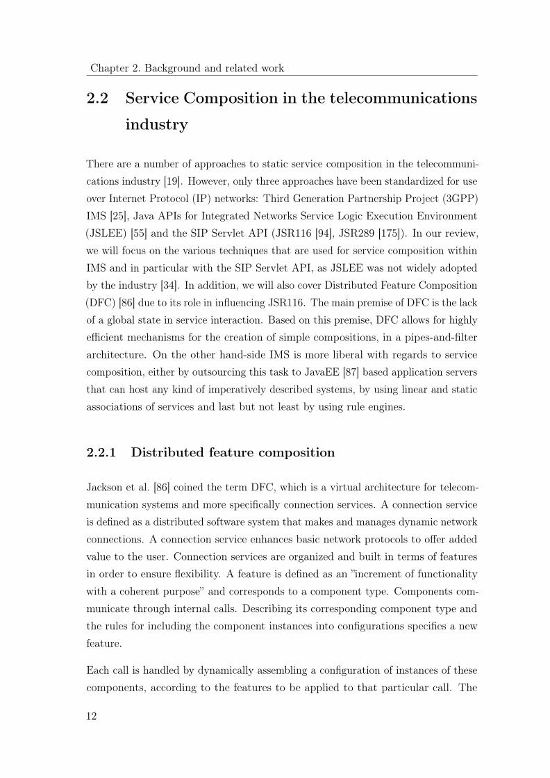
2.2.1 Distributed feature composition
Jackson et al. [86] coined the term DFC, which is a virtual architecture for telecom-munication systems and more specifically connection services. A connection serviceis defined as a distributed software system that makes and manages dynamic networkconnections. A connection service enhances basic network protocols to offer addedvalue to the user. Connection services are organized and built in terms of featuresin order to ensure flexibility. A feature is defined as an ”increment of functionalitywith a coherent purpose” and corresponds to a component type. Components com-municate through internal calls. Describing its corresponding component type andthe rules for including the component instances into configurations specifies a newfeature.
Each call is handled by dynamically assembling a configuration of instances of thesecomponents, according to the features to be applied to that particular call. The
12

2.2 Service Composition in the telecommunications industry
Figure 2.1: A simple DFC usage with two interfaces boxes (IB) and N featureboxes (FB) in each part of the network
resulting configuration is analogous to an assembly of pipes and filters were featurecomponents are independent, they do not share state, they do not know or dependon which other feature components are at the other ends of their calls (pipes), theybehave compositionally, and the set of them is easily enhanced. This relationshipis illustrated in Figure 2.1. IB stands for Interface Box and it is used to denote apiece of functionality dedicated to providing an interface to FB which stands forfeature box. Feature box contain the implementation of specific features such as’call forwarding on busy.’ Source and target are used to represent different networks(perhaps operated by different vendors) that host different features and differentinterfaces to those features.
The composition is implemented by a dynamically assembled graph of feature boxes(nodes) and calls (edges). This graph is called a usage. DFC thus leads to a pipes-and-filters architecture in which calls are the pipes and feature boxes are the filters.A source feature applies to any connection request with the appropriate sourceaddress. A target feature applies to any connection request with the appropriatetarget address. This provides an important mechanism for customization of services.Interoperation features provide conversion functions implemented as gateways toother domains.
One of the fundamental assumptions behind DFC is that features should be trans-parent. When their functions are not required they should act transparently and notinfluence the connection in any way. The pipes-and-filters arrangement gives featuresautonomy, when their functionality is required they can interrupt the connectionand carry out their function without external intervention.
The DFC approach clearly has had considerable influence on state of the art tech-nologies such as JSR116 that is described later on in paragraph 2.2.2.2.
13
Chapter 2. Background and related work
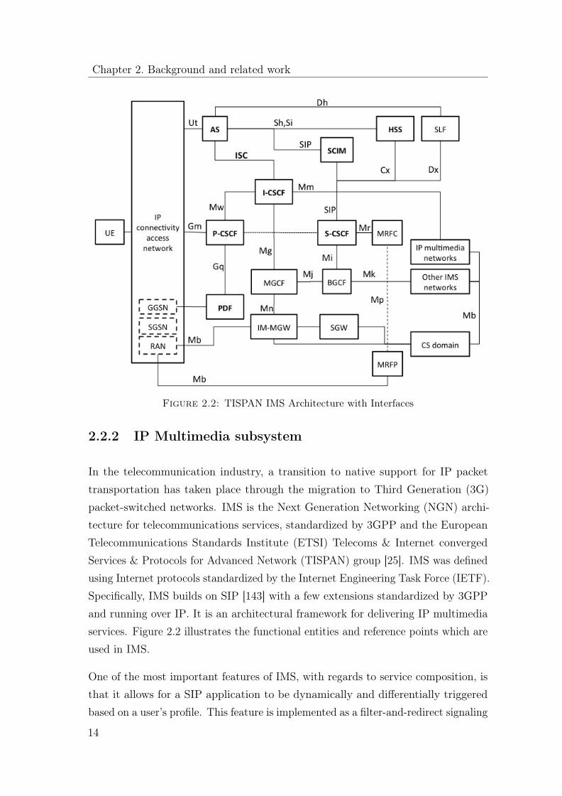
Figure 2.2: TISPAN IMS Architecture with Interfaces
2.2.2 IP Multimedia subsystem
In the telecommunication industry, a transition to native support for IP packettransportation has taken place through the migration to Third Generation (3G)packet-switched networks. IMS is the Next Generation Networking (NGN) archi-tecture for telecommunications services, standardized by 3GPP and the EuropeanTelecommunications Standards Institute (ETSI) Telecoms & Internet convergedServices & Protocols for Advanced Network (TISPAN) group [25]. IMS was definedusing Internet protocols standardized by the Internet Engineering Task Force (IETF).Specifically, IMS builds on SIP [143] with a few extensions standardized by 3GPPand running over IP. It is an architectural framework for delivering IP multimediaservices. Figure 2.2 illustrates the functional entities and reference points which areused in IMS.
One of the most important features of IMS, with regards to service composition, isthat it allows for a SIP application to be dynamically and differentially triggeredbased on a user’s profile. This feature is implemented as a filter-and-redirect signaling
14

2.2 Service Composition in the telecommunications industry
mechanism in the Serving Call Session Control Function (S-CSCF), which is analyzedin paragraph 2.2.2.4. The S-CSCF may apply filter criteria to determine the need toforward SIP requests to an Application Server (AS). At this point it is important topoint the distinction between the originating network; the network that hosts theoriginating party and the terminating network that contains the terminating party.With this distinction in mind service composition is performed in its correspondingnetwork.
Camarillo et al. [25] and Bertrand [16] provide a complete description of each entityand reference point depicted in Figure 2.2. For the purposes of this thesis, we willfocus primarly on:
• Home Subscriber Server (HSS)
• Call Session Control Function (CSCF)
• AS
• Initial Filter Criteria (iFC)
• Intelligent Network (IN)
• Charging
• Policy charging and rules functions (PCRF)
• Service Capability Interaction Manager (SCIM)
Since these nodes are the most relevant to the process of service composition whichwe are addressing.
2.2.2.1 Home Subscriber Server
HSS is a master user database that supports the IMS network entities that actuallyhandle calls. It stores subscription-related information (subscriber profiles), performsauthentication and authorization of the user and can provide information about thesubscriber’s location and IP information.
15

Chapter 2. Background and related work
2.2.2.2 Application Servers
SIP application servers (AS) are used for hosting and executing services. Dependingon the actual service, the AS can either function in a SIP proxy mode, SIP UserAgent mode (UA) or a SIP Back-2-Back user agent mode (B2BUA).
An AS can either be located in the home network or in an external third partynetwork. If it is located in the home network, it can query the local HSS using theDiameter Sh or Si interfaces. Java specification requests (JSR) such as the JSR116and JSR289 standardize the functionality of SIP application servers. The followingparagraphs, JSR116 and JSR289 provide a short descriptions of what is standardizedby the aforementioned JSRs.
JSR116 JSR116 is a SIP Servlet Specification. It standardizes the functionalityof SIP Containers. Since it is a JSR, it describes Java specific APIs for SIP Servlets.One of the goals of this specification was to provide an approach similar to thewell-known HTTP Servlets approach (JSP), so that developers can easily learn andstart using it. This basic approach introduces a SIP Container, where multiple SIPapplications consisting of SIP services can be deployed. Since it is particularly wellsuited for server-side SIP applications, this specification is usually taken as a basisfor most SIP Application Servers (e.g. SailFin [150], BEA WLSS [66], etc.).
This specification describes different aspects of SIP Servlets development, as well asdeployment and execution of the servlets on the SIP container.
For the development phase, JSR116 defines a set of SIP servlet APIs, which providea framework for the SIP servlets and formalize the method how such servlets accessthe SIP functionality, react to incoming/outgoing SIP packets and interact with theSIP container.
For the deployment phase, the specification introduces the deployment descriptorformat (e.g. SIP.xml file format), which is used to describe the set of SIP applicationsand servlets provided by a given deployment package. In addition, it defines a set ofrules that specify the conditions when the SIP applications and servlets deployed ina given package should be invoked and the order of such invocation. It is permittedand possible that the same SIP Container has several applications and servlets thatcan be invoked on the same incoming SIP packet, according to the rules described
16

2.2 Service Composition in the telecommunications industry
in their deployment descriptor. Thus, rather limited composition functionality isprovided. It allows for static composition of linear sequential chains of SIP servletsinvocations.
Moreover, JSR116 describes the behavior of a SIP container at runtime. It specifieshow the container towards the applications and servlets responsible for their pro-cessing propagates SIP requests. Moreover, it specifies the management of runtimedependencies between the SIP applications and servlets belonging to them. Thetask of managing all this runtime relationships and dispatching of SIP messages ishandled by the SIP Servlet Dispatcher.
In an effort to overcome some of the problems discovered and experienced after theintroduction of JSR1116, an update of the specification was proposed in form of aJSR289, which will be adressed in the next sections.
JSR289 JSR289 is an attempt to extend the SIP servlets specification. Extensionstake into account experiences gained with JSR116. One of the very popular featuresasked by many participants of JSR and practitioners is an improved support forcomposition of SIP services. There are requests to make it more dynamicallyconfigured, to clarify some parts of JSR116 and make them more precise, and toimprove the possibility to interact with other technologies (e.g. Enterprise Java Bean(EJB)s, Web Services, HTTP Servlets) deployed on the same application server.
2.2.2.3 BEA WebLogic SIP Server
A SIP servlet container, according to the JSR116 standard, hosts servlets accessiblevia SIP. Moreover, it provides the means of creating chains of servlets. This is meantto allow the composition of more complex services as chains out of individual servlets.Consequently, the SIP container acts for the SIP services it hosts as a compositionexecution engine. Currently, most SIP servlet containers implementing JSR116 usea static composition approach. The equivalent to composition creation takes placemanually at deployment time and is static in the way that it cannot be changedwithout a change in the configuration of the container.
Advanced solutions are slightly more dynamic. BEA WebLogic SIP Server (WLSS)tries to move the split between composition creation and composition execution
17

Chapter 2. Background and related work
Figure 2.3: BEA WLSS SIP Servlets composition
towards the runtime phase by introducing a special composer servlet. The composerservlet always acts as the first component of the composition. This servlet effectivelyperforms service creation based on algorithms hard-coded during its design andpossibly by consulting external nodes or databases. However, changes to the createdchain of SIP services are no longer possible after composition execution starts.
2.2.2.4 Call Session Control Function (CSCF)
An IMS core consists of three different CSCFs:
• Proxy-CSCF (P-CSCF)
• Serving-CSCF (S-CSCF)
• Interrogating-CSCF (I-CSCF)
These three entities are based on SIP application servers and are used to process SIPsignaling packets in IMS. A CSCF is similar to a Mobile Switching Center (MSC) in
18

2.2 Service Composition in the telecommunications industry
the Global System for Mobile Commnunications (GSM) domain, with the additionalcapability of supporting multimedia sessions along side voice calls. Moreover, CSCFscan generate Call Detail Records (CDR)s for charging and billing purposes.
Proxy-PCSF The P-CSCF is the first point of contact in an IMS terminal. Assuch, it is assigned to an IMS terminal before registration and does not changefor the duration of the registration. It is positioned in the signaling path and caninspect every signal. It provides subscriber authentication and it can be used toprevent spoofing and replay attacks in order to protect the privacy of the subscriber.Moreover, it supports compression, thus reducing the round-trip over slow radiolinks. Finally yet importantly, it may include a Policy Decision Function (PDF) thatauthorizes media plane resources such as Quality of Service (QoS) over the mediaplane.
Serving CSCF The S-CSCF is located in the home network and its purpose isto perform session control and registration services for physical devices or terminals(user endpoints). As such, it handles SIP registrations, which allows it to bind theuser location (e.g., the IP address of the terminal) and the SIP address. It sits onthe path of all signaling messages of the locally registered users, and can inspectevery message. It decides to which application server(s) the SIP message will beforwarded, in order to provide their services. Finally, it provides routing services,typically using Electronic Numbering (ENUM) lookups. It enforces the policy of thenetwork operator.
There can be multiple S-CSCFs in a network for the purposes load distributionand high availability. It’s the HSS that assigns the S-CSCFto a user, when it’squeried by the I-CSCF. There are multiple options for this purpose, includingmandatory/optional capabilities to be matched between subscribers and S-CSCFs.
Interrogating-CSCF Interrogating Call Session Control Function (I-CSCF) isused as a contact point for all connection destined to a user related to this networkoperator, or a roaming user within the operators service domain. It queries the(HSS) to retrieve the address of the S-CSCF and assign it to a user performing aSIP registration. Moreover, it forwards SIP requests or responses to the S-CSCF.
19

Chapter 2. Background and related work
2.2.2.5 Initial Filter Criteria (iFC)
From a SOA perspective, IMS uses a simple orchestration mechanism in order toselect the additional services that are needed within a telecommunication session [44].This mechanism relies on iFC. iFC are filter criteria that are stored in the HSSas part of the IMS Subscription Profile and are downloaded to the S-CSCF uponuser registration (for registered users) or on processing demand (for services, actingas unregistered users). They represent a provisioned subscription of a user to anapplication. iFCs are valid throughout the registration lifetime or until the UserProfile is changed. The term Shared iFC denotes an iFC, which, due to its commonuse for a large number of subscribers, is only referenced in the Subscription Profileand provisioned on a different path between the HSS and the S-CSCF.
An iFC is composed of:
• An Application Server Uniform Resource Identifier (URI) where the request isto be forwarded in case of a match.
• A Trigger Point in the form of a logical condition that is verified against initialdialog creating SIP requests or stand-alone SIP requests.
As such, iFCs are specific to a user and represent a list of services to be invoked.This method is not dynamic; the services that a user might need are placed in thechain of services regardless of their usefulness for a given session. Service interactionis managed in the most basic way by manually defining service combinations andiFCs so that it works without causing any interaction problems.
2.2.2.6 Intelligent Networks (IN)
The aim of IN was to enhance core telephony services offered by traditionaltelecommunications networks, which usually amounted to making and receivingvoice calls, sometimes with call divert. This would then provide a way for operatorsto build services in addition to those already present on a standard telephoneexchange. Later a new variant of IN standard evolved. This variant was calledCustomized Applications for Mobile networks Enhanced Logic, or CAMEL for short.
20

2.2 Service Composition in the telecommunications industry
Figure 2.4: IN architectural components
This allowed for extensions to be made to the mobile environment, and allowedmobile phone operators to offer the same IN services to subscribers whilst they areroaming as they receive in the home network.
IN represents a nice example of a static service composition with a clear separationof the service creation and service execution phases.
Service Switching Function (SSF) or Service Switching Point (SSP) is co-locatedwith the telephone exchange itself, and acts as the trigger point for further servicesto be invoked during a call. In this sense, it plays the role of a dispatcher.
The SSP implements the Basic Call State Machine (BCSM) that is a Finite StateMachine (FSM) that represents an abstract view of a call from beginning to end(off hook; dialing; answer; no answer; busy; hang up etc.). Consequently, the SSFmaintains the overall state that allows it to make decisions regarding the executionof the service.
For each state (and corresponding Detection Points) the SSP can signal the ServiceControl Point for further instructions on how to proceed. This is called a trigger.Trigger criteria are freely defined based on related data such as the subscriber callingnumber or the dialed number.
The Service Control Function (SCF) or Service Control Point (SCP) is responsiblefor the execution of compositions. It contains service logic which implements thebehavior desired by the operator as a form of static service composition. Duringservice logic processing, additional data required to process the call may be obtained
21

Chapter 2. Background and related work
from the Service Data Function (SDF). The logic on the SCP is created using aService Creation Environment (SCE).
The SCE is the development environment used to create the services on the SCP.Although any type of environment can be used for development, low-level languageslike C are rarely used. Proprietary graphical languages are used often to enabletelecom engineers to create services directly. These services represent essentiallystatic service compositions, which cannot be modified or extended during execution.
SDF or Service Data Point (SDP) is described in subsection 2.2.2.7.
Specialized Resource Function (SRF) or Intelligent Peripheral (IP) is a node thatcan connect to both the SSP and the SCP and delivers additional special resourcesinto the call. Examples of such resources are play voice announcements or collectDual Tone Multi-frequency Signalling (DTMF) tones from the user.
2.2.2.7 Charging System
A charging system is consisted of two nodes that help compose appropriate chargingfor the requested services. The Charging Control Node (CCN) enables charging forGeneral Packet Radio Service (GPRS), Short Message Service (SMS) and content-based services. This system can be used as a stand-alone node or as part of theoverall Charging System. The SDP on the other hand is responsible for rating callsand events, post processing of CDR and initiation of Unstructured SupplementaryService Data (USSD) notifications. Depending on the service type, the CCN acts asa relay between the core network MSC, Gateway GPRS Support Node (GGSN) andthe Serving GPRS Support Node (SGSN), service and Multi Mediation network (e.g.MMC), and SDP that is the part of the Charging System. This element supportsthe following services in the Charging System:
• Online charging of GPRS and SMS using Camel Application Part Version 3(CAPv3) API
• Online charging of Content and Event, using the Diameter protocol [24]
• The Policy and Rating Server (PRS) using the Diameter protocol
• Relay of Charging Based Service Control Signalling System Version 7 (SS7)
22

2.2 Service Composition in the telecommunications industry
Call acc .
Community ID Dedicated Acc . Accumulator Rating Bonus
USSD EoCN
CallHandler
Subscr .IF
Rating
C.ID C.ID, DA.
C.ID, DA, Acc .
Hello
Call acc .
Community ID Dedicated Acc . Accumulator Rating Bonus
USSD EoCN
CallHandler
Subscr .IF
Rating
C.ID C.ID, DA.
C.ID, DA, Acc .
Hello
Figure 2.5: SDP-PSC Selection Tree Component
The CCN node utilizes different charging and control rules depending on the servicetype, e.g. online charging of GRPS traffic either is done according to connectionduration or transferred volume. A configurable conversion factor allows performingconversions between time and volume. CCN can be parameterized to provide differentfunctionalities depending on the operators’ needs. This feature characterizes otherCharging System nodes and allows operators to deliver new market offers evenwithout additional implementation efforts.
The charging SDP on the other hand takes decisions regarding which tariff to use ina particular situation dynamically during runtime. This is achieved by a selectionmechanism that uses the data stored in selection trees, as well as data on thesubscription of the user and the requested service to ”compose” the appropriate tariff.Therefore, this approach can be considered as a specialized form of composition.
SDP holds or administers: subscriber data, account data, service class data, an-nouncement class data, usage accumulators data, tariff and charging analysis data,subscriber life-cycle data, dedicated accounts data, license management data, USSDand SMS notifications, promotion plan data, Home Location Register (HLR) blockingdata and community data.
These trees are managed by a dedicated service component that is used for takingdecisions based on the trees it manages for many of the functions of the SDP.This decision support function implements both tree management functionality to
23

Chapter 2. Background and related work
Rx
Gx
PCRF
P-CSCF
GGSN
SIP
Figure 2.6: 3GPP standardized view of PCRF deployment
edit and test data, e.g. via Tariff Management, as well as flexible mechanisms toselect/calculate and return data.
2.2.2.8 Policy charging and rules function (PCRF)
PCRF function is a software node designated in real-time to determine policy rules ina multimedia network. EPC is Ericsson’s implementation of the 3GPP PCRF node.The EPC is developed and tested in a platform agnostic environment using POSIXstandards. EPC 1.0 and 2.0 are integrated in Ericsson’s proprietary operating systemDicos [54].
EPC 1.0 interacts with the Service Aware Support Node (SASN) using the SRAP/Di-ameter draft8 interface. Later versions that will integrate SASN with the GGSN willhandle this communication over the Gx interface. EPC 2.0 interacts with externalentities using Rx & Gx Diameter based interfaces and old EPC 1.0 for migrationsupport. Both EPC 1.0 and 2.0 are integrated with the P-CSCF and collapse theRx interface. Rx support was added in 2007 to support separate P-CSCF and otherentities supporting the Rx interface (e.g. streaming server). EPC can be deployedas shown in Figure 2.6.
The EPC contains a rule engine used to evaluate rules and policies towards makingdecisions about which policy to apply in a specific situation. Policies and objects
24

2.2 Service Composition in the telecommunications industry
are stored in the Dicos built-in database (DBN) and can be manipulated throughLightweight Directory Access Protocol (LDAP) interfaces.
EPC policies are comprised of rules and described in a proprietary language, whichis a subset of Ecmascript [48]/Javascript. Rules can use objects in DBN and objectsdefined in external LDAP. The internal DBN cannot be expanded at runtime;therefore, new objects cannot be added at runtime. However, this can be achievedusing external LDAP repositories. Conflicting results can be resolved using variousconflict resolution algorithms. In addition, conflict resolution can be applied betweenpolicies (which algorithm to use is decided by the policies themselves).
The EPC does not impose a selection mechanism for data, which makes the ruleengine flexible and expandable. The data to select which policies to use is arrangedbetween the requestor and a policy locator.
2.2.2.9 Service Capability Interaction Manager (SCIM)
SCIM was introduced in 3GPP TS 23.002, as a function within the SIP ApplicationServer domain of the IMS architecture. The role of the SCIM is that of a servicebroker in more complex service interaction scenarios than can be supported througha service filtering mechanism. As an example, feature interaction managementprovides intricate intelligence, such as the ability to blend Presence and other networkinformation, or more complex and dynamic application sequencing scenarios.
The SCIM as proposed to the 3GPP uses IP Multimedia Service Control (ISC)and SIP interfaces to enable composite service behavior leveraging simpler servicecomponents. Consequently, service composition functionality as encountered in aSOA is well suited for implementing the SCIM function.
One could therefore envisage the SCIM to be a programmable engine, that implementsservice composition functionality enabling the creation and execution of compositeservices. Typically, such engines are implemented based on a data-driven approachi.e. rules-based or model-driven approach.
The term SCIM actually refers to an entire class of functions and not to a singlenode that handles this broad problem. Consequently, one can assume that SCIM
25

Chapter 2. Background and related work
functionality can be implemented in a number of different components each addressingdifferent requirements.
Different SCIM types can be broadly classified into the following three categories:
• AS Internal Function. A SCIM implemented as a request dispatcher withinthe local execution environment. This would be similar to function of thedispatcher in a JSR116 SIP servlet container. More SCIM like functionalitywould therefore fall within the scope of the dispatcher in JSR289.
• Format Controller. A SCIM that is developed and optimized for supportingone particular communications service. Such a SCIM could be embedded inthe implementation of a service format.
• General Purpose SCIM. This type of SCIM manages interaction betweencomponents that implement SIP proxies or user agents, service capabilities thatare exposed using WSDL and SOAP-based abstractions of the IMS networkor SIP features and legacy signaling system components.
2.3 Web service composition
Web service composition consists of a collection of approaches that either automati-cally generate a workflow based on a given problem description, or require a manualdefinition of a workflow from a designer, and thereafter complement the servicecomposition process at runtime. In this section, we divide web service compositionin three categories:
• Static
• Artificial Intelligence Planning
• Domain-specific language based
The following subsections ( 2.3.2, 2.3.3, 2.3.4 ) focus on describing the main char-acteristics of each category. Prior to these descriptions, we provide a brief introto workflow languages such as Web Services Business Process Execution Language
26

2.3 Web service composition
(WS-BPEL) and Business Process Model and Notation (BPMN) 2.0. This input isimportant for two reasons:
1. These languages are standardized, they are widely used and they posses formaldescriptions describing the semantics of their execution
2. The form a common denominator for most composition approaches, since theresult that is produced by the aforementioned methods is usually expressed asa workflow described in these languages and is later on sent on to be executedat runtime by the corresponding execution framework.
2.3.1 Workflow languages
2.3.1.1 WS-BPEL
WS-BPEL [42] or BPEL for short is the de-facto standard to describe workflows inWeb service environments. A BPEL process is built using basic and structural activ-ities. Basic activities are responsible for the communication with the environment orthe transformation of data. An invoke activity, for example, is used to invoke otherWeb services or BPEL processes. Another example would be an assign activity thatis used to copy data within a BPEL process. An example for a structural activity isthe while-loop activity.
BPEL processes are executed on top of the Web services layer. They use Web servicesfor calculations and orchestrate them to get a more complex solution. Due to thetight coupling WS-BPEL has with Web Services, it is not applicable to heterogeneousservice environments directly. However, indirectly, one can always implement a Webservice based adapter on top of the original technology used for a service and thusmake it accessible to BPEL. BPEL as such lacks a graphical representation. Thus,for business process designers with no IT background the learning curve may besteeper that with other languages. BPEL has been standardized by the Organizationfor the Advancement of Structured Information Standards (OASIS) and is widelyused in the industry.
27
Chapter 2. Background and related work
2.3.1.2 BPMN 2.0
We chose the language named BPMN 2.0 [174] because in contrast to the first versionof this language (1.0), version 2.0 has well-defined execution semantics. A BPMN 2.0process consists of a set of tasks that are connected by control connectors. BPMN2.0 has been built with Petri Nets in mind. Thus, it contains additional constructsthat are called gateways. Gateways are used to split or join the control flow withina BPMN 2.0 process. Apart from that, a mapping from a subset of tasks of BPMN2.0 to BPEL has been described in the specification of the language. It is necessaryto define a subset of BPMN 2.0 to be mapped to BPEL because even in version2.0 of BPMN it is possible to define process models that cannot be executed by aworkflow engine. It is, for example, possible to create a process model that ends in adeadlock. The mapping from BPMN 2.0 to BPEL implies that BPMN suffers fromsimilar issues with regards to its applicability to heterogeneous service environmentsand therefore it cannot be used directly in such contexts. The usability of BPMN2.0 is better than that of BPEL because BPMN comes with a standardized graphicalnotation with well-defined execution semantics. The Object Management Group(OMG) standardized BPMN 2.0.
2.3.2 Static approaches
Static approaches (also known as syntactic or manual) require the designer to buildan abstract process model out of which a specialized framework will produce aservice composition. That model includes a set of tasks and their input and outputparameters. A task may contains a query clause that is used to search for the realatomic Web service that fulfills the desired task. At runtime, a framework does theselection and binding of the corresponding atomic Web service automatically usinga service repository such as the Universal Description, Discovery and Integration(UDDI) [41]. The most commonly used static method is to specify the processmodel as a directed graph. An example of such an approach is Eflow [28]. Assuch, Eflow employs a search recipe in order to resolve which search is neededfor each node at runtime. Another approach to static composition is proposed byGronmo et al. [70]. The authors propose using Unified Modeling Language (UML)as the integration platform for Web service composition. The method utilizes a
28

2.3 Web service composition
two-way mapping between WSDL service description and a WSDL-independentservice model in UML. This mapping allows automating the transformation of WSDLdescription to UML models and vice versa. The weight in this approach falls intothe discovery of appropriate services. Once the service has been discovered, theprocess of composition is done manually via UML modeling.
A special variant of static composition produces service composition model expressedin workflow language such as WS-BPEL or BPMN out of the abstract model describedpreviously by the designer. WS-BPEL and BPMN are XML-based standards used todescribe the specification of Web services, their flow composition and execution. Bydefault WS-BPEL and BPMN use static service discovery, which is implemented bythe partner link element. This means that every execution of an external service istightly coupled at design-time to a particular external service at XML/XSD level. Inorder to overcome this limitation for the purposes of service composition, dynamic,query language based [125], or even adaptive publish-find-bind approaches [112] areused at runtime in order to permit the underlying framework responsible for theexecution of the workflow to query the UDDI and allow for runtime selection andsubstitution of services.
A further improvement found in the state-of-the art for static service compositionis the usage of ’semantic suggestions’ for service selection during the compositionprocess; the designer still needs to select the service required from a shortlist of theappropriate services and link them up in the order desired. This variant is oftenreferred to as semi-automatic web service composition. Sirin et al. [151] proposea system that provides service choices that are semantically compatible at eachstage. The generated workflow is then executed. Cardoso and Sheth [27] propose aframework that provides assistance to the user by recommending a service meetingthe user’s needs. This is done by matching the user specified Service Template (ST)with the Service Object (SO).
A further improvement found in the state-of-the art for static service compositionis the usage of ’semantic suggestions’ for service selection during the compositionprocess; the designer still needs to select the service required from a shortlist of theappropriate services and link them up in the order desired. This variant is oftenreferred to as semi-automatic web service composition. Sirin et al. [151] proposea system that provides service choices that are semantically compatible at each
29
Chapter 2. Background and related work
stage. The generated workflow is then executed. Cardoso and Sheth [27] propose aframework that provides assistance to the user by recommending a service meetingthe user’s needs. This is done by matching the user specified Service Template (ST)with the Service Object (SO).
2.3.3 Artificial Intelligence Planning
From an Artificial Intelligence (AI) planning point of view, web service compositioncan be perceived as the construction of a process to attain a specific goal. As such,the problem of service composition is transformed to an AI planning problem thathas been extensively investigated by the AI community since the early days of AI.The definition of an AI planning problem is given by Russel et al. [142]; Givena description of the initial state of the world, a description of the desired goal,and a description of the possible actions that can be executed, the purpose of anAI planning algorithm is to construct one or more paths that lead to a certaingoal. More formally, this problem can be described as a tuple with five elements:(S, S0, G,A,G
′) where S is the set of all possible states of the world, S0 ⊂ S anddenotes the initial state of the world, G’ and denotes the goal state of the world, Ais the set of actions the planner can perform and G’ is the relation G′ ⊂ S x A x S.
The following subsections describe different computation models that can be usedfor AI planning of service composition. These computation models are: Finite StateMachines (FSM), Situation Calculus, Hierarchical Task Networks and Petri nets.
2.3.3.1 Finite State Machines
A FSM is a model of computation, that models behavior of a finite number ofstates and transitions between those states and actions. Berardi et al. [15] focuson services whose schema can be represented as a FSM and propose an algorithmthat checks for the existence of a composition. Bultan et al. [22] utilize a MealyMachine; an extended FSM that generates an output based on its current state andadditionally an input. According to this approach, services communicate by sendingasynchronous messages and each service has a queue. A global watcher keeps track ofall messages. The conversation is introduced as a sequence of messages. By studying
30
2.3 Web service composition
and understanding conversation properties, this method provides new approachesfor designing and analyzing well-formed service composition.
2.3.3.2 Situation Calculus
Situation calculus is a logic formalism introduced by McArthy [106]. It is usedto model a dynamic world as a progression of a series of situations, consequencesof various actions performed within the world. The calculus is consisted of threeelements: the actions that can be performed in the world, fluents that describe thestate of the world and the situations. Narayanan et al. [117] provide a limited set ofassumptions, under which Web service composition can be realized as a process ofreasoning about action formalisms modeled in Situation Calculus. A popular toolwhen working with Situation Calculus is Golog [98]; a high level logic programminglanguage, built on top of Situation Calculus, for the specification and execution ofcomplex action in dynamic domains. McIllraith et al. [110] propose a method thatmakes uses of software agents that deal with reasoning about Web services to performautomatic Web service discovery, execution, composition and inter-operation. Theproposed method is built on an extended version of Golog that provides knowledgeand sensing actions in order to become a suitable formalism for representing andreasoning about the Web service composition problem.
2.3.3.3 Hierarchical Task Networks
Hierarchical task network (HTN) planning [97] is a method of planning in the formof task networks. As such, it differs from other planning methods since it focuses ontasks instead of states. An HTN based planning system operates in a continuousloop. In the duration of this loop, a task is constantly decomposed into a set ofsub-tasks until the resulting sub-tasks are decomposed to such an extent, that theyhave become primitive tasks and can therefore be executed directly. In each step,during this process of decomposition, tests are made in order to check if conditionsare violated. The continuous loop terminates if that is the case, if a condition isviolated or if the process of decomposition has reached the level of primitive sub-tasks.HTN planning is re-purposed by Sirin et al. [152] for the process of Web servicecomposition in a tool called SHOP2 that uses DAML-S Web service descriptions.
31

Chapter 2. Background and related work
2.3.3.4 Petri nets
A Petri Net (short for Place/transition net) is a connected and bipartite graph. It isconsisted of places, transitions and arcs. Arcs run from a place to a transition orvice versa and never between places or between transitions. The places from whichan arc runs to a transition are called input places while the places to which arcsrun from a transition are called output places of the transition. A Petri Net mayfire if it is enabled; when there is at least one token in every place connected to atransition. Hamadi et al. [77] re-purpose Petri nets for Web service composition. Intheir approach services are modeled as Petri nets by means of mapping. Petri nettransitions are mapped to methods and places are mapped to states. Each service,represented as a Petri net has two ports: one input place and one output place. Atany given time, a service can either be non-instantiated, ready, running, suspendedor completed. After the transformation of each service to a Petri net, compositionoperators are used in order to combine different services.
2.3.4 Domain specific language based approaches
The approaches presented in this subsection, rely on Domain Specific Language(DSL)s that aim at capturing richer aspects of service composition that go beyondthe plain structure of the messages exchanged, thereby associating semantic contextto messages. These approaches are Semantic Annotations, the Planning DomainDefinition Language (PDDL), Knowledge-based, rule-based, pattern-based, Agent-based and finally Service Level Agreement based.
2.3.4.1 Semantic Annotation
Web service descriptions such as WSDL are limited into describing only the essentialparts that are need by SOAP for the purposes of message exchange between the serverthat holds the endpoint of a service and a client that consumes that service. Semanticannotations aim at compensating for this deficit by permitting the association ofmeta-data to Web service descriptions by means of ontologies. This associationenables coupling a multitude of Semantic Web languages to Web service descriptions.A few examples of ontology languages are DAML+OIL [85] and OWL [109]. When
32

2.3 Web service composition
it comes to Web services languages OWL-S [104] (formerly DAML-S [7]) can beused which is an extended version of OWL. On top of OWL’s main constructs,OWL-S has a Service Profile, a Process Model and Grounding to describe a Webservice. These additional constructs can be used by software agents for the purposesof discovering and using a service. The METEOR-S framework, proposed by Patil etal. [130] is the most cited approach for semi-automatic annotation of Web services.
2.3.4.2 Planning Domain Definition Language (PDDL)
The Planning Domain Definition Language is a widely recognized standard used byplanners that has influenced DAML-S and as such it can be very easily mapped toand from DAML-S as long as only declarative information is concerned. In 1998McDermott et al. [107] introduced the first version of this language, which hassince then reached to version 3.1 [92]. The obvious advantage here is that as longas the designer uses this language, any PDDL-compliant planner can be used inthe process of composition. To deal with Web services specifically, McDermott etal. [108] introduce a new persistent knowledge type that is called a truth literal.This allows the system to interpret that old states disappear and new states areproduced.
2.3.4.3 Knowledge-based
Knowledge based composition is a similar process to that used by expert systems suchas CLIPS [64]. In such systems, a domain-specific language is used to formulate acommon vocabulary that captures the terms that represent an experts understandingof a particular field. In the case of service composition, the field is that which definesthe properties of the different services to be composed, for example, if we are lookinginto knowledge-based composition for the purposes of traveling, then the particularlanguage will contain constructs related to reservations, means of transportation etc.An example of knowledge-based composition is provided by Chen et al. [31]. In thiswork, the authors utilize domain specific knowledge to guide the process of servicecomposition.
33

Chapter 2. Background and related work
2.3.4.4 Rule based
Rule-based approaches also employ domain-specific languages in order to describesets of antecedents and consequents to govern the process of service composition.Medjahed et al. [111] propose a composability model that checks which Servicescan interact with each other. The proposed model has four phases. The specificationphase uses Composition Service Specification Language (CSSL) for the descriptionof composite services. The matchmaking phase uses a set of composability rules todescribe that different matches among services based on their composability. Theselection phase ranks the different matches that have been in the previous phase inorder to select the most appropriate one. Finally, the generation phase outputs thedescription of a composite service. Other commercial rule based approaches suchas DROOLS [13] employ RETE algorithms [58] in order to identify very efficientlywhich rules are affected by the specific event at hand. As such they can be used forthe purposes of event-based service composition.
2.3.4.5 Pattern-based
While rule-based approaches are based on logical expressions, pattern-based ap-proaches employ techniques such as software patterns, workflow patterns, collab-orative filtering and statistical expression, to formulate characteristics that whenidentified should result into certain actions. Examples of pattern based compositionare reported in [163, 178, 30, 162]. What is interesting to note regarding theseapproaches is that the process of service composition, through patterns, acquires amore predictive facet and as such it is no longer limited to pre-defined constructsand can therefore utilize probabilistic techniques.
2.3.4.6 Agent-based
Mobile agents, like most agent-based approaches make use of autonomous entitiescalled agents in order to achieve a goal. In some cases the goal may be achievedby an agent work on their own while in other cases when different agents arecollaborating towards the same goal. The usage of mobile agents is encountered inErmolayev et al. [53] work. The authors here use semantic annotations in order to
34

2.4 Summary
describe a common language (therefore a protocol) that is used for the purposes ofcommunicating between different agents. In this context, an agent has the capabilityof discovering services by means of a registry or by asking other services in a peer-to-peer manner. The main benefit of the proposed approach is that service compositionis no longer centrally governed by a workflow. However, the added benefit comes atthe expense of additional message exchange. Cheng et al. [32] further refine on theusage of agents in service composition by proposing an Agent Service DescriptionLanguage (ASDL) for describing the behavioral characteristics of a Web service, asopposed to its external behavior that is described in WSDL. In this context, behaviorrefers to the permitted sequence of invocations that are allowed by an agent.
2.3.4.7 Service-Layer agreement based
Service layer agreement based composition or SLA-based composition employspolicies expressed in domain specific languages in order to define the requiredcharacteristics of a service composition. This notion is used in [136, 37]. Thecommon characteristic of such frameworks is the usage of breadth-first or depth-first algorithms during the process of exploring the search space for the possiblealternative implementations of a composite service that lives up to the requirementsdescribed by the SLA. As such they utilized dynamic algorithm that may not alwaysyield a solution in PTIME [127].
2.4 Summary
There is an abundance of service composition approaches in the state of the art.This section aimed at identifying their key characteristics for the purposes of betterunderstanding what is currently available. Based on those characteristics, existingapproaches are grouped in the following categories:
1. Static approaches
2. Artificial Intelligence Planning
3. Domain-specific language based
35

Chapter 2. Background and related work
Service composition approaches used within the telecommunications industry relatemore closely to Static approaches since they model the process of service compositionmanually. These approaches are Distributed Feature Composition, Initial Filter Cri-teria, Intelligent Networks and JSR116/JSR289. The key benefit of such approachesis explicit control, since the developer of the composition can very directly controlall the aspects of service composition, such as the execution flow and the differentservices that are being used. Techniques used for Charging and Policy charging andrules functions (PCRF) are more closely related to the domain-specific languageapproach.
The Domain specific language based category is split into seven subcategories: Se-mantic Annotations, the Planning Domain Definition Language (PDDL), Knowledge-based, Rule-based, Pattern-based, Agent-based and finally Service Level Agreementbased. The approaches within this category examine service compatibility, take intoaccount both functional and non-functional requirements and allow reasoning onwhich component is best to use in each situation.
Finally yet importantly, the artificial Intelligence planning category is split into foursubcategories based on the different computation models that are being used: FiniteState Machines, Situation Calculus, Hierarchical Tree Networks and Petri nets. Assuch the approaches in this category deal with the problem of service composition as aplanning problem, where the formal properties of the aforementioned computationalmodels are used in order to define the sequence of atomic services which whencombined can achieve a certain goal.
36

Chapter 3
The approach
Our approach to the problem of service composition is the following:
• Identify the requirements for service composition in a heterogeneous servicelandscape (section 3.1)
• Assess and discuss to which extent these requirements are met by the state ofthe art approaches presented in Chapter 2 (section 3.2)
• Based on the previous assessment provide a set of guiding concepts and centralobjectives for the proposed approach (section 3.3)
3.1 Service composition requirements
The list of requirements has been compiled by aggregating challenges in servicecomposition both from the academic state of the art and also from the telecommuni-cation industry. More specifically, through the process of interviews, the experiencesof Ericsson software engineers who have been actively working in system integrationactivities in the telecommunications domain was recorded. Out of this processthree major requirements have immersed; the need for unified application routing( 3.1.1 ), support for concurrency ( 3.1.2 ) and last but not least more flexible typechecking techniques ( 3.1.3 ). The following subsections further elaborate on theserequirements.
37

Chapter 3. The approach
Business Process Execution
Figure 3.1: Service usage in Web service orchestrations
3.1.1 Unified application routing
Application routing as applied in telecommunication networks such as IMS is fun-damentally different from web service composition [18]. In order to find the keyrequirements on a converged composition technology, it is necessary to better under-stand the similarities and differences between the two approaches.
In web service composition, web services are invoked following a request-responsescheme. Requests are explicit and target a specific web service to be executed. Aweb service may be composite and as such it can be consisted of additional atomicweb services. Therefore, web service composition as a whole can be illustratedas a hierarchical tree structure, with the composition process at each level underthe control of a single business entity (Figure 3.1). Parallel processing and servicerequests, which may be received and processed by participants of the compositionin any order or even in parallel, are possible as long as explicit execution orderingdependencies are fulfilled. Ultimately, all services are invoked to serve one particularuser request.
In contrast, within the telecommunication domain multiple parties or users are in apeer-to-peer relationship. This is reflected in telecom applications being composedas a chain structure (Figure 3.2) (also reffered to as service chain). This chainrepresents an end-to-end signal flow between telecommunication session participants,with the services allocated as logical nodes on the chain. Each service in the chainhas a persistent connection, i.e. a SIP dialog, with its immediate neighbor without
38

3.1 Service composition requirements
Telecommunication Session Control(e.g. IMS)
Figure 3.2: SIP service chaining
being aware of its neighbor’s function. Thus, the service participates actively in thesession signaling. In order to manage this service chain, sessions that span fromendpoint to endpoint and across multiple nodes and networks are a central concept.
When establishing a telecommunication session between multiple parties, no servicesare explicitly specified. However, each of these parties may have services definedaccording to their particular needs. This view is user (endpoint) centric. The servicesthat a user is subscribed to are invoked implicitly during session establishment. Theapplication chain may traverse multiple administrative domains, thus different nodesmight compose different segments of the chain.
Furthermore, multiple parties may imply competing requests and multiple servicesmay be invoked on the same triggering condition resulting in overlapping functionality.In this respect, chains represent a very sequential structure and correct ordering ofservices is essential for service interaction. For a unified service composition approachthis means that the session concept, with its characteristic logical allocation andcontrol of services, and a possibility to solve and control service interaction, needsto be supported next to the explicit invocation in a request-response scheme.
Within a telecommunication context, there are real-time requirements originatingin the timing requirements of SIP as well as in user requirements. For example,post-dial delay (the duration that extends between the end of dialing and receivinga call progress tone) is typically bounded. In contrast, a best-effort response time istypically required from web services. Predictable behavior regarding non-functionalrequirements, and therefore their control, is needed within converged compositeapplications.
39
Chapter 3. The approach
In the web domain, web services can be invoked synchronously or asynchronously.In either case, the composition node is maintaining the interaction relationship withits invoked modules for the duration of their respective invocations. Furthermore,they can be invoked in parallel or in an order that best satisfies the requirementsof the implemented application. The services are typically not aware of each other,thus they do not interact directly with one another, but only through the centralcomposition node. For a controlled interaction with the services, the compositionnode maintains state across service invocations, whereas a module it invokes normallydoes not maintain state after returning. In this way, a module can be seen to existonly for the duration of its interaction with the composition node.
In contrast, telecommunication services are invoked sequentially and operate asyn-chronously. An application router is invoked by reception of an initial SIP message.It invokes a service by forwarding this initial SIP message to the service. The nextservice in the sequence will be invoked after the previously invoked service issues aninitial request to the application router. Subsequent to their invocation, the servicesexchange SIP messages in-between themselves to directly interact with each other.A central application router is only needed in the session establishment. Thus, itusually does not need to maintain extensive session state. The services themselvescontain state related to the SIP signaling channel they are participating in.
What emerges from this comparison is that the process of service composition for webservices and telecommunication services are significantly different. An applicationrouter invokes its telecommunication features in a sequence, considering featuresinteraction via messaging over a SIP signaling channel that the application router isnot privy to; and composition response time has soft real-time constraints. On theother hand, a composition node for web services interacts over the lifetime of theservices with messages exchanged only between a service and the composition node,not between services. Web service composition response time is best effort.
With an understanding of how these two approaches differ, we can now identifywhat is required from a converged composition mechanism:
1. A mechanism that permits interaction with a persistent telecom service afterhaving returned from invoking it. This motivates the introduction of the”composer” logical functionallity. As such this would enable the composer to
40
3.1 Service composition requirements
be informed of state updates that may occur in the telecommunication domainin response to receiving SIP messages along the separate signaling channel.Moreover, it would enable the composer to influence both telecom and webmodules after their invocation.
2. A lightweight module invocation mechanism that supports real-time limits.
3. Support for managing service interaction that naturally arises amongst com-posed services.
On top of these requirements, telecommunication network operators need extensivecontrol over the services they allow to be provided through their network. Controlledservice behavior and service quality are important in this respect, in order to keephigh standards regarding reliability and availability of a single service offer or theentire network. Furthermore, inter-operability between networks and nodes need tobe ensured by following appropriate standards.
3.1.2 Concurrency
Concurrent computing is as a well-known form of computing in the state of theart, where programs and functions thereof are expressed by means of processes orthreads and may be executed in parallel. In most cases parallel execution is eitherachieved via time-slicing techniques or by utilizing one or more processors that areassigned with different tasks (or computations) to be executed at the same time. Asa consequence, communication between different processes or threads becomes animportant aspect.
There are two main paradigms with regards to explicit communication, sharedmemory and message passing communication.
• Shared memory communication is exemplified in languages such Java and C#and allows for communication between processes via altering contents of acommon and mutually shared memory space. To avoid unwanted changestechniques such as semaphores and mutexes are used to coordinate betweenthreads.
41
Chapter 3. The approach
• Message passing communication has become popular through languages suchas Erlang and Scala. In such languages messages are exchanged asynchronously– this defeats the need for locking shared resources and is considered morerobust than shared memory communication.
Several concurrent programming languages exist, D [4], Comega [17], Erlang [10],Orc [90], Plaid [3], Scala [121] are just a few examples. For a complete list ofconcurrent programming languages the reader can refer to [14].
Plaid is particularly interesting from our perspective since it is a concurrent by defaultsystems language that leverages multicore systems out of the core. Even thoughconcurrent programming and concurrent models of communication are well knownin the state of the art, most frameworks for workflow languages do not utilize saidtechniques and therefore offer decreased application throughput, low responsivenesswith regards to I/O and cumbersome constructs for crafting concurrent programs.
Sutter [149] elaborates on one of the most fundamental technological shifts in thelast few decades. Since it is no longer possible to improve single Central ProcessingUnit (CPU) performance, hardware vendors have started to integrate multiple coresin a single chip. Effectively this forces a developer to build concurrent applicationsin order to achieve performance improvements in new hardware. However, currentprogramming paradigms build in sequentially and as a result, concurrency supportin those languages forces developers into low-level reasoning about the executionorder. At the same time, writing concurrent applications is notoriously complicatedand error-prone, because concurrent tasks need to be coordinated to avoid problemslike race conditions or deadlocks.
Consequntly, inherent support for concurrency becomes a requirement itself in orderto offload a developer from the need for catering herself for schedulers that dealwith concurrent tasks and message passing styles for communicating input/outputparameters between such tasks.
3.1.3 Type checking
A type is a set of values that have common operations (i.e. keyword ”int” in langaugessuch as Java represents a domain of integer numbers). Type errors occur when an
42
3.2 Assessment and discussion
operation is made to a value of the wrong type. From a type checking point of viewprogramming languages can be split in two main categories, dynamically or staticallytyped. Cardeli et al. [26] provide a more detailed categorization of the differentvariations found in the area of type systems but for the purposes of describing thisrequirement we will only focus on these main two categories since they represent thetwo opposite ends in the spectrum of type systems. In dynamically typed languagesthe operation of type checking is performed during program execution (runtime). Instatically typed languages the same operation is performed at compile time. When,experimenting with a new piece of software, developers appreciate dynamic typechecking because it does not get in their way; the developer does not need to adaptthe program to the type checker. In addition, dynamic type checking makes it easyto deal with situations where the type of a value depends on runtime information.At production time, static type checking is mostly appreciated because it allows thedeveloper to catch bugs earlier, thus reducing the cost of fixing bugs later in thedevelopment cycle. In addition, static type checking enables faster runtime executiondue to fewer checks.
Consequently, the requriement here is the ability to choose and even mix betweendynamic and static type checking. Such a feature would permit a designer tobenefit from dynamic type checking at design-time while suffering from the inherentperfromance impact and thereafter move the same piece of functionallity to statictype checking, therefore improving on performance.
3.2 Assessment and discussion
This section discusses the impact the requirements identified in the previous sectionshave on service composition. The impact is assessed per category by taking as inputthe categories to service composition approaches identified in Chapter 2. Thesecategories were Static, Artificial Intelligence Planning and Domain-specific languagebased. The following subsections provide detailed assessments for each category.
43

Chapter 3. The approach
3.2.1 Static approaches
The key advantage of static (also known as manual) composition is that it grantsthe designer, explicit control of the service composition process both at design-timeand at runtime. This is achieved at the expense of flexibility by using simplisticmechanisms for service selection (query languages) and for describing the executionflow. Along this line, manual service composition techniques in conjunction withservice usage patterns seem to be promising approaches for a commercial deploymentof service composition activities in a telecommunications operator. Analysis ofservice usage patterns can identify sets of services, which are good candidates forthe creation of new composite services. Consequently, a manual process can initiatethe conversion of these services into UML models and the creation of a compositemodel that in the end is transformed into a new executable composite service.
In most approaches, the resulting service composition model is described in a do-main specific language that is later on converted to WS-BPEL or BPMN to beexecuted by the corresponding framework. Examples of such frameworks are Ac-tiveBPEL [1], Microsoft Windows Workflow Foundation [148], Oracle BPEL ProcessManager [122], Oracle SOA Suite [89], IBM Websphere [20], RedHat jBPM [40] andApache ODE [155] and others.
However, these approaches suffer from the following drawbacks that relate moreclosely to the runtime aspect of service composition:
1. The first issue identified with such frameworks is that the workflow can onlyinteract with services that are either directly or indirectly exposed as WebServices following the WSDL standard. This limitation is rather crucial tothe telecommunications domain, where services are made available via severalother protocols such as SIP and the Signaling System No 7 (SS7) [45].
2. The second issue is that these frameworks employ a static type system. Thismeans that at design-time, the development environment would mark theworkflow as invalid if a type error occurs and at runtime the framework wouldabort execution completely, in case of a type mismatch. This is an importantissue that hinders productivity since it can very well be the case that atdesign-time the designer is not aware of the exact types the workflow is going
44

3.2 Assessment and discussion
to use. Moreover, if we consider dynamic service selection, it can very well bethe case that the input towards an external service, the one that the designerhad in mind when developing a composition, is not the one expected by theservice that will ultimately be selected at runtime. Hence, the expectation thatthe execution framework should be able to make corresponding adaptationsso that such issues could be avoided in a best-effort manner. This limitationclearly impacts the requirement for using a flexible type system as detailedin 3.1.3.
3. The third issue relates to the inherent difference between orchestration in thetelecommunication domains and in the web domain. WS-BPEL frameworksas such are geared towards the Web and as such they are not suitable fortelecommunications as detailed in the requirement for Unified applicationrouting in 3.1.1.
4. The fourth issue is found from a parallelism and concurrency perspective. Ina workflow one needs to define execution of parallel tasks explicitly. Thisincreases the amount of effort for designer because he needs to use additionalconstructs, implement logic in order to make the workflow capable of utilizingmultiple cores, which is a standard in most computer systems these days.Moreover, Figl et al. conducted a study in [56] which shows that workflowsdesigned in languages such as WS-BPEL, BPMN 2.0, UML [46] and YetAnother Workflow Language (YAWL) [164] are hard from a cognitive point ofview due to the usage of routing symbols such as split, join, decision and merge.This limitation severely impacts the requirement for concurrency detailedin 3.1.2.
5. The fifth issue is a common limitation found both in WS-BPEL frameworksand the DFC approach. The assumption here is that services or workflows donot share state and they do not know the existence or depend on other servicesor workflows. This assumption, from the one hand side allows for efficientmechanisms for the creation of simple workflows. On the other hand side thelack of a common state makes the implementation of more complex workflowscumbersome since state information needs to be transported from one serviceto another during the execution of the workflow. This unnecessarily increasesthe amount and complexity of signaling between services/workflows.
45

Chapter 3. The approach
3.2.2 Artificial Intelligence planning
The advantage of explicit control over the service composition process is sacrificedin AI planning approaches to make way for the added benefit of automation. Morespecifically AI approaches aim at automating the service composition process atdesign-time. Pistore et al. [131] demonstrate an example where the compositionof a bookstore application is done automatically in a matter of minutes where thesame application requires 20 hours of manual work for an experienced developer.The main benefit of AI planning approaches is that they are suitable for modelingthe inter-workings of a complex service. Although the ideas expressed within thevarious AI methodologies are very promising, they are difficult to apply in real worldenvironments for three reasons:
1. The first reason is the usage of a closed world assumption [23]. This assumptionworks nicely when the designer of the service composition process has directcontrol of the implementation for the services that are going to be composed.When this is the case, the designer knows both the effects and the side effects ofsuch services and the AI planning algorithm can take these characteristics intoaccount or alternatively, the implementation can adapt to the characteristicsof the formal model that governs the AI planning algorithm. However, if thatis not the case, then the side effects of external services are not known sincethey cannot be described in a WSDL document. In such cases the AI planningalgorithm can still be applied but without any guarantee that the resultingservice composition will be useable in practice.
2. Srivastava et al. [154] discuss further on the limitations of AI planning ap-proaches. Their main argument is that AI planning approaches are notapplicable to Web service composition, due to the assumption that all objects,related the problem of composition are available in the initial state for theplanner to use, which is not the case with Web services, since new objectscan be generated at runtime, thus causing the AI planner to restart and/orincrease the search space.
3. Another issue encountered in AI planning approaches is observed in theframeworks [133] used in such approaches. More specifically, such frameworksare not efficient in the sense that if a particular service implementation is not
46

3.2 Assessment and discussion
available in the service repository, planning of service composition will stop andfail, without producing or storing for later use a partial result. Additionally,such frameworks are deprived of a composition repository that would make itpossible to reuse previously constructed compositions.
As such AI planning is a very useful feature to have at design-time in order togenerate recommendations for the designer, provided that recommendations aresimple and human readable. However, from a computation complexity point of viewit is not efficient to apply such techniques at runtime in the process of producing onthe fly a composition of services once an external request, a trigger to a compositionhas been received.
3.2.3 Domain-specific language
Domain specific language approaches are tailored to excel in the particular applicationdomains they are designed to support. The term excel here is used broadly toaccentuate the fact that such languages are consisted of only the required set ofconstructs needed to describe the composition at hand and nothing more andthus expressions written in such languages end up being less verbose than generalpurpose languages that could have been used to describe the same composition.More specifically, semantic annotations describe service compatibility, take intoaccount both functional and non-functional requirements and allow reasoning onwhich component is best to use in each situation. They can easily find alternates toexisting services and replace them if needed.
However, they are designed to allow description of service in a machine-readableway, thus making it difficult to be used by humans. Knowledge-base approachesrely on capturing knowledge from experts regarding the resolution of a particularproblem and as such proceed with the process of composition in a Q&A fashion thataims at limiting the search space and as a result produce a composition. The keydifficulty here is the amount of time it takes for an expert to capture intuition andtechnical knowledge in a machine-understandable format. Rule-based and patternbased approaches are similar in the sense that they both follow an ”if-then-that”pattern (also known as ”when-then”) where the first part of the rule (or pattern) isknown as the antecedent and the second part as the consequent [69]. Despite the
47

Chapter 3. The approach
high performance that rule-based and pattern-based approaches enjoy [99] the maincriticism comes with regards to the maintainability of several rules accumulating ina system over time.
In conclusion, in domain specific language approaches interoperability betweendifferent compositions is sacrificed for the added benefit of laconic expressions. Onthe hand side this limitation is justified since the development of domain specificlanguage for multiple application domains is particularly challenging.
3.2.4 Assessment summary
Table 3.1 summarizes the assessment of the three approaches to service compositionas it has been detailed in the previous subsections. The assessment is split betweendesign-time and runtime aspects. For design time the different aspects used in ourcomparison are design to runtime relationship, formal semantics, runtime objectsand service availability. Design to runtime relationship describes the relationshipbetween the model that the developer of the service composition creates whiledesigning the composition and the model that is produced by the virtual machineto be executed at runtime. Formal semantics describes whether or not a formalmodel exists detailing the execution semantics of the language used to describe themodel for service composition at design-time. Runtime objects describes whetheror not runtime objects are tolerated by the mechanism that produces the servicecomposition model. Service availability relates to the amount of information thatis required in the service repository in order to produce a service composition andwhether or not that limits the service composition process.
Moving on to runtime aspects we used service invocation, type system, unifiedrouting, concurrency and shared state. Service invocation is about any limitationsthat may exist when the service composition model communicates with externalservices. Type system is about the usage of a static, dynamic or optional type systemas explained in 3.1.3. Unified routing is whether or not unified routing as explainedin 3.1.1. Concurrency is about how concurrent processes are defined within theservice composition model as described in 3.1.2. Finally yet importantly Sharedsate is about support or lack of a shared state when exchanging information amongdifferent composition models at runtime.
48

3.2 Assessment and discussion
Static approaches AI planning Domain SpecificLanguages
Design-time Design to run-
time relationshipDirect (uses com-mon languageconstructs to de-fine composition)
Implicit (plan-ning problem istransformed to acomposition)
Indirect (do-main specificconstructs arerelated to gen-eral purposeinstructions)
Formal Seman-tics
Most cases All cases Most cases
Runtime objects New objects canbe created at run-time
All objects areavailable in theinitial state – newobjects are nottolerated at run-time
New objects canbe created at run-time
Service availabil-ity
Lack of suitableservices in theservice repositorywould break theprocess at run-time
Lack of suitableservices in theservice repositorybreaks the plan-ning process atdesign-time
Lack of suitableservices in theservice repositorywould break theprocess at run-time
Run
time Service Invoca-
tionLimited to a particular technology
Type System Static type systemUnified routing Not supportedConcurrency Explicit definitionShared State Not supported
Table 3.1: Assessment of approaches to service composition
The key difference between the approaches we have assessed so far is found in thedesign to runtime relationship. All three approaches use their own unique waysfor describing the service composition model at design-time. Static approaches useconstructs inspired from general purpose programming languages (i.e. for/whileloops, if statements etc.) to describe the composition, AI planning techniquesabstract away from how the composition is formed and focus more towards whatthe composition should do and domain specific language approaches use yet anotherabstraction, inspired by the corresponding domain, to describe the compositionmodel (i.e. a service composition for a medical service is likely to contain constructsrelevant to the medical field).
49

Chapter 3. The approach
Another discrepancy we observe is that the usage of formal semantics is not thatwidespread when examining approaches within the static and domain specific lan-guage areas. In most cases, lack of formal semantics is considered as bad practicesince it makes hard to evaluate such approaches due to the lack of a formal model.
Runtime objects and service availability seem to pose limitations mostly in AIplanning approaches since in most cases planning algorithms require as much aspossible a-priori knowledge of the planning problem in order to limit their searchspace.
When visiting the runtime aspect of all three approaches we encounter the sametype of limitations mostly because all three approaches tend to translate theircorresponding service model to one that is more similar to the ones produced bystatic approaches since the properties of such models can be more easily convertedto runtime executable service composition. As such we find limitations in serviceinvocation, type system, unified routing, definition of concurrency and lack of ashared state.
3.3 Guiding concepts and central objectives
This section introduces the central objectives and properties of the proposed servicecomposition approach and outlines its key concepts. Our approach consists of aframework that is responsible for executing a service composition at runtime anda Service Composition LanguagE, abbreviated as SCaLE that allows a designer todescribe a service composition at design-time. Our aim is to design the proposedapproach in a modular fashion in order to avoid the obvious caveats of monolithicdesign and enable bits and pieces to be reused as much as possible. The key conceptsof the proposed approach are the following:
1. Technology agnostic composition
2. Service oriented approach
3. Dynamic service selection
4. Asynchronous by default — abstract control flow
50

3.3 Guiding concepts and central objectives
5. Events, messages and Shared State
6. Optional type system
3.3.1 Technology agnostic composition
To fulfill the requirements for Unified application routing as described in 3.1.1,the proposed approach to service composition of heterogeneous services should beable to handle both incoming and outgoing requests, from and to the proposedcomposition framework, in a unified fashion. This key concept aims at overcomingthe limitation found in WS-BPEL which confines the designer to services exposedvia WSDL. When using the proposed approach, the designer should be able todescribe compositions where the constituent component services can be basedon a broad range of technologies and not only Web services. Figure 3.3 offersan illustration of the proposed heterogeneity. Examples of such technologies areAsynchronous JavaScript and XML (AJAX) [62], Enterprise Service Bus (ESB)s [29],IN/Customized Applications for Mobile Networks Enhanced Logic (CAMEL) andIMS/SIP technologies. In addition, it should be possible to extend the proposedapproach to support future service technologies.
Although these technologies might significantly differ the proposed approach shouldbe able to compose them together, thus integrate them. This concept is botha concern of the underlying framework and also of the language for describingcompositions.
SCaLE should provide a number of constructs, which allow interacting with a varietyof differently implemented services in a uniform way. For example external actionsin the constituent service usage can be exposed via events, external data via sharedstate variables and services can be abstracted using high-level service description.The interaction with external services of any type or technology is broken down tothe usage of a few core elements and concepts, which are the same for any type ofservice.
Especially the abstraction of services plays a central role in hiding irrelevant techno-logical details. Services should be described using general properties. The idea is
51

Chapter 3. The approach
Services in the Public Internet
Legacy Services (IN/CAMEL)
IN applicationIN application
SIP Services
SIP application
SIP Services
SIP applicationSIP application
IMS NetworkIMS NetworkCS NetworksCS Networks InternetInternet
Multi-MediaTelephony
MMTEL applicationMMTEL application
AJAX applicationAJAX application
Other applicationOther application
WS application
Web Services
WS applicationWS application
Web Services
Services on an Enterprise Service Bus
Other application
Other application
Other application
Future applicationFuture application
Future Service TechnologySCALE Composition Execution Core
SCALE Composition
Execution Engine
SCALE Composition Execution Core
SCALE Composition
Execution Engine
Figure 3.3: Composer in a heterogeneous service landscape
that it does not matter how a service is implemented as long as it provides a certainneeded functionality.
3.3.2 Service oriented approach
The proposed approach should be designed following the key concepts of a SOA.This includes the notion of a service being a self-contained unit, which provides itsfunctionality through dedicated interfaces. In addition, it includes the concept of aservice repository and a publish-find-bind scheme in the interaction between users.Services publish their function to service repositories. Users in need of a certainfunction find services through the service repository and finally bind the service inorder to integrate it into an overall application. Late binding and loose coupling arekey concepts in this kind of service environment and should be key properties of theproposed approach.
52

3.3 Guiding concepts and central objectives
3.3.3 Dynamic service selection
The designer should be able to use constraints in order to express the requiredabstract properties of a constituent service, instead of using a hard-coded pre-determined service. It is the responsibility of the underlying framework of theproposed approach that should at runtime, dynamically select a service that fulfillsthese requirements. Even though this requirement already exists in several well-known approaches to static service composition such as EFlow, it is absent frommore mainstream workflows languages such as WS-BPEL.
Dynamic service selection allows for loose coupling and it goes one step ahead of latebinding. For simple late binding it is pre-determined which service to use althoughthe actual service is only needed at run time. Dynamic selection does not onlyperform the binding at runtime, but also the decision which services are used at all.
In addition, the high-level service description plays a central role here. The abstractproperties used to describe the available services are also used in order to phraseconditions and requirements. For example, the geographical location of a user mightbe needed. In order to get this information, the designer would use a constraintthat requires a service described with the property ”user location”. The underlyingframework should evaluate this constraint at runtime in order to find a suitableservice. In general this can be a different service every time the composition isexecuted, but this does not matter as long as the service fulfills the constraint.
3.3.4 Asynchronous by default — abstract control flow
To fulfill the requirement for concurrency described in 3.1.2, all elements of acomposition that is specified in SCaLE should be executed in any order or in parallelunless otherwise it is explicitly stated or implicitly implied by dependencies. Thisleaves a lot of freedom to the framework that is executing the composition withregards to automatic optimizations gained from a dynamically decided order ofexecution.
In order to guide the framework the designer can provide information that needsto be taken into account by means of constraints. This can be for example datadependencies implied by one constituent service expecting output of another service
53

Chapter 3. The approach
as input. SCaLE should provide constructs to model these dependencies. Thus, thecontrol flow in the proposed approach s constraint driven. This implies that SCaLEshould be deprived of control-flow elements such as split, join and merge. Accordingto Figl et al [56] languages that are deprived of such elements have a lower graphicparsimony and as such are easier to comprehend.
3.3.5 Events, messages and Shared State
Another central concept of the framework should be events and in particular asyn-chronous events. Events are the primary trigger for composition and execution.External communication with services is exposed by means of events. Events cancontain data, thus they can be used as messages being exchanged between variousparts of a composition and between the composition and external services and users.Events in SCaLE accommodate the often-asynchronous nature of interaction betweenservices that can be persistent and independent processes rather than stateless andsimple. Especially telecommunication services are often self-contained and statefulentities within a communication session. This requirement aims at overcoming alimitation found in WS-BPEL and DFC, which is that of having a notion of a sessionand a notion of shared state at runtime.
3.3.6 Optional type system
To fulfill the requirement for type checking described in 3.1.3, the proposed frameworkshould allow for an optional type system permitting both typed and un-typedvariables. Un-typed variables can be used while designing and experimenting withthe composition in a trial and error fashion; while typed can be used once the modelbecomes mature, making it suitable to go into production. The designer should beable to interact with the optional type system by using annotations in front of thevariables that either defines or not the type of the variable.
54

3.4 Summary
3.4 Summary
By taking into consideration the set of challenges identified for service compositionand the limitations found in the state of the art, this section motivates a list ofguiding concepts that should govern our proposed approach. We identify threechallenges that relate closely to the runtime aspect of service composition.
These challenges are Unified application routing, Concurrency and Type-checking.The requirement for Unified application routing is motivated by the intrinsic differencebetween web service composition and composition in the telecommunication whereone is characterized by request-response kind of interactions while the other by servicechain patterns. The requirement for Concurrency is motivated by the prevalenceof multicore systems and by the complexity of developing customized schedulersthat can utilize them. Finally yet importantly the requirement for Type-checkingproposes the ability to traverse between dynamic and static type checking techniquesin accordance to the maturity of the under-development application.
Having identified these requirements we move on to assess how these challenges areaddressed by the state of the art, and overall limitations in the categories of static,artificial intelligence planning and domain specific language based approaches toservice composition. Even though static approaches for service composition offerexplicit control they have a more limited focus and fail to address aforementionedrequirements. Artificial intelligence planning approaches are beneficiary at design-time but at the same time from a computational complexity point of view are notapplicable to runtime service composition. Domain specific language approaches offerlaconic expressions for formulating service compositions at the cost of maintainabilityand interoperability. An overview of the assement if shown in Table 3.1.
Consequently, the proposed framework uses a technology-agnostic core compositionfunction, which is comprised of high-level abstraction in the description of heteroge-neous services, dynamic service selection and step-by-step instantiation of abstractcomposite application models. In order to better support telecommunication services,these concepts were combined with support for sessions, integration with the IMSand support for legacy telecommunication technologies such as Intelligent Networks(IN).
55


Chapter 4
System design
In this chapter, we present the design of the proposed framework and language forservice composition implemented, as proof-of-concept of our approach. We outlinethe objectives of our design, present the relationship of the constituent parts ofthe framework, and describe each part in detail. In the case of the framework, wedescribe its constituent components, while in the case of the language we define itsconstructs, along with a few examples for the purposes of further clarifying howthese constructs interact with each other.
4.1 Objectives
The objective of this design and implementation exercise is to try the ideas outlinedin the previous chapter on a real system. Our main goals are:
• Provide an experimentation platform, and experiment with service composition
• Identify possible inconsistencies or missing elements needed in our approach
• Demonstrate the viability of our approach
57

Chapter 4. System design
4.2 System architecture
In order to realize the guiding key concepts outlined in the previous section wedesigned and implemented a service composition framework and a service compositionlanguage.
The term framework [135] is used instead of library since our proposal contains thefollowing three properties:
• Inversion of control — the flow control is dictated by the framework andnot by the caller
• Default behavior
• Non-modifiable code and Extensibility — parts of the proposed frame-work are frozen meaning that they cannot be changed and some other partsare hot meaning that they can be extended
Section 4.3 provides a detailed description of the proposed composition frameworkby describing its constituent components. Section 4.4 provides a detailed descriptionof the composition language. Finally, section 4.5 concludes this chapter with a setof examples that will help the reader to better understand what can be expressedwith the proposed language and how.
4.3 Service composition framework
The proposed framework defines a system for composition of converged applicationsusing constituent services from web, enterprise and telecommunications domains,both circuit switched (CAMEL Application Part (CAP)/Intelligent Network Appli-cation Protocol (INAP)) and IP (SIP) based, able to control feature interactionsacross technology borders. An overview of the system is portrayed in (Figure 4.1).The system is based on SOA principles [128], thus all services are considered tobe autonomous and loosely coupled units. Composite applications are created as”skeletons”, designed as a model of the core business-logic of the application in terms
58

4.3 Service composition framework
Figure 4.1: Service composition framework as a central mediator within amulti-technology environment
of participating constituent services. Protocol-level details related to the interac-tion with modules are left to the Execution Agent (EA)s, which are responsiblefor enforcing composition decisions in the corresponding platform in a technologyand protocol-specific way. A shared state is used as means of mediating informa-tion between the application skeleton and the EAs, thus coordinating the serviceexecution.
The proposed framework is comprised of the following eleven components:
• Composition core
• Application skeleton repository
• Services repository
• Shared state
• Execution Agents
HTTP
59

Chapter 4. System design
SIP
WS (WebSockets [83])
IN
Java Business Integration (JBI)
• IDE
The following subsections describe each component in further detail.
4.3.1 Composition core
The composition core is in a way similar to a rule engine, in the sense that itreceives external events and decides how they should be handled. This resemblesthe ”when” part of a rule in a rule engine. Unlike a rule engine, the ”then” part inthe composition core is more expressive than that found in rule engines. Section 4.4details the complete set of constructs that can be used by a designer in order todefine what should happen when an event is intercepted. From this angle thecomposition core behaves very much like an interpreter of a programming languagesince it translates our source code into an efficient intermediate representation andimmediately executes this. In our case the source code is expressed as skeletonand it is stored in the composition repository. When an interpreter has to make afunction call, usually that call is defined explicitly and it targets one of the availablefunctions that exist in the current scope. In our case, function calls are actuallyinvocations towards external services. In order to define the invocation of suchservices we employ a simple query language that queries a list of available servicedescriptions that are located in the services repository. This part of the processdeals with deciding which service to invoke. The remaining part of this process is toactually invoke the external service. That part is delegated to the correspondingexecution agent that is responsible for that class of services.
The order in which different steps defined in our source code are executed is definedby a data dependency graph [82] that is computed on-demand (or even pre-computedin some cases). The data dependency graph is formally defined as G=(I,R) whereI is a set of instructions and R is a transitive relation R=I x I with (a,b) if theinstruction a ∈ I must be evaluated before b ∈ I.
60

4.3 Service composition framework
Events are propagated to the composition core through execution agents. Oncean event is detected, a new session is generated. That session is stored in theshared state, which holds all runtime information about this particular instantiationincluding intermediate variables that may be generated at runtime that hold theresults/responses received by contacting external services.
4.3.2 Application skeleton repository
The application skeleton repository stores a collection of application skeletons that areavailable in our framework. As mentioned in the previous paragraph, an applicationskeleton (or skeleton for short) is similar to the source code of a program and as suchit describes the design-time specification of a composition. As such it is comprised ofa set of constructs that describe queries to external services, data dependencies andintermediate variables that may be used at runtime. A more detailed description ofthe constructs of a skeleton is given in 4.4. An application skeleton is analogous toa graph, as it is already implied in subsection 4.3.1 and as such the schema used inthe storage facility for application skeletons consists of a sets of nodes and edges.
4.3.3 Services repository
An essential component of the proposed framework is the use of formal servicedescriptions for all constituent services. Service descriptions are important for servicediscovery, selection and invocation. They contain information about the service APIand service binding information. In this respect, the information available in servicedescriptions resembles that which is found in intermediate language descriptionssuch as WSDL or Web Application Description Language (WADL) [75]. Theirkey difference is that they are not limited to describing Web or Restful services;services from a variety of technological backgrounds can be described (i.e. REST,JBI, WebSockets [83]). Service binding information is accompanied by a collectionof abstract properties that reflect service capabilities and functionality. In principle,the proposed framework does not require specific mandatory properties within theabstract service description, nor does it impose a closed-world assumption. Inpractice, a property called ’type’ is used to describe the function of a service. For
61
Chapter 4. System design
example, in order to describe a service that provides the position of a user, therespective abstract description of the service could be ’type:positioning’.
Within the proposed framework, a composite service application is designed bydescribing the required components in an abstract way. If the composite servicedeveloper requires specific functionality as a constituent service within a compositeapplication, she expresses the essential properties of the needed functionality ratherthan pointing explicitly to an individual service. Thus the developer specifiesrequirements on the component functionality rather than selecting the componentsexplicitly. The selection of services that provides the required functionality andwill therefore be invoked is left to the composition core to determine at runtime.In this way, loose coupling between a composite application and its components isachieved. The requirements on a constituent service are expressed in the form of aquery, which is based upon the properties used for describing the services.
As an example, assume that the composite service developer would like to use aservice that is provided by Ericsson and offers information on the position of auser; in this case the query ’type=positioning & provider=Ericsson’ can be used.Such a query creates an abstraction between the business logic and the underlyingtechnology that is used to implement or provide this external service. The need todistinguish whether the positioning service from this example is provided as a Webservice or via SIP is no longer the concern of the composite service developer.
4.3.4 Shared State
Shared state plays a central role in mediating between service technologies. Con-stituent services are autonomous and can be used together regardless of theirtechnology. They are unaware of each other’s technological details and interactionrequirements. The shared state is a universal way to achieve interaction, as it is acces-sible by any constituent service. The application skeleton can implement mediationby means of additional services that, for example, translate between data formats.Thus, shared state and technology agnostic composition core provide a powerfulframework for implementing mediation logic. This framework, accompanied by atoolbox of services for routine tasks like data translation, permits the developmentof extensive inter-work scenarios with minimum effort.
62

4.3 Service composition framework
Composition Engine
SIP message parameters
Service execution resultsConstraint evaluation
Data translation and conversion
services
Engine state and parameters
Service invocation parameters
Shared State$USERID, $SIP.METHOD, …
SIP message parameters
Conditions / Branching
Figure 4.2: The shared state
Data is important for the inter-work between constituent services and betweencomposition as a whole and external users. Application skeletons utilize variablesto store all data exchanged between external users and services. This results inall incoming data being stored into local variables and in all outgoing data beingretrieved from local variables. As an example the values of parameters found in theheaders and payload of protocol messages are exposed to the composition sessionas data in local variables and can later on be used as input to constituent servicesbeing invoked by the composition core as scripted by the application skeleton.
The entire set of data of a composition session is called ”shared state”. This reflectsthe usage of data to be shared between constituent services for coordination andas data pool for all inputs and outputs. The concept is shown in (Figure 4.2). Inaddition, data is shared between services and protocols that belong to differentservice technologies. For example the user addresses as received via SIP can be usedas input parameter to an action that invokes a web service.
4.3.4.1 Locality
Locality of data is a key design characteristic of the Shared state component. Ouraim here is to minimize the number of variables where concurrent access may occurwithout restricting the parallel execution of constituent services using synchronized-blocking calls.
As detailed in 4.4.2.1, an action has local data, which are copied in a messagepassing style from its parent. Effects of the action are the only way to returnvalues back to the parent. This minimizes the number of possible conflicts and sideeffects from parallel execution to those variables, which are specified as action effects.Essentially this means that even though the proposed shared state component is notrace-condition free; it provides the tools to the designer to formulate the application
63

Chapter 4. System design
skeleton in a way that race conditions can be avoided. This notion is inspired bythe programming style that is best practice when writing distributed software inlanguages such as Erlang [10], Scala [121] or even Java [100] where constructs suchas a shared state are discouraged and the developer is encouraged to make use ofasynchronous and stateless calls.
As a summary, data race conditions within the shared state can be controlled bymeans of the following aspects:
• Local encapsulation of data copies within nested actions. This separates datafrom parallel-executed actions.
• Only effects allow the definition of selective writing in parent data. This limitsthe possibility of race conditions to a small set of variables that are in thefocus of the developer.
• Data dependencies allow the explicit selection of the source of input data for anaction. This is a tool to control the remaining race conditions of the variablesexposed by effects.
4.3.5 Execution Agent
In our approach, the execution of a constituent service is a shared task between thecomposition core and the EA. As mentioned in 4.3.1, the composition core delegatesthe task of executing the service to technology specific EAs. The composition coretakes composition decisions and the EA enforces them. While the composition coreand the process of service selection are independent of the technological detailsand implementation of a constituent service, the EA executes the service within itsspecific runtime-environment. An EA is chosen according to the binding informationthat is a part of the service description. Furthermore, incoming service requests mayreach the composition core through one of the EAs.
A variety of EAs has been developed. Each of them provides support for a specificservice technology. For example, there is an EA for the HTTP protocol (HTTPEA), which is capable of handling HTTP messages that are addressing either WebServices or Restful Services. Moreover, integration with telecommunication networks
64

4.3 Service composition framework
and protocols is provided by specialized EAs. The SIP Execution Agent (SIP EA)supports SIP chaining and operates according to JSR289. The IN Execution Agent(IN EA) allows the interaction of the composition with the intelligent networkarchitecture of circuit switched networks by supporting CAP/INAP protocols andallows the composition core to act as a Service Control Function or Service SwitchingFunction [119]. Furthermore, a dedicated EA can be integrated into a JBI-basedESB [36] acting as a service engine.
The composition core exposes to all these EAs one API that is independent of aspecific service technology. A complementary API is exposed by EAs and used bythe composition core. A new service technology can be integrated by providinga new EA that complies to these APIs. The composition core does not need tobe modified. Additionally, this API supports very different ways of inter-workingbetween the composition core and the EA.
The request-response style of service usage, typical to Web services or Restful services,requires a considerably different operation than the end-to-end sessions with servicechaining style as known in IMS. In general, the service execution is synchronous.Thus, the composition core waits with further execution of the skeleton until it getsa state update from the EA. For a Web service, this is usually the return valueprovided as a result of the invocation of that service; for SIP/IMS, this is usuallythe request for selecting the next service as described in the next paragraph.
The composition core is logically integrated into IMS as a SIP application serverthrough an EA that supports the ISC interface. In the inter-working with IMS, iFCrouting triggers the SIP EA resulting in a request to the composition core. The SIPEA acts as an Application Router according to JSR289. It uses the composition coreto get instructions about which services need to be invoked within the SIP sessionand in which order. This processing of SIP services in the application skeleton maybe mixed with the invocation of other non-SIP based services, for example withWeb services. Their execution is triggered and their results are processed by thecomposition core according to the skeleton without the SIP EA or the underlyingIMS infrastructure, being aware of these activities.
The assembly of the chain of SIP services is a typical activity in IMS at sessionestablishment. The composition core cannot only control this process, but it canalso intercept and react on subsequent SIP messages and apply changes to the chain
65

Chapter 4. System design
of services. The processing of subsequent SIP messages (non-initial requests orresponses) is an enhancement with regards to the capabilities of an ApplicationRouter according to JSR289. For example, a session leg can be released from acertain point onwards and the establishment of an end-to-end session can start overat this point. This is necessary if the originally addressed user could not be reachedand the session is established with an alternative end point.
The concept of outsourcing protocol-related functionality to external EAs introducesheterogeneity to the presented approach and permits using it for the SCIM [68] asdefined by 3GPP.
4.3.6 Integrated Development Environment
The Integrated Development Environment (IDE) (also referred to as service creationenvironment) is the tool to be used by the designer in order to design the applicationskeleton. As such it is capable of providing a palette of different constructs thatcan be used for the purposes of this design. Moreover, the IDE should allow for”post-mortem” debugging of an instantiation of an application skeleton. This featureis deprived of real-time debugging aspects, but it is capable of portraying a pictureof the steps and how the were executed after the composition core has finishedprocessing the application skeleton.
4.4 Service Composition LanguagE
The design of a language should be as much as possible independent from theunderlying framework that is responsible for its interpretation. However, someconcepts demand a common understanding of a few high level architectural conceptsneeded within a suitable implementation of an interpreter. The objective to staytechnology agnostic at the language level is addressed by using abstract services in aSOA sense. These services are defined by abstract properties describing the functionthey provide. These services are also selected based on these abstract properties.This allows the designer of the composition to operate on a high abstraction level.The designer can focus on the overall function instead of each and every technologicaldetail.
66

4.4 Service Composition LanguagE
However, somewhere the abstract service needs to be evaluated and interpretedbased on the concrete technology of its implementation. This is achieved by anarchitecture consisting of two layers. The composition core is interpreting SCaLE,thus operates on abstract services. A layer of execution agents (EA) accompaniesthe composition core.
An execution agent implements all functionality needed to execute services of acertain technology. For example, an EA for Web services will be able to receive,evaluate and send SOAP messages. Another EA is responsible for sending andreceiving SIP messages.
At this point it is important to note that SCaLE does not define which EAs areavailable and how they are implemented. Also the API for attaching EAs is strictlynot part of the language as such. However standardizing the EA API together withSCaLE makes most sense in order to allow coordinated design of exchangeable EAs.
All EAs use the same API towards the composition core. It is the main task of a EAto translate the technology specific details of the external interface into the generalconcepts of SCaLE. For example the reception of an external protocol message mightbe exposed to the core by means of issuing an event. When an external messageis received; the composition core generates an event and issues this event to therespective composition sessions where further activities can be performed. Theseevents also bear data received on external interfaces. This data might be mappedinto shared state variables of the respective composition sessions when consumingthe respective event.
This section uses an example based approach in plain English to describe thesemantics of the key elements that constitute SCaLE. This choice is motivated bythe graphical nature of the language and also by the target audience for this languagethat may not necessarily have background in Computer Science. However, a formaldescription of the proposed language using Structural Operational Semantics isavailable in Appendix B.
The proposed language follows the design principle proposed by Abelson et al. [157]and as such we emphasize on readability by non-expert designers. From this angle,the aspect that a composition core interprets this language is purely coincidental
67

Chapter 4. System design
Figure 4.3: A technology agnostic core with modular technology support
and as such does not influence the language’s design. The following constructs andaspects oft the proposed language are being detailed:
• application skeleton
• action
atomic
compound actions
• execution order
• action environment
• finishing an action
• conditional execution
• loops
• data type system
• annotations
• external type extensions
68

4.4 Service Composition LanguagE
The description of the language is furthermore defined using operational semanticsin Appendix B.
4.4.1 Application Skeleton
An application skeleton (or skeleton) is a collection of elements that aim at describingwhat the proposed composition does and not how it is done. That part is dealt bythe underlying services. This particular process is described in more detail by theservice template action.
In other words, a skeleton is the implementation of a composite service. Morespecifically, it describes which services should be executed and in which order.The definition of which service should be executed is done by means of a serviceaction template, which contains a query that intends to select a constituent service.The predominant dependency between services is the order of execution, whichis frequently implied by data dependencies, e.g. the output of one service is theprerequisite of another.
4.4.2 Action
An action is the most central element of a skeleton. It is used to define any kind ofactivity to be interpreted by the composition core. Figure 4.4 displays four actions.The graphical representation of an action is a rectangle. Actions are named elements.In the example shown in Figure 4.4 the action names are located in the top leftcorner of the rectangle. For purposes of simplicity, action properties are omitted inFigure 4.4, but they are later on described in 4.4.3.
An action may contain nested actions. Actions that contain nested actions arereferred to as compound actions. Action Y is such an example. It contains thenested actions A and B. Action X has no nested actions and therefore it is an atomicaction.
69

Chapter 4. System design
X
Y
AB
…
……
Figure 4.4: A skeleton with four actions
Whitelist_Usage
userid“whitelist_used”
TEMPLATE: srv=“user_profile”
whitelist
Figure 4.5: A service template action
4.4.2.1 Service Template — An atomic action
A service template is a specific kind of action; it serves as a placeholder thatdescribes the properties of an external service to be executed. The composition coredynamically selects that service based on the query specified in the action.
Figure 4.5 portrays graphically a service template action. The keyword ”TEMPLATE”is used in order to specify, that this action is a service template. Following thiskeyword, a query is provided, formulated as a regular expression, describing theproperties of the service to be selected at runtime by the composition core.
In this example the query used is srv=”user_profile”. This syntax denotes that theservice to be selected should contain an srv property that evaluates true to the string”user_profile”.
Input parameters for the service can be specified on the left side of the action. Inthis example, this action expects two input parameters. In a similar fashion, output
70

4.4 Service Composition LanguagE
parameters or effects that carry the result of service invocation can be defined onthe right side of the action.
The service template action is a product of the ”command query separation” conceptthat was coined by Meyer et al. [115] and as such it is a combination of a query;returns a result (in this case a list of services) and does not change the observablestate of the system, therefore it is free of side-effects, and a command; changes thestate of the system.
4.4.2.2 Compound actions
A compound action is an action that contains nested actions. Figure 4.6 shows anexample of such an action. In this example, action ”Whitelist_Preferences” consists oftwo nested actions, ”Translate_UID” and ”Whitelist_Usage”. ”Whitelist_Preference”is referred to as the parent action, while ”Translate_UID” and ”Whitelist_Usage”are referred to as children or nested actions.
When the composition core is called to interpret a compound action this results intothe interpretation of the nested actions within. In this example, the nested actionsare interpreted in a sequence; therefore ”Translate_UID” will not be interpreted untilthe end of the interpretation for ”Whitelist_Usage”. More information regarding theorder in which actions are interpreted follows in section 4.4.4.
Another aspect in the context of compound actions is that of the locality of data.Within an action, either atomic, or compound, all variables are local copies. Thecomposition core, prior to interpreting an action, creates snapshots of all variablesthat exist in the parent action. These snapshots are later on passed as copies tothe nested action. The nested action is permitted to make changes to the variablescopied from the parent but these changes will not be copied back to the parentaction unless they are defined as the effects of the action.
In this example, the variable ”userid” is copied from ”Whitelist_Preference” to”Translate_UID” since ”Translate_UID” requires this variable as input. Within”Translate_UID” the variable ”id” is created in order to store the result produced byinvoking the service ”translate_id”. This variable is an effect and as such it will becopied to the parent action, ”Whitelist_Preference”.
71
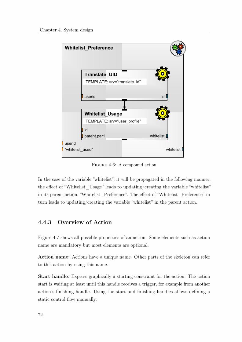
Chapter 4. System design
Whitelist_Preference
useridwhitelist
Whitelist_Usage
idparent.par1
TEMPLATE: srv=“user_profile”
whitelist
Translate_UID
userid
TEMPLATE: srv=“translate_id”
id
“whitelist_used”
Figure 4.6: A compound action
In the case of the variable ”whitelist”, it will be propagated in the following manner;the effect of ”Whitelist_Usage” leads to updating/creating the variable ”whitelist”in its parent action, ”Whitelist_Preference”. The effect of ”Whitelist_Preference” inturn leads to updating/creating the variable ”whitelist” in the parent action.
4.4.3 Overview of Action
Figure 4.7 shows all possible properties of an action. Some elements such as actionname are mandatory but most elements are optional.
Action name: Actions have a unique name. Other parts of the skeleton can referto this action by using this name.
Start handle: Express graphically a starting constraint for the action. The actionstart is waiting at least until this handle receives a trigger, for example from anotheraction’s finishing handle. Using the start and finishing handles allows defining astatic control flow manually.
72

4.4 Service Composition LanguagE
Action_001
var1
START_IF: timer>10
Nested_002
Nested_001
<event handler Binding>
<other definitions>
var2=x+y var4
var3
nested action
action name
local declaration fieldstart handle
USE_IF: usertype=‘premium’
finishing handle
action expressions
input expressions
input handle effect handle
effect variable
action symbol
nested action
Figure 4.7: Action overview
Finishing handle: If the action finishes, this handle provides a trigger. This triggercan be used by means of drawing arrows in order to satisfy start constraints of otherwaiting actions.
Input handle: Input handles are used in order to define dedicated input parametersof the action. If the action is expressing a service template, these input parameterscorrespond to the parameters of the service that is about to be interpreted by thecomposition core.
Effect variable: All variables are local within an action by default. In order topropagate a variable to the parent scope, that variable has to be marked as an effect.
Action expressions: The action expression attributes specific semantics to anaction. That is denoted by a keyword such as:
Template: Service template for query based selection and execution of services.
SELECT: Query based selection of services. Result is a list of services, whichsatisfy the query.
73

Chapter 4. System design
ET1
A3
A1 A2
ET2
A6
A4 A5
11
ET2
A9
A7 A8
&&
Figure 4.8: Execution order
INVOKE: Execute a service. Input is a set of services
DELEGATE: Delegate the execution to another action
SSM: Allows data manipulation such as assigning a value to a variable
CASE: Conditional execution with multiple alternatives
FOREACH: The action is executed for each element in a certain variable. Thisvariable is usually a list. The iterations for each of the variable elements are executedsubsequently
WHILE: Repeat an action as long as a condition is a true
Nested actions: An action can be compound, which means that it contains otheractions. If there are no nested actions the action is atomic. Nested actions areisolated, thus they cannot be referred to outside from their parent.
4.4.4 Execution Order
At runtime, the composition core interprets actions. By default, execution orderis influenced by data dependency. Each action can only be executed once thecorresponding input, required by the action is made available. In the example shownin Figure 4.8, A3 can only be executed once A1’s v1 effect is available. In thesame fashion, actions that do not rely on any input can be executed in parallel. InFigure 4.8, A1, A2, A5 and A6, are such examples.
74

4.4 Service Composition LanguagE
Whitelist_Usage
whitelist
IF: whitelist == 1
Whitelist
Blacklist
ELSELogging
THEN
Figure 4.9: Execution flow
Default execution order can be overridden by using arrows. In such a way, one canenforce a sequential execution paradigm. Such an example is shown in Figure 4.8where an arrow is placed between A1 and A4. This means that A4 can only beexecuted after A1 has finished.
If an action depends on multiple data dependencies originating from other actionscertain expressions can be used in order to determine when the depended actionshould be executed.
• AND: An action will be triggered when all the actions that this action dependson have completed their execution.
• OR: An action will be triggered when at least one of the actions, this actiondepends on has completed it’s execution.
An atomic action is considered to have completed its execution, when its atomicfunction, defined in the action expression has been executed. In the same fashiona compound action is considered to have completed its execution when all of itsnested actions are finished.
75
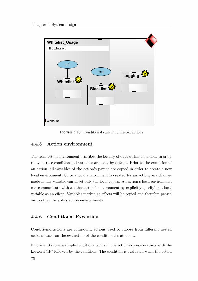
Chapter 4. System design
Whitelist_Usage
whitelist
IF: whitelist
Whitelist
Blacklist
!=1Logging
=1
Figure 4.10: Conditional starting of nested actions
4.4.5 Action environment
The term action environment describes the locality of data within an action. In orderto avoid race conditions all variables are local by default. Prior to the execution ofan action, all variables of the action’s parent are copied in order to create a newlocal environment. Once a local environment is created for an action, any changesmade in any variable can affect only the local copies. An action’s local environmentcan communicate with another action’s environment by explicitly specifying a localvariable as an effect. Variables marked as effects will be copied and therefore passedon to other variable’s action environments.
4.4.6 Conditional Execution
Conditional actions are compound actions used to choose from different nestedactions based on the evaluation of the conditional statement.
Figure 4.10 shows a simple conditional action. The action expression starts with thekeyword ”IF” followed by the condition. The condition is evaluated when the action
76

4.4 Service Composition LanguagE
Message_Sending
preference
IF: preference
Send_SMS
Send_MMS
=‘MMS’
A1
=‘SMS’
Send_Email
=‘EMAIL’
No_Message
ELSE
Message_Selection
message
message
message
message
Logging
Figure 4.11: Alternative conditional starting of nested actions
starts. Labels are used to annotate the different choices that can be made such asTHEN and ELSE. They correspond to the condition being evaluated as true or false.The ELSE label can be optional; if for example the condition evaluates to false andthere is no ELSE label defined, then the action can finish.
In addition, Figure 4.10 contains a nested action called ”Logging”. This action is notconnected anywhere. This means its execution does not depend on the condition. Itis treated as a usual nested action and therefore it will be started in parallel witheither ”WhiteList” Or ”BlackList”.
An alternative usage of the IF type action expression is shown in Figure 4.11. Theconditional expression can be placed on each corresponding label.
Next to an IF statement with two branches it is also possible to use a higher numberof conditional branches. An example is shown in Figure 4.12. The condition is basedon evaluating the variable ”preference”. In this example the conditions distinguish,if the variable ’preferences’ contains the strings ’SMS’, ’MMS’, or ’EMAIL’ in orderto send a notification to a user in the preferred way.
If none of the conditions is fulfilled, the branch marked with ELSE is triggered.The action called ’No’ is always triggered in parallel to the other actions. It is not
77

Chapter 4. System design
Message_Sending
preference
IF: preference
Send_SMS
Send_MMS
=‘MMS’
A1
=‘SMS’
Send_Email
=‘EMAIL’
No_Message
ELSE
Message_Selection
message
message
message
message
Logging
Figure 4.12: High number of conditional branches
part of the conditional triggering but depends on its parent’s start. The action ’A1’is triggered from all three options. In this example, the message sending service’Send_SMS’, ’Send_MMS’ and ’Send_EMAIL’ depend on the actual message textto be available. The text is generated by the service ’Message_selection’. In thisexample, this is modeled by means of a data dependency. The IF condition isevaluated in the beginning of the compound action ’Message_Sending’. The resultof the evaluation triggers the corresponding alternative. Due to the data dependency,the actual start of the triggered message sending service is postponed until theservice ’Message_Selection’ has issued a message text.
The condition expression can also be completely moved to the trigger handlers andit can consist of a complex expression based on multiple variables and complexoperators.
4.4.7 Loops
Loops are created by means of compound actions. The action’s content, includingits nested actions is what is executed at each of the iteration of a loop. Two types ofloops are supported. WHILE loops iterate the compound action while a condition
78
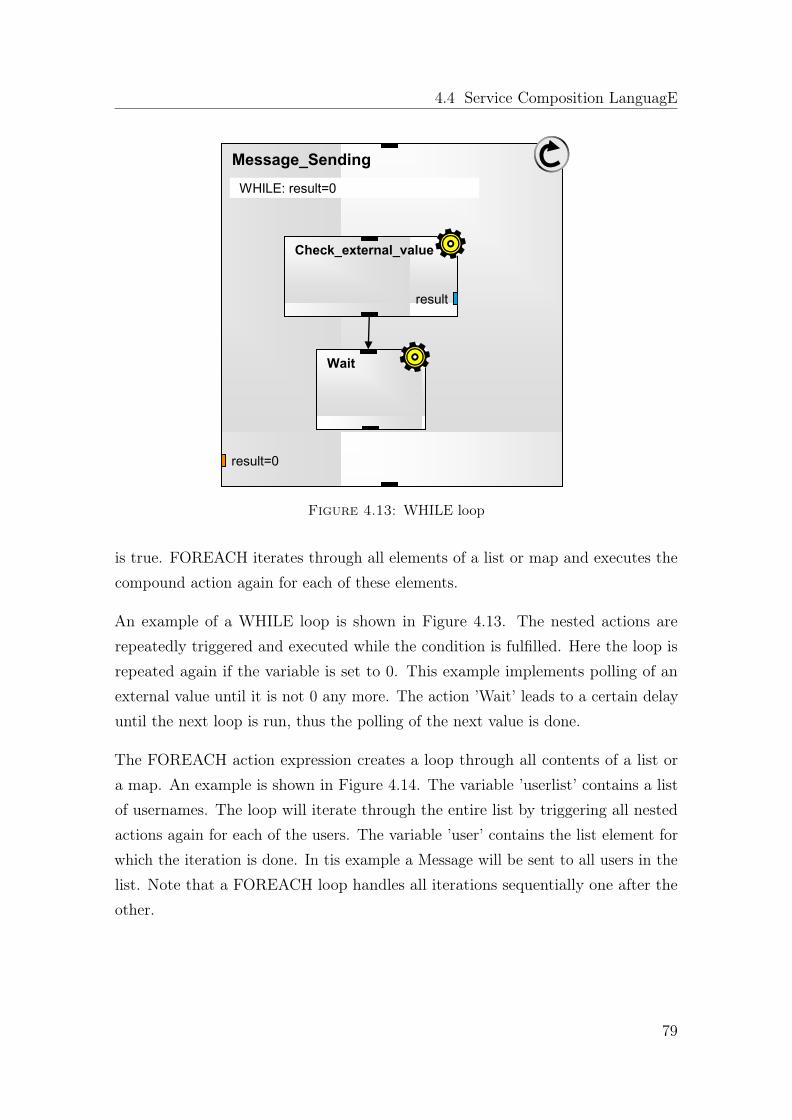
4.4 Service Composition LanguagE
Message_Sending
result=0
WHILE: result=0
Wait
Check_external_value
result
Figure 4.13: WHILE loop
is true. FOREACH iterates through all elements of a list or map and executes thecompound action again for each of these elements.
An example of a WHILE loop is shown in Figure 4.13. The nested actions arerepeatedly triggered and executed while the condition is fulfilled. Here the loop isrepeated again if the variable is set to 0. This example implements polling of anexternal value until it is not 0 any more. The action ’Wait’ leads to a certain delayuntil the next loop is run, thus the polling of the next value is done.
The FOREACH action expression creates a loop through all contents of a list ora map. An example is shown in Figure 4.14. The variable ’userlist’ contains a listof usernames. The loop will iterate through the entire list by triggering all nestedactions again for each of the users. The variable ’user’ contains the list element forwhich the iteration is done. In tis example a Message will be sent to all users in thelist. Note that a FOREACH loop handles all iterations sequentially one after theother.
79
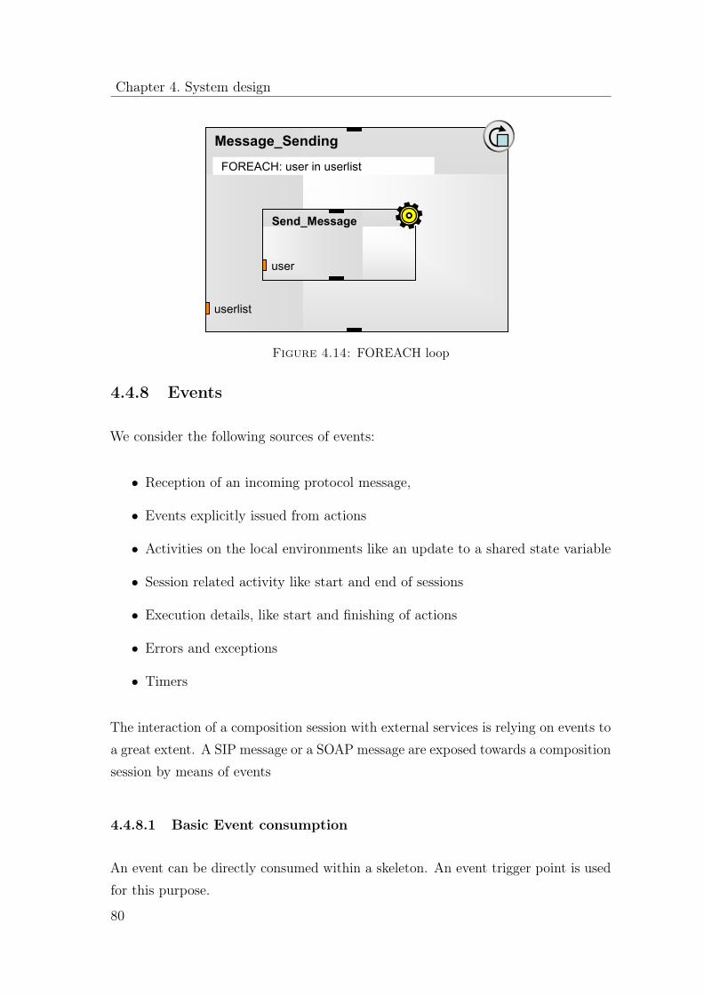
Chapter 4. System design
Message_Sending
userlist
FOREACH: user in userlist
Send_Message
user
Figure 4.14: FOREACH loop
4.4.8 Events
We consider the following sources of events:
• Reception of an incoming protocol message,
• Events explicitly issued from actions
• Activities on the local environments like an update to a shared state variable
• Session related activity like start and end of sessions
• Execution details, like start and finishing of actions
• Errors and exceptions
• Timers
The interaction of a composition session with external services is relying on events toa great extent. A SIP message or a SOAP message are exposed towards a compositionsession by means of events
4.4.8.1 Basic Event consumption
An event can be directly consumed within a skeleton. An event trigger point is usedfor this purpose.
80
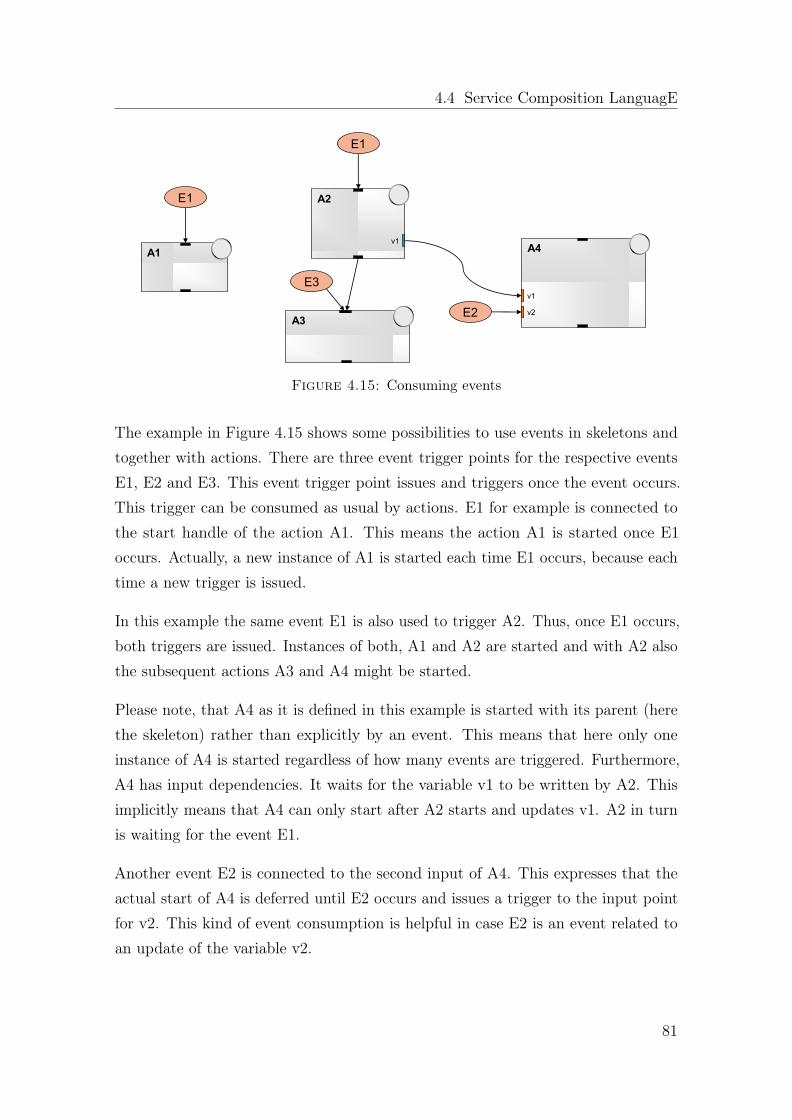
4.4 Service Composition LanguagE
A2
E1
v1A4
v1
A3
A1
v2E2
E1
E3
Figure 4.15: Consuming events
The example in Figure 4.15 shows some possibilities to use events in skeletons andtogether with actions. There are three event trigger points for the respective eventsE1, E2 and E3. This event trigger point issues and triggers once the event occurs.This trigger can be consumed as usual by actions. E1 for example is connected tothe start handle of the action A1. This means the action A1 is started once E1occurs. Actually, a new instance of A1 is started each time E1 occurs, because eachtime a new trigger is issued.
In this example the same event E1 is also used to trigger A2. Thus, once E1 occurs,both triggers are issued. Instances of both, A1 and A2 are started and with A2 alsothe subsequent actions A3 and A4 might be started.
Please note, that A4 as it is defined in this example is started with its parent (herethe skeleton) rather than explicitly by an event. This means that here only oneinstance of A4 is started regardless of how many events are triggered. Furthermore,A4 has input dependencies. It waits for the variable v1 to be written by A2. Thisimplicitly means that A4 can only start after A2 starts and updates v1. A2 in turnis waiting for the event E1.
Another event E2 is connected to the second input of A4. This expresses that theactual start of A4 is deferred until E2 occurs and issues a trigger to the input pointfor v2. This kind of event consumption is helpful in case E2 is an event related toan update of the variable v2.
81

Chapter 4. System design
A2
E4
v1A4
v1
A3
A1
v2
E6
E4
E5
E7v1
Figure 4.16: Issuing explicit events
The event E3 shows, that multiple trigger sources can be used towards a singleaction start handle and that event trigger points can be added to other kinds oftrigger sources.
4.4.8.2 Explicit Event Generation
Events can be issued explicitly from the skeleton elements. Linking triggers to eventsachieve this.
The example in Figure 4.16 shows some of the possibilities to specify explicitly ina skeleton that an event shall be issued. The event E4 is issued once the finishinghandle of A1 or A3 issues a trigger. If A2 is finished, this triggers not only A3through the start handle, but also the event E5 is issued.
If the variable v1 is updated through the effect of A2, also the event E6 is issued.So also for the event generation the data related triggers could be used. This is alsoshown for E7. Once variable v1 is created or updated the event E7 is issued.
Explicit events are therefore all events designed by the skeleton developer.
4.4.8.3 Generation of External Events
Next to explicit events generated directly from skeletons and actions, events issuedby the composition execution engine are of high importance. External protocol
82

4.4 Service Composition LanguagE
messages will be exposed as events towards a composition session. This allowsdesigning dynamic reaction on external activity. This also means that even theinitial external trigger, which caused the composition to start, is exposed as event.
The respective execution agent determines the event name of external events. Policiesof the engine might also be used in order to determine globally which events areissued to composition sessions at all.
4.4.8.4 Generation of System Events
Activities of the composition execution engine are another source of events. Forexample errors and exceptions are exposed like events.
4.4.8.5 Data conveyed in events
Events can have data associated to them. For example the Message parameters of anexternal protocol message are conveyed within events and exposed to the handlingsession as event data.
This data is loaded into the local environment of the event handler when the eventis consumed.
4.4.8.6 Event Locality and Propagation
In order to achieve a controlled event handling it is important to define rules, towhich actions events are issued first and how they are propagated.
SCaLE distinguishes local and non-local events. Local events can clearly be associatedto the local environment of a skeleton or action. It is that environment where theevent was issued from. Explicit events are a good example of a local event, but alsosystem events can be local, if their root cause is within a local environment. Thepropagation rules for local and non-local events are different.
Local events clearly originate in the execution of a particular local action, thus areconsidered to be local to this action’s environment. By default such local eventsare consumed locally and they are not propagated to this action’s parent or even
83

Chapter 4. System design
globally. However, such propagation of the local event can explicitly be initiated.Local events can be propagated to the parent and they can also be issued on globallevel. Exposing and propagating the event to the parent is an effect of the actionand it is also shown as an effect. The event becomes a local event in the parentenvironment. Issuing the event on global level leads to treating it as non-local asdescribed below.
Non-local events are system events and external events that cannot be assigned to aparticular local environment. A policy defined on global skeleton level determineshow a particular non-local event shall be treated and propagated through the skeleton.The default is the following handling: Non-local events are propagated through allactions in a certain order that is derived from the nesting of actions. The generalrule is that non-local events are propagated from inside (lowest nested level) out(global level).
To understand the propagation principle it is important to understand the tree likenature of the action-nesting stack. Action nesting and parallel execution togetherwill lead to multiple nesting stacks in parallel, which are also dynamically changingthroughout the composition execution. As a result the nesting of actions has a treelike structure with the global skeleton level as root of the tree and the lowest nestedlevel as leaves. An example is shown in Figure 4.17. The example shows a skeletonwith nested actions and the respective nesting tree.
If there are multiple nested branches, the propagation of non-local events startsindependently at all leaves. If a non-local event is issued to this composition session,the event is first offered to all these actions, which are the endpoints of the nestingtree.
If a non-local event is issued to an action, which has no event handling defined forit, the event is automatically propagated in the nesting tree branch and issued tothe parent.
If a non-local event is issued to an action and the action consumes it. This eventuallystops the event propagation within the nesting branch of the action. The event isnot automatically propagated unless the action explicitly propagates it to its parent.This means, from an action’s point of view the event handling for local and non-localevents is similar in the respect, which propagation to its parent needs to be explicitly
84

4.4 Service Composition LanguagE
A1 A10
A2
A4
A3
A5
A11
A15
A14
A16
A6
A8
A7
A9
A1
A2
A3
global
A4 A5
A6 A9
A7 A8
A12
A13
A17
A10 A17
A11
A12
A13
A14 A15 A16
Figure 4.17: Action Nesting Stack
initiated. Please note that consuming an event can stop further propagation withinone nesting branch, but does not effect event propagation in other branches of thenesting tree.
At the points where two sub-branches join, the event might be received from bothsub-branches. This means an action can receive the same event instance severaltimes, because it was propagated from several of its nested actions. It is up to theaction to decide if subsequent receptions of the same event instance will also behandled multiple times or ignored.
Event propagation through the entire nesting tree appears to be an enormous andtime-consuming effort if the nesting tree is big. However, it can be expected, thatonly a minority of actions define event handlers for a particular event and only theseactions need to be taken into account. The actual propagation tree for a particularevent is therefore much smaller than the entire nesting tree.
85

Chapter 4. System design
The event propagation policy on global level can deviate from the described defaultevent propagation method. For a certain event it is possible to determine that it isonly issued on global level and not propagated through all nested actions. It is alsopossible to determine that an event is always also issued on global level. This ensuresthat global event handling can consume it even if the event was already consumed byall nested actions. This policy is valid per skeleton, thus the same external event, ifit is issued to several composition sessions might be treated differently from sessionto session.
4.4.8.7 Event handlers
Event handlers are dynamically composed out of actions. This means, an event ishandled by issuing a starting trigger to the starting handle of actions. This triggersaction execution and can cause a number of subsequent actions and nested actionsto also start. Which actions are started in order to execute the event handler isdecided by constraints as usual. The composition engine therefore also composes theevent handler dynamically. Therefore there is usually no clearly unique and distinctentity, which can be called to be the event handler for a particular event. A numberof actions being executed based on a trigger issued, because of an event was received,constitutes the handler.
The event itself is consumed in the skeleton by means of triggers issued throughevent trigger points. If the event occurs several times, for each event a new trigger isissued, which in turn will trigger a new instance of the connected action. Therefore,with each event also a new composition of an event handler is started.
4.4.8.8 Event Filtering / Event Binding
Event binding is a very powerful way to consume and filter events before they arefurther consumed and handled by means of for example trigger senders. This chapteroutlines some of the possibilities.
An event binding is a filter for events. The binding is invoked by the reception ofan event. It contains an expression, which formulates a condition and as result itallows specifying what shall be done. Figure 4.18 illustrates this principle.
86

4.4 Service Composition LanguagE
EVENT Filter / Condition RESULT
Figure 4.18: Event binding
S1 A1
v1
A5
v1
A2
A7
A6
A4
A3
EventBinding EB1: on EVENT1 issue ET1, ET2EventBinding EB2: on EVENT3 while S1=active issue ET2EventBinding EB3: on ET2 issue ET1
EventBinding EB1: on EVENT1 issue ET2 EventBinding EB2: on EVENT2 issue EVENT3
v2
ET1
EVENT3
EVENT2
EVENT3
ET1
ET2 -> EVENT4EVENT2
EVENT1
EVENT3
ET2
EVENT1
A3
EVENT3
EVENT1v2
Figure 4.19: Events and bindings
Event bindings are defined within the action’s local declaration field, thus theevent binding definitions are local. Event bindings are named and can therefore bereferenced for applying changes dynamically.
An event binding can map input events of any type event to an explicit output eventwithin the local environment. This mapping can be conditional, thus the outputevent is only thrown if next to the reception of the input event also a conditionis met. Scopes can be used here. An output event is for example only issued if acertain scope is active.
87

Chapter 4. System design
Figure 4.19 shows some possibilities. The event EVENT1 is consumed directly astrigger for the action A1. Additionally through event binding EB1, EVENT1 ismapped to ET1 and ET2. The event binding EB1 issues ET1 and ET2 each timeEVENT1 occurs.
The event EVENT3 is issued if actions A2 or A3 finish. The eventbinding EB2issues ET2 if EVENT3 occurs while scope S1 is active.
Event handling is by default tied to the local environment. The event EVENT1within the compound action A5 is for example a different event than EVENT1 inthe parent environment.
Within A5 there are some examples of events related to data input and effects.EVENT3 within A5 is for example issued each time a trigger is received related tothe input of variable v1.
EVENT2 within A5 is referring to the event of the same name in the parentenvironment. This means each time EVENT2 occurs in the parent, it also occurswithin A5.
EVENT1 within A5 is triggering the effect related to variable v2. While the defaultbehavior of the effect is to trigger each time the variable is updated, this effect onlytriggers if EVENT1 occurs. This can be used for controlling the effects explicitly.
The second effect of A5 is triggered in case of ET2 occurs. This effect issues EVENT4into the parent environment. This means, that the occurrence of ET2 within A5 isexposed as EVENT4 to the parent.
4.4.9 Data type system
In SCaLE variables can be used without explicit typing and without declarations.Variables are created on demand and composition core selects the type, which isfitting best to the data only when this is required (latent typing). In addition, thecomposition core performs data conversion if the variable is used in a way thatdemands a certain type. For example, the composition core automatically tries toconvert a value into a numeric value once this variable is used within an arithmeticoperation.
88
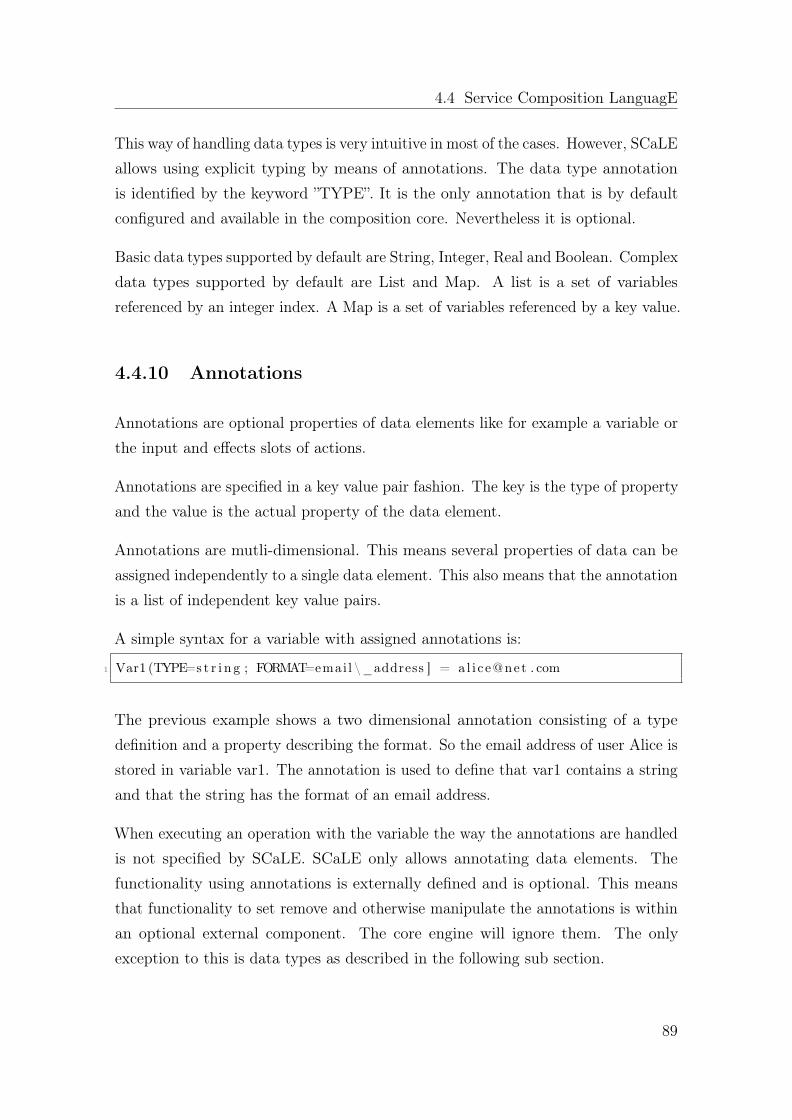
4.4 Service Composition LanguagE
This way of handling data types is very intuitive in most of the cases. However, SCaLEallows using explicit typing by means of annotations. The data type annotationis identified by the keyword ”TYPE”. It is the only annotation that is by defaultconfigured and available in the composition core. Nevertheless it is optional.
Basic data types supported by default are String, Integer, Real and Boolean. Complexdata types supported by default are List and Map. A list is a set of variablesreferenced by an integer index. A Map is a set of variables referenced by a key value.
4.4.10 Annotations
Annotations are optional properties of data elements like for example a variable orthe input and effects slots of actions.
Annotations are specified in a key value pair fashion. The key is the type of propertyand the value is the actual property of the data element.
Annotations are mutli-dimensional. This means several properties of data can beassigned independently to a single data element. This also means that the annotationis a list of independent key value pairs.
A simple syntax for a variable with assigned annotations is:
1 Var1 (TYPE=s t r i n g ; FORMAT=emai l \_address ] = a l i c e@net . com
The previous example shows a two dimensional annotation consisting of a typedefinition and a property describing the format. So the email address of user Alice isstored in variable var1. The annotation is used to define that var1 contains a stringand that the string has the format of an email address.
When executing an operation with the variable the way the annotations are handledis not specified by SCaLE. SCaLE only allows annotating data elements. Thefunctionality using annotations is externally defined and is optional. This meansthat functionality to set remove and otherwise manipulate the annotations is withinan optional external component. The core engine will ignore them. The onlyexception to this is data types as described in the following sub section.
89

Chapter 4. System design
4.4.11 External Type Extensions
Registration of new types and respective handlers for type related operations arepossible through a dedicated API of the SCaLE engine. With a new type alsothe implementation of certain type conversion routines and operates needs to beregistered.
A new type may be needed in order to define data handling that is specific to aservice technology. This is in particular the case if complex data constructs areneeded. Their details might be lost when storing them in variables only relying onthe basic data types of the engine. As these complex types are specific to the servicetechnology, they are defined external of the core engine.
One example where external types may be needed is the storage of a SIP message.It is structured in parameters, which in turn can also have a complex structure.
Another example is SOAP based Web Services. Their data exchange relies on XMLand thus can have a complex structure.
Both examples show technology dependent specific data that shall therefore not beintegrated into the composition core. Having additional types defined in optionalexternal modules means that the stays future proof in two respects; In case a newservice technology evolves, their specific data handling can be added in a modularway. Furthermore, no data type specific to an old service technology stays in thecore engine once this technology is removed thus leaving the system clean of legacy.
4.5 Examples
One of the main design guidelines behind SCaLE is that the underlying technologicaldetails of a service are only instantiated through the process of service binding andinvocation. There are three fundamental ways of interacting with external services:
• Synchronous request-response: A request is sent to the service and the userwaits until a result is delivered
• Asynchronous message exchange: A service is a process, which is executedasynchronously to the client process
90

4.5 Examples
Get_weater_for_locationTEMPLATE: srv=‘get_weather’
Get_location_for_userTEMPLATE: srv=‘get_location’
pos
pos
userid
Get_user_reply_preferenceTEMPLATE: srv=‘get_reply_preference’
userid
weather_forecast
preferred_message
Send_preferred_messageIF: message_preference
userid
text
message_preference
Send_emailTEMPLATE: srv=‘send_email’
text
Send_SMSTEMPLATE: srv=‘send_sms’
userid
=‘mail’
=‘sms’
text
userid
Figure 4.20: Weather information
• Service chaining: The service is a self-contained entity allocated on a messagechain that might ne part of an end-to-end session.
This section provides three examples that detail how the composition core dealswith these distinct interaction patterns with external services. At the end of thissection we provide an additional example that describes a heterogeneous examplethat combines all three interaction patterns.
4.5.1 Synchronous request-response
Re-using external services through a request-response interaction pattern is themost simple example because the interaction between the user and service is basedon a single request being sent to the service and a single response being returned.Re-using SOAP based web services usually follows this pattern. That said, in somecases the return response can be omitted, either because the external service maynot provide one, or because the caller making the request is not interested in theresponse (request-and-forget).
Figure 4.20 shows an example of a simple weather information service based on SOAPthat follows the request-response interaction pattern. The action ”Get_location_for_user”selects and invokes a service that will provide the geographical location of the user.
91
Chapter 4. System design
As the selected service is a web service being consumed in a request-response fashionand synchronously, the action finishes after the location was received as the service’sresponse.
The other service template type actions in this example operate similarly. Theaction ”Get_user_reply_preferences” accesses the user profile in order to determinethe preferred way to send an answer to the user. ”Get_weather_for_location”provides a weather forecast for a specific geographical location. The compoundaction ”Send_prefered_message” is waiting for the message preference informationand the text to be sent, before it decides whether to send an email or a short message.
4.5.2 Asynchronous message exchange
If the goal of the skeleton is to communicate with another independent process,this communication will consist of multiple incoming and outgoing messages thatare asynchronous. Message dispatching will be done through service template typeactions. However, this type of service invocation does not necessarily need to waitfor a response.
Responses will be asynchronously received messages. They are exposed towards thesession as data dependencies. In order to co-ordinate a state machine is modeled.
The example in Figure 4.21 implements a skeleton that subscribes to a stock exchangeinformation system in order to get information of a particular share. It is assumedthat there is a service, which can regularly send updates of the share price. Thisexample subscribes to this service with the share the user is interested in.
4.5.3 Service Chaining
Although the roles and topology when using SIP services differs significantly fromWeb services, SIP services are selected based on queries and service template actions.From the designer’s point of view, first of all it is important to take the decision andselect which service to put on the SIP service chain. This task is mainly guided byselection actions and their corresponding selection queries.
92

4.5 Examples
TERM
Subscribe_share_infoTEMPLATE: srv=‘subscribe_share’’
Get_user_limitTEMPLATE: srv=‘get_limit’
limit
share
userid
Send_preferred_messageIF: pr
pr=price_update.price
limit
userid
Send_emailTEMPLATE: srv=‘send_email’
text=‘limit reached – sell order issued’
Get_Number_of_sharesTEMPLATE: srv=‘sell_shares’
userid
<limit
share
userid
Get_users_shareTEMPLATE: srv=‘get_share’
shareuserid
PU1
Sell_sharesTEMPLATE: srv=‘sell_shares’
userid
share
number_of_shares
subscription_id
number
<limit
EventBinding EB1: on SOAPrequest if XPATH(SOAPrequest.body,“//price_update”).length > 0 issue PU1
EventBinding EB2:on SOAPrequest if XPATH(SOAPrequest.body,”//terminate”).length > 0 issue TERMINATE
TERMINATE
unsubscribe_share_infoTEMPLATE: srv=‘subscribe_share’’
subscription_id
TERMINATE
Figure 4.21: Stock Exchange Monitoring
Once being on the SIP service chain, the service is a self-contained unit takingits own decisions based on the end-to-end signaling it is listening to. Crucial insuch a topology is the order in which services are selected in order to build theservice chain. The second decision of the designer is therefore where the serviceshall be allocated. In practice, within the dynamic process of service chain buildingthis ”Where” decision regarding the service order is actually a ”When” decision.The chain is build successively one service after another. Thus, this part of thedesigner’s decision is subject to queries that are guiding timing and applicationskeleton execution order.
Two or more services without any direct or indirect dependency regarding theirexecution order can be specified in SCaLE. They are considered to be independent ofeach other. If these services are instantiated as SIP services, no clear order for theseservices to be allocated in the SIP service chain can be derived from the applicationskeleton in order to guide the designer. However, SIP service invocations need tobe serialized in order to create an ordered SIP service chain. The composition corewill place SIP services onto the SIP service chain in the order in which they areselected. If there are no ordering constraints, any resulting order, thus any resultingservice sequence on the SIP service chain is possible. This means, if the order in
93

Chapter 4. System design
which the services reside on the SIP service chain matters, additional queries areneeded to express this dependency. It is often the case that the order of services iscrucial in SIP. The same services put into a different sequence will usually result ina significantly different user experience.
The example shown in Figure 4.22 provides a composition consisting of three services.Here explicit ordering is used to express, that the execution order shall be Service1 before Service 2 before Service 3. The composition is triggered by the eventsip_invite, which is bound to the reception of the SIP INVITE method from anIMS network. A SIP INVITE request is a typical first forward message in order toestablish a communication session with a user.
In this example the application skeleton is used in order to compose three servicesat reception of a SIP INVITE. Here, for the purposes of simplicity, all three serviceswill be instantiated as SIP services. A heterogeneous example follows later on insubsection 4.5.4. Figure 4.23 shows a sequence diagram between the users, the IMS,the composition core, and the three SIP services at establishment of the end-to-endSIP session with the two users BOB and ALICE as the endpoints.
On reception of the INVITE message from BOB, the SIP Application Server (SIPAS) contacts the composition core in order to retrieve services to be placed in theend-to-end session. The composition core will trigger the application skeleton shownin Figure 4.22.
According to the application skeleton, the composition core will start building thecomposition by selecting service 1. SIP AS will send the SIP INVITE to the selectedservice 1, where an instance is started. Service 1 returns the SIP invite to the SIPAS and is now logically allocated in the SIP service chain. SIP AS will then ask thecomposition core, if there are more services to consider. The composition core willthen proceed similarly with services 2 and 3.
Please note, that from the point of view of the composition core, the service templateaction for service 1 is not finished before the SIP AS reports about the status of theSIP service execution. Usually this coincides with asking the composition core forthe next service to add. This request for more services might implicitly confirm thatthe previous task of adding a service was done.
94

4.5 Examples
Service 2TEMPLATE: …
Service 1TEMPLATE: …
Service 2TEMPLATE: …
Sip_invite
Leave ContainerCEA_COMMAND: Propagate_Message
Figure 4.22: Skeleton resulting in a SIP service chain
95

Chapter 4. System design
Figure 4.23: Communication sequence including users, SIP services, and com-poser
IMSIMS
BOB ALICEService 1 Service 2 Service 3
Figure 4.24: The resulting SIP service chain
The SIP service chain resulting from this composition is shown in Figure 4.24. Afterall three services were selected a command is given, which will result in indicating toSIP AS that there are no more services to be put on the chain and IMS will routethe SIP invite to the destination in order to conclude the end-to-end session setup.
Please note that the application skeleton does not necessarily finish after instructingSIP AS to proceed with SIP message processing. However, no more SIP servicescan be selected, because the SIP service chain building was finished and dynamicadditions and changes to an already established SIP service chain are not allowed
96

4.5 Examples
according to IMS/SIP standards. The designer has to ensure compliant behavior.Nevertheless other types of services can be used. It would also be possible tocapture further SIP messages within this application skeleton, thus within the samecomposition session.
4.5.3.1 Composition and control of SIP Service Chains
After the initial SIP service chain establishment of the end-to-end communicationsession, messages can be propagated over the SIP service chain both in forward andbackward direction. Usually the services, which reside on the SIP service chain listento the messages when they pass by. The services can autonomously decide if theyignore a message or if they become active. As an example, a service may becomeactive by issuing a message itself or by altering the original message’s content beforeforwarding it.
In addition, the designer may want to participate and take control over the signalingon the SIP session. This means, the composition core needs to be allocated as well inthe SIP service chain to be able to intercept and evaluate signaling. The reception ofa SIP message can be modeled as event reception in the application skeleton. Simplyreceiving an event about the message reception is not sufficient because it is veryimportant to distinguish where on the end-to-end SIP service chain the message wascaught. In order to control which events will be generated execution agents can beconfigured at the initial building of the SIP service chain to stay on the SIP servicechain like services and to generate certain events, which can then be distinguished.
The skeleton in Figure 4.25 shows a complete use case with the SIP services Service1,Service2 and Service3 being put onto the SIP chain. Additionally two executionagent instances are allocated on the SIP service chain at different locations. Theseagents are configured to throw the events E1 or E2 if a message is received at theirrespective location. Two event handler bindings are specified in order to filter outSIP messages of type 486 BUSY and to bind the events to two different handlers.Although the message to be caught is the same, different event handlers are triggereddepending on the location on the SIP chain where the message did appear.
Figure 4.26 shows the SIP service chain that corresponds to the example skeletonfrom Figure 4.25.
97

Chapter 4. System design
Service1TEMPLATE: …
sip_invite
Agent2Command: Throw E2 on message
Service2TEMPLATE: …
Service3TEMPLATE: …
Agent1Command: Throw E1 on message
Propagate_InviteCommand: propagate_message
Action001…
E1_486
EventBinding EB1: on E1 if message_type=486 issue E1_486EventBinding EB2: on E2 if message_type=486 issue E2_486
Propagate_E1
Command: propagate_message
Action002…
E2_486
Propagate_E2
Command: propagate_message
Figure 4.25: Skeleton resulting in SIP service chains with agents for subsequentmessage handling
Service 1 Service 2 Service 3Agent1 Agent2
CompositionEngine
E1 E2
Figure 4.26: The resulting SIP service chain
98

4.5 Examples
The application skeleton can perform a couple of actions. The composition core can,in principle do all a service that resides on the chain is allowed to do. This includesfor example evaluating and modifying the received message before it is propagated.The modifications will be fed back into the SIP chain at the location where theagent did break out with an event. It is also possible to initiate a partial release ofthe SIP service chain and start routing again towards a new destination with newservices. The decision to do so, the control over the exact point where to break thechain and the composition of the new leg can be controlled in detail by means ofskeleton elements.
Although the use of event generating agents was motivated by and demonstrated forSIP service chains, this mechanism is a generic one. It relies on the basic elementsof SCaLE such as events, event handler bindings and actions to provide commandsto the execution agents. These techniques can therefore also be used together withother service technologies. They are not bound to IMS/SIP.
4.5.4 Heterogeneous composition of SIP and Web Services
The examples shown previously have demonstrated how to use SCaLE in order togenerate compositions for a couple of service technologies with different modes ofservice usage, taking into account their special characteristics. A heterogeneouscomposition would go one step ahead and allow composing services from varioustechnologies within a single composition. SCaLE’s main advantage is to permit thiskind of development.
At its core query based service selection is focused on the provided function andagnostic to the technology which implements that desired function. The technologicaldetails will be taken into account only at service invocation rather than at serviceselection.
A simple heterogeneous example that combines web services and SIP services isshown in Figure 4.27. On SIP invite, an action is triggered that retrieves the userpreference with respect to blacklist or whitelist services to be used for the SIP sessions.This service can for example be instantiated with a web service that retrieves thisinformation from a user database. As a result, the preference of the user is storedin a variable. The action Black_or_whitelist evaluates the user preference and
99

Chapter 4. System design
Black_or_whitelistIF: preference
preference
WhitelistTEMPLATE: srv=‘whitelist’
=whitelist
Get_users_preferenceTEMPLATE: srv=‘get_user_preference’
preference
userid
Info = “whitelist_blacklist”
BlacklistTEMPLATE: srv=‘blacklist’
=blacklist
sip_invite
Figure 4.27: Blacklist or whitelist — a simple heterogeneous composition
executes the respectively selected service. As these are SIP services, execution meansthat the respective service is linked into the SIP chain.
4.6 SCaLE and WS-BPEL
This subsection attempts an early-stage use case specific comparison between SCaLEand WS-BPEL. More specifically we illustrate the same use case written in bothlanguages as an early proof of how laconic SCaLE can be when expressing a fully-fledged use case from the telecommunications domain that combines services bothfrom telecommunications but also from the ICT areas.
What is important to highlight here is that this comparison is done simply for thepurposes of motivating in a hands-on manner, what are the benefits of writting inSCaLE as opposed to using WS-BPEL. However, this comparison is by definitionlimited to this particular example and cannot serve as proof for SCaLE’s expres-siveness. For a more complete comparison between SCaLE, WS-BPEL and BPMN2.0 the reader should refer to 6.2 where the expressiveness of all three languages isassessed from a workflow pattern perspective.
The use case chosen for this example is a so-called ”added-value” service, one canimplement over the top in a telecommunications domain. This use case essentiallyallows for notifying a user about a missed phone call, when that user has enabled
100

4.6 SCaLE and WS-BPEL
Name Type Descriptiongoogle_calendar_service REST Retrieves a user’s calendar in XMLReleaseControl SIP Part of SIP Execution Agent - Permits a SIP
request to be released from the ApplicationServer and reach it original destination
user_get_profile WSDL Internal WSDL service used to obtain a user’spermission to access the external calendar
user_get_extid REST Internal REST service used for constructingthe external calendar URI
find_available_slot WSDL Internal Service used for determining nextavailable slot where both parties are available
SendSipResponse SIP Part of SIP Execution Agent - Constructs onthe fly a SIP message that is disseminatedlater on in the IMS network
create_calendar_entry REST Used for submitting an XML snippet thatrepresent a new entry in the Calendar
Table 4.1: Do-not-disturb use case service list
the do-not-disturb feature. The notification is done by means of creating entries in aWeb based calendar. For the purposes of this example we have used Google Calendar.Moreover, this use case allows for rescheduling the phone call at a later point intime, one that is convenient to both parties based on their calendar information.More details on this use case can be found in [169].
The list of external services used by this example is shown in Table 4.1.
Since WS-BPEL does not support interaction with RESTful services, we haveimplemented WSDL based wrappers for all REST based services. Moreover, sinceWS-BPEL does not support Unified routing and therefore does not support the SIPProtocol, we have also created a WSDL based wrapper for our SIP Execution Agent(SIP EA).
We will first implement this use case in SCaLE. The implementation is shown inFigure 4.28
Execution order in SCaLE is by default parallel and asynchronous and it is impliedby data dependencies. The composition framework will execute this applicationskeleton in the following order:
1. Wait for SIP INVITE
101

Chapter 4. System design
Fig
ure
4.28:Do-not-disturb
usecase
inSC
aLE
102

4.6 SCaLE and WS-BPEL
2. Wait for SIP Response
3. Get_callee_calendar
4. Get_callee_next_meeting, Get_caller_calendar
5. Get_caller_agenda, Get_callee_agenda, SIPAgent, SIPAgent
6. find_available_slot, Get_caller_profile, Get_callee_profile
7. log missed call for caller, log missed call for callee, new joint calendar entry
In SCaLE, this example uses two events/event bindings, 3 native commands towardsthe SIP Execution Agent and sends a total of 11 messages to 6 external services.To express this use case as an application skeleton SCaLE requires only 4 uniqueelements - 2 events/event bindings, 3 SIP EA commands, 1 if statement and 11service action templates - therefore a total of 17 elements.
Next we will describe the use case in WS-BPEL using the notation found in OracleFusion Middleware [177], since WS-BPEL is deprived of standardized graphicalnotation. Since the default behavior for executing services in WS-BPEL is linearand synchronous (blocking-calls) we have intentionally tried to implement this usecase in such a way to match the execution order that SCaLE produces by design.As a consequence, the same use case expressed in WS-BPEL is much lengthier dueto the fact that in order to express an asynchronous call towards an external service,WS-BPEL requires at least three elements, one invocation, one wait element (in caseblock waiting is required) and one elmeent for receiving the response. In SCaLEasynchronous invocation is the default behavior. The same use case expressed inWS-BPEL in shown in Figures 4.29 and 4.30.
To express this use case as a workflow in WS-BPEL requires 5 unique elements - 10<receive> elements, 14 <invoke> elements, 4 <wait> elements, 3 <if> elementsand 2 <assign> elements - therefore a total of 33 elements.
The reason why WS-BPEL requires 3 additional invocations to external servicesas opposed to SCaLE is because in SCaLE the interaction with the SIP EA is anative command and therefore is not accounted as an external invocation. Anotherdifference between SCaLE and WS-BPEL is the usage of the <assign> element. InSCaLE assigning values to variable can be done within the action service template
103

Chapter 4. System design
Fig
ure
4.29:Do-not-disturb
usecase
inBPEL,A
-B
104

4.6 SCaLE and WS-BPEL
Fig
ure
4.30
:Do-no
t-disturbusecase
inBPEL,
C-D
105

Chapter 4. System design
element, directly on the input or effect variables, while WS-BPEL requires theusage of an additional element. Finally yet importantly, SCaLE can combine an ifstatement with an event binding, therefore there is no need for an additional elementin order to evaluate a condition.
4.7 Summary
In the beginning of this chapter we have defined our design objectives for theproposed composition framework and the language we coined in order to enable adesigner to compose in a heterogeneous service environment.
We started with the design of the proposed composition framework and its constituentcomponents. These components are the composition core that is responsible forinterpreting SCaLE, the application skeleton repository which is a repository ofapplication skeletons, developed by the various designers using this system, theservices repository which contains a list of service description for external services, alist of pre-existing functionality that can be re-used through queries by an applicationskeleton, a shared state where runtime information is stored, a set of executionagents (HTTP, SIP, WebSockets, IN, ESB)) and last but not least an IntegratedDevelopment Environment which allows for graphical development of compositions.
We then continued our description by detailing the constructs of SCaLE, which isthe language that allows for the definition of compositions as application skeletons.There are three key characteristics in the runtime semantics of the proposed languagethat differentiate it from the state of the art in workflow or workflow like languages.
1. By default, the execution of individual actions, defined in the language isgoverned by data dependencies unless explicit ordering is enforced
2. Instead of strictly typed function calls, queries are used in order to re-usepre-existing functionality which is implemented externally
3. Once a composition is triggered a new session is created that collects all runtimeinformation. Sessions can be re-used for the purposes of data exchange.
4. An optional type system is employed that allows the designer to dynamicallymoved from a dynamic to a static type system.
106

4.7 Summary
We conclude this chapter by providing a set of examples that show how the proposedframework and language can be used to describe services to support either standalone external service interaction patterns, or intertwined permutations of those.Three main interaction patterns are identified: synchronous request-response ( 4.5.1 ),asynchronous message ( 4.5.2 ) exchange and service chaining ( 4.5.3 ). We providedan example for each interaction pattern and finally an example that combines thesepatterns in one ( 4.5.4 ).
Table 4.2 is a reiteration of Table 3.1 from Chapter 3. In this re-iteration we haveadded a column that places our proposed approach in comparison to the approachesfor service composition introduced in Chapter 2.
107

Chapter 4. System design
Static ap-proaches
AI planning DomainSpecificLanguages
SCaLE
Design-time Design to
runtimerelationship
Direct (usescommonlanguageconstructsto definecomposition)
Implicit(planningproblemis trans-formed to acomposition)
Indirect (do-main specificconstructsare relatedto generalpurposeinstructions)
Direct (usescommonlanguageconstructsto define thecomposition)
FormalSemantics
Most cases All cases Most cases Yes
Runtime ob-jects
New objectscan be cre-ated at run-time
All objectsare availablein the initialstate – newobjects arenot toleratedat runtime
New objectscan be cre-ated at run-time
New objectscan be cre-ated at run-time
Service avail-ability
Lack of suit-able servicesin the servicerepositorywould breakthe processat runtime
Lack of suit-able servicesin the servicerepositorybreaks theplanningprocess atdesign-time
Lack of suit-able servicesin the servicerepositorywould breakthe processat runtime
Depends onthe type sys-tem
Run
time Service Invo-
cationLimited to a particular technology Agnostic via
executionagents
Type System Static type system Optionaltype system
Unified rout-ing
Not supported Supported bydesign
Concurrency Explicit definition Implicitly de-fined
Shared State Not supported Supported
Table 4.2: Assessment of approaches to service composition including SCaLE
108

Chapter 5
Implementation
In this chapter we describe the implementation details of the different componentsthat constitute the proposed framework. In a way, the implementation description ofSCaLE can be viewed as an experience report on the usage of the proposed compo-sition framework and the implementation description of the composition frameworkcan be seen as an evaluation of SCaLE usage for practical applications. The imple-mentation was done in order to demonstrate the viability of the proposed approach.This chapter begins by providing an overall description of the implementation ofeach component of the proposed service composition framework. Then we proceedto describe in detail the implementation of each component and most importantly,the implementation of the execution agents.
Moreover, we utilize the explanatory powers of five practical measures of architecturalcomplexity and with the aid of static analysis tools we attempt to evaluate the qualityof the source code base that was developed. The following software metrics [129] areused in order to quantify the size and complexity of this work. More specifically,we measure software lines of code (SLOC), cyclomatic complexity [65], first-orderdensity [103], propagation cost [103] and finally core-size [156].
5.1 Overall description
Our implementation goal is two-fold. On the one hand-side we are interested towardsa highly performant modularly implemented system and on the other hand side
109

Chapter 5. Implementation
we are interested in producing a source code base that is easily understood andmaintained by developers. These particular goals are met by Java and JavaEE,taking into consideration the maturity of this particular language and supportingtool but also the popularity of the language. According to the TIOBE programmingCommunity Index [8], Java ranked as the 1st most popular language in 2008, aposition that was later on taken by C, making Java the 2nd most popular language.
In addition, usage of JavaEE-based SIP application servers has been a common wayto develop applications for the telecommunication domain as early as 2003 withthe introduction of the JSR116 [94] specification, which was later on updated toJSR289 [175] in 2008. The benefits of using a SIP application server (also known asa SIP container) are:
• Usage of a development process that follows a clearly defined and standardizedapproach,
• Usage of the Java programming language (well established programminglanguage with garbage collection and easy to use threading model, controlledby the Java Virtual Machine),
• Re-usability of SIP listeners, controlled by the application server itself.
Essentially, such a setup allows a developer to focus solely on the business logic of aSIP application and on how to handle SIP signaling, instead of worrying about theSIP state machine and how the SIP traffic can reach this application to begin with.As the usage of application servers became more widespread, so did the featuresprovided by them. More specifically, application servers were enhanced to allow forconverged SIP applications that would allow mixing signaling from HTTP with SIPand vice-versa.
5.2 Composition framework
This section reveals the implementation details of the proposed composition frame-work. More specifically, the following components and interaction between them areanalyzed in detail:
110

5.2 Composition framework
• Composition core
• Application skeleton repository
• Services repository
• Shared state
• Execution Agents
HTTP
SIP
As mentioned in Chapter 4, additional components are included in the proposedcomposition framework such as execution agents for WebSockets (Web Sockets EA),Intelligent Networks (IN EA), a JBI Execution Agent for interacting with EnterpriseServices Buses (ESBs) and finally yet importantly an Integrated DevelopmentEnvironment (IDE). Even though these entities have been implemented and arepart of the proposed composition framework, their design and implementationdescriptions is omitted from this thesis. More specifically we focus only on describingthe HTTP and SIP EAs since these two put together, formulate a design complexityspace between a simplistic execution agent (HTTP EA) and a complex one (SIPEA). Therefore all other execution agents, from an implementation complexitypoint of view, would fall somewhere in between and moreover would follow a ratherstreamlined implementation process in order to communicate with the proposedcomposition framework. The design and implementation of an IDE for the proposedlanguage is omitted since we are mostly interested in examining the computationalproperties of the proposed framework and language and not the aspects of the toolthat utilizes them.
5.2.1 Composition Core
Our main design goal is to design a composition core that adheres to an asynchronous,event-driven, non-blocking paradigm.
While JavaEE is a rather mature technology with rich APIs for developing enterprise-grade systems, we have experienced certain limitations when it comes to the im-plementation of highly scalable, asynchronous systems. Specifically, before the
111

Chapter 5. Implementation
introduction of the ”@Asynchronous” annotation in EJB 3.1 [139], all EJB invoca-tions were handled as synchronous, blocking calls, which manifested themselves in athread-per-request style of requests processing. The maximum number of availablethreads (i.e. maximum number of threads in the Java Virtual Machine (JVM) [100]or application server) is a known limiting factor with regards to scalability. Inaddition, this limitation may lead to starvation under very high load or if there aremany long running requests. Alternatively, Message Driven Beans (MDBs) [146]in combination with JMS [80] can better support requirements for asynchrony, buttend to run into similar scalability issues, especially under heavy load as experiencedin typical telecommunication applications.
In the context of our work, applying a thread-per-request model would entail thatdedicated threads handle requests; at least one thread would be responsible forinterpreting an application skeleton until its completion, after which the threadwould be released and made available to other requests. Moreover, invocations ofexternal services would block the thread until a result was available. In such asetup, the amount of composite applications that can be run in parallel is directlyproportional to the amount of available threads. Therefore, the maximum number ofthreads supported by the runtime environment would limit the number of differentapplication skeletons that can be interpreted simultaneously. In the case of JVM,this limit is typically around 15000 or 20000 threads.
This observation motivated us to migrate from a thread-per-request model towardsa mapping of requests to a set of fine-grained executable tasks that can be scheduledon any number of threads. In addition, it led us to make use of non-blocking I/Oapproach for any invocations of services (e.g. SOAP/REST/JBI services), whichavoids blocking the caller thread for the duration of the I/O operation.
Techniques for writing software that operates in non-blocking asynchronous fashionhave been well established in various fields of computer science such as developmentof operating systems [159]. In addition, similar techniques have already beenimplemented in research implementations of BPEL engines such as BPEL-Mora [73]and even into HTTP listener infrastructure such as Grizzly/Comet [105].
The composition core interprets application skeletons by dividing them into smalltasks. Several pools of worker threads that are not tied to a specific applicationskeleton process these tasks. Whenever an application skeleton has to wait for the
112
5.2 Composition framework
execution of an I/O operation, the corresponding task is put on a waiting list andwill be retrieved by a worker thread along with its context information when theresult of the external invocation is available. In addition, some improvements weremade in the area of the support for external protocols such as Grizzly/Comet inHTTP to allow for deferred response notification. These improvements permit thecomposition framework to process a very large number of HTTP or SIP -triggeredapplication skeleton.
Practically speaking for this to be achieved at the source code level, every largeand synchronous method needs to broken down into smaller pieces. The choice offinding at which point a method should be broken into smaller sub-methods wasmade by looking into those segments of code where blocking waiting could occur.Each resulting sub-method is submitted as a task to the thread pool and executessequentially, but when it reaches the break, that is the place where the originalmethod would need to wait for the results of a long-lasting operation or an externalservice invocation, it would register a continuation callback.
The continuation callback creates and submits a task to execute exactly the subse-quent sub-method corresponding to the code of the original method after the break.In addition, it preserves the current state of the application skeleton, starts thelong lasting operation and suspends the execution of current application skeleton byreleasing the thread it currently occupies. In this way, the thread is made availablefor executing other application skeletons. Once the long-lasting operation is over,the registered callback would be triggered, which allows for the application skeletoninterpretation to resume by submitting the next task.
The execution of composite applications is now represented as a set of small tasksexecuted by thread pools. Due to this decoupling from threads, the maximumnumber of threads or the number of threads in the thread pools is not importantany more. Any number of simultaneous application skeletons can be executed evenby a thread-pool with a very small number of threads. This comes at the expense ofconsuming more memory by tasks and the suspended state of application skeletons.Therefore, the amount of available memory for storing this information may become alimiting factor. But even with current commodity hardware such as the one used forour testing purposes, this implementation allows for hundreds of thousands or evenmillions of application skeletons to be handled by one machine, in contrast to 20000
113

Chapter 5. Implementation
composite applications that has been the limitation of a thread-per-compositionapproach.
This style of conversion described here is a well-known transformation called Con-tinuation Passing Style (CPS) [144]. It is often used in functional programming.Functions written in this style never return; instead they always pass what should bedone next (therefore it is called "continuation") as a parameter to the functions theyinvoke. Due to this design, any computation can be easily suspended or resumed atany moment, because continuations contain everything that is required to proceedwith the computation.
Usually, the compiler does CPS transformations automatically. But in the case ofJava-based systems, since Java/JVM does not support continuations, this transfor-mation was done manually and it has been a very difficult task to keep track ofthis conversion. In particular, one should be very careful with providing correctcallbacks, i.e. continuations, and preserving/restoring the state when suspendingand resuming the execution of current composite application.
We had to manually convert all uses of local variables (allocated on the call stack)into uses of variables allocated on the heap and thus surviving thread releases, whencall stack is un-winded by the JVM and information stored on it is lost. Essentially,this part of the transformation was similar to a combination of taking a closure ofcurrent context combined with lambda lifting. Lambda lifting [88] is often used byautomated CPS transformations, where variables from different nested scopes arepromoted into the top-most scope, which would be the heap in this case.
The resulting composition core can be deployed in two ways: inside a JavaEEcontainer (usually the application server SailFin) or standalone. In the lattercase, we provide our own northbound execution agents instead of relying on theinfrastructure provided by the container. This kind deployment reduces the overheadthat is usually added by the application server and allows a more direct managementof threads and resources.
114

5.2 Composition framework
5.2.2 Application skeleton repository
The application skeleton repository is a container for application skeletons (orskeletons). An application skeleton can be understood as a blueprint or patternfor a composite service. The composition core typically uses deployed applicationskeletons, available in the application skeleton repository, as the basis for creatingappropriate composite services. The creation of a composite service based on anapplication skeleton is referred to skeleton execution.
As previously described in 4.4.1 an application skeleton defines:
• The set of participating services
• Structure, i.e. how individual services should connected to composite service,
• Control flow, i.e. in which order individual services should be executed
The designers create application skeletons manually. An application skeleton is staticand cannot be altered by the composition core or by services. Concepts found ingenetic programming [93] are intentionally absent from our proposal for the purposesof ensuring deterministic behavior. However, it is allowed to make execution ofskeleton elements depending on runtime information. So that skeleton elementswill be taken into account during skeleton execution only under certain prerequisiteconditions. Furthermore, skeleton elements can be grouped into branches whoseexecution can be also dependent on runtime information. Examples for possibleruntime information are user preferences, skeleton execution status, network status,allocated resources, etc.
Application skeletons can contain descriptions of alternative services that can beused as replacements for cases where the original service cannot be successfullyexecuted. Alternative services will be executed one-by-one until one of them issuccessfully executed.
These mechanisms make application skeletons more adaptable to runtime context sothat once designed skeleton can be executed repeatedly for a long time period andin different contexts. A consequence of alternative services and elements dependedon runtime information is that different composite services can be derived from one
115

Chapter 5. Implementation
Figure 5.1: Low-level representation of weather information application skeleton
Figure 5.2: Legend for low-level representation symbolism
skeleton. An application skeleton is represented as a directed acyclic graph, as itschematically shown in Figure 5.1.
In practice all the nodes are represented as circles in the underlying system that weuse to store this information. However, in Figure 5.1 we use rectangles to representvariables, circles to represent actions and triangles to represent compound actionsfor the purposes of readability.
An edge originating from a variable and ending in a variable signifies that the actiondepends on that variable while an edge originating from an action and resulting intoa variable means that the action produces that variable.
The representation shown in Figure 5.1 is the actual information that is being storedin the graph database and it has been produced as an example from Figure 5.4. Assuch, the linguistic graphical symbolism presented in the previous section can beviewed as syntactic sugar. This choice was made intentionally in order to simplifythe process of designing the application skeleton.
116

5.2 Composition framework
Figure 5.3: Edge-node, node-edge directed relathionship
Get_weater_for_locationTEMPLATE: srv=‘get_weather’
Get_location_for_userTEMPLATE: srv=‘get_location’
pos
pos
userid
Get_user_reply_preferenceTEMPLATE: srv=‘get_reply_preference’
userid
weather_forecast
preferred_message
Send_preferred_messageIF: message_preference
userid
text
message_preference
Send_emailTEMPLATE: srv=‘send_email’
text
Send_SMSTEMPLATE: srv=‘send_sms’
userid
=‘mail’
=‘sms’
text
userid
Figure 5.4: Weather information application skeleton
Figure 5.5 explains how send_preferred_message is modeled.
5.2.2.1 Graph databases
Graph databases are based on graph theory and as such, they represent informationby using nodes, edges and properties. By definition, a graph database is any storagesystem that provides index-free adjacency. This means that every element containsa direct pointer to its adjacent element and no index lookups are necessary.
We chose to use a graph database instead of a relational database for the purposesof the application skeleton repository since a graph database, offers faster accessto associative data sets and maps more closely to the nature of the applicationskeleton. As such it scales naturally to larges sets of data as it is deprived of join
117

Chapter 5. Implementation
Figure 5.5: Low-level graph representation of weather information applicationskeleton
operations [137]. In addition, it does not depend to a schema and this makes it moreflexible with changing data. In addition, the graph database is a powerful tool forcomputing graph like queries such as computing the shortest path [57].
Several implementations of graph databases exist, Neo4J [118] and OrientDB [123]being the most prominent ones. Angles et al. [6] provide a comprehensive review ofgraph databases. In our case, since we do not want to adhere to a particular graphdatabase, we chose to use blueprints by Tinkerpop [138] that allows for agnosticaccess to any graph database that supports the blueprints generic graph API. For thepurposes of the prototype development we chose to use Neo4J along with blueprintsdue to the maturity of that particular graph database implementation and the largecommunity around it.
5.2.2.2 Service template action
A service template action is a placeholder for one specific service, more precisely fora reference to one specific service. This service will be selected at runtime from thelist of compatible services that will be created based on the information provided bythe service template. A list of compatible services can be defined in two ways:
118
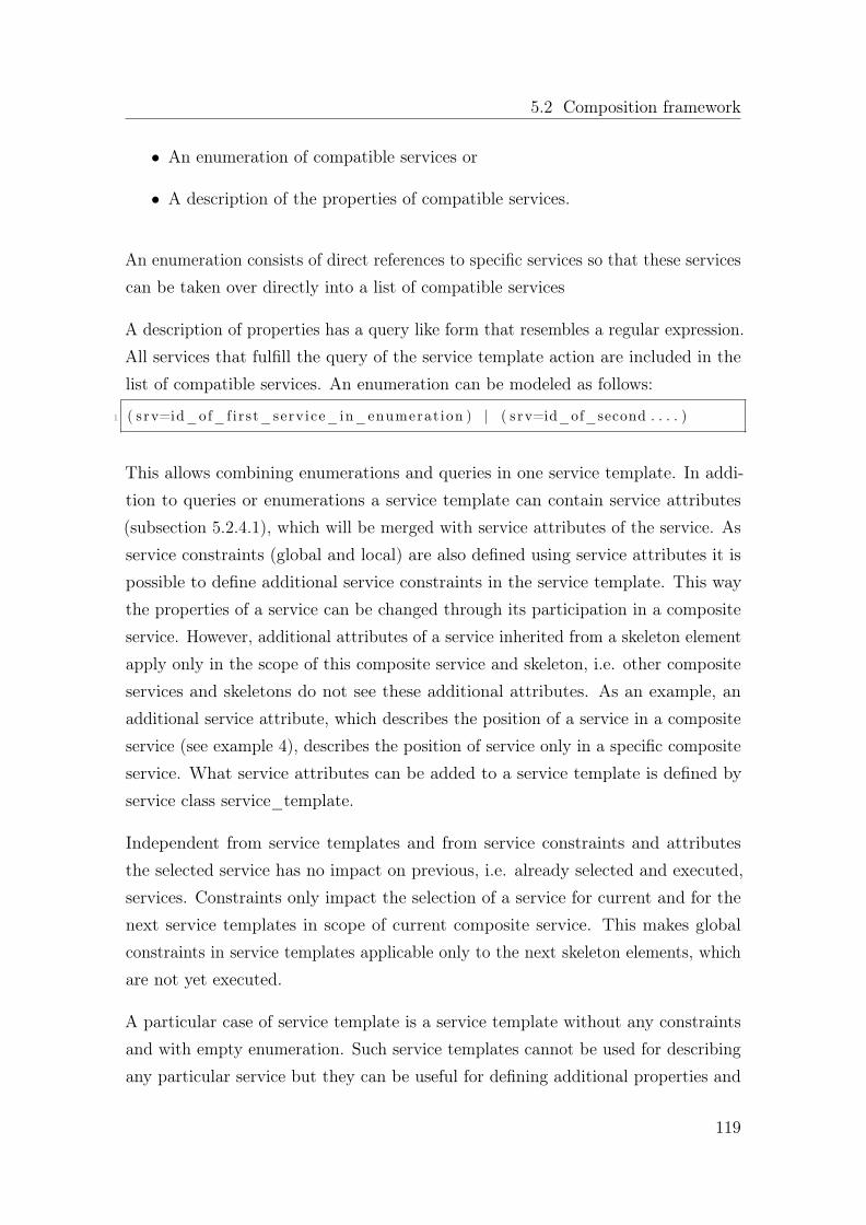
5.2 Composition framework
• An enumeration of compatible services or
• A description of the properties of compatible services.
An enumeration consists of direct references to specific services so that these servicescan be taken over directly into a list of compatible services
A description of properties has a query like form that resembles a regular expression.All services that fulfill the query of the service template action are included in thelist of compatible services. An enumeration can be modeled as follows:
1 ( s rv=id_of_f irst_service_in_enumerat ion ) | ( s rv=id_of_second . . . . )
This allows combining enumerations and queries in one service template. In addi-tion to queries or enumerations a service template can contain service attributes(subsection 5.2.4.1), which will be merged with service attributes of the service. Asservice constraints (global and local) are also defined using service attributes it ispossible to define additional service constraints in the service template. This waythe properties of a service can be changed through its participation in a compositeservice. However, additional attributes of a service inherited from a skeleton elementapply only in the scope of this composite service and skeleton, i.e. other compositeservices and skeletons do not see these additional attributes. As an example, anadditional service attribute, which describes the position of a service in a compositeservice (see example 4), describes the position of service only in a specific compositeservice. What service attributes can be added to a service template is defined byservice class service_template.
Independent from service templates and from service constraints and attributesthe selected service has no impact on previous, i.e. already selected and executed,services. Constraints only impact the selection of a service for current and for thenext service templates in scope of current composite service. This makes globalconstraints in service templates applicable only to the next skeleton elements, whichare not yet executed.
A particular case of service template is a service template without any constraintsand with empty enumeration. Such service templates cannot be used for describingany particular service but they can be useful for defining additional properties and
119

Chapter 5. Implementation
limitations for a composite service, e.g. global constraints can be defined in suchservice templates.
The following examples (1-6) illustrate the use of service templates in Polish prefixnotation [60].
1. enumeration
1 [ serv iceA , serv iceB , serv iceC , se rv i ceD ]
list of compatible services: serviceA, serviceB, serviceC, serviceD
2. with a constraint
1 [ (&( | ( s e rv i c e_prov ide r=providerA ) ( s e rv i c e_prov ide r=providerB ) ) (func t i on=VoIP) ) ]
list of compatible services: all services from providerA and providerB withVoIP functionality.
3. with enumeration and a constraint:
1 [ | ( s rv=serv i ceA ) ( s rv=s e r v i c e ) ( func t i on=VoIP) )
list of compatible services: serviceA and serviceB and all services with VoIPfunctionality.
4. with additional attributes
1 ( | ( s rv=serv i ceA ) ( srv=s e r v i c e ) ( func t i on=VoIP) )serv ice_pos i t ion_in_compos i t ion : 3
list of compatible services: the additional service attribute describes the positionof the service in the composite service. The service that will participate in thecomposite service gets this additional attribute from a service template
5. with additional constraints
1 ( | ( s rv=serv i ceA ) ( srv=s e r v i c e ) ( func t i on=VoIP) ) g l oba l_cons t ra in t :( prov ide r=providerA ) c on s t r a i n t : ( f unc t i on=wh i t e_ l i s t )
list of compatible services: The additional constraint permits the combinationof the selected service with the services with function white_list and enforcesthat all services in the composite service belong to providerA.
120

5.2 Composition framework
6. Skeleton objects
1 [ g l oba l \ _constra int : ( prov ide r=providerA ) ]
list of compatible services: All following services must belongs to providerA
In most cases the results of the evaluation of the service templates is the executionof at least one service so that a service element has impact outside composition core.In contrast, the element described in the next chapter only has impact inside thecomposition core.
5.2.2.3 Parameter passing in service action templates
This subsection details the inner-workings of the process of passing input parametersto external services when using service action templates. Essentially, this processattempts to solve the problem of associating input parameters to selected servicesto be invoked.
Assume that the result of dynamic service selection, implemented by means of aservice template action has returned three different results for a certain query.
• Result 1: foo(XMLDocument1 doc1)
• Result 2: foo(JSONDocument1 doc2)
• Result 3: foo(CustomPayload doc3)]
This implies that three different services are applicable to a particular query. Unlikenormal programming languages, where function invocation needs to deal with placingeach input to a particular argument placeholder, in our case, since we deal withexternal services we need to take care of placing the designer’s input parameter tothe correct placeholders within different kinds of payloads, such XML, JavaScriptObject Notation (JSON) and custom user made payloads. Placing placeholders ineach document, in the particular points where designer’s input needs to be placed,does this.
Consider listing 5.1 as part of XMLDocument1:
121

Chapter 5. Implementation
1 <note><to>${ to }</ to>
3 <from>${ from}</from><heading>${ heading }</heading>
5 <body>${body}</body></note>
Listing 5.1: Annotated XML Snippet
In this snippet you will notice four distinct placeholders marked with ${ and }. Byplacing these placeholders, the composition core knows at runtime where to put thecontents for runtime variables to, from, heading and body.
The same principle applies to JSONDocument1 in listing 5.2
{2 " employees " : [
{ " f i rstName " :" ${employeeName1}" , " lastName " :" ${employeeLastName1}"} ,
4 { " f i rstName " :" ${employeeName2}" , " lastName " : " " : " ${employeeLastName1}" } ,
{ " f i rstName " :" ${employeeName3}" , " lastName " : " " : " ${employeeLastName1}" }
6 ]}
Listing 5.2: Annotated JSON Snippet
Placeholder information is set in the service description for reach external service.
5.2.2.4 Conditional elements
A skeleton condition is an expression that will be evaluated at runtime using runtimeinformation. Depending on the evaluation results a skeleton branch will be selected.Thus providing conditional elements with better control over skeleton execution andallowing the creation of composite services depending on runtime variables.
The composition core provides a set of runtime variables that can be used to evaluateconditional statements. Such information includes the original request, the userprofile, the participating devices, the current status of skeleton execution and the
122

5.2 Composition framework
Operands / Re-sult Type
Logical Numerical Textual
Logical OR, AND, NOT, XOR =, <, > =, containNumerical +, -, * length, positionTextual upper_case, sub_string
Table 5.1: Operations applicable to runtime variables
composite service. Runtime variables can have logical, numerical or textual values.The usage of runtime variables is described in detail in subsection 5.2.3.1. Theoperations in Table 5.1 can be used with runtime variables depending on their values.
In addition to these operations the usage of parentheses in conditional expressions isallowed. The invocation of services from conditional expressions is not allowed.
The value of runtime variables cannot be changed directly by skeleton elements.However, the execution of skeleton elements may result in the modification ofinformation regarding the skeleton execution, e.g. the currently processed element,execution results, etc. Skeleton elements may therefore have indirect impact onruntime variables. Furthermore, individual services can create new and changeexisting runtime variables. This way services can influence indirectly the creation ofa composite service.
For each possible result of a conditional expression a skeleton branch must be defined.The definition of a default branch is allowed. If no branch corresponds to the resultof the conditional expression, the skeleton execution is terminated.
The following (1-3) examples illustrate alternatives for conditional expressions:
1. A logical condition with the runtime variable request type, which is TRUE ifthe original request was a SIP request.
123
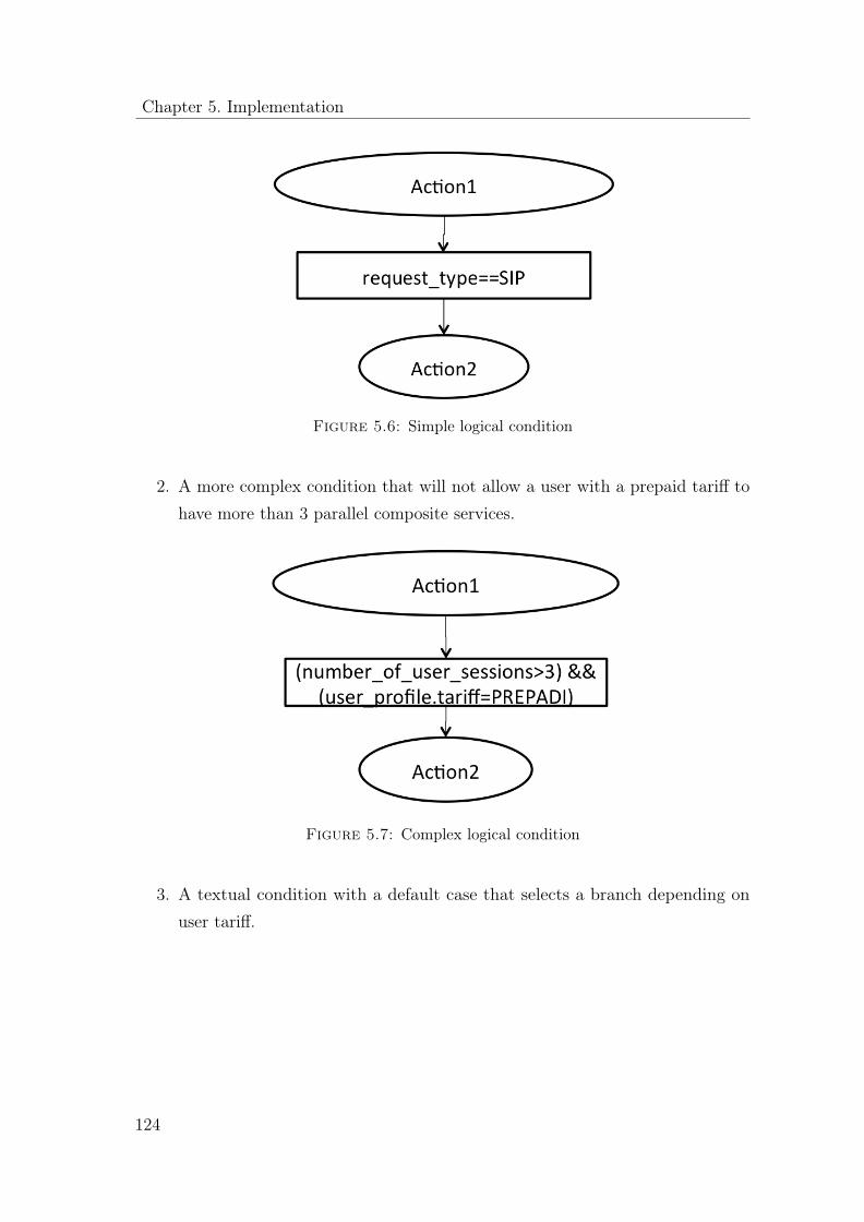
Chapter 5. Implementation
Figure 5.6: Simple logical condition
2. A more complex condition that will not allow a user with a prepaid tariff tohave more than 3 parallel composite services.
Figure 5.7: Complex logical condition
3. A textual condition with a default case that selects a branch depending onuser tariff.
124
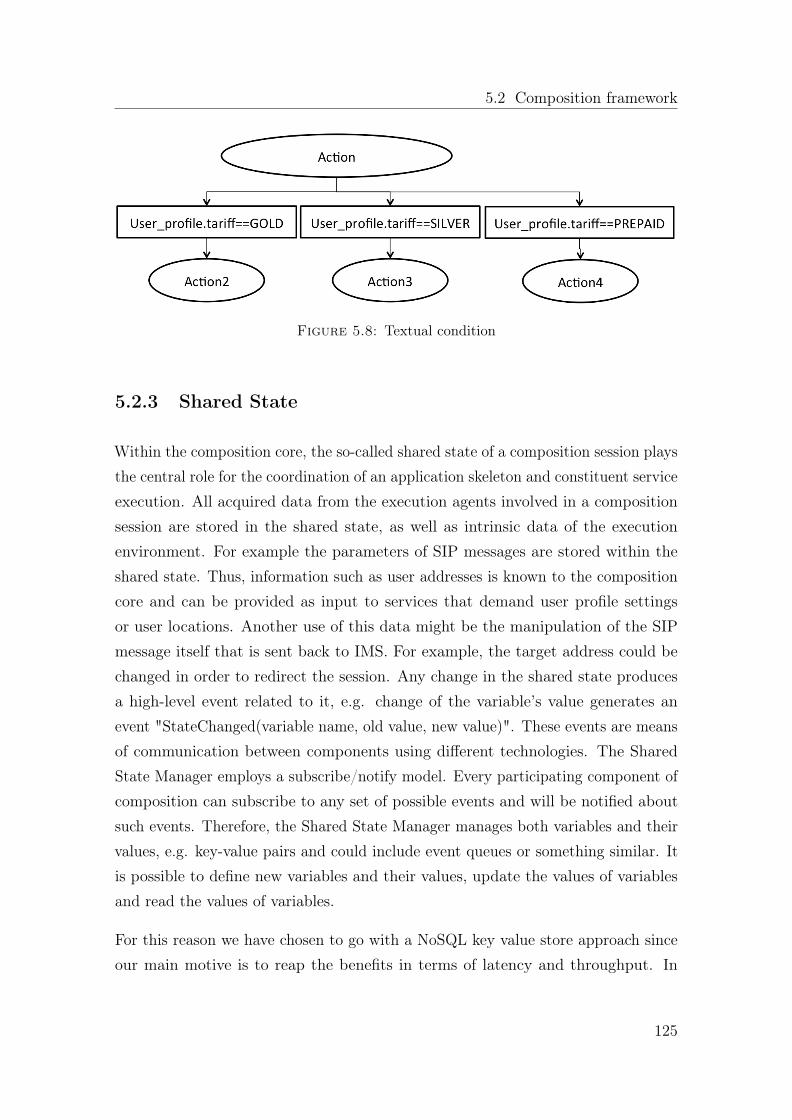
5.2 Composition framework
Figure 5.8: Textual condition
5.2.3 Shared State
Within the composition core, the so-called shared state of a composition session playsthe central role for the coordination of an application skeleton and constituent serviceexecution. All acquired data from the execution agents involved in a compositionsession are stored in the shared state, as well as intrinsic data of the executionenvironment. For example the parameters of SIP messages are stored within theshared state. Thus, information such as user addresses is known to the compositioncore and can be provided as input to services that demand user profile settingsor user locations. Another use of this data might be the manipulation of the SIPmessage itself that is sent back to IMS. For example, the target address could bechanged in order to redirect the session. Any change in the shared state producesa high-level event related to it, e.g. change of the variable’s value generates anevent "StateChanged(variable name, old value, new value)". These events are meansof communication between components using different technologies. The SharedState Manager employs a subscribe/notify model. Every participating component ofcomposition can subscribe to any set of possible events and will be notified aboutsuch events. Therefore, the Shared State Manager manages both variables and theirvalues, e.g. key-value pairs and could include event queues or something similar. Itis possible to define new variables and their values, update the values of variablesand read the values of variables.
For this reason we have chosen to go with a NoSQL key value store approach sinceour main motive is to reap the benefits in terms of latency and throughput. In
125

Chapter 5. Implementation
particular we chose to use Apache Cassandra [95], which is actually a hybrid betweena key value store and a row-oriented database.
5.2.3.1 Session Information
The information available in the shared state manager is grouped per session and itis referred to as Session Information. This information is created at runtime andconsists of a set of variables that keep track of the current state of the applicationskeleton. These variables are referred to as runtime variables. Session informationis by default private to the application skeleton that handles the request thatresulted into the creation of the session to begin with. However, there is a specialsession called global whose information can be accessed by any other session. Anidentifier of a variable in a global session always stars with the prefix ”global”, i.e.global.user_session_count. Table 5.2 provides an example of session informationvariables that are created by default for every application skeleton instantiation.The purpose of such variables is to keep track of a skeleton’s execution state.
126

5.2 Composition frameworkVariableid
Variable
Typ
eDescription
Exa
mple
skeleton
String
IDof
initialS
keleton
voipSk
eleton
skeleton
.last_elem
ent
String
IDof
last
evalua
tedskeleton
elem
ent
busy_check
skeleton
.last_elem
ent.skeleton
_id
String
IDof
skeleton
oflast
evalua
tedskeleton
elem
ent
voipSk
eleton
skeleton
.last_elem
ent.type
String
Typ
eof
last
evalua
tedskeleton
elem
ent
SERV
ICE
TEMPLA
TE
skeleton
.last_elem
ent.result
String
Resultof
last
evalua
tion
(uriof
service
orcond
itionresult)
sip@
server.com
skeleton
.next_
elem
ent
String
IDof
thenext
tobe
evalua
tedelem
ent
ofskeleton
checkU
serP
rofile
skeleton
.next_
elem
ent.type
String
Typ
eof
thenext
tobe
evalua
tedele-
mentof
skeleton
CONDIT
ION
skeleton
.executed_
elem
ents_coun
tint
Cou
ntof
executed
skeleton
elem
ents
3skeleton
.executed_
elem
ent1
String
Idof
first
executed
skeleton
elem
ent
skeleton
1skeleton
.executed_
elem
ent1.skeleton_
idString
IDof
Skeleton
ofthefirst
elem
ent
voipSk
eleton
skeleton
.executed_
elem
ent1.ty
peString
Typ
eof
thefirst
executed
elem
ent
START
skeleton
.executed_
elem
ent1.result
String
Resulto
fevaluationof
thefirst
executed
elem
ent
skeleton
.executed_
elem
ent2
String
Second
executed
skeleton
elem
ent
busy_check_
wl
skeleton
.executed_
elem
ent2.skeletonId
String
IDof
Skeleton
ofthesecond
elem
ent
voipSk
eleton
skeleton
.executed_
elem
ent2.ty
peString
Typ
eof
thesecond
executed
elem
ent
SERV
ICE
TEMPLA
TE
skeleton
.executed_
elem
ent2.result
String
Resultof
evalua
tion
ofthesecond
exe-
cutedelem
ent
busy_check_
wl@
server1.com
user_profi
leString
internal
IDof
user
profi
lebo
b_profi
leuser_profi
le.user_
type
String
Typ
eof
user
e.g.
norm
al,g
old,
etc
norm
aluser_profi
le.preferred_au
dio_
service
String
Preferred
audioservicee.g.
voip,ptt,
etc
ptt
Tabl
e5.
2:Defau
ltruntim
evariab
les
127

Chapter 5. Implementation
Moreover, external services and applications can define additional runtime variablesand provide on this way their runtime information to the composition core and tocomposite services. Further it is conceivable that services (e.g. Voice Over IP (VoIP)server) can provide information about its status using an interface to these objects(e.g. the VoIP object) and the skeleton can include conditions, in which this statuswill be evaluated. An external runtime variable is independent from the compositeservice and is identical in all runtime environments. The external runtime objectsallow better integration of external services into composition process. However, theskeleton designer must know these external services and their objects. Runtimevariables are referenced from a skeleton and service descriptions using this form:
1 ${ o b j e c t_ i d e n t i f i e r . v a r i a b l e_ i d e n t i f i e r }
Example:
1 ${ u s e r_pro f i l e . t a r i f f }${ sk e l e t on . last_element . r e s u l t }
5.2.4 Services repository
An important aspect in the overall process of service composition is the availabilityof a repository of service descriptions that describe the characteristics of externalservices that can be re-used. More specifically a service description contains informa-tion that is useful for an execution agent, with regards to how to access an externalservice and information regarding the properties of an external service that is usefulfor the designer.
The composition core has access to information on the requirements of all servicesinvolved as well as the functionality they are in a position to provide to otherservices. Since the internal functionally of a service is hidden from the compositioncore and the information that can be extracted from established service descriptions,e.g. SDP [79] or WSDL, is not enough for the overall composition on a functionallevel, additional information about service properties is needed. This information ismodeled using service attributes and service constraints. Service attributes describewhat a service provides and service constraints describe what a service requires.These two modeling mechanisms are discussed in the 5.2.4.1 and 5.2.4.2 respectively.
128

5.2 Composition framework
srv ServiceAURI sip://server.com/voipservice_provider ProviderAfunction audio_transmitionaudio_codec GSMaudio_codec G.771description VoIP service
Table 5.3: Service description - example 1
srv ServiceBURI sip://server.com/chargingservice_provider ProviderBfunction audio_transmitioncharging_tariff VoIPcharging_standard CAPv3description Charging service for VoIP
Table 5.4: Service description - example 2
5.2.4.1 Service attributes
Service properties are described as a set of service attributes. A service attributeconsists of an attribute identifier and an attribute value. Attributes of a servicecan be interpreted in terms of resource-based reasoning as resources or functionalityprovided by a service. For example, an attribute with identifier ”codec” and value”G.711” can be interpreted to mean that the service described by this attributeprovides the functionality of a G.771 codec. Each service description contains aunique identifier, e.g. an attribute srv that contains a value used to uniquely identifythe service. In addition, service attributes can be also used for describing generalservice properties such a human-readable description, the URI of a service, etc.
For the textual representation of service attributes, the LDAP Data InterchangeFormat (LDIF), described in RFC 2849, is used in this document. LDIF is a widelyaccepted format for textual data representation and is used by LDAP directories formanaging service information.
Table 5.3 and 5.4 are hypothetical examples of service descriptions for a VoIP and acharging service. According to LDIF syntax an attribute identifier is separated fromits attribute value by a colon ”:”.
129
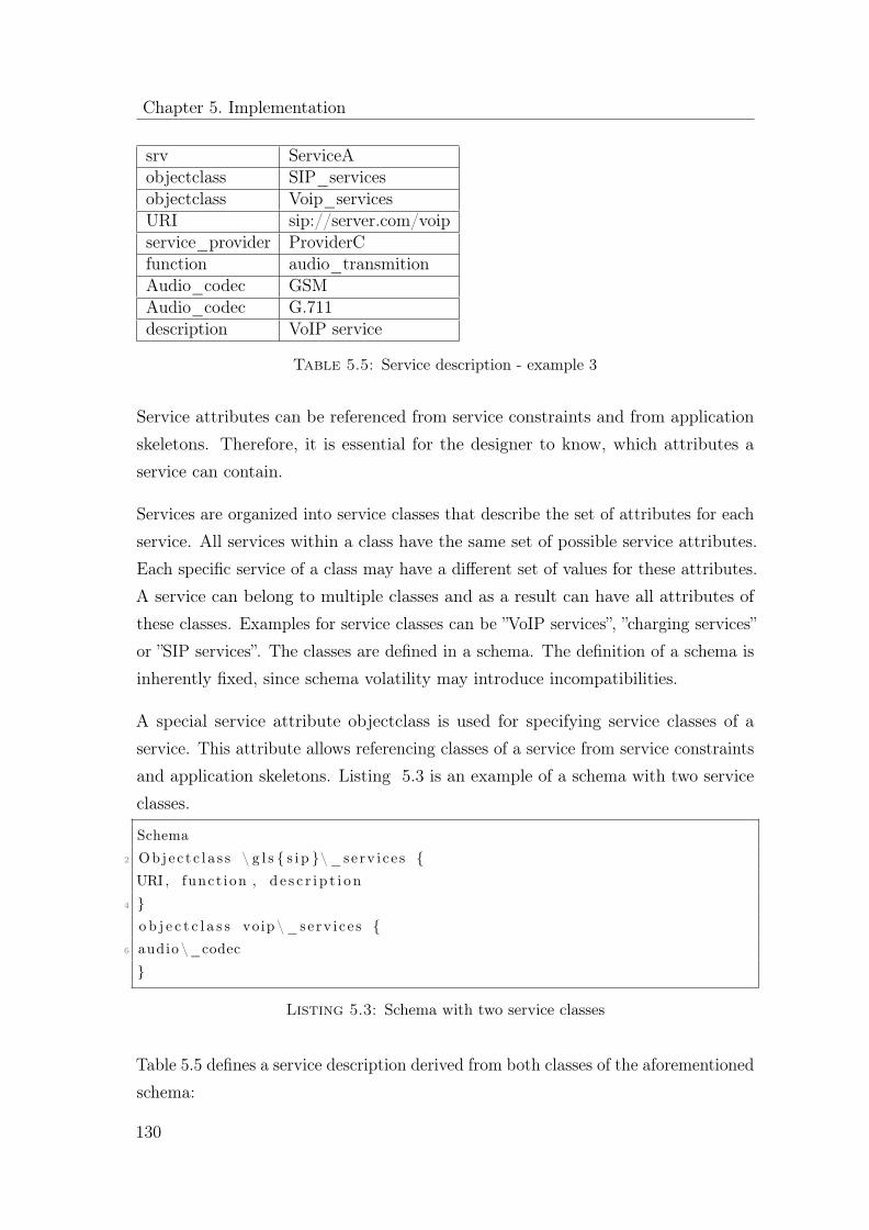
Chapter 5. Implementation
srv ServiceAobjectclass SIP_servicesobjectclass Voip_servicesURI sip://server.com/voipservice_provider ProviderCfunction audio_transmitionAudio_codec GSMAudio_codec G.711description VoIP service
Table 5.5: Service description - example 3
Service attributes can be referenced from service constraints and from applicationskeletons. Therefore, it is essential for the designer to know, which attributes aservice can contain.
Services are organized into service classes that describe the set of attributes for eachservice. All services within a class have the same set of possible service attributes.Each specific service of a class may have a different set of values for these attributes.A service can belong to multiple classes and as a result can have all attributes ofthese classes. Examples for service classes can be ”VoIP services”, ”charging services”or ”SIP services”. The classes are defined in a schema. The definition of a schema isinherently fixed, since schema volatility may introduce incompatibilities.
A special service attribute objectclass is used for specifying service classes of aservice. This attribute allows referencing classes of a service from service constraintsand application skeletons. Listing 5.3 is an example of a schema with two serviceclasses.
Schema2 Obje c t c l a s s \ g l s { s i p }\ _serv i c e s {
URI , funct ion , d e s c r i p t i o n4 }
o b j e c t c l a s s voip \ _serv i c e s {6 audio \_codec
}
Listing 5.3: Schema with two service classes
Table 5.5 defines a service description derived from both classes of the aforementionedschema:
130

5.2 Composition framework
5.2.4.2 Service constraints
Pre-conditions and post-conditions of a service can be defined via service constraints.Service constraints can be interpreted in terms of resource-based reasoning as re-sources that are consumed by a service. A service constraint is a logical expressionthat is formulated by referencing service attributes. The usage of logical, mathe-matical, string operations and parentheses is allowed in constraints. For the textualrepresentation of service constraints the LDAP Filter format as described in RFC2254 is used. Listing 5.4 illustrates a service constraint describing the necessity of acharging resource with the charging standard VoIP is required.
1 (&( func t i on = charg ing ) ( cha r g i n g_ta r i f f = VoIP) )
Listing 5.4: Service constraint example 1
In this example, function and charging_tariff are attribute identifiers and chargingand VoIP are required attribute values. This constraint is valid only if a servicedescription exists that accommodates these two requested attribute values. Forinstance the VoIP service described in the examples in subsection 5.2.4.1 fulfills thisconstraint.
Instead of service attributes runtime variables can also be referenced in constraints.Runtime variables were discussed in detail in subsection 5.2.3.1. Listing 5.5 containsa constraint that uses a runtime variable to indicate that this particular servicecannot be the first service to be executed in a composition.
1 ( s k e l e t on . executed_elements_count >1)
Listing 5.5: Service constraint example 2
Constraints are grouped into global and local constraints. A global constraint mustbe valid in the context of a composite service, i.e. each service in a compositeservice must fulfill the global constraints. Global constraints are useful for definingrestrictions applicable to all components of the composite service, e.g. all servicesin a composite service must be from the same provider or all services must be SIPservices.
A local constraint must be valid in the context of the neighboring components ofthe service, i.e. services connected to the service with the local constraint must
131

Chapter 5. Implementation
srv ServiceAobjectclass SIP_servicesobjectclass Voip_servicesURI sip://server.com/voipservice_provider ProviderCfunction audio_transmitionAudio_codec GSMAudio_codec G.711description VoIP serviceconstraint ($(function=charging)(tariff=VoIP)(provider=providerC))
Table 5.6: Service description with local constraint - example 4
fulfill this constraint. In contrast to global constraints it is not necessary that allneighboring services fulfill the local constraint. In this case it suffices if at least oneneighboring service fulfills it. Consequently a service describes what services it iscompatible with through its local constraints.
Constraints are part of the service description and will be defined using specialservice attributes: a global constraint through service attribute global_constraintand a local constraint through constraint service attribute. Table 5.6 is an exampleof a VoIP services that requires a charging service from same provider as VoIP andwith the charging tariff VoIP:
Figure 5.9 illustrates the impact areas of local and global constraints.
Multiple global_constraint attributes in a single service description are joined with aBoolean AND ”&” into one global constraint. In contrast multiple constraint serviceattributes are not connected and will be considered as two independent constraints.It is therefore possible that one local constraint will be satisfied by one service andanother local constraint by another service.
Table 5.7 illustrates a service requiring that at least one of its neighboring servicesshould provide the function charging for tariff VoIP and least one of its neighboringservices should belong to providerA. However these constraints can be fulfilled bytwo different services.
Table 5.8 is an example of a service with a global constraint that forces all servicesin the composite service to be SIP services offered by providerA.
132

5.2 Composition framework
Figure 5.9: Local vs global constraints
srv ServiceAobjectclass SIP_servicesobjectclass Voip_servicesURI sip://server.com/voipservice_provider ProviderAfunction audio_transmitionAudio_codec GSMAudio_codec G.711description VoIP serviceconstraint (&(function=charging)(tariff=VoIP))constraint (provider=providerA)
Table 5.7: Service description with local constraint - example 5
133

Chapter 5. Implementation
srv ServiceAobjectclass SIP_servicesobjectclass Voip_servicesURI sip://server.com/voipservice_provider ProviderCfunction audio_transmitionAudio_codec GSMAudio_codec G.711description VoIP serviceconstraint (&(function=charging)(tariff=VoIP))global_constraint (&(service_class=sip_services)(provider=providerA))
Table 5.8: Service description with local and global constraint - example 6
From a complexity theory point of view constraint resolution is defined as a satisfi-abillity problem whose instance is a Boolean expression written using only AND,OR, NOT, variables and parenthesis. Boolean satisfiability problem are interestingbecause it is an NP-Complete problem and therefore incorporating this feature intoour system, does not yield to poor performance as we examine later on in the chapter6 where we evaluate our prototype work.
5.2.5 Execution Agents
This section describes the implementation details of two execution agents, the SIPExecution Agent and the HTTP Execution Agent. We will begin our descriptionwith the SIP Execution Agent since its implementation is far from trivial.
5.2.5.1 SIP Execution Agent
This subsection describes the implementation of the SIP EA and presents one exampleuse case with signaling flow. The basic routing mechanisms include routing in theSIP/IP core S-CSCF, e.g. triggering of messages to JSR116 containers. Furthermore,for the purposes of invoking SIP servlets, routing/dispatching takes place withinthe container. As always, reducing signaling across different network elements isdesirable. With that in mind, the working assumption is that most routing takesplace on top of the container/dispatcher, where most enabling services are invokedand potentially also the communication service (e.g. chat). This is achieved by
134

5.2 Composition framework
keeping most signaling within the application server (AS), i.e. either via the JSR116dispatcher or internal in the servlets. This reduces the involvement of the S-CSCFand the less signaling towards the S-CSCF, the better.
Routing outside of the container e.g. to address a communication service deployedon a different AS is performed under the assumption that the request will terminateoutside the initial AS. In case the request leaves the original AS two alternativesexist:
• Either the request can directly terminate at the next application server,
• or it passes via one or several other intermediate application servers.
The later case can only guarantee consistency in the execution of the composition,when all involved application servers share state with the same composition core.
As mentioned, there are some architectural alternatives when it comes to theplacement of communication service components such as chat and VoIP, as well aswhat addressing mechanisms are used. Two main alternatives are identified:
1. Composition logic, enabling services and communication services deployed asSIP servlets on different application server (split) or on the same AS. Thiscould imply one, potentially distributed container or different containers.
2. Composition logic and enabling services deployed as SIP servlets on an ASand communication services separately deployed as UACs.
Alternative 1 (Figure 5.10) assumes the communication service endpoints, (e.g. chatand VoIP) to be deployed on the JSR116 SIP container as SIP servlets. They arereachable over the ISC interface via triggers set in the S-CSCF.
Regardless of how the dispatching is done at the container level, there is a firstrouting step on the CSCF level, in order to trigger traffic to the appropriate container.Taking a chat conference as an example, the trigger setting needs to be able tohandle both the messages going to the conference factory during conference creationand messages’ going to an individual conference as a user joins a conference (dial-in).The trigger that is set in the S-CSCF is first-come first serve (FFS), but alternativesinclude:
135

Chapter 5. Implementation
Figure 5.10: Composition logic and communication services on different applica-tion servers
• trigger on part of URI, e.g. ”conf*” in the To: header field of the INVITE
• trigger on Communicaton Service feature tags, e.g. accept-contact: +g.oma.sip.im
The iFC triggers cause the SIP INVITE to be routed up to the JSR116 container,where further dispatching occurs potentially involving composition logic.
If there is split functionality (i.e. composition on one AS and chat functionalityon another AS), the dispatching in the CSCF must make sure that the applicationservers are invoked in the proper order, in accordance with the proper S-CSCFprocedures.
• One way would be prioritization of triggers (e.g. based on feature tags) inthe S-CSCF. The MSP prototype work will use a generic feature tag, ”ER-EAS” to route to the container. However, in order to avoid implementationdependencies, this requirement is not supported. The deployment structureof the prototype is also assuming one common AS for both chat and VoIPservices.
136

5.2 Composition framework
Figure 5.11: Composition logic and communication services on the same appli-cation server
• Another way would require visited ASs to make modifications (e.g. additionalheader fields) to the request that is parsed by the S-CSCF, so that it knowswhat AS has been visited without having to keep the state.
In JSR116 several alternatives exist for manipulating the body, header fields andparameters in the SIP requests so this can be done in several ways within thecontainer.
Alternative 2 (Figure 5.11). This approach is based on registering communicationservices as UACs in the S-CSCF registrar as any other client. This makes themdirectly routable, using the PSI, but has the major drawback in that every newconference needs to register itself in the S-CSCF. It is a similar process as when thenew conference is a SIP servlet and registers in the container. However, reducingthe involvement of the S-CSCF is of major importance. Further, it is not adheringto current standardization activity in OMA, where the OMA TS on specifies thatthe chat service endpoint shall reside on top of the ISC interface in the case theSIP/IP core corresponds to IMS. Therefore, this alternative will not be consideredin the architecture.
137

Chapter 5. Implementation
5.2.5.2 Way forward for prototype work
For deployment of the services on one or several ASs (alternative 1 and 2), there isanother choice to make. That is whether or not new conference instantiations shallbecome servlets of their own or if they shall be internal to the chat/VoIP servlet.
If each new conference instantiation will become a stand-alone servlet, they needto register themselves in the JSR116 container in order to be routable by thedispatching functionality of the container. The container may then use the full URIin the dispatching process.
To avoid the registration procedure during runtime and the impact on the container,the choice for the prototype has been to make the conferences internal to the chatservlet.
In our prototype implementation chat and VoIP functionality are deployed as SIPservlets on top of the JSR116 container. Each new conference will not create a newservlet. Instead, they will be internal to the chat servlet. This means that the chatservlet will handle the dispatching to each individual conference.
Advantages of this approach are:
1. Reduced interaction with S-CSCF during runtime (as opposed to the case ofindividual conference servlets in AS, or the UAC case)
2. Reduced interaction with JSR116 container during runtime (as opposed to thecase of individual conference servlets which would need to register)
Our prototype uses two addressing mechanisms:
1. Generic Application Service Communication Service feature tag triggers alltraffic to the SIP container. This is a feature of the prototype work andtest-bed configuration and is not the approach suggested.
2. Container routes traffic to the chat servlet based on the chat feature tag
3. Chat servlet routes internally to the correct conference alt. conference factory,based on the URI/PSI.
138

5.2 Composition framework
5.2.5.3 SIP routing in the container
As described in 4.3.5, the main entity dealing with composition execution on aSIP container and therefore main handler of the dispatching chain and related SIPsignaling is the SIP Execution Agent. On a JSR116 compliant SIP container, itwould be therefore the natural choice to implement a SIP Execution Agent as aSIP-proxy and make it responsible for the routing of SIP messages between servlets.Fortunately, JSR116 specification provides APIs allowing for implementation of suchfunctionality.
The JSR116 specifies APIs for processing of SIP messages within a compliantcontainer. Amongst other things these APIs provide the possibility for manipulatingSIP requests. Within the context of this work we are particularly interested infunctionality that can be used to control routing of requests inside the container,because this provide the means for controlling the order of SIP servlets invocations.The JSR116 API defines such functionality based on RFC3261 as part of the SIP-proxy servlet. SIP proxies’ route SIP requests and responses. A request may traverseseveral proxies on its way to a UAS. Each will make routing decisions, modifyingthe request before forwarding it to the next element. Responses will route throughthe same set of proxies traversed by the request in the reverse order.
5.2.5.4 JSR116 API related to routing
This section describes methods provided by the SIPServletRequest Interface thatenable the modification of the proxy parameters before proxying SIP requests.
RFC3261 specifies it is possible for a proxy (the SIP Execution Agent in our architec-ture) to mandate that a request visit a specific set of proxies before being deliveredto the destination (section 16.6 of the RFC). This set of proxies is represented by aset of URIs. This set MUST be pushed into the Route header field ahead of anyexisting values, if present. If the Route header field is absent, it MUST be added,containing that list of URIs.
By modifying proxy parameters such as the headers and the body and specificallythe Route header field, the route the SIP messages will take can be determined. Inour prototype this will be the responsibility of the SIP Execution Agent.
139

Chapter 5. Implementation
The pushRoute method of the SIPServeletRequest interface defined in the API ofJSR116 allows the manipulation of this header field:
1 public void pushRoute ( SipAddress proxyAddr ) ;public void pushRoute ( SipURI proxyAddr ) ;
This can force the SIP message to visit specific proxies before being delivered to itsdestination. The pushRoute methods effectively adds a route header field to the SIPrequest ahead of any existing Route header fields; if there are no Route header fieldsthen this method will add one.
In order to ensure that an application stays on the return signaling path, it is possibleto add a servlet to the record route:
Proxy p = req . getProxy ( ) ;2 p . setRecordRoute ( true ) ;
This can be done even without affecting the request URI. This effectively createsa reverse dispatching chain that contains all servlets that need to receive returnsignaling.
JSR116 defines a specific mechanism for proxy functionality in the interface javax.servlet.sip.Proxy.If it is necessary to redirect a request to only one proxy you may not need to use thepushRoute method. It is possible to use simply an ordinary proxyTo API-method.However this does not prevent the downstream proxy from performing anotherproxyTo:
public void proxyTo (URI u r i ) ;2 public void proxyTo ( java . u t i l . L i s t u r i s ) ;
The argument identifies a proxy (or list of proxies) that should be visited before therequest reaches it final destination. If an application generates its own final responseit cannot proxy to more destinations.
The discussed APIs provide the functionality to intercept, reroute and even changethe actual content of SIP messages. However, they should be used with great caution.In theory, application servers are not supposed to be aware of other applicationservers, or at least should not be created that way. However, extensions to basic SIProuting functionality require knowledge in the application logic further downstream.
140

5.2 Composition framework
Consequently, changes to SIP messages that require additionally functionality in otherapplication servers downstream are very difficult to implement reliably. Functionalitybased on such extensions cannot be guaranteed to be executed correctly, or even beexecuted at all, as it depends on the interpretation of the SIP message by the AS.
5.2.5.5 Use case description
This section illustrates how composition logic is applied to a simplified use case,where only two administrative domains are assumed; one operator network withcomposition logic and one without this logic.
The scenario is that user A creates a conference and asks user B to join. Theconference server is deployed in user A’s network, as well as servlets for Blacklistand composition logic.
The main steps are illustrated in sequence diagrams in Figures 5.12, 5.13 and 5.15.A description of each step follows: (TCP procedures are omitted)
1. In order to create a conference instance, User A sends an INVITE(1) to theconference factory
INVITE(1) To : s i p : con fe rence_factory@servcer . com2 Accept−contact +g . oma . s i p . im
2. The application server hosting the composition logic is invoked via iFC. Thecomposition logic determines that a blacklist check should be made as a firststep. The route for the request is modified via the PushRoute method, wherethe blacklist servlet is added. Further, the SIP Execution Agent adds itselfnext in the route list, in order to be able to make further evaluations. If theSIP Execution Agent determines that no further composition logic is needed,it may at this point also set the full dispatching chain (including chat) anddoes not then include itself. However, in this example we show this in twosteps.
200 OK (2)2 To : s i p : a@domainA . com
From : s i p : conferencefactory@domainA . com4 Contact : s i p : conference123@server@domainA . com
141

Chapter 5. Implementation
3. Composition logic makes sure that a Blacklist check is made on whether or notUser B is allowed to access the conference resource and create a conference.The check is successful. INVITE is forwarded back to the JSR116 container.Had the check been unsuccessful, then the request would have terminated inthe blacklist servlet and an error response would have been returned. Theservlets act as stateless proxies.
4. The INVITE is forwarded back to the container and routed on to the SIPExecution Agent.
5. The SIP Execution Agent and the composition core determine that the nextstep is to send the request to the endpoint, which in this example is the chatservlet and more specifically the conference factory within the servlet.
6. The conference factory creates the conference instance and returns the confer-ence instance URI in the 200 OK response to User A. User A has now joinedthe conference.
7. User A instructs user B to join the conference instance by sending a REFERmessage. FFS what composition logic is applied to the REFER.
Refer (3 )2 To : s i p : a@domainA . com
From : s i p : a@domainA . org4 Contact : s i p : a@domainA . org
Refer−To : con fe rence123@server . domainA . com ; i sFocus ; method=INVITE ; text
6 Referred−by : s i p : a@domainA . comRefer−sub : f a l s e
8 Supported : no r e f e r subBody :
10 <re c i p i e n t− l i s t −ur l><en t i t y u r i="s i p : a@domainA . com"/>
12 <ent i t y u r i="s i p . b@domainB . com"/><en t i t y u r i="s i p . c@domainC . com"/>
14 </r e c i e p i e n t− l i s t −ur l>
8. User B decides to join and sends an INVITE to the conference instance withinthe chat servlet.
INVITE(4)
142

5.2 Composition framework
2 To : s i p : con fe rence123@server . domainA . comFrom : s i p : b@domain . com
4 Referred−by : s i p . a@domainA . com
9. A dialogue is established between user B and the conference, i.e. he joins theconference.
In addition to the above-mentioned steps, notification packages (subscribe/notify)are set up to inform users in the conference of events (e.g. joining/leaving users). Inthe example, these are assumed not to invoke the composition logic.
In this use case example, there is no branching other than the implicit one as a directresult of the blacklist check. However, if a service like a busy check is implemented,the result of the servlet action might result in a branching decision to e.g. either goahead with the session setup or divert to a mailbox service.
5.2.5.6 Correlation for conferences
The correlation header named Same-session that has been proposed in the IETFintends to facilitate the correlation of SIP dialogues. In a peer-to-peer example,two users might be involved in a chat and decide to add a voice component. Thesender of the SIP INVITE for the voice component can then choose to populate theSame-session header with information regarding the SIP dialogue that was used forthe ongoing Peer-to-Peer (P2P) chat. This would allow the other party to know thatthese two SIP dialogues are correlated, and the receiver could e.g. determine thatthey should be part of the same Graphical User Interface (GUI) and conversation tabin a myTalk application. Now, for a conference scenario the situation is somewhatmore complex. Assuming that each participant in a conference has their SIP dialogueand Message Session Relay Protocol (MSRP) connection to a chat focal point andMedia Resource Function Processor (MRFP) respectively, this information is sharedbetween the two ends. Thus, when one conference participant wants to upgradethe chat conference to a chat+voice conference and sends a REFER message to theothers telling them to join a VoIP conference with a certain URI, there is no way forhim to populate the Same-session header with the information needed to correlatethe new SIP dialogue for VoIP with the existing chat dialogue of the receiver. This
143

Chapter 5. Implementation
Fig
ure
5.12:SIP
-EA
/Com
positioncore
intraction,StepsA-E
144

5.2 Composition framework
Fig
ure
5.13
:SIP-E
A/Com
position
core
intraction
,StepF
145

Chapter 5. Implementation
Fig
ure
5.14:SIP
-EA
/Com
positioncore
intraction,StepsG-I
146

5.2 Composition framework
Fig
ure
5.15
:SIP-E
A/Com
position
core
intraction
,StepJ
147

Chapter 5. Implementation
happens, since he does not know the Call-ID of the dialogue between the other userand the chat focal point.
The following three alternatives are identified:
1. SIP URI: One way to indicate correlation could be to allow the Same-sessionheader to indicate a URI. At present, the Same-Session header identifies adialog using the Call-ID, From and To tags. This is in fact the correct wayto identify correctly and uniquely a dialog in SIP. However, in the conferencescenario, because each participant has just one dialog with a specific focalpoint, the URI of the chat conference should be enough to identify the rightdialog. The URI of the chat conference is information known to all participantsin the conference and that is a unique identifier for the chat conference.
The receiver would then know that the INVITE that he will send to the VoIPconference (as a result of the REFER), will created a dialogue that is correlatedto whatever dialogue he currently has with the end-point corresponding tothe URI indicated in the Same-session header. This information should besufficient since there can only be one dialogue connected to each focal pointURI.
2. Event Package for Conference State: Another way to learn the informationneeded to correlate the new SIP dialogue for VoIP with the existing chatdialogue of the receiver is implementing and using the Event Package forConference State draft (draft-ietf-sipping-conference-package-12.txt). Thispackage provides to the participant the needed information to use the Same-Session header in the way specified in the correlation draft. The drawbacks ofthe alternative are the effort necessary to implement the Event Package andthe amount of the information exchanged among the participants especiallyon the wireless link.
3. Using the chat to exchange the dialog information: A participant could usethe MSRP chat or a Message method in order to learn the information needto upgrade the chat conference to a chat+voice conference. A simple request-response message protocol where a participant asks by message the dialoginformation to the other participant and the other provides it. There are notany security issues because all the participants know who are the users involvedin the conference and they will reply only to those users.
148

5.2 Composition framework
5.2.5.7 Specification and Implementation
A SIP container making use of the composition core must have a SIP ExecutionAgent deployed on it. This entity in co-operation with the composition core isresponsible for the execution and control of the composition on this particular SIPcontainer. Communication between the c and SIP Execution Agent cannot be basedon the SIP protocol since a richer semantic is required; instead common middlewaretechnologies, e.g. WS, J2EE RMI, etc. would be more appropriate.
When the SIP Execution Agent is invoked, it typically executes three tasks:
• it informs the composition core about the current state of the SIP session,
• it receives instructions from the composition core
• it updates the dispatching chain of the SIP-container
These steps break up the static mechanism of SIP servlets composition creation asdefined in JSR116 and help implement this new and very dynamic approach.
5.2.5.8 Possible SIP composition execution realizations
The SIP servlet container and specifically its dispatcher present a very good basis forimplementing more advanced composition functionality for SIP service composition.The task of the extended dispatcher would be to cater for non-sequential execution ofservlets, thereby executing the composition defined by the composition core. Theretwo major possibilities for implementing this approach:
• Extended SIP Container Servlet Dispatcher — If there is a standardizedmethod of extending the application/servlet selection and routing functionality,then the SIP Execution Agent can be implemented in a portable way usingthis method. Currently, the JSR116 specification does not provide such anopportunity. But the upcoming JSR289 specification could include such afeature. One of the extensions proposed for this specification by AT&T in May2006 describes an API and further mechanisms for specification of developerdefined ”application router” objects that essentially extend a container with a
149

Chapter 5. Implementation
application/servlet selection and routing functionality. It is explicitly stated,that such an ”application router” can use information coming from someexternal sources for making its decisions. However, it is not the intention ofthe proposal to concretely specify how this happens. Instead, only mechanismsand interfaces for interactions between application routers and SIP containersare standardized. Obviously, if this kind of proposal is standardized as JSR289,the implementation of a SIP Execution Agent on top of such a container wouldbecome a rather easy task.
• Dedicated SIP Servlet — A different approach that follows a similar schemayet offers considerably more flexibility is to employ a dedicated SIP servlet re-sponsible for controlling the composition execution. This approach in principlerequires no modification to the SIP container, as the dedicated servlet wouldbe deployable on any container and be executable by a standard dispatcher aspart of the dispatching chain.
The dedicated composition servlet should always be unconditionally invokedfirst as a response to a SIP request for a composition. This servlet does notnecessarily need to implement any application specific logic itself, even thoughin special cases such implementation would be useful. Instead, it takes overthe role of the dispatcher and invokes other servlets deployed on the same (orpossibly other) containers.
Additionally a special servlet is always executed as the last one in the chainmight be required. This servlet would be configured as a default outgoingproxy for the container. By doing it, all outgoing messages are passing thisservlet and there is no possibility for a SIP packet to leave the containerwithout notice.
This pair of first and last servlets has a full control over SIP packets flow insidea chain of servlets.
Such a dedicated SIP servlet is likely to be somewhat different from normalservlets because it should be able to enforce the execution and control of otherservlets. Implementations of such a servlet may require some sort of access tothe lower-level capabilities of the SIP container, which are usually not exposedvia standardized APIs (e.g. not specified in JSR116). Therefore, it might needsome extensions of a SIP container specification. One of the JSR289 featuresproposals from IBM even suggested something along these lines. Namely, a
150

5.2 Composition framework
special composer servlet was proposed. Such a composer servlet is treated in aspecial way and even should be even deployed in a special directory.
For the purposes of this prototype, we decided to use the Dedicated servlet-basedapproach, due to its portability.
5.2.5.9 SIP Execution Agent servlet specification
High-level design The goal of a SIP Execution Agent is to enforce the executionof composition decisions on a SIP container by influencing the selection and order ofexecution of the applications and servlets participating in a processing of messagesrelated to a given SIP session.
Based on some logic, the SIP Execution Agent decides which SIP servlet is to beexecuted next. When this decision is taken, it instructs the SIP container to executethe selected servlet. After the execution of the servlet, the control returns back tothe SIP Execution Agent.
It should be obvious from the description that a SIP Execution Agent has a possibilityto influence the order of servlet execution after any step. Essentially, it introducesa dynamically defined workflow of execution at the SIP container level. This is agreat step forward compared to static linear workflows possible with a standard SIPcontainer and goes beyond approaches similar to Bea’s. These approaches madetheir composition decisions either statically at deployment time (see Table 4) orstatically at runtime by means of a special first servlet (see Table 5). In both cases,the chain of servlets to be executed was decided at once and could not be changedafterwards. With the proposed SIP Execution Agent approach, the sequence andorder of servlets to be executed by a SIP container is decided on a step-by-step basis(see Table 6).
As described above, it is open whether a SIP Execution Agent is making its compo-sition decisions using its local knowledge or consults and external node. In somecases, e.g. when the whole composition resides on a container where SIP ExecutionAgent is running, it is enough to use just local information. However, in a situationwhere a multi-service composition spans over multiple SIP containers, it could bevery desirable to align and to plan the decisions made by SIP Execution Agent
151
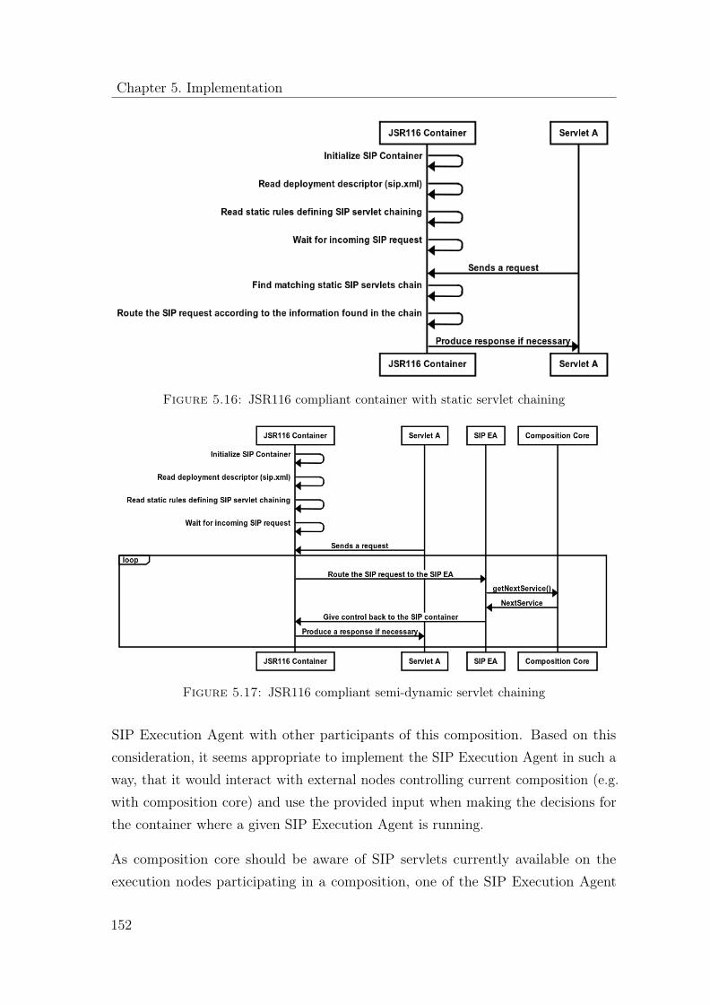
Chapter 5. Implementation
Figure 5.16: JSR116 compliant container with static servlet chaining
Figure 5.17: JSR116 compliant semi-dynamic servlet chaining
SIP Execution Agent with other participants of this composition. Based on thisconsideration, it seems appropriate to implement the SIP Execution Agent in such away, that it would interact with external nodes controlling current composition (e.g.with composition core) and use the provided input when making the decisions forthe container where a given SIP Execution Agent is running.
As composition core should be aware of SIP servlets currently available on theexecution nodes participating in a composition, one of the SIP Execution Agent
152

5.2 Composition framework
functionalities should be able to provide composition core with a list of all availableSIP servlets and applications deployed on a given SIP container. This set shouldinclude a set of unique identifiers (preferably unique SIP routes to any particularservlet, though some other options can be considered as well) and also referencesto the descriptions of these servlets in a format understandable by the compositioncore.
5.2.5.10 JSR116 based implementation of SIP Execution Agent
First of all, at the design/deployment time, it should be ensured that SIP.xml filecontains a reference to the SIP Execution Agent servlet in a description of a givenSIP application. By doing so, it is guaranteed that SIP container invokes the SIPExecution Agent in the scope of a current SIP session. It is proposed to put SIPExecution Agent as a last (optional) element in the chain of servlets related to agiven SIP application described by the SIP.xml file. This allows some servlets to beexecuted before SIP Execution Agent - ”outside” the composition control, so to say.This makes sense, since after SIP Execution Agent will be invoked, it will take overthe control over servlets execution for a given session.
Change in the SIP.xml file is the only one required at the design/deployment time.All other changes in container behavior happen at the runtime, namely, when theapplication containing a reference to SIP Execution Agent in its specification inSIP.xml file is selected for execution. In this case, SIP Execution Agent servlet isreached and starts controlling further invocations of servlets in scope of a currentsession. More precisely, SIP Execution Agent performs the following (1-5) sequenceof steps:
1. When a SIP Execution Agent is invoked, it will make a decision about whichservlet is to be executed next. This decision is based on the informationprovided by external composition control nodes (e.g. composition core).
2. When the composition decision for a next step is obtained, SIP Execution Agentwill enforce that the given servlet is executed as next and that SIP ExecutionAgent gets the control after it again. In case of JSR116, this is achieved viaquite legal SIP Servlet APIs calls, namely via pushRoute() functionality. SIP
153

Chapter 5. Implementation
Execution Agent simply pushes a SIP URI of the next servlet on the route.Then it also adds itself to the route, so that the control comes back. After theroute is modified in this way, SIP Execution Agent simply use a usual send()API method of the SIPServletRequest object, which gives the delivery controlto the standard SIP Servlet dispatcher of the SIP container.
3. Dispatcher will determine that this is a local route and deliver the SIP messageto the required servlet. Then next servlet’s address added in step 2 will beremoved from the route.
4. The required servlet processes the SIP message
5. The dispatcher gets a control again. It determines that the next destinationpoint is specified via a local route and that the next element on the routeis SIP Execution Agent. Therefore SIP Execution Agent is invoked and theprocess of selecting the next servlet starts again at the step 1
5.2.6 HTTP Execution Agent
The HTTP Execution Agent (HTTP EA) receives as input a service descriptionfor an external HTTP service, along with a set of input parameters and makes anHTTP request towards that service. As such it provides full support for HTTP andtherefore it is capable of making HTTP POST, PUT, DELETE and GET requests.This information is defined in the service description for HTTP services. In addition,in the same service description, one can define the endpoint of the HTTP service,specific headers to be included in the HTTP request and last but not least the bodyof the HTTP request. This set of parameters allows for complete support for everyRESTful invocation.
A special case of an HTTP service is SOAP based service also known as Web service.That is because SOAP based services, at least in their simplest form which does notrequire the existence of a SOAP stack such as the one provide by JAX-WS [91], canbe viewed like any other RESTful services with the exception they are defined asHTTP POST requests, with a Content-Type of ”application/soap+xml” and a bodythat complies to the format of SOAP.
An example of such a body is shown in listing 5.6:
154

5.2 Composition framework
<?xml version=" 1 .0 "?>2 <soap:Envelope xmlns:soap=" ht tp : //www.w3 . org /2001/12/ soap−enve lope "
soap : encod ingSty l e=" ht tp : //www.w3 . org /2001/12/ soap−encoding "><soap:Body xmlns:m=" ht tp : //www. example . org / s tock ">
4 <m:GetStockPrice><m:StockName>${company_name}</m:StockName>
6 </m:GetStockPrice></soap:Body>
8 </ soap:Envelope>
Listing 5.6: Annotated HTTP request payload
Input parameters can be provided as runtime variables that later on can be mapped tothe query string for RESTful services (i.e. http://url.com/query_parameter1=val1&query_parameter2=val2)and to specific placeholders in the body of the HTTP request (notice the specialnotation ${company_name} in the previous snippet).
There are three different variants of HTTP requests that are supported.
The first variant is request only: this entails that an HTTP request is being madeand the invocation thread is immediately released after that without waiting for theresponse from the external service.
The second variant is request-and-response: this entails that an HTTP request isbeing made and the invocation thread is blocked until the external service returns aresponse which later on converted to a set of runtime variables in order to becomeavailable to the application skeleton.
The third variant is non-blocking request-and-response: this entails that an HTTPrequest is being and the invocation thread is not blocked. However, as soon as theresponse from the external service is received, the particular session in the sharedstate manager is updated to include the runtime variables that are generated fromthat response.
An interesting feature available in our prototype, allows for the automatic generationof a service description from a WSDL description, due to the formal descriptionavailable. RESTful service descriptions, similarly to SIP service description need tobe crafted manually. Even though WADL exists, we decided not to include it in our
155

Chapter 5. Implementation
prototype, for the purposes of automatically generating a service description sinceWADL is not as widely adopted as WSDL.
The underlying implementation of the HTTP EA is achieved by using the async-http-client [81] so essentially the HTTP EA acts as a wrapper [61] to this externallibrary.
5.3 Composition framework
This section describes in detail the functionality of the composition core. Morespecifically, the first section is dedicated to the integration between the compositioncore and the rest of the components, comprising the composition framework. Thesecond section focuses on the composition core itself and describes and describes itsinternal structures and functionalities.
5.3.1 Composition framework component interaction
The composition core implements the creation of composite services by determiningthe structure of the composite service and defining appropriate services. The compo-sition core creates a composite service based on static information, i.e. applicationskeleton and services descriptions, and runtime information, e.g. user preferences,user request, resources allocation. A composite service is created element-by-element,so that every service in a composite service will be not determined until the previousservice in the composition is executed. This allows taking into account changesin the runtime environment that could occur at runtime. It should be noted thatthe composition core does not directly invoke services, rather the composition coresuggests to the EA, which services to be executed next, in order to create therequested composite service. This process consists of four main steps:
1. Invocation
• EA communicates with the composition core the composition core API
• Parameters provide information on:
– the external request (i.e. SIP packet, HTTP request)
156

5.3 Composition framework
– additional related state information
– reference to the composition session
2. State evaluation
• composition core evaluates the current state of the composition session
• Identifies the current state in the composite service
• Identifies ”loose ends” suitable for extending the composite service
– not terminated SIP sessions
– possibility to establish new chains
3. Query evaluation
• composition core evaluates all queries in the composition in order tonarrow down the amount of compatible services
– Composition-wide evaluation is necessary to cover feature interactionacross SIP sessions.
• Composition core determines the next to be executed service.
4. Composition decision
• Composition core returns the service to execute next.
After the execution of the indicated service the execution agents invokes contactsthe composition core again and either asks for the next service in the SIP servicechain or for an alternative service in case the suggested service could not be executedsuccessfully. In order to prevent resource collision between services, the compositioncore must ensure that all existing composite services within the overall user com-position session will stay valid and that all related queries are evaluated before aservice is suggested for execution.
The composition core and the Shared State Manager handle management of runtimeinformation and composition sessions jointly. Figure 5.18 illustrates in UML sequencediagram notation the four-step process of composite service interpretation.
A more detailed description of the process illustrated by an UML activity diagramis given in section 5.3.1.1.
157

Chapter 5. Implementation
Figure 5.18: Interpretation phases
Depending on the number of services in a service composition and the number ofrunning service compositions some optimizations in this cycle can be applied. Onepossible optimization is to reduce the number of loop interactions and the numberof requests from EA to the composition core. This can be done by returning bundlesof alternative services, so that the composition core provides to the EA not only theimmediate next service, but provided that the application skeleton allows this, twoor more next services at a time. This is achievable only if there are services in theapplication skeleton whose selection is not depended from the results of previousselections or other runtime information. However, the most time intensive task ofthe actual composition core internal processes is the evaluation of queries. This taskcan be optimized through pre-compilation of queries, so that only queries, that havereferences to the attributes of new services, will be evaluated.
5.3.1.1 Composition core activity diagram
When triggered by the execution agent the composition core will first try to identifyan existing session in the shared state manager that corresponds to the incoming
158

5.3 Composition framework
request (Activity 1 in Figure 5.19). If such a session does not exist, a new sessionwill be created (Activity 2). For the creation of a new session, the composition coreneeds to know which application skeleton should be used.
After a new session is created, we collect the list of actions that can be interpretedbased on their data dependencies (Activity 3). If the composition that correspondedto the request already exists, the status of last service execution within this composi-tion will be proved based on runtime information (Activity 4). If the atomic functionof the previously executed action has failed the composition core will simply drop theexecution of the application skeleton and raise an error event (Activity 5). The listof actions is executed in a non-blocking fashion when we reach Activity 9. However,before that what needs to be checked is whether or not the input parameters to theatomic function need to be casted to a different type than the one expected or notbefore we get to invoke the corresponding functions. This is done in Activities 6,7and 8.
5.3.1.2 Composition Core API
This section describes a preliminary API for communication between ExecutionAgent and Composition Core nodes. This interface provides functions for performingthese tasks:
• Informing the composition core about the set of services available on a givenservice container (e.g. SIP container or Web Services container) which couldparticipate in compositions.
• Consulting composition core for getting the information about next steps tobe executed by the execution agents
Listing 5.7 contains the definition of the Composition Core API as Java interface.Without loss of generality, other alternatives can also be used to describe thisinterface such as Web Services interface specified by means of the correspondingWSDL description will be used.
Composition Core API
159

Chapter 5. Implementation
Figure 5.19: Composition core activity diagram
/∗∗2 ∗ I n t e r f a c e r ep r e s en t i n g the API o f a composi t ion engine
∗ node and used by composi t ion agent .4 ∗
∗/6
public interface CompositionCore {8 /∗∗
∗ Provide CompositionCore wi th a curren t s t a t e o f the composi t ion10 ∗ agent and r e que s t the sequence o f s e r v i c e s to be executed next
∗12 ∗ @param s t a t e
160

5.4 Composition framework
∗ curren t s t a t e o f t h i s composi t ion agent14 ∗ @return sequence o f s e r v i c e s to execu te next
∗/16
public Serv iceSequence getServ i ceSequence (CAState s t a t e ) ;18
/∗∗20 ∗ Inform Composition Core about the s e t o f (SIP) s e r v i c e s a v a i l a b l e
on∗ the a p p l i c a t i o n s e r v e r and c on t r o l l e d by a g iven Composition Agent .
22 ∗∗ @param caId
24 ∗ i d o f a composi t ion o b j e c t∗ @param s e r v i c e s
26 ∗ s e t o f s e r v i c e s∗/
28
public void r e po r tAva i l a b l e S e r v i c e s (CAId caId , S e r v i c e s s e r v i c e s ) ;30
/∗∗32 ∗ Provide Composition Core wi th the current s t a t e o f the composi t ion
∗ agent and r e que s t the sequence o f s e r v i c e s s a t i s f y i n g thec on s t r a i n t s .
34 ∗∗ This func t i on i s u s u a l l y used by Web Se r v i c e s and o ther
36 ∗ API−based∗ components o f the composi t ion .
38 ∗
40 ∗ @param s t a t e∗ curren t s t a t e o f t h i s composi t ion agent
42 ∗ @param con s t r a i n t s∗ c on s t r a i n t s f o r r e qu i r ed s e r v i c e s
44 ∗ @return∗/
46
public Se rv i c eRe f s getMatch ingServ ices (CAState s tate ,S e rv i c eCons t r a i n t s c on s t r a i n t s ) ;
48
}
Listing 5.7: Composition Core API
161

Chapter 5. Implementation
5.4 Prototype architecture
As described in 4.4.2, one of the main constructs of the proposed language is an action.Actions can only have local data and the only way for an action to communicate datawith its environment is via effects – special variables whose value is copied to theparent, or to the adjacent action after the completion of the host action. The samenotion is re-used in the way the different components of the composition frameworkare communicating. More specifically, all of the aforementioned components existin isolation, having no shared state what so ever and communicate with each otherby exchanging asynchronous messages and by using callbacks. The philosophybehind this interaction has been popularized by programming languages such asErlang [10] where the developer is forced to consider a piece of software as a setof independent components that exchange messages. Moreover, when a particularcomponent crashes, it is good practice to let the component crash and immediatelyspawn a new instance of that component to try and resume instead of bloating theimplementation of a component with several defensive programming [96] constructsthat could only take care of most common kinds of failures (let-it-crash).
5.5 Quality of source code base
There are two reasons behind this endeavor for quantifying certain aspects of oursource code base. The first one is that of maintainability; Operating under theassumption that the recipients of this particular work is a group of developers thatare going to be responsible for maintaining this source code base, this section aspiresto become an aid for this group that helps identifying the most crucial parts of thissource code base. The second reason is to try and identify the impact of applying theCPS transformation to the source code base. The following metrics have been chosenfor this purpose; software lines of code, cyclomatic complexity, first order density,propagation cost and core size. Each metric is further explained in the correspondingsubsections of this chapter. The approach used in this section, for quantifying thehealth of our source code base is similar to the one used by Baldwin et al. [12]to review popular open-source and closed source projects such as Gnucash [114],Abiword [173], Google Chrome [134], Linux (kernel) [101], Mysql [116] and others.
162

5.5 Quality of source code base
Recently, the same set of metrics has been used by Almossawi in an analysis of theFirefox codebase maintainability [5].
5.5.1 Software lines of code
Software lines of code (SLOC), measures the number of executable lines of code,that is by excluding blank lines and lines that contain comments. It is one of theoldest and most widely used baselines to measure software quality [2]. Intuitively, asource code base that has more lines of code is more difficult to maintain. For thepurposes of this analysis, we measured the lines of codes of all java files (*. java)that were written for each of the different releases that we have made during thedevelopment of this prototype. This SLOC analysis also took into considerationJUnit [33] test files that we developed in order to assert proper functionality.
5.5.2 Cyclomatic complexity and essential cyclomatic com-
plexity
Cyclomatic complexity has been developer by Thomas McCabe in 1976. This metricdirectly measures the number of linearly independent paths through a program’ssource code. For the purposes of our analysis, we employ a variant of cyclomaticcomplexity that is known as essential cyclomatic complexity. Essential cyclomaticcomplexity is the Cyclomatic complexity after iteratively replacing all well structuredcontrol structures with a single statement. Structures such as if-then-else and whileloops are considered well structured. By removing all the structured sub graphs fromthe control graph and then calculating its cyclomatic complexity we calculate theessential cyclomatic complexity. A graph that has only the regular single entry/singleexit loops or branches will be reducible to a graph with complexity of one. Anybranches into or out of a loop or decision will make the graph non-reducible andwill have essential cyclomatic complexity >2.
163

Chapter 5. Implementation
Figure 5.20: Transitive closure
5.5.3 First order density
First order density is used in order to measure the number of direct dependenciesbetween files. It is calculated by building an adjacency matrix using a set of sourcecode files sorted by their hierarchical directory structure. The adjacency matrix(also known as Design Structure Matrix) is a set of rows and columns. If a filedepends on another file, then the intersection of those files, represented in rows andcolumns is marked with a number. First order density is calculated by measuringthe density of the adjacency matrix. This can be done by dividing the number ofnon-zero elements by the product of the size of the adjacency matrix.
first order density =nnz(A)
prod(size(A))(5.1)
5.5.4 Propagation cost
This metric is used for measuring direct and indirect dependencies between files.In practical terms it gives a sense of proportion of files that may be impacted, onaverage, when a change is made to a randomly chosen file. Propagation cost iscalculated by calculating the matrix density of the visibility matrix that is producedfrom the adjacency matrix mentioned for the purposes of measuring first orderdensity. The adjacency matrix produces the visibility matrix through transitiveclosure [172]. Pictorially, the function of transitive closure is shown in Figure 5.20.
The visibility matrix can be calculated by raising the first-order density matrix inconsecutive powers towards reaching its transitive closure ( 5.2 ).
164

5.5 Quality of source code base
Figure 5.21: Fan-in/Fan-out
N∑i=0
Ai (5.2)
However, this approach only yields specific n-level indirect relationships, for exampleraising the first-order-matrix to the power of two provides the second level of indirectdependencies. In our case, we chose to use the generalized approach towards transitiveclosure as defined by the Floyd-Warshal [126] algorithm.
5.5.5 Core, periphery, control and shared size
By creating a scatter plot of the different files available in our source code base inthe axes of fan-in and fan-out we produce these four metrics. Fan-in is calculated bysumming the elements of the i-th column of the visibility matrix, while fan-out iscalculated by summing the elements of i-th row of the visibility matrix. In otherwords fan-in describes the number of components that directly or indirectly dependon i while fan-out describes the number of components i directly or indirectly dependson.
A scatter plot represents the information split in four quadrants as shown in Fig-ure 5.21.
Core files are the files that are highly interconnected via a chain of cyclic dependencies.As such, various studies [102] have shown that core files are usually predisposed fordefects. Peripheral files are the files that do not depend on a lot of other files and do
165

Chapter 5. Implementation
not have a lot of files depend on them. Shared files are the files that do not dependon a lot of files but have a lot of files depend on them. Finally, control files are thefiles that depend on a lot of files but do not have a lot of files being dependent onthem.
5.5.6 Data set
During the development of this prototype we used a subversion repository [38] tostore the different development iterations. Overall a set of 3998 revisions has beencreated. From that set we promoted 11 revisions to become the releases for thisprototype since each one of those represents a milestone. Those releases and theircorresponding characteristics of each release are the following:
1. Coarse-grained: The original coarse-grained implementation — created for thepurposes of simulating rival execution frameworks
2. Coarse-grained with HTTP EA: The coarse-grained with an HTTP EA
3. Coarse-grained with HTTP and SIP EA: Coarse grained with HTTP and SIPEA
4. Coarse-grained with AOP and events: An updated version of the coarse-grainedcore with support for Aspect Oriented programming constructs and events
5. Coarse-grained with HTTP EA: The updated coarse-grained core with anupdated HTTP EA
6. Coarse-grained with HTTP and SIP: The updated coarse-grained core withimproved HTTP and SIP EA
7. Coarse-grained with HTTP, SIP and JBI EA: Updated coarse grained corewith improved HTTP, SIP and JBI EA
8. Fine-grained: The fine-grained execution framework
9. Fine-grained with HTTP EA: Fine-grained execution framework with improvedHTTP EA
166

5.5 Quality of source code base
Mean Median Standard deviation Min MaxLines of code 58836.55 51193 30706.43 22210 105116Sum essentialcyclomaticcomplexity
6020.91 5315 2968.10 2509 10441
First order den-sity
0.0033 0.0034 0.0003 0.0029 0.0036
Propagation cost 0.0516 0.0532 0.0150 0.0264 0.0753Core size 0.1308 0.1703 0.0889 0 0.2164Files 686.73 566 355.92 292 1217
Table 5.9: Cumulative statistics (n=11)
10. Fine-grained with HTTP, SIP EA: Fine grained execution framework withHTTP and SIP EA
11. Fine-grained with HTTP, SIP and JBI EA: Fine-grained execution frameworkwith HTTP, SIP and JBI EA.
Table 5.9 shows some descriptive statistics for the 11 source code bases.
5.5.7 Data processing
To process these 11 data sets we used a program called Understand [147] in its 15-dayevaluation period. Understand is a static analysis tool that can analyze .java fileswithout the need of having those files compiled, or the requirement to have all thesefiles collected in the workspace of an IDE, like other Java static analysis tools forJava would require. More specifically, Understand provides for us the measurementsfor the amount of files available in each source code base, the sum of the essentialcyclomatic complexity and the amount of lines of code. In addition, understandprovided for us the corresponding file dependency matrix for each source code base.
Later on we continue by processing each file dependency matrix with Mathworks’Matlab in order to produce first order density, propagation cost, core size, peripherysize, control size and shared size. The basis for these six metrics is the file dependencymatrix produced by Understand. The file dependency matrix allows us to createthe first order density matrix, by replacing the amount of references between fileswith the number 1, instead of the actual count that was produced by Understand.
167

Chapter 5. Implementation
Figure 5.22: First order density
First-order density is calculated by computing the density of that matrix. Usingtransitive closure, we later on produce the visibility matrix. As shown previouslyin Figure 5.20 the visibility matrix describes both direct and indirect relationshipsamong files.
An interesting observation to make here are the emerging dependencies that areproduced as soon as the transitive closure is calculated (Figure 5.22 and Figure 5.23).
To produce the metrics for core, periphery, control and shared size we calculated thecorresponding fan-in and fan-out of each file and later on measured the amount ofeach files that appears in each quadrant.
Algorithm 1 can be used for measuring the amount of file occurrences in eachquadrant.
168

5.5 Quality of source code base
Figure 5.23: Visibility matrix
Algorithm 1 Counting occurrences per quadrant of fan-in/fan-out chartSet A to be a two-dimensional matrix containing all elementsSet x− boundary to be the middle of the x axis for matrix ASet y − boundary to be the middle of the y axis for matrix Afor j ← 1, n do
if A(1, j) >= x− boundary & A(2, j) < y − boundary then
shared++else if A(1, j) < x− boundary & A(2, j) < y − boundary then
peripheral++else if A(1, j) < x− boundary & A(2, j) >= y − boundary then
control++else if A(1, j) >= x− boundary & A(2, j) >= y − boundary then
core++end if
end for
169

Chapter 5. Implementation
Figure 5.24: Sum of essential cyclomatic complexity
5.5.8 Overall findings
The sum of essential cyclomatic complexity (Figure 5.24) shows an increasing trend,especially at the point where the fine-grained version of the execution framework isintroduced, where the sum of essential cyclomatic complexity jumps from 4175 to8202 (96.45% increase). However, this increase is justified since the source code basethat contains the fine-grained core also contains the coarse-grained and therefore thesum of essential cyclomatic complexity shows a significant growth. As we later onshow once we describe the sum of essential cyclomatic complexity per module, thesum of essential cyclomatic complexity actually drops when the fine-grained core isanalyzed in separation from the coarse-grained.
The amount of lines of code (Figure 5.25) increases in a similar pattern as the sum ofessential cyclomatic complexity. Similarly to the previous figure, we notice a sharpincrease in the amount of lines of code when moving from the coarse-grained coreto the fine-grained one, rising from 39610 to 80335 (102% increase). As before, theincrease is explained by the fact that both the coarse-grained and the fine-grainedcore are now included into the same source code base. Even though the choice ofhaving both versions in the same source code base, seems redundant, functionally-wise, since the fine-grained core can imitate very nicely the characteristics of the
170

5.5 Quality of source code base
Figure 5.25: Lines of code
coarse-grained, we decided to keep the original core in our source code base inorder to have more accurate results when comparing the performance between ourproposed fine-grained core and the coarse-grained approaches used by our rivals.
Overall the observation that cyclomatic complexity increases in a similar patternas lines of code denotes a negative attribute to the maintainability of the sourcecode. However, in this case, the increase is justified since we are only examininga prototype that has been developed to include new features, therefore it shouldincrease in complexity.
First order density (Figure 5.26) shows overall a decreasing trend. More specifically,the decrease is observed with the introduction of the fine-grained core. Morespecifically, first order density drops from 0.0033 to 0.0031 ( 6%) and if we compareto the first order of density of the first release the decrease is about 13%. The dropin first order density shows that the direct dependencies between files are decreasing.On average, first order density is 0.0032 with a standard deviation of 0.0002. Thisentails that changing any randomly chosen file has a direct impact on other 2 files.
Propagation cost (Figure 5.27) shows to increase steadily (approximately 45%),throughout the progression of the development process where the different executionagents and variations of cores are being introduced. On average we estimate the
171

Chapter 5. Implementation
Figure 5.26: First order density
propagation cost to be 0.0516 with a standard deviation of 0.014. This observationentails that a change in any random file may have eventually an indirect impact on35 other files.
Core files (Figure 5.28) are detected with the introduction of AOP and events inthe coarse-grained approach. Prior to that our source code base was deprived ofcore files; it consisted of 96% periphery files, 1.4% control files and 2.2% sharedfiles. Thereafter, we notice that core-size decreases with the introduction of thefine-grained approach, only to increase later on to the same degree as it was withAOP event based, after the introduction of the HTTP, SIP and JBI execution agents.
5.5.9 Per module findings
On a per module level, we proceed to analyze the different key components of oursource code base in isolation, as opposed to the previous measurements which insome cases included combinations of components. In this section, the fine-grainedcore, the coarse grained and the HTTP, SIP and JBI EAs are decoupled and areanalyzed separately.
172

5.5 Quality of source code base
Figure 5.27: Propagation cost
Figure 5.28: Core size
173

Chapter 5. Implementation
Figure 5.29: Essential cyclomatic complexities per module
The main motivation behind undergoing a per module analysis of our source codebase was to have a clearer understanding of the impact, the CPS transformation hadin our source code base, in the process of transcending from a coarse-grained to a fine-grained core. To our surprise, we observe (Figure 5.29) that the complicated processwe underwent, in order to migrate from a coarse-grained composition core, to a fine-grained one, has yielded in a reduction in the sum of cyclomatic complexity. Eventhough the reduction is small, from 2509 to 2361 ( 5% decrease) it is an importantone since the fine-grained core is capable of performing the same functionality asthe coarse-grained one (blocking calls in synchronous mode) and its expressed witha smaller amount of essential cyclomatic complexity. However, the same trait isnot maintained in the execution agents. The transition from a coarse-grained to afine-grained core yields increases in the sum of essential cyclomatic complexity forthe SIP and HTTP EAs. More specifically for the SIP EA, we see two consecutiveincreases of 13% and then 80%. The HTTP EA shows similar traits, receivingincreases in complexity of 107% and 80%. JBI Execution Agent (JBI EA) due toits simplicity only sees a 5.1% increase. The increase observed in the EAs is welljustified since the fine-grained approach requires each EA to break its functionalityin several phases that are later on reported back to the core.
With regards to first order density (Figure 5.30) we see that the fine-grained core
174

5.5 Quality of source code base
Figure 5.30: First order density per module
has a smaller first order density that the coarse-grained one, decreasing from 0.0036to 0.0031 ( 13%). First order density remains stable for the SIP, HTTP and JBIEAs.
We notice a sharp increase in the propagation cost (Figure 5.31) for the fine-grainedcomposition core, increasing from 0.0264 to 0.0582 ( 120%). Each EA also sees anincrease in propagation cost. SIP EA increases 0.0045 to 0.0079 ( 75%) and then to0.0097 ( 22%). HTTP EA increases from 0.0042 to 0.0052 ( 23%) and then to 0.0112( 115%). JBI EA increases from 0.0017 to 0.0032 ( 88%). The increase in propagationcost is justified, since the updated EAs now communicate with fine-grained coreusing callbacks, and therefore they are indirectly dependent to a greater amount offiles than they used to.
Finally yet importantly, the fine-grained core has a core size (Figure 5.32), as opposedto the coarse grained one that is deprived of one as we have mentioned earlier. Thesignificant difference ( 1710%) between the core size of the fine-grained core andthat of the EA is justified since the core is much larger and much more integral tothe architecture as opposed to the EA. The shift to the fine-grained core also yieldsincreases in the core sizes of the EAs. While all the EA seem to be deprived of a setof core files in the coarse-grained version, the acquire one after the introduction of
175

Chapter 5. Implementation
Figure 5.31: Propagation cost per module
Aspect Oriented Programming (AOP) and events and later on with the fine-grainedcore. SIP EA’s core size increases from 0.0079 to 0.0097 ( 22%). HTTP EA’s coresize increases from 0.002 to 0.0093 ( 365%). JBI EA’s core size increases from 0.0202to 0.0323 ( 59%).
5.6 Summary
The outcome of this work is an asynchronous composition core that is scalable;limited by the amount of available memory and not by the number of availableprocessing threads. Another characteristic of the asynchronous composition core isrobustness as system starvation is not possible. These findings are later on evaluatedempirically in 6.1. In this section we have provided implementation details thatdescribe in detail the internal operations of the composition core, a module that canbe seen as an interpreter of a concurrent programming language with a optional typesystem, the application skeleton repository that employs a graph database in orderto deal with data dependencies, the shared state manager which is a distributedkey value store where session information is maintained for every instantiation ofan application skeleton, a services repository that maintains a collection of service
176
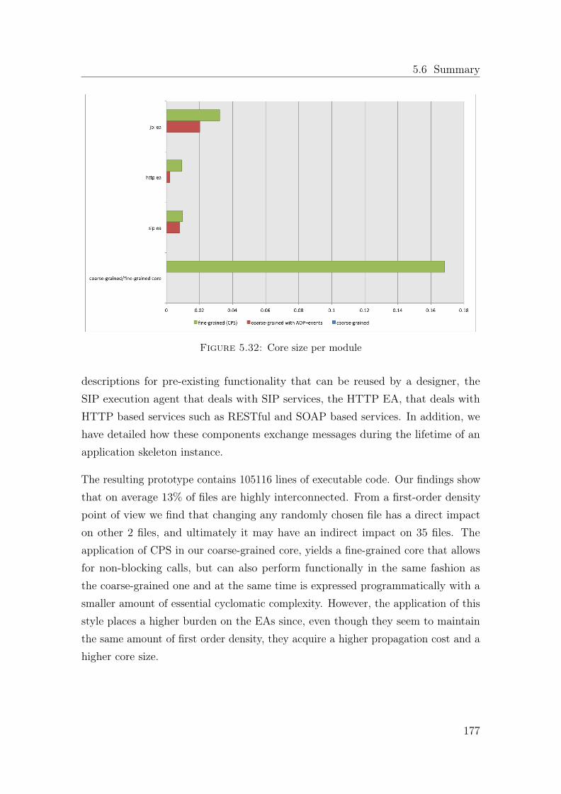
5.6 Summary
Figure 5.32: Core size per module
descriptions for pre-existing functionality that can be reused by a designer, theSIP execution agent that deals with SIP services, the HTTP EA, that deals withHTTP based services such as RESTful and SOAP based services. In addition, wehave detailed how these components exchange messages during the lifetime of anapplication skeleton instance.
The resulting prototype contains 105116 lines of executable code. Our findings showthat on average 13% of files are highly interconnected. From a first-order densitypoint of view we find that changing any randomly chosen file has a direct impacton other 2 files, and ultimately it may have an indirect impact on 35 files. Theapplication of CPS in our coarse-grained core, yields a fine-grained core that allowsfor non-blocking calls, but can also perform functionally in the same fashion asthe coarse-grained one and at the same time is expressed programmatically with asmaller amount of essential cyclomatic complexity. However, the application of thisstyle places a higher burden on the EAs since, even though they seem to maintainthe same amount of first order density, they acquire a higher propagation cost and ahigher core size.
177

Chapter 6
Evaluation
This chapter provides an evaluation of our work. For this to be accomplished,different aspects of the composition framework and SCaLE are evaluated usingdifferent evaluation criteria. We start by evaluating the composition framework.More specifically, we measure the overhead (delay) introduced by the compositionframework and verify its robustness under heavy load. Our aim is to show throughempirical experimentation that the overhead introduced by the composition frame-work is minimal and that the system is stable after running for a long period, havingreceived a large amount of requests.
Then we move on to a qualitative evaluation of SCaLE. More specifically we compareSCaLE to its two closest rivals, WS-BPEL and BPMN 2.0. Even though ourcomparison focuses intentionally on these two languages, due to the fact that theyare widely used and both have formally defined execution semantics, the qualitativeevaluation approach can be used to compare our language with any other languagethat is available in the state of the art. The qualitative evaluation compares theselanguages in terms of abstraction, flexibility, support for the integration of serviceswith different interfaces using different communication protocols, usability of thelanguage for business process developers without an IT-background and finallysupport of workflow patterns.
179

Chapter 6. Evaluation
6.1 Composition core performance analysis
We begin our evaluation by comparing variant configurations of our fine-grainedcomposition core to a coarse-grained, dedicated thread implementation that aims atmimicking the behavior of the closest rivals to this proposed approach which aresystems such as ActiveBPEL, so workflow engines that have been designed to bedeployed to as servlets on top of containers. In a coarse-grained dedicated threadapproach [50], dedicated threads handle requests to the composition core: each oneis responsible for the execution of each action in an application skeleton until itscompletion. Invocations of external services, performed by service template actions,are blocking the threads until a result is available.
In our fine-grained composition core, the execution of an application skeleton isdivided into smaller tasks. Thereafter, several pools of worker threads that are nottied to a specific application skeleton process these tasks. Whenever an applicationskeleton has to wait for the execution of an external service, the corresponding taskis put on a waiting list and will be retrieved by a worker thread together with itscontext information when the result of the external invocation is available. Someimprovements to the supported protocols, such as the support for Comet [49] in HTTPallow asynchronous notification of the caller when a result is available. Together,these various improvements allow the composition core to be fully asynchronous andto avoid blocking threads and other resources during the execution of an applicationskeleton.
The fine-grained core can be deployed in two ways: inside a container (usuallythe application server SailFin) or standalone. In the latter case, the compositionframework provides its own HTTP server (set of HTTP listening threads) insteadof relying on the infrastructure provided by the container. Standalone deploymentreduces the overhead that is added by the application server and allows for a moredirect management of threads and resources.
In order to evaluate these improvements, a number of performance tests have beendone with the coarse and fine-grained versions of the composition core with twomain goals:
• Measure the overhead (delay) introduced by the composition framework
180

6.1 Composition core performance analysis
• Verify the robust behavior of the composition framework under heavy load.
For most of the tests, five different variations are compared:
• The coarse-grained composition core inside SailFin
• The fine-grained composition core in ”synchronous mode” inside SailFin
• The fine-grained composition core in ”asynchronous mode” inside SailFin
• The fine-grained composition core in ”synchronous mode” without a container(standalone)
• The fine-grained composition core in ”asynchronous mode” without a container(standalone)
The following two subsections 6.1.1, 6.1.6 describe our findings when testing thedifferent variations from the HTTP and SIP perspectives.
6.1.1 HTTP tests
This subsection describes the testing environment utilized for our HTTP tests. Atest client makes a HTTP request to the composition framework (CF) and invokes anapplication skeleton. This application skeleton will in turn invoke a single externalservice over HTTP. This test service returns a response after a specified delay, inorder to simulate what happens with real external services that can take an arbitraryamount of time to deliver their response. The response ends the execution of thesimple application skeleton and allows the composition framework to return theresult to the test client.
Some of the tests were done using different application skeletons: a special applicationskeleton that was returning immediately and another one that provided a delayedresponse without invoking any external services. This allows us to compare withand without external services and to evaluate how much the invocation of externalservices contributed to the end-to-end delay.
181

Chapter 6. Evaluation
Figure 6.1: Test setup
The tests were run in two different configurations: one in which the test client,composition framework and test server were deployed on three different machinesconnected by a 100Mbit Ethernet network, and another configuration in which allthree were deployed on the same machine. The first configuration minimizes theimpact on CPU and memory that the client and server could have on the executionof the composition framework. The second one minimizes the impact of the networkand interference from other machines that were also connected to the same switch.
In both cases, the machine running the composition framework had these character-istics:
• CPU: Intel(R) Core(TM)2 Duo CPU E6550 @ 2.33GHz
• RAM: 8 GB
• Operating system: Linux (Ubuntu 10.04, kernel 2.6.32-26-server)
• Java version: 1.6.0_20
• Java configuration: -Xms128M -Xmx256M (standalone) or -Xmx512m (SailFin)
In the ”split” configuration, the machine running the test client was identical tothe one running the composition framework, except that it was running a slightlydifferent version of Linux (Debian 5.0, kernel 2.6.26-2-amd64). The machine runningthe test server had these characteristics:
• CPU: Intel(R) Xeon(R) CPU E5504 @ 2.00GHz
• RAM: 8 GB
• Operating system: Linux (Debian 5.0, kernel 2.6.26-2-amd64)
182

6.1 Composition core performance analysis
• Java version: 1.6.0_22
The test client that we used for HTTP tests was JMeter [76]. We configured it tosimulate a number of concurrent clients (between 100 and 500 or more) makingrequests to the composition framework in a loop. Most tests were run with 10000to 30000 requests for each measurement point. The end-to-end duration of eachrequest was measured, as well as the throughput in number of requests per second.In addition we collected information about the error rate, minimum response time,maximum response time, 90% percentile for the response time and overall duration.
The test server that we used was written by us for these performance tests. Itsmain function was to accept HTTP requests and wait a specified amount of timebefore returning. This functionality was implemented were easily by utilizing theThread.sleep(duration) function provided by Java.
The tests were automated as much as possible so that we could run them with thefive deployments of the composition framework: coarse-grained dedicated thread,fine-grained with and without SailFin and in synchronous or asynchronous modes.During the tests we varied the number of simultaneous clients, the delay on theserver side, the number of listening threads for the composition framework, etc.
The following JVM options have been used [113]:
-server: a virtual machine (VM) tuned for server that is specially tuned to maximizepeak operating speed — it is intended for executing long-running server applications,that need the fastest possible operating speed more than a fast start-up time orsmaller runtime memory footprint
-Xms2048m: This option sets the initial minimum Java heap size
-Xmn128m: Sets the heap size for the young generation
-Xmx2048m: This option sets the maximum Java heap size
-XX:+UseParNewGC: Enables the parallel copying collector; this collector parallelizesthe copying collection of multiple threads which is more efficient than the originalsingle-thread copying collector for multi-CPU machines
-XX:+UseConcMarkSweepGC: Enables the concurrent low pause collector
183
Chapter 6. Evaluation
-XX:ParallelGCThreads=2: Sets the number of garbage collector threads
-XX:NewRatio=2: Ratio of new/old generation sizes
-XX:+UnlockDiagnosticVMOptions: Enable processing of flags relating to fielddiagnostics
-XX:SurvivorRatio=8:Ratio of eden/survivor space size
-XX:PermSize=64m: Default size of permanent generation
-XX:MaxPermSize=192m: Maximum size of permanent generation
-XX:LargePageSizeInBytes=2m: Large page size to let VM choose the page size
-XX:MaxTenuringThreshold=8: Maximum value for tenuring threshold
-XX:CMSInitiatingOccupancyFraction=1: Sets the percentage of the current tenuredgeneration size
Moreover, the composition framework was configured to exchange information amongits constituent components as Plain old Java Objects (POJOs) [59] in order tominimize serialization/deserialization overhead, debug information was not collectedand stored and last but not least session information per application skeleton instancewas removed after the completion of each application skeleton.
After a first series of tests, we discovered that under a very high load, the compositionframework seemed to perform well for the first few thousand requests, but aftera while it produced a rapidly increasing number of errors. Our test server alsoexhibited the same behavior. We identified this problem as being caused by thedefault limit of file descriptors that a process can open simultaneously (in this case,TCP sockets). Increasing this default number in /etc/security/limits.conf from 1024to 60000 solved the problem and allowed us to run the tests even with a very highnumber of simultaneous requests.
184

6.1 Composition core performance analysis
Figure 6.2: Average response time of coarse-grained approach in Sailfin (100listeners)
6.1.2 Coarse-grained vs fine grained task granularity — re-
sponse time
A first series of tests that immediately shows the advantages of fine-grained taskgranularity of the asynchronous composition core compares the end-to-end responsetime for increasing server-side delays with different numbers of simultaneous clients.
In graphs 6.2 and 6.3, the dotted line shows the ”ideal delay”, which is the delayrequested from the test service. If the composition framework, the test server andthe network were perfect and had no overhead, then the end-to-end response timewould be equal to the requested delay.
For these tests, the application server SailFin was configured with 100 listeningthreads for HTTP. This is much higher than the default 5, but we saw that it wasnecessary to increase it because otherwise the comparison would not have been fairsince SailFin would have been unable to handle a large number of simultaneousrequests. The standalone version of the composition framework was configured withits default 64 listeners, which was sufficient for this test.
185

Chapter 6. Evaluation
Figure 6.3: Average response time of fine-grained composition core
Each point on these graphs represents the end-to-end time, averaged over 30000requests. By comparing the coarse-grained dedicated thread approach to the fine-grained composition core, we can mainly observer two significant differences:
1. The fine-grained core is always close to the ideal delay (dotted line), regardlessof the number of simultaneous clients. The coarse grained dedicated threadapproach performs correctly when the number of clients is equal to its numberof listening threads (100) but its performance is significantly degraded whenthe number of client increases to 150 or 200.
2. On the left side of the graph (low delays), the fine-grained composition coreperforms better than the coarse-grained dedicated thread approach, whichmeans that it introduces less overhead.
6.1.3 Coarse-grained vs fine grained task granularity — through-
put
The throughput measured for the same test as above shows the same trends: thefine-grained composition core scales much better than the coarse-grained one because
186
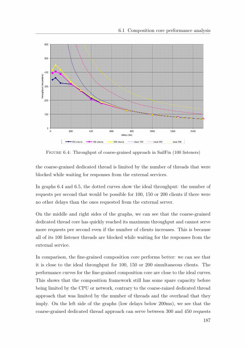
6.1 Composition core performance analysis
Figure 6.4: Throughput of coarse-grained approach in SailFin (100 listeners)
the coarse-grained dedicated thread is limited by the number of threads that wereblocked while waiting for responses from the external services.
In graphs 6.4 and 6.5, the dotted curves show the ideal throughput: the number ofrequests per second that would be possible for 100, 150 or 200 clients if there wereno other delays than the ones requested from the external server.
On the middle and right sides of the graphs, we can see that the coarse-graineddedicated thread core has quickly reached its maximum throughput and cannot servemore requests per second even if the number of clients increases. This is becauseall of its 100 listener threads are blocked while waiting for the responses from theexternal service.
In comparison, the fine-grained composition core performs better: we can see thatit is close to the ideal throughput for 100, 150 or 200 simultaneous clients. Theperformance curves for the fine-grained composition core are close to the ideal curves.This shows that the composition framework still has some spare capacity beforebeing limited by the CPU or network, contrary to the coarse-rained dedicated threadapproach that was limited by the number of threads and the overhead that theyimply. On the left side of the graphs (low delays below 200ms), we see that thecoarse-grained dedicated thread approach can serve between 300 and 450 requests
187

Chapter 6. Evaluation
Figure 6.5: Throughput of fine-grained composition core
per second. The fine-grained composition core performs better and can serve between400 and 600 requests per second.
The small dip in the yellow curve for the 100ms delay with the fine-grained composi-tion core is most likely due to a temporary disturbance of the test machine whilethis test was running. A subsequent re-run of this test showed that the compositionframework was able to serve a bit more than 500 requests per second instead of the454 shown on this graph. But we decided to keep the original (unaltered) test dataanyway, instead of replacing it to hide this temporary glitch.
6.1.4 Comparison with a high number of simultaneous clients
We repeated these tests with a higher number of simultaneous clients: 500 andmore, up to 1000. For a very high number of clients, the coarse-grained dedicatedthread approach running in SailFin started producing timeouts. Even the fine-grained composition core had some problems because the machine was running outof available port numbers: many of the TCP ports were in the TIME_WAIT state,preventing them from being reused immediately.
The graphs for 500 simultaneous clients are shown in Figure 6.6 and Figure 6.7.
188

6.1 Composition core performance analysis
Figure 6.6: Average response time of coarse-grained approach in Sailfin (100listeners) and 500 simultaneous clients
The coarse-grained dedicated thread approach could not cope with the high numberof simultaneous clients because most of its threads are blocked while waiting for aresponse from the external service. As a result, the delays accumulate and quicklybecome unacceptable, causing timeouts on the client side. Although it is not visibleon the graph because it is out of range, the average end-to-end response time fora server-side delay of 1500ms is around 7 seconds for the coarse-grained dedicatedthread approach.
Here we see that the results of the fine-grained composition core are not as good asexpected and the response times vary a lot. For relatively high delays (right side ofthe graph, delay >= 1000ms), the results are relatively close to the ideal case. Butfor the smaller delays on the left side of the graph, the average response time seemsto be a bit unpredictable even if it is better than for the coarse-grained dedicatedthread approach.
We identified this problem as coming probably from one of the libraries that we usefor HTTP Comet handling: it does not seem to release its resources fast enoughwhen handling a large number of requests, which causes a somewhat erratic behavior.
189

Chapter 6. Evaluation
Figure 6.7: Average response time of fine-grained composition core with 500clients
We are investigating this further and will try to optimize the code in order to improvethe results.
6.1.5 Comparison with other configurations of the fine-grained
core
The fine-grained composition core can be run in synchronous or asynchronousmode. The synchronous mode is closer to the coarse-grained dedicated threadapproach although it benefits from other improvements in the code. The compositionframework can also be deployed without a container (as shown in the graphs above)or within SailFin. In order to compare the performance of the various configurationsand to evaluate the relative impact of the container and of the synchronous orasynchronous mode, we have also tested the following deployments of the compositionframework:
• Standalone synchronous
• Asynchronous in SailFin
190

6.1 Composition core performance analysis
Figure 6.8: Average response time of fine-grained composition core in synchronousmode
6.1.5.1 Standalone synchronous — Response time and throughput
Compared to the asynchronous standalone mode, the synchronous mode shows abehavior similar to the coarse-grained dedicated thread approach when the delays arerather long: the slow responses from the external service are blocking the listeningthreads and cause all other requests to be queued up. The middle and right sidesof the graphs above are very similar to the results of the coarse-grained dedicatedthread approach.
On the left side of the graphs (delays below 200ms), the results are better thanthe coarse-grained dedicated thread approach but not as good as the fine-grainedcomposition core. This means that the composition framework benefits from theimprovements of the fine-grained composition core and the more efficient standalonemode, but is slightly limited by the synchronous mode.
6.1.5.2 Asynchronous in SailFin — Response time and throughput
We see in graphs 6.10 and 6.11 that the blue and purple curves (100 and 150 clients)are better than the coarse-grain dedicated thread approach in SailFin, but not
191
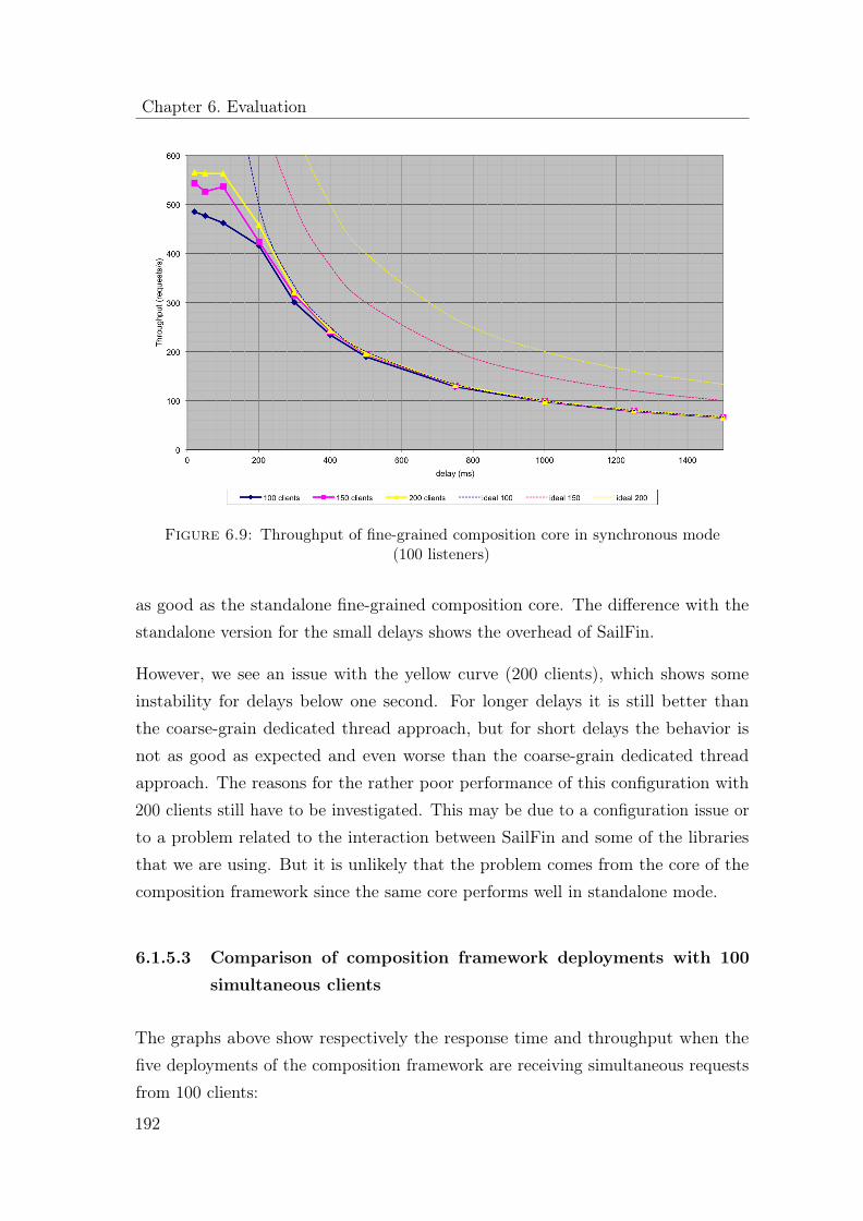
Chapter 6. Evaluation
Figure 6.9: Throughput of fine-grained composition core in synchronous mode(100 listeners)
as good as the standalone fine-grained composition core. The difference with thestandalone version for the small delays shows the overhead of SailFin.
However, we see an issue with the yellow curve (200 clients), which shows someinstability for delays below one second. For longer delays it is still better thanthe coarse-grain dedicated thread approach, but for short delays the behavior isnot as good as expected and even worse than the coarse-grain dedicated threadapproach. The reasons for the rather poor performance of this configuration with200 clients still have to be investigated. This may be due to a configuration issue orto a problem related to the interaction between SailFin and some of the librariesthat we are using. But it is unlikely that the problem comes from the core of thecomposition framework since the same core performs well in standalone mode.
6.1.5.3 Comparison of composition framework deployments with 100
simultaneous clients
The graphs above show respectively the response time and throughput when thefive deployments of the composition framework are receiving simultaneous requestsfrom 100 clients:
192

6.1 Composition core performance analysis
Figure 6.10: Average response time of fine-grained composition core in asyn-chronous mode in SailFin (100 listeners)
Figure 6.11: Throughput of fine-grained composition core in asynchronous modein Sailfin (100 listeners)
193

Chapter 6. Evaluation
Figure 6.12: Average response time comparisons for 100 simultaneous clients
Figure 6.13: Throughput comparison for 100 simultaneous clients
194

6.1 Composition core performance analysis
The coarse-grained composition core inside SailFin
• The fine-grained composition core in ”synchronous mode” inside SailFin
• The fine-grained composition core in ”asynchronous mode” inside SailFin
• The fine-grained composition core in ”synchronous mode” without a container(standalone)
• The fine-grained composition core in ”asynchronous mode” without a container(standalone)
As there are also 100 listening threads, the difference between the synchronous andasynchronous modes should be minimal because each thread can take care of oneclient so there should be no client waiting for an available thread. This is indeedwhat we can see on these graphs: the asynchronous and synchronous modes ofthe standalone deployment (light blue and dark blue lines) are very close to eachother for all requested delays, and the asynchronous and synchronous modes of thedeployment in SailFin (light green and dark green lines) are also very close to eachother.
We can also see on these graphs that the standalone mode is always more efficientthan the deployment within SailFin: the blue lines show a better performance thanthe green or red lines. Among the SailFin deployments, the fine-grained compositioncore (green lines) is slightly better than the coarse-grained dedicated thread approach(red lines), especially concerning the throughput.
6.1.5.4 Comparison of composition framework deployments with 150
simultaneous clients
The graphs below are similar to the previous ones, except that now there are150 simultaneous clients for only 100 listening threads. This means that in thesynchronous (blocking) mode, some of the requests must be queued up while theyare waiting for a thread to become available.
For the standalone deployment, we see that the light blue and dark blue lines areclose to each other for low delays (100ms or less) on the left side of the graphs. But
195

Chapter 6. Evaluation
Figure 6.14: Response time comparison for 150 simultaneous clients
as the delay increases towards the right side of the graphs, the asynchronous mode(light blue line) gets closer to the ideal case (dotted line), while the synchronousmode adds more delays and has a lower throughput.
For the deployment inside SailFin, the behavior is the same: the light green anddark green lines get further apart from each other on the right side of the graphs.
However, we can see that the performance of the asynchronous mode inside SailFin(light green line) could probably be improved because it is not always better thanthe coarse-grained dedicated thread approach (red line). Again, this is probably aconfiguration issue or some interaction between the libraries that we are using andthe container SailFin.
In summary, we have seen in this test and the previous ones that the fine-grainedcomposition core in asynchronous mode deployed without container (standalone)always gives a better performance than the coarse-grained dedicated thread approachdeployed inside SailFin, sometimes by a large margin. The fine-grained compositioncore deployed inside SailFin is often better than the coarse-grained dedicated threadapproach, but could still be improved.
196

6.1 Composition core performance analysis
Figure 6.15: Throughput comparison for 150 simultaneous clients
6.1.6 SIP tests
Although the protocols and message exchange patterns are different for SIP andHTTP, the test setup for SIP was similar to the one used for HTTP: one SIP client,one SIP server and the composition framework (CF) between them.
For all SIP tests, the client and the server were implemented using SIPp [63] withclient and server scripts derived from the standard SIPStone UAC and UAS responder.The composition framework was tested with a simple application skeleton that wastriggering a simple SIP service, either as a SIP proxy or as a back-to-back user agent.
6.1.6.1 Composition framework overhead
To evaluate the performance impact of the presented solution, we run the aforemen-tioned performance test to measure the overhead introduced by the compositionframework. Our goal is to verify that the end-to-end delay added by the presence ofthe composition framework does not introduce significant overhead. In order to dothat, we compared the performance of the system under load with and without thecomposition framework. The test with the composition framework involved a simple
197
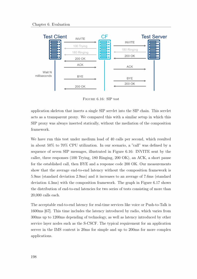
Chapter 6. Evaluation
Figure 6.16: SIP test
application skeleton that inserts a single SIP servlet into the SIP chain. This servletacts as a transparent proxy. We compared this with a similar setup in which thisSIP proxy was always inserted statically, without the mediation of the compositionframework.
We have run this test under medium load of 40 calls per second, which resultedin about 50% to 70% CPU utilization. In our scenario, a ”call” was defined by asequence of seven SIP messages, illustrated in Figure 6.16: INVITE sent by thecaller, three responses (100 Trying, 180 Ringing, 200 OK), an ACK, a short pausefor the established call, then BYE and a response code 200 OK. Our measurementsshow that the average end-to-end latency without the composition framework is5.9ms (standard deviation 2.9ms) and it increases to an average of 7.6ms (standarddeviation 4.3ms) with the composition framework. The graph in Figure 6.17 showsthe distribution of end-to-end latencies for two series of tests consisting of more than20,000 calls each.
The acceptable end-to-end latency for real-time services like voice or Push-to-Talk is1600ms [67]. This time includes the latency introduced by radio, which varies from300ms up to 1200ms depending of technology, as well as latency introduced by otherservice layer nodes such as the S-CSCF. The typical requirement for an applicationserver in the IMS context is 20ms for simple and up to 200ms for more complexapplications.
198

6.1 Composition core performance analysis
Figure 6.17: Distribution of call latencies
In this context, the overhead added by the composition framework is rather small:an average of less than 2ms in our test, which is less than 10 per cent of timeavailable for simple applications or less then 0.2 per cent of end-to-end latency. Thelow overhead added by the composition framework makes it suitable for use in atelecommunication network, and even more with potential optimizations of softwareand hardware.
6.1.7 SIP and HTTP test conclusions
We measured the performance of the composition core with a large number ofsimultaneously running applicaiton keletons. We compared five different variationsof the proposed composition core:
• The coarse-grained composition core inside SailFin
• The fine-grained composition core in ”synchronous mode” inside SailFin
199

Chapter 6. Evaluation
• The fine-grained composition core in ”asynchronous mode” inside SailFin
• The fine-grained composition core in ”synchronous mode” without a container(standalone)
• The fine-grained composition core in ”asynchronous mode” without a container(standalone)
These tests allowed us to get absolute performance numbers for the fine-grainedcomposition core, showing that the overhead introduced by service composition isminimal. Compared to the HTTP case, the SIP test uses three times more messages.The built-in timeouts and retransmissions that are part of the SIP protocol cancause a domino effect when the load is too high, which in turn create more load onthe network and CPU, causing other requests to fail. For SIP, we measured mainlythe throughput (calls per second) and the number of errors under load. It was ratherdifficult to get stable results because of the effects of the Java garbage collector onthe system performance. From our tests we observed that the overhead introducedby the composition framework is roughly 24% compared to proxy case that does notinclude the composition framework.
Regarding the comparison between the different deployments of the compositionframewrok, we were able to verify that our expectations were verified:
• The coarse-grained dedicated thread approach queues up requests because it isblocking during external service invocations. This can lead to system resourcestarvation and strong interference between skeletons when too many of themare blocked.
• The fine-grained composition core never blocks, thanks to the non-blockinginvocation of external services.
• The fine-grained composition core, especially in asynchronous mode and stan-dalone deployment, provides better throughput (requests per second) and lowerend-to-end response time.
200

6.2 Qualitative evaluation of SCaLE
6.2 Qualitative evaluation of SCaLE
In this section we make an effort to analyze the expressiveness of SCaLE, ourproposed language for service composition, by comparing it to already existingand standardized workflow languages. Even though several languages exist for thepurposes of service composition and/or for the purposes of describing workflows wehave focused our analysis only on those that are standardized and posses formallydefined execution semantics. Those languages are WS-BPEL and BPMN 2.0.
WS-BPEL (also known as BPEL4WS) is a standardized workflow language thatis widely used by the industry and academia. It has formal execution semanticsbut lacks a standardized graphical representation. Instead, each tool vendor hasdeveloped it’s own graphical representation of WS-BPEL. That makes it hard forpeople using different tools to talk about process models, even if these models areessentially the same. As stated in 3.2 WS-BPEL does not implement all featuresrequired for heterogeneous service composition as described in this work. WS-BPELcould be used to implement a few of those requirements but it has not been designedwith this mindset. Thus, these features can be realized in a rather complex andmore verbose way in comparison to SCaLE.
The second language we took into consideration is BPMN version 2.0. We did notconsider BPMN 1.0 because this version lacks a formal specification of executionsemantics. In BPMN 2.0 two main features have been added in contrast to version 1.0of the language, execution semantics and extensibility. Apart from these two featuresBPMN has a standardized graphical notation that makes it easier for designers withnon-technical expertise to develop compositions. However, the graphical notationof BPMN uses much more symbols than SCaLE making it hard to develop errorfree processes. Several constructs have to be combined in order to get an executablebusiness process using BPMN 2.0.
6.2.1 Proof-points
A number of qualitative functional requirements have been identified to formulate aset of comparative proof-points for the purposes of our comparison. This section
201

Chapter 6. Evaluation
describes these requirements, along with the point system that we introduce in orderto quantify this evaluation.
Abstraction:
Abstract processes are the means to define business processes that do not explicitlyspecify the order in which action take place. As a hidden bonus, abstraction atthis level can be used to describe a composition (or a business process) by omittingsensitive parts.
Language constructs must not be dependent on the IT infrastructure of
the underlying execution framework: This requirement is important for thedevelopment of a future proof language. It should be easy to integrate new servicetechnologies that can be used by the language constructs. Thus, business processdesigners should not be aware of communication protocols or interface descriptionsof services that are used within a workflow. The human business process designersshould be able to create business processes on a technology agnostic level.
Control flow abstraction: This requirement is related to the case handlingapproach introduced in [167]. Execution framework decides which actions areexecuted in which order: The order of actions is determined at runtime usingpreconditions attached to each action. Execution framework would then determinethe execution order that fulfills these preconditions.
Deadlock-free: Past approaches defining workflow languages showed that the mostsuccessful workflow languages only allow to model cycle free business process models.In BPEL this is achieved by using a block structured business process models.
Flexibility:
Dynamic Service Selection (DSS): Services implementing activities of a businessprocess are assigned at runtime using a service repository. The decision which serviceis assigned to implement an activity in a business process is taken based on a querybeing present in the business process. DSS is a means to introduce an abstractionlayer between the services layer and the business process layer. Another concept,which introduces more flexibility in the execution of business processes, is latebinding of services: Services are selected based on abstract descriptions at runtime.
202

6.2 Qualitative evaluation of SCaLE
These descriptions are along with constraints employed to select the right service atruntime.
Compensation handling is a concept needed to compensate long running processesthat are faulted. With such a process it could be the case that several transactionare already committed. Thus, it is not possible anymore to role them back, whena failure in the process occurs. This is the motivation for compensation handling.A business process designer should be able to define compensation blocks within acomposition that are executed in case of a failure of the main business process.
An aspect making a workflow language future proof is extensibility. A workflowlanguage should provide an extension mechanism, where new functionality can beintroduced without changing the core structure of the language itself.
Another concept, which introduces more flexibility in the execution of businessprocesses, is late binding of services: Services are selected based on abstractdescriptions at runtime. These descriptions are along with constraints employed toselect the right service at runtime.
Complex message exchanges: In many cases it is useful to use message exchangepatterns different from the ordinary request and reply message exchange pattern.An example for another message exchange pattern is the send and forget pattern.Using this message exchange pattern a message is sent and no acknowledgement oranswer is required from the receiver of the message.
Correlation mechanism: With this mechanism it is possible to route messagesarriving at a business process execution engine to the corresponding business processinstances being executed in the execution engine. Correlation is a concept directlyconnected with asynchronous messaging.
Additional criteria:
Support for the integration of services with different interfaces using
different communication protocols: This requirement comes from the telecom-munications domain. Services used in this area are often built on legacy technology.There are also protocols being used, which have been developed to meet the realtime responsiveness requirements telecommunication systems have. Apart from thatthere is a need to provide for so-called ”value added” services that often use different
203

Chapter 6. Evaluation
Figure 6.18: Sequence workflow pattern
technologies and protocols than the pure telecommunication services. Thus, it isimportant for the new language and the underlying execution framework to supportthe integration of services using different technologies and interfaces.
Usability of the language for business process developers without an IT-
background: It is hard to measure the usability of the language for developerswithout an IT-background. Our approach to measure the usability of a workflowlanguage is to take into account certain properties of the languages that make themmore abstract or more concrete. In most cases, it is easier for people without an ITbackground to relate between physical and virtual representations of items, as longas the virtual representation maintains similar traits as the physical. As an example,a software calendar should look the same as a paper calendar showing a matrix ofdays for a month. Thus, a language that is used by non IT designers should havethe following properties:
• Graphical representation: Boxes and arrows provide a better overview ofcontrol flow than plain programming syntax, but at the same time can bemisleading and ambiguous.
• Programming constructs in the language should reflect real world objects
Support of Workflow Patterns: A systematic review of workflow patterns hasbeen introduced in [166]. They are the means to show the expressiveness of aworkflow language. As a simple example of a control flow pattern we would like tomention the sequence workflow pattern shown in Figure 6.18. This workflow patterndescribes the ability of modeling two or more activities so that they are executed ina sequence.
In Appendix A the reader can find more details about the workflow patterns usedto evaluate these languages, along with the different scores each language received.In this list the chosen workflow languages are evaluated by their support of theworkflow patterns. To compare the support of workflow patterns, we introduced
204

6.2 Qualitative evaluation of SCaLE
a point-based system. If a workflow language supports a workflow pattern outof the box it gets two points for that workflow pattern. If the workflow patterncan be realized using combinations of other workflow patterns, then the workflowlanguage gets one points. If the workflow pattern cannot be realized with a workflowlanguage it get zero points. Certain workflow patterns that are more important canget a weight. This weight is shown in a separate column. In our examination allworkflow patterns receive exactly the same weight. More specifically, we comparethese languages based on 43 control-flow patterns and on 40 data based routingpatterns. A detailed description of each pattern can be found in [141] and in [140]respectively. The following list provides a brief description of only a couple of thosepatterns since their functionality is particularly noteworthy for modeling processesin telecommunication domains:
• Milestone: The milestone workflow pattern defines that a task is enabled ifthe workflow is in a specific state.
• Transient Trigger: A workflow language implementing transient triggerbehavior is able to handle a trigger event directly when it occurs. If the eventcannot be immediately handled, it is deleted. Transient triggers are usefulin telecommunication settings where certain events may occur that must behandled immediately. An example is the call-waiting event that may occurduring a call.
• Generalized And-Join: The generalized and-join is a construct of a workflowlanguage where each input trigger of a preceding process threat must be enabledto enable a subsequent execution threat. This is useful in a telecommunicationsetting when a telephone conference is established. The conference is openedwhen all partners have dialed in.
• Thread Split: A workflow language implementing the thread split workflowpattern is able to initiate a number of threads in the same process instance.This is useful when trying to define where a telephone conference is broadcastedto several third parties.
• Task Data: The task data workflow pattern defines that a set of data is onlyvisible for one task. This may avoid dirty reads and writes on a specific set ofdata.
205

Chapter 6. Evaluation
• Task Post condition: A task can only be completed if a post conditionis true. This post condition depends on the data a task produces. This isuseful in the finalizing phase of a phone call. The phone call has been finishedcorrectly when a certain set of data has been produced by the services thatenacted the call.
• Dynamic Binding of Services: The term dynamic binding of servicesdescribes a mechanism to bind services a workflow uses when the executionhas reached the point where the service must be invoked. This mechanismuses constraints to select the best fitting service for the current situation.A workflow engine in a telecommunication setting must be able to react tochanging situations in real time. Thus, a dynamic binding of services atruntime must be possible.
6.2.2 Comparison results
In this section we present the results of the comparison of the three languages. Weexamine the languages with regards to the aforementioned requirements. For alllanguages, the language itself and possible implications on the execution frameworkare taken into consideration as well.
SCaLE
Abstraction: SCaLE has been developed with focus on abstraction. The graphicallanguage syntax supports the development of business process models by peoplenot familiar with requirements for workflows within the telecommunications domain.The language constructs used in SCaLE can be used without the knowledge of theinfrastructure implementing each action. Another aspect implemented in SCaLE isthe abstraction of control flow. In SCaLE it is not necessary to define a certain controlflow between the activities. Instead, data dependencies can be used to describewhen an activity should start. Even though it is possible to create compositions inSCaLE that are not deadlock-free, it is possible to detect deadlocks and warn thedesigner when that happens. There are no shortcomings in SCaLE with regards toabstraction.
206

6.2 Qualitative evaluation of SCaLE
Flexibility: SCaLE implements dynamic service selection, late binding of servicesmechanisms and complex message exchanges. The shortcomings of SCaLE in termsof flexibility are the lack of an extension mechanism; SCaLE was intentionallydesigned to be able to acquire new functionality by means of accessing externalservices, in order to keep the language as simple as possible, unlike BPMN 2.0that supports a very rich extension mechanism. Moreover SCaLE does not containspecific constructs for compensation; instead compensation can be implemented inSCaLE by means of event handling. Explicit correlation is also not available inSCaLE even though implicit correlation is possible by means of sessions.
Support for the integration of services with different interfaces using
different communication protocols: With SCaLE’s composition framework itis possible to integrate services using different protocols and interfaces using theadaptation layer of the execution agents. In order to integrate a new type of servicewith the composition framework a new execution agent has to be written that isresponsible for transforming the message format of the new service to the internalmessage format of the composition framework. When the interface or communicationprotocol of an existing service is changed only the corresponding execution agent ofthe composition framework needs to be adapted to the change, leaving the rest ofthe components untouched.
Usability of the language for business process developers without an IT-
background: SCaLE comes with a graphical language. The language uses boxesand arrows to represent activities and control flow. However, the chosen notationis quite abstract. Thus, it is not possible in the first place to see which box is theequivalent for which real world object.
Support of workflow patterns: With 83 points, SCaLE gets the same amountof points as BPMN 2.0.
BPEL: BPEL is a workflow language that has been designed to work in a Webservice environment. BPEL’s main focus is on the execution of long running businessprocesses.
Abstraction: It is claimed that BPEL does not permit the creation of businessprocesses that may lead to deadlocks. However, to the best of our knowledge, thereis no formal proof that validates this claim [124]. Despite this fact, BPEL contains
207

Chapter 6. Evaluation
mechanisms to ensure that every process model terminates in the end. Shortcomings:The only technologies BPEL workflows can use to interact with services are Webservice interfaces (WSDL/SOAP). Moreover, with BPEL it is possible to abstractfrom the control flow. But this needs strong knowledge of the language becauserather complex constructs have to be designed to accomplish this goal. BPEL doesnot have different user modes to support the creation of simple business processes.
Flexibility: BPEL allows for flexible selection of services during the runtime of abusiness process. However, this feature is not a first class citizen of the languageitself, it can be implemented implicitly by making query like requests (similar to theone’s possible with SCaLE) to external repositories. Furthermore, has an extensionmechanism, which makes it possible to introduce new kinds of activities in a BPELprocess.
Support for the integration of services with different interfaces using
different communication protocols: BPEL is built on top of the Web serviceslayer. The use of a standardized interface description language, WSDL, is a limitationthat makes it possible for people to integrate only with a very limited class of services.To overcome this limitation, wrappers are required around legacy systems in orderto expose them through Web service interfaces.
Usability of the language for business process developers without an IT-
background: BPEL has no defined graphical syntax. Thus in contrast to SCaLEit is harder to learn for business process developers with no IT-background.
Support of workflow patterns: With 87 points, BPEL the highest amount ofpoints in this evaluation.
BPMN 2.0: BPMN formerly has been a graphical workflow language that lackedexecution semantics. With version 2.0 BPMN acquired execution semantics and anXML basis.
Abstraction: The language constructs of BPMN 2.0 are not dependent on tech-nologies used to execute a business process model written in BPMN 2.0. Theshortcomings of BPMN are the absence of mechanisms to define cycle free anddeadlock free business process models. Another shortcoming found in BPMN is thatit can be used to model processes that cannot be executed by a computer, unlike
208

6.3 Qualitative evaluation of SCaLE
SCaLE and BPEL which both have a focus on processes that can be executed by acomputer system.
Flexibility: BPMN 2.0 may be the most flexible workflow language in our exam-ination. It is extensible, it can handle events, compensations, and it is equippedwith a correlation mechanism. There are not shortcomings in BPMN 2.0 in terms offlexibility. However, the extensibility of BPMN 2.0 is limited to the attachment ofattributes and elements to existing BPMN 2.0 elements.
Support for the integration of services with different interfaces using
different communication protocols: Like BPEL, BPMN is limited to be executedin a Web service environment (see evaluation of BPEL).
Usability of the language for business process developers without an IT-
background: BPMN comes with a graphical representation of the language. Boxesdenote activities and arrows shown the control flow. Apart from that BPMNhas several further graphical elements to influence the control flow of a workflow.However, boxes and arrows are rather abstract. It is not immediately possible to seewhich box is executed on which service.
Support of workflow patterns: With 83 points, BPMN 2.0 gets the same amountof points as SCaLE.
SCaLE is the strongest language in our comparison with regards to abstraction, sinceit was conceived with option in mind by design; it permits the designer to focus onwhat actions are needed in order to achieve a goal and how such actions communicatebased on data dependencies. However, SCaLE is not as strong as BPMN 2.0 withregards to extensibility since it cannot be extended at the language level, insteadSCaLE enjoys extensibility at the composition framework level that can always beextended very easily to support new technologies in order to communicate withexternal functionality. The weakest language from a flexibility perspective is BPELsince it does not allow for extensions to be made at the linguistic level, or from theperspective of its underlying execution environment, leaving the BPEL isolated inthe Web service space. However, BPEL is the language to score the highest amountof points for supporting the largest number of workflow patterns. SCaLE on theother hand scored as high as BPMN 2.0.
209

Chapter 6. Evaluation
6.3 Summary
This chapter provided an evaluation of our work first by evaluating the proposedcomposition framework and thereafter by evaluating SCaLE. By evaluating ourcomposition framework our goal was to show that we have developed a framework,that provides close to soft-real time responsiveness and that can handle a heavy loadof requests. This has been done by measuring the overhead (delay) introduced by ourcomposition framework as opposed to a simpler environment were service invocationis implemented without the composition framework. Our results show that theoverhead introduced by the composition framework is very small: 4 to 12 msec.In addition, we have done extensive testing, with regards to throughput in orderto show that our fine-grained composition framework provides better throughputranging from +3% to +49% for moderate load and no upper limit for higher load, asopposed to the throughput provided by other coarse-grained rivals. With regards toresponse time, the fine-grained approach has a range of -8% to -33% for HTTP asopposed to coarse-grained approach deployed within a container. Another interestingpoint to note here is the robustness of the proposed composition framework underheavy load. Our experiments have shown that the proposed framework is stableafter running for a long period, having received a large amount of requests.
Regarding the comparison between the different configurations of fine-grained com-position core, we were able to verify our expectations:
• Coarse-grained approaches queue up requests because of blocking duringI/O operations (e.g., external service invocations, database queries for thepurposes of service discovery). This may lead to resource starvation andstrong interference between composite applications when too many of themare blocked.
• The proposed fine-grained composition core never blocks, thanks to the non-blocking invocation of external services. Particularly, when the core is con-figured to run in asynchronous mode and standalone deployment, it providesbetter throughput (requests per second) and lower end-to-end response time.
A secondary dimension evaluated as a consequence of the empirical tests is thatof stability. More specifically the prototype version was able to sustain robustly
210

6.3 Summary
without demonstrating memory leaks back-to-back tests with approximately 30000requests per test session.
Our next evaluation targets a qualitative comparison of SCaLE with its two closestrivals, WS-BPEL and BPMN 2.0. The qualitative evaluation compares these lan-guages in terms of abstraction, flexibility, support for the integration of services withdifferent interfaces using different communication protocols, usability of the languagefor business process developers without an IT-background and finally support ofworkflow patterns.
Unlike BPMN and WS-BPEL, SCaLE is deprived of constructs for parallel executionof activities within a composition. Instead, all actions in SCaLE are executedconcurrently by default. Optionally, if synchronous execution order needs to beimposed, that is also possible using special constructs. Moreover, it supports dynamicbinding of services at run time (DSS). Compositions in SCaLE are comprised ofatomic and composite actions. Atomic actions are responsible for executing onefunction and afterwards provide the result of the computation of that function.Composite actions are actions that can contain further composite or atomic actions.In SCaLE the execution order of actions is defined using data dependencies andevents. Data dependencies connect data outputs and data inputs of actions. Hence,if an action provides data at the output channel the trigger is enabled and the targetaction of that trigger is invoked. Events can come from the underlying compositionframework. Due to the fact that SCaLE has a graphical notation it is easier fordesigners with non-IT workflow background to learn and comprehend the languageand build workflows.
Along side with SCaLE a composition framework is utilized to interpret a compositionat runtime. The composition framework provides support for the integration ofservices using different protocols and interfaces using a set of execution agents. Withthis set of execution agents it is possible to integrate new services, thus extending thecomposition framework without touching its composition core. If the specificationfor the interface to an external service changes, one only needs to modify thecorresponding execution agent.
Our qualitative evaluation shows that SCaLE is the strongest language in termsof abstraction, liberating the designer from the burden of identifying how differentactions can be executed in parallel. The main drawback identified in the comparison
211

Chapter 6. Evaluation
is SCaLE’s lack of extensibility at the language level; SCaLE can only be extendedat the composition framework level through execution agents. Last but not least,with regards to workflow pattern support, SCaLE rates as high as BPMN 2.0.
212

Chapter 7
Conclusions
The paradigm of service composition aims at allowing a designer to develop newservices by shifting her attention more towards what the expected service should doand less towards on how that is done. Ultimately, this shift should lead to lowerimplementation costs and higher reliability in service development. In this thesis,after providing a classification of the approaches that could be used for the processof service composition, we presented our approach towards service composition. Wewere able to separate the limitations/challenges found in the state of the art in twomain levels, one that dealt with the underlying execution frameworks and the otherthat dealt with languages used to express service compositions. This separationallowed us to tackle the issues encountered in each level in isolation and proposesolutions for them.
A major contribution of this thesis is SCaLE— a graphical language for heterogeneousservice composition. Unlike BPMN 2.0 and WS-BPEL, two very prominent andwidely used languages that are used to describe workflows and to some extendcompositions, SCaLE is deprived of constructs for parallel execution of actions.Instead, all actions within SCaLE are executed concurrently by default. Moreover, itsupports dynamic service selection of services at run time. Compositions in SCaLEare comprised of atomic and composite actions. Atomic actions are responsible forexecuting one function and afterwards provide the result of the computation of thatfunction. Composite actions are actions that can contain nested composite or atomicactions. In SCaLE the execution flow of a service is defined using data dependenciesand events. Data dependencies connect data outputs and data inputs of actions.
213

Chapter 7. Conclusions
Events can originate from the underlying composition framework. To avoid possiblerace conditions, only copies of variables are being transferred between actions inorder to avoid changing the original ones. The original value of a variable can onlybe changed by special variables known as effects. Due to the fact that SCaLE hasa graphical notation it is easier for designers with non-IT workflow background tolearn and comprehend the language and build compositions. In addition, SCaLEhas formally specified execution semantics. Even though it is possible to implementdeadlocking compositions with SCaLE, it is possible to detect them in advance dueto the graph like nature of the language. Our qualitative evaluation has shown thatthe expressiveness of SCaLE with regards to workflow patterns, is tantamount tothat of BPMN 2.0.
The second contribution of this thesis is an asynchronous, event-driven non-blockingcomposition framework. The composition framework possesses the following charac-teristics:
• integration of heterogeneous service technologies within a single compositeapplication
• optional type system
• service interaction
• full control of execution flow through the use of composite application skeletonsdescribed using SCaLE
Within the premises of the composition framework, the problem of dealing withheterogeneous services is dealt by the convention of technologic specific executionagents, thereby permitting the core to be technology agnostic. Our empiricalevaluations have shown that our composition framework is scalalable; limited by theamount of available memory and not by the amount of processing threads. Moreoverwe have found that the overhead introduced by the composition framework is verysmall: 4 to 12msec. The composition framework has been developed by utilizinga programming style known as CPS that allowed for implementing a fine-grainedcomposition core, capable of splitting the process of interpreting a composite skeletoninto phases. This transformation allowed for higher throughput ranging from +3%to +49% for moderate load as opposed to rival coarse-grained approaches.
214

7.0
These contributions were made concrete, by the design and implementation of theproposed composition framework and the proposed language for service composition.The composition technology described in this thesis has shown its potential in real-lifeuse cases [145, 78] and is already available in commercial deployments. Moreover,in [169, 170] we illustrate two use cases, one in the cross Telco — Web 2.0 andone in the area of machine-to-machine communication that have been implementedusing the proposed technology. Last but not least, in [120] we show that extensibleworkflow languages such as BPMN 2.0 can be augmented to support some of theconstructs available in SCaLE such as Dynamic Service Selection (action servicetemplate), start conditions for actions, event filter tasks and tasks for communicatingwith execution agents, thereby showing that our contributions are generic.
215


Chapter 8
Future Work
In our view, service composition is an interesting research area as such, since itrevisits the concept of writing and implementing software by abstracting away fromthe machinery responsible for executing a particular piece of software. Instead,service composition focuses more closely on what the designer has in mind for theparticular service and not on how that is done. This shift in focus becomes evidentwhen one observes the set of constructs used in pure languages for service compositionsuch as SCaLE as opposed to workflow languages that can be used for expressingservice compositions. It is evident from the small amount of constructs that areavailable to the designer that she needs to firmly embrace a discipline of re-usingpre-existing functionality instead of re-inventing or implementing constructs fromscratch. Therefore, the key characteristic that has marked the success or failure of anygiven programming language in history, that of the amount of supporting librarieswith pre-existing functionality, becomes quintessential for the success of servicecomposition languages, along with an increase in the set of external technologiesthat can be accessed by underlying composition frameworks. In addition, to theseremarks, this section iterates over a brief set of new features we see of interest. Theproposed set means in no way to limit the possibilities for further work in this field,but rather to provide a subtle push towards some interesting directions, by takinginto consideration current trends.
217
Chapter 8. Future Work
8.1 Multi tenancy support in a cloud deployment
Multi-tenancy support in a cloud deployment has two facets — one with regards tothe underlying composition framework and the other with regards to the designer’simplementing the compositions. From the underlying composition framework’s pointof view, it is interesting to examine the means and mechanism for democratizing theutilization per tenant. Figuring out techniques that allow for measuring the amountof resources that are occupied per composition and making sure that a tenant isnot hogging all resources for themselves. From the point of view of the designer’s,assuming a cloud deployment one design and implement interesting recommendationengines that can provide predictions on what the next element in the process ofdesigning a service composition can be, simple by iterating over the collected datathat our store in a repository in the cloud of previously created service compositions.Such a tool could be very useful for new users of service composition and couldpossible cut the learning curve of understanding service composition languages.
8.2 Domain-specific language for Big data analytics
The process of service composition appears to be applicable in the area of big dataanalytics where languages such as R [161], Mathematica [176] and Matlab [72] arebeing used to construct very specific patterns for analyzing big data. These patternsare rather rigid, since in such languages one needs to explicitly define the flow ofthe analysis and the corresponding format of data exchanges and the associationbetween data and each external library that does the analytical computation (suchas classification, cluster analysis, ensemble learning, neural networks, pattern recog-nition, anomaly detection, predictive modeling, regressing, sentiment analysis andothers). It would be interesting to apply languages such as SCaLE in the processof data analytics in data intensive scenarios, along with mechanisms for ComplexEvent Processing (CEP) [21] in order to leverage both, the potential of multi-corehardware, but also to make it easy for a designer to construct analytic patterns.
218

Bibliography
[1] Active Endpoints. Activebpel engine, 2008.
[2] A. J. Albrect, J. Gaffney, and E. John. Software function, source lines of code,and development effort prediction: a software science validation. SoftwareEngineering, IEEE Transactions on, pages 639–648, 1982.
[3] J. Aldrich, J. Sunshine, D. Saini, and Z. Sparks. Typestate-oriented pro-gramming. In Proceedings of the 24th ACM SIGPLAN conference companionon Object oriented programming systems languages and applications, pages1015–1022. ACM, 2009.
[4] A. Alexandrescu. The D programming language. Addison-Wesley Professional,2010.
[5] A. Almossawi. How maintainable is the firefox codebase?, 2013. URL http:
//almossawi.com/firefox/prose/.
[6] R. Angles and C. Gutierrez. Survey of graph database models. ACM ComputingSurveys (CSUR), 40, 2008.
[7] A. Ankolekar, M. Burstein, J. R. Hobbs, O. Lassila, D. Martin, D. McDermott,S. A. McIlraith, S. Narayanan, M. Paolucci, and T. Payne. Daml-s: Webservice description for the semantic web. The Semantic Web—ISWC 2002,pages 348–363, 2002.
[8] Anónimo, TPCI. Tiobe programming community index, 2006.
[9] C. Arad, J. Dowling, and S. Haridi. Developing, simulating, and deployingpeer-to-peer systems using the kompics component model. In Proceedings ofthe Fourth International ICST Conference on Communication system softwareand middleware, page 16. ACM, 2009.
219

BIBLIOGRAPHY
[10] J. Armstrong, R. Virding, C. Wikstrom, and M. Williams. Concurrent pro-gramming in ERLANG. Prentice Hall, 1996.
[11] L. Atzori, A. Iera, and G. Morabito. The internet of things: A survey. ComputerNetworks, 54(15):2787–2805, 2010.
[12] C. Y. Baldwin, A. D. MacCormack, and J. Rusnak. Hidden structure: Usingnetwork methods to map product architecture. Harvard Business SchoolWorking Paper, No. 13–093, 2013. URL http://nrs.harvard.edu/urn-3:
HUL.InstRepos:10646422.
[13] M. Bali. Drools JBoss Rules 5.0 Developer’s Guide. Packt Publishing Ltd,2009.
[14] M. Ben-Ari. Principles of concurrent and distributed programming. PearsonEducation, 2006.
[15] D. Berardi, D. Calvanese, G. De Giacomo, M. Lenzerini, and M. Mecella.Automatic service composition based on behavioral descriptions. InternationalJournal of Cooperative Information Systems, 14(04):333–376, 2005.
[16] G. Bertrand. The ip multimedia subsystem in next generation networks.Network, Multimedia and Security department (RSM)-GET/ENST Bretagne,2007.
[17] G. Bierman, E. Meijer, and W. Schulte. The essence of data access in cω. InECOOP 2005-Object-Oriented Programming, pages 287–311. Springer, 2005.
[18] G. Bond, E. Cheung, I. Fikouras, and R. Levenshteyn. Unified telecom and webservices composition: problem definition and future directions. In Proceedingsof the 3rd International Conference on Principles, Systems and Applicationsof IP Telecommunications, page 13. ACM, 2009.
[19] J. Bredereke. Maintaining telephone switching software requirements. Com-munications Magazine, IEEE, 40:104–109, 2002.
[20] K. Brown. Enterprise Java Programming with IBM WebSphere, disk 1. Addison-Wesley Professional, 2003.
[21] A. Buchmann and B. Koldehofe. Complex event processing. it-InformationTechnology, 51(5):241–242, 2009.
220

BIBLIOGRAPHY
[22] T. Bultan, X. Fu, R. Hull, and J. Su. Conversation specification: a newapproach to design and analysis of e-service composition. In Proceedings of the12th international conference on World Wide Web, pages 403–410. ACM, 2003.
[23] M. Cadoli and M. Lenzerini. The complexity of propositional closed worldreasoning and circumscription. Journal of Computer and System Sciences, 48:255–310, 1994.
[24] P. R. Calhoun, G. Zorn, P. Pan, and H. Akhtar. Diameter framework document.Work in Progress, 2001.
[25] G. Camarillo and M.-A. Garcia-Matrin. The 3G IP multimedia subsystem(IMS): merging the Internet and the cellular worlds. Wiley, 2007.
[26] L. Cardelli. Type systems. ACM Computing Surveys, 28:263–264, 1996.
[27] J. Cardoso and A. Sheth. Semantic e-workflow composition. Journal ofIntelligent Information Systems, 21:191–225, 2003.
[28] F. Casati, S. Ilnicki, L. Jin, V. Krishnamoorthy, and M.-C. Shan. Adaptiveand dynamic service composition in eflow. In Advanced Information SystemsEngineering, pages 13–31. Springer, 2000.
[29] D. A. Chappell. Enterprise service bus. O’Reilly media, 2009.
[30] A. Chen. Context-aware collaborative filtering system: Predicting the user’spreference in the ubiquitous computing environment, pages 244–253. Springer,2005.
[31] L. Chen, N. R. Shadbolt, C. Goble, F. Tao, S. J. Cox, C. Puleston, and P. R.Smart. Towards a knowledge-based approach to semantic service composition.In The Semantic Web-ISWC 2003, pages 319–334. Springer, 2003.
[32] Z. Cheng, M. P. Singh, and M. A. Vouk. Composition constraints for semanticweb services. In WWW2002 Workshop on Real World RDF and Semantic WebApplications, 2002.
[33] Y. Cheon and G. T. Leavens. A simple and practical approach to unit testing:The jml and junit way. In ECOOP 2002—Object-Oriented Programming, pages231–255. Springer, 2006.
221

BIBLIOGRAPHY
[34] C. Chrighton, D. Long, and D. Page. Jain slee vs sip servlet which is the bestchoice for an ims application server? In Telecommunication Networks andApplications Conference, 2007. ATNAC 2007. Australasian, pages 448–453.IEEE, 2007.
[35] E. Christensen, F. Curbera, G. Meredith, S. Weerawarana, et al. Web servicesdescription language (wsdl) 1.1, 2001.
[36] B. A. Christudas. Service Oriented Java Business Integration: EnterpriseService Bus Integration Tions for Java Developers. Packt Pub Limited, 2008.
[37] S. A. Chun, V. Atluri, and N. Adm. Using semantics for policy-based webservice composition. Distributed and Parallel Databases, 18:37–64, 2005.
[38] B. Collins-Sussman. The subversion project: buiding a better cvs. LinuxJournal, 2002(94):3, 2002.
[39] K. Cooper and L. Torczon. Engineering a compiler. Morgan Kaufmann, 2011.
[40] M. Cumberlidge. Business Process Management with JBoss JBPM: A PracticalGuide for Business Analysts; Develop Business Process Models for Implemen-tation in a Business Process Management Sytem. Packt Publishing, 2007.
[41] F. Curbera, M. Duftler, R. Khalaf, W. Nagy, N. Mukhi, and S. Weerawarana.Unraveling the web services web: an introduction to soap, wsdl, and uddi.Internet Computing, IEEE, 6:86–93, 2002.
[42] F. Curbera, F. Leymann, T. Storey, D. Ferguson, and S. Weerawarana. Webservices platform architecture: SOAP, WSDL, WS-policy, WS-addressing, WS-BPEL, WS-reliable messaging and more. Prentice Hall PTR Englewood Cliffs,2005.
[43] E. Dahlman, S. Parkvall, J. Skold, and P. Beming. 3G evolution: HSPA andLTE for mobile broadband. Access Online via Elsevier, 2010.
[44] T. Dinsing, G. A. Eriksson, I. Fikouras, K. Gronowski, R. Levenshteyn,P. Pettersson, and P. Wiss. Service composition in ims using java ee sip servletcontainers. Ericsson Review, 3:92–96, 2007.
[45] L. Dryburgh and J. Hewett. Signalling System No. 7 (SS7/C7): Protocol,Architecture, and Services. Cisco press, 2005.
222

BIBLIOGRAPHY
[46] D. F. D’souza and A. C. Wills. Objects, components, and frameworks withUML: the catalysis approach, volume 1. Addison-Wesley Reading, 1998.
[47] S. Dustdar and W. Schreiner. A survey on web services composition. Interna-tional Journal of Web and Grid Services, 1:1–30, 2005.
[48] E. ECMAScript, E. C. M. Association, et al. Ecmascript language specification,2011.
[49] A. Egloff. Ajax push (aka comet) with java™ business integration (jbi). InPresentation at the JavaOne 2007 Conference, San Francisco, CA, volume 5,2007.
[50] W. Emmerich, B. Butchart, L. Chen, B. Wassermann, and S. L. Price. Gridservice orchestration using the business process execution language (bpel).Journal of Grid Computing, 3:283–304, 2005.
[51] Ericsson LM. More than 50 billion connected devices, February 2011.
[52] T. Erl. Service-oriented Architecture: Concepts, Technology, and Design.Pearson Education India, 2006.
[53] V. Ermolayev and N. Keberle. Towards a framework for agent-enabled semanticweb service composition. International Journal of Web Services Research(IJWSR), 1:68–87, 2004.
[54] V. Ferraro-Esparza, M. Gudmandsen, and K. Olsson. Ericsson telecom serverplatform 4. Ericsson Review, 3:104–113, 2002.
[55] D. Ferry. Jain slee (jslee) 1.1 specification, final release, 2008.
[56] K. Figl, J. Mendling, M. Strembeck, and J. Reckner. On the cognitive ef-fectiveness of routing symbols in process modeling languages, pages 230–241.Springer, 2010.
[57] R. W. Floyd. Algorithm 97: shortest path. Communications of the ACM, 5:345, 1962.
[58] C. L. Forgy. Rete: A fast algorithm for the many pattern/many object patternmatch problem. Artificial intelligence, 19:17–37, 1982.
223

BIBLIOGRAPHY
[59] M. Fowler, R. Parsons, and J. MacKenzie. Pojo: An acronym for: Plain oldjava object, 2000, 2009.
[60] K.-S. Fu and B. K. Bhargava. Tree systems for syntactic pattern recognition.Computers, IEEE Transactions on, 100:1087–1099, 1973.
[61] E. Gamma, R. Helm, R. Johnson, and J. Vlissides. Design patterns: Abstractionand reuse of object-oriented design. Springer, 2001.
[62] J. J. Garrett et al. Ajax: A new approach to web applications, 2005.
[63] R. Gayraud and O. Jacques. Sipp. SIPp Tool (http://sipp. sourceforge. net),2004.
[64] J. C. Giarratano and G. Riley. Expert systems. PWS Publishing Co., 1998.
[65] G. K. Gill and C. F. Kemerer. Cyclomatic complexity density and softwaremaintenance productivity. Software Engineering, IEEE Transactions on, 17:1284–1288, 1991.
[66] M. Girdley, S. L. Emerson, and R. Woollen. J2EE Applications and BEAWebLogic Servers. Prentice Hall PTR, 2001.
[67] G. Gomez and R. Sanchez. End-to-end quality of service over cellular networks.England, John Wiley and Sons, 2005.
[68] A. Gouya, N. Crespi, and E. Bertin. Scim (service capability interaction man-ager) implementation issues in ims service architecture. In Communications,2006. ICC’06. IEEE International Conference on, volume 4, pages 1748–1753.IEEE, 2006.
[69] R. L. Graham, D. E. Knuth, and O. Patashnik. Concrete mathematics: afoundation for computer science, volume 2. Addison-Wesley Reading, 1989.
[70] R. Gronmo, D. Skogan, I. Solheim, and J. Oldevik. Model-driven web servicesdevelopment. In e-Technology, e-Commerce and e-Service, 2004. EEE’04. 2004IEEE International Conference on, pages 42–45. IEEE, 2004.
[71] M. Gudgin, M. Hadley, N. Mendelsohn, J.-J. Moreau, H. F. Nielsen, A. Kar-markar, and Y. Lafon. Soap version 1.2. W3C recommendation, 24, 2003.
224

BIBLIOGRAPHY
[72] M. U. Guide. The mathworks. Inc., Natick, MA, 5, 1998.
[73] T. Gunarathne, D. Premalal, T. Wijethilake, I. Kumara, and A. Kumar.Bpel-mora: lightweight embeddable extensible bpel engine. In Emerging WebServices Technology, pages 3–20. Springer, 2007.
[74] H. Haas and A. Brown. Web services glossary. W3C Working Group Note (11February 2004), 2004.
[75] M. J. Hadley. Web application description language (wadl), 2006.
[76] E. H. Halili. Apache JMeter: A Practical Beginner’s Guide to AutomatedTesting and performance measurement for your websites. Packt PublishingLtd, 2008.
[77] R. Hamadi and B. Benatallah. A petri net-based model for web servicecomposition. In Proceedings of the 14th Australasian database conference-Volume 17, pages 191–200. Australian Computer Society, Inc., 2003.
[78] J. Hammil. Ericsson and vennetics successfully integrate j-box with the ericssoncomposition engine, 2009.
[79] M. Handley and V. Jacobson. Session description protocol. Request forComments, 2327, 1998.
[80] M. Hapner, R. Burridge, R. Sharma, J. Fialli, and K. Stout. Java messageservice. Sun Microsystems Inc., Santa Clara, CA, 2002.
[81] R. Hazan and P. Andruszkiewicz. Home pages identification and informationextraction in researcher profiling. In Intelligent Tools for Building a ScientificInformation Platform, pages 41–51. Springer, 2013.
[82] M. Heffernan and K. Wilken. Data-dependency graph transformations forinstruction scheduling. Journal of Scheduling, 8:427–451, 2005.
[83] I. Hickson. The websocket protocol. draft-ietf-hybi-thewebsocketprotocol-00(work in progress), 2010.
[84] D. Hornford. Definition of soa. The Open Group, 2006.
[85] I. Horrocks. Daml+oil: A description logic for the semantic web. IEEE DataEngineering Bulletin, 25:4–9, 2002.
225

BIBLIOGRAPHY
[86] M. Jackson and P. Zave. Distributed feature composition: A virtual architec-ture for telecommunications services. Software Engineering, IEEE Transactionson, 24:831–847, 1998.
[87] E. Jendrock. The Java EE 5 Tutorial: For Sun Java System ApplicationServer Platform Edition 9. Addison-Wesley Professional, 2006.
[88] T. Johnsson. Lambda lifting: Transforming programs to recursive equations.Functional programming languages and computer architecture, pages 190–203,1985.
[89] M. B. Juric. Ws-Bpel 2.0 for Soa Composite Applications with Oracle SoaSuite 11G. Packt Publishing, 2010.
[90] D. Kitchin, A. Quark, W. Cook, and J. Misra. The orc programming language.In Formal Techniques for Distributed Systems, pages 1–25. Springer, 2009.
[91] D. Kohlert and A. Gupta. The java api for xml-based web services (jax-ws)2.1, 2007.
[92] D. Kovacs. Bnf definition of pddl 3.1. Unpublished manuscript from theIPC-2011 website, 2011.
[93] J. R. Koza, I. Bennett, H. Forrest, and O. Stiffelman. Genetic programmingas a Darwinian invention machine. Springer, 1999.
[94] A. Kristensen et al. Jsr-116: Sip servlet api. Java Community Process, 2003.
[95] A. Lakshman and P. Malik. The apache cassandra project, 2011.
[96] I. Lee and R. K. Iyer. Faults, symptoms, and software fault tolerance in thetandem guardian90 operating system. In Fault-Tolerant Computing, 1993.FTCS-23. Digest of Papers., The Twenty-Third International Symposium on,pages 20–29. IEEE, 1993.
[97] M. Lekavy and P. Návrat. Expressivity of strips-like and htn-like planning. InAgent and Multi-Agent Systems: Technologies and Applications, pages 121–130.Springer, 2007.
[98] H. J. Levesque, R. Reiter, Y. Lesperance, F. Lin, and R. B. Scherl. Golog:A logic programming language for dynamic domains. The Journal of LogicProgramming, 31:59–83, 1997.
226

BIBLIOGRAPHY
[99] S. Liang, P. Fodor, H. Wan, and M. Kifer. Openrulebench: an analysis of theperformance of rule engines. In Proceedings of the 18th international conferenceon World wide web, pages 601–610. ACM, 2009.
[100] T. Lindholm and F. Yellin. Java virtual machine specification. Addison-WesleyLongman Publishing Co., Inc., 1999.
[101] R. Love. Linux kernel development. Pearson Education, 2010.
[102] A. MacCormack. The architecture of complex systems: Do core-peripherystructures dominate? In Academy of Management Proceedings, volume 2010,pages 1–6. Academy of Management, 2010.
[103] A. MacCormack, J. Rusnak, and C. Y. Baldwin. Exploring the structure ofcomplex software designs: An empirical study of open source and proprietarycode. Management Science, 52:1015–1030, 2006.
[104] D. Martin, M. Burstein, J. Hobbs, O. Lassila, D. McDermott, S. McIlraith,S. Narayanan, M. Paolucci, B. Parsia, and T. Payne. Owl-s: Semantic markupfor web services. W3C member submission, 22:2007–04, 2004.
[105] P. McCarthty and D. Crane. Comet and Reverse Ajax: The Next-GenerationAjax 2.0. Apress, 2008.
[106] J. McCarthy and P. Hayes. Some philosophical problems from the standpointof artificial intelligence. Stanford University, 1968.
[107] D. McDermott, M. Ghallab, A. Howe, C. Knoblock, A. Ram, M. Veloso,D. Weld, and D. Wilkins. Pddl-the planning domain definition language, 1998.
[108] D. V. McDermott. Estimated-regression planning for interactions with webservices. In AIPS, volume 2, pages 204–211, 2002.
[109] D. L. McGuinness and F. Van Harmelen. Owl web ontology language overview.W3C recommendation, 10:2004–03, 2004.
[110] S. McIlraith and T. C. Son. Adapting golog for composition of semantic webservices. KR, 2:482–493, 2002.
[111] B. Medjahed, A. Bouguettaya, and A. K. Elmagarmid. Composing web serviceson the semantic web. The VLDB Journal—The International Journal on VeryLarge Data Bases, 12:333–351, 2003.
227

BIBLIOGRAPHY
[112] L. Mei, W. K. Chan, and T. Tse. An adaptive service selection approach toservice composition. In Web Services, 2008. ICWS’08. IEEE InternationalConference on, pages 70–77. IEEE, 2008.
[113] S. Meloan. The java hotspot performance engine: An in-depth look. SunMicrosystems, Jun, 1999.
[114] R. Merkel. Managing your money with gnucash. Linux Journal, 2001(84es):8,2001.
[115] B. Meyer. Object-oriented software construction, volume 2. Prentice hall NewYork, 1988.
[116] MySQL AB. Mysql, 2001.
[117] S. Narayanan and S. A. McIlraith. Simulation, verification and automatedcomposition of web services. In Proceedings of the 11th international conferenceon World Wide Web, pages 77–88. ACM, 2002.
[118] Neo4J Developers. Neo4j. Graph NoSQL Database [online], 2012.
[119] J. Niemoller, E. Freiter, K. Vandikas, R. Quinet, R. Levenshteyn, and I. Fik-ouras. Multi-technology service composition for the telecommunication domain-concepts and experiences. In Next Generation Mobile Applications, Servicesand Technologies (NGMAST), 2010 Fourth International Conference on, pages34–41. IEEE, 2010.
[120] J. Niemoller, K. Vandikas, R. Levenshteyn, D. Schleicher, and F. Leymann.Towards a service composition language for heterogeneous service environments.In Intelligence in Next Generation Networks (ICIN), 2011 15th InternationalConference on, pages 121–126. IEEE, 2011.
[121] M. Odersky. The scala language specification, version 2.8. EPFL Lausanne,Switzerland, 2009.
[122] Oracle. Oracle bpel process manager, 2009.
[123] OrientDB Developers. Orientdb. Hybrid Document-Store and Graph NoSQLDatabase [online], 2012.
228
BIBLIOGRAPHY
[124] C. Ouyang, E. Verbeek, W. M. van der Aalst, S. Breutel, M. Dumas, H. Ter,and H. Arthur. Formal semantics and analysis of control flow in ws-bpel.Science of Computer Programming, 67:162–198, 2007.
[125] M. Pantazoglou, A. Tsalgatidou, and G. Athanasopoulos. Discovering webservices and jxta peer-to-peer services in a unified manner. In Service-OrientedComputing–ICSOC 2006, pages 104–115. Springer, 2006.
[126] C. Papadimitriou and M. Sideri. On the floyd–warshall algorithm for logicprograms. The journal of logic programming, 41:129–137, 1999.
[127] C. H. Papadimitriou. Computational complexity. John Wiley and Sons Ltd.,2003.
[128] M. P. Papazoglou. Service-oriented computing: Concepts, characteristicsand directions. In Web Information Systems Engineering, 2003. WISE 2003.Proceedings of the Fourth International Conference on, pages 3–12. IEEE,2003.
[129] R. E. Park. Software size measurement: A framework for counting sourcestatements. Technical report, DTIC Document, 1992.
[130] A. A. Patil, S. A. Oundhakar, A. P. Sheth, and K. Verma. Meteor-s web serviceannotation framework. In Proceedings of the 13th international conference onWorld Wide Web, pages 553–562. ACM, 2004.
[131] M. Pistore, A. Marconi, P. Bertoli, and P. Traverso. Automated compositionof web services by planning at the knowledge level. In IJCAI, pages 1252–1259,2005.
[132] G. D. Plotkin. A structural approach to operational semantics, 1981.
[133] J. Rao and X. Su. A survey of automated web service composition methods,pages 43–54. Springer, 2005.
[134] C. Reis, A. Barth, and C. Pizano. Browser security: lessons from googlechrome. Queue, 7(5):3, 2009.
[135] D. Riehle and T. Gross. Role model based framework design and integration,volume 33, pages 117–133. ACM, 1998.
229

BIBLIOGRAPHY
[136] J. Robinson, I. Wakeman, and T. Owen. Scooby: middleware for servicecomposition in pervasive computing. In Proceedings of the 2nd workshop onMiddleware for pervasive and ad-hoc computing, pages 161–166. ACM, 2004.
[137] M. Rodrigez. Mysql vs. neo4j on a large-scale graph traversal, 2010.
[138] M. A. Rodriguez et al. Gremlin, 2011.
[139] A. L. Rubinger and B. Burke. Enterprise JavaBeans 3.1. O’Reilly Media,2010.
[140] N. Russell, A. H. Ter Hofstede, D. Edmond, and W. M. van der Aalst. Workflowdata patterns: Identification, representation and tool support. In ConceptualModeling–ER 2005, pages 353–368. Springer, 2005.
[141] N. Russell, A. H. Ter Hofstede, and N. Mulyar. Workflow controlflow patterns:A revised view, 2006.
[142] S. J. Russell, P. Norvig, J. F. Canny, J. M. Malik, and D. D. Edwards. Artificialintelligence: a modern approach, volume 74. Prentice hall Englewood Cliffs,1995.
[143] T. Russell. Session Initiation Protocol (SIP): controlling convergent networks.McGraw-Hill Osborne Media, 2008.
[144] A. Sabry and M. Felleisen. Reasoning about programs in continuation-passingstyle. Lisp and symbolic computation, 6:289–360, 1993.
[145] S. Samms. Intel solution brief: Integrating existing applications in the evolvingtelecommunications network, 2009.
[146] P. Sarang, K. Gabhart, D. Young, A. Tost, T. McAllister, R. Adatia, K. Shah,and J. Griffin. Professional EJB. Wrox Press Ltd., 2001.
[147] scitools.com. Understand, 2013.
[148] K. Scribner. Microsoft Windows workflow foundation step by step. MicrosoftPress, 2009.
[149] H. Shutter. The free lunch is over: A fundamental turn toward concurrency insoftware. Dr. Dobb’s Journal, 30:202–210, 2005.
230

BIBLIOGRAPHY
[150] SIP SailFin. Application server, 2007.
[151] E. Sirin, J. Hendler, and B. Parsia. Semi-automatic composition of webservices using semantic descriptions. In Web services: modeling, architectureand infrastructure workshop in ICEIS, volume 2003. Citeseer, 2003.
[152] E. Sirin, B. Parsia, D. Wu, J. Handler, and D. Nau. Htn planning for webservice composition using shop2. Web Semantics: Science, Services and Agentson the World Wide Web, 1:377–396, 2004.
[153] P. G. Smith. Accelerated product development: techniques and traps. ThePDMA Handbook of New Product Development, KB Kahn, Editor. Wiley &Sons, pages 173–187, 2004.
[154] B. Srivastava and J. Koehler. Web service composition-current solutions andopen problems. In ICAPS 2003 workshop on Planning for Web Services,volume 35, pages 28–35, 2003.
[155] T. Steinmetz. Ein event-modell für ws-bpel 2.0 und dessen realisierung inapache ode, 2008.
[156] D. J. Sturtevant. System design and the cost of architectural complexity. PhDthesis, Massachusetts Institute of Technology, 2013.
[157] G. Sussman, H. Abelson, and J. Sussman. Structure and interpretation ofcomputer programs. The Massachusetts Institute of Technology, 10, 1985.
[158] A. S. Tanenbaum. Modern operating systems, volume 2. prentice Hall Engle-wood Cliffs, 1992.
[159] A. S. Tanenbaum and A. S. Woodhull. Operating systems: design and imple-mentation, volume 2. Prentice-Hall Englewood Cliffs, NJ, 1987.
[160] R. Tarjan. Depth-first search and linear graph algorithms. SIAM journal oncomputing, 1:146–160, 1972.
[161] R. C. Team et al. R: A language and environment for statistical computing.Vienna, Austria: R Foundation for Statistical Computing, pages 1–1731, 2008.
[162] C. Tselios, H. Perkuhn, K. Vandikas, and M. Kampann. Targeted mobileadvertisement in the ip multimedia subsystem. Online Multimedia Advertising:Techniques and Technologies, page 279, 2011.
231

BIBLIOGRAPHY
[163] M. T. Tut and D. Edmond. The use of patterns in service composition, pages28–40. Springer, 2002.
[164] A. Van Der, M. Wil, H. Ter, and H. Arthur. Yawl: yet another workflowlanguage. Information systems, 30:245–275, 2005.
[165] W. M. Van Der Aalst, H. Ter, H. Arthur, and M. Weske. Business processmanagement: A survey, pages 1–12. Springer, 2003.
[166] W. M. van Der Aalst, A. H. Ter Hofstede, B. Kiepuszewski, and A. P. Barros.Workflow patterns. Distributed and parallel databases, 14(1):5–51, 2003.
[167] W. M. Van der Aalst, M. Weske, and D. Grünbauer. Case handling: a newparadigm for business process support. Data & Knowledge Engineering, 53(2):129–162, 2005.
[168] P. Van Roy and S. Haridi. Concepts, Techniques, and Models of ComputerProgramming. MIT, 2003.
[169] K. Vandikas, E. Freiter, R. Levenshteyn, R. Quinet, J. Niemoller, and I. Fik-ouras. Blending the telecommunication domain with web 2.0 services. InIntelligence in Next Generation Networks (ICIN), 2010 14th InternationalConference on, pages 1–6. IEEE, 2010.
[170] K. Vandikas, N. C. Liebau, M. Dohring, L. Mokrushin, and I. Fikouras. M2mservice enablement for the enterprise. In Intelligence in Next GenerationNetworks (ICIN), 2011 15th International Conference on, pages 169–174.IEEE, 2011.
[171] T. Velte, A. Velte, and R. Elsenpeter. Cloud computing, a practical approach.McGraw-Hill Inc., 2009.
[172] B.-F. Wang and G.-H. Chen. Constant time algorithms for the transitive closureand some related graph problems on processor arrays with reconfigurable bussystems. Parallel and Distributed Systems, IEEE Transactions on, 1:500–507,1990.
[173] H. Wen. Abiword: Open source’s answer to microsoft word. Linux Dev Center,downloaded from http://www. linuxdevcenter. com/lpt/a/1636, pages 1–3, 2002.
232

BIBLIOGRAPHY
[174] S. A. White. Introduction to bpmn. iBM Cooperation, pages 2008–029, 2004.
[175] J. Wilkiewicz and M. Kulkarni. Jsr 289: Sip servlet specification v1. 1.
[176] S. Wolfram. The MATHEMATICA® Book, Version 4. Cambridge universitypress, 1999.
[177] M. Zim. Bringing soa value patterns to life. Oracle Fusion Middleware, 2006.URL http://docs.oracle.com/cd/E23943_01/index.htm.
[178] C. Zirpnins, W. Lamersdorf, and T. Baier. Flexible coordination of serviceinteraction patterns, pages 49–56. ACM, 2004.
233


List of Figures
1.1 Service protocol landscape - source: programmableweb.com . . . . . 2
2.1 A simple DFC usage with two interfaces boxes (IB) and N featureboxes (FB) in each part of the network . . . . . . . . . . . . . . . . 13
2.2 TISPAN IMS Architecture with Interfaces . . . . . . . . . . . . . . 142.3 BEA WLSS SIP Servlets composition . . . . . . . . . . . . . . . . . 182.4 IN architectural components . . . . . . . . . . . . . . . . . . . . . . . 212.5 SDP-PSC Selection Tree Component . . . . . . . . . . . . . . . . . 232.6 3GPP standardized view of PCRF deployment . . . . . . . . . . . . 24
3.1 Service usage in Web service orchestrations . . . . . . . . . . . . . . 383.2 SIP service chaining . . . . . . . . . . . . . . . . . . . . . . . . . . 393.3 Composer in a heterogeneous service landscape . . . . . . . . . . . 52
4.1 Service composition framework as a central mediator within a multi-technology environment . . . . . . . . . . . . . . . . . . . . . . . . 59
4.2 The shared state . . . . . . . . . . . . . . . . . . . . . . . . . . . . 634.3 A technology agnostic core with modular technology support . . . . 684.4 A skeleton with four actions . . . . . . . . . . . . . . . . . . . . . . 704.5 A service template action . . . . . . . . . . . . . . . . . . . . . . . . 704.6 A compound action . . . . . . . . . . . . . . . . . . . . . . . . . . . 724.7 Action overview . . . . . . . . . . . . . . . . . . . . . . . . . . . . . 734.8 Execution order . . . . . . . . . . . . . . . . . . . . . . . . . . . . . 744.9 Execution flow . . . . . . . . . . . . . . . . . . . . . . . . . . . . . 754.10 Conditional starting of nested actions . . . . . . . . . . . . . . . . . 764.11 Alternative conditional starting of nested actions . . . . . . . . . . 774.12 High number of conditional branches . . . . . . . . . . . . . . . . . 784.13 WHILE loop . . . . . . . . . . . . . . . . . . . . . . . . . . . . . . . 794.14 FOREACH loop . . . . . . . . . . . . . . . . . . . . . . . . . . . . . 804.15 Consuming events . . . . . . . . . . . . . . . . . . . . . . . . . . . . . 814.16 Issuing explicit events . . . . . . . . . . . . . . . . . . . . . . . . . . 824.17 Action Nesting Stack . . . . . . . . . . . . . . . . . . . . . . . . . . 854.18 Event binding . . . . . . . . . . . . . . . . . . . . . . . . . . . . . . 874.19 Events and bindings . . . . . . . . . . . . . . . . . . . . . . . . . . 874.20 Weather information . . . . . . . . . . . . . . . . . . . . . . . . . . . 91
235

List of Figures
4.21 Stock Exchange Monitoring . . . . . . . . . . . . . . . . . . . . . . 934.22 Skeleton resulting in a SIP service chain . . . . . . . . . . . . . . . 954.23 Communication sequence including users, SIP services, and composer 964.24 The resulting SIP service chain . . . . . . . . . . . . . . . . . . . . 964.25 Skeleton resulting in SIP service chains with agents for subsequent
message handling . . . . . . . . . . . . . . . . . . . . . . . . . . . . 984.26 The resulting SIP service chain . . . . . . . . . . . . . . . . . . . . 984.27 Blacklist or whitelist — a simple heterogeneous composition . . . . 1004.28 Do-not-disturb use case in SCaLE . . . . . . . . . . . . . . . . . . . 1024.29 Do-not-disturb use case in BPEL, A-B . . . . . . . . . . . . . . . . 1044.30 Do-not-disturb use case in BPEL, C-D . . . . . . . . . . . . . . . . 105
5.1 Low-level representation of weather information application skeleton 1165.2 Legend for low-level representation symbolism . . . . . . . . . . . . 1165.3 Edge-node, node-edge directed relathionship . . . . . . . . . . . . . 1175.4 Weather information application skeleton . . . . . . . . . . . . . . . 1175.5 Low-level graph representation of weather information application
skeleton . . . . . . . . . . . . . . . . . . . . . . . . . . . . . . . . . 1185.6 Simple logical condition . . . . . . . . . . . . . . . . . . . . . . . . 1245.7 Complex logical condition . . . . . . . . . . . . . . . . . . . . . . . 1245.8 Textual condition . . . . . . . . . . . . . . . . . . . . . . . . . . . . 1255.9 Local vs global constraints . . . . . . . . . . . . . . . . . . . . . . . 1335.10 Composition logic and communication services on different application
servers . . . . . . . . . . . . . . . . . . . . . . . . . . . . . . . . . . 1365.11 Composition logic and communication services on the same application
server . . . . . . . . . . . . . . . . . . . . . . . . . . . . . . . . . . 1375.12 SIP-EA / Composition core intraction, Steps A-E . . . . . . . . . . 1445.13 SIP-EA / Composition core intraction, Step F . . . . . . . . . . . . 1455.14 SIP-EA / Composition core intraction, Steps G-I . . . . . . . . . . 1465.15 SIP-EA / Composition core intraction, Step J . . . . . . . . . . . . 1475.16 JSR116 compliant container with static servlet chaining . . . . . . . 1525.17 JSR116 compliant semi-dynamic servlet chaining . . . . . . . . . . . 1525.18 Interpretation phases . . . . . . . . . . . . . . . . . . . . . . . . . . 1585.19 Composition core activity diagram . . . . . . . . . . . . . . . . . . 1605.20 Transitive closure . . . . . . . . . . . . . . . . . . . . . . . . . . . . 1645.21 Fan-in/Fan-out . . . . . . . . . . . . . . . . . . . . . . . . . . . . . 1655.22 First order density . . . . . . . . . . . . . . . . . . . . . . . . . . . 1685.23 Visibility matrix . . . . . . . . . . . . . . . . . . . . . . . . . . . . . 1695.24 Sum of essential cyclomatic complexity . . . . . . . . . . . . . . . . 1705.25 Lines of code . . . . . . . . . . . . . . . . . . . . . . . . . . . . . . . 1715.26 First order density . . . . . . . . . . . . . . . . . . . . . . . . . . . 1725.27 Propagation cost . . . . . . . . . . . . . . . . . . . . . . . . . . . . 1735.28 Core size . . . . . . . . . . . . . . . . . . . . . . . . . . . . . . . . . 173
236

List of Figures LIST OF FIGURES
5.29 Essential cyclomatic complexities per module . . . . . . . . . . . . . 1745.30 First order density per module . . . . . . . . . . . . . . . . . . . . . 1755.31 Propagation cost per module . . . . . . . . . . . . . . . . . . . . . . 1765.32 Core size per module . . . . . . . . . . . . . . . . . . . . . . . . . . 177
6.1 Test setup . . . . . . . . . . . . . . . . . . . . . . . . . . . . . . . . 1826.2 Average response time of coarse-grained approach in Sailfin (100
listeners) . . . . . . . . . . . . . . . . . . . . . . . . . . . . . . . . . 1856.3 Average response time of fine-grained composition core . . . . . . . 1866.4 Throughput of coarse-grained approach in SailFin (100 listeners) . . 1876.5 Throughput of fine-grained composition core . . . . . . . . . . . . . 1886.6 Average response time of coarse-grained approach in Sailfin (100
listeners) and 500 simultaneous clients . . . . . . . . . . . . . . . . 1896.7 Average response time of fine-grained composition core with 500 clients1906.8 Average response time of fine-grained composition core in synchronous
mode . . . . . . . . . . . . . . . . . . . . . . . . . . . . . . . . . . . . 1916.9 Throughput of fine-grained composition core in synchronous mode
(100 listeners) . . . . . . . . . . . . . . . . . . . . . . . . . . . . . . 1926.10 Average response time of fine-grained composition core in asyn-
chronous mode in SailFin (100 listeners) . . . . . . . . . . . . . . . 1936.11 Throughput of fine-grained composition core in asynchronous mode
in Sailfin (100 listeners) . . . . . . . . . . . . . . . . . . . . . . . . 1936.12 Average response time comparisons for 100 simultaneous clients . . 1946.13 Throughput comparison for 100 simultaneous clients . . . . . . . . . 1946.14 Response time comparison for 150 simultaneous clients . . . . . . . 1966.15 Throughput comparison for 150 simultaneous clients . . . . . . . . . 1976.16 SIP test . . . . . . . . . . . . . . . . . . . . . . . . . . . . . . . . . 1986.17 Distribution of call latencies . . . . . . . . . . . . . . . . . . . . . . 1996.18 Sequence workflow pattern . . . . . . . . . . . . . . . . . . . . . . . 204
237


List of Tables
3.1 Assessment of approaches to service composition . . . . . . . . . . . 49
4.1 Do-not-disturb use case service list . . . . . . . . . . . . . . . . . . . 1014.2 Assessment of approaches to service composition including SCaLE . 108
5.1 Operations applicable to runtime variables . . . . . . . . . . . . . . 1235.2 Default runtime variables . . . . . . . . . . . . . . . . . . . . . . . . 1275.3 Service description - example 1 . . . . . . . . . . . . . . . . . . . . 1295.4 Service description - example 2 . . . . . . . . . . . . . . . . . . . . 1295.5 Service description - example 3 . . . . . . . . . . . . . . . . . . . . 1305.6 Service description with local constraint - example 4 . . . . . . . . . 1325.7 Service description with local constraint - example 5 . . . . . . . . . 1335.8 Service description with local and global constraint - example 6 . . 1345.9 Cumulative statistics (n=11) . . . . . . . . . . . . . . . . . . . . . . 167
8.1 Control flow evaluation . . . . . . . . . . . . . . . . . . . . . . . . . 2488.2 Data pattern evaluation . . . . . . . . . . . . . . . . . . . . . . . . 249
239

Glossary
3GPP Third Generation Partnership Project. 12, 14, 24, 25, 64
AI Artifical Intelligence. 30, 46, 47
AJAX Asynchronous JavaScript and XML. 49
AOP Aspect Oriented Programming. 166
AS Application Server. 15, 16
ASDL Agent Service Description Language. 35
BCSM Basic Call State Machine. 21
BPMN 2.0 Business Process Model and Notation 2.0. 27, 28, 45, 205–207
CAMEL Customized Applications for Mobile Networks Enhanced Logic. 49
CAP CAMEL Application Part. 56, 63
CAPv3 Camel Application Part Version 3. 22
CCN Charging Control Node. 22, 23
CDR Call Detail Records. 19, 22
CEP Complex Event Processing. 210
CPS Continuation Passing Style. 106, 153, 165, 169, 206
CPU Central Processing Unit. 42, 174, 175, 179, 190, 192
CSCF Call Session Control Function. 15, 127
241

List of Abbreviations
CSSL Composition Service Specification Language. 34
DFC Distributed Feature Composition. 12, 13, 45, 52
DSL Domain Specific Language. 32
EA Execution Agent. 57, 62–65, 147, 165
EJB Enterprise Java Bean. 17, 104
ESB Enterprise Service Bus. 49, 63, 98
ETSI European Telecommunications Standards Institute. 14
FSM Finite State Machine. 21, 30
GGSN Gateway GPRS Support Node. 22, 24
GPRS General Packet Radio Service. 22
GSM Global System for Mobile Commnunications. 19
GUI Graphical User Interface. 135
HLR Home Location Register. 23
HSS Home Subscriber Server. 15, 16, 19, 20
HTTP Hypertext Transfer Protocol. 11, 16, 17, 98, 145–147, 172, 173, 175, 177,181, 189, 192, 202
HTTP EA HTTP Execution Agent. 145, 147, 165
I-CSCF Interrogating Call Session Control Function. 19
IDE Integrated Development Environment. 64, 158
IDL Intermediate Description Language. 10
IETF Internet Engineering Task Force. 14, 135
iFC Initial Filter Criteria. 15, 20, 63, 128, 133
242
List of Abbreviations Glossary
IMS IP Multimedia Subsystem. 2, 3, 12, 14, 15, 18–20, 25, 26, 38, 49, 53, 63, 92,94, 95, 97, 117, 129, 190
IN Intelligent Network. 15, 20, 21, 49, 98
IN EA IN Execution Agent. 63
INAP Intelligent Network Application Protocol. 56, 63
IP Internet Protocol. 12, 14, 15, 19, 56, 126
ISC IP Multimedia Service Control. 25, 63, 127, 129
JBI Java Business Integration. 58, 59, 63, 104
JBI EA JBI Execution Agent. 165
JSON JavaScript Object Notation. 113
JVM Java Virtual Machine. 104, 106, 175
LDAP Lightweight Directory Access Protocol. 25, 121, 123
LDIF LDAP Data Interchange Format. 121
MRFP Media Resource Function Processor. 135
MSC Mobile Switching Center. 18, 22
MSRP Message Session Relay Protocol. 135, 139
OMG Object Management Group. 28
P2P Peer-to-Peer. 135
PCRF Policy charging and rules functions. 15, 24, 36
PDDL Planning Domain Definition Language. 32
REST Representational state transfer. 2, 59, 104
S-CSCF Serving Call Session Control Function. 15, 19, 20, 126–130, 190
243
List of Abbreviations
SASN Service Aware Support Node. 24
SCaLE Service Composition LanguagE. 5, 7, 8, 49, 51, 52, 65, 81, 86–88, 91, 97,98, 101, 171, 193, 198–201, 203–207, 209, 210
SCE Service Creation Environment. 22
SCF Service Control Function. 21
SCIM Service Capability Interaction Manager. 15, 25, 26, 44, 64
SCP Service Control Point. 21, 22
SDF Service Data Function. 22
SDP Service Data Point. 22, 23, 120
SGSN Serving GPRS Support Node. 22
SIP Session Initiation Protocol. 4, 12, 14–20, 25, 26, 38–41, 56, 98, 102, 103, 105,115, 117, 121–135, 139–148, 150, 157, 158, 164–166, 168, 169, 173, 189, 190,192
SIP EA SIP Execution Agent. 63, 126
SMS Short Message Service. 22, 23
SOA Service Oriented Architecture. 1, 11, 20, 25, 50, 56
SOAP Simple Object Access Protocol. 1, 2, 10, 11, 26, 32, 65, 78, 88, 89, 104, 145,169, 199
SRF Specialized Resource Function. 22
SS7 Service Control Signalling System Version 7. 22
SSF Service Switching Function. 21
SSP Service Switching Point. 21, 22
UDDI Universal Description, Discovery and Integration. 28, 29
UML Unified Modeling Language. 28, 29, 44, 45, 148
URI Uniform Resource Identifier. 20, 121, 130
244

List of Abbreviations Glossary
USSD Unstructured Supplementary Service Data. 22, 23
VoIP Voice Over IP. 120, 121, 123, 124, 127, 128, 130, 135, 139
W3C World Wide Web Consortium. 10
WADL Web Application Description Language. 59, 146, 147
WS-BPEL Web Services Business Process Execution Language. 26, 27, 29, 45, 205
WSDL Web Services Definition Language. 4, 10, 11, 26, 29, 32, 35, 46, 49, 59, 120,146, 147, 150, 199, 200
XML Extensible Markup Language. 11, 29, 88, 113, 200
YAWL Yet Another Workflow Language. 45
245


Appendix A
This appendix details the linguistic comparison we have made between BPEL, BPMN2.0 and SCaLE, in terms of workflow pattern support. The comparison is split in twoparts, each one represented by a table. Table 8.1 compares these languages in termsof supporting control flow patterns, while Table 8.2 focuses on data pattern support.By taking the sum of the individual points in each column from both tables, wearrive to the following results: BPEL: 87, BPMN 2.0: 83, SCaLE: 83
247

List of Abbreviations
Control flow patterns BPEL BPMN 2.0 SCaLESequence 2 2 2Parallel Split 2 2 2Synchronization 2 2 2Exclusive Choice 2 2 2Simple Merge 2 2 2Multi-Choice 2 2 2Structured Synchronizing Merge 2 2 2Multi-Merge 2 2 2Structured Discriminator 2 2 2Arbitrary Cycles 0 0 2Implicit Termination 2 2 2Multiple Instances without Synchronization 2 2 2Multiple Instances with a Priori Design-TimeKnowledge
0 0 0
Multiple Instances with a Priori Run-TimeKnowledge
0 0 0
Multiple Instances without a Priori Run-TimeKnowledge
0 0 2
Deferred Choice 2 2 2Interleaved Parallel Routing 1 1 1Milestone 0 0 2Cancel Activity 2 2 0Cancel Case 2 2 0Structured Loop 2 2 2Recursion 0 0 2Transient Trigger 0 0 2Persistent Trigger 2 2 0Cancel Region 1 1 0Cancel Multiple Instance Activity 0 0 0Complete Multiple Instance Activity 0 0 0Blocking Discriminator 0 0 0Cancelling Discriminator 2 2 0Structured Partial Join 0 0 0Blocking Partial Join 0 0 0Cancelling Partial Join 0 0 0Generalised AND-Join 2 2 2Static Partial Join for Multiple Instances 0 0 0Cancelling Partial Join for Multiple Instances 0 0 0Dynamic Partial Join for Multiple Instances 0 0 0Local Synchronizing Merge 2 2 2General Synchronizing Merge 2 2 0Critical Section 2 0 0Interleaved Routing 2 1 0Thread Merge 0 0 0Thread Split 1 1 2Explicit Termination 2 2 0
Table 8.1: Control flow evaluation
248

List of Abbreviations Chapter 8. Appendix A
Data patterns BPEL BPMN 2.0 SCaLETask Data 2 2 2Block Data 0 0 1Scope Data 2 0 0Multiple Instance Data 0 0 2Case Data 2 2 0Folder Data 0 0 0Workflow Data 0 0 0Environment Data 2 2 2Task to Task 2 2 2Block Task to SubWorkflow Decomposition 0 0 0SubWorkflow Decomposition to Block Task 0 0 0To Multiple Instance Task 0 0 0From Multiple Instance Task 0 0 0Case to Case 1 0 0Task to Environment - Push-Oriented 2 2 2Environment to Task - Pull-Oriented 2 2 2Environment to Task - Push-Oriented 2 2 2Task to Environment - Pull-Oriented 2 2 2Case to Environment - Push-Oriented 0 0 0Environment to Case - Pull-Oriented 0 0 0Environment to Case - Push-Oriented 0 0 0Case to Environment - Pull-Oriented 0 0 0Workflow to Environment - Push-Oriented 0 0 0Environment to Workflow - Pull-Oriented 0 0 0Environment to Workflow - Push-Oriented 0 0 0Workflow to Environment - Pull-Oriented 0 0 0Data Transfer by Value - Incoming 2 2 2Data Transfer by Value - Outgoing 2 2 2Data Transfer - Copy In/Copy Out 1 1 1Data Transfer by Reference - Unlocked 2 2 2Data Transfer by Reference - With Lock 1 2 0Data Transformation - Input 2 2 2Data Transformation - Output 2 2 2Task Precondition - Data Existence 0 0 0Task Precondition - Data Value 2 0 2Task Postcondition - Data Existence 0 2 2Task Postconditon - Data Value 0 0 2Event-Based Task Trigger 2 2 2Data-Based Task Trigger 1 2 2Data-Based Routing 2 2 2
Table 8.2: Data pattern evaluation
249


Appendix B
This appendix presents the operational semantics [132] of SCaLE. The purpose ofoperational semantics is to describe the effect of each statement as an operation, orset of operations in an abstract machine. The effect is given for simple statements(leaves). For compound statements (nodes) a reduction rule is given to combine theeffects of its underlying statements. For the purposes of simplicity, we consider thatSCaLE statements consist only of assignment and sequential composition. However,as we have shown in 4.4.6, conditional statements and loops are also possible. Westart by presenting the statements of SCaLE and later on we move on to describetheir semantics.
S ::=
skip — no-operation statement
var v — variable definition. The symbol v is used to denote a state variable. Sincedata types are are supported var v:T is also acceptable where T denotes a data type.
v:=val — assignment
S1;S2 — statements in sequential composition
create A a — action creation
effect E e — action effect E
input I i — action input I
start A a — starts action a
stop A a — stops action a
251

List of Abbreviations
The approach we use to describe the semantics of SCaLE is similar to the one coinedby Van Roy et. al in describing the semantics of the Oz programming language [168]and other concurrent programming languages such as KOMPICS [9]. A reductionrule of the form:
A A’
s s’if C
states that ”a computation can only perform a transition from a multiset of compoundactions A connected to a store s, to a multiset of compound actions A’ connected toa store s’ if condition C holds”. However, in our case we chose to go with a sessionbased data store and therefore in our transitions actions take place within session sand later on in session s’. Assuming there is a function id, providing the identity ofeach session, then for all reduction rules id(s) = id(s’). Each session is stored in adata store σ and as such it used to partition each data store. A function σ(s) yieldsa multiset of keyvalues (K,V) which is a collection of the different keys and valuesavailable in each session.
We have chosen this style to describe reduction rules as opposed to more conventionalformulations used for describing operational semantics such as: π〈v := val〉 → [v 7→σ(v)] (used to express assignment) or Petri nets since such formulations may growunreasonably in length and make it harder for the reader to keep track of the sessionbased nature of our system. Moreover, we will only provide semantic descriptions forthe statements of assignment, effect and input only and omit sequential composition,the empty statement, create, start and stop since, at least on a semantical level, weare improving upon the Oz language by adding an optional type system via the useof function infertype().
Assignment
π〈v := val〉 π〈skip〉s s ∧ π(v) = val
if s |= v ∈ Vπ
If the variable has been annotated with it’s type, if ∃infertype(val, s)∧∃infertype(v, s)→s |= v ∈ Vπ ∧ infertype(v) ⊆ infertype(val, s)
252

List of Abbreviations Chapter 8. Appendix B
This rule reduces an assignment to an empty statement if v belongs to the set ofvalues of session s and its type (if there is such) is assignable in relation to the typeof val.
Effect
π〈effect E e〉 π〈skip〉s s ∧ s′
if s |= e /∈ E ′π
To handle the optional types, if ∃infertype(e, s)→ s |= e /∈ E ′π∧E = infertype(e, s)
Where s′ ≡ e′ ∈ E ′π ∧ e ∈ E ′
π ∈ Aπ ∧ e ∈ infertype(e, s)
Effect e of type infertype(e,s), defined by variable introduction, is added to contextπ. This makes the effect e visible in π and the effect e′ in π′.
Input
π〈input I i〉 π〈skip〉s s ∧ s′
if s |= i /∈ I ′π
To handle the optional types, if ∃infertype(i, s)→ s |= i /∈ I ′π ∧ I = infertype(i, s)
Where s′ ≡ i ∈ Iπ ∧ i′ ∈ I ′π ∈ Aπ ∧ i ∈ infertype(i, s)
The reduction rule for input is defined in symmetry to the effect reduction rule.Input i of type infertype(i,s), defined by variable introduction, is added to π. Thismakes input i visible in π and the input i′ in π′.
Deadlock detection
This appendix section discusses how state of the art algorithms for deadlock detectioncan be applied on detecting deadlocks in application skeletons defined by SCaLE.As we have shown in 5.2.2 application skeletons in SCaLE are stored as directedgraphs in a graph database and as such, any deadlock detection algorithm that runson graphs can be used in order to detect cycles in the graph and therefore possibledeadlocks. We emphasize here the word possible, since a cycle in a graph does notnecessarily denote a deadlock, but rather the possibility of a deadlock, once the
253
List of Abbreviations
application skeleton is instantiated at runtime, assuming that due to timing reasons,certain dependencies of actions are not met.
The process for identifying deadlocks is described in [158]. In order to figure out adeadlock, an application skeleton must first be converted into a resource allocationgraph. A resource allocation graph is a directed graph that consists of a set ofvertices V and a set of edges E.
The set of vertices V is partitioned in two different types of nodes: Pis and RjS.
• A directed edge from process Pi to resource type Rj is denoted by Pi− > Rj;This signifies that process Pi has requested an instance of resource type Rj
and is currently waiting for the resource (request edge)
• A directed edge from resource type Rj to process Pi is denoted by Rj− > Pi;This signifies that an instance of resource type Rj has been allocated to processPi (assignment edge).
An arc from a resource node to a process node means that the resource has previouslybeen request by, granted to and is currently held by that process. Given the definitionof a resouce-allocation graph, it can be shown that, if that graph contains no cycles,then no process in the system is deadlocked. If the graph does contain a cycle, thena deadlock may exist. In other words, the deadlock detection problem is reducedto a cycle detection problem in directed graphs and algorithms such as Tarjan’sstrongly connected components algorithm [160].
As we have shown in 5.2.2 an application skeleton is represented as a direct acyclicgraph. To convert an application skeleton graph to a resource allocation graph, oneneeds to map an action into a process and a variable into a resource, preserving ofcourse the corresponding edges. This mapping yields a resource allocation graphwhich later on can be used for the purposes of detecting cycles.
254

Curriculum Vitae Chapter 8. Appendix B
Curriculum Vitae
Name: Konstantinos VandikasDate of birth: 1982, July, 03Place of birth: Kozani, GreeceNationality: Greek
09/1997-06/2000 3rd Lyceum of Kozani, Greece
09/2000-09/2004 Ptychion (B.Sc) in Informatics at Aristotle University of Thessa-loniki, Greece
09/2004-09/2006 Master of Science (M.Sc) in Computer Science at University ofCrete, Greece
09/2004-09/2007 Research assistant at Human Computer Interaction Laboratory atICS FORTH, Heraklion, Greece
09/2007-09/2011 Research Engineer at Ericsson GmbH, Eurolab R&D, Aachen,Germany
since 09/2011 Senior Research Engineer at Ericsson AB, Kista, Sweden
255
Copyright © 2022 FDOKUMEN