A Fast Track Trigger with High Resolution for H1 - Birmingham ...
27
A Fast Track Trigger with High Resolution for H1 Paul Newman Representing the H1 UK Groups (Universities of Birmingham, Lancaster, Liverpool, Manchester, Rutherford Appleton Laboratory, Queen Mary and Westfield College) Introduction. Physics Motivation for a new Tracking Trigger. System Overview. Level 1 System. Simulated Performance. Requests from PPESP.
-
Upload
khangminh22 -
Category
Documents
-
view
1 -
download
0
Transcript of A Fast Track Trigger with High Resolution for H1 - Birmingham ...
A Fast Track Trigger with High
Resolution for H1
Paul Newman
Representing the H1 UK Groups
(Universities of Birmingham, Lancaster, Liverpool,
Manchester, Rutherford Appleton Laboratory, Queen Mary and
Westfield College)
� Introduction.
� Physics Motivation for a new Tracking Trigger.
� System Overview.
� Level 1 System.
� Simulated Performance.
� Requests from PPESP.
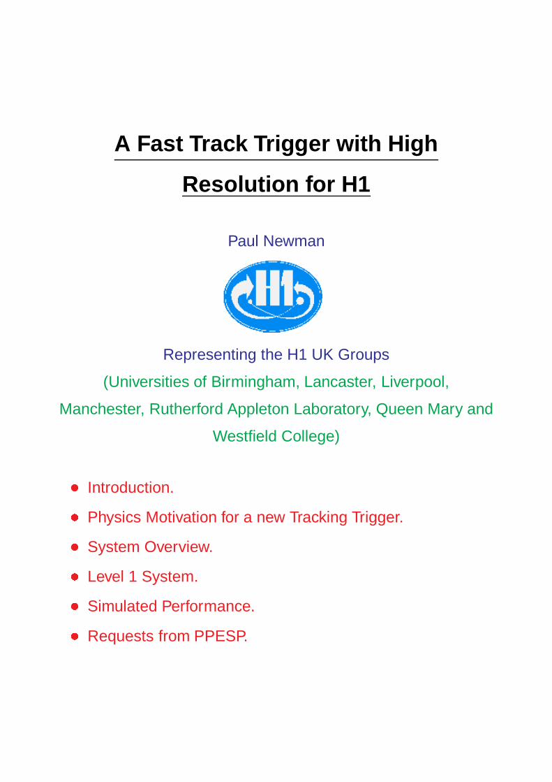
Trigger Rates after the HERA Upgrade
� HERA upgrade 2000-1 . . . factor� 5 increase in luminosity.
At Lmax
� 70 �b
�1
s
�1, rates of observable ep interactions:
Kinematic range Rate [Hz]
Q
2
<1 GeV2 1000
1< Q
2
<10 GeV2 40
10 GeV2< Q
2 4
� Max input rate to level 4 (filter farm) trigger� 100 Hz.
Without improved selectivity at earlier stages of trigger,
prescaling will be necessary:
Q
2 Present Prescale Resulting
Prescale after Upgrade Efficiency
0 1 1 0%
5 5 25 4%
40 2 10 10%
150 1 1 100%
Most Exclusive Final States at low Q2 subject to these
prescales

Example Physics Processes
Many measurements crucial to our understanding of QCD
dynamics / proton structure . . .
1) have low visible cross section.
2) do not contain high pt
final states for easy triggering.
3) display track based signatures.
1) Open charm physics: (D�
! D
0
�
slow
! K��
slow
)
� Direct xg
g(x
g
) via (?)g ! �
� Charm structure function F � 2
� Gluon distribution of photon, pomeron . . .
� Open beauty physics through b! decays.
0
10
20
-4 -3 -2 -1 00
10
20
-4 -3 -2 -1 0log xg
x gg(x
g)
H1 NLO
QCD fit to F2
D* (DIS)
D* (γp)
CTEQ4F3
µ2=25 GeV2
p
cγ( )
c
g
e e'
Proton gluon density
Stat. errors� 25%
from� 96 data.
Much better stats and
high pT
(D
�
) data needed
for detailed analysis!

Example Physics Processes
2) Vector meson production:
ψγ� p! V p calculable in pQCD?
� Novel parton dynamics?
� �, J= not well measured at high Q2, jtj
� Little data so far for �, �0, 0, � . . .
� Inelastic J= poorly understood.
3) High pT
Charged Particles
� High pt
charged particles almost always interesting . . .
e.g. W , Z (semi)-leptonic decays.
Heavy flavour semi-leptonic decays.
Isolated muons with missing pt
.
� FTT accurately measures track pT
at early stages of trigger.
4) Discovery Potential
� Exotic processes can show up as anomalous charged /
neutral final state yields . . .
QCD Instantons.
Centauro / Anti-centauro events.
Disoriented chiral condensate (Bjorken).
� FTT can be used in conjunction with calo jet trigger etc.

Example Physics Processes
1996 DATA ESTIMATED 97� 00 ESTIMATED 2001++
PROCESS 13 pb
�1
92 pb
�1 DELIVERED 600 pb
�1
DELIVERED (OPTIMISTIC!) DELIVERED
D
� in DIS (Q2
> 2 GeV
2) 583 4100 27000
D
� in DIS FROM b DECAY (9) (60) (420)
D
� in diffractive DIS (Q2
> 2 GeV
2 ) 11 80 510
D
� in p 788 5500 36000
D
� in p FROM b DECAY (13) (90) (600)
Elastic �0 ! �
+
�
� (Q2
> 30 GeV
2) 16 110 740
Quasi-elastic J= ! �
+
�
� (Q2
> 2 GeV
2) 156 1100 7200
Quasi-elastic J= ! e
+
e
� (Q2
> 2 GeV
2) 74 520 3400

Track Triggering in H1
� Present H1 track triggering . . .
Loose selection at L1 (DCr�) (Deadtime free 2:3 �s)
L4 refinements based on full track rec’n (800 �s)
� Proposed Fast Track Trigger (FTT) . . .
Decisions at L1 (2:3 �s), L2 (25 �s) and L3 (<�
100 �s)
DCr� FTT
number of DC layers 10 12
hit resolution 5 mm 500 �m
p
T
range >
�
400 MeV > 100 MeV
track multiplicity N
DCr�
/ N
tra ks
precise
p
t
resolution 2 loose thresholds �(1=p
T
) �
400, 800 MeV 0:05=GeV
z-information no yes
topological info. Limited, r� only. Detailed, 3D
invariant masses no yes
The FTT will . . .
� Generally improve H1 track triggering capabilities.
� Identify exclusive final states early enough to avoid
large prescales.
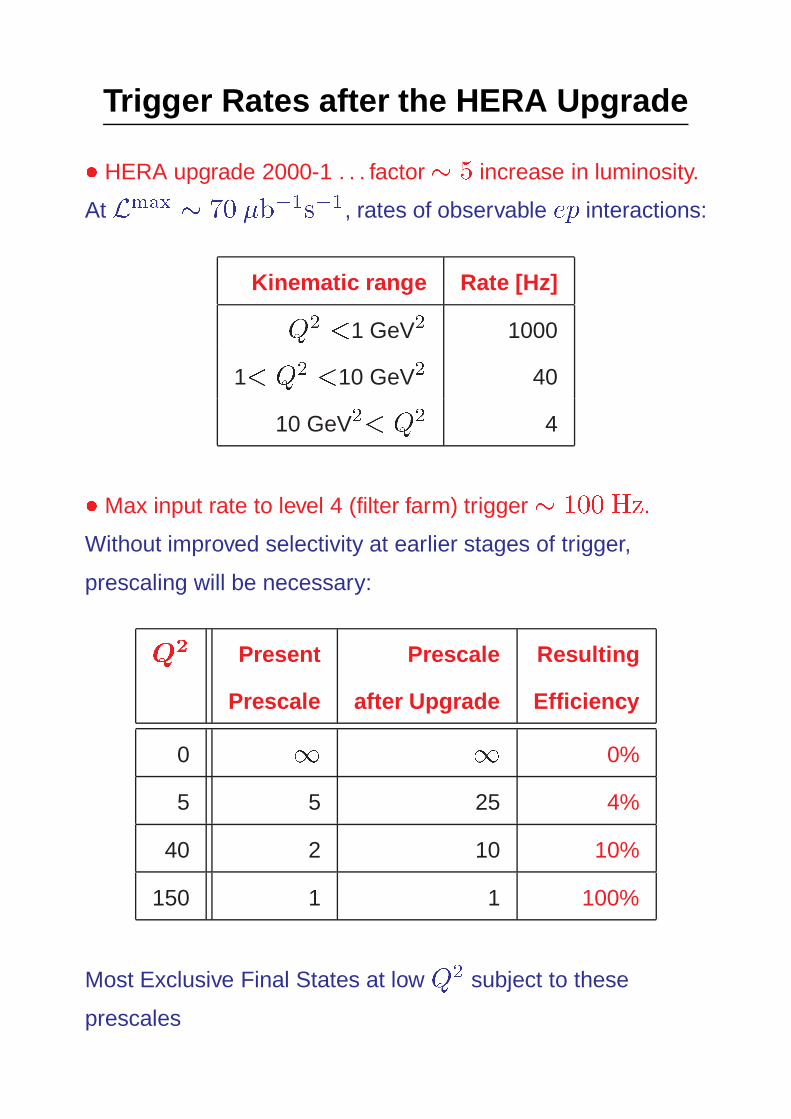
Principle of the Fast Track Trigger
H1 Central Jet Chambers:
CJC1 - 30 cells in �, 24 layers of sense wires in r
CJC2 - 60 cells in �, 32 layers of sense wires in r
Take signals from four groups of three layers, all cells.
e.g. CJC1: (3,5,7), (10,12,14), (18,20,22), CJC2: (4,6,8).
r-� Projection
CJC1 CJC2
Advances in integration and speed of electronics and rapidly
reducing costs allow . . .
� Detailed drift chamber analysis on-line.
� Identification of complex signatures from track
combinations at L1-3.

Specifications at L1-L3
L1 L2 L3
Latency 2:3 �s 25 �s
<
�
100 �s
Q� t analysis
Tasks Track Segment Event
Track segment linking. rec’n.
finding
Data Coarsely Tracks
for linked with precisely Combinations
Trigger track determined of Tracks
Decision segments 3-momenta
Basis of Tracks with Track pT
Trigger variable pT
multiplicity, Invariant
Decision thresholds, topology mass sums
multiplicity, sign? total Et
. . . D
�
�M . . .
H1-UK groups have taken responsibility for the L1 system.

Overview of L1 System
Pre-ampand
30 x 8 bitFADC
FPGA farmfor QT,
segmentfinding andprocessing
LVDS read-out to L2
I/O w
ith adjacent boardsand to L1 trigger
Control
Databetweenadjacentcardsin ring
To L1 trigger
From triggercontrol
To L2system
Ana
logu
e in
put f
rom
dau
ghte
r ca
rds
Crate controller / service module
Ring of sixFront-endmodules
Functionality:
� Analogue CJC signals taken from front of FADC cards.
� Preamp. and 30 8-bit FADCs digitize signals at 80 MHz.
� Q� t algorithm implemented on FPGAs
� Coarse/fine track segment finding done using CAM
functionality of the ”FPGA farm”
� Track segment data processed! merged pT
, �, z-info.

Data Flow Through L1 System
QT Analysis
kappa, philookup
merging kappa,phi,z-> 32 bit
FIFO
coarse 32 bitfine 128 bit shift register
+ subaddresses
pivot layer
t
t
(ref. BaBar)
(drift 1 mus)
(approx. 0.5 mus)
(approx. 0.1 mus)
(approx. 0.3 mus)
patern match (CAMs)- on fly- pivot layer
FrontEndhits
segments
track
∆ t=1-2ns
z coordinatedetermined bycharge division.
! coarse (20MHz) pT
=�
segments to L1 trigger
O(10
3
) valid masks
Precise (80MHz) pT
=�=z segments to L2 track linker
O(10
5
) valid masks
(80MHz)
(20MHz)
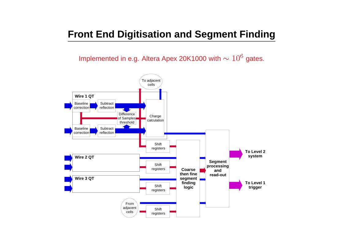
Front End Digitisation and Segment Finding
Implemented in e.g. Altera Apex 20K1000 with� 10
6 gates.
Baselinecorrection
Subtractreflection
Baselinecorrection
Subtractreflection
Differenceof Samplesthreshold
Chargecalculation
To adjacentcells
Shiftregisters
Shiftregisters
Wire 1 QT
Wire 2 QT
Shiftregisters
Wire 3 QT
Shiftregisters
Fromadjacent
cells
Coarsethen finesegmentfindinglogic
Segmentprocessing
andread-out
To Level 2system
To Level 1trigger

Finding Valid Masks for Trigger Groups
adja
cent
cel
ls
wires
cell boundaries
rightleft
track element
hit insertion
Track Segment Finding
� Masks defined in shift registers, corresponding to valid
track segments in 3 wires of a trigger layer.
� Entries in shift registers corresponding to left-right drift
space ambiguity.
� Adjacent cells analysed together to deal with tracks
crossing cell boundaries.
� Bunch crossing of origin can be identified where tracks
pass on either side of wires or cross cell boundaries.

Determination of �, pT
VERTEXEVENT
TRACKSEGMENT
r PLANE
Assumption of vertex inr-� plane allows �and p
T
determination.
Valid track segment masksconverted to (p
T
, �)values using Look Up Tables
Trigger Group Efficiency (εsingle hit=0.95)
00.10.20.30.40.50.60.70.80.9
1
0.08 0.1 0.12 0.14 0.16 0.18 0.2 0.22 0.24
radius=24cmradius=32cmradius=40cmradius=59cm
(a)
negatively charged particles
pt(q=-e) (GeV)
effi
cien
cy
00.10.20.30.40.50.60.70.80.9
1
0.08 0.1 0.12 0.14 0.16 0.18 0.2 0.22 0.24
radius=24cmradius=32cmradius=40cmradius=59cm
(b)
positively charged particles
pt(q=+e) (GeV)
effi
cien
cy
Each trigger groupis 3 CJC wires.
High efficiencydown top
T
� 100 MeV
in most cases.
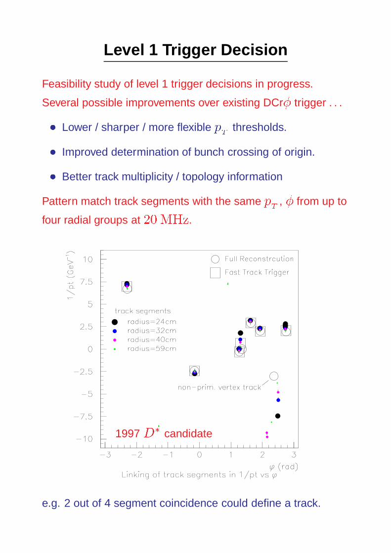
Level 1 Trigger Decision
Feasibility study of level 1 trigger decisions in progress.
Several possible improvements over existing DCr� trigger . . .
� Lower / sharper / more flexible pT
thresholds.
� Improved determination of bunch crossing of origin.
� Better track multiplicity / topology information
Pattern match track segments with the same pT
, � from up to
four radial groups at 20 MHz.
1997 D� candidate
e.g. 2 out of 4 segment coincidence could define a track.

Level 1 Trigger Viability
0
10
20
30
40
50
60
70
1 2 3 4 5
Number of reconstructed tracks
Eve
nts
First simulation studies promising . . .ElasticJ= ! �
+
�
�
Correct number of tracks
reconstructed by L1 trigger.
Significant improvement on DCr�
Bunch crossing of origin (�96 ns) determination . . .
0
10
20
30
40
50
60
70
80
-1 -0.5 0 0.5 1 1.5
Bunch Crossing relative to nominal
Eve
nts
0
20
40
60
80
100
-1 -0.5 0 0.5 1 1.5
Bunch Crossing relative to nominal
Eve
nts
20 MHz clock.
Elastic J= eventsD
�
! K�� events
p
T
� � track segment pattern matching could be realised
using CAMs at marginal hardware costs.
Crucial question will be time constraints

Level 2 Track Segment Linking
Level 2 track linking is performed by pattern matching track
segments with the same pT
, � from all four radial groups.
Achieved using CAMs
CAM
à 128words of32 bits
Inpu
t FIF
O
dirtyCAM
à 128words of32 bits
SRAM
Out
put F
IFO
Search Logic
!
from L1
! to DSP, thentrigger logic / L3
1. (pT
, �) vectors loaded into 1 CAM per radial group.
2. All track segments loaded into SRAM.
3. SRAM contents matched in (pT
, �) with each CAM.
4. Best match with� 2 coincidences defines track.
5. ‘Dirty’ CAM containing already linked segments vetoes
double counting.
6. Optimisation procedure in DSP.
Development at an advanced stage (DESY, ETH Zurich).

Level 3 System
� Tracks combined to search for complex final state
signatures (D�, J= , � . . . )
� L3 reject can be made anytime during� 800 �s detector
readout time.
� Early decision reduces deadtime, allowing more events to
be processed.
� With L3 decision after 100 �s, 500 Hz processing costs
5% deadtime.
Software selection to run on commercial processors . . .
� 2 PCs enough to trigger on wide range of processes.
Detailed work yet to begin.

FTT Resolution in p
T
, �, �
FTT level 1, 2 algorithms have been simulated . . .
Efficiencies, resolutions, robustness studied with real events.
Track resolutions in 1=pT
, �
(relative to full off-line reconstruction, using 1997 D� data) . . .
�(1=p
T
) � 0:05 GeV
�1
�(�) � 5 mrad
Reconstruction of Track �
� calculated from . . .
� z of hits from L1 FTT charge division [�(zhit
) � 6 m]
� z of vertex from L1 MWPC trigger [�(zvtx
) � 2:5 m]
(relative to full off-line reconstruction, using 1997 D� data) . . .
�(�) � 50 mrad
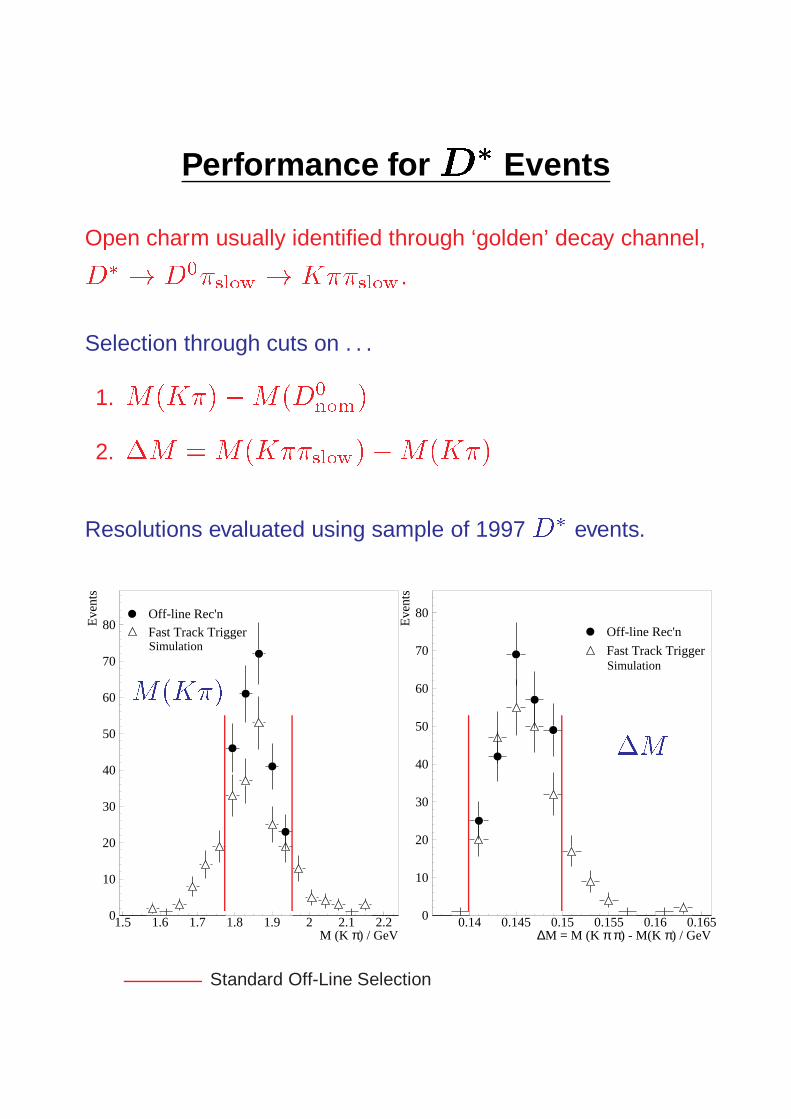
Performance for D
� Events
Open charm usually identified through ‘golden’ decay channel,
D
�
! D
0
�
slow
! K��
slow
.
Selection through cuts on . . .
1. M(K�)�M(D
0
nom
)
2. �M =M(K��
slow
)�M(K�)
Resolutions evaluated using sample of 1997 D� events.
0
10
20
30
40
50
60
70
80
1.5 1.6 1.7 1.8 1.9 2 2.1 2.2
Off-line Rec'nFast Track TriggerSimulation
M (K π) / GeV
Eve
nts
0
10
20
30
40
50
60
70
80
0.14 0.145 0.15 0.155 0.16 0.165
Off-line Rec'n
Fast Track TriggerSimulation
∆M = M (K π π) - M(K π) / GeV
Eve
nts
Standard Off-Line Selection
M(K�)
�M

Performance for D
� Events
D
� finding efficiency studied relative to off-line selection for
various cuts on D0 mass window and �M .
Trigger rates estimated for peak post upgrade luminosities by
extrapolation from current rates.
0
0.1
0.2
0.3
0.4
0.5
0.6
0.7
0.8
0.9
1
0.15 0.155 0.16 0.165 0.17
Cut on ∆M = M(K π π) - M(K π) / GeV
Eff
icie
ncy
Rel
ativ
e to
Off
-lin
e Se
lect
ion
Efficiency(left hand scale)
| M(K π) - M(D0)nom | < 300 MeV
| M(K π) - M(D0)nom | < 250 MeV
| M(K π) - M(D0)nom | < 200 MeV
Rate(right hand scale)
0
5
10
15
20
25
30
Est
imat
ed R
ate
/ Hz
80% efficiency achievable with <�
5 Hz peak rate.
Efficiencies� 5% higher for b! ! D
� .

Transverse Momentum Selectivity
Large rate reductions can be achieved for many physics
channels with pT
cuts at level 2.
e.g. �, J= , Z ! l
+
l
�, W ! �� . . .
Resolution ��
1
p
T
�
� 0:05 GeV
�1.
Fast Track Trigger
cut on track with highest pt (GeV)
redu
ctio
n fa
ctor
0
2
4
6
8
10
12
14
16
18
0 1 2 3 4 5 6 7 8 9 10

Estimated Trigger Efficiencies
trigger rates trigger
with FTT [Hz] efficiency [%]
Process L1 L2 L3 with FTT without
D� decay (DIS) 160 - 500 30 5 70 1
D� decay (e-tagged p) 120 - 500 25 4 60 1
�! �
+
�
� (DIS) 40 2.5 1 80 2
J/! ee,�� 50 20 1-3 12-60 1-3
�! ee, �� 50 5 0.5-2 12-60 1-3
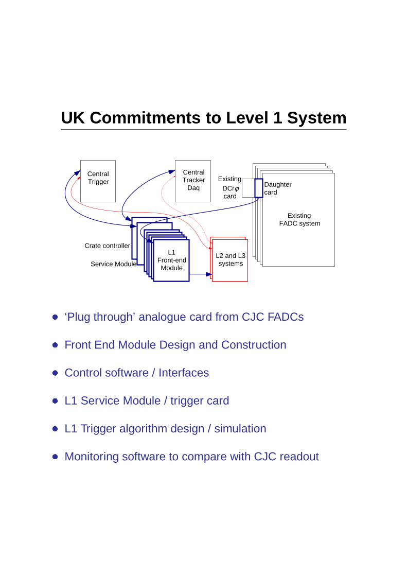
UK Commitments to Level 1 System
ExistingFADC system
CentralTracker
Daq
CentralTrigger
L1Front-endModule
Crate controller
Service Module
Daughtercard
ExistingDCrφcard
L2 and L3systems
� ‘Plug through’ analogue card from CJC FADCs
� Front End Module Design and Construction
� Control software / Interfaces
� L1 Service Module / trigger card
� L1 Trigger algorithm design / simulation
� Monitoring software to compare with CJC readout

Costing of Level 1 System
ITEM COST ($) EFFORT (Staff Years) SOURCE OF EFFORT
Analogue Plug-through Card (150) 30k 0.25 + 0.5 RAL + Manchester
Front End Modules (30) 135k 3 + 1 RAL + RAL PPD
Coding segment finding algorithm 2 DESY + Zurich
Crate control processor (2) 10k
Control software and Interfaces 0.75 + 0.25 RAL + Manchester
Service Module / trigger card (2) 10k 1 Birmingham + Manchester
Compact PCI Crates (2) 20k
Cabling 10k
Workstation and Interfaces 5k
Trigger algorithms / simulation 2.5 Birmingham + Zurich
Monitoring Software 1.25 UK Universities
Total (incl. VAT @ 17.5 %) 260k 4 + 8.5
Items in red are requests from PPESP.
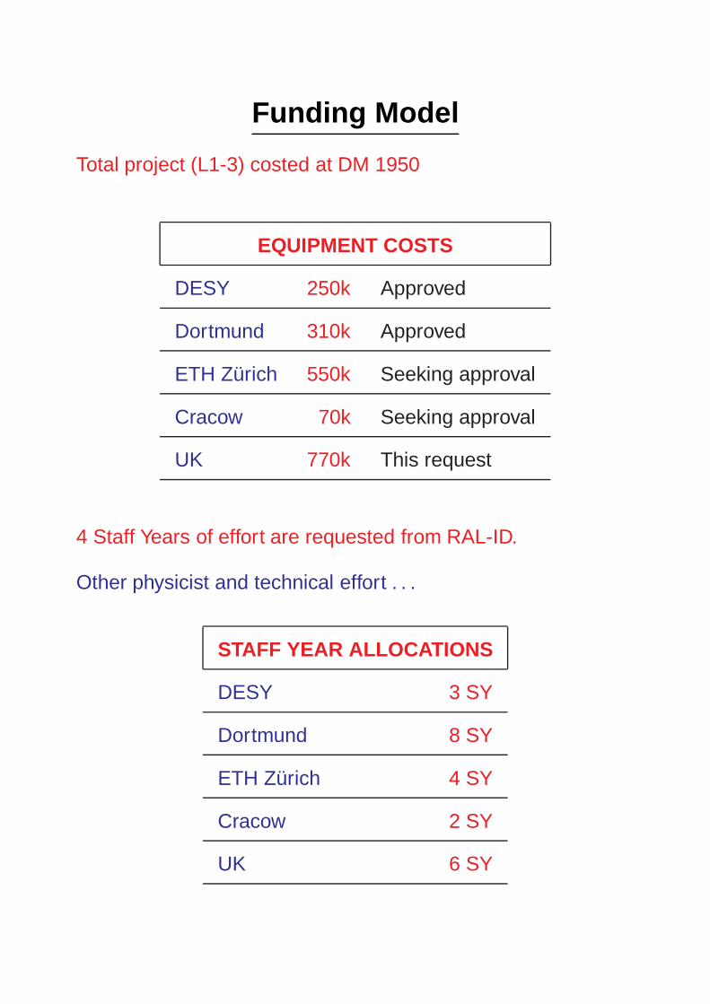
Funding Model
Total project (L1-3) costed at DM 1950
EQUIPMENT COSTS
DESY 250k Approved
Dortmund 310k Approved
ETH Zurich 550k Seeking approval
Cracow 70k Seeking approval
UK 770k This request
4 Staff Years of effort are requested from RAL-ID.
Other physicist and technical effort . . .
STAFF YEAR ALLOCATIONS
DESY 3 SY
Dortmund 8 SY
ETH Zurich 4 SY
Cracow 2 SY
UK 6 SY

Time Schedules for Level 1 System
Fully commissioned system by end 2001 gives� 5 years run-time.
FRONT END MODULE
Preliminary design report now - 03/00
First design 03/00 - 06/00
Board layout 06/00 - 12/00
Prototype manufacture 12/00 - 01/01
Debug / testing prototype 01/01 - 03/01
Installation of prototype at H1 before 03/01 �
Redesign and layout 04/01 - 06/01
Main production 06/01 - 12/01
� end of HERA shutdown is planned for 03/01
OTHER MILESTONES
Segment finding algorithm Finalised before 04/00
Segment finding programmed on FPGAs before 03/01 �
L1 trigger viability studies now - 03/00
L1 trigger algorithm design 03/00 - 11/00
Service Module design, build, test before 02/01
Installation of Service Module before 03/01 �
Installation of Analogue Plug through cards before 03/01 �
First version of Control Software before 03/01 �
Full System Operational before 12/01
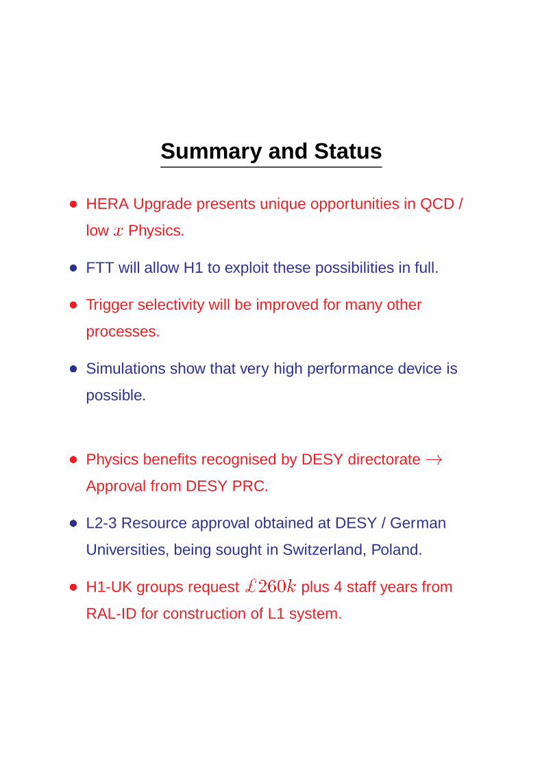
Summary and Status
� HERA Upgrade presents unique opportunities in QCD /
low x Physics.
� FTT will allow H1 to exploit these possibilities in full.
� Trigger selectivity will be improved for many other
processes.
� Simulations show that very high performance device is
possible.
� Physics benefits recognised by DESY directorate!
Approval from DESY PRC.
� L2-3 Resource approval obtained at DESY / German
Universities, being sought in Switzerland, Poland.
� H1-UK groups request $260k plus 4 staff years from
RAL-ID for construction of L1 system.