A family of network topologies with multiple loops and logarithmic diameter
18
ELSEWER Parallel Computing 22 (1997) 2047-2064 PARALLEL COMPUTING A family of network topologies with multiple loops and logarithmic diameter Srabani Sen Gupta a, Rajib K. Das a, Krishnendu Mukhopadhyaya b, Bhabani P. Sinha aq* a Electronics Unit, Indian Statistical Institute, 203, B.T. Road, Calcutta 700 035, India b Deparhnent of Mathematics, Jadaupur University, Calcutta 700 032, India Received 6 April 1995; revised 20 April 19% Abstract A new family of network topologies containing multiple loops is discussed in this paper. In the proposed structure, N processors are interconnected to form a graph G(m, N), m > 3, where m is a parameter of the graph such that N is an even multiple of m and (m - 1) X 2’t”- ‘)/21+’ < N Q m X 21m/21+‘. The graph G(m, N) is hamiltonian with an average node degree (3 + I/m), when m is even and exactly 3 when m is odd. Whereas, the maximum node degree is 4. The diameter of G(m, N) is upper bounded by 111 m/8] + 1. A point to point routing algorithm has been presented. Implementation of ASCEND/DESCEND algorithms in O(m) time has heen discussed. It has heen shown that in case of a single node failure, the diameter increases by at most 6. Keywords: Ascend and Descend algorithms; Diameter; Network topology; Routing; Redundant binary representation 1. Introduction Designing efficient schemes for interconnecting a large number of computing ele- ments to form an integrated multiprocessor system has become an important area of recent research. Different network topologies exists in the literature [9,1] for this purpose. In designing a topology, low number of links per node (to reduce the cost of interconnection), small internode distances, large number of alternative paths between every pair of nodes (for improving the fault tolerance), etc. are some of the key * Corresponding author. Email: [email protected]. 0167-8191/97/$17.00 0 1997 Elsevier Science B.V. All rights reserved fff SO167-8191(97)00067-1
Transcript of A family of network topologies with multiple loops and logarithmic diameter
ELSEWER Parallel Computing 22 (1997) 2047-2064
PARALLEL COMPUTING
A family of network topologies with multiple loops and logarithmic diameter
Srabani Sen Gupta a, Rajib K. Das a, Krishnendu Mukhopadhyaya b, Bhabani P. Sinha aq*
a Electronics Unit, Indian Statistical Institute, 203, B.T. Road, Calcutta 700 035, India
b Deparhnent of Mathematics, Jadaupur University, Calcutta 700 032, India
Received 6 April 1995; revised 20 April 19%
Abstract
A new family of network topologies containing multiple loops is discussed in this paper. In the proposed structure, N processors are interconnected to form a graph G(m, N), m > 3, where m is a parameter of the graph such that N is an even multiple of m and (m - 1) X 2’t”- ‘)/21+’ < N Q
m X 21m/21+‘. The graph G(m, N) is hamiltonian with an average node degree (3 + I/m), when m is even and exactly 3 when m is odd. Whereas, the maximum node degree is 4. The diameter of G(m, N) is upper bounded by 111 m/8] + 1. A point to point routing algorithm has been presented. Implementation of ASCEND/DESCEND algorithms in O(m) time has heen discussed. It has heen shown that in case of a single node failure, the diameter increases by at most 6.
Keywords: Ascend and Descend algorithms; Diameter; Network topology; Routing; Redundant binary
representation
1. Introduction
Designing efficient schemes for interconnecting a large number of computing ele- ments to form an integrated multiprocessor system has become an important area of recent research. Different network topologies exists in the literature [9,1] for this purpose. In designing a topology, low number of links per node (to reduce the cost of interconnection), small internode distances, large number of alternative paths between every pair of nodes (for improving the fault tolerance), etc. are some of the key
* Corresponding author. Email: [email protected].
0167-8191/97/$17.00 0 1997 Elsevier Science B.V. All rights reserved
fff SO167-8191(97)00067-1
2048 S. Sen Guptu et al./ Purullel Computing 22 (1997) 2047-2064
considerations. Mesh, ring, chordal ring, tree, hypercube, cube-connected cycle, etc. are a few among the popular interconnection topologies used for parallel and distributed systems.
The ring topology is widely used due to its structural symmetry and simplicity. The routing algorithm in a ring is very simple. But a ring with N nodes, has the diameter [N/2], leading to a large communication delay. The diameter can, however, be reduced if additional links are introduced within a ring. Some of the topologies resulting from such modifications are chordal ring [3], distributed loop network [4,6], etc., which have been widely studied in the literature. In a chordal ring, the degree of every node is 3, while the diameter is O(fi), N being the total number of nodes in the graph. In a distributed loop network the lower bound on the diameter is (dm - 1)/2, with the degree of every node increased to 4.
We propose here a new family of network topologies, by adding a few extra links over the ring. A topology in this family has nodes with degrees only 2, 3, and 4 (average node degree is less than or equal to 3.25) and has the diameter upper bounded by 111 m/8] + 1, where m is a parameter of the graph such that m > 3, N is an even multiple of m and (m - 1) X 21(m-‘)/21+’ <NGmX 21”‘/*1+‘. This shows that the diameter of the topology is O(log N). In respect of diameter, this topology is thus superior to both the chordal ring and distributed loop network. The total number of links used in this network is less than that in a distributed loop network and is no more than hth of that in a chordal ring. An algorithm for point to point routing has also been presented. The Ascend and Descend types of algorithms [12] can be very efficiently implemented on this topology. Moreover, the successive values of N, for which the proposed topology can be defined, are at an interval of 2m < 4 log N. That is, if N and N’, are two successive values of the total number of nodes with N’ > N, then N’ - N = 2m. This may be contrasted with other fixed degree topologies having O(log N) diameter, e.g., Moebius graph [ 101, de Bruijn graph [8], cube-connected cycle [12], etc., for which the successive values of N are at much larger intervals. For all such graphs, N’ is at least 2N. The proposed network graph is hamiltonian and in case of a single node failure, the diameter may increase at most by 6.
2. Description of the topology
We describe the topology in terms of a graph G(m, N), having the following characteristics:
(a) N is the total number of nodes in the graph. Let the nodes be numbered as 0, l,..., N- 1.
(b) m is a parameter of the graph such that m > 3. (c) N is an even multiple of m such that N = 2k X m, for some positive integer k. (d) (m _ 1) X 21’“- 1)/21+ I <N < m X 21m/*l+ I.
(e) The nodes are connected by the following three types of edges (all operations below are treated under modulo N, unless otherwise mentioned):
(1) The node i is connected to the nodes (i + 1) and (i - 1). Thus the nodes are connected in the form of a cycle. We call these edges as c-edges (cyclic edges).
S. Sen Gupta et ul./Purullel Computing 22 (199712047-2064 2049
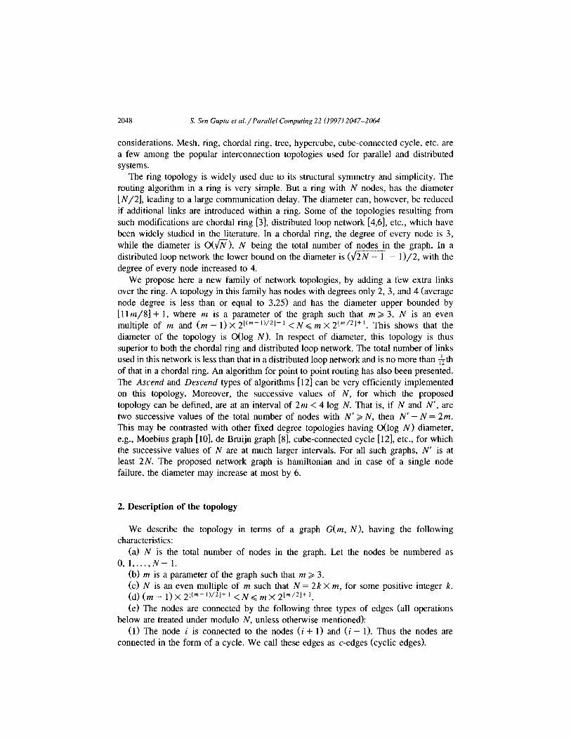
(a) For m = 8
0 1 2 3 4 5 6 7 8 9 10 11
I /i = A = A ; A = A = I d fh fh2 +ho *hi *hs d
(b) For m = 11
Fig. 1. Hop distribution in sector 0.
(2) For 0 G i G 2 k - 1, the node i. m is connected to the diametrically opposite node (i.m + N/2). We call these edges as d-edges (diagonal edges).
After introducing d-edges, there are 2k number of nodes in the network, which are of degree 3. These degree 3 nodes divide the cycle, formed in (l), into 2k parts. We call each of these parts as a sector of length m. The sector j consists of the nodes, {j.m, j.m+ 1, j.m+2 ,..., (j+ l>m), O<j<(2k- 1).
(3) Nodes in different sectors are interconnected by a third type of edges, called as hops or h-edges, as described below.
Starting from the node j.m + 1, in sector j, 0 G j G 2 k - 1, h-edges are introduced at every alternate node (there are [m/2] such nodes in every sector). These connections are done by the following ways depending on the value of m. Let [m/2] - 1 = r.
(i) The node j.m + 2i + 1 is connected to the nodes [( j.m + 2i + 1) rfr m X 2r-2i], i=O, 1, 2,... , [r/2]. These hops are denoted by h + Cr- 2 i) respectively.
(iia) If r is even then the node j.m + [m/2] + 2i is connected to the nodes [( j.m + [m/2] + 2i) + m X 22’-’ ],i = 1, 2,. . . , r/2. These hops are denoted by h + 2i respectively.
Fig. 2. The proposed graph G(5,40).
2050 S. Sen Gupru er al./ Purullel Computing 22 (1997) 2047-2044
(iib) If r is odd then the node j.m + lm/2] + 2i + 1 is connected to the nodes [(j.m+[m/2]+2i+1)+mX22’],bythehops h?,;, i=O, l,...,[r/2].
An example of the hop distribution in sector 0 of the proposed topology when m = 8 and m = 11 is given in Fig. 1. Fig. 2 shows the complete connection pattern in G(5, 40). It is to be noted here that the largest hop originated from a sector, is /z,~,~,- ,. A hop hi will be referred to as even (odd) if i is even (odd). The connection pattern shows that even and odd hops originate from different halves of a sector. The two hops connecting a vertex v to v + m.2’ and v - m.2’ will be referred to as +h, and -h, respectively.
Average node degree of this graph is 3 + l/m, when m is even and exactly 3 when m is odd. Thus the total number of edges in the graph is asymptotically N 1.5 N.
Remark. If all the nodes in each sector (that is, the nodes jm, jm + 1,. . . , (j + 1)m - 1 in sector j, Vj, 0 =S j < N/m) of G( m, N) are coalesced to form a single node repre- senting the whole sector then the resultant graph will be a supergraph of the circulant G(N/m, f 1, +2, + 22, f 23 ,..., 21”sCN/“‘)l- ‘) [5,7] (or recursive circulant G( N, d) for d = 2 Ill]). Only in a special case, when N = m.2Lm’21t’ the graph obtained by coalescing the nodes in each sector of G(m, N) will be identical to G(N/m, + 1, + 2, + 22, &- 23,. . . ,2log(N’+ ’ ). However, because of the typical degree distribution of the nodes in a sector, the extension of the results regarding diameter, routing, etc. of circulant graphs [5] or recursive circulant graphs [ 111 can not be directly extended to G(m, N) and then need a separate treatment as given in the following sections. Moreover, the node degree (approximately equal to log, N) in the recursive circulant graph increases with the total number of nodes N. In the proposed topology the average node degree is approximately equal to 3 and the maximum node degree is 4. In this regard the proposed topology is more cost effective.
3. Diameter of the network
In this section, we find an upper bound on the diameter D of the graph G(m, N). To start with, we discuss about a restricted redundant binary number system to represent a node of the graph.
3.1. Restricted redundant binary representation
Definition. A redundant binary representation of a number K = k,- , k,- 2 . . . k,, is one in which each digit k,, 0 < i < r - 1, is an element of {0, 1, i] and K = Cjzd2’k,.
Naturally, K does not have a unique representation in redundant binary system. For example, the binary number 0111011 has the equivalent representations 1OOilOi and 1OOOiOi in redundant binary.
Definition. A redundant binary representation, in which there is at least one zero bit in between two non-zero bits, will be termed as a Restricted Redundant Binary (RRB) representation.
S. Sen Gupta et al./ Parallel Computing 22 (1997) 2047-2064 205 1
Example 1. In the above example, lOOO?Oi is the RRB representation of the binary string 0111011.
Remark. This RRB representation is similar to the canonical signed digit (CSD) representation [2,13] of a positive integer for the radix 2. It follows from the results in [ 131 that the CSD (as well as RRB) representation of a number is unique and it can be computed sequentially by scanning the binary representation of the number from right to left. Thus, the RRB representation of a number N can be computed sequentially in 0 (log N) time.
Lemma 1. In the RRB representation of N, the number of non-zero bits can be at most
[(rlog Nl + 1)/21.
Lemma 2. In the RRB representation, the largest number M that can be obtained using b number of bits is given by
M= $(2b- l), if b is even,
f(2’- 1) + f, otherwise.
Proof. It is clear that for the largest number, every alternate bit starting from the most significant bit will be 1.
If b is even, then
L=26-‘+26-3+ . . . +2=$b-l).
Otherwise,
,y = 2b- ’ + 2b-3 + . . . +2O=f(2b- 1) +f. q
Let wX be the total number non-zero bits in the RRB representation of a number X. Further suppose that w,’ and w,” be the number of non-zero bits corresponding to the even and odd powers (“0” is excluded) of 2 respectively, in the RRB representation of x.
Example 2. For x = lOOiOiO1, W, = 4, w,’ = 2 and w,” = 1.
It is clear that when x is odd, w, = w,’ + w,” + 1, otherwise w\- = w,’ + w,“.
3.2. Upper bound on the diameter To find the diameter it is enough to consider the paths from a node s in sector 0, to a
node d < N/2, since all sectors look alike. Let d belong to the sector 6, 0 G 6 < [N/2m]. Starting from s, we use hops to move across different sectors. But to avail a hop we may need to traverse some c-edges. With a view to minimizing the total walk along the c-edges we would take either odd hops or even hops (depending on the value of s and d) which emanate from only one half of every sector. h, may be included in both the cases. Since accessing h, is equivalent to accessing h,- , twice, km/21 - 1 2 I >, 1, it is always possible to get such a collection of hops. The method how we select the hops to reach sector 6 starting from sector 0 is discussed below.
2052 S. Sen Guptu et al./ Parallel Computing 22 (1997) 2047-2064
First we find the RRB representation of the sector difference S (since the source is 0 here). The set of hops corresponding to the non-zero bits of this representation will be sufficient to cover these 6 sectors. Without loss of generality, let us assume that PV~ > ~8’. Therefore, it is wise to convert odd hops into even hops. In that case, the required number of hops will be w; + 2w,” instead of wt + wi. Now, let us try to estimate a bound on this number.
Case 1: 0 < d <N/4, i.e., 0 < 6 < [N/4m]. As 0 < 6 < [N/4mj, the number of bits required for RRB representation of 6 is
lm/21. For odd S, the least significant bit (lsb) in RRB representation of 6 is non-zero and
hence the second lsb is 0. Among the remaining [m/2] - 2 bits the number of non-zero bits will be at most [(I m/2] - 2)/2] = [(m - 2)/4J, by Lemma 1.
Thus, wl + wi = [Cm - 2)/41. After conversion, we need at most 2w$’ + w: + 1 number of hops. Now, 2w,” + wi + 1 G l$( ~8’ + w,‘>j + 1 < [$1( m - 2)/4]1 + 1. Thus the maximum number of hops required to reach sector S (using either even or odd hops along with some fh,) is L~(l(m - 2)/41)1 + 1.
For even 6, w; + wl = ws G [(lm/2J - 1)/2] = [m/4]. Therefore, when we need any conversion, the number of hops required is at most l$([m/4J)J.
Hence, the maximum number of hops required to reach sector 6, under the restriction that either even or odd hops (ha may be included in both the cases) can be used, is
when mmod8isOor 1,
+ 1, otherwise.
Case 2: [N/4m] < 6 < [N/2m]. To reach this part of our network, we may utilize diagonal edges. But if we include a
diagonal edge in our path, we would not use any +/z,,,,,~,-, hop. From sector 0, if we use a d-edge we will reach the boundary of the sectors 1 N/2m].
From there we have to cover a distance of j sectors (in backward direction) to reach sector S, where j = [N/2mj - 6. To traverse this distance we would not use hops fh,,,, _ ,. Here, by Lemma 2 we have, 0 G j< 3(21m/21-’ - 1) + f, which implies, [N/2mj - f(21m’21 - 1) G S < [N/2ml. For such a 6, the maximum number of hops required to reach the sector 6 can be enumerated as we have done in case 1. If B, represents this bound (including the diagonal edge), then
B = [~(~~])]+l, whenmmod8is2or3,
* I:( [:J - I)] +2, otherwise.
Now, we are left with the case when [N/4m] < 6 < 1 N/2mj - f(21m’*’ - 1) - 1. This range is totally contained in the range 0 < 6 < f(21mi21 - 1). Thus in this case, the
S. Sen Guptu et ul./Parallel Computing 22 (1997) 2047-2064 2053
number of hops required to reach the destination sector 6 is same as the bound obtained in case 1.
Hence for 0 6 6 G [N/2m], the number of hops required to reach sector 6, is at most max (B,, B2). It can be easily verified that max(B,, B2) is always B, Vm.
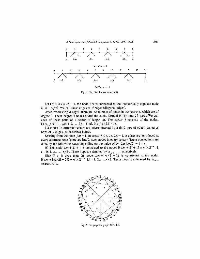
So far we have identified the appropriate hops required to reach the destination sector and have also enumerated a bound on the number of hops. Now, we would find a specific order in which these hops are to be availed so that the walk along the cycle will be small enough to minimize the total path length. Let us introduce the following notations first.
(1) xi denotes the node in the sector j, from which hops of type 0 are originated. Thus xj divides the sector j into two halves. Even and odd hops are emanated from these two halves.
(2)By[a,b]wemeanthesetofthenodesa,a+1,a+2,...,b. (3) Let H, be the set of hops of either even or odd types, required to reach sector 6.
Suppose 1 H, I = p. Let ~1, u;, . . . , uf be the nodes in sector j such that the hops in H, originate from these nodes and U) < u; < . . . < UP. Again, we call [u), UPI as the range of H, in sector j.
(4) Let the projection of d onto sec_tor j be a node aj in sector j, which is related to d bytheequation d=(6-j)xm+d,.
It is clear that to use the hops in H, (some of which may be repeated in the actual path), Vr, 1 G r Q p, we must traverse through UT at least once for some sector j, 0 G j ZG 2 k - 1. Now, counting the number of c-edges involved in this traversal can be equivalently mapped to the problem of counting the number of c-edges required to reach & starting from s, with the restriction that any one of (~6, I&- ,} is traversed at least once. We will now show that by appropriately choosing the order of the hops, this
I- Sector - 0 .------+
ZZk-1 u* Zk-1 u*,,-, 0 s 50 & do UP,J 7n
..-..-..-..-.. ..-..-..-..- c_b..---m.-+
---
(a) Traversal 1
+----- Sector - 0 ~4
XZk-I u’2k-1 up2k-,
(b) Traversal 2
Fig. 3. Traversal 1 and Traversal 2.
2054 S. Sen Gupta et al./Parallel Computing 22 (1997) 2047-2064
number can always be made less than or equal to m, by using at most one additional hop of type 0.
Without loss of generality let us assume that s < ;I,. Case 1: s and d, are in the different halves of the sector 0. Let us consider the
following two subcases separately: Subcuse la: [s, &]n[t& uOp]= $3. In this case either [u;, u,P]C[d, + 1, m] or
l& uOp1 c [O, s - 11. Suppose, [uh, u,$‘] L [do + 1, ml. Consider the situation in Fig. 3. For s + d, < m, use of the hops in H, requires the traversal from s to xZk-, using
c-edges, from xZk- , to x0 using an additional hop h, and then from x0 to do using c-edges. Hence, the number of edges other than those in H, is s + ]m/2] + 1 + da - [m/2] = s + d, + 1. We call this traversal traversal-l. The maximum number of edges covered in this traversal is at most m.
For s + d, > m, the required traversal is from s to ~0” and from u{ to &, using c-edges only, as shown in Fig. 3(b). Thus the number of edges other than those in H,, is
UO P-s+z4{-do<2m-(s+&)<m.
We call this traversal traversal-2. For [u;, uOp] c [O, s - 11, it can similarly be shown that the number of additional
edges required is at most m. Subcase lb: [s, ;i,] TV [u;, u,$] z @. If [u;, uOp] is totally contained in [s, d,L then
the required path is direct from s to zo, using c-edges and the path length is d, - s. Otherwise, it can be tackled in a similar way as we have done in subcase la. In both the situations the number of edges other than those in H,, will be at most m.
Case 2: s and & are in the same half of the sector. This case can also be treated in a similar fashion.
Remark. It is to be noted here that in case 2 a different approach will give us paths of smaller lengths. In this case we will use both even and odd types of hops corresponding to the RRB representation of 8, except those whose origins correspond to the points in [s + 1, & - 11. We will replace each of these hops in [s + 1, d, - l] by exactly two hops of smaller length. The details are given in [ 141. The length of these paths are at most [5m/4] + 2.
Combining all the above results, the length i, of the longest path between any two nodes is given by
i= [q([yj)j +l+m, when mmod8=2or3,
I [:(1:] -l)] +2+m, otherwise.
A little algebraic manipulation yields the following result.
Theorem 1. The diameter D of the graph G(m, N) is given by D < i < 111 m/81 + 1 if m mod 8 is 2, 4 or 5. Otherwise, D < 111 m/81.
S. Sen Guptu et al./Parallel Computing 22 (1997) 2047-2064 2055
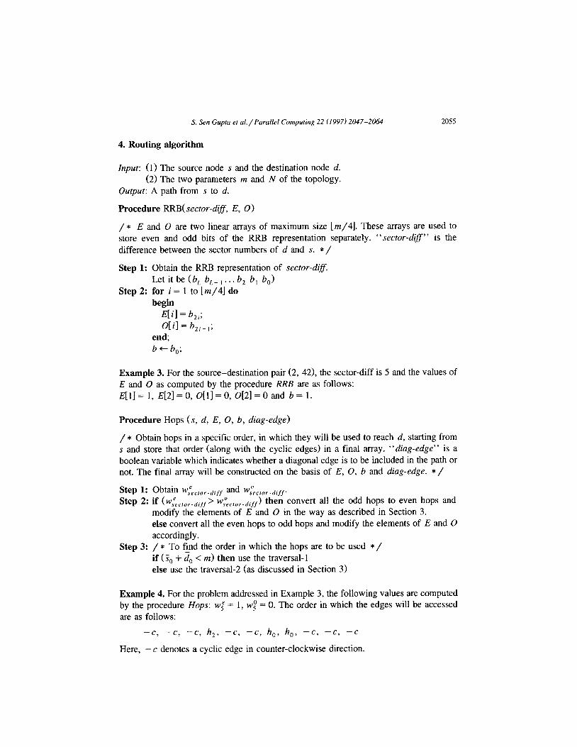
4. Routing algorithm
Input: (1) The source node s and the destination node d. (2) The two parameters m and N of the topology.
Output: A path from s to d.
Procedure RRB( sector-diff, E, 0)
/ * E and 0 are two linear arrays of maximum size [m/4]. These arrays are used to store even and odd bits of the RRB representation separately. “sector-diff” is the difference between the sector numbers of d and s. */
Step 1: Obtain the RRB representation of sector-difS. Let it be (b, b,- , . . . b, b, b,)
Step 2: for i = 1 to [m/4] do begin
E[ i] = bli; O[il= b,,- ,;
end; b+-6,;
Example 3. For the source-destination pair (2, 42) the sector-diff is 5 and the values of E and 0 as computed by the procedure RRB are as follows: E[l]= 1, E[2]=0, O[l]=O, 0[2]=0 and b= 1.
Procedure Hops (s, d, E, 0, b, diag-edge)
/ * Obtain hops in a specific order, in which they will be used to reach d, starting from s and store that order (along with the cyclic edges) in a final array. “diag-edge” is a boolean variable which indicates whether a diagonal edge is to be included in the path or not. The final array will be constructed on the basis of E, 0, b and diag-edge. * /
Step 1: Obtain W,P,,,or.diff and wsO,,,,,.difp
Step 2: if W~cror-drfp w&,or-diff ) then convert all the odd hops to even hops and modify the elements of E and 0 in the way as described in Section 3. else convert all the even hops to odd hops and modify the elements of E and 0 accordingly.
Step 3: / * To find the order in which the hops are to be used * / if (S, + & < m> then use the traversal-l else use the traversal-2 (as discussed in Section 3)
Example 4. For the problem addressed in Example 3, the following values are computed by the procedure Hops: w; = 1, wt = 0. The order in which the edges will be accessed are as follows:
-c, -c, -c, h,, -cc, -c, h,, h,, -c, -c, -c
Here, - c denotes a cyclic edge in counter-clockwise direction.
2056 S. Sen Cuptu et cd./ Parallel Computing 22 (1997) 2047-2064
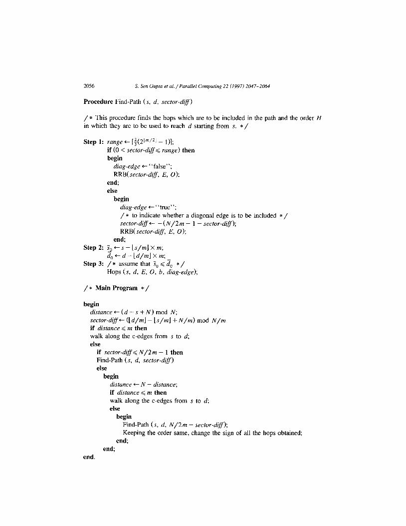
Procedure Find-Path (s, d, sector-dz#>
/ * This procedure finds the hops which are to be included in the path and the order H in which they are to be used to reach d starting from S. */
Step 1: range + [3(2Lm/*l - l)]; if (0 < sector-difS< range) then begin
diag-edge + “false”; RRB( sector-diff, E, 0);
end; else
begin diag-edge + “true”; / * to indicate whether a diagonal edge is to be included * / sector-diff +- - (N/2 m - 1 - sector-diSf); RRB( sector-diff, E, 0);
end; Step2: Sg+~-(s/mjxm;
d,+d-[d/m]xm; Step 3: / * assume that S, G ;S, */
Hops (s, d, E, 0, b, diag-edge);
/ * Main Program * /
begin distance + (d - s + N) mod N; sector-difS+ (1 d/ml - 1 s/ml + N/m) mod N/m if distance < m then walk along the c-edges from s to d; else
if sector-difl< N/2m - 1 then Find-Path (s, d, sector-dig) else
begin distance + N - distance; if distance < m then walk along the c-edges from s to d; else
begin Find-Path (s, d, N/2m - sector-dzy); Keeping the order same, change the sign of all the hops obtained;
end; end;
end.
S. Sen Gupm et al./ Parallel Computing 22 (1997) 2047-2064 2057
Example 5. According to the above algorithm, the following two paths are computed for the source destination pair (2, 42) and (13, 81) in G(8, 256).
Path from 2 to 42: 2+ 1+0+255+31 +30-+29-+37+45-+44-+43+42 Pathfrom13to81: 13+21-+20+19-+18+17+81
It can be verified that execution of the above algorithm requires O(log N) steps. The path is computed once for all at the source node in terms of the hop types taken in order and attached to the transmitted message. As there are m different types of hops (including both positive and negative), log m bits are needed to designate each hop. Hence, the total number of bits required to specify a path is O(m log m) = O(log N log log N).
5. Fault diameter
It is clear that the graph is biconnected. To find the diameter in presence of a single faulty node, we proceed as follows.
Let P be the path between two nodes s and d, obtained by the method discussed in section 3 with the path length L(P) < 111 m/8] + 1. In presence of a single faulty node, if the faulty node f lies on the path P, then there may be two possible cases: (A) the faulty node lies on a sector other than the sector 0 and the destination sector, (B) the faulty node is in the destination sector. The case for the faulty node lying in sector 0 can be treated in the same way as case B.
Case A. Let h, and h, (q < r) be two consecutive hops to be accessed in the path P and suppose while traversing along P, we enter the sector j by using the hop h, and leave that sector by using the hop h,. Let uy and U, be the respective nodes in sector j from where h, and h, originate.
The fault would affect the path if any one of the following occurs: Case 1: The node U, itself is faulty. Case 2: The node u, is a live node but the hop h, would take us to such a node
which is faulty. Case 3: An intermediate node within the range [ uq, ur] is faulty. We do not consider the case when the node uy is faulty. Because in that case, the
situation will be identical to the case 2 above for the sector from which we enter sector j. We consider below each of these cases separately.
Case 1. Instead of using a hop h,, we can use four hops of type (r - 2). Thus, in this case the path length would be increased by three. Therefore, the path length would be at most L( PI + 3 < i + 3.
Case 2. In this situation, we replace h, by the hops I-h,, -h,, -h,, hr+2} to bypass the fault. If h, is used twice in P, then we repiace those hops by {6(-h,), 2h,+2). Thus the path length could be at most L(P) + 6 < L + 6.
Case 3. We consider two subcases. Subcase 3a: The faulty node is of degree 2. Let U, and u,+~ be the two neighbors of
the faulty node f, and Iflh, and fh,+2 be the hops originated from these two nodes
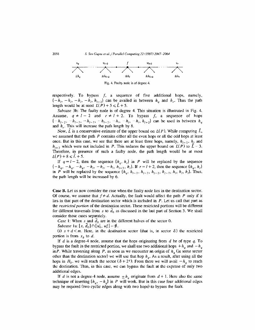
2058 S. Sen Gupta et al./ Purullel Computing 22 (1997) 2047-2064
f h, *h-z fh fh+z
Fig. 4. Faulty node is of degree 4.
fh,
respectively. To bypass f, a sequence of five additional hops, namely, I-h,, -h,, -h,, -h,, h,+J can be availed in between h, and h,. Thus the path length would be at most L( P) + 5 G i + 5.
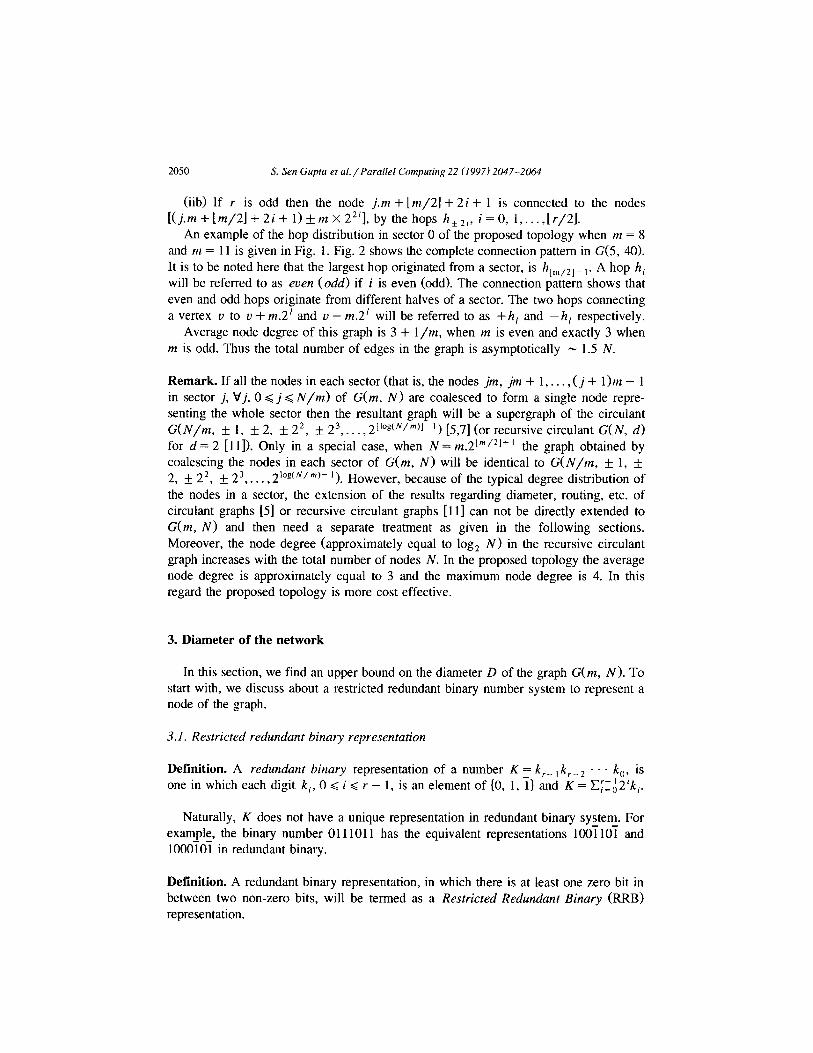
S&case 3b: The faulty node is of degree 4. This situation is illustrated in Fig. 4. Assume, q # 1 - 2 and r # 1 + 2. To bypass f, a sequence of hops
t-h,-,, -A,-,, -A,-2, -h,-,, -h,, -h,, -h,, h,,,) can be used in between h, and h,. This will increase the path length by 8.
Now, i is a conservative estimate of the upper bound on L(P). While computing i, we assumed that the path P contains either all the even hops or all the odd hops at least once. But in this case, we see that there are at least three hops, namely, h,- 2, h,l and h ,+ 2 which were not included in P. This reduces the upper bound on L(P) to L - 3. Therefore, in presence of such a faulty node, the path length would be at most L(P)+sd+5.
If q = 1 - 2, then the sequence (h,, h,} in P will be replaced by the sequence {-h,, -h,, -h,, -h,, -h,, -h,, hl+*. h,). If r=1+2,thenthesequence{h,, h,.} in P will be replaced by the sequence {h,, h,-,, h,-,, h,-,, h,-,, h,, h,, h,}. Thus, the path length will be increased by 6.
Case B. Let us now consider the case when the faulty node lies in the destination sector. Of course, we assume that j’# d. Actually, the fault would affect the path P only if it lies in that part of the destination sector which is included in P. Let us call that part as the restricted portion of the destination sector. These restricted portions will be different for different traversals from s to & as discussed in the last part of Section 3. We shall consider those cases separately.
Case 1: When s and & are in the different halves of the sector 0. Subcase la: [s, &I fl[z4;, u;] = d. (i) s + d < m. Here, in the destination sector (that is, in sector 8) the restricted
portion is from xg to d. If d is a degree-4 node, assume that the hops originating from d be of type q. To
bypass the fault in the restricted portion, we shall use two additional hops + h, and -h, in P. While traversing along P, as soon as we encounter an origin of h, (in some sector other than the destination sector) we will use that hop h,. As a result, after using all the hops in H,, we will reach the sector (6 + 2q). From there we will avail -h, to reach the destination. Thus, in this case, we can bypass the fault at the expense of only two additional edges.
If d is not a degree-4 node, assume + h, originate from d + 1. Here also the same technique of inserting (h,, - hq) in P will work. But in this case four additional edges may be required (two cyclic edges along with two hops) to bypass the fault.
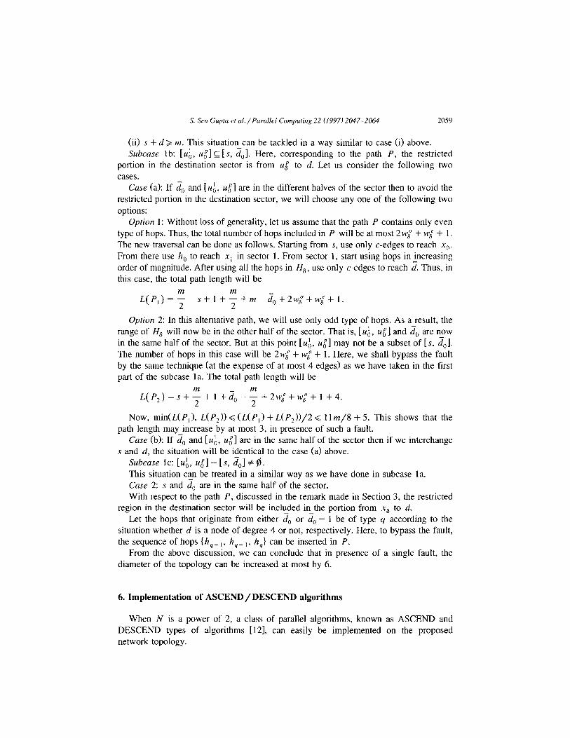
S. Sen Guptu et al./ Purallrl Computing 22 (1997) 2047-2064 2059
(ii) s + d > m. This situation can be tackled in a way similar to case (i) above. Subcuse lb: [z&, ~$1 L [s, &,I. Here, corresponding to the path P, the restricted
portion in the destination sector is from u [ to d. Let us consider the following two cases.
Case (a): If & and [ ZL~, ugl are in the different halves of the sector then to avoid the restricted portion in the destination sector, we will choose any one of the following two options:
Option 1: Without loss of generality, let us assume that the path P contains only even type of hops. Thus, the total number of hops included in P will be at most 2 wl + w: + 1. The new traversal can be done as follows. Starting from s, use only c-edges to reach x0. From there use h, to reach xl in sector 1. From sector 1, start using hops in increasing order of magnitude. After using all the hops in H,, use only c-edges to reach 2. Thus, in this case, the total path length will be
Option 2: In this alternative path, we will use only odd type of hops. As a result, the range of H, will now be in the other half of the sector. That is, [u;, uOp] and L?,, are now in the same half of the sector. But at this point [u:, ~$1 may not be a subset of [s, &I. The number of hops in this case will be 2 wi + wi + 1. Here, we shall bypass the fault by the same technique (at the expense of at most 4 edges) as we have taken in the first part of the subcase la. The total path length will be
L(P*)=s+;+* +&-;+2w;+w;+l+4.
Now, min(L(P,), L(P,)) < (L( P,> + L( P2))/2 < 11 m/8 + 5. This shows that the path length may increase by at most 3, in presence of such a fault.
Case (b): If & and [r& #I are in the same half of the sector then if we interchange s and d, the situation will be identical to the case (a> above.
Subcase lc: [u;, I*;] - [s, ;i,] # $. This situation can be treated in a similar way as we have done in subcase la. Case 2: s and 2, are in the same half of the sector. With respect to the path P, discussed in the remark made in Section 3, the restricted
region in the destination sector will be included in the portion from x8 to d. Let the hops that originate from either da or & - 1 be of type q according to the
situation whether d is a node of degree 4 or not, respectively. Here, to bypass the fault, the sequence of hops thy- ,, h,- ,, hq,) can be inserted in P.
From the above discussion, we can conclude that in presence of a single fault, the diameter of the topology can be increased at most by 6.
6. Implementation of ASCEND/DESCEND algorithms
When N is a power of 2, a class of parallel algorithms, known as ASCEND and DESCEND types of algorithms [12], can easily be implemented on the proposed network topology.

2060 S. Sen Gupta et al./ Pardel Computing 22 (1997) 2047-2064
Suppose, N = 2y and the input data a,, a,, . . . , uN-, are stored in the processors ml, Hll,..., P[ N - 11, respectively. An algorithm is in the ASCEND class if a sequence of operations is carried out between a pair of data that are successively 2O, 2’,. . . , 2q- ’ processor locations apart. In DESCEND class of algorithms, the operations are carried out just in reverse order. These classes of algorithms have applications in the problems like cyclic shift, bitonic merge, odd-even-merge, Fast Fourier Transform, sh@‘e, matrix transposition, bitonic sort, etc. Now, We shall discuss the implementation of such algorithms in our case. For brevity, we shall discuss here only the ASCEND type of algorithms. For the ease of discussion, let us first renumber the nodes of G(m, N).
Renumbering of nodes. L.et N = 2* and m = 2’. Therefore, q = 2’- ’ + r + 1. Since there are N/m = 2q-’ sectors, G(m, N) contains 2y- r cycles each of length m + 1, consists of m c-edges and a single hop h,. Let us number these cycles as 0, 1,. . . , 2y- ’ - 1, so that the cycles i and (i + 1) mod 2y-’ have one node in common. The node in cycle 0 from which the hop ho is originated, is now renumbered as 0. The remaining nodes are numbered from 1 to N - 1 along the largest cycle of length N, so that the cycle i now consists of the renumbered nodes {im, im + 1,. . . , (i + l>m}. We would also represent any such renumbered node by an ordered pair (I, p), 0 < I < 2y- r - 1, 0 < p < m - 1 = 2’ - 1, where 1 represents the cycle number which this node belongs to and p represents its distance from the node lm. Note that, since p < m, every node will have a unique representation by such an ordered pair. Thus, to address any of the N nodes, we require q bits in which the most significant q - r bits would represent the cycle number and the least significant r bits would represent the position of the node in the corresponding cycle. Also, if a node is renumbered as n, then, n = 1.2’ + p.
In our later discussions, we refer to a node by this renumbered value. Before going to discuss the implementation, we now describe an ASCEND type of
algorithm in the following two steps, where a basic operation between the two processors P[i] and P[r] has been indicated by OPER(i, j, P[ i], P[r]), when r = i + 2’. biti denotes the jth least significant bit of the binary representation of i.
Proc ASCEND
Step 1: / * Process data elements within each cycle of length m + 1. * / for each 1, 0 G 1 =z 2y- ’ - 1, do in parallel
for j=Oto r- 1 do for each p, 0 G p G 2’ - 1 do in parallel
if bitj( p) = 0 then OPER(p, j, PKl, ~11, P[(l + 2’, p)l
Step 2: / * Process data elements across the cycles. * / for j=r to q- 1 do for each i, 0 G i G N - 1 do in parallel
if bit, (i) = 0 then OPER(i, j, P[i], P[i + 2j])
S. Sen Guptu et d/Parallel Computing 22 (1997) 2047-2064 2061
0 1 2 3 4 5 6 7 8
/\ A A
+hz kthd &thz
Fig. 5. Hop distribution.
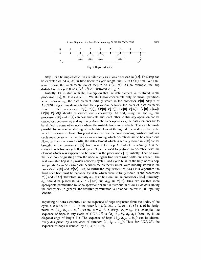
Step 1 can be implemented in a similar way as it was discussed in [12]. This step can be executed on G(m, N) in time linear in cycle length, that is, in O(m) time. We shall now discuss the implementation of step 2 on G(m, N). As an example, the hop distribution in cycle 0 of G(23, 2’) is illustrated in Fig. 5.
Initially, let us start with the assumption that the data element ai is stored in the processor P[ i], Vi, 0 < i < N - 1. We shall now concentrate only on those operations which involve aO, the data element initially stored in the processor P[O]. Step 2 of ASCEND algorithm demands that the operations between the pairs of data elements stored in the processors (P[Ol, P[81), (P[Ol, P[16]), (PLO], P[32]), (PLO], P[64]), (P[O], P[128]) should be carried out successively. At first, using the hop h,, the processor P[O] and P[8] can communicate with each other so that any operation can be carried out between a0 and us. To perform the later operations, the data elements are to be shifted to some other nodes where the suitable hops are available. This can be made possible by successive shifting of each data element through all the nodes in the cycle, which it belongs to. From this point it is clear that the corresponding positions within a cycle must be same for the data elements among which operations are to be carried out. Now, by three successive shifts, the data element which is actually stored in P[O] can be brought to the processor P[9] from where the hop h, (which is actually a direct connection between cycle 0 and cycle 2) can be used to perform an operation with the element which was supposed to be stored in the processor P[16] initially. Then to avail the next hop originating from the node 4, again two successive shifts are needed. The next available hop is h, which connects cycle 0 and cycle 8. With the help of this hop, an operation can be carried out between the elements which were initially stored in the processors P[O] and P[64]. But, to fulfill the requirement of ASCEND algorithm the third operation must be between the data which were initially stored in the processors P[O] and P[32]. Therefore, initially a32 must be stored in the processor P[64]. Similarly, ue4 should be placed initially in P[128] and a,28 in P[32]. Thus, we see that some appropriate permutation must be specified for initial distribution of data elements among the processors. In general, the required permutation is described below in the inputting scheme.
Inputting of data elements. Let the sequence of hops originated from the nodes of the cycle I, 0 < I< 2q-’ - 1, in the order (1, l), (1, 2),. . . ,(1, m - l), (I + 1, 0) be desig- nated as (hi,, hi,,. . . , hi=), where cy = 2’- ‘. Clearly, hia = h,. For example, the sequence of hops in any cycle of G(23, 28) is (h2, h,, h,, h,, h,) (here, h, is the diagonal edge of length 27). The sequence of hops (h,,, hi?,. . . , hi,) can be altema- tively designated by a sequence of numbers (i,, i,, . . . , i,). Thus, for G(23, 2’1, the sequence of hops is denoted by (2, 4, 3, 1,O).
2062 S. Sm Guptu et ul./ Parullel Computing 22 (1997) 2047-2064
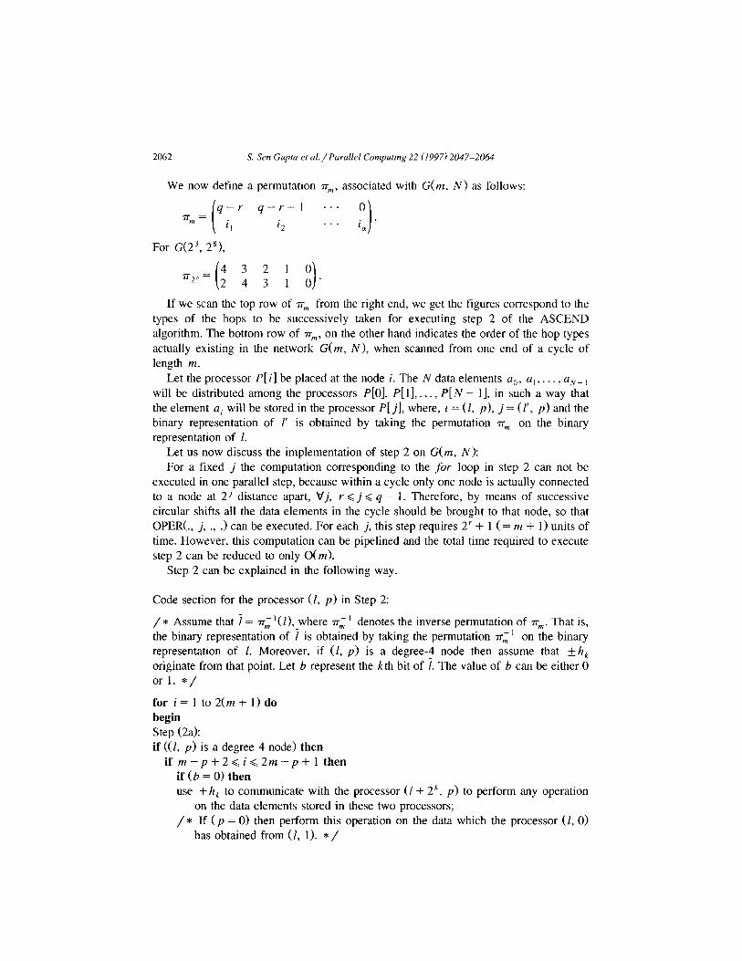
We now define a permutation TV, associated with G(m, N) as follows:
i
q-r q-r-l “. 0 “,= .
1’ 12 . . .
I i, ’
For G(23, 2’1,
r23 = ( 4 3 2 1 0 2 4 3 1 0 1 .
If we scan the top row of n-,,, from the right end, we get the figures correspond to the types of the hops to be successively taken for executing step 2 of the ASCEND algorithm. The bottom row of rr,,,, on the other hand indicates the order of the hop types actually existing in the network G(m, N), when scanned from one end of a cycle of length 172.
Let the processor P[ i] be placed at the node i. The N data elements aO, a,, . . . , a,+, will be distributed among the processors P[O], P[l], _ . . , P[N - 11, in such a way that the element a, will be stored in the processor P[ jl, where, i = (I, p>, j = (I’, p> and the binary representation of I’ is obtained by taking the permutation n-,,, on the binary representation of 1.
Let us now discuss the implementation of step 2 on G(m, N): For a fixed j the computation corresponding to the for loop in step 2 can not be
executed in one parallel step, because within a cycle only one node is actually connected to a node at 2 J distance apart, Vj, r < j < q - 1. Therefore, by means of successive circular shifts all the data elements in the cycle should be brought to that node, so that OPERA., j, ., .> can be executed. For each j, this step requires 2’ + 1 ( = m + 1) units of time. However, this computation can be pipelined and the total time required to execute step 2 can be reduced to only O(m).
Step 2 can be explained in the following way.
Code section for the processor (I, p) in Step 2:
/ * Assume that i = n-i ‘(I), where n-i ’ denotes the inverse permutation of n-,,,. That is, the binary representation of i is obtained by taking the permutation rr; ’ on the binary representation of 1. Moreover, if (I, p) is a degree-4 node then assume that k h, originate from that point. Let b represent the kth bit of 7. The value of b can be either 0 or 1. */
for i = 1 to 2(m + 1) do begin Step (2a): if ((1, p) is a degree 4 node) then
if m-p+2<i<2m-p+l then if(b=O)then use +h, to communicate with the processor (1+ 2k, p) to perform any operation
on the data elements stored in these two processors; / * If ( p = 0) then perform this operation on the data which the processor (I, 0)
has obtained from (1, 1). * /
S. Sen Guptu et al./ Parallrl Computing 22 (1997) 2047-2064 2063
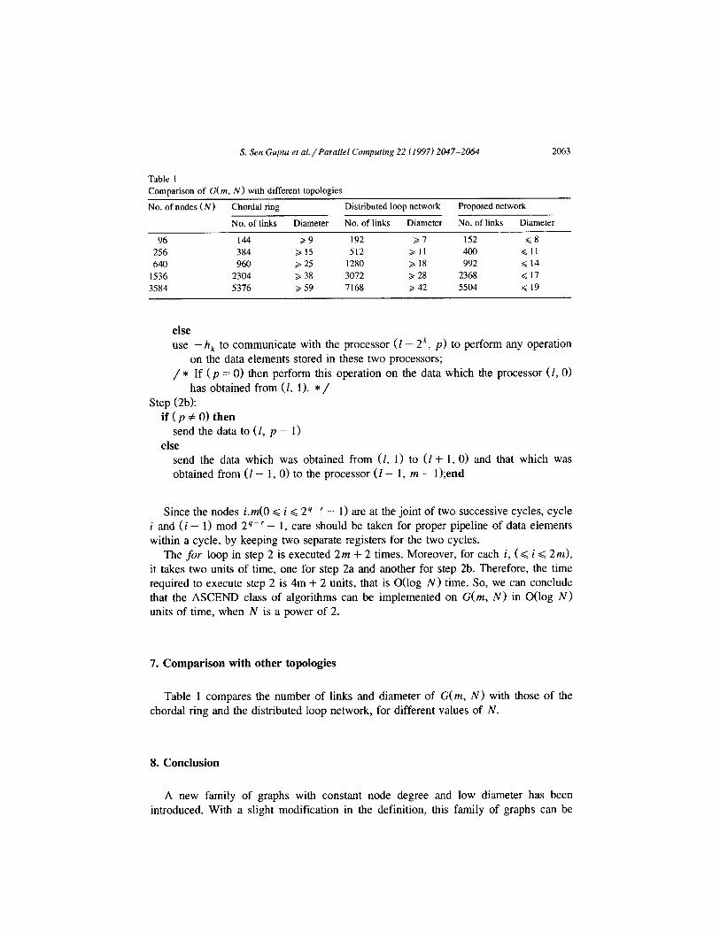
Table 1 Comparison of G(m, N) with different topologies
No. of nodes(N) Chordal ring Distributed loop network Proposed network
No. of links Diameter No. of links Diameter No. of links Diameter
96 144 >9 192 >7 1.52 5~8 256 384 > 15 512 > 11 400 d 11 640 960 > 25 1280 > 18 992 Q 14
1536 2304 > 38 3072 > 28 2368 Q 17 3584 5376 b 59 7168 > 42 5504 < 19
else use -h, to communicate with the processor (I - 2k, p) to perform any operation
on the data elements stored in these two processors; / * If ( p = 0) then perform this operation on the data which the processor (1,O)
has obtained from (I, 1). */ Step (2b):
if(p#O)then send the data to (1, p - 1)
else send the data which was obtained from (I, 1) to (I + 1, 0) and that which was obtained from (I - 1, 0) to the processor (I - 1, m - 1 );end
Since the nodes i.m(O < i < 2y-’ - 1) are at the joint of two successive cycles, cycle i and (i - 1) mod 2Y-’ - 1, care should be taken for proper pipeline of data elements within a cycle, by keeping two separate registers for the two cycles.
The fir loop in step 2 is executed 2m + 2 times. Moreover, for each i, (< i < 2m),
it takes two units of time, one for step 2a and another for step 2b. Therefore, the time required to execute step 2 is 4m + 2 units, that is O(log N) time. So, we can conclude that the ASCEND class of algorithms can be implemented on G(m, N) in O(log N) units of time, when N is a power of 2.
7. Comparison with other topologies
Table 1 compares the number of links and diameter of G(m, N) with those of the chordal ring and the distributed loop network, for different values of N.
8. Conclusion
A new family of graphs with constant node degree and low diameter has been introduced. With a slight modification in the definition, this family of graphs can be
2064 S. Sen Gupta et ul./Parallrl Computing 22 (1997) 2047-2064
constructed for all most all possible values of N. Given N, if N’ is the nearest number to N, N G N’, on which the graph is defined, then construct a graph with N’ nodes. Delete N’ - N number of degree 2 nodes, evenly from each sector. The diameter, D(N), would be upper bounded by D(N’) and the maximum node degree would remain same as in the original graph.
References
[I] S.G. AL], The Design uncl Analysis of Pnrullel Algorithms (Prentice-Hall, Englewood Cliffs, NJ, 1989). [2] S. Amo and F.S. Wheeler. Signed digit representation of minimal Hamming weight, lEEE Truns.
Comput. 42 (8) (1993) 1007-1010. [3] B.W. Arden and H. Lee, Analysis of chordal ring network, IEEE Truns. Comput. 4 (1981) 291-295.
[4] J.C. Bermond and D. Tzvieli, Minimal diameter double-loop networks: Dense optimal families, Nrhi’Orks
I(19911 I-10.
[5] F.T. Boesch and J.F. Wang, Circulants and their connectivities, J. Graph Theory 8 (1984) 487-499. [6] R.K. Das and B.P. Sinha, Optima1 communication algorithms in distributed loop networks, J. Pardel
Distributed Computing 30 (1995) 85-90.
[7] P.J. Davis, Circulant Matrices (John Wiley, New York, 1979). [8] N.G. de Bruijn, A combinatorial problem, Proc. Ken. Nederl. Acud. Wetensch. A 49 (1946) 758-764.
[9] F.T. Leighton, Introduction to Parallel A1gorithm.s and Architectures: Arruys. Trees, Hypercuhrs (Morgan Kaufmann, 1993).
[IO] W.E. Leland and M.H. Solomon, Dense trivalent graphs for processor interconnection, fEEE Trans.
Comput. 31 (1982) 219-222. [I I] J.H. Park and K.-Y. Chwa, Recursive circulant: A new topology for multicomputer networks, ISPAN
Proc. (1994) 73-80. [12] F.P. Preparata and J. Vuillemin, The cube-connected cycles: A versatile network for parallel computation,
Comm. ACM (May 1981) 300-309.
[13] G.W. Reitweisner, Binary arithmetic, Ad. in Comput. I (1960) 231-308. [14] S. Sen Gupta, R.K. Das, K. Mukhopadhyaya and B.P. Sinha, A multiple loop network with constant
degree and logarithmic diameter, Tech. Rept. No. P & E/E/003-96, Indian Statistical Institute, Calcutta.