A Distributed Address Configuration Scheme for a MANET
24
A Distributed Address Configuration Scheme for a MANET Xiaonan Wang • Huanyan Qian Received: 30 January 2012 / Revised: 6 December 2012 / Accepted: 5 February 2013 Ó Springer Science+Business Media New York 2013 Abstract This paper proposes a distributed address configuration scheme for a Mobile Ad hoc Network (MANET). The architecture for a MANET, the algorithm of constructing a MANET, and the algorithm for calculating a unique address space for the assignment are proposed. In the architecture, a common node has a unique address space for the assignment, and an isolated node can acquire a unique address from a neighboring common node without performing duplicate address detection. In this way, the address configuration task is distributed around common nodes. In this scheme, the control packets used for address configuration are exchanged within a one-hop scope, so the scalability is enhanced. This paper also presents an address recovery algorithm that can effectively retrieve the address resources released by failed nodes and the MANET merging/partitioning algorithm that can ensure a node’s address uniqueness. This paper compares the performance parameters of the proposed scheme and the existing schemes, including strong duplicate address detection and prime dynamic host configuration protocol, and the comparative results show that the address configuration cost of the proposed scheme is lower and the delay is shorter. Keywords Address tree Address recovery Network merging Network partitioning X. Wang (&) Changshu Institute of Technology, No. 99, Nansanhuan Street, Changshu City 215500, Jiangsu, China e-mail: [email protected] H. Qian Nanjing University of Science and Technology, No. 200, Xiaolingwei Street, Nanjing City 210094, Jiangsu, China e-mail: [email protected] 123 J Netw Syst Manage DOI 10.1007/s10922-013-9267-3
Transcript of A Distributed Address Configuration Scheme for a MANET

A Distributed Address Configuration Schemefor a MANET
Xiaonan Wang • Huanyan Qian
Received: 30 January 2012 / Revised: 6 December 2012 / Accepted: 5 February 2013
� Springer Science+Business Media New York 2013
Abstract This paper proposes a distributed address configuration scheme for a
Mobile Ad hoc Network (MANET). The architecture for a MANET, the algorithm
of constructing a MANET, and the algorithm for calculating a unique address space
for the assignment are proposed. In the architecture, a common node has a unique
address space for the assignment, and an isolated node can acquire a unique address
from a neighboring common node without performing duplicate address detection.
In this way, the address configuration task is distributed around common nodes. In
this scheme, the control packets used for address configuration are exchanged within
a one-hop scope, so the scalability is enhanced. This paper also presents an address
recovery algorithm that can effectively retrieve the address resources released by
failed nodes and the MANET merging/partitioning algorithm that can ensure a
node’s address uniqueness. This paper compares the performance parameters of the
proposed scheme and the existing schemes, including strong duplicate address
detection and prime dynamic host configuration protocol, and the comparative
results show that the address configuration cost of the proposed scheme is lower and
the delay is shorter.
Keywords Address tree � Address recovery � Network merging � Network
partitioning
X. Wang (&)
Changshu Institute of Technology, No. 99, Nansanhuan Street, Changshu City 215500,
Jiangsu, China
e-mail: [email protected]
H. Qian
Nanjing University of Science and Technology, No. 200, Xiaolingwei Street, Nanjing City 210094,
Jiangsu, China
e-mail: [email protected]
123
J Netw Syst Manage
DOI 10.1007/s10922-013-9267-3

1 Introduction
A MANET is a multi-hop wireless network without any infrastructures. In a
MANET, the wireless coverage area of a node is limited, so two nodes have to
depend on intermediate nodes to achieve communication. A node in a MANET
works as both a router and a host, so it needs to be configured with a unique address
to perform routing/forwarding functions.
In traditional networks, such as the Internet, the stateful address configuration
protocol [1] and the stateless address configuration protocol [2] based on DAD [3]
are employed to achieve address configuration, and the implementation of these
protocols is based on some infrastructures. Since a MANET has no such
infrastructures, these protocols are not suitable for a MANET.
An address configuration scheme for a MANET should have the following
characteristics:
1. Dynamic
In a MANET, some nodes may suddenly fail without an alert due to
unpredictable reasons. Also, new nodes may join a MANET at any time. Therefore,
an address configuration scheme for a MANET should be able to retrieve address
resources released by failed nodes and achieve address configuration for new nodes.
2. Uniqueness
If a node in a MANET wants to communicate with other nodes, then it has to be
configured with a unique address in order to ensure communication accuracy.
Therefore, an address configuration scheme must ensure the uniqueness of an
assigned address in a MANET.
3. Scalability
In general, address configuration cost increases exponentially with the total
number of nodes in a MANET. When a new node joins a MANET, it floods a packet
throughout a MANET and each node receiving the packet needs to return a response
packet to the new node [4]. Therefore, if the total number of nodes in a MANET is
n, then the address configuration cost tends to be O(n2) [5]. As a result, the
scalability is restricted. Therefore, an address configuration scheme should reduce
the cost in order to improve the scalability.
In this paper, we propose a distributed address configuration scheme for a
MANET, and it has the following contributions:
1. This paper proposes the architecture for a MANET, the algorithm of
constructing a MANET, and the algorithm for calculating a unique address
space for assignment. In the architecture, an isolated node can acquire a unique
address from a neighbor common node without performing DAD, and the
address resources released by failed nodes can be automatically recovered for
reuse. In this way, the dynamic address configuration is achieved.
2. Based on the proposed architecture, the distributed address configuration for a
MANET is achieved. In the architecture, each common node has a unique
J Netw Syst Manage
123

address space for assignment and can assign a unique address for isolated nodes
within a one-hop scope, so the address configuration task is distributed around
common nodes and the uniqueness of an assigned address is ensured.
3. The control packets used for the address configuration are exchanged within a
one-hop scope. Therefore, the address configuration cost is reduced and the
scalability is improved.
4. This paper proposes the MANET merging/partitioning algorithm, and the
algorithm effectively ensures the uniqueness of a node’s address in a MANET.
The remainder of this paper is organized as follows. In Sect. 2, we discuss the
related works on the address configuration schemes for a MANET. We discuss the
proposed address configuration scheme for a MANET in Sect. 3 and analyze
the performance of the proposed scheme in Sect. 4. We conclude the paper with a
summary in Sect. 5.
2 Related Works
Reference [6] describes some guides for IP(Internet Protocol) addressing in a
MANET and discusses the IP addressing modes for IPv4 (Internet Protocol version
4) and IPv6 (Internet Protocol version 6). In addition, reference [6] also points out
that the auto-configuration solutions for a MANET should not focus primarily on
configuring IP addresses that were IPv6 link-local.
At present, different address configuration schemes for a MANET have been
proposed. All these schemes can be classified into three categories [7]: neighbor-
based schemes, decentralized schemes, and centralized schemes.
In neighbor-based schemes, a new node is configured by one neighbor node, so
both network-wide flood and centralized control are avoided.
In scheme [4], a new node selected an initiator and then requested an address
from the initiator. The initiator assigned an address according to the address
configuration information in the local network. After the new node received the
assigned address, it broadcast the address across a MANET. If a node detected that
its address was equal to the received address, then it returned a Negative response.
Otherwise, it returned an Affirmative response. If no Negative responses were
returned, then the uniqueness of the assigned address was ensured. Since DAD was
performed in the entire network, the address configuration cost was relatively high.
In scheme [5], a new node broadcast a Discovery control packet to its
neighboring proxy nodes. A proxy node receiving the Discovery control packet
returned an Offer control packet to the new node. The new node selected the proxy
node with the minimum address as its father node, and then sent a Select control
packet to its father node. If the father node did not have the address resources, then
it requested the address resources from its ancestor nodes. Finally, the father node
returned an Ack packet whose payload was the assigned address to the new node. In
the situation where the father node had the address resources, the scheme effectively
reduced the address configuration cost. However, in the situation where the father
J Netw Syst Manage
123

node did not have the address resources, the address configuration cost was
increased and the delay was prolonged.
In scheme [8], a function f(n) generated a series of random numbers to achieve
the address configuration. The first node in a MANET generated a random number
and set its address to the number. The node used a random state value as a seed for
f(n). A new node acquired an address from the first node with a state value as the
seed for f(n). Whenever a node joined a MANET, the node performed the same
process to acquire an address. The main advantage of the scheme was that the
address configuration latency was short, and the cost was low. Its major drawback
was that even with a large address space the address conflict could still incur and it
was resolved by a passive DAD (PDAD) or a weak DAD.
Reference [9] defined a loose domain structure where a node in a domain could
roam to different domains after it acquired an address. This framework used PDAD
to solve the address conflict, so the network performance was potentially weakened.
Reference [10] proposed utilizing the Red, Green, Blue (RGB) coordinates to
achieve the address configuration. The address configuration cost was relatively low
but the scalability was limited. In addition, if the density of nodes increased, the
address configuration cost also grew substantially.
In scheme [11], the control packets were exchanged within a two-hop scope, so
the address configuration cost was reduced and the delay was shortened. If a proxy
node’s address space ran out, it broadcast an address recovery packet across the
whole network. After a proxy node received the address recovery packet, it also
broadcast an address recovery packet across the whole network. Therefore, during
one address recovery process, almost all proxy nodes in the network needed to
broadcast a packet, so a lot of network resources were consumed.
In dynamic address configuration protocol (DACP) [12], an elected address
authority (AA) maintained the address configuration information, and the unique-
ness of an allocated address was verified through DAD. In addition, a node
periodically sent a control packet to AA so that AA could update the node’s state
information in time. However, the control packets consumed a lot of network
resources.
In decentralized schemes, each node configures itself with an address, and then it
checks for duplicate addresses in the network. Usually these protocols suffer from
network-wide flooding.
Reference [13] proposed a stateless address configuration scheme based on DAD.
The scheme broadcast a DAD packet across the entire network, so DAD brought a
large number of control packets and consumed a lot of network resources.
Reference [14] proposed a DAD scheme based on the query mechanism, and the
scheme utilized the flooding mode to perform DAD. As a result, a lot of network
resources were consumed. References [15, 16] proposed an improved DAD scheme
based on the scheme [14]. The improved DAD cost was reduced, but the delay time
was prolonged and the reliability was weakened.
In scheme [17], each node maintained a set of unassigned addresses. If a node
moved out of the network, it returned its address to the corresponding set. Since the
sudden leave/failure of some nodes could cause the address resource loss, the
scheme employed the periodic-flooding query mechanism to reclaim the address
J Netw Syst Manage
123

resources released by failed nodes. However, the periodic-flooding query mecha-
nism consumed many network resources. In scheme [18], a node acquired its
location information by a global position system (GPS), and DAD was performed
by distributed DAD servers. However, it was hard for a mobile node to work as a
DAD server. In addition, it was unpractical to equip each node with a GPS.
Reference [19] proposed an IPv6 address configuration scheme for a wireless
sensor network (WSN) based on location information. The scheme reduced the
address configuration cost and shortened the delay substantially. The scheme [20]
presented the cluster-tree architecture, and created the layered IPv6 address format
for a cluster head and a cluster member, respectively. In the scheme, the DAD of an
address assigned for a cluster member was performed in a cluster, and the address
configuration for cluster members in different clusters was carried out at the same
time. However, the schemes [19, 20] did not discuss the network merging/
partitioning issues.
In scheme [21], a new node randomly selected an address, encapsulated the
address into an address request (AQ) packet, and broadcast the packet in the whole
network. If the address of a node receiving the packet was equal to the address in the
packet, then it returned an address reply (AQ) packet. If none of the nodes in
the network returned an AQ packet, then the address was considered to be unique in
the network. However, DAD consumed a lot of network resources.
In prime DHCP (PDHCP) [22], a node acquired a unique address without DAD.
In PDHCP, each node worked as a DHCP proxy, and used a prime numbering
address allocation (PNAA) algorithm to compute a unique address for new nodes.
However, PDHCP did not discuss the address recovery issue. If a DHCP proxy did
not have address resources, it asked its ancestor node to perform the address
configuration. In this situation, the address configuration cost was increased and the
delay was prolonged. In addition, if more than one new node joined a MANET at
the same time in the initial stage, the address conflict would incur.
In centralized schemes, a server in a network is responsible for assigning a
unique address for new nodes. The uniqueness of an assigned address is guaranteed,
but maintaining a server increases address configuration cost. In scheme [23], the
address allocation tables were used to achieve the address configuration. Since all
nodes in a MANET were mobile, maintaining the address allocation tables
consumed many network resources. In scheme [24], a sink node broadcast a control
packet to start the address allocation process. After a node received the control
packet broadcast by a sink node, it selected the sink node as its father node and then
requested an address. The father node extended its own address space by 1 bit and
assigned the extended address to the node. The scheme ensured address uniqueness
without DAD, but the address length increased the network resource consumption to
a certain extent.
Tree-based dynamic address auto-configuration protocol (T-DAAP) [25] divided
nodes into three categories: normal node, leader node, and root node. The normal
node only acted as a relay, and the leader node contained a disjoint free address pool
and was responsible for assigning an address for a new node. There was only one
root node in the network, and it stored information on all leaders in the network. The
root node was also responsible for address reclamation and network merging.
J Netw Syst Manage
123

Inevitably, the root node became the bottleneck and weakened the address
configuration performance.
The scheme [26] adopted the random ID and the time stamp to identify a new
node. Neighbor solicitation (NS) and neighbor advertisement (NA) were adopted to
perform the communication between a new node and a proxy node while REQ and
REP were used to achieve the communication between a proxy node and a gateway
node. Since a proxy node had to store the mapping between two kinds of packets,
the address configuration cost was increased and the delay was prolonged.
From the above discussion, it can be seen that the issue of how to achieve a low-
cost address configuration for a MANET needs future research.
3 Address Configuration Scheme
3.1 Architecture
The scheme includes two kinds of nodes:
1. Isolated node: A node that is not configured with an address.
2. Common node: A node that is configured with an address and has a unique
address space for assignment.
In our scheme, a MANET is uniquely identified by MANET ID that is j-bit long.
All nodes in a MANET form a tree topology that is called an address tree, and a
node in an address tree is uniquely identified by a node ID that is i-bit long. A
node’s address is made up of a MANET ID and a node ID, as shown in Table 1.
A MANET ID is generated through the random function when an address tree is
established, and a node ID is assigned when an address tree is initialized.
A common node in an address tree can have up to N child nodes, it divides
its address space into N equal parts, and each part is for one child node. For
example, the nth (0 B n B N - 1) child node of a root node has the address space
[L(n), U(n)] where L(n) and U(n) are shown in formulas (1) and (2).
LðnÞ ¼ 1 n ¼ 0n�2i
N 1� n�N
�ð1Þ
UðnÞ ¼ ðnþ 1Þ � 2i
N� 1 ð2Þ
In formulas (1) and (2), j, i and N are determined according to the size of a
MANET.
In our scheme, a node’s address is made up of two parts: a j-bit MANET ID and
an i-bit node ID, as shown in Table 1. The MANET ID corresponds to the subnet
prefix in IPv6/IPv4 while the node ID corresponds to the interface ID in IPv6/IPv4.
Table 1 Address structure
j bits i bits
MANET ID Node ID
J Netw Syst Manage
123

The values of i and j can be adjusted to satisfy the requirements of different Internet
protocols. For example, in IPv6, the sum of i and j is equal to 128 while in IPv4, the
sum is equal to 32. Therefore, the proposed scheme can work in both IPv6 and IPv4.
3.2 Data Structure
The scheme adopts the following packets to achieve the address configuration:
New_tree packet: A packet that is broadcast by an isolated node and whose
payload is the time stamp and a MANET ID.
Adv packet: A packet that is broadcast by a common node and whose payload is the
MANET ID and the total number of the child nodes whose states are Unassigned.
Req packet: A packet that is sent by an isolated node to its father node to request
an address.
Res packet: A packet that is a response packet to a Req packet, and whose
payload is the child value and both the upper limit and lower limit of the
corresponding address space.
Update packet: A packet that is sent by a child node to its father node to show its
normal working state.
Update_res packet: A packet that is a response packet to an Update packet, and
that is sent by a father node to its child node to show its normal working state.
Detection_merge packet: A packet that is sent to a root node to launch the
MANET merging operation.
Merge packet: A packet that is sent by a root node to another root node to
perform the MANET merging operation.
Merge_res packet: A packet that is a response packet to a Merge packet to show
that the MANET merging operation is being performed.
Addr_change packet: A packet that is sent by a father node to its child nodes to
update the parameters.
3.3 Election of a Root Node and Establishment of an Address Tree
In our scheme, a common node periodically broadcasts an Adv packet within a one-
hop scope.
If an isolated node X does not receive any Adv packets within the specified time,
then it launches a root node’s election process and begins to establish an address tree
according to the following steps:
1. An isolated node X broadcasts a New_tree packet within a one-hop scope, and
the payload of the packet is the time stamp and the MANET ID generated
through the random function.
2. After a neighbor node receives the New_tree packet, it compares the priority of
the received New_tree packet with the one of its New_tree packet. If the
priority of the received New_tree packet is higher, then the neighbor node
broadcasts the received New_tree packet; otherwise, it abandons the packet.
The above process is repeated until all nodes in a MANET receive the
New_Tree packet with the highest priority.
J Netw Syst Manage
123

3. If the New_tree packet sent by X has the highest priority in the specified time,
then X marks itself as a root node; otherwise, X marks the node Y as its father
node that forwards the New_tree packet with the highest priority.
4. In this way, a root node is elected and an address tree is established.
Through the above process, it can be seen that the isolated node with the highest
priority in a MANET is elected as a root node and all nodes in a MANET form an
address tree, as shown in Fig. 1.
At the time T1, an isolated node X launches a root node’s election process and
begins to establish an address tree, as shown in Fig. 1a. At the time T2, the isolated
node Y with the highest priority is elected as a root node and all nodes form an
address tree where the node X marks the node Y as its father node that forwards the
New_tree packet with the highest priority, as shown in Fig. 1b.
The priority algorithm of a New_Tree packet is similar to the one in Reference
[25], and is described as follows:
• If the time stamp in a New_tree packet T is earlier than the one in another
New_tree packet T0, then the priority of T is higher than the one of T0;• If the time stamp in T is equal to the one in T0 and the MANET ID in T is less
than the one in T0, then the priority of T is higher than the one of T0.
Reference [25] has proven that the priorities of any two packets are different.
3.4 Address Configuration
3.4.1 Initialization of an Address Tree
In our scheme, a node in an address tree stores a child table where each entry
corresponds to one child node. One entry contains the following fields: the child
value k (0 B k B N - 1), the child node state (Unassigned or Assigned), and the
upper limit and lower limit of the address space. For example, if a node ID is i-bit
(a)
(b)
Fig. 1 Process of establishingan address tree
J Netw Syst Manage
123
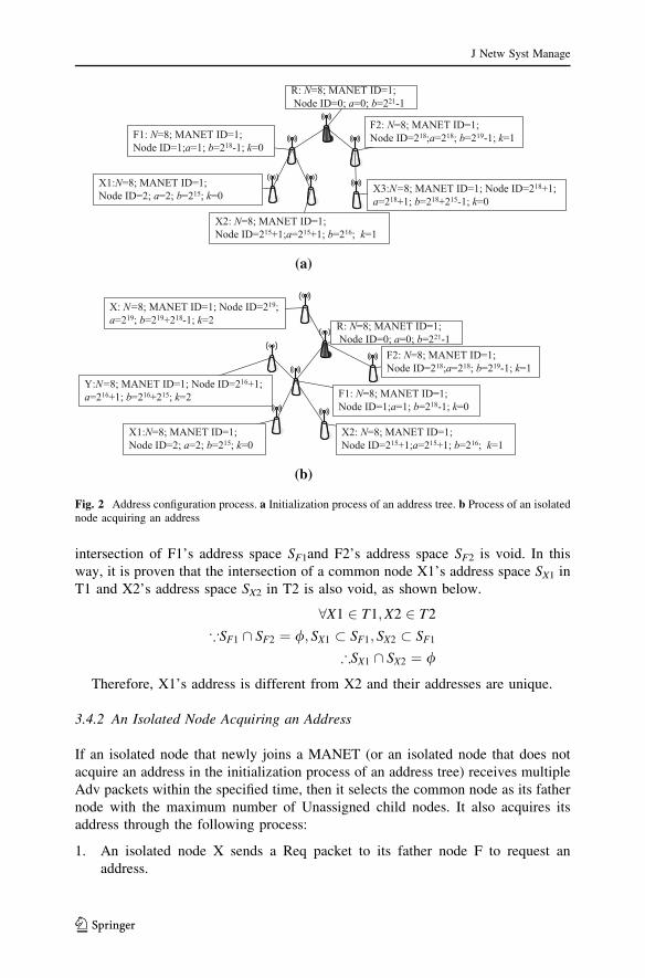
long, then the address space of a root node is [0, 2i - 1]. The root node sets its node
ID to 0, marks itself as a common node, and combines its node ID with the MANET
ID to form its address. Then the root node divides the address space [1, 2i - 1] into
N equal parts and each part is for one child node. The address space of the nth
(0 B n B N - 1) child node is [L(n), U(n)], the nth child node sets its node ID to
L(n), divides the address space [L(n) ? 1, U(n)] into N equal parts again and each
part is for one child node, and so forth.
After a root node acquires its address, it broadcasts an Adv packet within a one-
hop scope. After an isolated node receives an Adv packet broadcast by its father
node, it checks if the total number of the unassigned child nodes is equal to 0. If it is,
then the isolated node selects a new father node to acquire a node ID. Otherwise, the
isolated node acquires an address through the following process:
1. An isolated node X sends a Req packet to its father node F to request an
address.
2. After F receives the Req packet, it selects an entry with the Unassigned state
from its child node table, and then returns a Res packet whose payload includes
the child value k of the selected entry and the upper limit b and lower limit a of
the address space of the selected entry. At the same time, F sets the child node
state in the selected entry to Assigned.
3. After X receives the Res packet, it sets its node ID to a, combines its node ID
with the MANET ID to form its address, and then establishes a child table that
includes N entries. X divides the address space [a ? 1, b] into N equal parts,
and each part is for one child node that corresponds to one entry. For example,
for the entry whose child value is k (0 B k B N - 1), the address space is
aþ 1þ kðb�aÞN
j k; aþ ðkþ1Þðb�aÞ
N
j kh i. If the upper limit of the address space
is less than the lower limit, then the child node state in the corresponding entry
is set to Assigned. Otherwise, it is set to Unassigned. Finally, X marks itself as a
common node and broadcasts an Adv packet.
4. The above process is repeated recursively until all the nodes in the address tree
acquire an address.
5. The initialization process of an address tree ends, as shown in Fig. 2a.
In Fig. 2a, after the root node R acquires an address, its child nodes F1 and F2 obtain
a unique address from R. In this way, the nodes X1 and X2 acquire an address from its
father node F1, and the node X3 obtains an address from its father node F2.
In the initialization process of an address tree, after a node in an address tree
acquires an address and changes into a common node, it begins to perform the
address configuration for its child nodes. Therefore, the address configuration task is
distributed around all common nodes in an address tree and multiple common nodes
in an address tree can perform the address configuration for their child nodes at the
same time. In this way, the distributed address configuration is achieved.
In our scheme, each common node’s address space is unique, so its address is
also unique. It is assumed that the common nodes F1 and F2 are the common node
R’s child nodes, the sub-tree whose root node is F1 is called T1 and the sub-tree
whose root node is F2 is called T2. Then, according to the above algorithm, the
J Netw Syst Manage
123
intersection of F1’s address space SF1and F2’s address space SF2 is void. In this
way, it is proven that the intersection of a common node X1’s address space SX1 in
T1 and X2’s address space SX2 in T2 is also void, as shown below.
8X1 2 T1;X2 2 T2
*SF1 \ SF2 ¼ /; SX1 � SF1; SX2 � SF1
)SX1 \ SX2 ¼ /
Therefore, X1’s address is different from X2 and their addresses are unique.
3.4.2 An Isolated Node Acquiring an Address
If an isolated node that newly joins a MANET (or an isolated node that does not
acquire an address in the initialization process of an address tree) receives multiple
Adv packets within the specified time, then it selects the common node as its father
node with the maximum number of Unassigned child nodes. It also acquires its
address through the following process:
1. An isolated node X sends a Req packet to its father node F to request an
address.
(a)
(b)
Fig. 2 Address configuration process. a Initialization process of an address tree. b Process of an isolatednode acquiring an address
J Netw Syst Manage
123
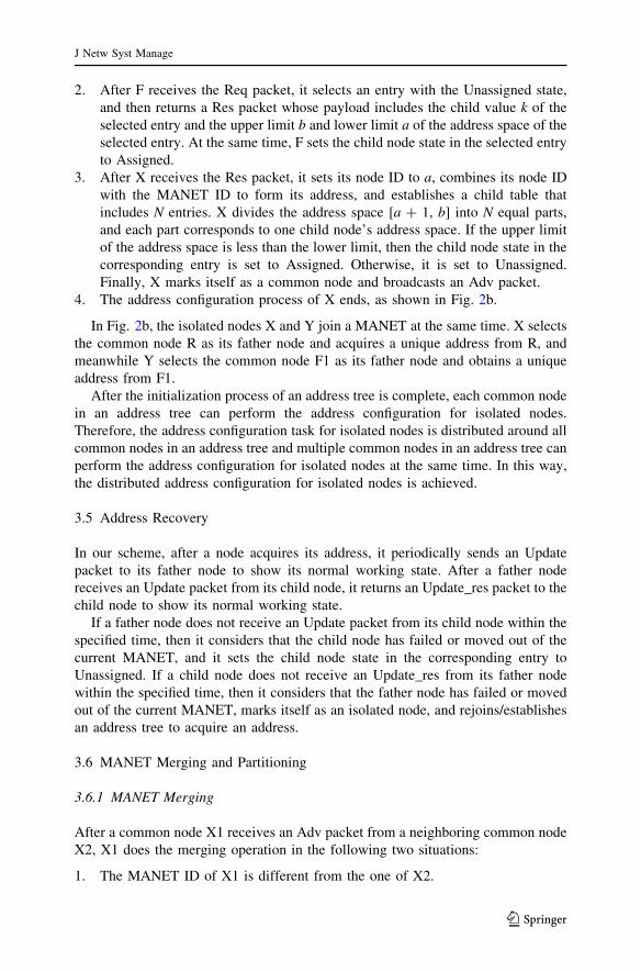
2. After F receives the Req packet, it selects an entry with the Unassigned state,
and then returns a Res packet whose payload includes the child value k of the
selected entry and the upper limit b and lower limit a of the address space of the
selected entry. At the same time, F sets the child node state in the selected entry
to Assigned.
3. After X receives the Res packet, it sets its node ID to a, combines its node ID
with the MANET ID to form its address, and establishes a child table that
includes N entries. X divides the address space [a ? 1, b] into N equal parts,
and each part corresponds to one child node’s address space. If the upper limit
of the address space is less than the lower limit, then the child node state in the
corresponding entry is set to Assigned. Otherwise, it is set to Unassigned.
Finally, X marks itself as a common node and broadcasts an Adv packet.
4. The address configuration process of X ends, as shown in Fig. 2b.
In Fig. 2b, the isolated nodes X and Y join a MANET at the same time. X selects
the common node R as its father node and acquires a unique address from R, and
meanwhile Y selects the common node F1 as its father node and obtains a unique
address from F1.
After the initialization process of an address tree is complete, each common node
in an address tree can perform the address configuration for isolated nodes.
Therefore, the address configuration task for isolated nodes is distributed around all
common nodes in an address tree and multiple common nodes in an address tree can
perform the address configuration for isolated nodes at the same time. In this way,
the distributed address configuration for isolated nodes is achieved.
3.5 Address Recovery
In our scheme, after a node acquires its address, it periodically sends an Update
packet to its father node to show its normal working state. After a father node
receives an Update packet from its child node, it returns an Update_res packet to the
child node to show its normal working state.
If a father node does not receive an Update packet from its child node within the
specified time, then it considers that the child node has failed or moved out of the
current MANET, and it sets the child node state in the corresponding entry to
Unassigned. If a child node does not receive an Update_res from its father node
within the specified time, then it considers that the father node has failed or moved
out of the current MANET, marks itself as an isolated node, and rejoins/establishes
an address tree to acquire an address.
3.6 MANET Merging and Partitioning
3.6.1 MANET Merging
After a common node X1 receives an Adv packet from a neighboring common node
X2, X1 does the merging operation in the following two situations:
1. The MANET ID of X1 is different from the one of X2.
J Netw Syst Manage
123

2. The address of X1 is equal to the one of X2.
It is assumed that X1 is located in MANET1 that corresponds to the address tree T1,
and X2 is located in MANET2 that corresponds to the address tree T2. X1 performs the
merging operation of MANET1 and MANET2 through the following process:
1. X1 sends a Detection_merge packet to the root node R1 of T1, and the payload
of the Detection_merge packet is the MANET ID of MANET2.
2. After R1 receives the Detection_merge packet, it selects an entry with the
Unassigned state and sends a Merge packet to the root node R2 of T2. The
payload of the Merge packet includes the MANET ID of MANET1, the child
value k of the selected entry, and the upper limit b as well as lower limit a of the
address space in the selected entry.
3. After R2 receives the Merge packet, it marks R1 as its father node and returns a
Merge_res packet to R1. Then R2 sets its node ID to a and combines the
MANET ID of MANET1 with the node ID to form its address. Finally, R2
divides its new address space [a ? 1, b] into N equal parts, and each part is
used to update the upper limit and lower limit of the address space in the
corresponding entry of the child node table. If the child node state in one entry
is Assigned, then R2 sends an Addr_change packet to the corresponding child
node, and the payload of the Addr_change packet is the MANET ID of
MANET1 as well as the upper limit and lower limit of the address space in the
corresponding entry.
4. After the child node receives the Addr_change packet, it sets its node ID to the
lower limit of the address space in the Addr_change packet, combines
the MANET ID of MANET1 with the node ID to form its address, and updates
the upper limit and lower limit of the address space with the new ones in the
Addr_change packet. Then the child node divides the new address space into
N equal parts, and each part is used to update the upper limit and lower limit of
the address space in the corresponding entry. If the child node state in one entry
is Assigned, then the child node sends an Addr_change packet to its
corresponding child node and the payload of the Addr_change is the MANET
ID of MANET1 as well as the upper limit and lower limit of the address space
in the corresponding entry. The above process is repeated recursively until all
the nodes in MANET2 update the addresses as well as the upper limits and
lower limits of the address spaces.
5. After R1 receives the Merge_res packet, it sets to Assigned the child node state
in the entry with the child value k.
6. The merging process of MANET1 and MANET2 ends, and the MANET ID of
the merged MANET is the MANET ID of MANET1, as shown in Fig. 3a–c.
Figure 3a shows that there are two MANETs, MANET1 and MANET2 before
the merging operation is performed. In Fig. 3b, the common node X1 detects that its
MANET ID is different from the one of its neighbor node X2, so it launches the
MANET merging operation. After the merging operation is performed, MANET1
and MANET2 are merged into MANET3. Figure 3c shows the control flow of the
MANET merging operation.
J Netw Syst Manage
123

In the above process, if R2 receives more than one Merge packet, then it only
responds to the first Merge packet.
3.6.2 MANET Partitioning
If a common node X does not receive any Adv packets from its neighbor nodes in
the current MANET within the specified time, or the MANET IDs of the received
Adv packets all belong to another MANET, then it marks itself as an isolated node.
In the former situation, X begins to establish an address tree to acquire an address.
In the latter situation, X joins another MANET to acquire an address.
R2: N=8; MANET ID=1; Node ID=218;a=218;b=219-1; k=1
X2: N=8; MANET ID=1; Node ID=218+1;a=218+1;b=218+215-1;k=0
C: N=8; MANET ID=1; Node ID=218+215;a=218+215;b=218+216-1;k=1R1: N=8; MANET ID=1; Node ID=0;
a=0;b=221-1
N=8; MANET ID=1; Node ID=1;a=1; b=218-1; k=0
N=8; MANET ID=1; Node ID=2;a=2; b=215;k=0
X1: N=8; MANET ID=1; Node ID=215+1;a=215+1; b=216; k=1
MANET3
(a)
(b)
(c)
Fig. 3 MANET merging process. a Before merging. b After merging. c Merging control flow
J Netw Syst Manage
123

Figure 4a–c show the MANET partitioning process in the former situation.
Figure 4a shows that the common node X is located in MANET1 before the
partitioning operation is performed. X has a father node R and two child nodes, C1 and
C2. In Fig. 4b, X, C1, and C2 move out of MANET1. Since X cannot receive a
Res_update packet from R, it marks itself as an isolated node. Similarly, C1 and C2
cannot receive a Res_update packet from X, so they also mark themselves as an
(a)
(b)
(c)
Fig. 4 MANET partitioning process. a Before partitioning. b X, C1 and C2 moving out of MANET1.c After partitioning
J Netw Syst Manage
123

isolated node. Since X, C1, and C2 cannot receive any Adv packet from its neighbor
nodes in MANET1, they begin to establish an address tree. Finally, an address tree
whose root node is X is successfully established and it corresponds to MANET2. In
this way, the original MANET1 is partitioned into two MANETs, as shown in Fig. 4c.
4 Performance Evaluation
4.1 Theoretical Evaluation
PDCHP [22] and Strong DAD [21] are selected to compare with the proposed
scheme due to the following reasons:
1. Compared with the existing address configuration schemes, the address
configuration cost of PDCHP is lower and the delay is shorter [5].
2. Strong DAD is a typical address configuration scheme for a MANET [27].
When an isolated node requests to acquire an address, the address configuration cost
and delay are analyzed and proved by using the proof methods in Reference [28].
In Strong DAD, an isolated node randomly selects an address, encapsulates the
address into an AQ packet and broadcasts the packet across the whole network. If a
node receiving the packet detects that its address is equivalent to the address in the
packet, then it returns an AP packet. If the new node does not receive an AP packet
within the time specified by the timer, then it repeats broadcasting an AQ packet. If
the new node does not receive an AP packet after broadcasting an AQ packet
m times, then the selected address is considered to be unique. Therefore, the upper
bounds of the cost and delay for a node acquiring an address are mO(N - 1) and
2mO(d), respectively, where N is the total number of nodes in the network and d is
the maximum length of the unicast routing path through which an AP packet is
returned to the isolated node.
Proof. The upper bound of the cost of broadcasting an AP packet in the whole
network is O(N - 1), so the one of broadcasting an AP packet m times is mO(N - 1).
The upper bound of the delay of broadcasting an AP/AQ packet is O(d), so the upper bound
of the delay of both broadcasting an AP packet and waiting for an AQ packet m times is
2mO(d). In this way, the upper bounds of the cost and delay for the m number of success
trials are mO(N - 1) and 2mO(d) respectively.
In PDHCP, an isolated node first broadcasts a DHCP_Discover packet within a
one-hop scope. After a neighbor DHCP Proxy node receives the packet, it checks if
it has the address space for assignment. If the DHCP proxy node has, then it returns
a DHCP_Offer packet to the isolated node. Otherwise, the proxy node forwards the
received DHCP_Discover packet to its father node. The former situation is called
PDHCP-1 and the latter situation is called PDHCP-2. In PDHCP-2, if the father
node does not have the address space for assignment, then it continues to forward
the DHCP_Discovery packet to its father node. The above process is repeated until
the packet arrives at an ancestor node that has the address space for assignment.
Then the ancestor node returns a DHCP_Offer packet to the isolated node. If the
isolated node receives more than one DHCP_Offer packet, then it selects the DHCP
J Netw Syst Manage
123

proxy node with the smallest address as its father node and sends a DHCP_Request
packet to its father node. After the father node receives the DHCP_Request packet,
it returns a DHCP_Ack packet whose payload is an assigned address to the isolated
node. In PDHCP-1, the packets exchanged between an isolated node and a DHCP
Proxy node are transmitted within a one-hop scope. In PDHCP-2, the packets are
exchanged between an isolated node and an ancestor node. Therefore, in PDHCP-1
the upper bounds of the cost and delay for a node acquiring an address are
2O(N1) ? 2O(1) and 4O(1), respectively, and in PDHCP-2 the ones for a node
acquiring an address are 2O(N1�d) ? 2O(d) and 4O(d), respectively. N1 is the
number of neighbor DHCP proxy nodes of an isolated node and d is the maximum
length of the unicast routing path from the isolated node to its remote father node.
Proof. In PDHCP-1, the upper bounds of the cost and delay of broadcasting a
DHCP_Discover packet between an isolated node and a neighbor DHCP proxy node
are O(N1) and O(1), respectively. The ones of the neighbor DHCP proxy nodes
returning a DHCP_Offer packet are also O(N1) and O(1), respectively. In addition,
the ones of unicasting a DHCP_Request/DHCP_Ack are O(1) and O(1), respec-
tively. Therefore, the upper bounds of the cost and delay for a node acquiring an
address are 2O(N1) ? 2O(1) and 4O(1), respectively. In PDHCP-2, the upper
bounds of the cost and delay of broadcasting a DHCP_Discover packet between an
isolated node and a remote ancestor node are O(N1�d) and O(d), respectively. The
ones of the remote ancestor nodes returning a DHCP_Offer packet are also
O(N1�d) and O(d), respectively, while the ones of unicasting a DHCP_Request/
DHCP_Ack between an isolated node and a remote father node are O(d) and
O(d) respectively. Therefore, the upper bounds of the cost and delay for a node
acquiring an address are 2O(N1�d) ? 2O(d) and 4O(d), respectively.
In the proposed scheme, after an isolated node receives the Adv packets
broadcast by neighbor common nodes, it sends a Req packet to the common node
with the maximum number of the unassigned child nodes in the Unicast way. After
the common node receives the Req packet, it returns to the isolated node a Res
packet whose payload is the unique address assigned for the isolated node.
Therefore, the upper bounds of the cost and delay for a node acquiring an address
are O(N1) ? 2O(1) and 3O(1), respectively.
Proof. In the proposed scheme, the upper bounds of the cost and delay of an
isolated node’s neighboring common nodes broadcasting an Adv packet are O(N1)
and O(1), respectively. The ones of unicasting a Req/Res packet are O(1) and O(1),
respectively. Therefore, the upper bounds of the cost and delay for a node acquiring
an address are O(N1) ? 2O(1) and 3O(1), respectively.
In order to minimize the address configuration cost and delay for Strong DAD,
m is set to 1. In this way, the comparison results of the address configuration cost
and delay for an isolated node acquiring a unique address are shown in Tables 2 and
3, respectively.
4.2 Simulation Evaluation
We compare the performance parameters of Strong DAD, PDHCP, and the
proposed scheme. The performance parameters include the cost and delay for an
J Netw Syst Manage
123

isolated node acquiring an address and the cost and delay for all nodes in a MANET
acquiring an address. The cost for an isolated node acquiring an address is measured
by the number of packets used by the isolated node to acquire an address, and the
delay for an isolated node acquiring an address is measured by the time taken by an
isolated node acquiring an address. The cost for all nodes in a MANET acquiring an
address is measured by the number of packets used to assign an address for all nodes
in a MANET, and the delay for all nodes in a MANET acquiring an address is
measured by the time taken by assigning an address for all nodes in a MANET.
4.2.1 Simulation Environment
NS-2 [28] is used to simulate Strong DAD, PDHCP and the proposed scheme. The
NS-2 simulation parameters are shown in Table 4. In Table 4, the common
parameters for a MANET are used to evaluate the performance of the proposed
scheme. Among them, the number of nodes ranges from 10 to 50 so that the effect
of node population on the address configuration performance can be evaluated. The
Table 2 Address configuration cost comparison table
Scheme name Broadcasting packet cost Unicast packet cost Total cost
Strong DAD O(N - 1) 0 O(N - 1)
PDHCP-1 2O(N1) 2O(1) 2O(N1) ? 2O(1)
PDHCP-2 2O(N1�d) 2O(d) 2O(N1�d) ? 2O(d)
Proposed scheme O(N1) 2O(1) O(N1) ? 2O(1)
Table 3 Address configuration
delay comparison tableScheme name Broadcasting
packet delay
Unicast
packet delay
Total
delay
Strong DAD 2O(d) 0 2O(d)
PDHCP-1 2O(1) 2O(1) 4O(1)
PDHCP-2 2O(d) 2O(d) 4O(d)
Proposed scheme O(1) 2O(1) 3O(1)
Table 4 ParametersParameter description Parameter value
Mobility model Random waypoint
mobility model
Pause time 5 s
Maximum speed 20 m/s
Communication range of a node 250 m
MAC protocol IEEE 802.11
Simulation area 750 m 9 750 m
Number of nodes 10–50
J Netw Syst Manage
123

speed ranges from 0 to 20 m/s so that the effect of speed on the address
configuration performance can be assessed.
When the cost and delay for an isolated node acquiring an address are evaluated,
the isolated nodes join a MANET one by one at the random interval to obtain the
average simulation data. In this way, the cost and delay for an isolated node
acquiring an address can be obtained. When the cost and delay for all nodes in a
MANET acquiring an address are assessed, the isolated nodes join a MANET at the
same time to obtain the corresponding simulation data. In this way, the cost and
delay for all nodes in a MANET acquiring an address can be obtained.
4.2.2 Effect of Node Population
When the maximum speed is 10 m/s, the address configuration cost and delay are
shown in Figs. 5, 6, 7, and 8.
In Strong DAD, an isolated node broadcasts an AQ packet in the whole network,
so the cost CStrong for a node acquiring an address increases proportionally with the
total number n of nodes in the network and the cost C0Strong for all nodes acquiring an
address tends to increase proportionally with n�n, as shown in formulas (3) and (4).
Since the maximum length d of the routing path in the network tends to increase
proportionally with n, the delay TStrong for a node acquiring an address tends to
increase proportionally with n, as shown in formula (5) where T1 is a one-hop
transmission delay and is a constant. When all isolated nodes in the network
perform the address configuration at the same time, the maximum delay t0 of an AQ
packet queuing in an intermediate node tends to grow proportionally with n.
Therefore, the delay T 0Strong for all nodes acquiring an address tends to increase
proportionally with t0 � d þ T1 � d, as shown in formula (6), where T4 is the delay of
an intermediate node routing/forwarding an AQ packet.
CStrong / n ð3Þ
C0Strong / n2 ð4Þ
TStrong / d � T1 / n � T1 ð5Þ
T 0Strong / ðt0 � d þ T1 � dÞ / ðn2 � T4þ n � T1Þ ð6Þ
In PDHCP-1, when the simulation area is unchanged, the node density tends to
increase proportionally with n. As a result, the number n1 of neighbor proxy nodes
Fig. 5 Cost for a nodeacquiring an address based onpopulation
J Netw Syst Manage
123

of an isolated node also tends to grow proportionally with n. Therefore, the cost
CPDHCP-1 for a node acquiring an address tends to increase proportionally with n and
the cost C0PDHCP�1 for all nodes acquiring an address tends to increase proportionally
with n � n, as shown in formulas (7) and (8). Since the control packets are
exchanged within a one-hop scope, the delay TPDHCP-1 for a node acquiring an
address tends to be constant. In the early stage, the address configuration for nodes
tends to be performed in serial, so the delay T 0PDHCP�1 for all nodes acquiring an
address tends to increase proportionally with n�TPDHCP-1, as shown in formula (9).
In the late stage, the address configuration for multiple nodes can be performed in
parallel and the number n’ of the nodes performing the address configuration in
parallel tends to increase proportionally with n, so the delay T 0PDHCP�1 for all nodes
acquiring an address tends to be constant.
CPDHCP�1 / n1 / n ð7Þ
Fig. 6 Delay for a nodeacquiring an address based onpopulation
Fig. 7 Cost for all nodesacquiring an address based onpopulation
Fig. 8 Delay for all nodesacquiring an address based onpopulation
J Netw Syst Manage
123

C0PDHCP�1 / n1 � n / n2 ð8Þ
T 0PDHCP�1 / n � TPDHCP�1 ð9ÞIn PDHCP-2, the control packets are exchanged between an isolated node and
remote ancestor nodes. The number n1 of neighboring proxy nodes of an isolated
node tends to grow proportionally with n and the maximum length d of the unicast
routing path from an isolated node to its remote father node also tends to grow
proportionally with n. Therefore, the cost CPDHCP-2 for a node acquiring an address
tends to increase proportionally with n�d ? d, and the cost C0PDHCP�2 for all nodes
acquiring an address tends to increase proportionally with n � ðn � d þ dÞ, as shown
in formulas (10) and (11). Since the control packets are exchanged between an
isolated node and remote ancestor nodes, the delay TPDHCP-2 tends to increase
proportionally with d, as shown in formula (12). In general, PDHCP-2 is only
performed in the late stage where a neighboring proxy node lacks the address space
for assignment. In the late stage, the address configuration for multiple nodes can be
performed in parallel and the number n0 of the nodes performing the address
configuration in parallel tends to increase proportionally with n. Since the maximum
delay t00 of a control packet queuing in an intermediate node tends to grow
proportionally with n, the delay T 0PDHCP�2 for all nodes acquiring an address tends to
increase proportionally with nn0 � ðt00 þ T1Þ � d, as shown in formula (13).
CPDHCP�2 / ðn1 � d þ dÞ / ðn2 þ nÞ ð10Þ
C0PDHCP�2 / n � ðn1 � d þ dÞ / n � ðn2 þ nÞ ð11ÞTPDHCP�2 / d � T1 / n � T1 ð12Þ
T 0PDHCP�2 /n
n0� ðt00 þ T1Þ � d / n � ðn � T4þ T1Þ ð13Þ
In PDHCP, in the early stage, since a proxy node has enough address space for
assignment, PDHCP-1 is performed to achieve the address configuration. In the late
stage, when a proxy node lacks the address space for assignment, PDHCP-2 is
fulfilled to accomplish the address configuration. Therefore, in the early stage of the
address configuration, the simulation data show the characteristics of PDHCP-1
while in the late stage the simulation data show the mixed characteristics of
PDHCP-1 and PDHCP-2.
In the proposed scheme, when the simulation area is unchanged, the node density
tends to increase proportionally with n. As a result, the number n1 of neighboring
common nodes of an isolated node also tends to grow proportionally with n, so the
cost C for a node acquiring an address tends to increase proportionally with n and
the cost C0 for all nodes acquiring an address tends to increase proportionally with
n�n, as shown in formulas (14) and (15). Since the control packets are exchanged
within a one-hop scope, the delay T for a node acquiring an address tends to be
constant. In the early stage, the address configuration for nodes tends to be
performed in serial, so the delay T0 for all nodes acquiring an address tends to
increase proportionally with n�T, as shown in formula (16). In the late stage, the
address configuration for multiple nodes can be performed in parallel and the
J Netw Syst Manage
123

number n0 of the nodes performing the address configuration in parallel tends to
increase proportionally with n, so the delay T0 for all nodes acquiring an address
tends to be constant.
C / n1 / n ð14Þ
C0 / n1 � n / n2 ð15ÞT 0 / n � T ð16Þ
In PDHCP, a DHCP proxy node cannot retrieve the address resources released by
nodes that fail/move out of a MANET, so its address space for assignment is limited
significantly. In the proposed scheme, a common node can effectively recycle the
address resources released by nodes that fail/move out of a MANET, so its address
space tends to be a constant when the number of isolated nodes is balanced with one
of the nodes that fail/move out of a MANET. Therefore, a common node always has
the sufficient address space for assignment. As a result, the proposed scheme has a
better performance than PDHCP.
4.2.3 Effect of Speed
When the number of nodes is 50, the address configuration cost and delay are shown
in Figs. 9, 10, 11 and 12.
It is assumed that the communication range R and the mobility handover time T2
are constants. When the speed v increases, the packet loss rate p tends to increase
proportionally [29], as shown in formula (17). Therefore, the cost CAnyone of any one
of CStrong, C, CPDHCP-1, and CPDHCP-2 tends to increase proportionally with
(1 ? p)�CAnyone-zero where CAnyone-zero is the cost without pocket loss, as shown in
formula (18). Similarly, the cost C0Anyoneof any one of C0Strong, C0, C0PDHCP�1 and
C0PDHCP�2 tends to increase proportionally with n�(1 ? p)�CAnyone-zero where n is
equal to 50, as shown in formula (19). The routing update frequency f tends to be
proportional to the speed [30], as shown in formula (20). In the proposed scheme
and PDHCP-1, the control packets are exchanged within a one-hop scope, so T and
TPDHCP-1 tend to increase proportionally with (1 ? p)�CAnyone-zero�T1,as shown in
formula (21). In Strong DAD, the control packets are broadcast in the whole
network and in PDHCP-2 the control packets are exchanged between an isolated
node and remote ancestor nodes. Therefore, TStrong and TPDHCP-2 tend to increase
proportionally with ð1þ pÞ � CAnyone�zero � ðd � T1 � f � T3þ d � T1Þ. If there are n0
Fig. 9 Cost for a nodeacquiring an address based onspeed
J Netw Syst Manage
123

nodes that retransmit the lost packets at the same time, then n’ tends to be
proportional to n. Since n is a constant 50, n0 is also a constant. Therefore, T0 and
T0
PDHCP�1 tend to increase proportionally with ð1þ pÞ � CAnyone�zero � T1 � nn0, as
shown in formula (23), and T0
PDHCP�2 and T0
Strongtend to increase proportionally with
ð1þpÞ � CAnyone�zero � nn0 � ðd � T1 � f � T3þ d � T1Þ, as shown in formula (24).
p ¼ v
R� T2 ð17Þ
CAnyone / ð1þ pÞ � CAnyone�zero / ðv
R� T2þ 1Þ � CAnyone�zero ð18Þ
C0Anyone / n � ð1þ pÞ � CAnyone�zero / n � v
R� T2þ 1
� �� CAnyone�zero ð19Þ
Fig. 10 Delay for a nodeacquiring an address based onspeed
Fig. 11 Cost for all nodesacquiring an address based onspeed
Fig. 12 Delay for all nodesacquiring an address based onspeed
J Netw Syst Manage
123

f ¼ v
Rð20Þ
T=TPDHCP1� / ð1þ pÞ � CAnyone�zero � T1 / v
R� T2þ 1
� �� CAnyone�zero � T1 ð21Þ
TPDHCP�2=TStrong / ð1þpÞ � CAnyone�zero � ðd � T1 � f � T3þ d � T1Þ/ 1þ v
R� T2
� �� CAnyone�zero �
v
R� T3 � d � T1þd � T1
� �ð22Þ
T 0=T 0PDHCP1� / ð1þ pÞ � CAnyone�zero � T1 � n
n0/ 1þ v
R� T2
� �� CAnyone�zero �
n
n0� T1
ð23Þ
T 0PDHCP�2=T 0Strong / ð1þpÞ � CAnyone�zero �n
n0� ðd � T1 � f � T3þ d � T1Þ
/ 1þ v
R� T2
� �� CAnyone�zero �
n
n0� v
R� T3 � d � T1þd � T1
� �ð24Þ
5 Conclusion
This paper proposes a distributed address configuration scheme for a MANET. The
architecture for a MANET, the algorithm of constructing a MANET, and the algorithm
for calculating a unique address space for assignment are proposed. In order to recycle
the address resources released by failed nodes, this paper also presents the address
recovery algorithm as well as the MANET merging and partitioning algorithm to
ensure the uniqueness of an assigned address. The paper compares the performance
parameters of the proposed scheme and the existing schemes, and the comparison
results show that the performance of the proposed scheme is better.
Acknowledgments This work is supported by the National Natural Science Foundation of China
(61202440).
References
1. Droms, R.: Dynamic host configuration protocol. Network working group, IETF, RFC 2131 (1997)
2. Thomson, S., Narten, T., Jinmei, T.: IPv6 stateless address autoconfiguration. IETF RFC 4862 (2007)
3. Moore, N.: Optimistic duplicate address detection (DAD) for IPv6. IETF RFC 4429 (2006)
4. Nesargi, S., Prakash, R.: MANETconf: configuration of hosts in a mobile ad hoc network. In:
Proceedings of the IEEE INFOCOM 2002, IEEE, June 2002, pp. 1059–1068 (2002)
5. Ghosh, U., Datta, R.: A secure dynamic IP configuration scheme for mobile ad hoc networks. Ad hoc
Netw. doi:10.1016/j.adhoc.2011.02.008
6. Baccelli, E., Townsley, M.: IP addressing model in ad hoc networks. RFC 5889 (2010)
7. Kim, S., Lee, J., Yeom, I.: Modeling and performance analysis of address allocation schemes for
mobile ad hoc networks. IEEE Trans. Veh. Technol. 57(1), 490–501 (2008)
8. Zhou, H., Mutka, M.W., Ni, L.M.: Secure prophet address allocation for MANETs. Secur. Commun.
Netw. 3, 31–43 (2010)
9. Li, LongJiang, Cai, Yueze, Xiaoming, Xu: Domain-based autoconfiguration framework for large-
scale MANETs. Wirel. Commun. Mob. Comput. 9, 938–947 (2009)
10. Shin, H., Tlipov, E., Cha, H.: IPv6 lightweight stateless address atuoconfiguration for 6LoWPAN
using color coordinators. In: Proceedings of the 2009 IEEE International Conference on Pervasive
Computing and Communications. IEEE Computer Society, Washington, pp. 1–9 (2009)
J Netw Syst Manage
123

11. Gammar, S.M., Amine, E., Kamoun, F.: Distributed address auto configuration protocol for Manet
networks. Telecommun. Syst. 44, 39–48 (2010). doi:10.1007/s11235-009-9225-2.2010
12. Sun, Y., Belding-Royer, E.M.: Dynamic address configuration in mobile ad hoc networks. UCSB
Tech. Rep., pp. 2003–2011 (2003)
13. Sun, Y., Royer, E.M.: A study of dynamic addressing techniques in mobile ad hoc networks. Wirel
Comm Mob Comput 4, 315–329 (2004)
14. Perkins, C., Malinen, J.T., Wakikawa, R., Belding-Royer, E.M., Sun, Y.: IP address autoconfigu-
ration for ad hoc networks. IETF Draft (2001). http://tools.ietf.org/html/draft-perkins-manet-auto
conf-01
15. Vaidya, N.H.: Weak duplicate address detection in mobile ad hoc networks. In: Proceedings of ACM
MobiHoc 2002, Lausanne, Switzerland, pp. 206–216 (2002)
16. Weniger, K.: PACMAN: passive autoconfiguration for mobile ad hoc networks, Special issue. IEEE
JSAC Wirel. Ad Hoc Netw. 23, 507–519 (2005)
17. Mansi, R.T., Ravi, P.: A distributed protocol for dynamic address assignment inmobile ad hoc
networks. IEEE Trans. Mob. Comput. 5(1), 4–19 (2006)
18. Hussain, S.R., Saha, S., Rahman, A.: SAAMAN: scalable address autoconfiguration in mobile ad hoc
networks. J. Netw. Syst. Manag. doi:10.1007/s10922-010-9187-4,2010
19. Wang, X., Zhong, S.: An IPv6 address configuration scheme for wireless sensor networks based on
location information. Telecommun. Syst. doi:10.1007/s11235-011-9499-z (2011) (published online
2011)
20. Wang, X., Qian, H.: Hierarchical and low-power IPv6 address configuration for wireless sensor
networks. Int. J. Commun. Syst. doi:10.1002/dac.1318. (2011) (published online 2011)
21. Gunes, M., Reibel, J.: An IP address configuration algorithm for zeroconf mobile multihop ad hoc
networks. In: Proceedings of the International workshop broadband wireless ad hoc networks and
services, Sophia Antipolis, France (2002)
22. Hsu, Y.-Y., Tseng, C.-C.: Prime DHCP: a prime numbering address allocation mechanism for
MANETs. IEEE Commun. Lett. 9(8), 712–714 (2005)
23. Zhou, H., Ni, L.M., Mutka, M.W.: Prophet address allocation for large scale manets. In: Proceedings
of the IEEE INFOCOM 2003, San Francisco, CA, 2003, pp. 423–434 (2003)
24. Jobin, J., Krishnamurthy, S.V., Tripathi, S.K.: A scheme for the assignment of unique addresses to
support self-organization in wireless sensor networks. Veh. Technol. Conf. 6, 4578–4582 (2004)
25. Al-Mistarihi, Mamoun F., Al-Shurman, Mohammad, Qudaimat, Ahmad: Tree based dynamic address
autoconfiguration in mobile ad hoc networks. Comput. Netw. 55, 1894–1908 (2011)
26. Talipov, E., Shin, H., Han, S., Cha, H.: A lightweight stateful address autoconfiguration for 6LoWPAN.
Wirel. Netw. doi:10.1007/s11276-010-0272-0 (2010) (published online: 28 August 2010)
27. Kim, S., Chung, J.: Message complexity analysis of mobile ad hoc network address auto-configu-
ration protocols. IEEE Trans. Mob. Comput. 7(3), 358–371 (2008)
28. Fall, K., Varadhan, K.: The ns manual (2011). www.isi.edu/nsnam/ns/nsdocumentation.html
29. Wang, X., Zhong, S.: All-IP communication between wireless sensor networks and IPv6 networks
based on location information. Comput. Stand. Interface. doi:10.1016/j.csi.2012.05.005,2012
30. Wang, X., Qian, H.: Constructing 6LoWPAN wireless sensor networks based on cluster tree. IEEE
Trans. Veh. Technol. 61(3), 1398–1405 (2012)
Author Biographies
Xiaonan Wang received PHD in computer science and engineering, and finished a post-doctor research
in communication and signal from Nanjing University of Science and Technology. She is currently
working at Changshu Institute of Technology in China. Her research interests are Ad hoc networks and
vehicular networks.
Huanyan Qian is working in school of computer science and engineering in Nanjing University of
Science and Technology as a professor, and his research interests are wireless networks and IPv6 network
works.
J Netw Syst Manage
123